EP1502547B1 - Swing lance with integrated sensor - Google Patents
Swing lance with integrated sensorDownload PDFInfo
- Publication number
- EP1502547B1 EP1502547B1EP04017290AEP04017290AEP1502547B1EP 1502547 B1EP1502547 B1EP 1502547B1EP 04017290 AEP04017290 AEP 04017290AEP 04017290 AEP04017290 AEP 04017290AEP 1502547 B1EP1502547 B1EP 1502547B1
- Authority
- EP
- European Patent Office
- Prior art keywords
- lance
- arm
- predefined position
- sample
- collection area
- Prior art date
- Legal status (The legal status is an assumption and is not a legal conclusion. Google has not performed a legal analysis and makes no representation as to the accuracy of the status listed.)
- Expired - Lifetime
Links
- 239000007788liquidSubstances0.000claimsdescription12
- 239000012491analyteSubstances0.000claimsdescription6
- 239000003153chemical reaction reagentSubstances0.000claimsdescription4
- 108010015776Glucose oxidaseProteins0.000claimsdescription2
- 239000004366Glucose oxidaseSubstances0.000claimsdescription2
- 229940116332glucose oxidaseDrugs0.000claimsdescription2
- 235000019420glucose oxidaseNutrition0.000claimsdescription2
- 239000000203mixtureSubstances0.000claimsdescription2
- 230000003287optical effectEffects0.000claimsdescription2
- -1potassium ferricyanideChemical compound0.000claimsdescription2
- 239000008280bloodSubstances0.000description34
- 210000004369bloodAnatomy0.000description34
- WQZGKKKJIJFFOK-GASJEMHNSA-NGlucoseNatural productsOC[C@H]1OC(O)[C@H](O)[C@@H](O)[C@@H]1OWQZGKKKJIJFFOK-GASJEMHNSA-N0.000description20
- 239000008103glucoseSubstances0.000description20
- 238000012360testing methodMethods0.000description17
- 238000005070samplingMethods0.000description9
- 210000001124body fluidAnatomy0.000description6
- 239000010839body fluidSubstances0.000description6
- 238000012544monitoring processMethods0.000description5
- 230000035515penetrationEffects0.000description5
- 230000008859changeEffects0.000description3
- 230000007246mechanismEffects0.000description3
- 208000013016HypoglycemiaDiseases0.000description2
- 230000009471actionEffects0.000description2
- 206010012601diabetes mellitusDiseases0.000description2
- 239000012530fluidSubstances0.000description2
- 201000001421hyperglycemiaDiseases0.000description2
- 230000002218hypoglycaemic effectEffects0.000description2
- 230000001788irregularEffects0.000description2
- 238000012986modificationMethods0.000description2
- 230000004048modificationEffects0.000description2
- 230000002411adverseEffects0.000description1
- 238000010241blood samplingMethods0.000description1
- 238000004891communicationMethods0.000description1
- 238000011109contaminationMethods0.000description1
- 230000001771impaired effectEffects0.000description1
- 238000000034methodMethods0.000description1
- 238000012806monitoring deviceMethods0.000description1
Images


Classifications
- A—HUMAN NECESSITIES
- A61—MEDICAL OR VETERINARY SCIENCE; HYGIENE
- A61B—DIAGNOSIS; SURGERY; IDENTIFICATION
- A61B5/00—Measuring for diagnostic purposes; Identification of persons
- A61B5/15—Devices for taking samples of blood
- A61B5/157—Devices characterised by integrated means for measuring characteristics of blood
- A—HUMAN NECESSITIES
- A61—MEDICAL OR VETERINARY SCIENCE; HYGIENE
- A61B—DIAGNOSIS; SURGERY; IDENTIFICATION
- A61B5/00—Measuring for diagnostic purposes; Identification of persons
- A61B5/145—Measuring characteristics of blood in vivo, e.g. gas concentration or pH-value ; Measuring characteristics of body fluids or tissues, e.g. interstitial fluid or cerebral tissue
- A61B5/14532—Measuring characteristics of blood in vivo, e.g. gas concentration or pH-value ; Measuring characteristics of body fluids or tissues, e.g. interstitial fluid or cerebral tissue for measuring glucose, e.g. by tissue impedance measurement
- A—HUMAN NECESSITIES
- A61—MEDICAL OR VETERINARY SCIENCE; HYGIENE
- A61B—DIAGNOSIS; SURGERY; IDENTIFICATION
- A61B5/00—Measuring for diagnostic purposes; Identification of persons
- A61B5/15—Devices for taking samples of blood
- A61B5/150007—Details
- A61B5/150015—Source of blood
- A61B5/150022—Source of blood for capillary blood or interstitial fluid
- A—HUMAN NECESSITIES
- A61—MEDICAL OR VETERINARY SCIENCE; HYGIENE
- A61B—DIAGNOSIS; SURGERY; IDENTIFICATION
- A61B5/00—Measuring for diagnostic purposes; Identification of persons
- A61B5/15—Devices for taking samples of blood
- A61B5/150007—Details
- A61B5/150206—Construction or design features not otherwise provided for; manufacturing or production; packages; sterilisation of piercing element, piercing device or sampling device
- A61B5/150213—Venting means
- A—HUMAN NECESSITIES
- A61—MEDICAL OR VETERINARY SCIENCE; HYGIENE
- A61B—DIAGNOSIS; SURGERY; IDENTIFICATION
- A61B5/00—Measuring for diagnostic purposes; Identification of persons
- A61B5/15—Devices for taking samples of blood
- A61B5/150007—Details
- A61B5/150374—Details of piercing elements or protective means for preventing accidental injuries by such piercing elements
- A61B5/150381—Design of piercing elements
- A61B5/150442—Blade-like piercing elements, e.g. blades, cutters, knives, for cutting the skin
- A—HUMAN NECESSITIES
- A61—MEDICAL OR VETERINARY SCIENCE; HYGIENE
- A61B—DIAGNOSIS; SURGERY; IDENTIFICATION
- A61B5/00—Measuring for diagnostic purposes; Identification of persons
- A61B5/15—Devices for taking samples of blood
- A61B5/151—Devices specially adapted for taking samples of capillary blood, e.g. by lancets, needles or blades
- A61B5/15101—Details
- A61B5/15103—Piercing procedure
- A61B5/15107—Piercing being assisted by a triggering mechanism
- A61B5/15113—Manually triggered, i.e. the triggering requires a deliberate action by the user such as pressing a drive button
- A—HUMAN NECESSITIES
- A61—MEDICAL OR VETERINARY SCIENCE; HYGIENE
- A61B—DIAGNOSIS; SURGERY; IDENTIFICATION
- A61B5/00—Measuring for diagnostic purposes; Identification of persons
- A61B5/15—Devices for taking samples of blood
- A61B5/151—Devices specially adapted for taking samples of capillary blood, e.g. by lancets, needles or blades
- A61B5/15101—Details
- A61B5/15115—Driving means for propelling the piercing element to pierce the skin, e.g. comprising mechanisms based on shape memory alloys, magnetism, solenoids, piezoelectric effect, biased elements, resilient elements, vacuum or compressed fluids
- A61B5/15117—Driving means for propelling the piercing element to pierce the skin, e.g. comprising mechanisms based on shape memory alloys, magnetism, solenoids, piezoelectric effect, biased elements, resilient elements, vacuum or compressed fluids comprising biased elements, resilient elements or a spring, e.g. a helical spring, leaf spring, or elastic strap
- A—HUMAN NECESSITIES
- A61—MEDICAL OR VETERINARY SCIENCE; HYGIENE
- A61B—DIAGNOSIS; SURGERY; IDENTIFICATION
- A61B5/00—Measuring for diagnostic purposes; Identification of persons
- A61B5/15—Devices for taking samples of blood
- A61B5/151—Devices specially adapted for taking samples of capillary blood, e.g. by lancets, needles or blades
- A61B5/15146—Devices loaded with multiple lancets simultaneously, e.g. for serial firing without reloading, for example by use of stocking means.
- A61B5/15148—Constructional features of stocking means, e.g. strip, roll, disc, cartridge, belt or tube
- A61B5/15149—Arrangement of piercing elements relative to each other
- A61B5/15151—Each piercing element being stocked in a separate isolated compartment
- A—HUMAN NECESSITIES
- A61—MEDICAL OR VETERINARY SCIENCE; HYGIENE
- A61B—DIAGNOSIS; SURGERY; IDENTIFICATION
- A61B5/00—Measuring for diagnostic purposes; Identification of persons
- A61B5/15—Devices for taking samples of blood
- A61B5/151—Devices specially adapted for taking samples of capillary blood, e.g. by lancets, needles or blades
- A61B5/15146—Devices loaded with multiple lancets simultaneously, e.g. for serial firing without reloading, for example by use of stocking means.
- A61B5/15148—Constructional features of stocking means, e.g. strip, roll, disc, cartridge, belt or tube
- A61B5/15157—Geometry of stocking means or arrangement of piercing elements therein
- A61B5/15174—Piercing elements stocked in the form of a stack or pile
Definitions
- the present inventionrelates generally to body fluid monitoring devices, and more particularly to a lancing mechanism and body fluid collection system.
- the obtaining of body fluidis as painless as possible, and the collection of the sample is as simple as possible.
- One example of a need to obtain a sample of a body fluidis in connection with a blood glucose monitoring system where a user must frequently use the system to monitor the user's blood glucose level.
- Those who have irregular blood glucose concentration levelsare medically required to regularly self-monitor their blood glucose concentration level.
- An irregular blood glucose levelcan be brought on by a variety of reasons including illness such as diabetes.
- the purpose of monitoring the blood glucose concentration levelis to determine the blood glucose concentration level and then to take corrective action, based upon whether the level is too high or too low, to bring the level back within a normal range.
- the failure to take corrective actioncan have serious implications.
- blood glucose levels drop too low -known as hypoglycemia -
- a personcan become nervous, shaky, and confused. That person's judgment may become impaired and that person may eventually pass out.
- a personcan also become very ill if his blood glucose level becomes too high - a condition known as hyperglycemia. Both conditions, hypoglycemia and hyperglycemia, are both potentially life-threatening emergencies.
- One method of monitoring a person's blood glucose levelis with a portable, hand-held blood glucose testing device.
- the portable nature of these devicesenables the users to conveniently test their blood glucose levels wherever they may be.
- a drop of bloodis obtained from the fingertip using a separate lancing device.
- the lancing devicecontains a needle lance to puncture the skin.
- the bloodis harvested using the blood glucose testing device.
- the bloodis drawn inside the testing device, which then determines the concentration of glucose in the blood.
- the results of the testare communicated to the user via a display on the testing device.
- Another problem with a monitoring a systemcomprising a lancing device to lance the skin and a separate collection unit to collect the blood is that there is a greater chance of contaminating the sample. The user must be careful that he does not contaminate the blood drop that forms on the lance site or contaminate the collection device used. If any contamination occurs, the test result may not accurately reflect the level of the glucose present in the tested blood.
- a third problem with having a device for lancing and a separate device for collectionis the size of the sample needed.
- a smaller lance siteis usually less painful to make than a larger lance site, and should heal more quickly than a larger lance site.
- a smaller lance sitewill produce a smaller blood sample.
- the smaller the samplethe more important proper collection of t he s ample becomes.
- a smaller samplerequires greater precision in placing the collection device relative to the lance site. If the collection device is not properly positioned relative to the lance site on the user's skin, the requisite amount of sample may not be collected. If the requisite amount of sample is not collected an underfill condition occurs. The results of analyzing an underfill will not accurately reflect the amount of glucose present in the sample, or in the user.
- Another problem with current lancing devicesis that accidental lancing may occur from the exposed lance. If the lance is exposed it may come into contact with the user's skin in a location that the user did not intend to serve as a lance site. This cut may be painful and limit the available locations for a lance site.
- the combination deviceshould be suitable for lancing skin and aligning the collection device at the lance site, collecting a small sample of blood from a small lance site on the skin, and reducing risk of accidental lance sites being formed from an exposed lance.
- An apparatus for lancing skin and collecting a liquid samplehaving a housing with an outer periphery.
- the apparatuscontains a rotatable arm having a lance to puncture the skin and a sample collection chamber attached to the arm.
- the arm of the apparatusrotates from a first position to a second position. As the arm rotates, the lance extends beyond the housing allowing the lance to contact the user's skin and create a lance site. As the arm continues to move to the second position, the lance is brought out of contact with the user's skin and back within the housing.
- the collection areais in substantially the same location as the lance site on the user's skin.
- the apparatus 10has a housing 8 with an outer periphery 23.
- a movable arm 11is connected in the housing 8 to swing in a predefined path.
- Connected to movable arm 11is a lance 12 and a sample collection area 13.
- the lance 12is sequentially extended beyond the outer periphery 23 and retracted into housing 8.
- the lance 12has a sharp penetration end 14 that is capable of lancing a user, thereby creating a lance site on the skin to obtain a liquid sample for analysis.
- the lance 12is a flat surface lying in the plane of rotation of the arm 11. The flat surface is useful to stabilize the lance 12 relatively to the arm 11.
- the collection area 13is used to collect a liquid sample that forms at the lance site created by the lance 12.
- the second position of the arm 11is predetermined to position the collection area 13 at the lance site created as the arm 11 rotates tot he second rotation.
- the collection area 13includes a capillary channel 15 through which the sample moves as it is collected. As the sample moves up the capillary channel 15, displaced air exits from the capillary channel 15 via a vent hole 17.
- the collection area 13includes a biosensor 16.
- the biosensor 16When an electrochemical biosensor is used, the biosensor 16 contains a reagent designed to react with the analyte in the sample and produce a change in current. The change in current is measured across traces 18 and 19. Additional detail concerning electrochemical biosensors is found in commonly owned U.S. Patent No. 5,759,364 . The change in current is measured by a meter coupled to terminals 20 and 21 of traces 18 and 19 coupled to electrodes (not shown) in the capillary.
- the collection area 13may be provided with the biosensor 16 having a reaction area that includes a reagent for producing a reaction with an analyte within the liquid sample 25.
- the reactionis indicative of the concentration of the analyte within that sample.
- the reagentcould be a mixture containing glucose oxidase and potassium ferricyanide.
- the biosensoris an electrochemical sensor. An optical sensor may also be used to analyze the liquid sample.
- Another suitable biosensoris a colorimetric sensor; details of which is described in U.S. Patent No. 5,723,284 .
- the userplaces the apparatus 10 on his skin 24 at a site t o 1 ance. I n FIG. 2 , the apparatus 1 0 i s applied t o the skin 24 of the user.
- the rotatable arm 11is shown in a first position.
- the useractivates the device by for example, pressing the trigger mechanism on the apparatus 10 (not shown). Pressing the trigger releases a torsion spring (not shown) that forces the arm 11 to rotate from the first position to a second position.
- the arm 11is, in the illustrated embodiment, a pendulum that swings through a predefined arc about pivot point 22.
- the arm 11is between the first position and the second position.
- the penetration end 14 of the lance 12extends beyond the outer periphery 23 of the housing 8 to cut the skin 24 to a predetermined depth and create a lance site.
- the lance site on the skin 24allows a liquid sample 25 (see FIG. 4 ) to form near the lance site.
- the second positionis a predefined stopping point for the pendulum 11 that positions the collection area 13 over the lance site to collect the sample 25.
- the penetration end 14 of lance 12is within the housing 8.
- the collection area 13is in substantially the same location of the skin 24 at which the penetration end 14 of the lance 12 created the lance site.
- the liquid sample 25is able to move into the sample collection area 13 via capillary channel 15, or be contacted by other sample structure used instead of the collection area.
- Figures 1-4illustrate the collection area 13 spaced apart from the lance 12. In some embodiments, the lance penetration end 14 and collection area 13 are colocated.
- a rotating lancesuch as for example illustrated in FIGS. 1-4 , can be combined with structure for storing a plurality of disposable sensors, in for example a cartridge.
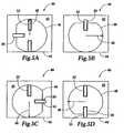
- FIG. 5Aa top view of such an apparatus 40 for lancing skin and positioning a disposable sensor to collect a liquid sample.
- the apparatus 40has a housing 42 with an outer periphery 44.
- the apparatus 40comprises a rotatable arm 46 (or disc 46) having a lance 48 and a nest 50 for receiving a disposable sensor.
- the housing 42contains cartridge 52 comprising a stack of disposable sensors.
- the disc 46is adapted to rotate three hundred and sixty degrees within the housing 42.
- the cartridge 52is sealed against the disc 46 and the lance 48 is stored.
- arm 46is rotated ninety degrees clockwise from the position shown in FIG. 5A .
- the nest 50is located under the cartridge 52 so that a new sensor can be loaded.
- the sensoris pushed into the nest 50 by spring pressure from within the cartridge 52.
- the lance 48is still located within the housing 42 and the lance drive, e.g., a spring, is cocked.
- the disc 46is rotated ninety degrees clockwise from the position shown in FIG. 5B .
- the lance 48is extended beyond the outer periphery 44 of the housing 42 to puncture the skin.
- a sensor 53 ejected from cartridge 52is shown on nest 50.
- the cartridge 52comprising the stack of disposable sensors has not been moved and is again sealed against the disc 46.
- the movable disc 46is rotated ninety degrees clockwise from the position shown in FIG. 5C .
- the lance 48is stored within the housing 42.
- the sensor 53 positioned on nest 50is positioned so that it is in substantially the same location as the lance site created by the lance 48. In this position of the disc 46, sensor 53 collects the liquid sample.
- the disc 46is rotated ninety more degrees clockwise to eject the now used sensor 53 and store the nest 50. The disc 46 is then in the position shown in FIG. 5A .
Landscapes
- Health & Medical Sciences (AREA)
- Life Sciences & Earth Sciences (AREA)
- Physics & Mathematics (AREA)
- Engineering & Computer Science (AREA)
- Molecular Biology (AREA)
- General Health & Medical Sciences (AREA)
- Biophysics (AREA)
- Biomedical Technology (AREA)
- Heart & Thoracic Surgery (AREA)
- Medical Informatics (AREA)
- Veterinary Medicine (AREA)
- Surgery (AREA)
- Animal Behavior & Ethology (AREA)
- Pathology (AREA)
- Public Health (AREA)
- Hematology (AREA)
- Manufacturing & Machinery (AREA)
- Geometry (AREA)
- Emergency Medicine (AREA)
- Optics & Photonics (AREA)
- Measurement Of The Respiration, Hearing Ability, Form, And Blood Characteristics Of Living Organisms (AREA)
Description
- The present invention relates generally to body fluid monitoring devices, and more particularly to a lancing mechanism and body fluid collection system.
- It is often necessary to obtain a sample of a body fluid and perform an analysis of an analyte in that body fluid. Preferably, the obtaining of body fluid is as painless as possible, and the collection of the sample is as simple as possible. One example of a need to obtain a sample of a body fluid is in connection with a blood glucose monitoring system where a user must frequently use the system to monitor the user's blood glucose level.
- Those who have irregular blood glucose concentration levels are medically required to regularly self-monitor their blood glucose concentration level. An irregular blood glucose level can be brought on by a variety of reasons including illness such as diabetes. The purpose of monitoring the blood glucose concentration level is to determine the blood glucose concentration level and then to take corrective action, based upon whether the level is too high or too low, to bring the level back within a normal range. The failure to take corrective action can have serious implications. When blood glucose levels drop too low - a condition known as hypoglycemia - a person can become nervous, shaky, and confused. That person's judgment may become impaired and that person may eventually pass out. A person can also become very ill if his blood glucose level becomes too high - a condition known as hyperglycemia. Both conditions, hypoglycemia and hyperglycemia, are both potentially life-threatening emergencies.
- One method of monitoring a person's blood glucose level is with a portable, hand-held blood glucose testing device. The portable nature of these devices enables the users to conveniently test their blood glucose levels wherever they may be. To check the blood glucose level, a drop of blood is obtained from the fingertip using a separate lancing device. The lancing device contains a needle lance to puncture the skin. Once the requisite amount of blood is produced on the fingertip, the blood is harvested using the blood glucose testing device. The blood is drawn inside the testing device, which then determines the concentration of glucose in the blood. The results of the test are communicated to the user via a display on the testing device.
- One problem related with the prior art devices containing a separate lance and sample collection mechanism i s that t he u ser m ust c arry b oth d evices w ith h im. T he need t o carry m ultiple d evices o pens the p ossibility o f forgetting o r 1 osing o ne o f the devices. If the user forgets to bring both the lance and the testing device with him, he will not be able to test his blood; adverse consequences may result.
- Another problem with a monitoring a system comprising a lancing device to lance the skin and a separate collection unit to collect the blood is that there is a greater chance of contaminating the sample. The user must be careful that he does not contaminate the blood drop that forms on the lance site or contaminate the collection device used. If any contamination occurs, the test result may not accurately reflect the level of the glucose present in the tested blood.
- A third problem with having a device for lancing and a separate device for collection is the size of the sample needed. Users prefer to make smaller cuts, also referred to as lance sites, on their skin to produce a blood sample. A smaller lance site is usually less painful to make than a larger lance site, and should heal more quickly than a larger lance site. Generally, a smaller lance site will produce a smaller blood sample. The smaller the sample, the more important proper collection of t he s ample becomes. And a smaller sample requires greater precision in placing the collection device relative to the lance site. If the collection device is not properly positioned relative to the lance site on the user's skin, the requisite amount of sample may not be collected. If the requisite amount of sample is not collected an underfill condition occurs. The results of analyzing an underfill will not accurately reflect the amount of glucose present in the sample, or in the user.
- Another problem with current lancing devices is that accidental lancing may occur from the exposed lance. If the lance is exposed it may come into contact with the user's skin in a location that the user did not intend to serve as a lance site. This cut may be painful and limit the available locations for a lance site.
- Accordingly, there exists the need of a device that combines lancing capability and collection capability into one instrument. The combination device should be suitable for lancing skin and aligning the collection device at the lance site, collecting a small sample of blood from a small lance site on the skin, and reducing risk of accidental lance sites being formed from an exposed lance.
- From the prior art the following devices are known:
US 5,314,441 discloses a lancet device for implementing an incision comprising a hollow housing means, a pivot arm supporting a blade located within said housing means, biasing means for biasing said pivot arm from a first position to a second position within said housing means, a guide within said housing means for guiding the path of said pivot arm from a first position to a second position, the guide causing a blade to emerge from the housing, create an incision with a slicing motion and return into the housing wherein the blade follows a generally tear drop shaped path between the first and the second position.WO 02/101359 A2 - An apparatus for lancing skin and collecting a liquid sample, having a housing with an outer periphery. The apparatus contains a rotatable arm having a lance to puncture the skin and a sample collection chamber attached to the arm. The arm of the apparatus rotates from a first position to a second position. As the arm rotates, the lance extends beyond the housing allowing the lance to contact the user's skin and create a lance site. As the arm continues to move to the second position, the lance is brought out of contact with the user's skin and back within the housing. When the arm is located in the second position, the collection area is in substantially the same location as the lance site on the user's skin.
- Other objects and advantages of the invention will become apparent upon reading the following detailed description in conjunction with the drawings in which:
FIG. 1 is a side view of an apparatus for sampling fluid and showing a housing and a rotatable arm.FIG. 2 is a side view of the apparatus shown inFIG. 1 with the arm in a first position with the lance in the housing.FIG. 3 is a side view of the apparatus shown inFIG. 2 as the arm rotates from the first position to a second position with the lance extended and lancing a site.FIG. 4 is a side view of the apparatus ofFIG. 3 with the arm in the second position with the lance in the housing and a collection area positioned at the lance site.FIG. 5A shows a top view of an alternate embodiment of the present invention in which a sample collection area can be removed from the apparatus.FIG. 5B illustrates the embodiment ofFIG. 5A as a new sample collection area is being loaded into the apparatus.FIG. 5C illustrates the embodiment ofFIG. 5A as the lance is extended beyond the outer periphery of the housing of the apparatus.FIG. 5D illustrates the embodiment ofFIG. 5A with the sample collection area positioned in substantially the same position as the lance site that was made as shown inFIG. 5C .- As discussed in the background section, the need to obtain a sample of blood and perform an analysis of that sample occurs frequently for persons with various medical conditions. Many people who suffer from conditions such as diabetes must regularly test the level of glucose contained in their blood. One way to perform this test would be with a device that combines the operation of lancing the skin and collecting the sample.
- Referring now to
FIG. 1 , anapparatus 10 for lancing skin and collecting a liquid sample is illustrated. Theapparatus 10 has ahousing 8 with anouter periphery 23. Amovable arm 11 is connected in thehousing 8 to swing in a predefined path. Connected tomovable arm 11 is alance 12 and asample collection area 13. As thearm 11 swings, thelance 12 is sequentially extended beyond theouter periphery 23 and retracted intohousing 8. - Referring now to
FIG. 2 , thearm 11, which comprises thelance 12, and thecollection area 13, pivots aboutpoint 22 as thearm 11. swings from a first position to a second position. Thelance 12 has asharp penetration end 14 that is capable of lancing a user, thereby creating a lance site on the skin to obtain a liquid sample for analysis. In a preferred embodiment, thelance 12 is a flat surface lying in the plane of rotation of thearm 11. The flat surface is useful to stabilize thelance 12 relatively to thearm 11. Thecollection area 13 is used to collect a liquid sample that forms at the lance site created by thelance 12. The second position of thearm 11 is predetermined to position thecollection area 13 at the lance site created as thearm 11 rotates tot he second rotation. - In one embodiment of the current invention, the
collection area 13 includes acapillary channel 15 through which the sample moves as it is collected. As the sample moves up thecapillary channel 15, displaced air exits from thecapillary channel 15 via avent hole 17. In the illustrated embodiment, thecollection area 13 includes abiosensor 16. - When an electrochemical biosensor is used, the
biosensor 16 contains a reagent designed to react with the analyte in the sample and produce a change in current. The change in current is measured across traces 18 and 19. Additional detail concerning electrochemical biosensors is found in commonly ownedU.S. Patent No. 5,759,364 . The change in current is measured by a meter coupled toterminals traces - The
collection area 13 may be provided with thebiosensor 16 having a reaction area that includes a reagent for producing a reaction with an analyte within the liquid sample 25. The reaction is indicative of the concentration of the analyte within that sample. In the case of a glucose tester, the reagent could be a mixture containing glucose oxidase and potassium ferricyanide. In one embodiment of the current invention, the biosensor is an electrochemical sensor. An optical sensor may also be used to analyze the liquid sample. - Another suitable biosensor is a colorimetric sensor; details of which is described in
U.S. Patent No. 5,723,284 . - To obtain a sample of blood, the user places the
apparatus 10 on hisskin 24 at a site t o 1 ance. I nFIG. 2 , the apparatus 1 0 i s applied t o theskin 24 of the user. Therotatable arm 11 is shown in a first position. Next, the user activates the device by for example, pressing the trigger mechanism on the apparatus 10 (not shown). Pressing the trigger releases a torsion spring (not shown) that forces thearm 11 to rotate from the first position to a second position. Thearm 11 is, in the illustrated embodiment, a pendulum that swings through a predefined arc aboutpivot point 22. - Referring now to
FIG. 3 , thearm 11 is between the first position and the second position. Thepenetration end 14 of thelance 12 extends beyond theouter periphery 23 of thehousing 8 to cut theskin 24 to a predetermined depth and create a lance site. The lance site on theskin 24 allows a liquid sample 25 (seeFIG. 4 ) to form near the lance site. - Referring now to
FIG. 4 , thearm 11 rotated to the second position. The second position is a predefined stopping point for thependulum 11 that positions thecollection area 13 over the lance site to collect the sample 25. At the second position, thepenetration end 14 oflance 12 is within thehousing 8. Thecollection area 13 is in substantially the same location of theskin 24 at which thepenetration end 14 of thelance 12 created the lance site. When thesample collection area 13 is over the lance site in theskin 24, the liquid sample 25 is able to move into thesample collection area 13 viacapillary channel 15, or be contacted by other sample structure used instead of the collection area.Figures 1-4 illustrate thecollection area 13 spaced apart from thelance 12. In some embodiments, thelance penetration end 14 andcollection area 13 are colocated. - A rotating lance, such as for example illustrated in
FIGS. 1-4 , can be combined with structure for storing a plurality of disposable sensors, in for example a cartridge. Referring now toFIG. 5A a top view of such anapparatus 40 for lancing skin and positioning a disposable sensor to collect a liquid sample. Theapparatus 40 has ahousing 42 with anouter periphery 44. Theapparatus 40 comprises a rotatable arm 46 (or disc 46) having alance 48 and anest 50 for receiving a disposable sensor. Thehousing 42 containscartridge 52 comprising a stack of disposable sensors. Thedisc 46 is adapted to rotate three hundred and sixty degrees within thehousing 42. InFIG. 5A , thecartridge 52 is sealed against thedisc 46 and thelance 48 is stored. - Referring now to
FIG. 5B ,arm 46 is rotated ninety degrees clockwise from the position shown inFIG. 5A . Thenest 50 is located under thecartridge 52 so that a new sensor can be loaded. The sensor is pushed into thenest 50 by spring pressure from within thecartridge 52. Thelance 48 is still located within thehousing 42 and the lance drive, e.g., a spring, is cocked. - Referring now to
FIG. 5C , thedisc 46 is rotated ninety degrees clockwise from the position shown inFIG. 5B . Thelance 48 is extended beyond theouter periphery 44 of thehousing 42 to puncture the skin. Asensor 53 ejected fromcartridge 52 is shown onnest 50. Thecartridge 52 comprising the stack of disposable sensors has not been moved and is again sealed against thedisc 46. - Referring now to
FIG. 5D , themovable disc 46 is rotated ninety degrees clockwise from the position shown inFIG. 5C . Thelance 48 is stored within thehousing 42. Thesensor 53 positioned onnest 50 is positioned so that it is in substantially the same location as the lance site created by thelance 48. In this position of thedisc 46,sensor 53 collects the liquid sample. - The
disc 46 is rotated ninety more degrees clockwise to eject the now usedsensor 53 and store thenest 50. Thedisc 46 is then in the position shown inFIG. 5A . - Further details concerning disposable sensors and device for dispensing sensors is found in
U.S. Patent Nos. D456,514 ;6,316,264 ;5,854,074 ;5,810,199 ; and5,632,410 . - While the invention is susceptible to various modifications and alternative forms, specific embodiments thereof have been shown by way of example in the drawings herein described in detail. It should be understood, however, that it is not intended to limit the invention to the particular forms disclosed, but on the contrary, the intention is to cover all modifications, equivalents, and alternatives falling within the scope of the invention as defined by the appended claims.
Claims (14)
- An apparatus (10) for lancing skin and collecting a liquid sample (25) comprising:a housing (8) sized to be handheld and having an outer periphery (23);a rotatable arm (11) rotatably positioned in the housing (8) and having an end movable from a first predefined position to a second predefined position;a lance (12) for lancing skin (24), the lance (12) being movable with the end of the rotatable arm (11), the lance (12) being fully within the outer periphery (23) of the housing (8) when the end of the rotatable arm (11) is in the first predefined position and the lance (12) extends beyond the outer periphery (23) of the housing (8) as the arm (11) is rotating from the first predefined position to the second predefined position to create a lance site in skin (24) of a user;characterized in
a sample collection area (13) movable with the end of the arm (11) in general fixed relation to the lance (12) as the arm (11) moves from the first predefined position to the second predefined position, the sample collection area (13) being positioned within an effective range of the lance site to collect the liquid sample (25) from the lance site when the arm (11) is at the second predefined position. - The apparatus (10) of Claim 1, wherein the sample collection area (13) overlaps at least a portion of the lance site when the arm is at the second predefined position.
- The apparatus (10) of Claim 1 or 2, wherein the end of the arm (11) moves in an arc from the first predefined position to the second predefined position.
- The apparatus (10) of Claim 3, wherein the end of the arm (11) moves in a continuous motion from the first predefined position to the second predefined position after being released.
- The apparatus (10) of one of the Claims 1 to 4, wherein the sample collection area (13) comprises a biosensor (16).
- The apparatus (10) of Claim 5, wherein the biosensor (16) is an electrochemical biosensor.
- The apparatus (10) of Claim 5, wherein the biosensor (16) is an optical biosensor.
- The apparatus (10) of one of the Claims 1 to 7, wherein the sample collection area (13) includes a capillary channel (15) for collecting the sample and moving the sample to a reaction area within the collection area (13), the reaction area having a reagent for producing a reaction with an analyte in the sample indicative of the concentration of the analyte in the sample (25).
- The apparatus (10) of one of the Claims 1 to 8, wherein the lance (12) comprises a generally flat blade end (14).
- The apparatus (10) of Claim 9, wherein the lance (12) lies along the arm (11) and the generally flat blade end (14) extends beyond the end of the arm (11).
- The apparatus (10) of one of the Claims 1 to 10, wherein the arm (11) comprises a nest at the end of the arm (11) in fixed relation to the lance (12) and a disposable sensor comprising the sample collection area is positioned in the nest.
- The apparatus (10) of one of the Claims 1 to 11, wherein the sample collection area (13) includes a mixture containing glucose oxidase and potassium ferricyanide.
- The apparatus of one of the Claims 1 to 12, wherein the end of the rotatable arm (11) is adapted to move in a single direction from the first predefined position to the second predefined position in creating a lance site and positioning the sample collection area (13).
- The apparatus of one of the Claims 1 to 12, wherein the sample collection area (13) is distinct and separate from the lance (12).
Applications Claiming Priority (2)
| Application Number | Priority Date | Filing Date | Title |
|---|---|---|---|
| US49001903P | 2003-07-28 | 2003-07-28 | |
| US490019P | 2003-07-28 |
Publications (2)
| Publication Number | Publication Date |
|---|---|
| EP1502547A1 EP1502547A1 (en) | 2005-02-02 |
| EP1502547B1true EP1502547B1 (en) | 2009-12-23 |
Family
ID=33539365
Family Applications (1)
| Application Number | Title | Priority Date | Filing Date |
|---|---|---|---|
| EP04017290AExpired - LifetimeEP1502547B1 (en) | 2003-07-28 | 2004-07-22 | Swing lance with integrated sensor |
Country Status (6)
| Country | Link |
|---|---|
| US (2) | US7670300B2 (en) |
| EP (1) | EP1502547B1 (en) |
| JP (1) | JP4652738B2 (en) |
| AU (1) | AU2004203280A1 (en) |
| CA (1) | CA2475670A1 (en) |
| DE (1) | DE602004024749D1 (en) |
Families Citing this family (100)
| Publication number | Priority date | Publication date | Assignee | Title |
|---|---|---|---|---|
| US6036924A (en)* | 1997-12-04 | 2000-03-14 | Hewlett-Packard Company | Cassette of lancet cartridges for sampling blood |
| US6391005B1 (en) | 1998-03-30 | 2002-05-21 | Agilent Technologies, Inc. | Apparatus and method for penetration with shaft having a sensor for sensing penetration depth |
| DE10057832C1 (en) | 2000-11-21 | 2002-02-21 | Hartmann Paul Ag | Blood analysis device has syringe mounted in casing, annular mounting carrying needles mounted behind test strip and being swiveled so that needle can be pushed through strip and aperture in casing to take blood sample |
| US8641644B2 (en) | 2000-11-21 | 2014-02-04 | Sanofi-Aventis Deutschland Gmbh | Blood testing apparatus having a rotatable cartridge with multiple lancing elements and testing means |
| US7310543B2 (en)* | 2001-03-26 | 2007-12-18 | Kumetrix, Inc. | Silicon microprobe with integrated biosensor |
| US7041068B2 (en)* | 2001-06-12 | 2006-05-09 | Pelikan Technologies, Inc. | Sampling module device and method |
| WO2002101359A2 (en) | 2001-06-12 | 2002-12-19 | Pelikan Technologies, Inc. | Integrated blood sampling analysis system with multi-use sampling module |
| US9427532B2 (en) | 2001-06-12 | 2016-08-30 | Sanofi-Aventis Deutschland Gmbh | Tissue penetration device |
| US9226699B2 (en) | 2002-04-19 | 2016-01-05 | Sanofi-Aventis Deutschland Gmbh | Body fluid sampling module with a continuous compression tissue interface surface |
| US7344507B2 (en) | 2002-04-19 | 2008-03-18 | Pelikan Technologies, Inc. | Method and apparatus for lancet actuation |
| JP4272051B2 (en)* | 2001-06-12 | 2009-06-03 | ペリカン テクノロジーズ インコーポレイテッド | Blood sampling apparatus and method |
| US7749174B2 (en) | 2001-06-12 | 2010-07-06 | Pelikan Technologies, Inc. | Method and apparatus for lancet launching device intergrated onto a blood-sampling cartridge |
| US8337419B2 (en) | 2002-04-19 | 2012-12-25 | Sanofi-Aventis Deutschland Gmbh | Tissue penetration device |
| US7981056B2 (en) | 2002-04-19 | 2011-07-19 | Pelikan Technologies, Inc. | Methods and apparatus for lancet actuation |
| US9795747B2 (en) | 2010-06-02 | 2017-10-24 | Sanofi-Aventis Deutschland Gmbh | Methods and apparatus for lancet actuation |
| AU2002344825A1 (en)* | 2001-06-12 | 2002-12-23 | Pelikan Technologies, Inc. | Method and apparatus for improving success rate of blood yield from a fingerstick |
| EP1395185B1 (en) | 2001-06-12 | 2010-10-27 | Pelikan Technologies Inc. | Electric lancet actuator |
| JP4209767B2 (en) | 2001-06-12 | 2009-01-14 | ペリカン テクノロジーズ インコーポレイテッド | Self-optimized cutting instrument with adaptive means for temporary changes in skin properties |
| DE10134650B4 (en) | 2001-07-20 | 2009-12-03 | Roche Diagnostics Gmbh | System for taking small amounts of body fluid |
| US7344894B2 (en) | 2001-10-16 | 2008-03-18 | Agilent Technologies, Inc. | Thermal regulation of fluidic samples within a diagnostic cartridge |
| US7004928B2 (en) | 2002-02-08 | 2006-02-28 | Rosedale Medical, Inc. | Autonomous, ambulatory analyte monitor or drug delivery device |
| US7563232B2 (en)* | 2002-04-19 | 2009-07-21 | Pelikan Technologies, Inc. | Method and apparatus for penetrating tissue |
| US7976476B2 (en)* | 2002-04-19 | 2011-07-12 | Pelikan Technologies, Inc. | Device and method for variable speed lancet |
| US9795334B2 (en) | 2002-04-19 | 2017-10-24 | Sanofi-Aventis Deutschland Gmbh | Method and apparatus for penetrating tissue |
| US7524293B2 (en) | 2002-04-19 | 2009-04-28 | Pelikan Technologies, Inc. | Method and apparatus for penetrating tissue |
| US7229458B2 (en) | 2002-04-19 | 2007-06-12 | Pelikan Technologies, Inc. | Method and apparatus for penetrating tissue |
| US7371247B2 (en)* | 2002-04-19 | 2008-05-13 | Pelikan Technologies, Inc | Method and apparatus for penetrating tissue |
| US8221334B2 (en) | 2002-04-19 | 2012-07-17 | Sanofi-Aventis Deutschland Gmbh | Method and apparatus for penetrating tissue |
| US7582099B2 (en) | 2002-04-19 | 2009-09-01 | Pelikan Technologies, Inc | Method and apparatus for penetrating tissue |
| US7717863B2 (en) | 2002-04-19 | 2010-05-18 | Pelikan Technologies, Inc. | Method and apparatus for penetrating tissue |
| US8267870B2 (en) | 2002-04-19 | 2012-09-18 | Sanofi-Aventis Deutschland Gmbh | Method and apparatus for body fluid sampling with hybrid actuation |
| US7141058B2 (en)* | 2002-04-19 | 2006-11-28 | Pelikan Technologies, Inc. | Method and apparatus for a body fluid sampling device using illumination |
| US9248267B2 (en) | 2002-04-19 | 2016-02-02 | Sanofi-Aventis Deustchland Gmbh | Tissue penetration device |
| US7674232B2 (en) | 2002-04-19 | 2010-03-09 | Pelikan Technologies, Inc. | Method and apparatus for penetrating tissue |
| US7892183B2 (en) | 2002-04-19 | 2011-02-22 | Pelikan Technologies, Inc. | Method and apparatus for body fluid sampling and analyte sensing |
| US7374544B2 (en) | 2002-04-19 | 2008-05-20 | Pelikan Technologies, Inc. | Method and apparatus for penetrating tissue |
| US7901362B2 (en) | 2002-04-19 | 2011-03-08 | Pelikan Technologies, Inc. | Method and apparatus for penetrating tissue |
| US7547287B2 (en) | 2002-04-19 | 2009-06-16 | Pelikan Technologies, Inc. | Method and apparatus for penetrating tissue |
| US7297122B2 (en) | 2002-04-19 | 2007-11-20 | Pelikan Technologies, Inc. | Method and apparatus for penetrating tissue |
| US9314194B2 (en) | 2002-04-19 | 2016-04-19 | Sanofi-Aventis Deutschland Gmbh | Tissue penetration device |
| US8579831B2 (en) | 2002-04-19 | 2013-11-12 | Sanofi-Aventis Deutschland Gmbh | Method and apparatus for penetrating tissue |
| US7491178B2 (en) | 2002-04-19 | 2009-02-17 | Pelikan Technologies, Inc. | Method and apparatus for penetrating tissue |
| US7410468B2 (en) | 2002-04-19 | 2008-08-12 | Pelikan Technologies, Inc. | Method and apparatus for penetrating tissue |
| US8784335B2 (en) | 2002-04-19 | 2014-07-22 | Sanofi-Aventis Deutschland Gmbh | Body fluid sampling device with a capacitive sensor |
| US7481776B2 (en)* | 2002-04-19 | 2009-01-27 | Pelikan Technologies, Inc. | Method and apparatus for penetrating tissue |
| US7708701B2 (en) | 2002-04-19 | 2010-05-04 | Pelikan Technologies, Inc. | Method and apparatus for a multi-use body fluid sampling device |
| US7909778B2 (en) | 2002-04-19 | 2011-03-22 | Pelikan Technologies, Inc. | Method and apparatus for penetrating tissue |
| US8702624B2 (en) | 2006-09-29 | 2014-04-22 | Sanofi-Aventis Deutschland Gmbh | Analyte measurement device with a single shot actuator |
| US7291117B2 (en) | 2002-04-19 | 2007-11-06 | Pelikan Technologies, Inc. | Method and apparatus for penetrating tissue |
| US7331931B2 (en) | 2002-04-19 | 2008-02-19 | Pelikan Technologies, Inc. | Method and apparatus for penetrating tissue |
| US7232451B2 (en) | 2002-04-19 | 2007-06-19 | Pelikan Technologies, Inc. | Method and apparatus for penetrating tissue |
| US7648468B2 (en) | 2002-04-19 | 2010-01-19 | Pelikon Technologies, Inc. | Method and apparatus for penetrating tissue |
| US7815579B2 (en) | 2005-03-02 | 2010-10-19 | Roche Diagnostics Operations, Inc. | Dynamic integrated lancing test strip with sterility cover |
| US7214200B2 (en)* | 2002-12-30 | 2007-05-08 | Roche Diagnostics Operations, Inc. | Integrated analytical test element |
| US8574895B2 (en) | 2002-12-30 | 2013-11-05 | Sanofi-Aventis Deutschland Gmbh | Method and apparatus using optical techniques to measure analyte levels |
| WO2004060174A2 (en)* | 2002-12-31 | 2004-07-22 | Pelikan Technologies Inc. | Method and apparatus for loading penetrating members |
| US7850621B2 (en) | 2003-06-06 | 2010-12-14 | Pelikan Technologies, Inc. | Method and apparatus for body fluid sampling and analyte sensing |
| WO2006001797A1 (en) | 2004-06-14 | 2006-01-05 | Pelikan Technologies, Inc. | Low pain penetrating |
| EP1635700B1 (en) | 2003-06-13 | 2016-03-09 | Sanofi-Aventis Deutschland GmbH | Apparatus for a point of care device |
| US8282576B2 (en) | 2003-09-29 | 2012-10-09 | Sanofi-Aventis Deutschland Gmbh | Method and apparatus for an improved sample capture device |
| EP1680014A4 (en) | 2003-10-14 | 2009-01-21 | Pelikan Technologies Inc | METHOD AND DEVICE FOR A VARIABLE USER INTERFACE |
| US8668656B2 (en) | 2003-12-31 | 2014-03-11 | Sanofi-Aventis Deutschland Gmbh | Method and apparatus for improving fluidic flow and sample capture |
| US7822454B1 (en) | 2005-01-03 | 2010-10-26 | Pelikan Technologies, Inc. | Fluid sampling device with improved analyte detecting member configuration |
| WO2005089333A2 (en)* | 2004-03-15 | 2005-09-29 | Oakville Hong Kong Company Limited | Lancet device and method of use |
| WO2006011062A2 (en) | 2004-05-20 | 2006-02-02 | Albatros Technologies Gmbh & Co. Kg | Printable hydrogel for biosensors |
| WO2005120365A1 (en) | 2004-06-03 | 2005-12-22 | Pelikan Technologies, Inc. | Method and apparatus for a fluid sampling device |
| US20070255300A1 (en)* | 2004-08-19 | 2007-11-01 | Facet Technologies, Llc | Loosely coupled lancet |
| US8652831B2 (en) | 2004-12-30 | 2014-02-18 | Sanofi-Aventis Deutschland Gmbh | Method and apparatus for analyte measurement test time |
| US7935063B2 (en)* | 2005-03-02 | 2011-05-03 | Roche Diagnostics Operations, Inc. | System and method for breaking a sterility seal to engage a lancet |
| US7695442B2 (en) | 2005-04-12 | 2010-04-13 | Roche Diagnostics Operations, Inc. | Integrated lancing test strip with retractable lancet |
| EP1698279A1 (en) | 2005-03-04 | 2006-09-06 | Disetronic Licensing AG | Sequential insertion of main-penetrators |
| US8157749B2 (en)* | 2005-05-16 | 2012-04-17 | Terumo Kabushiki Kaisha | Blood component measurement device and tip for blood measurement |
| US20060281187A1 (en) | 2005-06-13 | 2006-12-14 | Rosedale Medical, Inc. | Analyte detection devices and methods with hematocrit/volume correction and feedback control |
| EP1928302B1 (en) | 2005-09-30 | 2012-08-01 | Intuity Medical, Inc. | Fully integrated wearable or handheld monitor |
| US8801631B2 (en) | 2005-09-30 | 2014-08-12 | Intuity Medical, Inc. | Devices and methods for facilitating fluid transport |
| US8105244B2 (en)* | 2005-11-30 | 2012-01-31 | Abbott Diabetes Care Inc. | Integrated sensor for analyzing biological samples |
| EP1878386A1 (en)* | 2006-07-15 | 2008-01-16 | Roche Diagnostics GmbH | Process to produce lancet; lancet, lancet band and device for pricking the skin |
| EP1878387B1 (en)* | 2006-07-15 | 2010-11-24 | Roche Diagnostics GmbH | Lancet, lancet feeder belt and pricking device for creating a puncture wound |
| US7846110B2 (en)* | 2006-08-03 | 2010-12-07 | Advanced Medical Products Gmbh | Self-contained test unit for testing body fluids |
| CA2671441C (en)* | 2006-12-01 | 2015-10-20 | Medipurpose Pte Ltd | A device for performing an incision |
| EP2265324B1 (en) | 2008-04-11 | 2015-01-28 | Sanofi-Aventis Deutschland GmbH | Integrated analyte measurement system |
| US9833183B2 (en) | 2008-05-30 | 2017-12-05 | Intuity Medical, Inc. | Body fluid sampling device—sampling site interface |
| EP3984454A1 (en) | 2008-06-06 | 2022-04-20 | Intuity Medical, Inc. | Medical diagnostic devices and methods |
| WO2009148624A1 (en) | 2008-06-06 | 2009-12-10 | Intuity Medical, Inc. | Detection meter and mode of operation |
| US9375169B2 (en) | 2009-01-30 | 2016-06-28 | Sanofi-Aventis Deutschland Gmbh | Cam drive for managing disposable penetrating member actions with a single motor and motor and control system |
| EP2506768B1 (en) | 2009-11-30 | 2016-07-06 | Intuity Medical, Inc. | Calibration material delivery devices and methods |
| US8965476B2 (en) | 2010-04-16 | 2015-02-24 | Sanofi-Aventis Deutschland Gmbh | Tissue penetration device |
| CA2803797A1 (en) | 2010-06-25 | 2011-12-29 | Intuity Medical, Inc. | Analyte monitoring methods and systems |
| TW201212887A (en)* | 2010-07-08 | 2012-04-01 | Sanofi Aventis Deutschland | Eliciting a blood sample |
| US9782114B2 (en) | 2011-08-03 | 2017-10-10 | Intuity Medical, Inc. | Devices and methods for body fluid sampling and analysis |
| EP2802269B1 (en)* | 2012-01-10 | 2015-12-09 | Sanofi-Aventis Deutschland GmbH | An apparatus for eliciting a blood sample |
| US20130211289A1 (en) | 2012-01-25 | 2013-08-15 | Tasso, Inc. | Handheld Device for Drawing, Collecting, and Analyzing Bodily Fluid |
| WO2014205412A1 (en) | 2013-06-21 | 2014-12-24 | Intuity Medical, Inc. | Analyte monitoring system with audible feedback |
| USD742004S1 (en) | 2014-02-18 | 2015-10-27 | “HTL-STREFA” Spólka Akcyjna | Skin incision device |
| CN106999120B (en) | 2014-08-01 | 2021-05-14 | 塔索公司 | Devices, systems, and methods for gravity-enhanced microfluidic collection, handling, and delivery of liquids |
| CA3009328C (en) | 2015-12-21 | 2024-03-05 | Tasso, Inc. | Devices, systems and methods for actuation and retraction in fluid collection |
| JP7460607B2 (en) | 2018-09-14 | 2024-04-02 | タッソ インコーポレイテッド | Body fluid collection devices and related methods |
| CN210204740U (en)* | 2019-03-22 | 2020-03-31 | 北京京东方光电科技有限公司 | A blood sugar detection device |
| AU2022227019A1 (en) | 2021-02-26 | 2023-08-31 | Tasso, Inc. | Bodily fluid collection devices and related methods |
| US12185972B2 (en)* | 2021-11-05 | 2025-01-07 | Nuvasive, Inc. | Cutting apparatus |
Family Cites Families (28)
| Publication number | Priority date | Publication date | Assignee | Title |
|---|---|---|---|---|
| SE369144B (en)* | 1972-08-21 | 1974-08-12 | N Jacobson | |
| IT1044642B (en)* | 1975-10-13 | 1980-04-21 | Farmaceutici Italia | IMPROVED APPARATUS FOR MAKING PERFORMANCE CUTANEOUS CUTS |
| US4643189A (en) | 1985-02-19 | 1987-02-17 | W. T. Associates | Apparatus for implementing a standardized skin incision |
| US4627445A (en) | 1985-04-08 | 1986-12-09 | Garid, Inc. | Glucose medical monitoring system |
| US4924879A (en)* | 1988-10-07 | 1990-05-15 | Brien Walter J O | Blood lancet device |
| US5035704A (en)* | 1989-03-07 | 1991-07-30 | Lambert Robert D | Blood sampling mechanism |
| US5231993A (en) | 1991-11-20 | 1993-08-03 | Habley Medical Technology Corporation | Blood sampler and component tester with guide member |
| US5314441A (en) | 1992-10-16 | 1994-05-24 | International Technidyne Corporation | Disposable slicing lancet assembly |
| US5630986A (en)* | 1995-01-13 | 1997-05-20 | Bayer Corporation | Dispensing instrument for fluid monitoring sensors |
| CA2170560C (en)* | 1995-04-17 | 2005-10-25 | Joseph L. Moulton | Means of handling multiple sensors in a glucose monitoring instrument system |
| WO1997010745A1 (en)* | 1995-09-08 | 1997-03-27 | Integ, Inc. | Body fluid sampler |
| US5723284A (en)* | 1996-04-01 | 1998-03-03 | Bayer Corporation | Control solution and method for testing the performance of an electrochemical device for determining the concentration of an analyte in blood |
| US5879311A (en)* | 1996-05-17 | 1999-03-09 | Mercury Diagnostics, Inc. | Body fluid sampling device and methods of use |
| US5810199A (en)* | 1996-06-10 | 1998-09-22 | Bayer Corporation | Dispensing instrument for fluid monitoring sensor |
| US5772677A (en) | 1996-09-24 | 1998-06-30 | International Technidyne Corporation | Incision device capable of automatic assembly and a method of assembly |
| US5759364A (en)* | 1997-05-02 | 1998-06-02 | Bayer Corporation | Electrochemical biosensor |
| US5948695A (en) | 1997-06-17 | 1999-09-07 | Mercury Diagnostics, Inc. | Device for determination of an analyte in a body fluid |
| US5971941A (en)* | 1997-12-04 | 1999-10-26 | Hewlett-Packard Company | Integrated system and method for sampling blood and analysis |
| JP4210782B2 (en)* | 1999-10-13 | 2009-01-21 | アークレイ株式会社 | Blood sampling position indicator |
| US6316264B1 (en)* | 1999-12-17 | 2001-11-13 | Bayer Corporation | Test strip for the assay of an analyte in a liquid sample |
| US6706159B2 (en)* | 2000-03-02 | 2004-03-16 | Diabetes Diagnostics | Combined lancet and electrochemical analyte-testing apparatus |
| DE10057832C1 (en)* | 2000-11-21 | 2002-02-21 | Hartmann Paul Ag | Blood analysis device has syringe mounted in casing, annular mounting carrying needles mounted behind test strip and being swiveled so that needle can be pushed through strip and aperture in casing to take blood sample |
| EP1328192B1 (en)* | 2001-03-29 | 2011-01-05 | Lifescan Scotland Ltd | Integrated sample testing meter |
| US6783502B2 (en)* | 2001-04-26 | 2004-08-31 | Phoenix Bioscience | Integrated lancing and analytic device |
| US6988996B2 (en)* | 2001-06-08 | 2006-01-24 | Roche Diagnostics Operatons, Inc. | Test media cassette for bodily fluid testing device |
| WO2002101359A2 (en) | 2001-06-12 | 2002-12-19 | Pelikan Technologies, Inc. | Integrated blood sampling analysis system with multi-use sampling module |
| USD456514S1 (en) | 2001-09-14 | 2002-04-30 | Bayer Corporation | Blood glucose sensor dispensing instrument |
| US20040225312A1 (en)* | 2003-05-09 | 2004-11-11 | Phoenix Bioscience | Linearly lancing integrated pivot disposable |
- 2004
- 2004-07-20AUAU2004203280Apatent/AU2004203280A1/ennot_activeAbandoned
- 2004-07-21CACA002475670Apatent/CA2475670A1/ennot_activeAbandoned
- 2004-07-22DEDE602004024749Tpatent/DE602004024749D1/ennot_activeExpired - Lifetime
- 2004-07-22EPEP04017290Apatent/EP1502547B1/ennot_activeExpired - Lifetime
- 2004-07-27JPJP2004218220Apatent/JP4652738B2/ennot_activeExpired - Fee Related
- 2004-07-27USUS10/899,774patent/US7670300B2/ennot_activeExpired - Fee Related
- 2010
- 2010-01-13USUS12/686,942patent/US8251920B2/ennot_activeExpired - Lifetime
Also Published As
| Publication number | Publication date |
|---|---|
| US20100152617A1 (en) | 2010-06-17 |
| JP4652738B2 (en) | 2011-03-16 |
| JP2005046628A (en) | 2005-02-24 |
| DE602004024749D1 (en) | 2010-02-04 |
| AU2004203280A1 (en) | 2005-02-17 |
| US20050033341A1 (en) | 2005-02-10 |
| US7670300B2 (en) | 2010-03-02 |
| US8251920B2 (en) | 2012-08-28 |
| EP1502547A1 (en) | 2005-02-02 |
| CA2475670A1 (en) | 2005-01-28 |
Similar Documents
| Publication | Publication Date | Title |
|---|---|---|
| EP1502547B1 (en) | Swing lance with integrated sensor | |
| EP1328192B1 (en) | Integrated sample testing meter | |
| EP1174083B1 (en) | Thin lancet for test sensor | |
| US7343188B2 (en) | Devices and methods for accessing and analyzing physiological fluid | |
| EP2080476B1 (en) | Sensor with integrated lancet | |
| JP4468324B2 (en) | Analysis aid | |
| US8419657B2 (en) | Device for sampling bodily fluids | |
| EP1369083B1 (en) | Test strip container system | |
| US20040225312A1 (en) | Linearly lancing integrated pivot disposable | |
| US20110257559A1 (en) | System for withdrawing small amounts of body fluid | |
| JP2005521452A (en) | Integrated sample tester | |
| US20080119760A1 (en) | Marker For Readings Taken From Alternative Site Tests | |
| JP2022056636A (en) | Blood component measurement device | |
| AU2002244851A1 (en) | Integrated sample testing meter |
Legal Events
| Date | Code | Title | Description |
|---|---|---|---|
| PUAI | Public reference made under article 153(3) epc to a published international application that has entered the european phase | Free format text:ORIGINAL CODE: 0009012 | |
| AK | Designated contracting states | Kind code of ref document:A1 Designated state(s):AT BE BG CH CY CZ DE DK EE ES FI FR GB GR HU IE IT LI LU MC NL PL PT RO SE SI SK TR | |
| AX | Request for extension of the european patent | Extension state:AL HR LT LV MK | |
| 17P | Request for examination filed | Effective date:20050802 | |
| AKX | Designation fees paid | Designated state(s):DE FR GB IT | |
| RAP1 | Party data changed (applicant data changed or rights of an application transferred) | Owner name:BAYER HEALTHCARE LLC | |
| 17Q | First examination report despatched | Effective date:20080408 | |
| GRAP | Despatch of communication of intention to grant a patent | Free format text:ORIGINAL CODE: EPIDOSNIGR1 | |
| GRAS | Grant fee paid | Free format text:ORIGINAL CODE: EPIDOSNIGR3 | |
| GRAA | (expected) grant | Free format text:ORIGINAL CODE: 0009210 | |
| RAP1 | Party data changed (applicant data changed or rights of an application transferred) | Owner name:BAYER HEALTHCARE LLC | |
| AK | Designated contracting states | Kind code of ref document:B1 Designated state(s):DE FR GB IT | |
| REG | Reference to a national code | Ref country code:GB Ref legal event code:FG4D | |
| REF | Corresponds to: | Ref document number:602004024749 Country of ref document:DE Date of ref document:20100204 Kind code of ref document:P | |
| PLBE | No opposition filed within time limit | Free format text:ORIGINAL CODE: 0009261 | |
| STAA | Information on the status of an ep patent application or granted ep patent | Free format text:STATUS: NO OPPOSITION FILED WITHIN TIME LIMIT | |
| 26N | No opposition filed | Effective date:20100924 | |
| PGFP | Annual fee paid to national office [announced via postgrant information from national office to epo] | Ref country code:FR Payment date:20110805 Year of fee payment:8 | |
| PGFP | Annual fee paid to national office [announced via postgrant information from national office to epo] | Ref country code:GB Payment date:20110725 Year of fee payment:8 | |
| PGFP | Annual fee paid to national office [announced via postgrant information from national office to epo] | Ref country code:IT Payment date:20110722 Year of fee payment:8 | |
| PGFP | Annual fee paid to national office [announced via postgrant information from national office to epo] | Ref country code:DE Payment date:20120727 Year of fee payment:9 | |
| GBPC | Gb: european patent ceased through non-payment of renewal fee | Effective date:20120722 | |
| REG | Reference to a national code | Ref country code:FR Ref legal event code:ST Effective date:20130329 | |
| PG25 | Lapsed in a contracting state [announced via postgrant information from national office to epo] | Ref country code:GB Free format text:LAPSE BECAUSE OF NON-PAYMENT OF DUE FEES Effective date:20120722 Ref country code:FR Free format text:LAPSE BECAUSE OF NON-PAYMENT OF DUE FEES Effective date:20120731 | |
| PG25 | Lapsed in a contracting state [announced via postgrant information from national office to epo] | Ref country code:IT Free format text:LAPSE BECAUSE OF NON-PAYMENT OF DUE FEES Effective date:20120722 | |
| PG25 | Lapsed in a contracting state [announced via postgrant information from national office to epo] | Ref country code:DE Free format text:LAPSE BECAUSE OF NON-PAYMENT OF DUE FEES Effective date:20140201 | |
| REG | Reference to a national code | Ref country code:DE Ref legal event code:R119 Ref document number:602004024749 Country of ref document:DE Effective date:20140201 |