EP1501427B1 - Sampling module - Google Patents
Sampling moduleDownload PDFInfo
- Publication number
- EP1501427B1 EP1501427B1EP02744400.9AEP02744400AEP1501427B1EP 1501427 B1EP1501427 B1EP 1501427B1EP 02744400 AEP02744400 AEP 02744400AEP 1501427 B1EP1501427 B1EP 1501427B1
- Authority
- EP
- European Patent Office
- Prior art keywords
- lancet
- sample
- sampling module
- driver
- sampling
- Prior art date
- Legal status (The legal status is an assumption and is not a legal conclusion. Google has not performed a legal analysis and makes no representation as to the accuracy of the status listed.)
- Expired - Lifetime
Links
- 238000005070samplingMethods0.000titleclaimsdescription374
- 239000012530fluidSubstances0.000claimsdescription101
- 230000033001locomotionEffects0.000claimsdescription45
- 238000004891communicationMethods0.000claimsdescription24
- 230000009471actionEffects0.000claimsdescription17
- 238000012790confirmationMethods0.000claimsdescription6
- 230000007704transitionEffects0.000claimsdescription4
- 239000000523sampleSubstances0.000description378
- 210000003491skinAnatomy0.000description187
- 210000004369bloodAnatomy0.000description172
- 239000008280bloodSubstances0.000description172
- 230000035515penetrationEffects0.000description114
- 210000001519tissueAnatomy0.000description105
- 238000000034methodMethods0.000description99
- 238000004458analytical methodMethods0.000description64
- 238000012360testing methodMethods0.000description60
- 239000000463materialSubstances0.000description47
- 206010052428WoundDiseases0.000description44
- 208000027418Wounds and injuryDiseases0.000description43
- 230000003287optical effectEffects0.000description41
- XEEYBQQBJWHFJM-UHFFFAOYSA-NIronChemical compound[Fe]XEEYBQQBJWHFJM-UHFFFAOYSA-N0.000description40
- 238000006073displacement reactionMethods0.000description35
- 239000012528membraneSubstances0.000description30
- 230000008569processEffects0.000description29
- 239000003795chemical substances by applicationSubstances0.000description28
- 239000003814drugSubstances0.000description28
- 229940079593drugDrugs0.000description28
- 229920005570flexible polymerPolymers0.000description24
- 238000010438heat treatmentMethods0.000description24
- 238000002347injectionMethods0.000description24
- 239000007924injectionSubstances0.000description24
- 230000007246mechanismEffects0.000description24
- 239000004020conductorSubstances0.000description23
- 238000005259measurementMethods0.000description23
- 238000005520cutting processMethods0.000description22
- 230000036316preloadEffects0.000description21
- 238000001514detection methodMethods0.000description20
- 229920000642polymerPolymers0.000description19
- 230000000153supplemental effectEffects0.000description19
- 230000008859changeEffects0.000description18
- 230000006870functionEffects0.000description18
- WQZGKKKJIJFFOK-GASJEMHNSA-NGlucoseNatural productsOC[C@H]1OC(O)[C@H](O)[C@@H](O)[C@@H]1OWQZGKKKJIJFFOK-GASJEMHNSA-N0.000description17
- 239000008103glucoseSubstances0.000description17
- 238000010241blood samplingMethods0.000description16
- 229910052742ironInorganic materials0.000description16
- 230000036407painEffects0.000description16
- 239000000758substrateSubstances0.000description16
- 230000001276controlling effectEffects0.000description15
- 238000010586diagramMethods0.000description15
- 230000001133accelerationEffects0.000description14
- -1ferrous metalsChemical class0.000description14
- 239000000853adhesiveSubstances0.000description13
- 230000001070adhesive effectEffects0.000description13
- 230000008878couplingEffects0.000description12
- 238000010168coupling processMethods0.000description12
- 238000005859coupling reactionMethods0.000description12
- 230000002829reductive effectEffects0.000description11
- 239000002131composite materialSubstances0.000description10
- 238000004519manufacturing processMethods0.000description10
- 229910052751metalInorganic materials0.000description10
- 239000002184metalSubstances0.000description10
- 239000000243solutionSubstances0.000description10
- 238000003860storageMethods0.000description10
- 239000000126substanceSubstances0.000description10
- 238000000576coating methodMethods0.000description9
- 230000000977initiatory effectEffects0.000description9
- 230000036961partial effectEffects0.000description9
- 230000002269spontaneous effectEffects0.000description9
- 239000011248coating agentSubstances0.000description8
- 230000001419dependent effectEffects0.000description8
- 238000012544monitoring processMethods0.000description8
- 229920001296polysiloxanePolymers0.000description8
- 238000004804windingMethods0.000description8
- 229910000831SteelInorganic materials0.000description7
- 238000003556assayMethods0.000description7
- 230000000875corresponding effectEffects0.000description7
- 229920001971elastomerPolymers0.000description7
- 238000011049fillingMethods0.000description7
- 230000000149penetrating effectEffects0.000description7
- 239000010959steelSubstances0.000description7
- 229920002799BoPETPolymers0.000description6
- RYGMFSIKBFXOCR-UHFFFAOYSA-NCopperChemical compound[Cu]RYGMFSIKBFXOCR-UHFFFAOYSA-N0.000description6
- 230000008901benefitEffects0.000description6
- 238000011109contaminationMethods0.000description6
- 230000007423decreaseEffects0.000description6
- 238000012377drug deliveryMethods0.000description6
- 239000000806elastomerSubstances0.000description6
- 230000005684electric fieldEffects0.000description6
- 230000036571hydrationEffects0.000description6
- 238000006703hydration reactionMethods0.000description6
- 238000003780insertionMethods0.000description6
- 230000037431insertionEffects0.000description6
- 238000012546transferMethods0.000description6
- 239000004642PolyimideSubstances0.000description5
- 239000003570airSubstances0.000description5
- 238000012863analytical testingMethods0.000description5
- 230000017531blood circulationEffects0.000description5
- 210000001124body fluidAnatomy0.000description5
- 230000000295complement effectEffects0.000description5
- 230000003750conditioning effectEffects0.000description5
- 230000001976improved effectEffects0.000description5
- 239000000696magnetic materialSubstances0.000description5
- 229920003229poly(methyl methacrylate)Polymers0.000description5
- 229920001721polyimidePolymers0.000description5
- 239000004926polymethyl methacrylateSubstances0.000description5
- 230000004044responseEffects0.000description5
- 210000000434stratum corneumAnatomy0.000description5
- 238000013519translationMethods0.000description5
- 229960005486vaccineDrugs0.000description5
- 229910000859α-FeInorganic materials0.000description5
- 210000004204blood vesselAnatomy0.000description4
- 239000010839body fluidSubstances0.000description4
- 238000006243chemical reactionMethods0.000description4
- 239000003153chemical reaction reagentSubstances0.000description4
- 210000004207dermisAnatomy0.000description4
- 238000013461designMethods0.000description4
- 206010012601diabetes mellitusDiseases0.000description4
- 230000004907fluxEffects0.000description4
- 230000002209hydrophobic effectEffects0.000description4
- 230000006698inductionEffects0.000description4
- 238000011068loading methodMethods0.000description4
- 229920003023plasticPolymers0.000description4
- 239000004033plasticSubstances0.000description4
- 238000003825pressingMethods0.000description4
- 238000007789sealingMethods0.000description4
- 230000035945sensitivityEffects0.000description4
- 239000010935stainless steelSubstances0.000description4
- 229910001220stainless steelInorganic materials0.000description4
- 230000003797telogen phaseEffects0.000description4
- GYTROFMCUJZKNA-UHFFFAOYSA-Ntriethyl triethoxysilyl silicateChemical compoundCCO[Si](OCC)(OCC)O[Si](OCC)(OCC)OCCGYTROFMCUJZKNA-UHFFFAOYSA-N0.000description4
- 238000007514turningMethods0.000description4
- CWYNVVGOOAEACU-UHFFFAOYSA-NFe2+Chemical compound[Fe+2]CWYNVVGOOAEACU-UHFFFAOYSA-N0.000description3
- 239000005041Mylar™Substances0.000description3
- 229910045601alloyInorganic materials0.000description3
- 239000000956alloySubstances0.000description3
- 239000012080ambient airSubstances0.000description3
- 239000012491analyteSubstances0.000description3
- 230000005540biological transmissionEffects0.000description3
- 230000015271coagulationEffects0.000description3
- 238000005345coagulationMethods0.000description3
- 239000012141concentrateSubstances0.000description3
- 229910052802copperInorganic materials0.000description3
- 239000010949copperSubstances0.000description3
- 238000002788crimpingMethods0.000description3
- 230000000881depressing effectEffects0.000description3
- 238000005516engineering processMethods0.000description3
- 210000002615epidermisAnatomy0.000description3
- 238000001914filtrationMethods0.000description3
- 238000003754machiningMethods0.000description3
- 238000007726management methodMethods0.000description3
- 230000013011matingEffects0.000description3
- 229920000139polyethylene terephthalatePolymers0.000description3
- 239000005020polyethylene terephthalateSubstances0.000description3
- 239000000843powderSubstances0.000description3
- 238000002360preparation methodMethods0.000description3
- 230000001681protective effectEffects0.000description3
- 230000009467reductionEffects0.000description3
- 239000007787solidSubstances0.000description3
- 210000000437stratum spinosumAnatomy0.000description3
- 230000001360synchronised effectEffects0.000description3
- 238000011144upstream manufacturingMethods0.000description3
- 238000003466weldingMethods0.000description3
- 108090000790EnzymesProteins0.000description2
- 102000004190EnzymesHuman genes0.000description2
- 206010038923RetinopathyDiseases0.000description2
- 229920006362Teflon®Polymers0.000description2
- 230000003213activating effectEffects0.000description2
- 238000004026adhesive bondingMethods0.000description2
- 229910052782aluminiumInorganic materials0.000description2
- XAGFODPZIPBFFR-UHFFFAOYSA-NaluminiumChemical compound[Al]XAGFODPZIPBFFR-UHFFFAOYSA-N0.000description2
- 239000000427antigenSubstances0.000description2
- 108091007433antigensProteins0.000description2
- 102000036639antigensHuman genes0.000description2
- 238000013459approachMethods0.000description2
- 238000006065biodegradation reactionMethods0.000description2
- 239000013060biological fluidSubstances0.000description2
- 230000015572biosynthetic processEffects0.000description2
- 238000009529body temperature measurementMethods0.000description2
- 238000004422calculation algorithmMethods0.000description2
- 238000010276constructionMethods0.000description2
- 230000002596correlated effectEffects0.000description2
- DDRJAANPRJIHGJ-UHFFFAOYSA-NcreatinineChemical compoundCN1CC(=O)NC1=NDDRJAANPRJIHGJ-UHFFFAOYSA-N0.000description2
- 230000003247decreasing effectEffects0.000description2
- 230000000994depressogenic effectEffects0.000description2
- 201000010099diseaseDiseases0.000description2
- 208000037265diseases, disorders, signs and symptomsDiseases0.000description2
- 238000002651drug therapyMethods0.000description2
- 230000009977dual effectEffects0.000description2
- 238000006911enzymatic reactionMethods0.000description2
- 210000003722extracellular fluidAnatomy0.000description2
- 239000007789gasSubstances0.000description2
- 230000036512infertilityEffects0.000description2
- NOESYZHRGYRDHS-UHFFFAOYSA-NinsulinChemical compoundN1C(=O)C(NC(=O)C(CCC(N)=O)NC(=O)C(CCC(O)=O)NC(=O)C(C(C)C)NC(=O)C(NC(=O)CN)C(C)CC)CSSCC(C(NC(CO)C(=O)NC(CC(C)C)C(=O)NC(CC=2C=CC(O)=CC=2)C(=O)NC(CCC(N)=O)C(=O)NC(CC(C)C)C(=O)NC(CCC(O)=O)C(=O)NC(CC(N)=O)C(=O)NC(CC=2C=CC(O)=CC=2)C(=O)NC(CSSCC(NC(=O)C(C(C)C)NC(=O)C(CC(C)C)NC(=O)C(CC=2C=CC(O)=CC=2)NC(=O)C(CC(C)C)NC(=O)C(C)NC(=O)C(CCC(O)=O)NC(=O)C(C(C)C)NC(=O)C(CC(C)C)NC(=O)C(CC=2NC=NC=2)NC(=O)C(CO)NC(=O)CNC2=O)C(=O)NCC(=O)NC(CCC(O)=O)C(=O)NC(CCCNC(N)=N)C(=O)NCC(=O)NC(CC=3C=CC=CC=3)C(=O)NC(CC=3C=CC=CC=3)C(=O)NC(CC=3C=CC(O)=CC=3)C(=O)NC(C(C)O)C(=O)N3C(CCC3)C(=O)NC(CCCCN)C(=O)NC(C)C(O)=O)C(=O)NC(CC(N)=O)C(O)=O)=O)NC(=O)C(C(C)CC)NC(=O)C(CO)NC(=O)C(C(C)O)NC(=O)C1CSSCC2NC(=O)C(CC(C)C)NC(=O)C(NC(=O)C(CCC(N)=O)NC(=O)C(CC(N)=O)NC(=O)C(NC(=O)C(N)CC=1C=CC=CC=1)C(C)C)CC1=CN=CN1NOESYZHRGYRDHS-UHFFFAOYSA-N0.000description2
- 230000003993interactionEffects0.000description2
- 239000007788liquidSubstances0.000description2
- 230000007774longtermEffects0.000description2
- 230000000873masking effectEffects0.000description2
- 239000011159matrix materialSubstances0.000description2
- 230000004048modificationEffects0.000description2
- 238000012986modificationMethods0.000description2
- 238000000465mouldingMethods0.000description2
- 201000001119neuropathyDiseases0.000description2
- 230000007823neuropathyEffects0.000description2
- 210000000056organAnatomy0.000description2
- 230000037368penetrate the skinEffects0.000description2
- 230000010412perfusionEffects0.000description2
- 230000010363phase shiftEffects0.000description2
- 210000002381plasmaAnatomy0.000description2
- 229920003223poly(pyromellitimide-1,4-diphenyl ether)Polymers0.000description2
- 229920000515polycarbonatePolymers0.000description2
- 239000004417polycarbonateSubstances0.000description2
- 238000012545processingMethods0.000description2
- 238000003672processing methodMethods0.000description2
- 238000005096rolling processMethods0.000description2
- 238000000926separation methodMethods0.000description2
- 230000037067skin hydrationEffects0.000description2
- 230000003068static effectEffects0.000description2
- 210000000438stratum basaleAnatomy0.000description2
- 210000000498stratum granulosumAnatomy0.000description2
- 210000000439stratum lucidumAnatomy0.000description2
- 238000012956testing procedureMethods0.000description2
- 238000007740vapor depositionMethods0.000description2
- 230000000007visual effectEffects0.000description2
- 239000002699waste materialSubstances0.000description2
- 229910052727yttriumInorganic materials0.000description2
- 241000208140AcerSpecies0.000description1
- 235000004422Acer negundoNutrition0.000description1
- 206010002091AnaesthesiaDiseases0.000description1
- 206010053567CoagulopathiesDiseases0.000description1
- 102000007644Colony-Stimulating FactorsHuman genes0.000description1
- 108010071942Colony-Stimulating FactorsProteins0.000description1
- 239000004593EpoxySubstances0.000description1
- 206010018852HaematomaDiseases0.000description1
- 208000032843HemorrhageDiseases0.000description1
- 102000004877InsulinHuman genes0.000description1
- 108090001061InsulinProteins0.000description1
- 229920004459Kel-F® PCTFEPolymers0.000description1
- 208000034693LacerationDiseases0.000description1
- JVTAAEKCZFNVCJ-UHFFFAOYSA-MLactateChemical compoundCC(O)C([O-])=OJVTAAEKCZFNVCJ-UHFFFAOYSA-M0.000description1
- 206010028980NeoplasmDiseases0.000description1
- 206010067482No adverse eventDiseases0.000description1
- 206010033372Pain and discomfortDiseases0.000description1
- 239000004952PolyamideSubstances0.000description1
- 239000004793PolystyreneSubstances0.000description1
- 102000001253Protein KinaseHuman genes0.000description1
- 102100027378ProthrombinHuman genes0.000description1
- 108010094028ProthrombinProteins0.000description1
- 208000001647Renal InsufficiencyDiseases0.000description1
- RTAQQCXQSZGOHL-UHFFFAOYSA-NTitaniumChemical compound[Ti]RTAQQCXQSZGOHL-UHFFFAOYSA-N0.000description1
- 229920001646UPILEXPolymers0.000description1
- 230000003321amplificationEffects0.000description1
- 230000037005anaesthesiaEffects0.000description1
- 229940035676analgesicsDrugs0.000description1
- 238000002399angioplastyMethods0.000description1
- 238000000137annealingMethods0.000description1
- 239000000730antalgic agentSubstances0.000description1
- 239000003146anticoagulant agentSubstances0.000description1
- 229940127219anticoagulant drugDrugs0.000description1
- QVGXLLKOCUKJST-UHFFFAOYSA-Natomic oxygenChemical compound[O]QVGXLLKOCUKJST-UHFFFAOYSA-N0.000description1
- 230000004323axial lengthEffects0.000description1
- 238000005452bendingMethods0.000description1
- WQZGKKKJIJFFOK-VFUOTHLCSA-Nbeta-D-glucoseChemical compoundOC[C@H]1O[C@@H](O)[C@H](O)[C@@H](O)[C@@H]1OWQZGKKKJIJFFOK-VFUOTHLCSA-N0.000description1
- 239000012867bioactive agentSubstances0.000description1
- 238000012742biochemical analysisMethods0.000description1
- 238000010256biochemical assayMethods0.000description1
- 230000000740bleeding effectEffects0.000description1
- 230000000903blocking effectEffects0.000description1
- 210000000601blood cellAnatomy0.000description1
- 238000009534blood testMethods0.000description1
- 238000004364calculation methodMethods0.000description1
- 239000002775capsuleSubstances0.000description1
- 238000005266castingMethods0.000description1
- 210000004027cellAnatomy0.000description1
- 239000000919ceramicSubstances0.000description1
- 210000001175cerebrospinal fluidAnatomy0.000description1
- 238000012512characterization methodMethods0.000description1
- 229910052729chemical elementInorganic materials0.000description1
- UUAGAQFQZIEFAH-UHFFFAOYSA-NchlorotrifluoroethyleneChemical compoundFC(F)=C(F)ClUUAGAQFQZIEFAH-UHFFFAOYSA-N0.000description1
- 230000035602clottingEffects0.000description1
- 229940000425combination drugDrugs0.000description1
- 150000001875compoundsChemical class0.000description1
- 229920001577copolymerPolymers0.000description1
- 229940109239creatinineDrugs0.000description1
- 230000009089cytolysisEffects0.000description1
- 238000013016dampingMethods0.000description1
- 230000007850degenerationEffects0.000description1
- 229940124447delivery agentDrugs0.000description1
- 238000012938design processMethods0.000description1
- 239000003599detergentSubstances0.000description1
- 230000001627detrimental effectEffects0.000description1
- 238000009826distributionMethods0.000description1
- 238000003708edge detectionMethods0.000description1
- 230000002500effect on skinEffects0.000description1
- 230000000694effectsEffects0.000description1
- 238000004870electrical engineeringMethods0.000description1
- 238000010292electrical insulationMethods0.000description1
- 238000004049embossingMethods0.000description1
- 238000007824enzymatic assayMethods0.000description1
- 230000002255enzymatic effectEffects0.000description1
- 238000005530etchingMethods0.000description1
- 239000005038ethylene vinyl acetateSubstances0.000description1
- 239000000834fixativeSubstances0.000description1
- 239000002783friction materialSubstances0.000description1
- 238000001415gene therapyMethods0.000description1
- 239000011521glassSubstances0.000description1
- 230000005484gravityEffects0.000description1
- 238000000227grindingMethods0.000description1
- 229920001519homopolymerPolymers0.000description1
- 238000009169immunotherapyMethods0.000description1
- 230000003116impacting effectEffects0.000description1
- 238000001746injection mouldingMethods0.000description1
- 238000007689inspectionMethods0.000description1
- 239000011810insulating materialSubstances0.000description1
- 229940125396insulinDrugs0.000description1
- 238000005304joiningMethods0.000description1
- 201000006370kidney failureDiseases0.000description1
- 238000012933kinetic analysisMethods0.000description1
- 238000001459lithographyMethods0.000description1
- 210000004880lymph fluidAnatomy0.000description1
- 238000007620mathematical functionMethods0.000description1
- 239000002207metaboliteSubstances0.000description1
- 239000002905metal composite materialSubstances0.000description1
- 150000002739metalsChemical class0.000description1
- 239000004005microsphereSubstances0.000description1
- 239000000203mixtureSubstances0.000description1
- 238000012806monitoring deviceMethods0.000description1
- 210000001640nerve endingAnatomy0.000description1
- 229910001000nickel titaniumInorganic materials0.000description1
- 238000003199nucleic acid amplification methodMethods0.000description1
- 229920001778nylonPolymers0.000description1
- 229920000620organic polymerPolymers0.000description1
- 230000010355oscillationEffects0.000description1
- TWNQGVIAIRXVLR-UHFFFAOYSA-Noxo(oxoalumanyloxy)alumaneChemical compoundO=[Al]O[Al]=OTWNQGVIAIRXVLR-UHFFFAOYSA-N0.000description1
- 229910052760oxygenInorganic materials0.000description1
- 239000001301oxygenSubstances0.000description1
- 238000006213oxygenation reactionMethods0.000description1
- 239000005022packaging materialSubstances0.000description1
- 238000004806packaging method and processMethods0.000description1
- 230000037324pain perceptionEffects0.000description1
- 230000001575pathological effectEffects0.000description1
- 230000037361pathwayEffects0.000description1
- 230000008447perceptionEffects0.000description1
- 230000002093peripheral effectEffects0.000description1
- 230000035699permeabilityEffects0.000description1
- 230000000704physical effectEffects0.000description1
- 238000009832plasma treatmentMethods0.000description1
- 238000012123point-of-care testingMethods0.000description1
- 229920003227poly(N-vinyl carbazole)Polymers0.000description1
- 229920001200poly(ethylene-vinyl acetate)Polymers0.000description1
- 229920002647polyamidePolymers0.000description1
- 229920001707polybutylene terephthalatePolymers0.000description1
- 229920000728polyesterPolymers0.000description1
- 229920000570polyetherPolymers0.000description1
- 229920000098polyolefinPolymers0.000description1
- 229920006324polyoxymethylenePolymers0.000description1
- 229920000069polyphenylene sulfidePolymers0.000description1
- 229920002223polystyrenePolymers0.000description1
- 229920001343polytetrafluoroethylenePolymers0.000description1
- 230000037452primingEffects0.000description1
- 108060006633protein kinaseProteins0.000description1
- 229940039716prothrombinDrugs0.000description1
- 238000005086pumpingMethods0.000description1
- 230000005855radiationEffects0.000description1
- 230000002285radioactive effectEffects0.000description1
- 230000035484reaction timeEffects0.000description1
- 230000001105regulatory effectEffects0.000description1
- 230000001846repelling effectEffects0.000description1
- 239000012858resilient materialSubstances0.000description1
- 230000000717retained effectEffects0.000description1
- 239000005060rubberSubstances0.000description1
- 210000003296salivaAnatomy0.000description1
- 210000002966serumAnatomy0.000description1
- 238000007493shaping processMethods0.000description1
- 230000035939shockEffects0.000description1
- 230000011664signalingEffects0.000description1
- 229920002379silicone rubberPolymers0.000description1
- 230000036555skin typeEffects0.000description1
- 239000002904solventSubstances0.000description1
- 125000006850spacer groupChemical group0.000description1
- 238000004611spectroscopical analysisMethods0.000description1
- 230000001954sterilising effectEffects0.000description1
- 238000004659sterilization and disinfectionMethods0.000description1
- 230000000638stimulationEffects0.000description1
- 238000010254subcutaneous injectionMethods0.000description1
- 239000007929subcutaneous injectionSubstances0.000description1
- 239000010936titaniumSubstances0.000description1
- 229910052719titaniumInorganic materials0.000description1
- 238000002834transmittanceMethods0.000description1
- 230000001960triggered effectEffects0.000description1
- 210000002700urineAnatomy0.000description1
- 238000002255vaccinationMethods0.000description1
- 230000002792vascularEffects0.000description1
- 239000013598vectorSubstances0.000description1
- 238000012795verificationMethods0.000description1
Images


Classifications
- A—HUMAN NECESSITIES
- A61—MEDICAL OR VETERINARY SCIENCE; HYGIENE
- A61M—DEVICES FOR INTRODUCING MEDIA INTO, OR ONTO, THE BODY; DEVICES FOR TRANSDUCING BODY MEDIA OR FOR TAKING MEDIA FROM THE BODY; DEVICES FOR PRODUCING OR ENDING SLEEP OR STUPOR
- A61M5/00—Devices for bringing media into the body in a subcutaneous, intra-vascular or intramuscular way; Accessories therefor, e.g. filling or cleaning devices, arm-rests
- A61M5/46—Devices for bringing media into the body in a subcutaneous, intra-vascular or intramuscular way; Accessories therefor, e.g. filling or cleaning devices, arm-rests having means for controlling depth of insertion
- A—HUMAN NECESSITIES
- A61—MEDICAL OR VETERINARY SCIENCE; HYGIENE
- A61B—DIAGNOSIS; SURGERY; IDENTIFICATION
- A61B5/00—Measuring for diagnostic purposes; Identification of persons
- A61B5/15—Devices for taking samples of blood
- A61B5/150007—Details
- A61B5/150015—Source of blood
- A61B5/150022—Source of blood for capillary blood or interstitial fluid
- A—HUMAN NECESSITIES
- A61—MEDICAL OR VETERINARY SCIENCE; HYGIENE
- A61B—DIAGNOSIS; SURGERY; IDENTIFICATION
- A61B5/00—Measuring for diagnostic purposes; Identification of persons
- A61B5/15—Devices for taking samples of blood
- A61B5/150007—Details
- A61B5/150053—Details for enhanced collection of blood or interstitial fluid at the sample site, e.g. by applying compression, heat, vibration, ultrasound, suction or vacuum to tissue; for reduction of pain or discomfort; Skin piercing elements, e.g. blades, needles, lancets or canulas, with adjustable piercing speed
- A61B5/150061—Means for enhancing collection
- A61B5/150068—Means for enhancing collection by tissue compression, e.g. with specially designed surface of device contacting the skin area to be pierced
- A—HUMAN NECESSITIES
- A61—MEDICAL OR VETERINARY SCIENCE; HYGIENE
- A61B—DIAGNOSIS; SURGERY; IDENTIFICATION
- A61B5/00—Measuring for diagnostic purposes; Identification of persons
- A61B5/15—Devices for taking samples of blood
- A61B5/150007—Details
- A61B5/150053—Details for enhanced collection of blood or interstitial fluid at the sample site, e.g. by applying compression, heat, vibration, ultrasound, suction or vacuum to tissue; for reduction of pain or discomfort; Skin piercing elements, e.g. blades, needles, lancets or canulas, with adjustable piercing speed
- A61B5/150061—Means for enhancing collection
- A61B5/150099—Means for enhancing collection by negative pressure, other than vacuum extraction into a syringe by pulling on the piston rod or into pre-evacuated tubes
- A—HUMAN NECESSITIES
- A61—MEDICAL OR VETERINARY SCIENCE; HYGIENE
- A61B—DIAGNOSIS; SURGERY; IDENTIFICATION
- A61B5/00—Measuring for diagnostic purposes; Identification of persons
- A61B5/15—Devices for taking samples of blood
- A61B5/150007—Details
- A61B5/150053—Details for enhanced collection of blood or interstitial fluid at the sample site, e.g. by applying compression, heat, vibration, ultrasound, suction or vacuum to tissue; for reduction of pain or discomfort; Skin piercing elements, e.g. blades, needles, lancets or canulas, with adjustable piercing speed
- A61B5/150106—Means for reducing pain or discomfort applied before puncturing; desensitising the skin at the location where body is to be pierced
- A61B5/150152—Means for reducing pain or discomfort applied before puncturing; desensitising the skin at the location where body is to be pierced by an adequate mechanical impact on the puncturing location
- A—HUMAN NECESSITIES
- A61—MEDICAL OR VETERINARY SCIENCE; HYGIENE
- A61B—DIAGNOSIS; SURGERY; IDENTIFICATION
- A61B5/00—Measuring for diagnostic purposes; Identification of persons
- A61B5/15—Devices for taking samples of blood
- A61B5/150007—Details
- A61B5/150053—Details for enhanced collection of blood or interstitial fluid at the sample site, e.g. by applying compression, heat, vibration, ultrasound, suction or vacuum to tissue; for reduction of pain or discomfort; Skin piercing elements, e.g. blades, needles, lancets or canulas, with adjustable piercing speed
- A61B5/150167—Adjustable piercing speed of skin piercing element, e.g. blade, needle, lancet or canula, for example with varying spring force or pneumatic drive
- A—HUMAN NECESSITIES
- A61—MEDICAL OR VETERINARY SCIENCE; HYGIENE
- A61B—DIAGNOSIS; SURGERY; IDENTIFICATION
- A61B5/00—Measuring for diagnostic purposes; Identification of persons
- A61B5/15—Devices for taking samples of blood
- A61B5/150007—Details
- A61B5/150175—Adjustment of penetration depth
- A—HUMAN NECESSITIES
- A61—MEDICAL OR VETERINARY SCIENCE; HYGIENE
- A61B—DIAGNOSIS; SURGERY; IDENTIFICATION
- A61B5/00—Measuring for diagnostic purposes; Identification of persons
- A61B5/15—Devices for taking samples of blood
- A61B5/150007—Details
- A61B5/150175—Adjustment of penetration depth
- A61B5/15019—Depth adjustment mechanism using movable stops located inside the piercing device housing and limiting the travel of the drive mechanism
- A—HUMAN NECESSITIES
- A61—MEDICAL OR VETERINARY SCIENCE; HYGIENE
- A61B—DIAGNOSIS; SURGERY; IDENTIFICATION
- A61B5/00—Measuring for diagnostic purposes; Identification of persons
- A61B5/15—Devices for taking samples of blood
- A61B5/150007—Details
- A61B5/150206—Construction or design features not otherwise provided for; manufacturing or production; packages; sterilisation of piercing element, piercing device or sampling device
- A61B5/150213—Venting means
- A—HUMAN NECESSITIES
- A61—MEDICAL OR VETERINARY SCIENCE; HYGIENE
- A61B—DIAGNOSIS; SURGERY; IDENTIFICATION
- A61B5/00—Measuring for diagnostic purposes; Identification of persons
- A61B5/15—Devices for taking samples of blood
- A61B5/150007—Details
- A61B5/150206—Construction or design features not otherwise provided for; manufacturing or production; packages; sterilisation of piercing element, piercing device or sampling device
- A61B5/150221—Valves
- A—HUMAN NECESSITIES
- A61—MEDICAL OR VETERINARY SCIENCE; HYGIENE
- A61B—DIAGNOSIS; SURGERY; IDENTIFICATION
- A61B5/00—Measuring for diagnostic purposes; Identification of persons
- A61B5/15—Devices for taking samples of blood
- A61B5/150007—Details
- A61B5/150358—Strips for collecting blood, e.g. absorbent
- A—HUMAN NECESSITIES
- A61—MEDICAL OR VETERINARY SCIENCE; HYGIENE
- A61B—DIAGNOSIS; SURGERY; IDENTIFICATION
- A61B5/00—Measuring for diagnostic purposes; Identification of persons
- A61B5/15—Devices for taking samples of blood
- A61B5/150007—Details
- A61B5/150374—Details of piercing elements or protective means for preventing accidental injuries by such piercing elements
- A61B5/150381—Design of piercing elements
- A61B5/150412—Pointed piercing elements, e.g. needles, lancets for piercing the skin
- A61B5/150427—Specific tip design, e.g. for improved penetration characteristics
- A—HUMAN NECESSITIES
- A61—MEDICAL OR VETERINARY SCIENCE; HYGIENE
- A61B—DIAGNOSIS; SURGERY; IDENTIFICATION
- A61B5/00—Measuring for diagnostic purposes; Identification of persons
- A61B5/15—Devices for taking samples of blood
- A61B5/150007—Details
- A61B5/150374—Details of piercing elements or protective means for preventing accidental injuries by such piercing elements
- A61B5/150381—Design of piercing elements
- A61B5/150503—Single-ended needles
- A—HUMAN NECESSITIES
- A61—MEDICAL OR VETERINARY SCIENCE; HYGIENE
- A61B—DIAGNOSIS; SURGERY; IDENTIFICATION
- A61B5/00—Measuring for diagnostic purposes; Identification of persons
- A61B5/15—Devices for taking samples of blood
- A61B5/150007—Details
- A61B5/150374—Details of piercing elements or protective means for preventing accidental injuries by such piercing elements
- A61B5/150534—Design of protective means for piercing elements for preventing accidental needle sticks, e.g. shields, caps, protectors, axially extensible sleeves, pivotable protective sleeves
- A61B5/150572—Pierceable protectors, e.g. shields, caps, sleeves or films, e.g. for hygienic purposes
- A—HUMAN NECESSITIES
- A61—MEDICAL OR VETERINARY SCIENCE; HYGIENE
- A61B—DIAGNOSIS; SURGERY; IDENTIFICATION
- A61B5/00—Measuring for diagnostic purposes; Identification of persons
- A61B5/15—Devices for taking samples of blood
- A61B5/151—Devices specially adapted for taking samples of capillary blood, e.g. by lancets, needles or blades
- A61B5/15101—Details
- A61B5/15103—Piercing procedure
- A61B5/15107—Piercing being assisted by a triggering mechanism
- A61B5/15113—Manually triggered, i.e. the triggering requires a deliberate action by the user such as pressing a drive button
- A—HUMAN NECESSITIES
- A61—MEDICAL OR VETERINARY SCIENCE; HYGIENE
- A61B—DIAGNOSIS; SURGERY; IDENTIFICATION
- A61B5/00—Measuring for diagnostic purposes; Identification of persons
- A61B5/15—Devices for taking samples of blood
- A61B5/151—Devices specially adapted for taking samples of capillary blood, e.g. by lancets, needles or blades
- A61B5/15101—Details
- A61B5/15115—Driving means for propelling the piercing element to pierce the skin, e.g. comprising mechanisms based on shape memory alloys, magnetism, solenoids, piezoelectric effect, biased elements, resilient elements, vacuum or compressed fluids
- A61B5/15117—Driving means for propelling the piercing element to pierce the skin, e.g. comprising mechanisms based on shape memory alloys, magnetism, solenoids, piezoelectric effect, biased elements, resilient elements, vacuum or compressed fluids comprising biased elements, resilient elements or a spring, e.g. a helical spring, leaf spring, or elastic strap
- A—HUMAN NECESSITIES
- A61—MEDICAL OR VETERINARY SCIENCE; HYGIENE
- A61B—DIAGNOSIS; SURGERY; IDENTIFICATION
- A61B5/00—Measuring for diagnostic purposes; Identification of persons
- A61B5/15—Devices for taking samples of blood
- A61B5/151—Devices specially adapted for taking samples of capillary blood, e.g. by lancets, needles or blades
- A61B5/15101—Details
- A61B5/15115—Driving means for propelling the piercing element to pierce the skin, e.g. comprising mechanisms based on shape memory alloys, magnetism, solenoids, piezoelectric effect, biased elements, resilient elements, vacuum or compressed fluids
- A61B5/15123—Driving means for propelling the piercing element to pierce the skin, e.g. comprising mechanisms based on shape memory alloys, magnetism, solenoids, piezoelectric effect, biased elements, resilient elements, vacuum or compressed fluids comprising magnets or solenoids
- A—HUMAN NECESSITIES
- A61—MEDICAL OR VETERINARY SCIENCE; HYGIENE
- A61B—DIAGNOSIS; SURGERY; IDENTIFICATION
- A61B5/00—Measuring for diagnostic purposes; Identification of persons
- A61B5/15—Devices for taking samples of blood
- A61B5/151—Devices specially adapted for taking samples of capillary blood, e.g. by lancets, needles or blades
- A61B5/15146—Devices loaded with multiple lancets simultaneously, e.g. for serial firing without reloading, for example by use of stocking means.
- A61B5/15148—Constructional features of stocking means, e.g. strip, roll, disc, cartridge, belt or tube
- A61B5/15149—Arrangement of piercing elements relative to each other
- A61B5/15151—Each piercing element being stocked in a separate isolated compartment
- A—HUMAN NECESSITIES
- A61—MEDICAL OR VETERINARY SCIENCE; HYGIENE
- A61B—DIAGNOSIS; SURGERY; IDENTIFICATION
- A61B5/00—Measuring for diagnostic purposes; Identification of persons
- A61B5/15—Devices for taking samples of blood
- A61B5/151—Devices specially adapted for taking samples of capillary blood, e.g. by lancets, needles or blades
- A61B5/15146—Devices loaded with multiple lancets simultaneously, e.g. for serial firing without reloading, for example by use of stocking means.
- A61B5/15148—Constructional features of stocking means, e.g. strip, roll, disc, cartridge, belt or tube
- A61B5/15149—Arrangement of piercing elements relative to each other
- A61B5/15153—Multiple piercing elements stocked in a single compartment
- A—HUMAN NECESSITIES
- A61—MEDICAL OR VETERINARY SCIENCE; HYGIENE
- A61B—DIAGNOSIS; SURGERY; IDENTIFICATION
- A61B5/00—Measuring for diagnostic purposes; Identification of persons
- A61B5/15—Devices for taking samples of blood
- A61B5/151—Devices specially adapted for taking samples of capillary blood, e.g. by lancets, needles or blades
- A61B5/15146—Devices loaded with multiple lancets simultaneously, e.g. for serial firing without reloading, for example by use of stocking means.
- A61B5/15148—Constructional features of stocking means, e.g. strip, roll, disc, cartridge, belt or tube
- A61B5/15157—Geometry of stocking means or arrangement of piercing elements therein
- A61B5/15159—Piercing elements stocked in or on a disc
- A61B5/15163—Characterized by propelling the piercing element in an axial direction relative to the disc
- A—HUMAN NECESSITIES
- A61—MEDICAL OR VETERINARY SCIENCE; HYGIENE
- A61B—DIAGNOSIS; SURGERY; IDENTIFICATION
- A61B5/00—Measuring for diagnostic purposes; Identification of persons
- A61B5/15—Devices for taking samples of blood
- A61B5/151—Devices specially adapted for taking samples of capillary blood, e.g. by lancets, needles or blades
- A61B5/15146—Devices loaded with multiple lancets simultaneously, e.g. for serial firing without reloading, for example by use of stocking means.
- A61B5/15148—Constructional features of stocking means, e.g. strip, roll, disc, cartridge, belt or tube
- A61B5/15157—Geometry of stocking means or arrangement of piercing elements therein
- A61B5/15165—Piercing elements stocked in or on a strip
- A61B5/15169—Characterized by a rolled strip
- A—HUMAN NECESSITIES
- A61—MEDICAL OR VETERINARY SCIENCE; HYGIENE
- A61B—DIAGNOSIS; SURGERY; IDENTIFICATION
- A61B5/00—Measuring for diagnostic purposes; Identification of persons
- A61B5/15—Devices for taking samples of blood
- A61B5/151—Devices specially adapted for taking samples of capillary blood, e.g. by lancets, needles or blades
- A61B5/15146—Devices loaded with multiple lancets simultaneously, e.g. for serial firing without reloading, for example by use of stocking means.
- A61B5/15148—Constructional features of stocking means, e.g. strip, roll, disc, cartridge, belt or tube
- A61B5/15157—Geometry of stocking means or arrangement of piercing elements therein
- A61B5/15165—Piercing elements stocked in or on a strip
- A61B5/15171—Characterized by propelling the piercing element perpendicular to the direction of movement of the strip
- A—HUMAN NECESSITIES
- A61—MEDICAL OR VETERINARY SCIENCE; HYGIENE
- A61B—DIAGNOSIS; SURGERY; IDENTIFICATION
- A61B5/00—Measuring for diagnostic purposes; Identification of persons
- A61B5/15—Devices for taking samples of blood
- A61B5/151—Devices specially adapted for taking samples of capillary blood, e.g. by lancets, needles or blades
- A61B5/15146—Devices loaded with multiple lancets simultaneously, e.g. for serial firing without reloading, for example by use of stocking means.
- A61B5/15148—Constructional features of stocking means, e.g. strip, roll, disc, cartridge, belt or tube
- A61B5/15176—Stocking means comprising cap, cover, sheath or protection for aseptic stocking
- A—HUMAN NECESSITIES
- A61—MEDICAL OR VETERINARY SCIENCE; HYGIENE
- A61B—DIAGNOSIS; SURGERY; IDENTIFICATION
- A61B5/00—Measuring for diagnostic purposes; Identification of persons
- A61B5/15—Devices for taking samples of blood
- A61B5/151—Devices specially adapted for taking samples of capillary blood, e.g. by lancets, needles or blades
- A61B5/15146—Devices loaded with multiple lancets simultaneously, e.g. for serial firing without reloading, for example by use of stocking means.
- A61B5/15148—Constructional features of stocking means, e.g. strip, roll, disc, cartridge, belt or tube
- A61B5/15178—Stocking means comprising separate compartments or units for new and for used piercing elements
- A—HUMAN NECESSITIES
- A61—MEDICAL OR VETERINARY SCIENCE; HYGIENE
- A61B—DIAGNOSIS; SURGERY; IDENTIFICATION
- A61B5/00—Measuring for diagnostic purposes; Identification of persons
- A61B5/15—Devices for taking samples of blood
- A61B5/151—Devices specially adapted for taking samples of capillary blood, e.g. by lancets, needles or blades
- A61B5/15146—Devices loaded with multiple lancets simultaneously, e.g. for serial firing without reloading, for example by use of stocking means.
- A61B5/15184—Piercing device comprising a separate compartment or unit for used piercing elements
- A—HUMAN NECESSITIES
- A61—MEDICAL OR VETERINARY SCIENCE; HYGIENE
- A61B—DIAGNOSIS; SURGERY; IDENTIFICATION
- A61B5/00—Measuring for diagnostic purposes; Identification of persons
- A61B5/15—Devices for taking samples of blood
- A61B5/151—Devices specially adapted for taking samples of capillary blood, e.g. by lancets, needles or blades
- A61B5/15186—Devices loaded with a single lancet, i.e. a single lancet with or without a casing is loaded into a reusable drive device and then discarded after use; drive devices reloadable for multiple use
- A—HUMAN NECESSITIES
- A61—MEDICAL OR VETERINARY SCIENCE; HYGIENE
- A61B—DIAGNOSIS; SURGERY; IDENTIFICATION
- A61B5/00—Measuring for diagnostic purposes; Identification of persons
- A61B5/15—Devices for taking samples of blood
- A61B5/157—Devices characterised by integrated means for measuring characteristics of blood
- A—HUMAN NECESSITIES
- A61—MEDICAL OR VETERINARY SCIENCE; HYGIENE
- A61M—DEVICES FOR INTRODUCING MEDIA INTO, OR ONTO, THE BODY; DEVICES FOR TRANSDUCING BODY MEDIA OR FOR TAKING MEDIA FROM THE BODY; DEVICES FOR PRODUCING OR ENDING SLEEP OR STUPOR
- A61M5/00—Devices for bringing media into the body in a subcutaneous, intra-vascular or intramuscular way; Accessories therefor, e.g. filling or cleaning devices, arm-rests
- A61M5/14—Infusion devices, e.g. infusing by gravity; Blood infusion; Accessories therefor
- A61M5/158—Needles for infusions; Accessories therefor, e.g. for inserting infusion needles, or for holding them on the body
- B—PERFORMING OPERATIONS; TRANSPORTING
- B01—PHYSICAL OR CHEMICAL PROCESSES OR APPARATUS IN GENERAL
- B01L—CHEMICAL OR PHYSICAL LABORATORY APPARATUS FOR GENERAL USE
- B01L3/00—Containers or dishes for laboratory use, e.g. laboratory glassware; Droppers
- B01L3/50—Containers for the purpose of retaining a material to be analysed, e.g. test tubes
- B01L3/502—Containers for the purpose of retaining a material to be analysed, e.g. test tubes with fluid transport, e.g. in multi-compartment structures
- B01L3/5027—Containers for the purpose of retaining a material to be analysed, e.g. test tubes with fluid transport, e.g. in multi-compartment structures by integrated microfluidic structures, i.e. dimensions of channels and chambers are such that surface tension forces are important, e.g. lab-on-a-chip
- B01L3/502715—Containers for the purpose of retaining a material to be analysed, e.g. test tubes with fluid transport, e.g. in multi-compartment structures by integrated microfluidic structures, i.e. dimensions of channels and chambers are such that surface tension forces are important, e.g. lab-on-a-chip characterised by interfacing components, e.g. fluidic, electrical, optical or mechanical interfaces
- G—PHYSICS
- G01—MEASURING; TESTING
- G01N—INVESTIGATING OR ANALYSING MATERIALS BY DETERMINING THEIR CHEMICAL OR PHYSICAL PROPERTIES
- G01N33/00—Investigating or analysing materials by specific methods not covered by groups G01N1/00 - G01N31/00
- G01N33/48—Biological material, e.g. blood, urine; Haemocytometers
- G01N33/50—Chemical analysis of biological material, e.g. blood, urine; Testing involving biospecific ligand binding methods; Immunological testing
- G01N33/53—Immunoassay; Biospecific binding assay; Materials therefor
- G01N33/557—Immunoassay; Biospecific binding assay; Materials therefor using kinetic measurement, i.e. time rate of progress of an antigen-antibody interaction
- A—HUMAN NECESSITIES
- A61—MEDICAL OR VETERINARY SCIENCE; HYGIENE
- A61B—DIAGNOSIS; SURGERY; IDENTIFICATION
- A61B17/00—Surgical instruments, devices or methods
- A61B17/32—Surgical cutting instruments
- A61B17/3209—Incision instruments
- A61B17/32093—Incision instruments for skin incisions
- A—HUMAN NECESSITIES
- A61—MEDICAL OR VETERINARY SCIENCE; HYGIENE
- A61B—DIAGNOSIS; SURGERY; IDENTIFICATION
- A61B5/00—Measuring for diagnostic purposes; Identification of persons
- A61B5/145—Measuring characteristics of blood in vivo, e.g. gas concentration or pH-value ; Measuring characteristics of body fluids or tissues, e.g. interstitial fluid or cerebral tissue
- A61B5/14532—Measuring characteristics of blood in vivo, e.g. gas concentration or pH-value ; Measuring characteristics of body fluids or tissues, e.g. interstitial fluid or cerebral tissue for measuring glucose, e.g. by tissue impedance measurement
- A—HUMAN NECESSITIES
- A61—MEDICAL OR VETERINARY SCIENCE; HYGIENE
- A61M—DEVICES FOR INTRODUCING MEDIA INTO, OR ONTO, THE BODY; DEVICES FOR TRANSDUCING BODY MEDIA OR FOR TAKING MEDIA FROM THE BODY; DEVICES FOR PRODUCING OR ENDING SLEEP OR STUPOR
- A61M5/00—Devices for bringing media into the body in a subcutaneous, intra-vascular or intramuscular way; Accessories therefor, e.g. filling or cleaning devices, arm-rests
- A61M5/002—Packages specially adapted therefor, e.g. for syringes or needles, kits for diabetics
- A61M2005/004—Magazines with multiple needles directly inserted into an injection or infusion device, e.g. revolver-like magazines
- B—PERFORMING OPERATIONS; TRANSPORTING
- B01—PHYSICAL OR CHEMICAL PROCESSES OR APPARATUS IN GENERAL
- B01L—CHEMICAL OR PHYSICAL LABORATORY APPARATUS FOR GENERAL USE
- B01L2200/00—Solutions for specific problems relating to chemical or physical laboratory apparatus
- B01L2200/10—Integrating sample preparation and analysis in single entity, e.g. lab-on-a-chip concept
- B—PERFORMING OPERATIONS; TRANSPORTING
- B01—PHYSICAL OR CHEMICAL PROCESSES OR APPARATUS IN GENERAL
- B01L—CHEMICAL OR PHYSICAL LABORATORY APPARATUS FOR GENERAL USE
- B01L2300/00—Additional constructional details
- B01L2300/06—Auxiliary integrated devices, integrated components
- B01L2300/0627—Sensor or part of a sensor is integrated
- B01L2300/0663—Whole sensors
- B—PERFORMING OPERATIONS; TRANSPORTING
- B01—PHYSICAL OR CHEMICAL PROCESSES OR APPARATUS IN GENERAL
- B01L—CHEMICAL OR PHYSICAL LABORATORY APPARATUS FOR GENERAL USE
- B01L2300/00—Additional constructional details
- B01L2300/18—Means for temperature control
- B—PERFORMING OPERATIONS; TRANSPORTING
- B01—PHYSICAL OR CHEMICAL PROCESSES OR APPARATUS IN GENERAL
- B01L—CHEMICAL OR PHYSICAL LABORATORY APPARATUS FOR GENERAL USE
- B01L3/00—Containers or dishes for laboratory use, e.g. laboratory glassware; Droppers
- B01L3/50—Containers for the purpose of retaining a material to be analysed, e.g. test tubes
- B01L3/502—Containers for the purpose of retaining a material to be analysed, e.g. test tubes with fluid transport, e.g. in multi-compartment structures
- B01L3/5027—Containers for the purpose of retaining a material to be analysed, e.g. test tubes with fluid transport, e.g. in multi-compartment structures by integrated microfluidic structures, i.e. dimensions of channels and chambers are such that surface tension forces are important, e.g. lab-on-a-chip
- B01L3/50273—Containers for the purpose of retaining a material to be analysed, e.g. test tubes with fluid transport, e.g. in multi-compartment structures by integrated microfluidic structures, i.e. dimensions of channels and chambers are such that surface tension forces are important, e.g. lab-on-a-chip characterised by the means or forces applied to move the fluids
- B—PERFORMING OPERATIONS; TRANSPORTING
- B01—PHYSICAL OR CHEMICAL PROCESSES OR APPARATUS IN GENERAL
- B01L—CHEMICAL OR PHYSICAL LABORATORY APPARATUS FOR GENERAL USE
- B01L3/00—Containers or dishes for laboratory use, e.g. laboratory glassware; Droppers
- B01L3/50—Containers for the purpose of retaining a material to be analysed, e.g. test tubes
- B01L3/502—Containers for the purpose of retaining a material to be analysed, e.g. test tubes with fluid transport, e.g. in multi-compartment structures
- B01L3/5027—Containers for the purpose of retaining a material to be analysed, e.g. test tubes with fluid transport, e.g. in multi-compartment structures by integrated microfluidic structures, i.e. dimensions of channels and chambers are such that surface tension forces are important, e.g. lab-on-a-chip
- B01L3/502746—Containers for the purpose of retaining a material to be analysed, e.g. test tubes with fluid transport, e.g. in multi-compartment structures by integrated microfluidic structures, i.e. dimensions of channels and chambers are such that surface tension forces are important, e.g. lab-on-a-chip characterised by the means for controlling flow resistance, e.g. flow controllers, baffles
- G—PHYSICS
- G01—MEASURING; TESTING
- G01N—INVESTIGATING OR ANALYSING MATERIALS BY DETERMINING THEIR CHEMICAL OR PHYSICAL PROPERTIES
- G01N33/00—Investigating or analysing materials by specific methods not covered by groups G01N1/00 - G01N31/00
- G01N33/48—Biological material, e.g. blood, urine; Haemocytometers
- G01N33/483—Physical analysis of biological material
- G01N33/487—Physical analysis of biological material of liquid biological material
- G01N33/49—Blood
- G01N33/4905—Determining clotting time of blood
Definitions
- Lancing devicesare known in the medical health-care products industry for piercing the skin to produce blood for analysis.
- Biochemical analysis of blood samplesis a diagnostic tool for determining clinical information.
- Many point-of-care testsare performed using whole blood, the most common being monitoring diabetic blood glucose level.
- Other uses for this methodinclude the analysis of oxygen and coagulation based on Prothrombin time measurement.
- a drop of blood for this type of analysisis obtained by making a small incision in the fingertip, creating a small wound, which generates a small blood droplet on the surface of the skin.
- lancing devicesthat contain a multitude of spring, cam and mass actuators to drive the lancet. These include cantilever springs, diaphragms, coil springs, as well as gravity plumbs used to drive the lancet.
- the deviceis pre-cocked or the user cocks the device. The device is held against the skin and the user, or pressure from the users skin, mechanically triggers the ballistic launch of the lancet. The forward movement and depth of skin penetration of the lancet is determined by a mechanical stop and/or dampening, as well as a spring or cam to retract the lancet.
- Such deviceshave the possibility of multiple strikes due to recoil, in addition to vibratory stimulation of the skin as the driver impacts the end of the launcher stop, and only allow for rough control for skin thickness variation.
- Different skin thicknessmay yield different results in terms of pain perception, blood yield and success rate of obtaining blood between different users of the lancing device.
- Success rategenerally encompasses the probability of producing a blood sample with one lancing action, which is sufficient in volume to perform the desired analytical test.
- the bloodmay appear spontaneously at the surface of the skin, or may be "milked" from the wound. Milking generally involves pressing the side of the digit, or in proximity of the wound to express the blood to the surface.
- the blood droplet produced by the lancing actionmust reach the surface of the skin to be viable for testing. For a one-step lance and blood sample acquisition method, spontaneous blood droplet formation is requisite. Then it is possible to interface the test strip with the lancing process for metabolite testing.
- Another problem frequently encountered by patients who must use lancing equipment to obtain and analyze blood samplesis the amount of manual dexterity and hand-eye coordination required to properly operate the lancing and sample testing equipment due to retinopathies and neuropathies particularly, severe in elderly diabetic patients. For those patients, operating existing lancet and sample testing equipment can be a challenge. Once a blood droplet is created, that droplet must then be guided into a receiving channel of a small test strip or the like. If the sample placement on the strip is unsuccessful, repetition of the entire procedure including re-lancing the skin to obtain a new blood droplet is necessary.
- WO-A-02/00101discloses an analyte monitoring device having a housing, the device comprising: a plurality of needles, each having a tip, a retracted position, a position wherein the tip is extended from the housing a distance adapted to pierce skin; an electrically or spring powered needle pushing apparatus movable to separately engage each of the needles to move each from the retracted position to the extended position; an energy source located within the housing; a plurality of analysis sites comprising an analysis preparation, each adapted to receive liquid from the needles to wet the analysis preparation; one or more light sources adapted to direct light at the analysis sites; one or more light detectors adapted to receive light from the analysis sites; and a processor.
- US-B-6315738discloses an assembly to be detachably mounted on a body fluid monitoring system.
- the assemblyhas a lancet and a device for collecting and detecting a body fluid.
- the lancethas a puncture needle.
- the puncture needleis maintained in sterilized conditions until its use, and the sterilization can be conducted with no adverse effects on the detection device.
- a readily sterilizable lancet unit and a body fluid-collecting and detecting unit adapted for use in such an assembly as well as a body fluid-monitoring system including such an assemblyare also provided.
- the assemblycomprises a first housing having a sleeve which movably accommodates the lancet in its interior, and a second housing having the body fluid detection device. The first housing and the second housing share an opening.
- the lancetis sterilized before the assembly.
- the body fluid-collecting and detecting sectionhas a body fluid guide on the periphery of the inlet.
- WO-A-0172220discloses a method and device for combining the sampling and analyzing of sub-dermal fluid samples, e.g., interstitial fluid or whole blood, in a device suitable for hospital bedside and home use.
- the deviceincludes a dermal layer penetration probe in fluid communication with an analysis chamber. It is applicable to analyte that exists in a usefully representative concentration in the fluid, and is especially suited to the monitoring of glucose.
- US-B-6261519discloses a fluidic medical diagnostic device that permits measurement of analyte concentration or a property of a biological fluid, particularly the coagulation time of blood.
- the devicehas at one end a sample port for introducing a sample and at the other end a bladder for drawing the sample to a measurement area.
- a first channelcarries the sample from the sample port to the measurement area, and a stop junction, between the measurement area and bladder, halts the sample flow.
- a second channelwhich runs from the first channel to an edge of the device, determines whether the sample volume is sufficient to permit an accurate measurement.
- the desired measurementcan be made by placing the device into a meter, which measures a physical property of the sample, typically optical transmittance, after it has interacted with one or more reagents on the device.
- What is neededis a device, which can reliably, repeatedly and painlessly generate spontaneous blood samples.
- a method for performing analytical testing on a sample that does not require a high degree of manual dexterity or hand-eye coordinationis required. Integrating sample generation (lancing) with sample testing (sample to test strip) will result in a simple one-step testing procedure resulting in better disease management through increased compliance with self testing regimes.
- the sampling module of claim 1comprises a module body portion comprising a lancet channel.
- a lancetcomprising a sharpened distal tip and shaft portion is slidably disposed within the lancet channel.
- a sample reservoiris in fluid communication with a sample input port of the module body portion.
- At least one flow stop chamberis disposed within a distal end portion of the lancet channel.
- the flow stop chamberhas a transverse dimension that is significantly larger than a transverse dimension of a distally adjacent portion of the lancet channel and a rapid transition in transverse dimension that will interrupt capillary action from a distal end of the lancet channel.
- the sampling modulecan have a module body portion with a lancet channel having a plurality of lancet bearing guides disposed within the lancet channel.
- a lancet with a sharpened distal tip and shaft portioncan be slidably disposed within the lancet channel with the lancet bearing guides configured to confine a lancet to substantially linear axial movement.
- a ventcan be disposed between and in fluid communication with the terminal end of the sample reservoir and the lancet channel.
- the module body portioncan have a sampling site adjacent a lancet exit port where a sharpened distal tip of a lancet exits a distal end of the module body portion.
- a sample cavitycan be located in a distal end surface of the module body portion.
- the lancet disposed within the module body portioncan be extendable from the lancet exit port.
- the sample reservoircan be in fluid communication with the sample cavity of the module body portion.
- the module body portioncan be configured to be mechanically registered and secured adjacent a lancet driver.
- the sample reservoircan have a fill detector for determining when the sample reservoir is full of a sample.
- the sample reservoircan form a first sample reservoir having an input end and a terminal end is configured to have the input end of the sample reservoir in fluid communication with a sample input port of the module body portion.
- a second sample reservoircan have an input end in fluid communication with the terminal end of the first sample reservoir and have a cross sectional area that is substantially smaller than a cross sectional area of the first sample reservoir such that a sample flowing from the sample input port into the first sample reservoir will fill the first sample reservoir and then rapidly fill the second sample reservoir by capillary action.
- a terminal end of the second sample reservoirmay further include a fill detector, which may be electrical, optical or visual.
- Variations in skin thickness including the stratum corneum and hydration of the epidermiscan yield different results between different users with existing tissue penetration devices, such as lancing devices wherein the tissue penetrating element of the tissue penetration device is a lancet.
- tissue penetration devicessuch as lancing devices wherein the tissue penetrating element of the tissue penetration device is a lancet.
- Many current devicesrely on adjustable mechanical stops or damping, to control the lancet's depth of penetration.
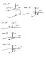
- FIG. 1 and 2Displacement velocity profiles for both spring driven and cam driven tissue penetration devices are shown in FIG. 1 and 2 , respectively.
- Velocityis plotted against displacement X of the lancet.
- FIG. 1represents a displacement/velocity profile typical of spring driven devices.
- the lancet exit velocityincreases until the lancet hits the surface of the skin 10. Because of the tensile characteristics of the skin, it will bend or deform until the lancet tip cuts the surface 20, the lancet will then penetrate the skin until it reaches a full stop 30. At this point displacement is maximal and reaches a limit of penetration and the lancet stops. Mechanical stops absorb excess energy from the driver and transfer it to the lancet.
- the energy stored in the springcan cause recoil resulting in multiple piercing as seen by the coiled profile in FIG. 1 . This results in unnecessary pain from the additional tissue penetration as well as from transferring vibratory energy into the skin and exciting nerve endings. Retraction of the lancet then occurs and the lancet exits the skin 40 to return into the housing. Velocity cannot be controlled in any meaningful way for this type of spring-powered driver.
- FIG. 2shows a displacement/velocity profile for a cam driven driver, which is similar to that of FIG. 1 , but because the return path is specified in the cam configuration, there is no possibility of multiple tissue penetrations from one actuation.
- Cam based driverscan offer some level of control of lancet velocity vs. displacement, but not enough to achieve many desirable displacement/velocity profiles.
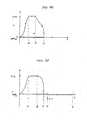
- controllable force driverto drive a lancet, such as a driver, powered by electromagnetic energy.
- a controllable drivercan achieve a desired velocity versus position profile, such as that shown in FIG. 3 .
- These controllable driversallow for the ability to accurately control depth of penetration, to control lancet penetration and withdrawal velocity, and therefore reduce the pain perceived when cutting into the skin.
- Embodiments of the inventioninclude a controllable driver that can be used with a feedback loop with a position sensor to control the power delivered to the lancet, which can optimize the velocity and displacement profile to compensate for variations in skin thickness
- Pain reductioncan be achieved by using a rapid lancet cutting speed, which is facilitated by the use of a lightweight lancet.
- the rapid cuttingminimizes the shock waves produced when the lancet strikes the skin in addition to compressing the skin for efficient cutting. If a controllable driver is used, the need for a mechanical stop can be eliminated. Due to the very light mass of the lancet and lack of a mechanical stop, there is little or no vibrational energy transferred to the finger during cutting.
- the lancing devicessuch as those whose velocity versus position profiles are shown in FIGS. 1 and 2 typically yield 50% spontaneous blood.
- some lancing eventsare unsuccessful and yield no blood, even on milking the finger.
- a spontaneous blood droplet generationis dependent on reaching the blood capillaries and venuoles, which yield the blood sample. It is therefore an issue of correct depth of penetration of the cutting device. Due to variations in skin thickness and hydration, some types of skin will deform more before cutting starts, and hence the actual depth of penetration will be less, resulting in less capillaries and venuoles cut.
- a controllable force drivercan control the depth of penetration of a lancet and hence improve the spontaneity of blood yield. Furthermore, the use of a controllable force driver can allow for slow retraction of the lancet (slower than the cutting velocity) resulting in improved success rate due to the would channel remaining open for the free passage of blood to the surface of the skin.
- Spontaneous blood yieldoccurs when blood from the cut vessels flow up the wound tract to the surface of the skin, where it can be collected and tested. Tissue elasticity parameters may force the wound tract to close behind the retracting lancet preventing the blood from reaching the surface. If however, the lancet were to be withdrawn slowly from the wound tract, thus keeping the wound open, blood could flow up the patent channel behind the tip of the lancet as it is being withdrawn (ref. FIGS. 10 and 11 ). Hence the ability to control the lancet speed into and out of the wound allows the device to compensate for changes in skin thickness and variations in skin hydration and thereby achieves spontaneous blood yield with maximum success rate while minimizing pain.
- An electromagnetic drivercan be coupled directly to the lancet minimizing the mass of the lancet and allowing the driver to bring the lancet to a stop at a predetermined depth without the use of a mechanical stop. Alternatively, if a mechanical stop is required for positive positioning, the energy transferred to the stop can be minimized.
- the electromagnetic driverallows programmable control over the velocity vs. position profile of the entire lancing process including timing the start of the lancet, tracking the lancet position, measuring the lancet velocity, controlling the distal stop acceleration, and controlling the skin penetration depth.
- the tissue penetration deviceincludes a controllable force driver in the form of an electromagnetic driver, which can be used to drive a lancet.
- the term Lancetgenerally includes any sharp or blunt member, preferably having a relatively low mass, used to puncture the skin for the purpose of cutting blood vessels and allowing blood to flow to the surface of the skin.
- Electromagnetic drivergenerally includes any device that moves or drives a tissue penetrating element, such as a lancet under an electrically or magnetically induced force.
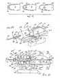
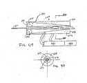
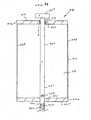
- FIG. 4is a partially exploded view of an example of an electromagnetic driver. The top half of the driver is shown assembled. The bottom half of the driver is shown exploded for illustrative purposes.
- FIG. 4shows the inner insulating housing 22 separated from the stationary housing or PC board 20, and the lancet 24 and flag 26 assembly separated from the inner insulating housing 22 for illustrative purposes.
- only four rivets 18are shown as attached to the inner insulating housing 22 and separated from the PC board 20.
- each coil drive field core in the PC board located in the PC Board 20 and 30is connected to the inner insulating housing 22 and 32 with rivets.
- the electromagnetic driverhas a moving part comprising a lancet assembly with a lancet 24 and a magnetically permeable flag 26 attached at the proximal or drive end and a stationary part comprising a stationary housing assembly with electric field coils arranged so that they produce a balanced field at the flag to reduce or eliminate any net lateral force on the flag.
- the electric field coilsare generally one or more metal coils, which generate a magnetic field when electric current passes through the coil.
- the iron flagis a flat or enlarged piece of magnetic material, which increases the surface area of the lancet assembly to enhance the magnetic forces generated between the proximal end of the lancet and a magnetic field produced by the field coils. The combined mass of the lancet and the iron flag can be minimized to facilitate rapid acceleration for introduction into the skin of a patient, to reduce the impact when the lancet stops in the skin, and to facilitate prompt velocity profile changes throughout the sampling cycle.
- the stationary housing assemblyconsists of a PC board 20, a lower inner insulating housing 22, an upper inner insulating housing 32, an upper PC board 30, and rivets 18 assembled into a single unit.
- the lower and upper inner insulating housing 22 and 32are relieved to form a slot so that lancet assembly can be slid into the driver assembly from the side perpendicular to the direction of the lancet's advancement and retraction. This allows the disposal of the lancet assembly and reuse of the stationary housing assembly with another lancet assembly while avoiding accidental lancet launches during replacement.
- the electric field coils in the upper and lower stationary housing 20 and 30are fabricated in a multi-layer printed circuit (PC) board. They may also be conventionally wound wire coils.
- PCprinted circuit
- a Teflon® material, or other low friction insulating materialis used to construct the lower and upper inner insulating housing 22 and 32.
- Each insulating housingis mounted on the PC board to provide electrical insulation and physical protection, as well as to provide a low-friction guide for the lancet.
- the lower and upper inner insulating housing 22 and 32provide a reference surface with a small gap so that the lancet assembly 24 and 26 can align with the drive field coils in the PC board for good magnetic coupling.
- Rivets 18connect the lower inner insulating housing 22 to the lower stationary housing 20 and are made of magnetically permeable material such as ferrite or steel, which serves to concentrate the magnetic field. This mirrors the construction of the upper inner insulating housing 32 and upper stationary housing 30. These rivets form the poles of the electric field coils.
- the PC boardis fabricated with multiple layers of coils or with multiple boards. Each layer supports spiral traces around a central hole. Alternate layers spiral from the center outwards or from the edges inward. In this way each layer connects via simple feed-through holes, and the current always travels in the same direction, summing the ampere-turns.
- the PC boards within the lower and upper stationary housings 20 and 30are connected to the lower and upper inner insulating housings 22 and 32 with the rivets 18.
- the lower and upper inner insulating housings 22 and 32expose the rivet heads on opposite ends of the slot where the lancet assembly 24 and 26 travels.
- the magnetic field lines from each rivetcreate magnetic poles at the rivet heads.
- An iron bar on the opposite side of the PC board within each of the lower and upper stationary housing 20 and 30completes the magnetic circuit by connecting the rivets.
- Any fastener made of magnetically permeable materialsuch as iron or steel can be used In place of the rivets.
- a single component made of magnetically permeable material and formed in a horseshoe shapecan be used in place of the rivet/screw and iron bar assembly.
- the magnetically permeable flag 26 attached to the lancet 24is divided into slits and.bars 34.
- the slit patternsare staggered so that coils can drive the flag 26 in two, three or more phases.
- Both lower and upper PC boards 20 and 30contain drive coils so that there is a symmetrical magnetic field above and below the flag 26.
- a magnetic fieldis established around the bars between the slits of the magnetically permeable iron on the flag 26.
- the bars of the flagexperience a force that tends to move the magnetically permeable material to a position minimizing the number and length of magnetic field lines and conducting the magnetic field lines between the magnetic poles.
- a three phase, three-pole design or a shading coil that is offset by one-quarter pitchestablishes the direction of travel.
- the lower and upper PC boards 20 and 30 shown in FIG. 4contain electric field coils, which drive the lancet assembly and the circuitry for controlling the entire electromagnetic driver.
- the example described abovegenerally uses the principles of a magnetic attraction drive, similar to commonly available circular stepper motors ( Hurst Manufacturing BA Series motor, or "Electrical Engineering Handbook” Second edition p 1472-1474, 1997 ).
- Other examplescan include a linear induction drive that uses a changing magnetic field to induce electric currents in the lancet assembly. These induced currents produce a secondary magnetic field that repels the primary field and applies a net force on the lancet assembly.
- the linear induction driveuses an electrical drive control that sweeps a magnetic field from pole to pole, propelling the lancet before it. Varying the rate of the sweep and the magnitude of the field by altering the driving voltage and frequency controls the force applied to the lancet assembly and its velocity.
- the arrangement of the coils and rivets to concentrate the magnetic fluxalso applies to the induction design creating a growing magnetic field as the electric current in the field switches on.
- This growing magnetic fieldcreates an opposing electric current in the conductive flag.
- the flagIn a linear induction motor the flag is electrically conductive, and its magnetic properties are unimportant. Copper or aluminum are materials that can be used for the conductive flags. Copper is generally used because of its good electrical conductivity.
- the opposing electrical fieldproduces an opposing magnetic field that repels the field of the coils.
- a moving fieldcan be generated which pushes the flag along just below the synchronous speed of the coils.
- the flagcan be moved at a desired speed.
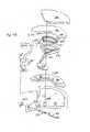
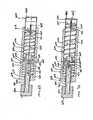
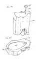
- FIG. 5shows another example of a solenoid type electromagnetic driver that is capable of driving an iron core or slug mounted to the lancet assembly using a direct current (DC) power supply.
- the electromagnetic driverincludes a driver coil pack that is divided into three separate coils along the path of the lancet, two end coils and a middle coil. Direct current is alternated to the coils to advance and retract the lancet.
- the driver coil packis shown with three coils, any suitable number of coils may be used, for example, 4, 5, 6, 7 or more coils may be used.
- the stationary iron housing 40contains the driver coil pack with a first coil 52 flanked by iron spacers 50 which concentrate the magnetic flux at the inner diameter creating magnetic poles.
- the inner insulating housing 48isolates the lancet 42 and iron core 46 from the coils and provides a smooth, low friction guide surface.
- the lancet guide 44further centers the lancet 42 and iron core 46.
- the lancet 42is protracted and retracted by alternating the current between the first coil 52, the middle coil, and the third coil to attract the iron core 46. Reversing the coil sequence and attracting the core and lancet back into the housing retracts the lancet.
- the lancet guide 44also serves as a stop for the iron core 46 mounted to the lancet 42.
- tissue penetration deviceswhich employ spring or cam driving methods have a symmetrical or nearly symmetrical actuation displacement and velocity profiles on the advancement and retraction of the lancet as shown in FIGS. 6 and 7 .
- the stored energydetermines the velocity profile until the energy is dissipated.
- Controlling impact, retraction velocity, and dwell time of the lancet within the tissuecan be useful in order to achieve a high success rate while accommodating variations in skin properties and minimize pain.
- Advantagescan be achieved by taking into account that tissue dwell time is related to the amount of skin deformation as the lancet tries to puncture the surface of the skin and variance in skin deformation from patient to patient based on skin hydration.
- FIG. 8which illustrates a controlled displacement profile
- FIG. 9which illustrates a controlled velocity profile.
- Reduced paincan be achieved by using impact velocities of greater than 2 m/s entry of a tissue penetrating element, such as a lancet, into tissue.
- Retraction of the lancet at a low velocity following the sectioning of the venuole/capillary meshallows the blood to flood the wound tract and flow freely to the surface, thus using the lancet to keep the channel open during retraction as shown in FIGS. 10 and 11 .
- Low-velocity retraction of the lancet near the wound flapprevents the wound flap from sealing off the channel.
- the ability to slow the lancet retractiondirectly contributes to increasing the success rate of obtaining blood.
- Increasing the sampling success rate to near 100%can be important to the combination of sampling and acquisition into an integrated sampling module such as an integrated glucose-sampling module, which incorporates a glucose test strip.
- the lancet and lancet driverare configured so that feedback control is based on lancet displacement, velocity, or acceleration.
- the feedback control information relating to the actual lancet pathis returned to a processor such as that illustrated in FIG. 12 that regulates the energy to the driver, thereby precisely controlling the lancet throughout its advancement and retraction.
- the drivermay be driven by electric current, which includes direct current and alternating current.
- the electromagnetic driver shownis capable of driving an iron core or slug mounted to the lancet assembly using a direct current (DC) power supply and is also capable of determining the position of the iron core by measuring magnetic coupling between the core and the coils.
- the coilscan be used in pairs to draw the iron core into the driver coil pack. As one of the coils is switched on, the corresponding induced current in the adjacent coil can be monitored. The strength of this induced current is related to the degree of magnetic coupling provided by the iron core, and can be used to infer the position of the core and hence, the relative position of the lancet.
- the drive voltagecan be turned off, allowing the coils to relax, and then the cycle is repeated.
- the degree of magnetic coupling between the coilsis converted electronically to a proportional DC voltage that is supplied to an analog-to-digital converter.
- the digitized position signalis then processed and compared to a desired "nominal" position by a central processing unit (CPU).
- the CPUto set the level and/or length of the next power pulse to the solenoid coils uses error between the actual and nominal positions.
- the driver coil packhas three coils consisting of a central driving coil flanked by balanced detection coils built into the driver assembly so that they surround an actuation or magnetically active region with the region centered on the middle coil at mid-stroke.
- a current pulseis applied to the central coil, voltages are induced in the adjacent sense coils. If the sense coils are connected together so that their induced voltages oppose each other, the resulting signal will be positive for deflection from mid-stroke in one direction, negative in the other direction, and zero at mid-stroke.
- This measuring techniqueis commonly used in Linear Variable Differential Transformers (LVDT). Lancet position is determined by measuring the electrical balance between the two sensing coils.
- LVDTLinear Variable Differential Transformers
- a feedback loopcan use a commercially available LED/photo transducer module such as the OPB703 manufactured by Optek Technology, Inc., 1215 W. Crosby Road, Carrollton, Texas, 75006 to determine the distance from the fixed module on the stationary housing to a reflective surface or target mounted on the lancet assembly.
- the LEDacts as a light emitter to send light beams to the reflective surface, which in turn reflects the light back to the photo transducer, which acts as a light sensor. Distances over the range of 4 mm or so are determined by measuring the intensity of the reflected light by the photo transducer.
- a feedback loopcan use a magnetically permeable region on the lancet shaft itself as the core of a Linear Variable Differential Transformer (LVDT).
- LVDTLinear Variable Differential Transformer
- Coil size, number of windings, drive current, signal amplification, and air gap to the permeable regionare specified in the design process.
- the feedback controlsupplies a piezoelectric driver, superimposing a high frequency oscillation on the basic displacement profile.
- the piezoelectric driverprovides improved cutting efficiency and reduces pain by allowing the lancet to "saw” its way into the tissue or to destroy cells with cavitation energy generated by the high frequency of vibration of the advancing edge of the lancet.
- the drive power to the piezoelectric driveris monitored for an impedance shift as the device interacts with the target tissue.
- the resulting force measurement, coupled with the known mass of the lancetis used to determine lancet acceleration, velocity, and position.
- FIG. 12illustrates the operation of a feedback loop using a processor.
- the processor 60stores profiles 62 in non-volatile memory.
- a userinputs information 64 about the desired circumstances or parameters for a lancing event.
- the processor 60selects a driver profile 62 from a set of alternative driver profiles that have been preprogrammed in the processor 60 based on typical or desired tissue penetration device performance determined through testing at the factory or as programmed in by the operator.
- the processor 60may customize by either scaling or modifying the profile based on additional user input information 64. Once the processor has chosen and customized the profile, the processor 60 is ready to modulate the power from the power supply 66 to the lancet driver 68 through an amplifier 70.
- the processor 60measures the location of the lancet 72 using a position sensing mechanism 74 through an analog to digital converter 76. Examples of position sensing mechanisms have been described in the examples above.
- the processor 60calculates the movement of the lancet by comparing the actual profile of the lancet to the predetermined profile.
- the processor 60modulates the power to the lancet driver 68 through a signal generator 78, which controls the amplifier 70 so that the actual profile of the lancet does not exceed the predetermined profile by more than a preset error limit.
- the error limitis the accuracy in the control of the lancet.
- the processor 60can allow the user to rank the results of the lancing event.
- the processor 60stores these results and constructs a database 80 for the individual user.
- the processor 60calculates the profile traits such as degree of painlessness, success rate, and blood volume for various profiles 62 depending on user input information 64 to optimize the profile to the individual user for subsequent lancing cycles. These profile traits depend on the characteristic phases of lancet advancement and retraction.
- the processor 60uses these calculations to optimize profiles 62 for each user.
- an internal clockallows storage in the database 80 of information such as the time of day to generate a time stamp for the lancing event and the time between lancing events to anticipate the user's diurnal needs.
- the databasestores information and statistics for each user and each profile that particular user uses.
- the processor 60can be used to calculate the appropriate lancet diameter and geometry necessary to realize the blood volume required by the user. For example, if the user requires a 1-5 micro liter volume of blood, the processor selects a 200 micron diameter lancet to achieve these results. For each class of lancet, both diameter and lancet tip geometry, is stored in the processor to correspond with upper and lower limits of attainable blood volume based on the predetermined displacement and velocity profiles.
- the lancing deviceis capable of prompting the user for information at the beginning and the end of the lancing event to more adequately suit the user.
- the goalis to either change to a different profile or modify an existing profile.
- the force driving the lancetis varied during advancement and retraction to follow the profile.
- the method of lancing using the lancing devicecomprises selecting a profile, lancing according to the selected profile, determining lancing profile traits for each characteristic phase of the lancing cycle, and optimizing profile traits for subsequent lancing events.
- FIG. 13shows an example of the characteristic phases of lancet advancement and retraction on a graph of force versus time illustrating the force exerted by the lancet driver on the lancet to achieve the desired displacement and velocity profile.
- the characteristic phasesare the lancet introduction phase A-C where the lancet is longitudinally advanced into the skin, the lancet rest phase D where the lancet terminates its longitudinal movement reaching its maximum depth and becoming relatively stationary, and the lancet retraction phase E-G where the lancet is longitudinally retracted out of the skin.
- the duration of the lancet retraction phase E-Gis longer than the duration of the lancet introduction phase A-C, which in turn is longer than the duration of the lancet rest phase D.
- the introduction phasefurther comprises a lancet launch phase prior to A when the lancet is longitudinally moving through air toward the skin, a tissue contact phase at the beginning of A when the distal end of the lancet makes initial contact with the skin, a tissue deformation phase A when the skin bends depending on its elastic properties which are related to hydration and thickness, a tissue lancing phase which comprises when the lancet hits the inflection point on the skin and begins to cut the skin B and the lancet continues cutting the skin C.
- the lancet rest phase Dis the limit of the penetration of the lancet into the skin.
- Painis reduced by minimizing the duration of the lancet introduction phase A-C so that there is a fast incision to a certain penetration depth regardless of the duration of the deformation phase A and inflection point cutting B which will vary from user to user.
- Success rateis increased by measuring the exact depth of penetration from inflection point B to the limit of penetration in the lancet rest phase D. This measurement allows the lancet to always, or at least reliably, hit the capillary beds which are a known distance underneath the surface of the skin.
- the lancet retraction phasefurther comprises a primary retraction phase E when the skin pushes the lancet out of the wound tract, a secondary retraction phase F when the lancet starts to become dislodged and pulls in the opposite direction of the skin, and lancet exit phase G when the lancet becomes free of the skin.
- Primary retractionis the result of exerting a decreasing force to pull the lancet out of the skin as the lancet pulls away from the finger.
- Secondary retractionis the result of exerting a force in the opposite direction to dislodge the lancet. Control is necessary to keep the wound tract open as blood flows up the wound tract.
- Blood volumeis increased by using a uniform velocity to retract the lancet during the lancet retraction phase E-G regardless of the force required for the primary retraction phase E or secondary retraction phase F, either of which may vary from user to user depending on the properties of the user's skin.
- FIG. 14shows a standard industry lancet for glucose testing which has a three-facet geometry. Taking a rod of diameter 114 and grinding 8 degrees to the plane of the primary axis to create the primary facet 110 produces the lancet 116. The secondary facets 112 are then created by rotating the shaft of the needle 15 degrees, and then rolling over 12 degrees to the plane of the primary facet. Other possible geometry's require altering the lancet's production parameters such as shaft diameter, angles, and translation distance.
- FIG. 15illustrates facet and tip geometry 120 and 122, diameter 124, and depth 126 which are significant factors in reducing pain, blood volume and success rate. It is known that additional cutting by the lancet is achieved by increasing the shear percentage or ratio of the primary to secondary facets, which when combined with reducing the lancet's diameter reduces skin tear and penetration force and gives the perception of less pain. Overall success rate of blood yield, however, also depends on a variety of factors, including the existence of facets, facet geometry, and skin anatomy.
- FIG. 16shows another example of displacement versus time profile of a lancet for a controlled lancet retraction.
- FIG. 17shows the velocity vs. time profile of the lancet for the controlled retraction of FIG. 16 .
- the lancet drivercontrols lancet displacement and velocity at several steps in the lancing cycle, including when the lancet cuts the blood vessels to allow blood to pool 130, and as the lancet retracts, regulating the retraction rate to allow the blood to flood the wound tract while keeping the wound flap from sealing the channel 132 to permit blood to exit the wound.
- FIG. 18shows the use of a tissue penetration device, which includes a retractable coil on the lancet tip.
- a coiled helix or tube 140is attached externally to lancet 116 with the freedom to slide such that when the lancet penetrates the skin 150, the helix or tube 140 follows the trajectory of the lancet 116.
- the helixbegins the lancing cycle coiled around the facets and shaft of the lancet 144. As the lancet penetrates the skin, the helix braces the wound tract around the lancet 146.
- the helixAs the lancet retracts, the helix remains to brace open the wound tract, keeping the wound tract from collapsing and keeping the surface skin flap from closing 148. This allows blood 152 to pool and flow up the channel to the surface of the skin. The helix is then retracted as the lancet pulls the helix to the point where the helix is decompressed to the point where the diameter of the helix becomes less than the diameter of the wound tract and becomes dislodged from the skin.
- the tube or helix 140is made of wire or metal of the type commonly used in angioplasty stents such as stainless steel, nickel titanium alloy or the like.
- the tube or helix 140 or a ringcan be made of a biodegradable material, which braces the wound tract by becoming lodged in the skin. Biodegradation is completed within seconds or minutes of insertion, allowing adequate time for blood to pool and flow up the wound tract. Biodegradation is activated by heat, moisture, or pH from the skin.
- the woundcould be held open by coating the lancet with a powder or other granular substance.
- the powdercoats the wound tract and keeps it open when the lancet is withdrawn.
- the powder or other granular substancecan be a coarse bed of microspheres or capsules which hold the channel open while allowing blood to flow through the porous interstices.
- the woundcan be held open using a two-part needle, the outer part in the shape of a "U” and the inner part filling the "U.” After creating the wound the inner needle is withdrawn leaving an open channel, rather like the plugs that are commonly used for withdrawing sap from maple trees.
- FIG. 19shows a further example of a method and device for facilitating blood flow utilizing an elastomer to coat the wound.
- This methoduses an elastomer 154, such as silicon rubber, to coat or brace the wound tract 156 by covering and stretching the surface of the finger 158.
- the elastomer 154is applied to the finger 158 prior to lancing. After a short delay, the lancet (not shown) then penetrates the elastomer 154 and the skin on the surface of the finger 158 as is seen in 160. Blood is allowed to pool and rise to the surface while the elastomer 154 braces the wound tract 156 as is seen in 162 and 164.
- Other known mechanisms for increasing the success rate of blood yield after lancingcan include creating a vacuum, suctioning the wound, applying an adhesive strip, vibration while cutting, or initiating a second lance if the first is unsuccessful.
- FIG. 20illustrates a tissue penetration device which may be used in combination with the sampling modules of the present invention, more specifically, a lancing device 180 that includes a controllable driver 179 coupled to a tissue penetration element.
- the lancing device 180has a proximal end 181 and a distal end 182.
- the tissue penetration elementin the form of a lancet 183, which is coupled to an elongate coupler shaft 184 by a drive coupler 185.
- the elongate coupler shaft 184has a proximal end 186 and a distal end 187.
- a driver coil pack 188is disposed about the elongate coupler shaft 184 proximal of the lancet 183.
- a position sensor 191is disposed about a proximal portion 192 of the elongate coupler shaft 184 and an electrical conductor 194 electrically couples a processor 193 to the position sensor 191.
- the elongate coupler shaft 184 driven by the driver coil pack 188 controlled by the position sensor 191 and processor 193form the controllable driver, specifically, a controllable electromagnetic driver.
- the lancet 183has a proximal end 195 and a distal end 196 with a sharpened point at the distal end 196 of the lancet 183 and a drive head 198 disposed at the proximal end 195 of the lancet 183.
- a lancet shaft 201is disposed between the drive head 198 and the sharpened point 197.
- the lancet shaft 201may be comprised of stainless steel, or any other suitable material or alloy and have a transverse dimension of about 0.1 to about 0.4 mm.
- the lancet shaftmay have a length of about 3 mm to about 50 mm, specifically, about 15 mm to about 20 mm.
- the drive head 198 of the lancet 183is an enlarged portion having a transverse dimension greater than a transverse dimension of the lancet shaft 201 distal of the drive head 198. This configuration allows the drive head 198 to be mechanically captured by the drive coupler 185.
- the drive head 198may have a transverse dimension of about 0.5 to about 2 mm.
- a magnetic member 202is secured to the elongate coupler shaft 184 proximal of the drive coupler 185 on a distal portion 203 of the elongate coupler shaft 184.
- the magnetic member 202is a substantially cylindrical piece of magnetic material having an axial lumen 204 extending the length of the magnetic member 202.
- the magnetic member 202has an outer transverse dimension that allows the magnetic member 202 to slide easily within an axial lumen 205 of a low friction, possibly lubricious, polymer guide tube 205' disposed within the driver coil pack 188.
- the magnetic member 202may have an outer transverse dimension of about 1.0 to about 5.0 mm, specifically, about 2.3 to about 2.5 mm.
- the magnetic member 202may have a length of about 3.0 to about 5.0 mm, specifically, about 4.7 to about 4.9 mm.
- the magnetic member 202can be made from a variety of magnetic materials including ferrous metals such as ferrous steel, iron, ferrite, or the like.
- the magnetic member 202may be secured to the distal portion 203 of the elongate coupler shaft 184 by a variety of methods including adhesive or epoxy bonding, welding, crimping or any other suitable method.
- an optical encoder flag 206is secured to the elongate coupler shaft 184.
- the optical encoder flag 206is configured to move within a slot 207 in the position sensor 191.
- the slot 207 of the position sensor 191is formed between a first body portion 208 and a second body portion 209 of the position sensor 191.
- the slot 207may have separation width of about 1.5 to about 2.0 mm.
- the optical encoder flag 206can have a length of about 14 to about 18 mm, a width of about 3 to about 5 mm and a thickness of about 0.04 to about 0.06 mm.
- the optical encoder flag 206interacts with various optical beams generated by LEDs disposed on or in the position sensor body portions 208 and 209 in a predetermined manner.
- the interaction of the optical beams generated by the LEDs of the position sensor 191generates a signal that indicates the longitudinal position of the optical flag 206 relative to the position sensor 191 with a substantially high degree of resolution.
- the resolution of the position sensor 191may be about 200 to about 400 cycles per inch, specifically, about 350 to about 370 cycles per inch.
- the position sensor 191may have a speed response time (position/time resolution) of 0 to about 120,000 Hz, where one dark and light stripe of the flag constitutes one Hertz, or cycle per second.
- the position of the optical encoder flag 206 relative to the magnetic member 202, driver coil pack 188 and position sensor 191is such that the optical encoder 191 can provide precise positional information about the lancet 183 over the entire length of the lancet's power stroke.
- An optical encoder that is suitable for the position sensor 191is a linear optical incremental encoder, model HEDS 9200, manufactured by Agilent Technologies.
- the model HEDS 9200may have a length of about 20 to about 30 mm, a width of about 8 to about 12 mm, and a height of about 9 to about 11 mm.
- the position sensor 191 illustratedis a linear optical incremental encoder, other suitable position sensors could be used, provided they posses the requisite positional resolution and time response.
- the HEDS 9200is a two channel device where the channels are 90 degrees out of phase with each other. This results in a resolution of four times the basic cycle of the flag. These quadrature outputs make it possible for the processor to determine the direction of lancet travel.
- Other suitable position sensorsinclude capacitive encoders, analog reflective sensors, such as the reflective position sensor discussed above, and the like.
- a coupler shaft guide 211is disposed towards the proximal end 181 of the lancing device 180.
- the guide 211has a guide lumen 212 disposed in the guide 211 to slidingly accept the proximal portion 192 of the elongate coupler shaft 184.
- the guide 211keeps the elongate coupler shaft 184 centered horizontally and vertically in the slot 202 of the optical encoder 191.
- the driver coil pack 188, position sensor 191 and coupler shaft guide 211are all secured to a base 213.
- the base 213is longitudinally coextensive with the driver coil pack 188, position sensor 191 and coupler shaft guide 211.
- the base 213can take the form of a rectangular piece of metal or polymer, or may be a more elaborate housing with recesses, which are configured to accept the various components of the lancing device 180.
- the magnetic member 202is configured to slide within an axial lumen 205 of the driver coil pack 188.
- the driver coil pack 188includes a most distal first coil 214, a second coil 215, which is axially disposed between the first coil 214 and a third coil 216, and a proximal-most fourth coil 217.
- Each of the first coil 214, second coil 215, third coil 216 and fourth coil 217has an axial lumen.
- the axial lumens of the first through fourth coilsare configured to be coaxial with the axial lumens of the other coils and together form the axial lumen 205 of the driver coil pack 188 as a whole.
- Axially adjacent each of the coils 214-217is a magnetic disk or washer 218 that augments completion of the magnetic circuit of the coils 214-217 during a lancing cycle of the device 180.
- the magnetic washers 218 of the example of FIG. 21are made of ferrous steel but could be made of any other suitable magnetic material, such as iron or ferrite.
- the outer shell 189 of the driver coil pack 188is also made of iron or steel to complete the magnetic path around the coils and between the washers 218.
- the magnetic washers 218have an outer diameter commensurate with an outer diameter of the driver coil pack 188 of about 4.0 to about 8.0 mm.
- the magnetic washers 218have an axial thickness of about 0.05, to about 0.4 mm, specifically, about 0.15 to about 0.25 mm.
- the elongate electrical conductor 221is generally an insulated solid copper wire with a small outer transverse dimension of about 0.06 mm to about 0.88 mm, specifically, about 0.3 mm to about 0.5 mm. In one example, 32 gauge copper wire is used for the coils 214-217.
- the number of windings for each of the coils 214-217 of the driver pack 188may vary with the size of the coil, but for some examples each coil 214-217 may have about 30 to about 80 turns, specifically, about 50 to about 60 turns.
- Each coil 214-217can have an axial length of about 1.0 to about 3.0 mm, specifically, about 1.8 to about 2.0 mm.
- Each coil 214-217can have an outer transverse dimension or diameter of about 4.0, to about 2.0 mm, specifically, about 9.0 to about 12.0 mm.
- the axial lumen 205can have a transverse dimension of about 1.0 to about 3.0 mm.
- driver coil 188It may be advantageous in some driver coil 188 examples to replace one or more of the coils with permanent magnets, which produce a magnetic field similar to that of the coils when the coils are activated. In particular, it may be desirable in some examples to replace the second coil 215, the third coil 216 or both with permanent magnets. In addition, it may be advantageous to position a permanent magnet at or near the proximal end of the coil driver pack in order to provide fixed magnet zeroing function for the magnetic member (Adams magnetic Products 23A0002 flexible magnet material (800) 747-7543).
- FIGS. 20 and 21show a permanent bar magnet 219 disposed on the proximal end of the driver coil pack 188.
- the bar magnet 219is arranged so as to have one end disposed adjacent the travel path of the magnetic member 202 and has a polarity configured so as to attract the magnetic member 202 in a centered position with respect to the bar magnet 219.
- the polymer guide tube 205'can be configured to extend proximally to insulate the inward radial surface of the bar magnet 219 from an outer surface of the magnetic member 202. This arrangement allows the magnetic member 219 and thus the elongate coupler shaft 184 to be attracted to and held in a zero point or rest position without the consumption of electrical energy from the power supply 225.
- Having a fixed zero or start point for the elongate coupler shaft 184 and lancet 183can be critical to properly controlling the depth of penetration of the lancet 183 as well as other lancing parameters. This can be because some methods of depth penetration control for a controllable driver measure the acceleration and displacement of the elongate coupler shaft 184 and lancet 183 from a known start position. If the distance of the lancet tip 196 from the target tissue is known, acceleration and displacement of the lancet is known and the start position of the lancet is know, the time and position of tissue contact and depth of penetration can be determined by the processor 193.
- a magnetic bar 219can be used for the purposes discussed above.
- a second permanent bar magnet(not shown) could be added to the proximal end of the driver coil pack 188 with the magnetic fields of the two bar magnets configured to complement each other.
- a disc magnet 219'could be used as illustrated in FIG. 22 .
- Disc magnet 219'is shown disposed at the proximal end of the driver coiled pack 188 with a polymer non-magnetic disc 219" disposed between the proximal-most coil 217 and disc magnet 219' and positions disc magnet 219' away from the proximal end of the proximal-most coil 217.
- the polymer non-magnetic disc spacer 219"is used so that the magnetic member 202 can be centered in a zero or start position slightly proximal of the proximal-most coil 217 of the driver coil pack 188. This allows the magnetic member to be attracted by the proximal-most coil 217 at the initiation of the lancing cycle instead of being passive in the forward drive portion of the lancing cycle.
- An inner lumen of the polymer non-magnetic disc 219"can be configured to allow the magnetic member 202 to pass axially there through while an inner lumen of the disc magnet 219' can be configured to allow the elongate coupler shaft 184 to pass through but not large enough for the magnetic member 202 to pass through. This results in the magnetic member 202 being attracted to the disc magnet 219' and coming to rest with the proximal surface of the magnetic member 202 against a distal surface of the disc magnet 219'. This arrangement provides for a positive and repeatable stop for the magnetic member, and hence the lancet. A similar configuration could also be used for the bar magnet 219 discussed above.
- a magnetic member 202 made of soft ironis attracted to the bar magnet 219 or disc magnet 219'.
- the magnetic field of the driver coil pack 188 and the bar magnet 219 or disc magnet 219', or any other suitable magnetcan be configured such that when the electrical current in the coils 214-217 is turned on, the leakage magnetic field from the coils 214-217 has the same polarity as the bar magnet 219 or disc magnet 219'. This results in a magnetic force that repels the magnetic member 202 from the bar magnet 219 or disc magnet 219' and attracts the magnetic member 202 to the activated coils 214-217.
- the bar magnet 219 or disc magnetthus act to facilitate acceleration of the magnetic member 202 as opposed to working against the acceleration.
- Electrical conductors 222couple the driver coil pack 188 with the processor 193 which can be configured or programmed to control the current flow in the coils 214-217 of the driver coil pack 188 based on position feedback from the position sensor 191, which is coupled to the processor 193 by electrical conductors 194.
- a power source 225is electrically coupled to the processor 193 and provides electrical power to operate the processor 193 and power the coil driver pack 188.
- the power source 225may be one or more batteries that provide direct current power to the 193 processor.
- FIG. 23shows a transverse cross sectional view of drive coupler 185 in more detail.
- the drive head 198 of the lancet 183is disposed within the drive coupler 185 with a first retaining rail 226 and second retaining rail 227 capturing the drive head 198 while allowing the drive head 198 to be inserted laterally into the drive coupler 185 and retracted laterally with minimal mechanical resistance.
- the drive coupler 185may optionally be configured to include snap ridges 228 which allow the drive head 198 to be laterally inserted and retracted, but keep the drive head 198 from falling out of the drive coupler 185 unless a predetermined amount of externally applied lateral force is applied to the drive head 198 of the lancet 183 towards the lateral opening 231 of the drive coupler 185.
- FIG. 27shows an enlarged side view into the coupler opening 231 of the drive coupler 185 showing the snap ridges 228 disposed in the lateral opening 231 and the retaining rails 226 and 227.
- FIG. 28shows an enlarged front view of the drive coupler 185.
- the drive coupler 185can be made from an alloy such as stainless steel, titanium or aluminum, but may also be made from a suitable polymer such as ABS, PVC, polycarbonate plastic or the like.
- the drive couplermay be open on both sides allowing the drive head and lancet to pass through.
- the magnetic member 202is disposed about and secured to the elongate coupler shaft 184.
- the magnetic member 202is disposed within the axial lumen 232 of the fourth coil 217.
- the driver coil pack 188is secured to the base 213.
- the position sensor 191is secured to the base 213 with the first body portion 208 of the position sensor 191 disposed opposite the second body portion 209 of the position sensor 191 with the first and second body portions 208 and 209 of the position sensor 191 separated by the gap or slot 207.
- the elongate coupler shaft 184is slidably disposed within the gap 207 between the first and second body portions 208 and 209 of the position sensor 191.
- the optical encoder flag 206is secured to the elongate coupler shaft 184 and disposed between the first body portion 208 and second body portion 209 of the position sensor 191.
- the proximal portion 192 of the elongate coupler shaft 184is disposed within the guide lumen 212 of the coupler shaft guide 211.
- the guide lumen 212 of the coupler shaft guide 211may be lined with a low friction material such as Teflon® or the like to reduce friction of the elongate coupler shaft 184 during the power stroke of the lancing device 180.
- FIGS. 29A-29Ca flow diagram is shown that describes the operations performed by the processor 193 in controlling the lancet 183 of the lancing device 180 discussed above during an operating cycle.
- FIGS. 30-36illustrate the interaction of the lancet 183 and skin 233 of the patient's finger 234 during an operation cycle of the lancet device 183.
- the processor 193operates under control of programming steps that are stored in an associated memory. When the programming steps are executed, the processor 193 performs operations as described herein. Thus, the programming steps implement the functionality of the operations described with respect to the flow diagram of FIG. 29 .
- the processor 193can receive the programming steps from a program product stored in recordable media, including a direct access program product storage device such as a hard drive or flash ROM, a removable program product storage device such as a floppy disk, or in any other manner known to those of skill in the art.
- the processor 193can also download the programming steps through a network connection or serial connection.
- the processor 193initializes values that it stores in memory relating to control of the lancet, such as variables that it uses to keep track of the controllable driver 179 during movement. For example, the processor may set a clock value to zero and a lancet position value to zero or to some other initial value. The processor 193 may also cause power to be removed from the coil pack 188 for a period of time, such as for about 10 ms, to allow any residual flux to dissipate from the coils.
- the processor 193also causes the lancet to assume an initial stationary position.
- the lancet 183is typically fully retracted such that the magnetic member 202 is positioned substantially adjacent the fourth coil 217 of the driver coil pack 188, shown in FIG. 21 above.
- the processor 193can move the lancet 183 to the initial stationary position by pulsing an electrical current to the fourth coil 217 to thereby attract the magnetic member 202 on the lancet 183 to the fourth coil 217.
- the magnetic membercan be positioned in the initial stationary position by virtue of a permanent magnet, such as bar magnet 219, disc magnet 219' or any other suitable magnet as discussed above with regard to the tissue penetration device illustrated in FIGS. 20 and 21 .
- the processor 193In the next operation, represented by the flow diagram box numbered 247, the processor 193 energizes one or more of the coils in the coil pack 188. This should cause the lancet 183 to begin to move (i.e., achieve a non-zero speed) toward the skin target 233. The processor 193 then determines whether or not the lancet is indeed moving, as represented by the decision box numbered 249. The processor 193 can determine whether the lancet 183 is moving by monitoring the position of the lancet 183 to determine whether the position changes over time.
- the processor 193can monitor the position of the lancet 183 by keeping track of the position of the optical encoder flag 206 secured to the elongate coupler shaft 184 wherein the encoder 191 produces a signal coupled to the processor 193 that indicates the spatial position of the lancet 183.
- the processproceeds to the operation represented by the flow diagram box numbered 253, where the processor deems that an error condition is present.
- the errormay be mechanical, electrical, or software related.
- the lancet 183may be stuck in the stationary position because something is impeding its movement.
- the processproceeds to the operation represented by the flow diagram box numbered 257.
- the processor 193causes the lancet 183 to continue to accelerate and launch toward the skin target 233, as indicated by the arrow 235 in FIG. 30 .
- the processor 193can achieve acceleration of the lancet 183 by sending an electrical current to an appropriate coil 214-217 such that the coil 214-217 exerts an attractive magnetic launching force on the magnetic member 202 and causes the magnetic member 202 and the lancet 183 coupled thereto to move in a desired direction.
- the processor 193can cause an electrical current to be sent to the third coil 216 so that the third coil 216 attracts the magnetic member 202 and causes the magnetic member 202 to move from a position adjacent the fourth coil 217 toward the third coil 216.
- the processorpreferably determines which coil 214-217 should be used to attract the magnetic member 202 based on the position of the magnetic member 202 relative to the coils 214-217. In this manner, the processor 193 provides a controlled force to the lancet that controls the movement of the lancet.
- the processor 193periodically or continually monitors the position and/or velocity of the lancet 183. In keeping track of the velocity and position of the lancet 183 as the lancet 183 moves towards the patient's skin 233 or other tissue, the processor 193 also monitors and adjusts the electrical current to the coils 214-217. In some examples, the processor 193 applies current to an appropriate coil 214-217 such that the lancet 183 continues to move according to a desired direction and acceleration. In the instant case, the processor 193 applies current to the appropriate coil 214-217 that will cause the lancet 183 to continue to move in the direction of the patient's skin 233 or other tissue to be penetrated.
- the processor 193may successively transition the current between coils 214-217 so that as the magnetic member 202 moves past a particular coil 214-217, the processor 193 then shuts off current to that coil 214-217 and then applies current to another coil 214-217 that will attract the magnetic member 202 and cause the magnetic member 202 to continue to move in the desired direction.
- the processor 193can take into account various factors, including the speed of the lancet 183, the position of the lancet 183 relative to the coils 214-217, the number of coils 214-217, and the level of current to be applied to the coils 214-217 to achieve a desired speed or acceleration.
- the processor 193determines whether the cutting or distal end tip 196 of the lancet 183 has contacted the patient's skin 233, as shown in FIG. 31 and as represented by the decision box numbered 265 in FIG. 29B .
- the processor 193may determine whether the lancet 183 has made contact with the target tissue 233 by a variety of methods, including some that rely on parameters which are measured prior to initiation of a lancing cycle and other methods that are adaptable to use during a lancing cycle without any predetermined parameters.
- the processor 193determines that the skin has been contacted when the end tip 196 of the lancet 183 has moved a predetermined distance with respect to its initial position. If the distance from the tip 961 of the lancet 183 to the target tissue 233 is known prior to initiation of lancet 183 movement, the initial position of the lancet 183 is fixed and known, and the movement and position of the lancet 183 can be accurately measured during a lancing cycle, then the position and time of lancet contact can be determined.
- This methodrequires an accurate measurement of the distance between the lancet tip 196 and the patient's skin 233 when the lancet 183 is in the zero time or initial position. This can be accomplished in a number of ways. One way is to control all of the mechanical parameters that influence the distance from the lancet tip 196 to the patient's tissue or a surface of the lancing device 180 that will contact the patient's skin 233. This could include the start position of the magnetic member 202, magnetic path tolerance, magnetic member 202 dimensions, driver coil pack 188 location within the lancing device 180 as a whole, length of the elongate coupling shaft 184, placement of the magnetic member 202 on the elongate coupling shaft 184, length of the lancet 183 etc.
- the distance from the lancet tip 196 to the target tissue 233can be determined at the time of manufacture of the lancing device 180. The distance could then be programmed into the memory of the processor 193. If an adjustable feature is added to the lancing device 180, such as an adjustable length elongate coupling shaft 184, this can accommodate variations in all of the parameters noted above, except length of the lancet 183.
- An electronic alternative to this mechanical approachwould be to calibrate a stored memory contact point into the memory of the processor 193 during manufacture based on the mechanical parameters described above.
- moving the lancet tip 196 to the target tissue 233 very slowly and gently touching the skin 233 prior to actuationcan accomplish the distance from the lancet tip 196 to the tissue 233.
- the position sensorcan accurately measure the distance from the initialization point to the point of contact, where the resistance to advancement of the lancet 183 stops the lancet movement.
- the lancet 183is then retracted to the initialization point having measured the distance to the target tissue 233 without creating any discomfort to the user.
- the processor 193may use software to determine whether the lancet 183 has made contact with the patient's skin 233 by measuring for a sudden reduction in velocity of the lancet 183 due to friction or resistance imposed on the lancet 183 by the patient's skin 233.
- the optical encoder 191measures displacement of the lancet 183.
- the position output dataprovides input to the interrupt input of the processor 193.
- the processor 193also has a timer capable of measuring the time between interrupts. The distance between interrupts is known for the optical encoder 191, so the velocity of the lancet 183 can be calculated by dividing the distance between interrupts by the time between the interrupts.
- This methodrequires that velocity losses to the lancet 183 and elongate coupler 184 assembly due to friction are known to an acceptable level so that these velocity losses and resulting deceleration can be accounted for when establishing a deceleration threshold above which contact between lancet tip 196 and target tissue 233 will be presumed.
- This same conceptcan be implemented in many ways. For example, rather than monitoring the velocity of the lancet 183, if the processor 193 is controlling the lancet driver in order to maintain a fixed velocity, the power to the driver 188 could be monitored. If an amount of power above a predetermined threshold is required in order to maintain a constant velocity, then contact between the tip of the lancet 196 and the skin 233 could be presumed.
- the processor 193determines skin 233 contact by the lancet 183 by detection of an acoustic signal produced by the tip 196 of the lancet 183 as it strikes the patient's skin 233. Detection of the acoustic signal can be measured by an acoustic detector 236 placed in contact with the patient's skin 233 adjacent a lancet penetration site 237, as shown in FIG. 31 . Suitable acoustic detectors 236 include piezo electric transducers, microphones and the like. The acoustic detector 236 transmits an electrical signal generated by the acoustic signal to the processor 193 via electrical conductors 238.
- contact of the lancet 183 with the patient's skin 233can be determined by measurement of electrical continuity in a circuit that includes the lancet 183, the patient's finger 234 and an electrical contact pad 240 that is disposed on the patient's skin 233 adjacent the contact site 237 of the lancet 183, as shown in FIG. 31 .
- the circuit 239is completed and current flows through the circuit 239. Completion of the circuit 239 can then be detected by the processor 193 to confirm skin 233 contact by the lancet 183.
- the processproceeds to a timeout operation, as represented by the decision box numbered 267 in FIG. 29B .
- the processor 193waits a predetermined time period. If the timeout period has not yet elapsed (a "No" outcome from the decision box 267), then the processor continues to monitor whether the lancet has contacted the target skin 233. The processor 193 preferably continues to monitor the position and speed of the lancet 183, as well as the electrical current to the appropriate coil 214-217 to maintain the desired lancet 183 movement.
- the processproceeds to a withdraw phase, where the lancet is withdrawn away from the skin 233, as discussed more fully below.
- the lancet 183may not have contacted the target skin 233 for a variety of reasons, such as if the patient removed the skin 233 from the lancing device or if something obstructed the lancet 183 prior to it contacting the skin.
- the processor 193may also proceed to the withdraw phase prior to skin contact for other reasons. For example, at some point after initiation of movement of the lancet 183, the processor 193 may determine that the forward acceleration of the lancet 183 towards the patient's skin 233 should be stopped or that current to all coils 214-217 should be shut down. This can occur, for example, if it is determined that the lancet 183 has achieved sufficient forward velocity, but has not yet contacted the skin 233.
- the average penetration velocity of the lancet 183 from the point of contact with the skin to the point of maximum penetrationmay be about 2.0 to about 10.0 m/s, specifically, about 3.8 to about 4.2 m/s.
- the average penetration velocity of the lancetmay be from about 2 to about 8 meters per second, specifically, about 2 to about 4 m/s.
- the processor 193can also proceed to the withdraw phase if it is determined that the lancet 183 has fully extended to the end of the power stroke of the operation cycle of lancing procedure. In other words, the process may proceed to withdraw phase when an axial center 241 of the magnetic member 202 has moved distal of an axial center 242 of the first coil 214 as show in FIG. 21 . In this situation, any continued power to any of the coils 214-217 of the driver coil pack 188 serves to decelerate the magnetic member 202 and thus the lancet 183. In this regard, the processor 193 considers the length of the lancet 183 (which can be stored in memory) the position of the lancet 183 relative to the magnetic member 202, as well as the distance that the lancet 183 has traveled.
- the processor 193determines that the lancet 183 has contacted the skin 233 (a "Yes" outcome from the decision box 265), then the processor 193 can adjust the speed of the lancet 183 or the power delivered to the lancet 183 for skin penetration to overcome any frictional forces on the lancet 183 in order to maintain a desired penetration velocity of the lancet.
- the flow diagram box numbered 267represents this.
- the distal tip 196 of the lancet 183will first begin to depress or tent the contacted skin 237 and the skin 233 adjacent the lancet 183 to form a tented portion 243 as shown in FIG. 32 and further shown in FIG. 33 .
- the lancet 183will eventually begin to penetrate the skin 233, as shown in FIG. 34 .
- the static force at the distal tip 196 of the lancet 183 from the skin 233will become a dynamic cutting force, which is generally less than the static tip force.
- the processor 193determines whether the distal end 196 of the lancet 183 has reached a brake depth.
- the brake depthis the skin penetration depth for which the processor 193 determines that deceleration of the lancet 183 is to be initiated in order to achieve a desired final penetration depth 244 of the lancet 183 as show in FIG. 35 .
- the brake depthmay be pre-determined and programmed into the processor's memory, or the processor 193 may dynamically determine the brake depth during the actuation.
- the amount of penetration of the lancet 183 in the skin 233 of the patientmay be measured during the operation cycle of the lancet device 180.
- the penetration depth necessary for successfully obtaining a useable samplecan depend on the amount of tenting of the skin 233 during the lancing cycle.
- the amount of tenting of the patient's skin 233can in turn depend on the tissue characteristics of the patient such as elasticity, hydration etc. A method for determining these characteristics is discussed below with regard to skin 233 tenting measurements during the lancing cycle and illustrated in FIGS. 37-41 .
- Penetration measurementcan be carried out by a variety of methods that are not dependent on measurement of tenting of the patient's skin.
- the penetration depth of the lancet 183 in the patient's skin 233is measured by monitoring the amount of capacitance between the lancet 183 and the patient's skin 233.
- a circuitincludes the lancet 183, the patient's finger 234, the processor 193 and electrical conductors connecting these elements.
- the lancet 183penetrates the patient's skin 233, the greater the amount of penetration, the greater the surface contact area between the lancet 183 and the patient's skin 233.
- the increased capacitancecan be easily measured by the processor 193 using methods known in the art and penetration depth can then be correlated to the amount of capacitance.
- the same methodcan be used by measuring the electrical resistance between the lancet 183 and the patient's skin.
- the processor 193waits a predetermined time period. If the timeout period has not yet elapsed (a "No" outcome from the decision box 273), then the processor continues to monitor whether the brake depth has been reached. If the timeout period elapses without the lancet 183 achieving the brake depth (a "Yes" output from the decision box 273), then the processor 193 deems that the lancet 183 will not reach the brake depth and the process proceeds to the withdraw phase, which is discussed more fully below. This may occur, for example, if the lancet 183 is stuck at a certain depth.
- the processproceeds to the operation represented by the flow diagram box numbered 275.
- the processor 193causes a braking force to be applied to the lancet to thereby reduce the speed of the lancet 183 to achieve a desired amount of final skin penetration depth 244, as shown in FIG. 26 .
- FIGS. 32 and 33illustrate the lancet making contact with the patient's skin and deforming or depressing the skin prior to any substantial penetration of the skin.
- the speed of the lancet 183is preferably reduced to a value below a desired threshold and is ultimately reduced to zero.
- the processor 193can reduce the speed of the lancet 183 by causing a current to be sent to a 214-217 coil that will exert an attractive braking force on the magnetic member 202 in a proximal direction away from the patient's tissue or skin 233, as indicated by the arrow 290 in FIG. 36 . Such a negative force reduces the forward or distally oriented speed of the lancet 183.
- the processor 193can determine which coil 214-217 to energize based upon the position of the magnetic member 202 with respect to the coils 214-217 of the driver coil pack 188, as indicated by the position sensor 191.
- the processproceeds to the withdraw phase, as represented by the flow diagram box numbered 277.
- the withdraw phasebegins with the operation represented by the flow diagram box numbered 279 in FIG. 29C .
- the processor 193allows the lancet 183 to settle at a position of maximum skin penetration 244, as shown in FIG. 35 .
- the processor 193waits until any motion in the lancet 183 (due to vibration from impact and spring energy stored in the skin, etc.) has stopped by monitoring changes in position of the lancet 183.
- the processor 193preferably waits until several milliseconds (ms), such as on the order of about 8 ms, have passed with no changes in position of the lancet 183.
- the lancetmay be allowed to settle for about 1 to about 2000 milliseconds, specifically, about 50 to about 200 milliseconds.
- the settling timemay be about 1 to about 200 milliseconds.
- FIGS. 37-41a lancet 183 is illustrated in various phases of a lancing cycle with target tissue 233.
- FIG. 37shows tip 196 of lancet 183 making initial contact with the skin 233 at the point of initial impact.
- FIG. 38illustrates an enlarged view of the lancet 183 making initial contact with the tissue 233 shown in FIG. 37 .
- the lancet tip 196has depressed or tented the skin 233 prior to penetration over a distance of X, as indicated by the arrow labeled X in FIG. 39 .
- the lancet 183has reached the full length of the cutting power stroke and is at maximum displacement. In this position, the lancet tip 196 has penetrated the tissue 233 a distance of Y, as indicated by the arrow labeled Y in FIG. 39 .
- FIG. 38illustrates an enlarged view of the lancet 183 making initial contact with the tissue 233 shown in FIG. 37 .
- the lancet tip 196was displaced a total distance of X plus Y from the time initial contact with the skin 233 was made to the time the lancet tip 196 reached its maximum extension as shown in FIG. 40 .
- the lancet tip 196has only penetrated the skin 233 a distance Y because of the tenting phenomenon.
- the processor 193allows the lancet to settle for about 8 msec. It is during this settling time that the skin 233 rebounds or relaxes back to approximately its original configuration prior to contact by the lancet 183 as shown in FIG. 41 .
- the lancet tip 196is still buried in the skin to a depth of Y, as shown in FIG. 41 , however the elastic recoil of the tissue has displaced the lancet rearward or retrograde to the point of inelastic tenting that is indicated by the arrows Z in FIG. 41 .
- the processorreads and stores the position data generated by the position sensor 191 and thus measures the amount of elastic tenting, which is the difference between X and Z.
- FIG. 42shows both a velocity versus time graph and a position versus time graph of a lancet tip 196 during a lancing cycle that includes elastic and inelastic tenting.
- FIG. 42shows both a velocity versus time graph and a position versus time graph of a lancet tip 196 during a lancing cycle that includes elastic and inelastic tenting.
- the lancet 183is being accelerated from the initialization position or zero position.
- point Bthe lancet is in ballistic or coasting mode, with no additional power being delivered.
- the lancet tip 196contacts the tissue 233 and begins to tent the skin 233 until it reaches a displacement C.
- the amount of inelastic tenting indicated by Ztends to be fairly consistent and small compared to the magnitude of the elastic tenting.
- the amount of inelastic tenting Zcan be about 120 to about 140 microns.
- the value for the total amount of tenting for the penetration stroke of the lancet 183is effectively equal to the rearward displacement of the lancet during the settling phase as measured by the processor 193 plus a predetermined value for the inelastic recoil, such as 130 microns.
- Inelastic recoilfor some examples can be about 100 to about 200 microns.
- the ability to measure the magnitude of skin 233 tenting for a patientis important to controlling the depth of penetration of the lancet tip 196 as the skin is generally known to vary in elasticity and other parameters due to age, time of day, level of hydration, gender and pathological state.
- This value for total tenting for the lancing cyclecan then be used to determine the various characteristics of the patient's skin 233. Once a body of tenting data is obtained for a given patient, this data can be analyzed in order to predict the total lancet displacement, from the point of skin contact, necessary for a successful lancing procedure. This enables the tissue penetration device to achieve a high success rate and minimize pain for the user.
- a rolling average tablecan be used to collect and store the tenting data for a patient with a pointer to the last entry in the table. When a new entry is input, it can replace the entry at the pointer and the pointer advances to the next value. When an average is desired, all the values are added and the sum divided by the total number of entries by the processor 193. Similar techniques involving exponential decay (multiply by .95, add 0.05 times current value, etc.) are also possible.
- FIG. 43shows a cross sectional view of the layers of the skin 233.
- the stratum corneumis typically about 0.1 to about 0.6 mm thick and the distance from the top of the dermis to the venuole plexus can be from about 0.3 to about 1.4 mm.
- Elastic tentingcan have a magnitude of up to about 2 mm or so, specifically, about 0.2 to about 2.0 mm, with an average magnitude of about 1 mm.
- the amount of lancet displacement necessary to overcome the tentingcan have a magnitude greater than the thickness of skin necessary to penetrate in order to reach the venuolar plexus.
- the total lancet displacement from point of initial skin contactmay have an average value of about 1.7 to about 2.1 mm.
- penetration depth and maximum penetration depthmay be about 0.5 mm to about 5 mm, specifically, about 1 mm to about 3 mm. In some examples, a maximum penetration depth of about 0.5 to about 3 mm is useful.
- the processor 193causes a withdraw force to be exerted on the lancet 183 to retract the lancet 183 from the skin 233, as shown by arrow 290 in FIG. 36
- the processor 193sends a current to an appropriate coil 214-217 so that the coil 214-217 exerts an attractive distally oriented force on the magnetic member 202, which should cause the lancet 183 to move backward in the desired direction.
- the lancet 183is withdrawn with less force and a lower speed than the force and speed during the penetration portion of the operation cycle.
- Withdrawal speed of the lancet in some examplescan be about 0.004 to about 0.5 m/s, specifically, about 0.006 to about 0.01 m/s.
- useful withdrawal velocitiescan be about 0.001 to about 0.02 meters per second, specifically, about 0.001 to about 0.01 meters per second.
- the withdrawal velocitymay up to about 0.02 meters per second.
- a ratio of the average penetration velocity relative to the average withdrawal velocitycan be about 100 to about 1000.
- a withdrawal velocity of about 2 to about 10 meters per secondmay be used.
- the processor 193determines whether the lancet 183 is moving in the desired backward direction as a result of the force applied, as represented by the decision box numbered 281. If the processor 193 determines that the lancet 183 is not moving (a "No" result from the decision box 281), then the processor 193 continues to cause a force to be exerted on the lancet 183, as represented by the flow diagram box numbered 282. The processor 193 may cause a stronger force to be exerted on the lancet 183 or may just continue to apply the same amount of force. The processor then again determines whether the lancet is moving, as represented by the decision box numbered 283.
- the processor 193determines that an error condition is present, as represented by the flow diagram box numbered 284. In such a situation, the processor preferably de-energizes the coils to remove force from the lancet, as the lack of movement may be an indication that the lancet is stuck in the skin of the patient and, therefore, that it may be undesirable to continue to attempt pull the lancet out of the skin.
- the processproceeds to the operation represented by the flow diagram box numbered 285.
- the backward movement of the lancet 183continues until the lancet distal end has been completely withdrawn from the patient's skin 233.
- the lancet 183is withdrawn with less force and a lower speed than the force and speed during the penetration portion of the operation cycle.
- the relatively slow withdrawal of the lancet 183may allow the blood from the capillaries of the patient accessed by the lancet 183 to follow the lancet 183 during withdrawal and reach the skin surface to reliably produce a usable blood sample. The process then ends.
- Controlling the lancet motion over the operating cycle of the lancet 183 as discussed aboveallows a wide variety of lancet velocity profiles to be generated by the lancing device 180.
- any of the lancet velocity profiles discussed above with regard to other examplescan be achieved with the processor 193, position sensor 191 and driver coil pack 188 of the lancing device 180.
- FIGS. 44 and 45illustrates a lancet profile with a fast entry velocity and a slow withdrawal velocity.
- FIG. 44illustrates a lancing profile showing velocity of the lancet versus position. The lancing profile starts at zero time and position and shows acceleration of the lancet towards the tissue from the electromagnetic force generated from the electromagnetic driver.
- the poweris shut off and the lancet 183 begins to coast until it reaches the skin 233 indicated by B at which point, the velocity begins to decrease.
- the lancet 183has reached maximum displacement and settles momentarily, typically for a time of about 8 milliseconds.
- a retrograde withdrawal forceis then imposed on the lancet by the controllable driver, which is controlled by the processor to maintain a withdrawal velocity of no more than about 0.006 to about 0.01 meters/second.
- the same cycleis illustrated in the velocity versus time plot of FIG. 45 where the lancet is accelerated from the start point to point A.
- the lancet 183coasts from A to B where the lancet tip 196 contacts tissue 233.
- the lancet tip 196then penetrates the tissue and slows with braking force eventually applied as the maximum penetration depth is approached.
- the lancetis stopped and settling between C and D.
- the withdrawal phasebegins and the lancet 183 is slowly withdrawn until it returns to the initialization point shown by E in FIG. 45 .
- retrograde recoil from elastic and inelastic tentingwas not shown in the lancing profiles of FIGS. 44 and 45 for purpose of illustration and clarity.
- the withdrawal phasemay use a dual speed profile, with the slow .006 to .01 meter per second speed used until the lancet is withdrawn past the contact point with the tissue, then a faster speed of .01 to 1 meters per second may be used to shorten the complete cycle.
- the lancet 297has a proximal end 298 and a distal end 299 with a sharpened point at the distal end 299 of the lancet 297.
- a magnetic member 301disposed about and secured to a proximal end portion 302 of the lancet 297 with a lancet shaft 303 being disposed between the magnetic member 301 and the sharpened point 299.
- the lancet shaft 303may be comprised of stainless steel, or any other suitable material or alloy.
- the lancet shaft 303may have a length of about 3 mm to about 50 mm specifically, about 5 mm to about 15 mm.
- the magnetic member 301is configured to slide within an axial lumen 304 of the driver coil pack 295.
- the driver coil pack 295includes a most distal first coil 305, a second coil 306, which is axially disposed between the first coil 305 and a third coil 307, and a proximal-most fourth coil 308.
- Each of the first coil 305, second coil 306, third coil 307 and fourth coil 308has an axial lumen.
- the axial lumens of the first through fourth coils 305-308are configured to be coaxial with the axial lumens of the other coils and together form the axial lumen 309 of the driver coil pack 295 as a whole.
- Axially adjacent each of the coils 305-308is a magnetic disk or washer 310 that augments completion of the magnetic circuit of the coils 305-308 during a lancing cycle of the driven coil pack 295.
- the magnetic washers 310 of the example of FIG. 46are made of ferrous steel but could be made of any other suitable magnetic material, such as iron or ferrite.
- the magnetic washers 310have an outer diameter commensurate with an outer diameter of the driver coil pack 295 of about 4.0 to about 8.0 mm.
- the magnetic washers 310have an axial thickness of about 0.05, to about 0.4 mm, specifically, about 0.15 to about 0.25 mm.
- the outer shell 294 of the coil packis also made of iron or steel to complete the magnetic path around the coils and between the washers 310.
- the elongate electrical conductor 311is generally an insulated solid copper wire.
- the particular materials, dimensions number of coil windings etc. of the coils 305-308, washers 310 and other components of the driver coil pack 295can be the same or similar to the materials, dimensions number of coil windings etc. of the driver coil pack 188 discussed above.
- Electrical conductors 312couple the driver coil pack 295 with a processor 313 which can be configured or programmed to control the current flow in the coils 305-308 of the driver coil pack 295 based on position feedback from the position sensor 296, which is coupled to the processor 313 by electrical conductors 315.
- a power source 316is electrically coupled to the processor 313 and provides electrical power to operate the processor 313 and power the driver coil pack 295.
- the power source 316may be one or more batteries (not shown) that provide direct current power to the processor 313 as discussed above.
- the position sensor 296is an analog reflecting light sensor that has a light source and light receiver in the form of a photo transducer 317 disposed within a housing 318 with the housing 318 secured in fixed spatial relation to the driver coil pack 295.
- a reflective member 319is disposed on or secured to a proximal end 320 of the magnetic member 301.
- the processor 313determines the position of the lancet 299 by first emitting light from the light source of the photo transducer 317 towards the reflective member 319 with a predetermined solid angle of emission. Then, the light receiver of the photo transducer 317 measures the intensity of light reflected from the reflective member 319 and electrical conductors 315 transmit the signal generated therefrom to the processor 313.
- the position of the lancet 297can thereafter be determined by measuring the intensity of reflected light at any given moment.
- the sensor 296uses a commercially available LED/photo transducer module such as the OPB703 manufactured by Optek Technology, Inc., 1215 W. Crosby Road, Carrollton, Texas, 75006. This method of analog reflective measurement for position sensing can be used for any of the examples of lancet actuators discussed herein.
- any of the lancet actuators or drivers that include coilsmay use one or more of the coils to determine the position of the lancet 297 by using a magnetically permeable region on the lancet shaft 303 or magnetic member 301 itself as the core of a Linear Variable Differential Transformer (LVDT).
- LVDTLinear Variable Differential Transformer
- a flat coil lancet driver 325which has a main body housing 326 and a rotating frame 327.
- the rotating frame 327pivots about an axle 328 disposed between a base 329, a top body portion 330 of the main body housing 326 and disposed in a pivot guide 331 of the rotating frame 327.
- An actuator arm 332 of the rotating frame 327extends radially from the pivot guide 331 and has a linkage receiving opening 333 disposed at an outward end 334 of the actuator arm 332.
- a first end 335 of a coupler linkage 336is coupled to the linkage receiving opening 333 of the actuator arm 332 and can rotate within the linkage receiving opening 333.
- a second end 337 of the coupler linkage 336is disposed within an opening at a proximal end 338 of a coupler translation member 341.
- This configurationallows circumferential forces imposed upon the actuator arm 332 to be transferred into linear forces on a drive coupler 342 secured to a distal end 343 of the coupler translation member 341.
- the materials and dimensions of the drive coupler 342can be the same or similar to the materials and dimensions of the drive coupler 342 discussed above.
- a translation substrate in the form of a coil arm 344extends radially from the pivot guide 331 of the rotating frame 327.
- the coil arm 344is substantially triangular in shape.
- a flat coil 345is disposed on and secured to the coil arm 344.
- the flat coil 345has leading segment 346 and a trailing segment 347, both of which extend substantially orthogonal to the direction of motion of the segments 346 and 347 when the rotating frame 327 is rotating about the pivot guide 331.
- the leading segment 346is disposed within a first magnetically active region 348 generated by a first upper permanent magnet 349 secured to an upper magnet base 351 and a first lower permanent magnet 352 secured to a lower magnet base 353.
- the trailing segment 347is disposed within a second magnetically active region 354 generated by a second upper permanent magnet 355 secured to the upper magnet base 351 and a second lower permanent magnet secured to the lower magnet base 353.
- the magnetic field lines or circuit of the first upper and lower permanent magnets 349, 352, 355 and 356can be directed upward from the first lower permanent magnet 352 to the first upper permanent magnet 349 or downward in an opposite direction.
- the magnetic field lines from the second permanent magnets 355 and 356are also directed up or down, and will have a direction opposite to that of the first upper and lower permanent magnets 349 and 352. This configuration produces rotational force on the coil arm 344 about the pivot guide 331 with the direction of the force determined by the direction of current flow in the flat coil 345.
- a position sensor 357includes an optical encoder disk section 358 is secured to the rotating frame 327 which rotates with the rotating frame 327 and is read by an optical encoder 359 which is secured to the base 329.
- the position sensor 357determines the rotational position of the rotating frame 327 and sends the position information to a processor 360 which can have features which are the same or similar to the features of the processor 193 discussed above via electrical leads 361. Electrical conductor leads 363 of the flat coil 345 are also electrically coupled to the processor 360.
- the rotational forces imposed on the segments 346 and 347are transferred to the rotating frame 327 to the actuator arm 332, through the coupler linkage 336 and coupler translation member 341 and eventually to the drive coupler 342.
- a lancet(not shown) is secured into the drive coupler 342, and the flat coil lancet actuator 325 activated.
- the electrical current in the flat coil 345determines the forces generated on the drive coupler 342, and hence, a lancet secured to the coupler 342.
- the processor 360controls the electrical current in the flat coil 345 based on the position and velocity of the lancet as measured by the position sensor 357 information sent to the processor 360.
- the processor 360is able to control the velocity of a lancet in a manner similar to the processor 193 discussed above and can generate any of the desired lancet velocity profiles discussed above, in addition to others.
- FIGS. 49 and 50depict yet another example of a controlled driver 369 having a driver coil pack 370 for a tissue penetration device.
- the driver coil pack 370has a proximal end 371, a distal end 372 and an axial lumen 373 extending from the proximal end 371 to the distal end 372.
- An inner coil 374is disposed about the axial lumen 373 and has a tapered configuration with increasing wraps per inch of an elongate conductor 375 in a distal direction.
- the inner coil 374extends from the proximal end 371 of the coil driver pack 370 to the distal end 372 of the driver coil pack 370 with a major outer diameter or transverse dimension of about 1 to about 25 mm, specifically about 1 to about 12 mm.
- the outer diameter or transverse dimension of the inner coil 374 at the proximal end 371 of the driver coil pack 370is approximately equal to the diameter of the axial lumen 373 at the proximal end 371 of the coil pack 370. That is, the inner coil 374 tapers to a reduce outer diameter proximally until there are few or no wraps of elongate electrical conductor 375 at the proximal end 371 of the driver coil pack 370.
- the tapered configuration of the inner coil 374produces an axial magnetic field gradient within the axial lumen 373 of the driver coil pack 370 when the inner coil 374 is activated with electrical current flowing through the elongate electrical conductor 375 of the inner coil 374.
- the axial magnetic field gradientproduces a driving force for a magnetic member 376 disposed within the axial lumen 373 that drives the magnetic member 376 towards the distal end 372 of the driver coil pack 370 when the inner coil 374 is activated.
- the driving force on the magnetic member produced by the inner coil 374is a smooth continuous force, which can produce a smooth and continuous acceleration of the magnetic member 376 and lancet 377 secured thereto.
- the ratio of the increase in outer diameter versus axial displacement along the inner coil 374 in a distal directioncan be from about 1 to about 0.08, specifically, about 1 to about 0.08.
- An outer coil 378is disposed on and longitudinally coextensive with the inner coil 374.
- the outer coil 378can have the same or similar dimensions and construction as the inner coil 374, except that the outer coil 378 tapers proximally to an increased diameter or transverse dimension.
- the greater wraps per inch of elongate electrical conductor 379 in a proximal direction for the outer coil 378produces a magnetic field gradient that drives the magnetic member 376 in a proximal direction when the outer coil 378 is activated with electrical current. This produces a braking or reversing effect on the magnetic member 376 during an operational cycle of the lancet 377 and driver coil pack 370.
- the elongate electrical conductors 375 and 379 of the inner coil 374 and outer coil 378are coupled to a processor 381, which is coupled to an electrical power source 382.
- the processor 381can have properties similar to the other processors discussed above and can control the velocity profile of the magnetic member 376 and lancet 377 to produce any of the velocity profiles above as well as others.
- the driver coil pack 370can be used as a substitute for the coil driver pack discussed above, with other components of the lancing device 180 being the same or similar.
- driver or actuator mechanismsexamples of devices which can house lancets, collect samples of fluids, analyze the samples or any combination of these functions.
- These front-end devicesmay be integrated with actuators, such as those discussed above, or any other suitable driver or controllable driver.
- a measurement sessionis set up by gathering various articles such as lancets, lancet drivers, test strips, analyzing instrument, etc.
- the patientmust assemble the paraphernalia by loading a sterile lancet, loading a test strip, and arming the lancet driver.
- the patientmust place a finger against the lancet driver and using the other hand to activate the driver.
- the patientmust put down the lancet driver and place the bleeding finger against a test strip, (which may or may not have been loaded into an analyzing instrument). The patient must insure blood has been loaded onto the test strip and the analyzing instrument has been calibrated prior to such loading.
- the patientmust dispose of all the blood-contaminated paraphernalia including the lancet.
- FIG. 51shows a disposable sampling module 410, which houses the lancet 412.
- the lancet 412has a head on a proximal end 416 which connects to the driver 438 and a distal end 414, which lances the skin.
- the distal end 414is disposed within the conduit 418.
- the proximal end 416extends into the cavity 420.
- the sample reservoir 422has a narrow input port 424 on the ergonomically contoured surface 426, which is adjacent to the distal end 414 of the lancet 412.
- the term ergonomically contouredas used herein, generally means shaped to snugly fit a finger or other body portion to be lanced or otherwise tested placed on the surface.
- the sampling module 410is capable of transporting the blood sample from the sample reservoir 422 through small passages (not shown), to an analytical region 428.
- the analytical region 428can include chemical, physical, optical, electrical or other means of analyzing the blood sample.
- the lancet, sample flow channel, sample reservoir and analytical regionare integrated into the sampling module 410 in a single packaged unit.
- FIG. 52shows the chamber 430 in the housing 410' where the sampling module 410 is loaded.
- the sampling module 410is loaded on a socket 432 suspended with springs 434 and sits in slot 436.
- a driver 438is attached to the socket 432.
- the driver 438has a proximal end 440 and a distal end 442.
- the driver 438can be either a controllable driver or non-controllable driver any mechanical, such as spring or cam driven, or electrical, such as electromagnetically or electronically driven, means for advancing, stopping, and retracting the lancet.
- the socket 432also contains an analyzer 448, which is a system for analyzing blood.
- the analyzer 448corresponds to the analytical region 428 on the module 410 when it is loaded into the socket 432.
- FIG. 53shows a tissue penetration sampling device 411 with the sampling module 410 loaded into the socket 432 of housing 410'.
- the analytical region 428 and analyzer 448overlap.
- the driver 438fits into the cavity 420.
- the proximal end 440 of the driver 438abuts the distal end 416 of the lancet 412.
- the patient's finger 450sits on the ergonomically contoured surface 426.
- FIG. 54shows a drawing of an alternate lancet configuration where the lancet 412 and driver 438 are oriented to lance the side of the finger 450 as it sits on the ergonomically contoured surface 426.
- FIG. 55illustrates the orifice 452 and ergonomically contoured surface 426.
- the conduit 418has an orifice 452, which opens on a blood well 454.
- the sample input port 424 of the reservoir 422also opens on the blood well 454.
- the diameter of the sample input port 424is significantly greater than the diameter of the orifice 452, which is substantially the same diameter as the diameter of the lancet 412.
- FIG. 56shows a drawing of the lancing event.
- the patientapplies pressure by pushing down with the finger 450 on the ergonomically contoured surface 426. This applies downward pressure on the sampling module 410, which is loaded into the socket 432. As the socket 432 is pushed downward it compresses the springs 434.
- the sensor 446makes contact with the distal end 442 of the driver 438 and thereby electrically detects the presence of the finger on the ergonomically contoured surface.
- the sensorcan be a piezoelectric device, which detects this pressure and sends a signal to circuit 456, which actuates the driver 438 and advances and then retracts the lancet 412 lancing the finger 450.
- the sensor 446is an electric contact, which closes a circuit when it contacts the driver 438 activating the driver 438 to advance and retract the lancet 412 lancing the finger 450.
- An example of a method of samplingincludes a reduced number of steps that must be taken by a patient to obtain a sample and analysis of the sample.
- the patientloads a sampling module 410 with an embedded sterile lancet into the housing device 410'.
- the patientinitiates a lancing cycle by turning on the power to the device or by placing the finger to be lanced on the ergonomically contoured surface 426 and pressing down. Initiation of the sensor makes the sensor operational and gives control to activate the launcher.
- the sensoris unprompted when the lancet is retracted after its lancing cycle to avoid unintended multiple lancing events.
- the lancing cycleconsists of arming, advancing, stopping and retracting the lancet, and collecting the blood sample in the reservoir. The cycle is complete once the blood sample has been collected in the reservoir. Third, the patient presses down on the sampling module, which forces the driver 38 to make contact with the sensor, and activates the driver 438. The lancet then pierces the skin and the reservoir collects the blood sample.
- the patientis then optionally informed to remove the finger by an audible signal such as a buzzer or a beeper, and/or a visual signal such as an LED or a display screen.
- the patientcan then dispose of all the contaminated parts by removing the sampling module 410 and disposing of it.
- multiple sampling modules 410may be loaded into the housing 410' in the form of a cartridge (not shown).
- the patientcan be informed by the tissue penetration sampling device 411 as to when to dispose of the entire cartridge after the analysis is complete.
- a thermal sensor 500embedded in a substrate 502 adjacent to a surface 504 over which a fluid may flow.
- the surfacemay be, for example, a wall of a channel through which fluid may flow or a surface of a planar device over which fluid may flow.
- the thermal sensor 500is in electrical communication with a signal-conditioning element 506, which may be embedded in the substrate 502 or may be remotely located.
- the signal-conditioning element 506receives the signal from the thermal sensor 500 and modifies it by means such as amplifying it and filtering it to reduce noise.
- FIG. 57also depicts a thermal sensor 508 located at an alternate location on the surface where it is directly exposed to the fluid flow.
- FIG. 58shows a configuration of a thermal sensor 500 adjacent to a separate heating element 510.
- the thermal sensor 500 and the heating element 510are embedded in a substrate 502 adjacent to a surface 504 over which a fluid may flow.
- one or more additional thermal sensorsmay be adjacent the heating element and may provide for increased signal sensitivity.
- the thermal sensor 500is in electrical communication with a signal-conditioning element 506, which may be embedded in the substrate 502 or may be remotely located.
- the signal-conditioning element 506receives the signal from the thermal sensor 500 and modifies it by means such as amplifying it and filtering it to reduce noise.
- the heating element 510is in electrical communication with a power supply and control element 512, which may be embedded in the substrate 502 or may be remotely located.
- the power supply and control element 512provides a controlled source of voltage and current to the heating element 510.
- FIG. 59depicts a configuration of thermal sensors 500 having three thermal sensor/heating element pairs (500/510), or detector elements, (with associated signal conditioning elements 506 and power supply and control elements 512 as described in FIG. 58 ) embedded in a substrate 502 near each other alongside a surface 504.
- the figuredepicts the thermal sensors 500 arranged in a linear fashion parallel to the surface 504, but any operable configuration may be used. In alternate examples, fewer than three or more than three thermal sensor/heating element pairs (500/510) may be used to indicate the arrival of fluid flowing across a surface 504. In other examples, self-heating thermal sensors are used, eliminating the separate heating elements.
- Examplary fluid sampling devicesprovide a simple and accurate methodology for detecting the arrival of a fluid at a defined location. Such detection can be particularly useful to define the zero- or start-time of a timing cycle for measuring rate-based reactions.
- Thiscan be used in biochemical assays to detect a variety of analytes present in a variety of types of biological specimens or fluids and for rate-based reactions such as enzymatic reactions.
- relevant fluidsinclude, blood, serum, plasma, urine, cerebral spinal fluid, saliva, enzymatic substances and other related substances and fluids that are well known in the analytical and biomedical art.
- the reaction chemistry for particular assays to analyze biomolecular fluidsis generally well known, and selection of the particular assay used will depend on the biological fluid of interest.
- Assays that are relevantinclude those that result in the measurement of individual analytes or enzymes, e.g., glucose, lactate, creatinine kinase, etc, as well as those that measure a characteristic of the total sample, for example, clotting time (coagulation) or complement-dependent lysis.
- Other assaysprovide for sensing of sample addition to a test article or arrival of the sample at a particular location within that article.
- a substrate 502defines a channel 520 having an interior surface 522 over which fluid may flow.
- An analysis site 524is located within the channel 520 where fluid flowing in the channel 520 may contact the analysis site 524.
- the analysis site 524may alternatively be upon the interior surface 522, recessed into the substrate 502, or essentially flush with the interior surface 522.
- FIG. 60depicts several possible locations for thermal sensors relative the substrate, the channel, and the analysis site; also, other locations may be useful and will depend upon the design of the device, as will be apparent to those of skill in art.
- thermal sensorsmay be omitted from one or more of the locations depicted in FIG. 60 , depending on the intended design.
- a recess in the analysis site 524may provide the location for a thermal sensor 526, as may the perimeter of the analysis site provide the location for a thermal sensor 528.
- One or more thermal sensors 530, 532, 534may be located on the upstream side of the analysis site 524 (as fluid flows from right to left in FIG. 60 ), or one or more thermal sensors 536, 538, 540 may be located on the downstream side of the analysis site 524.
- the thermal sensormay be embedded in the substrate near the surface, as thermal sensor 542 is depicted. In various other examples, the thermal sensor(s) may be located upon the interior surface, recessed into the interior surface, or essentially flush with the interior surface. Each thermal sensor may also be associated with a signal conditioning element, heating element, and power supply and control elements, as described above, and a single signal conditioning element, heating element, or power supply and control element may be associated with more than one thermal sensor.
- FIG. 61shows possible positions for thermal sensors relative to analysis sites 524 arranged in an array on a surface 556.
- a recess in the analysis site 524may provide the location for a thermal sensor 544, as may the perimeter of the analysis site provide the location for a thermal sensor 546.
- the edge of the surface surrounding the array of analysis sitesmay provide the position for one or more thermal sensors 548.
- Thermal sensorsmay be positioned between analysis sites in a particular row 550 or column 552 of the array, or may be arranged on the diagonal 554.
- the thermal sensor(s)may be may be embedded in the substrate near the surface or may be located upon the surface, recessed into the surface, or essentially flush with the surface.
- Each thermal sensormay also be associated with a signal conditioning elements, heating elements, and power supply and control elements, as described above, and a single signal conditioning element, heating element, or power supply and control element may be associated with more than one thermal sensor.
- thermal sensorscan be useful in miniaturized systems, such as microfluidic devices, which perform biomolecular analyses on very small fluid samples.
- analysesgenerally include passing a biomolecular fluid through, over, or adjacent to an analysis site and result in information about the biomolecular fluid being obtained through the use of reagents and/or test circuits and/or components associated with the analysis site.
- FIG. 62depicts several possible configurations of thermal sensors relative to channels and analysis sites.
- the device schematically depicted in FIG. 62may be, e.g., a microfluidic device for analyzing a small volume of a sample fluid, e.g. a biomolecular fluid.
- the devicehas a sample reservoir 560 for holding a quantity of a sample fluid.
- the sample fluidis introduced to the sample reservoir 560 via a sample inlet port 562 in fluid communication with the sample reservoir 560.
- a thermal sensor 564is located in or near the sample inlet port 562.
- a primary channel 566originates at the sample reservoir 560 and terminates at an outflow reservoir 568.
- One or more supplemental reservoirs 570are optionally present and are in fluid communication with the primary channel 566 via one or more supplemental channels 572, which lead from the supplemental reservoir 570 to the primary channel 566.
- the supplemental reservoir 570functions to hold fluids necessary for the operation of the assay, such as reagent solutions, wash solutions, developer solutions, fixative solutions, et cetera.
- an array of analysis sites 574is present in the primary channel 566 at a predetermined distance from the sample reservoir 560.
- Thermal sensorsare located directly upstream (as fluid flows from right to left in the figure) from the array 576 and directly downstream from the array 578. Thermal sensors are also located in the primary channel adjacent to where the primary channel originates at the sample reservoir 580 and adjacent to where the primary channel terminates at the outflow reservoir 582. The supplemental channel provides the location for another thermal sensor 584.
- the thermal sensor 564 located in or near the sample inlet port 562is used to indicate the arrival of the sample fluid, e.g. the biomolecular fluid, in the local environment of the thermal sensor, as described herein, and thus provides confirmation that the sample fluid has successfully been introduced into the device.
- the thermal sensor 580 located in the primary channel 566 adjacent to where the primary channel 566 originates at the sample reservoir 560produces a signal indicating that sample fluid has started to flow from the sample reservoir 560 into the primary channel 566.
- the thermal sensors 576 in the primary channel 566 just upstream from the array of analysis sites 574may be used to indicate that the fluid sample is approaching the array 574.
- the thermal sensors 578 in the primary channel 566 just downstream from the array of analysis sites 574may be used to indicate that the fluid sample has advanced beyond the array 574 and has thus contacted each analysis site.
- the thermal sensor 584 in the supplemental channel 572provides confirmation that the fluid contained within the supplemental reservoir 570 has commenced to flow therefrom.
- the thermal sensor 582 in the primary channel 566 adjacent to where the primary channel 566 terminates at the outflow reservoir 568indicates when sample fluid arrives near the outflow reservoir 568, which may then indicate that sufficient sample fluid has passed over the array of analysis sites 574 and that the analysis at the analysis sites is completed.
- thermal sensorsprovide for the use of a thermal sensor to detect the arrival of the fluid sample at a determined region, such as an analysis site, in the local environment of the thermal sensor near the thermal sensor.
- Thermistorsare thermally-sensitive resistors whose prime function is to detect a predictable and precise change in electrical resistance when subjected to a corresponding change in temperature
- Negative Temperature Coefficient (NTC) thermistorsexhibit a decrease in electrical resistance when subjected to an increase in temperature
- PTCPositive Temperature Coefficient
- thermistorshave been manufactured for over the counter use and application. Thermistors are capable of operating over the temperature range of -100 degrees to over 600 degrees Fahrenheit. Because of their flexibility, thermistors are useful for application to micro-fluidics and temperature measurement and control.
- a change in temperatureresults in a corresponding change in the electrical resistance of the thermistor.
- This temperature changeresults from either an external transfer of heat via conduction or radiation from the sample or surrounding environment to the thermistor, or as an internal application of heat due to electrical power dissipation within the device.
- the power dissipated in the deviceis sufficient to raise its temperature above the temperature of the local environment, which in turn more easily detects thermal changes in the conductivity of the local environment.
- Thermistorsare frequently used in "self heating" mode in applications such as fluid level detection, airflow detection and thermal conductivity materials characterization. This mode is particularly useful in fluid sensing, since a self-heating conductivity sensor dissipates significantly more heat in a fluid or in a moving air stream than it does in still air.
- Said devicesmay be designed such that the thermal sensor is exposed directly to the sample. However, it may also be embedded in the material of the device, e.g., in the wall of a channel meant to transport the sample.
- the thermal sensormay be covered with a thin coating of polymer or other protective material.
- Examples of the deviceneed to establish a baseline or threshold value of a monitored parameter such as temperature. Ideally this is established during the setup process. Once fluid movement has been initiated, the device continuously monitors for a significant change thereafter. The change level designated as "significant” is designed as a compromise between noise rejection and adequate sensitivity.
- the actual definition of the "zero- or start-time"may also include an algorithm determined from the time history of the data, i.e., it can be defined ranging from the exact instant that a simple threshold is crossed, to a complex mathematical function based upon a time sequence of data.
- a signalis read from a thermal sensor in the absence of the sample or fluid.
- the fluid sampleis then introduced.
- the sampleflows to or past the site of interest in the local environment of the thermal sensor, and the thermal sensor registers the arrival of the sample.
- the site of interestmay include an analysis site for conducting, e.g., an enzymatic assay. Measuring the arrival of fluid at the site of interest thus indicates the zero- or start-time of the reaction to be performed.
- these sitesmay be any of a variety of desired locations along the fluidic pathway.
- a rate-based assaymust measure both an initiation time, and some number of later time points, one of which is the end-point of the assay. Therefore, baseline or threshold value can be established, and then continuously monitored for a significant change thereafter; one such change is the arrival of the fluid sample that initiates the enzyme reaction. Baseline values are frequently established during the device setup process.
- the thresholdis deigned as a compromise between noise rejection and adequate sensitivity.
- the defined zero- or "start-time"can be defined ranging from the exact instant that a simple threshold is crossed, to the value algorithmically determined using a filter based on a time sequence of data.
- an initial temperature measurementis made at a thermal sensor without the sample present.
- the arrival of a sample changescauses the thermal sensor to register a new value. These values are then compared.
- thermal conductivity sensorssuch as thermal conductivity or thermal capacity
- heat flux sensorsAt least two hardware implementations have been used and are described above.
- One implementationutilizes a thermal sensor in a "self-heating mode.”
- a self-heating thermal sensormay utilize a positive temperature coefficient thermistor placed in or near the flow channel, e.g. located in the wall of the flow channel.
- An electrical currentis run through the thermistor, causing the average temperature of the thermistor to rise above that of the surrounding environment.
- the temperaturecan be determined from the electrical resistance, since it is temperature dependent.
- a second hardware implementationrequires a separate heating element in or near the flow channel, plus a thermal sensor arrangement in close proximity. Passing a current through the element provides heat to the local environment and establishes a local temperature detected by the thermocouple device. This temperature or its dynamic response is altered by the arrival of the fluid or blood in or near the local environment, similar to the previously described implementation, and the event is detected electronically.
- the heating elementcan be operated in a controlled input mode, which may include controlling one or more of the following parameters - applied current, voltage or power - in a prescribed manner.
- a controlled input modewhich may include controlling one or more of the following parameters - applied current, voltage or power - in a prescribed manner.
- the heating elementcan be operated in such a fashion as to control the temperature of the thermal sensor in a prescribed manner.
- the resulting fluctuations in one or more of the input parameters to the heating elementcan be monitored in order to detect the arrival of the fluid.
- the prescribed parametercan be held to a constant value or sequence of values that are held constant during specific phases of operation of the device.
- the prescribed parametercan also varied as a known function or waveform in time.
- the change in the monitored parameters caused by the arrival of the fluidcan be calculated in any of a number of ways, using methods well known in the art of signal processing.
- the signal processing methodsallow the relation of the signal received prior to arrival of the fluid with the signal received upon arrival of the fluid to indicate that the fluid has arrived. For example, and after suitable signal filtering is applied, changes in the monitored value or the rate of change of the value of the signal can be monitored to detect the arrival of the fluid. Additionally, the arrival of fluid will cause a dynamic change in the thermodynamic properties of the local environment, such as thermal conductivity or thermal capacity. When the input parameter is a time varying function this change of thermodynamic properties will cause a phase shift of the measured parameter relative to the controlled parameter. This phase shift can be monitored to detect the arrival of the fluid.
- FIG. 63an alternative example of a tissue penetration sampling device is shown which incorporates disposable sampling module 590, a lancet driver 591, and an optional module cartridge 592 are shown.
- the optional module cartridgecomprises a case body 593 having a storage cavity 594 for storing sampling modules 590. A cover to this cavity has been left out for clarity.
- the cartridgefurther comprises a chamber 595 for holding the lancet driver 591.
- the lancet driverhas a preload adjustment knob 596, by which the trigger point of the lancet driver may be adjusted. This insures a reproducible tension on the surface of the skin for better control of the depth of penetration and blood yield.
- the sampling module 590is removably attached to the lancet driver 591, as shown, so that the sampling module 590 is disposable and the lancet driver 591 is reusable.
- the sampling module and lancet driverare contained within a single combined housing, and the combination sample acquisition module/lancet driver is disposable.
- the sampling module 590includes a sampling site 597, preferably having a concave depression 598, or cradle, that can be ergonomically designed to conform to the shape of a user's finger or other anatomical feature (not shown).
- the sampling sitefurther includes an opening 599 located in the concave depression.
- the lancet driver 591is used to fire a lancet contained within and guided by the sampling module 590 to create an incision on the user's finger when the finger is placed on the sampling site 597.
- the sampling siteforms a substantially airtight seal at the opening when the skin is firmly pressed against the sampling site; the sampling site may additionally have a soft, compressible material surrounding the opening to further limit contamination of the blood sample by ambient air.
- “Substantially airtight" in this contextmeans that only a negligible amount of ambient air may leak past the seal under ordinary operating conditions, the substantially airtight seal allowing the blood to be collected seamlessly.
- the lancet 600is protected in the integrated housing 601 that provides a cradle 602 for positioning the user's finger or other body part, a sampling port 603 within the cradle 602, and a sample reservoir 603' for collecting the resulting blood sample.
- the lancet 600is a shaft with a distal end 604 sharpened to produce the incision with minimal pain.
- the lancet 600further has an enlarged proximal end 605 opposite the distal end. Similar lancets are commonly known in the art.
- the lancetmay have a variety of configurations known in the art, with suitable modifications being made to the system to accommodate such other lancet configurations, such configurations having a sharp instrument that exits the sampling port to create a wound from which a blood sample may be obtained.
- the lancet 600is slidably disposed within a lancet.guide 606 in the housing 601, and movement of the lancet 600 within the lancet guide 606 is closely controlled to reduce lateral motion of the lancet, thereby reducing the pain of the lance stick.
- the sample acquisition modulealso includes a return stop 613, which retains the lancet within the sample acquisition module.
- the sampling modulehas an attachment site 615 for attachment to the lancet driver.
- the sampling modulefurther includes a depth selector allowing the user to select one of several penetration depth settings.
- the depth selectoris shown as a multi-position thumbwheel 607 having a graduated surface: By rotating the thumbwheel 607, the user selects which part of the graduated surface contacts the enlarged proximal end 605 of the lancet to limit the movement of the lancet 600 within the lancet guide 606.
- the thumbwheelis maintained in the selected position by a retainer 608 having a protruding, rounded surface which engages at least one of several depressions 609 (e.g. dimples, grooves, or slots) in the thumbwheel 607.
- the depressions 609are spatially aligned to correspond with the graduated slope of the thumbwheel 607, so that, when the thumbwheel 607 is turned, the depth setting is selected and maintained by the retainer 608 engaging the depression 609 corresponding to the particular depth setting selected.
- the retainermay be located on the depth selector and the depressions corresponding to the depth setting located on the housing such that retainer may functionally engage the depressions.
- the depth selectormay take the form of a wedge having a graduated slope, which contacts the enlarged proximal end of the lancet, with the wedge being retained by a groove in the housing.
- the sample reservoir 603'includes an elongate, rounded chamber 610 within the housing 601 of the sample acquisition module.
- the chamber 610has a flat or slightly spherical shape, with at least one side of the chamber 610 being formed by a smooth polymer, preferably absent of sharp corners.
- the sample reservoir 603'also includes a sample input port 611 to the chamber 610, which is in fluid communication with the sampling port 603, and a vent 612 exiting the chamber.
- a cover(not shown), preferably of clear material such as plastic, positions the lancet 600,and closes the chamber 603', forming an opposing side of the chamber 603'.
- the covermay serve as a testing means whereby the sample may be analyzed in the reservoir via optical sensing techniques operating through the cover.
- a clear coverwill also aid in determining by inspection when the sample reservoir is full of the blood sample.
- FIG. 66shows a portion of the sampling module illustrating an alternate example of the sample reservoir.
- the sample reservoirhas a chamber 616 having a sample input port 617 joining the chamber 616 to a blood transport capillary channel 618; the chamber 616 also has a vent 619.
- the chamberhas a first side 620 that has a flat or slightly spherical shape absent of sharp corners and is formed by a smooth polymer.
- An elastomeric diaphragm 621is attached to the perimeter of the chamber 616 and preferably is capable of closely fitting to the first side of the chamber 620.
- the sample reservoiris provided with a first check valve 622 located at the entrance 617 of the sample reservoir and a second check valve 623 leading to an exit channel 624 located at the vent 619.
- a single check valve(at the location 622) may be present controlling both flow into the chamber 616 via the blood transport capillary channel 618 and flow out of the chamber 616 into an optional alternate exit channel 625.
- the sample reservoirhas a duct 626 connecting to a source of variable pressure facilitating movement of the diaphragm 621.
- the diaphragm 621When the diaphragm 621 is flexed away from the first side of the chamber 620 (low pressure supplied from the source via duct 626), the first check valve 622 is open and the second check valve 623 is closed, aspiration of the blood sample into the sample reservoir follows.
- the diaphragm 621When the diaphragm 621 is flexed in the direction of the first side of the chamber 620 (high pressure supplied from the source via duct 626) with the first check valve 622 closed and the second check valve 623 open, the blood is forced out of the chamber 616.
- the direction of movement and actuation speed of the diaphragm 621can be controlled by the pressure source, and therefore the flow of the sample can be accelerated or decelerated. This feature allows not only reduced damage to the blood cells but also for the control of the speed by which the chamber 616 is filled.
- this micro diaphragm pumpfulfills the aspiration, storage, and delivery functions.
- the diaphragm 621may be used essentially as a pump to facilitate transfer of the blood to reach all areas required. Such required areas might be simple sample storage areas further downstream for assaying or for exposing the blood to a chemical sensor or other testing means. Delivery of the blood may be to sites within the sampling module or to sites outside the sampling module, i.e. a separate analysis device.
- a chemical sensor or other testing meansis located within the sampling module, and the blood is delivered to the chemical sensor or other testing means via a blood transfer channel in fluid communication with the sample reservoir.
- the components of the sampling modulemay be injection molded and the diaphragm may be fused or insertion molded as an integral component.
- FIG. 67depicts a portion of the disposable sampling module surrounding the sampling port 627, including a portion of the sampling site cradle surface 628.
- the housing of the sampling moduleincludes a primary sample flow channel 629 that is a capillary channel connecting the sample input port to the sample reservoir.
- the primary sample flow channel 629includes a primary channel lumenal surface 630 and a primary channel entrance 631, the primary channel entrance 631 opening into the sample input port 627.
- the sampling modulemay optionally include a supplemental sample flow channel 632 that is also a capillary channel having a supplemental channel lumenal surface 633 and a supplemental channel entrance 634, the supplemental channel entrance 634 opening into the sample input port 627.
- the primary sample flow channel 629has a greater cross-sectional area than the supplemental sample flow channel 632, preferably by at least a factor of two.
- the supplemental sample flow channel 632draws fluid faster than the primary sample flow channel 629.
- Portions of the surfaces of the sample input port 627 and the primary and supplemental (if present) sample flow channels 629, 632are treated to render those surfaces hydrophilic.
- the surface modificationmay be achieved using mechanical, chemical, corona, or plasma treatment. Examples of such coatings and methods are marketed by AST Products (Billerica, MA) and Spire Corporation (Bedford, MA).
- the particular surfaces which receive the treatmentare selected to improve flow of blood from an incised finger on the sampling site cradle surface 628 through the sample input port 627 and at least one of the sample flow channels 629, 632 to the sample reservoir.
- the treatment processshould be masked off and limited only to the selected surfaces.
- the masking process of selectively modifying the sampling surface from hydrophobic to hydrophilicmay be done with mechanical masking techniques such as with metal shielding, deposited dielectric or conductive films, or electrical shielding means.
- the treated surfacesare limited to one or more of the following: the surface of the sampling port which lies between the sampling site cradle surface and the primary and supplemental sample flow channel, the surface immediately adjacent to the entrances to the primary and/or supplemental sample flow channels 631, 634 (both within the sample input port and within the sample flow channel), and the lumenal surface of the primary and/or supplemental sample flow channels 630, 633.
- the substrate materialmay be selected to be hydrophilic or hydrophobic, and a portion of the surface of the substrate material may be treated for the opposite characteristic.
- a membrane 635 at the base of the sample input port 627is positioned between the retracted sharpened distal end of the lancet 636 and the entrance to the sample flow channels 631, 634.
- the membrane 635facilitates the blood sample flow through the sample flow channels 629, 632 by restricting the blood from flowing into the area 636 surrounding the distal end of the lancet 637. The blood thus flows preferentially into the sample reservoir.
- the membrane 635is treated to have a hydrophobic characteristic.
- the membrane 635is made of polymer-based film 638 that has been coated with a silicone-based gel 639.
- the membrane structuremay comprise a polymer-based film 638 composed of polyethylene terephthalate, such as the film sold under the trademark MYLAR.
- the membrane structuremay further comprise a thin coating of a silicone-based gel 639 such as the gel sold under the trademark SYLGARD on at least one surface of the film.
- a silicone-based gel 639such as the gel sold under the trademark SYLGARD on at least one surface of the film.
- the usefulness of such a filmis its ability to reseal after the lancet has penetrated it without physically affecting the lancet's cutting tip and edges.
- the MYLAR filmprovides structural stability while the thin SYLGARD silicone laminate is flexible enough to retain its form and close over the hole made in the MYLAR film.
- Other similar materials fulfilling the structural stability and flexibility rolesmay be used in the manufacture of the membrane in this example.
- the membrane 635operates to allow the sharpened distal end of the lancet 637 to pierce the membrane as the sharpened distal end of the lancet 637 travels into and through the sample input port 627.
- the silicone-based gel 639 of the membrane 635automatically seals the cut caused by the piercing lancet. Therefore, after an incision is made on a finger of a user, the blood from the incision is prevented from flowing through the membrane 635, which aids the blood to travel through the primary sample flow channel 629 to accumulate within the sample reservoir.
- the filmprevents any blood from flowing into the lancet device assembly, and blood contamination and loss into the lancet device mechanism cavity are prevented.
- the hydrophobic membrane 635deters the flow of blood across the membrane 635, resulting in improved flow through the primary sample flow channel 629 and reduced or eliminated flow through the pierced membrane 635.
- FIGS. 68-70illustrate one implementation of a lancet driver 640 at three different points during the use of the lancet driver.
- proximalindicates a position relatively close to the site of attachment of the sampling module; conversely, distal indicates a position relatively far from the site of attachment of the sampling module.
- the lancet driverhas a driver handle body 641 defining a cylindrical well 642 within which is a preload spring 643.
- Proximal to the preload spring 643is a driver sleeve 644, which closely fits within and is slidably disposed within the well 642.
- the driver sleeve 644defines a cylindrical driver chamber 645 within which is an actuator spring 646.
- Proximal to the actuator spring 646is a plunger sleeve 647, which closely fits within and is slidably disposed within the driver sleeve 644.
- the driver handle body 641has a distal end 648 defining a threaded passage 649 into which a preload screw 650 fits.
- the preload screwdefines a counterbore 651.
- the preload screw 650has a distal end 652 attached to a preload adjustment knob 653 and a proximal end 654 defining an aperture 655.
- the driver sleeve 644has a distal end 656 attached to a catch fitting 657.
- the catch fitting 657defines a catch hole 658.
- the driver sleeve 644has a proximal end 659 with a sloped ring feature 660 circling the interior surface of the driver sleeve's proximal end 659.
- the lancet driverincludes a plunger stem 660 having a proximal end 661 and a distal end 662. At its distal end 662, an enlarged plunger head 663 terminates the plunger stem 660. At its proximal end 661, the plunger stem 660 is fixed to the plunger tip 667 by adhesively bonding, welding, crimping, or threading into a hole 665 in the plunger tip 667. A plunger hook 665 is located on the plunger stem 660 between the plunger head 663 and the plunger tip 667. The plunger head 663 is slidably disposed within the counterbore 651 defined by the preload screw 650.
- the plunger stem 660extends from the plunger head 663, through the aperture 655 defined by the proximal end 654 of the preload screw, thence through the hole 658 in the catch fitting 657, to the joint 664 in the plunger tip 667.
- the plunger base joint 664may be incorporated into the plunger sleeve 647, and the plunger stem 660 attached to the plunger base 664 by crimping, swaging, gluing, welding, or some other means.
- the lancet driver 640could be replaced with any of the controlled electromagnetic drivers discussed above.
- tissue penetration sampling deviceThe operation of the tissue penetration sampling device may be described as follows, with reference to FIGS. 63-70 .
- a fresh sampling module 590is removed from the storage cavity 594 and adjusted for the desired depth setting using the multi-position thumbwheel 607.
- the sampling module 590is then placed onto the end of the lancet driver 591.
- the preload settingmay be checked, but will not change from cycle to cycle once the preferred setting is found; if necessary, the preload setting may be adjusted using the preload adjustment knob 596.
- the combined sampling module and lancet driver assemblyis then pressed against the user's finger (or other selected anatomical feature) in a smooth motion until the preset trigger point is reached.
- the trigger pointcorresponds to the amount of preload force that needs to be overcome to actuate the driver to drive the lancet towards the skin.
- the preload screwallows the preload setting to be adjusted by the user such that a consistent, preset (by the user) amount of preload force is applied to the sampling site 597 each time a lancing is performed.
- the plunger hook 665engages catch fitting 657, holding the actuator spring 646 in a cocked position while the force against the finger builds as the driver sleeve 644 continues to compress the preload spring 643.
- the sloped back of the plunger hook 665slides into the hole 655 in the proximal end of the preload screw 654 and disengages from the catch fitting 657.
- the plunger sleeve 647is free to move in a proximal direction once the plunger hook 665 releases, and the plunger sleeve 647 is accelerated by the actuator spring 646 until the plunger tip 667 strikes the enlarged proximal end of the lancet 212.
- the plunger tip 667 of the actuated lancet driverUpon striking the enlarged proximal end of the lancet 605, the plunger tip 667 of the actuated lancet driver reversibly engages the enlarged proximal end of the lancet 605. This may be accomplished by mechanical means, e.g. a fitting attached to the plunger tip 667 that detachably engages a complementary fitting on the enlarged proximal end of the lancet 605, or the enlarged proximal end of the lancet 605 may be coated with an adhesive that adheres to the plunger tip 667 of the actuated lancet driver.
- mechanical meanse.g. a fitting attached to the plunger tip 667 that detachably engages a complementary fitting on the enlarged proximal end of the lancet 605, or the enlarged proximal end of the lancet 605 may be coated with an adhesive that adheres to the plunger tip 667 of the actuated lancet driver.
- the lancet 600slides within the lancet guide 606 with the sharpened distal end of the lancet 604 emerging from the housing 601 through the sampling port 603 to create the incision in the user's finger.
- the actuator spring 646At approximately the point where the plunger tip 667 contacts the enlarged proximal end of the lancet 605, the actuator spring 646 is at its relaxed position, and the plunger tip 667 is traveling at its maximum velocity. During the extension stroke, the actuator spring 646 is being extended and is slowing the plunger tip 667 and lancet 600. The end of stroke occurs (see FIG. 70 ) when the enlarged proximal end of the lancet 605 strikes the multi-position thumbwheel 607.
- the direction of movement of the lancet 600is then reversed and the extended actuator spring then quickly retracts the sharpened distal end of the lancet 604 back through the sampling port 603.
- the lancet 600is stripped from the plunger tip 667 by the return stop 613.
- the adhesiveadheres to the return stop 613 retaining the lancet in a safe position.
- the sample input port 603As blood seeps from the wound, it fills the sample input port 603 and is drawn by capillary action into the sample reservoir 603'.
- the woundIn this example, there is no reduced pressure or vacuum at the wound, i.e. the wound is at ambient air pressure, although devices which draw the blood sample by suction, e.g. supplied by a syringe or pump, may be used.
- the vent 612allows the capillary action to proceed until the entire chamber is filled, and provides a transfer port for analysis of the blood by other instrumentation.
- the fingeris held against the sample acquisition module until a complete sample is observed in the sample reservoir.
- a latch 614that is part of the return stop 613 structure engages a sloped ring feature 660 inside the lancet driver 591.
- the latchforces the return stop 613 to rotate toward the lancet 600, bending it to lock it in a safe position, and preventing reuse.
- the driver sleeve 644is forced to slide in the driver handle body 641 by energy stored in the preload spring 643.
- the driver sleeve 644, plunger sleeve 647, and actuator spring 646move outward together until the plunger head 663 on the plunger stem 660 contacts the bottom of the counterbore 651 at the proximal end of the preload screw 654.
- the preload spring 643continues to move the driver sleeve 644 outward compressing the actuator spring 646 until the plunger hook 665 passes through the hole 658 in the catch fitting 657. Eventually the two springs reach equilibrium and the plunger sleeve 647 comes to rest in a cocked position.
- the sampling module 600may be placed in a separate analysis device to obtain blood chemistry readings.
- the integrated housing 601 or sample reservoir 603' of the sampling module 600contains at least one biosensor, which is powered by and/or read by the separate analysis device.
- the analysis deviceperforms an optical analysis of the blood sample directly through the clear plastic cover of the sampling module.
- the blood samplemay be transferred from the sampling module into an analysis device for distribution to various analysis processes.
- Alternate devicesoffer improved success rates for sampling, which reduces the needless sacrifice of a sample storage reservoir or an analysis module due to inadequate volume fill. Alternate devices allow automatic verification that sufficient blood has been collected before signaling the user (e.g. by a signal light or an audible beep) that it is okay to remove the skin from the sampling site. In such alternate devices, one or more additional lancet(s) (denoted backup lancets) and/or lancet driver(s) (denoted backup lancet drivers) and/or sample reservoir(s) (denoted backup sample reservoirs) are present with the "primary" sampling module.
- a backup sampling cycleis initiated automatically.
- the "backup sampling cycle”includes disconnecting the primary sample reservoir via a simple valving system, bringing the backup components online, lancing of the skin, collection of the blood, and movement of the blood to the backup sample reservoir.
- the cyclerepeats itself, if necessary, until the correct volume is obtained. Only then is the sample reservoir made available as a source of sampled blood for use in measurements or for other applications.
- the series of reservoirs and/or lancets and/or lancet driversmay easily be manufactured in the same housing and be transparent to the user.
- up to three sample reservoirs (the primary plus two backup) Hare present in a single sample acquisition module, each connected via a capillary channel/valving system to one or more sampling ports.
- Another exemplary devicehas four sample reservoirs (the primary plus three backup) present in a single sample acquisition module, each connected via a capillary channel/valving system to one or more sampling ports. With three or four sample reservoirs, at least an 80% sampling success rate can be achieved for some exemplary devices.
- Another exemplary deviceincludes a miniaturized version of the tissue penetration sampling device.
- Several of the miniature lancetsmay be located in a single sampling site, with corresponding sample flow channels to transfer blood to one or more reservoirs.
- the sample flow channelsmay optionally have valves for controlling flow of blood.
- the devicemay also include one or more sensors, such as the thermal sensors discussed above, for detecting the presence of blood, e.g. to determine if a sufficient quantity of blood has been obtained.
- the disposable sampling module, the lancet driver, and the optional module cartridgewill have dimensions no larger than about 150 mm long, 60 mm wide, and 25 mm thick.
- the size of the tissue penetration sampling device including the disposable sampling module, the lancet driver, and the optional cartridgewill have dimensions no larger than about 100 mm long, about 50 mm wide, and about 20 mm thick, and in still other exemplary devices no larger than about 70 mm long, about 30 mm wide, and about 10 mm thick.
- the size of the tissue penetration sampling device including the disposable sampling module, the lancet driver, and the optional cartridgewill generally be at least about 10 mm long, about 5 mm wide, and about 2 mm thick.
- the dimensions of the lancet driver without the cartridge or sampling moduleare no larger than about 80 mm long, 10 mm wide, and 10 mm thick, or specifically no larger than about 50 mm long, 7 mm wide, and 7 mm thick, or even more specifically no larger than about 15 mm long, 5 mm wide, and 3 mm thick; dimensions of the lancet driver without the cartridge or sampling module are generally at least about 1 mm long, 0.1 mm wide, and 0.1 mm thick, or specifically at least about 2 mm long, 0.2 mm wide, and 0.2 mm thick, or more specifically at least about 4 mm long, 0.4 mm wide, and 0.4 mm thick.
- dimensions of the miniature sampling module without the lancet driver or cartridgeare no larger than about 15 mm long, about 10 mm wide, and about 10 mm thick, or no larger than about 10 mm long, about 7 mm wide, and about 7 mm thick, or no larger than about 5 mm long, about 3 mm wide, and about 2 mm thick; dimensions of the miniature sampling module without the lancet driver or cartridge are generally at least about 1 mm long, 0.1 mm wide, and 0.1 mm thick, specifically at least about 2 mm long, 0.2 mm wide, and 0.2 mm thick, or more specifically at least about 4 mm long, 0.4 mm wide, and 0.4 mm thick.
- the miniaturized sampling module and the lancet driverform a single unit having a shared housing, and the combined sample acquisition module/lancet driver unit is disposable.
- a combined unitis no larger than about 80 mm long, about 30 mm wide, and about 10 mm thick, specifically no larger than about 50 mm long, about 20 mm wide, and about 5 mm thick, more specifically, no larger than about 20 mm long, about 5 mm wide, and about 3 mm thick; the combined unit is generally at least about 2 mm long, about 0.3 mm wide, and about 0.2 mm thick, specifically at least about 4 mm long, 0.6 mm wide, and 0.4 mm thick, more specifically, at least about 8 mm long, 1 mm wide, and 0.8 mm thick.
- the analyzer device 669includes a deck 670 having a lid 671 attached to the deck by hinges along the rear edge of the system 672.
- a readout display 673 on the lid 671functions to give the user information about the status of the analyzer device 669 and/or the sampling module cartridge 668, or to give readout of a blood test.
- the analyzer device 669has several function buttons 674 for controlling function of the analyzer device 669 or for inputting information into the reader device 669.
- the reader devicemay have a touch-sensitive screen, an optical scanner, or other input means known in the art.
- An analyzer device with an optical scannermay be particularly useful in a clinical setting, where patient information may be recorded using scan codes on patients' wristbands or files.
- the analyzer reader devicemay have a memory, enabling the analyzer device to store results of many recent tests.
- the analyzer devicemay also have a clock and calendar function, enabling the results of tests stored in the memory to be time and date-stamped.
- a computer interface 675enables records in memory to be exported to a computer.
- the analyzer device 669has a chamber located between the deck 670 and the lid 671, which closely accommodates a sampling module cartridge 668. Raising the lid 671, allowing a sampling module cartridge 668 to be inserted or removed, accesses the chamber.
- FIG. 72is an illustration showing some of the features of a sampling module cartridge.
- the sampling module cartridge 668has a housing having an orientation sensitive contact interface for mating with a complementary surface on the analyzer device.
- the contact interfacefunctions to align the sampling module cartridge with the analyzer device, and also allows the analyzer device to rotate the sampling module cartridge in preparation for a new sampling event.
- the contact interfacemay take the form of cogs or grooves formed in the housing, which mate with complementary cogs, or grooves in the chamber of the analyzer device.
- the sampling module cartridgehas a plurality of sampling sites 678 on the housing, which are shown as slightly concave depressions near the perimeter of the sampling module cartridge 668. Each sampling site defines an opening 679 contiguous with a sample input port entering the sampling module. In an alternate example, the sampling sites and sample input ports are located on the edge of the sampling module cartridge.
- Optical windows 680allow transmission of light into the sampling module cartridge for the purpose of optically reading test results.
- sensor connection pointsallow transmission of test results to the analyzer device via electrical contact.
- Access ports 681if present, allow transmission of force or pressure into the sampling module cartridge from the analyzer device. The access ports may be useful in conjunction with running a calibration test or combining reagents with sampled blood or other bodily fluids.
- sampling module cartridgeis radially partitioned into many sampling modules, each sampling module having the components necessary to perform a single blood sampling and testing event.
- a plurality of sampling modulesare present on a sampling module cartridge, generally at least ten sampling modules are present on a single disposable sampling module cartridge; at least about 20, or more on some examples, and at least about 34 sampling modules are present on one examples, allowing the sampling module cartridge to be maintained in the analyzer device for about a week before replacing with a new sampling module cartridge (assuming five sampling and testing events per day for seven days).
- sampling modulesmay be included on a single sampling module cartridge, allowing up to a month between replacements with new sampling module cartridges. It may be necessary for sampling sites to be located in several concentric rings around the sampling module cartridge or otherwise packed onto the housing surface to allow the higher number of sampling modules on a single sampling module cartridge.
- the sampling module cartridgemay be any other shape which may conveniently be inserted into a analyzer device and which are designed to contain multiple sampling modules, e.g. a square, rectangular, oval, or polygonal shape.
- Each sampling moduleis miniaturized, being generally less than about 6.0 cm long by about 1.0 cm wide by about 1.0 cm thick, so that thirty five more or less wedge-shaped sampling modules can fit around a disk having a radius of about 6.0 cm.
- the sampling modulescan be much smaller, e.g. less than about 3.0 cm long by about 0.5 cm wide by about 0.5 cm thick.
- FIG. 73depicts, in a highly schematic way, a single sampling module, positioned within the analyzer device.
- the sampling modulehas a sample input port 682, which is contiguous with an opening 683 defined by a sampling site 684 on the cartridge housing 685.
- a lancet 686 having a lancet tip 687 adjacent to the sample input port 682is operably maintained within the housing such that the lancet 686 can move to extend the lancet tip 687 through the sample input port 682 to outside of the sampling module cartridge.
- the lancet 686also has a lancet head 688 opposite the lancet tip.
- the lancet 686driven to move by a lancet driver 689, which is schematically depicted as a coil around the lancet 686.
- the lancet driver 689optionally is included in the sampling module cartridge as pictured or alternatively is external to the sampling module cartridge.
- the sampling modulemay further include a driver port 690 defined by the housing adjacent to the lancet head 688 - the driver port 690 allows an external lancet driver 691 access to the lancet 686.
- the lancet driver 689may be necessary to have a driver connection point 694 upon the housing accessible to the analyzer device.
- the driver connection point 694may be a means of triggering the lancet driver 689 or of supplying motive force to the lancet driver 689, e.g. an electrical current to an electromechanical lancet driver. Note that any of the drivers discussed above, including controllable drivers, electromechanical drivers, etc., can be substituted for the lancet driver 689 shown.
- a pierceable membrane 692is present between the lancet tip 687 and the sample input port 682, sealing the lancet 686 from any outside contact prior to use.
- a second membrane 693may be present adjacent to the lancet head 688 sealing the driver port 690.
- the pierceable membrane 692 and the second membrane 693function to isolate the lancet 686 within the lancet chamber to maintain sterility of the lancet 686 prior to use.
- the lancet tip 687 and the external lancet driver 691pierce the pierceable membrane 692 and the second membrane 693, if present respectively.
- a sample flow channel 695leads from the sample input port 682 to an analytical region 696.
- the analytical region 696is associated with a sample sensor capable of being read by the analyzer device. If the sample sensor is optical in nature, the sample sensor may include optically transparent windows 697 in the housing above and below the analytical region 696, allowing a light source in the analyzer device to pass light 698 through the analytical region.
- An optical sensor 698'e.g. a CMOS array, is present in the analyzer device for sensing the light 699 that has passed through the analytical region 696 and generating a signal to be analyzed by the analyzer device.
- the senoris electrochemical 700, e.g. an enzyme electrode, and includes a means of transmitting an electric current from the sampling module cartridge to the analyzer device, e.g. an electrical contact 701, or plurality of electrical contacts 701, on the housing accessible to the analyzer device.
- electrochemical 700e.g. an enzyme electrode
- the analyzer deviceincludes a means of transmitting an electric current from the sampling module cartridge to the analyzer device, e.g. an electrical contact 701, or plurality of electrical contacts 701, on the housing accessible to the analyzer device.
- the pierceable membrane 692may be made of polymer-based film that has been coated with a silicone-based gel.
- the membrane structuremay comprise a polymer-based film composed of polyethylene terephthalate, such as the film sold under the trademark MYLAR®.
- the membrane structuremay further comprise a thin coating of a silicone-based gel such as the gel sold under the trademark SYLGARD® on at least one surface of the film.
- the usefulness of such a filmis its ability to reseal after the lancet tip has penetrated it without physically affecting the lancet's cutting tip and edges.
- the MYLAR® filmprovides structural stability while the thin SYLGARD® silicone laminate is flexible enough to retain its form and close over the hole made in the MYLAR® film.
- Other similar materials fulfilling the structural stability and flexibility rolesmay be used in the manufacture of the pierceable membrane in this example
- the pierceable membrane 692operates to allow the lancet tip 687 to pierce the pierceable membrane 692 as the lancet tip 687 travels into and through the sampling port 682.
- the silicone-based gel of the membrane 692automatically seals the cut caused by the lancet tip 687. Therefore, after an incision is made on a finger of a user and the lancet tip 687 is retracted back through the pierceable membrane 692, the blood from the incision is prevented from flowing through the pierceable membrane 692, which aids the blood to travel through the sample flow channel 695 to accumulate within the analytical region 696.
- pierceable membrane 692prevents blood from flowing into the lancet device assembly, and blood contamination and loss into the lancet device mechanism cavity are prevented.
- used sample input portsare automatically sealed off before going to the next sample acquisition cycle by a simple button mechanism. A similar mechanism seals off a sample input port should sampling be unsuccessful.
- a calibrant supply reservoir 702is also present in each sampling module.
- the calibrant supply reservoir 702is filled with a calibrant solution and is in fluid communication with a calibration chamber 703.
- the calibration chamber 703provides a source of a known signal from the sampling module cartridge to be used to validate and quantify the test conducted in the analytical region 696. As such, the configuration of the calibration chamber 703 closely resembles the analytical region 696.
- the calibrant solutionis forced from the calibrant supply reservoir 702 into the calibration chamber 703.
- the figuredepicts a stylized plunger 704 above the calibrant supply reservoir 702 ready to squeeze the calibrant supply reservoir 702.
- the calibration chamber 703is associated with a calibrant testing means.
- FIG. 73shows two alternate calibrant testing means - optical windows 697 and an electrochemical sensor 676.
- both optical and electrochemical testing meansmay be present.
- the optical windows 697allow passage of light 677 from the analyzer device through the calibration chamber 703, whereupon the light 703' leaving the calibration chamber 703 passes onto an optical sensor 698' to result in a signal in the analyzer device.
- the electrochemical sensor 676is capable of generating a signal that is communicated to the analyzer device via, e g. an electrical contact 704', which is accessible to a contact probe 702' on the analyzer device that can be extended to contact the electrical contact 704'.
- the calibrant solutionmay be any solution, which, in combination with the calibrant testing means, will provide a suitable signal, which will serve as calibration measurement to the analyzer device. Suitable calibrant solutions are known in the art, e.g. glucose solutions of known concentration. The calibration measurement is used to adjust the results obtained from sample sensor from the analytical region 696.
- each component of the sampling modulemust be small, particularly the sample flow channel and the analytical region.
- the sample flow channelcan be less than about 0.5 mm in diameter, specifically less than about 0.3 mm in diameter, more specifically less than about 0.2 mm in diameter, and even more specifically less than about 0.1 mm in diameter.
- the sample flow channelmay generally be at least about 50 micrometers in diameter.
- the dimensions of the analytical regionmay be less than about 1 mm by about 1 mm by about 1 mm, specifically less than about 0.6 mm by about 0.6 mm by about 0.4 mm, more specifically less than about 0.4 mm by 0.4 mm by 0.2 mm, and even more specifically less than about 0.2 mm by about 0.2 mm by about 0.1 mm.
- the analytical regioncan generally be at least about 100 micrometers by 100 micrometers by 50 micrometers.
- the sampling module cartridgeis able to return a valid testing result with less than about 5 microliters of blood taken from the skin of a patient, specifically less than about 1 microliter, more specifically less than about 0.4 microliters, and even more specifically less than about 0.2 microliters. Generally, at least 0.05 microliters of blood is drawn for a sample.
- the cartridge housingmay be made in a plurality of distinct pieces, which are then assembled to provide the completed housing.
- the distinct piecesmay be manufactured from a wide range of substrate materials.
- Suitable materials for forming the described apparatusinclude, but are not limited to, polymeric materials, ceramics (including aluminum oxide and the like), glass, metals, composites, and laminates thereof.
- Polymeric materialsare particularly preferred herein and will typically be organic polymers that are homopolymers or copolymers, naturally occurring or synthetic, crosslinked or uncrosslinked.
- sampling module cartridgessuch as sampling modules, housings, etc.
- materialssuch as the following: polycarbonates; polyesters, including poly (ethylene terephthalate) and poly(butylene terephthalate); polyamides, (such as nylons); polyethers, including polyformaldehyde and poly (phenylene sulfide); polyimides, such as that manufactured under the trademarks KAPTON (DuPont, Wilmington, DE) and UPILEX (Ube Industries, Ltd., Japan); polyolefin compounds, including ABS polymers, Kel-F copolymers, poly(methyl methacrylate), poly(styrene-butadiene) copolymers, poly(tetrafluoroethylene), poly(ethylenevinyl acetate) copolymers, poly(N-vinylcarbazole) and polystyrene.
- the various components and devices described hereinmay also be fabricated from a "composite," i.e., a composition comprised of unlike materials.
- the compositemay be a block composite, e.g., an A-B-A block composite, an A-B-C block composite, or the like.
- the compositemay be a heterogeneous combination of materials, i.e., in which the materials are distinct from separate phases, or a homogeneous combination of unlike materials.
- a laminate composite with several different bonded layers of identical or different materialscan also be used.
- composite substratesinclude polymer laminates, polymer-metal laminates, e.g., polymer coated with copper, a ceramic-in-metal or a polymer-in-metal composite.
- One composite materialis a polyimide laminate formed from a first layer of polyimide such as KAPTON polyimide, available from DuPont (Wihnington, Delaware), that has been co-extruded with a second, thin layer of a thermal adhesive form of polyimide known as KJ®, also available from DuPont (Wilmington, Delaware).
- Any suitable fabrication method for the various components and devices described hereincan be used, including, but not limited to, molding and casting techniques, embossing methods, surface machining techniques, bulk machining techniques, and stamping methods. Further, injection-molding techniques well known in the art may be useful in shaping the materials used to produce sample modules and other components.
- the userremoves any outer packaging material from the sampling module cartridge 668 and opens the lid 671 of the analyzer device 669, exposing the chamber.
- the sampling module cartridge 668is slipped into the chamber and the lid 671 closed.
- the patient's skinis positioned upon the sampling site 678 and the integrated process of lancing the skin, collecting the blood sample, and testing the blood sample is initiated, e.g. by pressing a function button 674 to cause the lancet driver to be triggered.
- the patient's skinis maintained in position upon the sampling site 678, adjacent the sample input port 682, until an adequate volume of blood has been collected, whereupon the system may emit a signal (e.g. an audible beep) that the patient's skin may be lifted from the sampling site 678.
- a signale.g. an audible beep
- the analyzer device 669automatically reads the results from the sampling module cartridge 668 and reports the results on the readout display 673.
- the analyzer device 669may also store the result in memory for later downloading to a computer system.
- the sampling module cartridge 668may then automatically be advanced to bring the next sampling module inline for the next use.
- the patient's skinmay be placed upon the sampling site 678 of the (already installed) sampling module cartridge 668, thus simplifying the process of blood sampling and testing.
- sampling module cartridgeA method of providing more convenient blood sampling, wherein a series of blood samples may be collected and tested using a single disposable sampling module cartridge which is designed to couple to an analyzer device is described.
- the sampling module cartridgeinclude a plurality of sampling modules. Each sampling module can be adapted to perform a single blood sampling cycle and is functionally arranged within the sampling module cartridge to allow a new sampling module to be brought online after a blood sampling cycle is completed.
- Each blood sampling cyclemay include lancing of a patient's skin, collection of a blood sample, and testing of the blood sample.
- the blood sampling cyclemay also include reading of information about the blood sample by the analyzer device, display and/or storage of test results by the analyzer device, and/or automatically advancing the sampling module cartridge to bring a new sampling module online and ready for the next blood sampling cycle to begin.
- An exemplary methodstarts with coupling of the sampling module cartridge and analyzer device and then initiating a blood sampling cycle.
- the sampling module cartridgeis advanced to bring a fresh, unused sampling module online, ready to perform another blood sampling cycle.
- at least ten sampling modulesare present, allowing the sampling module cartridge to be advanced nine times after the initial blood sampling cycle.
- sampling module cartridgemay be advanced about 19 times, and about 34 times in some examples, allowing about 19 or about 34 blood sampling cycles, respectively, after the initial blood sampling cycle.
- the sampling module cartridgeis decoupled from the analyzer device and discarded, leaving the analyzer device ready to be coupled with a new sampling module cartridge.
- a tissue penetration sampling device 180which may be used with the sampling modules of the present invention is shown with the controllable driver 179 of FIG. 20 coupled to a sampling module cartridge 705 and disposed within a driver housing 706.
- a ratchet drive mechanism 707is secured to the driver housing 706, coupled to the sampling module cartridge 705 and configured to advance a sampling module belt 708 within the sampling module cartridge 705 so as to allow sequential use of each sampling module 709 in the sampling module belt 708.
- the ratchet drive mechanism 707has a drive wheel 711 configured to engage the sampling modules 709 of the sampling module belt 708.
- the drive wheel 711is coupled to an actuation lever 712 that advances the drive wheel 711 in increments of the width of a single sampling module 709.
- a T-slot drive coupler 713is secured to the elongated coupler shaft 184.
- a sampling module 709is loaded and ready for use with the drive head 198 of the lancet 183 of the sampling module 709 loaded in the T-slot 714 of the drive coupler 713.
- a sampling site 715is disposed at the distal end 716 of the sampling module 709 disposed about a lancet exit port 717.
- the distal end 716 of the sampling module 709is exposed in a module window 718, which is an opening in a cartridge cover 721 of the sampling module cartridge 705. This allows the distal end 716 of the sampling module 709 loaded for use to be exposed to avoid contamination of the cartridge cover 721 with blood from the lancing process.
- a reader module 722is disposed over a distal portion of the sampling module 709 that is loaded in the drive coupler 713 for use and has two contact brushes 724 that are configured to align and make electrical contact with sensor contacts 725 of the sampling module 709 as shown in FIG. 77 .
- the processor 193 of the controllable driver 179can read a signal from an analytical region 726 of the sampling module 709 after a lancing cycle is complete and a blood sample enters the analytical region 726 of the sampling module 709.
- the contact brushes 724can have any suitable configuration that will allow the sampling module belt 708 to pass laterally beneath the contact brushes 724 and reliably make electrical contact with the sampling module 709 loaded in the drive coupler 713 and ready for use.
- a spring loaded conductive ball bearingis one example of a contact brush 724 that could be used.
- a resilient conductive strip shaped to press against the inside surface of the flexible polymer sheet 727 along the sensor contact region 728 of the sampling module 709is another example of a contact brush 724.
- the sampling module cartridge 705has a supply canister 729 and a receptacle canister 730.
- the unused sampling modules of the sampling module belt 708are disposed within the supply canister 729 and the sampling modules of the sampling module belt 708 that have been used are advanced serially after use into the receptacle canister 730.
- FIG. 77is a perspective view of a section of the sampling module belt 708 shown in the sampling module cartridge 705 in FIG. 74 .
- the sampling module belt 708has a plurality of sampling modules of the present invention 709 connected in series by a sheet of flexible polymer 727.
- the sampling module belt 708 shown in FIG. 77is formed from a plurality of sampling module body portions 731 that are disposed laterally adjacent each other and connected and sealed by a single sheet of flexible polymer 727.
- the flexible polymer sheet 727can optionally have sensor contacts 725, flexible electrical conductors 732, sample sensors 733 or any combination of these elements formed on the inside surface 734 of the flexible polymer sheet 727. These electrical, optical or chemical elements can be formed by a variety of methods including vapor deposition and the like.
- the proximal portion 735 of the flexible polymer sheet 727has been folded over on itself in order to expose the sensor contacts 725 to the outside surface of the sampling module 709. This makes electrical contact between the contact brushes 724 of the reader module 722 and the sensor contacts 725 easier to establish as the sampling modules 709 are advanced and loaded into position with the drive coupler 713 of the controllable driver 179 ready for use.
- the flexible polymer sheet 727can be secured to the sampling module body portion 731 by adhesive bonding, solvent bonding, ultrasonic thermal bonding or any other suitable method.
- FIG. 78shows a perspective view of a single sampling module 709 according to the present invention of the sampling module belt 708 of FIG. 77 during the assembly phase of the sampling module 709.
- the proximal portion 735 of the flexible polymer sheet 727is being folded over on itself as shown in order to expose the sensor contacts 725 on the inside surface of the flexible polymer sheet 727.
- FIG. 79is a bottom view of a section of the flexible polymer sheet 727 of the sampling module 709 of FIG. 78 illustrating the sensor contacts 725, flexible conductors 732 and sample sensors 733 deposited on the bottom surface of the flexible polymer sheet 727.
- a lancet 183is shown disposed within the lancet channel 736 of the sampling module 709 of FIG. 78 as well as within the lancet channels 736 of the sampling modules 709 of the sampling module belt 708 of FIG. 77 .
- the lancet 183has a tip 196 and a shaft portion 201 and a drive head 198.
- the shaft portion 201 of the lancetslides within the lancet channel 736 of the sampling module 709 and the drive head 198 of the lancet 183 has clearance to move in a proximal and distal direction within the drive head slot 737 of the sampling module 709.
- Disposed adjacent the drive head slot 737 and at least partially forming the drive head slotare a first protective strut 737' and a second protective strut 737" that are elongated and extend substantially parallel to the lancet 183.
- the drive head 198 of the lancet 183can have a width of about 0.9 to about 1.1 mm.
- the thickness of the drive head 198 of the lancet 183can be about 0.4 to about 0.6 mm.
- the drive head slot 714 of the sampling module 709should have a width that allows the drive head 198 to move freely within the drive head slot 714.
- the shaft portion 201 of the lancet 183can have a transverse dimension of about 50 ⁇ m to about 1000 ⁇ m.
- the shaft portion 201 of the lancet 183has a round transverse cross section, however, other configurations are contemplated,
- the sampling module body portions 731 and the sheet of flexible polymer 727can both be made of polymethylmethacrylate (PMMA), or any other suitable polymer, such as those discussed above.
- PMMApolymethylmethacrylate
- the dimensions of a typical sampling module body portion 731can be about 14 to about 18 mm in length, about 4 to about 5 mm in width, and about 1.5 to about 2.5 mm in thickness. In other embodiments, the length of the sample module body portion can be about 0.5 to about 2.0 inch and the transverse dimension can be about 0.1 to about 0.5 inch.
- the thickness of the flexible polymer sheet 727can be about 100 to about 150 microns.
- the distance between adjacent sampling modules 709 in the sampling module belt 708can vary from about 0.1 mm to about 0.3 mm, and in some embodiments, from about 0.2 to about 0.6.
- FIGS. 80 and 81show a perspective view of the body portion 731 of the sampling module 709 of FIG. 77 without the flexible polymer cover sheet 727 or lancet 183 shown for purposes of illustration.
- FIG. 81is an enlarged view of a portion of the body portion 731 of the sampling module 709 of FIG. 80 illustrating the sampling site 715, sample input cavity 715', sample input port 741, sample flow channel 742, analytical region 743, control chamber 744, vent 762, lancet channel 736, lancet channel stopping structures 747 and 748 and lancet guides 749-751 of the sampling module 709.
- the lancet channel 736has a proximal end 752 and a distal end 753 and includes a series of lancet bearing guide portions 749-751 and sample flow stopping structures 747-748.
- the lancet guides 749-751may be configured to fit closely with the shaft of the lancet 183 and confine the lancet 183 to substantially axial movement.
- the distal-most lancet guide portion 749is disposed adjacent the sample input port 741 and includes at its distal-most extremity, the lancet exit port 754 which is disposed adjacent the sample input cavity 715'.
- the sample input cavitycan have a transverse dimension, depth or both, of about 2 to 5 times the transverse dimension of the lancet 183, or about 0.2 to about 2 mm, specifically, about 0.4 to about 1.5 mm, and more specifically, about 0.5 to about 1.0 mm.
- the distal-most lancet guide 749can have inner transverse dimensions of about 300 to about 350 microns in width and about 300 to about 350 microns in depth.
- Proximal of the distal-most lancet guide portion 749is a distal sample flow stop 747 that includes a chamber adjacent the distal-most lancet 749.
- the chamberhas a transverse dimension that is significantly larger than the transverse dimension of the distal-most lancet guide 749.
- the chambercan have a width of about 600 to about 800 microns, and a depth of about 400 to about 600 microns and a length of about 2000 to about 2200 microns.
- the rapid transition of transverse dimension and cross sectional area between the distal-most lancet bearing guide 749 and the distal sample flow stop 747interrupts the capillary action that draws a fluid sample through the sample input cavity 715' and into the lancet channel 736.
- a center lancet bearing guide 750is disposed proximal of the distal lancet channel stop 747 and can have dimensions similar to those of the distal-most lancet bearing guide 749.
- Proximal of the center lancet guide 750is a proximal lancet channel stop 748 with a chamber.
- the dimensions of the proximal lancet channel stopcan be the same or similar to those of the distal lancet channel stop 747.
- the proximal lancet channel stop 748can have a width of about 600 to about 800 microns, and a depth of about 400 to about 600 microns and a length of about 2800 to about 3000 microns.
- Proximal of the proximal lancet channel stop 748is a proximal lancet guide 751.
- the proximal lancet guide 751can dimensions similar to those of the other lancet guide 749 and 750 portions with inner transverse dimensions of about 300 to about 350 microns in width and about 300 to about 350 microns in depth.
- the transverse dimension of the lancet guides 749-751are about 10 percent larger than the transverse dimension of the shaft portion 201 of the lancet 183 that the lancet guides 749-751 are configured to guide.
- a proximal fracturable seal(not shown) can be positioned between the proximal lancet guide 751 and the shaft portion 201 of the lancet 183 that seals the chamber of the proximal lancet channel stop 748 from the outside environment.
- the fracturable sealseals the chamber of the proximal lancet channel stop 748 and other interior portions of the sample chamber from the outside environment when the sampling module 709 is stored for use.
- the fracturable sealremains intact until the lancet 183 is driven distally during a lancet cycle at which point the seal is broken and the sterile interior portion of the sample chamber is exposed and ready to accept input of a liquid sample, such as a sample of blood.
- a distal fracturable seal(not shown) can be disposed between the lancet 183 and the distal-most lancet guide 749 of the sampling module 709 to seal the distal end 753 of the lancet channel 736 and sample input port 741 to maintain sterility of the interior portion of the sampling module 709 until the lancet 183 is driven forward during a lancing cycle.
- the sample input port 741Adjacent the lancet exit port 754 within the sample input cavity 715' is the sample input port 741 that is configured to accept a fluid sample that emanates into the sample input cavity 715' from target tissue 233 at a lancing site after a lancing cycle.
- the dimensions of the sample input port 741can a depth of about 60 to about 70 microns, a width of about 400 to about 600 microns.
- the sample input cavitycan have a transverse dimension of about 2 to about 5 times the transverse dimension of the lancet 183, or about 400 to about 1000 microns.
- the sample input cavityserves to accept a fluid sample as it emanates from lanced tissue and direct the fluid sample to the sample input port 741 and thereafter the sample flow channel 742.
- the sample flow channel 742is disposed between and in fluid communication with the sample input port 741 and the analytical region 743.
- the transverse dimensions of the sample flow channel 742can be the same as the transverse dimensions of the sample input port 741 with a depth of about 60 to about 70 microns, a width of about 400 to about 600 microns.
- the length of the sample flow channel 742can be about 900 to about 1100 microns.
- the sample input cavity 715'may be sized and configured to facilitate sampling success by applying pressure to a perimeter of target tissue 233 before, during and after the lancing cycle and hold the wound track open after the lancing cycle to allow blood or other fluid to flow from the wound track and into the sample input cavity 715'.
- the samplein then drawn by capillary or other forces through the sample flow channel 742 and into the analytical region 743 and ultimately into the control chamber 744.
- the control chamber 744may be used to provide indirect confirmation of a complete fill of the analytical region 743 by a sample fluid. If a fluid sample has been detected in the control chamber 744, this confirms that the sample has completely filled the analytical region 743.
- sample detectorsmay be positioned within the control chamber 744 to confirm filling of the analytical region 743.
- the analytical region 743is disposed between and in fluid communication with the sample flow channel 742 and the control chamber 744.
- the analytical region 743can have a depth of about 60 to about 70 microns, a width of about 900 to about 1100 microns and a length of about 5 to about 6 mm.
- a typical volume for the analytical region 743can be about 380 to about 400 nanoliters.
- the control chamber 744is disposed adjacent to and proximal of the analytical region 743 and can have a transverse dimension or diameter of about 900 to about 1100 microns and a depth of about 60 to about 70 microns.
- the control chamber 744is vented to the chamber of the proximal lancet channel stop 748 by a vent that is disposed between and in fluid communication with the control chamber 744 and the chamber of the proximal lancet channel stop 748.
- Vent 762can have transverse dimensions that are the same or similar to those of the sample flow channel 742 disposed between the analytical region 743 and the sample input port 741.
- Any of the interior surfaces of the sample input port 741, sample flow channels 742 and 762, analytical region 743, vents 745 or control chamber 744can be coated with a coating that promotes capillary action.
- a hydrophilic coatingsuch as a detergent is an example of such a coating.
- the analytical region 743accommodates a blood sample that travels by capillary action from the sampling site 715 through the sample input cavity 715' and into the sample input port 741, through the sample flow channel 742 and into the analytical region 743.
- the bloodcan then travel into the control chamber 744.
- the control chamber 744 and analytical region 743are both vented by the vent 762 that allows gases to escape and prevents bubble formation and entrapment of a sample in the analytical region 743 and control chamber 744. Note that, in addition to capillary action, flow of a blood sample into the analytical region 743 can be facilitated or accomplished by application of vacuum, mechanical pumping or any other suitable method.
- analytical testingcan be performed on the sample with the results transmitted to the processor 193 by electrical conductors 732, optically or by any other suitable method or means. In some embodiments, it may be desirable to confirm that the blood sample has filled the analytical region 743 and that an appropriate amount of sample is present in the chamber in order to carry out the analysis on the sample.
- Confirmation of sample arrival in either the analytical region 743 or the control chamber 744can be achieved visually, through the flexible polymer sheet 727 which can be transparent.
- having the sample input cavity 715' and sample input port 741 adjacent the lancet exit port 754allows the blood sample to be collected from the patient's skin 233 without the need for moving the sampling module 709 between the lancing cycle and the sample collection process. As such, the user does not need to be able to see the sample in order to have it transferred into the sampling module 709. Because of this, the position of the sample input cavity 715' and the sample input port 741 adjacent the lancet exit port 754 allows a very small amount of sample to be reliably obtained and tested.
- Samples on the order of tens of nanoliters, such as about 10 to about 50 nanoliterscan be reliably collected and tested with a sampling module 709. This size of blood sample is too small to see and reliably verify visually. Therefore, it is necessary to have another method to confirm the presence of the blood sample in the analytical region 743.
- Sample sensors 733such as the thermal sample sensors discussed above can positioned in the analytical region 743 or control chamber 744 to confirm the arrival of an appropriate amount of blood sample.
- optical methodssuch as spectroscopic analysis of the contents of the analytical region 743 or control chamber 744 could be used to confirm arrival of the blood sample.
- Other methodssuch as electrical detection could also be used and these same detection methods can also be disposed anywhere along the sample flow path through the sampling module 709 to confirm the position or progress of the sample (or samples) as it moves along the flow path as indicated by the arrows 763 in FIG. 81 .
- the detection methods described abovecan also be useful for analytical methods requiring an accurate start time.
- the requirement for having an accurate start time for an analytical methodcan in turn require rapid filling of an analytical region 743 because many analytical processes begin once the blood sample enters the analytical region 743. If the analytical region 743 takes too long to fill, the portion of the blood sample that first enters the analytical region 743 will have been tested for a longer time that the last portion of the sample to enter the analytical region 743 which can result in inaccurate results. Therefore, it may be desirable in these circumstances to have the blood sample flow first to a reservoir, filling the reservoir, and then have the sample rapidly flow all at once from the reservoir into the analytical region 743.
- the analytical region 743can have a transverse cross section that is substantially greater than a transverse cross section of the control chamber 744.
- the change in transverse cross sectioncan be accomplished by restrictions in the lateral transverse dimension of the control chamber 744 versus the analytical region 743, by step decreases in the depth of the control chamber 744, or any other suitable method.
- Such a step between the analytical region 743 and the control chamber 744is shown in FIG. 81 .
- the analytical region 743can behave as a sample reservoir and the control chamber 744 as an analytical region that requires rapid or nearly instantaneous filling in order to have a consistent analysis start time.
- the analytical region 743fills by a flow of sample from the sample flow channel 742 until the analytical region is full and the sample reaches the step decrease in chamber depth at the boundary with the control chamber 744. Once the sample reaches the step decrease in cross sectional area of the control chamber 744, the sample then rapidly fills the control chamber 744 by virtue of the enhanced capillary action of the reduced cross sectional area of the control chamber 744.
- the rapid filling of the control chamberallows any analytical process initiated by the presence of sample to be carried out in the control chamber 744 with a reliable start time for the analytical process for the entire sample of the control chamber 744.
- Filling by capillary forceis passive. It can also be useful for some types of analytical testing to discard the first portion of a sample that enters the sampling module 709, such as the case where there may be interstitial fluid contamination of the first portion of the sample. Such a contaminated portion of a sample can be discarded by having a blind channel or reservoir that draws the sample by capillary action into a side sample flow channel (not shown) until the side sample flow channel or reservoir in fluid communication therewith, is full. The remainder of the sample can then proceed to a sample flow channel adjacent the blind sample flow channel to the analytical region 743.
- FIG. 82is an enlarged elevational view of a portion of an alternative embodiment of a sampling module 766 having a plurality of small volume analytical regions 767.
- the small volume analytical regions 767can have dimensions of about 40 to about 60 microns in width in both directions and a depth that yields a volume for each analytical region 767 of about 1 nanoliter to about 100 nanoliters, specifically about 10 nanoliters to about 50 nanoliters.
- the array of small volume analytical regions 767can be filled by capillary action through a sample flow channel 768 that branches at a first branch point 769, a second branch point 770 and a third branch point 771.
- Each small volume analytical region 767can be used to perform a like analytical test or a variety of different tests can be performed in the various analytical regions 767.
- the analytical regions 767must have maintain a very accurate volume, as some of the analytical tests that can be performed on a blood sample are volume dependent.
- Some analytical testing methodsdetect glucose levels by measuring the rate or kinetic of glucose consumption. Blood volume required for these tests is on the order of about 1 to about 3 microliters.
- the kinetic analysisis not sensitive to variations in the volume of the blood sample as it depends on the concentration of glucose in the relatively large volume sample with the concentration of glucose remaining essentially constant throughout the analysis. Because this type of analysis dynamically consumes glucose during the testing, it is not suitable for use with small samples, e.g. samples on the order of tens of nanoliters where the consumption of glucose would alter the concentration of glucose.
- Another analytical methoduses coulomb metric measurement of glucose concentration. This method is accurate if the sample volume is less than about 1 microliter and the volume of the analytical region is precisely controlled. The accuracy and the speed of the method is dependent on the small and precisely known volume of the analytical region 767 because the rate of the analysis is volume dependent and large volumes slow the reaction time and negatively impact the accuracy of the measurement.
- Another analytical methoduses an optical fluorescence decay measurement that allows very small sample volumes to be analyzed. This method also requires that the volume of the analytical region 767 be precisely controlled.
- the small volume analytical regions 767 discussed abovecan meet the criteria of maintaining small accurately controlled volumes when the small volume analytical regions 767 are formed using precision manufacturing techniques.
- Accurately formed small volume analytical regions 767can be formed in materials such as PMMA by methods such as molding and stamping. Machining and etching, either by chemical or laser processes can also be used. Vapor deposition and lithography can also be used to achieve the desired results.
- the sampling modules 709 and 766 discussed aboveall are directed to embodiments that both house the lancet 183 and have the ability to collect and analyze a sample.
- the lancet 183may be housed and a sample collected in a sample reservoir without any analytical function.
- the analysis of the sample in the sample reservoirmay be carried out by transferring the sample from the reservoir to a separate analyzer.
- some modulesonly serve to house a lancet 183 without any sample acquisition capability at all.
- the body portion 774 of such a lancet module 775is shown in FIG. 83 .
- the lancet module 775has an outer structure similar to that of the sampling modules 709 and 766 discussed above, and can be made from the same or similar materials.
- a flexible polymer sheet 727(not shown) can be used to cover the face of the lancet module 775 and contain the lancet 183 in a lancet channel 776 that extends longitudinally in the lancet module body portion 774.
- the flexible sheet of polymer 727can be from the same material and have the same dimensions as the flexible polymer sheet 727 discussed above. Note that the proximal portion of the flexible polymer sheet 727 need not be folded over on itself because there are no sensor contacts 725 to expose.
- the flexible polymer sheet 727 in such a lancet module 775serves only to confine the lancet 183 in the lancet channel 776.
- the lancet module 775can be configured in a lancet module belt, similar to the sampling module belt 708 discussed above with the flexible polymer sheet 727 acting as the belt.
- a drive head slot 777is dispose proximal of the lancet channel 776.
- tissue penetration sampling device 180 of FIG. 74use of the device 180 begins with the loading of a sampling module cartridge 705 into the controllable driver housing 706 so as to couple the cartridge 705 to the controllable driver housing 706 and engage the sampling module belt 708 with the ratchet drive 707 and drive coupler 713 of the controllable driver 179.
- the drive coupler 713can have a T-slot configuration such as shown in FIGS. 84 and 85 .
- the distal end of the elongate coupler shaft 184is secured to the drive coupler 713 which has a main body portion 779, a first and second guide ramp 780 and 781 and a T-slot 714 disposed within the main body portion 779.
- the T-slot 714is configured to accept the drive head 198 of the lancet 183.
- the sampling module belt 708is advanced laterally until the drive head 198 of a lancet 183 of one of the sampling modules 709 is fed into the drive coupler 713 as shown in FIGS. 86-88.
- FIGS. 86-88also illustrate a lancet crimp device 783 that bends the shaft portion 201 of a used lancet 183 that is adjacent to the drive coupler 713. This prevents the used lancet 183 from moving out through the module body 731 and being reused.
- sampling modules 709 of the sampling module belt 708are used sequentially, they are advanced laterally one at a time into the receptacle canister 730 where they are stored until the entire sampling module belt 708 is consumed.
- the receptacle canister 730can then be properly disposed of in accordance with proper techniques for disposal of blood-contaminated waste.
- the sampling module cartridge 705allows the user to perform multiple testing operations conveniently without being unnecessarily exposed to blood waste products and need only dispose of one cartridge after many uses instead of having to dispose of a contaminated lancet 183 or module 709 after each use.
- FIGS. 89 and 90illustrate alternative embodiments of sampling module cartridges.
- FIG. 89shows a sampling module cartridge 784 in a carousel configuration with adjacent sampling modules 785 connected rigidly and with sensor contacts 786 from the analytical regions of the various sampling modules 785 disposed near an inner radius 787 of the carousel.
- the sampling modules 785 of the sampling module cartridge 784are advanced through a drive coupler 713 but in a circular as opposed to a linear fashion.
- FIG. 90illustrates a block of sampling modules 788 in a four by eight matrix.
- the drive head 198 of the lancets 183 of the sampling modules 789 shown in FIG. 90are engaged and driven using a different method from that of the drive coupler 713 discussed above.
- the drive heads 198 of the lancets 183have an adhesive coating 790 that mates with and secures to the drive coupler 791 of the lancet driver 179, which can be any of the drivers, including controllable drivers, discussed above.
- the distal end 792 of the drive coupler 791contacts and sticks to the adhesive 790 of proximal surface of the drive head 198 of the lancet 183 during the beginning of the lancet cycle.
- the driver coupler 791pushes the lancet 183 into the target tissue 237 to a desired depth of penetration and stops.
- the drive coupler 791then retracts the lancet 183 from the tissue 233 using the adhesive contact between the proximal surface of the drive head 198 of the lancet 183 and distal end surface of the drive coupler 791, which is shaped to mate with the proximal surface.
- a pair of hooked members 793which are secured to the sampling module 789 engage the proximal surface of the drive head 198 and prevent any further retrograde motion by the drive head 198 and lancet 183.
- the drive coupler 791breaks the adhesive bond with the drive head 198 and can then be advanced by an indexing operation to the next sampling module 789 to be used.
- FIG. 91is a side view of an alternative example of a drive coupler 796 having a lateral slot 797 configured to accept the L-shaped drive head 798 of the lancet 799 that is disposed within a lancet module 800 and shown with the L-shaped drive head 798 loaded in the lateral slot 797.
- FIG. 92is an exploded view of the drive coupler 796, lancet 799 with L-shaped drive head 798 and lancet module 800 of FIG. 91 .
- This type of drive coupler 796 and drive head 798 arrangementscould be substituted for the configuration discussed above with regard to FIGS. 84-88 .
- the L-shaped example of the drive head 798may be a less expensive option for producing a coupling arrangement that allows serial advancement of a sampling module belt or lancet module belt through the drive coupler 796 of a lancet driver, such as a controllable lancet driver 179.
- FIGS. 93-96illustrate a high capacity lancet cartridge coupled to a belt advance mechanism 804.
- the belt advance mechanism 804is secured to a controlled driver 179 housing which contains a controlled electromagnetic driver.
- the lancet cartridge 803has a supply canister 805 and a receptacle canister 806.
- a lancet belt 807is disposed within the supply canister 805.
- the lancet belt 807contains multiple sterile lancets 183 with the shaft portion 201 of the lancets 183 disposed between the adhesive surface 808 of a first carrier tape 809 and the adhesive surface 810 of a second carrier tape 811 with the adhesive surfaces 808 and 810 pressed together around the shaft portion 201 of the lancets 183 to hold them securely in the lancet belt 807.
- the lancets 183have drive heads 198 which are configured to be laterally engaged with a drive coupler 713, which is secured to an elongate coupler shaft 184 of the controllable driver 179.
- the belt advance mechanism 804includes a first cog roller 814 and a second cog roller 815 that have synchronized rotational motion and are advanced in unison in an incremental indexed motion.
- the indexed motion of the first and second cog rollers 814 and 815advances the lancet belt 807 in units of distance equal to the distance between the lancets 183 disposed in the lancet belt 807.
- the belt advance mechanism 804also includes a first take-up roller 816 and a second take-up roller 817 that are configured to take up slack in the first and second carrier tapes 809 and 811 respectively.
- a lead portion 818 of the first carrier tape 809is disposed between a first cog roller 814 and a second cog roller 815 of the belt advance mechanism 804.
- the lead portion 818 of the first carrier tape 809wraps around the outer surface 819 of the first turning roller 827, and again engages roller 814 with the cogs 820 of the first cog roller 814 engaged with mating holes 821 in the first carrier tape 809.
- the lead portion 818 of the first carrier tape 809is then secured to a first take-up roller 816.
- a lead portion 822 of the second carrier tape 811is also disposed between the first cog roller 814 and second cog roller 815 and is wrapped around an outer surface 823 of the second turning roller 828, and again engages roller 815 with the cogs 826' of the second cog roller 815 engaged in with mating holes 825 of the second carrier tape 811.
- the lead portion 822 of the second carrier tape 811is thereafter secured to a second take-up roller 817.
- the turning rollers 827 and 828peel the first and second carrier tapes 809 and 811 apart and expose a lancet 183.
- the added length or slack of the portions of the first and second carrier tapes 809 and 811 produced from the advancement of the first and second cog rollers 814 and 815is taken up by the first and second take-up rollers 816 and 817.
- the exposed lancet 183is captured by a lancet guide wheel 826' of the belt advance mechanism 804, shown in FIG.
- the lancet guide wheel 826'then advances the lancet 183 laterally until the drive head 198 of the lancet 183 is loaded into the drive coupler 713 of the controllable driver 179.
- the controllable driver 179can then be activated driving the lancet 183 into the target tissue 233 and retracted to complete the lancing cycle.
- the belt advance mechanism 804can once again be activated which rotates the lancet guide wheel 826 and advances the used lancet 183 laterally and into the receptacle canister 806. At the same time, a new unused lancet 183 is loaded into the drive coupler 713 and readied for the next lancing cycle. This repeating sequential use of the multiple lancing device 180 continues until all lancets 183 in the lancet belt 807 have been used and disposed of in the receptacle canister 806. After the last lancet 183 has been consumed, the lancet belt cartridge 803 can then be removed and disposed of without exposing the user to any blood contaminated materials.
- the belt advance mechanism 804can be activated by a variety of methods, including a motorized drive or a manually operated thumbwheel which is coupled to the first and second cog rollers 814 and 815 and lancet guide wheel 826.
- tissue penetration devices discussed hereincould be used for substantially painless delivery of small amounts of drugs, or other bioactive agents such as gene therapy agents, vectors, radioactive sources etc.
- tissue penetration devices and lancet devices discussed hereincould be used to delivery agents to positions within a patient's body as well as taking materials from a patient's body such as blood, lymph fluid, spinal fluid and the like.
- Drugs deliveredmay include analgesics that would further reduce the pain perceived by the patient upon penetration of the patient's body tissue, as well as anticoagulants that may facilitate the successful acquisition of a blood sample upon penetration of the patient's tissue.
- a device for injecting a drug or other useful material into the tissue of a patientis illustrated.
- the ability to localize an injection or vaccine to a specific site within a tissue, layers of tissue or organ within the bodycan be important.
- epithelial tumorscan be treated by injection of antigens, cytolcine, or colony stimulating factor by hypodermic needle or high-pressure injection sufficient for the antigen to enter at least the epidermis or the dermis of a patient.
- the efficacy of a drug or combination drug therapydepends on targeted delivery to localized areas thus affecting treatment outcome.
- the ability to accurately deliver drugs or vaccinations to a specific depth within the skin or tissue layermay avoid wastage of expensive drug therapies therefore impacting cost effectiveness of a particular treatment.
- the ability to deliver a drug or other agent to a precise depthcan be a clear advantage where the outcome of treatment depends on precise localized drug delivery (such as with the treatment of intralesional immunotherapy).
- FIG. 97illustrates 901 distal end 901 of a hypodermic needle 902 being driven into layers of skin tissue 903 by an electromagnetic controllable driver 904.
- the electromagnetic controllable driver 904 of FIG. 79can have any suitable configuration, such as the configuration of electromagnetic controllable drivers discussed above.
- the layers of skin 903 being penetratedinclude the stratum corneum 905, the stratum lucidum 906, the stratum granulosum 907, the stratum spinosum 908, the stratum basale 909 and the dermis 911.
- the thickness of the stratum corneum 905is typically about 300 micrometers in thickness.
- the portion of the epidermis excluding the stratum corneum 905includes the stratum lucidum 906, stratum granulosum 907, and stratum basale can be about 200 micrometers in thickness.
- the dermiscan be about 1000 micrometers in thickness.
- an outlet port 912 of the hypodermic needle 902is shown disposed approximately in the stratum spinosum 908 layer of the skin 903 injecting an agent 913 into the stratum spinosum 908.
- FIGS. 98-101illustrate an agent injection module 915 including an injection member 916, that includes a collapsible canister 917 and the hypodermic needle 902, that may be driven or actuated by a controllable driver, such as any of the controllable drivers discussed above, to drive the hypodermic needle into the skin 903 for injection of drugs, vaccines or the like.
- the agent injection module 915has a reservoir, which can be in the form of the collapsible canister 917 having a main chamber 918, such as shown in FIG. 98 , for the drug or vaccine 913 to be injected.
- a cassette of a plurality of agent injection modules 915may provide a series of metered doses for long-term medication needs.
- Such a cassettemay be configured similarly to the module cassettes discussed above.
- Agent injection modules 915 and needles 902may be disposable, avoiding biohazard concerns from unspent drug or used hypodermic needles 902.
- the geometry of the cutting facets 921 of the hypodermic needle shown in FIG. 79may be the same or similar to the geometry of the cutting facets of the lancet 183 discussed above.
- Inherent in the position and velocity control system of some examples of a controllable driveris the ability to precisely determine the position or penetration depth of the hypodermic needle 902 relative to the controllable driver or layers of target tissue or skin 903 being penetrated.
- controllable driversthat use optical encoders for position sensors, such as an Agilent HEDS 9200 series, and using a four edge detection algorithm, it is possible to achieve an in plane spatial resolution of +/-17 ⁇ m in depth. If a total tissue penetration stroke is about 3 mm in length, such as might be used for intradermal or subcutaneous injection, a total of 88 position points can be resolved along the penetration stroke.
- a spatial resolution this fineallows precise placement of a distal tip 901 or outlet port 912 of the hypodermic needle 902 with respect to the layers of the skin 903 during delivery of the agent or drug 913.
- a displacement accuracy of better than about 200 micronscan be achieved, in others a displacement accuracy of better than about 40 microns can be achieved.
- the agent injection module 915includes the injection member 916 which includes the hypodermic needle 902 and drug reservoir or collapsible canister 917, which may couple to an elongated coupler shaft 184 via a drive coupler 185 as shown.
- the hypodermic needle 902can be driven to a desired penetration depth, and then the drug or other agent 913, such as a vaccine, is passed into an inlet port 922 of the needle 902 through a central lumen 923 of the hypodermic needle 902 as shown by arrow 924, shown in FIG. 98 , and out of the outlet port 912 at the distal end 901 of the hypodermic needle 902, shown in FIG. 97 .
- Drug or agent deliverycan occur at the point of maximum penetration, or following retraction of the hypodermic needle 902. In some examples, it may be desirable to deliver the drug or agent 913 during insertion of the hypodermic needle 902. Drug or agent delivery can continue as the hypodermic needle 902 is being withdrawn (this is commonly the practice during anesthesia in dental work). Alternatively drug delivery can occur while the needle 902 is stationary during any part of the retraction phase.
- the hollow hypodermic needle 902is fitted with the collapsible canister 917 containing a drug or other agent 913 to be dispensed.
- the walls 928 of this collapsible canister 917can be made of a soft resilient material such as plastic, rubber, or any other suitable material.
- a distal plate 925is disposed at the distal end 926 of the collapsible canister is fixed securely to the shaft 927 of the hypodermic needle proximal of the distal tip 901 of the hypodermic needle 902. The distal plate 925 is sealed and secured to the shaft 927 of the hypodermic needle 902 to prevent leakage of the medication 913 from the collapsible canister 917.
- a proximal plate 931 disposed at a proximal end 932 of the collapsible canister 917is slidingly fitted to a proximal portion 933 of the shaft 927 of the hypodermic needle 902 with a sliding seal 934.
- the sliding seal 934prevents leakage of the agent or medication 913 between the seal 934 and an outside surface of the shaft 927 of the hypodermic needle 902.
- the sliding sealallows the proximal plate 931 of the collapsible canister 917 to slide axially along the needle 902 relative to the distal plate 925 of the collapsible canister 917.
- a drug dosemay be loaded into the main chamber 918 of the collapsible canister 917 during manufacture, and the entire assembly protected during shipping and storage by packaging and guide fins 935 surrounding the drive head slot 936 of the agent injection module 915.
- An injection cyclemay begin when the agent injection module 915 is loaded into a ratchet advance mechanism (not shown), and registered at a drive position with a drive head 937 of the hypodermic needle 902 engaged in the drive coupler 185.
- the position of the hypodermic needle 902 and collapsible canister 917 in this ready positionis shown in FIG. 99 .
- the controllable drivercan then be used to launch the injection member 916 including the hypodermic needle 902 and collapsible canister 917 towards and into the patient's tissue 903 at a high velocity to a pre-determined depth into the patient's skin or other organ.
- the velocity of the injection member 916 at the point of contact with the patient's skin 903 or other tissuecan be up to about 10 meters per second for some examples, specifically, about 2 to about 5 m/s. In some examples, the velocity of the injection member 916 may be about 2 to about 10 m/s at the point of contact with the patient's skin 903.
- the proximal plate 931 of the collapsible canister 917passes between two latch springs 938 of module body 939 that snap in behind the proximal plate 931 when the collapsible canister 917 reaches the end of the penetration stroke, as shown in FIG. 100 .
- the controllable driverthen reverses, applies force in the opposite retrograde direction and begins to slowly (relative to the velocity of the penetration stroke) retract the hypodermic needle 902.
- the hypodermic needle 902slides through the sliding seal 934 of the collapsible canister 917 while carrying the distal plate 925 of the collapsible canister with it in a proximal direction relative to the proximal plate 931 of the collapsible canister 917.
- This relative motion between the distal plate 925 of the collapsible canister 917 and the proximal plate 931 of the collapsible canister 917causes the volume of the main chamber 918 to decrease.
- the decreasing volume of the main chamber 918forces the drug or other agent 913 disposed within the main chamber 918 of the collapsible canister 917 out of the main chamber 918 into the inlet port 922 in the shaft 927 of the hypodermic needle 902.
- the inlet port 922 of the hypodermic needle 902is disposed within an in fluid communication with the main chamber 918 of the collapsible canister 917 as shown in FIG. 80 .
- the drug or agentthen passes through the central lumen 923 of the hollow shaft 927 of the hypodermic needle 902 and is then dispensed from the output port 912 at the distal end 901 of the hypodermic needle 902 into the target tissue 903.
- the rate of perfusion of the drug or other agent 913may be determined by an inside diameter or transverse dimension of the collapsible canister 917.
- the rate of perfusionmay also be determined by the viscosity of the drug or agent 913 being delivered, the transverse dimension or diameter of the central lumen 923, the input port 922, or the output port 912 of the hypodermic needle 902, as well as other parameters.
- the drive coupler 185may continue to be retracted until the drive head 937 of the hypodermic needle 902 breaks free or the distal seal 941 between the distal plate 925 of the chamber and the hypodermic needle 902 fails, allowing the drive coupler 185 to return to a starting position.
- the distal tip 901 of the hypodermic needle 902can be driven to a precise penetration depth within the tissue 903 of the patient using any of the methods or devices discussed above with regard to achieving a desired penetration depth using a controllable driver or any other suitable driver.
- the agent injection module 915is loaded into a ratchet advance mechanism that includes an adjustable or movable distal stage or surface (not shown) that positions the agent injection 915 module relative to a skin contact point or surface 942.
- an agent delivery module 915 having a penetration stroke of predetermined fixed length, such as shown in FIGS. 99-101reaches a pre-settable penetration depth.
- the movable stageremains stationary during a drug delivery cycle.
- the moveable stage motionmay be coordinated with a withdrawal of the hypodermic needle 902 to further control the depth of drug delivery.
- the latch springs 938 shown in the agent injection module 915 of FIGS. 99-101may be molded with a number of ratchet teeth (not shown) that engage the proximal end 932 of the collapsible canister 917 as it passes by on the penetration stroke. If the predetermined depth of penetration is less than the full stroke, the intermediate teeth retain the proximal end 932 of the collapsible canister 917 during the withdrawal stroke in order to collapse the main chamber 918 of the collapsible canister 917 and dispense the drug or agent 913 as discussed above.
- drive fingersare secured to an actuation mechanism (not shown) and replace the latch springs 938.
- the actuation mechanismis driven electronically in conjunction with the controllable driver by a processor or controller, such as the processor 60 discussed above, to control the rate and amount of drug delivered anywhere in the actuation cycle. This example allows the delivery of medication during the actuation cycle as well as the retraction cycle.
- Inherent in the position and velocity control system of a controllable driveris the ability to precisely define the position in space of the hypodermic needle 902, allowing finite placement of the hypodermic needle in the skin 903 for injection of drugs, vaccines or the like. Drug delivery can be discrete or continuous depending on the need.
- FIGS. 102-106illustrate an example of a cartridge 945 that may be used for sampling that has both a lancet cartridge body 946 and an sampling cartridge body 947.
- the sampling cartridge body 947includes a plurality of sampling module portions 948 that are disposed radially from a longitudinal axis 949 of the sampling cartridge body 947.
- the lancet cartridge body 946includes a plurality of lancet module portions 950 that have a lancet channel 951 with a lancet 183 slidably disposed therein.
- the lancet module portions 950are disposed radially from a longitudinal axis 952 of the lancet cartridge body 946.
- sampling cartridge body 947 and lancet cartridge body 946are disposed adjacent each other in an operative configuration such that each lancet module portion 950 can be readily aligned in a functional arrangement with each sampling module portion 948.
- the sampling cartridge body 947is rotatable with respect to the lancet cartridge body 946 in order to align any lancet channel 951 and corresponding lancet 183 of the lancet cartridge body 946 with any of the lancet channels 953 of the sampling module portions 948 of the sampling cartridge body 947.
- the operative configuration of the relative location and rotatable coupling of the sampling cartridge body 947 and lancet cartridge body 946allow ready alignment of lancet channels 951 and 953 in order to achieve a functional arrangement of a particular lancet module portion 950 and sampling module portion 948.
- the relative motion used to align the particular lancet module portions 950 and sampling module portions 948is confined to a single degree of freedom via relative rotation.
- the ability of the cartridge 945 to align the various sampling module 948 portions and lancet module portions 950allows the user to use a single lancet 183 of a particular lancet module portion 950 with multiple sampling module portions 948 of the sampling cartridge body 947.
- multiple different lancets 183 of lancet module portions 950could be used to obtain a sample in a single sampling module portion 948 of the sampling cartridge body 947 if a fresh unused lancet 183 is required or desired for each lancing action and previous lancing cycles have been unsuccessful in obtaining a usable sample.
- FIG. 102shows an exploded view in perspective of the cartridge 945, which has a proximal end portion 954 and a distal end portion 955.
- the lancet cartridge body 946is disposed at the proximal end portion 954 of the cartridge 945 and has a plurality of lancet module portions 950, such as the lancet module portion 950 shown in FIG. 103 .
- Each lancet module portion 950has a lancet channel 951 with a lancet 183 slidably disposed within the lancet channel 951.
- the lancet channels 951are substantially parallel to the longitudinal axis 952 of the lancet cartridge body 946.
- the lancets 183 shownhave a drive head 198, shaft portion 201 and sharpened tip 196.
- the drive head 198 of the lancetsare configured to couple to a drive coupler (not shown), such as the drive coupler 185 discussed above.
- the lancets 183are free to slide in the respective lancet channels 951 and are nominally disposed with the sharpened tip 196 withdrawn into the lancet channel 951 to protect the tip 196 and allow relative rotational motion between the lancet cartridge body 946 and the sampling cartridge body 947 as shown by arrow 956 and arrow 957 in FIG. 102 .
- the radial center of each lancet channel 951is disposed a fixed, known radial distance from the longitudinal axis 952 of the lancet cartridge body 946 and a longitudinal axis 958 of the cartridge 945.
- each lancet channel 951By disposing each lancet channel 951 a fixed known radial distance from the longitudinal axes 952 and 958 of the lancet cartridge body 946 and cartridge 945, the lancet channels 951 can then be readily and repeatably aligned in a functional arrangement with lancet channels 953 of the sampling cartridge body 947.
- the lancet cartridge body 946rotates about a removable pivot shaft 959 which has a longitudinal axis 960 that is coaxial with the longitudinal axes 952 and 950 of the lancet cartridge body 946 and cartridge 945.
- the sampling cartridge body 947is disposed at the distal end portion 955 of the cartridge and has a plurality of sampling module portions 948 disposed radially about the longitudinal axis 949 of the sampling cartridge body 947.
- the longitudinal axis 949 of the sampling cartridge body 947is coaxial with the longitudinal axes 952, 958 and 960 of the lancet cartridge body 946, cartridge 945 and pivot shaft 959.
- the sampling cartridge body 947may also rotate about the pivot shaft 959.
- one or both of the cartridge bodies 946 and 947must be rotatable about the pivot shaft 959, however, it is not necessary for both to be rotatable about the pivot shaft 959, that is, one of the cartridge bodies 946 and 947 may be secured, permanently or removably, to the pivot shaft 959.
- the sampling cartridge body 947includes a base 961 and a cover sheet 962 that covers a proximal surface 963 of the base forming a fluid tight seal.
- Each sampling module portion 948 of the sampling cartridge body 947such as the sampling module portion 948 shown in FIG. 104 (without the cover sheet for clarity of illustration), has a sample reservoir 964 and a lancet channel 953.
- the sample reservoir 964has a vent 965 at an outward radial end that allows the sample reservoir 964 to readily fill with a fluid sample.
- the sample reservoir 964is in fluid communication with the respective lancet channel 953 which extends substantially parallel to the longitudinal axis 949 of the sampling cartridge body 947.
- the lancet channel 953is disposed at the inward radial end of the sample reservoir 964.
- the lancet channels 953 of the sample cartridge body 947allow passage of the lancet 183 and also function as a sample flow channel 966 extending from an inlet port 967 of the lancet channel 953, shown in FIG. 106 , to the sample reservoir 964.
- a proximal surface 968 of the cover sheet 962is spatially separated from a distal surface 969 of the lancet cartridge body 946 at the lancet channel site in order to prevent any fluid sample from being drawn by capillary action into the lancet channels 951 of the lancet cartridge body 946.
- the spatial separation of the proximal surface 968 of the cover sheet 962 from the distal surface 969 of the lancet cartridge body 946is achieved with a boss 970 between the two surfaces 968 and 969 that is formed into the distal surface 969 of the lancet cartridge body as shown in FIG. 105 .
- the sample reservoirs 964 of the sampling cartridge body 947may include any of the sample detection sensors, testing sensors, sensor contacts or the like discussed above with regard to other sampling module embodiments.
- the cover sheet 962may be formed of PMMA and have conductors, sensors or sensor contacts formed on a surface thereof. It may also be desirable to have the cover sheet 962 made from a transparent or translucent material in order to use optical sensing or testing methods for samples obtained in the sample reservoirs.
- the outer radial location of at least a portion of the sample reservoirs 964 of the sampling cartridge body 967is beyond an outer radial dimension of the lancet cartridge body 946.
- an optical detector or sensor 971such as shown in FIG. 105 , can detect or test a sample disposed within a sample reservoir 964 by transmitting an optical signal through the cover sheet 962 and receiving an optical signal from the sample.
- the cartridge bodies 946 and 947may have features, dimensions or materials that are the same as, or similar to, features, dimensions or materials of the sampling cartridges and lancet cartridges, or any components thereof, discussed above.
- the module portions 948 and 950may also have features, dimensions or materials that are the same as, or similar to, features, dimensions or materials of the lancet or sampling modules, or any components thereof, discussed above.
- the cartridge 945can be coupled to, or positioned adjacent any of the drivers discussed above, or any other suitable driver, in an operative configuration whereby the lancets of the lancet cartridge body can be selectively driven in a lancing cycle.
- lancet module portions, sampling module portions or bothcould be arranged in a two dimensional array with relative x-y motion being used to align the module portions in a functional arrangement.
- relative x-y motioncould be accomplished with position sensors and servo motors in such an alternative example order to achieve the alignment.
Landscapes
- Health & Medical Sciences (AREA)
- Life Sciences & Earth Sciences (AREA)
- Engineering & Computer Science (AREA)
- Hematology (AREA)
- Physics & Mathematics (AREA)
- Biomedical Technology (AREA)
- General Health & Medical Sciences (AREA)
- Molecular Biology (AREA)
- Veterinary Medicine (AREA)
- Heart & Thoracic Surgery (AREA)
- Animal Behavior & Ethology (AREA)
- Public Health (AREA)
- Pathology (AREA)
- Biophysics (AREA)
- Medical Informatics (AREA)
- Surgery (AREA)
- Dermatology (AREA)
- Chemical & Material Sciences (AREA)
- Pain & Pain Management (AREA)
- Immunology (AREA)
- Geometry (AREA)
- Analytical Chemistry (AREA)
- Chemical Kinetics & Catalysis (AREA)
- Urology & Nephrology (AREA)
- Manufacturing & Machinery (AREA)
- Anesthesiology (AREA)
- Vascular Medicine (AREA)
- Cell Biology (AREA)
- Biochemistry (AREA)
- General Physics & Mathematics (AREA)
- Medicinal Chemistry (AREA)
- Dispersion Chemistry (AREA)
- Clinical Laboratory Science (AREA)
- Food Science & Technology (AREA)
- Microbiology (AREA)
- Biotechnology (AREA)
- Measurement Of The Respiration, Hearing Ability, Form, And Blood Characteristics Of Living Organisms (AREA)
Description
- Lancing devices are known in the medical health-care products industry for piercing the skin to produce blood for analysis. Biochemical analysis of blood samples is a diagnostic tool for determining clinical information. Many point-of-care tests are performed using whole blood, the most common being monitoring diabetic blood glucose level. Other uses for this method include the analysis of oxygen and coagulation based on Prothrombin time measurement. Typically, a drop of blood for this type of analysis is obtained by making a small incision in the fingertip, creating a small wound, which generates a small blood droplet on the surface of the skin.
- Early methods of lancing included piercing or slicing the skin with a needle or razor. Current methods utilize lancing devices that contain a multitude of spring, cam and mass actuators to drive the lancet. These include cantilever springs, diaphragms, coil springs, as well as gravity plumbs used to drive the lancet. Typically, the device is pre-cocked or the user cocks the device. The device is held against the skin and the user, or pressure from the users skin, mechanically triggers the ballistic launch of the lancet. The forward movement and depth of skin penetration of the lancet is determined by a mechanical stop and/or dampening, as well as a spring or cam to retract the lancet. Such devices have the possibility of multiple strikes due to recoil, in addition to vibratory stimulation of the skin as the driver impacts the end of the launcher stop, and only allow for rough control for skin thickness variation. Different skin thickness may yield different results in terms of pain perception, blood yield and success rate of obtaining blood between different users of the lancing device. Success rate generally encompasses the probability of producing a blood sample with one lancing action, which is sufficient in volume to perform the desired analytical test. The blood may appear spontaneously at the surface of the skin, or may be "milked" from the wound. Milking generally involves pressing the side of the digit, or in proximity of the wound to express the blood to the surface. The blood droplet produced by the lancing action must reach the surface of the skin to be viable for testing. For a one-step lance and blood sample acquisition method, spontaneous blood droplet formation is requisite. Then it is possible to interface the test strip with the lancing process for metabolite testing.
- When using existing methods, blood often flows from the cut blood vessels but is then trapped below the surface of the skin, forming a hematoma. In other instances, a wound is created, but no blood flows from the wound. In either case, the lancing process cannot be combined with the sample acquisition and testing step. Spontaneous blood droplet generation with current mechanical launching system varies between launcher types but on average it is about 50% of lancet strikes, which would be spontaneous. Otherwise milking is required to yield blood. Mechanical launchers are unlikely to provide the means for integrated sample acquisition and testing if one out of every two strikes does not yield a spontaneous blood sample.
- Many diabetic patients (insulin dependent) are required to self-test for blood glucose levels five to six times daily. Reducing the number of steps required for testing would increase compliance with testing regimes. A one-step testing procedure where test strips are integrated with lancing and sample generation would achieve a simplified testing regimen. Improved compliance is directly correlated with long-term management of the complications arising from diabetes including retinopathies, neuropathies, renal failure and peripheral vascular degeneration resulting from large variations in glucose levels in the blood. Tight control of plasma glucose through frequent testing is therefore mandatory for disease management.
- Another problem frequently encountered by patients who must use lancing equipment to obtain and analyze blood samples is the amount of manual dexterity and hand-eye coordination required to properly operate the lancing and sample testing equipment due to retinopathies and neuropathies particularly, severe in elderly diabetic patients. For those patients, operating existing lancet and sample testing equipment can be a challenge. Once a blood droplet is created, that droplet must then be guided into a receiving channel of a small test strip or the like. If the sample placement on the strip is unsuccessful, repetition of the entire procedure including re-lancing the skin to obtain a new blood droplet is necessary.
WO-A-02/00101 US-B-6315738 discloses an assembly to be detachably mounted on a body fluid monitoring system is provided. The assembly has a lancet and a device for collecting and detecting a body fluid. The lancet has a puncture needle. In this assembly, the puncture needle is maintained in sterilized conditions until its use, and the sterilization can be conducted with no adverse effects on the detection device. A readily sterilizable lancet unit and a body fluid-collecting and detecting unit adapted for use in such an assembly as well as a body fluid-monitoring system including such an assembly are also provided. The assembly comprises a first housing having a sleeve which movably accommodates the lancet in its interior, and a second housing having the body fluid detection device. The first housing and the second housing share an opening. The lancet is sterilized before the assembly. The body fluid-collecting and detecting section has a body fluid guide on the periphery of the inlet.WO-A-0172220 US-B-6261519 discloses a fluidic medical diagnostic device that permits measurement of analyte concentration or a property of a biological fluid, particularly the coagulation time of blood. The device has at one end a sample port for introducing a sample and at the other end a bladder for drawing the sample to a measurement area. A first channel carries the sample from the sample port to the measurement area, and a stop junction, between the measurement area and bladder, halts the sample flow. A second channel, which runs from the first channel to an edge of the device, determines whether the sample volume is sufficient to permit an accurate measurement. The desired measurement can be made by placing the device into a meter, which measures a physical property of the sample, typically optical transmittance, after it has interacted with one or more reagents on the device.- What is needed is a device, which can reliably, repeatedly and painlessly generate spontaneous blood samples. In addition, a method for performing analytical testing on a sample that does not require a high degree of manual dexterity or hand-eye coordination is required. Integrating sample generation (lancing) with sample testing (sample to test strip) will result in a simple one-step testing procedure resulting in better disease management through increased compliance with self testing regimes.
- The invention is defined in the claims.
- The sampling module of
claim 1 comprises a module body portion comprising a lancet channel. A lancet comprising a sharpened distal tip and shaft portion is slidably disposed within the lancet channel. A sample reservoir is in fluid communication with a sample input port of the module body portion. At least one flow stop chamber is disposed within a distal end portion of the lancet channel. The flow stop chamber has a transverse dimension that is significantly larger than a transverse dimension of a distally adjacent portion of the lancet channel and a rapid transition in transverse dimension that will interrupt capillary action from a distal end of the lancet channel. - The sampling module can have a module body portion with a lancet channel having a plurality of lancet bearing guides disposed within the lancet channel. A lancet with a sharpened distal tip and shaft portion can be slidably disposed within the lancet channel with the lancet bearing guides configured to confine a lancet to substantially linear axial movement.
- A vent can be disposed between and in fluid communication with the terminal end of the sample reservoir and the lancet channel.
- The module body portion can have a sampling site adjacent a lancet exit port where a sharpened distal tip of a lancet exits a distal end of the module body portion. A sample cavity can be located in a distal end surface of the module body portion. The lancet disposed within the module body portion can be extendable from the lancet exit port. The sample reservoir can be in fluid communication with the sample cavity of the module body portion.
- The module body portion can be configured to be mechanically registered and secured adjacent a lancet driver. The sample reservoir can have a fill detector for determining when the sample reservoir is full of a sample.
- The sample reservoir can form a first sample reservoir having an input end and a terminal end is configured to have the input end of the sample reservoir in fluid communication with a sample input port of the module body portion. A second sample reservoir can have an input end in fluid communication with the terminal end of the first sample reservoir and have a cross sectional area that is substantially smaller than a cross sectional area of the first sample reservoir such that a sample flowing from the sample input port into the first sample reservoir will fill the first sample reservoir and then rapidly fill the second sample reservoir by capillary action. A terminal end of the second sample reservoir may further include a fill detector, which may be electrical, optical or visual.
- The objects, advantages and features of this invention will be more readily appreciated from the following detailed description, when read in conjunction with the accompanying drawing, in which:
FIGS. 1-3 are graphs of lancet velocity versus position for embodiments of spring driven, cam driven, and controllable force drivers.FIG. 4 illustrates an example of a controllable force driver in the form of a flat electric lancet driver that has a solenoid-type configuration.FIG. 5 illustrates an example of a controllable force driver in the form of a cylindrical electric lancet driver using a coiled solenoid -type configuration.FIG. 6 illustrates a displacement over time profile of a lancet driven by a harmonic spring/mass system.FIGS. 7 illustrates the velocity over time profile of a lancet driver by a harmonic spring/mass system.FIG. 8 illustrates a displacement over time profile of an example of a controllable force driver.FIGS. 9 illustrates a velocity over time profile of an example of a controllable force driver.FIG. 10 illustrates the lancet needle partially retracted, after severing blood vessels; blood is shown following the needle in the wound tract.FIG. 11 illustrates blood following the lancet needle to the skin surface, maintaining an open wound tract.FIG. 12 is a diagrammatic view illustrating a controlled feed-back loop.FIG. 13 is a graph of force vs. time during the advancement and retraction of a lancet showing some characteristic phases of a lancing cycle.FIG. 14 illustrates a lancet tip showing features, which can affect lancing pain, blood volume, and success rate.FIG. 15 illustrates an example of a lancet tip.FIG. 16 is a graph showing displacement of a lancet over time.FIG. 17 is a graph showing an example of a velocity profile, which includes the velocity of a lancet over time including reduced velocity during retraction of the lancet.FIG. 18 illustrates the tip of an example of a lancet before, during and after the creation of an incision braced with a helix.FIG. 19 illustrates a finger wound tract braced with an elastomer .FIG. 20 is a perspective view of a tissue penetration device helpful in understanding the background to the invention.FIG. 21 is an elevation view in partial longitudinal section of the tissue penetration device ofFIG. 20 .FIG. 22 is an elevation view in partial section of an alternative exampleFIG. 23 is a transverse cross sectional view of the tissue penetration device ofFIG. 21 taken along lines 23-23 ofFIG. 21 .FIG. 24 is a transverse cross sectional view of the tissue penetration device ofFIG. 21 taken along lines 24-24 ofFIG. 21 .FIG. 25 is a transverse cross sectional view of the tissue penetration device ofFIG. 21 taken along lines 25-25 ofFIG. 21 .FIG. 26 is a transverse cross sectional view of the tissue penetration device ofFIG. 21 taken along lines 26-26 ofFIG. 21 .FIG. 27 is a side view of the drive coupler of the tissue penetration device ofFIG. 21 .FIG. 28 is a front view of the drive coupler of the tissue penetration device ofFIG. 21 with the lancet not shown for purposes of illustration.FIGS. 29A-29C show a flowchart illustrating a lancet control method.FIG. 30 is a diagrammatic view of a patient's finger and a lancet tip moving toward the skin of the finger.FIG. 31 is a diagrammatic view of a patient's finger and the lancet tip making contact with the skin of a patient's finger.FIG. 32 is a diagrammatic view of the lancet tip depressing the skin of a patient's finger.FIG. 33 is a diagrammatic view of the lancet tip further depressing the skin of a patient's finger.FIG. 34 is a diagrammatic view of the lancet tip penetrating the skin of a patient's finger.FIG. 35 is a diagrammatic view of the lancet tip penetrating the skin of a patient's finger to a desired depth.FIG. 36 is a diagrammatic view of the lancet tip withdrawing from the skin of a patient's finger.FIGS. 37-41 illustrate a method of tissue penetration that may measure elastic recoil of the skin.FIG. 42 is a graphical representation of position and velocity vs. time for a lancing cycle.FIG. 43 illustrates a sectional view of the layers of skin with a lancet disposed therein.FIG. 44 is a graphical representation of velocity vs. position of a lancing cycle.FIG. 45 is a graphical representation of velocity vs. time of a lancing cycle.FIG. 46 is an elevation view in partial longitudinal section of an alternative example of a driver coil pack and position sensor.FIG. 47 is a perspective view of a flat coil driver helpful in understanding the background to the invention.FIG. 48 is an exploded view of the flat coil driver ofFIG. 47 .FIG. 49 is an elevational view in partial longitudinal section of a tapered driver coil pack helpful in understanding the background to the invention.FIG. 50 is a transverse cross sectional view of the tapered coil driver pack ofFIG. 49 taken along lines 50-50 inFIG. 49 .FIG. 51 shows an example of a sampling module which houses a lancet and sample reservoir.FIG. 52 shows a housing that includes a driver and a chamber where the module shown inFIG. 51 can be loaded.FIG. 53 shows a tissue penetrating sampling device with the module loaded into the housing.FIG. 54 shows an alternate example of a lancet configuration.FIG. 55 illustrates an example of a sample input port, sample reservoir and ergonomically contoured finger contact area.FIG. 56 illustrates the tissue penetration sampling device during a lancing event.FIG. 57 illustrates a thermal sample sensor having a sample detection element near a surface over which a fluid may flow and an alternative position for a sampled detection element that would be exposed to a fluid flowing across the surface.FIG. 58 shows a configuration of a thermal sample sensor with a sample detection element that includes a separate heating element.FIG. 59 depicts three thermal sample detectors such as that shown inFIG. 58 with sample detection elements located near each other alongside a surface.FIG. 60 illustrates thermal sample sensors positioned relative to a channel having an analysis site.FIG. 61 shows thermal sample sensors with sample detection analyzers positioned relative to analysis sites arranged in an array on a surface.FIG. 62 schematically illustrates a sampling module device including several possible configurations of thermal sample sensors including sample detection elements positioned relative to sample flow channels and analytical regions.FIG. 63 illustrates a tissue penetration sampling device helpful in understanding the background to the invention.FIG. 64 is a top view in partial section of a sampling module of the tissue penetration sampling device ofFIG. 63 .FIG. 65 is a cross sectional view through line 65-65 of the sampling module shown inFIG. 64 .FIG. 66 schematically depicts a sectional view of an alternative example of the sampling module.FIG. 67 depicts a portion of the sampling module surrounding a sampling port.FIGS. 68-70 show in sectional view one implementation of a spring powered lancet driver in three different positions during use of the lancet driver.FIG. 71 illustrates an example of a tissue penetration sampling device helpful in understanding the background to the invention.FIG. 72 shows a top surface of a cartridge that includes multiple sampling modules.FIG. 73 shows in partial section a sampling module of the sampling cartridge positioned in a reader device.FIG. 74 is a perspective view in partial section of a tissue penetration sampling device with a cartridge of sampling modules.FIG. 75 is a front view in partial section of the tissue penetration sampling device ofFIG. 56 .FIG. 76 is a top view of the tissue penetration sampling device ofFIG. 75 .FIG. 77 is a perspective view of a section of a sampling module belt having a plurality of sampling modules connected in series by a sheet of flexible polymer.FIG. 78 is a perspective view of a single sampling module of the sampling module belt ofFIG. 59 .FIG. 79 is a bottom view of a section of the flexible polymer sheet of the sampling module ofFIG. 78 illustrating the flexible conductors and contact points deposited on the bottom surface of the flexible polymer sheet.FIG. 80 is a perspective view of the body portion of the sampling module ofFIG. 77 without the flexible polymer cover sheet or lancet.FIG. 81 is an enlarged portion of the body portion of the sampling module ofFIG. 80 illustrating the input port, sample flow channel, analytical region, lancet channel and lancet guides of the sampling module.FIG. 82 is an enlarged elevational view of a portion of an alternative embodiment of a sampling module having a plurality of small volume analytical regions.FIG. 83 is a perspective view of a body portion of a lancet module that can house and guide a lancet without sampling or analytical functions.FIG. 84 is an elevational view of a drive coupler having a T-slot configured to accept a drive head of a lancet.FIG. 85 is an elevational view of the drive coupler ofFIG. 84 from the side and illustrating the guide ramps of the drive coupler.FIG. 86 is a perspective view of the drive coupler ofFIG. 84 with a lancet being loaded into the T-slot of the drive coupler.FIG. 87 is a perspective view of the drive coupler ofFIG. 86 with the drive head of the lancet completely loaded into the T-slot of the drive coupler.FIG. 88 is a perspective view of a sampling module belt disposed within the T-slot of the drive coupler with a drive head of a lancet of one of the sampling modules loaded within the T-slot of the drive coupler.FIG. 89 is a perspective view of a sampling module cartridge with the sampling modules arranged in a ring configuration.FIG. 90 is a perspective view of a sampling module cartridge with the plurality of sampling modules arranged in a block matrix with lancet drive heads configured to mate with a drive coupler having adhesive coupling.FIG. 91 is a side view of an alternative example of a drive coupler having a lateral slot configured to accept the L-shaped drive head of the lancet that is disposed within a lancet module and shown with the L-shaped drive head loaded in the lateral slot.FIG. 92 is an exploded view of the drive coupler, lancet with L-shaped drive head and lancet module ofFIG. 91 .FIG. 93 is a perspective view of the front of a lancet cartridge coupled to the distal end of a controlled electromagnetic driver.FIG. 94 is an elevational front view of the lancet cartridge ofFIG. 93 .FIG. 95 is a top view of the lancet cartridge ofFIG. 93 .FIG. 96 is a perspective view of the lancet cartridge ofFIG. 93 with a portion of the cartridge body and lancet receptacle not shown for purposes of illustration of the internal mechanism.FIGS. 97-101 illustrate an example of an agent injection device.FIGS. 102-106 illustrate an example of a cartridge for use in sampling having a sampling cartridge body and a lancet cartridge body.- The following text describes various devices. Some are devices according to embodiments of the invention and some are devices not according to embodiments of the invention, but which are nonetheless helpful in understanding the background to the invention. Only those devices falling within the scope of the appended claims are embodiments of the invention.
- Variations in skin thickness including the stratum corneum and hydration of the epidermis can yield different results between different users with existing tissue penetration devices, such as lancing devices wherein the tissue penetrating element of the tissue penetration device is a lancet. Many current devices rely on adjustable mechanical stops or damping, to control the lancet's depth of penetration.
- Displacement velocity profiles for both spring driven and cam driven tissue penetration devices are shown in
FIG. 1 and 2 , respectively. Velocity is plotted against displacement X of the lancet.FIG. 1 represents a displacement/velocity profile typical of spring driven devices. The lancet exit velocity increases until the lancet hits the surface of theskin 10. Because of the tensile characteristics of the skin, it will bend or deform until the lancet tip cuts the surface 20, the lancet will then penetrate the skin until it reaches afull stop 30. At this point displacement is maximal and reaches a limit of penetration and the lancet stops. Mechanical stops absorb excess energy from the driver and transfer it to the lancet. The energy stored in the spring can cause recoil resulting in multiple piercing as seen by the coiled profile inFIG. 1 . This results in unnecessary pain from the additional tissue penetration as well as from transferring vibratory energy into the skin and exciting nerve endings. Retraction of the lancet then occurs and the lancet exits theskin 40 to return into the housing. Velocity cannot be controlled in any meaningful way for this type of spring-powered driver. FIG. 2 shows a displacement/velocity profile for a cam driven driver, which is similar to that ofFIG. 1 , but because the return path is specified in the cam configuration, there is no possibility of multiple tissue penetrations from one actuation. Cam based drivers can offer some level of control of lancet velocity vs. displacement, but not enough to achieve many desirable displacement/velocity profiles.- Advantages are achieved by utilizing a controllable force driver to drive a lancet, such as a driver, powered by electromagnetic energy. A controllable driver can achieve a desired velocity versus position profile, such as that shown in
FIG. 3 . These controllable drivers allow for the ability to accurately control depth of penetration, to control lancet penetration and withdrawal velocity, and therefore reduce the pain perceived when cutting into the skin. Embodiments of the invention include a controllable driver that can be used with a feedback loop with a position sensor to control the power delivered to the lancet, which can optimize the velocity and displacement profile to compensate for variations in skin thickness - Pain reduction can be achieved by using a rapid lancet cutting speed, which is facilitated by the use of a lightweight lancet. The rapid cutting minimizes the shock waves produced when the lancet strikes the skin in addition to compressing the skin for efficient cutting. If a controllable driver is used, the need for a mechanical stop can be eliminated. Due to the very light mass of the lancet and lack of a mechanical stop, there is little or no vibrational energy transferred to the finger during cutting.
- The lancing devices such as those whose velocity versus position profiles are shown in
FIGS. 1 and 2 typically yield 50% spontaneous blood. In addition, some lancing events are unsuccessful and yield no blood, even on milking the finger. A spontaneous blood droplet generation is dependent on reaching the blood capillaries and venuoles, which yield the blood sample. It is therefore an issue of correct depth of penetration of the cutting device. Due to variations in skin thickness and hydration, some types of skin will deform more before cutting starts, and hence the actual depth of penetration will be less, resulting in less capillaries and venuoles cut. A controllable force driver can control the depth of penetration of a lancet and hence improve the spontaneity of blood yield. Furthermore, the use of a controllable force driver can allow for slow retraction of the lancet (slower than the cutting velocity) resulting in improved success rate due to the would channel remaining open for the free passage of blood to the surface of the skin. - Spontaneous blood yield occurs when blood from the cut vessels flow up the wound tract to the surface of the skin, where it can be collected and tested. Tissue elasticity parameters may force the wound tract to close behind the retracting lancet preventing the blood from reaching the surface. If however, the lancet were to be withdrawn slowly from the wound tract, thus keeping the wound open, blood could flow up the patent channel behind the tip of the lancet as it is being withdrawn (ref.
FIGS. 10 and 11 ). Hence the ability to control the lancet speed into and out of the wound allows the device to compensate for changes in skin thickness and variations in skin hydration and thereby achieves spontaneous blood yield with maximum success rate while minimizing pain. - An electromagnetic driver can be coupled directly to the lancet minimizing the mass of the lancet and allowing the driver to bring the lancet to a stop at a predetermined depth without the use of a mechanical stop. Alternatively, if a mechanical stop is required for positive positioning, the energy transferred to the stop can be minimized. The electromagnetic driver allows programmable control over the velocity vs. position profile of the entire lancing process including timing the start of the lancet, tracking the lancet position, measuring the lancet velocity, controlling the distal stop acceleration, and controlling the skin penetration depth.
- Referring to
FIG. 4 , an example of a tissue penetration device is shown. The tissue penetration device includes a controllable force driver in the form of an electromagnetic driver, which can be used to drive a lancet. The term Lancet, as used herein, generally includes any sharp or blunt member, preferably having a relatively low mass, used to puncture the skin for the purpose of cutting blood vessels and allowing blood to flow to the surface of the skin. The term Electromagnetic driver, as used herein, generally includes any device that moves or drives a tissue penetrating element, such as a lancet under an electrically or magnetically induced force.FIG. 4 is a partially exploded view of an example of an electromagnetic driver. The top half of the driver is shown assembled. The bottom half of the driver is shown exploded for illustrative purposes. FIG. 4 shows the inner insulatinghousing 22 separated from the stationary housing or PC board 20, and the lancet 24 andflag 26 assembly separated from the inner insulatinghousing 22 for illustrative purposes. In addition, only fourrivets 18 are shown as attached to the inner insulatinghousing 22 and separated from the PC board 20. For example, each coil drive field core in the PC board located in thePC Board 20 and 30 is connected to the inner insulatinghousing - The electromagnetic driver has a moving part comprising a lancet assembly with a lancet 24 and a magnetically
permeable flag 26 attached at the proximal or drive end and a stationary part comprising a stationary housing assembly with electric field coils arranged so that they produce a balanced field at the flag to reduce or eliminate any net lateral force on the flag. The electric field coils are generally one or more metal coils, which generate a magnetic field when electric current passes through the coil. The iron flag is a flat or enlarged piece of magnetic material, which increases the surface area of the lancet assembly to enhance the magnetic forces generated between the proximal end of the lancet and a magnetic field produced by the field coils. The combined mass of the lancet and the iron flag can be minimized to facilitate rapid acceleration for introduction into the skin of a patient, to reduce the impact when the lancet stops in the skin, and to facilitate prompt velocity profile changes throughout the sampling cycle. - The stationary housing assembly consists of a PC board 20, a lower inner insulating
housing 22, an upper inner insulatinghousing 32, anupper PC board 30, and rivets 18 assembled into a single unit. The lower and upper inner insulatinghousing - The electric field coils in the upper and lower
stationary housing 20 and 30 are fabricated in a multi-layer printed circuit (PC) board. They may also be conventionally wound wire coils. A Teflon® material, or other low friction insulating material is used to construct the lower and upper inner insulatinghousing housing lancet assembly 24 and 26 can align with the drive field coils in the PC board for good magnetic coupling. Rivets 18 connect the lower inner insulatinghousing 22 to the lower stationary housing 20 and are made of magnetically permeable material such as ferrite or steel, which serves to concentrate the magnetic field. This mirrors the construction of the upper inner insulatinghousing 32 and upperstationary housing 30. These rivets form the poles of the electric field coils. The PC board is fabricated with multiple layers of coils or with multiple boards. Each layer supports spiral traces around a central hole. Alternate layers spiral from the center outwards or from the edges inward. In this way each layer connects via simple feed-through holes, and the current always travels in the same direction, summing the ampere-turns.- The PC boards within the lower and upper
stationary housings 20 and 30 are connected to the lower and upper inner insulatinghousings rivets 18. The lower and upper inner insulatinghousings lancet assembly 24 and 26 travels. The magnetic field lines from each rivet create magnetic poles at the rivet heads. An iron bar on the opposite side of the PC board within each of the lower and upperstationary housing 20 and 30 completes the magnetic circuit by connecting the rivets. Any fastener made of magnetically permeable material such as iron or steel can be used In place of the rivets. A single component made of magnetically permeable material and formed in a horseshoe shape can be used in place of the rivet/screw and iron bar assembly. In operation, the magneticallypermeable flag 26 attached to the lancet 24 is divided into slits and.bars 34. The slit patterns are staggered so that coils can drive theflag 26 in two, three or more phases. - Both lower and
upper PC boards 20 and 30 contain drive coils so that there is a symmetrical magnetic field above and below theflag 26. When the pair of PC boards is turned on, a magnetic field is established around the bars between the slits of the magnetically permeable iron on theflag 26. The bars of the flag experience a force that tends to move the magnetically permeable material to a position minimizing the number and length of magnetic field lines and conducting the magnetic field lines between the magnetic poles. - When a bar of the
flag 26 is centered between therivets 18 of a magnetic pole, there is no net force on the flag, and any disturbing force is resisted by imbalance in the field. This device operates on a principle similar to that of a solenoid. Solenoids cannot push by repelling iron; they can only pull by attracting the iron into a minimum energy position. Theslits 34 on one side of theflag 26 are offset with respect to the other side by approximately one half of the pitch of the poles. By alternately activating the coils on each side of the PC board, the lancet assembly can be moved with respect to the stationary housing assembly. The direction of travel is established by selectively energizing the coils adjacent the metal flag on the lancet assembly. Alternatively, a three phase, three-pole design or a shading coil that is offset by one-quarter pitch establishes the direction of travel. The lower andupper PC boards 20 and 30 shown inFIG. 4 contain electric field coils, which drive the lancet assembly and the circuitry for controlling the entire electromagnetic driver. - The example described above generally uses the principles of a magnetic attraction drive, similar to commonly available circular stepper motors (Hurst Manufacturing BA Series motor, or "Electrical Engineering Handbook" Second edition p 1472-1474, 1997). Other examples can include a linear induction drive that uses a changing magnetic field to induce electric currents in the lancet assembly. These induced currents produce a secondary magnetic field that repels the primary field and applies a net force on the lancet assembly. The linear induction drive uses an electrical drive control that sweeps a magnetic field from pole to pole, propelling the lancet before it. Varying the rate of the sweep and the magnitude of the field by altering the driving voltage and frequency controls the force applied to the lancet assembly and its velocity.
- The arrangement of the coils and rivets to concentrate the magnetic flux also applies to the induction design creating a growing magnetic field as the electric current in the field switches on. This growing magnetic field creates an opposing electric current in the conductive flag. In a linear induction motor the flag is electrically conductive, and its magnetic properties are unimportant. Copper or aluminum are materials that can be used for the conductive flags. Copper is generally used because of its good electrical conductivity. The opposing electrical field produces an opposing magnetic field that repels the field of the coils. By phasing the power of the coils, a moving field can be generated which pushes the flag along just below the synchronous speed of the coils. By controlling the rate of sweep, and by generating multiple sweeps, the flag can be moved at a desired speed.
FIG. 5 shows another example of a solenoid type electromagnetic driver that is capable of driving an iron core or slug mounted to the lancet assembly using a direct current (DC) power supply. The electromagnetic driver includes a driver coil pack that is divided into three separate coils along the path of the lancet, two end coils and a middle coil. Direct current is alternated to the coils to advance and retract the lancet. Although the driver coil pack is shown with three coils, any suitable number of coils may be used, for example, 4, 5, 6, 7 or more coils may be used.- The
stationary iron housing 40 contains the driver coil pack with afirst coil 52 flanked byiron spacers 50 which concentrate the magnetic flux at the inner diameter creating magnetic poles. The inner insulatinghousing 48 isolates thelancet 42 and iron core 46 from the coils and provides a smooth, low friction guide surface. Thelancet guide 44 further centers thelancet 42 and iron core 46. Thelancet 42 is protracted and retracted by alternating the current between thefirst coil 52, the middle coil, and the third coil to attract the iron core 46. Reversing the coil sequence and attracting the core and lancet back into the housing retracts the lancet. Thelancet guide 44 also serves as a stop for the iron core 46 mounted to thelancet 42. - As discussed above, tissue penetration devices which employ spring or cam driving methods have a symmetrical or nearly symmetrical actuation displacement and velocity profiles on the advancement and retraction of the lancet as shown in
FIGS. 6 and 7 . In most of the available lancet devices, once the launch is initiated, the stored energy determines the velocity profile until the energy is dissipated. Controlling impact, retraction velocity, and dwell time of the lancet within the tissue can be useful in order to achieve a high success rate while accommodating variations in skin properties and minimize pain. Advantages can be achieved by taking into account that tissue dwell time is related to the amount of skin deformation as the lancet tries to puncture the surface of the skin and variance in skin deformation from patient to patient based on skin hydration. - The ability to control velocity and depth of penetration can be achieved by use of a controllable force driver where feedback is an integral part of driver control. Such drivers can control either metal or polymeric lancets or any other type of tissue penetration element. The dynamic control of such a driver is illustrated in
FIG. 8 which illustrates a controlled displacement profile andFIG. 9 which illustrates a controlled velocity profile. These are compared toFIGS. 6 and 7 , which illustrate displacement and velocity profiles, respectively, of a harmonic spring/mass powered driver. - Reduced pain can be achieved by using impact velocities of greater than 2 m/s entry of a tissue penetrating element, such as a lancet, into tissue.
- Retraction of the lancet at a low velocity following the sectioning of the venuole/capillary mesh allows the blood to flood the wound tract and flow freely to the surface, thus using the lancet to keep the channel open during retraction as shown in
FIGS. 10 and 11 . Low-velocity retraction of the lancet near the wound flap prevents the wound flap from sealing off the channel. Thus, the ability to slow the lancet retraction directly contributes to increasing the success rate of obtaining blood. Increasing the sampling success rate to near 100% can be important to the combination of sampling and acquisition into an integrated sampling module such as an integrated glucose-sampling module, which incorporates a glucose test strip. - Referring again to
FIG. 5 , the lancet and lancet driver are configured so that feedback control is based on lancet displacement, velocity, or acceleration. The feedback control information relating to the actual lancet path is returned to a processor such as that illustrated inFIG. 12 that regulates the energy to the driver, thereby precisely controlling the lancet throughout its advancement and retraction. The driver may be driven by electric current, which includes direct current and alternating current. - In
FIG. 5 , the electromagnetic driver shown is capable of driving an iron core or slug mounted to the lancet assembly using a direct current (DC) power supply and is also capable of determining the position of the iron core by measuring magnetic coupling between the core and the coils. The coils can be used in pairs to draw the iron core into the driver coil pack. As one of the coils is switched on, the corresponding induced current in the adjacent coil can be monitored. The strength of this induced current is related to the degree of magnetic coupling provided by the iron core, and can be used to infer the position of the core and hence, the relative position of the lancet. - After a period of time, the drive voltage can be turned off, allowing the coils to relax, and then the cycle is repeated. The degree of magnetic coupling between the coils is converted electronically to a proportional DC voltage that is supplied to an analog-to-digital converter. The digitized position signal is then processed and compared to a desired "nominal" position by a central processing unit (CPU). The CPU to set the level and/or length of the next power pulse to the solenoid coils uses error between the actual and nominal positions.
- In another example, the driver coil pack has three coils consisting of a central driving coil flanked by balanced detection coils built into the driver assembly so that they surround an actuation or magnetically active region with the region centered on the middle coil at mid-stroke. When a current pulse is applied to the central coil, voltages are induced in the adjacent sense coils. If the sense coils are connected together so that their induced voltages oppose each other, the resulting signal will be positive for deflection from mid-stroke in one direction, negative in the other direction, and zero at mid-stroke. This measuring technique is commonly used in Linear Variable Differential Transformers (LVDT). Lancet position is determined by measuring the electrical balance between the two sensing coils.
- In another example, a feedback loop can use a commercially available LED/photo transducer module such as the OPB703 manufactured by Optek Technology, Inc., 1215 W. Crosby Road, Carrollton, Texas, 75006 to determine the distance from the fixed module on the stationary housing to a reflective surface or target mounted on the lancet assembly. The LED acts as a light emitter to send light beams to the reflective surface, which in turn reflects the light back to the photo transducer, which acts as a light sensor. Distances over the range of 4 mm or so are determined by measuring the intensity of the reflected light by the photo transducer. In another example, a feedback loop can use a magnetically permeable region on the lancet shaft itself as the core of a Linear Variable Differential Transformer (LVDT).
- A permeable region created by selectively annealing a portion of the lancet shaft, or by including a component in the lancet assembly, such as ferrite, with sufficient magnetic permeability to allow coupling between adjacent sensing coils. Coil size, number of windings, drive current, signal amplification, and air gap to the permeable region are specified in the design process. In another example, the feedback control supplies a piezoelectric driver, superimposing a high frequency oscillation on the basic displacement profile. The piezoelectric driver provides improved cutting efficiency and reduces pain by allowing the lancet to "saw" its way into the tissue or to destroy cells with cavitation energy generated by the high frequency of vibration of the advancing edge of the lancet. The drive power to the piezoelectric driver is monitored for an impedance shift as the device interacts with the target tissue. The resulting force measurement, coupled with the known mass of the lancet is used to determine lancet acceleration, velocity, and position.
FIG. 12 illustrates the operation of a feedback loop using a processor. The processor 60 stores profiles 62 in non-volatile memory. Auser inputs information 64 about the desired circumstances or parameters for a lancing event. The processor 60 selects adriver profile 62 from a set of alternative driver profiles that have been preprogrammed in the processor 60 based on typical or desired tissue penetration device performance determined through testing at the factory or as programmed in by the operator. The processor 60 may customize by either scaling or modifying the profile based on additionaluser input information 64. Once the processor has chosen and customized the profile, the processor 60 is ready to modulate the power from thepower supply 66 to the lancet driver 68 through anamplifier 70. The processor 60 measures the location of thelancet 72 using aposition sensing mechanism 74 through an analog to digital converter 76. Examples of position sensing mechanisms have been described in the examples above. The processor 60 calculates the movement of the lancet by comparing the actual profile of the lancet to the predetermined profile. The processor 60 modulates the power to the lancet driver 68 through asignal generator 78, which controls theamplifier 70 so that the actual profile of the lancet does not exceed the predetermined profile by more than a preset error limit. The error limit is the accuracy in the control of the lancet.- After the lancing event, the processor 60 can allow the user to rank the results of the lancing event. The processor 60 stores these results and constructs a database 80 for the individual user. Using the database 80, the processor 60 calculates the profile traits such as degree of painlessness, success rate, and blood volume for
various profiles 62 depending onuser input information 64 to optimize the profile to the individual user for subsequent lancing cycles. These profile traits depend on the characteristic phases of lancet advancement and retraction. The processor 60 uses these calculations to optimizeprofiles 62 for each user. In addition touser input information 64, an internal clock allows storage in the database 80 of information such as the time of day to generate a time stamp for the lancing event and the time between lancing events to anticipate the user's diurnal needs. The database stores information and statistics for each user and each profile that particular user uses. - In addition to varying the profiles, the processor 60 can be used to calculate the appropriate lancet diameter and geometry necessary to realize the blood volume required by the user. For example, if the user requires a 1-5 micro liter volume of blood, the processor selects a 200 micron diameter lancet to achieve these results. For each class of lancet, both diameter and lancet tip geometry, is stored in the processor to correspond with upper and lower limits of attainable blood volume based on the predetermined displacement and velocity profiles.
- The lancing device is capable of prompting the user for information at the beginning and the end of the lancing event to more adequately suit the user. The goal is to either change to a different profile or modify an existing profile. Once the profile is set, the force driving the lancet is varied during advancement and retraction to follow the profile. The method of lancing using the lancing device comprises selecting a profile, lancing according to the selected profile, determining lancing profile traits for each characteristic phase of the lancing cycle, and optimizing profile traits for subsequent lancing events.
FIG. 13 shows an example of the characteristic phases of lancet advancement and retraction on a graph of force versus time illustrating the force exerted by the lancet driver on the lancet to achieve the desired displacement and velocity profile. The characteristic phases are the lancet introduction phase A-C where the lancet is longitudinally advanced into the skin, the lancet rest phase D where the lancet terminates its longitudinal movement reaching its maximum depth and becoming relatively stationary, and the lancet retraction phase E-G where the lancet is longitudinally retracted out of the skin. The duration of the lancet retraction phase E-G is longer than the duration of the lancet introduction phase A-C, which in turn is longer than the duration of the lancet rest phase D.- The introduction phase further comprises a lancet launch phase prior to A when the lancet is longitudinally moving through air toward the skin, a tissue contact phase at the beginning of A when the distal end of the lancet makes initial contact with the skin, a tissue deformation phase A when the skin bends depending on its elastic properties which are related to hydration and thickness, a tissue lancing phase which comprises when the lancet hits the inflection point on the skin and begins to cut the skin B and the lancet continues cutting the skin C. The lancet rest phase D is the limit of the penetration of the lancet into the skin. Pain is reduced by minimizing the duration of the lancet introduction phase A-C so that there is a fast incision to a certain penetration depth regardless of the duration of the deformation phase A and inflection point cutting B which will vary from user to user. Success rate is increased by measuring the exact depth of penetration from inflection point B to the limit of penetration in the lancet rest phase D. This measurement allows the lancet to always, or at least reliably, hit the capillary beds which are a known distance underneath the surface of the skin.
- The lancet retraction phase further comprises a primary retraction phase E when the skin pushes the lancet out of the wound tract, a secondary retraction phase F when the lancet starts to become dislodged and pulls in the opposite direction of the skin, and lancet exit phase G when the lancet becomes free of the skin. Primary retraction is the result of exerting a decreasing force to pull the lancet out of the skin as the lancet pulls away from the finger. Secondary retraction is the result of exerting a force in the opposite direction to dislodge the lancet. Control is necessary to keep the wound tract open as blood flows up the wound tract. Blood volume is increased by using a uniform velocity to retract the lancet during the lancet retraction phase E-G regardless of the force required for the primary retraction phase E or secondary retraction phase F, either of which may vary from user to user depending on the properties of the user's skin.
FIG. 14 shows a standard industry lancet for glucose testing which has a three-facet geometry. Taking a rod of diameter 114 and grinding 8 degrees to the plane of the primary axis to create the primary facet 110 produces thelancet 116. The secondary facets 112 are then created by rotating the shaft of theneedle 15 degrees, and then rolling over 12 degrees to the plane of the primary facet. Other possible geometry's require altering the lancet's production parameters such as shaft diameter, angles, and translation distance.FIG. 15 illustrates facet andtip geometry depth 126 which are significant factors in reducing pain, blood volume and success rate. It is known that additional cutting by the lancet is achieved by increasing the shear percentage or ratio of the primary to secondary facets, which when combined with reducing the lancet's diameter reduces skin tear and penetration force and gives the perception of less pain. Overall success rate of blood yield, however, also depends on a variety of factors, including the existence of facets, facet geometry, and skin anatomy.FIG. 16 shows another example of displacement versus time profile of a lancet for a controlled lancet retraction.FIG. 17 shows the velocity vs. time profile of the lancet for the controlled retraction ofFIG. 16 . The lancet driver controls lancet displacement and velocity at several steps in the lancing cycle, including when the lancet cuts the blood vessels to allow blood to pool 130, and as the lancet retracts, regulating the retraction rate to allow the blood to flood the wound tract while keeping the wound flap from sealing thechannel 132 to permit blood to exit the wound.- In addition to slow retraction of a tissue-penetrating element in order to hold the wound open to allow blood to escape to the skin surface, other methods are contemplated.
FIG. 18 shows the use of a tissue penetration device, which includes a retractable coil on the lancet tip. A coiled helix ortube 140 is attached externally tolancet 116 with the freedom to slide such that when the lancet penetrates theskin 150, the helix ortube 140 follows the trajectory of thelancet 116. The helix begins the lancing cycle coiled around the facets and shaft of thelancet 144. As the lancet penetrates the skin, the helix braces the wound tract around thelancet 146. As the lancet retracts, the helix remains to brace open the wound tract, keeping the wound tract from collapsing and keeping the surface skin flap from closing 148. This allowsblood 152 to pool and flow up the channel to the surface of the skin. The helix is then retracted as the lancet pulls the helix to the point where the helix is decompressed to the point where the diameter of the helix becomes less than the diameter of the wound tract and becomes dislodged from the skin. - The tube or
helix 140 is made of wire or metal of the type commonly used in angioplasty stents such as stainless steel, nickel titanium alloy or the like. Alternatively the tube orhelix 140 or a ring can be made of a biodegradable material, which braces the wound tract by becoming lodged in the skin. Biodegradation is completed within seconds or minutes of insertion, allowing adequate time for blood to pool and flow up the wound tract. Biodegradation is activated by heat, moisture, or pH from the skin. - Alternatively, the wound could be held open by coating the lancet with a powder or other granular substance. The powder coats the wound tract and keeps it open when the lancet is withdrawn. The powder or other granular substance can be a coarse bed of microspheres or capsules which hold the channel open while allowing blood to flow through the porous interstices.
- In another example the wound can be held open using a two-part needle, the outer part in the shape of a "U" and the inner part filling the "U." After creating the wound the inner needle is withdrawn leaving an open channel, rather like the plugs that are commonly used for withdrawing sap from maple trees.
FIG. 19 shows a further example of a method and device for facilitating blood flow utilizing an elastomer to coat the wound. This method uses anelastomer 154, such as silicon rubber, to coat or brace thewound tract 156 by covering and stretching the surface of the finger 158. Theelastomer 154 is applied to the finger 158 prior to lancing. After a short delay, the lancet (not shown) then penetrates theelastomer 154 and the skin on the surface of the finger 158 as is seen in 160. Blood is allowed to pool and rise to the surface while theelastomer 154 braces thewound tract 156 as is seen in 162 and 164. Other known mechanisms for increasing the success rate of blood yield after lancing can include creating a vacuum, suctioning the wound, applying an adhesive strip, vibration while cutting, or initiating a second lance if the first is unsuccessful.FIG. 20 illustrates a tissue penetration device which may be used in combination with the sampling modules of the present invention, more specifically, a lancingdevice 180 that includes acontrollable driver 179 coupled to a tissue penetration element. The lancingdevice 180 has aproximal end 181 and adistal end 182. At thedistal end 182 is the tissue penetration element in the form of alancet 183, which is coupled to anelongate coupler shaft 184 by adrive coupler 185. Theelongate coupler shaft 184 has a proximal end 186 and adistal end 187. Adriver coil pack 188 is disposed about theelongate coupler shaft 184 proximal of thelancet 183. Aposition sensor 191 is disposed about aproximal portion 192 of theelongate coupler shaft 184 and anelectrical conductor 194 electrically couples aprocessor 193 to theposition sensor 191. Theelongate coupler shaft 184 driven by thedriver coil pack 188 controlled by theposition sensor 191 andprocessor 193 form the controllable driver, specifically, a controllable electromagnetic driver.- Referring to
FIG. 21 , the lancingdevice 180 can be seen in more detail, in partial longitudinal section. Thelancet 183 has aproximal end 195 and adistal end 196 with a sharpened point at thedistal end 196 of thelancet 183 and adrive head 198 disposed at theproximal end 195 of thelancet 183. Alancet shaft 201 is disposed between thedrive head 198 and the sharpened point 197. Thelancet shaft 201 may be comprised of stainless steel, or any other suitable material or alloy and have a transverse dimension of about 0.1 to about 0.4 mm. The lancet shaft may have a length of about 3 mm to about 50 mm, specifically, about 15 mm to about 20 mm. Thedrive head 198 of thelancet 183 is an enlarged portion having a transverse dimension greater than a transverse dimension of thelancet shaft 201 distal of thedrive head 198. This configuration allows thedrive head 198 to be mechanically captured by thedrive coupler 185. Thedrive head 198 may have a transverse dimension of about 0.5 to about 2 mm. - A
magnetic member 202 is secured to theelongate coupler shaft 184 proximal of thedrive coupler 185 on adistal portion 203 of theelongate coupler shaft 184. Themagnetic member 202 is a substantially cylindrical piece of magnetic material having anaxial lumen 204 extending the length of themagnetic member 202. Themagnetic member 202 has an outer transverse dimension that allows themagnetic member 202 to slide easily within anaxial lumen 205 of a low friction, possibly lubricious, polymer guide tube 205' disposed within thedriver coil pack 188. Themagnetic member 202 may have an outer transverse dimension of about 1.0 to about 5.0 mm, specifically, about 2.3 to about 2.5 mm. Themagnetic member 202 may have a length of about 3.0 to about 5.0 mm, specifically, about 4.7 to about 4.9 mm. Themagnetic member 202 can be made from a variety of magnetic materials including ferrous metals such as ferrous steel, iron, ferrite, or the like. Themagnetic member 202 may be secured to thedistal portion 203 of theelongate coupler shaft 184 by a variety of methods including adhesive or epoxy bonding, welding, crimping or any other suitable method. - Proximal of the
magnetic member 202, anoptical encoder flag 206 is secured to theelongate coupler shaft 184. Theoptical encoder flag 206 is configured to move within aslot 207 in theposition sensor 191. Theslot 207 of theposition sensor 191 is formed between afirst body portion 208 and asecond body portion 209 of theposition sensor 191. Theslot 207 may have separation width of about 1.5 to about 2.0 mm. Theoptical encoder flag 206 can have a length of about 14 to about 18 mm, a width of about 3 to about 5 mm and a thickness of about 0.04 to about 0.06 mm. - The
optical encoder flag 206 interacts with various optical beams generated by LEDs disposed on or in the positionsensor body portions position sensor 191 generates a signal that indicates the longitudinal position of theoptical flag 206 relative to theposition sensor 191 with a substantially high degree of resolution. The resolution of theposition sensor 191 may be about 200 to about 400 cycles per inch, specifically, about 350 to about 370 cycles per inch. Theposition sensor 191 may have a speed response time (position/time resolution) of 0 to about 120,000 Hz, where one dark and light stripe of the flag constitutes one Hertz, or cycle per second. The position of theoptical encoder flag 206 relative to themagnetic member 202,driver coil pack 188 andposition sensor 191 is such that theoptical encoder 191 can provide precise positional information about thelancet 183 over the entire length of the lancet's power stroke. - An optical encoder that is suitable for the
position sensor 191 is a linear optical incremental encoder, model HEDS 9200, manufactured by Agilent Technologies. The model HEDS 9200 may have a length of about 20 to about 30 mm, a width of about 8 to about 12 mm, and a height of about 9 to about 11 mm. Although theposition sensor 191 illustrated is a linear optical incremental encoder, other suitable position sensors could be used, provided they posses the requisite positional resolution and time response. The HEDS 9200 is a two channel device where the channels are 90 degrees out of phase with each other. This results in a resolution of four times the basic cycle of the flag. These quadrature outputs make it possible for the processor to determine the direction of lancet travel. Other suitable position sensors include capacitive encoders, analog reflective sensors, such as the reflective position sensor discussed above, and the like. - A
coupler shaft guide 211 is disposed towards theproximal end 181 of the lancingdevice 180. Theguide 211 has aguide lumen 212 disposed in theguide 211 to slidingly accept theproximal portion 192 of theelongate coupler shaft 184. Theguide 211 keeps theelongate coupler shaft 184 centered horizontally and vertically in theslot 202 of theoptical encoder 191. - The
driver coil pack 188,position sensor 191 andcoupler shaft guide 211 are all secured to abase 213. Thebase 213 is longitudinally coextensive with thedriver coil pack 188,position sensor 191 andcoupler shaft guide 211. The base 213 can take the form of a rectangular piece of metal or polymer, or may be a more elaborate housing with recesses, which are configured to accept the various components of the lancingdevice 180. - As discussed above, the
magnetic member 202 is configured to slide within anaxial lumen 205 of thedriver coil pack 188. Thedriver coil pack 188 includes a most distalfirst coil 214, a second coil 215, which is axially disposed between thefirst coil 214 and a third coil 216, and a proximal-mostfourth coil 217. Each of thefirst coil 214, second coil 215, third coil 216 andfourth coil 217 has an axial lumen. The axial lumens of the first through fourth coils are configured to be coaxial with the axial lumens of the other coils and together form theaxial lumen 205 of thedriver coil pack 188 as a whole. Axially adjacent each of the coils 214-217 is a magnetic disk orwasher 218 that augments completion of the magnetic circuit of the coils 214-217 during a lancing cycle of thedevice 180. Themagnetic washers 218 of the example ofFIG. 21 are made of ferrous steel but could be made of any other suitable magnetic material, such as iron or ferrite. Theouter shell 189 of thedriver coil pack 188 is also made of iron or steel to complete the magnetic path around the coils and between thewashers 218. Themagnetic washers 218 have an outer diameter commensurate with an outer diameter of thedriver coil pack 188 of about 4.0 to about 8.0 mm. Themagnetic washers 218 have an axial thickness of about 0.05, to about 0.4 mm, specifically, about 0.15 to about 0.25 mm. - Wrapping or winding an elongate
electrical conductor 221 about an axial lumen until a sufficient number of windings have been achieved forms the coils 214-217. The elongateelectrical conductor 221 is generally an insulated solid copper wire with a small outer transverse dimension of about 0.06 mm to about 0.88 mm, specifically, about 0.3 mm to about 0.5 mm. In one example, 32 gauge copper wire is used for the coils 214-217. The number of windings for each of the coils 214-217 of thedriver pack 188 may vary with the size of the coil, but for some examples each coil 214-217 may have about 30 to about 80 turns, specifically, about 50 to about 60 turns. Each coil 214-217 can have an axial length of about 1.0 to about 3.0 mm, specifically, about 1.8 to about 2.0 mm. Each coil 214-217 can have an outer transverse dimension or diameter of about 4.0, to about 2.0 mm, specifically, about 9.0 to about 12.0 mm. Theaxial lumen 205 can have a transverse dimension of about 1.0 to about 3.0 mm. - It may be advantageous in some
driver coil 188 examples to replace one or more of the coils with permanent magnets, which produce a magnetic field similar to that of the coils when the coils are activated. In particular, it may be desirable in some examples to replace the second coil 215, the third coil 216 or both with permanent magnets. In addition, it may be advantageous to position a permanent magnet at or near the proximal end of the coil driver pack in order to provide fixed magnet zeroing function for the magnetic member (Adams magnetic Products 23A0002 flexible magnet material (800) 747-7543). FIGS. 20 and 21 show apermanent bar magnet 219 disposed on the proximal end of thedriver coil pack 188. As shown inFIG. 21 , thebar magnet 219 is arranged so as to have one end disposed adjacent the travel path of themagnetic member 202 and has a polarity configured so as to attract themagnetic member 202 in a centered position with respect to thebar magnet 219. Note that the polymer guide tube 205' can be configured to extend proximally to insulate the inward radial surface of thebar magnet 219 from an outer surface of themagnetic member 202. This arrangement allows themagnetic member 219 and thus theelongate coupler shaft 184 to be attracted to and held in a zero point or rest position without the consumption of electrical energy from thepower supply 225.- Having a fixed zero or start point for the
elongate coupler shaft 184 andlancet 183 can be critical to properly controlling the depth of penetration of thelancet 183 as well as other lancing parameters. This can be because some methods of depth penetration control for a controllable driver measure the acceleration and displacement of theelongate coupler shaft 184 andlancet 183 from a known start position. If the distance of thelancet tip 196 from the target tissue is known, acceleration and displacement of the lancet is known and the start position of the lancet is know, the time and position of tissue contact and depth of penetration can be determined by theprocessor 193. - Any number of configurations for a
magnetic bar 219 can be used for the purposes discussed above. In particular, a second permanent bar magnet (not shown) could be added to the proximal end of thedriver coil pack 188 with the magnetic fields of the two bar magnets configured to complement each other. In addition, a disc magnet 219' could be used as illustrated inFIG. 22 . Disc magnet 219' is shown disposed at the proximal end of the driver coiledpack 188 with a polymernon-magnetic disc 219" disposed between theproximal-most coil 217 and disc magnet 219' and positions disc magnet 219' away from the proximal end of theproximal-most coil 217. The polymernon-magnetic disc spacer 219" is used so that themagnetic member 202 can be centered in a zero or start position slightly proximal of theproximal-most coil 217 of thedriver coil pack 188. This allows the magnetic member to be attracted by theproximal-most coil 217 at the initiation of the lancing cycle instead of being passive in the forward drive portion of the lancing cycle. - An inner lumen of the polymer
non-magnetic disc 219" can be configured to allow themagnetic member 202 to pass axially there through while an inner lumen of the disc magnet 219' can be configured to allow theelongate coupler shaft 184 to pass through but not large enough for themagnetic member 202 to pass through. This results in themagnetic member 202 being attracted to the disc magnet 219' and coming to rest with the proximal surface of themagnetic member 202 against a distal surface of the disc magnet 219'. This arrangement provides for a positive and repeatable stop for the magnetic member, and hence the lancet. A similar configuration could also be used for thebar magnet 219 discussed above. - Typically, when the electrical current in the coils 214-217 of the
driver coil pack 188 is off, amagnetic member 202 made of soft iron is attracted to thebar magnet 219 or disc magnet 219'. The magnetic field of thedriver coil pack 188 and thebar magnet 219 or disc magnet 219', or any other suitable magnet, can be configured such that when the electrical current in the coils 214-217 is turned on, the leakage magnetic field from the coils 214-217 has the same polarity as thebar magnet 219 or disc magnet 219'. This results in a magnetic force that repels themagnetic member 202 from thebar magnet 219 or disc magnet 219' and attracts themagnetic member 202 to the activated coils 214-217. For this configuration, thebar magnet 219 or disc magnet thus act to facilitate acceleration of themagnetic member 202 as opposed to working against the acceleration. Electrical conductors 222 couple thedriver coil pack 188 with theprocessor 193 which can be configured or programmed to control the current flow in the coils 214-217 of thedriver coil pack 188 based on position feedback from theposition sensor 191, which is coupled to theprocessor 193 byelectrical conductors 194. Apower source 225 is electrically coupled to theprocessor 193 and provides electrical power to operate theprocessor 193 and power thecoil driver pack 188. Thepower source 225 may be one or more batteries that provide direct current power to the 193 processor.FIG. 23 shows a transverse cross sectional view ofdrive coupler 185 in more detail. Thedrive head 198 of thelancet 183 is disposed within thedrive coupler 185 with afirst retaining rail 226 and second retainingrail 227 capturing thedrive head 198 while allowing thedrive head 198 to be inserted laterally into thedrive coupler 185 and retracted laterally with minimal mechanical resistance. Thedrive coupler 185 may optionally be configured to includesnap ridges 228 which allow thedrive head 198 to be laterally inserted and retracted, but keep thedrive head 198 from falling out of thedrive coupler 185 unless a predetermined amount of externally applied lateral force is applied to thedrive head 198 of thelancet 183 towards thelateral opening 231 of thedrive coupler 185.FIG. 27 shows an enlarged side view into thecoupler opening 231 of thedrive coupler 185 showing thesnap ridges 228 disposed in thelateral opening 231 and the retainingrails FIG. 28 shows an enlarged front view of thedrive coupler 185. Thedrive coupler 185 can be made from an alloy such as stainless steel, titanium or aluminum, but may also be made from a suitable polymer such as ABS, PVC, polycarbonate plastic or the like. The drive coupler may be open on both sides allowing the drive head and lancet to pass through.- Referring to
FIG. 24 , themagnetic member 202 is disposed about and secured to theelongate coupler shaft 184. Themagnetic member 202 is disposed within the axial lumen 232 of thefourth coil 217. Thedriver coil pack 188 is secured to thebase 213. InFIG. 25 theposition sensor 191 is secured to the base 213 with thefirst body portion 208 of theposition sensor 191 disposed opposite thesecond body portion 209 of theposition sensor 191 with the first andsecond body portions position sensor 191 separated by the gap orslot 207. Theelongate coupler shaft 184 is slidably disposed within thegap 207 between the first andsecond body portions position sensor 191. Theoptical encoder flag 206 is secured to theelongate coupler shaft 184 and disposed between thefirst body portion 208 andsecond body portion 209 of theposition sensor 191. Referring toFIG. 26 , theproximal portion 192 of theelongate coupler shaft 184 is disposed within theguide lumen 212 of thecoupler shaft guide 211. Theguide lumen 212 of thecoupler shaft guide 211 may be lined with a low friction material such as Teflon® or the like to reduce friction of theelongate coupler shaft 184 during the power stroke of the lancingdevice 180. - Referring to
FIGS. 29A-29C , a flow diagram is shown that describes the operations performed by theprocessor 193 in controlling thelancet 183 of the lancingdevice 180 discussed above during an operating cycle.FIGS. 30-36 illustrate the interaction of thelancet 183 andskin 233 of the patient'sfinger 234 during an operation cycle of thelancet device 183. Theprocessor 193 operates under control of programming steps that are stored in an associated memory. When the programming steps are executed, theprocessor 193 performs operations as described herein. Thus, the programming steps implement the functionality of the operations described with respect to the flow diagram ofFIG. 29 . Theprocessor 193 can receive the programming steps from a program product stored in recordable media, including a direct access program product storage device such as a hard drive or flash ROM, a removable program product storage device such as a floppy disk, or in any other manner known to those of skill in the art. Theprocessor 193 can also download the programming steps through a network connection or serial connection. - In the first operation, represented by the flow diagram box numbered 245 in
FIG. 29A , theprocessor 193 initializes values that it stores in memory relating to control of the lancet, such as variables that it uses to keep track of thecontrollable driver 179 during movement. For example, the processor may set a clock value to zero and a lancet position value to zero or to some other initial value. Theprocessor 193 may also cause power to be removed from thecoil pack 188 for a period of time, such as for about 10 ms, to allow any residual flux to dissipate from the coils. - In the initialization operation, the
processor 193 also causes the lancet to assume an initial stationary position. When in the initial stationary position, thelancet 183 is typically fully retracted such that themagnetic member 202 is positioned substantially adjacent thefourth coil 217 of thedriver coil pack 188, shown inFIG. 21 above. Theprocessor 193 can move thelancet 183 to the initial stationary position by pulsing an electrical current to thefourth coil 217 to thereby attract themagnetic member 202 on thelancet 183 to thefourth coil 217. Alternatively, the magnetic member can be positioned in the initial stationary position by virtue of a permanent magnet, such asbar magnet 219, disc magnet 219' or any other suitable magnet as discussed above with regard to the tissue penetration device illustrated inFIGS. 20 and 21 . - In the next operation, represented by the flow diagram box numbered 247, the
processor 193 energizes one or more of the coils in thecoil pack 188. This should cause thelancet 183 to begin to move (i.e., achieve a non-zero speed) toward theskin target 233. Theprocessor 193 then determines whether or not the lancet is indeed moving, as represented by the decision box numbered 249. Theprocessor 193 can determine whether thelancet 183 is moving by monitoring the position of thelancet 183 to determine whether the position changes over time. Theprocessor 193 can monitor the position of thelancet 183 by keeping track of the position of theoptical encoder flag 206 secured to theelongate coupler shaft 184 wherein theencoder 191 produces a signal coupled to theprocessor 193 that indicates the spatial position of thelancet 183. - If the
processor 193 determines (via timeout without motion events) that thelancet 183 is not moving (a "No" result from the decision box 249), then the process proceeds to the operation represented by the flow diagram box numbered 253, where the processor deems that an error condition is present. This means that some error in the system is causing thelancet 183 not to move. The error may be mechanical, electrical, or software related. For example, thelancet 183 may be stuck in the stationary position because something is impeding its movement. - If the
processor 193 determines that thelancet 183 is indeed moving (a "Yes" result from the decision box numbered 249), then the process proceeds to the operation represented by the flow diagram box numbered 257. In this operation, theprocessor 193 causes thelancet 183 to continue to accelerate and launch toward theskin target 233, as indicated by thearrow 235 inFIG. 30 . Theprocessor 193 can achieve acceleration of thelancet 183 by sending an electrical current to an appropriate coil 214-217 such that the coil 214-217 exerts an attractive magnetic launching force on themagnetic member 202 and causes themagnetic member 202 and thelancet 183 coupled thereto to move in a desired direction. For example, theprocessor 193 can cause an electrical current to be sent to the third coil 216 so that the third coil 216 attracts themagnetic member 202 and causes themagnetic member 202 to move from a position adjacent thefourth coil 217 toward the third coil 216. The processor preferably determines which coil 214-217 should be used to attract themagnetic member 202 based on the position of themagnetic member 202 relative to the coils 214-217. In this manner, theprocessor 193 provides a controlled force to the lancet that controls the movement of the lancet. - During this operation, the
processor 193 periodically or continually monitors the position and/or velocity of thelancet 183. In keeping track of the velocity and position of thelancet 183 as thelancet 183 moves towards the patient'sskin 233 or other tissue, theprocessor 193 also monitors and adjusts the electrical current to the coils 214-217. In some examples, theprocessor 193 applies current to an appropriate coil 214-217 such that thelancet 183 continues to move according to a desired direction and acceleration. In the instant case, theprocessor 193 applies current to the appropriate coil 214-217 that will cause thelancet 183 to continue to move in the direction of the patient'sskin 233 or other tissue to be penetrated. - The
processor 193 may successively transition the current between coils 214-217 so that as themagnetic member 202 moves past a particular coil 214-217, theprocessor 193 then shuts off current to that coil 214-217 and then applies current to another coil 214-217 that will attract themagnetic member 202 and cause themagnetic member 202 to continue to move in the desired direction. In transitioning current between the coils 214-217, theprocessor 193 can take into account various factors, including the speed of thelancet 183, the position of thelancet 183 relative to the coils 214-217, the number of coils 214-217, and the level of current to be applied to the coils 214-217 to achieve a desired speed or acceleration. - In the next operation, the
processor 193 determines whether the cutting ordistal end tip 196 of thelancet 183 has contacted the patient'sskin 233, as shown inFIG. 31 and as represented by the decision box numbered 265 inFIG. 29B . Theprocessor 193 may determine whether thelancet 183 has made contact with thetarget tissue 233 by a variety of methods, including some that rely on parameters which are measured prior to initiation of a lancing cycle and other methods that are adaptable to use during a lancing cycle without any predetermined parameters. - In one example, the
processor 193 determines that the skin has been contacted when theend tip 196 of thelancet 183 has moved a predetermined distance with respect to its initial position. If the distance from thetip 961 of thelancet 183 to thetarget tissue 233 is known prior to initiation oflancet 183 movement, the initial position of thelancet 183 is fixed and known, and the movement and position of thelancet 183 can be accurately measured during a lancing cycle, then the position and time of lancet contact can be determined. - This method requires an accurate measurement of the distance between the
lancet tip 196 and the patient'sskin 233 when thelancet 183 is in the zero time or initial position. This can be accomplished in a number of ways. One way is to control all of the mechanical parameters that influence the distance from thelancet tip 196 to the patient's tissue or a surface of the lancingdevice 180 that will contact the patient'sskin 233. This could include the start position of themagnetic member 202, magnetic path tolerance,magnetic member 202 dimensions,driver coil pack 188 location within the lancingdevice 180 as a whole, length of theelongate coupling shaft 184, placement of themagnetic member 202 on theelongate coupling shaft 184, length of thelancet 183 etc. - If all these parameters, as well as others can be suitably controlled in manufacturing with a tolerance stack-up that is acceptable, then the distance from the
lancet tip 196 to thetarget tissue 233 can be determined at the time of manufacture of the lancingdevice 180. The distance could then be programmed into the memory of theprocessor 193. If an adjustable feature is added to the lancingdevice 180, such as an adjustable lengthelongate coupling shaft 184, this can accommodate variations in all of the parameters noted above, except length of thelancet 183. An electronic alternative to this mechanical approach would be to calibrate a stored memory contact point into the memory of theprocessor 193 during manufacture based on the mechanical parameters described above. - In another example, moving the
lancet tip 196 to thetarget tissue 233 very slowly and gently touching theskin 233 prior to actuation can accomplish the distance from thelancet tip 196 to thetissue 233. The position sensor can accurately measure the distance from the initialization point to the point of contact, where the resistance to advancement of thelancet 183 stops the lancet movement. Thelancet 183 is then retracted to the initialization point having measured the distance to thetarget tissue 233 without creating any discomfort to the user. - In another example, the
processor 193 may use software to determine whether thelancet 183 has made contact with the patient'sskin 233 by measuring for a sudden reduction in velocity of thelancet 183 due to friction or resistance imposed on thelancet 183 by the patient'sskin 233. Theoptical encoder 191 measures displacement of thelancet 183. The position output data provides input to the interrupt input of theprocessor 193. Theprocessor 193 also has a timer capable of measuring the time between interrupts. The distance between interrupts is known for theoptical encoder 191, so the velocity of thelancet 183 can be calculated by dividing the distance between interrupts by the time between the interrupts. - This method requires that velocity losses to the
lancet 183 andelongate coupler 184 assembly due to friction are known to an acceptable level so that these velocity losses and resulting deceleration can be accounted for when establishing a deceleration threshold above which contact betweenlancet tip 196 andtarget tissue 233 will be presumed. This same concept can be implemented in many ways. For example, rather than monitoring the velocity of thelancet 183, if theprocessor 193 is controlling the lancet driver in order to maintain a fixed velocity, the power to thedriver 188 could be monitored. If an amount of power above a predetermined threshold is required in order to maintain a constant velocity, then contact between the tip of thelancet 196 and theskin 233 could be presumed. - In yet another example, the
processor 193 determinesskin 233 contact by thelancet 183 by detection of an acoustic signal produced by thetip 196 of thelancet 183 as it strikes the patient'sskin 233. Detection of the acoustic signal can be measured by anacoustic detector 236 placed in contact with the patient'sskin 233 adjacent alancet penetration site 237, as shown inFIG. 31 . Suitableacoustic detectors 236 include piezo electric transducers, microphones and the like. Theacoustic detector 236 transmits an electrical signal generated by the acoustic signal to theprocessor 193 via electrical conductors 238. In another example, contact of thelancet 183 with the patient'sskin 233 can be determined by measurement of electrical continuity in a circuit that includes thelancet 183, the patient'sfinger 234 and an electrical contact pad 240 that is disposed on the patient'sskin 233 adjacent thecontact site 237 of thelancet 183, as shown inFIG. 31 . In this example, as soon as thelancet 183 contacts the patient'sskin 233, the circuit 239 is completed and current flows through the circuit 239. Completion of the circuit 239 can then be detected by theprocessor 193 to confirmskin 233 contact by thelancet 183. - If the
lancet 183 has not contacted thetarget skin 233, then the process proceeds to a timeout operation, as represented by the decision box numbered 267 inFIG. 29B . In the timeout operation, theprocessor 193 waits a predetermined time period. If the timeout period has not yet elapsed (a "No" outcome from the decision box 267), then the processor continues to monitor whether the lancet has contacted thetarget skin 233. Theprocessor 193 preferably continues to monitor the position and speed of thelancet 183, as well as the electrical current to the appropriate coil 214-217 to maintain the desiredlancet 183 movement. - If the timeout period elapses without the
lancet 183 contacting the skin (a "Yes" output from the decision box 267), then it is deemed that thelancet 183 will not contact the skin and the process proceeds to a withdraw phase, where the lancet is withdrawn away from theskin 233, as discussed more fully below. Thelancet 183 may not have contacted thetarget skin 233 for a variety of reasons, such as if the patient removed theskin 233 from the lancing device or if something obstructed thelancet 183 prior to it contacting the skin. - The
processor 193 may also proceed to the withdraw phase prior to skin contact for other reasons. For example, at some point after initiation of movement of thelancet 183, theprocessor 193 may determine that the forward acceleration of thelancet 183 towards the patient'sskin 233 should be stopped or that current to all coils 214-217 should be shut down. This can occur, for example, if it is determined that thelancet 183 has achieved sufficient forward velocity, but has not yet contacted theskin 233. In one example, the average penetration velocity of thelancet 183 from the point of contact with the skin to the point of maximum penetration may be about 2.0 to about 10.0 m/s, specifically, about 3.8 to about 4.2 m/s. In another example, the average penetration velocity of the lancet may be from about 2 to about 8 meters per second, specifically, about 2 to about 4 m/s. - The
processor 193 can also proceed to the withdraw phase if it is determined that thelancet 183 has fully extended to the end of the power stroke of the operation cycle of lancing procedure. In other words, the process may proceed to withdraw phase when anaxial center 241 of themagnetic member 202 has moved distal of anaxial center 242 of thefirst coil 214 as show inFIG. 21 . In this situation, any continued power to any of the coils 214-217 of thedriver coil pack 188 serves to decelerate themagnetic member 202 and thus thelancet 183. In this regard, theprocessor 193 considers the length of the lancet 183 (which can be stored in memory) the position of thelancet 183 relative to themagnetic member 202, as well as the distance that thelancet 183 has traveled. - With reference again to the
decision box 265 inFIG. 29B , if theprocessor 193 determines that thelancet 183 has contacted the skin 233 (a "Yes" outcome from the decision box 265), then theprocessor 193 can adjust the speed of thelancet 183 or the power delivered to thelancet 183 for skin penetration to overcome any frictional forces on thelancet 183 in order to maintain a desired penetration velocity of the lancet. The flow diagram box numbered 267 represents this. As the velocity of thelancet 183 is maintained after contact with theskin 233, thedistal tip 196 of thelancet 183 will first begin to depress or tent the contactedskin 237 and theskin 233 adjacent thelancet 183 to form atented portion 243 as shown inFIG. 32 and further shown inFIG. 33 . As thelancet 183 continues to move in a distal direction or be driven in a distal direction against the patient'sskin 233, thelancet 183 will eventually begin to penetrate theskin 233, as shown inFIG. 34 . Once penetration of theskin 233 begins, the static force at thedistal tip 196 of thelancet 183 from theskin 233 will become a dynamic cutting force, which is generally less than the static tip force. As a result in the reduction of force on thedistal tip 196 of thelancet 183 upon initiation of cutting, thetented portion 243 of theskin 233 adjacent thedistal tip 196 of thelancet 183 which had been depressed as shown inFIGS. 32 and24 will spring back as shown inFIG. 34 . - In the next operation, represented by the decision box numbered 271 in
FIG. 29B , theprocessor 193 determines whether thedistal end 196 of thelancet 183 has reached a brake depth. The brake depth is the skin penetration depth for which theprocessor 193 determines that deceleration of thelancet 183 is to be initiated in order to achieve a desiredfinal penetration depth 244 of thelancet 183 as show inFIG. 35 . The brake depth may be pre-determined and programmed into the processor's memory, or theprocessor 193 may dynamically determine the brake depth during the actuation. The amount of penetration of thelancet 183 in theskin 233 of the patient may be measured during the operation cycle of thelancet device 180. In addition, as discussed above; the penetration depth necessary for successfully obtaining a useable sample can depend on the amount of tenting of theskin 233 during the lancing cycle. The amount of tenting of the patient'sskin 233 can in turn depend on the tissue characteristics of the patient such as elasticity, hydration etc. A method for determining these characteristics is discussed below with regard toskin 233 tenting measurements during the lancing cycle and illustrated inFIGS. 37-41 . - Penetration measurement can be carried out by a variety of methods that are not dependent on measurement of tenting of the patient's skin. In one example, the penetration depth of the
lancet 183 in the patient'sskin 233 is measured by monitoring the amount of capacitance between thelancet 183 and the patient'sskin 233. In this example, a circuit includes thelancet 183, the patient'sfinger 234, theprocessor 193 and electrical conductors connecting these elements. As thelancet 183 penetrates the patient'sskin 233, the greater the amount of penetration, the greater the surface contact area between thelancet 183 and the patient'sskin 233. As the contact area increases, so does the capacitance between theskin 233 and thelancet 183. The increased capacitance can be easily measured by theprocessor 193 using methods known in the art and penetration depth can then be correlated to the amount of capacitance. The same method can be used by measuring the electrical resistance between thelancet 183 and the patient's skin. - If the brake depth has not yet been reached, then a "No" results from the
decision box 271 and the process proceeds to the timeout operation represented by the flow diagram box numbered 273. In the timeout operation, theprocessor 193 waits a predetermined time period. If the timeout period has not yet elapsed (a "No" outcome from the decision box 273), then the processor continues to monitor whether the brake depth has been reached. If the timeout period elapses without thelancet 183 achieving the brake depth (a "Yes" output from the decision box 273), then theprocessor 193 deems that thelancet 183 will not reach the brake depth and the process proceeds to the withdraw phase, which is discussed more fully below. This may occur, for example, if thelancet 183 is stuck at a certain depth. - With reference again to the decision box numbered 271 in
FIG. 29B , if the lancet does reach the brake depth (a "Yes" result), then the process proceeds to the operation represented by the flow diagram box numbered 275. In this operation, theprocessor 193 causes a braking force to be applied to the lancet to thereby reduce the speed of thelancet 183 to achieve a desired amount of finalskin penetration depth 244, as shown inFIG. 26 . Note thatFIGS. 32 and 33 illustrate the lancet making contact with the patient's skin and deforming or depressing the skin prior to any substantial penetration of the skin. The speed of thelancet 183 is preferably reduced to a value below a desired threshold and is ultimately reduced to zero. Theprocessor 193 can reduce the speed of thelancet 183 by causing a current to be sent to a 214-217 coil that will exert an attractive braking force on themagnetic member 202 in a proximal direction away from the patient's tissue orskin 233, as indicated by thearrow 290 inFIG. 36 . Such a negative force reduces the forward or distally oriented speed of thelancet 183. Theprocessor 193 can determine which coil 214-217 to energize based upon the position of themagnetic member 202 with respect to the coils 214-217 of thedriver coil pack 188, as indicated by theposition sensor 191. - In the next operation, the process proceeds to the withdraw phase, as represented by the flow diagram box numbered 277. The withdraw phase begins with the operation represented by the flow diagram box numbered 279 in
FIG. 29C . Here, theprocessor 193 allows thelancet 183 to settle at a position ofmaximum skin penetration 244, as shown inFIG. 35 . In this regard, theprocessor 193 waits until any motion in the lancet 183 (due to vibration from impact and spring energy stored in the skin, etc.) has stopped by monitoring changes in position of thelancet 183. Theprocessor 193 preferably waits until several milliseconds (ms), such as on the order of about 8 ms, have passed with no changes in position of thelancet 183. This is an indication that movement of thelancet 183 has ceased entirely. In some examples the lancet may be allowed to settle for about 1 to about 2000 milliseconds, specifically, about 50 to about 200 milliseconds. For other examples, the settling time may be about 1 to about 200 milliseconds. - It is at this stage of the lancing cycle that a software method can be used to measure the amount of tenting of the patient's
skin 233 and thus determine theskin 233 characteristics such as elasticity, hydration and others. Referring toFIGS. 37-41 , alancet 183 is illustrated in various phases of a lancing cycle withtarget tissue 233.FIG. 37 shows tip 196 oflancet 183 making initial contact with theskin 233 at the point of initial impact. FIG. 38 illustrates an enlarged view of thelancet 183 making initial contact with thetissue 233 shown inFIG. 37 . InFIG. 39 , thelancet tip 196 has depressed or tented theskin 233 prior to penetration over a distance of X, as indicated by the arrow labeled X inFIG. 39 . InFIG. 40 , thelancet 183 has reached the full length of the cutting power stroke and is at maximum displacement. In this position, thelancet tip 196 has penetrated the tissue 233 a distance of Y, as indicated by the arrow labeled Y inFIG. 39 . As can be seen from comparingFIG. 38 withFIG. 40 , thelancet tip 196 was displaced a total distance of X plus Y from the time initial contact with theskin 233 was made to the time thelancet tip 196 reached its maximum extension as shown inFIG. 40 . However, thelancet tip 196 has only penetrated the skin 233 a distance Y because of the tenting phenomenon.- At the end of the power stroke of the
lancet 183, as discussed above with regard toFIG. 26 andbox 279 ofFIG. 29C , theprocessor 193 allows the lancet to settle for about 8 msec. It is during this settling time that theskin 233 rebounds or relaxes back to approximately its original configuration prior to contact by thelancet 183 as shown inFIG. 41 . Thelancet tip 196 is still buried in the skin to a depth of Y, as shown inFIG. 41 , however the elastic recoil of the tissue has displaced the lancet rearward or retrograde to the point of inelastic tenting that is indicated by the arrows Z inFIG. 41 . During the rearward displacement of thelancet 183 due to the elastic tenting of thetissue 233, the processor reads and stores the position data generated by theposition sensor 191 and thus measures the amount of elastic tenting, which is the difference between X and Z. - The tenting process and retrograde motion of the
lancet 183 during the lancing cycle is illustrated graphically inFIG. 42 which shows both a velocity versus time graph and a position versus time graph of alancet tip 196 during a lancing cycle that includes elastic and inelastic tenting. InFIG. 42 , frompoint 0 to point A, thelancet 183 is being accelerated from the initialization position or zero position. From point A to point B, the lancet is in ballistic or coasting mode, with no additional power being delivered. At point B, thelancet tip 196 contacts thetissue 233 and begins to tent theskin 233 until it reaches a displacement C. As thelancet tip 196 approaches maximum displacement, braking force is applied to thelancet 183 until the lancet comes to a stop at point D. Thelancet 183 then recoils in a retrograde direction during the settling phase of the lancing cycle indicated between D and E. Note that the magnitude of inelastic tenting indicated inFIG. 42 is exaggerated for purposes of illustration. - The amount of inelastic tenting indicated by Z tends to be fairly consistent and small compared to the magnitude of the elastic tenting. Generally, the amount of inelastic tenting Z can be about 120 to about 140 microns. As the magnitude of the inelastic tenting has a fairly constant value and is small compared to the magnitude of the elastic tenting for most patients and skin types, the value for the total amount of tenting for the penetration stroke of the
lancet 183 is effectively equal to the rearward displacement of the lancet during the settling phase as measured by theprocessor 193 plus a predetermined value for the inelastic recoil, such as 130 microns. Inelastic recoil for some examples can be about 100 to about 200 microns. The ability to measure the magnitude ofskin 233 tenting for a patient is important to controlling the depth of penetration of thelancet tip 196 as the skin is generally known to vary in elasticity and other parameters due to age, time of day, level of hydration, gender and pathological state. - This value for total tenting for the lancing cycle can then be used to determine the various characteristics of the patient's
skin 233. Once a body of tenting data is obtained for a given patient, this data can be analyzed in order to predict the total lancet displacement, from the point of skin contact, necessary for a successful lancing procedure. This enables the tissue penetration device to achieve a high success rate and minimize pain for the user. A rolling average table can be used to collect and store the tenting data for a patient with a pointer to the last entry in the table. When a new entry is input, it can replace the entry at the pointer and the pointer advances to the next value. When an average is desired, all the values are added and the sum divided by the total number of entries by theprocessor 193. Similar techniques involving exponential decay (multiply by .95, add 0.05 times current value, etc.) are also possible. - With regard to tenting of
skin 233 generally, some typical values relating to penetration depth are now discussed.FIG. 43 shows a cross sectional view of the layers of theskin 233. In order to reliably obtain a useable sample of blood from theskin 233, it is desirable to have thelancet tip 196 reach the venuolar plexus of the skin. The stratum corneum is typically about 0.1 to about 0.6 mm thick and the distance from the top of the dermis to the venuole plexus can be from about 0.3 to about 1.4 mm. Elastic tenting can have a magnitude of up to about 2 mm or so, specifically, about 0.2 to about 2.0 mm, with an average magnitude of about 1 mm. This means that the amount of lancet displacement necessary to overcome the tenting can have a magnitude greater than the thickness of skin necessary to penetrate in order to reach the venuolar plexus. The total lancet displacement from point of initial skin contact may have an average value of about 1.7 to about 2.1 mm. In some examples, penetration depth and maximum penetration depth may be about 0.5 mm to about 5 mm, specifically, about 1 mm to about 3 mm. In some examples, a maximum penetration depth of about 0.5 to about 3 mm is useful. - Referring back to
FIG. 29C , in the next operation, represented by the flow diagram box numbered 280 inFIG. 29C , theprocessor 193 causes a withdraw force to be exerted on thelancet 183 to retract thelancet 183 from theskin 233, as shown byarrow 290 inFIG. 36 Theprocessor 193 sends a current to an appropriate coil 214-217 so that the coil 214-217 exerts an attractive distally oriented force on themagnetic member 202, which should cause thelancet 183 to move backward in the desired direction. In some examples, thelancet 183 is withdrawn with less force and a lower speed than the force and speed during the penetration portion of the operation cycle. Withdrawal speed of the lancet in some examples can be about 0.004 to about 0.5 m/s, specifically, about 0.006 to about 0.01 m/s. In other examples useful withdrawal velocities can be about 0.001 to about 0.02 meters per second, specifically, about 0.001 to about 0.01 meters per second. For examples that use a relatively slow withdrawal velocity compared to the penetration velocity, the withdrawal velocity may up to about 0.02 meters per second. For such examples, a ratio of the average penetration velocity relative to the average withdrawal velocity can be about 100 to about 1000. In examples where a relatively slow withdrawal velocity is not important, a withdrawal velocity of about 2 to about 10 meters per second may be used. - In the next operation, the
processor 193 determines whether thelancet 183 is moving in the desired backward direction as a result of the force applied, as represented by the decision box numbered 281. If theprocessor 193 determines that thelancet 183 is not moving (a "No" result from the decision box 281), then theprocessor 193 continues to cause a force to be exerted on thelancet 183, as represented by the flow diagram box numbered 282. Theprocessor 193 may cause a stronger force to be exerted on thelancet 183 or may just continue to apply the same amount of force. The processor then again determines whether the lancet is moving, as represented by the decision box numbered 283. If movement is still not detected (a "No" result from the decision box numbered 283), theprocessor 193 determines that an error condition is present, as represented by the flow diagram box numbered 284. In such a situation, the processor preferably de-energizes the coils to remove force from the lancet, as the lack of movement may be an indication that the lancet is stuck in the skin of the patient and, therefore, that it may be undesirable to continue to attempt pull the lancet out of the skin. - With reference again to the decision boxes numbered 281 and 283 in
FIG. 29C , if theprocessor 193 determines that the lancet is indeed moving in the desired backward direction away from theskin 233, then the process proceeds to the operation represented by the flow diagram box numbered 285. In this operation, the backward movement of thelancet 183 continues until the lancet distal end has been completely withdrawn from the patient'sskin 233. As discussed above, in some examples thelancet 183 is withdrawn with less force and a lower speed than the force and speed during the penetration portion of the operation cycle. The relatively slow withdrawal of thelancet 183 may allow the blood from the capillaries of the patient accessed by thelancet 183 to follow thelancet 183 during withdrawal and reach the skin surface to reliably produce a usable blood sample. The process then ends. - Controlling the lancet motion over the operating cycle of the
lancet 183 as discussed above allows a wide variety of lancet velocity profiles to be generated by the lancingdevice 180. In particular, any of the lancet velocity profiles discussed above with regard to other examples can be achieved with theprocessor 193,position sensor 191 anddriver coil pack 188 of the lancingdevice 180. - Another example of a velocity profile for a lancet can be seen in
FIGS. 44 and 45 , which illustrates a lancet profile with a fast entry velocity and a slow withdrawal velocity.FIG. 44 illustrates a lancing profile showing velocity of the lancet versus position. The lancing profile starts at zero time and position and shows acceleration of the lancet towards the tissue from the electromagnetic force generated from the electromagnetic driver. At point A, the power is shut off and thelancet 183 begins to coast until it reaches theskin 233 indicated by B at which point, the velocity begins to decrease. At point C, thelancet 183 has reached maximum displacement and settles momentarily, typically for a time of about 8 milliseconds. - A retrograde withdrawal force is then imposed on the lancet by the controllable driver, which is controlled by the processor to maintain a withdrawal velocity of no more than about 0.006 to about 0.01 meters/second. The same cycle is illustrated in the velocity versus time plot of
FIG. 45 where the lancet is accelerated from the start point to point A. Thelancet 183 coasts from A to B where thelancet tip 196contacts tissue 233. Thelancet tip 196 then penetrates the tissue and slows with braking force eventually applied as the maximum penetration depth is approached. The lancet is stopped and settling between C and D. At D, the withdrawal phase begins and thelancet 183 is slowly withdrawn until it returns to the initialization point shown by E inFIG. 45 . Note that retrograde recoil from elastic and inelastic tenting was not shown in the lancing profiles ofFIGS. 44 and 45 for purpose of illustration and clarity. - In another example, the withdrawal phase may use a dual speed profile, with the slow .006 to .01 meter per second speed used until the lancet is withdrawn past the contact point with the tissue, then a faster speed of .01 to 1 meters per second may be used to shorten the complete cycle.
- Referring to
FIG. 46 , another exemplary lancing device including a controllable driver 294 with adriver coil pack 295, position sensor andlancet 183 are shown. Thelancet 297 has aproximal end 298 and adistal end 299 with a sharpened point at thedistal end 299 of thelancet 297. Amagnetic member 301 disposed about and secured to aproximal end portion 302 of thelancet 297 with alancet shaft 303 being disposed between themagnetic member 301 and the sharpenedpoint 299. Thelancet shaft 303 may be comprised of stainless steel, or any other suitable material or alloy. Thelancet shaft 303 may have a length of about 3 mm to about 50 mm specifically, about 5 mm to about 15 mm. - The
magnetic member 301 is configured to slide within an axial lumen 304 of thedriver coil pack 295. Thedriver coil pack 295 includes a most distalfirst coil 305, asecond coil 306, which is axially disposed between thefirst coil 305 and athird coil 307, and a proximal-mostfourth coil 308. Each of thefirst coil 305,second coil 306,third coil 307 andfourth coil 308 has an axial lumen. The axial lumens of the first through fourth coils 305-308 are configured to be coaxial with the axial lumens of the other coils and together form theaxial lumen 309 of thedriver coil pack 295 as a whole. Axially adjacent each of the coils 305-308 is a magnetic disk orwasher 310 that augments completion of the magnetic circuit of the coils 305-308 during a lancing cycle of the drivencoil pack 295. Themagnetic washers 310 of the example ofFIG. 46 are made of ferrous steel but could be made of any other suitable magnetic material, such as iron or ferrite. Themagnetic washers 310 have an outer diameter commensurate with an outer diameter of thedriver coil pack 295 of about 4.0 to about 8.0 mm. Themagnetic washers 310 have an axial thickness of about 0.05, to about 0.4 mm, specifically, about 0.15 to about 0.25 mm. The outer shell 294 of the coil pack is also made of iron or steel to complete the magnetic path around the coils and between thewashers 310. - Wrapping or winding an elongate
electrical conductor 311 about theaxial lumen 309 until a sufficient number of windings have been achieved forms the coils 305-308. The elongateelectrical conductor 311 is generally an insulated solid copper wire. The particular materials, dimensions number of coil windings etc. of the coils 305-308,washers 310 and other components of thedriver coil pack 295 can be the same or similar to the materials, dimensions number of coil windings etc. of thedriver coil pack 188 discussed above. Electrical conductors 312 couple thedriver coil pack 295 with aprocessor 313 which can be configured or programmed to control the current flow in the coils 305-308 of thedriver coil pack 295 based on position feedback from theposition sensor 296, which is coupled to theprocessor 313 byelectrical conductors 315. Apower source 316 is electrically coupled to theprocessor 313 and provides electrical power to operate theprocessor 313 and power thedriver coil pack 295. Thepower source 316 may be one or more batteries (not shown) that provide direct current power to theprocessor 313 as discussed above.- The
position sensor 296 is an analog reflecting light sensor that has a light source and light receiver in the form of aphoto transducer 317 disposed within ahousing 318 with thehousing 318 secured in fixed spatial relation to thedriver coil pack 295. Areflective member 319 is disposed on or secured to a proximal end 320 of themagnetic member 301. Theprocessor 313 determines the position of thelancet 299 by first emitting light from the light source of thephoto transducer 317 towards thereflective member 319 with a predetermined solid angle of emission. Then, the light receiver of thephoto transducer 317 measures the intensity of light reflected from thereflective member 319 andelectrical conductors 315 transmit the signal generated therefrom to theprocessor 313. - By calibrating the intensity of reflected light from the
reflective member 319 for various positions of thelancet 297 during the operating cycle of thedriver coil pack 295, the position of thelancet 297 can thereafter be determined by measuring the intensity of reflected light at any given moment. In one example, thesensor 296 uses a commercially available LED/photo transducer module such as the OPB703 manufactured by Optek Technology, Inc., 1215 W. Crosby Road, Carrollton, Texas, 75006. This method of analog reflective measurement for position sensing can be used for any of the examples of lancet actuators discussed herein. In addition, any of the lancet actuators or drivers that include coils may use one or more of the coils to determine the position of thelancet 297 by using a magnetically permeable region on thelancet shaft 303 ormagnetic member 301 itself as the core of a Linear Variable Differential Transformer (LVDT). - Referring to
FIGS. 47 and48 , a flatcoil lancet driver 325 is illustrated which has amain body housing 326 and arotating frame 327. Therotating frame 327 pivots about an axle 328 disposed between a base 329, atop body portion 330 of themain body housing 326 and disposed in apivot guide 331 of therotating frame 327. Anactuator arm 332 of therotating frame 327 extends radially from thepivot guide 331 and has a linkage receiving opening 333 disposed at anoutward end 334 of theactuator arm 332. Afirst end 335 of acoupler linkage 336 is coupled to the linkage receiving opening 333 of theactuator arm 332 and can rotate within the linkage receiving opening 333. Asecond end 337 of thecoupler linkage 336 is disposed within an opening at aproximal end 338 of a coupler translation member 341. This configuration allows circumferential forces imposed upon theactuator arm 332 to be transferred into linear forces on adrive coupler 342 secured to a distal end 343 of the coupler translation member 341. The materials and dimensions of thedrive coupler 342 can be the same or similar to the materials and dimensions of thedrive coupler 342 discussed above. - Opposite the
actuator arm 332 of therotating frame 327, a translation substrate in the form of acoil arm 344 extends radially from thepivot guide 331 of therotating frame 327. Thecoil arm 344 is substantially triangular in shape. Aflat coil 345 is disposed on and secured to thecoil arm 344. Theflat coil 345 has leadingsegment 346 and a trailingsegment 347, both of which extend substantially orthogonal to the direction of motion of thesegments rotating frame 327 is rotating about thepivot guide 331. The leadingsegment 346 is disposed within a first magneticallyactive region 348 generated by a first upperpermanent magnet 349 secured to anupper magnet base 351 and a first lowerpermanent magnet 352 secured to a lower magnet base 353. The trailingsegment 347 is disposed within a second magnetically active region 354 generated by a second upperpermanent magnet 355 secured to theupper magnet base 351 and a second lower permanent magnet secured to the lower magnet base 353. - The magnetic field lines or circuit of the first upper and lower
permanent magnets permanent magnet 352 to the first upperpermanent magnet 349 or downward in an opposite direction. The magnetic field lines from the secondpermanent magnets permanent magnets coil arm 344 about thepivot guide 331 with the direction of the force determined by the direction of current flow in theflat coil 345. - A
position sensor 357 includes an opticalencoder disk section 358 is secured to therotating frame 327 which rotates with therotating frame 327 and is read by anoptical encoder 359 which is secured to thebase 329. Theposition sensor 357 determines the rotational position of therotating frame 327 and sends the position information to aprocessor 360 which can have features which are the same or similar to the features of theprocessor 193 discussed above via electrical leads 361. Electrical conductor leads 363 of theflat coil 345 are also electrically coupled to theprocessor 360. - As electrical current is passed through the leading
segment 346 and trailingsegment 347 of theflat coil 345, the rotational forces imposed on thesegments rotating frame 327 to theactuator arm 332, through thecoupler linkage 336 and coupler translation member 341 and eventually to thedrive coupler 342. In use, a lancet (not shown) is secured into thedrive coupler 342, and the flatcoil lancet actuator 325 activated. The electrical current in theflat coil 345 determines the forces generated on thedrive coupler 342, and hence, a lancet secured to thecoupler 342. Theprocessor 360 controls the electrical current in theflat coil 345 based on the position and velocity of the lancet as measured by theposition sensor 357 information sent to theprocessor 360. Theprocessor 360 is able to control the velocity of a lancet in a manner similar to theprocessor 193 discussed above and can generate any of the desired lancet velocity profiles discussed above, in addition to others. FIGS. 49 and 50 depict yet another example of a controlled driver 369 having adriver coil pack 370 for a tissue penetration device. Thedriver coil pack 370 has a proximal end 371, adistal end 372 and anaxial lumen 373 extending from the proximal end 371 to thedistal end 372. Aninner coil 374 is disposed about theaxial lumen 373 and has a tapered configuration with increasing wraps per inch of anelongate conductor 375 in a distal direction. Theinner coil 374 extends from the proximal end 371 of thecoil driver pack 370 to thedistal end 372 of thedriver coil pack 370 with a major outer diameter or transverse dimension of about 1 to about 25 mm, specifically about 1 to about 12 mm.- The outer diameter or transverse dimension of the
inner coil 374 at the proximal end 371 of thedriver coil pack 370 is approximately equal to the diameter of theaxial lumen 373 at the proximal end 371 of thecoil pack 370. That is, theinner coil 374 tapers to a reduce outer diameter proximally until there are few or no wraps of elongateelectrical conductor 375 at the proximal end 371 of thedriver coil pack 370. The tapered configuration of theinner coil 374 produces an axial magnetic field gradient within theaxial lumen 373 of thedriver coil pack 370 when theinner coil 374 is activated with electrical current flowing through the elongateelectrical conductor 375 of theinner coil 374. - The axial magnetic field gradient produces a driving force for a
magnetic member 376 disposed within theaxial lumen 373 that drives themagnetic member 376 towards thedistal end 372 of thedriver coil pack 370 when theinner coil 374 is activated. The driving force on the magnetic member produced by theinner coil 374 is a smooth continuous force, which can produce a smooth and continuous acceleration of themagnetic member 376 andlancet 377 secured thereto. In some examples, the ratio of the increase in outer diameter versus axial displacement along theinner coil 374 in a distal direction can be from about 1 to about 0.08, specifically, about 1 to about 0.08. - An outer coil 378 is disposed on and longitudinally coextensive with the
inner coil 374. The outer coil 378 can have the same or similar dimensions and construction as theinner coil 374, except that the outer coil 378 tapers proximally to an increased diameter or transverse dimension. The greater wraps per inch of elongateelectrical conductor 379 in a proximal direction for the outer coil 378 produces a magnetic field gradient that drives themagnetic member 376 in a proximal direction when the outer coil 378 is activated with electrical current. This produces a braking or reversing effect on themagnetic member 376 during an operational cycle of thelancet 377 anddriver coil pack 370. The elongateelectrical conductors inner coil 374 and outer coil 378 are coupled to aprocessor 381, which is coupled to anelectrical power source 382. Theprocessor 381 can have properties similar to the other processors discussed above and can control the velocity profile of themagnetic member 376 andlancet 377 to produce any of the velocity profiles above as well as others. Thedriver coil pack 370 can be used as a substitute for the coil driver pack discussed above, with other components of the lancingdevice 180 being the same or similar. - Examples of driver or actuator mechanisms having been described, we now discuss examples of devices which can house lancets, collect samples of fluids, analyze the samples or any combination of these functions. These front-end devices may be integrated with actuators, such as those discussed above, or any other suitable driver or controllable driver.
- Generally, most known methods of blood sampling require several steps. First, a measurement session is set up by gathering various articles such as lancets, lancet drivers, test strips, analyzing instrument, etc. Second, the patient must assemble the paraphernalia by loading a sterile lancet, loading a test strip, and arming the lancet driver. Third, the patient must place a finger against the lancet driver and using the other hand to activate the driver. Fourth, the patient must put down the lancet driver and place the bleeding finger against a test strip, (which may or may not have been loaded into an analyzing instrument). The patient must insure blood has been loaded onto the test strip and the analyzing instrument has been calibrated prior to such loading. Finally, the patient must dispose of all the blood-contaminated paraphernalia including the lancet. As such, integrating the lancing and sample collection features of a tissue penetration sampling device can achieve advantages with regard to patient convenience.
FIG. 51 shows adisposable sampling module 410, which houses thelancet 412. Thelancet 412 has a head on aproximal end 416 which connects to thedriver 438 and adistal end 414, which lances the skin. Thedistal end 414 is disposed within theconduit 418. Theproximal end 416 extends into thecavity 420. The sample reservoir 422 has anarrow input port 424 on the ergonomicallycontoured surface 426, which is adjacent to thedistal end 414 of thelancet 412. The term ergonomically contoured, as used herein, generally means shaped to snugly fit a finger or other body portion to be lanced or otherwise tested placed on the surface. Thesampling module 410 is capable of transporting the blood sample from the sample reservoir 422 through small passages (not shown), to ananalytical region 428. Theanalytical region 428 can include chemical, physical, optical, electrical or other means of analyzing the blood sample. The lancet, sample flow channel, sample reservoir and analytical region are integrated into thesampling module 410 in a single packaged unit.FIG. 52 shows thechamber 430 in the housing 410' where thesampling module 410 is loaded. Thesampling module 410 is loaded on asocket 432 suspended withsprings 434 and sits inslot 436. Adriver 438 is attached to thesocket 432. Thedriver 438 has aproximal end 440 and adistal end 442. Thedriver 438 can be either a controllable driver or non-controllable driver any mechanical, such as spring or cam driven, or electrical, such as electromagnetically or electronically driven, means for advancing, stopping, and retracting the lancet. There is aclearance 444 between thedistal end 442 of thedriver 438 and thesensor 446, which is attached to thechamber 430. Thesocket 432 also contains ananalyzer 448, which is a system for analyzing blood. Theanalyzer 448 corresponds to theanalytical region 428 on themodule 410 when it is loaded into thesocket 432.FIG. 53 shows a tissue penetration sampling device 411 with thesampling module 410 loaded into thesocket 432 of housing 410'. Theanalytical region 428 andanalyzer 448 overlap. Thedriver 438 fits into thecavity 420. Theproximal end 440 of thedriver 438 abuts thedistal end 416 of thelancet 412. The patient'sfinger 450 sits on the ergonomicallycontoured surface 426.FIG. 54 shows a drawing of an alternate lancet configuration where thelancet 412 anddriver 438 are oriented to lance the side of thefinger 450 as it sits on the ergonomicallycontoured surface 426.FIG. 55 illustrates theorifice 452 and ergonomicallycontoured surface 426. Theconduit 418 has anorifice 452, which opens on ablood well 454. Thesample input port 424 of the reservoir 422 also opens on theblood well 454. The diameter of thesample input port 424 is significantly greater than the diameter of theorifice 452, which is substantially the same diameter as the diameter of thelancet 412. After the lancet is retracted, the blood flowing from thefinger 450 will collect in theblood well 454. Thelancet 412 will have been retracted into theorifice 452 effectively blocking the passage of blood down theorifice 452. The blood will flow from the blood well 454 through thesample input port 424 into the reservoir 422.FIG. 56 shows a drawing of the lancing event. The patient applies pressure by pushing down with thefinger 450 on the ergonomicallycontoured surface 426. This applies downward pressure on thesampling module 410, which is loaded into thesocket 432. As thesocket 432 is pushed downward it compresses thesprings 434. Thesensor 446 makes contact with thedistal end 442 of thedriver 438 and thereby electrically detects the presence of the finger on the ergonomically contoured surface. The sensor can be a piezoelectric device, which detects this pressure and sends a signal tocircuit 456, which actuates thedriver 438 and advances and then retracts thelancet 412 lancing thefinger 450. In another example, thesensor 446 is an electric contact, which closes a circuit when it contacts thedriver 438 activating thedriver 438 to advance and retract thelancet 412 lancing thefinger 450.- An example of a method of sampling includes a reduced number of steps that must be taken by a patient to obtain a sample and analysis of the sample. First, the patient loads a
sampling module 410 with an embedded sterile lancet into the housing device 410'. Second, the patient initiates a lancing cycle by turning on the power to the device or by placing the finger to be lanced on the ergonomicallycontoured surface 426 and pressing down. Initiation of the sensor makes the sensor operational and gives control to activate the launcher. - The sensor is unprompted when the lancet is retracted after its lancing cycle to avoid unintended multiple lancing events. The lancing cycle consists of arming, advancing, stopping and retracting the lancet, and collecting the blood sample in the reservoir. The cycle is complete once the blood sample has been collected in the reservoir. Third, the patient presses down on the sampling module, which forces the driver 38 to make contact with the sensor, and activates the
driver 438. The lancet then pierces the skin and the reservoir collects the blood sample. - The patient is then optionally informed to remove the finger by an audible signal such as a buzzer or a beeper, and/or a visual signal such as an LED or a display screen. The patient can then dispose of all the contaminated parts by removing the
sampling module 410 and disposing of it. In another example,multiple sampling modules 410 may be loaded into the housing 410' in the form of a cartridge (not shown). The patient can be informed by the tissue penetration sampling device 411 as to when to dispose of the entire cartridge after the analysis is complete. - In order to properly analyze a sample in the
analytical region 428 of thesampling module 410, it may be desirable or necessary to determine whether a fluid sample is present in a given portion of the sample flow channel, sample reservoir or analytical area. A variety of devices and methods for determining the presence of a fluid in a region are discussed below. - In
FIG. 57 , athermal sensor 500 embedded in asubstrate 502 adjacent to asurface 504 over which a fluid may flow. The surface may be, for example, a wall of a channel through which fluid may flow or a surface of a planar device over which fluid may flow. Thethermal sensor 500 is in electrical communication with a signal-conditioning element 506, which may be embedded in thesubstrate 502 or may be remotely located. The signal-conditioning element 506 receives the signal from thethermal sensor 500 and modifies it by means such as amplifying it and filtering it to reduce noise.FIG. 57 also depicts athermal sensor 508 located at an alternate location on the surface where it is directly exposed to the fluid flow. FIG. 58 shows a configuration of athermal sensor 500 adjacent to aseparate heating element 510. Thethermal sensor 500 and theheating element 510 are embedded in asubstrate 502 adjacent to asurface 504 over which a fluid may flow. In an alternate example, one or more additional thermal sensors may be adjacent the heating element and may provide for increased signal sensitivity. Thethermal sensor 500 is in electrical communication with a signal-conditioning element 506, which may be embedded in thesubstrate 502 or may be remotely located.- The signal-
conditioning element 506 receives the signal from thethermal sensor 500 and modifies it by means such as amplifying it and filtering it to reduce noise. Theheating element 510 is in electrical communication with a power supply andcontrol element 512, which may be embedded in thesubstrate 502 or may be remotely located. The power supply andcontrol element 512 provides a controlled source of voltage and current to theheating element 510. FIG. 59 depicts a configuration ofthermal sensors 500 having three thermal sensor/heating element pairs (500/510), or detector elements, (with associatedsignal conditioning elements 506 and power supply andcontrol elements 512 as described inFIG. 58 ) embedded in asubstrate 502 near each other alongside asurface 504. The figure depicts thethermal sensors 500 arranged in a linear fashion parallel to thesurface 504, but any operable configuration may be used. In alternate examples, fewer than three or more than three thermal sensor/heating element pairs (500/510) may be used to indicate the arrival of fluid flowing across asurface 504. In other examples, self-heating thermal sensors are used, eliminating the separate heating elements.- Examplary fluid sampling devices provide a simple and accurate methodology for detecting the arrival of a fluid at a defined location. Such detection can be particularly useful to define the zero- or start-time of a timing cycle for measuring rate-based reactions. This can be used in biochemical assays to detect a variety of analytes present in a variety of types of biological specimens or fluids and for rate-based reactions such as enzymatic reactions. Examples of relevant fluids include, blood, serum, plasma, urine, cerebral spinal fluid, saliva, enzymatic substances and other related substances and fluids that are well known in the analytical and biomedical art. The reaction chemistry for particular assays to analyze biomolecular fluids is generally well known, and selection of the particular assay used will depend on the biological fluid of interest.
- Assays that are relevant include those that result in the measurement of individual analytes or enzymes, e.g., glucose, lactate, creatinine kinase, etc, as well as those that measure a characteristic of the total sample, for example, clotting time (coagulation) or complement-dependent lysis. Other assays provide for sensing of sample addition to a test article or arrival of the sample at a particular location within that article.
- Referring now to
FIG. 60 , asubstrate 502 defines achannel 520 having aninterior surface 522 over which fluid may flow. Ananalysis site 524 is located within thechannel 520 where fluid flowing in thechannel 520 may contact theanalysis site 524. In various examples, theanalysis site 524 may alternatively be upon theinterior surface 522, recessed into thesubstrate 502, or essentially flush with theinterior surface 522.FIG. 60 , depicts several possible locations for thermal sensors relative the substrate, the channel, and the analysis site; also, other locations may be useful and will depend upon the design of the device, as will be apparent to those of skill in art. - In use, thermal sensors may be omitted from one or more of the locations depicted in
FIG. 60 , depending on the intended design. A recess in theanalysis site 524 may provide the location for a thermal sensor 526, as may the perimeter of the analysis site provide the location for a thermal sensor 528. One or morethermal sensors FIG. 60 ), or one or morethermal sensors analysis site 524. - The thermal sensor may be embedded in the substrate near the surface, as
thermal sensor 542 is depicted. In various other examples, the thermal sensor(s) may be located upon the interior surface, recessed into the interior surface, or essentially flush with the interior surface. Each thermal sensor may also be associated with a signal conditioning element, heating element, and power supply and control elements, as described above, and a single signal conditioning element, heating element, or power supply and control element may be associated with more than one thermal sensor. FIG. 61 shows possible positions for thermal sensors relative toanalysis sites 524 arranged in an array on asurface 556. A recess in theanalysis site 524 may provide the location for athermal sensor 544, as may the perimeter of the analysis site provide the location for a thermal sensor 546. The edge of the surface surrounding the array of analysis sites may provide the position for one or morethermal sensors 548. Thermal sensors may be positioned between analysis sites in aparticular row 550 or column 552 of the array, or may be arranged on the diagonal 554.- In various examples, the thermal sensor(s) may be may be embedded in the substrate near the surface or may be located upon the surface, recessed into the surface, or essentially flush with the surface. Each thermal sensor may also be associated with a signal conditioning elements, heating elements, and power supply and control elements, as described above, and a single signal conditioning element, heating element, or power supply and control element may be associated with more than one thermal sensor.
- The use of small thermal sensors can be useful in miniaturized systems, such as microfluidic devices, which perform biomolecular analyses on very small fluid samples. Such analyses generally include passing a biomolecular fluid through, over, or adjacent to an analysis site and result in information about the biomolecular fluid being obtained through the use of reagents and/or test circuits and/or components associated with the analysis site.
FIG. 62 depicts several possible configurations of thermal sensors relative to channels and analysis sites. The device schematically depicted inFIG. 62 may be, e.g., a microfluidic device for analyzing a small volume of a sample fluid, e.g. a biomolecular fluid. The device has asample reservoir 560 for holding a quantity of a sample fluid. The sample fluid is introduced to thesample reservoir 560 via asample inlet port 562 in fluid communication with thesample reservoir 560. Athermal sensor 564 is located in or near thesample inlet port 562. Aprimary channel 566 originates at thesample reservoir 560 and terminates at anoutflow reservoir 568.- One or more
supplemental reservoirs 570 are optionally present and are in fluid communication with theprimary channel 566 via one or more supplemental channels 572, which lead from thesupplemental reservoir 570 to theprimary channel 566. Thesupplemental reservoir 570 functions to hold fluids necessary for the operation of the assay, such as reagent solutions, wash solutions, developer solutions, fixative solutions, et cetera. In theprimary channel 566 at a predetermined distance from thesample reservoir 560, an array ofanalysis sites 574 is present. - Thermal sensors are located directly upstream (as fluid flows from right to left in the figure) from the
array 576 and directly downstream from the array 578. Thermal sensors are also located in the primary channel adjacent to where the primary channel originates at thesample reservoir 580 and adjacent to where the primary channel terminates at theoutflow reservoir 582. The supplemental channel provides the location for anotherthermal sensor 584. - When the device is in operation, the
thermal sensor 564 located in or near thesample inlet port 562 is used to indicate the arrival of the sample fluid, e.g. the biomolecular fluid, in the local environment of the thermal sensor, as described herein, and thus provides confirmation that the sample fluid has successfully been introduced into the device. Thethermal sensor 580 located in theprimary channel 566 adjacent to where theprimary channel 566 originates at thesample reservoir 560 produces a signal indicating that sample fluid has started to flow from thesample reservoir 560 into theprimary channel 566. Thethermal sensors 576 in theprimary channel 566 just upstream from the array ofanalysis sites 574 may be used to indicate that the fluid sample is approaching thearray 574. Similarly, the thermal sensors 578 in theprimary channel 566 just downstream from the array ofanalysis sites 574 may be used to indicate that the fluid sample has advanced beyond thearray 574 and has thus contacted each analysis site. - The
thermal sensor 584 in the supplemental channel 572 provides confirmation that the fluid contained within thesupplemental reservoir 570 has commenced to flow therefrom. Thethermal sensor 582 in theprimary channel 566 adjacent to where theprimary channel 566 terminates at theoutflow reservoir 568 indicates when sample fluid arrives near theoutflow reservoir 568, which may then indicate that sufficient sample fluid has passed over the array ofanalysis sites 574 and that the analysis at the analysis sites is completed. - Further exemplary fluid sampling devices provide for the use of a thermal sensor to detect the arrival of the fluid sample at a determined region, such as an analysis site, in the local environment of the thermal sensor near the thermal sensor. A variety of thermal sensors may be used. Thermistors are thermally-sensitive resistors whose prime function is to detect a predictable and precise change in electrical resistance when subjected to a corresponding change in temperature Negative Temperature Coefficient (NTC) thermistors exhibit a decrease in electrical resistance when subjected to an increase in temperature and Positive Temperature Coefficient (PTC) thermistors exhibit an increase in electrical resistance when subjected to an increase in temperature.
- A variety of thermistors have been manufactured for over the counter use and application. Thermistors are capable of operating over the temperature range of -100 degrees to over 600 degrees Fahrenheit. Because of their flexibility, thermistors are useful for application to micro-fluidics and temperature measurement and control.
- A change in temperature results in a corresponding change in the electrical resistance of the thermistor. This temperature change results from either an external transfer of heat via conduction or radiation from the sample or surrounding environment to the thermistor, or as an internal application of heat due to electrical power dissipation within the device. When a thermistor is operated in "self-heating" mode, the power dissipated in the device is sufficient to raise its temperature above the temperature of the local environment, which in turn more easily detects thermal changes in the conductivity of the local environment.
- Thermistors are frequently used in "self heating" mode in applications such as fluid level detection, airflow detection and thermal conductivity materials characterization. This mode is particularly useful in fluid sensing, since a self-heating conductivity sensor dissipates significantly more heat in a fluid or in a moving air stream than it does in still air.
- Said devices may be designed such that the thermal sensor is exposed directly to the sample. However, it may also be embedded in the material of the device, e.g., in the wall of a channel meant to transport the sample. The thermal sensor may be covered with a thin coating of polymer or other protective material.
- Examples of the device need to establish a baseline or threshold value of a monitored parameter such as temperature. Ideally this is established during the setup process. Once fluid movement has been initiated, the device continuously monitors for a significant change thereafter. The change level designated as "significant" is designed as a compromise between noise rejection and adequate sensitivity. The actual definition of the "zero- or start-time" may also include an algorithm determined from the time history of the data, i.e., it can be defined ranging from the exact instant that a simple threshold is crossed, to a complex mathematical function based upon a time sequence of data.
- In use, a signal is read from a thermal sensor in the absence of the sample or fluid. The fluid sample is then introduced. The sample flows to or past the site of interest in the local environment of the thermal sensor, and the thermal sensor registers the arrival of the sample. The site of interest may include an analysis site for conducting, e.g., an enzymatic assay. Measuring the arrival of fluid at the site of interest thus indicates the zero- or start-time of the reaction to be performed. For detection of fluid presence, these sites may be any of a variety of desired locations along the fluidic pathway. These devices are particularly well suited to a microfluidic cartridge or platform, which provide the user with an assurance that a fluid sample has been introduced and has flowed to the appropriate locations in the platform.
- A rate-based assay must measure both an initiation time, and some number of later time points, one of which is the end-point of the assay. Therefore, baseline or threshold value can be established, and then continuously monitored for a significant change thereafter; one such change is the arrival of the fluid sample that initiates the enzyme reaction. Baseline values are frequently established during the device setup process. The threshold is deigned as a compromise between noise rejection and adequate sensitivity. The defined zero- or "start-time" can be defined ranging from the exact instant that a simple threshold is crossed, to the value algorithmically determined using a filter based on a time sequence of data.
- The above-mentioned devices accomplish this in a variety of ways. In one example, an initial temperature measurement is made at a thermal sensor without the sample present. The arrival of a sample changes causes the thermal sensor to register a new value. These values are then compared.
- Another examplary device measures the change in thermal properties (such as thermal conductivity or thermal capacity) in the local environment of a thermal sensor caused by the arrival of a fluid sample. In general this is the operating principle of a class of devices known as "thermal conductivity sensors" or "heat flux sensors". At least two hardware implementations have been used and are described above. One implementation utilizes a thermal sensor in a "self-heating mode." In "self-heating mode," a self-heating thermal sensor may utilize a positive temperature coefficient thermistor placed in or near the flow channel, e.g. located in the wall of the flow channel.
- An electrical current is run through the thermistor, causing the average temperature of the thermistor to rise above that of the surrounding environment. The temperature can be determined from the electrical resistance, since it is temperature dependent. When fluid flows through the channel, it changes the local thermal conductivity near the thermistor (usually to become higher) and this causes a change in the average temperature of the thermistor. It also changes the thermal capacity, which modifies the thermal dynamic response. These changes give rise to a signal, which can be detected electronically by well-known means, and the arrival of the fluid can thereby be inferred.
- A second hardware implementation requires a separate heating element in or near the flow channel, plus a thermal sensor arrangement in close proximity. Passing a current through the element provides heat to the local environment and establishes a local temperature detected by the thermocouple device. This temperature or its dynamic response is altered by the arrival of the fluid or blood in or near the local environment, similar to the previously described implementation, and the event is detected electronically.
- The heating element can be operated in a controlled input mode, which may include controlling one or more of the following parameters - applied current, voltage or power - in a prescribed manner. When operating in controlled input mode, fluctuations of the temperature of the thermal sensor are monitored in order to detect the arrival of the fluid.
- Alternatively, the heating element can be operated in such a fashion as to control the temperature of the thermal sensor in a prescribed manner. In this mode of operation, the resulting fluctuations in one or more of the input parameters to the heating element (applied current, voltage, and power) can be monitored in order to detect the arrival of the fluid.
- In either of the above-described operating modes, the prescribed parameter can be held to a constant value or sequence of values that are held constant during specific phases of operation of the device. The prescribed parameter can also varied as a known function or waveform in time.
- The change in the monitored parameters caused by the arrival of the fluid can be calculated in any of a number of ways, using methods well known in the art of signal processing. The signal processing methods allow the relation of the signal received prior to arrival of the fluid with the signal received upon arrival of the fluid to indicate that the fluid has arrived. For example, and after suitable signal filtering is applied, changes in the monitored value or the rate of change of the value of the signal can be monitored to detect the arrival of the fluid. Additionally, the arrival of fluid will cause a dynamic change in the thermodynamic properties of the local environment, such as thermal conductivity or thermal capacity. When the input parameter is a time varying function this change of thermodynamic properties will cause a phase shift of the measured parameter relative to the controlled parameter. This phase shift can be monitored to detect the arrival of the fluid.
- It should also be noted that sensitivity to thermal noise and operating power levels could be reduced in these either of these modes of operation by a suitable choice of time-varying waveforms for the prescribed parameter, together with appropriate and well-known signal processing methods applied to the monitored parameters. However, these potential benefits may come at the cost of slower response time.
- Referring to
FIG. 63 , an alternative example of a tissue penetration sampling device is shown which incorporatesdisposable sampling module 590, alancet driver 591, and anoptional module cartridge 592 are shown. The optional module cartridge comprises acase body 593 having astorage cavity 594 for storingsampling modules 590. A cover to this cavity has been left out for clarity. The cartridge further comprises achamber 595 for holding thelancet driver 591. The lancet driver has apreload adjustment knob 596, by which the trigger point of the lancet driver may be adjusted. This insures a reproducible tension on the surface of the skin for better control of the depth of penetration and blood yield. In one example, thesampling module 590 is removably attached to thelancet driver 591, as shown, so that thesampling module 590 is disposable and thelancet driver 591 is reusable. In an alternative example, the sampling module and lancet driver are contained within a single combined housing, and the combination sample acquisition module/lancet driver is disposable. Thesampling module 590 includes asampling site 597, preferably having aconcave depression 598, or cradle, that can be ergonomically designed to conform to the shape of a user's finger or other anatomical feature (not shown). - The sampling site further includes an opening 599 located in the concave depression. The
lancet driver 591 is used to fire a lancet contained within and guided by thesampling module 590 to create an incision on the user's finger when the finger is placed on thesampling site 597. In one example, the sampling site forms a substantially airtight seal at the opening when the skin is firmly pressed against the sampling site; the sampling site may additionally have a soft, compressible material surrounding the opening to further limit contamination of the blood sample by ambient air. "Substantially airtight" in this context means that only a negligible amount of ambient air may leak past the seal under ordinary operating conditions, the substantially airtight seal allowing the blood to be collected seamlessly. - Referring to
FIGS. 64 and 65 , the lancet 600 is protected in theintegrated housing 601 that provides acradle 602 for positioning the user's finger or other body part, asampling port 603 within thecradle 602, and a sample reservoir 603' for collecting the resulting blood sample. The lancet 600 is a shaft with adistal end 604 sharpened to produce the incision with minimal pain. The lancet 600 further has an enlargedproximal end 605 opposite the distal end. Similar lancets are commonly known in the art. - Rather than being limited to a shaft having a sharp end, the lancet may have a variety of configurations known in the art, with suitable modifications being made to the system to accommodate such other lancet configurations, such configurations having a sharp instrument that exits the sampling port to create a wound from which a blood sample may be obtained.
- In the figures, the lancet 600 is slidably disposed within a
lancet.guide 606 in thehousing 601, and movement of the lancet 600 within thelancet guide 606 is closely controlled to reduce lateral motion of the lancet, thereby reducing the pain of the lance stick. The sample acquisition module also includes areturn stop 613, which retains the lancet within the sample acquisition module. The sampling module has anattachment site 615 for attachment to the lancet driver. - The sampling module further includes a depth selector allowing the user to select one of several penetration depth settings. The depth selector is shown as a
multi-position thumbwheel 607 having a graduated surface: By rotating thethumbwheel 607, the user selects which part of the graduated surface contacts the enlargedproximal end 605 of the lancet to limit the movement of the lancet 600 within thelancet guide 606. - The thumbwheel is maintained in the selected position by a retainer 608 having a protruding, rounded surface which engages at least one of several depressions 609 (e.g. dimples, grooves, or slots) in the
thumbwheel 607. Thedepressions 609 are spatially aligned to correspond with the graduated slope of thethumbwheel 607, so that, when thethumbwheel 607 is turned, the depth setting is selected and maintained by the retainer 608 engaging thedepression 609 corresponding to the particular depth setting selected. - In alternate examples, the retainer may be located on the depth selector and the depressions corresponding to the depth setting located on the housing such that retainer may functionally engage the depressions. Other similar arrangements for maintaining components in alignment are known in the art and may be used. In further alternate examples, the depth selector may take the form of a wedge having a graduated slope, which contacts the enlarged proximal end of the lancet, with the wedge being retained by a groove in the housing.
- The sample reservoir 603' includes an elongate, rounded chamber 610 within the
housing 601 of the sample acquisition module. The chamber 610 has a flat or slightly spherical shape, with at least one side of the chamber 610 being formed by a smooth polymer, preferably absent of sharp corners. The sample reservoir 603' also includes a sample input port 611 to the chamber 610, which is in fluid communication with thesampling port 603, and avent 612 exiting the chamber. - A cover (not shown), preferably of clear material such as plastic, positions the lancet 600,and closes the chamber 603', forming an opposing side of the chamber 603'. In examples where the cover is clear, the cover may serve as a testing means whereby the sample may be analyzed in the reservoir via optical sensing techniques operating through the cover. A clear cover will also aid in determining by inspection when the sample reservoir is full of the blood sample.
FIG. 66 shows a portion of the sampling module illustrating an alternate example of the sample reservoir. The sample reservoir has a chamber 616 having asample input port 617 joining the chamber 616 to a blood transport capillary channel 618; the chamber 616 also has avent 619. The chamber has a first side 620 that has a flat or slightly spherical shape absent of sharp corners and is formed by a smooth polymer. An elastomeric diaphragm 621 is attached to the perimeter of the chamber 616 and preferably is capable of closely fitting to the first side of the chamber 620.- To control direction of blood flow, the sample reservoir is provided with a first check valve 622 located at the
entrance 617 of the sample reservoir and a second check valve 623 leading to an exit channel 624 located at thevent 619. Alternately, a single check valve (at the location 622) may be present controlling both flow into the chamber 616 via the blood transport capillary channel 618 and flow out of the chamber 616 into an optional alternate exit channel 625. The sample reservoir has a duct 626 connecting to a source of variable pressure facilitating movement of the diaphragm 621. - When the diaphragm 621 is flexed away from the first side of the chamber 620 (low pressure supplied from the source via duct 626), the first check valve 622 is open and the second check valve 623 is closed, aspiration of the blood sample into the sample reservoir follows. When the diaphragm 621 is flexed in the direction of the first side of the chamber 620 (high pressure supplied from the source via duct 626) with the first check valve 622 closed and the second check valve 623 open, the blood is forced out of the chamber 616. The direction of movement and actuation speed of the diaphragm 621 can be controlled by the pressure source, and therefore the flow of the sample can be accelerated or decelerated. This feature allows not only reduced damage to the blood cells but also for the control of the speed by which the chamber 616 is filled.
- While control of the diaphragm 621 via pneumatic means is described in thisexample, mechanical means may alternately be used. Essentially, this micro diaphragm pump fulfills the aspiration, storage, and delivery functions. The diaphragm 621 may be used essentially as a pump to facilitate transfer of the blood to reach all areas required. Such required areas might be simple sample storage areas further downstream for assaying or for exposing the blood to a chemical sensor or other testing means. Delivery of the blood may be to sites within the sampling module or to sites outside the sampling module, i.e. a separate analysis device.
- In an alternate example, a chemical sensor or other testing means is located within the sampling module, and the blood is delivered to the chemical sensor or other testing means via a blood transfer channel in fluid communication with the sample reservoir. The components of the sampling module may be injection molded and the diaphragm may be fused or insertion molded as an integral component.
FIG. 67 depicts a portion of the disposable sampling module surrounding the sampling port 627, including a portion of the sampling site cradle surface 628. The housing of the sampling module includes a primary sample flow channel 629 that is a capillary channel connecting the sample input port to the sample reservoir. The primary sample flow channel 629 includes a primary channel lumenal surface 630 and a primary channel entrance 631, the primary channel entrance 631 opening into the sample input port 627. The sampling module may optionally include a supplemental sample flow channel 632 that is also a capillary channel having a supplemental channel lumenal surface 633 and a supplemental channel entrance 634, the supplemental channel entrance 634 opening into the sample input port 627.- The primary sample flow channel 629 has a greater cross-sectional area than the supplemental sample flow channel 632, preferably by at least a factor of two. Thus, the supplemental sample flow channel 632 draws fluid faster than the primary sample flow channel 629. When the first droplet of blood is received into the sample input port 627, the majority of this droplet is drawn through the supplemental sample flow channel 632. However, as the blood continues to flow from the incision into the sample input port 627, most of this blood is drawn through the primary sample flow channel 629, since the supplemental sample flow channel 632 is of limited capacity and is filled or mostly filled with the first blood droplet. This dual capillary channel configuration is particularly useful in testing where there is a concern with contamination of the sample, e.g. with debris from the lancet strike or (particularly in the case of blood gas testing) with air.
- In order to improve blood droplet flow, some priming or wicking of the surface with blood is at times necessary to begin the capillary flow process. Portions of the surfaces of the sample input port 627 and the primary and supplemental (if present) sample flow channels 629, 632 are treated to render those surfaces hydrophilic. The surface modification may be achieved using mechanical, chemical, corona, or plasma treatment. Examples of such coatings and methods are marketed by AST Products (Billerica, MA) and Spire Corporation (Bedford, MA).
- However, a complete blanket treatment of the surface could prove detrimental by causing blood to indiscriminately flow all over the surface and not preferentially through the capillary channel(s). This ultimately will result in losses of blood fluid. The particular surfaces which receive the treatment are selected to improve flow of blood from an incised finger on the sampling site cradle surface 628 through the sample input port 627 and at least one of the sample flow channels 629, 632 to the sample reservoir. Thus, the treatment process should be masked off and limited only to the selected surfaces. The masking process of selectively modifying the sampling surface from hydrophobic to hydrophilic may be done with mechanical masking techniques such as with metal shielding, deposited dielectric or conductive films, or electrical shielding means.
- In some examples, the treated surfaces are limited to one or more of the following: the surface of the sampling port which lies between the sampling site cradle surface and the primary and supplemental sample flow channel, the surface immediately adjacent to the entrances to the primary and/or supplemental sample flow channels 631, 634 (both within the sample input port and within the sample flow channel), and the lumenal surface of the primary and/or supplemental sample flow channels 630, 633.
- Upon exiting the incision blood preferentially moves through the sample input port 627 into the supplementary sample flow channel 632 (if present) and into the primary sample flow channel 629 to the sample reservoir, resulting in efficient capture of the blood. Alternatively, the substrate material may be selected to be hydrophilic or hydrophobic, and a portion of the surface of the substrate material may be treated for the opposite characteristic.
- In an example shown in
FIG. 67 a membrane 635 at the base of the sample input port 627 is positioned between the retracted sharpened distal end of the lancet 636 and the entrance to the sample flow channels 631, 634. The membrane 635 facilitates the blood sample flow through the sample flow channels 629, 632 by restricting the blood from flowing into the area 636 surrounding the distal end of the lancet 637. The blood thus flows preferentially into the sample reservoir. In an example, the membrane 635 is treated to have a hydrophobic characteristic. In another example, the membrane 635 is made of polymer-based film 638 that has been coated with a silicone-based gel 639. - For example, the membrane structure may comprise a polymer-based film 638 composed of polyethylene terephthalate, such as the film sold under the trademark MYLAR. The membrane structure may further comprise a thin coating of a silicone-based gel 639 such as the gel sold under the trademark SYLGARD on at least one surface of the film. The usefulness of such a film is its ability to reseal after the lancet has penetrated it without physically affecting the lancet's cutting tip and edges. The MYLAR film provides structural stability while the thin SYLGARD silicone laminate is flexible enough to retain its form and close over the hole made in the MYLAR film. Other similar materials fulfilling the structural stability and flexibility roles may be used in the manufacture of the membrane in this example.
- The membrane 635 operates to allow the sharpened distal end of the lancet 637 to pierce the membrane as the sharpened distal end of the lancet 637 travels into and through the sample input port 627. In an example, the silicone-based gel 639 of the membrane 635 automatically seals the cut caused by the piercing lancet. Therefore, after an incision is made on a finger of a user, the blood from the incision is prevented from flowing through the membrane 635, which aids the blood to travel through the primary sample flow channel 629 to accumulate within the sample reservoir. Thus the film prevents any blood from flowing into the lancet device assembly, and blood contamination and loss into the lancet device mechanism cavity are prevented. Even without the resealing layer 639, the hydrophobic membrane 635 deters the flow of blood across the membrane 635, resulting in improved flow through the primary sample flow channel 629 and reduced or eliminated flow through the pierced membrane 635.
FIGS. 68-70 illustrate one implementation of alancet driver 640 at three different points during the use of the lancet driver. In this description of the lancet driver, proximal indicates a position relatively close to the site of attachment of the sampling module; conversely, distal indicates a position relatively far from the site of attachment of the sampling module. The lancet driver has adriver handle body 641 defining a cylindrical well 642 within which is apreload spring 643. Proximal to thepreload spring 643 is adriver sleeve 644, which closely fits within and is slidably disposed within thewell 642. Thedriver sleeve 644 defines acylindrical driver chamber 645 within which is anactuator spring 646. Proximal to theactuator spring 646 is aplunger sleeve 647, which closely fits within and is slidably disposed within thedriver sleeve 644.- The
driver handle body 641 has adistal end 648 defining a threadedpassage 649 into which apreload screw 650 fits. The preload screw defines acounterbore 651. Thepreload screw 650 has adistal end 652 attached to apreload adjustment knob 653 and aproximal end 654 defining anaperture 655. Thedriver sleeve 644 has adistal end 656 attached to a catch fitting 657. The catch fitting 657 defines a catch hole 658. Thedriver sleeve 644 has aproximal end 659 with a slopedring feature 660 circling the interior surface of the driver sleeve'sproximal end 659. - The lancet driver includes a
plunger stem 660 having aproximal end 661 and adistal end 662. At itsdistal end 662, anenlarged plunger head 663 terminates theplunger stem 660. At itsproximal end 661, theplunger stem 660 is fixed to theplunger tip 667 by adhesively bonding, welding, crimping, or threading into ahole 665 in theplunger tip 667. Aplunger hook 665 is located on theplunger stem 660 between theplunger head 663 and theplunger tip 667. Theplunger head 663 is slidably disposed within thecounterbore 651 defined by thepreload screw 650. Theplunger stem 660 extends from theplunger head 663, through theaperture 655 defined by theproximal end 654 of the preload screw, thence through the hole 658 in the catch fitting 657, to the joint 664 in theplunger tip 667. For assembly purposes, the plunger base joint 664 may be incorporated into theplunger sleeve 647, and theplunger stem 660 attached to theplunger base 664 by crimping, swaging, gluing, welding, or some other means. Note that thelancet driver 640 could be replaced with any of the controlled electromagnetic drivers discussed above. - The operation of the tissue penetration sampling device may be described as follows, with reference to
FIGS. 63-70 . In operation, afresh sampling module 590 is removed from thestorage cavity 594 and adjusted for the desired depth setting using themulti-position thumbwheel 607. Thesampling module 590 is then placed onto the end of thelancet driver 591. The preload setting may be checked, but will not change from cycle to cycle once the preferred setting is found; if necessary, the preload setting may be adjusted using thepreload adjustment knob 596. - The combined sampling module and lancet driver assembly is then pressed against the user's finger (or other selected anatomical feature) in a smooth motion until the preset trigger point is reached. The trigger point corresponds to the amount of preload force that needs to be overcome to actuate the driver to drive the lancet towards the skin. The preload screw allows the preload setting to be adjusted by the user such that a consistent, preset (by the user) amount of preload force is applied to the
sampling site 597 each time a lancing is performed. - When the motion to press the assembly against the user's finger is begun (see
FIG. 68 ), theplunger hook 665 engages catch fitting 657, holding theactuator spring 646 in a cocked position while the force against the finger builds as thedriver sleeve 644 continues to compress thepreload spring 643. Eventually (seeFIG. 69 ) the sloped back of theplunger hook 665 slides into thehole 655 in the proximal end of thepreload screw 654 and disengages from the catch fitting 657. Theplunger sleeve 647 is free to move in a proximal direction once theplunger hook 665 releases, and theplunger sleeve 647 is accelerated by theactuator spring 646 until theplunger tip 667 strikes the enlarged proximal end of thelancet 212. - Upon striking the enlarged proximal end of the
lancet 605, theplunger tip 667 of the actuated lancet driver reversibly engages the enlarged proximal end of thelancet 605. This may be accomplished by mechanical means, e.g. a fitting attached to theplunger tip 667 that detachably engages a complementary fitting on the enlarged proximal end of thelancet 605, or the enlarged proximal end of thelancet 605 may be coated with an adhesive that adheres to theplunger tip 667 of the actuated lancet driver. Upon being engaged by theplunger tip 667, the lancet 600 slides within thelancet guide 606 with the sharpened distal end of thelancet 604 emerging from thehousing 601 through thesampling port 603 to create the incision in the user's finger. - At approximately the point where the
plunger tip 667 contacts the enlarged proximal end of thelancet 605, theactuator spring 646 is at its relaxed position, and theplunger tip 667 is traveling at its maximum velocity. During the extension stroke, theactuator spring 646 is being extended and is slowing theplunger tip 667 and lancet 600. The end of stroke occurs (seeFIG. 70 ) when the enlarged proximal end of thelancet 605 strikes themulti-position thumbwheel 607. - The direction of movement of the lancet 600 is then reversed and the extended actuator spring then quickly retracts the sharpened distal end of the
lancet 604 back through thesampling port 603. At the end of the return stroke, the lancet 600 is stripped from theplunger tip 667 by thereturn stop 613. The adhesive adheres to the return stop 613 retaining the lancet in a safe position. - As blood seeps from the wound, it fills the
sample input port 603 and is drawn by capillary action into the sample reservoir 603'. In this example, there is no reduced pressure or vacuum at the wound, i.e. the wound is at ambient air pressure, although devices which draw the blood sample by suction, e.g. supplied by a syringe or pump, may be used. Thevent 612 allows the capillary action to proceed until the entire chamber is filled, and provides a transfer port for analysis of the blood by other instrumentation. The finger is held against the sample acquisition module until a complete sample is observed in the sample reservoir. - As the sampling module 600 is removed from the
lancet driver 591, alatch 614 that is part of the return stop 613 structure engages a slopedring feature 660 inside thelancet driver 591. As thelancet driver 591 is removed from the sampling module 600, the latch forces the return stop 613 to rotate toward the lancet 600, bending it to lock it in a safe position, and preventing reuse. - As the sampling module 600 is removed from the
lancet driver 591, thedriver sleeve 644 is forced to slide in thedriver handle body 641 by energy stored in thepreload spring 643. Thedriver sleeve 644,plunger sleeve 647, andactuator spring 646 move outward together until theplunger head 663 on the plunger stem 660 contacts the bottom of thecounterbore 651 at the proximal end of thepreload screw 654. Thepreload spring 643 continues to move thedriver sleeve 644 outward compressing theactuator spring 646 until theplunger hook 665 passes through the hole 658 in the catch fitting 657. Eventually the two springs reach equilibrium and theplunger sleeve 647 comes to rest in a cocked position. - After the sampling module 600 is removed from the
lancet driver 591, it may be placed in a separate analysis device to obtain blood chemistry readings. Preferably, theintegrated housing 601 or sample reservoir 603' of the sampling module 600 contains at least one biosensor, which is powered by and/or read by the separate analysis device. In another embodiment, the analysis device performs an optical analysis of the blood sample directly through the clear plastic cover of the sampling module. Alternatively, the blood sample may be transferred from the sampling module into an analysis device for distribution to various analysis processes. - Alternate devices offer improved success rates for sampling, which reduces the needless sacrifice of a sample storage reservoir or an analysis module due to inadequate volume fill. Alternate devices allow automatic verification that sufficient blood has been collected before signaling the user (e.g. by a signal light or an audible beep) that it is okay to remove the skin from the sampling site. In such alternate devices, one or more additional lancet(s) (denoted backup lancets) and/or lancet driver(s) (denoted backup lancet drivers) and/or sample reservoir(s) (denoted backup sample reservoirs) are present with the "primary" sampling module.
- Preferably in these devices, following detection of inadequate blood sample volume (e.g., by light or electronic methods), a backup sampling cycle is initiated automatically. The "backup sampling cycle" includes disconnecting the primary sample reservoir via a simple valving system, bringing the backup components online, lancing of the skin, collection of the blood, and movement of the blood to the backup sample reservoir.
- Blood flows into the backup sample reservoir until the required volume is obtained. The cycle repeats itself, if necessary, until the correct volume is obtained. Only then is the sample reservoir made available as a source of sampled blood for use in measurements or for other applications. The series of reservoirs and/or lancets and/or lancet drivers may easily be manufactured in the same housing and be transparent to the user.
- In one exemplary device, up to three sample reservoirs (the primary plus two backup) H are present in a single sample acquisition module, each connected via a capillary channel/valving system to one or more sampling ports. Another exemplary device has four sample reservoirs (the primary plus three backup) present in a single sample acquisition module, each connected via a capillary channel/valving system to one or more sampling ports. With three or four sample reservoirs, at least an 80% sampling success rate can be achieved for some exemplary devices.
- Another exemplary device includes a miniaturized version of the tissue penetration sampling device. Several of the miniature lancets may be located in a single sampling site, with corresponding sample flow channels to transfer blood to one or more reservoirs. The sample flow channels may optionally have valves for controlling flow of blood. The device may also include one or more sensors, such as the thermal sensors discussed above, for detecting the presence of blood, e.g. to determine if a sufficient quantity of blood has been obtained. In such an embodiment, the disposable sampling module, the lancet driver, and the optional module cartridge will have dimensions no larger than about 150 mm long, 60 mm wide, and 25 mm thick.
- In other exemplary devices, the size of the tissue penetration sampling device including the disposable sampling module, the lancet driver, and the optional cartridge will have dimensions no larger than about 100 mm long, about 50 mm wide, and about 20 mm thick, and in still other exemplary devices no larger than about 70 mm long, about 30 mm wide, and about 10 mm thick. The size of the tissue penetration sampling device including the disposable sampling module, the lancet driver, and the optional cartridge will generally be at least about 10 mm long, about 5 mm wide, and about 2 mm thick.
- In another miniature device, the dimensions of the lancet driver without the cartridge or sampling module are no larger than about 80 mm long, 10 mm wide, and 10 mm thick, or specifically no larger than about 50 mm long, 7 mm wide, and 7 mm thick, or even more specifically no larger than about 15 mm long, 5 mm wide, and 3 mm thick; dimensions of the lancet driver without the cartridge or sampling module are generally at least about 1 mm long, 0.1 mm wide, and 0.1 mm thick, or specifically at least about 2 mm long, 0.2 mm wide, and 0.2 mm thick, or more specifically at least about 4 mm long, 0.4 mm wide, and 0.4 mm thick.
- In yet another miniature device, dimensions of the miniature sampling module without the lancet driver or cartridge are no larger than about 15 mm long, about 10 mm wide, and about 10 mm thick, or no larger than about 10 mm long, about 7 mm wide, and about 7 mm thick, or no larger than about 5 mm long, about 3 mm wide, and about 2 mm thick; dimensions of the miniature sampling module without the lancet driver or cartridge are generally at least about 1 mm long, 0.1 mm wide, and 0.1 mm thick, specifically at least about 2 mm long, 0.2 mm wide, and 0.2 mm thick, or more specifically at least about 4 mm long, 0.4 mm wide, and 0.4 mm thick.
- In anotherexemplary device, the miniaturized sampling module and the lancet driver form a single unit having a shared housing, and the combined sample acquisition module/lancet driver unit is disposable. Such a combined unit is no larger than about 80 mm long, about 30 mm wide, and about 10 mm thick, specifically no larger than about 50 mm long, about 20 mm wide, and about 5 mm thick, more specifically, no larger than about 20 mm long, about 5 mm wide, and about 3 mm thick; the combined unit is generally at least about 2 mm long, about 0.3 mm wide, and about 0.2 mm thick, specifically at least about 4 mm long, 0.6 mm wide, and 0.4 mm thick, more specifically, at least about 8 mm long, 1 mm wide, and 0.8 mm thick.
- Referring to
FIG. 71 , another examplary tissue penetration sampling device is shown, incorporating a disposable sampling module 608 cartridge and analyzer device 669 is shown. The analyzer device 669 includes adeck 670 having alid 671 attached to the deck by hinges along the rear edge of thesystem 672. Areadout display 673 on thelid 671 functions to give the user information about the status of the analyzer device 669 and/or thesampling module cartridge 668, or to give readout of a blood test. The analyzer device 669 hasseveral function buttons 674 for controlling function of the analyzer device 669 or for inputting information into the reader device 669. Alternatively, the reader device may have a touch-sensitive screen, an optical scanner, or other input means known in the art. - An analyzer device with an optical scanner may be particularly useful in a clinical setting, where patient information may be recorded using scan codes on patients' wristbands or files. The analyzer reader device may have a memory, enabling the analyzer device to store results of many recent tests. The analyzer device may also have a clock and calendar function, enabling the results of tests stored in the memory to be time and date-stamped. A
computer interface 675 enables records in memory to be exported to a computer. The analyzer device 669 has a chamber located between thedeck 670 and thelid 671, which closely accommodates asampling module cartridge 668. Raising thelid 671, allowing asampling module cartridge 668 to be inserted or removed, accesses the chamber. FIG. 72 is an illustration showing some of the features of a sampling module cartridge. Thesampling module cartridge 668 has a housing having an orientation sensitive contact interface for mating with a complementary surface on the analyzer device. The contact interface functions to align the sampling module cartridge with the analyzer device, and also allows the analyzer device to rotate the sampling module cartridge in preparation for a new sampling event. The contact interface may take the form of cogs or grooves formed in the housing, which mate with complementary cogs, or grooves in the chamber of the analyzer device.- The sampling module cartridge has a plurality of
sampling sites 678 on the housing, which are shown as slightly concave depressions near the perimeter of thesampling module cartridge 668. Each sampling site defines anopening 679 contiguous with a sample input port entering the sampling module. In an alternate example, the sampling sites and sample input ports are located on the edge of the sampling module cartridge.Optical windows 680 allow transmission of light into the sampling module cartridge for the purpose of optically reading test results. Alternatively, sensor connection points allow transmission of test results to the analyzer device via electrical contact.Access ports 681, if present, allow transmission of force or pressure into the sampling module cartridge from the analyzer device. The access ports may be useful in conjunction with running a calibration test or combining reagents with sampled blood or other bodily fluids. - The described features are arranged around the sampling module cartridge, and the sampling module cartridge is radially partitioned into many sampling modules, each sampling module having the components necessary to perform a single blood sampling and testing event. A plurality of sampling modules are present on a sampling module cartridge, generally at least ten sampling modules are present on a single disposable sampling module cartridge; at least about 20, or more on some examples, and at least about 34 sampling modules are present on one examples, allowing the sampling module cartridge to be maintained in the analyzer device for about a week before replacing with a new sampling module cartridge (assuming five sampling and testing events per day for seven days). With increasing miniaturization, up to about 100, or more preferably up to about 150, sampling modules may be included on a single sampling module cartridge, allowing up to a month between replacements with new sampling module cartridges. It may be necessary for sampling sites to be located in several concentric rings around the sampling module cartridge or otherwise packed onto the housing surface to allow the higher number of sampling modules on a single sampling module cartridge.
- In other examples, the sampling module cartridge may be any other shape which may conveniently be inserted into a analyzer device and which are designed to contain multiple sampling modules, e.g. a square, rectangular, oval, or polygonal shape. Each sampling module is miniaturized, being generally less than about 6.0 cm long by about 1.0 cm wide by about 1.0 cm thick, so that thirty five more or less wedge-shaped sampling modules can fit around a disk having a radius of about 6.0 cm. In some examples, the sampling modules can be much smaller, e.g. less than about 3.0 cm long by about 0.5 cm wide by about 0.5 cm thick.
FIG. 73 depicts, in a highly schematic way, a single sampling module, positioned within the analyzer device. Of course, it will occur to the person of ordinary skill in the art that the various recited components may be physically arranged in various configurations to yield a functional system.FIG. 73 depicts some components, which might only be present in alternate examples and are not necessarily all present in any single example. The sampling module has asample input port 682, which is contiguous with anopening 683 defined by asampling site 684 on thecartridge housing 685. Alancet 686 having alancet tip 687 adjacent to thesample input port 682 is operably maintained within the housing such that thelancet 686 can move to extend thelancet tip 687 through thesample input port 682 to outside of the sampling module cartridge.- The
lancet 686 also has a lancet head 688 opposite the lancet tip. Thelancet 686 driven to move by alancet driver 689, which is schematically depicted as a coil around thelancet 686. Thelancet driver 689 optionally is included in the sampling module cartridge as pictured or alternatively is external to the sampling module cartridge. The sampling module may further include a driver port 690 defined by the housing adjacent to the lancet head 688 - the driver port 690 allows anexternal lancet driver 691 access to thelancet 686. - In examples where the
lancet driver 689 is in the sampling module cartridge, it may be necessary to have adriver connection point 694 upon the housing accessible to the analyzer device. Thedriver connection point 694 may be a means of triggering thelancet driver 689 or of supplying motive force to thelancet driver 689, e.g. an electrical current to an electromechanical lancet driver. Note that any of the drivers discussed above, including controllable drivers, electromechanical drivers, etc., can be substituted for thelancet driver 689 shown. - In one example a
pierceable membrane 692 is present between thelancet tip 687 and thesample input port 682, sealing thelancet 686 from any outside contact prior to use. A second membrane 693 may be present adjacent to the lancet head 688 sealing the driver port 690. Thepierceable membrane 692 and the second membrane 693 function to isolate thelancet 686 within the lancet chamber to maintain sterility of thelancet 686 prior to use. During use thelancet tip 687 and theexternal lancet driver 691 pierce thepierceable membrane 692 and the second membrane 693, if present respectively. - A
sample flow channel 695 leads from thesample input port 682 to ananalytical region 696. Theanalytical region 696 is associated with a sample sensor capable of being read by the analyzer device. If the sample sensor is optical in nature, the sample sensor may include opticallytransparent windows 697 in the housing above and below theanalytical region 696, allowing a light source in the analyzer device to pass light 698 through the analytical region. An optical sensor 698', e.g. a CMOS array, is present in the analyzer device for sensing the light 699 that has passed through theanalytical region 696 and generating a signal to be analyzed by the analyzer device. - In a separate example, only one optically transparent window is present, and the opposing side of the analytical region is silvered or otherwise reflectively coated to reflect light back through the analytical region and out the window to be analyzed by the analyzer device. In an alternate example, the sensor is electrochemical 700, e.g. an enzyme electrode, and includes a means of transmitting an electric current from the sampling module cartridge to the analyzer device, e.g. an electrical contact 701, or plurality of electrical contacts 701, on the housing accessible to the analyzer device.
- In one example, the
pierceable membrane 692 may be made of polymer-based film that has been coated with a silicone-based gel. For example, the membrane structure may comprise a polymer-based film composed of polyethylene terephthalate, such as the film sold under the trademark MYLAR®. The membrane structure may further comprise a thin coating of a silicone-based gel such as the gel sold under the trademark SYLGARD® on at least one surface of the film. - The usefulness of such a film is its ability to reseal after the lancet tip has penetrated it without physically affecting the lancet's cutting tip and edges. The MYLAR® film provides structural stability while the thin SYLGARD® silicone laminate is flexible enough to retain its form and close over the hole made in the MYLAR® film. Other similar materials fulfilling the structural stability and flexibility roles may be used in the manufacture of the pierceable membrane in this example
- The
pierceable membrane 692 operates to allow thelancet tip 687 to pierce thepierceable membrane 692 as thelancet tip 687 travels into and through thesampling port 682. In the described example, the silicone-based gel of themembrane 692 automatically seals the cut caused by thelancet tip 687. Therefore, after an incision is made on a finger of a user and thelancet tip 687 is retracted back through thepierceable membrane 692, the blood from the incision is prevented from flowing through thepierceable membrane 692, which aids the blood to travel through thesample flow channel 695 to accumulate within theanalytical region 696. - Thus the
pierceable membrane 692 prevents blood from flowing into the lancet device assembly, and blood contamination and loss into the lancet device mechanism cavity are prevented. In yet another example, used sample input ports are automatically sealed off before going to the next sample acquisition cycle by a simple button mechanism. A similar mechanism seals off a sample input port should sampling be unsuccessful. - In an alternate example, a
calibrant supply reservoir 702 is also present in each sampling module. Thecalibrant supply reservoir 702 is filled with a calibrant solution and is in fluid communication with acalibration chamber 703. Thecalibration chamber 703 provides a source of a known signal from the sampling module cartridge to be used to validate and quantify the test conducted in theanalytical region 696. As such, the configuration of thecalibration chamber 703 closely resembles theanalytical region 696. - During use, the calibrant solution is forced from the
calibrant supply reservoir 702 into thecalibration chamber 703. The figure depicts a stylized plunger 704 above thecalibrant supply reservoir 702 ready to squeeze thecalibrant supply reservoir 702. In practice, a variety of methods of transporting small quantities of fluid are known in the art and can be implemented on the sampling module cartridge. Thecalibration chamber 703 is associated with a calibrant testing means. FIG. 73 shows two alternate calibrant testing means -optical windows 697 and an electrochemical sensor 676. In cases where the sampling module is designed to perform several different tests on the blood, both optical and electrochemical testing means may be present. Theoptical windows 697 allow passage of light 677 from the analyzer device through thecalibration chamber 703, whereupon the light 703' leaving thecalibration chamber 703 passes onto an optical sensor 698' to result in a signal in the analyzer device.- The electrochemical sensor 676 is capable of generating a signal that is communicated to the analyzer device via, e g. an electrical contact 704', which is accessible to a contact probe 702' on the analyzer device that can be extended to contact the electrical contact 704'. The calibrant solution may be any solution, which, in combination with the calibrant testing means, will provide a suitable signal, which will serve as calibration measurement to the analyzer device. Suitable calibrant solutions are known in the art, e.g. glucose solutions of known concentration. The calibration measurement is used to adjust the results obtained from sample sensor from the
analytical region 696. - To maintain small size in some sampling module cartridge types, allowing small quantities of sampled blood to be sufficient, each component of the sampling module must be small, particularly the sample flow channel and the analytical region. The sample flow channel can be less than about 0.5 mm in diameter, specifically less than about 0.3 mm in diameter, more specifically less than about 0.2 mm in diameter, and even more specifically less than about 0.1 mm in diameter.
- The sample flow channel may generally be at least about 50 micrometers in diameter. The dimensions of the analytical region may be less than about 1 mm by about 1 mm by about 1 mm, specifically less than about 0.6 mm by about 0.6 mm by about 0.4 mm, more specifically less than about 0.4 mm by 0.4 mm by 0.2 mm, and even more specifically less than about 0.2 mm by about 0.2 mm by about 0.1 mm. The analytical region can generally be at least about 100 micrometers by 100 micrometers by 50 micrometers.
- The sampling module cartridge is able to return a valid testing result with less than about 5 microliters of blood taken from the skin of a patient, specifically less than about 1 microliter, more specifically less than about 0.4 microliters, and even more specifically less than about 0.2 microliters. Generally, at least 0.05 microliters of blood is drawn for a sample.
- The cartridge housing may be made in a plurality of distinct pieces, which are then assembled to provide the completed housing. The distinct pieces may be manufactured from a wide range of substrate materials. Suitable materials for forming the described apparatus include, but are not limited to, polymeric materials, ceramics (including aluminum oxide and the like), glass, metals, composites, and laminates thereof. Polymeric materials are particularly preferred herein and will typically be organic polymers that are homopolymers or copolymers, naturally occurring or synthetic, crosslinked or uncrosslinked.
- It is contemplated that the various components and devices described herein, such as sampling module cartridges, sampling modules, housings, etc., may be made from a variety of materials, including materials such as the following: polycarbonates; polyesters, including poly (ethylene terephthalate) and poly(butylene terephthalate); polyamides, (such as nylons); polyethers, including polyformaldehyde and poly (phenylene sulfide); polyimides, such as that manufactured under the trademarks KAPTON (DuPont, Wilmington, DE) and UPILEX (Ube Industries, Ltd., Japan); polyolefin compounds, including ABS polymers, Kel-F copolymers, poly(methyl methacrylate), poly(styrene-butadiene) copolymers, poly(tetrafluoroethylene), poly(ethylenevinyl acetate) copolymers, poly(N-vinylcarbazole) and polystyrene.
- The various components and devices described herein may also be fabricated from a "composite," i.e., a composition comprised of unlike materials. The composite may be a block composite, e.g., an A-B-A block composite, an A-B-C block composite, or the like. Alternatively, the composite may be a heterogeneous combination of materials, i.e., in which the materials are distinct from separate phases, or a homogeneous combination of unlike materials. A laminate composite with several different bonded layers of identical or different materials can also be used.
- Other preferred composite substrates include polymer laminates, polymer-metal laminates, e.g., polymer coated with copper, a ceramic-in-metal or a polymer-in-metal composite. One composite material is a polyimide laminate formed from a first layer of polyimide such as KAPTON polyimide, available from DuPont (Wihnington, Delaware), that has been co-extruded with a second, thin layer of a thermal adhesive form of polyimide known as KJ®, also available from DuPont (Wilmington, Delaware).
- Any suitable fabrication method for the various components and devices described herein can be used, including, but not limited to, molding and casting techniques, embossing methods, surface machining techniques, bulk machining techniques, and stamping methods. Further, injection-molding techniques well known in the art may be useful in shaping the materials used to produce sample modules and other components.
- For some examples, the first time a new
sampling module cartridge 668 is used, the user removes any outer packaging material from thesampling module cartridge 668 and opens thelid 671 of the analyzer device 669, exposing the chamber. Thesampling module cartridge 668 is slipped into the chamber and thelid 671 closed. The patient's skin is positioned upon thesampling site 678 and the integrated process of lancing the skin, collecting the blood sample, and testing the blood sample is initiated, e.g. by pressing afunction button 674 to cause the lancet driver to be triggered. The patient's skin is maintained in position upon thesampling site 678, adjacent thesample input port 682, until an adequate volume of blood has been collected, whereupon the system may emit a signal (e.g. an audible beep) that the patient's skin may be lifted from thesampling site 678. - When the testing of the sample is complete, the analyzer device 669 automatically reads the results from the
sampling module cartridge 668 and reports the results on thereadout display 673. The analyzer device 669 may also store the result in memory for later downloading to a computer system. Thesampling module cartridge 668 may then automatically be advanced to bring the next sampling module inline for the next use. Each successive time the system is used (optionally until thesampling module cartridge 668 is used up), the patient's skin may be placed upon thesampling site 678 of the (already installed)sampling module cartridge 668, thus simplifying the process of blood sampling and testing. - A method of providing more convenient blood sampling, wherein a series of blood samples may be collected and tested using a single disposable sampling module cartridge which is designed to couple to an analyzer device is described. Examples of the sampling module cartridge include a plurality of sampling modules. Each sampling module can be adapted to perform a single blood sampling cycle and is functionally arranged within the sampling module cartridge to allow a new sampling module to be brought online after a blood sampling cycle is completed.
- Each blood sampling cycle may include lancing of a patient's skin, collection of a blood sample, and testing of the blood sample. The blood sampling cycle may also include reading of information about the blood sample by the analyzer device, display and/or storage of test results by the analyzer device, and/or automatically advancing the sampling module cartridge to bring a new sampling module online and ready for the next blood sampling cycle to begin.
- An exemplary method starts with coupling of the sampling module cartridge and analyzer device and then initiating a blood sampling cycle. Upon completion of the blood sampling cycle, the sampling module cartridge is advanced to bring a fresh, unused sampling module online, ready to perform another blood sampling cycle. Generally, at least ten sampling modules are present, allowing the sampling module cartridge to be advanced nine times after the initial blood sampling cycle.
- In some examples, more sampling modules are present and the sampling module cartridge may be advanced about 19 times, and about 34 times in some examples, allowing about 19 or about 34 blood sampling cycles, respectively, after the initial blood sampling cycle. After a series of blood sampling cycles has been performed and substantially all (i.e. more than about 80%) of the sampling modules have been used, the sampling module cartridge is decoupled from the analyzer device and discarded, leaving the analyzer device ready to be coupled with a new sampling module cartridge.
- Referring to
FIGS. 74-76 , a tissuepenetration sampling device 180 which may be used with the sampling modules of the present invention is shown with thecontrollable driver 179 ofFIG. 20 coupled to asampling module cartridge 705 and disposed within adriver housing 706. A ratchet drive mechanism 707 is secured to thedriver housing 706, coupled to thesampling module cartridge 705 and configured to advance asampling module belt 708 within thesampling module cartridge 705 so as to allow sequential use of eachsampling module 709 in thesampling module belt 708. The ratchet drive mechanism 707 has a drive wheel 711 configured to engage thesampling modules 709 of thesampling module belt 708. The drive wheel 711 is coupled to anactuation lever 712 that advances the drive wheel 711 in increments of the width of asingle sampling module 709. A T-slot drive coupler 713 is secured to theelongated coupler shaft 184. - A
sampling module 709 is loaded and ready for use with thedrive head 198 of thelancet 183 of thesampling module 709 loaded in the T-slot 714 of thedrive coupler 713. Asampling site 715 is disposed at thedistal end 716 of thesampling module 709 disposed about alancet exit port 717. Thedistal end 716 of thesampling module 709 is exposed in a module window 718, which is an opening in acartridge cover 721 of thesampling module cartridge 705. This allows thedistal end 716 of thesampling module 709 loaded for use to be exposed to avoid contamination of thecartridge cover 721 with blood from the lancing process. - A
reader module 722 is disposed over a distal portion of thesampling module 709 that is loaded in thedrive coupler 713 for use and has two contact brushes 724 that are configured to align and make electrical contact withsensor contacts 725 of thesampling module 709 as shown inFIG. 77 . With electrical contact between thesensor contacts 725 and contact brushes 724, theprocessor 193 of thecontrollable driver 179 can read a signal from ananalytical region 726 of thesampling module 709 after a lancing cycle is complete and a blood sample enters theanalytical region 726 of thesampling module 709. The contact brushes 724 can have any suitable configuration that will allow thesampling module belt 708 to pass laterally beneath the contact brushes 724 and reliably make electrical contact with thesampling module 709 loaded in thedrive coupler 713 and ready for use. A spring loaded conductive ball bearing is one example of a contact brush 724 that could be used. A resilient conductive strip shaped to press against the inside surface of theflexible polymer sheet 727 along thesensor contact region 728 of thesampling module 709 is another example of a contact brush 724. - The
sampling module cartridge 705 has asupply canister 729 and areceptacle canister 730. The unused sampling modules of thesampling module belt 708 are disposed within thesupply canister 729 and the sampling modules of thesampling module belt 708 that have been used are advanced serially after use into thereceptacle canister 730. FIG. 77 is a perspective view of a section of thesampling module belt 708 shown in thesampling module cartridge 705 inFIG. 74 . Thesampling module belt 708 has a plurality of sampling modules of thepresent invention 709 connected in series by a sheet offlexible polymer 727. Thesampling module belt 708 shown inFIG. 77 is formed from a plurality of samplingmodule body portions 731 that are disposed laterally adjacent each other and connected and sealed by a single sheet offlexible polymer 727. Theflexible polymer sheet 727 can optionally havesensor contacts 725, flexibleelectrical conductors 732,sample sensors 733 or any combination of these elements formed on the inside surface 734 of theflexible polymer sheet 727. These electrical, optical or chemical elements can be formed by a variety of methods including vapor deposition and the like.- The
proximal portion 735 of theflexible polymer sheet 727 has been folded over on itself in order to expose thesensor contacts 725 to the outside surface of thesampling module 709. This makes electrical contact between the contact brushes 724 of thereader module 722 and thesensor contacts 725 easier to establish as thesampling modules 709 are advanced and loaded into position with thedrive coupler 713 of thecontrollable driver 179 ready for use. Theflexible polymer sheet 727 can be secured to the samplingmodule body portion 731 by adhesive bonding, solvent bonding, ultrasonic thermal bonding or any other suitable method. FIG. 78 shows a perspective view of asingle sampling module 709 according to the present invention of thesampling module belt 708 ofFIG. 77 during the assembly phase of thesampling module 709. Theproximal portion 735 of theflexible polymer sheet 727 is being folded over on itself as shown in order to expose thesensor contacts 725 on the inside surface of theflexible polymer sheet 727.FIG. 79 is a bottom view of a section of theflexible polymer sheet 727 of thesampling module 709 ofFIG. 78 illustrating thesensor contacts 725,flexible conductors 732 andsample sensors 733 deposited on the bottom surface of theflexible polymer sheet 727.- A
lancet 183 is shown disposed within thelancet channel 736 of thesampling module 709 ofFIG. 78 as well as within thelancet channels 736 of thesampling modules 709 of thesampling module belt 708 ofFIG. 77 . Thelancet 183 has atip 196 and ashaft portion 201 and adrive head 198. Theshaft portion 201 of the lancet slides within thelancet channel 736 of thesampling module 709 and thedrive head 198 of thelancet 183 has clearance to move in a proximal and distal direction within thedrive head slot 737 of thesampling module 709. Disposed adjacent thedrive head slot 737 and at least partially forming the drive head slot are a first protective strut 737' and a secondprotective strut 737" that are elongated and extend substantially parallel to thelancet 183. - In one
lancet 183 embodiment, thedrive head 198 of thelancet 183 can have a width of about 0.9 to about 1.1 mm. The thickness of thedrive head 198 of thelancet 183 can be about 0.4 to about 0.6 mm. Thedrive head slot 714 of thesampling module 709 should have a width that allows thedrive head 198 to move freely within thedrive head slot 714. Theshaft portion 201 of thelancet 183 can have a transverse dimension of about 50 µm to about 1000 µm. Typically, theshaft portion 201 of thelancet 183 has a round transverse cross section, however, other configurations are contemplated, - The sampling
module body portions 731 and the sheet offlexible polymer 727 can both be made of polymethylmethacrylate (PMMA), or any other suitable polymer, such as those discussed above. The dimensions of a typical samplingmodule body portion 731 can be about 14 to about 18 mm in length, about 4 to about 5 mm in width, and about 1.5 to about 2.5 mm in thickness. In other embodiments, the length of the sample module body portion can be about 0.5 to about 2.0 inch and the transverse dimension can be about 0.1 to about 0.5 inch. The thickness of theflexible polymer sheet 727 can be about 100 to about 150 microns. The distance betweenadjacent sampling modules 709 in thesampling module belt 708 can vary from about 0.1 mm to about 0.3 mm, and in some embodiments, from about 0.2 to about 0.6. FIGS. 80 and 81 show a perspective view of thebody portion 731 of thesampling module 709 ofFIG. 77 without the flexiblepolymer cover sheet 727 orlancet 183 shown for purposes of illustration.FIG. 81 is an enlarged view of a portion of thebody portion 731 of thesampling module 709 ofFIG. 80 illustrating thesampling site 715, sample input cavity 715',sample input port 741,sample flow channel 742,analytical region 743,control chamber 744, vent 762,lancet channel 736, lancetchannel stopping structures sampling module 709.- The
lancet channel 736 has aproximal end 752 and adistal end 753 and includes a series of lancet bearing guide portions 749-751 and sample flow stopping structures 747-748. The lancet guides 749-751 may be configured to fit closely with the shaft of thelancet 183 and confine thelancet 183 to substantially axial movement. At thedistal end 753 of thelancet channel 736 the distal-mostlancet guide portion 749 is disposed adjacent thesample input port 741 and includes at its distal-most extremity, thelancet exit port 754 which is disposed adjacent the sample input cavity 715'. The sample input cavity can have a transverse dimension, depth or both, of about 2 to 5 times the transverse dimension of thelancet 183, or about 0.2 to about 2 mm, specifically, about 0.4 to about 1.5 mm, and more specifically, about 0.5 to about 1.0 mm. Thedistal-most lancet guide 749 can have inner transverse dimensions of about 300 to about 350 microns in width and about 300 to about 350 microns in depth. Proximal of the distal-mostlancet guide portion 749 is a distal sample flow stop 747 that includes a chamber adjacent thedistal-most lancet 749. The chamber has a transverse dimension that is significantly larger than the transverse dimension of thedistal-most lancet guide 749. The chamber can have a width of about 600 to about 800 microns, and a depth of about 400 to about 600 microns and a length of about 2000 to about 2200 microns. The rapid transition of transverse dimension and cross sectional area between the distal-mostlancet bearing guide 749 and the distal sample flow stop 747 interrupts the capillary action that draws a fluid sample through the sample input cavity 715' and into thelancet channel 736. - A center
lancet bearing guide 750 is disposed proximal of the distallancet channel stop 747 and can have dimensions similar to those of the distal-mostlancet bearing guide 749. Proximal of thecenter lancet guide 750 is a proximallancet channel stop 748 with a chamber. The dimensions of the proximal lancet channel stop can be the same or similar to those of the distallancet channel stop 747. The proximallancet channel stop 748 can have a width of about 600 to about 800 microns, and a depth of about 400 to about 600 microns and a length of about 2800 to about 3000 microns. Proximal of the proximallancet channel stop 748 is aproximal lancet guide 751. Theproximal lancet guide 751 can dimensions similar to those of theother lancet guide shaft portion 201 of thelancet 183 that the lancet guides 749-751 are configured to guide. - A proximal fracturable seal (not shown) can be positioned between the
proximal lancet guide 751 and theshaft portion 201 of thelancet 183 that seals the chamber of the proximal lancet channel stop 748 from the outside environment. The fracturable seal seals the chamber of the proximallancet channel stop 748 and other interior portions of the sample chamber from the outside environment when thesampling module 709 is stored for use. The fracturable seal remains intact until thelancet 183 is driven distally during a lancet cycle at which point the seal is broken and the sterile interior portion of the sample chamber is exposed and ready to accept input of a liquid sample, such as a sample of blood. A distal fracturable seal (not shown) can be disposed between thelancet 183 and thedistal-most lancet guide 749 of thesampling module 709 to seal thedistal end 753 of thelancet channel 736 andsample input port 741 to maintain sterility of the interior portion of thesampling module 709 until thelancet 183 is driven forward during a lancing cycle. - Adjacent the
lancet exit port 754 within the sample input cavity 715' is thesample input port 741 that is configured to accept a fluid sample that emanates into the sample input cavity 715' fromtarget tissue 233 at a lancing site after a lancing cycle. The dimensions of thesample input port 741 can a depth of about 60 to about 70 microns, a width of about 400 to about 600 microns. The sample input cavity can have a transverse dimension of about 2 to about 5 times the transverse dimension of thelancet 183, or about 400 to about 1000 microns. The sample input cavity serves to accept a fluid sample as it emanates from lanced tissue and direct the fluid sample to thesample input port 741 and thereafter thesample flow channel 742. Thesample flow channel 742 is disposed between and in fluid communication with thesample input port 741 and theanalytical region 743. The transverse dimensions of thesample flow channel 742 can be the same as the transverse dimensions of thesample input port 741 with a depth of about 60 to about 70 microns, a width of about 400 to about 600 microns. The length of thesample flow channel 742 can be about 900 to about 1100 microns. Thus, in use, target tissue is disposed on thesampling site 715 and a lancing cycle initiated. Once thetarget tissue 233 has been lanced and the sample begins to flow therefrom, the sample enters the sample input cavity 715' and then thesample input port 741. The sample input cavity 715' may be sized and configured to facilitate sampling success by applying pressure to a perimeter oftarget tissue 233 before, during and after the lancing cycle and hold the wound track open after the lancing cycle to allow blood or other fluid to flow from the wound track and into the sample input cavity 715'. From thesample input port 741, the sample in then drawn by capillary or other forces through thesample flow channel 742 and into theanalytical region 743 and ultimately into thecontrol chamber 744. Thecontrol chamber 744 may be used to provide indirect confirmation of a complete fill of theanalytical region 743 by a sample fluid. If a fluid sample has been detected in thecontrol chamber 744, this confirms that the sample has completely filled theanalytical region 743. Thus, sample detectors may be positioned within thecontrol chamber 744 to confirm filling of theanalytical region 743. - The
analytical region 743 is disposed between and in fluid communication with thesample flow channel 742 and thecontrol chamber 744. Theanalytical region 743 can have a depth of about 60 to about 70 microns, a width of about 900 to about 1100 microns and a length of about 5 to about 6 mm. A typical volume for theanalytical region 743 can be about 380 to about 400 nanoliters. Thecontrol chamber 744 is disposed adjacent to and proximal of theanalytical region 743 and can have a transverse dimension or diameter of about 900 to about 1100 microns and a depth of about 60 to about 70 microns. - The
control chamber 744 is vented to the chamber of the proximallancet channel stop 748 by a vent that is disposed between and in fluid communication with thecontrol chamber 744 and the chamber of the proximallancet channel stop 748. Vent 762 can have transverse dimensions that are the same or similar to those of thesample flow channel 742 disposed between theanalytical region 743 and thesample input port 741. Any of the interior surfaces of thesample input port 741,sample flow channels analytical region 743, vents 745 orcontrol chamber 744 can be coated with a coating that promotes capillary action. A hydrophilic coating such as a detergent is an example of such a coating. - The
analytical region 743 accommodates a blood sample that travels by capillary action from thesampling site 715 through the sample input cavity 715' and into thesample input port 741, through thesample flow channel 742 and into theanalytical region 743. The blood can then travel into thecontrol chamber 744. Thecontrol chamber 744 andanalytical region 743 are both vented by thevent 762 that allows gases to escape and prevents bubble formation and entrapment of a sample in theanalytical region 743 andcontrol chamber 744. Note that, in addition to capillary action, flow of a blood sample into theanalytical region 743 can be facilitated or accomplished by application of vacuum, mechanical pumping or any other suitable method. - Once a blood sample is disposed within the
analytical region 743, analytical testing can be performed on the sample with the results transmitted to theprocessor 193 byelectrical conductors 732, optically or by any other suitable method or means. In some embodiments, it may be desirable to confirm that the blood sample has filled theanalytical region 743 and that an appropriate amount of sample is present in the chamber in order to carry out the analysis on the sample. - Confirmation of sample arrival in either the
analytical region 743 or thecontrol chamber 744 can be achieved visually, through theflexible polymer sheet 727 which can be transparent. However, it may be desirable in some embodiments to use a very small amount of blood sample in order to reduce the pain and discomfort to the patient during the lancing cycle. Forsampling module 709 embodiments such as described here, having the sample input cavity 715' andsample input port 741 adjacent thelancet exit port 754 allows the blood sample to be collected from the patient'sskin 233 without the need for moving thesampling module 709 between the lancing cycle and the sample collection process. As such, the user does not need to be able to see the sample in order to have it transferred into thesampling module 709. Because of this, the position of the sample input cavity 715' and thesample input port 741 adjacent thelancet exit port 754 allows a very small amount of sample to be reliably obtained and tested. - Samples on the order of tens of nanoliters, such as about 10 to about 50 nanoliters can be reliably collected and tested with a
sampling module 709. This size of blood sample is too small to see and reliably verify visually. Therefore, it is necessary to have another method to confirm the presence of the blood sample in theanalytical region 743.Sample sensors 733, such as the thermal sample sensors discussed above can positioned in theanalytical region 743 orcontrol chamber 744 to confirm the arrival of an appropriate amount of blood sample. - In addition, optical methods, such as spectroscopic analysis of the contents of the
analytical region 743 orcontrol chamber 744 could be used to confirm arrival of the blood sample. Other methods such as electrical detection could also be used and these same detection methods can also be disposed anywhere along the sample flow path through thesampling module 709 to confirm the position or progress of the sample (or samples) as it moves along the flow path as indicated by thearrows 763 inFIG. 81 . The detection methods described above can also be useful for analytical methods requiring an accurate start time. - The requirement for having an accurate start time for an analytical method can in turn require rapid filling of an
analytical region 743 because many analytical processes begin once the blood sample enters theanalytical region 743. If theanalytical region 743 takes too long to fill, the portion of the blood sample that first enters theanalytical region 743 will have been tested for a longer time that the last portion of the sample to enter theanalytical region 743 which can result in inaccurate results. Therefore, it may be desirable in these circumstances to have the blood sample flow first to a reservoir, filling the reservoir, and then have the sample rapidly flow all at once from the reservoir into theanalytical region 743. - In one embodiment of the
sampling module 709, theanalytical region 743 can have a transverse cross section that is substantially greater than a transverse cross section of thecontrol chamber 744. The change in transverse cross section can be accomplished by restrictions in the lateral transverse dimension of thecontrol chamber 744 versus theanalytical region 743, by step decreases in the depth of thecontrol chamber 744, or any other suitable method. Such a step between theanalytical region 743 and thecontrol chamber 744 is shown inFIG. 81 . In such an embodiment, theanalytical region 743 can behave as a sample reservoir and thecontrol chamber 744 as an analytical region that requires rapid or nearly instantaneous filling in order to have a consistent analysis start time. Theanalytical region 743 fills by a flow of sample from thesample flow channel 742 until the analytical region is full and the sample reaches the step decrease in chamber depth at the boundary with thecontrol chamber 744. Once the sample reaches the step decrease in cross sectional area of thecontrol chamber 744, the sample then rapidly fills thecontrol chamber 744 by virtue of the enhanced capillary action of the reduced cross sectional area of thecontrol chamber 744. The rapid filling of the control chamber allows any analytical process initiated by the presence of sample to be carried out in thecontrol chamber 744 with a reliable start time for the analytical process for the entire sample of thecontrol chamber 744. - Filling by capillary force is passive. It can also be useful for some types of analytical testing to discard the first portion of a sample that enters the
sampling module 709, such as the case where there may be interstitial fluid contamination of the first portion of the sample. Such a contaminated portion of a sample can be discarded by having a blind channel or reservoir that draws the sample by capillary action into a side sample flow channel (not shown) until the side sample flow channel or reservoir in fluid communication therewith, is full. The remainder of the sample can then proceed to a sample flow channel adjacent the blind sample flow channel to theanalytical region 743. - For some types of analytical testing, it may be advantageous to have multiple
analytical regions 743 in asingle sampling module 709. In this way multiple iterations of the same type of analysis could be performed in order to derive some statistical information, e.g. averages, variation or confirmation of a given test or multiple tests measuring various different parameters could be performed in differentanalytical regions 743 in thesame sampling module 709 filled with a blood sample from a single lancing cycle. FIG. 82 is an enlarged elevational view of a portion of an alternative embodiment of asampling module 766 having a plurality of small volumeanalytical regions 767. The small volumeanalytical regions 767 can have dimensions of about 40 to about 60 microns in width in both directions and a depth that yields a volume for eachanalytical region 767 of about 1 nanoliter to about 100 nanoliters, specifically about 10 nanoliters to about 50 nanoliters. The array of small volumeanalytical regions 767 can be filled by capillary action through a sample flow channel 768 that branches at a first branch point 769, a second branch point 770 and a third branch point 771. Each small volumeanalytical region 767 can be used to perform a like analytical test or a variety of different tests can be performed in the variousanalytical regions 767.- For some analytical tests, the
analytical regions 767 must have maintain a very accurate volume, as some of the analytical tests that can be performed on a blood sample are volume dependent. Some analytical testing methods detect glucose levels by measuring the rate or kinetic of glucose consumption. Blood volume required for these tests is on the order of about 1 to about 3 microliters. The kinetic analysis is not sensitive to variations in the volume of the blood sample as it depends on the concentration of glucose in the relatively large volume sample with the concentration of glucose remaining essentially constant throughout the analysis. Because this type of analysis dynamically consumes glucose during the testing, it is not suitable for use with small samples, e.g. samples on the order of tens of nanoliters where the consumption of glucose would alter the concentration of glucose. - Another analytical method uses coulomb metric measurement of glucose concentration. This method is accurate if the sample volume is less than about 1 microliter and the volume of the analytical region is precisely controlled. The accuracy and the speed of the method is dependent on the small and precisely known volume of the
analytical region 767 because the rate of the analysis is volume dependent and large volumes slow the reaction time and negatively impact the accuracy of the measurement. - Another analytical method uses an optical fluorescence decay measurement that allows very small sample volumes to be analyzed. This method also requires that the volume of the
analytical region 767 be precisely controlled. The small volumeanalytical regions 767 discussed above can meet the criteria of maintaining small accurately controlled volumes when the small volumeanalytical regions 767 are formed using precision manufacturing techniques. Accurately formed small volumeanalytical regions 767 can be formed in materials such as PMMA by methods such as molding and stamping. Machining and etching, either by chemical or laser processes can also be used. Vapor deposition and lithography can also be used to achieve the desired results. - The
sampling modules lancet 183 and have the ability to collect and analyze a sample. In some examples of a sampling module, thelancet 183 may be housed and a sample collected in a sample reservoir without any analytical function. In such an example, the analysis of the sample in the sample reservoir may be carried out by transferring the sample from the reservoir to a separate analyzer. In addition, some modules only serve to house alancet 183 without any sample acquisition capability at all. Thebody portion 774 of such alancet module 775 is shown inFIG. 83 . Thelancet module 775 has an outer structure similar to that of thesampling modules - A flexible polymer sheet 727 (not shown) can be used to cover the face of the
lancet module 775 and contain thelancet 183 in a lancet channel 776 that extends longitudinally in the lancetmodule body portion 774. The flexible sheet ofpolymer 727 can be from the same material and have the same dimensions as theflexible polymer sheet 727 discussed above. Note that the proximal portion of theflexible polymer sheet 727 need not be folded over on itself because there are nosensor contacts 725 to expose. Theflexible polymer sheet 727 in such alancet module 775 serves only to confine thelancet 183 in the lancet channel 776. Thelancet module 775 can be configured in a lancet module belt, similar to thesampling module belt 708 discussed above with theflexible polymer sheet 727 acting as the belt. A drive head slot 777 is dispose proximal of the lancet channel 776. - With regard to the tissue
penetration sampling device 180 ofFIG. 74 , use of thedevice 180 begins with the loading of asampling module cartridge 705 into thecontrollable driver housing 706 so as to couple thecartridge 705 to thecontrollable driver housing 706 and engage thesampling module belt 708 with the ratchet drive 707 and drivecoupler 713 of thecontrollable driver 179. Thedrive coupler 713 can have a T-slot configuration such as shown inFIGS. 84 and 85 . The distal end of theelongate coupler shaft 184 is secured to thedrive coupler 713 which has amain body portion 779, a first andsecond guide ramp slot 714 disposed within themain body portion 779. The T-slot 714 is configured to accept thedrive head 198 of thelancet 183. After thesampling module cartridge 705 is loaded into thecontrollable driver housing 706, thesampling module belt 708 is advanced laterally until thedrive head 198 of alancet 183 of one of thesampling modules 709 is fed into thedrive coupler 713 as shown inFIGS. 86-88. FIGS. 86-88 also illustrate alancet crimp device 783 that bends theshaft portion 201 of a usedlancet 183 that is adjacent to thedrive coupler 713. This prevents the usedlancet 183 from moving out through themodule body 731 and being reused. - As the
sampling modules 709 of thesampling module belt 708 are used sequentially, they are advanced laterally one at a time into thereceptacle canister 730 where they are stored until the entiresampling module belt 708 is consumed. Thereceptacle canister 730 can then be properly disposed of in accordance with proper techniques for disposal of blood-contaminated waste. Thesampling module cartridge 705 allows the user to perform multiple testing operations conveniently without being unnecessarily exposed to blood waste products and need only dispose of one cartridge after many uses instead of having to dispose of a contaminatedlancet 183 ormodule 709 after each use. FIGS. 89 and 90 illustrate alternative embodiments of sampling module cartridges.FIG. 89 shows asampling module cartridge 784 in a carousel configuration withadjacent sampling modules 785 connected rigidly and withsensor contacts 786 from the analytical regions of thevarious sampling modules 785 disposed near aninner radius 787 of the carousel. Thesampling modules 785 of thesampling module cartridge 784 are advanced through adrive coupler 713 but in a circular as opposed to a linear fashion.FIG. 90 illustrates a block of sampling modules 788 in a four by eight matrix. Thedrive head 198 of thelancets 183 of thesampling modules 789 shown inFIG. 90 are engaged and driven using a different method from that of thedrive coupler 713 discussed above. The drive heads 198 of thelancets 183 have anadhesive coating 790 that mates with and secures to the drive coupler 791 of thelancet driver 179, which can be any of the drivers, including controllable drivers, discussed above.- The distal end 792 of the drive coupler 791 contacts and sticks to the adhesive 790 of proximal surface of the
drive head 198 of thelancet 183 during the beginning of the lancet cycle. The driver coupler 791 pushes thelancet 183 into thetarget tissue 237 to a desired depth of penetration and stops. The drive coupler 791 then retracts thelancet 183 from thetissue 233 using the adhesive contact between the proximal surface of thedrive head 198 of thelancet 183 and distal end surface of the drive coupler 791, which is shaped to mate with the proximal surface. - At the top of the retraction stroke, a pair of hooked
members 793 which are secured to thesampling module 789 engage the proximal surface of thedrive head 198 and prevent any further retrograde motion by thedrive head 198 andlancet 183. As a result, the drive coupler 791 breaks the adhesive bond with thedrive head 198 and can then be advanced by an indexing operation to thenext sampling module 789 to be used. FIG. 91 is a side view of an alternative example of adrive coupler 796 having alateral slot 797 configured to accept the L-shaped drive head 798 of thelancet 799 that is disposed within alancet module 800 and shown with the L-shaped drive head 798 loaded in thelateral slot 797.FIG. 92 is an exploded view of thedrive coupler 796,lancet 799 with L-shaped drive head 798 andlancet module 800 ofFIG. 91 . This type ofdrive coupler 796 and drive head 798 arrangements could be substituted for the configuration discussed above with regard toFIGS. 84-88 . The L-shaped example of the drive head 798 may be a less expensive option for producing a coupling arrangement that allows serial advancement of a sampling module belt or lancet module belt through thedrive coupler 796 of a lancet driver, such as acontrollable lancet driver 179.- For some multiple lancing
devices 180, it may be desirable to have a high capacity-lancing device that does not require alancet module 775 in order to house thelancets 183 stored in a cartridge. Eliminating thelancet modules 775 from amultiple lancet device 180 allows for a higher capacity cartridge because the volume of the cartridge is not taken up with the bulk ofmultiple modules 775.FIGS. 93-96 illustrate a high capacity lancet cartridge coupled to abelt advance mechanism 804. Thebelt advance mechanism 804 is secured to a controlleddriver 179 housing which contains a controlled electromagnetic driver. - The
lancet cartridge 803 has asupply canister 805 and a receptacle canister 806. Alancet belt 807 is disposed within thesupply canister 805. Thelancet belt 807 contains multiplesterile lancets 183 with theshaft portion 201 of thelancets 183 disposed between theadhesive surface 808 of afirst carrier tape 809 and theadhesive surface 810 of asecond carrier tape 811 with theadhesive surfaces shaft portion 201 of thelancets 183 to hold them securely in thelancet belt 807. Thelancets 183 have drive heads 198 which are configured to be laterally engaged with adrive coupler 713, which is secured to anelongate coupler shaft 184 of thecontrollable driver 179. - The
belt advance mechanism 804 includes afirst cog roller 814 and a second cog roller 815 that have synchronized rotational motion and are advanced in unison in an incremental indexed motion. The indexed motion of the first andsecond cog rollers 814 and 815 advances thelancet belt 807 in units of distance equal to the distance between thelancets 183 disposed in thelancet belt 807. Thebelt advance mechanism 804 also includes a first take-uproller 816 and a second take-uproller 817 that are configured to take up slack in the first andsecond carrier tapes - When a
lancet belt cartridge 803 is loaded in thebelt advance mechanism 804, alead portion 818 of thefirst carrier tape 809 is disposed between afirst cog roller 814 and a second cog roller 815 of thebelt advance mechanism 804. Thelead portion 818 of thefirst carrier tape 809 wraps around theouter surface 819 of thefirst turning roller 827, and again engagesroller 814 with thecogs 820 of thefirst cog roller 814 engaged withmating holes 821 in thefirst carrier tape 809. Thelead portion 818 of thefirst carrier tape 809 is then secured to a first take-uproller 816. Alead portion 822 of thesecond carrier tape 811 is also disposed between thefirst cog roller 814 and second cog roller 815 and is wrapped around anouter surface 823 of the second turning roller 828, and again engages roller 815 with the cogs 826' of the second cog roller 815 engaged in with mating holes 825 of thesecond carrier tape 811. Thelead portion 822 of thesecond carrier tape 811 is thereafter secured to a second take-uproller 817. - As the first and
second cog rollers 814 and 815 are advanced, the turningrollers 827 and 828 peel the first andsecond carrier tapes lancet 183. The added length or slack of the portions of the first andsecond carrier tapes second cog rollers 814 and 815 is taken up by the first and second take-uprollers lancet 183 is peeled out of the first andsecond carrier tapes lancet 183 is captured by a lancet guide wheel 826' of thebelt advance mechanism 804, shown inFIG. 96 , which is synchronized with the first andsecond cog rollers 814 and 815. The lancet guide wheel 826' then advances thelancet 183 laterally until thedrive head 198 of thelancet 183 is loaded into thedrive coupler 713 of thecontrollable driver 179. Thecontrollable driver 179 can then be activated driving thelancet 183 into thetarget tissue 233 and retracted to complete the lancing cycle. - Once the lancing cycle is complete, the
belt advance mechanism 804 can once again be activated which rotates thelancet guide wheel 826 and advances the usedlancet 183 laterally and into the receptacle canister 806. At the same time, a newunused lancet 183 is loaded into thedrive coupler 713 and readied for the next lancing cycle. This repeating sequential use of the multiple lancingdevice 180 continues until alllancets 183 in thelancet belt 807 have been used and disposed of in the receptacle canister 806. After thelast lancet 183 has been consumed, thelancet belt cartridge 803 can then be removed and disposed of without exposing the user to any blood contaminated materials. Thebelt advance mechanism 804 can be activated by a variety of methods, including a motorized drive or a manually operated thumbwheel which is coupled to the first andsecond cog rollers 814 and 815 andlancet guide wheel 826. - Although discussion of the devices described herein has been directed primarily to substantially painless methods and devices for access to capillary blood of a patient, there are many other uses for the devices and methods. For example, the tissue penetration devices discussed herein could be used for substantially painless delivery of small amounts of drugs, or other bioactive agents such as gene therapy agents, vectors, radioactive sources etc. As such, it is contemplated that the tissue penetration devices and lancet devices discussed herein could be used to delivery agents to positions within a patient's body as well as taking materials from a patient's body such as blood, lymph fluid, spinal fluid and the like. Drugs delivered may include analgesics that would further reduce the pain perceived by the patient upon penetration of the patient's body tissue, as well as anticoagulants that may facilitate the successful acquisition of a blood sample upon penetration of the patient's tissue.
- Referring to
FIGS. 97-101 , a device for injecting a drug or other useful material into the tissue of a patient is illustrated. The ability to localize an injection or vaccine to a specific site within a tissue, layers of tissue or organ within the body can be important. For example, epithelial tumors can be treated by injection of antigens, cytolcine, or colony stimulating factor by hypodermic needle or high-pressure injection sufficient for the antigen to enter at least the epidermis or the dermis of a patient. Often, the efficacy of a drug or combination drug therapy depends on targeted delivery to localized areas thus affecting treatment outcome. - The ability to accurately deliver drugs or vaccinations to a specific depth within the skin or tissue layer may avoid wastage of expensive drug therapies therefore impacting cost effectiveness of a particular treatment. In addition, the ability to deliver a drug or other agent to a precise depth can be a clear advantage where the outcome of treatment depends on precise localized drug delivery (such as with the treatment of intralesional immunotherapy). Also, rapid insertion velocity of a hypodermic needle to a precise predetermined depth in a patient's skin is expected to reduce pain of insertion of the needle into the skin. Rapid insertion and penetration depth of a hypodermic needle, or any other suitable elongated delivery device suitable for penetrating tissue, can be accurately controlled by virtue of a position feedback loop of a controllable driver coupled to the hypodermic needle.
FIG. 97 illustrates 901distal end 901 of ahypodermic needle 902 being driven into layers of skin tissue 903 by an electromagneticcontrollable driver 904. The electromagneticcontrollable driver 904 ofFIG. 79 can have any suitable configuration, such as the configuration of electromagnetic controllable drivers discussed above. The layers of skin 903 being penetrated include thestratum corneum 905, the stratum lucidum 906, thestratum granulosum 907, thestratum spinosum 908, the stratum basale 909 and thedermis 911. The thickness of thestratum corneum 905 is typically about 300 micrometers in thickness. The portion of the epidermis excluding thestratum corneum 905 includes the stratum lucidum 906,stratum granulosum 907, and stratum basale can be about 200 micrometers in thickness. The dermis can be about 1000 micrometers in thickness. InFIG. 97 , anoutlet port 912 of thehypodermic needle 902 is shown disposed approximately in thestratum spinosum 908 layer of the skin 903 injecting anagent 913 into thestratum spinosum 908.FIGS. 98-101 illustrate anagent injection module 915 including aninjection member 916, that includes acollapsible canister 917 and thehypodermic needle 902, that may be driven or actuated by a controllable driver, such as any of the controllable drivers discussed above, to drive the hypodermic needle into the skin 903 for injection of drugs, vaccines or the like. Theagent injection module 915 has a reservoir, which can be in the form of thecollapsible canister 917 having amain chamber 918, such as shown inFIG. 98 , for the drug orvaccine 913 to be injected. A cassette of a plurality of agent injection modules 915 (not shown) may provide a series of metered doses for long-term medication needs. Such a cassette may be configured similarly to the module cassettes discussed above.Agent injection modules 915 andneedles 902 may be disposable, avoiding biohazard concerns from unspent drug or usedhypodermic needles 902. The geometry of the cuttingfacets 921 of the hypodermic needle shown inFIG. 79 , may be the same or similar to the geometry of the cutting facets of thelancet 183 discussed above.- Inherent in the position and velocity control system of some examples of a controllable driver is the ability to precisely determine the position or penetration depth of the
hypodermic needle 902 relative to the controllable driver or layers of target tissue or skin 903 being penetrated. For controllable drivers that use optical encoders for position sensors, such as an Agilent HEDS 9200 series, and using a four edge detection algorithm, it is possible to achieve an in plane spatial resolution of +/-17 µm in depth. If a total tissue penetration stroke is about 3 mm in length, such as might be used for intradermal or subcutaneous injection, a total of 88 position points can be resolved along the penetration stroke. A spatial resolution this fine allows precise placement of adistal tip 901 oroutlet port 912 of thehypodermic needle 902 with respect to the layers of the skin 903 during delivery of the agent ordrug 913. In some examples, a displacement accuracy of better than about 200 microns can be achieved, in others a displacement accuracy of better than about 40 microns can be achieved. - The
agent injection module 915 includes theinjection member 916 which includes thehypodermic needle 902 and drug reservoir orcollapsible canister 917, which may couple to anelongated coupler shaft 184 via adrive coupler 185 as shown. Thehypodermic needle 902 can be driven to a desired penetration depth, and then the drug orother agent 913, such as a vaccine, is passed into aninlet port 922 of theneedle 902 through acentral lumen 923 of thehypodermic needle 902 as shown byarrow 924, shown inFIG. 98 , and out of theoutlet port 912 at thedistal end 901 of thehypodermic needle 902, shown inFIG. 97 . - Drug or agent delivery can occur at the point of maximum penetration, or following retraction of the
hypodermic needle 902. In some examples, it may be desirable to deliver the drug oragent 913 during insertion of thehypodermic needle 902. Drug or agent delivery can continue as thehypodermic needle 902 is being withdrawn (this is commonly the practice during anesthesia in dental work). Alternatively drug delivery can occur while theneedle 902 is stationary during any part of the retraction phase. - The hollow
hypodermic needle 902 is fitted with thecollapsible canister 917 containing a drug orother agent 913 to be dispensed. Thewalls 928 of thiscollapsible canister 917 can be made of a soft resilient material such as plastic, rubber, or any other suitable material. Adistal plate 925 is disposed at the distal end 926 of the collapsible canister is fixed securely to theshaft 927 of the hypodermic needle proximal of thedistal tip 901 of thehypodermic needle 902. Thedistal plate 925 is sealed and secured to theshaft 927 of thehypodermic needle 902 to prevent leakage of themedication 913 from thecollapsible canister 917. - A
proximal plate 931 disposed at aproximal end 932 of thecollapsible canister 917 is slidingly fitted to aproximal portion 933 of theshaft 927 of thehypodermic needle 902 with a slidingseal 934. The slidingseal 934 prevents leakage of the agent ormedication 913 between theseal 934 and an outside surface of theshaft 927 of thehypodermic needle 902. The sliding seal allows theproximal plate 931 of thecollapsible canister 917 to slide axially along theneedle 902 relative to thedistal plate 925 of thecollapsible canister 917. A drug dose may be loaded into themain chamber 918 of thecollapsible canister 917 during manufacture, and the entire assembly protected during shipping and storage by packaging and guidefins 935 surrounding thedrive head slot 936 of theagent injection module 915. - An injection cycle may begin when the
agent injection module 915 is loaded into a ratchet advance mechanism (not shown), and registered at a drive position with adrive head 937 of thehypodermic needle 902 engaged in thedrive coupler 185. The position of thehypodermic needle 902 andcollapsible canister 917 in this ready position is shown inFIG. 99 . - Once the
drive head 937 of theagent injection module 915 is loaded into thedriver coupler 185, the controllable driver can then be used to launch theinjection member 916 including thehypodermic needle 902 andcollapsible canister 917 towards and into the patient's tissue 903 at a high velocity to a pre-determined depth into the patient's skin or other organ. The velocity of theinjection member 916 at the point of contact with the patient's skin 903 or other tissue can be up to about 10 meters per second for some examples, specifically, about 2 to about 5 m/s. In some examples, the velocity of theinjection member 916 may be about 2 to about 10 m/s at the point of contact with the patient's skin 903. As thecollapsible canister 917 moves with thehypodermic needle 902, theproximal plate 931 of thecollapsible canister 917 passes between two latch springs 938 ofmodule body 939 that snap in behind theproximal plate 931 when thecollapsible canister 917 reaches the end of the penetration stroke, as shown inFIG. 100 . - The controllable driver then reverses, applies force in the opposite retrograde direction and begins to slowly (relative to the velocity of the penetration stroke) retract the
hypodermic needle 902. Thehypodermic needle 902 slides through the slidingseal 934 of thecollapsible canister 917 while carrying thedistal plate 925 of the collapsible canister with it in a proximal direction relative to theproximal plate 931 of thecollapsible canister 917. This relative motion between thedistal plate 925 of thecollapsible canister 917 and theproximal plate 931 of thecollapsible canister 917 causes the volume of themain chamber 918 to decrease. The decreasing volume of themain chamber 918 forces the drug orother agent 913 disposed within themain chamber 918 of thecollapsible canister 917 out of themain chamber 918 into theinlet port 922 in theshaft 927 of thehypodermic needle 902. Theinlet port 922 of thehypodermic needle 902 is disposed within an in fluid communication with themain chamber 918 of thecollapsible canister 917 as shown inFIG. 80 . The drug or agent then passes through thecentral lumen 923 of thehollow shaft 927 of thehypodermic needle 902 and is then dispensed from theoutput port 912 at thedistal end 901 of thehypodermic needle 902 into the target tissue 903. The rate of perfusion of the drug orother agent 913 may be determined by an inside diameter or transverse dimension of thecollapsible canister 917. The rate of perfusion may also be determined by the viscosity of the drug oragent 913 being delivered, the transverse dimension or diameter of thecentral lumen 923, theinput port 922, or theoutput port 912 of thehypodermic needle 902, as well as other parameters. - During the proximal retrograde retraction stroke of the
hypodermic needle 902, drug delivery continues until themain chamber 918 of thecollapsible canister 917 is fully collapsed as shown inFIG. 101 . At this point, thedrive coupler 185 may continue to be retracted until thedrive head 937 of thehypodermic needle 902 breaks free or thedistal seal 941 between thedistal plate 925 of the chamber and thehypodermic needle 902 fails, allowing thedrive coupler 185 to return to a starting position. Thedistal tip 901 of thehypodermic needle 902 can be driven to a precise penetration depth within the tissue 903 of the patient using any of the methods or devices discussed above with regard to achieving a desired penetration depth using a controllable driver or any other suitable driver. - In another example, the
agent injection module 915 is loaded into a ratchet advance mechanism that includes an adjustable or movable distal stage or surface (not shown) that positions theagent injection 915 module relative to a skin contact point orsurface 942. In this way, anagent delivery module 915 having a penetration stroke of predetermined fixed length, such as shown inFIGS. 99-101 , reaches a pre-settable penetration depth. The movable stage remains stationary during a drug delivery cycle. In a variation of this example, the moveable stage motion may be coordinated with a withdrawal of thehypodermic needle 902 to further control the depth of drug delivery. - In another example, the latch springs 938 shown in the
agent injection module 915 ofFIGS. 99-101 may be molded with a number of ratchet teeth (not shown) that engage theproximal end 932 of thecollapsible canister 917 as it passes by on the penetration stroke. If the predetermined depth of penetration is less than the full stroke, the intermediate teeth retain theproximal end 932 of thecollapsible canister 917 during the withdrawal stroke in order to collapse themain chamber 918 of thecollapsible canister 917 and dispense the drug oragent 913 as discussed above. - In yet another example, drive fingers (not shown) are secured to an actuation mechanism (not shown) and replace the latch springs 938. The actuation mechanism is driven electronically in conjunction with the controllable driver by a processor or controller, such as the processor 60 discussed above, to control the rate and amount of drug delivered anywhere in the actuation cycle. This example allows the delivery of medication during the actuation cycle as well as the retraction cycle.
- Inherent in the position and velocity control system of a controllable driver is the ability to precisely define the position in space of the
hypodermic needle 902, allowing finite placement of the hypodermic needle in the skin 903 for injection of drugs, vaccines or the like. Drug delivery can be discrete or continuous depending on the need. FIGS. 102-106 illustrate an example of acartridge 945 that may be used for sampling that has both alancet cartridge body 946 and ansampling cartridge body 947. Thesampling cartridge body 947 includes a plurality ofsampling module portions 948 that are disposed radially from alongitudinal axis 949 of thesampling cartridge body 947. Thelancet cartridge body 946 includes a plurality oflancet module portions 950 that have alancet channel 951 with alancet 183 slidably disposed therein. Thelancet module portions 950 are disposed radially from alongitudinal axis 952 of thelancet cartridge body 946.- The
sampling cartridge body 947 andlancet cartridge body 946 are disposed adjacent each other in an operative configuration such that eachlancet module portion 950 can be readily aligned in a functional arrangement with eachsampling module portion 948. In the example shown inFIGS. 102-106 , thesampling cartridge body 947 is rotatable with respect to thelancet cartridge body 946 in order to align anylancet channel 951 andcorresponding lancet 183 of thelancet cartridge body 946 with any of thelancet channels 953 of thesampling module portions 948 of thesampling cartridge body 947. The operative configuration of the relative location and rotatable coupling of thesampling cartridge body 947 andlancet cartridge body 946 allow ready alignment oflancet channels lancet module portion 950 andsampling module portion 948. For the example shown, the relative motion used to align the particularlancet module portions 950 andsampling module portions 948 is confined to a single degree of freedom via relative rotation. - The ability of the
cartridge 945 to align thevarious sampling module 948 portions andlancet module portions 950 allows the user to use asingle lancet 183 of a particularlancet module portion 950 with multiplesampling module portions 948 of thesampling cartridge body 947. In addition, multipledifferent lancets 183 oflancet module portions 950 could be used to obtain a sample in a singlesampling module portion 948 of thesampling cartridge body 947 if a freshunused lancet 183 is required or desired for each lancing action and previous lancing cycles have been unsuccessful in obtaining a usable sample. FIG. 102 shows an exploded view in perspective of thecartridge 945, which has aproximal end portion 954 and adistal end portion 955. Thelancet cartridge body 946 is disposed at theproximal end portion 954 of thecartridge 945 and has a plurality oflancet module portions 950, such as thelancet module portion 950 shown inFIG. 103 . Eachlancet module portion 950 has alancet channel 951 with alancet 183 slidably disposed within thelancet channel 951. Thelancet channels 951 are substantially parallel to thelongitudinal axis 952 of thelancet cartridge body 946. Thelancets 183 shown have adrive head 198,shaft portion 201 and sharpenedtip 196. Thedrive head 198 of the lancets are configured to couple to a drive coupler (not shown), such as thedrive coupler 185 discussed above.- The
lancets 183 are free to slide in therespective lancet channels 951 and are nominally disposed with the sharpenedtip 196 withdrawn into thelancet channel 951 to protect thetip 196 and allow relative rotational motion between thelancet cartridge body 946 and thesampling cartridge body 947 as shown byarrow 956 andarrow 957 inFIG. 102 . The radial center of eachlancet channel 951 is disposed a fixed, known radial distance from thelongitudinal axis 952 of thelancet cartridge body 946 and alongitudinal axis 958 of thecartridge 945. By disposing each lancet channel 951 a fixed known radial distance from thelongitudinal axes lancet cartridge body 946 andcartridge 945, thelancet channels 951 can then be readily and repeatably aligned in a functional arrangement withlancet channels 953 of thesampling cartridge body 947. Thelancet cartridge body 946 rotates about aremovable pivot shaft 959 which has alongitudinal axis 960 that is coaxial with thelongitudinal axes lancet cartridge body 946 andcartridge 945. - The
sampling cartridge body 947 is disposed at thedistal end portion 955 of the cartridge and has a plurality ofsampling module portions 948 disposed radially about thelongitudinal axis 949 of thesampling cartridge body 947. Thelongitudinal axis 949 of thesampling cartridge body 947 is coaxial with thelongitudinal axes lancet cartridge body 946,cartridge 945 andpivot shaft 959. Thesampling cartridge body 947 may also rotate about thepivot shaft 959. In order to achieve precise relative motion between thelancet cartridge body 946 and thesampling cartridge body 947, one or both of thecartridge bodies pivot shaft 959, however, it is not necessary for both to be rotatable about thepivot shaft 959, that is, one of thecartridge bodies pivot shaft 959. - The
sampling cartridge body 947 includes abase 961 and acover sheet 962 that covers a proximal surface 963 of the base forming a fluid tight seal. Eachsampling module portion 948 of thesampling cartridge body 947, such as thesampling module portion 948 shown inFIG. 104 (without the cover sheet for clarity of illustration), has asample reservoir 964 and alancet channel 953. Thesample reservoir 964 has avent 965 at an outward radial end that allows thesample reservoir 964 to readily fill with a fluid sample. Thesample reservoir 964 is in fluid communication with therespective lancet channel 953 which extends substantially parallel to thelongitudinal axis 949 of thesampling cartridge body 947. Thelancet channel 953 is disposed at the inward radial end of thesample reservoir 964. - The
lancet channels 953 of thesample cartridge body 947 allow passage of thelancet 183 and also function as asample flow channel 966 extending from aninlet port 967 of thelancet channel 953, shown inFIG. 106 , to thesample reservoir 964. Note that a proximal surface 968 of thecover sheet 962 is spatially separated from adistal surface 969 of thelancet cartridge body 946 at the lancet channel site in order to prevent any fluid sample from being drawn by capillary action into thelancet channels 951 of thelancet cartridge body 946. The spatial separation of the proximal surface 968 of thecover sheet 962 from thedistal surface 969 of thelancet cartridge body 946 is achieved with aboss 970 between the twosurfaces 968 and 969 that is formed into thedistal surface 969 of the lancet cartridge body as shown inFIG. 105 . - The
sample reservoirs 964 of thesampling cartridge body 947 may include any of the sample detection sensors, testing sensors, sensor contacts or the like discussed above with regard to other sampling module embodiments. Thecover sheet 962 may be formed of PMMA and have conductors, sensors or sensor contacts formed on a surface thereof. It may also be desirable to have thecover sheet 962 made from a transparent or translucent material in order to use optical sensing or testing methods for samples obtained in the sample reservoirs. In the example shown, the outer radial location of at least a portion of thesample reservoirs 964 of thesampling cartridge body 967 is beyond an outer radial dimension of thelancet cartridge body 946. Thus, an optical detector orsensor 971, such as shown inFIG. 105 , can detect or test a sample disposed within asample reservoir 964 by transmitting an optical signal through thecover sheet 962 and receiving an optical signal from the sample. - The
cartridge bodies module portions cartridge 945 can be coupled to, or positioned adjacent any of the drivers discussed above, or any other suitable driver, in an operative configuration whereby the lancets of the lancet cartridge body can be selectively driven in a lancing cycle. Although the example shown inFIGS. 102-106 allows for alignment of varioussampling module portions 948 andlancet module portions 950 with relative rotational movement, other examples that function similarly are also contemplated. For example, lancet module portions, sampling module portions or both, could be arranged in a two dimensional array with relative x-y motion being used to align the module portions in a functional arrangement. Such relative x-y motion could be accomplished with position sensors and servo motors in such an alternative example order to achieve the alignment. - Other embodiments of the invention will be apparent to those skilled in the art from consideration of the specification and practice of the invention disclosed herein within the scope of the invention as defined by the appended claims.
Claims (8)
- A sampling module, comprising:a module body portion (731) comprising a lancet channel (736);a lancet (183) comprising a sharpened distal tip and shaft portion which is slidably disposed within the lancet channel; anda sample reservoir (743; 744) in fluid communication with a sample input port (741) of the module body portion;characterized in that:the lancet channel (736) has, disposed within a distal end portion of the lancet channel, at least one flow stop chamber (747) that has a transverse dimension that is significantly larger than a transverse dimension of a distally adjacent portion of the lancet channel and a rapid transition in transverse dimension adapted to interrupt capillary action from a distal end (753) of the lancet channel.
- The sampling module of claim 1, wherein the lancet channel further comprises at least one lancet bearing guide (749-751) configured to confine the lancet to substantially linear axial movement.
- The sampling module of claim 1, wherein the module body portion comprises three lancet bearing guides separated spatially along the lancet channel with a lancet bearing guide disposed at either end of the lancet channel.
- The sampling module of any one of the preceding claims, wherein a longitudinal axis of the lancet channel is substantially parallel to a longitudinal axis of the module body portion.
- The sampling module of claim 1, wherein the module body portion is configured to be mechanically registered and secured adjacent a lancet driver.
- The sampling module of any one of the claims 1 to 4, wherein the lancet channel further comprises a proximal lancet channel stop with a chamber (748), and the sample reservoir comprises an analytical region (743) and a control chamber (744), the sampling module further comprising:a vent (762) disposed between and in fluid communication with the control chamber and the chamber of the proximal lancet channel stop.
- The sampling module of claim 6, wherein the control chamber further comprises sample detectors for detecting a fluid sample in the control chamber, thereby providing indirect confirmation of a complete fill of the analytical region.
- The sampling module of claim 1, wherein:the sample reservoir forms an analytical region (743) having an input end and a terminal end, the input end of the analytical region being in fluid communication with the sample input port of the module body portion;the sampling module further comprising a control chamber (744) having an input end in fluid communication with the terminal end of the analytical region and having a cross sectional area that is substantially smaller than a cross sectional area of the analytical region such that a sample flowing from the sample input port into the analytical region will fill the analytical region and then rapidly fill the control chamber by capillary action.
Priority Applications (1)
| Application Number | Priority Date | Filing Date | Title |
|---|---|---|---|
| EP11150867AEP2301438A3 (en) | 2001-06-12 | 2002-06-12 | Sampling module with integrated lancet |
Applications Claiming Priority (10)
| Application Number | Priority Date | Filing Date | Title |
|---|---|---|---|
| US127201 | 1993-09-02 | ||
| US29805501P | 2001-06-12 | 2001-06-12 | |
| US29800101P | 2001-06-12 | 2001-06-12 | |
| US29786001P | 2001-06-12 | 2001-06-12 | |
| US29805601P | 2001-06-12 | 2001-06-12 | |
| US29786101P | 2001-06-12 | 2001-06-12 | |
| US29812601P | 2001-06-12 | 2001-06-12 | |
| US29786401P | 2001-06-12 | 2001-06-12 | |
| US10/127,201US7041068B2 (en) | 2001-06-12 | 2002-04-19 | Sampling module device and method |
| PCT/US2002/019188WO2003094752A1 (en) | 2001-06-12 | 2002-06-12 | Sampling module device and method |
Related Child Applications (1)
| Application Number | Title | Priority Date | Filing Date |
|---|---|---|---|
| EP11150867.7Division-Into | 2011-01-13 |
Publications (3)
| Publication Number | Publication Date |
|---|---|
| EP1501427A1 EP1501427A1 (en) | 2005-02-02 |
| EP1501427A4 EP1501427A4 (en) | 2008-10-08 |
| EP1501427B1true EP1501427B1 (en) | 2013-07-24 |
Family
ID=40707672
Family Applications (2)
| Application Number | Title | Priority Date | Filing Date |
|---|---|---|---|
| EP02744400.9AExpired - LifetimeEP1501427B1 (en) | 2001-06-12 | 2002-06-12 | Sampling module |
| EP11150867AWithdrawnEP2301438A3 (en) | 2001-06-12 | 2002-06-12 | Sampling module with integrated lancet |
Family Applications After (1)
| Application Number | Title | Priority Date | Filing Date |
|---|---|---|---|
| EP11150867AWithdrawnEP2301438A3 (en) | 2001-06-12 | 2002-06-12 | Sampling module with integrated lancet |
Country Status (5)
| Country | Link |
|---|---|
| US (21) | US7041068B2 (en) |
| EP (2) | EP1501427B1 (en) |
| AU (1) | AU2002344767A1 (en) |
| DK (1) | DK1501427T3 (en) |
| WO (1) | WO2003094752A1 (en) |
Families Citing this family (1069)
| Publication number | Priority date | Publication date | Assignee | Title |
|---|---|---|---|---|
| US6048734A (en) | 1995-09-15 | 2000-04-11 | The Regents Of The University Of Michigan | Thermal microvalves in a fluid flow method |
| US7666150B2 (en)* | 1996-05-17 | 2010-02-23 | Roche Diagnostics Operations, Inc. | Blood and interstitial fluid sampling device |
| US7828749B2 (en) | 1996-05-17 | 2010-11-09 | Roche Diagnostics Operations, Inc. | Blood and interstitial fluid sampling device |
| US7235056B2 (en) | 1996-05-17 | 2007-06-26 | Amira Medical | Body fluid sampling device and methods of use |
| EP1579814A3 (en) | 1996-05-17 | 2006-06-14 | Roche Diagnostics Operations, Inc. | Methods and apparatus for sampling and analyzing body fluid |
| US20020010406A1 (en) | 1996-05-17 | 2002-01-24 | Douglas Joel S. | Methods and apparatus for expressing body fluid from an incision |
| ES2186003T3 (en)* | 1996-10-30 | 2003-05-01 | Amira Medical | SYNCHRONIZED ANALYZE ANALYSIS SYSTEM. |
| US6706000B2 (en)* | 1997-11-21 | 2004-03-16 | Amira Medical | Methods and apparatus for expressing body fluid from an incision |
| US6036924A (en) | 1997-12-04 | 2000-03-14 | Hewlett-Packard Company | Cassette of lancet cartridges for sampling blood |
| US6391005B1 (en) | 1998-03-30 | 2002-05-21 | Agilent Technologies, Inc. | Apparatus and method for penetration with shaft having a sensor for sensing penetration depth |
| DE10010694A1 (en)* | 2000-03-04 | 2001-09-06 | Roche Diagnostics Gmbh | Lancet including tipped needle with body surrounding tip |
| EP1301228B1 (en)* | 2000-07-13 | 2008-07-23 | Abbott Cardiovascular Systems Inc. | Deployment system for myocardial cellular material |
| DE10053974A1 (en) | 2000-10-31 | 2002-05-29 | Roche Diagnostics Gmbh | Blood collection system |
| DE10057832C1 (en)* | 2000-11-21 | 2002-02-21 | Hartmann Paul Ag | Blood analysis device has syringe mounted in casing, annular mounting carrying needles mounted behind test strip and being swiveled so that needle can be pushed through strip and aperture in casing to take blood sample |
| US8641644B2 (en) | 2000-11-21 | 2014-02-04 | Sanofi-Aventis Deutschland Gmbh | Blood testing apparatus having a rotatable cartridge with multiple lancing elements and testing means |
| AUPR184400A0 (en)* | 2000-12-01 | 2001-01-04 | Gayat Pty Ltd | Articulated vehicle wheel tracking mechanism |
| WO2002056751A2 (en)* | 2001-01-22 | 2002-07-25 | Roche Diagnostics Gmbh | Lancet device having capillary action |
| US6692700B2 (en) | 2001-02-14 | 2004-02-17 | Handylab, Inc. | Heat-reduction methods and systems related to microfluidic devices |
| US7010391B2 (en) | 2001-03-28 | 2006-03-07 | Handylab, Inc. | Methods and systems for control of microfluidic devices |
| US7829025B2 (en) | 2001-03-28 | 2010-11-09 | Venture Lending & Leasing Iv, Inc. | Systems and methods for thermal actuation of microfluidic devices |
| US7323140B2 (en) | 2001-03-28 | 2008-01-29 | Handylab, Inc. | Moving microdroplets in a microfluidic device |
| US8895311B1 (en) | 2001-03-28 | 2014-11-25 | Handylab, Inc. | Methods and systems for control of general purpose microfluidic devices |
| US6852287B2 (en) | 2001-09-12 | 2005-02-08 | Handylab, Inc. | Microfluidic devices having a reduced number of input and output connections |
| WO2002100265A2 (en) | 2001-06-08 | 2002-12-19 | Roche Diagnostics Gmbh | Control solution packets and methods for calibrating fluid sampling devices |
| US20020188223A1 (en) | 2001-06-08 | 2002-12-12 | Edward Perez | Devices and methods for the expression of bodily fluids from an incision |
| US6988996B2 (en) | 2001-06-08 | 2006-01-24 | Roche Diagnostics Operatons, Inc. | Test media cassette for bodily fluid testing device |
| US7344507B2 (en)* | 2002-04-19 | 2008-03-18 | Pelikan Technologies, Inc. | Method and apparatus for lancet actuation |
| US7749174B2 (en) | 2001-06-12 | 2010-07-06 | Pelikan Technologies, Inc. | Method and apparatus for lancet launching device intergrated onto a blood-sampling cartridge |
| JP4209767B2 (en) | 2001-06-12 | 2009-01-14 | ペリカン テクノロジーズ インコーポレイテッド | Self-optimized cutting instrument with adaptive means for temporary changes in skin properties |
| US9226699B2 (en) | 2002-04-19 | 2016-01-05 | Sanofi-Aventis Deutschland Gmbh | Body fluid sampling module with a continuous compression tissue interface surface |
| US7001344B2 (en)* | 2001-06-12 | 2006-02-21 | Pelikan Technologies, Inc. | Blood sampling device with diaphragm actuated lancet |
| WO2005001418A2 (en) | 2003-05-30 | 2005-01-06 | Pelikan Technologies, Inc. | Method and apparatus for body fluid sampling and analyte sensing |
| US7981056B2 (en) | 2002-04-19 | 2011-07-19 | Pelikan Technologies, Inc. | Methods and apparatus for lancet actuation |
| US8337419B2 (en) | 2002-04-19 | 2012-12-25 | Sanofi-Aventis Deutschland Gmbh | Tissue penetration device |
| JP4272051B2 (en) | 2001-06-12 | 2009-06-03 | ペリカン テクノロジーズ インコーポレイテッド | Blood sampling apparatus and method |
| EP1395185B1 (en) | 2001-06-12 | 2010-10-27 | Pelikan Technologies Inc. | Electric lancet actuator |
| WO2002101359A2 (en) | 2001-06-12 | 2002-12-19 | Pelikan Technologies, Inc. | Integrated blood sampling analysis system with multi-use sampling module |
| AU2002344825A1 (en) | 2001-06-12 | 2002-12-23 | Pelikan Technologies, Inc. | Method and apparatus for improving success rate of blood yield from a fingerstick |
| US9795747B2 (en) | 2010-06-02 | 2017-10-24 | Sanofi-Aventis Deutschland Gmbh | Methods and apparatus for lancet actuation |
| US7041068B2 (en) | 2001-06-12 | 2006-05-09 | Pelikan Technologies, Inc. | Sampling module device and method |
| US9427532B2 (en) | 2001-06-12 | 2016-08-30 | Sanofi-Aventis Deutschland Gmbh | Tissue penetration device |
| DE10134650B4 (en)* | 2001-07-20 | 2009-12-03 | Roche Diagnostics Gmbh | System for taking small amounts of body fluid |
| JP4324469B2 (en)* | 2001-08-03 | 2009-09-02 | アークレイ株式会社 | Wearing body for body fluid collecting device and method of manufacturing the same |
| DE10142232B4 (en)* | 2001-08-29 | 2021-04-29 | Roche Diabetes Care Gmbh | Process for the production of an analytical aid with a lancet and test element |
| WO2003025559A1 (en)* | 2001-09-11 | 2003-03-27 | Arkray, Inc. | Measuring instrument, installation body, and density measurer |
| WO2003026721A2 (en)* | 2001-09-24 | 2003-04-03 | Fukunaga Atsuo F | Breathing circuits having unconventional respiratory conduits and systems and methods for optimising utilisation of fresh gases |
| CA2461370A1 (en)* | 2001-09-26 | 2003-05-15 | F. Hoffmann-La Roche Ag | Method and apparatus for sampling bodily fluid |
| US6966880B2 (en)* | 2001-10-16 | 2005-11-22 | Agilent Technologies, Inc. | Universal diagnostic platform |
| US7344894B2 (en) | 2001-10-16 | 2008-03-18 | Agilent Technologies, Inc. | Thermal regulation of fluidic samples within a diagnostic cartridge |
| US7004928B2 (en) | 2002-02-08 | 2006-02-28 | Rosedale Medical, Inc. | Autonomous, ambulatory analyte monitor or drug delivery device |
| WO2003068290A2 (en) | 2002-02-11 | 2003-08-21 | Antares Pharma, Inc. | Intradermal injector |
| DE20213607U1 (en)* | 2002-02-21 | 2003-07-03 | Paul Hartmann AG, 89522 Heidenheim | Blood analyzer for the determination of an analyte |
| US8221334B2 (en) | 2002-04-19 | 2012-07-17 | Sanofi-Aventis Deutschland Gmbh | Method and apparatus for penetrating tissue |
| US9248267B2 (en) | 2002-04-19 | 2016-02-02 | Sanofi-Aventis Deustchland Gmbh | Tissue penetration device |
| US7410468B2 (en) | 2002-04-19 | 2008-08-12 | Pelikan Technologies, Inc. | Method and apparatus for penetrating tissue |
| WO2003088824A2 (en) | 2002-04-19 | 2003-10-30 | Pelikan Technologies, Inc. | Device and method for variable speed lancet |
| US7909778B2 (en)* | 2002-04-19 | 2011-03-22 | Pelikan Technologies, Inc. | Method and apparatus for penetrating tissue |
| US7892183B2 (en) | 2002-04-19 | 2011-02-22 | Pelikan Technologies, Inc. | Method and apparatus for body fluid sampling and analyte sensing |
| US7232451B2 (en) | 2002-04-19 | 2007-06-19 | Pelikan Technologies, Inc. | Method and apparatus for penetrating tissue |
| US7717863B2 (en) | 2002-04-19 | 2010-05-18 | Pelikan Technologies, Inc. | Method and apparatus for penetrating tissue |
| US7648468B2 (en) | 2002-04-19 | 2010-01-19 | Pelikon Technologies, Inc. | Method and apparatus for penetrating tissue |
| US7141058B2 (en) | 2002-04-19 | 2006-11-28 | Pelikan Technologies, Inc. | Method and apparatus for a body fluid sampling device using illumination |
| US8267870B2 (en) | 2002-04-19 | 2012-09-18 | Sanofi-Aventis Deutschland Gmbh | Method and apparatus for body fluid sampling with hybrid actuation |
| US7674232B2 (en) | 2002-04-19 | 2010-03-09 | Pelikan Technologies, Inc. | Method and apparatus for penetrating tissue |
| US7582099B2 (en) | 2002-04-19 | 2009-09-01 | Pelikan Technologies, Inc | Method and apparatus for penetrating tissue |
| US8372016B2 (en) | 2002-04-19 | 2013-02-12 | Sanofi-Aventis Deutschland Gmbh | Method and apparatus for body fluid sampling and analyte sensing |
| US7374544B2 (en) | 2002-04-19 | 2008-05-20 | Pelikan Technologies, Inc. | Method and apparatus for penetrating tissue |
| US7291117B2 (en)* | 2002-04-19 | 2007-11-06 | Pelikan Technologies, Inc. | Method and apparatus for penetrating tissue |
| US8702624B2 (en)* | 2006-09-29 | 2014-04-22 | Sanofi-Aventis Deutschland Gmbh | Analyte measurement device with a single shot actuator |
| US7708701B2 (en) | 2002-04-19 | 2010-05-04 | Pelikan Technologies, Inc. | Method and apparatus for a multi-use body fluid sampling device |
| US7901362B2 (en) | 2002-04-19 | 2011-03-08 | Pelikan Technologies, Inc. | Method and apparatus for penetrating tissue |
| US7244265B2 (en) | 2002-04-19 | 2007-07-17 | Pelikan Technologies, Inc. | Method and apparatus for penetrating tissue |
| US7976476B2 (en) | 2002-04-19 | 2011-07-12 | Pelikan Technologies, Inc. | Device and method for variable speed lancet |
| US7485128B2 (en) | 2002-04-19 | 2009-02-03 | Pelikan Technologies, Inc. | Method and apparatus for penetrating tissue |
| US7547287B2 (en) | 2002-04-19 | 2009-06-16 | Pelikan Technologies, Inc. | Method and apparatus for penetrating tissue |
| US7481776B2 (en) | 2002-04-19 | 2009-01-27 | Pelikan Technologies, Inc. | Method and apparatus for penetrating tissue |
| US7371247B2 (en) | 2002-04-19 | 2008-05-13 | Pelikan Technologies, Inc | Method and apparatus for penetrating tissue |
| US7229458B2 (en) | 2002-04-19 | 2007-06-12 | Pelikan Technologies, Inc. | Method and apparatus for penetrating tissue |
| US7563232B2 (en) | 2002-04-19 | 2009-07-21 | Pelikan Technologies, Inc. | Method and apparatus for penetrating tissue |
| US7297122B2 (en) | 2002-04-19 | 2007-11-20 | Pelikan Technologies, Inc. | Method and apparatus for penetrating tissue |
| US8360992B2 (en) | 2002-04-19 | 2013-01-29 | Sanofi-Aventis Deutschland Gmbh | Method and apparatus for penetrating tissue |
| US9314194B2 (en) | 2002-04-19 | 2016-04-19 | Sanofi-Aventis Deutschland Gmbh | Tissue penetration device |
| US9795334B2 (en) | 2002-04-19 | 2017-10-24 | Sanofi-Aventis Deutschland Gmbh | Method and apparatus for penetrating tissue |
| US7524293B2 (en) | 2002-04-19 | 2009-04-28 | Pelikan Technologies, Inc. | Method and apparatus for penetrating tissue |
| US7331931B2 (en) | 2002-04-19 | 2008-02-19 | Pelikan Technologies, Inc. | Method and apparatus for penetrating tissue |
| US7491178B2 (en) | 2002-04-19 | 2009-02-17 | Pelikan Technologies, Inc. | Method and apparatus for penetrating tissue |
| US8579831B2 (en) | 2002-04-19 | 2013-11-12 | Sanofi-Aventis Deutschland Gmbh | Method and apparatus for penetrating tissue |
| US8784335B2 (en) | 2002-04-19 | 2014-07-22 | Sanofi-Aventis Deutschland Gmbh | Body fluid sampling device with a capacitive sensor |
| US20030212423A1 (en)* | 2002-05-09 | 2003-11-13 | Pugh Jerry T. | Analyte test element with molded lancing blade |
| US8574195B2 (en)* | 2002-06-10 | 2013-11-05 | Advanced Cardiovascular Systems, Inc. | Systems and methods for detecting tissue contact and needle penetration depth using static fluid pressure measurements |
| US7364567B2 (en)* | 2002-06-10 | 2008-04-29 | Abbott Cardiovascular Systems Inc. | Systems and methods for detecting tissue contact and needle penetration depth |
| US20120296233A9 (en)* | 2002-09-05 | 2012-11-22 | Freeman Dominique M | Methods and apparatus for an analyte detecting device |
| CN1703163A (en)* | 2002-10-09 | 2005-11-30 | Csp技术公司 | Lancet system including test strips and cassettes |
| PL369766A1 (en)* | 2002-10-30 | 2005-05-02 | Lifescan, Inc. | Method of lancing skin for the extraction of blood |
| US7381184B2 (en) | 2002-11-05 | 2008-06-03 | Abbott Diabetes Care Inc. | Sensor inserter assembly |
| US7815579B2 (en)* | 2005-03-02 | 2010-10-19 | Roche Diagnostics Operations, Inc. | Dynamic integrated lancing test strip with sterility cover |
| US7481777B2 (en)* | 2006-01-05 | 2009-01-27 | Roche Diagnostics Operations, Inc. | Lancet integrated test element tape dispenser |
| US8052926B2 (en)* | 2002-12-27 | 2011-11-08 | Roche Diagnostics Operations, Inc. | Method for manufacturing a sterilized lancet integrated biosensor |
| US20040127818A1 (en)* | 2002-12-27 | 2004-07-01 | Roe Steven N. | Precision depth control lancing tip |
| US8574895B2 (en) | 2002-12-30 | 2013-11-05 | Sanofi-Aventis Deutschland Gmbh | Method and apparatus using optical techniques to measure analyte levels |
| DE60332043D1 (en)* | 2002-12-30 | 2010-05-20 | Roche Diagnostics Gmbh | CAPILLARY TUBE TOP DESIGN TO SUPPORT BLOOD FLOW |
| EP1581115B1 (en)* | 2002-12-30 | 2009-10-14 | Roche Diagnostics GmbH | Blood acquisition suspension system |
| WO2004060174A2 (en)* | 2002-12-31 | 2004-07-22 | Pelikan Technologies Inc. | Method and apparatus for loading penetrating members |
| US7811231B2 (en) | 2002-12-31 | 2010-10-12 | Abbott Diabetes Care Inc. | Continuous glucose monitoring system and methods of use |
| CA2422341A1 (en)* | 2003-03-17 | 2004-09-17 | Hirofumi Tamai | Integrated wireless linear motor |
| US7052652B2 (en)* | 2003-03-24 | 2006-05-30 | Rosedale Medical, Inc. | Analyte concentration detection devices and methods |
| US20040193202A1 (en)* | 2003-03-28 | 2004-09-30 | Allen John J. | Integrated lance and strip for analyte measurement |
| US7473264B2 (en)* | 2003-03-28 | 2009-01-06 | Lifescan, Inc. | Integrated lance and strip for analyte measurement |
| US20050177201A1 (en)* | 2003-03-31 | 2005-08-11 | Freeman Gary A. | Probe insertion pain reduction method and device |
| US20050070819A1 (en)* | 2003-03-31 | 2005-03-31 | Rosedale Medical, Inc. | Body fluid sampling constructions and techniques |
| US7415299B2 (en)* | 2003-04-18 | 2008-08-19 | The Regents Of The University Of California | Monitoring method and/or apparatus |
| WO2004103147A2 (en)* | 2003-05-02 | 2004-12-02 | Pelikan Technologies, Inc. | Method and apparatus for a tissue penetrating device user interface |
| DE60309837T2 (en)* | 2003-05-08 | 2007-07-05 | Cedi Diagnostics B.V. | Test apparatus |
| US9060770B2 (en) | 2003-05-20 | 2015-06-23 | Ethicon Endo-Surgery, Inc. | Robotically-driven surgical instrument with E-beam driver |
| US20070084897A1 (en) | 2003-05-20 | 2007-04-19 | Shelton Frederick E Iv | Articulating surgical stapling instrument incorporating a two-piece e-beam firing mechanism |
| DE602004028463D1 (en)* | 2003-05-30 | 2010-09-16 | Pelikan Technologies Inc | METHOD AND DEVICE FOR INJECTING LIQUID |
| US7850621B2 (en)* | 2003-06-06 | 2010-12-14 | Pelikan Technologies, Inc. | Method and apparatus for body fluid sampling and analyte sensing |
| US8066639B2 (en) | 2003-06-10 | 2011-11-29 | Abbott Diabetes Care Inc. | Glucose measuring device for use in personal area network |
| WO2006001797A1 (en)* | 2004-06-14 | 2006-01-05 | Pelikan Technologies, Inc. | Low pain penetrating |
| WO2005006939A2 (en) | 2003-06-11 | 2005-01-27 | Pelikan Technologies, Inc. | Method and apparatus for body fluid sampling and analyte sensing |
| EP1635700B1 (en)* | 2003-06-13 | 2016-03-09 | Sanofi-Aventis Deutschland GmbH | Apparatus for a point of care device |
| RU2343937C2 (en)* | 2003-06-17 | 2009-01-20 | Адст Текнолоджис Лтд. | Liquid injector equipped with removable needle holder |
| US7364699B2 (en)* | 2003-06-18 | 2008-04-29 | Bayer Healthcare Llc | Containers for reading and handling diagnostic reagents and methods of using the same |
| US8308708B2 (en)* | 2003-07-15 | 2012-11-13 | Abbott Cardiovascular Systems Inc. | Deployment system for myocardial cellular material |
| DE10332289B4 (en) | 2003-07-16 | 2018-06-14 | Disetronic Licensing Ag | Fluid system with safety device |
| EP2407243B1 (en) | 2003-07-31 | 2020-04-22 | Handylab, Inc. | Multilayered microfluidic device |
| US20190357827A1 (en) | 2003-08-01 | 2019-11-28 | Dexcom, Inc. | Analyte sensor |
| EP1653849B1 (en)* | 2003-08-11 | 2010-10-06 | Pelikan Technologies Inc. | Method and apparatus for body fluid sampling with integrated analyte detecting member |
| US7223248B2 (en)* | 2003-08-13 | 2007-05-29 | Lifescan, Inc. | Packaged medical device with a deployable dermal tissue penetration member |
| WO2005018454A2 (en)* | 2003-08-20 | 2005-03-03 | Facet Technologies, Llc | Multi-lancet device with sterility cap repositioning mechanism |
| US7920906B2 (en) | 2005-03-10 | 2011-04-05 | Dexcom, Inc. | System and methods for processing analyte sensor data for sensor calibration |
| US20050054982A1 (en)* | 2003-09-10 | 2005-03-10 | Bellucci Mitchell J. | Umbilical cord sampling system and method |
| US8282576B2 (en) | 2003-09-29 | 2012-10-09 | Sanofi-Aventis Deutschland Gmbh | Method and apparatus for an improved sample capture device |
| EP1680014A4 (en) | 2003-10-14 | 2009-01-21 | Pelikan Technologies Inc | METHOD AND DEVICE FOR A VARIABLE USER INTERFACE |
| US7299082B2 (en) | 2003-10-31 | 2007-11-20 | Abbott Diabetes Care, Inc. | Method of calibrating an analyte-measurement device, and associated methods, devices and systems |
| USD902408S1 (en) | 2003-11-05 | 2020-11-17 | Abbott Diabetes Care Inc. | Analyte sensor control unit |
| EP1684634A2 (en)* | 2003-11-12 | 2006-08-02 | Facet Technologies, LLC | Lancing device and multi-lancet cartridge |
| US8221332B2 (en) | 2003-11-12 | 2012-07-17 | Facet Technologies, Llc | Multi-lancet cartridge and lancing device |
| EP1713533A4 (en)* | 2003-11-21 | 2008-01-23 | Univ California | METHOD AND / OR DEVICE FOR PUNKING A SURFACE FOR EXTRACTION, IN-SITU ANALYSIS AND / OR SUBSTANCE DELIVERY USING MICRONED NEEDLES |
| US20050125019A1 (en)* | 2003-12-05 | 2005-06-09 | Paul Kudrna | Lancet device and method |
| US20050125017A1 (en)* | 2003-12-05 | 2005-06-09 | Paul Kudrna | Lancet device and method |
| DE10359160A1 (en)* | 2003-12-16 | 2005-07-21 | Roche Diagnostics Gmbh | Test element for the examination of sample material |
| DE10361560A1 (en)* | 2003-12-23 | 2005-07-28 | Paul Hartmann Ag | Carrier with a plurality of lancing elements, lancing device and blood analyzer |
| US7822454B1 (en) | 2005-01-03 | 2010-10-26 | Pelikan Technologies, Inc. | Fluid sampling device with improved analyte detecting member configuration |
| US8668656B2 (en) | 2003-12-31 | 2014-03-11 | Sanofi-Aventis Deutschland Gmbh | Method and apparatus for improving fluidic flow and sample capture |
| DE102004002874A1 (en)* | 2004-01-20 | 2005-08-11 | Roche Diagnostics Gmbh | Analyzer for analysis of blood samples |
| US20050171567A1 (en)* | 2004-01-29 | 2005-08-04 | Dehart Damon H. | Lancet and method of manufacturing the same |
| US20080312555A1 (en)* | 2004-02-06 | 2008-12-18 | Dirk Boecker | Devices and methods for glucose measurement using rechargeable battery energy sources |
| WO2005089103A2 (en) | 2004-02-17 | 2005-09-29 | Therasense, Inc. | Method and system for providing data communication in continuous glucose monitoring and management system |
| US20050187525A1 (en)* | 2004-02-19 | 2005-08-25 | Hilgers Michael E. | Devices and methods for extracting bodily fluid |
| US7410574B2 (en)* | 2004-03-03 | 2008-08-12 | Patent Innovations Llc | Magnetic particle filtration apparatus |
| ATE385572T1 (en)* | 2004-03-05 | 2008-02-15 | Egomedical Swiss Ag | ANALYTE TEST SYSTEM FOR DETERMINING THE CONCENTRATION OF AN ANALYTE IN A PHYSIOLOGICAL LIQUID |
| PT1722670E (en)* | 2004-03-06 | 2013-11-27 | Hoffmann La Roche | Body fluid sampling device |
| US7819822B2 (en)* | 2004-03-06 | 2010-10-26 | Roche Diagnostics Operations, Inc. | Body fluid sampling device |
| US8394341B2 (en)* | 2004-03-08 | 2013-03-12 | Agilent Technologies, Inc. | Microfluidic chip frame |
| US20070178009A1 (en)* | 2004-03-18 | 2007-08-02 | Yoshiki Sakaino | Analysis element for use in method of testing specimen |
| ATE393693T1 (en)* | 2004-03-22 | 2008-05-15 | Ibidi Gmbh | METHOD FOR SURFACE SOURCE WELDING OF A PLASTIC BODY WITH ANOTHER BODY |
| US8057434B2 (en) | 2004-03-31 | 2011-11-15 | Eli Lilly And Company | Injection apparatus having a needle cassette for delivering a pharmaceutical liquid |
| PT1732627E (en)* | 2004-03-31 | 2010-07-26 | Lilly Co Eli | Injection apparatus having a needle cassette for delivering a pharmaceutical liquid |
| EP1737345A1 (en)* | 2004-04-15 | 2007-01-03 | Roche Diagnostics GmbH | Integrated spot monitoring device with fluid sensor |
| US7377904B2 (en) | 2004-04-16 | 2008-05-27 | Facet Technologies, Llc | Cap displacement mechanism for lancing device and multi-lancet cartridge |
| US7909776B2 (en)* | 2004-04-30 | 2011-03-22 | Roche Diagnostics Operations, Inc. | Lancets for bodily fluid sampling supplied on a tape |
| US8591436B2 (en) | 2004-04-30 | 2013-11-26 | Roche Diagnostics Operations, Inc. | Lancets for bodily fluid sampling supplied on a tape |
| US8852862B2 (en) | 2004-05-03 | 2014-10-07 | Handylab, Inc. | Method for processing polynucleotide-containing samples |
| CA2994321C (en) | 2004-05-03 | 2023-08-08 | Handylab, Inc. | A microfluidic device and methods for processing polynucleotide-containing samples |
| US7322942B2 (en)* | 2004-05-07 | 2008-01-29 | Roche Diagnostics Operations, Inc. | Integrated disposable for automatic or manual blood dosing |
| WO2006011062A2 (en) | 2004-05-20 | 2006-02-02 | Albatros Technologies Gmbh & Co. Kg | Printable hydrogel for biosensors |
| US9775553B2 (en)* | 2004-06-03 | 2017-10-03 | Sanofi-Aventis Deutschland Gmbh | Method and apparatus for a fluid sampling device |
| WO2005120365A1 (en) | 2004-06-03 | 2005-12-22 | Pelikan Technologies, Inc. | Method and apparatus for a fluid sampling device |
| EP2298171B1 (en)* | 2004-06-03 | 2015-03-18 | Sanofi-Aventis Deutschland GmbH | Tissue interface on a fluid sampling device |
| EP1810185A4 (en) | 2004-06-04 | 2010-01-06 | Therasense Inc | Diabetes care host-client architecture and data management system |
| USD541425S1 (en)* | 2004-06-07 | 2007-04-24 | Bioprocessors Corp. | Reactor |
| US20050287536A1 (en)* | 2004-06-24 | 2005-12-29 | Douglas Kozlay | Disposable, multi-use, DNA sample collection disk apparatus for field biohazard testing, DNA testing, and personal authentication |
| US20050284773A1 (en)* | 2004-06-29 | 2005-12-29 | Allen John J | Method of preventing reuse in an analyte measuring system |
| US20050284757A1 (en)* | 2004-06-29 | 2005-12-29 | Allen John J | Analyte measuring system which prevents the reuse of a test strip |
| US7837633B2 (en) | 2004-06-30 | 2010-11-23 | Facet Technologies, Llc | Lancing device and multi-lancet cartridge |
| US8343074B2 (en)* | 2004-06-30 | 2013-01-01 | Lifescan Scotland Limited | Fluid handling devices |
| US7358998B2 (en)* | 2004-07-01 | 2008-04-15 | Asia Optical Co., Inc. | Image switching apparatus providing an optical compensator |
| US7654956B2 (en) | 2004-07-13 | 2010-02-02 | Dexcom, Inc. | Transcutaneous analyte sensor |
| US7727166B2 (en)* | 2004-07-26 | 2010-06-01 | Nova Biomedical Corporation | Lancet, lancet assembly and lancet-sensor combination |
| US9072535B2 (en) | 2011-05-27 | 2015-07-07 | Ethicon Endo-Surgery, Inc. | Surgical stapling instruments with rotatable staple deployment arrangements |
| US8215531B2 (en) | 2004-07-28 | 2012-07-10 | Ethicon Endo-Surgery, Inc. | Surgical stapling instrument having a medical substance dispenser |
| US11890012B2 (en) | 2004-07-28 | 2024-02-06 | Cilag Gmbh International | Staple cartridge comprising cartridge body and attached support |
| US11998198B2 (en) | 2004-07-28 | 2024-06-04 | Cilag Gmbh International | Surgical stapling instrument incorporating a two-piece E-beam firing mechanism |
| US20070255300A1 (en)* | 2004-08-19 | 2007-11-01 | Facet Technologies, Llc | Loosely coupled lancet |
| US20080119884A1 (en)* | 2004-09-09 | 2008-05-22 | Flora Bruce A | Single Puncture Lancing Fixture with Depth Adjustment and Control of Contact Force |
| GB0420256D0 (en) | 2004-09-13 | 2004-10-13 | Cassells John M | Method and apparatus for sampling and analysis of fluids |
| US8211038B2 (en) | 2004-09-17 | 2012-07-03 | Abbott Diabetes Care Inc. | Multiple-biosensor article |
| US7455639B2 (en) | 2004-09-20 | 2008-11-25 | Stephen Ritland | Opposing parallel bladed retractor and method of use |
| US20060229531A1 (en)* | 2005-02-01 | 2006-10-12 | Daniel Goldberger | Blood monitoring system |
| EP1654985A1 (en)* | 2004-11-09 | 2006-05-10 | F. Hoffmann-La Roche Ag | Sampling device for sample liquid |
| MX2007006956A (en)* | 2004-12-13 | 2007-08-21 | Bayer Healthcare Llc | Marker for readings taken from alternative site tests. |
| US7883464B2 (en) | 2005-09-30 | 2011-02-08 | Abbott Diabetes Care Inc. | Integrated transmitter unit and sensor introducer mechanism and methods of use |
| US9636450B2 (en) | 2007-02-19 | 2017-05-02 | Udo Hoss | Pump system modular components for delivering medication and analyte sensing at seperate insertion sites |
| US9572534B2 (en) | 2010-06-29 | 2017-02-21 | Abbott Diabetes Care Inc. | Devices, systems and methods for on-skin or on-body mounting of medical devices |
| US8029441B2 (en) | 2006-02-28 | 2011-10-04 | Abbott Diabetes Care Inc. | Analyte sensor transmitter unit configuration for a data monitoring and management system |
| US7731657B2 (en)* | 2005-08-30 | 2010-06-08 | Abbott Diabetes Care Inc. | Analyte sensor introducer and methods of use |
| US8571624B2 (en) | 2004-12-29 | 2013-10-29 | Abbott Diabetes Care Inc. | Method and apparatus for mounting a data transmission device in a communication system |
| US8512243B2 (en) | 2005-09-30 | 2013-08-20 | Abbott Diabetes Care Inc. | Integrated introducer and transmitter assembly and methods of use |
| US9259175B2 (en) | 2006-10-23 | 2016-02-16 | Abbott Diabetes Care, Inc. | Flexible patch for fluid delivery and monitoring body analytes |
| US20090105569A1 (en) | 2006-04-28 | 2009-04-23 | Abbott Diabetes Care, Inc. | Introducer Assembly and Methods of Use |
| US7697967B2 (en) | 2005-12-28 | 2010-04-13 | Abbott Diabetes Care Inc. | Method and apparatus for providing analyte sensor insertion |
| US9398882B2 (en) | 2005-09-30 | 2016-07-26 | Abbott Diabetes Care Inc. | Method and apparatus for providing analyte sensor and data processing device |
| US9743862B2 (en) | 2011-03-31 | 2017-08-29 | Abbott Diabetes Care Inc. | Systems and methods for transcutaneously implanting medical devices |
| US8333714B2 (en) | 2006-09-10 | 2012-12-18 | Abbott Diabetes Care Inc. | Method and system for providing an integrated analyte sensor insertion device and data processing unit |
| US10226207B2 (en) | 2004-12-29 | 2019-03-12 | Abbott Diabetes Care Inc. | Sensor inserter having introducer |
| US9788771B2 (en) | 2006-10-23 | 2017-10-17 | Abbott Diabetes Care Inc. | Variable speed sensor insertion devices and methods of use |
| US8652831B2 (en) | 2004-12-30 | 2014-02-18 | Sanofi-Aventis Deutschland Gmbh | Method and apparatus for analyte measurement test time |
| US8934955B2 (en)* | 2005-01-18 | 2015-01-13 | Stat Medical Devices, Inc. | Cartridge with lancets and test strips and testing device using the cartridge |
| HUE042286T2 (en) | 2005-01-24 | 2019-06-28 | Antares Pharma Inc | Needle-filled pre-filled syringe |
| US9289161B2 (en) | 2005-01-28 | 2016-03-22 | Stat Medical Divices, Inc. | Multi-lancet unit, method and lancet device using the multi-lancet unit, and method of assembling and/or making the multi-lancet unit |
| DE102005005017A1 (en)* | 2005-02-03 | 2006-08-17 | Roche Diagnostics Gmbh | Electromechanical lancing device for obtaining liquid samples |
| US7935063B2 (en)* | 2005-03-02 | 2011-05-03 | Roche Diagnostics Operations, Inc. | System and method for breaking a sterility seal to engage a lancet |
| US7955271B2 (en) | 2006-10-13 | 2011-06-07 | Roche Diagnostics Operations, Inc. | Tape transport lance sampler |
| US9332938B2 (en)* | 2005-03-02 | 2016-05-10 | Roche Diabetes Care, Inc. | Flat lancet immobilization |
| EP1865846B1 (en)* | 2005-03-03 | 2015-08-12 | Roche Diagnostics GmbH | Piercing system for removing a bodily fluid |
| US7165336B2 (en)* | 2005-03-16 | 2007-01-23 | Eidosmed Llc | Surgical depth instrument |
| EP1702564A1 (en)* | 2005-03-18 | 2006-09-20 | Futumeds SDN. BHD | Lancet activating device |
| CA2602259A1 (en)* | 2005-03-29 | 2006-10-05 | Arkal Medical, Inc. | Devices, systems, methods and tools for continuous glucose monitoring |
| WO2006109452A1 (en)* | 2005-03-31 | 2006-10-19 | Terumo Kabushiki Kaisha | Centesis instrument |
| EP1709906A1 (en)* | 2005-04-07 | 2006-10-11 | F. Hoffmann-La Roche Ag | Method and device for blood sampling |
| ATE555824T1 (en)* | 2005-04-11 | 2012-05-15 | Infotonics Technology Ct Inc | BLOOD MONITORING SYSTEMS AND METHODS THEREOF |
| USD581533S1 (en) | 2005-04-15 | 2008-11-25 | Facet Technologies, Llc | Multi-lancet lancing device |
| USD605290S1 (en) | 2005-04-15 | 2009-12-01 | Facet Technologies, Llc | Multi-lancet cartridge for a lancing device |
| US8112240B2 (en) | 2005-04-29 | 2012-02-07 | Abbott Diabetes Care Inc. | Method and apparatus for providing leak detection in data monitoring and management systems |
| US20060263244A1 (en)* | 2005-05-04 | 2006-11-23 | Rannikko Minna A | Devices, systems, and methods for the containment and use of liquid solutions |
| US7850923B2 (en)* | 2005-05-04 | 2010-12-14 | Bionostics, Inc. | Container for maintaining stabilized control solution and container for single-use control solution including prior use indicator |
| US7749453B2 (en)* | 2005-05-04 | 2010-07-06 | Bionostics, Inc. | Devices, systems, and methods for the containment and use of liquid solutions |
| US8211036B2 (en)* | 2005-05-27 | 2012-07-03 | Stat Medical Devices, Inc. | Disposable lancet device cap with integral lancet and/or test strip and testing device utilizing the cap |
| US20060281187A1 (en) | 2005-06-13 | 2006-12-14 | Rosedale Medical, Inc. | Analyte detection devices and methods with hematocrit/volume correction and feedback control |
| USD530021S1 (en)* | 2005-06-24 | 2006-10-10 | Nuclea Biomarkers Llc | Antibody protein analysis chip |
| US8361410B2 (en) | 2005-07-01 | 2013-01-29 | Honeywell International Inc. | Flow metered analyzer |
| US8048098B2 (en)* | 2005-07-14 | 2011-11-01 | Bayer Healthcare Llc | Lancing device for one skin puncture |
| US8636672B2 (en)* | 2007-02-28 | 2014-01-28 | Nipro Diagnostics, Inc. | Test strip with integrated lancet |
| US20100081968A1 (en)* | 2005-07-15 | 2010-04-01 | Home Diagnostics, Inc. | Test Strip With Integrated Lancet |
| US20070031293A1 (en)* | 2005-08-04 | 2007-02-08 | Beatty Christopher C | Method and apparatus for collecting and diluting a liquid sample |
| US7959438B2 (en)* | 2005-08-11 | 2011-06-14 | James Feine | Movable pin ultrasonic transducer |
| US7934630B2 (en) | 2005-08-31 | 2011-05-03 | Ethicon Endo-Surgery, Inc. | Staple cartridges for forming staples having differing formed staple heights |
| US11484312B2 (en) | 2005-08-31 | 2022-11-01 | Cilag Gmbh International | Staple cartridge comprising a staple driver arrangement |
| US9237891B2 (en) | 2005-08-31 | 2016-01-19 | Ethicon Endo-Surgery, Inc. | Robotically-controlled surgical stapling devices that produce formed staples having different lengths |
| US10159482B2 (en) | 2005-08-31 | 2018-12-25 | Ethicon Llc | Fastener cartridge assembly comprising a fixed anvil and different staple heights |
| WO2007025558A1 (en)* | 2005-08-31 | 2007-03-08 | Egomedical Technologies Ag | Analyte test system using non-enzymatic analyte recognition elements |
| JP2009507224A (en) | 2005-08-31 | 2009-02-19 | ユニヴァーシティー オブ ヴァージニア パテント ファンデーション | Improving the accuracy of continuous glucose sensors |
| US11246590B2 (en) | 2005-08-31 | 2022-02-15 | Cilag Gmbh International | Staple cartridge including staple drivers having different unfired heights |
| US7669746B2 (en) | 2005-08-31 | 2010-03-02 | Ethicon Endo-Surgery, Inc. | Staple cartridges for forming staples having differing formed staple heights |
| EP1928302B1 (en) | 2005-09-30 | 2012-08-01 | Intuity Medical, Inc. | Fully integrated wearable or handheld monitor |
| US9521968B2 (en)* | 2005-09-30 | 2016-12-20 | Abbott Diabetes Care Inc. | Analyte sensor retention mechanism and methods of use |
| US8880138B2 (en) | 2005-09-30 | 2014-11-04 | Abbott Diabetes Care Inc. | Device for channeling fluid and methods of use |
| US8801631B2 (en) | 2005-09-30 | 2014-08-12 | Intuity Medical, Inc. | Devices and methods for facilitating fluid transport |
| EP1772099B8 (en) | 2005-10-08 | 2011-10-05 | Roche Diagnostics GmbH | Piercing system |
| US8057404B2 (en)* | 2005-10-12 | 2011-11-15 | Panasonic Corporation | Blood sensor, blood testing apparatus, and method for controlling blood testing apparatus |
| EP1933695B1 (en) | 2005-10-15 | 2015-05-27 | F. Hoffmann-La Roche AG | Test element and test system for examining a body fluid |
| US7704265B2 (en) | 2005-11-03 | 2010-04-27 | Stat Medical Devices, Inc. | Disposable/single-use blade lancet device and method |
| US7766829B2 (en) | 2005-11-04 | 2010-08-03 | Abbott Diabetes Care Inc. | Method and system for providing basal profile modification in analyte monitoring and management systems |
| US20070106317A1 (en) | 2005-11-09 | 2007-05-10 | Shelton Frederick E Iv | Hydraulically and electrically actuated articulation joints for surgical instruments |
| EP1785090A1 (en)* | 2005-11-10 | 2007-05-16 | F.Hoffmann-La Roche Ag | Lancet device and system for skin detection |
| US9615851B2 (en) | 2005-11-11 | 2017-04-11 | Waveform Technologies, Inc. | Method and apparatus for insertion of a sensor |
| US20080200838A1 (en)* | 2005-11-28 | 2008-08-21 | Daniel Goldberger | Wearable, programmable automated blood testing system |
| US8297028B2 (en)* | 2006-06-14 | 2012-10-30 | The Invention Science Fund I, Llc | Individualized pharmaceutical selection and packaging |
| US20070124175A1 (en)* | 2005-11-30 | 2007-05-31 | Searete Llc, A Limited Liability Corporation Of The State Of Delaware. | Computational and/or control systems and methods related to nutraceutical agent selection and dosing |
| US7827042B2 (en)* | 2005-11-30 | 2010-11-02 | The Invention Science Fund I, Inc | Methods and systems related to transmission of nutraceutical associated information |
| US20080241935A1 (en)* | 2007-03-27 | 2008-10-02 | Searete Llc, A Limited Liability Corporation Of The State Of Delaware | Methods for pathogen detection |
| US8340944B2 (en) | 2005-11-30 | 2012-12-25 | The Invention Science Fund I, Llc | Computational and/or control systems and methods related to nutraceutical agent selection and dosing |
| US7927787B2 (en)* | 2006-06-28 | 2011-04-19 | The Invention Science Fund I, Llc | Methods and systems for analysis of nutraceutical associated components |
| US20080178692A1 (en)* | 2007-01-29 | 2008-07-31 | Searete Llc, A Limited Liability Corporation Of The State Of Delaware | Fluidic methods |
| US10296720B2 (en) | 2005-11-30 | 2019-05-21 | Gearbox Llc | Computational systems and methods related to nutraceuticals |
| US20080241909A1 (en)* | 2007-03-27 | 2008-10-02 | Searete Llc, A Limited Liability Corporation Of The State Of Delaware | Microfluidic chips for pathogen detection |
| US7974856B2 (en) | 2005-11-30 | 2011-07-05 | The Invention Science Fund I, Llc | Computational systems and methods related to nutraceuticals |
| US20080179255A1 (en)* | 2007-01-29 | 2008-07-31 | Searete Llc, A Limited Liability Corporation Of The State Of Delaware | Fluidic devices |
| US8000981B2 (en) | 2005-11-30 | 2011-08-16 | The Invention Science Fund I, Llc | Methods and systems related to receiving nutraceutical associated information |
| US20080210748A1 (en) | 2005-11-30 | 2008-09-04 | Searete Llc, A Limited Liability Corporation Of The State Of Delaware, | Systems and methods for receiving pathogen related information and responding |
| US20090216259A1 (en)* | 2005-12-08 | 2009-08-27 | Arkray, Inc. | Insertion Needle and Lancet With the Same |
| EP1797822A1 (en)* | 2005-12-15 | 2007-06-20 | Roche Diagnostics GmbH | Lancing system for sampling of bodily fluid |
| US11298058B2 (en)* | 2005-12-28 | 2022-04-12 | Abbott Diabetes Care Inc. | Method and apparatus for providing analyte sensor insertion |
| CA2636034A1 (en) | 2005-12-28 | 2007-10-25 | Abbott Diabetes Care Inc. | Medical device insertion |
| US20070164059A1 (en)* | 2006-01-19 | 2007-07-19 | Rosiello Keith M | Powder delivery device |
| US7708702B2 (en) | 2006-01-26 | 2010-05-04 | Roche Diagnostics Operations, Inc. | Stack magazine system |
| US7736310B2 (en) | 2006-01-30 | 2010-06-15 | Abbott Diabetes Care Inc. | On-body medical device securement |
| US8820603B2 (en) | 2006-01-31 | 2014-09-02 | Ethicon Endo-Surgery, Inc. | Accessing data stored in a memory of a surgical instrument |
| US20110024477A1 (en) | 2009-02-06 | 2011-02-03 | Hall Steven G | Driven Surgical Stapler Improvements |
| US20120292367A1 (en) | 2006-01-31 | 2012-11-22 | Ethicon Endo-Surgery, Inc. | Robotically-controlled end effector |
| US7753904B2 (en) | 2006-01-31 | 2010-07-13 | Ethicon Endo-Surgery, Inc. | Endoscopic surgical instrument with a handle that can articulate with respect to the shaft |
| US11224427B2 (en) | 2006-01-31 | 2022-01-18 | Cilag Gmbh International | Surgical stapling system including a console and retraction assembly |
| US7845537B2 (en) | 2006-01-31 | 2010-12-07 | Ethicon Endo-Surgery, Inc. | Surgical instrument having recording capabilities |
| US8708213B2 (en) | 2006-01-31 | 2014-04-29 | Ethicon Endo-Surgery, Inc. | Surgical instrument having a feedback system |
| US11793518B2 (en) | 2006-01-31 | 2023-10-24 | Cilag Gmbh International | Powered surgical instruments with firing system lockout arrangements |
| US20110295295A1 (en) | 2006-01-31 | 2011-12-01 | Ethicon Endo-Surgery, Inc. | Robotically-controlled surgical instrument having recording capabilities |
| US8186555B2 (en) | 2006-01-31 | 2012-05-29 | Ethicon Endo-Surgery, Inc. | Motor-driven surgical cutting and fastening instrument with mechanical closure system |
| US11278279B2 (en) | 2006-01-31 | 2022-03-22 | Cilag Gmbh International | Surgical instrument assembly |
| EP1815785A1 (en)* | 2006-02-02 | 2007-08-08 | Bioception B.V.i.o. | Cassette-tape formed diagnostic device for fluid diagnostic |
| FR2897282B1 (en)* | 2006-02-16 | 2008-05-30 | Commissariat Energie Atomique | METHOD FOR CONTROLLING THE ADVANCE OF A LIQUID IN AN ANTI-MICROFLUIDIC COMPOUND |
| US20070202186A1 (en) | 2006-02-22 | 2007-08-30 | Iscience Interventional Corporation | Apparatus and formulations for suprachoroidal drug delivery |
| US8789756B2 (en)* | 2006-02-25 | 2014-07-29 | Roche Diagnostics Operations, Inc. | Test element coding apparatuses, systems and methods |
| EP1826705A1 (en)* | 2006-02-25 | 2007-08-29 | F.Hoffmann-La Roche Ag | Analytical consumables and arrangement for reading information |
| US7826879B2 (en) | 2006-02-28 | 2010-11-02 | Abbott Diabetes Care Inc. | Analyte sensors and methods of use |
| US7885698B2 (en) | 2006-02-28 | 2011-02-08 | Abbott Diabetes Care Inc. | Method and system for providing continuous calibration of implantable analyte sensors |
| GB0605003D0 (en)* | 2006-03-13 | 2006-04-19 | Microsample Ltd | Method and apparatus for piercing the skin and delivery or collection of liquids |
| US8992422B2 (en) | 2006-03-23 | 2015-03-31 | Ethicon Endo-Surgery, Inc. | Robotically-controlled endoscopic accessory channel |
| US8088616B2 (en) | 2006-03-24 | 2012-01-03 | Handylab, Inc. | Heater unit for microfluidic diagnostic system |
| WO2007112114A2 (en) | 2006-03-24 | 2007-10-04 | Handylab, Inc. | Integrated system for processing microfluidic samples, and method of using same |
| US8883490B2 (en) | 2006-03-24 | 2014-11-11 | Handylab, Inc. | Fluorescence detector for microfluidic diagnostic system |
| US10900066B2 (en) | 2006-03-24 | 2021-01-26 | Handylab, Inc. | Microfluidic system for amplifying and detecting polynucleotides in parallel |
| US11806718B2 (en) | 2006-03-24 | 2023-11-07 | Handylab, Inc. | Fluorescence detector for microfluidic diagnostic system |
| US7998708B2 (en) | 2006-03-24 | 2011-08-16 | Handylab, Inc. | Microfluidic system for amplifying and detecting polynucleotides in parallel |
| US20090131778A1 (en)* | 2006-03-28 | 2009-05-21 | Jina Arvind N | Devices, systems, methods and tools for continuous glucose monitoring |
| US20100049021A1 (en)* | 2006-03-28 | 2010-02-25 | Jina Arvind N | Devices, systems, methods and tools for continuous analyte monitoring |
| US20080154107A1 (en)* | 2006-12-20 | 2008-06-26 | Jina Arvind N | Device, systems, methods and tools for continuous glucose monitoring |
| US20090093735A1 (en)* | 2006-03-29 | 2009-04-09 | Stephan Korner | Test unit and test system for analyzing body fluids |
| US7620438B2 (en) | 2006-03-31 | 2009-11-17 | Abbott Diabetes Care Inc. | Method and system for powering an electronic device |
| US8478557B2 (en) | 2009-07-31 | 2013-07-02 | Abbott Diabetes Care Inc. | Method and apparatus for providing analyte monitoring system calibration accuracy |
| US8374668B1 (en) | 2007-10-23 | 2013-02-12 | Abbott Diabetes Care Inc. | Analyte sensor with lag compensation |
| US9326709B2 (en) | 2010-03-10 | 2016-05-03 | Abbott Diabetes Care Inc. | Systems, devices and methods for managing glucose levels |
| US7653425B2 (en) | 2006-08-09 | 2010-01-26 | Abbott Diabetes Care Inc. | Method and system for providing calibration of an analyte sensor in an analyte monitoring system |
| US7618369B2 (en) | 2006-10-02 | 2009-11-17 | Abbott Diabetes Care Inc. | Method and system for dynamically updating calibration parameters for an analyte sensor |
| US9675290B2 (en) | 2012-10-30 | 2017-06-13 | Abbott Diabetes Care Inc. | Sensitivity calibration of in vivo sensors used to measure analyte concentration |
| US8226891B2 (en) | 2006-03-31 | 2012-07-24 | Abbott Diabetes Care Inc. | Analyte monitoring devices and methods therefor |
| US7801582B2 (en) | 2006-03-31 | 2010-09-21 | Abbott Diabetes Care Inc. | Analyte monitoring and management system and methods therefor |
| US8583205B2 (en) | 2008-03-28 | 2013-11-12 | Abbott Diabetes Care Inc. | Analyte sensor calibration management |
| US8140312B2 (en) | 2007-05-14 | 2012-03-20 | Abbott Diabetes Care Inc. | Method and system for determining analyte levels |
| US8219173B2 (en) | 2008-09-30 | 2012-07-10 | Abbott Diabetes Care Inc. | Optimizing analyte sensor calibration |
| US8346335B2 (en) | 2008-03-28 | 2013-01-01 | Abbott Diabetes Care Inc. | Analyte sensor calibration management |
| US9392969B2 (en) | 2008-08-31 | 2016-07-19 | Abbott Diabetes Care Inc. | Closed loop control and signal attenuation detection |
| US7630748B2 (en) | 2006-10-25 | 2009-12-08 | Abbott Diabetes Care Inc. | Method and system for providing analyte monitoring |
| US8224415B2 (en) | 2009-01-29 | 2012-07-17 | Abbott Diabetes Care Inc. | Method and device for providing offset model based calibration for analyte sensor |
| US8473022B2 (en) | 2008-01-31 | 2013-06-25 | Abbott Diabetes Care Inc. | Analyte sensor with time lag compensation |
| CN101410287B (en)* | 2006-04-03 | 2013-05-08 | 葛莱儿婴儿产品股份有限公司 | Stroller brake system |
| US8197435B2 (en) | 2006-05-02 | 2012-06-12 | Emory University | Methods and devices for drug delivery to ocular tissue using microneedle |
| WO2007131025A1 (en) | 2006-05-03 | 2007-11-15 | Antares Pharma, Inc. | Injector with adjustable dosing |
| WO2007131013A1 (en) | 2006-05-03 | 2007-11-15 | Antares Pharma, Inc. | Two-stage reconstituting injector |
| US7304398B1 (en)* | 2006-05-30 | 2007-12-04 | Hyun Bong Kim | Spring activated energy transducer generating A/C electricity from natural forces-frictionless magnetic plate |
| WO2007143225A2 (en) | 2006-06-07 | 2007-12-13 | Abbott Diabetes Care, Inc. | Analyte monitoring system and method |
| CA2659075A1 (en)* | 2006-06-23 | 2007-12-27 | F. Hoffmann-La Roche Ag | Packaging system |
| US8322455B2 (en) | 2006-06-27 | 2012-12-04 | Ethicon Endo-Surgery, Inc. | Manually driven surgical cutting and fastening instrument |
| US20100100005A1 (en)* | 2006-07-11 | 2010-04-22 | Infotonics Technology Center, Inc. | Minimally invasive allergy testing system with coated allergens |
| US7618396B2 (en)* | 2006-08-09 | 2009-11-17 | Avant Medical Corp. | Injection system with hidden needles |
| US20080058726A1 (en)* | 2006-08-30 | 2008-03-06 | Arvind Jina | Methods and Apparatus Incorporating a Surface Penetration Device |
| WO2008140464A2 (en)* | 2006-09-08 | 2008-11-20 | Bayer Healthcare Llc | Multiple-lancet lancing system and a container for a pluality of lancets |
| CN101547653B (en)* | 2006-09-13 | 2012-02-29 | 瓦斯库勒英赛特有限公司 | Vascular Therapy Devices |
| US10568652B2 (en) | 2006-09-29 | 2020-02-25 | Ethicon Llc | Surgical staples having attached drivers of different heights and stapling instruments for deploying the same |
| US11980366B2 (en) | 2006-10-03 | 2024-05-14 | Cilag Gmbh International | Surgical instrument |
| US8852124B2 (en)* | 2006-10-13 | 2014-10-07 | Roche Diagnostics Operations, Inc. | Tape transport lance sampler |
| US8052618B2 (en) | 2006-10-15 | 2011-11-08 | Roche Diagnostics Operations, Inc. | Diagnostic test element and process for its production |
| US8135548B2 (en) | 2006-10-26 | 2012-03-13 | Abbott Diabetes Care Inc. | Method, system and computer program product for real-time detection of sensitivity decline in analyte sensors |
| US7607238B2 (en)* | 2006-11-07 | 2009-10-27 | Eidosmed Llc | Digital depth gauge |
| WO2008061165A2 (en) | 2006-11-14 | 2008-05-22 | Handylab, Inc. | Microfluidic cartridge and method of making same |
| US8684253B2 (en)* | 2007-01-10 | 2014-04-01 | Ethicon Endo-Surgery, Inc. | Surgical instrument with wireless communication between a control unit of a robotic system and remote sensor |
| US8632535B2 (en) | 2007-01-10 | 2014-01-21 | Ethicon Endo-Surgery, Inc. | Interlock and surgical instrument including same |
| US11291441B2 (en) | 2007-01-10 | 2022-04-05 | Cilag Gmbh International | Surgical instrument with wireless communication between control unit and remote sensor |
| US20080169333A1 (en) | 2007-01-11 | 2008-07-17 | Shelton Frederick E | Surgical stapler end effector with tapered distal end |
| US11039836B2 (en) | 2007-01-11 | 2021-06-22 | Cilag Gmbh International | Staple cartridge for use with a surgical stapling instrument |
| WO2008085052A2 (en)* | 2007-01-11 | 2008-07-17 | Arnoldus Huibert Klapwijk | Testing device |
| WO2008083844A1 (en)* | 2007-01-13 | 2008-07-17 | Roche Diagnostics Gmbh | Pricking device |
| US20080181821A1 (en)* | 2007-01-29 | 2008-07-31 | Searete Llc, A Limited Liability Corporation Of The State Of Delaware | Microfluidic chips for allergen detection |
| US10001496B2 (en) | 2007-01-29 | 2018-06-19 | Gearbox, Llc | Systems for allergen detection |
| US20080245740A1 (en)* | 2007-01-29 | 2008-10-09 | Searete Llc, A Limited Liability Corporation Of The State Of Delaware | Fluidic methods |
| US8617903B2 (en) | 2007-01-29 | 2013-12-31 | The Invention Science Fund I, Llc | Methods for allergen detection |
| US20090050569A1 (en)* | 2007-01-29 | 2009-02-26 | Searete Llc, A Limited Liability Corporation Of The State Of Delaware | Fluidic methods |
| US8121857B2 (en) | 2007-02-15 | 2012-02-21 | Abbott Diabetes Care Inc. | Device and method for automatic data acquisition and/or detection |
| US20080199894A1 (en) | 2007-02-15 | 2008-08-21 | Abbott Diabetes Care, Inc. | Device and method for automatic data acquisition and/or detection |
| US8930203B2 (en) | 2007-02-18 | 2015-01-06 | Abbott Diabetes Care Inc. | Multi-function analyte test device and methods therefor |
| US8732188B2 (en) | 2007-02-18 | 2014-05-20 | Abbott Diabetes Care Inc. | Method and system for providing contextual based medication dosage determination |
| US8123686B2 (en) | 2007-03-01 | 2012-02-28 | Abbott Diabetes Care Inc. | Method and apparatus for providing rolling data in communication systems |
| AU2008222300A1 (en)* | 2007-03-06 | 2008-09-12 | Adst Technologies Ltd. | A rapid injection device |
| US7673782B2 (en) | 2007-03-15 | 2010-03-09 | Ethicon Endo-Surgery, Inc. | Surgical stapling instrument having a releasable buttress material |
| US20080234562A1 (en)* | 2007-03-19 | 2008-09-25 | Jina Arvind N | Continuous analyte monitor with multi-point self-calibration |
| US20090227005A1 (en)* | 2007-03-27 | 2009-09-10 | Searete Llc, A Limited Liability Corporation Of The State Of Delaware | Methods for pathogen detection |
| US8469986B2 (en) | 2007-03-30 | 2013-06-25 | Stat Medical Devices, Inc. | Lancet device with combined trigger and cocking mechanism and method |
| EP1980205A1 (en)* | 2007-04-12 | 2008-10-15 | Roche Diagnostics GmbH | Piercing system |
| CA2683953C (en) | 2007-04-14 | 2016-08-02 | Abbott Diabetes Care Inc. | Method and apparatus for providing data processing and control in medical communication system |
| WO2008130897A2 (en) | 2007-04-14 | 2008-10-30 | Abbott Diabetes Care, Inc. | Method and apparatus for providing data processing and control in medical communication system |
| US10111608B2 (en) | 2007-04-14 | 2018-10-30 | Abbott Diabetes Care Inc. | Method and apparatus for providing data processing and control in medical communication system |
| WO2008130898A1 (en) | 2007-04-14 | 2008-10-30 | Abbott Diabetes Care, Inc. | Method and apparatus for providing data processing and control in medical communication system |
| WO2008130895A2 (en) | 2007-04-14 | 2008-10-30 | Abbott Diabetes Care, Inc. | Method and apparatus for providing dynamic multi-stage signal amplification in a medical device |
| EP2137637A4 (en) | 2007-04-14 | 2012-06-20 | Abbott Diabetes Care Inc | Method and apparatus for providing data processing and control in medical communication system |
| EP1982653A1 (en)* | 2007-04-18 | 2008-10-22 | Roche Diagnostics GmbH | Pricking device and analysis device |
| US20110036712A1 (en)* | 2007-04-29 | 2011-02-17 | Arkray, Inc. | Analyzing system |
| US8456301B2 (en) | 2007-05-08 | 2013-06-04 | Abbott Diabetes Care Inc. | Analyte monitoring system and methods |
| US7928850B2 (en) | 2007-05-08 | 2011-04-19 | Abbott Diabetes Care Inc. | Analyte monitoring system and methods |
| US8461985B2 (en) | 2007-05-08 | 2013-06-11 | Abbott Diabetes Care Inc. | Analyte monitoring system and methods |
| US8665091B2 (en) | 2007-05-08 | 2014-03-04 | Abbott Diabetes Care Inc. | Method and device for determining elapsed sensor life |
| US8260558B2 (en) | 2007-05-14 | 2012-09-04 | Abbott Diabetes Care Inc. | Method and apparatus for providing data processing and control in a medical communication system |
| US8103471B2 (en) | 2007-05-14 | 2012-01-24 | Abbott Diabetes Care Inc. | Method and apparatus for providing data processing and control in a medical communication system |
| US8560038B2 (en) | 2007-05-14 | 2013-10-15 | Abbott Diabetes Care Inc. | Method and apparatus for providing data processing and control in a medical communication system |
| US8600681B2 (en) | 2007-05-14 | 2013-12-03 | Abbott Diabetes Care Inc. | Method and apparatus for providing data processing and control in a medical communication system |
| US9125548B2 (en) | 2007-05-14 | 2015-09-08 | Abbott Diabetes Care Inc. | Method and apparatus for providing data processing and control in a medical communication system |
| US7996158B2 (en) | 2007-05-14 | 2011-08-09 | Abbott Diabetes Care Inc. | Method and apparatus for providing data processing and control in a medical communication system |
| US8239166B2 (en) | 2007-05-14 | 2012-08-07 | Abbott Diabetes Care Inc. | Method and apparatus for providing data processing and control in a medical communication system |
| US10002233B2 (en) | 2007-05-14 | 2018-06-19 | Abbott Diabetes Care Inc. | Method and apparatus for providing data processing and control in a medical communication system |
| US8444560B2 (en) | 2007-05-14 | 2013-05-21 | Abbott Diabetes Care Inc. | Method and apparatus for providing data processing and control in a medical communication system |
| EP1992284A1 (en)* | 2007-05-15 | 2008-11-19 | F.Hoffmann-La Roche Ag | Method for storing piecing elements and belt magazine |
| ES2354912T3 (en)* | 2007-05-16 | 2011-03-21 | Roche Diagnostics Gmbh | PUNCTURE SYSTEM |
| US20100152660A1 (en)* | 2007-05-30 | 2010-06-17 | Eli Lilly And Company | Cartridge with multiple injection needles for a medication injection device |
| WO2008150917A1 (en) | 2007-05-31 | 2008-12-11 | Abbott Diabetes Care, Inc. | Insertion devices and methods |
| US8931682B2 (en) | 2007-06-04 | 2015-01-13 | Ethicon Endo-Surgery, Inc. | Robotically-controlled shaft based rotary drive systems for surgical instruments |
| US11564682B2 (en) | 2007-06-04 | 2023-01-31 | Cilag Gmbh International | Surgical stapler device |
| US20090069830A1 (en)* | 2007-06-07 | 2009-03-12 | Piezo Resonance Innovations, Inc. | Eye surgical tool |
| US20080312518A1 (en)* | 2007-06-14 | 2008-12-18 | Arkal Medical, Inc | On-demand analyte monitor and method of use |
| US7972866B2 (en)* | 2007-06-18 | 2011-07-05 | Nipro Diagnostics, Inc. | Biosensor and ultrasonic method of making a biosensor |
| WO2008157610A1 (en) | 2007-06-19 | 2008-12-24 | Stat Medical Devices, Inc. | Lancet device with depth adjustment and lancet removal system and method |
| WO2008157820A1 (en) | 2007-06-21 | 2008-12-24 | Abbott Diabetes Care, Inc. | Health management devices and methods |
| AU2008265542B2 (en) | 2007-06-21 | 2014-07-24 | Abbott Diabetes Care Inc. | Health monitor |
| US7753245B2 (en) | 2007-06-22 | 2010-07-13 | Ethicon Endo-Surgery, Inc. | Surgical stapling instruments |
| US9987468B2 (en) | 2007-06-29 | 2018-06-05 | Actuated Medical, Inc. | Reduced force device for intravascular access and guidewire placement |
| US11849941B2 (en) | 2007-06-29 | 2023-12-26 | Cilag Gmbh International | Staple cartridge having staple cavities extending at a transverse angle relative to a longitudinal cartridge axis |
| US8328738B2 (en)* | 2007-06-29 | 2012-12-11 | Actuated Medical, Inc. | Medical tool for reduced penetration force with feedback means |
| US8160900B2 (en) | 2007-06-29 | 2012-04-17 | Abbott Diabetes Care Inc. | Analyte monitoring and management device and method to analyze the frequency of user interaction with the device |
| US10219832B2 (en) | 2007-06-29 | 2019-03-05 | Actuated Medical, Inc. | Device and method for less forceful tissue puncture |
| WO2009006291A1 (en)* | 2007-06-29 | 2009-01-08 | Piezo Resonance Innovations, Inc. | Medical tool for reduced penetration force |
| USD621060S1 (en) | 2008-07-14 | 2010-08-03 | Handylab, Inc. | Microfluidic cartridge |
| EP3222733B1 (en) | 2007-07-13 | 2021-04-07 | Handylab, Inc. | Polynucleotide capture materials, and methods of using same |
| US20090136385A1 (en) | 2007-07-13 | 2009-05-28 | Handylab, Inc. | Reagent Tube |
| US8287820B2 (en) | 2007-07-13 | 2012-10-16 | Handylab, Inc. | Automated pipetting apparatus having a combined liquid pump and pipette head system |
| US8182763B2 (en) | 2007-07-13 | 2012-05-22 | Handylab, Inc. | Rack for sample tubes and reagent holders |
| US9618139B2 (en) | 2007-07-13 | 2017-04-11 | Handylab, Inc. | Integrated heater and magnetic separator |
| US8105783B2 (en) | 2007-07-13 | 2012-01-31 | Handylab, Inc. | Microfluidic cartridge |
| US9186677B2 (en) | 2007-07-13 | 2015-11-17 | Handylab, Inc. | Integrated apparatus for performing nucleic acid extraction and diagnostic testing on multiple biological samples |
| US8133671B2 (en) | 2007-07-13 | 2012-03-13 | Handylab, Inc. | Integrated apparatus for performing nucleic acid extraction and diagnostic testing on multiple biological samples |
| DE502007006032D1 (en)* | 2007-07-17 | 2011-02-03 | Roche Diagnostics Gmbh | Device for obtaining body fluid |
| US20100210970A1 (en)* | 2007-07-18 | 2010-08-19 | Panasonic Corporation | Piercing device, blood inspection device, and piercing method |
| CN101778599B (en)* | 2007-07-21 | 2013-03-13 | 斯坦利·金 | Lancet system |
| JP2009052016A (en)* | 2007-07-27 | 2009-03-12 | Fujifilm Corp | Composition, molded body and method for producing the same, and film and method for producing the same |
| US7768386B2 (en) | 2007-07-31 | 2010-08-03 | Abbott Diabetes Care Inc. | Method and apparatus for providing data processing and control in a medical communication system |
| US8834366B2 (en) | 2007-07-31 | 2014-09-16 | Abbott Diabetes Care Inc. | Method and apparatus for providing analyte sensor calibration |
| US8328720B2 (en)* | 2007-08-10 | 2012-12-11 | Infotonics Technology Center, Inc. | MEMS interstitial prothrombin time test |
| US9247898B2 (en)* | 2007-08-10 | 2016-02-02 | Dynamic Magnetics, Llc | Magnetic lancet device |
| US9044178B2 (en) | 2007-08-30 | 2015-06-02 | Pepex Biomedical, Llc | Electrochemical sensor and method for manufacturing |
| US8702932B2 (en) | 2007-08-30 | 2014-04-22 | Pepex Biomedical, Inc. | Electrochemical sensor and method for manufacturing |
| EP2039293A1 (en)* | 2007-09-19 | 2009-03-25 | F. Hoffman-la Roche AG | Combination drive for a sample extraction system for obtaining a liquid sample |
| US8211134B2 (en) | 2007-09-29 | 2012-07-03 | Restoration Robotics, Inc. | Systems and methods for harvesting, storing, and implanting hair grafts |
| US7748294B2 (en)* | 2007-10-05 | 2010-07-06 | Jarboe Adam P | Device for tattooing and method of using the same |
| US20090099437A1 (en)* | 2007-10-11 | 2009-04-16 | Vadim Yuzhakov | Lancing Depth Adjustment Via Moving Cap |
| US20090099427A1 (en)* | 2007-10-12 | 2009-04-16 | Arkal Medical, Inc. | Microneedle array with diverse needle configurations |
| US8216138B1 (en) | 2007-10-23 | 2012-07-10 | Abbott Diabetes Care Inc. | Correlation of alternative site blood and interstitial fluid glucose concentrations to venous glucose concentration |
| US8377031B2 (en) | 2007-10-23 | 2013-02-19 | Abbott Diabetes Care Inc. | Closed loop control system with safety parameters and methods |
| US8409093B2 (en) | 2007-10-23 | 2013-04-02 | Abbott Diabetes Care Inc. | Assessing measures of glycemic variability |
| US7969715B2 (en)* | 2007-11-13 | 2011-06-28 | Eikon Device Inc. | Power supply for a tattoo machine |
| US20090164239A1 (en) | 2007-12-19 | 2009-06-25 | Abbott Diabetes Care, Inc. | Dynamic Display Of Glucose Information |
| WO2009081405A2 (en)* | 2007-12-25 | 2009-07-02 | Rapidx Ltd. | Devices and methods for reduced-pain blood sampling |
| US8152827B2 (en)* | 2008-01-11 | 2012-04-10 | Restoration Robotics, Inc. | Systems and methods for harvesting, storing, and implanting hair grafts |
| US7766846B2 (en)* | 2008-01-28 | 2010-08-03 | Roche Diagnostics Operations, Inc. | Rapid blood expression and sampling |
| EP2249903A4 (en)* | 2008-02-11 | 2013-12-25 | Ivar Mendez | Injection delivery system |
| EP2087840A1 (en)* | 2008-02-11 | 2009-08-12 | F.Hoffmann-La Roche Ag | Device and method for removing bodily fluids |
| US8573465B2 (en) | 2008-02-14 | 2013-11-05 | Ethicon Endo-Surgery, Inc. | Robotically-controlled surgical end effector system with rotary actuated closure systems |
| US7866527B2 (en) | 2008-02-14 | 2011-01-11 | Ethicon Endo-Surgery, Inc. | Surgical stapling apparatus with interlockable firing system |
| US7819298B2 (en) | 2008-02-14 | 2010-10-26 | Ethicon Endo-Surgery, Inc. | Surgical stapling apparatus with control features operable with one hand |
| US9179912B2 (en) | 2008-02-14 | 2015-11-10 | Ethicon Endo-Surgery, Inc. | Robotically-controlled motorized surgical cutting and fastening instrument |
| US11986183B2 (en) | 2008-02-14 | 2024-05-21 | Cilag Gmbh International | Surgical cutting and fastening instrument comprising a plurality of sensors to measure an electrical parameter |
| US8636736B2 (en) | 2008-02-14 | 2014-01-28 | Ethicon Endo-Surgery, Inc. | Motorized surgical cutting and fastening instrument |
| US8758391B2 (en) | 2008-02-14 | 2014-06-24 | Ethicon Endo-Surgery, Inc. | Interchangeable tools for surgical instruments |
| JP5410110B2 (en) | 2008-02-14 | 2014-02-05 | エシコン・エンド−サージェリィ・インコーポレイテッド | Surgical cutting / fixing instrument with RF electrode |
| US9585657B2 (en) | 2008-02-15 | 2017-03-07 | Ethicon Endo-Surgery, Llc | Actuator for releasing a layer of material from a surgical end effector |
| AU2009219678A1 (en)* | 2008-02-27 | 2009-09-03 | Mon4D Ltd. | Device, system and method for modular analyte monitoring |
| EP3636301A1 (en) | 2008-03-10 | 2020-04-15 | Antares Pharma, Inc. | Injector safety device |
| EP2982383B1 (en) | 2008-04-10 | 2019-05-15 | Abbott Diabetes Care, Inc. | Method for sterilizing an analyte sensor |
| EP2265324B1 (en) | 2008-04-11 | 2015-01-28 | Sanofi-Aventis Deutschland GmbH | Integrated analyte measurement system |
| EP2113197A1 (en)* | 2008-05-03 | 2009-11-04 | Roche Diagnostics GmbH | Lancet wheel and method for manufacturing a lancet wheel |
| US8932314B2 (en)* | 2008-05-09 | 2015-01-13 | Lifescan Scotland Limited | Prime and fire lancing device with contacting bias drive and method |
| US8454533B2 (en)* | 2008-05-09 | 2013-06-04 | Lifescan Scotland Limited | Lancing devices and methods |
| USD586916S1 (en) | 2008-05-09 | 2009-02-17 | Lifescan Scotland, Ltd. | Handheld lancing device |
| US20090281457A1 (en)* | 2008-05-09 | 2009-11-12 | Lifescan Soctland Ltd. | Prime and fire lancing device with non-contacting bias drive and method |
| USD586465S1 (en) | 2008-05-09 | 2009-02-10 | Lifescan Scotland Limited | Handheld lancing device |
| US8177749B2 (en) | 2008-05-20 | 2012-05-15 | Avant Medical Corp. | Cassette for a hidden injection needle |
| US8052645B2 (en) | 2008-07-23 | 2011-11-08 | Avant Medical Corp. | System and method for an injection using a syringe needle |
| CA3070618C (en) | 2008-05-20 | 2021-07-20 | Avant Medical Corp. | Autoinjector system |
| US9833183B2 (en) | 2008-05-30 | 2017-12-05 | Intuity Medical, Inc. | Body fluid sampling device—sampling site interface |
| US7826382B2 (en) | 2008-05-30 | 2010-11-02 | Abbott Diabetes Care Inc. | Close proximity communication device and methods |
| US8591410B2 (en) | 2008-05-30 | 2013-11-26 | Abbott Diabetes Care Inc. | Method and apparatus for providing glycemic control |
| US8924159B2 (en) | 2008-05-30 | 2014-12-30 | Abbott Diabetes Care Inc. | Method and apparatus for providing glycemic control |
| JP2011522616A (en)* | 2008-06-04 | 2011-08-04 | セブンス センス バイオシステムズ,インコーポレーテッド | Compositions and methods for single-step diagnosis |
| EP3984454A1 (en) | 2008-06-06 | 2022-04-20 | Intuity Medical, Inc. | Medical diagnostic devices and methods |
| WO2009148624A1 (en) | 2008-06-06 | 2009-12-10 | Intuity Medical, Inc. | Detection meter and mode of operation |
| USD618820S1 (en) | 2008-07-11 | 2010-06-29 | Handylab, Inc. | Reagent holder |
| USD787087S1 (en) | 2008-07-14 | 2017-05-16 | Handylab, Inc. | Housing |
| US8876755B2 (en) | 2008-07-14 | 2014-11-04 | Abbott Diabetes Care Inc. | Closed loop control system interface and methods |
| US8376993B2 (en) | 2008-08-05 | 2013-02-19 | Antares Pharma, Inc. | Multiple dosage injector |
| US8030786B2 (en)* | 2008-08-22 | 2011-10-04 | Willowview Systems, Inc. | System for generating electrical energy from ambient energy |
| US8622988B2 (en) | 2008-08-31 | 2014-01-07 | Abbott Diabetes Care Inc. | Variable rate closed loop control and methods |
| US8734422B2 (en) | 2008-08-31 | 2014-05-27 | Abbott Diabetes Care Inc. | Closed loop control with improved alarm functions |
| US9943644B2 (en) | 2008-08-31 | 2018-04-17 | Abbott Diabetes Care Inc. | Closed loop control with reference measurement and methods thereof |
| US20100057040A1 (en) | 2008-08-31 | 2010-03-04 | Abbott Diabetes Care, Inc. | Robust Closed Loop Control And Methods |
| US7895767B2 (en)* | 2008-09-12 | 2011-03-01 | Eidosmed Llc | Electronic depth gauge with variable electrical resistance sensing |
| EP2166352A1 (en)* | 2008-09-17 | 2010-03-24 | F.Hoffmann-La Roche Ag | Device and method for determining an analyte in a fluid sample |
| US8037354B2 (en) | 2008-09-18 | 2011-10-11 | Honeywell International Inc. | Apparatus and method for operating a computing platform without a battery pack |
| US9005230B2 (en) | 2008-09-23 | 2015-04-14 | Ethicon Endo-Surgery, Inc. | Motorized surgical instrument |
| US11648005B2 (en) | 2008-09-23 | 2023-05-16 | Cilag Gmbh International | Robotically-controlled motorized surgical instrument with an end effector |
| US8210411B2 (en) | 2008-09-23 | 2012-07-03 | Ethicon Endo-Surgery, Inc. | Motor-driven surgical cutting instrument |
| US9386983B2 (en) | 2008-09-23 | 2016-07-12 | Ethicon Endo-Surgery, Llc | Robotically-controlled motorized surgical instrument |
| US8986208B2 (en) | 2008-09-30 | 2015-03-24 | Abbott Diabetes Care Inc. | Analyte sensor sensitivity attenuation mitigation |
| US8608045B2 (en) | 2008-10-10 | 2013-12-17 | Ethicon Endo-Sugery, Inc. | Powered surgical cutting and stapling apparatus with manually retractable firing system |
| EP2181651A1 (en)* | 2008-10-29 | 2010-05-05 | Roche Diagnostics GmbH | Instrument and system for producing a sample of a body liquid and for analysis thereof |
| US8788211B2 (en) | 2008-10-31 | 2014-07-22 | The Invention Science Fund I, Llc | Method and system for comparing tissue ablation or abrasion data to data related to administration of a frozen particle composition |
| US8551505B2 (en) | 2008-10-31 | 2013-10-08 | The Invention Science Fund I, Llc | Compositions and methods for therapeutic delivery with frozen particles |
| US8603496B2 (en) | 2008-10-31 | 2013-12-10 | The Invention Science Fund I, Llc | Compositions and methods for biological remodeling with frozen particle compositions |
| US8409376B2 (en) | 2008-10-31 | 2013-04-02 | The Invention Science Fund I, Llc | Compositions and methods for surface abrasion with frozen particles |
| US8721583B2 (en) | 2008-10-31 | 2014-05-13 | The Invention Science Fund I, Llc | Compositions and methods for surface abrasion with frozen particles |
| US9050070B2 (en) | 2008-10-31 | 2015-06-09 | The Invention Science Fund I, Llc | Compositions and methods for surface abrasion with frozen particles |
| US9056047B2 (en) | 2008-10-31 | 2015-06-16 | The Invention Science Fund I, Llc | Compositions and methods for delivery of frozen particle adhesives |
| US8793075B2 (en) | 2008-10-31 | 2014-07-29 | The Invention Science Fund I, Llc | Compositions and methods for therapeutic delivery with frozen particles |
| US8731840B2 (en)* | 2008-10-31 | 2014-05-20 | The Invention Science Fund I, Llc | Compositions and methods for therapeutic delivery with frozen particles |
| US8603495B2 (en) | 2008-10-31 | 2013-12-10 | The Invention Science Fund I, Llc | Compositions and methods for biological remodeling with frozen particle compositions |
| US8762067B2 (en) | 2008-10-31 | 2014-06-24 | The Invention Science Fund I, Llc | Methods and systems for ablation or abrasion with frozen particles and comparing tissue surface ablation or abrasion data to clinical outcome data |
| US9060934B2 (en) | 2008-10-31 | 2015-06-23 | The Invention Science Fund I, Llc | Compositions and methods for surface abrasion with frozen particles |
| US9060926B2 (en) | 2008-10-31 | 2015-06-23 | The Invention Science Fund I, Llc | Compositions and methods for therapeutic delivery with frozen particles |
| US9072688B2 (en) | 2008-10-31 | 2015-07-07 | The Invention Science Fund I, Llc | Compositions and methods for therapeutic delivery with frozen particles |
| US8731841B2 (en) | 2008-10-31 | 2014-05-20 | The Invention Science Fund I, Llc | Compositions and methods for therapeutic delivery with frozen particles |
| US8545855B2 (en) | 2008-10-31 | 2013-10-01 | The Invention Science Fund I, Llc | Compositions and methods for surface abrasion with frozen particles |
| US8485861B2 (en) | 2008-10-31 | 2013-07-16 | The Invention Science Fund I, Llc | Systems, devices, and methods for making or administering frozen particles |
| US20100111857A1 (en) | 2008-10-31 | 2010-05-06 | Boyden Edward S | Compositions and methods for surface abrasion with frozen particles |
| US9050317B2 (en) | 2008-10-31 | 2015-06-09 | The Invention Science Fund I, Llc | Compositions and methods for therapeutic delivery with frozen particles |
| US8725420B2 (en) | 2008-10-31 | 2014-05-13 | The Invention Science Fund I, Llc | Compositions and methods for surface abrasion with frozen particles |
| US8784385B2 (en) | 2008-10-31 | 2014-07-22 | The Invention Science Fund I, Llc | Frozen piercing implements and methods for piercing a substrate |
| US8545857B2 (en) | 2008-10-31 | 2013-10-01 | The Invention Science Fund I, Llc | Compositions and methods for administering compartmentalized frozen particles |
| US9072799B2 (en) | 2008-10-31 | 2015-07-07 | The Invention Science Fund I, Llc | Compositions and methods for surface abrasion with frozen particles |
| US8603494B2 (en) | 2008-10-31 | 2013-12-10 | The Invention Science Fund I, Llc | Compositions and methods for administering compartmentalized frozen particles |
| US9060931B2 (en) | 2008-10-31 | 2015-06-23 | The Invention Science Fund I, Llc | Compositions and methods for delivery of frozen particle adhesives |
| US9326707B2 (en) | 2008-11-10 | 2016-05-03 | Abbott Diabetes Care Inc. | Alarm characterization for analyte monitoring devices and systems |
| US20100125294A1 (en)* | 2008-11-17 | 2010-05-20 | Shinichi Yasui | Lancet assembly |
| US8169006B2 (en)* | 2008-11-29 | 2012-05-01 | Electronics And Telecommunications Research Institute | Bio-sensor chip for detecting target material |
| US20100241031A1 (en)* | 2009-03-20 | 2010-09-23 | Venture Corporation Limited | Analyte Test Device Integral With Lancet Firing Mechanism |
| US8103456B2 (en) | 2009-01-29 | 2012-01-24 | Abbott Diabetes Care Inc. | Method and device for early signal attenuation detection using blood glucose measurements |
| US9375169B2 (en) | 2009-01-30 | 2016-06-28 | Sanofi-Aventis Deutschland Gmbh | Cam drive for managing disposable penetrating member actions with a single motor and motor and control system |
| US20100198107A1 (en)* | 2009-01-30 | 2010-08-05 | Roche Diagnostics Operations, Inc. | Integrated blood glucose meter and lancing device |
| US9402544B2 (en) | 2009-02-03 | 2016-08-02 | Abbott Diabetes Care Inc. | Analyte sensor and apparatus for insertion of the sensor |
| US8517239B2 (en) | 2009-02-05 | 2013-08-27 | Ethicon Endo-Surgery, Inc. | Surgical stapling instrument comprising a magnetic element driver |
| RU2525225C2 (en) | 2009-02-06 | 2014-08-10 | Этикон Эндо-Серджери, Инк. | Improvement of drive surgical suturing instrument |
| US20100256524A1 (en) | 2009-03-02 | 2010-10-07 | Seventh Sense Biosystems, Inc. | Techniques and devices associated with blood sampling |
| US8758267B2 (en)* | 2009-03-17 | 2014-06-24 | Nova Biomedical Corporation | Modified lancet carrier for single-use lancet sensor assembly |
| JP5732039B2 (en) | 2009-03-20 | 2015-06-10 | アンタレス・ファーマ・インコーポレーテッド | Hazardous drug injection system |
| US9464319B2 (en) | 2009-03-24 | 2016-10-11 | California Institute Of Technology | Multivolume devices, kits and related methods for quantification of nucleic acids and other analytes |
| CN104722342B (en) | 2009-03-24 | 2017-01-11 | 芝加哥大学 | Slip chip device and method |
| US10196700B2 (en) | 2009-03-24 | 2019-02-05 | University Of Chicago | Multivolume devices, kits and related methods for quantification and detection of nucleic acids and other analytes |
| US9447461B2 (en) | 2009-03-24 | 2016-09-20 | California Institute Of Technology | Analysis devices, kits, and related methods for digital quantification of nucleic acids and other analytes |
| US20100249652A1 (en)* | 2009-03-31 | 2010-09-30 | Abbott Diabetes Care Inc. | Integrated Analyte Devices and Processes |
| US8497777B2 (en) | 2009-04-15 | 2013-07-30 | Abbott Diabetes Care Inc. | Analyte monitoring system having an alert |
| WO2010127050A1 (en) | 2009-04-28 | 2010-11-04 | Abbott Diabetes Care Inc. | Error detection in critical repeating data in a wireless sensor system |
| EP2425209A4 (en) | 2009-04-29 | 2013-01-09 | Abbott Diabetes Care Inc | METHOD AND SYSTEM FOR PROVIDING REAL-TIME ANALYTE SENSOR CALIBRATION WITH RETROSPECTIVE FILLING |
| US8368556B2 (en) | 2009-04-29 | 2013-02-05 | Abbott Diabetes Care Inc. | Method and system for providing data communication in continuous glucose monitoring and management system |
| WO2010135646A1 (en) | 2009-05-22 | 2010-11-25 | Abbott Diabetes Care Inc. | Usability features for integrated insulin delivery system |
| WO2010138856A1 (en) | 2009-05-29 | 2010-12-02 | Abbott Diabetes Care Inc. | Medical device antenna systems having external antenna configurations |
| US8613892B2 (en) | 2009-06-30 | 2013-12-24 | Abbott Diabetes Care Inc. | Analyte meter with a moveable head and methods of using the same |
| US8435454B2 (en)* | 2009-07-09 | 2013-05-07 | Siemens Medical Solutions Usa, Inc. | Modular system for radiosynthesis with multi-run capabilities and reduced risk of radiation exposure |
| US8273300B2 (en)* | 2009-07-09 | 2012-09-25 | Siemens Medical Solutions Usa, Inc. | Modular system for radiosynthesis with multi-run capabilities and reduced risk of radiation exposure |
| US9517027B2 (en)* | 2009-07-10 | 2016-12-13 | Facet Techonologies, Llc | Advancement mechanism for cartridge-based devices |
| DK3689237T3 (en) | 2009-07-23 | 2021-08-16 | Abbott Diabetes Care Inc | Method of preparation and system for continuous analyte measurement |
| LT4147999T (en) | 2009-08-31 | 2024-10-10 | Abbott Diabetes Care, Inc. | MEDICAL DEVICE DISPLAYS |
| US8993331B2 (en) | 2009-08-31 | 2015-03-31 | Abbott Diabetes Care Inc. | Analyte monitoring system and methods for managing power and noise |
| EP3001194B1 (en) | 2009-08-31 | 2019-04-17 | Abbott Diabetes Care, Inc. | Medical devices and methods |
| US9314195B2 (en) | 2009-08-31 | 2016-04-19 | Abbott Diabetes Care Inc. | Analyte signal processing device and methods |
| US9320461B2 (en) | 2009-09-29 | 2016-04-26 | Abbott Diabetes Care Inc. | Method and apparatus for providing notification function in analyte monitoring systems |
| WO2011041531A1 (en) | 2009-09-30 | 2011-04-07 | Abbott Diabetes Care Inc. | Interconnect for on-body analyte monitoring device |
| WO2011053788A2 (en)* | 2009-10-30 | 2011-05-05 | Seventh Sense Biosystems, Inc. | Relatively small devices applied to the skin, modular systems, and methods of use thereof |
| WO2011053881A1 (en) | 2009-10-30 | 2011-05-05 | Abbott Diabetes Care Inc. | Method and apparatus for detecting false hypoglycemic conditions |
| JP5709368B2 (en)* | 2009-11-04 | 2015-04-30 | キヤノン株式会社 | Biological information acquisition device |
| EP2506768B1 (en) | 2009-11-30 | 2016-07-06 | Intuity Medical, Inc. | Calibration material delivery devices and methods |
| US10739358B2 (en)* | 2009-12-18 | 2020-08-11 | Entegrion, Inc. | Portable coagulation monitoring devices, systems, and methods |
| US12405280B2 (en) | 2009-12-18 | 2025-09-02 | Entegrion, Inc. | Portable coagulation monitoring devices, systems, and methods |
| US8220688B2 (en) | 2009-12-24 | 2012-07-17 | Ethicon Endo-Surgery, Inc. | Motor-driven surgical cutting instrument with electric actuator directional control assembly |
| US8851354B2 (en) | 2009-12-24 | 2014-10-07 | Ethicon Endo-Surgery, Inc. | Surgical cutting instrument that analyzes tissue thickness |
| WO2011094573A1 (en) | 2010-01-28 | 2011-08-04 | Seventh Sense Biosystems, Inc. | Monitoring or feedback systems and methods |
| USD924406S1 (en) | 2010-02-01 | 2021-07-06 | Abbott Diabetes Care Inc. | Analyte sensor inserter |
| LT3622883T (en) | 2010-03-24 | 2021-08-25 | Abbott Diabetes Care, Inc. | Medical device inserters and processes of inserting and using medical devices |
| US8965476B2 (en) | 2010-04-16 | 2015-02-24 | Sanofi-Aventis Deutschland Gmbh | Tissue penetration device |
| US20120158100A1 (en)* | 2010-06-21 | 2012-06-21 | Kevin Schomacker | Driving Microneedle Arrays into Skin and Delivering RF Energy |
| WO2011163347A2 (en) | 2010-06-23 | 2011-12-29 | Seventh Sense Biosystems, Inc. | Sampling devices and methods involving relatively little pain |
| US8635046B2 (en) | 2010-06-23 | 2014-01-21 | Abbott Diabetes Care Inc. | Method and system for evaluating analyte sensor response characteristics |
| CA2803797A1 (en) | 2010-06-25 | 2011-12-29 | Intuity Medical, Inc. | Analyte monitoring methods and systems |
| US11064921B2 (en) | 2010-06-29 | 2021-07-20 | Abbott Diabetes Care Inc. | Devices, systems and methods for on-skin or on-body mounting of medical devices |
| US10092229B2 (en) | 2010-06-29 | 2018-10-09 | Abbott Diabetes Care Inc. | Calibration of analyte measurement system |
| US20120016308A1 (en) | 2010-07-16 | 2012-01-19 | Seventh Sense Biosystems, Inc. | Low-pressure packaging for fluid devices |
| US20130158482A1 (en) | 2010-07-26 | 2013-06-20 | Seventh Sense Biosystems, Inc. | Rapid delivery and/or receiving of fluids |
| US8783543B2 (en) | 2010-07-30 | 2014-07-22 | Ethicon Endo-Surgery, Inc. | Tissue acquisition arrangements and methods for surgical stapling devices |
| WO2012021801A2 (en) | 2010-08-13 | 2012-02-16 | Seventh Sense Biosystems, Inc. | Systems and techniques for monitoring subjects |
| ES2550668T3 (en)* | 2010-08-13 | 2015-11-11 | Seventh Sense Biosystems, Inc. | Clinical and / or consumer techniques and devices |
| US9125975B2 (en) | 2010-08-16 | 2015-09-08 | Becton, Dickinson And Company | User-actuated storage assembly for injection device |
| TWI492460B (en)* | 2010-08-18 | 2015-07-11 | Hon Hai Prec Ind Co Ltd | Connector |
| US10945731B2 (en) | 2010-09-30 | 2021-03-16 | Ethicon Llc | Tissue thickness compensator comprising controlled release and expansion |
| US11812965B2 (en) | 2010-09-30 | 2023-11-14 | Cilag Gmbh International | Layer of material for a surgical end effector |
| US9788834B2 (en) | 2010-09-30 | 2017-10-17 | Ethicon Llc | Layer comprising deployable attachment members |
| US11298125B2 (en) | 2010-09-30 | 2022-04-12 | Cilag Gmbh International | Tissue stapler having a thickness compensator |
| US12213666B2 (en) | 2010-09-30 | 2025-02-04 | Cilag Gmbh International | Tissue thickness compensator comprising layers |
| US9629814B2 (en) | 2010-09-30 | 2017-04-25 | Ethicon Endo-Surgery, Llc | Tissue thickness compensator configured to redistribute compressive forces |
| US11925354B2 (en) | 2010-09-30 | 2024-03-12 | Cilag Gmbh International | Staple cartridge comprising staples positioned within a compressible portion thereof |
| US9016542B2 (en) | 2010-09-30 | 2015-04-28 | Ethicon Endo-Surgery, Inc. | Staple cartridge comprising compressible distortion resistant components |
| US9351730B2 (en) | 2011-04-29 | 2016-05-31 | Ethicon Endo-Surgery, Llc | Tissue thickness compensator comprising channels |
| US9386988B2 (en) | 2010-09-30 | 2016-07-12 | Ethicon End-Surgery, LLC | Retainer assembly including a tissue thickness compensator |
| US8695866B2 (en) | 2010-10-01 | 2014-04-15 | Ethicon Endo-Surgery, Inc. | Surgical instrument having a power control circuit |
| US11213226B2 (en) | 2010-10-07 | 2022-01-04 | Abbott Diabetes Care Inc. | Analyte monitoring devices and methods |
| JP5996544B2 (en) | 2010-10-15 | 2016-09-21 | クリアサイド・バイオメディカル・インコーポレーテッドClearside Biomedical Incorporated | Eye access device |
| TWI532530B (en)* | 2010-10-29 | 2016-05-11 | 萬國商業機器公司 | Multilayer microfluidic probe head with immersion channels and fabrication thereof |
| WO2012064802A1 (en) | 2010-11-09 | 2012-05-18 | Seventh Sense Biosystems, Inc. | Systems and interfaces for blood sampling |
| US9585667B2 (en) | 2010-11-15 | 2017-03-07 | Vascular Insights Llc | Sclerotherapy catheter with lumen having wire rotated by motor and simultaneous withdrawal from vein |
| FR2967342B1 (en)* | 2010-11-15 | 2013-08-02 | Lyon Ecole Centrale | DEVICE FOR CHARACTERIZING THE MECHANICAL PROPERTIES OF A MATERIAL WITH LOW ELASTICITY MODULE |
| AU2011329876B2 (en) | 2010-11-19 | 2014-09-18 | Eli Lilly And Company | Needle magazine for medication injection device |
| US8852123B2 (en) | 2010-12-30 | 2014-10-07 | Roche Diagnostics Operations, Inc. | Handheld medical diagnostic devices housing with sample transfer |
| US9717452B2 (en) | 2010-12-30 | 2017-08-01 | Roche Diabetes Care, Inc. | Handheld medical diagnostic devices with lancing speed control |
| US8158428B1 (en) | 2010-12-30 | 2012-04-17 | General Electric Company | Methods, systems and apparatus for detecting material defects in combustors of combustion turbine engines |
| CA2823729C (en)* | 2011-02-15 | 2022-06-14 | Hemosonics, Llc | Devices, systems and methods for evaluation of hemostasis |
| CN107019515B (en) | 2011-02-28 | 2021-02-26 | 雅培糖尿病护理公司 | Method of displaying sensor readings and analyte monitoring device and method of operating the same |
| US10136845B2 (en) | 2011-02-28 | 2018-11-27 | Abbott Diabetes Care Inc. | Devices, systems, and methods associated with analyte monitoring devices and devices incorporating the same |
| US10244981B2 (en) | 2011-03-30 | 2019-04-02 | SensiVida Medical Technologies, Inc. | Skin test image analysis apparatuses and methods thereof |
| EP2697650B1 (en) | 2011-04-15 | 2020-09-30 | Dexcom, Inc. | Advanced analyte sensor calibration and error detection |
| CN106190806B (en) | 2011-04-15 | 2018-11-06 | 贝克顿·迪金森公司 | Scan real-time microfluid thermal cycler and the method for synchronous thermal cycle and scanning optical detection |
| PL2699293T3 (en) | 2011-04-20 | 2019-08-30 | Amgen Inc. | Autoinjector apparatus |
| KR102013466B1 (en) | 2011-04-29 | 2019-08-22 | 세븐쓰 센스 바이오시스템즈, 인크. | Delivering and/or receiving fluids |
| WO2012149155A1 (en) | 2011-04-29 | 2012-11-01 | Seventh Sense Biosystems, Inc. | Systems and methods for collecting fluid from a subject |
| US20130158468A1 (en) | 2011-12-19 | 2013-06-20 | Seventh Sense Biosystems, Inc. | Delivering and/or receiving material with respect to a subject surface |
| CN103874461B (en) | 2011-04-29 | 2017-05-10 | 第七感生物系统有限公司 | Devices for collecting and/or manipulating blood spots or other bodily fluids |
| AU2012250197B2 (en) | 2011-04-29 | 2017-08-10 | Ethicon Endo-Surgery, Inc. | Staple cartridge comprising staples positioned within a compressible portion thereof |
| US11207064B2 (en) | 2011-05-27 | 2021-12-28 | Cilag Gmbh International | Automated end effector component reloading system for use with a robotic system |
| US9974472B2 (en) | 2011-06-16 | 2018-05-22 | Abbott Diabetes Care Inc. | Temperature-compensated analyte monitoring devices, systems, and methods thereof |
| US8333716B1 (en) | 2011-06-21 | 2012-12-18 | Yofimeter, Llc | Methods for using an analyte testing device |
| US20130085349A1 (en) | 2011-06-21 | 2013-04-04 | Yofimeter, Llc | Analyte testing devices |
| US20120330188A1 (en) | 2011-06-21 | 2012-12-27 | Gadlight, Inc. | Cocking and Advancing Mechanism for Analyte Testing Device |
| US9220660B2 (en) | 2011-07-15 | 2015-12-29 | Antares Pharma, Inc. | Liquid-transfer adapter beveled spike |
| US8496619B2 (en) | 2011-07-15 | 2013-07-30 | Antares Pharma, Inc. | Injection device with cammed ram assembly |
| DE102011079346A1 (en)* | 2011-07-18 | 2013-01-24 | Endress + Hauser Conducta Gesellschaft für Mess- und Regeltechnik mbH + Co. KG | Conductive conductivity sensor |
| US9782114B2 (en) | 2011-08-03 | 2017-10-10 | Intuity Medical, Inc. | Devices and methods for body fluid sampling and analysis |
| USD692162S1 (en) | 2011-09-30 | 2013-10-22 | Becton, Dickinson And Company | Single piece reagent holder |
| CA2849917C (en) | 2011-09-30 | 2020-03-31 | Becton, Dickinson And Company | Unitized reagent strip |
| US8920455B2 (en)* | 2011-10-24 | 2014-12-30 | Roche Diagnostics Operations, Inc. | Collecting technique and device to concentrate a blood sample on a test pad |
| US9622691B2 (en) | 2011-10-31 | 2017-04-18 | Abbott Diabetes Care Inc. | Model based variable risk false glucose threshold alarm prevention mechanism |
| US9069536B2 (en) | 2011-10-31 | 2015-06-30 | Abbott Diabetes Care Inc. | Electronic devices having integrated reset systems and methods thereof |
| WO2013067202A1 (en) | 2011-11-04 | 2013-05-10 | Handylab, Inc. | Polynucleotide sample preparation device |
| WO2013070794A2 (en) | 2011-11-07 | 2013-05-16 | Abbott Diabetes Care Inc. | Analyte monitoring device and methods |
| US8710993B2 (en) | 2011-11-23 | 2014-04-29 | Abbott Diabetes Care Inc. | Mitigating single point failure of devices in an analyte monitoring system and methods thereof |
| US9317656B2 (en) | 2011-11-23 | 2016-04-19 | Abbott Diabetes Care Inc. | Compatibility mechanisms for devices in a continuous analyte monitoring system and methods thereof |
| WO2013078426A2 (en) | 2011-11-25 | 2013-05-30 | Abbott Diabetes Care Inc. | Analyte monitoring system and methods of use |
| EP2713879B1 (en) | 2011-12-11 | 2017-07-26 | Abbott Diabetes Care, Inc. | Analyte sensor devices, connections, and methods |
| EP2604304A1 (en)* | 2011-12-14 | 2013-06-19 | Sanofi-Aventis Deutschland GmbH | Needle storage magazine |
| EP2810080B1 (en) | 2012-02-03 | 2024-03-27 | Becton, Dickinson and Company | External files for distribution of molecular diagnostic tests and determination of compatibility between tests |
| US9044230B2 (en) | 2012-02-13 | 2015-06-02 | Ethicon Endo-Surgery, Inc. | Surgical cutting and fastening instrument with apparatus for determining cartridge and firing motion status |
| US9486583B2 (en) | 2012-03-06 | 2016-11-08 | Antares Pharma, Inc. | Prefilled syringe with breakaway force feature |
| US9914120B2 (en)* | 2012-03-12 | 2018-03-13 | Biosurfit S.A. | Blood cell counting device and method |
| MX358135B (en) | 2012-03-28 | 2018-08-06 | Ethicon Endo Surgery Inc | Tissue thickness compensator comprising a plurality of layers. |
| BR112014024098B1 (en) | 2012-03-28 | 2021-05-25 | Ethicon Endo-Surgery, Inc. | staple cartridge |
| JP6224070B2 (en) | 2012-03-28 | 2017-11-01 | エシコン・エンド−サージェリィ・インコーポレイテッドEthicon Endo−Surgery,Inc. | Retainer assembly including tissue thickness compensator |
| EP4186545A1 (en) | 2012-04-06 | 2023-05-31 | Antares Pharma, Inc. | Needle assisted jet injection administration of testosterone compositions |
| USD808010S1 (en) | 2012-04-20 | 2018-01-16 | Amgen Inc. | Injection device |
| USD898908S1 (en) | 2012-04-20 | 2020-10-13 | Amgen Inc. | Pharmaceutical product cassette for an injection device |
| EP2842225B1 (en)* | 2012-04-25 | 2022-02-23 | Sanofi-Aventis Deutschland GmbH | Apparatus comprising electromechanical device and motion detector and method for operating apparatus |
| US9364610B2 (en) | 2012-05-07 | 2016-06-14 | Antares Pharma, Inc. | Injection device with cammed ram assembly |
| US9101358B2 (en) | 2012-06-15 | 2015-08-11 | Ethicon Endo-Surgery, Inc. | Articulatable surgical instrument comprising a firing drive |
| WO2013190537A1 (en) | 2012-06-18 | 2013-12-27 | Michael Tavger | Method and system for delivering solution into the pores of recipient human skin |
| US20140001231A1 (en) | 2012-06-28 | 2014-01-02 | Ethicon Endo-Surgery, Inc. | Firing system lockout arrangements for surgical instruments |
| US9408606B2 (en) | 2012-06-28 | 2016-08-09 | Ethicon Endo-Surgery, Llc | Robotically powered surgical device with manually-actuatable reversing system |
| BR112014032776B1 (en) | 2012-06-28 | 2021-09-08 | Ethicon Endo-Surgery, Inc | SURGICAL INSTRUMENT SYSTEM AND SURGICAL KIT FOR USE WITH A SURGICAL INSTRUMENT SYSTEM |
| US9289256B2 (en) | 2012-06-28 | 2016-03-22 | Ethicon Endo-Surgery, Llc | Surgical end effectors having angled tissue-contacting surfaces |
| US11278284B2 (en) | 2012-06-28 | 2022-03-22 | Cilag Gmbh International | Rotary drive arrangements for surgical instruments |
| US9282974B2 (en) | 2012-06-28 | 2016-03-15 | Ethicon Endo-Surgery, Llc | Empty clip cartridge lockout |
| US12383267B2 (en) | 2012-06-28 | 2025-08-12 | Cilag Gmbh International | Robotically powered surgical device with manually-actuatable reversing system |
| US20140005718A1 (en) | 2012-06-28 | 2014-01-02 | Ethicon Endo-Surgery, Inc. | Multi-functional powered surgical device with external dissection features |
| JP6290201B2 (en) | 2012-06-28 | 2018-03-07 | エシコン・エンド−サージェリィ・インコーポレイテッドEthicon Endo−Surgery,Inc. | Lockout for empty clip cartridge |
| DE102012107747B4 (en)* | 2012-08-22 | 2015-12-31 | Gerresheimer Regensburg Gmbh | Lancing device for obtaining body fluid samples |
| US10132793B2 (en) | 2012-08-30 | 2018-11-20 | Abbott Diabetes Care Inc. | Dropout detection in continuous analyte monitoring data during data excursions |
| US9968306B2 (en) | 2012-09-17 | 2018-05-15 | Abbott Diabetes Care Inc. | Methods and apparatuses for providing adverse condition notification with enhanced wireless communication range in analyte monitoring systems |
| WO2014052136A1 (en) | 2012-09-26 | 2014-04-03 | Abbott Diabetes Care Inc. | Method and apparatus for improving lag correction during in vivo measurement of analyte concentration with analyte concentration variability and range data |
| KR20210133321A (en) | 2012-11-08 | 2021-11-05 | 클리어사이드 바이오메디컬, 인코포레이드 | Methods and devices for the treatment of ocular disease in human subjects |
| EP2925229A4 (en)* | 2012-12-03 | 2017-01-25 | Pepex Biomedical, Inc. | Sensor module and method of using a sensor module |
| GB2510166B (en)* | 2013-01-28 | 2015-05-20 | Cook Medical Technologies Llc | Thrombus removal apparatus |
| FI3659647T3 (en) | 2013-02-11 | 2024-03-28 | Antares Pharma Inc | NEEDLE-ASSISTED SPRAY INJECTOR WITH REDUCED TRIGGER FORCE |
| RU2672520C2 (en) | 2013-03-01 | 2018-11-15 | Этикон Эндо-Серджери, Инк. | Hingedly turnable surgical instruments with conducting ways for signal transfer |
| BR112015021082B1 (en) | 2013-03-01 | 2022-05-10 | Ethicon Endo-Surgery, Inc | surgical instrument |
| CA2905031C (en) | 2013-03-11 | 2018-01-23 | Hans PFLAUMER | Dosage injector with pinion system |
| WO2014165136A1 (en) | 2013-03-12 | 2014-10-09 | Antares Pharma, Inc. | Constant volume prefilled syringes and kits thereof |
| CN105228749B (en)* | 2013-03-13 | 2018-03-27 | 塔霍农村卫生研究所有限公司 | Portable blood cell count monitor |
| US9629629B2 (en) | 2013-03-14 | 2017-04-25 | Ethicon Endo-Surgey, LLC | Control systems for surgical instruments |
| US9808244B2 (en) | 2013-03-14 | 2017-11-07 | Ethicon Llc | Sensor arrangements for absolute positioning system for surgical instruments |
| US10433773B1 (en) | 2013-03-15 | 2019-10-08 | Abbott Diabetes Care Inc. | Noise rejection methods and apparatus for sparsely sampled analyte sensor data |
| US10076285B2 (en) | 2013-03-15 | 2018-09-18 | Abbott Diabetes Care Inc. | Sensor fault detection using analyte sensor data pattern comparison |
| US9474475B1 (en) | 2013-03-15 | 2016-10-25 | Abbott Diabetes Care Inc. | Multi-rate analyte sensor data collection with sample rate configurable signal processing |
| ES2973257T3 (en) | 2013-03-15 | 2024-06-19 | Amgen Inc | Drug cassette, autoinjector and autoinjector system |
| CA2904661C (en) | 2013-03-15 | 2022-03-15 | Amgen Inc. | Drug cassette, autoinjector, and autoinjector system |
| US9826976B2 (en) | 2013-04-16 | 2017-11-28 | Ethicon Llc | Motor driven surgical instruments with lockable dual drive shafts |
| BR112015026109B1 (en) | 2013-04-16 | 2022-02-22 | Ethicon Endo-Surgery, Inc | surgical instrument |
| CA2911290C (en) | 2013-05-03 | 2021-07-27 | Clearside Biomedical, Inc. | Apparatus and methods for ocular injection |
| EP3003454B1 (en) | 2013-06-03 | 2020-01-08 | Clearside Biomedical, Inc. | Apparatus for drug delivery using multiple reservoirs |
| ES2728054T3 (en) | 2013-06-18 | 2019-10-22 | Enable Injections Inc | Vial transfer and injection device |
| WO2014205412A1 (en) | 2013-06-21 | 2014-12-24 | Intuity Medical, Inc. | Analyte monitoring system with audible feedback |
| WO2015009970A1 (en) | 2013-07-18 | 2015-01-22 | Erythron Llc | Spectroscopic measurements with parallel array detector |
| US9775609B2 (en) | 2013-08-23 | 2017-10-03 | Ethicon Llc | Tamper proof circuit for surgical instrument battery pack |
| MX369362B (en) | 2013-08-23 | 2019-11-06 | Ethicon Endo Surgery Llc | Firing member retraction devices for powered surgical instruments. |
| WO2015029628A1 (en)* | 2013-08-30 | 2015-03-05 | テルモ株式会社 | Puncture needle and puncture device |
| US20150141871A1 (en)* | 2013-09-24 | 2015-05-21 | Kaveh Khast | Pain minimizing injection system |
| US9283560B2 (en)* | 2013-11-22 | 2016-03-15 | Sharp Kabushiki Kaisha | Passive microfluidic metering device |
| WO2015102745A1 (en) | 2013-12-31 | 2015-07-09 | Abbott Diabetes Care Inc. | Self-powered analyte sensor and devices using the same |
| US9962161B2 (en) | 2014-02-12 | 2018-05-08 | Ethicon Llc | Deliverable surgical instrument |
| CN106028985A (en)* | 2014-02-25 | 2016-10-12 | 皇家飞利浦有限公司 | Needle guide and medical intervention system |
| US20150338338A1 (en) | 2014-02-28 | 2015-11-26 | Erythron, Llc | Method and Apparatus for Determining Markers of Health by Analysis of Blood |
| US20150272580A1 (en) | 2014-03-26 | 2015-10-01 | Ethicon Endo-Surgery, Inc. | Verification of number of battery exchanges/procedure count |
| US10013049B2 (en) | 2014-03-26 | 2018-07-03 | Ethicon Llc | Power management through sleep options of segmented circuit and wake up control |
| US10004497B2 (en) | 2014-03-26 | 2018-06-26 | Ethicon Llc | Interface systems for use with surgical instruments |
| BR112016021943B1 (en) | 2014-03-26 | 2022-06-14 | Ethicon Endo-Surgery, Llc | SURGICAL INSTRUMENT FOR USE BY AN OPERATOR IN A SURGICAL PROCEDURE |
| US12232723B2 (en) | 2014-03-26 | 2025-02-25 | Cilag Gmbh International | Systems and methods for controlling a segmented circuit |
| US20170185748A1 (en) | 2014-03-30 | 2017-06-29 | Abbott Diabetes Care Inc. | Method and Apparatus for Determining Meal Start and Peak Events in Analyte Monitoring Systems |
| JP6270144B2 (en)* | 2014-04-10 | 2018-01-31 | 株式会社オートネットワーク技術研究所 | Alignment function connector |
| US10470768B2 (en) | 2014-04-16 | 2019-11-12 | Ethicon Llc | Fastener cartridge including a layer attached thereto |
| CN106456159B (en) | 2014-04-16 | 2019-03-08 | 伊西康内外科有限责任公司 | Fastener Cartridge Assembly and Nail Retainer Cover Arrangement |
| BR112016023825B1 (en) | 2014-04-16 | 2022-08-02 | Ethicon Endo-Surgery, Llc | STAPLE CARTRIDGE FOR USE WITH A SURGICAL STAPLER AND STAPLE CARTRIDGE FOR USE WITH A SURGICAL INSTRUMENT |
| US20150297225A1 (en) | 2014-04-16 | 2015-10-22 | Ethicon Endo-Surgery, Inc. | Fastener cartridges including extensions having different configurations |
| CN106456176B (en) | 2014-04-16 | 2019-06-28 | 伊西康内外科有限责任公司 | Fastener Cartridge Including Extensions With Different Configurations |
| US10327764B2 (en) | 2014-09-26 | 2019-06-25 | Ethicon Llc | Method for creating a flexible staple line |
| US10133248B2 (en)* | 2014-04-28 | 2018-11-20 | Covidien Lp | Systems and methods for determining an end of life state for surgical devices |
| WO2015187959A1 (en) | 2014-06-04 | 2015-12-10 | Pepex Biomedical, Inc. | Electrochemical sensors and methods for making electrochemical sensors using advanced printing technology |
| RU2710491C2 (en) | 2014-06-20 | 2019-12-26 | Клиасайд Байомедикал, Инк. | Device for drug injection into ocular tissue and method for drug injection into ocular tissue |
| US10070811B2 (en) | 2014-06-26 | 2018-09-11 | Stat Medical Devices, Inc. | Lancing device with depth adjustment and lancet removal system and method |
| EP3180717B1 (en)* | 2014-08-11 | 2020-07-22 | Ascensia Diabetes Care Holdings AG | Reconfigurable measurement system |
| BR112017004361B1 (en) | 2014-09-05 | 2023-04-11 | Ethicon Llc | ELECTRONIC SYSTEM FOR A SURGICAL INSTRUMENT |
| US10135242B2 (en) | 2014-09-05 | 2018-11-20 | Ethicon Llc | Smart cartridge wake up operation and data retention |
| US11311294B2 (en) | 2014-09-05 | 2022-04-26 | Cilag Gmbh International | Powered medical device including measurement of closure state of jaws |
| JP2017528239A (en)* | 2014-09-15 | 2017-09-28 | ノヴォクセル リミテッド | Method and apparatus for thermal transpiration and thermal compression of tissue |
| US10105142B2 (en) | 2014-09-18 | 2018-10-23 | Ethicon Llc | Surgical stapler with plurality of cutting elements |
| CN107427300B (en) | 2014-09-26 | 2020-12-04 | 伊西康有限责任公司 | Surgical suture buttresses and auxiliary materials |
| US11523821B2 (en) | 2014-09-26 | 2022-12-13 | Cilag Gmbh International | Method for creating a flexible staple line |
| US10076325B2 (en) | 2014-10-13 | 2018-09-18 | Ethicon Llc | Surgical stapling apparatus comprising a tissue stop |
| USD750223S1 (en) | 2014-10-14 | 2016-02-23 | Clearside Biomedical, Inc. | Medical injector for ocular injection |
| US9924944B2 (en) | 2014-10-16 | 2018-03-27 | Ethicon Llc | Staple cartridge comprising an adjunct material |
| US11141153B2 (en) | 2014-10-29 | 2021-10-12 | Cilag Gmbh International | Staple cartridges comprising driver arrangements |
| US10517594B2 (en) | 2014-10-29 | 2019-12-31 | Ethicon Llc | Cartridge assemblies for surgical staplers |
| US9844376B2 (en) | 2014-11-06 | 2017-12-19 | Ethicon Llc | Staple cartridge comprising a releasable adjunct material |
| EP3220851B1 (en)* | 2014-11-21 | 2021-09-15 | Koninklijke Philips N.V. | Use of resonant systems to automatically modify power (amplitude) of an oral care appliance upon use in-mouth |
| US11241687B2 (en)* | 2014-11-26 | 2022-02-08 | Imec Vzw | Compact glass-based fluid analysis device and method to fabricate |
| US10736636B2 (en) | 2014-12-10 | 2020-08-11 | Ethicon Llc | Articulatable surgical instrument system |
| US9987000B2 (en) | 2014-12-18 | 2018-06-05 | Ethicon Llc | Surgical instrument assembly comprising a flexible articulation system |
| US9943309B2 (en) | 2014-12-18 | 2018-04-17 | Ethicon Llc | Surgical instruments with articulatable end effectors and movable firing beam support arrangements |
| MX389118B (en) | 2014-12-18 | 2025-03-20 | Ethicon Llc | SURGICAL INSTRUMENT WITH AN ANVIL THAT CAN BE SELECTIVELY MOVED ON A DISCRETE, NON-MOBILE AXIS RELATIVE TO A STAPLE CARTRIDGE. |
| US10085748B2 (en) | 2014-12-18 | 2018-10-02 | Ethicon Llc | Locking arrangements for detachable shaft assemblies with articulatable surgical end effectors |
| US9844375B2 (en) | 2014-12-18 | 2017-12-19 | Ethicon Llc | Drive arrangements for articulatable surgical instruments |
| US9844374B2 (en) | 2014-12-18 | 2017-12-19 | Ethicon Llc | Surgical instrument systems comprising an articulatable end effector and means for adjusting the firing stroke of a firing member |
| US11154301B2 (en) | 2015-02-27 | 2021-10-26 | Cilag Gmbh International | Modular stapling assembly |
| US10617412B2 (en) | 2015-03-06 | 2020-04-14 | Ethicon Llc | System for detecting the mis-insertion of a staple cartridge into a surgical stapler |
| US10245033B2 (en) | 2015-03-06 | 2019-04-02 | Ethicon Llc | Surgical instrument comprising a lockable battery housing |
| US9924961B2 (en) | 2015-03-06 | 2018-03-27 | Ethicon Endo-Surgery, Llc | Interactive feedback system for powered surgical instruments |
| US10687806B2 (en) | 2015-03-06 | 2020-06-23 | Ethicon Llc | Adaptive tissue compression techniques to adjust closure rates for multiple tissue types |
| JP2020121162A (en) | 2015-03-06 | 2020-08-13 | エシコン エルエルシーEthicon LLC | Time dependent evaluation of sensor data to determine stability element, creep element and viscoelastic element of measurement |
| US10548504B2 (en) | 2015-03-06 | 2020-02-04 | Ethicon Llc | Overlaid multi sensor radio frequency (RF) electrode system to measure tissue compression |
| US9901342B2 (en) | 2015-03-06 | 2018-02-27 | Ethicon Endo-Surgery, Llc | Signal and power communication system positioned on a rotatable shaft |
| US9993248B2 (en) | 2015-03-06 | 2018-06-12 | Ethicon Endo-Surgery, Llc | Smart sensors with local signal processing |
| US10441279B2 (en) | 2015-03-06 | 2019-10-15 | Ethicon Llc | Multiple level thresholds to modify operation of powered surgical instruments |
| US10433844B2 (en) | 2015-03-31 | 2019-10-08 | Ethicon Llc | Surgical instrument with selectively disengageable threaded drive systems |
| EP3282937A4 (en) | 2015-04-14 | 2018-11-21 | Nueon Inc. | Method and apparatus for determining markers of health by analysis of blood |
| WO2016183493A1 (en) | 2015-05-14 | 2016-11-17 | Abbott Diabetes Care Inc. | Compact medical device inserters and related systems and methods |
| US10213139B2 (en) | 2015-05-14 | 2019-02-26 | Abbott Diabetes Care Inc. | Systems, devices, and methods for assembling an applicator and sensor control device |
| US9974565B2 (en) | 2015-05-21 | 2018-05-22 | Restoration Robotics, Inc. | Instruments, systems and methods for improving hair transplantation |
| US10940292B2 (en) | 2015-07-08 | 2021-03-09 | Actuated Medical, Inc. | Reduced force device for intravascular access and guidewire placement |
| DE202016009220U1 (en) | 2015-07-10 | 2024-07-09 | Abbott Diabetes Care, Inc. | Device and system for dynamic glucose profile response to physiological parameters |
| DE102015111712B4 (en)* | 2015-07-20 | 2017-06-01 | Infineon Technologies Ag | Test strip and system for determining measurement data of a test fluid |
| CA2994366C (en)* | 2015-08-05 | 2024-01-09 | Art Healthcare Ltd. | Point of care urine analyzer |
| US10835249B2 (en) | 2015-08-17 | 2020-11-17 | Ethicon Llc | Implantable layers for a surgical instrument |
| JP7142569B2 (en) | 2015-09-09 | 2022-09-27 | ドローブリッジ ヘルス,インコーポレイテッド | Systems, methods and devices for sample collection, stabilization and storage |
| US11793543B2 (en) | 2015-09-18 | 2023-10-24 | Obvius Robotics, Inc. | Device and method for automated insertion of penetrating member |
| US10238386B2 (en) | 2015-09-23 | 2019-03-26 | Ethicon Llc | Surgical stapler having motor control based on an electrical parameter related to a motor current |
| US10105139B2 (en) | 2015-09-23 | 2018-10-23 | Ethicon Llc | Surgical stapler having downstream current-based motor control |
| US10299878B2 (en) | 2015-09-25 | 2019-05-28 | Ethicon Llc | Implantable adjunct systems for determining adjunct skew |
| US10433846B2 (en) | 2015-09-30 | 2019-10-08 | Ethicon Llc | Compressible adjunct with crossing spacer fibers |
| US10980539B2 (en) | 2015-09-30 | 2021-04-20 | Ethicon Llc | Implantable adjunct comprising bonded layers |
| US10478188B2 (en) | 2015-09-30 | 2019-11-19 | Ethicon Llc | Implantable layer comprising a constricted configuration |
| US11890015B2 (en) | 2015-09-30 | 2024-02-06 | Cilag Gmbh International | Compressible adjunct with crossing spacer fibers |
| US10357278B1 (en) | 2015-11-05 | 2019-07-23 | Sanusi Umar | Slit maker |
| US10030961B2 (en) | 2015-11-27 | 2018-07-24 | General Electric Company | Gap measuring device |
| US10292704B2 (en) | 2015-12-30 | 2019-05-21 | Ethicon Llc | Mechanisms for compensating for battery pack failure in powered surgical instruments |
| US10368865B2 (en) | 2015-12-30 | 2019-08-06 | Ethicon Llc | Mechanisms for compensating for drivetrain failure in powered surgical instruments |
| US10265068B2 (en) | 2015-12-30 | 2019-04-23 | Ethicon Llc | Surgical instruments with separable motors and motor control circuits |
| CN205280728U (en)* | 2015-12-31 | 2016-06-01 | 深圳市贝沃德克生物技术研究院有限公司 | Serum mark detecting system |
| US10413291B2 (en) | 2016-02-09 | 2019-09-17 | Ethicon Llc | Surgical instrument articulation mechanism with slotted secondary constraint |
| US11213293B2 (en) | 2016-02-09 | 2022-01-04 | Cilag Gmbh International | Articulatable surgical instruments with single articulation link arrangements |
| BR112018016098B1 (en) | 2016-02-09 | 2023-02-23 | Ethicon Llc | SURGICAL INSTRUMENT |
| EP3413851B1 (en) | 2016-02-10 | 2023-09-27 | Clearside Biomedical, Inc. | Packaging |
| US11224426B2 (en) | 2016-02-12 | 2022-01-18 | Cilag Gmbh International | Mechanisms for compensating for drivetrain failure in powered surgical instruments |
| US10448948B2 (en) | 2016-02-12 | 2019-10-22 | Ethicon Llc | Mechanisms for compensating for drivetrain failure in powered surgical instruments |
| WO2017165403A1 (en) | 2016-03-21 | 2017-09-28 | Nueon Inc. | Porous mesh spectrometry methods and apparatus |
| US10617413B2 (en) | 2016-04-01 | 2020-04-14 | Ethicon Llc | Closure system arrangements for surgical cutting and stapling devices with separate and distinct firing shafts |
| US10456137B2 (en) | 2016-04-15 | 2019-10-29 | Ethicon Llc | Staple formation detection mechanisms |
| US11179150B2 (en) | 2016-04-15 | 2021-11-23 | Cilag Gmbh International | Systems and methods for controlling a surgical stapling and cutting instrument |
| US10357247B2 (en) | 2016-04-15 | 2019-07-23 | Ethicon Llc | Surgical instrument with multiple program responses during a firing motion |
| US10828028B2 (en) | 2016-04-15 | 2020-11-10 | Ethicon Llc | Surgical instrument with multiple program responses during a firing motion |
| US10335145B2 (en) | 2016-04-15 | 2019-07-02 | Ethicon Llc | Modular surgical instrument with configurable operating mode |
| US10426467B2 (en) | 2016-04-15 | 2019-10-01 | Ethicon Llc | Surgical instrument with detection sensors |
| US11607239B2 (en) | 2016-04-15 | 2023-03-21 | Cilag Gmbh International | Systems and methods for controlling a surgical stapling and cutting instrument |
| US10492783B2 (en) | 2016-04-15 | 2019-12-03 | Ethicon, Llc | Surgical instrument with improved stop/start control during a firing motion |
| US11317917B2 (en) | 2016-04-18 | 2022-05-03 | Cilag Gmbh International | Surgical stapling system comprising a lockable firing assembly |
| US20170296173A1 (en) | 2016-04-18 | 2017-10-19 | Ethicon Endo-Surgery, Llc | Method for operating a surgical instrument |
| US10363037B2 (en) | 2016-04-18 | 2019-07-30 | Ethicon Llc | Surgical instrument system comprising a magnetic lockout |
| WO2017192565A1 (en) | 2016-05-02 | 2017-11-09 | Clearside Biomedical, Inc. | Systems and methods for ocular drug delivery |
| US11166658B2 (en)* | 2016-07-28 | 2021-11-09 | Invitae Corporation | Blood sampling system and method |
| US10814320B2 (en)* | 2016-08-08 | 2020-10-27 | Nalge Nunc International Corporation | Capillary transfer pipettes and related methods |
| US10973681B2 (en) | 2016-08-12 | 2021-04-13 | Clearside Biomedical, Inc. | Devices and methods for adjusting the insertion depth of a needle for medicament delivery |
| US10500000B2 (en) | 2016-08-16 | 2019-12-10 | Ethicon Llc | Surgical tool with manual control of end effector jaws |
| WO2018085699A1 (en)* | 2016-11-04 | 2018-05-11 | Nueon Inc. | Combination blood lancet and analyzer |
| US10813638B2 (en) | 2016-12-21 | 2020-10-27 | Ethicon Llc | Surgical end effectors with expandable tissue stop arrangements |
| US10695055B2 (en) | 2016-12-21 | 2020-06-30 | Ethicon Llc | Firing assembly comprising a lockout |
| US11134942B2 (en) | 2016-12-21 | 2021-10-05 | Cilag Gmbh International | Surgical stapling instruments and staple-forming anvils |
| JP2020501815A (en) | 2016-12-21 | 2020-01-23 | エシコン エルエルシーEthicon LLC | Surgical stapling system |
| US11419606B2 (en) | 2016-12-21 | 2022-08-23 | Cilag Gmbh International | Shaft assembly comprising a clutch configured to adapt the output of a rotary firing member to two different systems |
| JP6983893B2 (en) | 2016-12-21 | 2021-12-17 | エシコン エルエルシーEthicon LLC | Lockout configuration for surgical end effectors and replaceable tool assemblies |
| US10568625B2 (en) | 2016-12-21 | 2020-02-25 | Ethicon Llc | Staple cartridges and arrangements of staples and staple cavities therein |
| CN110087565A (en) | 2016-12-21 | 2019-08-02 | 爱惜康有限责任公司 | Surgical stapling system |
| JP7010957B2 (en) | 2016-12-21 | 2022-01-26 | エシコン エルエルシー | Shaft assembly with lockout |
| US10485543B2 (en) | 2016-12-21 | 2019-11-26 | Ethicon Llc | Anvil having a knife slot width |
| JP7010956B2 (en) | 2016-12-21 | 2022-01-26 | エシコン エルエルシー | How to staple tissue |
| US10758229B2 (en) | 2016-12-21 | 2020-09-01 | Ethicon Llc | Surgical instrument comprising improved jaw control |
| US10582928B2 (en) | 2016-12-21 | 2020-03-10 | Ethicon Llc | Articulation lock arrangements for locking an end effector in an articulated position in response to actuation of a jaw closure system |
| US10898186B2 (en) | 2016-12-21 | 2021-01-26 | Ethicon Llc | Staple forming pocket arrangements comprising primary sidewalls and pocket sidewalls |
| US20180168625A1 (en) | 2016-12-21 | 2018-06-21 | Ethicon Endo-Surgery, Llc | Surgical stapling instruments with smart staple cartridges |
| MX2019007295A (en) | 2016-12-21 | 2019-10-15 | Ethicon Llc | Surgical instrument system comprising an end effector lockout and a firing assembly lockout. |
| US10980536B2 (en) | 2016-12-21 | 2021-04-20 | Ethicon Llc | No-cartridge and spent cartridge lockout arrangements for surgical staplers |
| CA3048725A1 (en)* | 2016-12-21 | 2018-06-28 | Dynamic Magnetics, Llc | A magnetic driver device used to power an auto injector |
| US20180168615A1 (en) | 2016-12-21 | 2018-06-21 | Ethicon Endo-Surgery, Llc | Method of deforming staples from two different types of staple cartridges with the same surgical stapling instrument |
| US10973516B2 (en) | 2016-12-21 | 2021-04-13 | Ethicon Llc | Surgical end effectors and adaptable firing members therefor |
| US10542982B2 (en) | 2016-12-21 | 2020-01-28 | Ethicon Llc | Shaft assembly comprising first and second articulation lockouts |
| US11090048B2 (en) | 2016-12-21 | 2021-08-17 | Cilag Gmbh International | Method for resetting a fuse of a surgical instrument shaft |
| GB2590813B (en) | 2017-01-10 | 2021-10-27 | Drawbridge Health Inc | Devices, systems, and methods for sample collection |
| US11071478B2 (en) | 2017-01-23 | 2021-07-27 | Abbott Diabetes Care Inc. | Systems, devices and methods for analyte sensor insertion |
| CN108452405B (en)* | 2017-02-20 | 2022-04-08 | 新加坡国立大学 | Electromagnetic driving device for needle-free injection |
| WO2018175489A1 (en) | 2017-03-21 | 2018-09-27 | Abbott Diabetes Care Inc. | Methods, devices and system for providing diabetic condition diagnosis and therapy |
| US11175303B2 (en) | 2017-04-21 | 2021-11-16 | 2Pi-Sigma Corp. | Automated medical sample collection and testing for providing blood coagulation indication |
| US11103163B2 (en)* | 2017-04-21 | 2021-08-31 | 2Pi-Sigma Corporation | Test cartridge and lancet for automated medical sample collection and testing |
| US10928411B2 (en) | 2017-04-21 | 2021-02-23 | 2Pi-Sigma Corporation | Automated medical sample collection and testing |
| US11202593B2 (en) | 2017-04-21 | 2021-12-21 | 2Pi-Sigma Corp. | Adjustable lancet and test cartridge for automated medical sample collection and testing |
| US12090294B2 (en) | 2017-05-02 | 2024-09-17 | Georgia Tech Research Corporation | Targeted drug delivery methods using a microneedle |
| EP3618712A1 (en) | 2017-05-03 | 2020-03-11 | Abbott Diabetes Care Inc. | Systems, devices, and methods with duration-based adjustment of sensor data |
| CN119950880A (en) | 2017-05-05 | 2025-05-09 | 里珍纳龙药品有限公司 | Auto-injectors and related methods of use |
| US10980537B2 (en) | 2017-06-20 | 2021-04-20 | Ethicon Llc | Closed loop feedback control of motor velocity of a surgical stapling and cutting instrument based on measured time over a specified number of shaft rotations |
| US11090046B2 (en) | 2017-06-20 | 2021-08-17 | Cilag Gmbh International | Systems and methods for controlling displacement member motion of a surgical stapling and cutting instrument |
| US10888321B2 (en) | 2017-06-20 | 2021-01-12 | Ethicon Llc | Systems and methods for controlling velocity of a displacement member of a surgical stapling and cutting instrument |
| US11517325B2 (en) | 2017-06-20 | 2022-12-06 | Cilag Gmbh International | Closed loop feedback control of motor velocity of a surgical stapling and cutting instrument based on measured displacement distance traveled over a specified time interval |
| US11382638B2 (en) | 2017-06-20 | 2022-07-12 | Cilag Gmbh International | Closed loop feedback control of motor velocity of a surgical stapling and cutting instrument based on measured time over a specified displacement distance |
| USD890784S1 (en) | 2017-06-20 | 2020-07-21 | Ethicon Llc | Display panel with changeable graphical user interface |
| US10307170B2 (en) | 2017-06-20 | 2019-06-04 | Ethicon Llc | Method for closed loop control of motor velocity of a surgical stapling and cutting instrument |
| US10624633B2 (en) | 2017-06-20 | 2020-04-21 | Ethicon Llc | Systems and methods for controlling motor velocity of a surgical stapling and cutting instrument |
| USD879809S1 (en) | 2017-06-20 | 2020-03-31 | Ethicon Llc | Display panel with changeable graphical user interface |
| US10881399B2 (en) | 2017-06-20 | 2021-01-05 | Ethicon Llc | Techniques for adaptive control of motor velocity of a surgical stapling and cutting instrument |
| US10813639B2 (en) | 2017-06-20 | 2020-10-27 | Ethicon Llc | Closed loop feedback control of motor velocity of a surgical stapling and cutting instrument based on system conditions |
| US10881396B2 (en) | 2017-06-20 | 2021-01-05 | Ethicon Llc | Surgical instrument with variable duration trigger arrangement |
| US11653914B2 (en) | 2017-06-20 | 2023-05-23 | Cilag Gmbh International | Systems and methods for controlling motor velocity of a surgical stapling and cutting instrument according to articulation angle of end effector |
| US11071554B2 (en) | 2017-06-20 | 2021-07-27 | Cilag Gmbh International | Closed loop feedback control of motor velocity of a surgical stapling and cutting instrument based on magnitude of velocity error measurements |
| USD879808S1 (en) | 2017-06-20 | 2020-03-31 | Ethicon Llc | Display panel with graphical user interface |
| US10646220B2 (en) | 2017-06-20 | 2020-05-12 | Ethicon Llc | Systems and methods for controlling displacement member velocity for a surgical instrument |
| US10779820B2 (en) | 2017-06-20 | 2020-09-22 | Ethicon Llc | Systems and methods for controlling motor speed according to user input for a surgical instrument |
| US11266405B2 (en) | 2017-06-27 | 2022-03-08 | Cilag Gmbh International | Surgical anvil manufacturing methods |
| US10856869B2 (en) | 2017-06-27 | 2020-12-08 | Ethicon Llc | Surgical anvil arrangements |
| US10772629B2 (en) | 2017-06-27 | 2020-09-15 | Ethicon Llc | Surgical anvil arrangements |
| US11090049B2 (en) | 2017-06-27 | 2021-08-17 | Cilag Gmbh International | Staple forming pocket arrangements |
| US10993716B2 (en) | 2017-06-27 | 2021-05-04 | Ethicon Llc | Surgical anvil arrangements |
| US11324503B2 (en) | 2017-06-27 | 2022-05-10 | Cilag Gmbh International | Surgical firing member arrangements |
| US11484310B2 (en) | 2017-06-28 | 2022-11-01 | Cilag Gmbh International | Surgical instrument comprising a shaft including a closure tube profile |
| US11564686B2 (en) | 2017-06-28 | 2023-01-31 | Cilag Gmbh International | Surgical shaft assemblies with flexible interfaces |
| US11246592B2 (en) | 2017-06-28 | 2022-02-15 | Cilag Gmbh International | Surgical instrument comprising an articulation system lockable to a frame |
| EP3420947B1 (en) | 2017-06-28 | 2022-05-25 | Cilag GmbH International | Surgical instrument comprising selectively actuatable rotatable couplers |
| US10758232B2 (en) | 2017-06-28 | 2020-09-01 | Ethicon Llc | Surgical instrument with positive jaw opening features |
| US11259805B2 (en) | 2017-06-28 | 2022-03-01 | Cilag Gmbh International | Surgical instrument comprising firing member supports |
| US10716614B2 (en) | 2017-06-28 | 2020-07-21 | Ethicon Llc | Surgical shaft assemblies with slip ring assemblies with increased contact pressure |
| US10765427B2 (en) | 2017-06-28 | 2020-09-08 | Ethicon Llc | Method for articulating a surgical instrument |
| USD906355S1 (en) | 2017-06-28 | 2020-12-29 | Ethicon Llc | Display screen or portion thereof with a graphical user interface for a surgical instrument |
| US10903685B2 (en) | 2017-06-28 | 2021-01-26 | Ethicon Llc | Surgical shaft assemblies with slip ring assemblies forming capacitive channels |
| US11007022B2 (en) | 2017-06-29 | 2021-05-18 | Ethicon Llc | Closed loop velocity control techniques based on sensed tissue parameters for robotic surgical instrument |
| US10898183B2 (en) | 2017-06-29 | 2021-01-26 | Ethicon Llc | Robotic surgical instrument with closed loop feedback techniques for advancement of closure member during firing |
| US10932772B2 (en) | 2017-06-29 | 2021-03-02 | Ethicon Llc | Methods for closed loop velocity control for robotic surgical instrument |
| US12297416B2 (en) | 2017-07-12 | 2025-05-13 | Deka Products Limited Partneship | System and method for transferring tissue |
| US10570362B2 (en) | 2017-07-12 | 2020-02-25 | Deka Products Limited Partnership | System and method for transferring tissue |
| US11471155B2 (en) | 2017-08-03 | 2022-10-18 | Cilag Gmbh International | Surgical system bailout |
| US11304695B2 (en) | 2017-08-03 | 2022-04-19 | Cilag Gmbh International | Surgical system shaft interconnection |
| US11974742B2 (en) | 2017-08-03 | 2024-05-07 | Cilag Gmbh International | Surgical system comprising an articulation bailout |
| US11944300B2 (en) | 2017-08-03 | 2024-04-02 | Cilag Gmbh International | Method for operating a surgical system bailout |
| CN107582073B (en)* | 2017-09-28 | 2020-05-15 | 刘华杰 | Clinical laboratory's self-service fingertip blood sampling device |
| US10743872B2 (en) | 2017-09-29 | 2020-08-18 | Ethicon Llc | System and methods for controlling a display of a surgical instrument |
| USD907647S1 (en) | 2017-09-29 | 2021-01-12 | Ethicon Llc | Display screen or portion thereof with animated graphical user interface |
| USD907648S1 (en) | 2017-09-29 | 2021-01-12 | Ethicon Llc | Display screen or portion thereof with animated graphical user interface |
| US11399829B2 (en) | 2017-09-29 | 2022-08-02 | Cilag Gmbh International | Systems and methods of initiating a power shutdown mode for a surgical instrument |
| US10765429B2 (en) | 2017-09-29 | 2020-09-08 | Ethicon Llc | Systems and methods for providing alerts according to the operational state of a surgical instrument |
| US10729501B2 (en) | 2017-09-29 | 2020-08-04 | Ethicon Llc | Systems and methods for language selection of a surgical instrument |
| USD917500S1 (en) | 2017-09-29 | 2021-04-27 | Ethicon Llc | Display screen or portion thereof with graphical user interface |
| US11331022B2 (en) | 2017-10-24 | 2022-05-17 | Dexcom, Inc. | Pre-connected analyte sensors |
| US20190120785A1 (en) | 2017-10-24 | 2019-04-25 | Dexcom, Inc. | Pre-connected analyte sensors |
| US11090075B2 (en) | 2017-10-30 | 2021-08-17 | Cilag Gmbh International | Articulation features for surgical end effector |
| US11134944B2 (en) | 2017-10-30 | 2021-10-05 | Cilag Gmbh International | Surgical stapler knife motion controls |
| US10779903B2 (en) | 2017-10-31 | 2020-09-22 | Ethicon Llc | Positive shaft rotation lock activated by jaw closure |
| US10842490B2 (en) | 2017-10-31 | 2020-11-24 | Ethicon Llc | Cartridge body design with force reduction based on firing completion |
| US11006955B2 (en) | 2017-12-15 | 2021-05-18 | Ethicon Llc | End effectors with positive jaw opening features for use with adapters for electromechanical surgical instruments |
| US10869666B2 (en) | 2017-12-15 | 2020-12-22 | Ethicon Llc | Adapters with control systems for controlling multiple motors of an electromechanical surgical instrument |
| US11197670B2 (en) | 2017-12-15 | 2021-12-14 | Cilag Gmbh International | Surgical end effectors with pivotal jaws configured to touch at their respective distal ends when fully closed |
| US10966718B2 (en) | 2017-12-15 | 2021-04-06 | Ethicon Llc | Dynamic clamping assemblies with improved wear characteristics for use in connection with electromechanical surgical instruments |
| US10779825B2 (en) | 2017-12-15 | 2020-09-22 | Ethicon Llc | Adapters with end effector position sensing and control arrangements for use in connection with electromechanical surgical instruments |
| US11033267B2 (en) | 2017-12-15 | 2021-06-15 | Ethicon Llc | Systems and methods of controlling a clamping member firing rate of a surgical instrument |
| US10743875B2 (en) | 2017-12-15 | 2020-08-18 | Ethicon Llc | Surgical end effectors with jaw stiffener arrangements configured to permit monitoring of firing member |
| US11071543B2 (en) | 2017-12-15 | 2021-07-27 | Cilag Gmbh International | Surgical end effectors with clamping assemblies configured to increase jaw aperture ranges |
| US10828033B2 (en) | 2017-12-15 | 2020-11-10 | Ethicon Llc | Handheld electromechanical surgical instruments with improved motor control arrangements for positioning components of an adapter coupled thereto |
| US10779826B2 (en) | 2017-12-15 | 2020-09-22 | Ethicon Llc | Methods of operating surgical end effectors |
| US10687813B2 (en) | 2017-12-15 | 2020-06-23 | Ethicon Llc | Adapters with firing stroke sensing arrangements for use in connection with electromechanical surgical instruments |
| US10743874B2 (en) | 2017-12-15 | 2020-08-18 | Ethicon Llc | Sealed adapters for use with electromechanical surgical instruments |
| CN107875527B (en)* | 2017-12-18 | 2019-10-18 | 张小慧 | A kind of osteocarcinoma radiotherapy in the treatment device |
| US10716565B2 (en) | 2017-12-19 | 2020-07-21 | Ethicon Llc | Surgical instruments with dual articulation drivers |
| USD910847S1 (en) | 2017-12-19 | 2021-02-16 | Ethicon Llc | Surgical instrument assembly |
| US10729509B2 (en) | 2017-12-19 | 2020-08-04 | Ethicon Llc | Surgical instrument comprising closure and firing locking mechanism |
| US11045270B2 (en) | 2017-12-19 | 2021-06-29 | Cilag Gmbh International | Robotic attachment comprising exterior drive actuator |
| US11020112B2 (en) | 2017-12-19 | 2021-06-01 | Ethicon Llc | Surgical tools configured for interchangeable use with different controller interfaces |
| US10835330B2 (en) | 2017-12-19 | 2020-11-17 | Ethicon Llc | Method for determining the position of a rotatable jaw of a surgical instrument attachment assembly |
| US12336705B2 (en) | 2017-12-21 | 2025-06-24 | Cilag Gmbh International | Continuous use self-propelled stapling instrument |
| US11311290B2 (en) | 2017-12-21 | 2022-04-26 | Cilag Gmbh International | Surgical instrument comprising an end effector dampener |
| US11076853B2 (en) | 2017-12-21 | 2021-08-03 | Cilag Gmbh International | Systems and methods of displaying a knife position during transection for a surgical instrument |
| US11179151B2 (en) | 2017-12-21 | 2021-11-23 | Cilag Gmbh International | Surgical instrument comprising a display |
| US11129680B2 (en) | 2017-12-21 | 2021-09-28 | Cilag Gmbh International | Surgical instrument comprising a projector |
| CN112423664B (en) | 2018-06-07 | 2025-01-21 | 雅培糖尿病护理公司 | Focused sterilization and sterilized sub-assemblies for analyte monitoring systems |
| US11511037B2 (en)* | 2018-06-08 | 2022-11-29 | Analog Devices, Inc. | Systems and methods for measuring needle depth |
| CN108969052A (en)* | 2018-06-29 | 2018-12-11 | 杭州光启医疗科技发展有限公司 | A kind of dedicated orthopaedics saw of bone surgery |
| US11253256B2 (en) | 2018-08-20 | 2022-02-22 | Cilag Gmbh International | Articulatable motor powered surgical instruments with dedicated articulation motor arrangements |
| US20200054321A1 (en) | 2018-08-20 | 2020-02-20 | Ethicon Llc | Surgical instruments with progressive jaw closure arrangements |
| US11083458B2 (en) | 2018-08-20 | 2021-08-10 | Cilag Gmbh International | Powered surgical instruments with clutching arrangements to convert linear drive motions to rotary drive motions |
| US11324501B2 (en) | 2018-08-20 | 2022-05-10 | Cilag Gmbh International | Surgical stapling devices with improved closure members |
| US10912559B2 (en) | 2018-08-20 | 2021-02-09 | Ethicon Llc | Reinforced deformable anvil tip for surgical stapler anvil |
| US10842492B2 (en) | 2018-08-20 | 2020-11-24 | Ethicon Llc | Powered articulatable surgical instruments with clutching and locking arrangements for linking an articulation drive system to a firing drive system |
| US10779821B2 (en) | 2018-08-20 | 2020-09-22 | Ethicon Llc | Surgical stapler anvils with tissue stop features configured to avoid tissue pinch |
| US11207065B2 (en) | 2018-08-20 | 2021-12-28 | Cilag Gmbh International | Method for fabricating surgical stapler anvils |
| US11039834B2 (en) | 2018-08-20 | 2021-06-22 | Cilag Gmbh International | Surgical stapler anvils with staple directing protrusions and tissue stability features |
| US10856870B2 (en) | 2018-08-20 | 2020-12-08 | Ethicon Llc | Switching arrangements for motor powered articulatable surgical instruments |
| US11291440B2 (en) | 2018-08-20 | 2022-04-05 | Cilag Gmbh International | Method for operating a powered articulatable surgical instrument |
| US11045192B2 (en) | 2018-08-20 | 2021-06-29 | Cilag Gmbh International | Fabricating techniques for surgical stapler anvils |
| USD914878S1 (en) | 2018-08-20 | 2021-03-30 | Ethicon Llc | Surgical instrument anvil |
| CN108931839B (en)* | 2018-09-03 | 2020-03-03 | 杭州金龙光电缆有限公司 | Optical fiber distribution frame |
| US12433518B2 (en) | 2018-09-21 | 2025-10-07 | Actuated Medical, Inc. | Lancing device with ejector |
| US11806143B2 (en) | 2018-09-21 | 2023-11-07 | Actuated Medical, Inc. | Lancing device having anesthetic feature |
| US10953213B2 (en)* | 2018-10-22 | 2021-03-23 | Carson B. Vester | Tattoo device |
| AU2019384106A1 (en) | 2018-11-20 | 2021-04-29 | Xatek, Inc. | Dielectric spectroscopy sensing apparaus and method of use |
| US11147551B2 (en) | 2019-03-25 | 2021-10-19 | Cilag Gmbh International | Firing drive arrangements for surgical systems |
| US11172929B2 (en) | 2019-03-25 | 2021-11-16 | Cilag Gmbh International | Articulation drive arrangements for surgical systems |
| US11147553B2 (en) | 2019-03-25 | 2021-10-19 | Cilag Gmbh International | Firing drive arrangements for surgical systems |
| US11696761B2 (en) | 2019-03-25 | 2023-07-11 | Cilag Gmbh International | Firing drive arrangements for surgical systems |
| US11648009B2 (en) | 2019-04-30 | 2023-05-16 | Cilag Gmbh International | Rotatable jaw tip for a surgical instrument |
| US11253254B2 (en) | 2019-04-30 | 2022-02-22 | Cilag Gmbh International | Shaft rotation actuator on a surgical instrument |
| US11426251B2 (en) | 2019-04-30 | 2022-08-30 | Cilag Gmbh International | Articulation directional lights on a surgical instrument |
| US11452528B2 (en) | 2019-04-30 | 2022-09-27 | Cilag Gmbh International | Articulation actuators for a surgical instrument |
| US11471157B2 (en) | 2019-04-30 | 2022-10-18 | Cilag Gmbh International | Articulation control mapping for a surgical instrument |
| US11432816B2 (en) | 2019-04-30 | 2022-09-06 | Cilag Gmbh International | Articulation pin for a surgical instrument |
| US11903581B2 (en) | 2019-04-30 | 2024-02-20 | Cilag Gmbh International | Methods for stapling tissue using a surgical instrument |
| USD1002852S1 (en) | 2019-06-06 | 2023-10-24 | Abbott Diabetes Care Inc. | Analyte sensor device |
| US11399837B2 (en) | 2019-06-28 | 2022-08-02 | Cilag Gmbh International | Mechanisms for motor control adjustments of a motorized surgical instrument |
| US11478241B2 (en) | 2019-06-28 | 2022-10-25 | Cilag Gmbh International | Staple cartridge including projections |
| US11219455B2 (en) | 2019-06-28 | 2022-01-11 | Cilag Gmbh International | Surgical instrument including a lockout key |
| US11291451B2 (en) | 2019-06-28 | 2022-04-05 | Cilag Gmbh International | Surgical instrument with battery compatibility verification functionality |
| US11376098B2 (en) | 2019-06-28 | 2022-07-05 | Cilag Gmbh International | Surgical instrument system comprising an RFID system |
| US11660163B2 (en) | 2019-06-28 | 2023-05-30 | Cilag Gmbh International | Surgical system with RFID tags for updating motor assembly parameters |
| US11553971B2 (en) | 2019-06-28 | 2023-01-17 | Cilag Gmbh International | Surgical RFID assemblies for display and communication |
| US12004740B2 (en) | 2019-06-28 | 2024-06-11 | Cilag Gmbh International | Surgical stapling system having an information decryption protocol |
| US11627959B2 (en) | 2019-06-28 | 2023-04-18 | Cilag Gmbh International | Surgical instruments including manual and powered system lockouts |
| US11246678B2 (en) | 2019-06-28 | 2022-02-15 | Cilag Gmbh International | Surgical stapling system having a frangible RFID tag |
| US11259803B2 (en) | 2019-06-28 | 2022-03-01 | Cilag Gmbh International | Surgical stapling system having an information encryption protocol |
| US11224497B2 (en) | 2019-06-28 | 2022-01-18 | Cilag Gmbh International | Surgical systems with multiple RFID tags |
| US11241235B2 (en) | 2019-06-28 | 2022-02-08 | Cilag Gmbh International | Method of using multiple RFID chips with a surgical assembly |
| US11298132B2 (en) | 2019-06-28 | 2022-04-12 | Cilag GmbH Inlernational | Staple cartridge including a honeycomb extension |
| US11638587B2 (en) | 2019-06-28 | 2023-05-02 | Cilag Gmbh International | RFID identification systems for surgical instruments |
| US11497492B2 (en) | 2019-06-28 | 2022-11-15 | Cilag Gmbh International | Surgical instrument including an articulation lock |
| US11051807B2 (en) | 2019-06-28 | 2021-07-06 | Cilag Gmbh International | Packaging assembly including a particulate trap |
| US11298127B2 (en) | 2019-06-28 | 2022-04-12 | Cilag GmbH Interational | Surgical stapling system having a lockout mechanism for an incompatible cartridge |
| US11771419B2 (en) | 2019-06-28 | 2023-10-03 | Cilag Gmbh International | Packaging for a replaceable component of a surgical stapling system |
| US11523822B2 (en) | 2019-06-28 | 2022-12-13 | Cilag Gmbh International | Battery pack including a circuit interrupter |
| US11684434B2 (en) | 2019-06-28 | 2023-06-27 | Cilag Gmbh International | Surgical RFID assemblies for instrument operational setting control |
| US11464601B2 (en) | 2019-06-28 | 2022-10-11 | Cilag Gmbh International | Surgical instrument comprising an RFID system for tracking a movable component |
| US11426167B2 (en) | 2019-06-28 | 2022-08-30 | Cilag Gmbh International | Mechanisms for proper anvil attachment surgical stapling head assembly |
| US12109563B2 (en) | 2019-09-30 | 2024-10-08 | Illumina Singapore Pte. Ltd. | Test cartridge for analysis instruments |
| US11446029B2 (en) | 2019-12-19 | 2022-09-20 | Cilag Gmbh International | Staple cartridge comprising projections extending from a curved deck surface |
| US11931033B2 (en) | 2019-12-19 | 2024-03-19 | Cilag Gmbh International | Staple cartridge comprising a latch lockout |
| US11464512B2 (en) | 2019-12-19 | 2022-10-11 | Cilag Gmbh International | Staple cartridge comprising a curved deck surface |
| US11529137B2 (en) | 2019-12-19 | 2022-12-20 | Cilag Gmbh International | Staple cartridge comprising driver retention members |
| US11529139B2 (en) | 2019-12-19 | 2022-12-20 | Cilag Gmbh International | Motor driven surgical instrument |
| US11304696B2 (en) | 2019-12-19 | 2022-04-19 | Cilag Gmbh International | Surgical instrument comprising a powered articulation system |
| US11701111B2 (en) | 2019-12-19 | 2023-07-18 | Cilag Gmbh International | Method for operating a surgical stapling instrument |
| US11911032B2 (en) | 2019-12-19 | 2024-02-27 | Cilag Gmbh International | Staple cartridge comprising a seating cam |
| US11559304B2 (en) | 2019-12-19 | 2023-01-24 | Cilag Gmbh International | Surgical instrument comprising a rapid closure mechanism |
| US11576672B2 (en) | 2019-12-19 | 2023-02-14 | Cilag Gmbh International | Surgical instrument comprising a closure system including a closure member and an opening member driven by a drive screw |
| US11504122B2 (en) | 2019-12-19 | 2022-11-22 | Cilag Gmbh International | Surgical instrument comprising a nested firing member |
| US11291447B2 (en) | 2019-12-19 | 2022-04-05 | Cilag Gmbh International | Stapling instrument comprising independent jaw closing and staple firing systems |
| US11607219B2 (en) | 2019-12-19 | 2023-03-21 | Cilag Gmbh International | Staple cartridge comprising a detachable tissue cutting knife |
| US11234698B2 (en) | 2019-12-19 | 2022-02-01 | Cilag Gmbh International | Stapling system comprising a clamp lockout and a firing lockout |
| US12035913B2 (en) | 2019-12-19 | 2024-07-16 | Cilag Gmbh International | Staple cartridge comprising a deployable knife |
| US11844520B2 (en) | 2019-12-19 | 2023-12-19 | Cilag Gmbh International | Staple cartridge comprising driver retention members |
| CN111493891B (en)* | 2020-04-02 | 2023-04-07 | 深圳市儿童医院 | Blood collection vibration detection equipment |
| USD974560S1 (en) | 2020-06-02 | 2023-01-03 | Cilag Gmbh International | Staple cartridge |
| USD966512S1 (en) | 2020-06-02 | 2022-10-11 | Cilag Gmbh International | Staple cartridge |
| USD967421S1 (en) | 2020-06-02 | 2022-10-18 | Cilag Gmbh International | Staple cartridge |
| USD976401S1 (en) | 2020-06-02 | 2023-01-24 | Cilag Gmbh International | Staple cartridge |
| USD975851S1 (en) | 2020-06-02 | 2023-01-17 | Cilag Gmbh International | Staple cartridge |
| USD975850S1 (en) | 2020-06-02 | 2023-01-17 | Cilag Gmbh International | Staple cartridge |
| USD975278S1 (en) | 2020-06-02 | 2023-01-10 | Cilag Gmbh International | Staple cartridge |
| CN111803089A (en)* | 2020-06-05 | 2020-10-23 | 哈工大机器人(中山)无人装备与人工智能研究院 | Miniature electromagnetic type unilateral positioning finger clamping jaw |
| WO2022013759A1 (en)* | 2020-07-14 | 2022-01-20 | Vital Biosciences Inc. | Device, method, and system for collection of blood |
| US11871925B2 (en) | 2020-07-28 | 2024-01-16 | Cilag Gmbh International | Surgical instruments with dual spherical articulation joint arrangements |
| IL300504A (en)* | 2020-08-13 | 2023-04-01 | Meiragtx Uk Ii Ltd | Motorized injection system and methods of use |
| CA3188510A1 (en) | 2020-08-31 | 2022-03-03 | Vivek S. RAO | Systems, devices, and methods for analyte sensor insertion |
| US11617577B2 (en) | 2020-10-29 | 2023-04-04 | Cilag Gmbh International | Surgical instrument comprising a sensor configured to sense whether an articulation drive of the surgical instrument is actuatable |
| USD980425S1 (en) | 2020-10-29 | 2023-03-07 | Cilag Gmbh International | Surgical instrument assembly |
| US11534259B2 (en) | 2020-10-29 | 2022-12-27 | Cilag Gmbh International | Surgical instrument comprising an articulation indicator |
| US12053175B2 (en) | 2020-10-29 | 2024-08-06 | Cilag Gmbh International | Surgical instrument comprising a stowed closure actuator stop |
| US11517390B2 (en) | 2020-10-29 | 2022-12-06 | Cilag Gmbh International | Surgical instrument comprising a limited travel switch |
| US11779330B2 (en) | 2020-10-29 | 2023-10-10 | Cilag Gmbh International | Surgical instrument comprising a jaw alignment system |
| US11896217B2 (en) | 2020-10-29 | 2024-02-13 | Cilag Gmbh International | Surgical instrument comprising an articulation lock |
| US11717289B2 (en) | 2020-10-29 | 2023-08-08 | Cilag Gmbh International | Surgical instrument comprising an indicator which indicates that an articulation drive is actuatable |
| US11452526B2 (en) | 2020-10-29 | 2022-09-27 | Cilag Gmbh International | Surgical instrument comprising a staged voltage regulation start-up system |
| USD1013170S1 (en) | 2020-10-29 | 2024-01-30 | Cilag Gmbh International | Surgical instrument assembly |
| US11844518B2 (en) | 2020-10-29 | 2023-12-19 | Cilag Gmbh International | Method for operating a surgical instrument |
| US11931025B2 (en) | 2020-10-29 | 2024-03-19 | Cilag Gmbh International | Surgical instrument comprising a releasable closure drive lock |
| US11737751B2 (en) | 2020-12-02 | 2023-08-29 | Cilag Gmbh International | Devices and methods of managing energy dissipated within sterile barriers of surgical instrument housings |
| US11744581B2 (en) | 2020-12-02 | 2023-09-05 | Cilag Gmbh International | Powered surgical instruments with multi-phase tissue treatment |
| US11653920B2 (en) | 2020-12-02 | 2023-05-23 | Cilag Gmbh International | Powered surgical instruments with communication interfaces through sterile barrier |
| US11678882B2 (en) | 2020-12-02 | 2023-06-20 | Cilag Gmbh International | Surgical instruments with interactive features to remedy incidental sled movements |
| US11627960B2 (en) | 2020-12-02 | 2023-04-18 | Cilag Gmbh International | Powered surgical instruments with smart reload with separately attachable exteriorly mounted wiring connections |
| US11890010B2 (en) | 2020-12-02 | 2024-02-06 | Cllag GmbH International | Dual-sided reinforced reload for surgical instruments |
| US11653915B2 (en) | 2020-12-02 | 2023-05-23 | Cilag Gmbh International | Surgical instruments with sled location detection and adjustment features |
| US11944296B2 (en) | 2020-12-02 | 2024-04-02 | Cilag Gmbh International | Powered surgical instruments with external connectors |
| US11849943B2 (en) | 2020-12-02 | 2023-12-26 | Cilag Gmbh International | Surgical instrument with cartridge release mechanisms |
| USD999913S1 (en) | 2020-12-21 | 2023-09-26 | Abbott Diabetes Care Inc | Analyte sensor inserter |
| US11701113B2 (en) | 2021-02-26 | 2023-07-18 | Cilag Gmbh International | Stapling instrument comprising a separate power antenna and a data transfer antenna |
| US11723657B2 (en) | 2021-02-26 | 2023-08-15 | Cilag Gmbh International | Adjustable communication based on available bandwidth and power capacity |
| US11696757B2 (en) | 2021-02-26 | 2023-07-11 | Cilag Gmbh International | Monitoring of internal systems to detect and track cartridge motion status |
| US11925349B2 (en) | 2021-02-26 | 2024-03-12 | Cilag Gmbh International | Adjustment to transfer parameters to improve available power |
| US11744583B2 (en) | 2021-02-26 | 2023-09-05 | Cilag Gmbh International | Distal communication array to tune frequency of RF systems |
| US11950779B2 (en) | 2021-02-26 | 2024-04-09 | Cilag Gmbh International | Method of powering and communicating with a staple cartridge |
| US12324580B2 (en) | 2021-02-26 | 2025-06-10 | Cilag Gmbh International | Method of powering and communicating with a staple cartridge |
| US11751869B2 (en) | 2021-02-26 | 2023-09-12 | Cilag Gmbh International | Monitoring of multiple sensors over time to detect moving characteristics of tissue |
| US11749877B2 (en) | 2021-02-26 | 2023-09-05 | Cilag Gmbh International | Stapling instrument comprising a signal antenna |
| US11793514B2 (en) | 2021-02-26 | 2023-10-24 | Cilag Gmbh International | Staple cartridge comprising sensor array which may be embedded in cartridge body |
| US11730473B2 (en) | 2021-02-26 | 2023-08-22 | Cilag Gmbh International | Monitoring of manufacturing life-cycle |
| US11812964B2 (en) | 2021-02-26 | 2023-11-14 | Cilag Gmbh International | Staple cartridge comprising a power management circuit |
| US11950777B2 (en) | 2021-02-26 | 2024-04-09 | Cilag Gmbh International | Staple cartridge comprising an information access control system |
| US12108951B2 (en)* | 2021-02-26 | 2024-10-08 | Cilag Gmbh International | Staple cartridge comprising a sensing array and a temperature control system |
| US11980362B2 (en) | 2021-02-26 | 2024-05-14 | Cilag Gmbh International | Surgical instrument system comprising a power transfer coil |
| US12357804B2 (en) | 2021-03-01 | 2025-07-15 | Deka Products Limited Partnership | Medical agent dispensing systems, methods, and apparatuses |
| US12377219B2 (en) | 2021-03-01 | 2025-08-05 | Deka Products Limited Partnership | Medical agent dispensing apparatuses, systems, and methods |
| US12161832B2 (en) | 2021-03-01 | 2024-12-10 | Deka Products Limited Partnership | Medical agent dispensing systems, methods, and apparatuses |
| CN113026239B (en)* | 2021-03-09 | 2022-06-24 | 浙江美诺地毯制造有限公司 | Bionic carpet machine gun head group |
| US11723658B2 (en) | 2021-03-22 | 2023-08-15 | Cilag Gmbh International | Staple cartridge comprising a firing lockout |
| US11717291B2 (en) | 2021-03-22 | 2023-08-08 | Cilag Gmbh International | Staple cartridge comprising staples configured to apply different tissue compression |
| US11806011B2 (en) | 2021-03-22 | 2023-11-07 | Cilag Gmbh International | Stapling instrument comprising tissue compression systems |
| US11826042B2 (en) | 2021-03-22 | 2023-11-28 | Cilag Gmbh International | Surgical instrument comprising a firing drive including a selectable leverage mechanism |
| US11737749B2 (en) | 2021-03-22 | 2023-08-29 | Cilag Gmbh International | Surgical stapling instrument comprising a retraction system |
| US11759202B2 (en) | 2021-03-22 | 2023-09-19 | Cilag Gmbh International | Staple cartridge comprising an implantable layer |
| US11826012B2 (en) | 2021-03-22 | 2023-11-28 | Cilag Gmbh International | Stapling instrument comprising a pulsed motor-driven firing rack |
| US11944336B2 (en) | 2021-03-24 | 2024-04-02 | Cilag Gmbh International | Joint arrangements for multi-planar alignment and support of operational drive shafts in articulatable surgical instruments |
| US11896218B2 (en) | 2021-03-24 | 2024-02-13 | Cilag Gmbh International | Method of using a powered stapling device |
| US12102323B2 (en) | 2021-03-24 | 2024-10-01 | Cilag Gmbh International | Rotary-driven surgical stapling assembly comprising a floatable component |
| US11793516B2 (en) | 2021-03-24 | 2023-10-24 | Cilag Gmbh International | Surgical staple cartridge comprising longitudinal support beam |
| US11786239B2 (en) | 2021-03-24 | 2023-10-17 | Cilag Gmbh International | Surgical instrument articulation joint arrangements comprising multiple moving linkage features |
| US11786243B2 (en) | 2021-03-24 | 2023-10-17 | Cilag Gmbh International | Firing members having flexible portions for adapting to a load during a surgical firing stroke |
| US11903582B2 (en) | 2021-03-24 | 2024-02-20 | Cilag Gmbh International | Leveraging surfaces for cartridge installation |
| US11849945B2 (en) | 2021-03-24 | 2023-12-26 | Cilag Gmbh International | Rotary-driven surgical stapling assembly comprising eccentrically driven firing member |
| US11832816B2 (en) | 2021-03-24 | 2023-12-05 | Cilag Gmbh International | Surgical stapling assembly comprising nonplanar staples and planar staples |
| US11849944B2 (en) | 2021-03-24 | 2023-12-26 | Cilag Gmbh International | Drivers for fastener cartridge assemblies having rotary drive screws |
| US11857183B2 (en) | 2021-03-24 | 2024-01-02 | Cilag Gmbh International | Stapling assembly components having metal substrates and plastic bodies |
| US11896219B2 (en) | 2021-03-24 | 2024-02-13 | Cilag Gmbh International | Mating features between drivers and underside of a cartridge deck |
| US11744603B2 (en) | 2021-03-24 | 2023-09-05 | Cilag Gmbh International | Multi-axis pivot joints for surgical instruments and methods for manufacturing same |
| US11826047B2 (en) | 2021-05-28 | 2023-11-28 | Cilag Gmbh International | Stapling instrument comprising jaw mounts |
| US12329435B2 (en) | 2021-06-02 | 2025-06-17 | Candela Corporation | Treatment apparatus |
| WO2023015320A1 (en)* | 2021-08-06 | 2023-02-09 | Hemex Health, Inc. | Diagnostic cartridge |
| US11877745B2 (en) | 2021-10-18 | 2024-01-23 | Cilag Gmbh International | Surgical stapling assembly having longitudinally-repeating staple leg clusters |
| US12239317B2 (en) | 2021-10-18 | 2025-03-04 | Cilag Gmbh International | Anvil comprising an arrangement of forming pockets proximal to tissue stop |
| US11980363B2 (en) | 2021-10-18 | 2024-05-14 | Cilag Gmbh International | Row-to-row staple array variations |
| US11957337B2 (en) | 2021-10-18 | 2024-04-16 | Cilag Gmbh International | Surgical stapling assembly with offset ramped drive surfaces |
| US12089841B2 (en) | 2021-10-28 | 2024-09-17 | Cilag CmbH International | Staple cartridge identification systems |
| US12432790B2 (en) | 2021-10-28 | 2025-09-30 | Cilag Gmbh International | Method and device for transmitting UART communications over a security short range wireless communication |
| US11937816B2 (en) | 2021-10-28 | 2024-03-26 | Cilag Gmbh International | Electrical lead arrangements for surgical instruments |
| US11927525B2 (en)* | 2021-11-10 | 2024-03-12 | Battelle Savannah River Alliance, Llc | Double-walled containment cell |
| CN114052863B (en)* | 2022-01-17 | 2022-04-15 | 北京微刀医疗科技有限公司 | Piercing equipment |
| EP4275589A1 (en)* | 2022-05-11 | 2023-11-15 | Roche Diabetes Care GmbH | Insertion system |
| US11717612B1 (en) | 2022-09-14 | 2023-08-08 | Robert Backstein | Multi-purpose automatic injector |
| CN115201017B (en)* | 2022-09-16 | 2022-12-09 | 三维医疗科技江苏股份有限公司 | Detection device for testing strength of medical instrument |
| EP4590385A1 (en)* | 2022-10-28 | 2025-07-30 | Candela Corporation | A method of treating tissue |
| CN116035670B (en)* | 2023-03-28 | 2023-11-10 | 真健康(北京)医疗科技有限公司 | Puncture needle angle adjusting device and puncture operation robot |
| CN115998390B (en)* | 2023-03-28 | 2023-11-10 | 真健康(北京)医疗科技有限公司 | Puncture device |
| US12426965B2 (en) | 2023-06-15 | 2025-09-30 | Obvius Robotics, Inc. | Image-guided robotic arm for inserting a penetrating member into a body lumen |
| CN116984857B (en)* | 2023-09-27 | 2023-12-29 | 深圳刷新生物传感科技有限公司 | Assembly propulsion device for invasive biosensor electrode assembly |
| WO2025145429A1 (en)* | 2024-01-05 | 2025-07-10 | 深圳华大智造科技股份有限公司 | Body fluid sampling apparatus and method |
Family Cites Families (2523)
| Publication number | Priority date | Publication date | Assignee | Title |
|---|---|---|---|---|
| US2061A (en) | 1841-04-24 | Spring-lancet | ||
| US55620A (en) | 1866-06-19 | Improvement in spring-lancets | ||
| US749132A (en)* | 1904-01-05 | Central-draft lamp-burner | ||
| US469265A (en) | 1892-02-23 | Johannes otto | ||
| US657646A (en) | 1900-05-23 | 1900-09-11 | George Berrell Cruickshank | Apparatus for reclaiming tin and zinc from tinned and zinc scrap. |
| US666995A (en)* | 1900-08-30 | 1901-01-29 | Burleigh S Annis | Display apparatus. |
| US1135465A (en) | 1914-07-01 | 1915-04-13 | William M Pollock | Lancet. |
| GB233936A (en) | 1924-07-30 | 1925-05-21 | Carl Steffen Senior | Improvements in process and apparatus for precipitating calcium saccharate from liquids containing sugar and separating excess lime therefrom |
| US1733847A (en) | 1927-03-11 | 1929-10-29 | Variety Fire Door Company | Door-latch retainer |
| US2258857A (en) | 1939-01-09 | 1941-10-14 | George C Mccann | Mechanical distraction method and device |
| US2628319A (en) | 1952-05-29 | 1953-02-10 | Vang Alfred | Electric hammer |
| US2747138A (en) | 1952-10-24 | 1956-05-22 | Bell Telephone Labor Inc | Broad band amplifier devices |
| US2714890A (en) | 1953-08-06 | 1955-08-09 | Vang Alfred | Vibratory surgical instruments |
| US2801633A (en) | 1954-02-17 | 1957-08-06 | Joseph C Ehrlich | Lancets |
| US2763935A (en) | 1954-06-11 | 1956-09-25 | Purdne Res Foundation | Determining depth of layers of fat and of muscle on an animal body |
| US2880876A (en) | 1954-10-02 | 1959-04-07 | Melotte Ecremeuses | Apparatus for separating a liquid from an overlying layer of foam |
| US3086288A (en) | 1955-04-20 | 1963-04-23 | Cavitron Ultrasonics Inc | Ultrasonically vibrated cutting knives |
| US3046987A (en) | 1957-06-05 | 1962-07-31 | Joseph C Ehrlich | Disposable lancet |
| US3030959A (en) | 1959-09-04 | 1962-04-24 | Praemeta | Surgical lancet for blood sampling |
| US3063451A (en) | 1959-09-28 | 1962-11-13 | Arthur J Kowalk | Self-venting type needle |
| US3090384A (en) | 1960-04-15 | 1963-05-21 | Mfg Process Lab Inc | Needle |
| US3208452A (en) | 1960-09-08 | 1965-09-28 | Panray Parlam Corp | Surface treating device |
| US3358689A (en) | 1964-06-09 | 1967-12-19 | Roehr Products Company Inc | Integral lancet and package |
| US3412729A (en) | 1965-08-30 | 1968-11-26 | Nasa Usa | Method and apparatus for continuously monitoring blood oxygenation, blood pressure, pulse rate and the pressure pulse curve utilizing an ear oximeter as transducer |
| US3424154A (en) | 1965-11-08 | 1969-01-28 | Charles W Kinsley | Injection system |
| US3448307A (en) | 1966-09-06 | 1969-06-03 | Edwards Co | Bell striker reciprocating motor |
| US3607097A (en) | 1967-08-09 | 1971-09-21 | Philips Corp | Analyzer for liquid samples |
| US3494358A (en)* | 1967-12-18 | 1970-02-10 | Verne Fehlis | Self-triggered veterinary inoculating device |
| CH500707A (en) | 1968-07-26 | 1970-12-31 | Micromedic Systems Inc | Device for performing percutaneous and digital blood sampling |
| US3628026A (en) | 1969-09-05 | 1971-12-14 | Dynamics Res Corp | Linear encoder immune to scale bending error |
| US3665672A (en) | 1970-01-05 | 1972-05-30 | Propper Mfg Co Inc | Method and apparatus for manufacturing and packing lancets |
| US3620209A (en) | 1970-05-08 | 1971-11-16 | Harvey Kravitz | Device for reducing the pain of injections of medicines and other biologicals |
| US3712293A (en)* | 1970-07-27 | 1973-01-23 | Mielke C | Apparatus and method for measuring hemostatic properties of platelets |
| JPS4820475B1 (en) | 1970-08-25 | 1973-06-21 | ||
| US3673475A (en) | 1970-09-15 | 1972-06-27 | Fred M Hufnagel | Pulse drive circuit for coils of dental impact tools and the like |
| US3700673A (en) | 1971-02-12 | 1972-10-24 | Morton Norwich Products Inc | 3-4-dihydrobenzo(b) (1,7)naphthyridin-1(2h)-ones |
| US3712292A (en)* | 1971-07-20 | 1973-01-23 | Karen Lafley V | Method and apparatus for producing swept frequency-modulated audio signal patterns for inducing sleep |
| US3780960A (en) | 1971-10-06 | 1973-12-25 | Rengo Co Ltd | Web splicing apparatus |
| US3742954A (en) | 1972-02-22 | 1973-07-03 | F Strickland | Snake bite kit |
| US3832776A (en) | 1972-11-24 | 1974-09-03 | H Sawyer | Electronically powered knife |
| US3971365A (en) | 1973-02-12 | 1976-07-27 | Beckman Instruments, Inc. | Bioelectrical impedance measuring system |
| CH571601A5 (en) | 1973-02-20 | 1976-01-15 | Skf Kugellagerfabriken Gmbh | |
| US3853010A (en) | 1973-03-05 | 1974-12-10 | Varian Associates | Sample container support with coding means |
| US3851543A (en) | 1973-05-10 | 1974-12-03 | Gen Motors Corp | Adjustable steering column |
| US3836148A (en) | 1974-01-11 | 1974-09-17 | V Manning | Rotatable dart board, magnetic darts and magnetic scoring switches |
| US3953172A (en) | 1974-05-10 | 1976-04-27 | Union Carbide Corporation | Method and apparatus for assaying liquid materials |
| US3938526A (en)* | 1974-05-20 | 1976-02-17 | Anderson Weston A | Electrical acupuncture needle heater |
| JPS51127785A (en) | 1975-04-30 | 1976-11-08 | Hokkaido Daigaku | Measuring method of information around the surface of the substances t o be measured applying the nucleus magnet resonance phenomenon |
| OA05448A (en) | 1975-10-16 | 1981-03-31 | Manufrance Manufacture Francai | Multi-penetrating vaccine device. |
| DE2657053C3 (en) | 1975-12-19 | 1980-01-31 | Societe D'etudes Et D'applications Techniques S.E.D.A.T., Irigny, Rhone (Frankreich) | Device comprising an acupuncture needle and a device for piercing the same |
| JPS5918051B2 (en) | 1976-02-29 | 1984-04-25 | 三菱油化株式会社 | catheter |
| US4057394A (en) | 1976-05-24 | 1977-11-08 | Miles Laboratories, Inc. | Test device and method for determining blood hemoglobin |
| US4077406A (en) | 1976-06-24 | 1978-03-07 | American Cyanamid Company | Pellet implanter for animal treatment |
| US4154228A (en) | 1976-08-06 | 1979-05-15 | California Institute Of Technology | Apparatus and method of inserting a microelectrode in body tissue or the like using vibration means |
| DE2642896C3 (en) | 1976-09-24 | 1980-08-21 | 7800 Freiburg | Precision snapper for setting standard stab wounds in the skin for diagnostic purposes |
| DE2708545C2 (en)* | 1977-02-28 | 1982-02-25 | Karl Lautenschläger KG, Möbelbeschlagfabrik, 6107 Reinheim | Four-joint furniture hinge |
| US4168130A (en) | 1977-04-22 | 1979-09-18 | Dr. Barth Kg | Apparatus for placing paving elements |
| GB1599654A (en) | 1977-08-05 | 1981-10-07 | Holman R R | Automatic lancet |
| US4184486A (en)* | 1977-08-11 | 1980-01-22 | Radelkis Elektrokemiai Muszergyarto Szovetkezet | Diagnostic method and sensor device for detecting lesions in body tissues |
| GB1558111A (en) | 1977-08-19 | 1979-12-19 | Radelkis Electrokemiai | Method and sensor device for detecting the location and orcharacter of a lesion in body tissure |
| JPS5912135B2 (en) | 1977-09-28 | 1984-03-21 | 松下電器産業株式会社 | enzyme electrode |
| US4193690A (en) | 1977-10-19 | 1980-03-18 | University Of Southern California | Heterodyne detection of coherent Raman signals |
| US4224949A (en) | 1977-11-17 | 1980-09-30 | Cornell Research Foundation, Inc. | Method and electrical resistance probe for detection of estrus in bovine |
| US4259653A (en) | 1977-11-22 | 1981-03-31 | Magnetic Laboratories, Inc. | Electromagnetic reciprocating linear actuator with permanent magnet armature |
| US4190420A (en) | 1978-06-05 | 1980-02-26 | Eastman Kodak Company | Container for dispensing articles to an automated analyzer |
| US4207870A (en) | 1978-06-15 | 1980-06-17 | Becton, Dickinson And Company | Blood sampling assembly having porous vent means vein entry indicator |
| US4223674A (en) | 1978-06-29 | 1980-09-23 | Arthur J. McIntosh | Implant gun |
| US4254083A (en) | 1979-07-23 | 1981-03-03 | Eastman Kodak Company | Structural configuration for transport of a liquid drop through an ingress aperture |
| JPS584982B2 (en) | 1978-10-31 | 1983-01-28 | 松下電器産業株式会社 | enzyme electrode |
| US4194660A (en) | 1978-11-06 | 1980-03-25 | Data Motion, Inc. | Sheet feed tractor |
| US4258001A (en) | 1978-12-27 | 1981-03-24 | Eastman Kodak Company | Element, structure and method for the analysis or transport of liquids |
| JPS5592698A (en) | 1978-12-31 | 1980-07-14 | Kyoto Daiichi Kagaku:Kk | Test strip for glucose determination |
| US4338174A (en) | 1979-01-08 | 1982-07-06 | Mcneilab, Inc. | Electrochemical sensor with temperature compensation means |
| US4321397A (en) | 1979-01-31 | 1982-03-23 | Millipore Corporation | 4-Aminoantipyrine dye for the analytic determination of hydrogen peroxide |
| US4246960A (en)* | 1979-03-26 | 1981-01-27 | Olin Corporation | Fail safe heat exchanger |
| US4356826A (en) | 1979-05-09 | 1982-11-02 | Olympus Optical Co., Ltd. | Stabbing apparatus for diagnosis of living body |
| US4299230A (en) | 1979-05-09 | 1981-11-10 | Olympus Optical Co., Ltd. | Stabbing apparatus for diagnosis of living body |
| DE2935812A1 (en) | 1979-09-05 | 1981-03-12 | Fa. Carl Zeiss, 7920 Heidenheim | METHOD FOR TESTING MATERIAL |
| US4301412A (en) | 1979-10-29 | 1981-11-17 | United States Surgical Corporation | Liquid conductivity measuring system and sample cards therefor |
| IT1130252B (en) | 1980-02-04 | 1986-06-11 | Elvi Spa | METHOD FOR THE ELIMINATION OF BILIRIBUNA INTERFERENCE IN THE DOSAGE OF HYDROGEN PEROXIDE THROUGH A MODIFIED TRINDER REACTION |
| US4394512A (en) | 1980-02-05 | 1983-07-19 | Boehringer Mannheim Gmbh | 1-(Substituted phenyl) aminoantipyrin compounds |
| DE3011211A1 (en) | 1980-03-22 | 1981-10-01 | Clinicon Mannheim GmbH, 6800 Mannheim | BLOOD PLANT DEVICE FOR TAKING BLOOD FOR DIAGNOSTIC PURPOSES |
| SE422150B (en) | 1980-04-23 | 1982-02-22 | Enstroem Hans | DEVICE FOR SKIN REPLACEMENT AND WAY TO MAKE SUCH A DEVICE |
| US4360016A (en) | 1980-07-01 | 1982-11-23 | Transidyne General Corp. | Blood collecting device |
| US4411266A (en) | 1980-09-24 | 1983-10-25 | Cosman Eric R | Thermocouple radio frequency lesion electrode |
| DE3037983C2 (en) | 1980-10-08 | 1983-03-31 | Fa. Carl Zeiss, 7920 Heidenheim | Method and device for the light-induced scanning microscopic representation of sample parameters in their spatial distribution |
| US4420564A (en) | 1980-11-21 | 1983-12-13 | Fuji Electric Company, Ltd. | Blood sugar analyzer having fixed enzyme membrane sensor |
| US4426451A (en)* | 1981-01-28 | 1984-01-17 | Eastman Kodak Company | Multi-zoned reaction vessel having pressure-actuatable control means between zones |
| US4391905A (en) | 1981-02-12 | 1983-07-05 | Miles Laboratories, Inc. | System for the determination of glucose in fluids |
| US4391906A (en) | 1981-02-12 | 1983-07-05 | Miles Laboratories, Inc. | System for the determination of glucose in fluids |
| US4340669A (en) | 1981-02-12 | 1982-07-20 | Miles Laboratories, Inc. | System for the determination of glucose in fluids |
| US4537197A (en) | 1981-03-06 | 1985-08-27 | Hulka Jaroslav F | Disposable fetal oxygen monitor |
| US4535769A (en) | 1981-03-23 | 1985-08-20 | Becton, Dickinson And Company | Automatic retractable lancet assembly |
| JPS57174099A (en) | 1981-04-17 | 1982-10-26 | Fuji Photo Film Co Ltd | Color indicator composition for detecting hydrogen peroxide and quantitative analytical film having reagent layer containing the same |
| US4525164A (en) | 1981-04-24 | 1985-06-25 | Biotek, Inc. | Wearable medication infusion system with arcuated reservoir |
| US4414975A (en) | 1981-05-15 | 1983-11-15 | Ryder International Corp. | Blood lancet |
| FR2508305B1 (en) | 1981-06-25 | 1986-04-11 | Slama Gerard | DEVICE FOR CAUSING A LITTLE BITE TO COLLECT A BLOOD DROP |
| AU549690B2 (en) | 1981-06-29 | 1986-02-06 | Sherwood Services Ag | Pin prick device to pierce skin |
| US4440301A (en) | 1981-07-16 | 1984-04-03 | American Hospital Supply Corporation | Self-stacking reagent slide |
| US4388922A (en) | 1981-07-29 | 1983-06-21 | Becton, Dickinson And Company | Suction canister system for serial collection of fluids |
| DE3278050D1 (en) | 1981-09-07 | 1988-03-03 | Kelly H P G | Improvements in or relating to linear motor and control circuitry therefor |
| US4442972A (en) | 1981-09-14 | 1984-04-17 | Texas Instruments Incorporated | Electrically controlled programmable digital thermostat and method for regulating the operation of multistage heating and cooling systems |
| EP0078636B2 (en) | 1981-10-23 | 1997-04-02 | MediSense, Inc. | Sensor for components of a liquid mixture |
| US4449529A (en) | 1981-11-18 | 1984-05-22 | Becton Dickinson And Company | Automatic retractable lancet assembly |
| US4426884A (en)* | 1982-02-01 | 1984-01-24 | The Langer Biomechanics Group, Inc. | Flexible force sensor |
| JPS58153154A (en) | 1982-03-09 | 1983-09-12 | Ajinomoto Co Inc | Qualified electrode |
| US4535773A (en) | 1982-03-26 | 1985-08-20 | Inbae Yoon | Safety puncturing instrument and method |
| US4425039A (en) | 1982-05-07 | 1984-01-10 | Industrial Holographics, Inc. | Apparatus for the practice of double exposure interferometric non-destructive testing |
| JPS595180A (en) | 1982-06-30 | 1984-01-12 | Toshiyuki Shono | Biscrown ether derivatives and their uses |
| US4586819A (en) | 1982-07-09 | 1986-05-06 | Hitachi, Ltd. | Laser Raman microprobe |
| US4682892A (en) | 1982-08-13 | 1987-07-28 | The Goodyear Tire & Rubber Company | Method and apparatus for speckle-shearing interferometric deformation analysis |
| US4462405A (en) | 1982-09-27 | 1984-07-31 | Ehrlich Joseph C | Blood letting apparatus |
| US4595479A (en) | 1982-11-09 | 1986-06-17 | Ajinomoto Co., Inc. | Modified electrode |
| US4702594A (en) | 1982-11-15 | 1987-10-27 | Industrial Holographics, Inc. | Double exposure interferometric analysis of structures and employing ambient pressure stressing |
| SE453539B (en) | 1982-11-30 | 1988-02-18 | Asea Ab | DEVICE FOR CLEANING WINDOWS FOR CLOUD HEIGHT AND VIEW METERS |
| USRE32922E (en) | 1983-01-13 | 1989-05-16 | Paul D. Levin | Blood sampling instrument |
| US4517978A (en) | 1983-01-13 | 1985-05-21 | Levin Paul D | Blood sampling instrument |
| US4490139A (en) | 1983-01-28 | 1984-12-25 | Eli Lilly And Company | Implant needle and method |
| US4845392A (en) | 1983-03-10 | 1989-07-04 | Eaton Corporation | Hybrid linear actuator |
| WO1984003562A1 (en) | 1983-03-11 | 1984-09-13 | Matsushita Electric Industrial Co Ltd | Biosensor |
| CA1226036A (en) | 1983-05-05 | 1987-08-25 | Irving J. Higgins | Analytical equipment and sensor electrodes therefor |
| US5682884A (en) | 1983-05-05 | 1997-11-04 | Medisense, Inc. | Strip electrode with screen printing |
| CA1218704A (en) | 1983-05-05 | 1987-03-03 | Graham Davis | Assay systems using more than one enzyme |
| US5509410A (en) | 1983-06-06 | 1996-04-23 | Medisense, Inc. | Strip electrode including screen printing of a single layer |
| CA1219040A (en) | 1983-05-05 | 1987-03-10 | Elliot V. Plotkin | Measurement of enzyme-catalysed reactions |
| US4561445A (en) | 1983-05-25 | 1985-12-31 | Joseph J. Berke | Elongated needle electrode and method of making same |
| US4580564A (en) | 1983-06-07 | 1986-04-08 | Andersen Michael A | Finger pricking device |
| US4518384A (en) | 1983-06-17 | 1985-05-21 | Survival Technology, Inc. | Multiple medicament cartridge clip and medicament discharging device therefor |
| GB8316824D0 (en) | 1983-06-21 | 1983-07-27 | Microsurgical Equipment Ltd | Device for member to penetrate workpiece |
| US4539988A (en) | 1983-07-05 | 1985-09-10 | Packaging Corporation International | Disposable automatic lancet |
| US4734360A (en) | 1983-07-12 | 1988-03-29 | Lifescan, Inc. | Colorimetric ethanol analysis method and test device |
| US4900666A (en) | 1983-07-12 | 1990-02-13 | Lifescan, Inc. | Colorimetric ethanol analysis method and test device |
| US4938218A (en) | 1983-08-30 | 1990-07-03 | Nellcor Incorporated | Perinatal pulse oximetry sensor |
| US4661768A (en) | 1983-09-14 | 1987-04-28 | Johnson Service Company | Capacitance transducing method and apparatus |
| NZ208203A (en) | 1983-09-15 | 1988-03-30 | Becton Dickinson Co | Blood lancet and shield: lancet has three cutting edges terminating in a point |
| JPS6067077A (en) | 1983-09-19 | 1985-04-17 | Ishikawajima Harima Heavy Ind Co Ltd | Method and device for cleaning objects to be polished |
| FR2554586B1 (en) | 1983-09-30 | 1986-03-21 | Centre Nat Rech Scient | SPECTROMETRY DISCRIMINATION METHOD AND DEVICE FOR IMPLEMENTING THE METHOD |
| FR2555432A1 (en) | 1983-11-25 | 1985-05-31 | Franceschi Claude | Method for puncturing blood vessels combining a needle propeller with a Doppler ultrasonograph which guides it |
| WO1985002627A1 (en) | 1983-12-16 | 1985-06-20 | Genetics International, Inc. | Assay for nucleic acids |
| IT1177513B (en) | 1984-01-27 | 1987-08-26 | Menarini Sas | READY TO USE LIQUID REACTIVE FOR THE DETERMINATION OF THE CONTENT OF BLOOD IN THE BLOOD |
| US4600014A (en) | 1984-02-10 | 1986-07-15 | Dan Beraha | Transrectal prostate biopsy device and method |
| US4577630A (en)* | 1984-02-14 | 1986-03-25 | Becton, Dickinson And Co. | Reusable breach loading target pressure activated lancet firing device |
| DE3407359A1 (en) | 1984-02-29 | 1985-08-29 | Bayer Ag, 5090 Leverkusen | TEST DEVICE AND METHOD FOR DETECTING A COMPONENT OF A LIQUID SAMPLE |
| US4586926A (en) | 1984-03-05 | 1986-05-06 | Cook, Incorporated | Percutaneous entry needle |
| US4622974A (en) | 1984-03-07 | 1986-11-18 | University Of Tennessee Research Corporation | Apparatus and method for in-vivo measurements of chemical concentrations |
| GB8406154D0 (en) | 1984-03-09 | 1984-04-11 | Palmer G C | Sampling fluid |
| EP0160768B1 (en) | 1984-05-04 | 1989-05-03 | Kurabo Industries Ltd. | Spectrophotometric apparatus for the non-invasive determination of glucose in body tissues |
| NL8401536A (en) | 1984-05-11 | 1985-12-02 | Medscan B V I O | BLOOD SAMPLING UNIT. |
| EP0170375B1 (en) | 1984-06-13 | 1990-05-16 | Unilever Plc | Devices for use in chemical test procedures |
| US5141868A (en) | 1984-06-13 | 1992-08-25 | Internationale Octrooi Maatschappij "Octropa" Bv | Device for use in chemical test procedures |
| DE3422732A1 (en) | 1984-06-19 | 1985-12-19 | Boehringer Mannheim Gmbh, 6800 Mannheim | NEW AMINOPYRAZOLINONES, THEIR PRODUCTION AND USE |
| GB8417301D0 (en) | 1984-07-06 | 1984-08-08 | Serono Diagnostics Ltd | Assay |
| US4820399A (en) | 1984-08-31 | 1989-04-11 | Shimadzu Corporation | Enzyme electrodes |
| US4603209A (en) | 1984-09-07 | 1986-07-29 | The Regents Of The University Of California | Fluorescent indicator dyes for calcium ions |
| US4616649A (en) | 1984-09-20 | 1986-10-14 | Becton, Dickinson And Company | Lancet |
| US4653511A (en)* | 1984-10-05 | 1987-03-31 | Goch Thomas A | Microsample blood collecting device |
| CA1249025A (en) | 1984-10-12 | 1989-01-17 | Anthony E.G. Cass | Chemical sensor for n-acetyl primary aromatic amines |
| JPS6179259U (en) | 1984-10-29 | 1986-05-27 | ||
| GB2168815A (en) | 1984-11-13 | 1986-06-25 | Genetics Int Inc | Bioelectrochemical assay electrode |
| DE3446637A1 (en) | 1984-12-20 | 1986-07-03 | Boehringer Mannheim Gmbh, 6800 Mannheim | MEANS TO IMPROVE THE DETECTION H (DOWN ARROW) 2 (DOWN ARROW) 0 (DOWN ARROW) 2 (DOWN ARROW) - SUPPLYING OXIDASE REACTIONS AND ITS USE |
| US4624253A (en) | 1985-01-18 | 1986-11-25 | Becton, Dickinson And Company | Lancet |
| US4608997A (en) | 1985-01-25 | 1986-09-02 | Becton, Dickinson And Company | Blood collection assembly |
| US4643189A (en)* | 1985-02-19 | 1987-02-17 | W. T. Associates | Apparatus for implementing a standardized skin incision |
| US4615340A (en) | 1985-02-27 | 1986-10-07 | Becton, Dickinson And Company | Sensor assembly suitable for blood gas analysis and the like and the method of use |
| GB8508053D0 (en) | 1985-03-28 | 1985-05-01 | Genetics Int Inc | Graphite electrode |
| US4787398A (en) | 1985-04-08 | 1988-11-29 | Garid, Inc. | Glucose medical monitoring system |
| US4627445A (en) | 1985-04-08 | 1986-12-09 | Garid, Inc. | Glucose medical monitoring system |
| US5279294A (en)* | 1985-04-08 | 1994-01-18 | Cascade Medical, Inc. | Medical diagnostic system |
| US4655225A (en) | 1985-04-18 | 1987-04-07 | Kurabo Industries Ltd. | Spectrophotometric method and apparatus for the non-invasive |
| US4897173A (en)* | 1985-06-21 | 1990-01-30 | Matsushita Electric Industrial Co., Ltd. | Biosensor and method for making the same |
| US5185256A (en)* | 1985-06-21 | 1993-02-09 | Matsushita Electric Industrial Co., Ltd. | Method for making a biosensor |
| US4666438A (en) | 1985-07-02 | 1987-05-19 | Raulerson J Daniel | Needle for membrane penetration |
| US5004923A (en) | 1985-08-05 | 1991-04-02 | Biotrack, Inc. | Capillary flow device |
| US4756884A (en) | 1985-08-05 | 1988-07-12 | Biotrack, Inc. | Capillary flow device |
| US5144139A (en) | 1985-08-05 | 1992-09-01 | Biotrack, Inc. | Capillary flow device |
| US4963498A (en) | 1985-08-05 | 1990-10-16 | Biotrack | Capillary flow device |
| US4948961A (en) | 1985-08-05 | 1990-08-14 | Biotrack, Inc. | Capillary flow device |
| US5140161A (en) | 1985-08-05 | 1992-08-18 | Biotrack | Capillary flow device |
| US5164598A (en) | 1985-08-05 | 1992-11-17 | Biotrack | Capillary flow device |
| US4653513A (en) | 1985-08-09 | 1987-03-31 | Dombrowski Mitchell P | Blood sampler |
| US4750489A (en) | 1985-08-29 | 1988-06-14 | Coopervision, Inc. | Radial keratotomy knife and system using same |
| US4648714A (en) | 1985-09-11 | 1987-03-10 | University Of Utah | Molecular gas analysis by Raman scattering in intracavity laser configuration |
| GB8526902D0 (en) | 1985-10-31 | 1985-12-04 | Unilever Plc | Electrochemical analysis |
| US4818493A (en) | 1985-10-31 | 1989-04-04 | Bio/Data Corporation | Apparatus for receiving a test specimen and reagent |
| CA1254616A (en) | 1985-11-11 | 1989-05-23 | Calum J. Mcneil | Electrochemical enzymic assay procedures |
| US4712460A (en) | 1985-11-18 | 1987-12-15 | Biotrack, Inc. | Integrated drug dosage form and metering system |
| IL80628A0 (en) | 1985-11-18 | 1987-02-27 | Bajada Serge | Apparatus for testing the sensory system in humans or animals |
| US4714462A (en) | 1986-02-03 | 1987-12-22 | Intermedics Infusaid, Inc. | Positive pressure programmable infusion pump |
| CA1254945A (en) | 1986-02-27 | 1989-05-30 | Marco F. Cardosi | Application of tetrathiafulvalenes in bioelectrochemical processes |
| US4695273A (en) | 1986-04-08 | 1987-09-22 | I-Flow Corporation | Multiple needle holder and subcutaneous multiple channel infusion port |
| US5010772A (en) | 1986-04-11 | 1991-04-30 | Purdue Research Foundation | Pressure mapping system with capacitive measuring pad |
| US4827763A (en) | 1986-04-11 | 1989-05-09 | Purdue Research Foundation | Pressure mapping system with capacitive measuring pad |
| US4757022A (en) | 1986-04-15 | 1988-07-12 | Markwell Medical Institute, Inc. | Biological fluid measuring device |
| US4731726A (en) | 1986-05-19 | 1988-03-15 | Healthware Corporation | Patient-operated glucose monitor and diabetes management system |
| US4814661A (en)* | 1986-05-23 | 1989-03-21 | Washington State University Research Foundation, Inc. | Systems for measurement and analysis of forces exerted during human locomotion |
| US4911794A (en) | 1986-06-20 | 1990-03-27 | Molecular Devices Corporation | Measuring with zero volume cell |
| US5001054A (en) | 1986-06-26 | 1991-03-19 | Becton, Dickinson And Company | Method for monitoring glucose |
| FR2600775B1 (en) | 1986-06-26 | 1990-03-23 | Kis Photo Ind | BIOMEDICAL ANALYSIS DEVICE |
| US4731330A (en) | 1986-07-01 | 1988-03-15 | Biotrack, Inc. | Whole blood control sample |
| US4895156A (en) | 1986-07-02 | 1990-01-23 | Schulze John E | Sensor system using fluorometric decay measurements |
| US5029583A (en) | 1986-07-22 | 1991-07-09 | Personal Diagnostics, Inc. | Optical analyzer |
| US4873993A (en) | 1986-07-22 | 1989-10-17 | Personal Diagnostics, Inc. | Cuvette |
| GB8618022D0 (en) | 1986-07-23 | 1986-08-28 | Unilever Plc | Electrochemical measurements |
| GB8618578D0 (en) | 1986-07-30 | 1986-09-10 | Turner R C | Lancet device |
| US5049487A (en) | 1986-08-13 | 1991-09-17 | Lifescan, Inc. | Automated initiation of timing of reflectance readings |
| US5059394A (en) | 1986-08-13 | 1991-10-22 | Lifescan, Inc. | Analytical device for the automated determination of analytes in fluids |
| US4935346A (en) | 1986-08-13 | 1990-06-19 | Lifescan, Inc. | Minimum procedure system for the determination of analytes |
| US4790979A (en) | 1986-08-29 | 1988-12-13 | Technimed Corporation | Test strip and fixture |
| DK159839C (en) | 1986-09-05 | 1991-04-29 | Slagteriernes Forskningsinst | SENSING UNIT FOR AUTOMATIC DETERMINATION OF QUALITY CHARACTERISTICS |
| US5175109A (en) | 1986-09-10 | 1992-12-29 | Toa Medical Electronics Co., Ltd. | Reagent for classifying leukocytes by flow cytometry |
| US5049373A (en) | 1986-09-11 | 1991-09-17 | University Of Pittsburgh | Method for selection of primate tumor-associated antigens suitable as in vivo targets for antibodies |
| US4966646A (en) | 1986-09-24 | 1990-10-30 | Board Of Trustees Of Leland Stanford University | Method of making an integrated, microminiature electric-to-fluidic valve |
| DE3634573C1 (en) | 1986-10-10 | 1987-10-22 | Messerschmitt Boelkow Blohm | Biosensor |
| US4753776A (en) | 1986-10-29 | 1988-06-28 | Biotrack, Inc. | Blood separation device comprising a filter and a capillary flow pathway exiting the filter |
| US5135719A (en) | 1986-10-29 | 1992-08-04 | Biotrack, Inc. | Blood separation device comprising a filter and a capillary flow pathway exiting the filter |
| US4715374A (en) | 1986-11-14 | 1987-12-29 | Medicore, Inc. | Disposable automatic lancet |
| US4794926A (en)* | 1986-11-24 | 1989-01-03 | Invictus, Inc. | Lancet cartridge |
| DE3786655T2 (en) | 1986-11-28 | 1993-12-02 | Unilever Nv | Electrochemical measuring device. |
| US4735203A (en) | 1986-12-12 | 1988-04-05 | Ryder International Corporation | Retractable lancet |
| CA1283827C (en) | 1986-12-18 | 1991-05-07 | Giorgio Cirelli | Appliance for injection of liquid formulations |
| US4774192A (en) | 1987-01-28 | 1988-09-27 | Technimed Corporation | A dry reagent delivery system with membrane having porosity gradient |
| US4869265A (en) | 1987-04-03 | 1989-09-26 | Western Clinical Engineering Ltd. | Biomedical pressure transducer |
| GB8709882D0 (en) | 1987-04-27 | 1987-06-03 | Genetics Int Inc | Membrane configurations |
| US4820010A (en) | 1987-04-28 | 1989-04-11 | Spectra Diode Laboratories, Inc. | Bright output optical system with tapered bundle |
| EP0290683A3 (en) | 1987-05-01 | 1988-12-14 | Diva Medical Systems B.V. | Diabetes management system and apparatus |
| US5216597A (en) | 1987-05-01 | 1993-06-01 | Diva Medical Systems Bv | Diabetes therapy management system, apparatus and method |
| GB8710470D0 (en) | 1987-05-01 | 1987-06-03 | Mumford Ltd Owen | Blood sampling devices |
| DE3715258C2 (en)* | 1987-05-08 | 1996-10-31 | Haselmeier Wilhelm Fa | Injection device |
| US5128171A (en) | 1987-05-22 | 1992-07-07 | Polymer Technology International | Method of making a test strip having a dialyzed polymer layer |
| US4952515A (en) | 1987-05-22 | 1990-08-28 | Polymer Technology International Corp. | Method of detection using a test strip having a non particulate dialyzed polymer layer |
| US4814142A (en) | 1987-05-22 | 1989-03-21 | Polymer Technology International Corp. | Test strip having a non-particulate dialyzed polymer layer |
| US5286364A (en)* | 1987-06-08 | 1994-02-15 | Rutgers University | Surface-modified electochemical biosensor |
| US5218966A (en) | 1987-06-12 | 1993-06-15 | Omron Tateisi Electronics Co. | Electronic blood pressure meter |
| ES2028192T3 (en) | 1987-07-10 | 1992-07-01 | B. Braun Melsungen Ag | CANNULA. |
| US5162525A (en) | 1987-07-31 | 1992-11-10 | Allied-Signal Inc. | Fluorogenic and chromogenic three-dimensional ionophores as selective reagents for detecting ions in biological fluids |
| JPS6446432A (en) | 1987-08-14 | 1989-02-20 | Omron Tateisi Electronics Co | Electronic hemomanometer |
| US5077017A (en) | 1987-11-05 | 1991-12-31 | Biotrack, Inc. | Integrated serial dilution and mixing cartridge |
| US4829011A (en) | 1987-08-27 | 1989-05-09 | Biotrack, Inc. | Agglutination assay |
| US4868129A (en) | 1987-08-27 | 1989-09-19 | Biotrack Inc. | Apparatus and method for dilution and mixing of liquid samples |
| US4946795A (en) | 1987-08-27 | 1990-08-07 | Biotrack, Inc. | Apparatus and method for dilution and mixing of liquid samples |
| US4784486A (en) | 1987-10-06 | 1988-11-15 | Albion Instruments | Multi-channel molecular gas analysis by laser-activated Raman light scattering |
| US4858607A (en) | 1987-10-16 | 1989-08-22 | Pavel Jordan & Associates | Plastic device for injection and obtaining blood samples |
| US5049673A (en) | 1987-10-30 | 1991-09-17 | The Regents Of The University Of California | Fluorescent indicator dyes for calcium working at long wavelengths |
| FR2622457A1 (en) | 1987-11-03 | 1989-05-05 | Piccinali Eric | Mesotherapeutic injector with microprocessor |
| WO1993014386A1 (en) | 1987-11-05 | 1993-07-22 | Kikuo Kanaya | Distribution-type touch sensor |
| GB8725936D0 (en) | 1987-11-05 | 1987-12-09 | Genetics Int Inc | Sensing system |
| CA1324067C (en) | 1987-11-17 | 1993-11-09 | Glenn W. Pelikan | Apparatus and method for blood chemistry analysis |
| DK163194C (en) | 1988-12-22 | 1992-06-22 | Radiometer As | METHOD OF PHOTOMETRIC IN VITRO DETERMINING A BLOOD GAS PARAMETER IN A BLOOD TEST |
| US4844095A (en) | 1987-12-14 | 1989-07-04 | Medicore, Inc. | Automatic lancet device |
| US5073500A (en) | 1988-01-08 | 1991-12-17 | Inax Corporation | Method and apparatus for detecting urinary constituents |
| US4940468A (en) | 1988-01-13 | 1990-07-10 | Petillo Phillip J | Apparatus for microsurgery |
| US5014718A (en) | 1988-01-22 | 1991-05-14 | Safety Diagnostics, Inc. | Blood collection and testing method |
| US5070886A (en) | 1988-01-22 | 1991-12-10 | Safety Diagnostice, Inc. | Blood collection and testing means |
| US4892097A (en)* | 1988-02-09 | 1990-01-09 | Ryder International Corporation | Retractable finger lancet |
| US4883055A (en) | 1988-03-11 | 1989-11-28 | Puritan-Bennett Corporation | Artificially induced blood pulse for use with a pulse oximeter |
| US4883068A (en) | 1988-03-14 | 1989-11-28 | Dec In Tech, Inc. | Blood sampling device and method |
| USRE36268E (en) | 1988-03-15 | 1999-08-17 | Boehringer Mannheim Corporation | Method and apparatus for amperometric diagnostic analysis |
| US5108564A (en) | 1988-03-15 | 1992-04-28 | Tall Oak Ventures | Method and apparatus for amperometric diagnostic analysis |
| US5128015A (en) | 1988-03-15 | 1992-07-07 | Tall Oak Ventures | Method and apparatus for amperometric diagnostic analysis |
| USD318331S (en) | 1988-03-21 | 1991-07-16 | Lifescan, Inc. | Blood glucose monitor |
| DE68924026T3 (en) | 1988-03-31 | 2008-01-10 | Matsushita Electric Industrial Co., Ltd., Kadoma | BIOSENSOR AND ITS MANUFACTURE. |
| GB8809115D0 (en) | 1988-04-18 | 1988-05-18 | Turner R C | Syringes |
| FR2630546B1 (en) | 1988-04-20 | 1993-07-30 | Centre Nat Rech Scient | ENZYMATIC ELECTRODE AND ITS PREPARATION METHOD |
| BR8801952A (en) | 1988-04-22 | 1989-11-14 | Sergio Landau | DISPOSABLE CAPSULE, NOT RE-USABLE, CONTAINING INDIVIDUAL DOSE OF VACCINE TO BE HYPODERMICALLY INJECTED, WITHOUT NEEDLE, WITH PRESSURE INJECTOR |
| US5142484A (en) | 1988-05-12 | 1992-08-25 | Health Tech Services Corporation | An interactive patient assistance device for storing and dispensing prescribed medication and physical device |
| JPH0752170B2 (en) | 1988-05-27 | 1995-06-05 | ダイキン工業株式会社 | Diffusion limiting membrane holder storage container |
| ES2077571T3 (en) | 1988-06-09 | 1995-12-01 | Boehringer Mannheim Corp | TEST DEVICE WITH A DEFINED VOLUME. |
| GB8817421D0 (en) | 1988-07-21 | 1988-08-24 | Medisense Inc | Bioelectrochemical electrodes |
| US4877026A (en) | 1988-07-22 | 1989-10-31 | Microline Inc. | Surgical apparatus |
| US5320808A (en) | 1988-08-02 | 1994-06-14 | Abbott Laboratories | Reaction cartridge and carousel for biological sample analyzer |
| AT393565B (en) | 1988-08-09 | 1991-11-11 | Avl Verbrennungskraft Messtech | DISPOSABLE MEASURING ELEMENT |
| US5181914A (en) | 1988-08-22 | 1993-01-26 | Zook Gerald P | Medicating device for nails and adjacent tissue |
| US5096669A (en) | 1988-09-15 | 1992-03-17 | I-Stat Corporation | Disposable sensing device for real time fluid analysis |
| US4924879A (en) | 1988-10-07 | 1990-05-15 | Brien Walter J O | Blood lancet device |
| US5264106A (en) | 1988-10-07 | 1993-11-23 | Medisense, Inc. | Enhanced amperometric sensor |
| AU625439B2 (en) | 1988-10-07 | 1992-07-09 | Medisense Inc. | Enhanced amperometric sensor |
| US5108889A (en) | 1988-10-12 | 1992-04-28 | Thorne, Smith, Astill Technologies, Inc. | Assay for determining analyte using mercury release followed by detection via interaction with aluminum |
| US5194391A (en) | 1988-10-17 | 1993-03-16 | Hewlett-Packard Company | Chemically sensitive, dimensionally-stable organosilicon material composition and techniques |
| US5057277A (en) | 1988-10-17 | 1991-10-15 | Hewlett-Packard Company | Chemically sensitive, dimensionally-stable organosilicon material composition |
| US4920977A (en) | 1988-10-25 | 1990-05-01 | Becton, Dickinson And Company | Blood collection assembly with lancet and microcollection tube |
| US4895147A (en)* | 1988-10-28 | 1990-01-23 | Sherwood Medical Company | Lancet injector |
| US5057082A (en) | 1988-11-04 | 1991-10-15 | Plastic Injectors, Inc. | Trocar assembly |
| US5064411A (en) | 1988-11-04 | 1991-11-12 | Gordon Iii Kilbourn | Protective medical device |
| EP0368512A3 (en) | 1988-11-10 | 1990-08-08 | Premier Laser Systems, Inc. | Multiwavelength medical laser system |
| SE462454B (en) | 1988-11-10 | 1990-06-25 | Pharmacia Ab | METHOD FOR USE IN BIOSENSORS |
| US4983178A (en)* | 1988-11-14 | 1991-01-08 | Invictus, Inc. | Lancing device |
| US4862772A (en) | 1988-12-22 | 1989-09-05 | Piperato Richard A | Tamperproof, single use, disposable tattoo equipment |
| US5086229A (en) | 1989-01-19 | 1992-02-04 | Futrex, Inc. | Non-invasive measurement of blood glucose |
| US5205920A (en) | 1989-03-03 | 1993-04-27 | Noboru Oyama | Enzyme sensor and method of manufacturing the same |
| US5035704A (en) | 1989-03-07 | 1991-07-30 | Lambert Robert D | Blood sampling mechanism |
| US5089112A (en) | 1989-03-20 | 1992-02-18 | Associated Universities, Inc. | Electrochemical biosensor based on immobilized enzymes and redox polymers |
| US4953976A (en) | 1989-03-20 | 1990-09-04 | Spectral Sciences, Inc. | Gas species monitor system |
| US6214804B1 (en) | 1989-03-21 | 2001-04-10 | Vical Incorporated | Induction of a protective immune response in a mammal by injecting a DNA sequence |
| US5054499A (en) | 1989-03-27 | 1991-10-08 | Swierczek Remi D | Disposable skin perforator and blood testing device |
| US5028142A (en) | 1989-04-06 | 1991-07-02 | Biotrack, Inc. | Reciprocal mixer |
| US5104813A (en) | 1989-04-13 | 1992-04-14 | Biotrack, Inc. | Dilution and mixing cartridge |
| US5039617A (en) | 1989-04-20 | 1991-08-13 | Biotrack, Inc. | Capillary flow device and method for measuring activated partial thromboplastin time |
| US4952373A (en) | 1989-04-21 | 1990-08-28 | Biotrack, Inc. | Liquid shield for cartridge |
| US4953552A (en) | 1989-04-21 | 1990-09-04 | Demarzo Arthur P | Blood glucose monitoring system |
| US5653713A (en) | 1989-04-24 | 1997-08-05 | Michelson; Gary Karlin | Surgical rongeur |
| US5312590A (en) | 1989-04-24 | 1994-05-17 | National University Of Singapore | Amperometric sensor for single and multicomponent analysis |
| US5046496A (en) | 1989-04-26 | 1991-09-10 | Ppg Industries, Inc. | Sensor assembly for measuring analytes in fluids |
| US5145565A (en) | 1989-05-01 | 1992-09-08 | Spacelabs, Inc. | Contamination-free method and apparatus for measuring body fluid chemical parameters |
| US5324177A (en) | 1989-05-08 | 1994-06-28 | The Cleveland Clinic Foundation | Sealless rotodynamic pump with radially offset rotor |
| US5183042A (en) | 1989-05-23 | 1993-02-02 | Vivascan Corporation | Electromagnetic method and apparatus to measure constituents of human or animal tissue |
| US5178142A (en) | 1989-05-23 | 1993-01-12 | Vivascan Corporation | Electromagnetic method and apparatus to measure constituents of human or animal tissue |
| JP2787710B2 (en) | 1989-06-07 | 1998-08-20 | 株式会社ニコン | Signal correction device for photoelectric conversion device |
| US4990154A (en) | 1989-06-19 | 1991-02-05 | Miles Inc. | Lancet assembly |
| US4975581A (en) | 1989-06-21 | 1990-12-04 | University Of New Mexico | Method of and apparatus for determining the similarity of a biological analyte from a model constructed from known biological fluids |
| US5001873A (en) | 1989-06-26 | 1991-03-26 | American Air Liquide | Method and apparatus for in situ cleaning of excimer laser optics |
| US5264105A (en) | 1989-08-02 | 1993-11-23 | Gregg Brian A | Enzyme electrodes |
| US4984085A (en) | 1989-08-03 | 1991-01-08 | Allen-Bradley Company, Inc. | Image processor with dark current compensation |
| US4976724A (en) | 1989-08-25 | 1990-12-11 | Lifescan, Inc. | Lancet ejector mechanism |
| US6395227B1 (en) | 1989-08-28 | 2002-05-28 | Lifescan, Inc. | Test strip for measuring analyte concentration over a broad range of sample volume |
| US5306623A (en) | 1989-08-28 | 1994-04-26 | Lifescan, Inc. | Visual blood glucose concentration test strip |
| US5620863A (en) | 1989-08-28 | 1997-04-15 | Lifescan, Inc. | Blood glucose strip having reduced side reactions |
| AU640162B2 (en) | 1989-08-28 | 1993-08-19 | Lifescan, Inc. | Blood separation and analyte detection techniques |
| DE69019088T2 (en) | 1989-08-30 | 1995-11-30 | Daikin Ind Ltd | Method and apparatus for renewing an electrode of a biosensor. |
| JPH07119727B2 (en) | 1989-08-30 | 1995-12-20 | ダイキン工業株式会社 | Method and device for refreshing electrodes of biosensor |
| US5174726A (en) | 1989-09-05 | 1992-12-29 | Findlay Iain S | Liquid pump |
| US5026388A (en) | 1989-09-26 | 1991-06-25 | Ingalz Thomas J | Single-use skin puncture device |
| GB8924937D0 (en) | 1989-11-04 | 1989-12-28 | Owen Mumford Ltd | Improvements relating to blood sampling devices |
| US5167619A (en) | 1989-11-17 | 1992-12-01 | Sonokineticss Group | Apparatus and method for removal of cement from bone cavities |
| US5415169A (en) | 1989-11-21 | 1995-05-16 | Fischer Imaging Corporation | Motorized mammographic biopsy apparatus |
| DE69025134T2 (en) | 1989-11-24 | 1996-08-14 | Matsushita Electric Ind Co Ltd | Method of manufacturing a biosensor |
| GB8928076D0 (en)* | 1989-12-12 | 1990-02-14 | Owen Mumford Ltd | Improvements relating to blood sampling devices |
| US4999582A (en) | 1989-12-15 | 1991-03-12 | Boehringer Mannheim Corp. | Biosensor electrode excitation circuit |
| US5508171A (en) | 1989-12-15 | 1996-04-16 | Boehringer Mannheim Corporation | Assay method with enzyme electrode system |
| US5243516A (en) | 1989-12-15 | 1993-09-07 | Boehringer Mannheim Corporation | Biosensing instrument and method |
| EP0505494B1 (en) | 1989-12-15 | 1995-07-12 | Boehringer Mannheim Corporation | Redox mediator reagent and biosensor |
| US5104619A (en) | 1990-01-24 | 1992-04-14 | Gds Technology, Inc. | Disposable diagnostic system |
| US5070874A (en) | 1990-01-30 | 1991-12-10 | Biocontrol Technology, Inc. | Non-invasive determination of glucose concentration in body of patients |
| US5054487A (en) | 1990-02-02 | 1991-10-08 | Boston Advanced Technologies, Inc. | Laser systems for material analysis based on reflectance ratio detection |
| DE4003194A1 (en) | 1990-02-03 | 1991-08-08 | Boehringer Mannheim Gmbh | METHOD AND SENSOR ELECTRODE SYSTEM FOR THE ELECTROCHEMICAL DETERMINATION OF AN ANALYT, OR AN OXIDOR REDUCTASE, AND USE OF SUITABLE COMPOUNDS THEREFOR |
| US5286362A (en) | 1990-02-03 | 1994-02-15 | Boehringer Mannheim Gmbh | Method and sensor electrode system for the electrochemical determination of an analyte or an oxidoreductase as well as the use of suitable compounds therefor |
| US5156611A (en) | 1990-02-05 | 1992-10-20 | Becton, Dickinson And Company | Blood microsampling site preparation method |
| US5107764A (en) | 1990-02-13 | 1992-04-28 | Baldwin Technology Corporation | Method and apparatus for carbon dioxide cleaning of graphic arts equipment |
| US5054339A (en) | 1990-02-20 | 1991-10-08 | Harold Yacowitz | Tattooing assembly |
| US5152296A (en) | 1990-03-01 | 1992-10-06 | Hewlett-Packard Company | Dual-finger vital signs monitor |
| US5250066A (en) | 1990-03-19 | 1993-10-05 | Becton Dickinson And Company | Plastic pointed articles and method for their preparation |
| EP0449147B1 (en) | 1990-03-23 | 1996-06-05 | Mazda Motor Corporation | Suspension system for automotive vehicle |
| US5043143A (en) | 1990-03-28 | 1991-08-27 | Eastman Kodak Company | Analyzer having humidity control apparatus |
| US5097810A (en)* | 1990-04-06 | 1992-03-24 | Henry Fishman | Allergy testing apparatus and method |
| USD332490S (en)* | 1990-04-12 | 1993-01-12 | Miles Inc. | Disposable lancet cap |
| US5060174A (en) | 1990-04-18 | 1991-10-22 | Biomechanics Corporation Of America | Method and apparatus for evaluating a load bearing surface such as a seat |
| US5146091A (en) | 1990-04-19 | 1992-09-08 | Inomet, Inc. | Body fluid constituent measurement utilizing an interference pattern |
| US5161532A (en) | 1990-04-19 | 1992-11-10 | Teknekron Sensor Development Corporation | Integral interstitial fluid sensor |
| US5153671A (en) | 1990-05-11 | 1992-10-06 | Boc Health Care, Inc. | Gas analysis system having buffer gas inputs to protect associated optical elements |
| US5196025A (en)* | 1990-05-21 | 1993-03-23 | Ryder International Corporation | Lancet actuator with retractable mechanism |
| US5187100A (en) | 1990-05-29 | 1993-02-16 | Lifescan, Inc. | Dispersion to limit penetration of aqueous solutions into a membrane |
| US5062898A (en) | 1990-06-05 | 1991-11-05 | Air Products And Chemicals, Inc. | Surface cleaning using a cryogenic aerosol |
| US5288387A (en) | 1990-06-12 | 1994-02-22 | Daikin Industries, Ltd. | Apparatus for maintaining the activity of an enzyme electrode |
| US5116759A (en) | 1990-06-27 | 1992-05-26 | Fiberchem Inc. | Reservoir chemical sensors |
| JPH0820412B2 (en) | 1990-07-20 | 1996-03-04 | 松下電器産業株式会社 | Quantitative analysis method and device using disposable sensor |
| JPH0810208B2 (en) | 1990-07-20 | 1996-01-31 | 松下電器産業株式会社 | Biosensor and biosensor measuring device |
| US5208163A (en) | 1990-08-06 | 1993-05-04 | Miles Inc. | Self-metering fluid analysis device |
| US5746898A (en) | 1990-08-10 | 1998-05-05 | Siemens Aktiengesellschaft | Electrochemical-enzymatic sensor |
| JPH06502779A (en) | 1990-08-20 | 1994-03-31 | サストリ,スリ エイ. | Surgical tubular cutting instrument |
| GB9019126D0 (en) | 1990-09-01 | 1990-10-17 | Cranfield Biotech Ltd | Electrochemical biosensor stability |
| US5365699A (en) | 1990-09-27 | 1994-11-22 | Jay Armstrong | Blast cleaning system |
| US5152775A (en) | 1990-10-04 | 1992-10-06 | Norbert Ruppert | Automatic lancet device and method of using the same |
| WO1992007263A1 (en) | 1990-10-10 | 1992-04-30 | Novo Nordisk A/S | Use of benzene derivatives as charge transfer mediators |
| AU646519B2 (en) | 1990-10-10 | 1994-02-24 | Schering Corporation | Pyridine and pyridine N-oxide derivatives of diaryl methyl piperidines or piperazines, and compositions and methods of use thereof |
| US5059789A (en) | 1990-10-22 | 1991-10-22 | International Business Machines Corp. | Optical position and orientation sensor |
| GB9023289D0 (en) | 1990-10-25 | 1990-12-05 | Ici Plc | Herbicides |
| US5251126A (en) | 1990-10-29 | 1993-10-05 | Miles Inc. | Diabetes data analysis and interpretation method |
| US5188118A (en)* | 1990-11-07 | 1993-02-23 | Terwilliger Richard A | Automatic biopsy instrument with independently actuated stylet and cannula |
| JPH04194660A (en) | 1990-11-27 | 1992-07-14 | Omron Corp | Device for measuring concentration of component in blood |
| US5170364A (en) | 1990-12-06 | 1992-12-08 | Biomechanics Corporation Of America | Feedback system for load bearing surface |
| US5266359A (en) | 1991-01-14 | 1993-11-30 | Becton, Dickinson And Company | Lubricative coating composition, article and assembly containing same and method thereof |
| US5104382A (en) | 1991-01-15 | 1992-04-14 | Ethicon, Inc. | Trocar |
| AU648135B2 (en) | 1991-01-15 | 1994-04-14 | Ethicon Inc. | Knife for surgical trocar |
| US5709668A (en)* | 1991-01-16 | 1998-01-20 | Senetek Plc | Automatic medicament injector employing non-coring needle |
| US5354287A (en) | 1991-01-16 | 1994-10-11 | Senetek Plc | Injector for delivering fluid to internal target tissue |
| US5360410A (en) | 1991-01-16 | 1994-11-01 | Senetek Plc | Safety syringe for mixing two-component medicaments |
| US5249583A (en) | 1991-02-01 | 1993-10-05 | Vance Products Incorporated | Electronic biopsy instrument with wiperless position sensors |
| FR2673183B1 (en) | 1991-02-21 | 1996-09-27 | Asulab Sa | MONO, BIS OR TRIS (2,2'-BIPYRIDINE SUBSTITUTED) COMPLEXES OF A SELECTED METAL AMONG IRON, RUTHENIUM, OSMIUM OR VANADIUM AND THEIR PREPARATION PROCESSES. |
| FR2673289B1 (en)* | 1991-02-21 | 1994-06-17 | Asulab Sa | SENSOR FOR MEASURING THE QUANTITY OF A COMPONENT IN SOLUTION. |
| US5181910A (en) | 1991-02-28 | 1993-01-26 | Pharmacia Deltec, Inc. | Method and apparatus for a fluid infusion system with linearized flow rate change |
| US5230866A (en) | 1991-03-01 | 1993-07-27 | Biotrack, Inc. | Capillary stop-flow junction having improved stability against accidental fluid flow |
| US5192415A (en) | 1991-03-04 | 1993-03-09 | Matsushita Electric Industrial Co., Ltd. | Biosensor utilizing enzyme and a method for producing the same |
| CA2062027C (en) | 1991-03-04 | 1998-05-19 | William Aldrich | Liquid control system for diagnostic cartridges used in analytical instruments |
| US5593852A (en) | 1993-12-02 | 1997-01-14 | Heller; Adam | Subcutaneous glucose electrode |
| US5490505A (en) | 1991-03-07 | 1996-02-13 | Masimo Corporation | Signal processing apparatus |
| US5215587A (en) | 1991-03-11 | 1993-06-01 | Conal Corporation | Sealant applicator for can lids |
| US5773270A (en) | 1991-03-12 | 1998-06-30 | Chiron Diagnostics Corporation | Three-layered membrane for use in an electrochemical sensor system |
| US5189751A (en)* | 1991-03-21 | 1993-03-02 | Gemtech, Inc. | Vibrating toothbrush using a magnetic driver |
| US5139685A (en) | 1991-03-26 | 1992-08-18 | Gds Technology, Inc. | Blood separation filter assembly and method |
| US5247932A (en) | 1991-04-15 | 1993-09-28 | Nellcor Incorporated | Sensor for intrauterine use |
| US6991918B2 (en) | 1991-04-18 | 2006-01-31 | Becton Dickinson And Co., | Methods for improving sensitivity of oxygen biosensors |
| US5133730A (en) | 1991-05-15 | 1992-07-28 | International Technidyne Corporation | Disposable-retractable finger stick device |
| JP3118015B2 (en) | 1991-05-17 | 2000-12-18 | アークレイ株式会社 | Biosensor and separation and quantification method using the same |
| US5253656A (en) | 1991-05-23 | 1993-10-19 | Rincoe Richard G | Apparatus and method for monitoring contact pressure between body parts and contact surfaces |
| DK120891D0 (en) | 1991-06-21 | 1991-06-21 | Novo Nordisk As | BLOOD SAMPLES |
| US5344703A (en) | 1991-06-25 | 1994-09-06 | The United States Of America As Represented By The Secretary Of The Air Force | Ordered polymer/sol-gel microcomposite laminates with peek resin adhesive |
| US5402798A (en) | 1991-07-18 | 1995-04-04 | Swierczek; Remi | Disposable skin perforator and blood testing device |
| DK0525525T3 (en)* | 1991-07-24 | 1995-10-02 | Medico Dev Investment Co | Injector |
| US5163442A (en) | 1991-07-30 | 1992-11-17 | Harry Ono | Finger tip blood collector |
| IL102764A0 (en) | 1991-08-16 | 1993-01-31 | Merck & Co Inc | Quinazoline derivatives,and pharmaceutical compositions containing them |
| US5315793A (en) | 1991-10-01 | 1994-05-31 | Hughes Aircraft Company | System for precision cleaning by jet spray |
| US5217476A (en) | 1991-10-01 | 1993-06-08 | Medical Sterile Products, Inc. | Surgical knife blade and method of performing cataract surgery utilizing a surgical knife blade |
| DE69220871T2 (en) | 1991-10-03 | 1997-11-20 | Bayer Ag | Device and method for the separation and analysis of whole blood |
| US5211652A (en) | 1991-10-03 | 1993-05-18 | Bruce Derbyshire | Scalpel |
| US5264103A (en) | 1991-10-18 | 1993-11-23 | Matsushita Electric Industrial Co., Ltd. | Biosensor and a method for measuring a concentration of a substrate in a sample |
| DE9113469U1 (en) | 1991-10-25 | 1992-01-02 | Technische Entwicklungen Dr. Becker Gmbh, 5802 Wetter | Actuator |
| CA2123400A1 (en) | 1991-11-12 | 1993-05-27 | Urs A. Ramel | Lancet device |
| US5231993A (en) | 1991-11-20 | 1993-08-03 | Habley Medical Technology Corporation | Blood sampler and component tester with guide member |
| US5269309A (en) | 1991-12-11 | 1993-12-14 | Fort J Robert | Synthetic aperture ultrasound imaging system |
| JP3135959B2 (en) | 1991-12-12 | 2001-02-19 | アークレイ株式会社 | Biosensor and separation and quantification method using the same |
| US5277181A (en) | 1991-12-12 | 1994-01-11 | Vivascan Corporation | Noninvasive measurement of hematocrit and hemoglobin content by differential optical analysis |
| USD342573S (en) | 1991-12-13 | 1993-12-21 | Ryder International Corporation | Lancet actuator |
| DE4142795C1 (en) | 1991-12-23 | 1993-04-22 | Steinweg, Friedhelm, Dr.Med., 4750 Unna, De | |
| US5259500A (en)* | 1991-12-23 | 1993-11-09 | Joseph Alvite | Tape packaging system with removeable covers |
| WO1993012712A1 (en) | 1991-12-31 | 1993-07-08 | Vivascan Corporation | Blood constituent determination based on differential spectral analysis |
| IT1257624B (en) | 1992-01-09 | 1996-02-01 | Gd Spa | DEVICE FOR THE COLLECTION OF THE HEAD OF THE TAPE OF A NEW REEL AND ITS TRANSFER TO A SUBSEQUENT OPERATING STATION |
| US5324302A (en) | 1992-10-13 | 1994-06-28 | Sherwood Medical Company | Lancet with locking cover |
| JP3084877B2 (en) | 1992-01-21 | 2000-09-04 | 松下電器産業株式会社 | Manufacturing method of glucose sensor |
| USD342673S (en) | 1992-01-30 | 1993-12-28 | Fuji Photo Film Co., Ltd. | Container for developed photographic film |
| US5395339A (en) | 1992-01-31 | 1995-03-07 | Sherwood Medical Company | Medical device with sterile fluid pathway |
| DE69314363T2 (en) | 1992-02-03 | 1998-02-19 | Lifescan Inc | Improved oxidative coupling dye for the spectrophotometric quantitative analysis of analytes |
| DE4203638A1 (en) | 1992-02-08 | 1993-08-12 | Boehringer Mannheim Gmbh | LIQUID TRANSFER DEVICE FOR AN ANALYZER |
| US5222504A (en) | 1992-02-11 | 1993-06-29 | Solomon Charles L | Disposable neurological pinwheel |
| JP2572823Y2 (en) | 1992-02-13 | 1998-05-25 | 株式会社アドバンス | Simple blood sampler |
| US6347163B2 (en) | 1994-10-26 | 2002-02-12 | Symbol Technologies, Inc. | System for reading two-dimensional images using ambient and/or projected light |
| EP0560336B1 (en) | 1992-03-12 | 1998-05-06 | Matsushita Electric Industrial Co., Ltd. | A biosensor including a catalyst made from phosphate |
| ATE160634T1 (en) | 1992-03-23 | 1997-12-15 | Siemens Ag | BIOSENSOR |
| DE59307719D1 (en) | 1992-03-23 | 1998-01-08 | Siemens Ag | Biosensor |
| GB9207120D0 (en)* | 1992-04-01 | 1992-05-13 | Owen Mumford Ltd | Improvements relating to blood sampling devices |
| DE4212315A1 (en) | 1992-04-13 | 1993-10-14 | Boehringer Mannheim Gmbh | Blood lancet device for drawing blood for diagnostic purposes |
| US5209028A (en) | 1992-04-15 | 1993-05-11 | Air Products And Chemicals, Inc. | Apparatus to clean solid surfaces using a cryogenic aerosol |
| DE4212723C1 (en) | 1992-04-16 | 1993-11-04 | Arta Plast Ab Tyresoe | LANCETTE DEVICE FOR POINTING THE SKIN |
| US6290683B1 (en) | 1992-04-29 | 2001-09-18 | Mali-Tech Ltd. | Skin piercing needle assembly |
| IL101720A (en) | 1992-04-29 | 1998-09-24 | Mali Tech Ltd | Needle for syringe or the like |
| US5318583A (en) | 1992-05-05 | 1994-06-07 | Ryder International Corporation | Lancet actuator mechanism |
| GR1002549B (en) | 1992-05-12 | 1997-01-28 | Lifescan Inc. | Fluid conducting test strip with Transport Medium |
| US5405510A (en) | 1992-05-18 | 1995-04-11 | Ppg Industries, Inc. | Portable analyte measuring system for multiple fluid samples |
| US6905882B2 (en) | 1992-05-21 | 2005-06-14 | Biosite, Inc. | Diagnostic devices and apparatus for the controlled movement of reagents without membranes |
| US5267974A (en) | 1992-06-04 | 1993-12-07 | Lambert William S | Hypodermic syringe with foam sponge reservoir |
| US5379384A (en) | 1992-06-05 | 1995-01-03 | Intel Corporation | Configuration data loopback in a bus bridge circuit |
| US5710011A (en) | 1992-06-05 | 1998-01-20 | Medisense, Inc. | Mediators to oxidoreductase enzymes |
| GB9212010D0 (en) | 1992-06-05 | 1992-07-15 | Medisense Inc | Mediators to oxidoreductase enzymes |
| US5217480A (en) | 1992-06-09 | 1993-06-08 | Habley Medical Technology Corporation | Capillary blood drawing device |
| US5241969A (en) | 1992-06-10 | 1993-09-07 | Carson Jay W | Controlled and safe fine needle aspiration device |
| US6302910B1 (en) | 1992-06-23 | 2001-10-16 | Sun Medical Technology Research Corporation | Auxiliary artificial heart of an embedded type |
| US5424545A (en) | 1992-07-15 | 1995-06-13 | Myron J. Block | Non-invasive non-spectrophotometric infrared measurement of blood analyte concentrations |
| PL169210B1 (en) | 1992-08-03 | 1996-06-28 | Przed Zagraniczne Htl | Puncturing device |
| IL102930A (en) | 1992-08-25 | 1997-03-18 | Yissum Res Dev Co | Electrobiochemical analytical method and electrodes |
| US5330634A (en) | 1992-08-28 | 1994-07-19 | Via Medical Corporation | Calibration solutions useful for analyses of biological fluids and methods employing same |
| US5460182A (en) | 1992-09-14 | 1995-10-24 | Sextant Medical Corporation | Tissue penetrating apparatus and methods |
| CA2079192C (en)* | 1992-09-25 | 1995-12-26 | Bernard Strong | Combined lancet and multi-function cap and lancet injector for use therewith |
| JP2760234B2 (en) | 1992-09-30 | 1998-05-28 | 松下電器産業株式会社 | Substrate concentration measurement method |
| US6172743B1 (en)* | 1992-10-07 | 2001-01-09 | Chemtrix, Inc. | Technique for measuring a blood analyte by non-invasive spectrometry in living tissue |
| US5421816A (en) | 1992-10-14 | 1995-06-06 | Endodermic Medical Technologies Company | Ultrasonic transdermal drug delivery system |
| US5314441A (en) | 1992-10-16 | 1994-05-24 | International Technidyne Corporation | Disposable slicing lancet assembly |
| JP3144718B2 (en) | 1992-10-26 | 2001-03-12 | アプルス株式会社 | Blood collection device |
| US6315772B1 (en)* | 1993-09-24 | 2001-11-13 | Transmedica International, Inc. | Laser assisted pharmaceutical delivery and fluid removal |
| US5294261A (en) | 1992-11-02 | 1994-03-15 | Air Products And Chemicals, Inc. | Surface cleaning using an argon or nitrogen aerosol |
| IL107396A (en) | 1992-11-09 | 1997-02-18 | Boehringer Mannheim Gmbh | Method and apparatus for analytical determination of glucose in a biological matrix |
| US5562696A (en) | 1992-11-12 | 1996-10-08 | Cordis Innovasive Systems, Inc. | Visualization trocar |
| US6022748A (en) | 1997-08-29 | 2000-02-08 | Sandia Corporation - New Mexico Regents Of The University Of California | Sol-gel matrices for direct colorimetric detection of analytes |
| US5985559A (en) | 1997-04-30 | 1999-11-16 | Health Hero Network | System and method for preventing, diagnosing, and treating genetic and pathogen-caused disease |
| US6167386A (en) | 1998-06-05 | 2000-12-26 | Health Hero Network, Inc. | Method for conducting an on-line bidding session with bid pooling |
| US5956501A (en) | 1997-01-10 | 1999-09-21 | Health Hero Network, Inc. | Disease simulation system and method |
| US5960403A (en) | 1992-11-17 | 1999-09-28 | Health Hero Network | Health management process control system |
| US5951300A (en) | 1997-03-10 | 1999-09-14 | Health Hero Network | Online system and method for providing composite entertainment and health information |
| US5887133A (en) | 1997-01-15 | 1999-03-23 | Health Hero Network | System and method for modifying documents sent over a communications network |
| US7941326B2 (en) | 2001-03-14 | 2011-05-10 | Health Hero Network, Inc. | Interactive patient communication development system for reporting on patient healthcare management |
| US6334778B1 (en) | 1994-04-26 | 2002-01-01 | Health Hero Network, Inc. | Remote psychological diagnosis and monitoring system |
| US6023686A (en) | 1996-02-20 | 2000-02-08 | Health Hero Network | Method for conducting an on-line bidding session with bid pooling |
| US6186145B1 (en) | 1994-05-23 | 2001-02-13 | Health Hero Network, Inc. | Method for diagnosis and treatment of psychological and emotional conditions using a microprocessor-based virtual reality simulator |
| US7624028B1 (en) | 1992-11-17 | 2009-11-24 | Health Hero Network, Inc. | Remote health monitoring and maintenance system |
| US5832448A (en) | 1996-10-16 | 1998-11-03 | Health Hero Network | Multiple patient monitoring system for proactive health management |
| US6330426B2 (en) | 1994-05-23 | 2001-12-11 | Stephen J. Brown | System and method for remote education using a memory card |
| US5933136A (en) | 1996-12-23 | 1999-08-03 | Health Hero Network, Inc. | Network media access control system for encouraging patient compliance with a treatment plan |
| US6968375B1 (en) | 1997-03-28 | 2005-11-22 | Health Hero Network, Inc. | Networked system for interactive communication and remote monitoring of individuals |
| US8712790B1 (en) | 1997-03-28 | 2014-04-29 | Robert Bosch Gmbh | Multi-user remote health monitoring system with biometrics support |
| US6101478A (en) | 1997-04-30 | 2000-08-08 | Health Hero Network | Multi-user remote health monitoring system |
| US6240393B1 (en) | 1998-06-05 | 2001-05-29 | Health Pro Network, Inc. | Aggregating and pooling weight loss information in a communication system with feedback |
| US5918603A (en) | 1994-05-23 | 1999-07-06 | Health Hero Network, Inc. | Method for treating medical conditions using a microprocessor-based video game |
| US20030212579A1 (en) | 2002-05-08 | 2003-11-13 | Brown Stephen J. | Remote health management system |
| US5307263A (en) | 1992-11-17 | 1994-04-26 | Raya Systems, Inc. | Modular microprocessor-based health monitoring system |
| US6168563B1 (en) | 1992-11-17 | 2001-01-02 | Health Hero Network, Inc. | Remote health monitoring and maintenance system |
| US5997476A (en) | 1997-03-28 | 1999-12-07 | Health Hero Network, Inc. | Networked system for interactive communication and remote monitoring of individuals |
| US5601435A (en) | 1994-11-04 | 1997-02-11 | Intercare | Method and apparatus for interactively monitoring a physiological condition and for interactively providing health related information |
| US5879163A (en) | 1996-06-24 | 1999-03-09 | Health Hero Network, Inc. | On-line health education and feedback system using motivational driver profile coding and automated content fulfillment |
| US6068615A (en) | 1994-07-22 | 2000-05-30 | Health Hero Network, Inc. | Inductance-based dose measurement in syringes |
| US20040019259A1 (en) | 1992-11-17 | 2004-01-29 | Brown Stephen J. | Remote monitoring and data management platform |
| US6196970B1 (en) | 1999-03-22 | 2001-03-06 | Stephen J. Brown | Research data collection and analysis |
| US5899855A (en) | 1992-11-17 | 1999-05-04 | Health Hero Network, Inc. | Modular microprocessor-based health monitoring system |
| US8626521B2 (en) | 1997-11-21 | 2014-01-07 | Robert Bosch Healthcare Systems, Inc. | Public health surveillance system |
| US6210272B1 (en) | 1997-12-22 | 2001-04-03 | Health Hero Network, Inc. | Multi-player interactive electronic game for health education |
| US7970620B2 (en) | 1992-11-17 | 2011-06-28 | Health Hero Network, Inc. | Multi-user remote health monitoring system with biometrics support |
| US5794219A (en) | 1996-02-20 | 1998-08-11 | Health Hero Network, Inc. | Method of conducting an on-line auction with bid pooling |
| US5940801A (en) | 1994-04-26 | 1999-08-17 | Health Hero Network, Inc. | Modular microprocessor-based diagnostic measurement apparatus and method for psychological conditions |
| US20010011224A1 (en) | 1995-06-07 | 2001-08-02 | Stephen James Brown | Modular microprocessor-based health monitoring system |
| US5913310A (en) | 1994-05-23 | 1999-06-22 | Health Hero Network, Inc. | Method for diagnosis and treatment of psychological and emotional disorders using a microprocessor-based video game |
| AU1766201A (en) | 1992-11-17 | 2001-05-30 | Health Hero Network, Inc. | Method and system for improving adherence with a diet program or other medical regimen |
| US5897493A (en) | 1997-03-28 | 1999-04-27 | Health Hero Network, Inc. | Monitoring system for remotely querying individuals |
| US5371687A (en) | 1992-11-20 | 1994-12-06 | Boehringer Mannheim Corporation | Glucose test data acquisition and management system |
| US5496274A (en) | 1992-11-23 | 1996-03-05 | Becton, Dickinson And Company | Locking safety needle assembly |
| US5779365A (en) | 1992-11-25 | 1998-07-14 | Minnesota Mining And Manufacturing Company | Temperature sensor for medical application |
| US5341206A (en) | 1992-12-03 | 1994-08-23 | Hewlett-Packard Company | Method for calibrating a spectrograph for gaseous samples |
| DE4241045C1 (en) | 1992-12-05 | 1994-05-26 | Bosch Gmbh Robert | Process for anisotropic etching of silicon |
| DK148592D0 (en) | 1992-12-10 | 1992-12-10 | Novo Nordisk As | APPARATUS |
| FR2699170B1 (en) | 1992-12-15 | 1995-07-28 | Asulab Sa | Complexes of a transition metal with 2,2'-bipyridine ligands substituted by at least one alkyl ammonium radical, their manufacturing process and their use as redox mediator. |
| US5524636A (en) | 1992-12-21 | 1996-06-11 | Artann Corporation Dba Artann Laboratories | Method and apparatus for elasticity imaging |
| GB9226840D0 (en) | 1992-12-23 | 1993-02-17 | Unilever Plc | Improvements in or relating to electrochemical reactions |
| US5282822A (en)* | 1993-01-19 | 1994-02-01 | Sherwood Medical Company | Lancet ejector for lancet injector |
| US5316012A (en) | 1993-02-10 | 1994-05-31 | Tzony Siegal | Device for testing pin prick sensation |
| JPH0816669B2 (en) | 1993-02-18 | 1996-02-21 | 日本電気株式会社 | Method for manufacturing glucose sensor |
| US5395387A (en) | 1993-02-26 | 1995-03-07 | Becton Dickinson And Company | Lancet blade designed for reduced pain |
| US5529074A (en) | 1993-02-26 | 1996-06-25 | Greenfield; Jon B. | Uniform pressure diagnostic pinwheel |
| US6144976A (en) | 1993-02-26 | 2000-11-07 | Norand Corporation | Hand-held data collection computer terminal having power management architecture including switchable multi-purpose input display screen |
| US5993434A (en) | 1993-04-01 | 1999-11-30 | Genetronics, Inc. | Method of treatment using electroporation mediated delivery of drugs and genes |
| US5387329A (en) | 1993-04-09 | 1995-02-07 | Ciba Corning Diagnostics Corp. | Extended use planar sensors |
| DE59410388D1 (en)* | 1993-04-23 | 2004-10-21 | Roche Diagnostics Gmbh | Floppy disk with test elements arranged in a circle |
| JP2630197B2 (en) | 1993-04-28 | 1997-07-16 | 株式会社ニッショー | Blood suction device |
| JPH06313760A (en) | 1993-04-30 | 1994-11-08 | Kyoto Daiichi Kagaku:Kk | Method for measuring specimen by enzyme electrode |
| FR2705150B1 (en) | 1993-05-10 | 1995-07-21 | Asulab Sa | Multiple zone electrochemical sensor on disk and its application to glucose measurement. |
| GB9309797D0 (en) | 1993-05-12 | 1993-06-23 | Medisense Inc | Electrochemical sensors |
| US5843691A (en) | 1993-05-15 | 1998-12-01 | Lifescan, Inc. | Visually-readable reagent test strip |
| US5385846A (en) | 1993-06-03 | 1995-01-31 | Boehringer Mannheim Corporation | Biosensor and method for hematocrit determination |
| US5352351A (en) | 1993-06-08 | 1994-10-04 | Boehringer Mannheim Corporation | Biosensing meter with fail/safe procedures to prevent erroneous indications |
| US5366609A (en) | 1993-06-08 | 1994-11-22 | Boehringer Mannheim Corporation | Biosensing meter with pluggable memory key |
| US5405511A (en) | 1993-06-08 | 1995-04-11 | Boehringer Mannheim Corporation | Biosensing meter with ambient temperature estimation method and system |
| ES2153335T3 (en) | 1993-06-08 | 2006-09-01 | Roche Diagnostics Operations, Inc. | BIOSENSOR METER THAT DETECTS THE PROPER ADJUSTMENT OF THE ELECTRODES AND DISTINGUISHES SAMPLING STRIPS AND CHECKING STRIPS. |
| DE4320347A1 (en) | 1993-06-19 | 1994-12-22 | Boehringer Mannheim Gmbh | Quinazoline derivatives and medicaments containing them |
| NZ268301A (en) | 1993-06-21 | 1997-10-24 | Boehringer Mannheim Corp | The stabilisation of diagnostic compositions comprising glucose oxidase and/or ferricyanide using succinic acid or a salt thereof |
| DE4320463A1 (en) | 1993-06-21 | 1994-12-22 | Boehringer Mannheim Gmbh | Blood lancet device for drawing blood for diagnostic purposes |
| US5375397B1 (en) | 1993-06-22 | 1998-11-10 | Robert J Ferrand | Curve-conforming sensor array pad and method of measuring saddle pressures on a horse |
| US5383885A (en)* | 1993-06-29 | 1995-01-24 | Bland; Todd A. | Blood collection and testing device |
| US5362442A (en) | 1993-07-22 | 1994-11-08 | 2920913 Canada Inc. | Method for sterilizing products with gamma radiation |
| US5658443A (en) | 1993-07-23 | 1997-08-19 | Matsushita Electric Industrial Co., Ltd. | Biosensor and method for producing the same |
| CA2127206A1 (en) | 1993-07-23 | 1995-01-24 | Charles W. Daugherty | Self contained needle and shield |
| US5410474A (en) | 1993-07-27 | 1995-04-25 | Miles Inc. | Buttonless memory system for an electronic measurement device |
| DE4427363A1 (en) | 1993-08-03 | 1995-03-09 | A & D Co Ltd | A disposable chemical sensor |
| JP3494183B2 (en) | 1993-08-10 | 2004-02-03 | 株式会社アドバンス | Simple blood collection device |
| US5304193A (en) | 1993-08-12 | 1994-04-19 | Sam Zhadanov | Blood lancing device |
| US5797398A (en) | 1993-08-13 | 1998-08-25 | Thermal Technologies, Inc. | Method and apparatus for measuring continuous blood flow at low power |
| WO1995006240A1 (en) | 1993-08-24 | 1995-03-02 | Metrika Laboratories, Inc. | Novel disposable electronic assay device |
| FI95332C (en)* | 1993-09-23 | 1996-01-10 | Nokia Telecommunications Oy | Method and apparatus for controlling the operation of a high frequency power amplifier |
| US5409664A (en) | 1993-09-28 | 1995-04-25 | Chemtrak, Inc. | Laminated assay device |
| US5582184A (en) | 1993-10-13 | 1996-12-10 | Integ Incorporated | Interstitial fluid collection and constituent measurement |
| HU219921B (en) | 1993-10-20 | 2001-09-28 | Ervin Lipscher | Device for making blood test, especially from fingers |
| US5472427A (en) | 1993-10-22 | 1995-12-05 | Rammler; David H. | Trocar device |
| US5447440A (en) | 1993-10-28 | 1995-09-05 | I-Stat Corporation | Apparatus for assaying viscosity changes in fluid samples and method of conducting same |
| US5965452A (en) | 1996-07-09 | 1999-10-12 | Nanogen, Inc. | Multiplexed active biologic array |
| AU1046895A (en) | 1993-11-05 | 1995-05-23 | Merck & Co., Inc. | New quinazolines as inhibitors of hiv reverse transcriptase |
| US5405283A (en) | 1993-11-08 | 1995-04-11 | Ford Motor Company | CO2 cleaning system and method |
| US5390450A (en) | 1993-11-08 | 1995-02-21 | Ford Motor Company | Supersonic exhaust nozzle having reduced noise levels for CO2 cleaning system |
| US5527159A (en) | 1993-11-10 | 1996-06-18 | The United States Of America As Represented By The Administrator Of The National Aeronautics And Space Administration | Rotary blood pump |
| US20020169394A1 (en) | 1993-11-15 | 2002-11-14 | Eppstein Jonathan A. | Integrated tissue poration, fluid harvesting and analysis device, and method therefor |
| US5885211A (en) | 1993-11-15 | 1999-03-23 | Spectrix, Inc. | Microporation of human skin for monitoring the concentration of an analyte |
| JP3393920B2 (en) | 1993-12-09 | 2003-04-07 | 富士写真フイルム株式会社 | Wearing equipment for small-volume fixed-volume blood sampling points |
| US5464418A (en) | 1993-12-09 | 1995-11-07 | Schraga; Steven | Reusable lancet device |
| US5824473A (en) | 1993-12-10 | 1998-10-20 | California Institute Of Technology | Nucleic acid mediated electron transfer |
| US5545291A (en) | 1993-12-17 | 1996-08-13 | The Regents Of The University Of California | Method for fabricating self-assembling microstructures |
| US5637027A (en) | 1993-12-23 | 1997-06-10 | Hughes Aircraft Company | CO2 jet spray system employing a thermal CO2 snow plume sensor |
| DE4344452A1 (en) | 1993-12-24 | 1995-06-29 | Hoechst Ag | Aza-4-iminoquinolines, process for their preparation and their use |
| ES2148272T3 (en) | 1993-12-29 | 2000-10-16 | Mochida Pharm Co Ltd | ELECTROCHEMICAL TEST METHOD AND COMPOSITE OF NEW P-PHENYLENDIAMINE. |
| US6206829B1 (en) | 1996-07-12 | 2001-03-27 | First Opinion Corporation | Computerized medical diagnostic and treatment advice system including network access |
| US5660176A (en) | 1993-12-29 | 1997-08-26 | First Opinion Corporation | Computerized medical diagnostic and treatment advice system |
| US5545174A (en) | 1994-01-11 | 1996-08-13 | Sherwood Medical Company | Finger stick device |
| US6929631B1 (en) | 1994-01-18 | 2005-08-16 | Vasca, Inc. | Method and apparatus for percutaneously accessing a pressure activated implanted port |
| DE4401400A1 (en) | 1994-01-19 | 1995-07-20 | Ernst Prof Dr Pfeiffer | Method and arrangement for continuously monitoring the concentration of a metabolite |
| US5350392A (en) | 1994-02-03 | 1994-09-27 | Miles Inc. | Lancing device with automatic cocking |
| US5762770A (en) | 1994-02-21 | 1998-06-09 | Boehringer Mannheim Corporation | Electrochemical biosensor test strip |
| US5437999A (en) | 1994-02-22 | 1995-08-01 | Boehringer Mannheim Corporation | Electrochemical sensor |
| US5543326A (en) | 1994-03-04 | 1996-08-06 | Heller; Adam | Biosensor including chemically modified enzymes |
| US5536249A (en) | 1994-03-09 | 1996-07-16 | Visionary Medical Products, Inc. | Pen-type injector with a microprocessor and blood characteristic monitor |
| US5474084A (en) | 1994-03-15 | 1995-12-12 | Cunniff; Joseph G. | Algesimeter with detachable pin wheel |
| US5454828A (en) | 1994-03-16 | 1995-10-03 | Schraga; Steven | Lancet unit with safety sleeve |
| US5575284A (en) | 1994-04-01 | 1996-11-19 | University Of South Florida | Portable pulse oximeter |
| US6230501B1 (en) | 1994-04-14 | 2001-05-15 | Promxd Technology, Inc. | Ergonomic systems and methods providing intelligent adaptive surfaces and temperature control |
| EP0760138A4 (en) | 1994-04-26 | 1998-04-01 | Raya Systems Inc | Modular microprocessor-based diagnostic measurement system for psychological conditions |
| AU2373695A (en) | 1994-05-03 | 1995-11-29 | Board Of Regents, The University Of Texas System | Apparatus and method for noninvasive doppler ultrasound-guided real-time control of tissue damage in thermal therapy |
| DE4415896A1 (en) | 1994-05-05 | 1995-11-09 | Boehringer Mannheim Gmbh | Analysis system for monitoring the concentration of an analyte in the blood of a patient |
| US5471102A (en) | 1994-05-09 | 1995-11-28 | Becker; Gregory R. | Reciprocating shaft device |
| JP3368985B2 (en) | 1994-05-10 | 2003-01-20 | バイエルコーポレーション | Automatic feeding device |
| US5782770A (en) | 1994-05-12 | 1998-07-21 | Science Applications International Corporation | Hyperspectral imaging methods and apparatus for non-invasive diagnosis of tissue for cancer |
| US5527334A (en) | 1994-05-25 | 1996-06-18 | Ryder International Corporation | Disposable, retractable lancet |
| JP3027306B2 (en) | 1994-06-02 | 2000-04-04 | 松下電器産業株式会社 | Biosensor and manufacturing method thereof |
| US5591139A (en)* | 1994-06-06 | 1997-01-07 | The Regents Of The University Of California | IC-processed microneedles |
| DE4420232A1 (en) | 1994-06-07 | 1995-12-14 | Robert Waltereit | Penetration depth checking device for hollow needle or probe inserted in human or animal patient |
| US5507629A (en) | 1994-06-17 | 1996-04-16 | Jarvik; Robert | Artificial hearts with permanent magnet bearings |
| GB9412789D0 (en) | 1994-06-24 | 1994-08-17 | Environmental Sensors Ltd | Improvements to electrodes |
| US5771890A (en) | 1994-06-24 | 1998-06-30 | Cygnus, Inc. | Device and method for sampling of substances using alternating polarity |
| JP2723048B2 (en) | 1994-06-24 | 1998-03-09 | 株式会社ニッショー | Blood suction device |
| US5700695A (en) | 1994-06-30 | 1997-12-23 | Zia Yassinzadeh | Sample collection and manipulation method |
| JPH0810208A (en) | 1994-06-30 | 1996-01-16 | Toshiba Corp | Dishwasher |
| US5547702A (en) | 1994-07-08 | 1996-08-20 | Polymer Technology International Corporation | Method for continuous manufacture of diagnostic test strips |
| US5501836A (en) | 1994-07-11 | 1996-03-26 | Hewlett Packard Company | Entrapped non-enzymatic macromolecules for chemical sensing |
| JP3562593B2 (en) | 1994-07-11 | 2004-09-08 | 東洋紡績株式会社 | Artificial aquatic plants for catching underwater sediment |
| USD362719S (en) | 1994-07-11 | 1995-09-26 | Medicore, Inc. | Combined lancet and flowered cap |
| US5459325A (en) | 1994-07-19 | 1995-10-17 | Molecular Dynamics, Inc. | High-speed fluorescence scanner |
| US5792117A (en) | 1994-07-22 | 1998-08-11 | Raya Systems, Inc. | Apparatus for optically determining and electronically recording injection doses in syringes |
| US6110148A (en) | 1994-07-22 | 2000-08-29 | Health Hero Network, Inc. | Capacitance-based dose measurements in syringes |
| US5476474A (en) | 1994-07-27 | 1995-12-19 | Ryder International Corporation | Rotary lancet |
| GB9415499D0 (en) | 1994-08-01 | 1994-09-21 | Bartlett Philip N | Electrodes and their use in analysis |
| US6290991B1 (en) | 1994-12-02 | 2001-09-18 | Quandrant Holdings Cambridge Limited | Solid dose delivery vehicle and methods of making same |
| US5518006A (en) | 1994-08-09 | 1996-05-21 | International Technidyne Corp. | Blood sampling device |
| US5514152A (en) | 1994-08-16 | 1996-05-07 | Specialized Health Products, Inc. | Multiple segment encapsulated medical lancing device |
| US5554153A (en) | 1994-08-29 | 1996-09-10 | Cell Robotics, Inc. | Laser skin perforator |
| US5611810A (en) | 1994-08-31 | 1997-03-18 | James E. Arnold | Hair transplantation apparatus |
| US5627041A (en) | 1994-09-02 | 1997-05-06 | Biometric Imaging, Inc. | Disposable cartridge for an assay of a biological sample |
| US6335203B1 (en) | 1994-09-08 | 2002-01-01 | Lifescan, Inc. | Optically readable strip for analyte detection having on-strip orientation index |
| US5922530A (en) | 1994-09-08 | 1999-07-13 | Lifescan, Inc. | Stable coupling dye for photometric determination of analytes |
| US5526120A (en) | 1994-09-08 | 1996-06-11 | Lifescan, Inc. | Test strip with an asymmetrical end insuring correct insertion for measuring |
| US5563031A (en) | 1994-09-08 | 1996-10-08 | Lifescan, Inc. | Highly stable oxidative coupling dye for spectrophotometric determination of analytes |
| MX9701792A (en) | 1994-09-08 | 1997-06-28 | Johnson & Johnson | Optically readable strip for analyte detection having on-strip standard. |
| US5515170A (en) | 1994-09-08 | 1996-05-07 | Lifescan, Inc. | Analyte detection device having a serpentine passageway for indicator strips |
| US5527333A (en) | 1994-09-09 | 1996-06-18 | Graphic Controls Corporation | Slicing disposable blood sampling device |
| USD373419S (en) | 1994-09-12 | 1996-09-03 | Matsushita Electric Works, Ltd. | Sphygmomanometer |
| AT402452B (en) | 1994-09-14 | 1997-05-26 | Avl Verbrennungskraft Messtech | PLANAR SENSOR FOR DETECTING A CHEMICAL PARAMETER OF A SAMPLE |
| US5624537A (en) | 1994-09-20 | 1997-04-29 | The University Of British Columbia - University-Industry Liaison Office | Biosensor and interface membrane |
| US5498542A (en) | 1994-09-29 | 1996-03-12 | Bayer Corporation | Electrode mediators for regeneration of NADH and NADPH |
| US5618297A (en) | 1994-10-13 | 1997-04-08 | Applied Medical Resources | Obturator with internal tip protector |
| US5504011A (en) | 1994-10-21 | 1996-04-02 | International Technidyne Corporation | Portable test apparatus and associated method of performing a blood coagulation test |
| GB9422260D0 (en) | 1994-11-04 | 1994-12-21 | Owen Mumford Ltd | Improvements relating to skin prickers |
| IE72524B1 (en) | 1994-11-04 | 1997-04-23 | Elan Med Tech | Analyte-controlled liquid delivery device and analyte monitor |
| US5585069A (en) | 1994-11-10 | 1996-12-17 | David Sarnoff Research Center, Inc. | Partitioned microelectronic and fluidic device array for clinical diagnostics and chemical synthesis |
| US5599501A (en) | 1994-11-10 | 1997-02-04 | Ciba Corning Diagnostics Corp. | Incubation chamber |
| US5628765A (en) | 1994-11-29 | 1997-05-13 | Apls Co., Ltd. | Lancet assembly |
| US5947957A (en) | 1994-12-23 | 1999-09-07 | Jmar Technology Co. | Portable laser for blood sampling |
| JP2807650B2 (en) | 1994-12-24 | 1998-10-08 | ベーリンガー・マンハイム・ゲゼルシャフト・ミット・ベシュレンクテル・ハフツング | Equipment for tissue characterization |
| US5480385A (en) | 1995-01-10 | 1996-01-02 | Specialized Health Products, Inc. | Self retracting medical needle apparatus and methods |
| US5575403A (en) | 1995-01-13 | 1996-11-19 | Bayer Corporation | Dispensing instrument for fluid monitoring sensors |
| US5630986A (en) | 1995-01-13 | 1997-05-20 | Bayer Corporation | Dispensing instrument for fluid monitoring sensors |
| USD367109S (en) | 1995-01-24 | 1996-02-13 | Lifescan, Inc. | Test strip holder |
| US5573480A (en) | 1995-01-25 | 1996-11-12 | Ccs, Llc | Stationary exercise apparatus |
| US5655542A (en) | 1995-01-26 | 1997-08-12 | Weilandt; Anders | Instrument and apparatus for biopsy and a method thereof |
| US5624459A (en) | 1995-01-26 | 1997-04-29 | Symbiosis Corporation | Trocar having an improved cutting tip configuration |
| US5697366A (en) | 1995-01-27 | 1997-12-16 | Optical Sensors Incorporated | In situ calibration system for sensors located in a physiologic line |
| US6153069A (en) | 1995-02-09 | 2000-11-28 | Tall Oak Ventures | Apparatus for amperometric Diagnostic analysis |
| US5741228A (en) | 1995-02-17 | 1998-04-21 | Strato/Infusaid | Implantable access device |
| US5959098A (en) | 1996-04-17 | 1999-09-28 | Affymetrix, Inc. | Substrate preparation process |
| US5651869A (en) | 1995-02-28 | 1997-07-29 | Matsushita Electric Industrial Co., Ltd. | Biosensor |
| US5643308A (en) | 1995-02-28 | 1997-07-01 | Markman; Barry Stephen | Method and apparatus for forming multiple cavities for placement of hair grafts |
| US5582697A (en) | 1995-03-17 | 1996-12-10 | Matsushita Electric Industrial Co., Ltd. | Biosensor, and a method and a device for quantifying a substrate in a sample liquid using the same |
| US5650062A (en) | 1995-03-17 | 1997-07-22 | Matsushita Electric Industrial Co., Ltd. | Biosensor, and a method and a device for quantifying a substrate in a sample liquid using the same |
| US5628764A (en) | 1995-03-21 | 1997-05-13 | Schraga; Steven | Collar lancet device |
| US5786439A (en) | 1996-10-24 | 1998-07-28 | Minimed Inc. | Hydrophilic, swellable coatings for biosensors |
| US5719034A (en) | 1995-03-27 | 1998-02-17 | Lifescan, Inc. | Chemical timer for a visual test strip |
| US5882494A (en) | 1995-03-27 | 1999-03-16 | Minimed, Inc. | Polyurethane/polyurea compositions containing silicone for biosensor membranes |
| US5569286A (en) | 1995-03-29 | 1996-10-29 | Becton Dickinson And Company | Lancet assembly |
| US5846216A (en) | 1995-04-06 | 1998-12-08 | G & P Technologies, Inc. | Mucous membrane infusor and method of use for dispensing medications |
| US5695949A (en) | 1995-04-07 | 1997-12-09 | Lxn Corp. | Combined assay for current glucose level and intermediate or long-term glycemic control |
| JP3498105B2 (en) | 1995-04-07 | 2004-02-16 | アークレイ株式会社 | Sensor, method for manufacturing the same, and measuring method using the sensor |
| USD371198S (en) | 1995-04-10 | 1996-06-25 | Lifescan, Inc. | Blood glucose meter |
| CA2170560C (en) | 1995-04-17 | 2005-10-25 | Joseph L. Moulton | Means of handling multiple sensors in a glucose monitoring instrument system |
| US5795725A (en) | 1995-04-18 | 1998-08-18 | Biosite Diagnostics Incorporated | Methods for the assay of troponin I and T and selection of antibodies for use in immunoassays |
| US6486231B1 (en) | 1995-04-19 | 2002-11-26 | Csp Technologies, Inc. | Co-continuous interconnecting channel morphology composition |
| US5911937A (en) | 1995-04-19 | 1999-06-15 | Capitol Specialty Plastics, Inc. | Desiccant entrained polymer |
| US5510266A (en) | 1995-05-05 | 1996-04-23 | Bayer Corporation | Method and apparatus of handling multiple sensors in a glucose monitoring instrument system |
| US5620579A (en) | 1995-05-05 | 1997-04-15 | Bayer Corporation | Apparatus for reduction of bias in amperometric sensors |
| US5798030A (en) | 1995-05-17 | 1998-08-25 | Australian Membrane And Biotechnology Research Institute | Biosensor membranes |
| USD378612S (en) | 1995-05-23 | 1997-03-25 | Lifescan, Inc. | Blood glucose meter |
| JPH08317918A (en) | 1995-05-25 | 1996-12-03 | Advance Co Ltd | Blood drawing device |
| US5691898A (en) | 1995-09-27 | 1997-11-25 | Immersion Human Interface Corp. | Safe and low cost computer peripherals with force feedback for consumer applications |
| US5571132A (en) | 1995-06-06 | 1996-11-05 | International Technidyne Corporation | Self activated finger lancet |
| US5695947A (en) | 1995-06-06 | 1997-12-09 | Biomedix, Inc. | Amperometric cholesterol biosensor |
| US5755228A (en) | 1995-06-07 | 1998-05-26 | Hologic, Inc. | Equipment and method for calibration and quality assurance of an ultrasonic bone anaylsis apparatus |
| US5647851A (en) | 1995-06-12 | 1997-07-15 | Pokras; Norman M. | Method and apparatus for vibrating an injection device |
| US6018289A (en)* | 1995-06-15 | 2000-01-25 | Sekura; Ronald D. | Prescription compliance device and method of using device |
| US6413410B1 (en) | 1996-06-19 | 2002-07-02 | Lifescan, Inc. | Electrochemical cell |
| SE9502285D0 (en) | 1995-06-22 | 1995-06-22 | Pharmacia Ab | Improvements related to injections |
| KR0135178Y1 (en) | 1995-06-26 | 1999-03-20 | 김인환 | Blood collection lancet |
| US5957846A (en) | 1995-06-29 | 1999-09-28 | Teratech Corporation | Portable ultrasound imaging system |
| US5856174A (en) | 1995-06-29 | 1999-01-05 | Affymetrix, Inc. | Integrated nucleic acid diagnostic device |
| IT1275482B (en) | 1995-07-05 | 1997-08-07 | Cooperativa Centro Ricerche Po | ELECTROCHEMICAL BIOSENSORS BASED ON COMPOSITE TRANSDUCERS |
| US5995860A (en) | 1995-07-06 | 1999-11-30 | Thomas Jefferson University | Implantable sensor and system for measurement and control of blood constituent levels |
| AT407303B (en) | 1995-07-17 | 2001-02-26 | Avl Verbrennungskraft Messtech | METHOD FOR QUALITY CONTROL OF A PORTABLE ANALYSIS SYSTEM AND LIQUID FOR IMPLEMENTING THE METHOD |
| US6041253A (en) | 1995-12-18 | 2000-03-21 | Massachusetts Institute Of Technology | Effect of electric field and ultrasound for transdermal drug delivery |
| US6149203A (en) | 1995-07-26 | 2000-11-21 | Lifescan, Inc. | Tamper-evident closure seal |
| WO1997004707A1 (en) | 1995-07-28 | 1997-02-13 | Apls Co., Ltd. | Assembly for adjusting piercing depth of lancet |
| US7016713B2 (en) | 1995-08-09 | 2006-03-21 | Inlight Solutions, Inc. | Non-invasive determination of direction and rate of change of an analyte |
| DE19530376C2 (en) | 1995-08-18 | 1999-09-02 | Fresenius Ag | Biosensor |
| DE19531173A1 (en) | 1995-08-24 | 1997-02-27 | Boehringer Mannheim Gmbh | Method for stabilizing the content of glycated protein in a sample on a matrix material |
| US5705045A (en)* | 1995-08-29 | 1998-01-06 | Lg Electronics Inc. | Multi-biosensor for GPT and got activity |
| DE29514084U1 (en) | 1995-09-01 | 1995-11-02 | Biosafe Diagnostics Corp., Lincolnshire, Ill. | Blood collection and test device |
| US5860922A (en)* | 1995-09-07 | 1999-01-19 | Technion Research And Development Foundation Ltd. | Determining blood flow by measurement of temperature |
| US5827181A (en) | 1995-09-07 | 1998-10-27 | Hewlett-Packard Co. | Noninvasive blood chemistry measurement method and system |
| US6614522B1 (en) | 1995-09-08 | 2003-09-02 | Integ, Inc. | Body fluid sampler |
| US5682233A (en) | 1995-09-08 | 1997-10-28 | Integ, Inc. | Interstitial fluid sampler |
| WO1997010745A1 (en) | 1995-09-08 | 1997-03-27 | Integ, Inc. | Body fluid sampler |
| US5879367A (en) | 1995-09-08 | 1999-03-09 | Integ, Inc. | Enhanced interstitial fluid collection |
| US5729905A (en) | 1995-09-11 | 1998-03-24 | Dwayne L. Mason | Foot measuring apparatus and circuitry to eliminate multiplexes and demultiplexers |
| WO1997010748A1 (en) | 1995-09-20 | 1997-03-27 | Texas Heart Institute | Detecting thermal discrepancies in vessel walls |
| WO1997011883A1 (en) | 1995-09-26 | 1997-04-03 | Bilwinco A/S | A packaging machine and a method for packaging units in portions |
| US5628890A (en) | 1995-09-27 | 1997-05-13 | Medisense, Inc. | Electrochemical sensor |
| US5972199A (en) | 1995-10-11 | 1999-10-26 | E. Heller & Company | Electrochemical analyte sensors using thermostable peroxidase |
| US6689265B2 (en) | 1995-10-11 | 2004-02-10 | Therasense, Inc. | Electrochemical analyte sensors using thermostable soybean peroxidase |
| AU722471B2 (en) | 1995-10-17 | 2000-08-03 | Lifescan, Inc. | Blood glucose strip having reduced sensitivity to hematocrit |
| US5584846A (en) | 1995-10-27 | 1996-12-17 | International Technidyne Corporation | Low cost disposable lancet |
| DE69635717T2 (en) | 1995-10-30 | 2006-08-31 | Arkray, Inc. | Method for determining an analyte and device therefor |
| US6521110B1 (en) | 1995-11-16 | 2003-02-18 | Lifescan, Inc. | Electrochemical cell |
| AUPN661995A0 (en) | 1995-11-16 | 1995-12-07 | Memtec America Corporation | Electrochemical cell 2 |
| US6863801B2 (en) | 1995-11-16 | 2005-03-08 | Lifescan, Inc. | Electrochemical cell |
| US6638415B1 (en) | 1995-11-16 | 2003-10-28 | Lifescan, Inc. | Antioxidant sensor |
| JPH09149941A (en) | 1995-12-01 | 1997-06-10 | Tokai Rika Co Ltd | Sensor for intra-corporeal medical instrument |
| EP0868144B1 (en) | 1995-12-19 | 2005-01-26 | Abbott Laboratories | Device for the detection of analyte and administration of a therapeutic substance |
| WO1997024059A1 (en) | 1995-12-28 | 1997-07-10 | Cygnus, Inc. | Continuous monitoring of physiological analyte |
| US6750031B1 (en) | 1996-01-11 | 2004-06-15 | The United States Of America As Represented By The Secretary Of The Navy | Displacement assay on a porous membrane |
| US5662127A (en) | 1996-01-17 | 1997-09-02 | Bio-Plas, Inc. | Self-contained blood withdrawal apparatus and method |
| US5770086A (en) | 1996-01-25 | 1998-06-23 | Eureka| Science Corp. | Methods and apparatus using hydrogels |
| DE19604156A1 (en) | 1996-02-06 | 1997-08-07 | Boehringer Mannheim Gmbh | Skin cutting device for taking pain-free small amounts of blood |
| US5916229A (en) | 1996-02-07 | 1999-06-29 | Evans; Donald | Rotating needle biopsy device and method |
| USD383550S (en) | 1996-02-09 | 1997-09-09 | Lifescan, Inc. | Reagent test strip |
| FI960636A7 (en) | 1996-02-12 | 1997-08-13 | Nokia Corp | Method for monitoring patient health status |
| FI118509B (en) | 1996-02-12 | 2007-12-14 | Nokia Oyj | Method and apparatus for predicting glucose levels in the blood of a patient |
| US6241862B1 (en) | 1996-02-14 | 2001-06-05 | Inverness Medical Technology, Inc. | Disposable test strips with integrated reagent/blood separation layer |
| US7112265B1 (en) | 1996-02-14 | 2006-09-26 | Lifescan Scotland Limited | Disposable test strips with integrated reagent/blood separation layer |
| US5708247A (en) | 1996-02-14 | 1998-01-13 | Selfcare, Inc. | Disposable glucose test strips, and methods and compositions for making same |
| US5605837A (en) | 1996-02-14 | 1997-02-25 | Lifescan, Inc. | Control solution for a blood glucose monitor |
| DE19605583A1 (en) | 1996-02-15 | 1997-08-21 | Bayer Ag | Electrochemical sensors with improved selectivity and increased sensitivity |
| USD392391S (en) | 1996-02-23 | 1998-03-17 | Mercury Diagnostics Inc. | Disposable blood testing device |
| GB2310493B (en)* | 1996-02-26 | 2000-08-02 | Unilever Plc | Determination of the characteristics of fluid |
| USD379516S (en) | 1996-03-04 | 1997-05-27 | Bayer Corporation | Lancet |
| US5890128A (en) | 1996-03-04 | 1999-03-30 | Diaz; H. Benjamin | Personalized hand held calorie computer (ECC) |
| US5922188A (en) | 1996-03-12 | 1999-07-13 | Matsushita Electric Industrial Co., Ltd. | Biosensor and method for quantitating biochemical substrate using the same |
| JP3370504B2 (en) | 1996-03-13 | 2003-01-27 | 松下電器産業株式会社 | Biosensor |
| US5801057A (en) | 1996-03-22 | 1998-09-01 | Smart; Wilson H. | Microsampling device and method of construction |
| US5643306A (en) | 1996-03-22 | 1997-07-01 | Stat Medical Devices Inc. | Disposable lancet |
| US5723284A (en) | 1996-04-01 | 1998-03-03 | Bayer Corporation | Control solution and method for testing the performance of an electrochemical device for determining the concentration of an analyte in blood |
| US6825047B1 (en) | 1996-04-03 | 2004-11-30 | Applera Corporation | Device and method for multiple analyte detection |
| JP4912517B2 (en) | 1996-04-03 | 2012-04-11 | アプライド バイオシステムズ リミテッド ライアビリティー カンパニー | Devices and methods for detection of multiple analytes |
| IL120587A (en) | 1996-04-04 | 2000-10-31 | Lifescan Inc | Reagent test strip for determination of blood glucose |
| US5753452A (en) | 1996-04-04 | 1998-05-19 | Lifescan, Inc. | Reagent test strip for blood glucose determination |
| US5962215A (en) | 1996-04-05 | 1999-10-05 | Mercury Diagnostics, Inc. | Methods for testing the concentration of an analyte in a body fluid |
| US5989845A (en) | 1996-04-05 | 1999-11-23 | Mercury Diagnostics, Inc. | Diagnostic compositions and devices utilizing same |
| US5776719A (en) | 1997-07-07 | 1998-07-07 | Mercury Diagnostics, Inc. | Diagnostic compositions and devices utilizing same |
| JP3729553B2 (en) | 1996-04-09 | 2005-12-21 | 大日本印刷株式会社 | Body fluid analyzer |
| US5630828A (en) | 1996-04-17 | 1997-05-20 | International Techndyne Corporation | Low cost disposable lancet |
| US6117155A (en) | 1996-05-01 | 2000-09-12 | Lee; Young H. | Coated needle for use with an intramuscular stimulation treatment device |
| US5735868A (en) | 1996-05-01 | 1998-04-07 | Lee; Young H. | Intramuscular stimulator |
| US5951493A (en) | 1997-05-16 | 1999-09-14 | Mercury Diagnostics, Inc. | Methods and apparatus for expressing body fluid from an incision |
| US6015392A (en) | 1996-05-17 | 2000-01-18 | Mercury Diagnostics, Inc. | Apparatus for sampling body fluid |
| US6332871B1 (en) | 1996-05-17 | 2001-12-25 | Amira Medical | Blood and interstitial fluid sampling device |
| DE19758948B3 (en) | 1996-05-17 | 2013-11-14 | Roche Diagnostics Operations, Inc. | Multi-chamber tube for use in a body fluid sampling device for collecting a body fluid sample |
| US7828749B2 (en) | 1996-05-17 | 2010-11-09 | Roche Diagnostics Operations, Inc. | Blood and interstitial fluid sampling device |
| EP1862116A3 (en) | 1996-05-17 | 2009-02-25 | Roche Diagnostics Operations, Inc. | Disposable element for use in a body fluid sampling device |
| US5824491A (en) | 1996-05-17 | 1998-10-20 | Mercury Diagnostics, Inc. | Dry reagent test strip comprising benzidine dye precursor and antipyrine compound |
| US5879311A (en) | 1996-05-17 | 1999-03-09 | Mercury Diagnostics, Inc. | Body fluid sampling device and methods of use |
| US5951492A (en) | 1996-05-17 | 1999-09-14 | Mercury Diagnostics, Inc. | Methods and apparatus for sampling and analyzing body fluid |
| US5857983A (en)* | 1996-05-17 | 1999-01-12 | Mercury Diagnostics, Inc. | Methods and apparatus for sampling body fluid |
| EP1579814A3 (en) | 1996-05-17 | 2006-06-14 | Roche Diagnostics Operations, Inc. | Methods and apparatus for sampling and analyzing body fluid |
| US7666150B2 (en)* | 1996-05-17 | 2010-02-23 | Roche Diagnostics Operations, Inc. | Blood and interstitial fluid sampling device |
| US7235056B2 (en) | 1996-05-17 | 2007-06-26 | Amira Medical | Body fluid sampling device and methods of use |
| US5662672A (en) | 1996-05-23 | 1997-09-02 | Array Medical, Inc. | Single use, bi-directional linear motion lancet |
| DE19622458C2 (en) | 1996-05-24 | 1998-03-26 | Senslab Ges Zur Entwicklung Un | Enzymatic-electrochemical one-step affinity sensor for the quantitative determination of analytes in aqueous media and affinity assay |
| IL118432A (en) | 1996-05-27 | 1999-12-31 | Yissum Res Dev Co | Electrochemical and photochemical electrodes and their use |
| USD381591S (en) | 1996-05-31 | 1997-07-29 | Lifescan, Inc. | Visual test strip |
| US5613978A (en)* | 1996-06-04 | 1997-03-25 | Palco Laboratories | Adjustable tip for lancet device |
| US5709797A (en) | 1996-06-05 | 1998-01-20 | Poli Industria Chimica S.P.A. | Method of isolating cyclosporins |
| US5660791A (en) | 1996-06-06 | 1997-08-26 | Bayer Corporation | Fluid testing sensor for use in dispensing instrument |
| US6258111B1 (en) | 1997-10-03 | 2001-07-10 | Scieran Technologies, Inc. | Apparatus and method for performing ophthalmic procedures |
| US5810199A (en) | 1996-06-10 | 1998-09-22 | Bayer Corporation | Dispensing instrument for fluid monitoring sensor |
| WO1997048979A1 (en) | 1996-06-17 | 1997-12-24 | Mercury Diagnostics Inc. | Electrochemical test device and related methods |
| US6230051B1 (en) | 1996-06-18 | 2001-05-08 | Alza Corporation | Device for enhancing transdermal agent delivery or sampling |
| FI102944B (en) | 1996-06-19 | 1999-03-31 | Nokia Mobile Phones Ltd | Patient care device and treatment system |
| US6015272A (en) | 1996-06-26 | 2000-01-18 | University Of Pittsburgh | Magnetically suspended miniature fluid pump and method of designing the same |
| JP3604816B2 (en) | 1996-07-01 | 2004-12-22 | 大日本印刷株式会社 | Body fluid analyzer |
| JP2943700B2 (en) | 1996-07-10 | 1999-08-30 | 日本電気株式会社 | Biosensor |
| WO1998003431A1 (en) | 1996-07-23 | 1998-01-29 | Medisense, Inc. | Silver chloride particles |
| US5758643A (en) | 1996-07-29 | 1998-06-02 | Via Medical Corporation | Method and apparatus for monitoring blood chemistry |
| US5853373A (en) | 1996-08-05 | 1998-12-29 | Becton, Dickinson And Company | Bi-level charge pulse apparatus to facilitate nerve location during peripheral nerve block procedures |
| US5733085A (en) | 1996-08-06 | 1998-03-31 | Illinois Tool Works, Inc. | Fastener assembly and adhesive composition |
| US5736103A (en) | 1996-08-09 | 1998-04-07 | Lifescan, Inc. | Remote-dosing analyte concentration meter |
| US6099802A (en) | 1996-08-09 | 2000-08-08 | Lifescan, Inc. | Hollow frustum reagent test device |
| US5846486A (en) | 1996-08-09 | 1998-12-08 | Lifescan, Inc. | Hollow frustum reagent test device |
| US5753429A (en) | 1996-08-09 | 1998-05-19 | Lifescan, Inc. | Analyte concentration measurement using a hollow frustum |
| US6447119B1 (en) | 1996-08-12 | 2002-09-10 | Visionrx, Inc. | Apparatus for visualizing the eye's tear film |
| ID18046A (en) | 1996-08-20 | 1998-02-19 | Takeda Chemical Industries Ltd | COMPOUND, MIXED CYCLE, MANUFACTURE AND USE OF IT. |
| FI112029B (en) | 1996-09-02 | 2003-10-31 | Nokia Corp | Device for taking and analyzing samples in liquid form, such as blood samples |
| US6544193B2 (en) | 1996-09-04 | 2003-04-08 | Marcio Marc Abreu | Noninvasive measurement of chemical substances |
| GB9619462D0 (en) | 1996-09-18 | 1996-10-30 | Owen Mumford Ltd | Improvements relating to lancet devices |
| US5797942A (en) | 1996-09-23 | 1998-08-25 | Schraga; Steven | Re-usable end cap for re-usable lancet devices for removing and disposing of a contaminated lancet |
| US5772677A (en) | 1996-09-24 | 1998-06-30 | International Technidyne Corporation | Incision device capable of automatic assembly and a method of assembly |
| DE69626016T2 (en) | 1996-09-27 | 2004-01-08 | Inverness Medical Switzerland Gmbh | Test kit and devices |
| US5782852A (en) | 1996-09-27 | 1998-07-21 | International Technidyne Corporation | Plastic incision blade |
| CA2210552C (en) | 1996-09-27 | 2001-05-15 | Xerox Corporation | System and method for mitigating the visual effects of halo |
| US5714123A (en) | 1996-09-30 | 1998-02-03 | Lifescan, Inc. | Protective shield for a blood glucose strip |
| JP4212650B2 (en) | 1996-10-02 | 2009-01-21 | ブリストル‐マイヤーズ スクイブ ファーマ カンパニー | 4,4-Disubstituted-1,4-dihydro-2H-3,1-benzoxazin-2-ones useful as HIV reverse transcriptase inhibitors, and intermediates and methods for making them |
| US5776157A (en) | 1996-10-02 | 1998-07-07 | Specialized Health Products, Inc. | Lancet apparatus and methods |
| US5714390A (en)* | 1996-10-15 | 1998-02-03 | Bio-Tech Imaging, Inc. | Cartridge test system for the collection and testing of blood in a single step |
| AT405103B (en) | 1996-10-16 | 1999-05-25 | Avl Verbrennungskraft Messtech | SENSOR LAYER FOR QUANTITATIVE DETERMINATION OF AT LEAST ONE CHEMICAL COMPONENT OF A GASEOUS OR LIQUID SAMPLE |
| USD393176S (en) | 1996-10-18 | 1998-04-07 | Lg Electronics Inc. | Electric oven |
| US5893848A (en) | 1996-10-24 | 1999-04-13 | Plc Medical Systems, Inc. | Gauging system for monitoring channel depth in percutaneous endocardial revascularization |
| US5873887A (en)* | 1996-10-25 | 1999-02-23 | Bayer Corporation | Blood sampling device |
| US5856195A (en) | 1996-10-30 | 1999-01-05 | Bayer Corporation | Method and apparatus for calibrating a sensor element |
| ES2186003T3 (en) | 1996-10-30 | 2003-05-01 | Amira Medical | SYNCHRONIZED ANALYZE ANALYSIS SYSTEM. |
| FI111674B (en) | 1996-10-31 | 2003-08-29 | Nokia Corp | User Connection |
| US5741287A (en) | 1996-11-01 | 1998-04-21 | Femrx, Inc. | Surgical tubular cutter having a tapering cutting chamber |
| US7160678B1 (en) | 1996-11-05 | 2007-01-09 | Clinical Micro Sensors, Inc. | Compositions for the electronic detection of analytes utilizing monolayers |
| EP0937242B1 (en) | 1996-11-07 | 2004-09-08 | Cambridge Sensors Ltd. | Electrodes and their use in assays |
| GB9623149D0 (en) | 1996-11-07 | 1997-01-08 | Univ Manchester | Sensor |
| WO1998020348A1 (en) | 1996-11-08 | 1998-05-14 | Mercury Diagnostics, Inc. | Opaque reaction matrix for the analysis of whole blood |
| US5855377A (en) | 1996-11-13 | 1999-01-05 | Murphy; William G. | Dead length collect chuck assembly |
| WO1998020867A1 (en) | 1996-11-15 | 1998-05-22 | The United States Of America, Represented By The Secretary, Department Of Health And Human Services | Pharmaceutical compositions containing vanilloid agonists in combination with vanilloid antagonists |
| US6632349B1 (en) | 1996-11-15 | 2003-10-14 | Lifescan, Inc. | Hemoglobin sensor |
| US5892569A (en) | 1996-11-22 | 1999-04-06 | Jozef F. Van de Velde | Scanning laser ophthalmoscope optimized for retinal microphotocoagulation |
| US5910150A (en) | 1996-12-02 | 1999-06-08 | Angiotrax, Inc. | Apparatus for performing surgery |
| US5899915A (en) | 1996-12-02 | 1999-05-04 | Angiotrax, Inc. | Apparatus and method for intraoperatively performing surgery |
| US6063039A (en) | 1996-12-06 | 2000-05-16 | Abbott Laboratories | Method and apparatus for obtaining blood for diagnostic tests |
| US6027459A (en) | 1996-12-06 | 2000-02-22 | Abbott Laboratories | Method and apparatus for obtaining blood for diagnostic tests |
| US5866353A (en)* | 1996-12-09 | 1999-02-02 | Bayer Corporation | Electro chemical biosensor containing diazacyanine mediator for co-enzyme regeneration |
| DE19652784A1 (en) | 1996-12-19 | 1998-06-25 | Dade Behring Marburg Gmbh | Device (cuvette) for holding and storing liquids and for carrying out optical measurements |
| US6177931B1 (en)* | 1996-12-19 | 2001-01-23 | Index Systems, Inc. | Systems and methods for displaying and recording control interface with television programs, video, advertising information and program scheduling information |
| US5972715A (en) | 1996-12-23 | 1999-10-26 | Bayer Corporation | Use of thermochromic liquid crystals in reflectometry based diagnostic methods |
| US6151586A (en) | 1996-12-23 | 2000-11-21 | Health Hero Network, Inc. | Computerized reward system for encouraging participation in a health management program |
| JP3460183B2 (en) | 1996-12-24 | 2003-10-27 | 松下電器産業株式会社 | Biosensor |
| US5938635A (en) | 1996-12-30 | 1999-08-17 | Kuhle; William G. | Biopsy needle with flared tip |
| USD392740S (en) | 1996-12-31 | 1998-03-24 | Lifescan, Inc. | Blood glucose monitoring system |
| US6527716B1 (en) | 1997-12-30 | 2003-03-04 | Altea Technologies, Inc. | Microporation of tissue for delivery of bioactive agents |
| JP2001518179A (en) | 1997-01-09 | 2001-10-09 | マーキュリー ダイアグノスティックス インコーポレイテッド | How to apply reagents to analytical test equipment |
| US6032119A (en) | 1997-01-16 | 2000-02-29 | Health Hero Network, Inc. | Personalized display of health information |
| US5974124A (en) | 1997-01-21 | 1999-10-26 | Med Graph | Method and system aiding medical diagnosis and treatment |
| JP3057019B2 (en) | 1997-01-24 | 2000-06-26 | キヤノン株式会社 | Component selection device and component selection system with CAD function |
| USD418602S (en) | 1997-01-24 | 2000-01-04 | Abbott Laboratories | Measuring instrument for analysis of blood constituents |
| JP3487396B2 (en) | 1997-01-31 | 2004-01-19 | 松下電器産業株式会社 | Biosensor and manufacturing method thereof |
| US20070142776A9 (en) | 1997-02-05 | 2007-06-21 | Medtronic Minimed, Inc. | Insertion device for an insertion set and method of using the same |
| AU6157898A (en) | 1997-02-06 | 1998-08-26 | E. Heller & Company | Small volume (in vitro) analyte sensor |
| US5830219A (en) | 1997-02-24 | 1998-11-03 | Trex Medical Corporation | Apparatus for holding and driving a surgical cutting device using stereotactic mammography guidance |
| US5997818A (en) | 1997-02-27 | 1999-12-07 | Minnesota Mining And Manufacturing Company | Cassette for tonometric calibration |
| US6159147A (en) | 1997-02-28 | 2000-12-12 | Qrs Diagnostics, Llc | Personal computer card for collection of real-time biological data |
| US5911737A (en) | 1997-02-28 | 1999-06-15 | The Regents Of The University Of California | Microfabricated therapeutic actuators |
| JPH10243786A (en) | 1997-03-03 | 1998-09-14 | Koji Hayade | Modified glucose dehydrogenase |
| US6001067A (en) | 1997-03-04 | 1999-12-14 | Shults; Mark C. | Device and method for determining analyte levels |
| US6731966B1 (en) | 1997-03-04 | 2004-05-04 | Zachary S. Spigelman | Systems and methods for targeting a lesion |
| US7192450B2 (en) | 2003-05-21 | 2007-03-20 | Dexcom, Inc. | Porous membranes for use with implantable devices |
| US6119033A (en) | 1997-03-04 | 2000-09-12 | Biotrack, Inc. | Method of monitoring a location of an area of interest within a patient during a medical procedure |
| US6741877B1 (en) | 1997-03-04 | 2004-05-25 | Dexcom, Inc. | Device and method for determining analyte levels |
| GB9704737D0 (en) | 1997-03-07 | 1997-04-23 | Optel Instr Limited | Biological measurement system |
| US6161028A (en) | 1999-03-10 | 2000-12-12 | Optiscan Biomedical Corporation | Method for determining analyte concentration using periodic temperature modulation and phase detection |
| AUPO581397A0 (en) | 1997-03-21 | 1997-04-17 | Memtec America Corporation | Sensor connection means |
| USD393717S (en) | 1997-03-21 | 1998-04-21 | Bayer Corporation | Lancet endcap pointer |
| USD393716S (en) | 1997-03-24 | 1998-04-21 | Bayer Corporation | Lancet endcap |
| US5788652A (en) | 1997-03-24 | 1998-08-04 | S&H Diagnostics, Inc. | Blood sample collection device |
| US6027496A (en) | 1997-03-25 | 2000-02-22 | Abbott Laboratories | Removal of stratum corneum by means of light |
| AUPO585797A0 (en) | 1997-03-25 | 1997-04-24 | Memtec America Corporation | Improved electrochemical cell |
| US6270455B1 (en) | 1997-03-28 | 2001-08-07 | Health Hero Network, Inc. | Networked system for interactive communications and remote monitoring of drug delivery |
| US5961451A (en) | 1997-04-07 | 1999-10-05 | Motorola, Inc. | Noninvasive apparatus having a retaining member to retain a removable biosensor |
| HRP980143A2 (en) | 1997-04-09 | 1999-02-28 | Soo Sung Ko | 4,4-disubstituted-3,4-dihydro-2 (1h)-quinazolinones useful as hiv reverse transcriptase inhibitors |
| US5876351A (en) | 1997-04-10 | 1999-03-02 | Mitchell Rohde | Portable modular diagnostic medical device |
| US6059946A (en) | 1997-04-14 | 2000-05-09 | Matsushita Electric Industrial Co., Ltd. | Biosensor |
| US5897569A (en) | 1997-04-16 | 1999-04-27 | Ethicon Endo-Surgery, Inc. | Ultrasonic generator with supervisory control circuitry |
| JP3706946B2 (en) | 1997-04-24 | 2005-10-19 | 有限会社勝製作所 | Strand feeding / drawing speed adjusting device |
| US5886056A (en) | 1997-04-25 | 1999-03-23 | Exxon Research And Engineering Company | Rapid injection process and apparatus for producing synthesis gas (law 560) |
| US6248065B1 (en) | 1997-04-30 | 2001-06-19 | Health Hero Network, Inc. | Monitoring system for remotely querying individuals |
| US5759364A (en) | 1997-05-02 | 1998-06-02 | Bayer Corporation | Electrochemical biosensor |
| US6285448B1 (en) | 1997-05-05 | 2001-09-04 | J. Todd Kuenstner | Clinical analyte determination by infrared spectroscopy |
| US5798031A (en) | 1997-05-12 | 1998-08-25 | Bayer Corporation | Electrochemical biosensor |
| US5968063A (en) | 1997-05-14 | 1999-10-19 | Jennifer Chu | Intramuscular stimulation therapy facilitating device and method |
| US6699667B2 (en) | 1997-05-14 | 2004-03-02 | Keensense, Inc. | Molecular wire injection sensors |
| US6060327A (en) | 1997-05-14 | 2000-05-09 | Keensense, Inc. | Molecular wire injection sensors |
| US7220550B2 (en) | 1997-05-14 | 2007-05-22 | Keensense, Inc. | Molecular wire injection sensors |
| FI112545B (en) | 1997-05-30 | 2003-12-15 | Nokia Corp | Method and system for predicting the level of a glycosylated hemoglobin component in a patient's blood |
| US5797940A (en) | 1997-05-30 | 1998-08-25 | International Technidyne Corporation | Adjustable skin incision device |
| JP3097600B2 (en) | 1997-05-30 | 2000-10-10 | 日本電気株式会社 | Stratum corneum puncture device |
| GB9711395D0 (en) | 1997-06-04 | 1997-07-30 | Environmental Sensors Ltd | Improvements to electrodes for the measurement of analytes in small samples |
| US6030399A (en)* | 1997-06-04 | 2000-02-29 | Spectrx, Inc. | Fluid jet blood sampling device and methods |
| US7267665B2 (en) | 1999-06-03 | 2007-09-11 | Medtronic Minimed, Inc. | Closed loop system for controlling insulin infusion |
| US6991940B2 (en) | 1997-06-10 | 2006-01-31 | Home Diagnostics, Inc. | Diagnostic sanitary test strip |
| US7049130B2 (en) | 1997-06-10 | 2006-05-23 | Home Diagnostics, Inc. | Diagnostic sanitary test strip |
| GB9712386D0 (en) | 1997-06-14 | 1997-08-13 | Univ Coventry | Biosensor |
| US5916230A (en) | 1997-06-16 | 1999-06-29 | Bayer Corporation | Blood sampling device with adjustable end cap |
| JP2002505008A (en) | 1997-06-16 | 2002-02-12 | エラン コーポレーション ピーエルシー | Methods for calibrating and testing sensors for in vivo measurement of analytes and devices for use in such methods |
| USD403975S (en)* | 1997-06-17 | 1999-01-12 | Mercury Diagnostics, Inc. | Test strip device |
| US5900130A (en) | 1997-06-18 | 1999-05-04 | Alcara Biosciences, Inc. | Method for sample injection in microchannel device |
| FI111217B (en) | 1997-06-19 | 2003-06-30 | Nokia Corp | Device for sampling |
| FR2764796B1 (en)* | 1997-06-23 | 1999-10-15 | Innothera Topic Int | DEVICE FOR ESTABLISHING A SIMULTANEOUS MAP OF PRESSURES LIKELY TO BE APPLIED BY A COMPRESSIVE ORTHESIS ON A PART OF THE BODY, PARTICULARLY ON THE LEG |
| SE509536C2 (en)* | 1997-06-24 | 1999-02-08 | Moelnlycke Ab | Absorbent articles with improved fluid absorption capacity |
| US6168957B1 (en) | 1997-06-25 | 2001-01-02 | Lifescan, Inc. | Diagnostic test strip having on-strip calibration |
| US6251344B1 (en) | 1997-06-27 | 2001-06-26 | Quantum Group, Inc. | Air quality chamber: relative humidity and contamination controlled systems |
| US6341267B1 (en) | 1997-07-02 | 2002-01-22 | Enhancement Of Human Potential, Inc. | Methods, systems and apparatuses for matching individuals with behavioral requirements and for managing providers of services to evaluate or increase individuals' behavioral capabilities |
| US5746761A (en) | 1997-07-03 | 1998-05-05 | Arkadiy Turchin | Disposable lancet for finger/heel stick |
| SE9702658D0 (en) | 1997-07-09 | 1997-07-09 | Thomas Carlsson | Regeneration of biosensors |
| US5857967A (en)* | 1997-07-09 | 1999-01-12 | Hewlett-Packard Company | Universally accessible healthcare devices with on the fly generation of HTML files |
| US6033421A (en) | 1997-07-11 | 2000-03-07 | Scott Marsh Theiss | Tattoo machine |
| GB9715101D0 (en) | 1997-07-18 | 1997-09-24 | Environmental Sensors Ltd | The production of microstructures for analysis of fluids |
| US5932799A (en) | 1997-07-21 | 1999-08-03 | Ysi Incorporated | Microfluidic analyzer module |
| US5893870A (en) | 1997-07-21 | 1999-04-13 | Actilife L.L.C. | Device and method for restricting venous flow for improved blood sampling |
| US6074360A (en) | 1997-07-21 | 2000-06-13 | Boehringer Mannheim Gmbh | Electromagnetic transdermal injection device and methods related thereto |
| ES2323393T3 (en) | 1997-07-22 | 2009-07-14 | Arkray, Inc | DENSITOMETER |
| US6066243A (en) | 1997-07-22 | 2000-05-23 | Diametrics Medical, Inc. | Portable immediate response medical analyzer having multiple testing modules |
| US6436721B1 (en) | 1997-07-25 | 2002-08-20 | Bayer Corporation | Device and method for obtaining clinically significant analyte ratios |
| JP3297630B2 (en) | 1997-07-28 | 2002-07-02 | 松下電器産業株式会社 | Biosensor |
| JP3375040B2 (en) | 1997-07-29 | 2003-02-10 | 松下電器産業株式会社 | Substrate quantification method |
| US5868772A (en)* | 1997-07-31 | 1999-02-09 | Bayer Corporation | Blood sampling device with anti-twist lancet holder |
| US5954738A (en) | 1997-07-31 | 1999-09-21 | Bayer Corporation | Blood sampling device with lancet damping system |
| GB9716254D0 (en) | 1997-08-01 | 1997-10-08 | Hypoguard Uk Ltd | Test device |
| USD399566S (en) | 1997-08-04 | 1998-10-13 | Lifescan, Inc. | Blood glucose meter |
| US6039748A (en) | 1997-08-05 | 2000-03-21 | Femrx, Inc. | Disposable laparoscopic morcellator |
| US5919711A (en) | 1997-08-07 | 1999-07-06 | Careside, Inc. | Analytical cartridge |
| US6027480A (en) | 1997-08-11 | 2000-02-22 | Becton Dickinson And Company | Catheter introducer |
| AUPO855897A0 (en) | 1997-08-13 | 1997-09-04 | Usf Filtration And Separations Group Inc. | Automatic analysing apparatus II |
| US7206623B2 (en) | 2000-05-02 | 2007-04-17 | Sensys Medical, Inc. | Optical sampling interface system for in vivo measurement of tissue |
| US7383069B2 (en)* | 1997-08-14 | 2008-06-03 | Sensys Medical, Inc. | Method of sample control and calibration adjustment for use with a noninvasive analyzer |
| US6269314B1 (en) | 1997-08-19 | 2001-07-31 | Omron Corporation | Blood sugar measuring device |
| US6070761A (en) | 1997-08-22 | 2000-06-06 | Deka Products Limited Partnership | Vial loading method and apparatus for intelligent admixture and delivery of intravenous drugs |
| US6061128A (en) | 1997-09-04 | 2000-05-09 | Avocet Medical, Inc. | Verification device for optical clinical assay systems |
| US6129823A (en) | 1997-09-05 | 2000-10-10 | Abbott Laboratories | Low volume electrochemical sensor |
| US6764581B1 (en) | 1997-09-05 | 2004-07-20 | Abbott Laboratories | Electrode with thin working layer |
| US5829589A (en) | 1997-09-12 | 1998-11-03 | Becton Dickinson And Company | Pen needle magazine dispenser |
| US6071391A (en) | 1997-09-12 | 2000-06-06 | Nok Corporation | Enzyme electrode structure |
| US6238926B1 (en) | 1997-09-17 | 2001-05-29 | Cargilll, Incorporated | Partial interesterification of triacylglycerols |
| US6982431B2 (en) | 1998-08-31 | 2006-01-03 | Molecular Devices Corporation | Sample analysis systems |
| US6066296A (en) | 1997-09-23 | 2000-05-23 | Array Medical, Inc. | Sample addition, reagent application, and testing chamber |
| US6126804A (en) | 1997-09-23 | 2000-10-03 | The Regents Of The University Of California | Integrated polymerase chain reaction/electrophoresis instrument |
| US5906921A (en) | 1997-09-29 | 1999-05-25 | Matsushita Electric Industrial Co., Ltd. | Biosensor and method for quantitative measurement of a substrate using the same |
| US6268161B1 (en) | 1997-09-30 | 2001-07-31 | M-Biotech, Inc. | Biosensor |
| US6090078A (en)* | 1997-09-30 | 2000-07-18 | Becton, Dickinson And Company | Dampening devices and methods for needle retracting safety vascular access devices |
| US6001239A (en) | 1998-09-30 | 1999-12-14 | Mercury Diagnostics, Inc. | Membrane based electrochemical test device and related methods |
| WO1999017854A1 (en) | 1997-10-07 | 1999-04-15 | Health Hero Network, Inc. | Remotely programmable talking toy |
| US20010032278A1 (en)* | 1997-10-07 | 2001-10-18 | Brown Stephen J. | Remote generation and distribution of command programs for programmable devices |
| US5938679A (en) | 1997-10-14 | 1999-08-17 | Hewlett-Packard Company | Apparatus and method for minimally invasive blood sampling |
| DE19745373A1 (en) | 1997-10-14 | 1999-04-15 | Bayer Ag | Optical measuring system for the detection of luminescence or fluorescence signals |
| JP2001520377A (en) | 1997-10-15 | 2001-10-30 | アクレイラ バイオサイエンシズ,インコーポレイティド | Laminated micro structural device and method of manufacturing laminated micro structural device |
| EP1445910A3 (en) | 1997-10-15 | 2005-03-02 | Nokia Corporation | Method of providing information in a communication system using a mobile telephone |
| CO5040209A1 (en) | 1997-10-16 | 2001-05-29 | Abbott Lab | BIOSENSOR ELECTRODES MEDIATORS OF COFACTOR REGENERATION |
| US6224617B1 (en) | 1997-10-17 | 2001-05-01 | Angiotrax, Inc. | Methods and apparatus for defibrillating a heart refractory to electrical stimuli |
| US5931794A (en) | 1997-10-21 | 1999-08-03 | Pitesky; Isadore | Allergy testing apparatus |
| US6086562A (en) | 1997-10-27 | 2000-07-11 | Sarcos, Inc. | Disposable automatic injection device |
| FI107080B (en) | 1997-10-27 | 2001-05-31 | Nokia Mobile Phones Ltd | measuring device |
| US6080106A (en) | 1997-10-28 | 2000-06-27 | Alere Incorporated | Patient interface system with a scale |
| US6013513A (en) | 1997-10-30 | 2000-01-11 | Motorola, Inc. | Molecular detection apparatus |
| WO1999023492A1 (en) | 1997-10-31 | 1999-05-14 | Sarnoff Corporation | Method for enhancing fluorescence |
| US6453810B1 (en) | 1997-11-07 | 2002-09-24 | Speedline Technologies, Inc. | Method and apparatus for dispensing material in a printer |
| US6252583B1 (en) | 1997-11-14 | 2001-06-26 | Immersion Corporation | Memory and force output management for a force feedback system |
| US6706000B2 (en) | 1997-11-21 | 2004-03-16 | Amira Medical | Methods and apparatus for expressing body fluid from an incision |
| US5964718A (en) | 1997-11-21 | 1999-10-12 | Mercury Diagnostics, Inc. | Body fluid sampling device |
| USD411619S (en) | 1997-11-21 | 1999-06-29 | Mercury Diagnostics, Inc. | Blood sampling lancet |
| DE19824036A1 (en) | 1997-11-28 | 1999-06-02 | Roche Diagnostics Gmbh | Analytical measuring device with lancing device |
| US6155992A (en) | 1997-12-02 | 2000-12-05 | Abbott Laboratories | Method and apparatus for obtaining interstitial fluid for diagnostic tests |
| US6071294A (en) | 1997-12-04 | 2000-06-06 | Agilent Technologies, Inc. | Lancet cartridge for sampling blood |
| US5871494A (en) | 1997-12-04 | 1999-02-16 | Hewlett-Packard Company | Reproducible lancing for sampling blood |
| DE19753850A1 (en) | 1997-12-04 | 1999-06-10 | Roche Diagnostics Gmbh | Sampling device |
| US6036924A (en) | 1997-12-04 | 2000-03-14 | Hewlett-Packard Company | Cassette of lancet cartridges for sampling blood |
| US5971941A (en) | 1997-12-04 | 1999-10-26 | Hewlett-Packard Company | Integrated system and method for sampling blood and analysis |
| US6579690B1 (en) | 1997-12-05 | 2003-06-17 | Therasense, Inc. | Blood analyte monitoring through subcutaneous measurement |
| US5997817A (en) | 1997-12-05 | 1999-12-07 | Roche Diagnostics Corporation | Electrochemical biosensor test strip |
| US6033866A (en) | 1997-12-08 | 2000-03-07 | Biomedix, Inc. | Highly sensitive amperometric bi-mediator-based glucose biosensor |
| US5986754A (en) | 1997-12-08 | 1999-11-16 | Lifescan, Inc. | Medical diagnostic apparatus using a Fresnel reflector |
| US6918901B1 (en) | 1997-12-10 | 2005-07-19 | Felix Theeuwes | Device and method for enhancing transdermal agent flux |
| EP1037687B8 (en) | 1997-12-11 | 2008-10-22 | Alza Corporation | Device for enhancing transdermal agent flux |
| ATE302041T1 (en) | 1997-12-11 | 2005-09-15 | Alza Corp | DEVICE FOR INCREASE THE TRANSDERMAL FLOW OF ACTIVE INGREDIENTS |
| WO1999030759A2 (en) | 1997-12-16 | 1999-06-24 | Meridian Medical Technologies, Inc. | Automatic injector for administrating a medicament |
| US7407811B2 (en) | 1997-12-22 | 2008-08-05 | Roche Diagnostics Operations, Inc. | System and method for analyte measurement using AC excitation |
| US6645368B1 (en) | 1997-12-22 | 2003-11-11 | Roche Diagnostics Corporation | Meter and method of using the meter for determining the concentration of a component of a fluid |
| US7494816B2 (en) | 1997-12-22 | 2009-02-24 | Roche Diagnostic Operations, Inc. | System and method for determining a temperature during analyte measurement |
| JP3543923B2 (en) | 1997-12-25 | 2004-07-21 | 富士写真フイルム株式会社 | Glucose concentration measurement device |
| US6893552B1 (en) | 1997-12-29 | 2005-05-17 | Arrowhead Center, Inc. | Microsensors for glucose and insulin monitoring |
| US6022324A (en) | 1998-01-02 | 2000-02-08 | Skinner; Bruce A. J. | Biopsy instrument |
| US6331163B1 (en) | 1998-01-08 | 2001-12-18 | Microsense Cardiovascular Systems (1196) Ltd. | Protective coating for bodily sensor |
| US8287483B2 (en) | 1998-01-08 | 2012-10-16 | Echo Therapeutics, Inc. | Method and apparatus for enhancement of transdermal transport |
| US7066884B2 (en) | 1998-01-08 | 2006-06-27 | Sontra Medical, Inc. | System, method, and device for non-invasive body fluid sampling and analysis |
| DE29800611U1 (en) | 1998-01-15 | 1998-06-10 | Hipp, Hannelore, 78579 Neuhausen | Surgical knife |
| US6254831B1 (en) | 1998-01-21 | 2001-07-03 | Bayer Corporation | Optical sensors with reflective materials |
| US6306347B1 (en) | 1998-01-21 | 2001-10-23 | Bayer Corporation | Optical sensor and method of operation |
| US6190612B1 (en) | 1998-01-21 | 2001-02-20 | Bayer Corporation | Oxygen sensing membranes and methods of making same |
| JP3902875B2 (en) | 1998-10-19 | 2007-04-11 | テルモ株式会社 | Puncture device |
| JP2000014662A (en) | 1998-01-22 | 2000-01-18 | Terumo Corp | Humor examination device |
| US6030827A (en) | 1998-01-23 | 2000-02-29 | I-Stat Corporation | Microfabricated aperture-based sensor |
| ES2255155T3 (en) | 1998-02-05 | 2006-06-16 | Biosense Webster, Inc. | DEVICE FOR THE INTRACARDIAC ADMINISTRATION OF PHARMACOS. |
| US6949111B2 (en) | 1998-02-13 | 2005-09-27 | Steven Schraga | Lancet device |
| DE69928229T2 (en)* | 1998-02-17 | 2006-08-03 | Abbott Laboratories, Abbott Park | DEVICE FOR REMOVING AND ANALYZING INTERSTITUTIONAL LIQUID |
| US6193673B1 (en) | 1998-02-20 | 2001-02-27 | United States Surgical Corporation | Biopsy instrument driver apparatus |
| US6059736A (en) | 1998-02-24 | 2000-05-09 | Tapper; Robert | Sensor controlled analysis and therapeutic delivery system |
| US6261241B1 (en) | 1998-03-03 | 2001-07-17 | Senorx, Inc. | Electrosurgical biopsy device and method |
| US6183442B1 (en) | 1998-03-02 | 2001-02-06 | Board Of Regents Of The University Of Texas System | Tissue penetrating device and methods for using same |
| US6134461A (en) | 1998-03-04 | 2000-10-17 | E. Heller & Company | Electrochemical analyte |
| US6103033A (en) | 1998-03-04 | 2000-08-15 | Therasense, Inc. | Process for producing an electrochemical biosensor |
| US5997509A (en) | 1998-03-06 | 1999-12-07 | Cornell Research Foundation, Inc. | Minimally invasive gene therapy delivery device and method |
| WO1999044507A1 (en) | 1998-03-06 | 1999-09-10 | Spectrx, Inc. | Integrated tissue poration, fluid harvesting and analysis device, and method therefor |
| US6173202B1 (en) | 1998-03-06 | 2001-01-09 | Spectrx, Inc. | Method and apparatus for enhancing flux rates of a fluid in a microporated biological tissue |
| JP3109470B2 (en)* | 1998-03-11 | 2000-11-13 | 日本電気株式会社 | Stratum corneum puncture needle and stratum corneum puncture member |
| US6878251B2 (en) | 1998-03-12 | 2005-04-12 | Lifescan, Inc. | Heated electrochemical cell |
| US6475360B1 (en) | 1998-03-12 | 2002-11-05 | Lifescan, Inc. | Heated electrochemical cell |
| US6318970B1 (en) | 1998-03-12 | 2001-11-20 | Micralyne Inc. | Fluidic devices |
| CA2265119C (en) | 1998-03-13 | 2002-12-03 | Cygnus, Inc. | Biosensor, iontophoretic sampling system, and methods of use thereof |
| US6106751A (en) | 1998-03-18 | 2000-08-22 | The Regents Of The University Of California | Method for fabricating needles via conformal deposition in two-piece molds |
| US6085576A (en) | 1998-03-20 | 2000-07-11 | Cyrano Sciences, Inc. | Handheld sensing apparatus |
| US6299596B1 (en) | 1998-03-20 | 2001-10-09 | Schneider (Usa) Inc. | Method of bonding polymers and medical devices comprising materials bonded by said method |
| US6652734B1 (en) | 1999-03-16 | 2003-11-25 | Lifescan, Inc. | Sensor with improved shelf life |
| IES81031B2 (en) | 1998-03-25 | 1999-10-20 | Trinity College Dublin | A device for acquiring body samples for analysis |
| US6391005B1 (en) | 1998-03-30 | 2002-05-21 | Agilent Technologies, Inc. | Apparatus and method for penetration with shaft having a sensor for sensing penetration depth |
| US6139562A (en)* | 1998-03-30 | 2000-10-31 | Agilent Technologies, Inc. | Apparatus and method for incising |
| US6091975A (en) | 1998-04-01 | 2000-07-18 | Alza Corporation | Minimally invasive detecting device |
| DE69937326T2 (en) | 1998-04-02 | 2008-07-17 | Matsushita Electric Industrial Co., Ltd., Kadoma | METHOD FOR DETERMINING A SUBSTRATE |
| US5940153A (en) | 1998-04-03 | 1999-08-17 | Motorola, Inc. | Display assembly having LCD and seal captured between interlocking lens cover and lightpipe |
| DE19815119C1 (en) | 1998-04-03 | 2000-01-05 | Braun Melsungen Ag | Drive unit with handle and wheel, useful for advancing and retracting resilient medical probes used in diagnosis and therapy, e.g. drainage tube |
| JP3382853B2 (en) | 1998-04-09 | 2003-03-04 | 松下電器産業株式会社 | Body fluid testing device |
| US6200289B1 (en) | 1998-04-10 | 2001-03-13 | Milestone Scientific, Inc. | Pressure/force computer controlled drug delivery system and the like |
| AU753745B2 (en) | 1998-04-24 | 2002-10-24 | Roche Diagnostics Gmbh | Storage container for analytical devices |
| US6086545A (en) | 1998-04-28 | 2000-07-11 | Amira Medical | Methods and apparatus for suctioning and pumping body fluid from an incision |
| DE19819407A1 (en) | 1998-04-30 | 1999-11-11 | Hendrik Priebs | Cassette for disposable strip with test spots for e.g. blood sugar measurement |
| US6949816B2 (en) | 2003-04-21 | 2005-09-27 | Motorola, Inc. | Semiconductor component having first surface area for electrically coupling to a semiconductor chip and second surface area for electrically coupling to a substrate, and method of manufacturing same |
| US6175752B1 (en) | 1998-04-30 | 2001-01-16 | Therasense, Inc. | Analyte monitoring device and methods of use |
| US6353753B1 (en) | 1998-05-05 | 2002-03-05 | Stephen Thomas Flock | Optical imaging of deep anatomic structures |
| AU3725199A (en) | 1998-05-06 | 1999-11-23 | Isotechnika Inc. | 13c glucose breath test for the diagnosis of diabetic indications andmonitoring glycemic control |
| GB2337122B (en) | 1998-05-08 | 2002-11-13 | Medisense Inc | Test strip |
| DE69910003T2 (en) | 1998-05-13 | 2004-04-22 | Cygnus, Inc., Redwood City | MONITORING PHYSIOLOGICAL ANALYSIS |
| WO1999058050A1 (en) | 1998-05-13 | 1999-11-18 | Cygnus, Inc. | Signal processing for measurement of physiological analytes |
| US6272364B1 (en) | 1998-05-13 | 2001-08-07 | Cygnus, Inc. | Method and device for predicting physiological values |
| US7043287B1 (en) | 1998-05-18 | 2006-05-09 | Abbott Laboratories | Method for modulating light penetration depth in tissue and diagnostic applications using same |
| US6569157B1 (en) | 1998-05-18 | 2003-05-27 | Abbott Laboratories | Removal of stratum corneum by means of light |
| CA2332833A1 (en) | 1998-05-19 | 1999-11-25 | Spectrx, Inc. | Apparatus and method for determining tissue characteristics |
| US6576117B1 (en) | 1998-05-20 | 2003-06-10 | Arkray | Method and apparatus for electrochemical measurement using statistical technique |
| US6302855B1 (en) | 1998-05-20 | 2001-10-16 | Novo Nordisk A/S | Medical apparatus for use by a patient for medical self treatment of diabetes |
| US5951582A (en) | 1998-05-22 | 1999-09-14 | Specialized Health Products, Inc. | Lancet apparatus and methods |
| ATE221076T1 (en) | 1998-06-01 | 2002-08-15 | Roche Diagnostics Corp | REDOX-REVERSIBLE IMIDAZOLE-OSMIUM COMPLEX CONJUGATES |
| EP1082151A1 (en) | 1998-06-04 | 2001-03-14 | ELAN CORPORATION, Plc | Gas driven drug delivery device |
| US6093146A (en) | 1998-06-05 | 2000-07-25 | Matsushita Electric Works, Ltd. | Physiological monitoring |
| US7344499B1 (en) | 1998-06-10 | 2008-03-18 | Georgia Tech Research Corporation | Microneedle device for extraction and sensing of bodily fluids |
| US6503231B1 (en)* | 1998-06-10 | 2003-01-07 | Georgia Tech Research Corporation | Microneedle device for transport of molecules across tissue |
| JP2002517300A (en) | 1998-06-10 | 2002-06-18 | ジョージア テック リサーチ コーポレイション | Microneedle devices and methods of manufacture and uses thereof |
| JP3398598B2 (en) | 1998-06-10 | 2003-04-21 | 松下電器産業株式会社 | Substrate quantification method and analytical element and measuring device used for the method |
| JP3433789B2 (en) | 1998-06-11 | 2003-08-04 | 松下電器産業株式会社 | Electrode probe and body fluid testing device provided with the same |
| JP3874321B2 (en) | 1998-06-11 | 2007-01-31 | 松下電器産業株式会社 | Biosensor |
| US6346114B1 (en) | 1998-06-11 | 2002-02-12 | Stat Medical Devices, Inc. | Adjustable length member such as a cap of a lancet device for adjusting penetration depth |
| US6022366A (en) | 1998-06-11 | 2000-02-08 | Stat Medical Devices Inc. | Lancet having adjustable penetration depth |
| US7175641B1 (en)* | 1998-06-11 | 2007-02-13 | Stat Medical Devices, Inc. | Lancet having adjustable penetration depth |
| US6322963B1 (en) | 1998-06-15 | 2001-11-27 | Biosensor Systems Design., Inc. | Sensor for analyte detection |
| US6294281B1 (en) | 1998-06-17 | 2001-09-25 | Therasense, Inc. | Biological fuel cell and method |
| US6157442A (en) | 1998-06-19 | 2000-12-05 | Microsense International Llc | Micro optical fiber sensor device |
| EP1088167B1 (en) | 1998-06-19 | 2003-09-03 | Photosynthesis, (Jersey) Limited | Pump with a flexible impeller |
| US6477424B1 (en) | 1998-06-19 | 2002-11-05 | Medtronic, Inc. | Medical management system integrated programming apparatus for communication with an implantable medical device |
| US6922576B2 (en) | 1998-06-19 | 2005-07-26 | Becton, Dickinson And Company | Micro optical sensor device |
| US6194900B1 (en) | 1998-06-19 | 2001-02-27 | Agilent Technologies, Inc. | Integrated miniaturized device for processing and NMR detection of liquid phase samples |
| JP2002518998A (en) | 1998-06-24 | 2002-07-02 | セラセンス、インク. | Multi-sensor array and method for electrochemical recognition of nucleotide sequences |
| US6093869A (en) | 1998-06-29 | 2000-07-25 | The Procter & Gamble Company | Disposable article having a responsive system including a feedback control loop |
| US6007497A (en) | 1998-06-30 | 1999-12-28 | Ethicon Endo-Surgery, Inc. | Surgical biopsy device |
| US6656702B1 (en) | 1998-07-03 | 2003-12-02 | Matsushita Electric Industrial Co., Ltd. | Biosensor containing glucose dehydrogenase |
| WO2000001294A1 (en) | 1998-07-04 | 2000-01-13 | Whitland Research Limited | Non-invasive measurement of blood analytes |
| DE19830604C2 (en) | 1998-07-09 | 2000-06-21 | November Ag Molekulare Medizin | Device for perforating skin |
| US6261519B1 (en)* | 1998-07-20 | 2001-07-17 | Lifescan, Inc. | Medical diagnostic device with enough-sample indicator |
| US6521182B1 (en) | 1998-07-20 | 2003-02-18 | Lifescan, Inc. | Fluidic device for medical diagnostics |
| US6830934B1 (en) | 1999-06-15 | 2004-12-14 | Lifescan, Inc. | Microdroplet dispensing for a medical diagnostic device |
| US6084660A (en) | 1998-07-20 | 2000-07-04 | Lifescan, Inc. | Initiation of an analytical measurement in blood |
| US7384396B2 (en) | 1998-07-21 | 2008-06-10 | Spectrx Inc. | System and method for continuous analyte monitoring |
| BE1012141A6 (en) | 1998-07-24 | 2000-05-02 | Unilin Beheer Bv | FLOOR COVERING, FLOOR PANEL THEREFOR AND METHOD for the realization of such floor panel. |
| US7077328B2 (en) | 1998-07-31 | 2006-07-18 | Abbott Laboratories | Analyte test instrument system including data management system |
| US6100107A (en) | 1998-08-06 | 2000-08-08 | Industrial Technology Research Institute | Microchannel-element assembly and preparation method thereof |
| GB9817662D0 (en) | 1998-08-13 | 1998-10-07 | Crocker Peter J | Substance delivery |
| US6162397A (en) | 1998-08-13 | 2000-12-19 | Lifescan, Inc. | Visual blood glucose test strip |
| US6558320B1 (en) | 2000-01-20 | 2003-05-06 | Medtronic Minimed, Inc. | Handheld personal data assistant (PDA) with a medical device and method of using the same |
| US6554798B1 (en) | 1998-08-18 | 2003-04-29 | Medtronic Minimed, Inc. | External infusion device with remote programming, bolus estimator and/or vibration alarm capabilities |
| US6535753B1 (en) | 1998-08-20 | 2003-03-18 | Microsense International, Llc | Micro-invasive method for painless detection of analytes in extra-cellular space |
| US6197257B1 (en) | 1998-08-20 | 2001-03-06 | Microsense Of St. Louis, Llc | Micro sensor device |
| US6107083A (en) | 1998-08-21 | 2000-08-22 | Bayer Corporation | Optical oxidative enzyme-based sensors |
| US6281006B1 (en) | 1998-08-24 | 2001-08-28 | Therasense, Inc. | Electrochemical affinity assay |
| US6251260B1 (en) | 1998-08-24 | 2001-06-26 | Therasense, Inc. | Potentiometric sensors for analytic determination |
| US6196979B1 (en) | 1998-08-24 | 2001-03-06 | Burstein Technologies, Inc. | Cassette and applicator for biological and chemical sample collection |
| KR100682488B1 (en) | 1998-08-26 | 2007-02-15 | 센서즈 포 메드슨 앤드 사이언스 인코포레이티드 | Optical system |
| JP3267936B2 (en) | 1998-08-26 | 2002-03-25 | 松下電器産業株式会社 | Biosensor |
| US6087182A (en) | 1998-08-27 | 2000-07-11 | Abbott Laboratories | Reagentless analysis of biological samples |
| US6602678B2 (en) | 1998-09-04 | 2003-08-05 | Powderject Research Limited | Non- or minimally invasive monitoring methods |
| DE19840856B4 (en) | 1998-09-07 | 2008-04-10 | Roche Diagnostics Gmbh | System for obtaining a body fluid, lancet magazine, lancet, lancet set, lancing device and method for removing a lancet from a lancet magazine and use of the system |
| US6918874B1 (en) | 1998-09-10 | 2005-07-19 | Spectrx, Inc. | Attribute compensation for analyte detection and/or continuous monitoring |
| DE69913153D1 (en) | 1998-09-17 | 2004-01-08 | Cygnus Therapeutic Systems | DEVICE FOR COMPRESSING A GEL / SENSOR UNIT |
| US6730494B1 (en) | 1999-09-17 | 2004-05-04 | Guardian Angel Holdings, Inc. | Alcohol concentration test delivery system |
| US6853854B1 (en) | 1998-09-18 | 2005-02-08 | Q Step Technologies, Llc | Noninvasive measurement system |
| SE9803197D0 (en) | 1998-09-21 | 1998-09-21 | Pacesetter Ab | Medical implant |
| WO2000017799A1 (en) | 1998-09-23 | 2000-03-30 | Health Hero Network, Inc. | Dynamic modeling and scoring risk assessment |
| AU6158999A (en) | 1998-09-23 | 2000-04-10 | Health Hero Network, Inc. | Reducing risk using behavioral and financial rewards |
| US6656697B1 (en) | 1998-09-28 | 2003-12-02 | Lifescan, Inc. | Diagnostics based on tetrazolium compounds |
| US5902731A (en) | 1998-09-28 | 1999-05-11 | Lifescan, Inc. | Diagnostics based on tetrazolium compounds |
| US6210133B1 (en) | 1998-09-30 | 2001-04-03 | A-Med Systems, Inc. | Blood pump with sterile motor housing |
| US6591125B1 (en) | 2000-06-27 | 2003-07-08 | Therasense, Inc. | Small volume in vitro analyte sensor with diffusible or non-leachable redox mediator |
| CA2345043C (en) | 1998-10-08 | 2009-08-11 | Minimed, Inc. | Telemetered characteristic monitor system |
| US6338790B1 (en) | 1998-10-08 | 2002-01-15 | Therasense, Inc. | Small volume in vitro analyte sensor with diffusible or non-leachable redox mediator |
| US6117115A (en) | 1998-10-12 | 2000-09-12 | B. Braun Medical, Inc. | Medical tubing slide clamp device for determining proper tubing size and functional characteristics |
| US6468229B1 (en) | 1998-10-20 | 2002-10-22 | Abbott Laboratories | Apparatus and method for the collection of interstitial fluids |
| AU2148000A (en) | 1998-11-13 | 2000-06-05 | Millennium Pharmaceuticals, Inc. | Novel members of the capsaicin/vanilloid receptor family of proteins and uses thereof |
| EP1166371A1 (en) | 1998-11-16 | 2002-01-02 | Brian Andersen | Vibration actuator |
| US6540672B1 (en) | 1998-12-09 | 2003-04-01 | Novo Nordisk A/S | Medical system and a method of controlling the system for use by a patient for medical self treatment |
| EP1183586A4 (en) | 1998-11-30 | 2005-01-26 | Health Hero Network Inc | System and method for improving a risk for a monitored client |
| US6773671B1 (en) | 1998-11-30 | 2004-08-10 | Abbott Laboratories | Multichemistry measuring device and test strips |
| EP1146813A4 (en) | 1998-12-01 | 2004-08-11 | Health Hero Network Inc | System and method for executing a treatment regimen |
| US6161095A (en) | 1998-12-16 | 2000-12-12 | Health Hero Network, Inc. | Treatment regimen compliance and efficacy with feedback |
| US6264635B1 (en) | 1998-12-03 | 2001-07-24 | Kriton Medical, Inc. | Active magnetic bearing system for blood pump |
| USD417504S (en) | 1998-12-04 | 1999-12-07 | Lifescan, Inc. | Blood glucose meter |
| US6285454B1 (en) | 1998-12-07 | 2001-09-04 | Mercury Diagnostics, Inc. | Optics alignment and calibration system |
| US6184608B1 (en) | 1998-12-29 | 2001-02-06 | Honeywell International Inc. | Polymer microactuator array with macroscopic force and displacement |
| US6155267A (en) | 1998-12-31 | 2000-12-05 | Medtronic, Inc. | Implantable medical device monitoring method and system regarding same |
| CN1191786C (en) | 1999-01-04 | 2005-03-09 | 泰尔茂株式会社 | Assembly with piercing part and body fluid collection and detection device |
| US6067463A (en) | 1999-01-05 | 2000-05-23 | Abbott Laboratories | Method and apparatus for non-invasively measuring the amount of glucose in blood |
| US6210420B1 (en) | 1999-01-19 | 2001-04-03 | Agilent Technologies, Inc. | Apparatus and method for efficient blood sampling with lancet |
| AU2340500A (en) | 1999-01-21 | 2000-08-07 | Stridsberg Innovation Ab | An electric motor |
| DK173010B1 (en) | 1999-01-22 | 1999-11-08 | Slagteriernes Forskningsinst | Interchangeable labeling element for tattoo labeling of animals and tattoo hammer with the element |
| DE19902601A1 (en) | 1999-01-23 | 2000-07-27 | Roche Diagnostics Gmbh | Method and device for removing analytical consumables from a storage container |
| JP2002536042A (en) | 1999-02-04 | 2002-10-29 | インテグ・インコーポレーテッド | Needle for body fluid analysis |
| WO2000046854A1 (en) | 1999-02-05 | 2000-08-10 | Alien Technology Corporation | Apparatuses and methods for forming assemblies |
| US6475372B1 (en) | 2000-02-02 | 2002-11-05 | Lifescan, Inc. | Electrochemical methods and devices for use in the determination of hematocrit corrected analyte concentrations |
| WO2000047109A1 (en) | 1999-02-12 | 2000-08-17 | Cygnus, Inc. | Devices and methods for frequent measurement of an analyte present in a biological system |
| USD428150S (en) | 1999-02-23 | 2000-07-11 | Lifescan, Inc. | Lancing device |
| US6197040B1 (en) | 1999-02-23 | 2001-03-06 | Lifescan, Inc. | Lancing device having a releasable connector |
| US6045567A (en) | 1999-02-23 | 2000-04-04 | Lifescan Inc. | Lancing device causing reduced pain |
| US6555945B1 (en) | 1999-02-25 | 2003-04-29 | Alliedsignal Inc. | Actuators using double-layer charging of high surface area materials |
| US6360888B1 (en) | 1999-02-25 | 2002-03-26 | Minimed Inc. | Glucose sensor package system |
| US6133837A (en) | 1999-03-05 | 2000-10-17 | Hill-Rom, Inc. | Patient position system and method for a support surface |
| US7077828B2 (en) | 1999-03-05 | 2006-07-18 | Roche Diagnostics Gmbh | Device for withdrawing blood for diagnostic applications |
| FR2790635B1 (en)* | 1999-03-05 | 2001-04-13 | France Etat | TRIBOELECTRIC DEVICE |
| DE19909602A1 (en) | 1999-03-05 | 2000-09-07 | Roche Diagnostics Gmbh | Device for drawing blood for diagnostic purposes |
| US6660018B2 (en) | 1999-03-08 | 2003-12-09 | Agilent Technologies, Inc. | Multiple lancet device |
| US6306152B1 (en) | 1999-03-08 | 2001-10-23 | Agilent Technologies, Inc. | Lancet device with skin movement control and ballistic preload |
| US6132449A (en) | 1999-03-08 | 2000-10-17 | Agilent Technologies, Inc. | Extraction and transportation of blood for analysis |
| US6809807B1 (en) | 1999-03-09 | 2004-10-26 | Integ, Inc. | Body fluid analyte measurement |
| USD428993S (en) | 1999-03-10 | 2000-08-01 | Braun Gmbh | Blood pressure measuring device |
| US6959211B2 (en) | 1999-03-10 | 2005-10-25 | Optiscan Biomedical Corp. | Device for capturing thermal spectra from tissue |
| US6368563B1 (en) | 1999-03-12 | 2002-04-09 | Integ, Inc. | Collection well for body fluid tester |
| US6468638B2 (en) | 1999-03-16 | 2002-10-22 | Alien Technology Corporation | Web process interconnect in electronic assemblies |
| DE19912365A1 (en) | 1999-03-19 | 2000-09-21 | Roche Diagnostics Gmbh | Multi-layer analytical tool |
| US6402701B1 (en) | 1999-03-23 | 2002-06-11 | Fna Concepts, Llc | Biopsy needle instrument |
| US6305804B1 (en) | 1999-03-25 | 2001-10-23 | Fovioptics, Inc. | Non-invasive measurement of blood component using retinal imaging |
| EP1082690A1 (en) | 1999-03-30 | 2001-03-14 | Koninklijke Philips Electronics N.V. | Deriving time-averaged moments |
| US6302844B1 (en) | 1999-03-31 | 2001-10-16 | Walker Digital, Llc | Patient care delivery system |
| US6086544A (en) | 1999-03-31 | 2000-07-11 | Ethicon Endo-Surgery, Inc. | Control apparatus for an automated surgical biopsy device |
| US6120462A (en) | 1999-03-31 | 2000-09-19 | Ethicon Endo-Surgery, Inc. | Control method for an automated surgical biopsy device |
| US7107253B1 (en) | 1999-04-05 | 2006-09-12 | American Board Of Family Practice, Inc. | Computer architecture and process of patient generation, evolution and simulation for computer based testing system using bayesian networks as a scripting language |
| KR100340174B1 (en) | 1999-04-06 | 2002-06-12 | 이동준 | Electrochemical Biosensor Test Strip, Fabrication Method Thereof and Electrochemical Biosensor |
| AU4080700A (en) | 1999-04-07 | 2000-10-23 | Blue Lake Products, Inc. | Identification of protective covers for medical imaging devices |
| US7299080B2 (en) | 1999-10-08 | 2007-11-20 | Sensys Medical, Inc. | Compact apparatus for noninvasive measurement of glucose through near-infrared spectroscopy |
| US6231531B1 (en) | 1999-04-09 | 2001-05-15 | Agilent Technologies, Inc. | Apparatus and method for minimizing pain perception |
| US20020123335A1 (en) | 1999-04-09 | 2002-09-05 | Luna Michael E.S. | Method and apparatus for provisioning a mobile station over a wireless network |
| US6336900B1 (en) | 1999-04-12 | 2002-01-08 | Agilent Technologies, Inc. | Home hub for reporting patient health parameters |
| JP2000298111A (en) | 1999-04-15 | 2000-10-24 | Sentan Kagaku Gijutsu Incubation Center:Kk | Biosensor |
| GB9908930D0 (en) | 1999-04-19 | 1999-06-16 | Pbt Limited | Active material low power electrical switching mechanism |
| CA2369336A1 (en) | 1999-04-22 | 2000-11-02 | Cygnus, Inc. | Hydrogel in an iontophoretic device to measure glucose |
| US6192891B1 (en)* | 1999-04-26 | 2001-02-27 | Becton Dickinson And Company | Integrated system including medication delivery pen, blood monitoring device, and lancer |
| US6234772B1 (en) | 1999-04-28 | 2001-05-22 | Kriton Medical, Inc. | Rotary blood pump |
| US6218762B1 (en) | 1999-05-03 | 2001-04-17 | Mcnc | Multi-dimensional scalable displacement enabled microelectromechanical actuator structures and arrays |
| USD426638S (en) | 1999-05-06 | 2000-06-13 | Therasense, Inc. | Glucose sensor buttons |
| USD424696S (en) | 1999-05-06 | 2000-05-09 | Therasense, Inc. | Glucose sensor |
| US6475750B1 (en) | 1999-05-11 | 2002-11-05 | M-Biotech, Inc. | Glucose biosensor |
| US6835553B2 (en) | 1999-05-11 | 2004-12-28 | M-Biotech, Inc. | Photometric glucose measurement system using glucose-sensitive hydrogel |
| US6176847B1 (en)* | 1999-05-14 | 2001-01-23 | Circon Corporation | Surgical irrigation system incorporating flow sensor device |
| WO2000072452A2 (en) | 1999-05-26 | 2000-11-30 | Health Hero Network, Inc. | Converting unstructured information into structured information |
| EP1180135B1 (en) | 1999-05-28 | 2005-08-17 | Cepheid | Apparatus and method for cell disruption |
| US6258229B1 (en) | 1999-06-02 | 2001-07-10 | Handani Winarta | Disposable sub-microliter volume sensor and method of making |
| US6743211B1 (en) | 1999-11-23 | 2004-06-01 | Georgia Tech Research Corporation | Devices and methods for enhanced microneedle penetration of biological barriers |
| US20040039342A1 (en)* | 2000-06-08 | 2004-02-26 | Jonathan Eppstein | Transdermal integrated actuator device, methods of making and using same |
| US6312612B1 (en) | 1999-06-09 | 2001-11-06 | The Procter & Gamble Company | Apparatus and method for manufacturing an intracutaneous microneedle array |
| US6379324B1 (en) | 1999-06-09 | 2002-04-30 | The Procter & Gamble Company | Intracutaneous microneedle array apparatus |
| US6256533B1 (en) | 1999-06-09 | 2001-07-03 | The Procter & Gamble Company | Apparatus and method for using an intracutaneous microneedle array |
| AUPQ089299A0 (en) | 1999-06-10 | 1999-07-01 | N & V Curie Pty Ltd | Disposable lancet device |
| US6925317B1 (en) | 1999-06-11 | 2005-08-02 | Spectrx, Inc. | Integrated alignment devices, system, and methods for efficient fluid extraction, substance delivery and other applications |
| US6152942A (en) | 1999-06-14 | 2000-11-28 | Bayer Corporation | Vacuum assisted lancing device |
| US6193873B1 (en) | 1999-06-15 | 2001-02-27 | Lifescan, Inc. | Sample detection to initiate timing of an electrochemical assay |
| EP1192269A2 (en) | 1999-06-18 | 2002-04-03 | Therasense, Inc. | MASS TRANSPORT LIMITED i IN VIVO /i ANALYTE SENSOR |
| US6350451B1 (en) | 1999-06-25 | 2002-02-26 | The Board Of Trustees Of The University Of Arkansas | Immunotherapy of epithelial tumors using intralesional injection of antigens that induce a delayed type hypersensitivity reaction |
| GB9915181D0 (en) | 1999-06-29 | 1999-09-01 | Drew Scient Ltd | Amperometric sensor |
| AU4659899A (en) | 1999-06-30 | 2001-01-31 | Nederlandse Organisatie Voor Toegepast- Natuurwetenschappelijk Onderzoek Tno | Pricking device, carrier and cassette comprising a plurality of lancets |
| US6399394B1 (en) | 1999-06-30 | 2002-06-04 | Agilent Technologies, Inc. | Testing multiple fluid samples with multiple biopolymer arrays |
| US7247138B2 (en) | 1999-07-01 | 2007-07-24 | Medtronic Minimed, Inc. | Reusable analyte sensor site and method of using the same |
| US6790599B1 (en) | 1999-07-15 | 2004-09-14 | Microbionics, Inc. | Microfluidic devices and manufacture thereof |
| EP1214630A2 (en) | 1999-07-23 | 2002-06-19 | The Board Of Trustees Of The University Of Illinois | Microfabricated devices and method of manufacturing the same |
| JP4035679B2 (en) | 1999-07-23 | 2008-01-23 | クオリカプス株式会社 | Tablet side surface inspection device, front and back surface inspection device, and tablet appearance inspection device using them |
| FI115993B (en) | 1999-07-26 | 2005-08-31 | Sunds Defibrator Loviisa Oy | rolling |
| DE19935165A1 (en) | 1999-07-28 | 2001-02-01 | Roche Diagnostics Gmbh | Method and arrangement for determining the concentration of glucose in a body fluid |
| US6514460B1 (en) | 1999-07-28 | 2003-02-04 | Abbott Laboratories | Luminous glucose monitoring device |
| US6841052B2 (en) | 1999-08-02 | 2005-01-11 | Bayer Corporation | Electrochemical-sensor design |
| CA2305922C (en) | 1999-08-02 | 2005-09-20 | Bayer Corporation | Improved electrochemical sensor design |
| US6558402B1 (en) | 1999-08-03 | 2003-05-06 | Becton, Dickinson And Company | Lancer |
| US6171852B1 (en)* | 1999-08-05 | 2001-01-09 | Gary L. Bright | Apparatus and method for decomposing waste material |
| CN100374863C (en) | 1999-08-06 | 2008-03-12 | 热生物之星公司 | Automated Test Unit for Medical Testing Systems with Full Sample Handling Capabilities |
| US20030078499A1 (en) | 1999-08-12 | 2003-04-24 | Eppstein Jonathan A. | Microporation of tissue for delivery of bioactive agents |
| WO2001015807A1 (en) | 1999-08-27 | 2001-03-08 | Aclara Biosciences, Inc. | Efficient compound distribution in microfluidic devices |
| EP1214578A1 (en) | 1999-08-31 | 2002-06-19 | CME Telemetrix Inc. | Method for determination of analytes using near infrared, adjacent visible spectrum and an array of longer near infrared wavelengths |
| US6137269A (en) | 1999-09-01 | 2000-10-24 | Champlin; Keith S. | Method and apparatus for electronically evaluating the internal temperature of an electrochemical cell or battery |
| US6251083B1 (en) | 1999-09-07 | 2001-06-26 | Amira Medical | Interstitial fluid methods and devices for determination of an analyte in the body |
| US6343225B1 (en) | 1999-09-14 | 2002-01-29 | Implanted Biosystems, Inc. | Implantable glucose sensor |
| US6147618A (en) | 1999-09-15 | 2000-11-14 | Ilife Systems, Inc. | Apparatus and method for reducing power consumption in physiological condition monitors |
| US6802811B1 (en) | 1999-09-17 | 2004-10-12 | Endoluminal Therapeutics, Inc. | Sensing, interrogating, storing, telemetering and responding medical implants |
| US7045054B1 (en) | 1999-09-20 | 2006-05-16 | Roche Diagnostics Corporation | Small volume biosensor for continuous analyte monitoring |
| US6835184B1 (en) | 1999-09-24 | 2004-12-28 | Becton, Dickinson And Company | Method and device for abrading skin |
| DE19945828B4 (en)* | 1999-09-24 | 2011-06-01 | Roche Diagnostics Gmbh | Analysis element and method for the determination of an analyte in liquid |
| AU6210199A (en) | 1999-09-27 | 2001-04-30 | Hypoguard Limited | Test device |
| US6331266B1 (en) | 1999-09-29 | 2001-12-18 | Becton Dickinson And Company | Process of making a molded device |
| US7276146B2 (en) | 2001-11-16 | 2007-10-02 | Roche Diagnostics Operations, Inc. | Electrodes, methods, apparatuses comprising micro-electrode arrays |
| US6645359B1 (en) | 2000-10-06 | 2003-11-11 | Roche Diagnostics Corporation | Biosensor |
| US6662439B1 (en) | 1999-10-04 | 2003-12-16 | Roche Diagnostics Corporation | Laser defined features for patterned laminates and electrodes |
| US20050103624A1 (en) | 1999-10-04 | 2005-05-19 | Bhullar Raghbir S. | Biosensor and method of making |
| US7073246B2 (en) | 1999-10-04 | 2006-07-11 | Roche Diagnostics Operations, Inc. | Method of making a biosensor |
| US6767440B1 (en) | 2001-04-24 | 2004-07-27 | Roche Diagnostics Corporation | Biosensor |
| ATE313790T1 (en) | 1999-10-05 | 2006-01-15 | Matsushita Electric Industrial Co Ltd | GLUCOSE SENSOR |
| US6743399B1 (en) | 1999-10-08 | 2004-06-01 | Micronics, Inc. | Pumpless microfluidics |
| US7317938B2 (en) | 1999-10-08 | 2008-01-08 | Sensys Medical, Inc. | Method of adapting in-vitro models to aid in noninvasive glucose determination |
| DE19948759A1 (en) | 1999-10-09 | 2001-04-12 | Roche Diagnostics Gmbh | Blood lancet device for drawing blood for diagnostic purposes |
| JP4210782B2 (en)* | 1999-10-13 | 2009-01-21 | アークレイ株式会社 | Blood sampling position indicator |
| US6593337B1 (en) | 1999-10-19 | 2003-07-15 | Bristol-Myers Squibb Pharma Company | Tricyclic compounds useful as HIV reverse transcriptase inhibitors |
| US6283982B1 (en) | 1999-10-19 | 2001-09-04 | Facet Technologies, Inc. | Lancing device and method of sample collection |
| USD444557S1 (en) | 1999-10-19 | 2001-07-03 | Facet Technologies, Llc | Lancing device |
| US6228100B1 (en) | 1999-10-25 | 2001-05-08 | Steven Schraga | Multi-use lancet device |
| US6218571B1 (en) | 1999-10-27 | 2001-04-17 | Lifescan, Inc. | 8-(anilino)-1-naphthalenesulfonate analogs |
| DE19952215C2 (en) | 1999-10-29 | 2001-10-31 | Roche Diagnostics Gmbh | Test element analysis system |
| CA2287757A1 (en) | 1999-10-29 | 2001-04-29 | Medical Plastic Devices M.P.D. Inc. | Disposable lancet |
| US20050070945A1 (en) | 1999-11-02 | 2005-03-31 | Steven Schraga | Single use lancet assembly |
| US6258112B1 (en) | 1999-11-02 | 2001-07-10 | Steven Schraga | Single use lancet assembly |
| US20060091006A1 (en)* | 1999-11-04 | 2006-05-04 | Yi Wang | Analyte sensor with insertion monitor, and methods |
| US6616819B1 (en) | 1999-11-04 | 2003-09-09 | Therasense, Inc. | Small volume in vitro analyte sensor and methods |
| US6878255B1 (en) | 1999-11-05 | 2005-04-12 | Arrowhead Center, Inc. | Microfluidic devices with thick-film electrochemical detection |
| JP3985022B2 (en) | 1999-11-08 | 2007-10-03 | アークレイ株式会社 | Body fluid measuring device and insertion body used by being inserted into the body fluid measuring device |
| US6923894B2 (en) | 1999-11-11 | 2005-08-02 | Apex Biotechnology Corporation | Biosensor with multiple sampling ways |
| US6911937B1 (en) | 1999-11-12 | 2005-06-28 | Itt Manufacturing Enterprises, Inc. | Digital polarimetric system |
| US7458956B1 (en) | 1999-11-12 | 2008-12-02 | Boston Scientific Scimed, Inc. | Apparatus for delivery of controlled doses of therapeutic drugs in endoluminal procedures |
| JP4621839B2 (en) | 1999-11-15 | 2011-01-26 | アークレイ株式会社 | Biosensor |
| EP2151683A3 (en) | 1999-11-15 | 2010-07-28 | Panasonic Corporation | Biosensor, thin film electrode forming method, quantification apparatus, and quantification method |
| WO2001036955A1 (en) | 1999-11-16 | 2001-05-25 | Matsushita Electric Industrial Co., Ltd. | Biosensor |
| US6364889B1 (en) | 1999-11-17 | 2002-04-02 | Bayer Corporation | Electronic lancing device |
| US6925393B1 (en) | 1999-11-18 | 2005-08-02 | Roche Diagnostics Gmbh | System for the extrapolation of glucose concentration |
| US6489052B1 (en) | 1999-11-18 | 2002-12-03 | Plug Power Inc. | Fuel cell air purification subsystem |
| MXPA02005068A (en) | 1999-11-19 | 2002-11-07 | Spectrx Inc | Tissue interface device. |
| WO2001038873A2 (en) | 1999-11-24 | 2001-05-31 | Biotronic Technologies, Inc. | Devices and methods for detecting analytes using electrosensor having capture reagent |
| US6458326B1 (en) | 1999-11-24 | 2002-10-01 | Home Diagnostics, Inc. | Protective test strip platform |
| JP4050434B2 (en) | 1999-11-29 | 2008-02-20 | 松下電器産業株式会社 | Sample discrimination method |
| US6710906B2 (en) | 1999-12-03 | 2004-03-23 | Gentex Corporation | Controlled diffusion coefficient electrochromic materials for use in electrochromic mediums and associated electrochromic devices |
| JP2001159618A (en) | 1999-12-03 | 2001-06-12 | Matsushita Electric Ind Co Ltd | Biosensor |
| AU1889001A (en) | 1999-12-13 | 2001-06-18 | Arkray, Inc. | Body fluid measuring apparatus with lancet and lancet holder used for the measuring apparatus |
| US6408884B1 (en) | 1999-12-15 | 2002-06-25 | University Of Washington | Magnetically actuated fluid handling devices for microfluidic applications |
| US6602191B2 (en) | 1999-12-17 | 2003-08-05 | Q-Tec Systems Llp | Method and apparatus for health and disease management combining patient data monitoring with wireless internet connectivity |
| US6241710B1 (en) | 1999-12-20 | 2001-06-05 | Tricardia Llc | Hypodermic needle with weeping tip and method of use |
| EP2308374B1 (en) | 1999-12-22 | 2012-07-18 | Orsense Ltd. | A method of optical measurements for determining various parameters of the patient's blood |
| TW429652B (en) | 1999-12-23 | 2001-04-11 | Hon Hai Prec Ind Co Ltd | Electric connector terminal |
| US6780296B1 (en) | 1999-12-23 | 2004-08-24 | Roche Diagnostics Corporation | Thermally conductive sensor |
| PL201164B1 (en) | 1999-12-24 | 2009-03-31 | Roche Diagnostics Gmbh | Test element analysis system |
| JP2001183330A (en) | 1999-12-27 | 2001-07-06 | Matsushita Electric Ind Co Ltd | Biosensor |
| ES2238254T3 (en) | 1999-12-27 | 2005-09-01 | Matsushita Electric Industrial Co., Ltd. | BIOSENSOR |
| DE60043049D1 (en) | 1999-12-28 | 2009-11-12 | Arkray Inc | Blood test device |
| US6358196B1 (en) | 1999-12-29 | 2002-03-19 | Reiza Rayman | Magnetic retraction system for laparoscopic surgery and method of use thereof |
| US6562210B1 (en) | 1999-12-30 | 2003-05-13 | Roche Diagnostics Corporation | Cell for electrochemical anaylsis of a sample |
| US6322575B1 (en) | 2000-01-05 | 2001-11-27 | Steven Schraga | Lancet depth adjustment assembly |
| US6607494B1 (en) | 2000-01-20 | 2003-08-19 | Mayo Foundation For Medical Education And Research | Mucosal sampler |
| US6577899B2 (en)* | 2000-01-21 | 2003-06-10 | Medtronic Minimed, Inc. | Microprocessor controlled ambulatory medical apparatus with hand held communication device |
| JP3982133B2 (en) | 2000-01-25 | 2007-09-26 | 松下電器産業株式会社 | Measuring device using biosensor and biosensor and dedicated standard solution used therefor |
| JP2001207988A (en) | 2000-01-26 | 2001-08-03 | Nipro Corp | Magnetic driving type axial flow pump |
| US6530937B1 (en) | 2000-01-28 | 2003-03-11 | Stat Medical Devices, Inc. | Adjustable tip for a lancet device and method |
| EP1122535A3 (en) | 2000-01-31 | 2004-09-22 | The Penn State Research Foundation | Interrogation of changes in the contents of a sealed container |
| US6485923B1 (en) | 2000-02-02 | 2002-11-26 | Lifescan, Inc. | Reagent test strip for analyte determination having hemolyzing agent |
| US6716577B1 (en) | 2000-02-02 | 2004-04-06 | Lifescan, Inc. | Electrochemical test strip for use in analyte determination |
| US6649416B1 (en) | 2000-02-18 | 2003-11-18 | Trustees Of Tufts College | Intelligent electro-optical sensor array and method for analyte detection |
| WO2001061341A1 (en) | 2000-02-18 | 2001-08-23 | Matsushita Electric Industrial Co., Ltd. | Measuring system |
| EP1172653A4 (en) | 2000-02-18 | 2003-07-16 | Matsushita Electric Industrial Co Ltd | CONTROL CHIP FOR SENSOR MEASURING INSTRUMENT |
| WO2001063271A1 (en) | 2000-02-21 | 2001-08-30 | F. Hoffmann-La Roche Ag | Electrochemical sensor for determining blood clotting, corresponding system for measuring blood clotting and method for determining blood clotting |
| US6895263B2 (en) | 2000-02-23 | 2005-05-17 | Medtronic Minimed, Inc. | Real time self-adjusting calibration algorithm |
| US7264617B2 (en) | 2000-02-29 | 2007-09-04 | Alex Freeman | Integrally manufactured micro-electrofluidic cables |
| JP4498523B2 (en) | 2000-02-29 | 2010-07-07 | パナソニック株式会社 | Bookmark list display method and mobile phone |
| US6893396B2 (en) | 2000-03-01 | 2005-05-17 | I-Medik, Inc. | Wireless internet bio-telemetry monitoring system and interface |
| US6375627B1 (en) | 2000-03-02 | 2002-04-23 | Agilent Technologies, Inc. | Physiological fluid extraction with rapid analysis |
| US6436055B1 (en)* | 2000-03-02 | 2002-08-20 | The Procter & Gamble Company | Device having diarrhea diagnostic panel |
| US6379969B1 (en) | 2000-03-02 | 2002-04-30 | Agilent Technologies, Inc. | Optical sensor for sensing multiple analytes |
| US6706159B2 (en)* | 2000-03-02 | 2004-03-16 | Diabetes Diagnostics | Combined lancet and electrochemical analyte-testing apparatus |
| DE10010587A1 (en) | 2000-03-03 | 2001-09-06 | Roche Diagnostics Gmbh | System for the determination of analyte concentrations in body fluids |
| DE10010694A1 (en) | 2000-03-04 | 2001-09-06 | Roche Diagnostics Gmbh | Lancet including tipped needle with body surrounding tip |
| GB0005564D0 (en) | 2000-03-08 | 2000-05-03 | Inverness Medical Ltd | Measurjement of substances in liquid |
| US6558361B1 (en) | 2000-03-09 | 2003-05-06 | Nanopass Ltd. | Systems and methods for the transport of fluids through a biological barrier and production techniques for such systems |
| CN1255676C (en) | 2000-03-09 | 2006-05-10 | 医疗分析公司 | Medical diagnostic system |
| AU2001247534A1 (en) | 2000-03-15 | 2001-09-24 | Health Hero Network, Inc. | An interactive patient communication development system for reporting on patienthealthcare management |
| AU2001252938A1 (en) | 2000-03-21 | 2002-05-27 | Health Hero Network, Inc. | Networked system for interactive communication and remote monitoring of individuals |
| US6620112B2 (en) | 2000-03-24 | 2003-09-16 | Novo Nordisk A/S | Disposable lancet combined with a reagent carrying strip and a system for extracting and analyzing blood in the body utilizing such a disposable lancet |
| US6571651B1 (en) | 2000-03-27 | 2003-06-03 | Lifescan, Inc. | Method of preventing short sampling of a capillary or wicking fill device |
| US6612111B1 (en) | 2000-03-27 | 2003-09-02 | Lifescan, Inc. | Method and device for sampling and analyzing interstitial fluid and whole blood samples |
| WO2001073109A2 (en) | 2000-03-28 | 2001-10-04 | Diabetes Diagnostics, Inc. | Continuous process for manufacture of disposable electro-chemical sensor |
| KR100859280B1 (en) | 2000-03-28 | 2008-09-19 | 다이어베티스 다이어그노스틱스, 인크. | Meter with rapid response glucose sensor |
| US20020092612A1 (en) | 2000-03-28 | 2002-07-18 | Davies Oliver William Hardwicke | Rapid response glucose sensor |
| US7025425B2 (en) | 2000-03-29 | 2006-04-11 | University Of Virginia Patent Foundation | Method, system, and computer program product for the evaluation of glycemic control in diabetes from self-monitoring data |
| US6911131B2 (en) | 2000-03-29 | 2005-06-28 | Matsushita Electric Industrial Co., Ltd. | Biosensor |
| US6908593B1 (en) | 2000-03-31 | 2005-06-21 | Lifescan, Inc. | Capillary flow control in a fluidic diagnostic device |
| US6488827B1 (en) | 2000-03-31 | 2002-12-03 | Lifescan, Inc. | Capillary flow control in a medical diagnostic device |
| DE60122517T2 (en) | 2000-03-31 | 2007-03-08 | Lifescan, Inc., Milpitas | ELECTRICALLY CONDUCTIVE PATTERN FOR MONITORING THE FILLING OF MEDICAL DEVICES |
| US6485461B1 (en) | 2000-04-04 | 2002-11-26 | Insulet, Inc. | Disposable infusion device |
| US6623501B2 (en) | 2000-04-05 | 2003-09-23 | Therasense, Inc. | Reusable ceramic skin-piercing device |
| US7136894B2 (en) | 2000-04-07 | 2006-11-14 | Danger, Inc. | Distinctive vibrate system, apparatus and method |
| US6441747B1 (en) | 2000-04-18 | 2002-08-27 | Motorola, Inc. | Wireless system protocol for telemetry monitoring |
| US6402704B1 (en) | 2000-04-18 | 2002-06-11 | Sonexxus Incorporated | Prothrombin test apparatus for home use |
| DE10019223A1 (en) | 2000-04-18 | 2001-10-31 | Pelikan Produktions Ag Egg | System for detecting a liquid level in a container |
| US7404815B2 (en) | 2000-05-01 | 2008-07-29 | Lifescan, Inc. | Tissue ablation by shear force for sampling biological fluids and delivering active agents |
| US20060211931A1 (en) | 2000-05-02 | 2006-09-21 | Blank Thomas B | Noninvasive analyzer sample probe interface method and apparatus |
| US6599281B1 (en) | 2000-05-03 | 2003-07-29 | Aspect Medical Systems, Inc. | System and method for adaptive drug delivery |
| WO2001088524A1 (en) | 2000-05-12 | 2001-11-22 | Therasense, Inc. | Electrodes with multilayer membranes and methods of using and making the electrodes |
| US7006858B2 (en) | 2000-05-15 | 2006-02-28 | Silver James H | Implantable, retrievable sensors and immunosensors |
| US6442413B1 (en) | 2000-05-15 | 2002-08-27 | James H. Silver | Implantable sensor |
| WO2001088534A2 (en) | 2000-05-16 | 2001-11-22 | Cygnus, Inc. | Methods for improving performance and reliability of biosensors |
| EP1291650B1 (en) | 2000-05-16 | 2014-04-02 | ARKRAY, Inc. | Biosensor and method for manufacturing the same |
| US6340421B1 (en) | 2000-05-16 | 2002-01-22 | Minimed Inc. | Microelectrogravimetric method for plating a biosensor |
| US6557427B2 (en) | 2000-05-24 | 2003-05-06 | Micronics, Inc. | Capillaries for fluid movement within microfluidic channels |
| KR200199396Y1 (en) | 2000-05-25 | 2000-10-02 | 이춘발 | Lancet with safety structure of blood collection needle |
| US6506168B1 (en)* | 2000-05-26 | 2003-01-14 | Abbott Laboratories | Apparatus and method for obtaining blood for diagnostic tests |
| DE10026170A1 (en) | 2000-05-26 | 2001-12-06 | Roche Diagnostics Gmbh | Body fluid withdrawal system |
| DE20009475U1 (en) | 2000-05-26 | 2000-09-21 | Roche Diagnostics GmbH, 68305 Mannheim | Body fluid withdrawal system |
| DE10026172A1 (en) | 2000-05-26 | 2001-11-29 | Roche Diagnostics Gmbh | Body fluid withdrawal system |
| EP1304856A4 (en) | 2000-05-31 | 2006-07-19 | Arkray Inc | Remote data control system and measuring data gathering method |
| US7079252B1 (en) | 2000-06-01 | 2006-07-18 | Lifescan, Inc. | Dual beam FTIR methods and devices for use in analyte detection in samples of low transmissivity |
| CA2688795C (en) | 2000-06-01 | 2014-07-08 | Science Application International Corporation | Systems and methods for monitoring health and delivering drugs transdermally |
| TW548095B (en) | 2000-06-01 | 2003-08-21 | Chih-Hui Lee | Electrochemical electrode test piece and method for producing the same |
| NZ523260A (en) | 2000-06-02 | 2005-10-28 | Quality Metric | Method and system for health assessment and monitoring |
| AU2001275138A1 (en) | 2000-06-02 | 2001-12-17 | The University Of Utah Research Foundation | Active needle devices with integrated functionality |
| US6537242B1 (en) | 2000-06-06 | 2003-03-25 | Becton, Dickinson And Company | Method and apparatus for enhancing penetration of a member for the intradermal sampling or administration of a substance |
| AU5824001A (en) | 2000-06-09 | 2001-12-17 | Novo Nordisk A/S | A needle magazine |
| RU2269954C2 (en) | 2000-06-09 | 2006-02-20 | Дайэбитиз Дайэгностикс, Инк. | Cap for lancet device for punching dermal tissue (versions), cap for lancet device for punching tip of finger, cap for lancet device for punching curvilinear dermal tissue and lancet device for punching dermal tissue |
| US6743597B1 (en) | 2000-06-13 | 2004-06-01 | Lifescan, Inc. | Compositions containing a urea derivative dye for detecting an analyte and methods for using the same |
| US7542948B2 (en) | 2000-06-16 | 2009-06-02 | Honda Giken Kogyo Kabushiki Kaisha | Genetic design method and apparatus |
| US6604050B2 (en) | 2000-06-16 | 2003-08-05 | Bayer Corporation | System, method and biosensor apparatus for data communications with a personal data assistant |
| US6428664B1 (en) | 2000-06-19 | 2002-08-06 | Roche Diagnostics Corporation | Biosensor |
| DE10030410C1 (en) | 2000-06-21 | 2002-01-24 | Roche Diagnostics Gmbh | Blood lancet device for drawing blood for diagnostic purposes |
| US6699188B2 (en) | 2000-06-22 | 2004-03-02 | Guidance Interactive Technologies | Interactive reward devices and methods |
| US6494830B1 (en) | 2000-06-22 | 2002-12-17 | Guidance Interactive Technologies, Inc. | Handheld controller for monitoring/using medical parameters |
| US6540675B2 (en) | 2000-06-27 | 2003-04-01 | Rosedale Medical, Inc. | Analyte monitor |
| DE60142394D1 (en) | 2000-06-28 | 2010-07-29 | Panasonic Corp | BIOZENSOR |
| JP3829594B2 (en) | 2000-06-30 | 2006-10-04 | セイコーエプソン株式会社 | Device mounting method and optical transmission device |
| DE10032015A1 (en) | 2000-07-01 | 2002-01-10 | Roche Diagnostics Gmbh | Test strip analysis unit for bodily fluid, employs temperature history correction system which will not drain batteries |
| US20020016923A1 (en) | 2000-07-03 | 2002-02-07 | Knaus William A. | Broadband computer-based networked systems for control and management of medical records |
| DE10032042A1 (en) | 2000-07-05 | 2002-01-24 | Inventus Biotec Gesellschaft Fuer Innovative Bioanalytik, Biosensoren Und Diagnostika Mbh & Co. Kg | Disposable electrochemical biosensor for the quantitative determination of analyte concentrations in liquids |
| US6561989B2 (en) | 2000-07-10 | 2003-05-13 | Bayer Healthcare, Llc | Thin lance and test sensor having same |
| CN1620512B (en) | 2000-07-14 | 2010-06-02 | 爱科来株式会社 | Method for selectively measuring glycosylated hemoglobin |
| US6444115B1 (en) | 2000-07-14 | 2002-09-03 | Lifescan, Inc. | Electrochemical method for measuring chemical reaction rates |
| GB2365123A (en) | 2000-07-20 | 2002-02-13 | Hypoguard Ltd | Test strip |
| US6488828B1 (en) | 2000-07-20 | 2002-12-03 | Roche Diagnostics Corporation | Recloseable biosensor |
| US7138089B2 (en) | 2000-07-20 | 2006-11-21 | Hypoguard Limited | Test device for analyzing blood glucose or other analytes in bodily fluids |
| GB0017737D0 (en) | 2000-07-20 | 2000-09-06 | Hypoguard Limited | Test device |
| US6833110B2 (en) | 2000-07-20 | 2004-12-21 | Hypoguard Limited | Test member |
| USD444235S1 (en) | 2000-07-21 | 2001-06-26 | Lifescan, Inc. | Blood glucose monitoring system |
| US6726818B2 (en) | 2000-07-21 | 2004-04-27 | I-Sens, Inc. | Biosensors with porous chromatographic membranes |
| JP4177662B2 (en) | 2000-07-24 | 2008-11-05 | 松下電器産業株式会社 | Biosensor |
| US20020078091A1 (en) | 2000-07-25 | 2002-06-20 | Sonny Vu | Automatic summarization of a document |
| CN1180259C (en) | 2000-07-31 | 2004-12-15 | 松下电器产业株式会社 | biological sensor |
| US6599693B1 (en) | 2000-07-31 | 2003-07-29 | Agilent Technologies Inc. | Array fabrication |
| CN1201147C (en) | 2000-07-31 | 2005-05-11 | 松下电器产业株式会社 | biological sensor |
| EP1093854B1 (en) | 2000-08-03 | 2008-07-02 | Koninklijke Philips Electronics N.V. | Pressure-variation fluid transport for body-fluid analysis |
| EP1307252A1 (en) | 2000-08-03 | 2003-05-07 | Novo Nordisk A/S | A needle magazine |
| GB2365464B (en)* | 2000-08-07 | 2002-09-18 | Sofitech Nv | Scale dissolver fluid |
| US6866822B1 (en) | 2000-08-11 | 2005-03-15 | Lifescan, Inc. | Gimbaled bladder actuator for use with test strips |
| US6652814B1 (en) | 2000-08-11 | 2003-11-25 | Lifescan, Inc. | Strip holder for use in a test strip meter |
| JP4548912B2 (en) | 2000-08-11 | 2010-09-22 | パナソニック株式会社 | Transparent liquid inspection apparatus, transparent liquid application apparatus, transparent liquid inspection method, and transparent liquid application method |
| CA2408338C (en) | 2000-08-18 | 2009-09-08 | Cygnus, Inc. | Methods and devices for prediction of hypoglycemic events |
| US6553244B2 (en) | 2000-08-18 | 2003-04-22 | Cygnus, Inc. | Analyte monitoring device alarm augmentation system |
| US6633772B2 (en)* | 2000-08-18 | 2003-10-14 | Cygnus, Inc. | Formulation and manipulation of databases of analyte and associated values |
| WO2002018936A2 (en) | 2000-08-28 | 2002-03-07 | Cygnus, Inc. | Methods of monitoring glucose levels in a subject and uses thereof |
| US6533949B1 (en) | 2000-08-28 | 2003-03-18 | Nanopass Ltd. | Microneedle structure and production method therefor |
| US6827899B2 (en) | 2000-08-30 | 2004-12-07 | Hypoguard Limited | Test device |
| US7494494B2 (en) | 2000-08-30 | 2009-02-24 | Johns Hopkins University | Controllable motorized device for percutaneous needle placement in soft tissue target and methods and systems related thereto |
| GB0021219D0 (en) | 2000-08-30 | 2000-10-18 | Hypoguard Ltd | Test device |
| TW495353B (en) | 2000-09-01 | 2002-07-21 | Bayer Ag | Adjustable endcap for lancing device |
| US6669669B2 (en) | 2001-10-12 | 2003-12-30 | Insulet Corporation | Laminated patient infusion device |
| WO2002021317A1 (en) | 2000-09-08 | 2002-03-14 | Health Hero Network, Inc. | Networked system for interactive communication and remote monitoring of individuals |
| US6420128B1 (en) | 2000-09-12 | 2002-07-16 | Lifescan, Inc. | Test strips for detecting the presence of a reduced cofactor in a sample and method for using the same |
| WO2002024065A1 (en) | 2000-09-22 | 2002-03-28 | Knobbe, Lim & Buckingham | Method and apparatus for real-time estimation and control of pysiological parameters |
| DE10047419A1 (en) | 2000-09-26 | 2002-04-11 | Roche Diagnostics Gmbh | Lancet system |
| AUPR044000A0 (en) | 2000-09-28 | 2000-10-26 | Norwood Abbey Ltd | Diagnostic device |
| US6423014B1 (en) | 2000-09-29 | 2002-07-23 | University Of Vermont | Therapeutic and diagnostic needling device and method |
| EP1332440B1 (en) | 2000-10-04 | 2012-04-11 | Insulet Corporation | Data collection assembly for patient infusion system |
| US6555061B1 (en) | 2000-10-05 | 2003-04-29 | Lifescan, Inc. | Multi-layer reagent test strip |
| EP1362240B1 (en) | 2000-10-10 | 2006-09-27 | Serono Genetics Institute S.A. | Surface adsorbing polymers and the uses thereof to treat hydrophobic or hydrophilic surfaces |
| AU9682701A (en) | 2000-10-13 | 2002-04-22 | Alza Corp | Microblade array impact applicator |
| GB0025147D0 (en) | 2000-10-13 | 2000-11-29 | Torsana Diabetes Diagnostics A | Optical sensor for in situ measurement of analytes |
| US7024248B2 (en) | 2000-10-16 | 2006-04-04 | Remon Medical Technologies Ltd | Systems and methods for communicating with implantable devices |
| DE10052066A1 (en) | 2000-10-19 | 2002-05-29 | Inverness Medical Ltd | Screen printable paste for the production of a porous polymer membrane for a biosensor |
| JP2004515291A (en) | 2000-10-26 | 2004-05-27 | ヘルセテック インコーポレイテッド | Activity and condition monitor supported by the body |
| JP3713522B2 (en) | 2000-10-27 | 2005-11-09 | アークレイ株式会社 | Biosensor |
| EP1203563A3 (en) | 2000-10-31 | 2004-01-02 | Boehringer Mannheim Gmbh | Analyzing mean with integrated lancet |
| DE10053974A1 (en) | 2000-10-31 | 2002-05-29 | Roche Diagnostics Gmbh | Blood collection system |
| US6814843B1 (en) | 2000-11-01 | 2004-11-09 | Roche Diagnostics Corporation | Biosensor |
| US6540890B1 (en) | 2000-11-01 | 2003-04-01 | Roche Diagnostics Corporation | Biosensor |
| US7144496B2 (en) | 2000-11-02 | 2006-12-05 | Pall Corporation | Biological fluid analysis device |
| US6514270B1 (en)* | 2000-11-10 | 2003-02-04 | Steven Schraga | Single use lancet device |
| US6849168B2 (en) | 2000-11-13 | 2005-02-01 | Kval, Inc. | Electrochemical microsensor package |
| US6733493B2 (en) | 2000-11-16 | 2004-05-11 | Innotech Usa, Inc. | Laser skin perforator |
| DE10057832C1 (en) | 2000-11-21 | 2002-02-21 | Hartmann Paul Ag | Blood analysis device has syringe mounted in casing, annular mounting carrying needles mounted behind test strip and being swiveled so that needle can be pushed through strip and aperture in casing to take blood sample |
| US8641644B2 (en) | 2000-11-21 | 2014-02-04 | Sanofi-Aventis Deutschland Gmbh | Blood testing apparatus having a rotatable cartridge with multiple lancing elements and testing means |
| AU2002217899A1 (en) | 2000-11-28 | 2002-06-11 | Firespout, Inc. | Interactive display of a document summary |
| GB0028926D0 (en) | 2000-11-28 | 2001-01-10 | Owen Mumford Ltd | Improvements relating to skin prickers |
| EP2388587B1 (en) | 2000-11-30 | 2018-01-10 | Panasonic Healthcare Holdings Co., Ltd. | Method of quantifying substrate |
| JP3658651B2 (en) | 2000-11-30 | 2005-06-08 | アークレイ株式会社 | Measuring device with comment input function |
| US6645142B2 (en) | 2000-12-01 | 2003-11-11 | Optiscan Biomedical Corporation | Glucose monitoring instrument having network connectivity |
| US6967105B2 (en) | 2000-12-02 | 2005-11-22 | Queststar Medical, Inc. | Surface-modified wick for diagnostic test strip |
| JP2002174597A (en) | 2000-12-06 | 2002-06-21 | Fuji Xerox Co Ltd | Method for detecting sensor material, sensor and organic substance and method for detecting transmitted light |
| DE10060812A1 (en) | 2000-12-07 | 2002-06-13 | Bosch Gmbh Robert | Fuel injection system for internal combustion engines |
| CA2364132C (en) | 2000-12-12 | 2010-06-01 | Bayer Corporation | Method of making a capillary channel |
| JP3677500B2 (en) | 2000-12-13 | 2005-08-03 | 松下電器産業株式会社 | Analytical element, measuring instrument using the same, and substrate quantification method |
| US6620310B1 (en) | 2000-12-13 | 2003-09-16 | Lifescan, Inc. | Electrochemical coagulation assay and device |
| US7144495B2 (en) | 2000-12-13 | 2006-12-05 | Lifescan, Inc. | Electrochemical test strip with an integrated micro-needle and associated methods |
| US6800488B2 (en) | 2000-12-13 | 2004-10-05 | Lifescan, Inc. | Methods of manufacturing reagent test strips |
| US9302903B2 (en) | 2000-12-14 | 2016-04-05 | Georgia Tech Research Corporation | Microneedle devices and production thereof |
| GB0030929D0 (en) | 2000-12-19 | 2001-01-31 | Inverness Medical Ltd | Analyte measurement |
| US6558528B1 (en) | 2000-12-20 | 2003-05-06 | Lifescan, Inc. | Electrochemical test strip cards that include an integral dessicant |
| US6491709B2 (en) | 2000-12-22 | 2002-12-10 | Becton, Dickinson And Company | Alternate-site lancer |
| JP4183902B2 (en) | 2000-12-27 | 2008-11-19 | 松下電器産業株式会社 | Biosensor |
| US7063234B2 (en) | 2000-12-29 | 2006-06-20 | Csp Technologies, Inc. | Meter strip dispenser assembly |
| US6512986B1 (en) | 2000-12-30 | 2003-01-28 | Lifescan, Inc. | Method for automated exception-based quality control compliance for point-of-care devices |
| US6560471B1 (en) | 2001-01-02 | 2003-05-06 | Therasense, Inc. | Analyte monitoring device and methods of use |
| US6793802B2 (en) | 2001-01-04 | 2004-09-21 | Tyson Bioresearch, Inc. | Biosensors having improved sample application and measuring properties and uses thereof |
| US6501404B2 (en) | 2001-01-08 | 2002-12-31 | Agilent Technologies, Inc. | System and method for encoding an input data stream by utilizing a predictive, look-ahead feature |
| CN1313052C (en) | 2001-01-12 | 2007-05-02 | 爱科来株式会社 | piercing device |
| KR100788305B1 (en) | 2001-01-12 | 2007-12-27 | 아크레이 인코퍼레이티드 | Puncture device, its manufacture method, pump mechanism and suction device |
| US7628780B2 (en) | 2001-01-13 | 2009-12-08 | Medtronic, Inc. | Devices and methods for interstitial injection of biologic agents into tissue |
| CN102012389B (en) | 2001-01-17 | 2013-04-10 | 爱科来株式会社 | Quantitative analyzing method and quantitative analyzer using sensor |
| EP1353169B1 (en) | 2001-01-17 | 2012-06-13 | Panasonic Corporation | Biosensor |
| CN101366633B (en) | 2001-01-19 | 2011-03-30 | 松下电器产业株式会社 | Lancet-integrated sensor, measurement device, and biosensor case |
| WO2002056751A2 (en)* | 2001-01-22 | 2002-07-25 | Roche Diagnostics Gmbh | Lancet device having capillary action |
| WO2002059734A1 (en) | 2001-01-24 | 2002-08-01 | Firespout, Inc. | Interactive marking and recall of a document |
| US6723046B2 (en) | 2001-01-29 | 2004-04-20 | Cybernet Systems Corporation | At-home health data management method and apparatus |
| DE10105549A1 (en) | 2001-02-06 | 2002-08-29 | Roche Diagnostics Gmbh | System for monitoring the concentration of analytes in body fluids |
| US6721587B2 (en) | 2001-02-15 | 2004-04-13 | Regents Of The University Of California | Membrane and electrode structure for implantable sensor |
| GB0103973D0 (en) | 2001-02-17 | 2001-04-04 | Owen Mumford Ltd | Improvements relating to skin prickers |
| DE10207028B4 (en) | 2001-02-20 | 2008-07-24 | Toshiba Kikai K.K. | injection molding machine |
| US6541266B2 (en) | 2001-02-28 | 2003-04-01 | Home Diagnostics, Inc. | Method for determining concentration of an analyte in a test strip |
| US7422586B2 (en) | 2001-02-28 | 2008-09-09 | Angiodynamics, Inc. | Tissue surface treatment apparatus and method |
| ATE547045T1 (en) | 2001-03-06 | 2012-03-15 | Solianis Holding Ag | DEVICE FOR DETERMINING THE CONCENTRATION OF A SUBSTANCE IN BODY FLUID |
| US6530892B1 (en) | 2001-03-07 | 2003-03-11 | Helen V. Kelly | Automatic skin puncturing system |
| JP2004525369A (en) | 2001-03-07 | 2004-08-19 | インスツルメンテーション ラボラトリー カンパニー | Reference electrode |
| DE10111392A1 (en) | 2001-03-09 | 2002-09-12 | Chromeon Gmbh | Bioanalytical measurement method using oxidases |
| US6952603B2 (en) | 2001-03-16 | 2005-10-04 | Roche Diagnostics Operations, Inc. | Subcutaneous analyte sensor |
| US20020160520A1 (en) | 2001-03-16 | 2002-10-31 | Phoenix Bioscience | Silicon nano-collection analytic device |
| US6572745B2 (en) | 2001-03-23 | 2003-06-03 | Virotek, L.L.C. | Electrochemical sensor and method thereof |
| US6752817B2 (en) | 2001-03-26 | 2004-06-22 | Bayer Corporation | Split pressure ring for lancing device and method of operation |
| US6896850B2 (en) | 2001-03-26 | 2005-05-24 | Kumetrix, Inc. | Silicon nitride window for microsampling device and method of construction |
| US20020176984A1 (en) | 2001-03-26 | 2002-11-28 | Wilson Smart | Silicon penetration device with increased fracture toughness and method of fabrication |
| US20020136863A1 (en) | 2001-03-26 | 2002-09-26 | Kumar Subramanian | Silicon microlancet device and method of construction |
| US7310543B2 (en) | 2001-03-26 | 2007-12-18 | Kumetrix, Inc. | Silicon microprobe with integrated biosensor |
| EP1328192B1 (en) | 2001-03-29 | 2011-01-05 | Lifescan Scotland Ltd | Integrated sample testing meter |
| EP1397068A2 (en) | 2001-04-02 | 2004-03-17 | Therasense, Inc. | Blood glucose tracking apparatus and methods |
| US20020148992A1 (en) | 2001-04-03 | 2002-10-17 | Hayenga Jon W. | Pneumatic valve interface for use in microfluidic structures |
| CN100379473C (en) | 2001-04-04 | 2008-04-09 | 阿尔扎公司 | Transdermal electrotransport delivery device comprising an antimicrobial compatible reservoir composition |
| WO2002083918A2 (en) | 2001-04-10 | 2002-10-24 | The Trustees Of Columbia University In The City Of New York | Novel microarrays and methods of use thereof |
| US7521019B2 (en) | 2001-04-11 | 2009-04-21 | Lifescan, Inc. | Sensor device and methods for manufacture |
| US6574490B2 (en) | 2001-04-11 | 2003-06-03 | Rio Grande Medical Technologies, Inc. | System for non-invasive measurement of glucose in humans |
| US6983176B2 (en) | 2001-04-11 | 2006-01-03 | Rio Grande Medical Technologies, Inc. | Optically similar reference samples and related methods for multivariate calibration models used in optical spectroscopy |
| US6865408B1 (en) | 2001-04-11 | 2005-03-08 | Inlight Solutions, Inc. | System for non-invasive measurement of glucose in humans |
| US20110313296A9 (en) | 2001-04-11 | 2011-12-22 | Johnson Robert D | Method and Apparatus for Determination of a Measure of a Glycation End-Product or Disease State Using Tissue Fluorescence |
| US7867756B2 (en) | 2001-04-12 | 2011-01-11 | Arkray, Inc. | Specimen analyzing implement |
| US6811406B2 (en) | 2001-04-12 | 2004-11-02 | Formfactor, Inc. | Microelectronic spring with additional protruding member |
| US7167734B2 (en) | 2001-04-13 | 2007-01-23 | Abbott Laboratories | Method for optical measurements of tissue to determine disease state or concentration of an analyte |
| US7476533B2 (en) | 2002-04-19 | 2009-01-13 | Adhesives Research, Inc. | Diagnostic devices for use in the assaying of biological fluids |
| US6783502B2 (en) | 2001-04-26 | 2004-08-31 | Phoenix Bioscience | Integrated lancing and analytic device |
| US6855243B2 (en) | 2001-04-27 | 2005-02-15 | Lifescan, Inc. | Electrochemical test strip having a plurality of reaction chambers and methods for using the same |
| US20020161289A1 (en) | 2001-04-30 | 2002-10-31 | Hopkins George W. | Detector array for optical spectrographs |
| US7029919B2 (en) | 2001-05-04 | 2006-04-18 | Agilent Technologies, Inc. | Electro-optical device and methods for hybridization and detection |
| DE10121883A1 (en) | 2001-05-05 | 2002-11-07 | Roche Diagnostics Gmbh | Blood Collection system |
| US6753187B2 (en) | 2001-05-09 | 2004-06-22 | Lifescan, Inc. | Optical component based temperature measurement in analyte detection devices |
| USD456910S1 (en) | 2001-05-09 | 2002-05-07 | Lifescan, Inc, | Analyte test strip |
| US20040157149A1 (en) | 2001-05-09 | 2004-08-12 | Andreas Hofmann | Object comprising an uncharged, functionalized hydrogel surface |
| US6676816B2 (en) | 2001-05-11 | 2004-01-13 | Therasense, Inc. | Transition metal complexes with (pyridyl)imidazole ligands and sensors using said complexes |
| US6591124B2 (en) | 2001-05-11 | 2003-07-08 | The Procter & Gamble Company | Portable interstitial fluid monitoring system |
| US7314453B2 (en) | 2001-05-14 | 2008-01-01 | Youti Kuo | Handheld diagnostic device with renewable biosensor |
| CN1204398C (en) | 2001-05-15 | 2005-06-01 | 松下电器产业株式会社 | Biosensor and method for measuring the same |
| US7005273B2 (en) | 2001-05-16 | 2006-02-28 | Therasense, Inc. | Method for the determination of glycated hemoglobin |
| US6503209B2 (en) | 2001-05-18 | 2003-01-07 | Said I. Hakky | Non-invasive focused energy blood withdrawal and analysis system |
| US6565808B2 (en) | 2001-05-18 | 2003-05-20 | Acon Laboratories | Line test device and methods of use |
| US6890484B2 (en) | 2001-05-18 | 2005-05-10 | Acon Laboratories, Inc. | In line test device and methods of use |
| AU784254B2 (en) | 2001-05-21 | 2006-03-02 | Bayer Corporation | Improved electrochemical sensor |
| US20020177763A1 (en) | 2001-05-22 | 2002-11-28 | Burns David W. | Integrated lancets and methods |
| JP4213361B2 (en) | 2001-05-22 | 2009-01-21 | パナソニック株式会社 | Biosensor |
| US7103578B2 (en) | 2001-05-25 | 2006-09-05 | Roche Diagnostics Operations, Inc. | Remote medical device access |
| US6549796B2 (en) | 2001-05-25 | 2003-04-15 | Lifescan, Inc. | Monitoring analyte concentration using minimally invasive devices |
| EP1288654B1 (en) | 2001-05-29 | 2008-10-22 | Matsushita Electric Industrial Co., Ltd. | Biosensor |
| US6808908B2 (en) | 2001-05-30 | 2004-10-26 | Porex Technologies Corporation | Functionalized porous substrate for binding chemical and biological moieties |
| AU2002326304A1 (en) | 2001-05-31 | 2002-12-16 | Massachusetts Institute Of Technology | Microchip devices with improved reservoir opening |
| US6960466B2 (en) | 2001-05-31 | 2005-11-01 | Instrumentation Laboratory Company | Composite membrane containing a cross-linked enzyme matrix for a biosensor |
| US6872297B2 (en) | 2001-05-31 | 2005-03-29 | Instrumentation Laboratory Company | Analytical instruments, biosensors and methods thereof |
| US6652720B1 (en) | 2001-05-31 | 2003-11-25 | Instrumentation Laboratory Company | Analytical instruments, biosensors and methods thereof |
| EP1395763B1 (en) | 2001-06-07 | 2008-08-13 | Mts Systems Corporation | Variable electromagnetic damping apparatus |
| EP1399067A1 (en) | 2001-06-08 | 2004-03-24 | Roche Diagnostics GmbH | Sampling devices and methods utilizing a horizontal capillary test strip |
| US20020188223A1 (en) | 2001-06-08 | 2002-12-12 | Edward Perez | Devices and methods for the expression of bodily fluids from an incision |
| US6988996B2 (en) | 2001-06-08 | 2006-01-24 | Roche Diagnostics Operatons, Inc. | Test media cassette for bodily fluid testing device |
| WO2002100265A2 (en) | 2001-06-08 | 2002-12-19 | Roche Diagnostics Gmbh | Control solution packets and methods for calibrating fluid sampling devices |
| US7122102B2 (en) | 2001-06-11 | 2006-10-17 | Bayer Healthcare Llc | Electrochemical sensor |
| US6960287B2 (en) | 2001-06-11 | 2005-11-01 | Bayer Corporation | Underfill detection system for a test sensor |
| EP1396226B1 (en) | 2001-06-11 | 2013-08-21 | ARKRAY, Inc. | Measuring apparatus comprising a puncturing element integration mounting body |
| EP1417352A4 (en) | 2001-06-11 | 2006-11-08 | Genorx Inc | Electronic detection of biological molecules using thin layers |
| WO2002101359A2 (en) | 2001-06-12 | 2002-12-19 | Pelikan Technologies, Inc. | Integrated blood sampling analysis system with multi-use sampling module |
| US7749174B2 (en) | 2001-06-12 | 2010-07-06 | Pelikan Technologies, Inc. | Method and apparatus for lancet launching device intergrated onto a blood-sampling cartridge |
| EP1395185B1 (en) | 2001-06-12 | 2010-10-27 | Pelikan Technologies Inc. | Electric lancet actuator |
| US6721586B2 (en) | 2001-06-12 | 2004-04-13 | Lifescan, Inc. | Percutaneous biological fluid sampling and analyte measurement devices and methods |
| US6837988B2 (en)* | 2001-06-12 | 2005-01-04 | Lifescan, Inc. | Biological fluid sampling and analyte measurement devices and methods |
| WO2003088851A1 (en) | 2001-06-12 | 2003-10-30 | Pelikan Technologies, Inc. | Tissue penetration device |
| US7344507B2 (en) | 2002-04-19 | 2008-03-18 | Pelikan Technologies, Inc. | Method and apparatus for lancet actuation |
| US6793632B2 (en) | 2001-06-12 | 2004-09-21 | Lifescan, Inc. | Percutaneous biological fluid constituent sampling and measurement devices and methods |
| JP4209767B2 (en) | 2001-06-12 | 2009-01-14 | ペリカン テクノロジーズ インコーポレイテッド | Self-optimized cutting instrument with adaptive means for temporary changes in skin properties |
| US8337419B2 (en) | 2002-04-19 | 2012-12-25 | Sanofi-Aventis Deutschland Gmbh | Tissue penetration device |
| US6875613B2 (en) | 2001-06-12 | 2005-04-05 | Lifescan, Inc. | Biological fluid constituent sampling and measurement devices and methods |
| US9226699B2 (en) | 2002-04-19 | 2016-01-05 | Sanofi-Aventis Deutschland Gmbh | Body fluid sampling module with a continuous compression tissue interface surface |
| US20070100255A1 (en) | 2002-04-19 | 2007-05-03 | Pelikan Technologies, Inc. | Method and apparatus for body fluid sampling and analyte sensing |
| WO2005001418A2 (en) | 2003-05-30 | 2005-01-06 | Pelikan Technologies, Inc. | Method and apparatus for body fluid sampling and analyte sensing |
| US7001344B2 (en) | 2001-06-12 | 2006-02-21 | Pelikan Technologies, Inc. | Blood sampling device with diaphragm actuated lancet |
| AU2002344825A1 (en)* | 2001-06-12 | 2002-12-23 | Pelikan Technologies, Inc. | Method and apparatus for improving success rate of blood yield from a fingerstick |
| US9795747B2 (en) | 2010-06-02 | 2017-10-24 | Sanofi-Aventis Deutschland Gmbh | Methods and apparatus for lancet actuation |
| JP4272051B2 (en) | 2001-06-12 | 2009-06-03 | ペリカン テクノロジーズ インコーポレイテッド | Blood sampling apparatus and method |
| US7981056B2 (en) | 2002-04-19 | 2011-07-19 | Pelikan Technologies, Inc. | Methods and apparatus for lancet actuation |
| AU2002330855A1 (en) | 2001-06-12 | 2002-12-23 | Pelikan Technologies, Inc. | Thermal sensor for fluid detection |
| US7041068B2 (en) | 2001-06-12 | 2006-05-09 | Pelikan Technologies, Inc. | Sampling module device and method |
| US6501976B1 (en) | 2001-06-12 | 2002-12-31 | Lifescan, Inc. | Percutaneous biological fluid sampling and analyte measurement devices and methods |
| EP1408852A4 (en) | 2001-06-13 | 2009-09-09 | Steven Schraga | Single use lancet device |
| WO2002103343A1 (en) | 2001-06-14 | 2002-12-27 | Matsushita Electric Industrial Co., Ltd. | Biosensor |
| US7171311B2 (en) | 2001-06-18 | 2007-01-30 | Rosetta Inpharmatics Llc | Methods of assigning treatment to breast cancer patients |
| US6576416B2 (en) | 2001-06-19 | 2003-06-10 | Lifescan, Inc. | Analyte measurement device and method of use |
| GB0115191D0 (en) | 2001-06-21 | 2001-08-15 | Hypoguard Ltd | Needle cutting device |
| US7011630B2 (en) | 2001-06-22 | 2006-03-14 | Animas Technologies, Llc | Methods for computing rolling analyte measurement values, microprocessors comprising programming to control performance of the methods, and analyte monitoring devices employing the methods |
| ATE285756T1 (en) | 2001-06-28 | 2005-01-15 | Microchips Inc | METHOD FOR HERMETIC SEALING MICROCHIP RESERVOIR DEVICES |
| US7044911B2 (en) | 2001-06-29 | 2006-05-16 | Philometron, Inc. | Gateway platform for biological monitoring and delivery of therapeutic compounds |
| DK2461156T3 (en) | 2001-06-29 | 2020-08-03 | Meso Scale Technologies Llc | Device for luminescence test measurements |
| US6844149B2 (en) | 2001-06-29 | 2005-01-18 | International Business Machines Corporation | Method, system, and apparatus for measurement and recording of blood chemistry and other physiological measurements |
| KR100426638B1 (en) | 2001-07-07 | 2004-04-08 | 주식회사 인포피아 | Glucose strip sensor and glucose measurement method by the strip sensor |
| JP2005512021A (en) | 2001-07-09 | 2005-04-28 | アリゾナ ボード オブ リージェンツ | Affinity biosensor for monitoring biological processes |
| US6749792B2 (en) | 2001-07-09 | 2004-06-15 | Lifescan, Inc. | Micro-needles and methods of manufacture and use thereof |
| GB0116853D0 (en) | 2001-07-10 | 2001-09-05 | Torsana Diabetes Diagnostics A | Optical sensor containing particles for in SITU measurement of analytes |
| US6796963B2 (en) | 2001-07-10 | 2004-09-28 | Myocardial Therapeutics, Inc. | Flexible tissue injection catheters with controlled depth penetration |
| WO2003005906A1 (en) | 2001-07-11 | 2003-01-23 | Arkray, Inc. | Piercing device |
| CN1332632C (en) | 2001-07-11 | 2007-08-22 | 爱科来株式会社 | Lancets and Piercing Devices |
| US20030013121A1 (en) | 2001-07-12 | 2003-01-16 | Khan Waheed N. | Diagnostic test kit |
| EP1411352B1 (en) | 2001-07-13 | 2012-01-11 | ARKRAY, Inc. | Analysing instrument and lancet-integrated attachment for concentration measuring device |
| CN100401045C (en) | 2001-07-18 | 2008-07-09 | 爱科来株式会社 | Analytical Tools and Analytical Devices |
| WO2003007819A1 (en) | 2001-07-19 | 2003-01-30 | Arkray, Inc. | Piercing device |
| DE10134650B4 (en) | 2001-07-20 | 2009-12-03 | Roche Diagnostics Gmbh | System for taking small amounts of body fluid |
| US6843902B1 (en)* | 2001-07-20 | 2005-01-18 | The Regents Of The University Of California | Methods for fabricating metal nanowires |
| CA2454826A1 (en) | 2001-07-24 | 2003-08-14 | University Of Pittsburgh | Irreversible immobilization of diisopropylfluorophosphatase into polyurethane coatings |
| US7824616B2 (en) | 2001-07-27 | 2010-11-02 | Arkray, Inc. | Analyzing instrument |
| US6767441B1 (en) | 2001-07-31 | 2004-07-27 | Nova Biomedical Corporation | Biosensor with peroxidase enzyme |
| WO2003012436A2 (en) | 2001-07-31 | 2003-02-13 | Becton Dickinson And Company | Method and system for predicting initial analyte values in stored samples |
| ATE543091T1 (en) | 2001-08-01 | 2012-02-15 | Arkray Inc | ANALYZER, ANALYZER |
| JP4324469B2 (en) | 2001-08-03 | 2009-09-02 | アークレイ株式会社 | Wearing body for body fluid collecting device and method of manufacturing the same |
| US20030028125A1 (en) | 2001-08-06 | 2003-02-06 | Yuzhakov Vadim V. | Physiological sample collection devices and methods of using the same |
| AT410223B (en) | 2001-08-09 | 2003-03-25 | Adlassnig Alexander Mag Dr | BIOSENSORS IN THICK FILM TECHNOLOGY |
| JP3775263B2 (en) | 2001-08-10 | 2006-05-17 | ニプロ株式会社 | Recording medium and blood glucose measurement system using the recording medium |
| US6946098B2 (en) | 2001-08-10 | 2005-09-20 | Clearant, Inc. | Methods for sterilizing biological materials |
| US7279130B2 (en) | 2001-08-13 | 2007-10-09 | Bayer Healthcare Llc | Sensor dispensing instrument having an activation mechanism and methods of using the same |
| PL193168B1 (en) | 2001-08-13 | 2007-01-31 | Htl Strefa Sp Z Oo | Lancet |
| US7323141B2 (en) | 2001-08-13 | 2008-01-29 | Bayer Healthcare Llc | Button layout for a testing instrument |
| AU2002300223B2 (en) | 2001-08-13 | 2008-12-11 | Bayer Corporation | Mechanical Mechanism for a Blood Glucose Sensor Dispensing Instrument |
| US8048097B2 (en) | 2001-08-14 | 2011-11-01 | Steven Schraga | Single use lancet assembly |
| US6918918B1 (en) | 2001-08-14 | 2005-07-19 | Steven Schraga | Single use lancet assembly |
| CA2776899A1 (en) | 2001-08-16 | 2003-02-27 | Lifescan Scotland Limited | In-situ adapter for a testing device |
| US6678542B2 (en) | 2001-08-16 | 2004-01-13 | Optiscan Biomedical Corp. | Calibrator configured for use with noninvasive analyte-concentration monitor and employing traditional measurements |
| US6869418B2 (en) | 2001-08-17 | 2005-03-22 | Hypoguard Usa Inc. | Safety shield for a needle assembly |
| US20040209307A1 (en) | 2001-08-20 | 2004-10-21 | Biosite Incorporated | Diagnostic markers of stroke and cerebral injury and methods of use thereof |
| US6781522B2 (en) | 2001-08-22 | 2004-08-24 | Kivalo, Inc. | Portable storage case for housing a medical monitoring device and an associated method for communicating therewith |
| DE10142232B4 (en) | 2001-08-29 | 2021-04-29 | Roche Diabetes Care Gmbh | Process for the production of an analytical aid with a lancet and test element |
| US7264627B2 (en) | 2001-08-29 | 2007-09-04 | Roche Diagnostics Operations, Inc. | Wicking methods and structures for use in sampling bodily fluids |
| US6814844B2 (en) | 2001-08-29 | 2004-11-09 | Roche Diagnostics Corporation | Biosensor with code pattern |
| IL145182A (en) | 2001-08-29 | 2005-11-20 | Yissum Res Dev Co | Self-powered biosensor |
| US6751491B2 (en) | 2001-09-01 | 2004-06-15 | M Biotech Inc | Analyte measuring biosensor chip using image scanning system |
| US7166208B2 (en)* | 2004-03-03 | 2007-01-23 | Stephen Eliot Zweig | Apoenzyme reactivation electrochemical detection method and assay |
| US6881203B2 (en) | 2001-09-05 | 2005-04-19 | 3M Innovative Properties Company | Microneedle arrays and methods of manufacturing the same |
| US6884592B2 (en) | 2001-09-05 | 2005-04-26 | Lifescan, Inc. | Devices for analyte concentration determination and methods of manufacturing and using the same |
| DE20114658U1 (en) | 2001-09-05 | 2001-11-15 | WILDEN Engineering- und Vertriebsgesellschaft mbH, 92536 Pfreimd | Lancet for taking blood |
| US6529377B1 (en) | 2001-09-05 | 2003-03-04 | Microelectronic & Computer Technology Corporation | Integrated cooling system |
| US6645219B2 (en) | 2001-09-07 | 2003-11-11 | Amira Medical | Rotatable penetration depth adjusting arrangement |
| GB0121669D0 (en) | 2001-09-10 | 2001-10-31 | Sensalyse Holdings Ltd | Electrode |
| US6787013B2 (en) | 2001-09-10 | 2004-09-07 | Eumed Biotechnology Co., Ltd. | Biosensor |
| US7045361B2 (en) | 2001-09-12 | 2006-05-16 | Medtronic Minimed, Inc. | Analyte sensing via acridine-based boronate biosensors |
| US6650915B2 (en) | 2001-09-13 | 2003-11-18 | Fovioptics, Inc. | Non-invasive measurement of blood analytes using photodynamics |
| US7163616B2 (en) | 2001-09-14 | 2007-01-16 | Bayer Corporation | Reagents and methods for detecting analytes, and devices comprising reagents for detecting analytes |
| US7052591B2 (en) | 2001-09-21 | 2006-05-30 | Therasense, Inc. | Electrodeposition of redox polymers and co-electrodeposition of enzymes by coordinative crosslinking |
| US7025323B2 (en)* | 2001-09-21 | 2006-04-11 | The Regents Of The University Of California | Low power integrated pumping and valving arrays for microfluidic systems |
| CA2461370A1 (en) | 2001-09-26 | 2003-05-15 | F. Hoffmann-La Roche Ag | Method and apparatus for sampling bodily fluid |
| US6913210B2 (en) | 2001-09-28 | 2005-07-05 | Holley Performance Products | Fuel injector nozzle adapter |
| CA2500453A1 (en) | 2001-09-28 | 2003-04-03 | Biovalve Technologies, Inc. | Microneedle with membrane |
| US6802957B2 (en) | 2001-09-28 | 2004-10-12 | Marine Biological Laboratory | Self-referencing enzyme-based microsensor and method of use |
| EP1519678A2 (en) | 2001-10-02 | 2005-04-06 | Alfred E. Mann Institute for Biomedical Engineering at the University of Southern California | Internal biochemical sensing device |
| US6984307B2 (en) | 2001-10-05 | 2006-01-10 | Stephen Eliot Zweig | Dual glucose-hydroxybutyrate analytical sensors |
| KR100955587B1 (en) | 2001-10-10 | 2010-04-30 | 라이프스캔, 인코포레이티드 | Electrochemical cell |
| US6939310B2 (en) | 2001-10-10 | 2005-09-06 | Lifescan, Inc. | Devices for physiological fluid sampling and methods of using the same |
| US6797150B2 (en) | 2001-10-10 | 2004-09-28 | Lifescan, Inc. | Determination of sample volume adequacy in biosensor devices |
| US6607362B2 (en) | 2001-10-11 | 2003-08-19 | Agilent Technologies, Inc. | Micro paddle wheel pump for precise pumping, mixing, dispensing, and valving of blood and reagents |
| US7491310B2 (en) | 2001-10-12 | 2009-02-17 | Arkray, Inc. | Concentration measuring method and concentration measuring apparatus |
| US6966880B2 (en) | 2001-10-16 | 2005-11-22 | Agilent Technologies, Inc. | Universal diagnostic platform |
| US20030073089A1 (en) | 2001-10-16 | 2003-04-17 | Mauze Ganapati R. | Companion cartridge for disposable diagnostic sensing platforms |
| US7344894B2 (en) | 2001-10-16 | 2008-03-18 | Agilent Technologies, Inc. | Thermal regulation of fluidic samples within a diagnostic cartridge |
| US20040098010A1 (en) | 2001-10-22 | 2004-05-20 | Glenn Davison | Confuser crown skin pricker |
| US6923936B2 (en) | 2001-10-23 | 2005-08-02 | Medtronic Minimed, Inc. | Sterile device and method for producing same |
| WO2003036285A1 (en) | 2001-10-26 | 2003-05-01 | Arkray, Inc. | Specific component concentration measuring method and concentration measuring instrument |
| EP1439777A1 (en) | 2001-10-26 | 2004-07-28 | Disetronic Licensing AG | Simulation device for playful evaluation and display of blood sugar levels |
| US7429258B2 (en) | 2001-10-26 | 2008-09-30 | Massachusetts Institute Of Technology | Microneedle transport device |
| US7297152B2 (en) | 2001-10-31 | 2007-11-20 | Arkray, Inc. | Lancing apparatus |
| GB2381452B (en) | 2001-11-05 | 2005-08-10 | Johnson & Johnson Medical Ltd | Wound monitoring |
| US6989891B2 (en) | 2001-11-08 | 2006-01-24 | Optiscan Biomedical Corporation | Device and method for in vitro determination of analyte concentrations within body fluids |
| US6958809B2 (en) | 2001-11-08 | 2005-10-25 | Optiscan Biomedical Corporation | Reagent-less whole-blood glucose meter |
| US7061593B2 (en) | 2001-11-08 | 2006-06-13 | Optiscan Biomedical Corp. | Device and method for in vitro determination of analyte concentrations within body fluids |
| US7113172B2 (en) | 2001-11-09 | 2006-09-26 | Lifescan, Inc. | Alphanumeric keypad and display system and method |
| US6997343B2 (en) | 2001-11-14 | 2006-02-14 | Hypoguard Limited | Sensor dispensing device |
| CN1498344A (en) | 2001-11-14 | 2004-05-19 | 松下电器产业株式会社 | Biosensor and method for measuring the same |
| JPWO2003042680A1 (en) | 2001-11-14 | 2005-03-10 | 松下電器産業株式会社 | Biosensor |
| GB0127322D0 (en) | 2001-11-14 | 2002-01-02 | Hypoguard Ltd | Test device |
| US6659966B2 (en) | 2001-11-15 | 2003-12-09 | Roche Diagnostics Corporation | Fluid sampling apparatus |
| DE60130500T2 (en) | 2001-11-16 | 2008-06-12 | Posco, Pohang | STEEL PLATE WITH SUPERIOR TOASTNESS IN THE ZONE INFLUENCED BY WELD HEAT AND METHOD FOR THE PRODUCTION THEREOF; WELDING CONSTRUCTION USING THEREOF |
| US20030116447A1 (en) | 2001-11-16 | 2003-06-26 | Surridge Nigel A. | Electrodes, methods, apparatuses comprising micro-electrode arrays |
| US6586199B2 (en) | 2001-11-20 | 2003-07-01 | Lifescan, Inc. | Stabilized tetrazolium reagent compositions and methods for using the same |
| US7083712B2 (en) | 2001-11-20 | 2006-08-01 | Arkray, Inc. | Fail judging method for analysis and analyzer |
| US6939685B2 (en) | 2001-11-20 | 2005-09-06 | Lifescan, Inc. | Stabilized tetrazolium phenazine reagent compositions and methods for using the same |
| US6872298B2 (en) | 2001-11-20 | 2005-03-29 | Lifescan, Inc. | Determination of sample volume adequacy in biosensor devices |
| US6814845B2 (en) | 2001-11-21 | 2004-11-09 | University Of Kansas | Method for depositing an enzyme on an electrically conductive substrate |
| IL146776A (en) | 2001-11-27 | 2010-11-30 | Yoram Alroy | Device for blood sampling under vacuum conditions |
| GB0128350D0 (en) | 2001-11-27 | 2002-01-16 | Lab901 Ltd | Non-rigid apparatus for microfluidic applications |
| IL162222A0 (en) | 2001-11-28 | 2005-11-20 | Medical Man Phemi Inc | Methods and apparatus for automatedinteractive medical management |
| US6689411B2 (en)* | 2001-11-28 | 2004-02-10 | Lifescan, Inc. | Solution striping system |
| US6749887B1 (en) | 2001-11-28 | 2004-06-15 | Lifescan, Inc. | Solution drying system |
| US20050101841A9 (en) | 2001-12-04 | 2005-05-12 | Kimberly-Clark Worldwide, Inc. | Healthcare networks with biosensors |
| US6723500B2 (en) | 2001-12-05 | 2004-04-20 | Lifescan, Inc. | Test strips having reaction zones and channels defined by a thermally transferred hydrophobic barrier |
| EP1450675B1 (en) | 2001-12-07 | 2012-05-09 | Micronix, Inc. | Consolidated body fluid testing device and method |
| US6872299B2 (en) | 2001-12-10 | 2005-03-29 | Lifescan, Inc. | Passive sample detection to initiate timing of an assay |
| US20030109860A1 (en) | 2001-12-12 | 2003-06-12 | Michael Black | Multiple laser treatment |
| US6856125B2 (en) | 2001-12-12 | 2005-02-15 | Lifescan, Inc. | Biosensor apparatus and method with sample type and volume detection |
| GB0129883D0 (en) | 2001-12-13 | 2002-02-06 | Hypoguard Ltd | Test meter calibration |
| US20030111357A1 (en) | 2001-12-13 | 2003-06-19 | Black Murdo M. | Test meter calibration |
| US6862534B2 (en) | 2001-12-14 | 2005-03-01 | Optiscan Biomedical Corporation | Method of determining an analyte concentration in a sample from an absorption spectrum |
| EP1466007A1 (en) | 2001-12-17 | 2004-10-13 | Powderject Research Limited | Non-or minimally invasive monitoring methods |
| US20030113827A1 (en) | 2001-12-17 | 2003-06-19 | Burkoth Terry L. | Non-or minimally invasive monitoring methods |
| US6789737B2 (en) | 2001-12-19 | 2004-09-14 | Riotec Corp. | Light source mechanism of barcode scanner |
| US7247149B2 (en) | 2001-12-20 | 2007-07-24 | Advanced Cardiovascular Systems, Inc. | Contact and penetration depth sensor for a needle assembly |
| ES2792449T3 (en) | 2001-12-20 | 2020-11-11 | Animas Tech Llc | Highly catalytic screen printing ink |
| US6952604B2 (en) | 2001-12-21 | 2005-10-04 | Becton, Dickinson And Company | Minimally-invasive system and method for monitoring analyte levels |
| US6908008B2 (en) | 2001-12-21 | 2005-06-21 | Lifescan, Inc. | Test device with means for storing and dispensing diagnostic strips |
| DE10163775A1 (en) | 2001-12-22 | 2003-07-03 | Roche Diagnostics Gmbh | Analysis system for determining an analyte concentration taking into account sample and analyte-independent changes in light intensity |
| DE10163774A1 (en) | 2001-12-22 | 2003-07-03 | Roche Diagnostics Gmbh | Plug-in data transfer module, useful in monitoring medical conditions, comprises an interface at the analysis system, and a communication unit to transmit converted electromagnetic/acoustic signals to a data processing station |
| DE10163972B4 (en) | 2001-12-22 | 2005-10-27 | Roche Diagnostics Gmbh | Method and device for determining a light transport parameter and an analyte in a biological matrix |
| CN100410650C (en) | 2001-12-27 | 2008-08-13 | 爱科来株式会社 | Concentration measuring method |
| US6946067B2 (en) | 2002-01-04 | 2005-09-20 | Lifescan, Inc. | Method of forming an electrical connection between an electrochemical cell and a meter |
| US6601534B2 (en) | 2002-01-09 | 2003-08-05 | Embrex, Inc. | Methods and apparatus for punching through egg shells with reduced force |
| JP2005515413A (en) | 2002-01-15 | 2005-05-26 | アガマトリックス, インコーポレイテッド | Electrochemical signal processing method and apparatus |
| US6746872B2 (en) | 2002-01-16 | 2004-06-08 | Lifescan, Inc. | Control compositions and methods of use for coagulation tests |
| US6872358B2 (en) | 2002-01-16 | 2005-03-29 | Lifescan, Inc. | Test strip dispenser |
| JP4505837B2 (en) | 2002-01-18 | 2010-07-21 | アークレイ株式会社 | Analyzing device with temperature detector |
| US7107837B2 (en) | 2002-01-22 | 2006-09-19 | Baxter International Inc. | Capacitance fluid volume measurement |
| CN1268286C (en) | 2002-01-25 | 2006-08-09 | 松下电器产业株式会社 | Optical biological information measurement method and optical biological information measurement device |
| US7357808B2 (en) | 2002-01-31 | 2008-04-15 | Facet Technologies, Llc | Single use device for blood microsampling |
| US6863800B2 (en) | 2002-02-01 | 2005-03-08 | Abbott Laboratories | Electrochemical biosensor strip for analysis of liquid samples |
| US20050130248A1 (en) | 2002-02-04 | 2005-06-16 | Yissum Research And Development Company Of The Hebrew University Of Jerusalem | Biosensor carrying redox enzymes |
| GB0202603D0 (en) | 2002-02-05 | 2002-03-20 | Owen Mumford Ltd | Improvements relating to Lancets |
| US7004928B2 (en) | 2002-02-08 | 2006-02-28 | Rosedale Medical, Inc. | Autonomous, ambulatory analyte monitor or drug delivery device |
| EP1335199A1 (en) | 2002-02-11 | 2003-08-13 | Bayer Corporation | Non-invasive system for the determination of analytes in body fluids |
| DE10206254A1 (en) | 2002-02-15 | 2003-08-28 | Roche Diagnostics Gmbh | System for taking pain-free blood |
| DE10245721A1 (en) | 2002-02-21 | 2003-12-11 | Hartmann Paul Ag | Blood analyzer device comprises needles, test media, analyzer and display, and has carrier turned with respect to main body, to position needle and test media |
| DE20213607U1 (en) | 2002-02-21 | 2003-07-03 | Paul Hartmann AG, 89522 Heidenheim | Blood analyzer for the determination of an analyte |
| US20030212379A1 (en) | 2002-02-26 | 2003-11-13 | Bylund Adam David | Systems and methods for remotely controlling medication infusion and analyte monitoring |
| US6503290B1 (en)* | 2002-03-01 | 2003-01-07 | Praxair S.T. Technology, Inc. | Corrosion resistant powder and coating |
| DE60222809T2 (en) | 2002-03-01 | 2008-06-26 | Matsushita Electric Industrial Co., Ltd., Kadoma | BIOSENSOR |
| US7110112B2 (en) | 2002-03-06 | 2006-09-19 | Matsushita Electric Industrial Co., Ltd. | Concentration measuring instrument, concentration measuring contact apparatus, concentration measuring calculating apparatus, and concentration measuring method |
| US7108680B2 (en) | 2002-03-06 | 2006-09-19 | Codman & Shurtleff, Inc. | Closed-loop drug delivery system |
| US6908535B2 (en) | 2002-03-06 | 2005-06-21 | Medtronic, Inc. | Current-to-voltage-converter for a biosensor |
| WO2003073936A2 (en) | 2002-03-06 | 2003-09-12 | 'htl Strefa' Sp. Z O.O. | A device for puncturing patient's skin |
| CA2419213C (en) | 2002-03-07 | 2011-06-21 | Bayer Healthcare Llc | Improved electrical sensor |
| US6998247B2 (en) | 2002-03-08 | 2006-02-14 | Sensys Medical, Inc. | Method and apparatus using alternative site glucose determinations to calibrate and maintain noninvasive and implantable analyzers |
| JP4189322B2 (en) | 2002-03-08 | 2008-12-03 | センシス メディカル インク | Compact instrument for non-invasive measurement of glucose by near infrared spectroscopy |
| US20050187439A1 (en) | 2003-03-07 | 2005-08-25 | Blank Thomas B. | Sampling interface system for in-vivo estimation of tissue analyte concentration |
| US20050054908A1 (en) | 2003-03-07 | 2005-03-10 | Blank Thomas B. | Photostimulation method and apparatus in combination with glucose determination |
| US6682933B2 (en) | 2002-03-14 | 2004-01-27 | Lifescan, Inc. | Test strip qualification system |
| US6673617B2 (en) | 2002-03-14 | 2004-01-06 | Lifescan, Inc. | Test strip qualification system |
| US20070162064A1 (en) | 2002-03-15 | 2007-07-12 | Starnes Charles D | Lancet casing |
| CA2419905C (en) | 2002-03-18 | 2016-01-05 | Bayer Healthcare, Llc | Storage cartridge for biosensors |
| USD484980S1 (en)* | 2002-03-18 | 2004-01-06 | Braun Gmbh | Blood pressure measuring device |
| USD475136S1 (en) | 2002-03-18 | 2003-05-27 | Omron Corporation | Blood pressure monitor |
| JP2003270131A (en) | 2002-03-19 | 2003-09-25 | Matsushita Electric Ind Co Ltd | Concentration measurement method for specific component |
| US6866758B2 (en) | 2002-03-21 | 2005-03-15 | Roche Diagnostics Corporation | Biosensor |
| US20060134713A1 (en) | 2002-03-21 | 2006-06-22 | Lifescan, Inc. | Biosensor apparatus and methods of use |
| ATE507766T1 (en) | 2002-03-22 | 2011-05-15 | Animas Technologies Llc | PERFORMANCE IMPROVEMENT OF AN ANALYTE MONITORING DEVICE |
| US7252804B2 (en) | 2002-03-22 | 2007-08-07 | Matsushita Electric Industrial Co., Ltd. | Body fluid measuring adapter and body fluid measuring unit |
| JP3808393B2 (en) | 2002-03-28 | 2006-08-09 | 富士写真フイルム株式会社 | Blood test unit and blood test apparatus |
| US7047070B2 (en) | 2002-04-02 | 2006-05-16 | Becton, Dickinson And Company | Valved intradermal delivery device and method of intradermally delivering a substance to a patient |
| US6881578B2 (en) | 2002-04-02 | 2005-04-19 | Lifescan, Inc. | Analyte concentration determination meters and methods of using the same |
| GB2388898B (en) | 2002-04-02 | 2005-10-05 | Inverness Medical Ltd | Integrated sample testing meter |
| GB2390602A (en) | 2002-04-02 | 2004-01-14 | Inverness Medical Ltd | Test strip dispenser vial and cassette |
| US7172728B2 (en) | 2002-04-02 | 2007-02-06 | Lifescan, Inc. | Test strip containers and methods of using the same |
| US7027848B2 (en) | 2002-04-04 | 2006-04-11 | Inlight Solutions, Inc. | Apparatus and method for non-invasive spectroscopic measurement of analytes in tissue using a matched reference analyte |
| JPWO2003084401A1 (en) | 2002-04-04 | 2005-08-11 | 松下電器産業株式会社 | Lancet device |
| US8140147B2 (en) | 2002-04-04 | 2012-03-20 | Veralight, Inc. | Determination of a measure of a glycation end-product or disease state using a flexible probe to determine tissue fluorescence of various sites |
| US20030195435A1 (en) | 2002-04-12 | 2003-10-16 | Williams Arthur G. | Method and apparatus for collecting and transporting capillary blood samples for diagnostic and research evaluation |
| US6887239B2 (en) | 2002-04-17 | 2005-05-03 | Sontra Medical Inc. | Preparation for transmission and reception of electrical signals |
| US20070142748A1 (en) | 2002-04-19 | 2007-06-21 | Ajay Deshmukh | Tissue penetration device |
| US9314194B2 (en) | 2002-04-19 | 2016-04-19 | Sanofi-Aventis Deutschland Gmbh | Tissue penetration device |
| US7547287B2 (en) | 2002-04-19 | 2009-06-16 | Pelikan Technologies, Inc. | Method and apparatus for penetrating tissue |
| US7524293B2 (en) | 2002-04-19 | 2009-04-28 | Pelikan Technologies, Inc. | Method and apparatus for penetrating tissue |
| US7901362B2 (en) | 2002-04-19 | 2011-03-08 | Pelikan Technologies, Inc. | Method and apparatus for penetrating tissue |
| US6837976B2 (en) | 2002-04-19 | 2005-01-04 | Nova Biomedical Corporation | Disposable sensor with enhanced sample port inlet |
| US7410468B2 (en) | 2002-04-19 | 2008-08-12 | Pelikan Technologies, Inc. | Method and apparatus for penetrating tissue |
| US7976476B2 (en) | 2002-04-19 | 2011-07-12 | Pelikan Technologies, Inc. | Device and method for variable speed lancet |
| US8267870B2 (en) | 2002-04-19 | 2012-09-18 | Sanofi-Aventis Deutschland Gmbh | Method and apparatus for body fluid sampling with hybrid actuation |
| US7331931B2 (en) | 2002-04-19 | 2008-02-19 | Pelikan Technologies, Inc. | Method and apparatus for penetrating tissue |
| WO2003089917A1 (en) | 2002-04-19 | 2003-10-30 | Matsushita Electric Industrial Co., Ltd. | Biosensor cartridge and biosensor dispensing device |
| US7297122B2 (en) | 2002-04-19 | 2007-11-20 | Pelikan Technologies, Inc. | Method and apparatus for penetrating tissue |
| US7371247B2 (en) | 2002-04-19 | 2008-05-13 | Pelikan Technologies, Inc | Method and apparatus for penetrating tissue |
| US7481776B2 (en) | 2002-04-19 | 2009-01-27 | Pelikan Technologies, Inc. | Method and apparatus for penetrating tissue |
| US7582099B2 (en) | 2002-04-19 | 2009-09-01 | Pelikan Technologies, Inc | Method and apparatus for penetrating tissue |
| US7141058B2 (en) | 2002-04-19 | 2006-11-28 | Pelikan Technologies, Inc. | Method and apparatus for a body fluid sampling device using illumination |
| US7563232B2 (en) | 2002-04-19 | 2009-07-21 | Pelikan Technologies, Inc. | Method and apparatus for penetrating tissue |
| WO2003088824A2 (en) | 2002-04-19 | 2003-10-30 | Pelikan Technologies, Inc. | Device and method for variable speed lancet |
| US8784335B2 (en) | 2002-04-19 | 2014-07-22 | Sanofi-Aventis Deutschland Gmbh | Body fluid sampling device with a capacitive sensor |
| US8372016B2 (en)* | 2002-04-19 | 2013-02-12 | Sanofi-Aventis Deutschland Gmbh | Method and apparatus for body fluid sampling and analyte sensing |
| WO2003088835A2 (en) | 2002-04-19 | 2003-10-30 | Pelikan Technologies, Inc. | Method and apparatus for penetrating tissue |
| US7892183B2 (en) | 2002-04-19 | 2011-02-22 | Pelikan Technologies, Inc. | Method and apparatus for body fluid sampling and analyte sensing |
| US7244265B2 (en) | 2002-04-19 | 2007-07-17 | Pelikan Technologies, Inc. | Method and apparatus for penetrating tissue |
| US7291117B2 (en) | 2002-04-19 | 2007-11-06 | Pelikan Technologies, Inc. | Method and apparatus for penetrating tissue |
| US7229458B2 (en) | 2002-04-19 | 2007-06-12 | Pelikan Technologies, Inc. | Method and apparatus for penetrating tissue |
| US20060200044A1 (en) | 2002-04-19 | 2006-09-07 | Pelikan Technologies, Inc. | Method and apparatus for measuring analytes |
| US7374544B2 (en) | 2002-04-19 | 2008-05-20 | Pelikan Technologies, Inc. | Method and apparatus for penetrating tissue |
| US8579831B2 (en) | 2002-04-19 | 2013-11-12 | Sanofi-Aventis Deutschland Gmbh | Method and apparatus for penetrating tissue |
| US6942770B2 (en) | 2002-04-19 | 2005-09-13 | Nova Biomedical Corporation | Disposable sub-microliter volume biosensor with enhanced sample inlet |
| US8360992B2 (en) | 2002-04-19 | 2013-01-29 | Sanofi-Aventis Deutschland Gmbh | Method and apparatus for penetrating tissue |
| US7485128B2 (en) | 2002-04-19 | 2009-02-03 | Pelikan Technologies, Inc. | Method and apparatus for penetrating tissue |
| US7648468B2 (en) | 2002-04-19 | 2010-01-19 | Pelikon Technologies, Inc. | Method and apparatus for penetrating tissue |
| US7491178B2 (en) | 2002-04-19 | 2009-02-17 | Pelikan Technologies, Inc. | Method and apparatus for penetrating tissue |
| US7717863B2 (en) | 2002-04-19 | 2010-05-18 | Pelikan Technologies, Inc. | Method and apparatus for penetrating tissue |
| US7232451B2 (en) | 2002-04-19 | 2007-06-19 | Pelikan Technologies, Inc. | Method and apparatus for penetrating tissue |
| US7674232B2 (en) | 2002-04-19 | 2010-03-09 | Pelikan Technologies, Inc. | Method and apparatus for penetrating tissue |
| US7708701B2 (en) | 2002-04-19 | 2010-05-04 | Pelikan Technologies, Inc. | Method and apparatus for a multi-use body fluid sampling device |
| US9795334B2 (en) | 2002-04-19 | 2017-10-24 | Sanofi-Aventis Deutschland Gmbh | Method and apparatus for penetrating tissue |
| US7909778B2 (en) | 2002-04-19 | 2011-03-22 | Pelikan Technologies, Inc. | Method and apparatus for penetrating tissue |
| US20030232370A1 (en) | 2002-04-22 | 2003-12-18 | Trifiro Mark A. | Glucose sensor and uses thereof |
| US20070219346A1 (en) | 2002-04-22 | 2007-09-20 | Mcgill University | Glucose sensor and uses thereof |
| US20070227907A1 (en) | 2006-04-04 | 2007-10-04 | Rajiv Shah | Methods and materials for controlling the electrochemistry of analyte sensors |
| KR200283543Y1 (en) | 2002-04-22 | 2002-07-26 | 김용필 | Automatic Lancing Device |
| US6929649B2 (en) | 2002-04-23 | 2005-08-16 | Lifescan, Inc. | Lancing device with automatic stick and return |
| US6946299B2 (en) | 2002-04-25 | 2005-09-20 | Home Diagnostics, Inc. | Systems and methods for blood glucose sensing |
| US6964871B2 (en) | 2002-04-25 | 2005-11-15 | Home Diagnostics, Inc. | Systems and methods for blood glucose sensing |
| US6743635B2 (en) | 2002-04-25 | 2004-06-01 | Home Diagnostics, Inc. | System and methods for blood glucose sensing |
| WO2003090614A1 (en) | 2002-04-25 | 2003-11-06 | Matsushita Electric Industrial Co., Ltd. | Dosage determination supporting device, injector, and health management supporting system |
| US7003337B2 (en) | 2002-04-26 | 2006-02-21 | Vivascan Corporation | Non-invasive substance concentration measurement using and optical bridge |
| US20040039407A1 (en) | 2002-04-29 | 2004-02-26 | Steven Schraga | Lancet device |
| US6830668B2 (en) | 2002-04-30 | 2004-12-14 | Conductive Technologies, Inc. | Small volume electrochemical sensor |
| US7597700B2 (en) | 2002-04-30 | 2009-10-06 | Abbott Laboratories | Lancet removal tool |
| US6945943B2 (en) | 2002-05-01 | 2005-09-20 | Lifescan, Inc. | Analyte concentration determination devices and methods of using the same |
| US6847451B2 (en)* | 2002-05-01 | 2005-01-25 | Lifescan, Inc. | Apparatuses and methods for analyte concentration determination |
| US7015262B2 (en) | 2002-05-01 | 2006-03-21 | Lifescan, Inc. | Hydrophilic coatings for medical implements |
| US6801804B2 (en) | 2002-05-03 | 2004-10-05 | Aciont, Inc. | Device and method for monitoring and controlling electrical resistance at a tissue site undergoing iontophoresis |
| US6755802B2 (en) | 2002-05-06 | 2004-06-29 | Beckman Coulter, Inc. | Whole blood sampling device |
| US7303726B2 (en) | 2002-05-09 | 2007-12-04 | Lifescan, Inc. | Minimal procedure analyte test system |
| US20030143113A2 (en) | 2002-05-09 | 2003-07-31 | Lifescan, Inc. | Physiological sample collection devices and methods of using the same |
| US7060192B2 (en) | 2002-05-09 | 2006-06-13 | Lifescan, Inc. | Methods of fabricating physiological sample collection devices |
| US20030212423A1 (en) | 2002-05-09 | 2003-11-13 | Pugh Jerry T. | Analyte test element with molded lancing blade |
| US20030211619A1 (en) | 2002-05-09 | 2003-11-13 | Lorin Olson | Continuous strip of fluid sampling and testing devices and methods of making, packaging and using the same |
| US20030212344A1 (en) | 2002-05-09 | 2003-11-13 | Vadim Yuzhakov | Physiological sample collection devices and methods of using the same |
| US7343188B2 (en) | 2002-05-09 | 2008-03-11 | Lifescan, Inc. | Devices and methods for accessing and analyzing physiological fluid |
| US6887709B2 (en) | 2002-05-09 | 2005-05-03 | Lifescan, Inc. | Devices, systems and methods for the containment and use of liquid solutions |
| US6951728B2 (en) | 2002-05-10 | 2005-10-04 | Lifescan, Inc. | Multilayer reagent test strips to quantify glycated protein in a physiological sample |
| US7362889B2 (en) | 2002-05-10 | 2008-04-22 | Massachusetts Institute Of Technology | Elastomeric actuator devices for magnetic resonance imaging |
| US6801041B2 (en) | 2002-05-14 | 2004-10-05 | Abbott Laboratories | Sensor having electrode for determining the rate of flow of a fluid |
| DE10221435B4 (en) | 2002-05-14 | 2004-10-28 | Isabella Dr. Moser | Enzyme electrode arrangement, a method for the production thereof and a biosensor arrangement comprising this enzyme electrode arrangement |
| DE10222228A1 (en) | 2002-05-16 | 2003-11-27 | Roche Diagnostics Gmbh | Micropump with heating elements for pulsed operation |
| DE10222235A1 (en) | 2002-05-16 | 2003-11-27 | Roche Diagnostics Gmbh | Blood Collection system |
| GB0211449D0 (en) | 2002-05-17 | 2002-06-26 | Oxford Biosensors Ltd | Analyte measurement |
| KR100441152B1 (en) | 2002-05-20 | 2004-07-21 | 주식회사 인포피아 | Biosensor |
| US20030220663A1 (en) | 2002-05-22 | 2003-11-27 | Fletcher Henry H. | Lancet device |
| US7226978B2 (en) | 2002-05-22 | 2007-06-05 | Dexcom, Inc. | Techniques to improve polyurethane membranes for implantable glucose sensors |
| EP1513448A1 (en) | 2002-05-22 | 2005-03-16 | SPECTRX, Inc. | System and method for the extraction and monitoring of a biological fluid |
| CN100498320C (en) | 2002-05-23 | 2009-06-10 | 爱科来株式会社 | Analytical tool, analytical device, analytical tool set, and method for manufacturing analytical tool set |
| ATE376800T1 (en) | 2002-05-31 | 2007-11-15 | Facet Technologies Llc | PRECISE GUIDED LANCET |
| US20030223906A1 (en) | 2002-06-03 | 2003-12-04 | Mcallister Devin | Test strip container system |
| CZ297082B6 (en) | 2002-06-03 | 2006-09-13 | Ing. Ilja Krejcí-Engineering | Three-dimensional components prepared by thick film technology and method of producing thereof |
| EP1369788A3 (en) | 2002-06-04 | 2007-07-04 | Bayer HealthCare LLC | RS232C interface system |
| GB2389419B (en) | 2002-06-05 | 2006-02-22 | Diabetes Diagnostics Inc | Analyte testing device |
| SE0201738D0 (en) | 2002-06-07 | 2002-06-07 | Aamic Ab | Micro-fluid structures |
| US7333843B2 (en) | 2002-06-12 | 2008-02-19 | Sensys Medical, Inc. | Apparatus and method for easing use of a spectrophotometric based noninvasive analyzer |
| JP3844732B2 (en) | 2002-06-13 | 2006-11-15 | 川崎重工業株式会社 | Wiring and piping structure for articulated cart |
| US6759190B2 (en) | 2002-06-15 | 2004-07-06 | Acon Laboratories, Inc. | Test strip for detection of analyte and methods of use |
| AU2003243633A1 (en)* | 2002-06-17 | 2003-12-31 | James S. Parsons | Blood sampling apparatus |
| USD477670S1 (en) | 2002-06-17 | 2003-07-22 | Lifescan, Inc. | Visual blood glucose test strip |
| TW559660B (en) | 2002-06-21 | 2003-11-01 | Apex Biotechnology Corp | Portable multifunctional electrochemical bio-analyzer |
| GB0214373D0 (en) | 2002-06-21 | 2002-07-31 | Owen Mumford Ltd | Improvements relating to finger pricking lancets |
| US7129038B2 (en) | 2002-06-21 | 2006-10-31 | Lifescan, Inc. | Method for selectively combining multiple membranes for assembly into test strips |
| AU2003245687A1 (en) | 2002-06-25 | 2004-01-06 | Michael Bucholtz | A moisture-proof resealable, non-cylindrical container for consumer packages |
| NZ526334A (en) | 2002-06-25 | 2003-10-31 | Bayer Healthcare Llc | Sensor with integrated lancet for monitoring blood by colorometric or electrochemical test method |
| ITMI20020334U1 (en)* | 2002-06-26 | 2003-12-29 | Artsana Spa | DEVICE FOR THE COLLECTION OF BLOOD SAMPLES TO BE SUBMITTED APPROVES FOR EXAMPLE THE RATE OF GLUCOSE CONTAINED IN IT |
| AU2003243785A1 (en) | 2002-06-27 | 2004-01-19 | Centocor, Inc. | Cngh0004 polypeptides, antibodies, compositions, methods and uses |
| AU2003279777A1 (en) | 2002-06-28 | 2004-01-19 | November Aktiengesellschaft Gesellschaft Fur Molekulare Medizin | Electrochemical detection method and device |
| US20040068093A1 (en) | 2002-07-01 | 2004-04-08 | The Procter & Gamble Company | Polymerized hydrogel comprising low amounts of residual monomers and by-products |
| EP1671584B1 (en) | 2002-07-02 | 2015-10-14 | ARKRAY, Inc. | Lancing unit and lancing apparatus |
| DE10397003B4 (en) | 2002-07-02 | 2015-04-30 | Panasonic Healthcare Holdings Co., Ltd. | Biosensor, biosensor chip and biosensor device |
| KR100540849B1 (en) | 2002-07-05 | 2006-01-10 | 주식회사 올메디쿠스 | Device for quantitative analysis of biomaterials |
| US7250095B2 (en) | 2002-07-11 | 2007-07-31 | Hypoguard Limited | Enzyme electrodes and method of manufacture |
| GB0216039D0 (en) | 2002-07-11 | 2002-08-21 | Hypoguard Ltd | Enzyme electrodes and method of manufacture |
| US6908591B2 (en) | 2002-07-18 | 2005-06-21 | Clearant, Inc. | Methods for sterilizing biological materials by irradiation over a temperature gradient |
| EP1382968B1 (en) | 2002-07-18 | 2008-11-19 | Panasonic Corporation | Measuring apparatus with a biosensor |
| CN100479875C (en) | 2002-07-22 | 2009-04-22 | 贝克顿·迪金森公司 | Patch-like infusion device |
| US7278983B2 (en) | 2002-07-24 | 2007-10-09 | Medtronic Minimed, Inc. | Physiological monitoring device for controlling a medication infusion device |
| JP4257943B2 (en) | 2002-07-29 | 2009-04-30 | アークレイ株式会社 | Puncture unit and puncture member removal tool |
| EP2327359B1 (en) | 2002-08-13 | 2015-01-21 | University Of Virginia Patent Foundation | Method, system, and computer program product for processing of self-monitoring blood glucose (smbg) data to enhance diabetic self-management |
| US7150975B2 (en) | 2002-08-19 | 2006-12-19 | Animas Technologies, Llc | Hydrogel composition for measuring glucose flux |
| US6589261B1 (en) | 2002-08-19 | 2003-07-08 | Vitalcare Group, Inc. | Lancet needle anchor and method |
| EP1545519B1 (en) | 2002-08-19 | 2011-03-23 | Pfizer Inc. | Combination therapy for hyperproliferative diseases |
| US6780645B2 (en) | 2002-08-21 | 2004-08-24 | Lifescan, Inc. | Diagnostic kit with a memory storing test strip calibration codes and related methods |
| AT411627B (en) | 2002-08-23 | 2004-03-25 | Hoffmann La Roche | DEVICE FOR CHECKING THE POSITIONING AND BUBBLE CLEARANCE OF A MEDICAL MICRO SAMPLE IN A FLOW MEASURING CELL |
| US6895264B2 (en) | 2002-08-26 | 2005-05-17 | Fovioptics Inc. | Non-invasive psychophysical measurement of glucose using photodynamics |
| US20040054898A1 (en) | 2002-08-28 | 2004-03-18 | International Business Machines Corporation | Authenticating and communicating verifiable authorization between disparate network domains |
| DE10240189A1 (en) | 2002-08-28 | 2004-03-04 | Endress + Hauser Flowtec Ag, Reinach | Mass flow measuring method for fluid in pipe, by setting up Karman vortices and determining pressure value representing time-averaged mean dynamic pressure, and flow value |
| US20040180379A1 (en) | 2002-08-30 | 2004-09-16 | Northwestern University | Surface-enhanced raman nanobiosensor |
| US7010432B2 (en) | 2002-08-30 | 2006-03-07 | Lifescan, Inc. | Method and system for determining the acceptability of signal data collected from a prothrombin time test strip |
| WO2004021011A1 (en) | 2002-08-30 | 2004-03-11 | Biochec Co., Ltd. | Glucose extraction patch and its manufacturing process |
| EP1396717A1 (en)* | 2002-09-03 | 2004-03-10 | Matsushita Electric Industrial Co., Ltd. | Biosensor and measuring method using the same |
| JPWO2004021886A1 (en) | 2002-09-05 | 2005-12-22 | 松下電器産業株式会社 | Invasive device and biological fluid measuring device |
| US20120296233A9 (en) | 2002-09-05 | 2012-11-22 | Freeman Dominique M | Methods and apparatus for an analyte detecting device |
| US6852119B1 (en) | 2002-09-09 | 2005-02-08 | Ramzi F. Abulhaj | Adjustable disposable lancet and method |
| US7316929B2 (en) | 2002-09-10 | 2008-01-08 | Bayer Healthcare Llc | Auto-calibration label and apparatus comprising same |
| US7291256B2 (en) | 2002-09-12 | 2007-11-06 | Lifescan, Inc. | Mediator stabilized reagent compositions and methods for their use in electrochemical analyte detection assays |
| US7245830B2 (en) | 2002-09-18 | 2007-07-17 | Alcatel-Lucent | Method and apparatus for scheduling transmission of data bursts in an optical burst switching network |
| DE10244775A1 (en) | 2002-09-26 | 2004-04-08 | Roche Diagnostics Gmbh | Capillary sensor analysis system |
| US7162289B2 (en) | 2002-09-27 | 2007-01-09 | Medtronic Minimed, Inc. | Method and apparatus for enhancing the integrity of an implantable sensor device |
| US20040061232A1 (en) | 2002-09-27 | 2004-04-01 | Medtronic Minimed, Inc. | Multilayer substrate |
| US7192405B2 (en) | 2002-09-30 | 2007-03-20 | Becton, Dickinson And Company | Integrated lancet and bodily fluid sensor |
| WO2004033021A1 (en) | 2002-10-07 | 2004-04-22 | Biovalve Technologies, Inc. | Microneedle array patch |
| US6939450B2 (en) | 2002-10-08 | 2005-09-06 | Abbott Laboratories | Device having a flow channel |
| US7226414B2 (en) | 2002-10-09 | 2007-06-05 | Biotex, Inc. | Method and apparatus for analyte sensing |
| CN1703163A (en) | 2002-10-09 | 2005-11-30 | Csp技术公司 | Lancet system including test strips and cassettes |
| AU2003279908A1 (en) | 2002-10-10 | 2004-05-04 | Csp Technologies, Inc. | Resealable moisture tight containers for strips and the like |
| ES2328806T3 (en) | 2002-10-11 | 2009-11-18 | Becton, Dickinson And Company | INSULIN RELEASE SYSTEM WITH SENSOR. |
| US7964390B2 (en) | 2002-10-11 | 2011-06-21 | Case Western Reserve University | Sensor system |
| CA2444630A1 (en) | 2002-10-15 | 2004-04-15 | Bayer Healthcare Llc | Lancing device |
| US7118916B2 (en) | 2002-10-21 | 2006-10-10 | Lifescan, Inc. | Method of reducing analysis time of endpoint-type reaction profiles |
| WO2004039429A2 (en) | 2002-10-29 | 2004-05-13 | Palco Labs, Inc. | Single-use lancet device |
| KR100482285B1 (en) | 2002-10-30 | 2005-04-14 | 한국전자통신연구원 | Fluid-type multiple electrochemical system and the preparation thereof |
| AU2003276416B2 (en) | 2002-10-30 | 2009-07-16 | Lifescan Scotland Limited | Preconditioning of a substrate in a continuous process for manufacture of electrochemical sensors |
| US8326388B2 (en) | 2002-10-31 | 2012-12-04 | Toshiba Medical Systems Corporation | Method and apparatus for non-invasive measurement of living body characteristics by photoacoustics |
| AU2003290589A1 (en) | 2002-11-01 | 2004-06-07 | Pelikan Technologies, Inc. | Method and apparatus for body fluid sampling |
| US7049087B2 (en) | 2002-11-05 | 2006-05-23 | Lifescan, Inc. | Method for manufacturing a tissue factor-based prothrombin time reagent |
| US7572237B2 (en) | 2002-11-06 | 2009-08-11 | Abbott Diabetes Care Inc. | Automatic biological analyte testing meter with integrated lancing device and methods of use |
| US20040173488A1 (en) | 2002-11-07 | 2004-09-09 | Griffin Carl E. | Disposal device for sampling materials |
| US6931328B2 (en) | 2002-11-08 | 2005-08-16 | Optiscan Biomedical Corp. | Analyte detection system with software download capabilities |
| DE10253154A1 (en) | 2002-11-14 | 2004-05-27 | Siemens Ag | Biosensor, used to identify analyte in liquid sample, has test field with detector, where detector registers field changes as electrical signals for evaluation |
| US20060184189A1 (en) | 2002-11-15 | 2006-08-17 | Lorin Olson | Cap for a dermal tissue lancing device |
| EP1561421A4 (en) | 2002-11-15 | 2010-01-20 | Arkray Inc | Lancet and needle insertion device |
| US20050038329A1 (en) | 2002-11-20 | 2005-02-17 | Morris Carol Ann | Methods and kits for assays of rapid screening of diabetes |
| US7731900B2 (en) | 2002-11-26 | 2010-06-08 | Roche Diagnostics Operations, Inc. | Body fluid testing device |
| JP4091409B2 (en)* | 2002-12-02 | 2008-05-28 | 株式会社エヌ・ティ・ティ・ドコモ | Wireless communication method and wireless access network system |
| US7767068B2 (en) | 2002-12-02 | 2010-08-03 | Epocal Inc. | Heterogeneous membrane electrodes |
| US7244264B2 (en) | 2002-12-03 | 2007-07-17 | Roche Diagnostics Operations, Inc. | Dual blade lancing test strip |
| US20040115754A1 (en) | 2002-12-11 | 2004-06-17 | Umax Data Systems Inc. | Method for establishing a long-term profile of blood sugar level aiding self-control of the same |
| EP1570783A4 (en) | 2002-12-13 | 2009-09-09 | Arkray Inc | Needle-insertion device |
| WO2004061444A1 (en) | 2002-12-20 | 2004-07-22 | Arkray, Inc. | Thin analyzing device |
| EP1574848A1 (en) | 2002-12-20 | 2005-09-14 | Matsushita Electric Industrial Co., Ltd. | Biosensor |
| EP1479344A1 (en) | 2003-05-22 | 2004-11-24 | Roche Diagnostics GmbH | Direct monitoring of interstitial fluid composition |
| US7582258B2 (en) | 2002-12-23 | 2009-09-01 | Roche Diagnostics Operations, Inc. | Body fluid testing device |
| EP1578270B1 (en) | 2002-12-24 | 2018-08-01 | Roche Diabetes Care GmbH | A sampling device utilizing biased capillary action |
| US20040127818A1 (en) | 2002-12-27 | 2004-07-01 | Roe Steven N. | Precision depth control lancing tip |
| US7481777B2 (en) | 2006-01-05 | 2009-01-27 | Roche Diagnostics Operations, Inc. | Lancet integrated test element tape dispenser |
| US7815579B2 (en) | 2005-03-02 | 2010-10-19 | Roche Diagnostics Operations, Inc. | Dynamic integrated lancing test strip with sterility cover |
| US7214200B2 (en) | 2002-12-30 | 2007-05-08 | Roche Diagnostics Operations, Inc. | Integrated analytical test element |
| EP1581115B1 (en) | 2002-12-30 | 2009-10-14 | Roche Diagnostics GmbH | Blood acquisition suspension system |
| AU2003303594A1 (en) | 2002-12-30 | 2004-07-29 | The Regents Of The University Of California | Methods and apparatus for pathogen detection and analysis |
| US8574895B2 (en) | 2002-12-30 | 2013-11-05 | Sanofi-Aventis Deutschland Gmbh | Method and apparatus using optical techniques to measure analyte levels |
| US7211052B2 (en) | 2002-12-30 | 2007-05-01 | Roche Diagnostics Operations, Inc. | Flexible test strip lancet device |
| WO2004060446A2 (en) | 2002-12-30 | 2004-07-22 | Pelikan Technologies, Inc. | Method and apparatus using optical techniques to measure analyte levels |
| DE60332043D1 (en) | 2002-12-30 | 2010-05-20 | Roche Diagnostics Gmbh | CAPILLARY TUBE TOP DESIGN TO SUPPORT BLOOD FLOW |
| WO2004060174A2 (en) | 2002-12-31 | 2004-07-22 | Pelikan Technologies Inc. | Method and apparatus for loading penetrating members |
| US20050154277A1 (en) | 2002-12-31 | 2005-07-14 | Jing Tang | Apparatus and methods of using built-in micro-spectroscopy micro-biosensors and specimen collection system for a wireless capsule in a biological body in vivo |
| US6983177B2 (en) | 2003-01-06 | 2006-01-03 | Optiscan Biomedical Corporation | Layered spectroscopic sample element with microporous membrane |
| US20040132167A1 (en) | 2003-01-06 | 2004-07-08 | Peter Rule | Cartridge lance |
| US7120483B2 (en) | 2003-01-13 | 2006-10-10 | Isense Corporation | Methods for analyte sensing and measurement |
| US7144485B2 (en) | 2003-01-13 | 2006-12-05 | Hmd Biomedical Inc. | Strips for analyzing samples |
| US7228162B2 (en) | 2003-01-13 | 2007-06-05 | Isense Corporation | Analyte sensor |
| US7264139B2 (en) | 2003-01-14 | 2007-09-04 | Hypoguard Limited | Sensor dispensing device |
| US7212925B2 (en) | 2003-01-21 | 2007-05-01 | Bayer Healthcare Llc. | Calibration data entry system for a test instrument |
| DE10302501A1 (en) | 2003-01-23 | 2004-08-05 | Roche Diagnostics Gmbh | Device and method for absorbing a body fluid for analysis purposes |
| USD484600S1 (en) | 2003-01-27 | 2003-12-30 | Inverness Medical Limited | Blood glucose test meter |
| EP1589334B1 (en) | 2003-01-27 | 2014-01-22 | Terumo Kabushiki Kaisha | Body fluid component analyzing system |
| US7374546B2 (en) | 2003-01-29 | 2008-05-20 | Roche Diagnostics Operations, Inc. | Integrated lancing test strip |
| JP2004233302A (en) | 2003-01-31 | 2004-08-19 | Tanita Corp | Sensor storage solution, sensor calibration solution and sensor |
| US6933026B2 (en) | 2003-02-06 | 2005-08-23 | Aradgim Corporation | Method to reduce damage caused by irradiation of halogenated polymers |
| US6752233B1 (en) | 2003-02-11 | 2004-06-22 | General Motors Corporation | Selectable overspeed secondary drive module |
| US7132041B2 (en) | 2003-02-11 | 2006-11-07 | Bayer Healthcare Llc | Methods of determining the concentration of an analyte in a fluid test sample |
| EP1447665B1 (en)* | 2003-02-11 | 2016-06-29 | Bayer HealthCare LLC | Method for reducing effect of hematocrit on measurement of an analyte in whole blood |
| US20040161737A1 (en) | 2003-02-14 | 2004-08-19 | Yang Dan-Hui D. | Novel luminescent metal chelates and methods for their detection |
| US20050008851A1 (en) | 2003-02-18 | 2005-01-13 | Fuji Photo Film Co., Ltd. | Biosensor |
| US20040162573A1 (en) | 2003-02-19 | 2004-08-19 | Kheiri Mohammad A. | Endcap for lancing device and method of use |
| JP2006518646A (en) | 2003-02-20 | 2006-08-17 | マノア メディカル, インコーポレイテッド | Bendable cutting device |
| WO2004074827A1 (en) | 2003-02-21 | 2004-09-02 | Matsushita Electric Industrial Co., Ltd. | Measuring instrument for biosensor and measuring method using same |
| US20040163987A1 (en) | 2003-02-25 | 2004-08-26 | John Allen | Automatically opening medical device package and method of manufacture |
| US20040176705A1 (en) | 2003-03-04 | 2004-09-09 | Stevens Timothy A. | Cartridge having an integrated collection element for point of care system |
| KR20050105100A (en) | 2003-03-06 | 2005-11-03 | 라이프스캔, 인코포레이티드 | System and method for piecing dermal tissue |
| US20050159656A1 (en) | 2003-03-07 | 2005-07-21 | Hockersmith Linda J. | Method and apparatus for presentation of noninvasive glucose concentration information |
| US7640140B2 (en) | 2003-03-07 | 2009-12-29 | Sensys Medical, Inc. | Method of processing noninvasive spectra |
| DE10311408B3 (en) | 2003-03-13 | 2004-09-02 | Universität Zu Lübeck | Non-invasive measurement of blood component concentrations, e.g. for monitoring patients in an emergency, comprises using light with a pulsed ultrasonic beam to detect backscattered light for evaluation |
| DE10311452B4 (en) | 2003-03-15 | 2006-04-13 | Roche Diagnostics Gmbh | Analysis system for the reagent-free determination of the concentration of an analyte in living tissue |
| CN100360088C (en) | 2003-03-17 | 2008-01-09 | 爱科来株式会社 | Puncture device |
| US7288102B2 (en) | 2003-03-20 | 2007-10-30 | Facet Technologies, Llc | Lancing device with decoupled lancet |
| DE10312357B3 (en) | 2003-03-20 | 2004-07-08 | Roche Diagnostics Gmbh | Pricking aid for needle system for extraction of blood for medical diagnosis enclosing needle with opening for passage of needle point during puncturing of skin |
| US7494498B2 (en) | 2003-03-24 | 2009-02-24 | Facet Technologies, Llc | Lancing device with floating lancet |
| US7052652B2 (en) | 2003-03-24 | 2006-05-30 | Rosedale Medical, Inc. | Analyte concentration detection devices and methods |
| KR200315777Y1 (en) | 2003-03-24 | 2003-06-11 | 김용필 | Lancing device |
| US20040254599A1 (en) | 2003-03-25 | 2004-12-16 | Lipoma Michael V. | Method and apparatus for pre-lancing stimulation of puncture site |
| US6965791B1 (en) | 2003-03-26 | 2005-11-15 | Sorenson Medical, Inc. | Implantable biosensor system, apparatus and method |
| US20040193202A1 (en) | 2003-03-28 | 2004-09-30 | Allen John J. | Integrated lance and strip for analyte measurement |
| US7473264B2 (en) | 2003-03-28 | 2009-01-06 | Lifescan, Inc. | Integrated lance and strip for analyte measurement |
| US20050177201A1 (en) | 2003-03-31 | 2005-08-11 | Freeman Gary A. | Probe insertion pain reduction method and device |
| US20050070819A1 (en) | 2003-03-31 | 2005-03-31 | Rosedale Medical, Inc. | Body fluid sampling constructions and techniques |
| US8718943B2 (en) | 2003-04-01 | 2014-05-06 | Abbott Diabetes Care Inc. | Method and device for utilizing analyte levels to assist in the treatment of diabetes |
| EP1464273B1 (en) | 2003-04-03 | 2006-11-29 | Matsushita Electric Industrial Co., Ltd. | Method and device for measuring concentration of specific component |
| DE10315544B4 (en) | 2003-04-04 | 2007-02-15 | Roche Diagnostics Gmbh | Method for producing a piercing and measuring device and device |
| US20040197821A1 (en) | 2003-04-04 | 2004-10-07 | Bauer Alan Joseph | Rapid-detection biosensor |
| US7134999B2 (en) | 2003-04-04 | 2006-11-14 | Dexcom, Inc. | Optimized sensor geometry for an implantable glucose sensor |
| US20050060194A1 (en) | 2003-04-04 | 2005-03-17 | Brown Stephen J. | Method and system for monitoring health of an individual |
| EP1467206A1 (en) | 2003-04-08 | 2004-10-13 | Roche Diagnostics GmbH | Biosensor system |
| EP1614382B1 (en) | 2003-04-11 | 2012-07-11 | ARKRAY, Inc. | Needle insertion device |
| JP2007525858A (en) | 2003-04-15 | 2007-09-06 | センサーズ・フォー・メデセン・アンド・サイエンス・インコーポレーテッド | Printed circuit device with integrated antenna and implantable sensor processing device with printed integrated circuit board antenna |
| US20050038674A1 (en) | 2003-04-15 | 2005-02-17 | Braig James R. | System and method for managing a chronic medical condition |
| JP2006523846A (en) | 2003-04-15 | 2006-10-19 | オプテイスカン・バイオメデイカル・コーポレーシヨン | Dual measurement analyte detection system |
| US7271912B2 (en) | 2003-04-15 | 2007-09-18 | Optiscan Biomedical Corporation | Method of determining analyte concentration in a sample using infrared transmission data |
| WO2004092743A1 (en) | 2003-04-15 | 2004-10-28 | Optiscan Biomedical Corporation | Sample element qualification |
| US20070293744A1 (en) | 2003-04-16 | 2007-12-20 | Monfre Stephen L | Apparatus and method for easing use of a spectrophotometric based noninvasive analyzer |
| EP1614383B1 (en) | 2003-04-16 | 2017-03-15 | ARKRAY, Inc. | Puncture device |
| US20060184101A1 (en) | 2003-04-21 | 2006-08-17 | Ravi Srinivasan | Microjet devices and methods for drug delivery |
| EP1470781A3 (en) | 2003-04-23 | 2005-01-05 | Matsushita Electric Industrial Co., Ltd. | Lancet device and case therefor |
| US7300802B2 (en) | 2003-04-25 | 2007-11-27 | Biodigit Laboratories Corp. | Membrane strip biosensor system for point-of-care testing |
| US7358094B2 (en) | 2003-05-01 | 2008-04-15 | Bell Michael L | Sensor system for saccharides |
| USD523555S1 (en) | 2003-05-02 | 2006-06-20 | Pelikan Technologies, Inc. | Lancing device user interface |
| WO2004103147A2 (en) | 2003-05-02 | 2004-12-02 | Pelikan Technologies, Inc. | Method and apparatus for a tissue penetrating device user interface |
| US7266400B2 (en) | 2003-05-06 | 2007-09-04 | Orsense Ltd. | Glucose level control method and system |
| JP3566276B1 (en) | 2003-05-07 | 2004-09-15 | 株式会社日立製作所 | Blood glucose meter |
| AU2003902187A0 (en) | 2003-05-08 | 2003-05-22 | Aimedics Pty Ltd | Patient monitor |
| US20040225312A1 (en) | 2003-05-09 | 2004-11-11 | Phoenix Bioscience | Linearly lancing integrated pivot disposable |
| CN2613234Y (en) | 2003-05-12 | 2004-04-28 | 施国平 | Self-destroyed disposable safety automatic blood sampling needle |
| JP4208879B2 (en) | 2003-05-15 | 2009-01-14 | パナソニック株式会社 | Sensor |
| US7621931B2 (en) | 2003-05-20 | 2009-11-24 | Stat Medical Devices, Inc. | Adjustable lancet device and method |
| US20040231983A1 (en) | 2003-05-20 | 2004-11-25 | Shen Joseph C.L. | Electrochemical sensor with sample pre-treatment function |
| US7687586B2 (en) | 2003-05-21 | 2010-03-30 | Isense Corporation | Biosensor membrane material |
| US7225008B1 (en) | 2003-05-21 | 2007-05-29 | Isense Corporation | Multiple use analyte sensing assembly |
| JP4761701B2 (en) | 2003-05-21 | 2011-08-31 | アークレイ株式会社 | Puncture device with adjustable puncture depth |
| JP4296035B2 (en) | 2003-05-21 | 2009-07-15 | アークレイ株式会社 | Puncture device |
| US20040238359A1 (en) | 2003-05-28 | 2004-12-02 | Matsushita Electric Industrial Co., Ltd. | Biosensor |
| US7374949B2 (en) | 2003-05-29 | 2008-05-20 | Bayer Healthcare Llc | Diagnostic test strip for collecting and detecting an analyte in a fluid sample |
| US7303573B2 (en) | 2003-05-29 | 2007-12-04 | Abbott Laboratories | Lancet device |
| KR100502713B1 (en) | 2003-05-29 | 2005-07-20 | 주식회사 헬스피아 | Battery pack and system for self-diagnosis |
| DE602004028463D1 (en) | 2003-05-30 | 2010-09-16 | Pelikan Technologies Inc | METHOD AND DEVICE FOR INJECTING LIQUID |
| US7311812B2 (en) | 2003-05-30 | 2007-12-25 | Abbott Laboratories | Biosensor |
| US20040242977A1 (en) | 2003-06-02 | 2004-12-02 | Dosmann Andrew J. | Non-invasive methods of detecting analyte concentrations using hyperosmotic fluids |
| JP4758342B2 (en) | 2003-06-03 | 2011-08-24 | キャンティマー インコーポレイテッド | Phase change sensor |
| DE10325699B3 (en) | 2003-06-06 | 2005-02-10 | Roche Diagnostics Gmbh | System for analyzing a sample to be tested and using such a system |
| US20040249254A1 (en) | 2003-06-06 | 2004-12-09 | Joel Racchini | Devices, systems and methods for extracting bodily fluid and monitoring an analyte therein |
| US20040248312A1 (en) | 2003-06-06 | 2004-12-09 | Bayer Healthcare, Llc | Sensor with integrated lancet |
| US7258673B2 (en) | 2003-06-06 | 2007-08-21 | Lifescan, Inc | Devices, systems and methods for extracting bodily fluid and monitoring an analyte therein |
| US7850621B2 (en)* | 2003-06-06 | 2010-12-14 | Pelikan Technologies, Inc. | Method and apparatus for body fluid sampling and analyte sensing |
| WO2004110518A2 (en) | 2003-06-06 | 2004-12-23 | The Brigham And Women's Hospital, Inc. | Rapid analgesia for skin puncture |
| US7462265B2 (en) | 2003-06-06 | 2008-12-09 | Lifescan, Inc. | Reduced volume electrochemical sensor |
| KR100554649B1 (en) | 2003-06-09 | 2006-02-24 | 주식회사 아이센스 | Electrochemical Biosensor |
| US8066639B2 (en)* | 2003-06-10 | 2011-11-29 | Abbott Diabetes Care Inc. | Glucose measuring device for use in personal area network |
| US6875233B1 (en) | 2003-06-10 | 2005-04-05 | Hinging breast implant | |
| US8460243B2 (en) | 2003-06-10 | 2013-06-11 | Abbott Diabetes Care Inc. | Glucose measuring module and insulin pump combination |
| WO2006001797A1 (en) | 2004-06-14 | 2006-01-05 | Pelikan Technologies, Inc. | Low pain penetrating |
| WO2005006939A2 (en) | 2003-06-11 | 2005-01-27 | Pelikan Technologies, Inc. | Method and apparatus for body fluid sampling and analyte sensing |
| US20040267121A1 (en) | 2003-06-12 | 2004-12-30 | Sarvazyan Armen P. | Device and method for biopsy guidance using a tactile breast imager |
| DE10326692B3 (en) | 2003-06-13 | 2005-02-17 | Roche Diagnostics Gmbh | Blood collection system, blood analyzer and method for taking blood |
| EP1635700B1 (en) | 2003-06-13 | 2016-03-09 | Sanofi-Aventis Deutschland GmbH | Apparatus for a point of care device |
| ATE538516T1 (en) | 2003-06-16 | 2012-01-15 | Arkray Inc | INTERCONNECTS |
| AU2003267970A1 (en) | 2003-06-17 | 2005-01-28 | Huang, Alice, Y. | Structure and manufacturing method of disposable electrochemical sensor strip |
| US7364699B2 (en) | 2003-06-18 | 2008-04-29 | Bayer Healthcare Llc | Containers for reading and handling diagnostic reagents and methods of using the same |
| US7645421B2 (en) | 2003-06-20 | 2010-01-12 | Roche Diagnostics Operations, Inc. | System and method for coding information on a biosensor test strip |
| US20070264721A1 (en) | 2003-10-17 | 2007-11-15 | Buck Harvey B | System and method for analyte measurement using a nonlinear sample response |
| US7452457B2 (en) | 2003-06-20 | 2008-11-18 | Roche Diagnostics Operations, Inc. | System and method for analyte measurement using dose sufficiency electrodes |
| US8071030B2 (en) | 2003-06-20 | 2011-12-06 | Roche Diagnostics Operations, Inc. | Test strip with flared sample receiving chamber |
| US7718439B2 (en) | 2003-06-20 | 2010-05-18 | Roche Diagnostics Operations, Inc. | System and method for coding information on a biosensor test strip |
| US8679853B2 (en) | 2003-06-20 | 2014-03-25 | Roche Diagnostics Operations, Inc. | Biosensor with laser-sealed capillary space and method of making |
| US8058077B2 (en) | 2003-06-20 | 2011-11-15 | Roche Diagnostics Operations, Inc. | Method for coding information on a biosensor test strip |
| WO2004112612A1 (en) | 2003-06-20 | 2004-12-29 | Facet Technologies, Llc | Concealed lancet cartridge for lancing device |
| JP4447009B2 (en)* | 2003-06-20 | 2010-04-07 | エフ ホフマン−ラ ロッシュ アクチェン ゲゼルシャフト | Test strip with slot vent opening |
| US7488601B2 (en) | 2003-06-20 | 2009-02-10 | Roche Diagnostic Operations, Inc. | System and method for determining an abused sensor during analyte measurement |
| US7510564B2 (en) | 2003-06-27 | 2009-03-31 | Abbott Diabetes Care Inc. | Lancing device |
| US20040267299A1 (en) | 2003-06-30 | 2004-12-30 | Kuriger Rex J. | Lancing devices and methods of using the same |
| US7347925B2 (en)* | 2003-07-01 | 2008-03-25 | Transpacific Ip, Ltd. | Biosensor for monitoring an analyte content with a partial voltage generated therefrom |
| TW594006B (en) | 2003-07-04 | 2004-06-21 | Veutron Corp | Biosensor with multi-channel A/D conversion and a method thereof |
| US20050009191A1 (en)* | 2003-07-08 | 2005-01-13 | Swenson Kirk D. | Point of care information management system |
| DE10332283A1 (en) | 2003-07-16 | 2005-02-03 | Roche Diagnostics Gmbh | System for taking body fluid |
| DE10332488A1 (en) | 2003-07-16 | 2005-02-24 | Roche Diagnostics Gmbh | Analyzer and analysis method for body fluids |
| WO2005010240A2 (en) | 2003-07-17 | 2005-02-03 | Microchips, Inc. | Low temperature methods for hermetically sealing reservoir devices |
| US7215370B2 (en)* | 2003-07-23 | 2007-05-08 | Alphaplus Semiconductor Inc. | Pseudo-BJT based retinal focal-plane sensing system |
| US7074307B2 (en) | 2003-07-25 | 2006-07-11 | Dexcom, Inc. | Electrode systems for electrochemical sensors |
| WO2005019795A2 (en) | 2003-07-25 | 2005-03-03 | Dexcom, Inc. | Electrochemical sensors including electrode systems with increased oxygen generation |
| AU2004203280A1 (en) | 2003-07-28 | 2005-02-17 | Bayer Healthcare Llc | Swing Lance with Integrated Sensor |
| US20080058848A1 (en) | 2003-07-28 | 2008-03-06 | Don Griffin | Endcap for a Sampling Device |
| US7452365B2 (en) | 2003-07-28 | 2008-11-18 | Helena Laboratories | Load-controlled device for a patterned skin incision of constant depth |
| US7160313B2 (en)* | 2003-07-28 | 2007-01-09 | Helena Laboratories | Load-controlled device for a patterned skin incision |
| PL207804B1 (en) | 2003-07-29 | 2011-02-28 | Htl Strefa Społka Z Ograniczoną Odpowiedzialnością | Piercing apparatus |
| WO2005011496A1 (en) | 2003-07-31 | 2005-02-10 | Matsushita Electric Industrial Co., Ltd. | Puncturing instrument, puncturing needle cartridge, puncturing instrument set, and puncturing needle discardment instrument |
| US20080119703A1 (en) | 2006-10-04 | 2008-05-22 | Mark Brister | Analyte sensor |
| US8060173B2 (en) | 2003-08-01 | 2011-11-15 | Dexcom, Inc. | System and methods for processing analyte sensor data |
| US7774145B2 (en) | 2003-08-01 | 2010-08-10 | Dexcom, Inc. | Transcutaneous analyte sensor |
| US8200775B2 (en) | 2005-02-01 | 2012-06-12 | Newsilike Media Group, Inc | Enhanced syndication |
| US6942769B2 (en) | 2003-08-05 | 2005-09-13 | Bt Medical Corp. | Electrochemical sensor strip with low porosity screen |
| GB0318366D0 (en) | 2003-08-06 | 2003-09-10 | Owen Mumford Ltd | Improvements relating to blood sampling devices |
| DE10336933B4 (en) | 2003-08-07 | 2007-04-26 | Roche Diagnostics Gmbh | Blood Collection system |
| EP1653849B1 (en) | 2003-08-11 | 2010-10-06 | Pelikan Technologies Inc. | Method and apparatus for body fluid sampling with integrated analyte detecting member |
| US20050036906A1 (en) | 2003-08-11 | 2005-02-17 | Toray Industries, Inc. | Biosensor |
| US7223248B2 (en) | 2003-08-13 | 2007-05-29 | Lifescan, Inc. | Packaged medical device with a deployable dermal tissue penetration member |
| US7529574B2 (en) | 2003-08-14 | 2009-05-05 | Isense Corporation | Method of constructing a biosensor |
| US7189341B2 (en) | 2003-08-15 | 2007-03-13 | Animas Technologies, Llc | Electrochemical sensor ink compositions, electrodes, and uses thereof |
| US7105006B2 (en) | 2003-08-15 | 2006-09-12 | Stat Medical Devices, Inc. | Adjustable lancet device and method |
| US7905898B2 (en) | 2003-08-15 | 2011-03-15 | Stat Medical Devices, Inc. | Adjustable lancet device and method |
| US6954662B2 (en) | 2003-08-19 | 2005-10-11 | A.D. Integrity Applications, Ltd. | Method of monitoring glucose level |
| EP1659960A2 (en) | 2003-08-20 | 2006-05-31 | Facet Technologies, LLC | Lancing device with replaceable multi-lancet carousel |
| EP1659961A4 (en) | 2003-08-20 | 2009-06-03 | Facet Technologies Llc | Blood sampling device |
| WO2005018454A2 (en) | 2003-08-20 | 2005-03-03 | Facet Technologies, Llc | Multi-lancet device with sterility cap repositioning mechanism |
| EP1663025A4 (en) | 2003-08-20 | 2010-03-24 | Facet Technologies Llc | Blood sampling device |
| WO2005018711A2 (en) | 2003-08-20 | 2005-03-03 | Facet Technologies, Llc | Lancing device with multi-lancet magazine |
| WO2005018425A2 (en) | 2003-08-20 | 2005-03-03 | Facet Technologies, Llc | Blood sampling device |
| ES2709991T3 (en) | 2003-08-21 | 2019-04-22 | Agamatrix Inc | Method and apparatus for the analysis of electrochemical properties |
| US8346482B2 (en) | 2003-08-22 | 2013-01-01 | Fernandez Dennis S | Integrated biosensor and simulation system for diagnosis and therapy |
| WO2005022819A1 (en) | 2003-08-29 | 2005-03-10 | Koninklijke Philips Electronics N.V. | Phase detector |
| GB0320283D0 (en) | 2003-08-29 | 2003-10-01 | Owen Mumford Ltd | Improvements relating to lancets |
| US7632234B2 (en)* | 2003-08-29 | 2009-12-15 | Medtronic, Inc. | Implantable biosensor devices for monitoring cardiac marker molecules |
| CA2537091A1 (en) | 2003-09-01 | 2005-03-10 | Inverness Medical Switzerland Gmbh | Sampling device with capillary action |
| US7236812B1 (en) | 2003-09-02 | 2007-06-26 | Biotex, Inc. | System, device and method for determining the concentration of an analyte |
| CA2537796C (en) | 2003-09-03 | 2013-12-03 | Life Patch International, Inc. | Personal diagnostic devices and related methods |
| EP1663024A4 (en) | 2003-09-03 | 2009-12-02 | Facet Technologies Llc | Endcap for a fluid sampling device |
| US20050090754A1 (en) | 2003-09-08 | 2005-04-28 | Wolff Steven B. | Body worn latchable wireless medical computing platform |
| KR20140134338A (en) | 2003-09-11 | 2014-11-21 | 테라노스, 인코포레이티드 | Medical device for analyte monitoring and drug delivery |
| WO2005035018A2 (en) | 2003-09-18 | 2005-04-21 | Facet Technologies, Llc | Lancing device end cap with rocking-actuated surface features |
| WO2005034721A2 (en) | 2003-09-18 | 2005-04-21 | Facet Technologies, Llc | Lancing device end cap with blood-directing contact face |
| WO2005034741A1 (en) | 2003-09-18 | 2005-04-21 | Facet Technologies, Llc | Lancing device end cap with skin-engaging jaws |
| US20070032813A1 (en) | 2003-09-18 | 2007-02-08 | Facet Technologies, Llc | Lancing device with pivoting end cap |
| WO2005034778A1 (en) | 2003-09-18 | 2005-04-21 | Facet Technologies, Llc | Lancing device end cap with flexing contact elements |
| US20090105612A1 (en) | 2003-09-18 | 2009-04-23 | Facet Technologies, Llc | Lancing device end cap with pressure-actuated surface features |
| US7617932B2 (en) | 2003-09-19 | 2009-11-17 | Diabetes Diagnostics, Inc. | Medical device package, kit and associated methods |
| CA2481857A1 (en) | 2003-09-19 | 2005-03-19 | Nir Diagnostics Inc. | Near infrared risk assessment of diseases |
| JP3590047B1 (en) | 2003-09-24 | 2004-11-17 | 株式会社日立製作所 | Optical measuring device and blood glucose measuring device using the same |
| US7524464B2 (en)* | 2003-09-26 | 2009-04-28 | Ahn Chong H | Smart disposable plastic lab-on-a-chip for point-of-care testing |
| US8282576B2 (en) | 2003-09-29 | 2012-10-09 | Sanofi-Aventis Deutschland Gmbh | Method and apparatus for an improved sample capture device |
| US7357851B2 (en) | 2003-09-30 | 2008-04-15 | Abbott Laboratories | Electrochemical cell |
| KR100522157B1 (en) | 2003-10-01 | 2005-10-18 | 차은종 | Vacuum assisted auto-lancing device |
| JP4458802B2 (en) | 2003-10-02 | 2010-04-28 | パナソニック株式会社 | Method for measuring glucose in blood and sensor used therefor |
| JP4334969B2 (en)* | 2003-10-02 | 2009-09-30 | パナソニック株式会社 | Blood component analysis sensor |
| EP1522254A1 (en) | 2003-10-08 | 2005-04-13 | Hitachi, Ltd. | Blood sugar level measuring method and apparatus |
| JP2005111135A (en) | 2003-10-10 | 2005-04-28 | Asahi Polyslider Co Ltd | Lancet cassette and lancet projection device, and lancet assembly composed of these |
| EP1680014A4 (en) | 2003-10-14 | 2009-01-21 | Pelikan Technologies Inc | METHOD AND DEVICE FOR A VARIABLE USER INTERFACE |
| US20050085840A1 (en) | 2003-10-15 | 2005-04-21 | Surgilance Pte Ltd | Lancet assembly |
| US7125469B2 (en) | 2003-10-16 | 2006-10-24 | The Procter & Gamble Company | Temporary wet strength resins |
| US7481818B2 (en) | 2003-10-20 | 2009-01-27 | Lifescan | Lancing device with a floating probe for control of penetration depth |
| EP1683483A4 (en) | 2003-10-29 | 2009-07-01 | Arkray Inc | Lancet and centesis instrument |
| DE602004021835D1 (en) | 2003-10-31 | 2009-08-13 | Lifescan Scotland Ltd | METHOD FOR REDUCING INTERFERENCE IN AN ELECTROCHEMICAL SENSOR USING TWO DIFFERENT APPROPRIATE POTENTIALS |
| US20050096686A1 (en) | 2003-10-31 | 2005-05-05 | Allen John J. | Lancing device with trigger mechanism for penetration depth control |
| US7179233B2 (en) | 2003-10-31 | 2007-02-20 | Yu-Hong Chang | Compact structure of a new biosensor monitor |
| US7655119B2 (en) | 2003-10-31 | 2010-02-02 | Lifescan Scotland Limited | Meter for use in an improved method of reducing interferences in an electrochemical sensor using two different applied potentials |
| ES2377647T3 (en) | 2003-10-31 | 2012-03-29 | Alza Corporation | Self-acting applicator for microprojection ordering |
| US7299082B2 (en) | 2003-10-31 | 2007-11-20 | Abbott Diabetes Care, Inc. | Method of calibrating an analyte-measurement device, and associated methods, devices and systems |
| ATE482650T1 (en) | 2003-11-03 | 2010-10-15 | Microchips Inc | MEDICAL DEVICE FOR MEASURING GLUCOSE |
| JP2005137416A (en) | 2003-11-04 | 2005-06-02 | Sysmex Corp | Percutaneous analyte extraction system and percutaneous analyte analysis system |
| USD531725S1 (en) | 2003-11-05 | 2006-11-07 | Pelikan Technolgies, Inc. | Lancing device |
| US7294246B2 (en) | 2003-11-06 | 2007-11-13 | 3M Innovative Properties Company | Electrode for electrochemical sensors |
| US7419573B2 (en) | 2003-11-06 | 2008-09-02 | 3M Innovative Properties Company | Circuit for electrochemical sensor strip |
| US7387714B2 (en) | 2003-11-06 | 2008-06-17 | 3M Innovative Properties Company | Electrochemical sensor strip |
| US7378270B2 (en) | 2003-11-10 | 2008-05-27 | Sentec Scientific, Inc. | Device for analyte measurement |
| US20050100880A1 (en) | 2003-11-12 | 2005-05-12 | Yu-Hong Chang | Biosensor test strips of multiple function for multiple uses |
| EP1684634A2 (en) | 2003-11-12 | 2006-08-02 | Facet Technologies, LLC | Lancing device and multi-lancet cartridge |
| US20080082117A1 (en) | 2003-11-12 | 2008-04-03 | Facet Technologies, Llc | Lancing device |
| US7577470B2 (en) | 2003-11-13 | 2009-08-18 | Medtronic Minimed, Inc. | Long term analyte sensor array |
| AU2004293075A1 (en) | 2003-11-20 | 2005-06-09 | Angiotech International Ag | Soft tissue implants and anti-scarring agents |
| US20050114154A1 (en) | 2003-11-24 | 2005-05-26 | Kimberly-Clark Worldwide, Inc. | Personnel monitoring and feedback system and method |
| US7787923B2 (en) | 2003-11-26 | 2010-08-31 | Becton, Dickinson And Company | Fiber optic device for sensing analytes and method of making same |
| US20050143771A1 (en) | 2003-12-02 | 2005-06-30 | Stout Jeffrey T. | Lancing device with combination depth and activation control |
| US20050181497A1 (en) | 2003-12-04 | 2005-08-18 | Fuji Photo Film Co., Ltd. | Solid substrate used for sensors |
| CN100472210C (en) | 2003-12-04 | 2009-03-25 | 松下电器产业株式会社 | Method for measuring blood components and sensor and measuring device used in the method |
| US20050125019A1 (en) | 2003-12-05 | 2005-06-09 | Paul Kudrna | Lancet device and method |
| KR20050055202A (en) | 2003-12-05 | 2005-06-13 | 한국전자통신연구원 | Micro reference electrode of implantable continuous biosensor using iridium oxide, manufacturing method thereof, and implantable continuous biosensor |
| US20050125017A1 (en) | 2003-12-05 | 2005-06-09 | Paul Kudrna | Lancet device and method |
| US20050124869A1 (en) | 2003-12-08 | 2005-06-09 | John Hefti | Non-invasive, in vivo substance measurement systems |
| US7655017B2 (en) | 2003-12-11 | 2010-02-02 | Carribean Medical Brokers, Inc. | Lancet |
| US7604118B2 (en) | 2003-12-15 | 2009-10-20 | Panasonic Corporation | Puncture needle cartridge and lancet for blood collection |
| US7763042B2 (en) | 2003-12-16 | 2010-07-27 | Panasonic Corporation | Lancet for blood collection and puncture needle unit |
| US7361182B2 (en)* | 2003-12-19 | 2008-04-22 | Lightnix, Inc. | Medical lancet |
| US7943089B2 (en) | 2003-12-19 | 2011-05-17 | Kimberly-Clark Worldwide, Inc. | Laminated assay devices |
| US20050136550A1 (en) | 2003-12-19 | 2005-06-23 | Kimberly-Clark Worldwide, Inc. | Flow control of electrochemical-based assay devices |
| DE10361560A1 (en) | 2003-12-23 | 2005-07-28 | Paul Hartmann Ag | Carrier with a plurality of lancing elements, lancing device and blood analyzer |
| DE10360786B4 (en) | 2003-12-23 | 2005-12-22 | Roche Diagnostics Gmbh | Handheld analyzer |
| DE10361261B4 (en) | 2003-12-24 | 2006-02-09 | Roche Diagnostics Gmbh | Handheld analyzer |
| US7501289B2 (en) | 2003-12-25 | 2009-03-10 | Fujifilm Corporation | Biosensor |
| US8394337B2 (en) | 2003-12-31 | 2013-03-12 | Nipro Diagnostics, Inc. | Test strip container with integrated meter |
| EP1706016A4 (en) | 2003-12-31 | 2017-07-05 | Sanofi-Aventis Deutschland GmbH | Improved penetrating member control using auto-pre-tent |
| US8668656B2 (en) | 2003-12-31 | 2014-03-11 | Sanofi-Aventis Deutschland Gmbh | Method and apparatus for improving fluidic flow and sample capture |
| US8394328B2 (en) | 2003-12-31 | 2013-03-12 | Nipro Diagnostics, Inc. | Test strip container with integrated meter having strip coding capability |
| US8147426B2 (en)* | 2003-12-31 | 2012-04-03 | Nipro Diagnostics, Inc. | Integrated diagnostic test system |
| EP1706027A4 (en) | 2003-12-31 | 2010-02-10 | Pelikan Technologies Inc | METHOD AND APPARATUS FOR CONNECTING CONDUCTIVE MEDIA |
| US20050150763A1 (en) | 2004-01-09 | 2005-07-14 | Butters Colin W. | Biosensor and method of manufacture |
| US20050159768A1 (en) | 2004-01-15 | 2005-07-21 | Home Diagnostics, Inc. | Lancing device |
| US7150995B2 (en) | 2004-01-16 | 2006-12-19 | Metrika, Inc. | Methods and systems for point of care bodily fluid analysis |
| DE102004002874A1 (en) | 2004-01-20 | 2005-08-11 | Roche Diagnostics Gmbh | Analyzer for analysis of blood samples |
| KR100634500B1 (en) | 2004-01-20 | 2006-10-13 | 삼성전자주식회사 | Non-invasive body composition measuring apparatus and method |
| JP2005230521A (en) | 2004-01-21 | 2005-09-02 | Denso Corp | Humor component detecting device and humor component detecting system |
| US20050165622A1 (en) | 2004-01-26 | 2005-07-28 | Neel Gary T. | Medical diagnostic testing device with voice message capability |
| US7003006B2 (en) | 2004-01-26 | 2006-02-21 | Li-Ning You | Green diode laser |
| US20050178218A1 (en) | 2004-01-28 | 2005-08-18 | Jean Montagu | Micro-volume blood sampling device |
| US20050171567A1 (en) | 2004-01-29 | 2005-08-04 | Dehart Damon H. | Lancet and method of manufacturing the same |
| WO2005075979A1 (en) | 2004-02-04 | 2005-08-18 | Matsushita Electric Industrial Co., Ltd. | Biosensor and biosensor measuring device and method |
| JP2007521122A (en)* | 2004-02-06 | 2007-08-02 | バイエル・ヘルスケア・エルエルシー | Braking and telescopic mechanism for lancing device |
| US7699964B2 (en) | 2004-02-09 | 2010-04-20 | Abbott Diabetes Care Inc. | Membrane suitable for use in an analyte sensor, analyte sensor, and associated method |
| US8165651B2 (en) | 2004-02-09 | 2012-04-24 | Abbott Diabetes Care Inc. | Analyte sensor, and associated system and method employing a catalytic agent |
| WO2005077260A1 (en) | 2004-02-12 | 2005-08-25 | Biopeak Corporation | Non-invasive method and apparatus for determining a physiological parameter |
| JP3557424B1 (en) | 2004-02-17 | 2004-08-25 | 株式会社日立製作所 | Blood glucose meter |
| JP3557425B1 (en) | 2004-02-17 | 2004-08-25 | 株式会社日立製作所 | Blood glucose meter |
| US7807043B2 (en) | 2004-02-23 | 2010-10-05 | Oakville Hong Kong Company Limited | Microfluidic test device |
| US7086277B2 (en) | 2004-02-23 | 2006-08-08 | Abbott Laboratories | Device having a flow channel containing a layer of wicking material |
| US7138041B2 (en) | 2004-02-23 | 2006-11-21 | General Life Biotechnology Co., Ltd. | Electrochemical biosensor by screen printing and method of fabricating same |
| JP3590053B1 (en) | 2004-02-24 | 2004-11-17 | 株式会社日立製作所 | Blood glucose measurement device |
| JP3590054B1 (en) | 2004-02-26 | 2004-11-17 | 株式会社日立製作所 | Blood glucose measurement device |
| WO2005084557A1 (en) | 2004-03-02 | 2005-09-15 | Facet Technologies, Llc | Compact multi-use lancing device |
| US7622026B2 (en) | 2004-03-02 | 2009-11-24 | Panasonic Corporation | Biosensor |
| US20050209625A1 (en) | 2004-03-02 | 2005-09-22 | Chan Frank A | Method and apparatus for electrical stimulation to enhance lancing device performance |
| US7377903B2 (en) | 2004-03-05 | 2008-05-27 | Roche Diagnostics Operations, Inc. | Split tip expression device |
| PT1722670E (en) | 2004-03-06 | 2013-11-27 | Hoffmann La Roche | Body fluid sampling device |
| US7819822B2 (en) | 2004-03-06 | 2010-10-26 | Roche Diagnostics Operations, Inc. | Body fluid sampling device |
| ZA200501961B (en) | 2004-03-11 | 2005-09-19 | Futumeds Sdn Bhd | Lancet activating device. |
| WO2005089333A2 (en) | 2004-03-15 | 2005-09-29 | Oakville Hong Kong Company Limited | Lancet device and method of use |
| US7201723B2 (en) | 2004-03-25 | 2007-04-10 | Roche Diagnostics Operations, Inc. | Pulsating expression cap |
| US20050215923A1 (en) | 2004-03-26 | 2005-09-29 | Wiegel Christopher D | Fingertip conforming fluid expression cap |
| US6990849B2 (en) | 2004-03-26 | 2006-01-31 | Lifescan, Inc. | Microfluidic analytical system with position electrodes |
| SE528508C2 (en) | 2004-03-30 | 2006-11-28 | Phadia Ab | Sampling device for collection and collection of a capillary blood sample |
| US7516845B2 (en) | 2004-03-31 | 2009-04-14 | Inverness Medical Limited | Medical device package with deformable projections |
| US7665303B2 (en) | 2004-03-31 | 2010-02-23 | Lifescan Scotland, Ltd. | Method of segregating a bolus of fluid using a pneumatic actuator in a fluid handling circuit |
| US7059352B2 (en) | 2004-03-31 | 2006-06-13 | Lifescan Scotland | Triggerable passive valve for use in controlling the flow of fluid |
| US7156117B2 (en) | 2004-03-31 | 2007-01-02 | Lifescan Scotland Limited | Method of controlling the movement of fluid through a microfluidic circuit using an array of triggerable passive valves |
| US20050228242A1 (en) | 2004-04-08 | 2005-10-13 | Tatsurou Kawamura | Health management system |
| CA2562215A1 (en) | 2004-04-10 | 2005-10-20 | F. Hoffmann-La Roche Ag | Method and system for taking body fluid |
| JP4621863B2 (en) | 2004-04-12 | 2011-01-26 | アークレイ株式会社 | Analysis equipment |
| EP1737345A1 (en) | 2004-04-15 | 2007-01-03 | Roche Diagnostics GmbH | Integrated spot monitoring device with fluid sensor |
| JP5101274B2 (en) | 2004-04-16 | 2012-12-19 | ベクトン・ディキンソン・アンド・カンパニー | Blood glucose meter device |
| US20050234488A1 (en) | 2004-04-16 | 2005-10-20 | John Allen | Saddle-contoured cap for a dermal tissue lancing device |
| US7378054B2 (en) | 2004-04-16 | 2008-05-27 | Savvipharm Inc | Specimen collecting, processing and analytical assembly |
| US20050234490A1 (en) | 2004-04-16 | 2005-10-20 | Allen John J | Tiltable cap for a dermal tissue lancing device |
| US20050234491A1 (en) | 2004-04-16 | 2005-10-20 | Allen John J | Method for lancing a dermal tissue target site employing a dermal tissue lancing device with a tiltable cap |
| CN2705119Y (en) | 2004-04-16 | 2005-06-22 | 施国平 | Shell self locking disposable safety automatic blood taking needle |
| US7377904B2 (en) | 2004-04-16 | 2008-05-27 | Facet Technologies, Llc | Cap displacement mechanism for lancing device and multi-lancet cartridge |
| US20050234486A1 (en) | 2004-04-16 | 2005-10-20 | Allen John J | Apparatus for extracting bodily fluid |
| KR100628075B1 (en) | 2004-04-23 | 2006-09-26 | 차은종 | Blood collection safety device |
| DE102004020160A1 (en) | 2004-04-24 | 2005-11-10 | Roche Diagnostics Gmbh | Method and device for monitoring a concentration of an analyte in the living body of a human or animal |
| US8918900B2 (en) | 2004-04-26 | 2014-12-23 | Ivi Holdings Ltd. | Smart card for passport, electronic passport, and method, system, and apparatus for authenticating person holding smart card or electronic passport |
| KR20070004887A (en) | 2004-04-26 | 2007-01-09 | 가부시끼가이샤아사히폴리슬라이더 | Lancet device for forming an incident |
| US7169116B2 (en) | 2004-04-29 | 2007-01-30 | Lifescan, Inc. | Actuation system for a bodily fluid extraction device and associated methods |
| US8591436B2 (en) | 2004-04-30 | 2013-11-26 | Roche Diagnostics Operations, Inc. | Lancets for bodily fluid sampling supplied on a tape |
| US7909776B2 (en) | 2004-04-30 | 2011-03-22 | Roche Diagnostics Operations, Inc. | Lancets for bodily fluid sampling supplied on a tape |
| US9101302B2 (en) | 2004-05-03 | 2015-08-11 | Abbott Diabetes Care Inc. | Analyte test device |
| US20050245846A1 (en) | 2004-05-03 | 2005-11-03 | Casey Don E | Vibrating, magnetically guidable catheter with magnetic powder commingled with resin, extruded as an integral part the catheter |
| US9380975B2 (en) | 2004-05-07 | 2016-07-05 | Becton, Dickinson And Company | Contact activated lancet device |
| US7322942B2 (en) | 2004-05-07 | 2008-01-29 | Roche Diagnostics Operations, Inc. | Integrated disposable for automatic or manual blood dosing |
| WO2005109360A1 (en) | 2004-05-10 | 2005-11-17 | Hani Girgis | Secure pin entry using personal computer |
| US7251516B2 (en) | 2004-05-11 | 2007-07-31 | Nostix Llc | Noninvasive glucose sensor |
| EP1751533A2 (en) | 2004-05-14 | 2007-02-14 | Bayer Healthcare, LLC | Voltammetric systems for assaying biological analytes |
| EP1747521A2 (en) | 2004-05-14 | 2007-01-31 | Bayer HealthCare LLC | Method and apparatus for automatic detection of meter connection and transfer of data |
| MXPA06013235A (en) | 2004-05-14 | 2007-02-28 | Bayer Healthcare Llc | Method and apparatus for implementing patient data download for multiple different meter types. |
| CN100443049C (en) | 2004-05-17 | 2008-12-17 | 泉株式会社 | Lancet Components |
| WO2006011062A2 (en) | 2004-05-20 | 2006-02-02 | Albatros Technologies Gmbh & Co. Kg | Printable hydrogel for biosensors |
| US7320412B2 (en) | 2004-05-20 | 2008-01-22 | Innovative Product Achievements, Inc. | Dispensing systems and methods |
| EP1766371A4 (en) | 2004-05-20 | 2008-07-02 | Pelikan Technologies Inc | INTEGRATED GLUCOSE MONITORING DEVICES AND MEASUREMENT OF ANALYTES BY MOLECULAR OXYGEN MODULATION OF THE FLUORESCENT LIFE OF A DYE |
| JP5215661B2 (en) | 2004-05-21 | 2013-06-19 | アガマトリックス インコーポレーテッド | Electrochemical cell and method for making an electrochemical cell |
| WO2005121759A2 (en) | 2004-05-24 | 2005-12-22 | Albatros Technologies Gmbh & Co. Kg | Device and method for analyte measurement |
| WO2005117721A2 (en) | 2004-05-27 | 2005-12-15 | Facet Technologies, Llc | Low-cost lancing device with cantilevered leaf spring for launch and return |
| US7964146B2 (en) | 2004-05-30 | 2011-06-21 | Agamatrix, Inc. | Measuring device and methods for use therewith |
| US20050276133A1 (en) | 2004-05-30 | 2005-12-15 | Agamatrix, Inc. | Measuring device and methods for use therewith |
| US7202550B2 (en) | 2004-06-01 | 2007-04-10 | Taiwan Semiconductor Manufacturing Company, Ltd. | Integrated stress relief pattern and registration structure |
| US7118667B2 (en) | 2004-06-02 | 2006-10-10 | Jin Po Lee | Biosensors having improved sample application and uses thereof |
| EP2298171B1 (en) | 2004-06-03 | 2015-03-18 | Sanofi-Aventis Deutschland GmbH | Tissue interface on a fluid sampling device |
| WO2005120365A1 (en) | 2004-06-03 | 2005-12-22 | Pelikan Technologies, Inc. | Method and apparatus for a fluid sampling device |
| US9775553B2 (en) | 2004-06-03 | 2017-10-03 | Sanofi-Aventis Deutschland Gmbh | Method and apparatus for a fluid sampling device |
| EP1765152B1 (en) | 2004-06-03 | 2017-01-04 | Sanofi-Aventis Deutschland GmbH | Apparatus for an integrated sample capture and analysis disposable |
| US7429604B2 (en) | 2004-06-15 | 2008-09-30 | Bristol Myers Squibb Company | Six-membered heterocycles useful as serine protease inhibitors |
| US7299081B2 (en) | 2004-06-15 | 2007-11-20 | Abbott Laboratories | Analyte test device |
| US7601299B2 (en) | 2004-06-18 | 2009-10-13 | Roche Diagnostics Operations, Inc. | System and method for coding information on a biosensor test strip |
| US7569126B2 (en) | 2004-06-18 | 2009-08-04 | Roche Diagnostics Operations, Inc. | System and method for quality assurance of a biosensor test strip |
| US7766845B2 (en) | 2004-06-21 | 2010-08-03 | Roche Diagnostics Operations, Inc. | Disposable lancet and lancing cap combination for increased hygiene |
| US7623988B2 (en) | 2004-06-23 | 2009-11-24 | Cybiocare Inc. | Method and apparatus for the monitoring of clinical states |
| WO2006004664A1 (en) | 2004-06-25 | 2006-01-12 | Facet Technologies, Llc | Low cost safety lancet |
| US20060006574A1 (en) | 2004-06-29 | 2006-01-12 | Lang David K | Apparatus for the manufacture of medical devices |
| US7051495B2 (en) | 2004-06-29 | 2006-05-30 | Lifescan Scotland Limited | Method of packaging integrated biosensors |
| US20060000549A1 (en) | 2004-06-29 | 2006-01-05 | Lang David K | Method of manufacturing integrated biosensors |
| US8257380B2 (en) | 2004-06-29 | 2012-09-04 | Stat Medical Devices, Inc. | Adjustabable disposable/single-use lancet device and method |
| US20050284757A1 (en) | 2004-06-29 | 2005-12-29 | Allen John J | Analyte measuring system which prevents the reuse of a test strip |
| US7251517B2 (en) | 2004-06-30 | 2007-07-31 | Hitachi, Ltd. | Blood sugar level measuring apparatus |
| US7837633B2 (en) | 2004-06-30 | 2010-11-23 | Facet Technologies, Llc | Lancing device and multi-lancet cartridge |
| US7215983B2 (en) | 2004-06-30 | 2007-05-08 | Hitachi, Ltd. | Blood sugar level measuring apparatus |
| JP2008504881A (en) | 2004-07-01 | 2008-02-21 | ヴィヴォメディカル, インコーポレイテッド | Noninvasive glucose measurement |
| US7313425B2 (en) | 2004-07-08 | 2007-12-25 | Orsense Ltd. | Device and method for non-invasive optical measurements |
| DE102004033219A1 (en) | 2004-07-09 | 2006-02-02 | Roche Diagnostics Gmbh | Method for the selective sterilization of diagnostic test elements |
| DE102004033317A1 (en) | 2004-07-09 | 2006-02-09 | Roche Diagnostics Gmbh | Analytical test element |
| DE102004050035A1 (en) | 2004-07-09 | 2006-01-26 | Ex-Cell-O Gmbh | Machine tool and method for tool change on a machine tool |
| US7654956B2 (en) | 2004-07-13 | 2010-02-02 | Dexcom, Inc. | Transcutaneous analyte sensor |
| US20070045902A1 (en)* | 2004-07-13 | 2007-03-01 | Brauker James H | Analyte sensor |
| CA2573011A1 (en) | 2004-07-15 | 2006-02-23 | Boston Scientific Limited | Tissue tract lancet |
| CN1984603A (en) | 2004-07-20 | 2007-06-20 | 拜尔健康护理有限责任公司 | Multiple tip lancet |
| CA2590265A1 (en) | 2004-07-22 | 2006-03-02 | Bioprospect Technologies Co., Ltd. | Method and apparatus for electrochemical detection |
| US7727166B2 (en) | 2004-07-26 | 2010-06-01 | Nova Biomedical Corporation | Lancet, lancet assembly and lancet-sensor combination |
| US7344500B2 (en) | 2004-07-27 | 2008-03-18 | Medtronic Minimed, Inc. | Sensing system with auxiliary display |
| US7512432B2 (en) | 2004-07-27 | 2009-03-31 | Abbott Laboratories | Sensor array |
| US7109271B2 (en) | 2004-07-28 | 2006-09-19 | Lifescan, Inc. | Redox polymers for use in electrochemical-based sensors |
| DE102004037270B4 (en) | 2004-07-31 | 2008-01-31 | Roche Diagnostics Gmbh | Blood collection system for taking blood for diagnostic purposes |
| CA2514010A1 (en)* | 2004-08-03 | 2006-02-03 | Axis-Shield Diagnostics Limited | Assay |
| JP4817692B2 (en) | 2004-08-04 | 2011-11-16 | シスメックス株式会社 | Analysis equipment |
| US20060030788A1 (en) | 2004-08-04 | 2006-02-09 | Daniel Wong | Apparatus and method for extracting bodily fluid utilizing a flat lancet |
| CN1587347A (en) | 2004-08-05 | 2005-03-02 | 复旦大学 | Electrochemical luminous composite material capable of resisting biological pollution and its preparing method and use |
| US7254429B2 (en) | 2004-08-11 | 2007-08-07 | Glucolight Corporation | Method and apparatus for monitoring glucose levels in a biological tissue |
| US7695676B2 (en) | 2004-08-11 | 2010-04-13 | Hans Kloepfer | Methods and apparatus for analyzing an analysis fluid |
| AU2004322161B2 (en) | 2004-08-13 | 2009-12-03 | Egomedical Technologies Ag | Analyte test system for determining the concentration of an analyte in a physiological or aqueous fluid |
| US8137618B2 (en) | 2004-08-18 | 2012-03-20 | Abbott Laboratories | Blood glucose monitoring kit |
| US20070255300A1 (en) | 2004-08-19 | 2007-11-01 | Facet Technologies, Llc | Loosely coupled lancet |
| US7236814B2 (en) | 2004-08-20 | 2007-06-26 | Matsushita Electric Industrial Co., Ltd. | Optical member for biological information measurement, biological information calculation apparatus, biological information calculation method, computer-executable program, and recording medium |
| US20070265511A1 (en) | 2004-08-26 | 2007-11-15 | Renouf Elissa L | Diabetes Blood Glucose Test Site Cleaning Kit |
| US7572356B2 (en) | 2004-08-31 | 2009-08-11 | Lifescan Scotland Limited | Electrochemical-based sensor with a redox polymer and redox enzyme entrapped by a dialysis membrane |
| WO2006026748A1 (en) | 2004-08-31 | 2006-03-09 | Lifescan Scotland Limited | Method of manufacturing an auto-calibrating sensor |
| EP1632179B1 (en) | 2004-09-02 | 2008-01-16 | Nipro Corporation | Lancet with needle protector |
| DE102004042886A1 (en) | 2004-09-04 | 2006-03-30 | Roche Diagnostics Gmbh | Lancet device for creating a puncture wound |
| WO2006028096A1 (en) | 2004-09-06 | 2006-03-16 | Terumo Kabushiki Kaisha | Centesis instrument |
| US7645241B2 (en) | 2004-09-09 | 2010-01-12 | Roche Diagnostics Operations, Inc. | Device for sampling bodily fluids |
| US7604604B2 (en) | 2004-09-09 | 2009-10-20 | Roche Diagnostics Operations, Inc. | Device for sampling bodily fluids |
| WO2006027702A2 (en) | 2004-09-09 | 2006-03-16 | Albatros Technologies Gmbh & Co. Kg | Analyte detecting member with a 3d hydrogel |
| EP1841359A1 (en) | 2004-09-09 | 2007-10-10 | Bayer Healthcare, LLC | Damping system for a lancet using compressed air |
| US20080119884A1 (en) | 2004-09-09 | 2008-05-22 | Flora Bruce A | Single Puncture Lancing Fixture with Depth Adjustment and Control of Contact Force |
| GB0420256D0 (en) | 2004-09-13 | 2004-10-13 | Cassells John M | Method and apparatus for sampling and analysis of fluids |
| EP1804651B1 (en) | 2004-09-15 | 2016-03-30 | Sanofi-Aventis Deutschland GmbH | Apparatus for an improved sample capture |
| US20060211126A1 (en) | 2004-09-16 | 2006-09-21 | Banks Bruce A | Method for using texturing surfaces of optical fiber sensors for blood glucose monitoring |
| US8211038B2 (en) | 2004-09-17 | 2012-07-03 | Abbott Diabetes Care Inc. | Multiple-biosensor article |
| DE102004045804B4 (en) | 2004-09-22 | 2006-07-27 | Roche Diagnostics Gmbh | Hand-held device for removing blood or other body fluids |
| US7402616B2 (en) | 2004-09-30 | 2008-07-22 | Lifescan, Inc. | Fusible conductive ink for use in manufacturing microfluidic analytical systems |
| US7351770B2 (en) | 2004-09-30 | 2008-04-01 | Lifescan, Inc. | Ionic hydrophilic high molecular weight redox polymers for use in enzymatic electrochemical-based sensors |
| CN100490744C (en) | 2004-10-06 | 2009-05-27 | 泉株式会社 | Lancet Components |
| US7488298B2 (en) | 2004-10-08 | 2009-02-10 | Roche Diagnostics Operations, Inc. | Integrated lancing test strip with capillary transfer sheet |
| TWI279222B (en) | 2004-10-12 | 2007-04-21 | Tyson Biores Inc | Multifunctional portable medical inspection device and method for display |
| BRPI0516235A (en) | 2004-10-21 | 2008-08-26 | Bayer Healthcare Llc | sensor distribution device and sensor extraction mechanism |
| US7775990B2 (en) | 2004-10-27 | 2010-08-17 | Abbott Laboratories | Blood expression device |
| US20060094944A1 (en) | 2004-10-28 | 2006-05-04 | Sontra Medical Corporation | System and method for analyte sampling and analysis with error correction |
| US20060100655A1 (en) | 2004-10-28 | 2006-05-11 | Koon-Wah Leong | Combined lancing and auxiliary device |
| US20060100656A1 (en) | 2004-10-28 | 2006-05-11 | Olson Lorin P | Compact lancing device |
| JP3962052B2 (en) | 2004-11-02 | 2007-08-22 | 株式会社椿本チエイン | Hydraulic tensioner |
| HUP0402347A2 (en) | 2004-11-11 | 2006-05-29 | Olga Dr Baranyi | Portable digital electronic device for individual learning |
| EP1817576A1 (en) | 2004-11-12 | 2007-08-15 | DiagnoSwiss S.A. | Microfluidic device with minimised ohmic resistance |
| JP5079515B2 (en) | 2004-11-22 | 2012-11-21 | ニプロ ダイアグナスティックス,インコーポレーテッド | Biosensor with semiconductor electrode or ruthenium containing mediator |
| JPWO2006057225A1 (en) | 2004-11-25 | 2008-06-05 | 松下電器産業株式会社 | Sensor device |
| DE102004057503B4 (en) | 2004-11-29 | 2013-11-21 | Roche Diagnostics Gmbh | Diagnostic system for determining substance concentrations in liquid samples |
| US8066728B2 (en) | 2004-11-30 | 2011-11-29 | Stat Medical Devices, Inc. | Disposable or single-use lancet device and method |
| DE102004058164B4 (en) | 2004-12-02 | 2009-04-16 | Roche Diagnostics Gmbh | Lancing device for taking blood and method for the preparation thereof |
| US20060121547A1 (en) | 2004-12-03 | 2006-06-08 | Mcintire Mark | Diffusion layer for an enzyme-based sensor application |
| US7337918B2 (en) | 2004-12-03 | 2008-03-04 | Nova Biomedical Corporation | Test strip dispenser |
| US20060122098A1 (en) | 2004-12-08 | 2006-06-08 | Aoki Thomas T | System for infusing insulin to a subject to imporve impaired total body tissue glucose processing |
| DE102004059491B4 (en) | 2004-12-10 | 2008-11-06 | Roche Diagnostics Gmbh | Lancet device for creating a puncture wound and lancet drive assembly |
| EP1671585A1 (en)* | 2004-12-17 | 2006-06-21 | F. Hoffmann-La Roche Ag | Method of manufacturing a lancet element |
| US20080009893A1 (en) | 2004-12-20 | 2008-01-10 | Facet Technologies, Llc | Lancing Device with Releasable Threaded Enclosure |
| GB0427891D0 (en) | 2004-12-21 | 2005-01-19 | Owen Mumford Ltd | Skin pricking apparatus |
| GB2421439B (en) | 2004-12-21 | 2009-07-29 | Owen Mumford Ltd | Skin pricking apparatus |
| US20060140457A1 (en) | 2004-12-28 | 2006-06-29 | Elvin Simshauser | Finger test site block |
| US7418285B2 (en) | 2004-12-29 | 2008-08-26 | Abbott Laboratories | Analyte test sensor and method of manufacturing the same |
| US7697967B2 (en) | 2005-12-28 | 2010-04-13 | Abbott Diabetes Care Inc. | Method and apparatus for providing analyte sensor insertion |
| USD522656S1 (en) | 2004-12-29 | 2006-06-06 | Lifescan Scotland Limited | Analyte test meter |
| USD542681S1 (en) | 2004-12-29 | 2007-05-15 | Lifescan Scotland Limited | Analyte test meter user interface display screen image |
| US20060167382A1 (en) | 2004-12-30 | 2006-07-27 | Ajay Deshmukh | Method and apparatus for storing an analyte sampling and measurement device |
| US8652831B2 (en) | 2004-12-30 | 2014-02-18 | Sanofi-Aventis Deutschland Gmbh | Method and apparatus for analyte measurement test time |
| US20080214917A1 (en) | 2004-12-30 | 2008-09-04 | Dirk Boecker | Method and apparatus for analyte measurement test time |
| US20090054811A1 (en) | 2004-12-30 | 2009-02-26 | Dirk Boecker | Method and apparatus for analyte measurement test time |
| KR100667339B1 (en) | 2005-01-11 | 2007-01-12 | 삼성전자주식회사 | Biosensor and its system |
| US7081188B1 (en) | 2005-01-13 | 2006-07-25 | Biomedix Taiwan | Electric-current biosensor |
| EP2426493B1 (en) | 2005-01-14 | 2018-10-03 | Ascensia Diabetes Care Holdings AG | Test sensor cartridges and sensor-dispensing instruments |
| US8934955B2 (en) | 2005-01-18 | 2015-01-13 | Stat Medical Devices, Inc. | Cartridge with lancets and test strips and testing device using the cartridge |
| US20060160100A1 (en) | 2005-01-19 | 2006-07-20 | Agency For Science, Technology And Research | Enzymatic electrochemical detection assay using protective monolayer and device therefor |
| US7524671B2 (en) | 2005-01-27 | 2009-04-28 | Prescient Medical, Inc. | Handheld raman blood analyzer |
| US9289161B2 (en) | 2005-01-28 | 2016-03-22 | Stat Medical Divices, Inc. | Multi-lancet unit, method and lancet device using the multi-lancet unit, and method of assembling and/or making the multi-lancet unit |
| DE102005004498B4 (en) | 2005-02-01 | 2009-07-09 | Roche Diagnostics Gmbh | Drive for medical devices and use for such a drive |
| TW200642655A (en) | 2005-02-01 | 2006-12-16 | Bayer Healthcare Llc | Sensor and package |
| DE102005005017A1 (en) | 2005-02-03 | 2006-08-17 | Roche Diagnostics Gmbh | Electromechanical lancing device for obtaining liquid samples |
| US20060178686A1 (en) | 2005-02-07 | 2006-08-10 | Steven Schraga | Single use lancet device |
| US20060184065A1 (en) | 2005-02-10 | 2006-08-17 | Ajay Deshmukh | Method and apparatus for storing an analyte sampling and measurement device |
| DE102005007901A1 (en) | 2005-02-21 | 2006-08-31 | Roche Diagnostics Gmbh | Catheter with microchannels for monitoring the concentration of an analyte in a body fluid |
| US20070207498A1 (en) | 2005-02-24 | 2007-09-06 | Lifescan, Inc. | Design and construction of dimeric concanavalin a mutants |
| US20060247154A1 (en) | 2005-02-24 | 2006-11-02 | Lifescan, Inc. | Concanavalin a, methods of expressing, purifying and characterizing concanavalina, and sensors including the same |
| US7935063B2 (en) | 2005-03-02 | 2011-05-03 | Roche Diagnostics Operations, Inc. | System and method for breaking a sterility seal to engage a lancet |
| US7695442B2 (en) | 2005-04-12 | 2010-04-13 | Roche Diagnostics Operations, Inc. | Integrated lancing test strip with retractable lancet |
| US7955271B2 (en) | 2006-10-13 | 2011-06-07 | Roche Diagnostics Operations, Inc. | Tape transport lance sampler |
| EP1865846B1 (en) | 2005-03-03 | 2015-08-12 | Roche Diagnostics GmbH | Piercing system for removing a bodily fluid |
| US8784444B2 (en) | 2005-03-04 | 2014-07-22 | Bayer Healthcare Llc | Lancet release mechanism |
| EP1865847A1 (en) | 2005-03-04 | 2007-12-19 | Bayer HealthCare LLC | Lancet-release mechanism |
| CA2967430C (en) | 2005-03-10 | 2018-05-08 | Gen-Probe Incorporated | Systems and methods to perform assays for detecting or quantifying analytes within samples |
| ATE527536T1 (en) | 2005-03-22 | 2011-10-15 | Hoffmann La Roche | TEST ELEMENT FOR ANALYZING BODY FLUID |
| EP1868491B1 (en) | 2005-03-24 | 2011-05-18 | Roche Diagnostics GmbH | Analyzing means with lancet and test element |
| CA2602259A1 (en) | 2005-03-29 | 2006-10-05 | Arkal Medical, Inc. | Devices, systems, methods and tools for continuous glucose monitoring |
| EP3026874B1 (en) | 2005-04-01 | 2019-11-06 | Polymer Technology Systems, Inc. | Body fluid testing component for analyte detection |
| USD545438S1 (en) | 2005-04-01 | 2007-06-26 | Agamatrix, Inc. | Analyte meter |
| US20060241669A1 (en) | 2005-04-04 | 2006-10-26 | Stout Jeffrey T | Narrow-profile lancing device |
| CA2947613C (en) | 2005-04-04 | 2019-11-05 | Hypermed Imaging, Inc. | Hyperspectral imaging in diabetes and peripheral vascular disease |
| CN101179991B (en) | 2005-04-07 | 2010-11-03 | 贝克顿·迪金森公司 | Push activation lancet device |
| WO2006110572A2 (en) | 2005-04-07 | 2006-10-19 | Becton, Dickinson And Company | Finger activated lancet device |
| EP1709906A1 (en) | 2005-04-07 | 2006-10-11 | F. Hoffmann-La Roche Ag | Method and device for blood sampling |
| WO2006110573A1 (en) | 2005-04-07 | 2006-10-19 | Becton, Dickinson And Company | Trigger activated lancet |
| US7588670B2 (en) | 2005-04-12 | 2009-09-15 | Lifescan Scotland Limited | Enzymatic electrochemical-based sensor |
| US7465380B2 (en) | 2005-04-12 | 2008-12-16 | Lifescan Scotland, Ltd. | Water-miscible conductive ink for use in enzymatic electrochemical-based sensors |
| EP1712910A1 (en) | 2005-04-12 | 2006-10-18 | F.Hoffmann-La Roche Ag | Analysis device for analysing a sample fluid using a test element |
| US20060234369A1 (en) | 2005-04-14 | 2006-10-19 | Cardiac Pacemakers, Inc. | Implantable biosensor |
| US7964089B2 (en) | 2005-04-15 | 2011-06-21 | Agamatrix, Inc. | Analyte determination method and analyte meter |
| US7308292B2 (en) | 2005-04-15 | 2007-12-11 | Sensors For Medicine And Science, Inc. | Optical-based sensing devices |
| US20060232528A1 (en) | 2005-04-15 | 2006-10-19 | Agamatrix, Inc. | Apparatus and method for use of large liquid crystal display with small driver |
| US7547382B2 (en) | 2005-04-15 | 2009-06-16 | Agamatrix, Inc. | Determination of partial fill in electrochemical strips |
| US7645374B2 (en) | 2005-04-15 | 2010-01-12 | Agamatrix, Inc. | Method for determination of analyte concentrations and related apparatus |
| US7344626B2 (en) | 2005-04-15 | 2008-03-18 | Agamatrix, Inc. | Method and apparatus for detection of abnormal traces during electrochemical analyte detection |
| US7372277B2 (en) | 2005-04-15 | 2008-05-13 | Agamatrix, Inc. | Method and apparatus for providing stable voltage to analytical system |
| US20060233666A1 (en) | 2005-04-15 | 2006-10-19 | Agamatrix, Inc. | Visual display for meter testing bodily fluids |
| EP1714613A1 (en) | 2005-04-22 | 2006-10-25 | F. Hoffmann-La Roche Ag | Analyzing means |
| US20060253079A1 (en) | 2005-04-25 | 2006-11-09 | Mcdonough Justin | Stratum corneum piercing device |
| DE602006017550D1 (en) | 2005-04-28 | 2010-11-25 | Bayer Healthcare Llc | PERMANENT MAGNET LANZETTING DEVICE |
| US20060247671A1 (en) | 2005-05-02 | 2006-11-02 | Levaughn Richard W | Compact, multi-use micro-sampling device |
| US20060247670A1 (en) | 2005-05-02 | 2006-11-02 | Levaughn Richard W | Lancing device with automatic lancet release |
| US7850923B2 (en) | 2005-05-04 | 2010-12-14 | Bionostics, Inc. | Container for maintaining stabilized control solution and container for single-use control solution including prior use indicator |
| ATE485001T1 (en) | 2005-05-20 | 2010-11-15 | Hoffmann La Roche | LANCET SYSTEM WITH STERILE PROTECTION |
| DE502005004113D1 (en) | 2005-05-20 | 2008-06-26 | Roche Diagnostics Gmbh | Lancet system with sterile protection |
| US7698105B2 (en) | 2005-05-23 | 2010-04-13 | Sensys Medical, Inc. | Method and apparatus for improving performance of noninvasive analyte property estimation |
| EP1726950A1 (en) | 2005-05-24 | 2006-11-29 | F. Hoffmann-La Roche Ag | Cartridge for storing test elements |
| US8323464B2 (en) | 2005-05-25 | 2012-12-04 | Universal Biosensors Pty Ltd | Method and apparatus for electrochemical analysis |
| US8192599B2 (en) | 2005-05-25 | 2012-06-05 | Universal Biosensors Pty Ltd | Method and apparatus for electrochemical analysis |
| US8016154B2 (en) | 2005-05-25 | 2011-09-13 | Lifescan, Inc. | Sensor dispenser device and method of use |
| US7316766B2 (en)* | 2005-05-27 | 2008-01-08 | Taidoc Technology Corporation | Electrochemical biosensor strip |
| US8211036B2 (en) | 2005-05-27 | 2012-07-03 | Stat Medical Devices, Inc. | Disposable lancet device cap with integral lancet and/or test strip and testing device utilizing the cap |
| EP1728470B1 (en) | 2005-06-04 | 2008-12-03 | Roche Diagnostics GmbH | Portable device for analysis with acoustic output of measurement results |
| CA2607437A1 (en) | 2005-06-08 | 2006-12-14 | Agamatrix, Inc. | Data collection system and interface |
| US20060281187A1 (en) | 2005-06-13 | 2006-12-14 | Rosedale Medical, Inc. | Analyte detection devices and methods with hematocrit/volume correction and feedback control |
| US7516847B2 (en) | 2005-06-14 | 2009-04-14 | Roche Diagnostics Operations, Inc. | Biocidal blood glucose strip and lancet or sharps disposal device |
| US20070083222A1 (en) | 2005-06-16 | 2007-04-12 | Stat Medical Devices, Inc. | Lancet device, removal system for lancet device, and method |
| EP1733677A1 (en) | 2005-06-18 | 2006-12-20 | Roche Diagnostics GmbH | Blood glucose measurement apparatus with signalling device |
| US20070129618A1 (en) | 2005-06-20 | 2007-06-07 | Daniel Goldberger | Blood parameter testing system |
| ATE385571T1 (en) | 2005-06-22 | 2008-02-15 | Hoffmann La Roche | ANALYSIS SYSTEM FOR ANALYZING A SAMPLE ON AN ANALYTICAL TEST ELEMENT |
| EP1743577A1 (en) | 2005-06-23 | 2007-01-17 | Roche Diagnostics GmbH | Hand-held apparatus for the analysis of bodily fluids |
| US20060293577A1 (en) | 2005-06-23 | 2006-12-28 | Morrison Andrew E | Glucose monitoring kit |
| US20070004989A1 (en) | 2005-06-29 | 2007-01-04 | Parvinder Dhillon | Device for transdermal sampling |
| US20070010841A1 (en) | 2005-07-05 | 2007-01-11 | Medical Innovations Pte Ltd | Lancet assembly |
| USD546216S1 (en) | 2005-07-11 | 2007-07-10 | Lifescan Scotland Limited | Analyte test meter |
| FI121698B (en) | 2005-07-19 | 2011-03-15 | Ihq Innovation Headquarters Oy | Health monitoring device and sensor cassette for the health monitoring device |
| US7254432B2 (en) | 2005-08-17 | 2007-08-07 | Orsense Ltd. | Method and device for non-invasive measurements of blood parameters |
| US20070060842A1 (en) | 2005-08-29 | 2007-03-15 | Manuel Alvarez-Icaza | Lancing cap kit applied pressure sensing cap |
| US7775991B2 (en)* | 2005-08-31 | 2010-08-17 | Kimberly-Clark Worldwide, Inc. | Device for sampling blood |
| EP1759635A1 (en) | 2005-09-03 | 2007-03-07 | Boehringer Mannheim Gmbh | Pricking method and hand held device therefore |
| WO2007035654A2 (en) | 2005-09-19 | 2007-03-29 | Lifescan, Inc. | Systems and methods for detecting a partition position in an infusion pump |
| US20070066940A1 (en) | 2005-09-19 | 2007-03-22 | Lifescan, Inc. | Systems and Methods for Detecting a Partition Position in an Infusion Pump |
| US20070093753A1 (en) | 2005-09-19 | 2007-04-26 | Lifescan, Inc. | Malfunction Detection Via Pressure Pulsation |
| US20070083130A1 (en) | 2005-09-26 | 2007-04-12 | Anne Thomson | Method for promoting bodily fluid expression from a target site |
| US7846311B2 (en) | 2005-09-27 | 2010-12-07 | Abbott Diabetes Care Inc. | In vitro analyte sensor and methods of use |
| EP1928302B1 (en) | 2005-09-30 | 2012-08-01 | Intuity Medical, Inc. | Fully integrated wearable or handheld monitor |
| US8801631B2 (en) | 2005-09-30 | 2014-08-12 | Intuity Medical, Inc. | Devices and methods for facilitating fluid transport |
| US7749371B2 (en) | 2005-09-30 | 2010-07-06 | Lifescan, Inc. | Method and apparatus for rapid electrochemical analysis |
| US20070276290A1 (en) | 2005-10-04 | 2007-11-29 | Dirk Boecker | Tissue Penetrating Apparatus |
| US20070191736A1 (en) | 2005-10-04 | 2007-08-16 | Don Alden | Method for loading penetrating members in a collection device |
| US20070078474A1 (en) | 2005-10-05 | 2007-04-05 | Kim Yong P | Single-use lancet device |
| WO2007044599A2 (en) | 2005-10-06 | 2007-04-19 | Hamilton Scott E | Pod connected data monitoring system |
| EP1772099B8 (en) | 2005-10-08 | 2011-10-05 | Roche Diagnostics GmbH | Piercing system |
| US20070080093A1 (en) | 2005-10-11 | 2007-04-12 | Agamatrix, Inc. | Vial for test strips |
| US8057404B2 (en) | 2005-10-12 | 2011-11-15 | Panasonic Corporation | Blood sensor, blood testing apparatus, and method for controlling blood testing apparatus |
| EP1933695B1 (en) | 2005-10-15 | 2015-05-27 | F. Hoffmann-La Roche AG | Test element and test system for examining a body fluid |
| US7468125B2 (en) | 2005-10-17 | 2008-12-23 | Lifescan, Inc. | System and method of processing a current sample for calculating a glucose concentration |
| US7501093B2 (en) | 2005-10-18 | 2009-03-10 | Agamatrix, Inc. | Vial for test strips |
| US20070093864A1 (en) | 2005-10-20 | 2007-04-26 | Pugh Jerry T | Method for lancing a dermal tissue target site |
| US20070093863A1 (en) | 2005-10-20 | 2007-04-26 | Pugh Jerry T | Cap for a dermal tissue lancing device |
| US20070100364A1 (en) | 2005-10-28 | 2007-05-03 | Sansom Gordon G | Compact lancing apparatus |
| US20070100256A1 (en) | 2005-10-28 | 2007-05-03 | Sansom Gordon G | Analyte monitoring system with integrated lancing apparatus |
| US7704265B2 (en) | 2005-11-03 | 2010-04-27 | Stat Medical Devices, Inc. | Disposable/single-use blade lancet device and method |
| EP1785090A1 (en) | 2005-11-10 | 2007-05-16 | F.Hoffmann-La Roche Ag | Lancet device and system for skin detection |
| US20070112281A1 (en) | 2005-11-17 | 2007-05-17 | Olson Lorin P | Cap with revolving body for a dermal tissue lancing device |
| US7918975B2 (en) | 2005-11-17 | 2011-04-05 | Abbott Diabetes Care Inc. | Analytical sensors for biological fluid |
| EP1790288A1 (en) | 2005-11-25 | 2007-05-30 | Roche Diagnostics GmbH | Bent lancet |
| US20070123801A1 (en) | 2005-11-28 | 2007-05-31 | Daniel Goldberger | Wearable, programmable automated blood testing system |
| US20070119710A1 (en) | 2005-11-28 | 2007-05-31 | Daniel Goldberger | Test substrate handling apparatus |
| US8815175B2 (en) | 2005-11-30 | 2014-08-26 | Abbott Diabetes Care Inc. | Integrated meter for analyzing biological samples |
| US7922971B2 (en) | 2005-11-30 | 2011-04-12 | Abbott Diabetes Care Inc. | Integrated meter for analyzing biological samples |
| US8105244B2 (en) | 2005-11-30 | 2012-01-31 | Abbott Diabetes Care Inc. | Integrated sensor for analyzing biological samples |
| EP1793228A1 (en) | 2005-12-05 | 2007-06-06 | F. Hoffmann-La Roche AG | Method to give acoustically an information in an analytical system |
| EP1970008A1 (en) | 2005-12-12 | 2008-09-17 | Nichinan Corporation | Puncture needle device |
| EP1968461A4 (en) | 2005-12-14 | 2010-01-06 | Pelikan Technologies Inc | Tissue penetration device |
| EP1797822A1 (en) | 2005-12-15 | 2007-06-20 | Roche Diagnostics GmbH | Lancing system for sampling of bodily fluid |
| USD545705S1 (en) | 2005-12-16 | 2007-07-03 | Lifescan, Inc. | Analyte test meter |
| US8303614B2 (en) | 2005-12-21 | 2012-11-06 | Stat Medical Devices, Inc. | Double-ended lancet, method and lancet device using the double-ended lancet, and method of assembling and/or making the double-ended lancet |
| US8515518B2 (en) | 2005-12-28 | 2013-08-20 | Abbott Diabetes Care Inc. | Analyte monitoring |
| US20070179356A1 (en) | 2005-12-29 | 2007-08-02 | Guidance Interactive Healthcare, Inc. | Programmable devices, systems and methods for encouraging the monitoring of medical parameters |
| DE502006001024D1 (en) | 2006-01-10 | 2008-08-14 | Roche Diagnostics Gmbh | Lancing device with reuse protection |
| US20070161960A1 (en) | 2006-01-12 | 2007-07-12 | Fu-Yuan Li | Lancet device |
| US20070162065A1 (en) | 2006-01-12 | 2007-07-12 | Mu-Shen Chen | Disposable lancet device |
| US8135450B2 (en) | 2006-01-20 | 2012-03-13 | Esenaliev Rinat O | Noninvasive glucose sensing methods and systems |
| US20070173876A1 (en) | 2006-01-20 | 2007-07-26 | Lifescan, Inc. | Lancing device with dampened spring |
| US7708702B2 (en) | 2006-01-26 | 2010-05-04 | Roche Diagnostics Operations, Inc. | Stack magazine system |
| WO2007088905A1 (en) | 2006-01-31 | 2007-08-09 | Matsushita Electric Industrial Co., Ltd. | Blood test method and blood test apparatus |
| EP1818014A1 (en) | 2006-02-09 | 2007-08-15 | F. Hoffmann-la Roche AG | Test element with elastically supported lancet |
| WO2007093981A2 (en) | 2006-02-15 | 2007-08-23 | Medingo Ltd. | Systems and methods for sensing analyte and dispensing therapeutic fluid |
| TWM297470U (en) | 2006-02-21 | 2006-09-11 | Visgeneer Inc | Structures of biosensor strips |
| US20070196242A1 (en) | 2006-02-23 | 2007-08-23 | Agamatrix, Inc. | Used test strip storage container |
| US20070196240A1 (en) | 2006-02-23 | 2007-08-23 | Agamatrix, Inc. | Multi-slot Test strip vial |
| US20070203514A1 (en) | 2006-02-27 | 2007-08-30 | Agamatrix, Inc. | Safe Locking Lancet |
| WO2007100923A2 (en) | 2006-02-28 | 2007-09-07 | Ilial, Inc. | Methods and apparatus for visualizing, managing, monetizing and personalizing knowledge search results on a user interface |
| US7438694B2 (en) | 2006-03-07 | 2008-10-21 | Agamatrix, Inc. | Lancing device |
| EP1996914B1 (en) | 2006-03-10 | 2016-04-27 | Sanofi-Aventis Deutschland GmbH | Method for loading penetrating members in a collection device during manufacture |
| US20070213682A1 (en) | 2006-03-13 | 2007-09-13 | Hans-Peter Haar | Penetration device, kit, and method |
| US8388906B2 (en) | 2006-03-13 | 2013-03-05 | Nipro Diagnostics, Inc. | Apparatus for dispensing test strips |
| US8940246B2 (en) | 2006-03-13 | 2015-01-27 | Nipro Diagnostics, Inc. | Method and apparatus for coding diagnostic meters |
| US20070232872A1 (en) | 2006-03-16 | 2007-10-04 | The Board Of Regents Of The University Of Texas System | Continuous noninvasive glucose monitoring in diabetic, non-diabetic, and critically ill patients with oct |
| US8257651B2 (en) | 2006-03-16 | 2012-09-04 | Agamatrix, Inc. | Analyte meter with rotatable user interface |
| JP2007244736A (en) | 2006-03-17 | 2007-09-27 | Toshiba Corp | Biological component measuring apparatus and biological component measuring method |
| US7887682B2 (en) | 2006-03-29 | 2011-02-15 | Abbott Diabetes Care Inc. | Analyte sensors and methods of use |
| US8163162B2 (en) | 2006-03-31 | 2012-04-24 | Lifescan, Inc. | Methods and apparatus for analyzing a sample in the presence of interferents |
| US8529751B2 (en) | 2006-03-31 | 2013-09-10 | Lifescan, Inc. | Systems and methods for discriminating control solution from a physiological sample |
| US20070233013A1 (en) | 2006-03-31 | 2007-10-04 | Schoenberg Stephen J | Covers for tissue engaging members |
| US8696597B2 (en) | 2006-04-03 | 2014-04-15 | Nipro Diagnostics, Inc. | Diagnostic meter |
| US7837941B2 (en) | 2006-04-07 | 2010-11-23 | Agamatrix, Inc. | Method and apparatus for monitoring alteration of flow characteristics in a liquid sample |
| US8162968B2 (en) | 2006-04-10 | 2012-04-24 | Agamatrix, Inc. | Lancing device |
| DK1844710T3 (en) | 2006-04-13 | 2009-02-16 | Haemedic Ab | Lancet for puncturing the skin |
| KR100782142B1 (en)* | 2006-04-14 | 2007-12-04 | (주)아이소텍 | Er: very low bloodless blood collection device using BA laser and blood glucose measurement device using it |
| US20070240984A1 (en) | 2006-04-18 | 2007-10-18 | Popovich Natasha D | Biosensors comprising heat sealable spacer materials |
| ES2336360T3 (en) | 2006-04-20 | 2010-04-12 | Lifescan Scotland Ltd | METHOD FOR TRANSMITTING DATA IN A GLUCOSE SYSTEM IN BLOOD AND GLUCOSE SYSTEM IN BLOOD CORRESPONDING. |
| US8398443B2 (en) | 2006-04-21 | 2013-03-19 | Roche Diagnostics Operations, Inc. | Biological testing system and connector therefor |
| US20070255181A1 (en) | 2006-04-27 | 2007-11-01 | Lifescan Scotland, Ltd. | Lancing device with integrated light source |
| US8038859B2 (en) | 2006-04-28 | 2011-10-18 | Hmd Biomedical Inc. | Electrochemical sensor and method for analyzing liquid sample |
| US8741643B2 (en) | 2006-04-28 | 2014-06-03 | Lifescan, Inc. | Differentiation of pluripotent stem cells to definitive endoderm lineage |
| US20070282186A1 (en) | 2006-05-02 | 2007-12-06 | Adrian Gilmore | Blood glucose monitor with an integrated data management system |
| EP1852069B1 (en) | 2006-05-04 | 2015-06-17 | Roche Diagnostics GmbH | System for sampling blood from a body part |
| US7366055B2 (en) | 2006-05-05 | 2008-04-29 | Optoplan As | Ocean bottom seismic sensing system |
| JP4778359B2 (en) | 2006-05-17 | 2011-09-21 | エヌイーシーコンピュータテクノ株式会社 | Emulation method and computer system |
| WO2007134622A1 (en) | 2006-05-22 | 2007-11-29 | Lifescan Scotland Limited | Blood glucose level measurement and wireless transmission unit |
| US20070276197A1 (en) | 2006-05-24 | 2007-11-29 | Lifescan, Inc. | Systems and methods for providing individualized disease management |
| US7589828B2 (en) | 2006-05-26 | 2009-09-15 | Lifescan Scotland Limited | System for analyte determination that includes a permutative grey scale calibration pattern |
| US7593097B2 (en) | 2006-05-26 | 2009-09-22 | Lifescan Scotland Limited | Method for determining a test strip calibration code for use in a meter |
| US20070276211A1 (en) | 2006-05-26 | 2007-11-29 | Jose Mir | Compact minimally invasive biomedical monitor |
| US7586590B2 (en) | 2006-05-26 | 2009-09-08 | Lifescan, Scotland, Ltd. | Calibration code strip with permutative grey scale calibration pattern |
| US7474390B2 (en) | 2006-05-26 | 2009-01-06 | Lifescan Scotland Limited | Test strip with permutative grey scale calibration pattern |
| US7474391B2 (en) | 2006-05-26 | 2009-01-06 | Lifescan Scotland Limited | Method for determining a test strip calibration code using a calibration strip |
| US20070276425A1 (en) | 2006-05-29 | 2007-11-29 | Stanley Kim | Painless Blood Sampling Lancet with Bundled Multiple Thin Needles |
| USD546218S1 (en) | 2006-06-05 | 2007-07-10 | Lifescan Scotland Ltd. | Analyte test meter |
| US7909842B2 (en) | 2006-06-15 | 2011-03-22 | Abbott Diabetes Care Inc. | Lancing devices having depth adjustment assembly |
| US7844891B2 (en)* | 2006-06-23 | 2010-11-30 | Rohit Chandra | Method and apparatus for creating, configuring and displaying a widget to display user-generated highlights |
| US8057659B2 (en) | 2006-06-27 | 2011-11-15 | Agamatrix, Inc. | Detection of analytes in a dual-mediator electrochemical test strip |
| EP1879018B1 (en) | 2006-07-12 | 2015-08-19 | F. Hoffmann-La Roche AG | Analysis system and method for analysing a sample on an analytical test element |
| DE502006007846D1 (en)* | 2006-07-18 | 2010-10-21 | Roche Diagnostics Gmbh | lancet |
| EP1881322B8 (en) | 2006-07-18 | 2011-09-28 | Roche Diagnostics GmbH | Space-optimised portable measuring system |
| US20080021943A1 (en)* | 2006-07-20 | 2008-01-24 | Advanced Micro Devices, Inc. | Equality comparator using propagates and generates |
| US20080019870A1 (en) | 2006-07-21 | 2008-01-24 | Michael John Newman | Integrated medical device dispensing and lancing mechanisms and methods of use |
| PL1884191T3 (en) | 2006-08-02 | 2010-01-29 | Hoffmann La Roche | Lancet system |
| US7846110B2 (en) | 2006-08-03 | 2010-12-07 | Advanced Medical Products Gmbh | Self-contained test unit for testing body fluids |
| CN200945164Y (en) | 2006-08-14 | 2007-09-12 | 施国平 | Disposable safety blood taking needle capable of adjusting puncture depth |
| US8029735B2 (en) | 2006-08-14 | 2011-10-04 | Bayer Healthcare, Llc | System and method for transferring calibration data |
| US7918121B2 (en) | 2006-08-14 | 2011-04-05 | Bayer Healthcare, Llc | Meter system designed to run singulated test sensors |
| US7914460B2 (en) | 2006-08-15 | 2011-03-29 | University Of Florida Research Foundation, Inc. | Condensate glucose analyzer |
| US20080065130A1 (en) | 2006-08-22 | 2008-03-13 | Paul Patel | Elastomeric toroidal ring for blood expression |
| EP1891898A1 (en) | 2006-08-25 | 2008-02-27 | Roche Diagnostics GmbH | Lancing device |
| US20080047764A1 (en) | 2006-08-28 | 2008-02-28 | Cypress Semiconductor Corporation | Temperature compensation method for capacitive sensors |
| US8372015B2 (en) | 2006-08-28 | 2013-02-12 | Intuity Medical, Inc. | Body fluid sampling device with pivotable catalyst member |
| USD543878S1 (en) | 2006-09-01 | 2007-06-05 | Lifescan, Inc. | Analyte test meter |
| USD585314S1 (en) | 2006-09-05 | 2009-01-27 | Lifescan Scotland Limtied | Analyte test meter |
| US20080058626A1 (en) | 2006-09-05 | 2008-03-06 | Shinichi Miyata | Analytical meter with display-based tutorial module |
| WO2008040984A1 (en) | 2006-10-05 | 2008-04-10 | Lifescan Scotland Limited | A reagent formulation using ruthenium hexamine as a mediator for electrochemical test strips |
| EP2077757A4 (en) | 2006-10-13 | 2010-02-17 | Noble House Group Pty Ltd | Means for sampling animal blood |
| US20080097241A1 (en) | 2006-10-18 | 2008-04-24 | California Institute Of Technology | Sampling device |
| WO2008049075A2 (en) | 2006-10-18 | 2008-04-24 | Agamatrix, Inc. | Electrochemical determination of analytes |
| WO2008049074A2 (en) | 2006-10-18 | 2008-04-24 | Agamatrix, Inc. | Error detection in analyte measurements based on measurement of system resistance |
| US7943034B2 (en) | 2006-10-19 | 2011-05-17 | Agamatrix, Inc. | Method and apparatus for providing a stable voltage to an analytical system |
| US7312042B1 (en) | 2006-10-24 | 2007-12-25 | Abbott Diabetes Care, Inc. | Embossed cell analyte sensor and methods of manufacture |
| US8439837B2 (en) | 2006-10-31 | 2013-05-14 | Lifescan, Inc. | Systems and methods for detecting hypoglycemic events having a reduced incidence of false alarms |
| US7927345B2 (en) | 2006-11-02 | 2011-04-19 | Agamatrix, Inc. | Lancet cartridges and lancing devices |
| TWM314048U (en) | 2006-11-06 | 2007-06-21 | Apex Biotechnology Corp | Safety syringe |
| WO2008057479A2 (en) | 2006-11-07 | 2008-05-15 | Bayer Healthcare Llc | Method of making an auto-calibrating test sensor |
| JP2008122594A (en) | 2006-11-10 | 2008-05-29 | Konica Minolta Opto Inc | Lens driving device |
| EP1922986A1 (en) | 2006-11-15 | 2008-05-21 | Roche Diagnostics GmbH | Device for in vivo measurement of glucose |
| US20080134806A1 (en) | 2006-12-06 | 2008-06-12 | Agamatrix, Inc. | Container system for dispensing a liquid |
| US20080149599A1 (en) | 2006-12-21 | 2008-06-26 | Lifescan, Inc. | Method for manufacturing an electrokinetic infusion pump |
| US7654127B2 (en) | 2006-12-21 | 2010-02-02 | Lifescan, Inc. | Malfunction detection in infusion pumps |
| US20080154513A1 (en) | 2006-12-21 | 2008-06-26 | University Of Virginia Patent Foundation | Systems, Methods and Computer Program Codes for Recognition of Patterns of Hyperglycemia and Hypoglycemia, Increased Glucose Variability, and Ineffective Self-Monitoring in Diabetes |
| US7666287B2 (en) | 2006-12-21 | 2010-02-23 | Lifescan, Inc. | Method for preparing an electrokinetic element |
| US20080152507A1 (en) | 2006-12-21 | 2008-06-26 | Lifescan, Inc. | Infusion pump with a capacitive displacement position sensor |
| US20080214919A1 (en) | 2006-12-26 | 2008-09-04 | Lifescan, Inc. | System and method for implementation of glycemic control protocols |
| US7946985B2 (en) | 2006-12-29 | 2011-05-24 | Medtronic Minimed, Inc. | Method and system for providing sensor redundancy |
| WO2008085052A2 (en) | 2007-01-11 | 2008-07-17 | Arnoldus Huibert Klapwijk | Testing device |
| WO2008105373A1 (en) | 2007-02-26 | 2008-09-04 | National Institute Of Advanced Industrial Science And Technology | Sensor device |
| EP1970007B1 (en) | 2007-03-14 | 2009-07-01 | Roche Diagnostics GmbH | Lancet device |
| USD601255S1 (en) | 2007-03-21 | 2009-09-29 | Lifescan, Inc. | Analyte test meter |
| ATE420353T1 (en) | 2007-03-27 | 2009-01-15 | Hoffmann La Roche | ANALYZER WITH INTERCHANGEABLE TEST ELEMENT MAGAZINE |
| EP1982653A1 (en) | 2007-04-18 | 2008-10-22 | Roche Diagnostics GmbH | Pricking device and analysis device |
| US20080269723A1 (en) | 2007-04-25 | 2008-10-30 | Medtronic Minimed, Inc. | Closed loop/semi-closed loop therapy modification system |
| US20080269714A1 (en) | 2007-04-25 | 2008-10-30 | Medtronic Minimed, Inc. | Closed loop/semi-closed loop therapy modification system |
| US20080275365A1 (en) | 2007-05-04 | 2008-11-06 | Brian Guthrie | Methods of Transferring Data to a Medical Test Device |
| US20080286149A1 (en) | 2007-05-14 | 2008-11-20 | Roe Steven N | Bodily fluid sampling with test strips hinged on a tape |
| WO2008157610A1 (en) | 2007-06-19 | 2008-12-24 | Stat Medical Devices, Inc. | Lancet device with depth adjustment and lancet removal system and method |
| US20080319284A1 (en) | 2007-06-25 | 2008-12-25 | Lifescan Scotland, Ltd. | Method for training a user in recognition of the user's bodily fluid analyte concentration and concentration trends via user-perceived sensations |
| US20080318193A1 (en) | 2007-06-25 | 2008-12-25 | Lifescan Scotland, Ltd. | Medical training aid device for training a user in recognition of the user's bodily fluid analyte concentration and concentration trends via user-perceived sensations |
| DE502007006032D1 (en) | 2007-07-17 | 2011-02-03 | Roche Diagnostics Gmbh | Device for obtaining body fluid |
| US20100210970A1 (en) | 2007-07-18 | 2010-08-19 | Panasonic Corporation | Piercing device, blood inspection device, and piercing method |
| EP2179027A4 (en)* | 2007-07-23 | 2013-12-04 | Agamatrix Inc | Electrochemical test strip |
| US7875461B2 (en) | 2007-07-24 | 2011-01-25 | Lifescan Scotland Limited | Test strip and connector |
| US7794658B2 (en) | 2007-07-25 | 2010-09-14 | Lifescan, Inc. | Open circuit delay devices, systems, and methods for analyte measurement |
| EP2584044B1 (en)* | 2007-07-26 | 2015-04-22 | Agamatrix, Inc. | Electrochemical analyte detections apparatus and method |
| US7747302B2 (en)* | 2007-08-08 | 2010-06-29 | Lifescan, Inc. | Method for integrating facilitated blood flow and blood analyte monitoring |
| US20090043183A1 (en) | 2007-08-08 | 2009-02-12 | Lifescan, Inc. | Integrated stent and blood analyte monitoring system |
| GB0715798D0 (en) | 2007-08-14 | 2007-09-19 | Owen Mumford Ltd | Lancing devices |
| US7943022B2 (en) | 2007-09-04 | 2011-05-17 | Lifescan, Inc. | Analyte test strip with improved reagent deposition |
| CN101680875A (en) | 2007-09-05 | 2010-03-24 | 生命扫描苏格兰有限公司 | Strip for an electrochemical meter |
| EP2039294B1 (en) | 2007-09-21 | 2011-05-18 | Roche Diagnostics GmbH | Piercing system and tape cartridge |
| US8778168B2 (en) | 2007-09-28 | 2014-07-15 | Lifescan, Inc. | Systems and methods of discriminating control solution from a physiological sample |
| JP2009082631A (en) | 2007-10-02 | 2009-04-23 | National Institute Of Advanced Industrial & Technology | Biosensor measuring device |
| WO2009046957A2 (en) | 2007-10-08 | 2009-04-16 | Roche Diagnostics Gmbh | Analysis system for automatic skin prick analysis |
| USD586678S1 (en) | 2007-10-12 | 2009-02-17 | Lifescan, Inc. | Analyte test meter |
| EP2050392B1 (en) | 2007-10-15 | 2012-09-05 | Roche Diagnostics GmbH | Lancet wheel |
| US7731659B2 (en) | 2007-10-18 | 2010-06-08 | Lifescan Scotland Limited | Method for predicting a user's future glycemic state |
| US7695434B2 (en) | 2007-10-19 | 2010-04-13 | Lifescan Scotland, Ltd. | Medical device for predicting a user's future glycemic state |
| CA2641701C (en) | 2007-10-30 | 2015-12-08 | Lifescan, Inc. | Integrated conduit insertion medical device |
| US20090112155A1 (en) | 2007-10-30 | 2009-04-30 | Lifescan, Inc. | Micro Diaphragm Pump |
| USD579652S1 (en) | 2007-11-05 | 2008-11-04 | Lifescan, Inc. | Cradle for analyte test meter |
| TW200922256A (en) | 2007-11-06 | 2009-05-16 | Nat Univ Tsing Hua | Method for reconfiguring security mechanism of a wireless network and the mobile node and network node thereof |
| US8001825B2 (en) | 2007-11-30 | 2011-08-23 | Lifescan, Inc. | Auto-calibrating metering system and method of use |
| USD579653S1 (en) | 2007-12-12 | 2008-11-04 | Lifescan, Inc. | Cradle for analyte test meter |
| US8603768B2 (en) | 2008-01-17 | 2013-12-10 | Lifescan, Inc. | System and method for measuring an analyte in a sample |
| USD612279S1 (en) | 2008-01-18 | 2010-03-23 | Lifescan Scotland Limited | User interface in an analyte meter |
| AU2009200129B2 (en) | 2008-01-18 | 2015-06-25 | Lifescan Scotland Limited | Analyte testing method and system |
| DE102008006881A1 (en)* | 2008-01-31 | 2009-08-06 | Bayer Materialscience Ag | Process for the production of urethanes |
| US20090240127A1 (en) | 2008-03-20 | 2009-09-24 | Lifescan, Inc. | Methods of determining pre or post meal time slots or intervals in diabetes management |
| IL197532A0 (en) | 2008-03-21 | 2009-12-24 | Lifescan Scotland Ltd | Analyte testing method and system |
| USD612275S1 (en) | 2008-03-21 | 2010-03-23 | Lifescan Scotland, Ltd. | Analyte test meter |
| USD611853S1 (en) | 2008-03-21 | 2010-03-16 | Lifescan Scotland Limited | Analyte test meter |
| US20090247982A1 (en) | 2008-03-27 | 2009-10-01 | Lifescan Inc. | Medical Device Mechanical Pump |
| EP2265324B1 (en) | 2008-04-11 | 2015-01-28 | Sanofi-Aventis Deutschland GmbH | Integrated analyte measurement system |
| USD586916S1 (en) | 2008-05-09 | 2009-02-17 | Lifescan Scotland, Ltd. | Handheld lancing device |
| JP4388597B1 (en) | 2008-05-09 | 2009-12-24 | パナソニック株式会社 | Skin incision instrument |
| US8454533B2 (en) | 2008-05-09 | 2013-06-04 | Lifescan Scotland Limited | Lancing devices and methods |
| USD586465S1 (en) | 2008-05-09 | 2009-02-10 | Lifescan Scotland Limited | Handheld lancing device |
| US20090281457A1 (en) | 2008-05-09 | 2009-11-12 | Lifescan Soctland Ltd. | Prime and fire lancing device with non-contacting bias drive and method |
| US8932314B2 (en) | 2008-05-09 | 2015-01-13 | Lifescan Scotland Limited | Prime and fire lancing device with contacting bias drive and method |
| US8828038B2 (en) | 2008-06-05 | 2014-09-09 | Bayer Healthcare Llc | Lancing device |
| USD586466S1 (en) | 2008-06-06 | 2009-02-10 | Lifescan, Inc. | Blood glucose meter |
| USD598126S1 (en) | 2008-06-06 | 2009-08-11 | Lifescan Scotland Limited | Electrochemical test strip |
| EP2130493B1 (en) | 2008-06-07 | 2013-09-25 | Roche Diagnostics GmbH | Analysis system for detecting an analyte in a bodily fluid, cartridge for an analytic device and method for manufacturing a cartridge for an analysis system. |
| US8551320B2 (en) | 2008-06-09 | 2013-10-08 | Lifescan, Inc. | System and method for measuring an analyte in a sample |
| USD600812S1 (en) | 2008-06-10 | 2009-09-22 | Lifescan Scotland Limited | Analyte test strip port icon |
| USD611151S1 (en) | 2008-06-10 | 2010-03-02 | Lifescan Scotland, Ltd. | Test meter |
| JP2012507309A (en)* | 2008-07-18 | 2012-03-29 | ライフスキャン・インコーポレイテッド | Analyte measurement and management apparatus and related methods |
| USD600813S1 (en) | 2008-07-25 | 2009-09-22 | Lifescan, Inc. | Analyte test meter in a docking station |
| USD601258S1 (en) | 2008-07-25 | 2009-09-29 | Lifescan, Inc. | Analyte test meter docking station |
| USD611489S1 (en) | 2008-07-25 | 2010-03-09 | Lifescan, Inc. | User interface display for a glucose meter |
| USD600349S1 (en) | 2008-07-25 | 2009-09-15 | Lifescan, Inc. | Analyte test meter |
| SG193205A1 (en) | 2008-08-15 | 2013-09-30 | Lifescan Scotland Ltd | Analyte testing method and system |
| USD611372S1 (en) | 2008-09-19 | 2010-03-09 | Lifescan Scotland Limited | Analyte test meter |
| US8568434B2 (en) | 2008-10-14 | 2013-10-29 | Bionime Corporation | Lancing device |
| US20100145377A1 (en) | 2008-12-04 | 2010-06-10 | Venture Corporation Limited | Lancing Device For Minimizing Pain |
| US20100198107A1 (en) | 2009-01-30 | 2010-08-05 | Roche Diagnostics Operations, Inc. | Integrated blood glucose meter and lancing device |
| US8943777B2 (en) | 2009-02-04 | 2015-02-03 | Thomas M. Espinosa | Concrete anchor |
| WO2010109461A1 (en) | 2009-03-23 | 2010-09-30 | Sindolor Medical Ltd. | A painlessly hand-held apparatus useful for piercing, detection and quantization of an analyte and methods thereof |
| US8460211B2 (en) | 2010-01-19 | 2013-06-11 | Christopher A. Jacobs | Vacuum assisted lancing system with bidirectional mechanism and method for blood extraction with minimal pain |
| US8800781B1 (en) | 2011-09-14 | 2014-08-12 | Robert William Carlile, Jr. | Disc for disc screen |
- 2002
- 2002-04-19USUS10/127,201patent/US7041068B2/ennot_activeExpired - Lifetime
- 2002-04-19USUS10/127,395patent/US7025774B2/ennot_activeExpired - Lifetime
- 2002-06-12AUAU2002344767Apatent/AU2002344767A1/ennot_activeAbandoned
- 2002-06-12DKDK02744400.9Tpatent/DK1501427T3/enactive
- 2002-06-12WOPCT/US2002/019188patent/WO2003094752A1/ennot_activeApplication Discontinuation
- 2002-06-12EPEP02744400.9Apatent/EP1501427B1/ennot_activeExpired - Lifetime
- 2002-06-12EPEP11150867Apatent/EP2301438A3/ennot_activeWithdrawn
- 2005
- 2005-12-22USUS11/318,242patent/US7850622B2/enactiveActive
- 2005-12-22USUS11/318,335patent/US8162853B2/ennot_activeExpired - Fee Related
- 2005-12-22USUS11/318,247patent/US7981055B2/enactiveActive
- 2005-12-22USUS11/317,659patent/US8211037B2/ennot_activeExpired - Fee Related
- 2005-12-22USUS11/317,912patent/US8016774B2/ennot_activeExpired - Lifetime
- 2005-12-22USUS11/318,334patent/US20060195133A1/ennot_activeAbandoned
- 2005-12-22USUS11/318,087patent/US8206317B2/ennot_activeExpired - Fee Related
- 2005-12-22USUS11/317,639patent/US7841992B2/ennot_activeExpired - Lifetime
- 2005-12-23USUS11/317,681patent/US8216154B2/ennot_activeExpired - Fee Related
- 2005-12-23USUS11/318,276patent/US8343075B2/ennot_activeExpired - Fee Related
- 2005-12-23USUS11/317,913patent/US8360991B2/ennot_activeExpired - Lifetime
- 2006
- 2006-04-27USUS11/414,242patent/US8641643B2/enactiveActive
- 2008
- 2008-12-16USUS12/335,765patent/US9937298B2/ennot_activeExpired - Lifetime
- 2010
- 2010-08-26USUS12/868,972patent/US8206319B2/ennot_activeExpired - Fee Related
- 2011
- 2011-06-16USUS13/162,376patent/US8679033B2/ennot_activeExpired - Lifetime
- 2011-07-18USUS13/184,644patent/US8622930B2/ennot_activeExpired - Lifetime
- 2012
- 2012-03-07USUS13/414,340patent/US8382683B2/ennot_activeExpired - Fee Related
- 2012-12-03USUS13/692,168patent/US8845550B2/ennot_activeExpired - Lifetime
- 2013
- 2013-12-03USUS14/095,196patent/US9694144B2/ennot_activeExpired - Fee Related
Also Published As
Similar Documents
| Publication | Publication Date | Title |
|---|---|---|
| EP1501427B1 (en) | Sampling module | |
| US8337420B2 (en) | Tissue penetration device | |
| EP1996914B1 (en) | Method for loading penetrating members in a collection device during manufacture | |
| EP1499247B1 (en) | Tissue penetration device | |
| US9427532B2 (en) | Tissue penetration device |
Legal Events
| Date | Code | Title | Description |
|---|---|---|---|
| PUAI | Public reference made under article 153(3) epc to a published international application that has entered the european phase | Free format text:ORIGINAL CODE: 0009012 | |
| 17P | Request for examination filed | Effective date:20041117 | |
| AK | Designated contracting states | Kind code of ref document:A1 Designated state(s):AT BE CH CY DE DK ES FI FR GB GR IE IT LI LU MC NL PT SE TR | |
| AX | Request for extension of the european patent | Extension state:AL LT LV MK RO SI | |
| A4 | Supplementary search report drawn up and despatched | Effective date:20080908 | |
| RIC1 | Information provided on ipc code assigned before grant | Ipc:A61B 5/15 20060101ALI20080902BHEP Ipc:A61B 17/14 20060101AFI20031127BHEP | |
| 17Q | First examination report despatched | Effective date:20090116 | |
| GRAP | Despatch of communication of intention to grant a patent | Free format text:ORIGINAL CODE: EPIDOSNIGR1 | |
| GRAJ | Information related to disapproval of communication of intention to grant by the applicant or resumption of examination proceedings by the epo deleted | Free format text:ORIGINAL CODE: EPIDOSDIGR1 | |
| GRAP | Despatch of communication of intention to grant a patent | Free format text:ORIGINAL CODE: EPIDOSNIGR1 | |
| RIC1 | Information provided on ipc code assigned before grant | Ipc:A61B 5/151 20060101AFI20101022BHEP Ipc:A61B 5/157 20060101ALI20101022BHEP | |
| RTI1 | Title (correction) | Free format text:SAMPLING MODULE | |
| GRAS | Grant fee paid | Free format text:ORIGINAL CODE: EPIDOSNIGR3 | |
| RAP1 | Party data changed (applicant data changed or rights of an application transferred) | Owner name:PELIKAN TECHNOLOGIES INC. | |
| 19U | Interruption of proceedings before grant | Effective date:20110929 | |
| 19W | Proceedings resumed before grant after interruption of proceedings | Effective date:20130603 | |
| GRAA | (expected) grant | Free format text:ORIGINAL CODE: 0009210 | |
| RAP1 | Party data changed (applicant data changed or rights of an application transferred) | Owner name:SANOFI-AVENTIS DEUTSCHLAND GMBH | |
| AK | Designated contracting states | Kind code of ref document:B1 Designated state(s):AT BE CH CY DE DK ES FI FR GB GR IE IT LI LU MC NL PT SE TR | |
| AX | Request for extension of the european patent | Extension state:RO SI | |
| REG | Reference to a national code | Ref country code:GB Ref legal event code:FG4D | |
| REG | Reference to a national code | Ref country code:CH Ref legal event code:EP | |
| REG | Reference to a national code | Ref country code:AT Ref legal event code:REF Ref document number:622917 Country of ref document:AT Kind code of ref document:T Effective date:20130815 | |
| REG | Reference to a national code | Ref country code:IE Ref legal event code:FG4D | |
| REG | Reference to a national code | Ref country code:DE Ref legal event code:R096 Ref document number:60245282 Country of ref document:DE Effective date:20130919 | |
| REG | Reference to a national code | Ref country code:DK Ref legal event code:T3 Effective date:20131028 | |
| REG | Reference to a national code | Ref country code:AT Ref legal event code:MK05 Ref document number:622917 Country of ref document:AT Kind code of ref document:T Effective date:20130724 | |
| REG | Reference to a national code | Ref country code:NL Ref legal event code:VDEP Effective date:20130724 | |
| RAP2 | Party data changed (patent owner data changed or rights of a patent transferred) | Owner name:SANOFI-AVENTIS DEUTSCHLAND GMBH | |
| PG25 | Lapsed in a contracting state [announced via postgrant information from national office to epo] | Ref country code:SE Free format text:LAPSE BECAUSE OF FAILURE TO SUBMIT A TRANSLATION OF THE DESCRIPTION OR TO PAY THE FEE WITHIN THE PRESCRIBED TIME-LIMIT Effective date:20130724 Ref country code:BE Free format text:LAPSE BECAUSE OF FAILURE TO SUBMIT A TRANSLATION OF THE DESCRIPTION OR TO PAY THE FEE WITHIN THE PRESCRIBED TIME-LIMIT Effective date:20130724 Ref country code:AT Free format text:LAPSE BECAUSE OF FAILURE TO SUBMIT A TRANSLATION OF THE DESCRIPTION OR TO PAY THE FEE WITHIN THE PRESCRIBED TIME-LIMIT Effective date:20130724 Ref country code:PT Free format text:LAPSE BECAUSE OF FAILURE TO SUBMIT A TRANSLATION OF THE DESCRIPTION OR TO PAY THE FEE WITHIN THE PRESCRIBED TIME-LIMIT Effective date:20131125 Ref country code:CY Free format text:LAPSE BECAUSE OF FAILURE TO SUBMIT A TRANSLATION OF THE DESCRIPTION OR TO PAY THE FEE WITHIN THE PRESCRIBED TIME-LIMIT Effective date:20130703 | |
| PG25 | Lapsed in a contracting state [announced via postgrant information from national office to epo] | Ref country code:FI Free format text:LAPSE BECAUSE OF FAILURE TO SUBMIT A TRANSLATION OF THE DESCRIPTION OR TO PAY THE FEE WITHIN THE PRESCRIBED TIME-LIMIT Effective date:20130724 Ref country code:ES Free format text:LAPSE BECAUSE OF FAILURE TO SUBMIT A TRANSLATION OF THE DESCRIPTION OR TO PAY THE FEE WITHIN THE PRESCRIBED TIME-LIMIT Effective date:20130724 Ref country code:NL Free format text:LAPSE BECAUSE OF FAILURE TO SUBMIT A TRANSLATION OF THE DESCRIPTION OR TO PAY THE FEE WITHIN THE PRESCRIBED TIME-LIMIT Effective date:20130724 Ref country code:GR Free format text:LAPSE BECAUSE OF FAILURE TO SUBMIT A TRANSLATION OF THE DESCRIPTION OR TO PAY THE FEE WITHIN THE PRESCRIBED TIME-LIMIT Effective date:20131025 | |
| PG25 | Lapsed in a contracting state [announced via postgrant information from national office to epo] | Ref country code:CY Free format text:LAPSE BECAUSE OF FAILURE TO SUBMIT A TRANSLATION OF THE DESCRIPTION OR TO PAY THE FEE WITHIN THE PRESCRIBED TIME-LIMIT Effective date:20130724 | |
| PG25 | Lapsed in a contracting state [announced via postgrant information from national office to epo] | Ref country code:IT Free format text:LAPSE BECAUSE OF FAILURE TO SUBMIT A TRANSLATION OF THE DESCRIPTION OR TO PAY THE FEE WITHIN THE PRESCRIBED TIME-LIMIT Effective date:20130724 | |
| PLBE | No opposition filed within time limit | Free format text:ORIGINAL CODE: 0009261 | |
| STAA | Information on the status of an ep patent application or granted ep patent | Free format text:STATUS: NO OPPOSITION FILED WITHIN TIME LIMIT | |
| 26N | No opposition filed | Effective date:20140425 | |
| REG | Reference to a national code | Ref country code:DE Ref legal event code:R097 Ref document number:60245282 Country of ref document:DE Effective date:20140425 | |
| PG25 | Lapsed in a contracting state [announced via postgrant information from national office to epo] | Ref country code:MC Free format text:LAPSE BECAUSE OF FAILURE TO SUBMIT A TRANSLATION OF THE DESCRIPTION OR TO PAY THE FEE WITHIN THE PRESCRIBED TIME-LIMIT Effective date:20130724 Ref country code:LU Free format text:LAPSE BECAUSE OF FAILURE TO SUBMIT A TRANSLATION OF THE DESCRIPTION OR TO PAY THE FEE WITHIN THE PRESCRIBED TIME-LIMIT Effective date:20140612 | |
| REG | Reference to a national code | Ref country code:IE Ref legal event code:MM4A | |
| PG25 | Lapsed in a contracting state [announced via postgrant information from national office to epo] | Ref country code:IE Free format text:LAPSE BECAUSE OF NON-PAYMENT OF DUE FEES Effective date:20140612 | |
| REG | Reference to a national code | Ref country code:FR Ref legal event code:PLFP Year of fee payment:15 | |
| PG25 | Lapsed in a contracting state [announced via postgrant information from national office to epo] | Ref country code:TR Free format text:LAPSE BECAUSE OF FAILURE TO SUBMIT A TRANSLATION OF THE DESCRIPTION OR TO PAY THE FEE WITHIN THE PRESCRIBED TIME-LIMIT Effective date:20130724 | |
| REG | Reference to a national code | Ref country code:FR Ref legal event code:PLFP Year of fee payment:16 | |
| REG | Reference to a national code | Ref country code:FR Ref legal event code:PLFP Year of fee payment:17 | |
| PGFP | Annual fee paid to national office [announced via postgrant information from national office to epo] | Ref country code:DE Payment date:20180530 Year of fee payment:17 Ref country code:DK Payment date:20180612 Year of fee payment:17 Ref country code:CH Payment date:20180614 Year of fee payment:17 | |
| PGFP | Annual fee paid to national office [announced via postgrant information from national office to epo] | Ref country code:FR Payment date:20180511 Year of fee payment:17 | |
| PGFP | Annual fee paid to national office [announced via postgrant information from national office to epo] | Ref country code:GB Payment date:20180403 Year of fee payment:17 | |
| REG | Reference to a national code | Ref country code:DE Ref legal event code:R119 Ref document number:60245282 Country of ref document:DE | |
| REG | Reference to a national code | Ref country code:DK Ref legal event code:EBP Effective date:20190630 | |
| REG | Reference to a national code | Ref country code:CH Ref legal event code:PL | |
| GBPC | Gb: european patent ceased through non-payment of renewal fee | Effective date:20190612 | |
| PG25 | Lapsed in a contracting state [announced via postgrant information from national office to epo] | Ref country code:GB Free format text:LAPSE BECAUSE OF NON-PAYMENT OF DUE FEES Effective date:20190612 Ref country code:DE Free format text:LAPSE BECAUSE OF NON-PAYMENT OF DUE FEES Effective date:20200101 | |
| PG25 | Lapsed in a contracting state [announced via postgrant information from national office to epo] | Ref country code:CH Free format text:LAPSE BECAUSE OF NON-PAYMENT OF DUE FEES Effective date:20190630 Ref country code:LI Free format text:LAPSE BECAUSE OF NON-PAYMENT OF DUE FEES Effective date:20190630 | |
| PG25 | Lapsed in a contracting state [announced via postgrant information from national office to epo] | Ref country code:FR Free format text:LAPSE BECAUSE OF NON-PAYMENT OF DUE FEES Effective date:20190630 | |
| PG25 | Lapsed in a contracting state [announced via postgrant information from national office to epo] | Ref country code:DK Free format text:LAPSE BECAUSE OF NON-PAYMENT OF DUE FEES Effective date:20190630 |