EP1499261B1 - Implantable textile prostheses having ptfe cold drawn yarns - Google Patents
Implantable textile prostheses having ptfe cold drawn yarnsDownload PDFInfo
- Publication number
- EP1499261B1 EP1499261B1EP03719510AEP03719510AEP1499261B1EP 1499261 B1EP1499261 B1EP 1499261B1EP 03719510 AEP03719510 AEP 03719510AEP 03719510 AEP03719510 AEP 03719510AEP 1499261 B1EP1499261 B1EP 1499261B1
- Authority
- EP
- European Patent Office
- Prior art keywords
- prosthesis
- yarn
- yarns
- textile
- ptfe
- Prior art date
- Legal status (The legal status is an assumption and is not a legal conclusion. Google has not performed a legal analysis and makes no representation as to the accuracy of the status listed.)
- Expired - Lifetime
Links
Images


Classifications
- A—HUMAN NECESSITIES
- A61—MEDICAL OR VETERINARY SCIENCE; HYGIENE
- A61L—METHODS OR APPARATUS FOR STERILISING MATERIALS OR OBJECTS IN GENERAL; DISINFECTION, STERILISATION OR DEODORISATION OF AIR; CHEMICAL ASPECTS OF BANDAGES, DRESSINGS, ABSORBENT PADS OR SURGICAL ARTICLES; MATERIALS FOR BANDAGES, DRESSINGS, ABSORBENT PADS OR SURGICAL ARTICLES
- A61L31/00—Materials for other surgical articles, e.g. stents, stent-grafts, shunts, surgical drapes, guide wires, materials for adhesion prevention, occluding devices, surgical gloves, tissue fixation devices
- A61L31/08—Materials for coatings
- A61L31/10—Macromolecular materials
- A—HUMAN NECESSITIES
- A61—MEDICAL OR VETERINARY SCIENCE; HYGIENE
- A61F—FILTERS IMPLANTABLE INTO BLOOD VESSELS; PROSTHESES; DEVICES PROVIDING PATENCY TO, OR PREVENTING COLLAPSING OF, TUBULAR STRUCTURES OF THE BODY, e.g. STENTS; ORTHOPAEDIC, NURSING OR CONTRACEPTIVE DEVICES; FOMENTATION; TREATMENT OR PROTECTION OF EYES OR EARS; BANDAGES, DRESSINGS OR ABSORBENT PADS; FIRST-AID KITS
- A61F2/00—Filters implantable into blood vessels; Prostheses, i.e. artificial substitutes or replacements for parts of the body; Appliances for connecting them with the body; Devices providing patency to, or preventing collapsing of, tubular structures of the body, e.g. stents
- A61F2/02—Prostheses implantable into the body
- A61F2/04—Hollow or tubular parts of organs, e.g. bladders, tracheae, bronchi or bile ducts
- A61F2/06—Blood vessels
- A—HUMAN NECESSITIES
- A61—MEDICAL OR VETERINARY SCIENCE; HYGIENE
- A61L—METHODS OR APPARATUS FOR STERILISING MATERIALS OR OBJECTS IN GENERAL; DISINFECTION, STERILISATION OR DEODORISATION OF AIR; CHEMICAL ASPECTS OF BANDAGES, DRESSINGS, ABSORBENT PADS OR SURGICAL ARTICLES; MATERIALS FOR BANDAGES, DRESSINGS, ABSORBENT PADS OR SURGICAL ARTICLES
- A61L27/00—Materials for grafts or prostheses or for coating grafts or prostheses
- A61L27/14—Macromolecular materials
- A61L27/16—Macromolecular materials obtained by reactions only involving carbon-to-carbon unsaturated bonds
- A—HUMAN NECESSITIES
- A61—MEDICAL OR VETERINARY SCIENCE; HYGIENE
- A61L—METHODS OR APPARATUS FOR STERILISING MATERIALS OR OBJECTS IN GENERAL; DISINFECTION, STERILISATION OR DEODORISATION OF AIR; CHEMICAL ASPECTS OF BANDAGES, DRESSINGS, ABSORBENT PADS OR SURGICAL ARTICLES; MATERIALS FOR BANDAGES, DRESSINGS, ABSORBENT PADS OR SURGICAL ARTICLES
- A61L27/00—Materials for grafts or prostheses or for coating grafts or prostheses
- A61L27/28—Materials for coating prostheses
- A61L27/34—Macromolecular materials
- A—HUMAN NECESSITIES
- A61—MEDICAL OR VETERINARY SCIENCE; HYGIENE
- A61L—METHODS OR APPARATUS FOR STERILISING MATERIALS OR OBJECTS IN GENERAL; DISINFECTION, STERILISATION OR DEODORISATION OF AIR; CHEMICAL ASPECTS OF BANDAGES, DRESSINGS, ABSORBENT PADS OR SURGICAL ARTICLES; MATERIALS FOR BANDAGES, DRESSINGS, ABSORBENT PADS OR SURGICAL ARTICLES
- A61L27/00—Materials for grafts or prostheses or for coating grafts or prostheses
- A61L27/50—Materials characterised by their function or physical properties, e.g. injectable or lubricating compositions, shape-memory materials, surface modified materials
- A61L27/507—Materials characterised by their function or physical properties, e.g. injectable or lubricating compositions, shape-memory materials, surface modified materials for artificial blood vessels
- A—HUMAN NECESSITIES
- A61—MEDICAL OR VETERINARY SCIENCE; HYGIENE
- A61L—METHODS OR APPARATUS FOR STERILISING MATERIALS OR OBJECTS IN GENERAL; DISINFECTION, STERILISATION OR DEODORISATION OF AIR; CHEMICAL ASPECTS OF BANDAGES, DRESSINGS, ABSORBENT PADS OR SURGICAL ARTICLES; MATERIALS FOR BANDAGES, DRESSINGS, ABSORBENT PADS OR SURGICAL ARTICLES
- A61L31/00—Materials for other surgical articles, e.g. stents, stent-grafts, shunts, surgical drapes, guide wires, materials for adhesion prevention, occluding devices, surgical gloves, tissue fixation devices
- A61L31/04—Macromolecular materials
- C—CHEMISTRY; METALLURGY
- C08—ORGANIC MACROMOLECULAR COMPOUNDS; THEIR PREPARATION OR CHEMICAL WORKING-UP; COMPOSITIONS BASED THEREON
- C08L—COMPOSITIONS OF MACROMOLECULAR COMPOUNDS
- C08L27/00—Compositions of homopolymers or copolymers of compounds having one or more unsaturated aliphatic radicals, each having only one carbon-to-carbon double bond, and at least one being terminated by a halogen; Compositions of derivatives of such polymers
- C08L27/02—Compositions of homopolymers or copolymers of compounds having one or more unsaturated aliphatic radicals, each having only one carbon-to-carbon double bond, and at least one being terminated by a halogen; Compositions of derivatives of such polymers not modified by chemical after-treatment
- C08L27/12—Compositions of homopolymers or copolymers of compounds having one or more unsaturated aliphatic radicals, each having only one carbon-to-carbon double bond, and at least one being terminated by a halogen; Compositions of derivatives of such polymers not modified by chemical after-treatment containing fluorine atoms
- C08L27/18—Homopolymers or copolymers or tetrafluoroethene
- A—HUMAN NECESSITIES
- A61—MEDICAL OR VETERINARY SCIENCE; HYGIENE
- A61F—FILTERS IMPLANTABLE INTO BLOOD VESSELS; PROSTHESES; DEVICES PROVIDING PATENCY TO, OR PREVENTING COLLAPSING OF, TUBULAR STRUCTURES OF THE BODY, e.g. STENTS; ORTHOPAEDIC, NURSING OR CONTRACEPTIVE DEVICES; FOMENTATION; TREATMENT OR PROTECTION OF EYES OR EARS; BANDAGES, DRESSINGS OR ABSORBENT PADS; FIRST-AID KITS
- A61F2/00—Filters implantable into blood vessels; Prostheses, i.e. artificial substitutes or replacements for parts of the body; Appliances for connecting them with the body; Devices providing patency to, or preventing collapsing of, tubular structures of the body, e.g. stents
- A61F2/0063—Implantable repair or support meshes, e.g. hernia meshes
Definitions
- the present inventionrelates to an implantable textile prosthesis. More particularly, the present invention relates to an implantable textile prosthesis with substantially improved lubricious properties having cold drawn polytetrafluoroethylene (PTFE) yarns therein.
- PTFEcold drawn polytetrafluoroethylene
- Vascular graftsare commonly used as soft tissue prostheses to replace or repair damaged or diseased veins and arteries.
- Conventional textile implantable prosthesesare manufactured using yarns made of biocompatible and biostable material. To maximize the effectiveness of prostheses, it is desirable that the prostheses have characteristics that closely resemble that of the natural body lumen. In particular, prostheses desirably exhibit long term wear and kink resistance.
- the yarns used in these types of textile constructionsare subjected to strenuous conditions, such as constant rubbing against a stent during pulsation of blood.
- PETpolyethylene terephthalate
- PTFEis used in numerous demanding applications due to its excellent physical properties, which include excellent high and low temperature performance, chemical resistance and lubricious properties.
- PTFEis particularly useful in medical devices such as vascular prostheses.
- Use of PTFE yarns for textile vascular prostheseshas been limited because finished PTFE yarns suitable for use in medical devices are often not commercially available to medical device manufacturers.
- unfinished yarnsmay accumulate in the machine during the textile prosthesis manufacturing process or stretch to create a non-uniform prosthesis.
- problemsmay occur when such prostheses having unfinished PTFE yarns therein are placed in a body lumen because such yarns may unexpectedly and undesirably stretch.
- the prostheseswill not perform in a consistent and predictable manner. As such, these yarns are not suitable for use in medical devices without further processing.
- EP 0 855 170discloses a stent graft for transluminal implantation including a resilient tubular interbraided latticework of metal or polymeric monofilaments, a tubular interbraided sleeve of polymeric multifilament yarns, and an adhesive layer between the sleeve and the latticework for bonding them together.
- the present inventionrelates to prostheses and methods as defined by the claims.
- the present inventionprovides for implantable textile prostheses having PTFE yarn, which are suitable for medical device use. More particularly, the present invention provides for textile prostheses having highly lubricious cold drawn PTFE yarns that have a highly oriented molecular structure and a uniform linear density. Cold drawn PTFE yarn exhibits enhanced handling characteristics, which minimize the tendency of yarns to fold back and accumulate during a braiding process.
- Yarns useful for braided graftsare desirably single or two-ply 225 denier, 30 filaments with 0,2 to 3,94 twists per cm (0.5 to 10 twists per inch) inserted.
- An implantable textile prosthesiscomprising a biocompatible fabric having inner and outer surfaces and first and second ends; the fabric having a textile construction including cold drawn PTFE yarns having a substantially uniform denier and high molecular orientation.
- Useful textile constructionsinclude weaves, knits, braids, filament windings, spun windings and combinations thereof.
- Another embodiment of the present inventionprovides a braided textile prosthesis with enhanced lubricity, biocompatibility and chemical resistance properties having a braided, tubular shaped fabric having inner and outer surfaces and first and second ends; the fabric having cold drawn PTFE yarns having a substantially uniform linear density and high molecular orientation.
- Yet another embodiment of the present inventionprovides for a method for making a lubricious biocompatible tubular prosthesis including providing a fabric having an inner and outer surface and first and second ends, the fabric having a plurality of polymeric filaments comprising cold drawn PTFE yarns having a substantially uniform linear density and a highly oriented molecular structure; selecting a textile construction pattern; and forming the prosthesis in accordance with a textile construction pattern.
- an implantable textile prosthesisand more specifically, an implantable textile prosthesis having cold drawn PTFE yarns with a substantially uniform linear density and a highly oriented molecular structure.
- Use of cold drawn PTFE yarnsresult in implantable prostheses that have excellent abrasion resistance, strength and lubricity properties.
- the prostheses of the present inventionhave characteristics that closely resemble the properties of a natural body lumen.
- Cold drawn PTFE yarnsincrease the durability of prostheses, which may reduce the need for physicians to routinely remove, repair and replace vascular prostheses that have been implanted.
- An advantage of cold drawn PTFE yarnsis that they are convenient and easy to produce.
- the present inventioncontemplates implantable prostheses, such as endovascular grafts, balloon catheters, meshes, vascular patches, hernia plugs, stent-graft composites, blood filters and the like.
- implantable prosthesessuch as endovascular grafts, balloon catheters, meshes, vascular patches, hernia plugs, stent-graft composites, blood filters and the like.
- One embodiment of the present inventioncontemplates a tubular implantable prosthesis.
- Examples of prostheses that may require a tubular designinclude intraluminal prostheses, endovascular grafts, radially deformable support components, such as radially deformable stents.
- Stent-graft composite devicesare also contemplated having self-expanding stents and balloon expandable stents.
- Self-expanding stentsinclude those that have a spring-like action which causes the stent to radially distend (expand and contract) or stents which expand due to the memory properties of the stent material for a particular configuration at a certain temperature.
- Stent-graft composite devicesoften pulsate in the body in accordance with the passage of blood. Such movement may cause abrasion of the graft by the metal stent, leading to a weakening of the integrity of the prosthesis.
- Fabrics made from cold drawn PTFE yarnsperform well in conjunction with stents due to the durability and abrasion resistance of the cold drawn PTFE yarn.
- the linear density of the yarn used in the prosthesisis selected to meet specific properties desired for the prosthesis, such as porosity, flexibility and compliance. Denier is a unit of measure to represent the linear density of the yarn. In particular, denier is the weight of the yarn in grams per 9000 meters of yarn. Yarns useful in the inventive prostheses have a denier range from about 40 to about 400, depending on the specific type of vascular graft desired. Yarns desirably have a denier from about 100 to about 300. Yarns may be flat, twisted, textured or pre-shrunk. The yarns may be multifilament, monofilament or spun type.
- Useful yarnshave from about 1 to about 100 filaments and desirably about 30 filaments.
- a high filament count for the same overall linear densityincreases the yarn flexibility, reduces its stiffness and reduces permeability to viscous liquids, i.e., blood.
- Multi-ply yarnsmay be used in the prosthesis of the present invention.
- Multi-ply yarnis desirable to impart certain properties onto the drawn yam, such as higher tensile strength.
- the cold drawn PTFE yarns used in the present inventionare desirably drawn at a temperature below the glass transition temperature (Tg) or below the maximum Tg, if the material has multiple Tg's.
- Tgglass transition temperature
- a suitable temperature rangeis from about -178°C to about +70°C.
- the PTFE yarnis desirably drawn at room temperature as long as room temperature is below Tg of the yarn.
- Prostheses made from cold drawn PTFE yarnscan have virtually any textile construction, including weaves, knits, braids, filament windings and the like.
- a woven tubular prosthesisis shown. Any known weave pattern in the art, including, simple weaves, basket weaves, twill weaves, velour weaves and the like may be used.
- the weave patternincludes warp yarns 2 running along the longitudinal length (L) of the woven product and fill yarns 3 running around the circumference (C) of the product the warp, the fill yarns being at approximately 90 degrees to one another with fabric flowing from the machine in the warp direction.
- Braidingmay also be used as shown, for example, in Figures 3 and 3A-3C .
- Braiding of yarnsincludes the interlacing of two yarns systems such that the paths of the yarns are diagonal to the fabric delivery direction, forming either a flat or tubular structure.
- Useful braidsinclude an interlocking three-dimensional braid and a solid three-dimensional braid.
- a multi-layered braided structureis defined as a structure formed by braiding wherein the structure has a plurality of distinct and discrete layers. These layers may be bound by interlocking yarns or by adhesive laminates, sewing or the like.
- An interlocking three-dimensional braidmay be used and is defined as a braided structure having at least two layers, whereby a yarn is interbraided from a first layer into a contiguous second layer to interlock the layers of the multi-layer braid.
- a braiding machine capable of forming the interlocked three-dimensional braid used to form a prosthesis of the present inventionis described in International Patent Publication No. WO 91/10766 .
- the prosthesisincludes four layers, 19, 20, 21 and 22, with each layer having at least one interlocking yarn from a contiguous layer.
- the interlocking yarnsare braided into the structure so that the yarn forms part of the first layer, as well as being part of the contiguous layer by forming the interlock.
- a segment of the braidis formed by an interlocking yarn from a contiguous layer, the layers being interbraided together.
- the interlocking yarnscouple the multiple layers together to form a three-dimensional braid.
- the first layer 19forms the outer layer of the interlocking three-dimensional braided structure.
- the outer layeris formed from yarn 11 which is exclusively braided into the first layer along with yarn 10 which is interbraided into a second layer which is contiguous with the first layer and yarn 12 which is interbraided from the second layer up into the first layer.
- Second layer 20is formed from segments of four yarns 10, 12, 14 and 16 which are interbraided.
- the next contiguous layer 21is formed from segments of four yarns 14, 15, 16 and 18 interbraided to form an inner layer in the multilayered structure.
- Layer 22is formed in similar fashion, having three yarns 15, 17 and 18 which are interbraided.
- a solid three-dimensional braided structuremay be used and is formed by continuous intertwining of the fibers.
- Solid three-dimensional braidsare homogenous in that all yarns are present throughout the thickness of the braid.
- three-dimensional braiding machines used to form this type of solid braidinclude an array of fiber bobbins held in ring or track configurations.
- a suitable apparatus for forming a solid three-dimensional braid in accordance with the present inventionis disclosed in U.S. Patent No. 4,719,837 .
- Circumferential motion of the array of the bobbins to form the braidis accomplished by shifting slotted rings containing the fiber holders. Fibers are directed through the thickness of the braid by shifting the holders between the rings. Reversal of the direction of ring and hold motions during the shift segment interlocks the fibers. Since every fiber undergoes a similar motion, all fibers become entwined in the balanced array as illustrated in Figure 8 .
- a braided structureis formed having a braid angle from about 54.5° to about 90° with respect to the longitudinal axis of the braided structure, desirably about 54.5° to about 75°.
- the yarns of the braidtend to seek equilibrium at a braid angle of about 54.5°, which is the neutral angle for tubular vessels under pressure.
- the braid angleis larger than the neutral angle, when pressure is exerted from within, for example due to fluid flow, the yarns will tend to scissor and decrease the braid angle thereby elongating or stretching the braided structure in order to reach the neutral angle.
- knitted prosthesesas shown in Figures 4 and 4A , may be used. Knitting involves the interlooping of one yarn system into vertical columns and horizontal rows of loops called wales and courses, respectively, with fabric coming out of the machine in the wale direction.
- a filament wound prosthesisas shown in Figure 5 and 5A , may also be used where a yarn is transferred from one package to a mandrel to form a prosthesis that is wrapped with the yarn in both directions to provide a biaxial reinforcement.
- tubular textile prosthesesare manufactured into a single long tube and cut to a predetermined length.
- a laseris used, which cuts and fuses the ends simultaneously.
- the prosthesisis cleaned, desirably, with sodium dodecyl sulfate and then rinsed with deionized water.
- the prosthesisis placed over a mandrel and heat set to precisely set the diameter and to remove any creases or wrinkles.
- heat conditioningis carried out at a temperature range from about 125°C to about 225°C using a convection oven for a time of 20 minutes. Any known means for heating the structure may be used.
- the prosthesismay then be attached to a stent fixation device and assembled into a catheter delivery system, or alternatively surgically implanted.
- the inventive prosthesisdesirably maintains its longitudinal flexibility and returns to its tubular open lumen configuration so that the lumen remains open allowing the passage of blood.
- crimps 4may optionally be employed with the present invention to permit such longitudinal flexibility and structural integrity without increasing the graft thickness as measured by both fabric wall thickness and as measured between the peak-to-peak amplitude of the wave-like pattern of crimps.
- the prosthesis 6includes a generally tubular body 5 having opposing ends 7 and 9 which define therebetween an open lumen 8 which permits passage of blood once the graft 6 is implanted in the blood vessel.
- a stentmay be incorporated in the prosthesis to help secure the prosthesis to the host lumen.
- both the prosthesis 30 and the stent 31can be simultaneously and controllably expanded to the desired diameter or until the stent-graft composite 32 substantially conforms to the diameter of the host lumen.
- Any suitable means of attaching the stent 31 to the expandable prosthesis 30, such as hooks, catches, sutures or other similar meansmay be used.
- Incorporating the stent 31 between layers of fabric or graft walls 30 and 31 to form a composite structureis also contemplated.
- the stent 31may include similar means capable of anchoring the prosthesis in place in the host lumen.
- the prostheses of the present inventionmay be coated with a bio-absorbable coating, such as collagen, albumin, elastin and the like.
- a bio-absorbable coatingsuch as collagen, albumin, elastin and the like.
- Such coatingsare known in the art and are desirable in vascular and endovascular graft applications to seal the graft and thereby prevent blood loss in the early stages of implantation.
- Other coatings which may be usedinclude those disclosed in U.S. Patent No. 5,851,229 .
- The'229 patentdiscloses a sealant composition that includes at least two polysaccharides in combination to form a hydrogel or solgel. Sealant compositions may include a bioactive agent and or be cross-linked subsequent to the application of these compositions to the substrate surface.
- U.S. Patent No. 5,209,776discloses a composition that includes a first protein component that is preferably collagen and a second protein-supporting component that can be a proteoglycan, a
- the prosthesis of the present inventionincludes cold drawn PTFE yarn.
- Other yarns which may be incorporated thereininclude, but are not limited to, polyester materials such as polyethyleneterepthalate (PET), poly(glycolic acid), poly(lactic acid), polydioxanoes, polyoxalates, poly(alpha esters), polycarbonates, polyanhydrides, polyacetals, polycaprolactones, poly(orthoesters), polyamino acids, polyurethanes, polyiminocarbonates, polyamindes, poly(alkyl cyanoacrylates), sebacic acid, polyethylene glycol, polyphosphazene, bis(p-carboxyphenoxy)propane, bis(p-carboxyphenoxy)methane and copolymers and mixtures thereof, provided that these materials can be formed into a fiber suitable for use with the textile manufacturing apparatus being used.
- polyester materialssuch as polyethyleneterepthalate (PET), poly(glycolic acid), poly(lactic acid),
- a bioabsorbable yarnmay be used in either a single layer, in several different layers, or as several yarns within a textile structure to form a prosthesis having an initial porosity different from the porosity once the bioabsorbable material has been absorbed into the body.
- Axial yarnsare added in some cases to limit a textile structure from stretching beyond a desired amount, and thereby significantly reducing the potential for scissoring action of the yarns. This scissoring or shearing action is detrimental to the body's healing process. The scissoring action of the strands tends to prevent the tissue and blood vessels from infiltrating the pores of the structure.
- an axial yarnmay be dyed and inserted into the textile structure subsequent to or during the braiding process. A dyed axial yarn positioned in the outer surface of the prosthesis aids the surgeon during implantation to indicate whether the prosthesis is straight and not twisted during the procedure.
- the prosthesismay include a radiopaque guideline or marker to provide means for viewing the implanted prosthesis fluoroscopically.
- the markermay extend the length of the prosthesis. Other patterns for markers may also be employed. Radiopaque markers assist the surgeon to visualize the prosthesis both during and after implantation. The marker helps show the surgeon that the prosthesis is properly positioned. Also, it will indicate whether the prosthesis has dilated or collapsed after implantation.
- FIG. 12is a schematic view of the apparatus used for a method of cold drawing PTFE yarns.
- the apparatus of Figure 12includes package creel 61, creel roller guide 63, tension roller 64, second roller 65, separator roller 66, pigtail guide 67, spindle 68, ring and traveler 69, yarn 70 and frame 71, interrelated as shown.
- the cold drawing apparatusdesirably is equipped with a package creel 61 which holds the undrawn yarn.
- the yarnis fed through creel roller guide 62 and then drawn over first roller guide 63 that spins about its axis at a first speed and second roller 65, which turns about its axis at a speed faster than the speed of the first roller to draw the yarn to a desired denier and to enhance filament orientation.
- Creel roller guide 62is freely rotatable and the speed of first roller guide 63 and second roller 65 are pre-adjustable.
- the properties of the drawn yarncan be tailored to meet the requirements of a particular use. Properties of the drawn yarn may be altered, for instance, by varying the draw ratio, twisting amount and adding multiple yarns to produce a multi-ply finished yarn.
- the draw ratioindicates the ratio of the speed of the second roller 65 turning about its axis compared to first roller 63 turning about its axis. Useful draw ratios are from about 1.05 to about 1.50. A draw ratio of higher than 1.50 may result in breakage of the yarn.
- the draw ratiois based on the desired tension strength, orientation and linear density of the yarn. A higher draw ratio will result in a larger reduction in the linear density of the yarn.
- yarn 70leaves pigtail guide 67 and is guided onto spindle 68 and twisted by ring and traveler 9, which increases the strength of the yarn and prevent the filaments of the yarn from fraying.
- PTFE yarn that is not twistedmay fray and separate due to the electrostatic forces present on the filaments of the yarn.
- Useful twisting ratesare from about 0,2 turns per cm to about 7,87 turns per cm (about 0.5 turns per inch (tpi) to about 20 turns per inch) and more desirably from about 0,2 turns per cm to about 1,97 turns per cm (about 0.5 tpi to about 5 turns per inch).
- An anti-static agentmay be added to the PTFE yarn to minimize static charges that may accumulate on the yarns.
- the cold drawn PTFE yarndesirably has a linear density of about 40 to about 300 denier. Desirably, the cold drawn PTFE yarn has a linear density from about 216-262 denier with a standard deviation from about 0.5 to about 10 denier.
- the prosthesismay be of a straight, bifurcated or otherwise designed configuration.
- a prosthesisis flat woven on an electric jacquard loom in a tubular configuration.
- a 1/1 plain, tubular weaveis used with a warp yarn of 225 denier, 30 filament cold drawn PTFE yarn.
- a 225 denier, 30 filament cold drawn PTFE yarnis used with 160 warp ends per 2,54 cm (1 inch) per layer and 120 pick yarns per 2,54 cm (1 inch) per layer.
- the prosthesisAfter weaving into a tubular prosthesis, the prosthesis is cut to a desired length, desirably with a laser to cut and fuse the ends simultaneously.
- the prosthesisis cleaned with sodium dodecyl sulfate and then rinsed with deionized water.
- the prosthesisis placed over a mandrel and heat set to precisely set the diameter and to remove any creases or wrinkles.
- a graft-stent compositein accordance with the present invention, is formed from a plain weave tubular fabric having a warp yarn of 225 denier, 30 filament cold drawn PTFE yearn and weft yarn of 225 denier, 30 filament cold drawn PTFE yarn.
- the ends per square 2,54 cm (per square inch)are 188 per layer while the picks per 2,54 cm (1 inch) are 88 per layer.
- the fabric so formedhas a wall thickness of approximately 0.12 mm or less.
- the prosthesisAfter weaving into a tubular prosthesis, the prosthesis is cut to a desired length, desirably with a laser to cut and fuse the ends simultaneously.
- the prosthesisis cleaned with sodium dodecyl sulfate and then rinsed with deionized water.
- the prosthesisis placed over a mandrel and heat set to precisely set the diameter and to remove any creases or wrinkles.
- the prosthesisis optionally be crimped to impart longitudinal compliance and radial support.
- Crimp patterns shown in FIG. 6includes a series of wave-like crimps therealong. Crimps may be imparted on a finer pitch as the relatively thin fabric would not impede such fine pitch crimping.
- a stentis inserted into the graft (endoprosthesis) to form a stent/graft composite.
- graftendoprosthesis
- To secure the stentit is sutured into place or inserted into a cuff of the graft.
- Either two stentsare inserted at each end of the graft or one stent is inserted at one end.
- one stent or a series of connected stentsmay be inserted throughout the length of the graft.
- the stentmay be sandwiched between two grafts.
- a regular twill braidis used to produce a tubular prosthesis.
- the warp yarns and fill yarnsare constructed of a 225 denier, 30 filament cold drawn PTFE yarns.
- a prosthesisis braided using 192 bobbins and a 55 degree helix angle.
- the prosthesisAfter braiding into a tubular prosthesis, the prosthesis is cut to a desired length, desirably with a laser to cut and fuse the ends simultaneously.
- the prosthesisis cleaned with sodium dodecyl sulfate and then rinsed with deionized water.
- the prosthesisis placed over a mandrel and heat set to precisely set the diameter and to remove any creases or wrinkles.
- a tubular prosthesisis formed from an interlocked three-dimensional, multi-layered braided structure, as shown in Figure 7 .
- the prosthesisis preferably braided on a mandrel at a braid angle of 54.5 degrees.
- the prosthesisincludes four interlocked layers made 225 denier, 30 filament cold drawn PTFE yarns having 192 bobbins (bobbins refer to the number of carriers within the braiding machine).
- the prosthesisAfter braiding into a tubular prosthesis, the prosthesis is cut to a desired length, desirably with a laser to cut and fuse the ends simultaneously.
- the prosthesisis cleaned with sodium dodecyl sulfate and then rinsed with deionized water.
- the prosthesisis placed over a mandrel and heat set to precisely set the diameter and to remove any creases or wrinkles.
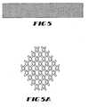
- a tubular prosthesisis formed from a solid three-dimensional braided structure, as shown in Figure 8 , having six strands forming three plies which are interbraided through the thickness of the braid.
- the prosthesisis formed from 225 denier, 30 filament cold drawn PTFE yarns, which are placed on each of the 192 bobbins on the braiding machine.
- the prosthesisAfter braiding, the prosthesis is cut to a desired length, desirably with a laser to cut and fuse the ends simultaneously.
- the prosthesisis cleaned with sodium dodecyl sulfate and then rinsed with deionized water.
- the prosthesisis placed over a mandrel and heat set to precisely set the diameter and to remove any creases or wrinkles.
- the prosthesisis attached to a stent fixation device and assembled into a catheter delivery system, or alternatively surgically implanted.
- a tubular jersey weft knitis used with a three-ply, 225 denier, 30 filament cold drawn PTFE yarns with 30 wales per 2,54 cm (1 inch) per layer and 40 courses per 2,54 cm (1 inch) per layer.
- a warp knit constructionmay also be used.
- a tubular jersey weft knit constructioninstead of a tubular jersey weft knit construction, a tubular double tri-cotton warp knit construction with similar stitched density to the tubular jersey weft knit can be used.
- the prosthesisis cut to a desired length, desirably with a laser to cut and fuse the ends simultaneously.
- the prosthesisis cleaned with sodium dodecyl sulfate and then rinsed with deionized water.
- the prosthesisis placed over a mandrel and heat set to precisely set the diameter and to remove any creases or wrinkles.
- the prosthesisis attached to a stent fixation device and assembled into a catheter delivery system, or alternatively surgically implanted.
- a one-ply, 225 denier, 30 filament cold drawn PTFE yarnis filament wound onto a mandrel of known diameter.
- the helix angle achievedis about 55 degrees.
- the mandrelis wrapped with the yarn in both directions to provide biaxial reinforcement.
- To hold the yarns in placethey are passed through a solution of solvated polyurethane elastomer, such a BIOMARK® solution, sold by Johnson & Johnson. The solvent is removed, causing the polyurethane to dry and glue the yarns together.
- the prosthesisAfter winding, the prosthesis is cut to a desired length, desirably with a laser to cut and fuse the ends simultaneously.
- the prosthesisis cleaned with sodium dodecyl sulfate and then rinsed with deionized water.
- the prosthesisis placed over a mandrel and heat set to precisely set the diameter and to remove any creases or wrinkles.
- the prosthesisis attached to a stent fixation device and assembled into a catheter delivery system, or alternatively surgically implanted.
Landscapes
- Health & Medical Sciences (AREA)
- Public Health (AREA)
- Chemical & Material Sciences (AREA)
- Veterinary Medicine (AREA)
- Life Sciences & Earth Sciences (AREA)
- Animal Behavior & Ethology (AREA)
- General Health & Medical Sciences (AREA)
- Epidemiology (AREA)
- Medicinal Chemistry (AREA)
- Vascular Medicine (AREA)
- Oral & Maxillofacial Surgery (AREA)
- Transplantation (AREA)
- Dermatology (AREA)
- Heart & Thoracic Surgery (AREA)
- Surgery (AREA)
- Chemical Kinetics & Catalysis (AREA)
- Cardiology (AREA)
- Pulmonology (AREA)
- Engineering & Computer Science (AREA)
- Biomedical Technology (AREA)
- Gastroenterology & Hepatology (AREA)
- Polymers & Plastics (AREA)
- Organic Chemistry (AREA)
- Prostheses (AREA)
- Materials For Medical Uses (AREA)
- Knitting Of Fabric (AREA)
Abstract
Description
- The present invention relates to an implantable textile prosthesis. More particularly, the present invention relates to an implantable textile prosthesis with substantially improved lubricious properties having cold drawn polytetrafluoroethylene (PTFE) yarns therein.
- Vascular grafts are commonly used as soft tissue prostheses to replace or repair damaged or diseased veins and arteries. Conventional textile implantable prostheses are manufactured using yarns made of biocompatible and biostable material. To maximize the effectiveness of prostheses, it is desirable that the prostheses have characteristics that closely resemble that of the natural body lumen. In particular, prostheses desirably exhibit long term wear and kink resistance. Typically, the yarns used in these types of textile constructions are subjected to strenuous conditions, such as constant rubbing against a stent during pulsation of blood. Such abrasive forces can result in weakening of conventional textile prosthesis made with polyethylene terephthalate (PET) yarns, which can result in loss of structural integrity, and in extreme cases graft failure. Thus, there is a need for more durable and lubricious yarns that are capable of being incorporated into vascular prostheses.
- PTFE is used in numerous demanding applications due to its excellent physical properties, which include excellent high and low temperature performance, chemical resistance and lubricious properties. PTFE is particularly useful in medical devices such as vascular prostheses. Use of PTFE yarns for textile vascular prostheses has been limited because finished PTFE yarns suitable for use in medical devices are often not commercially available to medical device manufacturers. Unfinished PTFE yarns that are available, however, typically do not possess the physical characteristics necessary for such medical device uses, such as sufficient orientation, i.e. molecular alignment of the fibers, and the requisite uniform linear density. This creates problems when processing such yarns into a textile prosthesis. For instance, unfinished yarns may accumulate in the machine during the textile prosthesis manufacturing process or stretch to create a non-uniform prosthesis. Additionally, problems may occur when such prostheses having unfinished PTFE yarns therein are placed in a body lumen because such yarns may unexpectedly and undesirably stretch. Thus, the prostheses will not perform in a consistent and predictable manner. As such, these yarns are not suitable for use in medical devices without further processing.
- Conventional means to finish PTFE yarns typically involve a heat drawing process. Heat drawing results in yarns with good orientation and uniform linear density which when incorporated into a textile vascular prosthesis exhibit predictable and consistent behavior, both in the textile manufacturing process and in vivo. However, it may be difficult to control and maintain the elevated temperature that is necessary for heat drawing and it may be expensive to obtain heat drawing equipment. Thus, conventional methods for drawing yarns suitable for use in implantable textile prostheses are less than satisfactory.
EP 0 855 170 discloses a stent graft for transluminal implantation including a resilient tubular interbraided latticework of metal or polymeric monofilaments, a tubular interbraided sleeve of polymeric multifilament yarns, and an adhesive layer between the sleeve and the latticework for bonding them together.- Accordingly, it is desirable to provide textile prostheses with improved lubricious properties comprising cold drawn PTFE yarns having have a uniform linear density and a highly oriented molecular structure and drawn using a convenient and inexpensive cold drawing process.
- The present invention relates to prostheses and methods as defined by the claims.
- The present invention provides for implantable textile prostheses having PTFE yarn, which are suitable for medical device use. More particularly, the present invention provides for textile prostheses having highly lubricious cold drawn PTFE yarns that have a highly oriented molecular structure and a uniform linear density. Cold drawn PTFE yarn exhibits enhanced handling characteristics, which minimize the tendency of yarns to fold back and accumulate during a braiding process. Yarns useful for braided grafts are desirably single or two-ply 225 denier, 30 filaments with 0,2 to 3,94 twists per cm (0.5 to 10 twists per inch) inserted.
- An implantable textile prosthesis comprising a biocompatible fabric having inner and outer surfaces and first and second ends; the fabric having a textile construction including cold drawn PTFE yarns having a substantially uniform denier and high molecular orientation. Useful textile constructions include weaves, knits, braids, filament windings, spun windings and combinations thereof.
- Another embodiment of the present invention provides a braided textile prosthesis with enhanced lubricity, biocompatibility and chemical resistance properties having a braided, tubular shaped fabric having inner and outer surfaces and first and second ends; the fabric having cold drawn PTFE yarns having a substantially uniform linear density and high molecular orientation.
- Yet another embodiment of the present invention provides for a method for making a lubricious biocompatible tubular prosthesis including providing a fabric having an inner and outer surface and first and second ends, the fabric having a plurality of polymeric filaments comprising cold drawn PTFE yarns having a substantially uniform linear density and a highly oriented molecular structure; selecting a textile construction pattern; and forming the prosthesis in accordance with a textile construction pattern.
FIG. 1 is a perspective view of a tubular woven tubular prosthesis useful in the present invention.FIG. 2 is a schematic of a conventional weave pattern useful in the present invention.FIG. 3 is a side elevational view of a braided tubular prosthesis useful in the present invention.FIG. 3A is a schematic of a diamond braid useful in the present invention.FIG. 3B is a schematic of a regular braid useful in the present invention.FIG. 3C is a schematic of a hercules braid useful in the present invention.FIG. 4 is a side elevational view of a knitted tubular prosthesis useful in the present invention.FIG. 4A is an enlarged detail ofFigure 4 .FIG. 5 is a side elevational view of a filament wound tubular prosthesis useful in the present invention.FIG. 5A is an enlarged detail ofFigure 5 .FIG. 6 shows schematically, in partial section, a prosthesis of the present invention with a series of wave-like crimps.FIG. 7 is a cross-sectional view of a portion of a multi-layered interlocked three-dimensional braided prosthesis formed in accordance with an embodiment of the present invention.FIG. 8 is a photograph of an enlarged cross-section of a solid three-dimensional braided structure formed in accordance with one embodiment of the present invention.FIG. 9 is a perspective showing of a prosthesis and a stent-graft composite of the present invention with a stent incorporated therein.FIG. 10 is a perspective showing a stent with an inner graft liner.FIG. 11 describes a cross section of an arteriovenous vascular graft.FIG. 12 is a schematic view of a cold drawing apparatus.- In accordance with the present invention, there is provided an implantable textile prosthesis and more specifically, an implantable textile prosthesis having cold drawn PTFE yarns with a substantially uniform linear density and a highly oriented molecular structure. Use of cold drawn PTFE yarns result in implantable prostheses that have excellent abrasion resistance, strength and lubricity properties. The prostheses of the present invention have characteristics that closely resemble the properties of a natural body lumen.
- Cold drawn PTFE yarns increase the durability of prostheses, which may reduce the need for physicians to routinely remove, repair and replace vascular prostheses that have been implanted. An advantage of cold drawn PTFE yarns is that they are convenient and easy to produce.
- The present invention contemplates implantable prostheses, such as endovascular grafts, balloon catheters, meshes, vascular patches, hernia plugs, stent-graft composites, blood filters and the like. One embodiment of the present invention contemplates a tubular implantable prosthesis. Examples of prostheses that may require a tubular design include intraluminal prostheses, endovascular grafts, radially deformable support components, such as radially deformable stents.
- Stent-graft composite devices are also contemplated having self-expanding stents and balloon expandable stents. Self-expanding stents include those that have a spring-like action which causes the stent to radially distend (expand and contract) or stents which expand due to the memory properties of the stent material for a particular configuration at a certain temperature. Stent-graft composite devices often pulsate in the body in accordance with the passage of blood. Such movement may cause abrasion of the graft by the metal stent, leading to a weakening of the integrity of the prosthesis. Fabrics made from cold drawn PTFE yarns perform well in conjunction with stents due to the durability and abrasion resistance of the cold drawn PTFE yarn.
- The linear density of the yarn used in the prosthesis is selected to meet specific properties desired for the prosthesis, such as porosity, flexibility and compliance. Denier is a unit of measure to represent the linear density of the yarn. In particular, denier is the weight of the yarn in grams per 9000 meters of yarn. Yarns useful in the inventive prostheses have a denier range from about 40 to about 400, depending on the specific type of vascular graft desired. Yarns desirably have a denier from about 100 to about 300. Yarns may be flat, twisted, textured or pre-shrunk. The yarns may be multifilament, monofilament or spun type. Desirably, multifilaments are used, however, where enhanced crush resistance is desired the use of monofilaments may be effective in achieving this end. Useful yarns have from about 1 to about 100 filaments and desirably about 30 filaments. A high filament count for the same overall linear density increases the yarn flexibility, reduces its stiffness and reduces permeability to viscous liquids, i.e., blood.
- Multi-ply yarns may be used in the prosthesis of the present invention. Multi-ply yarn is desirable to impart certain properties onto the drawn yam, such as higher tensile strength. The cold drawn PTFE yarns used in the present invention are desirably drawn at a temperature below the glass transition temperature (Tg) or below the maximum Tg, if the material has multiple Tg's. A suitable temperature range is from about -178°C to about +70°C. The PTFE yarn is desirably drawn at room temperature as long as room temperature is below Tg of the yarn.
- Prostheses made from cold drawn PTFE yarns can have virtually any textile construction, including weaves, knits, braids, filament windings and the like. Referring to the drawings and, in particular to
Figures 1-2 , a woven tubular prosthesis is shown. Any known weave pattern in the art, including, simple weaves, basket weaves, twill weaves, velour weaves and the like may be used. The weave pattern includeswarp yarns 2 running along the longitudinal length (L) of the woven product and fillyarns 3 running around the circumference (C) of the product the warp, the fill yarns being at approximately 90 degrees to one another with fabric flowing from the machine in the warp direction. - Braiding may also be used as shown, for example, in
Figures 3 and 3A-3C . Braiding of yarns includes the interlacing of two yarns systems such that the paths of the yarns are diagonal to the fabric delivery direction, forming either a flat or tubular structure. Useful braids include an interlocking three-dimensional braid and a solid three-dimensional braid. A multi-layered braided structure is defined as a structure formed by braiding wherein the structure has a plurality of distinct and discrete layers. These layers may be bound by interlocking yarns or by adhesive laminates, sewing or the like. - An interlocking three-dimensional braid, as shown in
Figure 7 , may be used and is defined as a braided structure having at least two layers, whereby a yarn is interbraided from a first layer into a contiguous second layer to interlock the layers of the multi-layer braid. A braiding machine capable of forming the interlocked three-dimensional braid used to form a prosthesis of the present invention is described inInternational Patent Publication No. WO 91/10766 Figure 7 , the prosthesis includes four layers, 19, 20, 21 and 22, with each layer having at least one interlocking yarn from a contiguous layer. The interlocking yarns are braided into the structure so that the yarn forms part of the first layer, as well as being part of the contiguous layer by forming the interlock. Within each layer, a segment of the braid is formed by an interlocking yarn from a contiguous layer, the layers being interbraided together. The interlocking yarns couple the multiple layers together to form a three-dimensional braid. InFigure 7 , thefirst layer 19 forms the outer layer of the interlocking three-dimensional braided structure. The outer layer is formed fromyarn 11 which is exclusively braided into the first layer along withyarn 10 which is interbraided into a second layer which is contiguous with the first layer andyarn 12 which is interbraided from the second layer up into the first layer.Second layer 20 is formed from segments of fouryarns contiguous layer 21 is formed from segments of fouryarns Layer 22 is formed in similar fashion, having threeyarns - A solid three-dimensional braided structure, as shown in
Figure 8 , may be used and is formed by continuous intertwining of the fibers. Solid three-dimensional braids are homogenous in that all yarns are present throughout the thickness of the braid. Generally, three-dimensional braiding machines used to form this type of solid braid include an array of fiber bobbins held in ring or track configurations. A suitable apparatus for forming a solid three-dimensional braid in accordance with the present invention is disclosed inU.S. Patent No. 4,719,837 . Circumferential motion of the array of the bobbins to form the braid is accomplished by shifting slotted rings containing the fiber holders. Fibers are directed through the thickness of the braid by shifting the holders between the rings. Reversal of the direction of ring and hold motions during the shift segment interlocks the fibers. Since every fiber undergoes a similar motion, all fibers become entwined in the balanced array as illustrated inFigure 8 . - Generally, a braided structure is formed having a braid angle from about 54.5° to about 90° with respect to the longitudinal axis of the braided structure, desirably about 54.5° to about 75°. The yarns of the braid tend to seek equilibrium at a braid angle of about 54.5°, which is the neutral angle for tubular vessels under pressure. Thus, when the braid angle is larger than the neutral angle, when pressure is exerted from within, for example due to fluid flow, the yarns will tend to scissor and decrease the braid angle thereby elongating or stretching the braided structure in order to reach the neutral angle.
- Additionally, knitted prostheses, as shown in
Figures 4 and 4A , may be used. Knitting involves the interlooping of one yarn system into vertical columns and horizontal rows of loops called wales and courses, respectively, with fabric coming out of the machine in the wale direction. A filament wound prosthesis, as shown inFigure 5 and 5A , may also be used where a yarn is transferred from one package to a mandrel to form a prosthesis that is wrapped with the yarn in both directions to provide a biaxial reinforcement. - Generally, tubular textile prostheses are manufactured into a single long tube and cut to a predetermined length. To cut the prosthesis, desirably a laser is used, which cuts and fuses the ends simultaneously. The prosthesis is cleaned, desirably, with sodium dodecyl sulfate and then rinsed with deionized water. The prosthesis is placed over a mandrel and heat set to precisely set the diameter and to remove any creases or wrinkles. Typically heat conditioning is carried out at a temperature range from about 125°C to about 225°C using a convection oven for a time of 20 minutes. Any known means for heating the structure may be used. The prosthesis may then be attached to a stent fixation device and assembled into a catheter delivery system, or alternatively surgically implanted.
- Once deployed, the inventive prosthesis desirably maintains its longitudinal flexibility and returns to its tubular open lumen configuration so that the lumen remains open allowing the passage of blood. As shown in
Figure 6 , crimps 4 may optionally be employed with the present invention to permit such longitudinal flexibility and structural integrity without increasing the graft thickness as measured by both fabric wall thickness and as measured between the peak-to-peak amplitude of the wave-like pattern of crimps. Theprosthesis 6 includes a generallytubular body 5 having opposing ends 7 and 9 which define therebetween an open lumen 8 which permits passage of blood once thegraft 6 is implanted in the blood vessel. - As shown in
Figure 9 and 10 , a stent may be incorporated in the prosthesis to help secure the prosthesis to the host lumen. In that way, both theprosthesis 30 and thestent 31 can be simultaneously and controllably expanded to the desired diameter or until the stent-graft composite 32 substantially conforms to the diameter of the host lumen. Any suitable means of attaching thestent 31 to theexpandable prosthesis 30, such as hooks, catches, sutures or other similar means may be used. Incorporating thestent 31 between layers of fabric orgraft walls stent 31 may include similar means capable of anchoring the prosthesis in place in the host lumen. This is often accomplished by expanding the stent-graft structure such that sufficient radial pressure against the luminal surface of the vessel provides for anchoring. Alternatively or in addition to anchoring by using a sufficiently tight radial fit, various barbs or hooks may be used to secure the prosthesis in place in the host vessel. - The prostheses of the present invention may be coated with a bio-absorbable coating, such as collagen, albumin, elastin and the like. Such coatings are known in the art and are desirable in vascular and endovascular graft applications to seal the graft and thereby prevent blood loss in the early stages of implantation. Other coatings which may be used include those disclosed in
U.S. Patent No. 5,851,229 . The'229 patent discloses a sealant composition that includes at least two polysaccharides in combination to form a hydrogel or solgel. Sealant compositions may include a bioactive agent and or be cross-linked subsequent to the application of these compositions to the substrate surface. Additionally,U.S. Patent No. 5,209,776 , discloses a composition that includes a first protein component that is preferably collagen and a second protein-supporting component that can be a proteoglycan, a saccharide or a polyalcohol. - The prosthesis of the present invention includes cold drawn PTFE yarn. Other yarns which may be incorporated therein include, but are not limited to, polyester materials such as polyethyleneterepthalate (PET), poly(glycolic acid), poly(lactic acid), polydioxanoes, polyoxalates, poly(alpha esters), polycarbonates, polyanhydrides, polyacetals, polycaprolactones, poly(orthoesters), polyamino acids, polyurethanes, polyiminocarbonates, polyamindes, poly(alkyl cyanoacrylates), sebacic acid, polyethylene glycol, polyphosphazene, bis(p-carboxyphenoxy)propane, bis(p-carboxyphenoxy)methane and copolymers and mixtures thereof, provided that these materials can be formed into a fiber suitable for use with the textile manufacturing apparatus being used. A bioabsorbable yarn may be used in either a single layer, in several different layers, or as several yarns within a textile structure to form a prosthesis having an initial porosity different from the porosity once the bioabsorbable material has been absorbed into the body.
- Axial yarns are added in some cases to limit a textile structure from stretching beyond a desired amount, and thereby significantly reducing the potential for scissoring action of the yarns. This scissoring or shearing action is detrimental to the body's healing process. The scissoring action of the strands tends to prevent the tissue and blood vessels from infiltrating the pores of the structure. Additionally, an axial yarn may be dyed and inserted into the textile structure subsequent to or during the braiding process. A dyed axial yarn positioned in the outer surface of the prosthesis aids the surgeon during implantation to indicate whether the prosthesis is straight and not twisted during the procedure.
- The prosthesis may include a radiopaque guideline or marker to provide means for viewing the implanted prosthesis fluoroscopically. The marker may extend the length of the prosthesis. Other patterns for markers may also be employed. Radiopaque markers assist the surgeon to visualize the prosthesis both during and after implantation. The marker helps show the surgeon that the prosthesis is properly positioned. Also, it will indicate whether the prosthesis has dilated or collapsed after implantation.
- The prosthesis of the present invention incorporates cold drawn PTFE yarn therein as more particularly described in commonly owned patent application, Serial No.
WO 03/091488 Figure 12 is a schematic view of the apparatus used for a method of cold drawing PTFE yarns. The apparatus ofFigure 12 includespackage creel 61,creel roller guide 63,tension roller 64,second roller 65,separator roller 66,pigtail guide 67,spindle 68, ring andtraveler 69,yarn 70 andframe 71, interrelated as shown. - As illustrated in
Figure 12 , the cold drawing apparatus desirably is equipped with apackage creel 61 which holds the undrawn yarn. The yarn is fed throughcreel roller guide 62 and then drawn overfirst roller guide 63 that spins about its axis at a first speed andsecond roller 65, which turns about its axis at a speed faster than the speed of the first roller to draw the yarn to a desired denier and to enhance filament orientation.Creel roller guide 62 is freely rotatable and the speed offirst roller guide 63 andsecond roller 65 are pre-adjustable. - The properties of the drawn yarn can be tailored to meet the requirements of a particular use. Properties of the drawn yarn may be altered, for instance, by varying the draw ratio, twisting amount and adding multiple yarns to produce a multi-ply finished yarn. The draw ratio indicates the ratio of the speed of the
second roller 65 turning about its axis compared tofirst roller 63 turning about its axis. Useful draw ratios are from about 1.05 to about 1.50. A draw ratio of higher than 1.50 may result in breakage of the yarn. The draw ratio is based on the desired tension strength, orientation and linear density of the yarn. A higher draw ratio will result in a larger reduction in the linear density of the yarn. - As shown in
Figure 12 ,yarn 70leaves pigtail guide 67 and is guided ontospindle 68 and twisted by ring andtraveler 9, which increases the strength of the yarn and prevent the filaments of the yarn from fraying. PTFE yarn that is not twisted may fray and separate due to the electrostatic forces present on the filaments of the yarn. Useful twisting rates are from about 0,2 turns per cm to about 7,87 turns per cm (about 0.5 turns per inch (tpi) to about 20 turns per inch) and more desirably from about 0,2 turns per cm to about 1,97 turns per cm (about 0.5 tpi to about 5 turns per inch). An anti-static agent may be added to the PTFE yarn to minimize static charges that may accumulate on the yarns. The cold drawn PTFE yarn desirably has a linear density of about 40 to about 300 denier. Desirably, the cold drawn PTFE yarn has a linear density from about 216-262 denier with a standard deviation from about 0.5 to about 10 denier. - The following examples are presented for purposes of illustration only and are not intended to limit the scope of the invention. For all examples, the prosthesis may be of a straight, bifurcated or otherwise designed configuration.
- A prosthesis is flat woven on an electric jacquard loom in a tubular configuration. A 1/1 plain, tubular weave is used with a warp yarn of 225 denier, 30 filament cold drawn PTFE yarn. A 225 denier, 30 filament cold drawn PTFE yarn is used with 160 warp ends per 2,54 cm (1 inch) per layer and 120 pick yarns per 2,54 cm (1 inch) per layer.
- After weaving into a tubular prosthesis, the prosthesis is cut to a desired length, desirably with a laser to cut and fuse the ends simultaneously. The prosthesis is cleaned with sodium dodecyl sulfate and then rinsed with deionized water. The prosthesis is placed over a mandrel and heat set to precisely set the diameter and to remove any creases or wrinkles.
- A graft-stent composite, in accordance with the present invention, is formed from a plain weave tubular fabric having a warp yarn of 225 denier, 30 filament cold drawn PTFE yearn and weft yarn of 225 denier, 30 filament cold drawn PTFE yarn. The ends per
square 2,54 cm (per square inch) are 188 per layer while the picks per 2,54 cm (1 inch) are 88 per layer. The fabric so formed has a wall thickness of approximately 0.12 mm or less. - After weaving into a tubular prosthesis, the prosthesis is cut to a desired length, desirably with a laser to cut and fuse the ends simultaneously. The prosthesis is cleaned with sodium dodecyl sulfate and then rinsed with deionized water. The prosthesis is placed over a mandrel and heat set to precisely set the diameter and to remove any creases or wrinkles.
- The prosthesis is optionally be crimped to impart longitudinal compliance and radial support. Crimp patterns shown in
FIG. 6 includes a series of wave-like crimps therealong. Crimps may be imparted on a finer pitch as the relatively thin fabric would not impede such fine pitch crimping. - A stent is inserted into the graft (endoprosthesis) to form a stent/graft composite. To secure the stent, it is sutured into place or inserted into a cuff of the graft. Either two stents are inserted at each end of the graft or one stent is inserted at one end. Alternatively, one stent or a series of connected stents may be inserted throughout the length of the graft. Alternatively the stent may be sandwiched between two grafts.
- A regular twill braid is used to produce a tubular prosthesis. The warp yarns and fill yarns are constructed of a 225 denier, 30 filament cold drawn PTFE yarns. A prosthesis is braided using 192 bobbins and a 55 degree helix angle.
- After braiding into a tubular prosthesis, the prosthesis is cut to a desired length, desirably with a laser to cut and fuse the ends simultaneously. The prosthesis is cleaned with sodium dodecyl sulfate and then rinsed with deionized water. The prosthesis is placed over a mandrel and heat set to precisely set the diameter and to remove any creases or wrinkles.
- A tubular prosthesis is formed from an interlocked three-dimensional, multi-layered braided structure, as shown in
Figure 7 . The prosthesis is preferably braided on a mandrel at a braid angle of 54.5 degrees. The prosthesis includes four interlocked layers made 225 denier, 30 filament cold drawn PTFE yarns having 192 bobbins (bobbins refer to the number of carriers within the braiding machine). - After braiding into a tubular prosthesis, the prosthesis is cut to a desired length, desirably with a laser to cut and fuse the ends simultaneously. The prosthesis is cleaned with sodium dodecyl sulfate and then rinsed with deionized water. The prosthesis is placed over a mandrel and heat set to precisely set the diameter and to remove any creases or wrinkles.
- A tubular prosthesis is formed from a solid three-dimensional braided structure, as shown in
Figure 8 , having six strands forming three plies which are interbraided through the thickness of the braid. The prosthesis is formed from 225 denier, 30 filament cold drawn PTFE yarns, which are placed on each of the 192 bobbins on the braiding machine. - After braiding, the prosthesis is cut to a desired length, desirably with a laser to cut and fuse the ends simultaneously. The prosthesis is cleaned with sodium dodecyl sulfate and then rinsed with deionized water. The prosthesis is placed over a mandrel and heat set to precisely set the diameter and to remove any creases or wrinkles. The prosthesis is attached to a stent fixation device and assembled into a catheter delivery system, or alternatively surgically implanted.
- A tubular jersey weft knit is used with a three-ply, 225 denier, 30 filament cold drawn PTFE yarns with 30 wales per 2,54 cm (1 inch) per layer and 40 courses per 2,54 cm (1 inch) per layer. A warp knit construction may also be used. For example, instead of a tubular jersey weft knit construction, a tubular double tri-cotton warp knit construction with similar stitched density to the tubular jersey weft knit can be used.
- After knitting, the prosthesis is cut to a desired length, desirably with a laser to cut and fuse the ends simultaneously. The prosthesis is cleaned with sodium dodecyl sulfate and then rinsed with deionized water. The prosthesis is placed over a mandrel and heat set to precisely set the diameter and to remove any creases or wrinkles. The prosthesis is attached to a stent fixation device and assembled into a catheter delivery system, or alternatively surgically implanted.
- A one-ply, 225 denier, 30 filament cold drawn PTFE yarn is filament wound onto a mandrel of known diameter. The helix angle achieved is about 55 degrees. The mandrel is wrapped with the yarn in both directions to provide biaxial reinforcement. To hold the yarns in place, they are passed through a solution of solvated polyurethane elastomer, such a BIOMARK® solution, sold by Johnson & Johnson. The solvent is removed, causing the polyurethane to dry and glue the yarns together.
- After winding, the prosthesis is cut to a desired length, desirably with a laser to cut and fuse the ends simultaneously. The prosthesis is cleaned with sodium dodecyl sulfate and then rinsed with deionized water. The prosthesis is placed over a mandrel and heat set to precisely set the diameter and to remove any creases or wrinkles. The prosthesis is attached to a stent fixation device and assembled into a catheter delivery system, or alternatively surgically implanted.
- The preferred embodiments having been thus described, it will now be evident to those skilled in the art that further variation thereto may be contemplated. Such variations are not to be regarded as a departure from the invention, the true scope of the invention being set forth in the claims appended hereto.
Claims (15)
- An implantable textile prosthesis (1, 30) comprising: a hollow tubular textile construction of a biocompatible yarn (2, 3), wherein said yarn (2, 3) comprises a drawn PTFE yarn having a substantially uniform denier and high molecular orientation fabric,
characterized in that
the PTFE yarn is cold drawn. - The prosthesis (1, 30) of claim 1, wherein said textile construction is selected from the group consisting of weaves, knits, braids, filament windings, spun windings and combinations thereof.
- The prosthesis (1, 30) of claim 1 or 2, wherein said prosthesis (1, 30) is a tubular vascular or endovascular graft.
- The prosthesis (1, 30) of any of the preceding claims,
wherein said prosthesis (1, 30) further includes a coating. - The prosthesis (1, 30) of any of the preceding claims,
wherein said prosthesis (1, 30) includes a radially deformable support component (31). - The prosthesis (1, 30) of claim 5, wherein said support component (31) is a radially deformable stents (31).
- The prosthesis (1, 30) of any of the preceding claims,
wherein said yarn (2, 3) has a linear density of at least about 40 denier; and further wherein said yarn has a linear density of no more than about 400 denier. - The prosthesis (1, 30) of any of the preceding claims,
wherein said yarn (2, 3) is twisted with at least about 0,39 twists per cm (1 twist per inch); and further wherein said yarn (2, 3) is twisted with no more than about 3,94 twists per cm (about 10 twists per inch). - The prosthesis (1, 30) of any of the preceding claims,
wherein said yarn (2, 3) includes an anti-static lubricant. - The prosthesis (1, 30) of any of the preceding claims,
wherein said yarn (2, 3) is a room temperature, cold drawn yarn (2, 3). - The prosthesis (1, 30) of any of the preceding claims,
wherein said prosthesis (1, 30) is impregnated with a leak resistant material. - The prosthesis (1, 30) of any of the preceding claims,
wherein said prosthesis (1, 30) includes an axial yarn to control longitudinal extension thereof. - The prosthesis (1, 30) according to any of the preceding claims, wherein the textile is braided and has enhanced lubricity, biocompatibility and chemical resistance properties and wherein the construction is a fabric and
wherein the fabric comprises the cold drawn PTFE yarn. - A method for making a biocompatible tubular prosthesis (1, 30) according to any of the preceding claims comprising: a) selecting a plurality of biocompatible polymeric filaments (2, 3) comprising drawn PTFE yarns having a substantially uniform linear density and a highly oriented molecular structure; b) selecting a textile construction pattern for engaging said yarns; and c) engaging said yarns in accordance with said textile construction pattern to form said tubular prosthesis (1, 30),
characterized in that
the PTFE yarn is cold drawn. - The method of claim 14, wherein said textile construction pattern is selected from the group consisting of weaves, knits, braids, filament windings, spun windings and combinations thereof.
Applications Claiming Priority (3)
| Application Number | Priority Date | Filing Date | Title |
|---|---|---|---|
| US132367 | 2002-04-25 | ||
| US10/132,367US7105021B2 (en) | 2002-04-25 | 2002-04-25 | Implantable textile prostheses having PTFE cold drawn yarns |
| PCT/US2003/009608WO2003090643A1 (en) | 2002-04-25 | 2003-03-31 | Implantable textile prostheses having ptfe cold drawn yarns |
Publications (2)
| Publication Number | Publication Date |
|---|---|
| EP1499261A1 EP1499261A1 (en) | 2005-01-26 |
| EP1499261B1true EP1499261B1 (en) | 2012-02-15 |
Family
ID=29248744
Family Applications (1)
| Application Number | Title | Priority Date | Filing Date |
|---|---|---|---|
| EP03719510AExpired - LifetimeEP1499261B1 (en) | 2002-04-25 | 2003-03-31 | Implantable textile prostheses having ptfe cold drawn yarns |
Country Status (6)
| Country | Link |
|---|---|
| US (2) | US7105021B2 (en) |
| EP (1) | EP1499261B1 (en) |
| JP (1) | JP4381827B2 (en) |
| AT (1) | ATE545386T1 (en) |
| AU (1) | AU2003223388A1 (en) |
| WO (1) | WO2003090643A1 (en) |
Families Citing this family (62)
| Publication number | Priority date | Publication date | Assignee | Title |
|---|---|---|---|---|
| US20060122691A1 (en)* | 1998-12-03 | 2006-06-08 | Jacob Richter | Hybrid stent |
| US8088060B2 (en) | 2000-03-15 | 2012-01-03 | Orbusneich Medical, Inc. | Progenitor endothelial cell capturing with a drug eluting implantable medical device |
| US9522217B2 (en) | 2000-03-15 | 2016-12-20 | Orbusneich Medical, Inc. | Medical device with coating for capturing genetically-altered cells and methods for using same |
| US7063721B2 (en)* | 2002-03-20 | 2006-06-20 | Terumo Kabushiki Kaisha | Woven tubing for stent type blood vascular prosthesis and stent type blood vascular prosthesis using the tubing |
| US7381211B2 (en)* | 2002-08-21 | 2008-06-03 | Kci Licensing, Inc. | Medical closure screen device and method |
| US8062331B2 (en) | 2002-08-21 | 2011-11-22 | Kci Licensing, Inc. | Internal and external medical closure screen systems and methods |
| US10363344B2 (en) | 2002-12-31 | 2019-07-30 | Kci Licensing, Inc. | Externally-applied patient interface system and method with a controlled region for implanted or buried bio-reactor |
| US7682381B2 (en)* | 2004-04-23 | 2010-03-23 | Boston Scientific Scimed, Inc. | Composite medical textile material and implantable devices made therefrom |
| BE1016067A3 (en)* | 2004-06-03 | 2006-02-07 | Frid Noureddine | Luminal endoprosthesis FOR OBSTRUCTION OF ANEURYSM AND METHOD OF MANUFACTURING SUCH STENT. |
| US7364587B2 (en)* | 2004-09-10 | 2008-04-29 | Scimed Life Systems, Inc. | High stretch, low dilation knit prosthetic device and method for making the same |
| US20060142852A1 (en)* | 2004-12-29 | 2006-06-29 | Boston Scientific Scimed, Inc. | Low profile, durable, reinforced ePTFE composite graft |
| WO2006099020A2 (en)* | 2005-03-09 | 2006-09-21 | The University Of Tennessee Research Foundation | Barrier stent and use thereof |
| WO2007053592A2 (en)* | 2005-10-31 | 2007-05-10 | Cook Incorporated | Composite stent graft |
| US20070203564A1 (en)* | 2006-02-28 | 2007-08-30 | Boston Scientific Scimed, Inc. | Biodegradable implants having accelerated biodegradation properties in vivo |
| CN101404960B (en)* | 2006-03-31 | 2012-06-06 | 日本瑞翁株式会社 | Stent delivery catheter |
| US7594928B2 (en)* | 2006-05-17 | 2009-09-29 | Boston Scientific Scimed, Inc. | Bioabsorbable stents with reinforced filaments |
| US7614258B2 (en) | 2006-10-19 | 2009-11-10 | C.R. Bard, Inc. | Prosthetic repair fabric |
| US9622888B2 (en) | 2006-11-16 | 2017-04-18 | W. L. Gore & Associates, Inc. | Stent having flexibly connected adjacent stent elements |
| DE102006062384A1 (en)* | 2006-12-22 | 2008-06-26 | Aesculap Ag & Co. Kg | Tubular vascular prosthesis for replacement of the ascending aorta |
| DE102006062360A1 (en)* | 2006-12-22 | 2008-06-26 | Aesculap Ag & Co. Kg | Woven artificial organ for an aortic sinus has a first cylindrical section away from a heart, a second cylindrical section with a wider diameter to form a bulbus and a third cylindrical section near to a heart |
| US8177834B2 (en)* | 2007-03-12 | 2012-05-15 | Cook Medical Technologies Llc | Woven fabric with shape memory element strands |
| DE102007032156A1 (en)* | 2007-07-03 | 2008-10-23 | Aesculap Ag | Textile vascular prosthesis |
| US8597342B2 (en)* | 2007-08-24 | 2013-12-03 | Cook Medical Technologies Llc | Textile graft for in situ fenestration |
| CA2701576C (en)* | 2007-10-17 | 2016-06-21 | Angiomed Gmbh & Co. Medizintechnik Kg | Delivery system for a self-expanding device for placement in a bodily lumen |
| US8834552B2 (en)* | 2007-12-27 | 2014-09-16 | Cook Medical Technologies Llc | Stent graft having floating yarns |
| US8926688B2 (en) | 2008-01-11 | 2015-01-06 | W. L. Gore & Assoc. Inc. | Stent having adjacent elements connected by flexible webs |
| CA3010828A1 (en) | 2008-01-17 | 2009-07-23 | Boston Scientific Scimed, Inc. | Stent with anti-migration feature |
| US9427494B2 (en) | 2008-01-21 | 2016-08-30 | International Life Sciences, Llc | Fibre-based surgical implant and method of manufacture |
| US8701716B2 (en)* | 2008-02-29 | 2014-04-22 | Federal-Mogul Corporation | Protective textile sleeve having high edge abrasion resistance and method of construction |
| US20100010339A1 (en)* | 2008-03-13 | 2010-01-14 | Smith Christopher K | Method and device for easy access to subintimally implanted vascular access ports |
| US20090234267A1 (en)* | 2008-03-13 | 2009-09-17 | Ross John R | Method and device for easy access to vascular graft cannulation sites |
| CA2720466A1 (en)* | 2008-05-09 | 2009-11-12 | Juergen Dorn | Method of loading a stent into a sheath |
| GB0815339D0 (en)* | 2008-08-21 | 2008-10-01 | Angiomed Ag | Method of loading a stent into a sheath |
| US8353943B2 (en)* | 2008-08-29 | 2013-01-15 | Cook Medical Technologies Llc | Variable weave graft with metal strand reinforcement for in situ fenestration |
| CA2740008C (en)* | 2008-10-09 | 2017-01-31 | Mimedx, Inc. | Methods of making biocomposite medical constructs and related constructs including artificial tissues, vessels and patches |
| GB0823716D0 (en)* | 2008-12-31 | 2009-02-04 | Angiomed Ag | Stent delivery device with rolling stent retaining sheath |
| GB0921238D0 (en) | 2009-12-03 | 2010-01-20 | Angiomed Ag | Stent device delivery system and method of making such |
| GB0921237D0 (en)* | 2009-12-03 | 2010-01-20 | Angiomed Ag | Stent device delivery system and method of making such |
| GB0921236D0 (en)* | 2009-12-03 | 2010-01-20 | Angiomed Ag | Stent device delivery system and method of making such |
| GB0921240D0 (en) | 2009-12-03 | 2010-01-20 | Angiomed Ag | Stent device delivery system and method of making such |
| US9408956B2 (en) | 2010-09-24 | 2016-08-09 | Kci Licensing, Inc. | Cellular control and tissue regeneration systems and methods |
| KR101213851B1 (en) | 2010-11-24 | 2012-12-18 | 주식회사 효성 | Tubular braid and Composite Hollow Fiber Membrane using the same |
| GB201020373D0 (en) | 2010-12-01 | 2011-01-12 | Angiomed Ag | Device to release a self-expanding implant |
| BR112014005395A2 (en)* | 2011-09-09 | 2017-03-28 | Endoluminal Sciences Pty Ltd | biocompatible hydrogel or foam, endoluminal sealing and method for sealing a lumen |
| EP2916786B1 (en) | 2012-11-12 | 2018-03-21 | KCI Licensing, Inc. | Externally-applied wound dressings and closures |
| EP2968871B8 (en) | 2013-03-15 | 2017-08-23 | KCI Licensing, Inc. | Topical vacuum-press surgical incisional dressings |
| US10492956B2 (en) | 2013-03-15 | 2019-12-03 | Kci Licensing, Inc. | Topical vacuum-press surgical incisional dressings, surgical adjuncts, hybrids and composites |
| CN104720941A (en)* | 2013-12-20 | 2015-06-24 | 微创神通医疗科技(上海)有限公司 | Vessel stent and production method thereof |
| KR101626892B1 (en)* | 2014-04-25 | 2016-06-03 | 주식회사서륭 | Manufacturing method of teflon fablic for artficial blood stent |
| US10299948B2 (en) | 2014-11-26 | 2019-05-28 | W. L. Gore & Associates, Inc. | Balloon expandable endoprosthesis |
| JP6177259B2 (en)* | 2015-01-13 | 2017-08-09 | 日本ライフライン株式会社 | Stents and stent grafts |
| USD801400S1 (en)* | 2015-03-20 | 2017-10-31 | Tek Group International | Creel roller guide |
| EP3349687B1 (en)* | 2015-09-15 | 2020-09-09 | THE UNITED STATES OF AMERICA, represented by the S | Devices for effectuating percutaneous glenn and fontan procedures |
| US10568752B2 (en) | 2016-05-25 | 2020-02-25 | W. L. Gore & Associates, Inc. | Controlled endoprosthesis balloon expansion |
| CN106400295B (en)* | 2016-08-31 | 2018-06-19 | 河南科技大学 | Three-dimensional woven tube and the three dimensional knitting machine and weaving for making the three-dimensional woven tube |
| KR101927707B1 (en) | 2017-04-26 | 2018-12-11 | 원광대학교산학협력단 | Scaffold fabrication method using sheet manufactured with porous filament |
| WO2019122150A1 (en)* | 2017-12-21 | 2019-06-27 | Aran Biomedical Teoranta | Medical balloon |
| WO2019149680A1 (en) | 2018-01-31 | 2019-08-08 | Teijin Aramid B.V. | Catheter tubular shaft |
| WO2019173472A1 (en)* | 2018-03-06 | 2019-09-12 | Avery Dennison Retail Information Services, Llc | Label and related method |
| CN111801754B (en)* | 2018-03-06 | 2022-04-12 | 京瓷Avx元器件公司 | Multilayer Ceramic Capacitors with Ultra-Broadband Performance |
| EP3908233B1 (en)* | 2019-01-07 | 2024-08-21 | Boston Scientific Scimed, Inc. | Stent with anti-migration feature |
| WO2025106611A1 (en)* | 2023-11-17 | 2025-05-22 | Atex Technologies, Inc. | Predictable textile structures for implantation |
Family Cites Families (52)
| Publication number | Priority date | Publication date | Assignee | Title |
|---|---|---|---|---|
| US608614A (en)* | 1898-08-09 | Carl marschner | ||
| CA937720A (en) | 1966-08-31 | 1973-12-04 | Shell Internationale Research Maatschappij, N.V. | Method for the production of crimped fibres from thermoplastic macromolecular materials |
| US3966867A (en)* | 1968-08-31 | 1976-06-29 | Akzona Incorporated | Manufacture of unique polyethylene terephthalate fiber |
| US4003974A (en)* | 1975-04-04 | 1977-01-18 | E. I. Du Pont De Nemours And Company | Continuous spin-drawing process for preparing polyethylene terephthalate yarns |
| US4064214A (en)* | 1975-09-22 | 1977-12-20 | E. I. Du Pont De Nemours And Company | Process for making polytetrafluoroethylene yarn |
| US4414169A (en)* | 1979-02-26 | 1983-11-08 | Fiber Industries, Inc. | Production of polyester filaments of high strength possessing an unusually stable internal structure employing improved processing conditions |
| JPS57154410A (en)* | 1981-03-13 | 1982-09-24 | Toray Ind Inc | Polyethylene terephthalate fiber and its production |
| US4482516A (en) | 1982-09-10 | 1984-11-13 | W. L. Gore & Associates, Inc. | Process for producing a high strength porous polytetrafluoroethylene product having a coarse microstructure |
| US4897902A (en)* | 1982-09-30 | 1990-02-06 | Allied-Signal Inc. | Fabrics and twisted yarns formed from ultrahigh tenacity and modulus fibers, and methods of heat-setting |
| US4485516A (en)* | 1982-10-28 | 1984-12-04 | Crook Philip A | Lawn mower scraper |
| US4822366A (en)* | 1986-10-16 | 1989-04-18 | Boehringer Mannheim Corporation | Modular knee prosthesis |
| DE3770623D1 (en)* | 1987-03-17 | 1991-07-11 | Unitika Ltd | POLYESTER FIBER AND METHOD FOR PRODUCING THE SAME. |
| DE3878899T2 (en)* | 1987-07-30 | 1993-07-22 | Toray Industries | POROESE POLYTETRAFLUORAETHYLENE MEMBRANE, SEPARATING DEVICE USING THIS MEMBRANE AND METHOD FOR THE PRODUCTION THEREOF. |
| US4965342A (en)* | 1988-06-03 | 1990-10-23 | Arizona Board Of Regents, Acting On Behalf Of Arizona State University | High molecular weight polymers and copolymers of 3-hydroxyoxetane and derivatives thereof |
| JPH0291210A (en) | 1988-09-29 | 1990-03-30 | Toray Ind Inc | Extra fine thermoplastic fluoro fiber and production thereof |
| CA2006152C (en)* | 1988-12-27 | 1999-03-23 | John Edward Slamin | Modular knee prosthesis |
| US4936853A (en)* | 1989-01-11 | 1990-06-26 | Kirschner Medical Corporation | Modular knee prosthesis |
| US5098625A (en)* | 1989-03-14 | 1992-03-24 | Yeu Ming Tai Chemical Industrial Co., Ltd. | Process for forming an expanded porous tetrafluoroethylene polymer |
| US4985037A (en)* | 1989-05-22 | 1991-01-15 | Petersen Thomas D | Universal modular prosthesis stem extension |
| CA2039849A1 (en)* | 1990-05-11 | 1991-11-12 | F. Holmes Simons | Apparatus for spinning synthetic melt spinnable polymers |
| US5238740A (en)* | 1990-05-11 | 1993-08-24 | Hoechst Celanese Corporation | Drawn polyester yarn having a high tenacity and high modulus and a low shrinkage |
| USRE35972E (en) | 1990-05-18 | 1998-11-24 | North Carolina State University | Ultra-oriented crystalline filaments |
| JP2840143B2 (en)* | 1991-09-04 | 1998-12-24 | 篤識 北村 | Manufacturing method for seamless tube products |
| DE4220915A1 (en)* | 1992-06-25 | 1994-01-05 | Zimmer Ag | Cooling filaments in high speed melt spinning - with cooling air supplied by entrainment in perforated first section of cooling chimney |
| US5944756A (en)* | 1994-02-22 | 1999-08-31 | Johnson & Johnson Professional, Inc. | Modular prosthesis with offset attachment mechanism |
| JP3077534B2 (en)* | 1994-05-31 | 2000-08-14 | 日立電線株式会社 | High strength fiber of polytetrafluoroethylene and method for producing the same |
| WO1996013233A1 (en)* | 1994-10-28 | 1996-05-09 | Intermedics Orthopedics, Inc. | Knee prosthesis with shims |
| US5741332A (en)* | 1995-01-23 | 1998-04-21 | Meadox Medicals, Inc. | Three-dimensional braided soft tissue prosthesis |
| US5609642A (en)* | 1995-02-15 | 1997-03-11 | Smith & Nephew Richards Inc. | Tibial trial prosthesis and bone preparation system |
| US5758562A (en)* | 1995-10-11 | 1998-06-02 | Schneider (Usa) Inc. | Process for manufacturing braided composite prosthesis |
| US5607478A (en)* | 1996-03-14 | 1997-03-04 | Meadox Medicals Inc. | Yarn wrapped PTFE tubular prosthesis |
| US5718159A (en)* | 1996-04-30 | 1998-02-17 | Schneider (Usa) Inc. | Process for manufacturing three-dimensional braided covered stent |
| US5891191A (en)* | 1996-04-30 | 1999-04-06 | Schneider (Usa) Inc | Cobalt-chromium-molybdenum alloy stent and stent-graft |
| US5670161A (en)* | 1996-05-28 | 1997-09-23 | Healy; Kevin E. | Biodegradable stent |
| EP0845965A1 (en)* | 1996-06-18 | 1998-06-10 | Mehran Kasra | Bone prosthesis fixation device and methods of using same |
| US5928279A (en) | 1996-07-03 | 1999-07-27 | Baxter International Inc. | Stented, radially expandable, tubular PTFE grafts |
| US5782921A (en)* | 1996-07-23 | 1998-07-21 | Johnson & Johnson Professional, Inc. | Modular knee prosthesis |
| DK0855954T3 (en)* | 1996-10-21 | 2000-05-22 | Gefinex Jackon Gmbh | Plastic Text Glazing |
| US5957974A (en) | 1997-01-23 | 1999-09-28 | Schneider (Usa) Inc | Stent graft with braided polymeric sleeve |
| DE19722869C2 (en)* | 1997-05-31 | 1999-04-15 | Heiner Rogmann | Method of fertilizing a lawn |
| US5976147A (en)* | 1997-07-11 | 1999-11-02 | Johnson & Johnson Professional, Inc | Modular instrumentation for bone preparation and implant trial reduction of orthopedic implants |
| US5976188A (en)* | 1997-10-21 | 1999-11-02 | Johnson & Johnson Professional, Inc. | Modular prosthesis system with hybrid fixation |
| EP0913132B1 (en)* | 1997-10-28 | 2004-02-11 | Centerpulse Orthopedics Ltd. | Knee prosthesis |
| US6074424A (en)* | 1998-01-23 | 2000-06-13 | Sulzer Orthopedics Inc. | Implantable knee joint prosthesis convertible from primary to revision |
| US5989709A (en) | 1998-04-30 | 1999-11-23 | Gore Enterprises Holdings, Inc. | Polytetrafluoroethylene fiber |
| US6068805A (en)* | 1999-01-11 | 2000-05-30 | 3M Innovative Properties Company | Method for making a fiber containing a fluorochemical polymer melt additive and having a low melting, high solids spin finish |
| US6214052B1 (en)* | 1999-01-19 | 2001-04-10 | Sulzer Orthopedics Inc. | Tibial component with a reversible, adjustable stem |
| AU771796B2 (en)* | 1999-02-03 | 2004-04-01 | Depuy Orthopaedics, Inc. | Modular joint prosthesis system |
| US6165223A (en)* | 1999-03-01 | 2000-12-26 | Biomet, Inc. | Floating bearing knee joint prosthesis with a fixed tibial post |
| GB2347861B (en) | 1999-03-13 | 2003-11-26 | Biointeractions Ltd | Biocompatible endoprostheses |
| US6379388B1 (en)* | 1999-12-08 | 2002-04-30 | Ortho Development Corporation | Tibial prosthesis locking system and method of repairing knee joint |
| US6485519B2 (en)* | 2001-01-29 | 2002-11-26 | Bristol-Myers Squibb Company | Constrained prosthetic knee with rotating bearing |
- 2002
- 2002-04-25USUS10/132,367patent/US7105021B2/ennot_activeExpired - Fee Related
- 2003
- 2003-03-31WOPCT/US2003/009608patent/WO2003090643A1/enactiveApplication Filing
- 2003-03-31JPJP2003587284Apatent/JP4381827B2/ennot_activeExpired - Fee Related
- 2003-03-31AUAU2003223388Apatent/AU2003223388A1/ennot_activeAbandoned
- 2003-03-31ATAT03719510Tpatent/ATE545386T1/enactive
- 2003-03-31EPEP03719510Apatent/EP1499261B1/ennot_activeExpired - Lifetime
- 2006
- 2006-08-04USUS11/499,475patent/US8197537B2/ennot_activeExpired - Fee Related
Also Published As
| Publication number | Publication date |
|---|---|
| WO2003090643A1 (en) | 2003-11-06 |
| US7105021B2 (en) | 2006-09-12 |
| ATE545386T1 (en) | 2012-03-15 |
| US8197537B2 (en) | 2012-06-12 |
| JP4381827B2 (en) | 2009-12-09 |
| US20030204235A1 (en) | 2003-10-30 |
| AU2003223388A1 (en) | 2003-11-10 |
| EP1499261A1 (en) | 2005-01-26 |
| US20060271157A1 (en) | 2006-11-30 |
| JP2005523107A (en) | 2005-08-04 |
Similar Documents
| Publication | Publication Date | Title |
|---|---|---|
| EP1499261B1 (en) | Implantable textile prostheses having ptfe cold drawn yarns | |
| EP1763600B1 (en) | Metallic fibers reinforced textile prosthesis | |
| EP2136858B1 (en) | Woven fabric with shape memory element strands | |
| AU676494B2 (en) | Three-dimensional braided soft tissue prosthesis | |
| EP0804909B1 (en) | Process for making a three dimensional braided prosthesis | |
| US5741332A (en) | Three-dimensional braided soft tissue prosthesis | |
| US6592617B2 (en) | Three-dimensional braided covered stent | |
| US7083644B1 (en) | Implantable prostheses with improved mechanical and chemical properties | |
| WO2005115272A2 (en) | Composite medical textile material and implantable devices made therefrom |
Legal Events
| Date | Code | Title | Description |
|---|---|---|---|
| PUAI | Public reference made under article 153(3) epc to a published international application that has entered the european phase | Free format text:ORIGINAL CODE: 0009012 | |
| 17P | Request for examination filed | Effective date:20041119 | |
| AK | Designated contracting states | Kind code of ref document:A1 Designated state(s):AT BE BG CH CY CZ DE DK EE ES FI FR GB GR HU IE IT LI LU MC NL PT RO SE SI SK TR | |
| AX | Request for extension of the european patent | Extension state:AL LT LV MK | |
| 17Q | First examination report despatched | Effective date:20080714 | |
| GRAP | Despatch of communication of intention to grant a patent | Free format text:ORIGINAL CODE: EPIDOSNIGR1 | |
| GRAS | Grant fee paid | Free format text:ORIGINAL CODE: EPIDOSNIGR3 | |
| GRAA | (expected) grant | Free format text:ORIGINAL CODE: 0009210 | |
| AK | Designated contracting states | Kind code of ref document:B1 Designated state(s):AT BE BG CH CY CZ DE DK EE ES FI FR GB GR HU IE IT LI LU MC NL PT RO SE SI SK TR | |
| REG | Reference to a national code | Ref country code:CH Ref legal event code:EP Ref country code:GB Ref legal event code:FG4D | |
| REG | Reference to a national code | Ref country code:IE Ref legal event code:FG4D | |
| REG | Reference to a national code | Ref country code:AT Ref legal event code:REF Ref document number:545386 Country of ref document:AT Kind code of ref document:T Effective date:20120315 | |
| REG | Reference to a national code | Ref country code:DE Ref legal event code:R096 Ref document number:60340011 Country of ref document:DE Effective date:20120412 | |
| REG | Reference to a national code | Ref country code:NL Ref legal event code:T3 | |
| PG25 | Lapsed in a contracting state [announced via postgrant information from national office to epo] | Ref country code:BE Free format text:LAPSE BECAUSE OF FAILURE TO SUBMIT A TRANSLATION OF THE DESCRIPTION OR TO PAY THE FEE WITHIN THE PRESCRIBED TIME-LIMIT Effective date:20120215 Ref country code:GR Free format text:LAPSE BECAUSE OF FAILURE TO SUBMIT A TRANSLATION OF THE DESCRIPTION OR TO PAY THE FEE WITHIN THE PRESCRIBED TIME-LIMIT Effective date:20120516 Ref country code:PT Free format text:LAPSE BECAUSE OF FAILURE TO SUBMIT A TRANSLATION OF THE DESCRIPTION OR TO PAY THE FEE WITHIN THE PRESCRIBED TIME-LIMIT Effective date:20120615 Ref country code:FI Free format text:LAPSE BECAUSE OF FAILURE TO SUBMIT A TRANSLATION OF THE DESCRIPTION OR TO PAY THE FEE WITHIN THE PRESCRIBED TIME-LIMIT Effective date:20120215 | |
| REG | Reference to a national code | Ref country code:AT Ref legal event code:MK05 Ref document number:545386 Country of ref document:AT Kind code of ref document:T Effective date:20120215 | |
| PG25 | Lapsed in a contracting state [announced via postgrant information from national office to epo] | Ref country code:CY Free format text:LAPSE BECAUSE OF FAILURE TO SUBMIT A TRANSLATION OF THE DESCRIPTION OR TO PAY THE FEE WITHIN THE PRESCRIBED TIME-LIMIT Effective date:20120215 | |
| PG25 | Lapsed in a contracting state [announced via postgrant information from national office to epo] | Ref country code:SI Free format text:LAPSE BECAUSE OF FAILURE TO SUBMIT A TRANSLATION OF THE DESCRIPTION OR TO PAY THE FEE WITHIN THE PRESCRIBED TIME-LIMIT Effective date:20120215 Ref country code:RO Free format text:LAPSE BECAUSE OF FAILURE TO SUBMIT A TRANSLATION OF THE DESCRIPTION OR TO PAY THE FEE WITHIN THE PRESCRIBED TIME-LIMIT Effective date:20120215 Ref country code:MC Free format text:LAPSE BECAUSE OF NON-PAYMENT OF DUE FEES Effective date:20120331 Ref country code:DK Free format text:LAPSE BECAUSE OF FAILURE TO SUBMIT A TRANSLATION OF THE DESCRIPTION OR TO PAY THE FEE WITHIN THE PRESCRIBED TIME-LIMIT Effective date:20120215 Ref country code:SE Free format text:LAPSE BECAUSE OF FAILURE TO SUBMIT A TRANSLATION OF THE DESCRIPTION OR TO PAY THE FEE WITHIN THE PRESCRIBED TIME-LIMIT Effective date:20120215 Ref country code:EE Free format text:LAPSE BECAUSE OF FAILURE TO SUBMIT A TRANSLATION OF THE DESCRIPTION OR TO PAY THE FEE WITHIN THE PRESCRIBED TIME-LIMIT Effective date:20120215 Ref country code:CZ Free format text:LAPSE BECAUSE OF FAILURE TO SUBMIT A TRANSLATION OF THE DESCRIPTION OR TO PAY THE FEE WITHIN THE PRESCRIBED TIME-LIMIT Effective date:20120215 | |
| REG | Reference to a national code | Ref country code:CH Ref legal event code:PL | |
| PG25 | Lapsed in a contracting state [announced via postgrant information from national office to epo] | Ref country code:SK Free format text:LAPSE BECAUSE OF FAILURE TO SUBMIT A TRANSLATION OF THE DESCRIPTION OR TO PAY THE FEE WITHIN THE PRESCRIBED TIME-LIMIT Effective date:20120215 Ref country code:IT Free format text:LAPSE BECAUSE OF FAILURE TO SUBMIT A TRANSLATION OF THE DESCRIPTION OR TO PAY THE FEE WITHIN THE PRESCRIBED TIME-LIMIT Effective date:20120215 | |
| PLBE | No opposition filed within time limit | Free format text:ORIGINAL CODE: 0009261 | |
| REG | Reference to a national code | Ref country code:FR Ref legal event code:ST Effective date:20121130 | |
| STAA | Information on the status of an ep patent application or granted ep patent | Free format text:STATUS: NO OPPOSITION FILED WITHIN TIME LIMIT | |
| 26N | No opposition filed | Effective date:20121116 | |
| GBPC | Gb: european patent ceased through non-payment of renewal fee | Effective date:20120515 | |
| PG25 | Lapsed in a contracting state [announced via postgrant information from national office to epo] | Ref country code:AT Free format text:LAPSE BECAUSE OF FAILURE TO SUBMIT A TRANSLATION OF THE DESCRIPTION OR TO PAY THE FEE WITHIN THE PRESCRIBED TIME-LIMIT Effective date:20120215 Ref country code:FR Free format text:LAPSE BECAUSE OF NON-PAYMENT OF DUE FEES Effective date:20120416 Ref country code:CH Free format text:LAPSE BECAUSE OF NON-PAYMENT OF DUE FEES Effective date:20120331 Ref country code:LI Free format text:LAPSE BECAUSE OF NON-PAYMENT OF DUE FEES Effective date:20120331 | |
| REG | Reference to a national code | Ref country code:DE Ref legal event code:R097 Ref document number:60340011 Country of ref document:DE Effective date:20121116 | |
| PG25 | Lapsed in a contracting state [announced via postgrant information from national office to epo] | Ref country code:ES Free format text:LAPSE BECAUSE OF FAILURE TO SUBMIT A TRANSLATION OF THE DESCRIPTION OR TO PAY THE FEE WITHIN THE PRESCRIBED TIME-LIMIT Effective date:20120526 Ref country code:GB Free format text:LAPSE BECAUSE OF NON-PAYMENT OF DUE FEES Effective date:20120515 | |
| PGFP | Annual fee paid to national office [announced via postgrant information from national office to epo] | Ref country code:IE Payment date:20130312 Year of fee payment:11 Ref country code:DE Payment date:20130327 Year of fee payment:11 | |
| PGFP | Annual fee paid to national office [announced via postgrant information from national office to epo] | Ref country code:NL Payment date:20130309 Year of fee payment:11 | |
| PG25 | Lapsed in a contracting state [announced via postgrant information from national office to epo] | Ref country code:BG Free format text:LAPSE BECAUSE OF FAILURE TO SUBMIT A TRANSLATION OF THE DESCRIPTION OR TO PAY THE FEE WITHIN THE PRESCRIBED TIME-LIMIT Effective date:20120515 | |
| PG25 | Lapsed in a contracting state [announced via postgrant information from national office to epo] | Ref country code:TR Free format text:LAPSE BECAUSE OF FAILURE TO SUBMIT A TRANSLATION OF THE DESCRIPTION OR TO PAY THE FEE WITHIN THE PRESCRIBED TIME-LIMIT Effective date:20120215 | |
| PG25 | Lapsed in a contracting state [announced via postgrant information from national office to epo] | Ref country code:LU Free format text:LAPSE BECAUSE OF NON-PAYMENT OF DUE FEES Effective date:20120331 | |
| PG25 | Lapsed in a contracting state [announced via postgrant information from national office to epo] | Ref country code:HU Free format text:LAPSE BECAUSE OF FAILURE TO SUBMIT A TRANSLATION OF THE DESCRIPTION OR TO PAY THE FEE WITHIN THE PRESCRIBED TIME-LIMIT Effective date:20030331 | |
| REG | Reference to a national code | Ref country code:DE Ref legal event code:R119 Ref document number:60340011 Country of ref document:DE | |
| REG | Reference to a national code | Ref country code:NL Ref legal event code:V1 Effective date:20141001 | |
| REG | Reference to a national code | Ref country code:IE Ref legal event code:MM4A Ref country code:DE Ref legal event code:R119 Ref document number:60340011 Country of ref document:DE Effective date:20141001 | |
| PG25 | Lapsed in a contracting state [announced via postgrant information from national office to epo] | Ref country code:IE Free format text:LAPSE BECAUSE OF NON-PAYMENT OF DUE FEES Effective date:20140331 Ref country code:DE Free format text:LAPSE BECAUSE OF NON-PAYMENT OF DUE FEES Effective date:20141001 | |
| PG25 | Lapsed in a contracting state [announced via postgrant information from national office to epo] | Ref country code:NL Free format text:LAPSE BECAUSE OF NON-PAYMENT OF DUE FEES Effective date:20141001 |