EP1496954B1 - Method for spray-coating a tubular medical device - Google Patents
Method for spray-coating a tubular medical deviceDownload PDFInfo
- Publication number
- EP1496954B1 EP1496954B1EP03718045AEP03718045AEP1496954B1EP 1496954 B1EP1496954 B1EP 1496954B1EP 03718045 AEP03718045 AEP 03718045AEP 03718045 AEP03718045 AEP 03718045AEP 1496954 B1EP1496954 B1EP 1496954B1
- Authority
- EP
- European Patent Office
- Prior art keywords
- core wire
- coating formulation
- tubular wall
- stent
- coating
- Prior art date
- Legal status (The legal status is an assumption and is not a legal conclusion. Google has not performed a legal analysis and makes no representation as to the accuracy of the status listed.)
- Expired - Lifetime
Links
Images


Classifications
- B—PERFORMING OPERATIONS; TRANSPORTING
- B05—SPRAYING OR ATOMISING IN GENERAL; APPLYING FLUENT MATERIALS TO SURFACES, IN GENERAL
- B05B—SPRAYING APPARATUS; ATOMISING APPARATUS; NOZZLES
- B05B5/00—Electrostatic spraying apparatus; Spraying apparatus with means for charging the spray electrically; Apparatus for spraying liquids or other fluent materials by other electric means
- B05B5/08—Plant for applying liquids or other fluent materials to objects
- B05B5/087—Arrangements of electrodes, e.g. of charging, shielding, collecting electrodes
- A—HUMAN NECESSITIES
- A61—MEDICAL OR VETERINARY SCIENCE; HYGIENE
- A61L—METHODS OR APPARATUS FOR STERILISING MATERIALS OR OBJECTS IN GENERAL; DISINFECTION, STERILISATION OR DEODORISATION OF AIR; CHEMICAL ASPECTS OF BANDAGES, DRESSINGS, ABSORBENT PADS OR SURGICAL ARTICLES; MATERIALS FOR BANDAGES, DRESSINGS, ABSORBENT PADS OR SURGICAL ARTICLES
- A61L27/00—Materials for grafts or prostheses or for coating grafts or prostheses
- A61L27/28—Materials for coating prostheses
- A61L27/34—Macromolecular materials
- A—HUMAN NECESSITIES
- A61—MEDICAL OR VETERINARY SCIENCE; HYGIENE
- A61L—METHODS OR APPARATUS FOR STERILISING MATERIALS OR OBJECTS IN GENERAL; DISINFECTION, STERILISATION OR DEODORISATION OF AIR; CHEMICAL ASPECTS OF BANDAGES, DRESSINGS, ABSORBENT PADS OR SURGICAL ARTICLES; MATERIALS FOR BANDAGES, DRESSINGS, ABSORBENT PADS OR SURGICAL ARTICLES
- A61L29/00—Materials for catheters, medical tubing, cannulae, or endoscopes or for coating catheters
- A61L29/08—Materials for coatings
- A61L29/085—Macromolecular materials
- A—HUMAN NECESSITIES
- A61—MEDICAL OR VETERINARY SCIENCE; HYGIENE
- A61L—METHODS OR APPARATUS FOR STERILISING MATERIALS OR OBJECTS IN GENERAL; DISINFECTION, STERILISATION OR DEODORISATION OF AIR; CHEMICAL ASPECTS OF BANDAGES, DRESSINGS, ABSORBENT PADS OR SURGICAL ARTICLES; MATERIALS FOR BANDAGES, DRESSINGS, ABSORBENT PADS OR SURGICAL ARTICLES
- A61L31/00—Materials for other surgical articles, e.g. stents, stent-grafts, shunts, surgical drapes, guide wires, materials for adhesion prevention, occluding devices, surgical gloves, tissue fixation devices
- A61L31/08—Materials for coatings
- A61L31/10—Macromolecular materials
- B—PERFORMING OPERATIONS; TRANSPORTING
- B05—SPRAYING OR ATOMISING IN GENERAL; APPLYING FLUENT MATERIALS TO SURFACES, IN GENERAL
- B05B—SPRAYING APPARATUS; ATOMISING APPARATUS; NOZZLES
- B05B5/00—Electrostatic spraying apparatus; Spraying apparatus with means for charging the spray electrically; Apparatus for spraying liquids or other fluent materials by other electric means
- B05B5/08—Plant for applying liquids or other fluent materials to objects
- B05B5/12—Plant for applying liquids or other fluent materials to objects specially adapted for coating the interior of hollow bodies
- B—PERFORMING OPERATIONS; TRANSPORTING
- B05—SPRAYING OR ATOMISING IN GENERAL; APPLYING FLUENT MATERIALS TO SURFACES, IN GENERAL
- B05D—PROCESSES FOR APPLYING FLUENT MATERIALS TO SURFACES, IN GENERAL
- B05D1/00—Processes for applying liquids or other fluent materials
- B05D1/02—Processes for applying liquids or other fluent materials performed by spraying
- B05D1/04—Processes for applying liquids or other fluent materials performed by spraying involving the use of an electrostatic field
- B05D1/045—Processes for applying liquids or other fluent materials performed by spraying involving the use of an electrostatic field on non-conductive substrates
Definitions
- the inventionrelates generally to a method for coating a stent or a medical device having a tubular wall. More particularly, the invention is directed to a method for electrostatic spray-coating a stent or a medical device having a tubular wall, according to the preamble of claim 1 or 22. A method comprising these steps is known from DE 202002234.
- Implantable stentshave been coated with a coating comprising a biocompatible polymer to reduce adverse physiological reactions, such as restenosis, caused by uncoated surfaces of medical devices inserted or implanted in patient's body.
- the coatingcan incorporate a biologically active material.
- implanted stentshave been used to carry medicinal agents, such as thrombolytic agents. See, U.S. Patent No. 6,099,562 to Ding et al., U.S. Patent No. 5,879,697 to Ding et al., Pinchuk to U.S. Patent No. 5,092,877, U.S. Patent No. 5,304,121 to Sahatjian.
- Such coatingshave been applied to the surface of a medical device by various methods, e.g., spray coating and dip coating.
- a tubular wallsuch as a stent, having openings therein
- ithas been extremely difficult to coat only the inner surface of a tubular wall without coating the outer surface and vice versa.
- the ratio of coating thickness placed on the inner surface of the tubular wall and placed on the outer surface of the tubular wall created by a conventional methodis fixed and cannot be varied.
- the ratio of coating thicknessdepends on the configuration of the tubular wall, specifically, the size and shape of the openings therein. Accordingly, this ratio cannot be controlled.
- the thickness of the coating on the inner surface and the outer surfaceis the same and cannot be varied.
- conventional coating methodslack the ability to coat a tubular wall so that the coating thickness along the longitudinal axis of the tubular wall is varied.
- all of the surfaces of the medical device or portions thereofmay not need to be coated, or may not need to be coated with a coating comprising a biologically active material.
- the inner surface of a stentdoes not have to be coated with a coating containing a biologically active material when the biologically active material is intended to be delivered to a body lumen wall, which only directly contacts the outer surface of the stent.
- the inner surface of the stentdoes not come in direct contact with the body lumen wall and does not apply the biologically active material to the body lumen wall.
- the biologically active materialis intended to be delivered to a body fluid rather than a body lumen wall, then the coating containing the biologically active material should be placed on the inner surface of the stent wall but is not needed on the outer surface.
- a release profile of a biologically active materialcan be optimized by varying coating thickness along longitudinal axis of the tubular wall.
- the amount of a coating containing a biologically active materialmay be preferably increased at the end sections of the tubular wall or stents as compared to the middle portion to reduce a risk of restenosis caused at the end sections.
- coatings on different portions of the tubular wallmay require different physical properties.
- an expandable stentmust be put in its unexpanded state or "crimped" before it is delivered to a body lumen.
- the coating on portions of the stent which contact each other in the stent's crimping statemust not stick to each other and cause damage.
- the inner surface of the stent that contacts the balloonmust not stick to the balloon during expansion.
- a method of coating a medical devicecomprising a tubular wall, such as a stent, that can control the thickness of coating on inner surface and outer surface. Furthermore, there is also a need for a method of coating a tubular wall, such as a stent, that can vary the thickness of coating along the longitudinal axis of the structure.
- a method which is efficient to realize a controlled thickness of a coating on at least a portion of a medical devicecomprising a tubular wall, such as a stent, having an inner surface, an outer surface and openings therein.
- the tubular wallis grounded or electrically charged, and a conductive core wire is located axially through the tubular wall.
- a potentialis applied to the conductive core wire to impart an electrical charge to the conductive core wire.
- the tubular wallis exposed to an electrically charged coating formulation, and the charged coating formulation is deposited onto a portion of the tubular wall to form a coating on the tubular wall.
- the tubular wallis grounded, and the conductive core wire and the coating formulation has the same electrical charge. In another embodiment, the tubular wall is grounded, and the conductive core wire and the coating formulation has opposite electrical charges. In yet another embodiment, the tubular wall and the coating formulation has the same electrical charge, and the conductive core wire has an electrical charge opposite that of the tubular wall and the coating formulation.
- the potential applied to the conductive core wiremay be pulsated to cyclically impart a positive electrical charge to the conductive core wire followed by a negative electrical charge.
- a core wire comprising a resistor materialis located axially through the tubular wall instead of the conductive core wire, and a current is directed in the core wire.
- Two resistor wiresmay be located axially through the tubular wall.
- the core wirecan be kept free of the coating formulation by, for example, using two bobbins, wherein one is feeding the core wire through the tubular wall and the other is winding the core wire.
- a pair of deflector platescan be used to direct the charged coating formulation.
- the amount of a coating formulation that is applied to a surface of a stent or tubular wall of a medical deviceis adjusted by employing the principles of electro-assisted spraying and a core wire located through the stent or tubular wall.
- the term "tubular wall”refers to a wall having a certain thickness configured in a shape of a tube or tubular structure. Such tubular structure may have a cross-section other than circle, such as an oval or square.
- an electrically charged coating formulationis sprayed or applied to the surface of the device to be coated. The device is usually grounded or negatively charged. Since the coating formulation is a poor conductor, part of the electrical charge of the coating formulation is unable to escape.
- those portions of the device surface that are coated with the coating formulationwill have a higher potential than uncoated regions, and new particles or droplets of charged coating formulation applied to the device will be deflected to those uncoated regions of the device surface.
- the amount of coating formulation applied to the surface of the devicetends to be uniformly spread over the entire surface.
- the amount of coating formulation applied on different surfaces or parts of a surface of the devicecan be varied.
- the coating formulationis in a form of droplets. In other embodiments of the present invention, the coating formulation is in a form of dry or wet powder-particles.
- Fig. 1depicts a perspective view of an arrangement for the method of the present invention wherein a conductive core wire 12 is located axially through a stent 10.
- the core wireis located through the geometric center of the stent.
- a spray nozzle 16is placed in proximity of the stent 10 and an electrically charged coating formulation 14 is sprayed to the stent 10.
- a stent 10comprises a stent wall 21 having an inner surface 22, an outer surface 24 and openings therein 23.
- the stent wall 21is grounded by a ground line so that it becomes electrically neutral.
- a potentialis applied to a conductive core wire 26 located axially through the geometric center of the stent 10 to impart a positive electrical charge to the conductive core wire 26.
- the coating formulationis positively charged and sprayed from the nozzle 16 toward the stent 10. Because of its positive electrical charge, the sprayed coating formulation is attracted to the grounded stent 10 and is deposited on the outer surface 24 and side portions of the openings 23 of the stent wall 21. Representative routes of the sprayed charged coating formulation are shown as the arrows 28.
- the positively charged coating formulationdoes not enter the openings 23 due to the electrical repulsion of the positively charged core wire. Therefore, the electrically charged coating formulation is deposited only on the outer surface 24 and the side portions of the openings 23 of the stent wall 21, and the inner surface 22 of the stent wall 21 is maintained substantially free of coating.
- a stent 10comprises a stent wall 21 having an inner surface 22, an outer surface 24 and openings therein 23.
- the stent wall 21is grounded by a ground line so that it becomes electrically neutral.
- a conductive core wire 26 located axially through the geometric center of the stent 10is negatively charged.
- the coating formulationis positively charged and sprayed from the nozzle 16 toward the stent 10. Because of its positive electrical charge, the sprayed coating formulation is attracted to the grounded stent wall 21. Some of the coating formulation is deposited on the outer surface 24 of the stent wall 21, and some of the coating formulation passes through the openings 23. Representative routes of the coating formulation are shown as the arrows 38.
- the electrically charged coating formulationWhen the electrically charged coating formulation enters the openings 23, it is accelerated by virtue of the electrical forces of attraction and are attracted toward the conductive core wire 26. Therefore, the coating formulation is deposited only on the outer surface 24 of the stent wall 21, and the side portion of the openings 23 and the inner surface 22 of the stent are maintained substantially free of coating.
- a stent 10comprises a stent wall 21 having an inner surface 22, an outer surface 24 and openings therein 23.
- the stent wall 21is positively charged although its electrical potential is not high.
- a conductive core wire 26 located axially through the geometric center of the stent 10is negatively charged.
- the coating formulationis positively charged and sprayed from the nozzle 16 toward the stent 10. Because of its positive electrical charge, although the coating formulation is sprayed toward the stent 10, it is repelled by the positively charged stent 10. Representative routes of the coating formulation are shown as the arrows 48.
- the coating formulationWhen the coating formulation enters the openings 23, the coating formulation is attracted to the negatively charged conductive core wire 16 as shown by arrows 47. Therefore, the coating formulation is not deposited either on the inner surface 22 or on the outer surface 24 of the stent wall 21, and the stent is maintained substantially free of coating.
- This embodimentmay be used to stop further coating formulation from being deposited, for example, when a certain amount of coating has been reached. Also, this embodiment may be used to temporally stop coating the device for a period without stopping a continuous stable output from the nozzle.
- a stent 10comprises a stent wall 21 having an inner surface 22, an outer surface 24 and openings therein 23.
- the stent wall 21is positively charged although its electrical potential is not high.
- a conductive core wire 26is located axially through the geometric center of the stent 10.
- the coating formulationis positively charged and sprayed from the nozzle 16 toward the stent 10.
- the electrical potential applied to the conductive core wire 26is repeatedly altematived between positive and negative as shown in the graph of Fig. 5.
- the electrical potential of the conductive core wireis negative (State A) for a certain period, and changes to positive (State B), and again changes to negative (State A).
- Fig. 6Ashows State A, wherein the stent wall 21 is positively charged (the electrical potential is not high), and the conductive core wire 26 is negatively charged.
- the coating formulationis positively charged and sprayed from the nozzle 16 toward the stent 10. Because of its positive electrical charge, although the coating formulation is sprayed toward the stent 10, majority of particles or droplets are repelled by the positively charged stent 10 as shown arrows 68. When particles or droplets of the coating formulation enter in the openings 23, the particles or droplets are attracted to the negatively charged conductive core wire 16 as shown by arrows 67. Therefore, the coating formulation are not deposited either on the inner surface 22 or on the outer surface 24 of the stent wall 21, and the stent is maintained substantially free of coating.
- Fig. 6Bshows State B, wherein the stent wall 21 is still positively charged as in State A, but the conductive core wire 26 is also positively charged.
- the electrical potential of the conductive core wire 26is higher than that of the stent wall 21.
- the coating formulationis positively charged and sprayed from the nozzle 16 toward the stent 10. Because of its positive electrical charge, although the coating formulation is sprayed toward the stent 10, it is repelled by the positively charged stent 10 as shown by arrows 65. However, there is the coating formulation inside the stent 10 which was being attracted to but had not yet reached the then-negatively charged conductive core wire 26 in State A.
- the coating formulation inside the stent 10is repelled by the core wire 26, which is now positively charged, and the coating formulation is deposited on the inner surface 22 of the stent wall 21 in State B. Therefore, in this embodiment, the coating formulation is deposited on the inner surface 22, and the outer surface 24 of the stent wall 21 is maintained substantially free of coating.
- Skilled artisanscan optimize the electrical potentials (voltage) of the conductive core wire 26, the stent 10 and the coating formulation and the cycle (frequency) of the potential change to adjust the amount of coating applied to the inner surface 22 of the stent wall 21. Generally, the time period of State A is longer than that of State B.
- the period of State Ais preferably long enough for sufficient amount of coating formulation to enter in the stent wall 21 through the openings 23 but shorter than necessary for the coating formulation to reach the conductive core wire 26.
- the period of State Bis preferably not more than enough for substantially all coating formulation inside the stent wall 21 to be deposited on the inner surface 22 of the stent wall 21.
- the embodiment shown in Fig. 2can be used to coat the outer surface and the side portions of the openings of a stent wall.
- the embodiment shown in Fig. 3can be used to coat the outer surface of a stent wall.
- the embodiment shown in Figs. 6A and 6Bcan be used to coat the inner surface of a stent wall.
- the electrical potential applied to the stent wallmay be repeatedly alternated between neutral and positive, and so may the electrical potential applied to the conductive core wire.
- the frequency of the alternation and each electrical potential (voltage)it is possible to obtain any ratio of coating thickness on the inner surface, the outer surface and the side portions of the openings of the stent wall by using a continuous flow of sprayed coating formulation.
- the following statesmay be employed to coat the device. Each state is part of a cycle, which can be repeated. During each of the states, the coating formulation remains positively charged:
- the coating formulationmay be negatively charged instead of being positively charged. If the coating formulation is negatively charged, then the stent is grounded or negatively charged, and the electrical potentials of the conductive core wire explained in the above embodiments are reversed.
- the timecan be adjusted by increasing or decreasing the field strength, specifically the electrical potentials of the coating formulation, the stent and the conductive core wire. If it takes longer for the coating formulation to get from the nozzle to the surface, then the coating formulation is dryer when it reaches the surface. If it takes less time for the coating formulation to get from nozzle to the surface, then the coating formulation is wetter when it reaches the surface.
- An appropriate wetness of the coating formulationmust be chosen to obtain a coating layer which has desired physical properties and desired release profile of the biologically active material. For example, by choosing an appropriate wetness of the coating formulation in liquid form, it is possible to control the coating porosity. Such ability to control porosity is useful for preparing a coating for release a biologically active material.
- a stentcan be coated with a multiple coating layers of the same coating formulation.
- Such coating layersmay be made by using the above mentioned method repeatedly.
- the thickness of each coating layercan be controlled as explained above.
- the coatingcomprises various coating layers of different coating formulations.
- Such different coating layerscan be efficiently made by using the present invention. For example, a first nozzle containing a first coating formulation may be first used to coat the outer surface of a stent by the above-mentioned embodiment of the method of the present invention, and then a second nozzle containing a second coating formulation may be used to coat the outer surface which is already coated with the first coating formulation. If desired, it is possible to coat a surface with the first coating formulation and coat the other surface with the second coating formulation which is different from the first coating formulation.
- the coating thickness along the longitudinal axis of a stent or a tubular wallcan be controlled by an embodiment of the method of the present invention.
- a pair of deflector plates 72a and 72bare added to an embodiment of the present invention shown in Fig. 3.
- the pair of deflector platesare a first deflector plate 72a having a negative electrical charge and a second deflector plate 72b having a positive electrical charge, which are parallel to each other.
- the pair of deflector plates 72a, 72bare placed parallel to the direction in which the coating formulation is sprayed from the nozzle 16 toward the stent 10.
- the positively charged coating formulationis attracted to the negatively charged deflector plate 72a and the course of the charged coating formulation is deflected toward the deflector plate 72a as shown by arrow 77.
- the electrical potential between the deflector plates 72a and 72bis so small that a majority of particles or droplets of the coating formulation do not contact the negatively charged deflector plate 72a.
- the distribution of the coating formulation on the stent wall 21 in its longitudinal directioncan be controlled by using the deflector plates. For example, a stent having a coating which covers only one edge or end section of the stent can be obtained.
- end sectionof the outer surface refers to that part of the surface which extends from an end section or edge of a stent or a tubular wall up to about 25%, preferably from about 3 % to about 20 % of the entire length of the outer surface.
- middle sectionrefers to the remainder of the outer surface that is surrounded by the end sections as defined above.
- the coating formulationmay be switched from the first coating formulation to the second coating formulation so that a tubular wall can have a different type of coating on its end sections.
- the coating formulationmay be switched from the first coating formulation to the second coating formulation so that a tubular wall can have a different type of coating on its end sections.
- the coating formulationcan be deposited on the conductive core wire in the method of the present invention. Since the coating formulation has poor conductivity, the electrical potential of the wire becomes weaker as more coating formulation accumulates on the wire. To prevent such weakening potential of the conductive core wire, the wire is preferably kept substantially free from the coating formulation. For example, a pair of bobbins can be used to feed new conductive core wire through a stent as shown in Fig. 8.
- a first bobbin 82a on which a substantial length of conductive core wire is woundis one side of the stent 10 and the conductive core wire 26 is passed axially through the stent 10 and the other end section of the conductive core wire 26 is connected to a second bobbin 82b.
- the conductive core wire covered with the coating formulationis removed and connected to the second bobbin 82b.
- a core wire made of a resistor materialis used instead of a conductive core wire, and a current is directed through the wire. Since the potential of the core wire comprised of a resistor material is a function of the longitudinal position along the core wire, more electrically charged coating formulation is deposited on the portion of the surface of the tubular wall that is closer to the part of the core wire having higher opposite potential to the charged coating formulation. If two parallel core wires of resistor material are provided in a stent wherein opposing currents are directed, a stent having thicker coating at both end sections and thinner coating in the middle section can be obtained. A pair of bobbins or a pair of deflector plates explained above can also be used for core wires made of a resistor material.
- the method of the present inventioncan be used generally for coating at least a portion of a surface of a medical device comprising a tubular wall having an inner surface and an outer surface and openings therein.
- a preferable medical deviceis designed to be inserted or implanted into the body of a patient.
- Such medical devices suitable for the present inventioninclude, but are not limited to, stents, vascular or other grafts, and filters, such as blood filters.
- Medical devices which are particularly suitable for the present inventioninclude stents, for example, vascular stents such as self-expanding stents and balloon expandable stents.
- Stents suitable for the present inventioninclude any stent for medical purposes, which are known to the skilled artisans. Particularly the method of the present invention is useful for coating stents having intricate surfaces. Examples of self-expanding stents useful in the present invention are illustrated in U.S. Patent Nos. 4,655,771 and 4,954,126 issued to Wallsten and 5,061,275 issued to Wallsten et al. Examples of appropriate balloon-expandable stents are shown in U.S. Patent No. 5,449,373 issued to Pinchasik et al.
- the medical devices suitable for the present inventionmay be fabricated from conductive materials, such as conductive ceramic, polymeric and metallic materials.
- the surface(s) of the medical devices to be coated using the process of the present inventionshould be fabricated from conductive materials.
- Suitable metallic materialsinclude metals and alloys based on titanium (such as nitinol, nickel titanium alloys, thermo-memory alloy materials), stainless steel, tantalum, nickel-chrome, or certain cobalt alloys including cobalt-chromium-nickel alloys such as Elgiloy® and Phynox®.
- Metallic materialsalso include clad composite filaments, such as those disclosed in WO 94/16646.
- An example of a suitable ceramicis carbide.
- Polymerscan be used to fabricate the medical device when they are conductive. These include polymers filled with carbon-nanotubes. Carbon-nanotubes are commercially available, e.g., from CARBOLEX. Only the surface to be coated rather than entire medical device may be
- the core wirecan be made of a conductive material.
- the surface of core wireshould be conductive. Suitable conductive materials include those described materials for the medical device.
- the core wireis made of a resistor material, such as carbon, a polymer filled with carbon nanotubes.
- Any spraying nozzle or spraying device that can spray coating formulation and create particles or droplets of an appropriate size and of appropriate electrical chargeis useful for the method of the present invention.
- Examples of such spraying nozzleare disclosed in U.S. Patent No. 4,341,347 to DeVittorio, U.S. Patent No. 4,004,733 to Law, U.S. Patent 4,215,818 to Hopkinson, and U.S. Patent No. 4,002,777 to Juvinall et al.
- One preferable example of a spraying nozzle that can be used in the method of the inventionis an apparatus for electrohydrodynamic spray-coating that is disclosed in U.S. Patent No. 4,749,125, to Escallon et al.
- Coating formulations that are useful for the method of the present inventionmay be a solution or a suspension comprises a polymeric material and solvent or may be powder comprising a polymeric material.
- the polymeric material useful for forming the coating formulationshould be ones that are biocompatible and avoids irritation to body tissue.
- the polymeric materialsare biostable ones, such as polyurethanes, silicones (e.g., polysiloxanes and substituted polysiloxanes), and polyesters.
- Also preferable as a polymeric materialis styrene-isobutylene copolymers.
- Other polymers which can be usedinclude ones that can be dissolved and cured or polymerized on the medical device or polymers having relatively low melting points that can be blended with biologically active materials.
- thermoplastic elastomersin general, polyolefins, polyisobutylene, ethylene-alphaolefin copolymers, acrylic polymers and copolymers, vinyl halide polymers and copolymers such as polyvinyl chloride, polyvinyl ethers such as polyvinyl methyl ether, polyvinylidene halides such as polyvinylidene fluoride and polyvinylidene chloride, polyacrylonitrile, polyvinyl ketones, polyvinyl aromatics such as polystyrene, polyvinyl esters such as polyvinyl acetate, copolymers of vinyl monomers, copolymers of vinyl monomers and olefins such as ethylene-methyl methacrylate copolymers, acrylonitrile-styrene copolymers, ABS (acrylonitrile-butadiene-styrene) resins, ethylene-vinyl acetate copolymers,
- the polymeric materialsshould be selected from elastomeric polymers such as silicones (e.g. polysiloxanes and substituted polysiloxanes), polyurethanes, thermoplastic elastomers, ethylene vinyl acetate copolymers, polyolefin elastomers, and EPDM rubbers. Because of the elastic nature of these polymers, the coating adheres better to the surface of the medical device when the device is subjected to forces, stress or mechanical challenge.
- siliconese.g. polysiloxanes and substituted polysiloxanes
- polyurethanese.g. polyurethanes
- thermoplastic elastomerse.g. polyethylene vinyl acetate copolymers
- polyolefin elastomerselastomers
- EPDM rubberselastomeric polymers
- the inventioncan be practiced by using a single type of polymer to form the coating layer(s), various combinations of polymers can be employed.
- the appropriate mixture of polymerscan be coordinated with biologically active materials of interest to produce desired effects when coated on a medical device in accordance with the invention.
- Coating formulations useful for the present inventionmay contain a nanocomposite instead of or in addition to a polymeric material explained above.
- Nanocompositeis a term of art that refers to a composition comprising a polymeric material and relatively small amounts (generally less than about 10 % by weight) of nanometer-sized (average size smaller than 1 micrometer) mineral clay or nanosized ceramic particles dispersed therein.
- nanocompositesare refered to as “nanoclay” or “nanoceramic”.
- nanocompositesare disclosed in WO 931014118, U.S. Patent Nos. 5,385,776, and 6,251,980.
- Solvents suitable for forming the coating formulationare ones which can dissolve the polymeric material into solution or form dispersions of the polymeric material in the solvent. Any solvent which does not alter or adversely impact the therapeutic properties of the biologically active material can be employed in the method of the present invention.
- useful solventsinclude tetrahydrofuran, chloroform, toluene, acetone, isooctane, 1,1,1,-trichloroethane, and mixture thereof.
- chloroform or tetrahydrofuranis used as the solvent in the method of the present invention.
- Coating formulations useful for the present invention that are in powder formcan comprise a polymeric material as explained above.
- the powderis preferably comprised of particles having an average diameter from about 0.5 ⁇ m to about 250 ⁇ m. Generally, the resulting surface of the coating is smoother when the powder of the coating formulation used for the coating has a smaller average particle size.
- the tubular wall coated with the powder coating formulationis heat-treated, for example using IR heating.
- Coating formulations useful for the method of the present inventionmay also comprise a biologically active material.
- biologically active materialencompasses therapeutic agents, such as drugs, and also genetic materials and biological materials.
- the genetic materialsmean DNA or RNA, including, without limitation, of DNA/RNA encoding a useful protein stated below, anti-sense DNA/RNA, intended to be inserted into a human body including viral vectors and non-viral vectors. Examples of DNA suitable for the present invention include DNA encoding
- the biological materialsinclude cells, yeasts, bacteria, proteins, peptides, cytokines and hormones.
- peptides and proteinsinclude growth factors (FGF, FGF-1, FGF-2, VEGF, Endotherial Mitogenic Growth Factors, and epidermal growth factors, transforming growth factor ⁇ and ⁇ , platelet derived endothelial growth factor, platelet derived growth factor, tumor necrosis factor ⁇ , hepatocyte growth factor and insulin like growth factor), transcription factors, proteinkinases, CD inhibitors, thymidine kinase, and bone morphogenic proteins (BMP's), such as BMP-2, BMP-3, BMP-4, BMP-5, BMP-6 (Vgr-1), BMP-7 (OP-1), BMP-8.
- BMP'sbone morphogenic proteins
- BMP-9, BMP-10, BMP-11, BMP-12, BMP-13, BMP-14, BMP-15, and BMP-16are BMP-2, BMP-3, BMP-4, BMP-5, BMP-6, BMP-7.
- molecules capable of inducing an upstream or downstream effect of a BMPcan be provided.
- Such moleculesinclude any of the "hedgehog" proteins, or the DNA's encoding them. These dimeric proteins can be provided as homodimers, heterodimers, or combinations thereof, alone or together with other molecules.
- Cellscan be of human origin (autologous or allogeneic) or from an animal source (xenogeneic), genetically engineered, if desired, to deliver proteins of interest at the transplant site.
- the delivery mediacan be formulated as needed to maintain cell function and viability.
- Cellsinclude whole bone marrow, bone marrow derived mono-nuclear cells, progenitor cells (e.g., endothelial progentitor cells) stem cells (e.g., mesenchymal, hematopoietic, neuronal), pluripotent stem cells, fibroblasts, macrophage, and satellite cells.
- progenitor cellse.g., endothelial progentitor cells
- stem cellse.g., mesenchymal, hematopoietic, neuronal
- pluripotent stem cellsfibroblasts, macrophage, and satellite cells.
- Biologically active materialalso includes non-genetic therapeutic agents, such as:
- the biologically active materials of the present inventioninclude nitric oxide adducts, which prevent and/or treat adverse effects associated with use of a medical device in a patient, such as restenosis and damaged blood vessel surface.
- Typical nitric oxide adductsinclude nitroglycerin, sodium nitroprusside, S-nitroso-proteins, S-nitroso-thiols, long carbon-chain lipophilic S-nitrosothiols, S-nitrosodithiols, iron-nitrosyl compounds, thionitrates, thionitrites, sydnonimines, furoxans, organic nitrates, and nitrosated amino acids, preferably mono-or poly-nitrosylated proteins, particularly polynitrosated albumin or polymers or aggregates thereof.
- the albuminis preferably human or bovine, including humanized bovine serum albumin.
- a biologically active materialmay be encapsulated in micro or nano-capsules by the known methods.
- the biologically active materialcan be used with (a) biologically non-active material(s) including a carrier or an excipient, such as sucrose acetate isobutyrate (SABER TM commercially available from SBS) ethanol, n-methyl pymolidone, dimethyl sulfoxide, benzyl benxoate, benzyl acetate, albumine, carbohydrate, and polysacharide. Also, nanoparticles of the biologically active materials and non-active materials are useful for the coating formulation of the present invention.
- SABER TMsucrose acetate isobutyrate
- nanoparticles of the biologically active materials and non-active materialsare useful for the coating formulation of the present invention.
Landscapes
- Health & Medical Sciences (AREA)
- Life Sciences & Earth Sciences (AREA)
- Veterinary Medicine (AREA)
- Public Health (AREA)
- General Health & Medical Sciences (AREA)
- Animal Behavior & Ethology (AREA)
- Epidemiology (AREA)
- Oral & Maxillofacial Surgery (AREA)
- Transplantation (AREA)
- Medicinal Chemistry (AREA)
- Dermatology (AREA)
- Chemical & Material Sciences (AREA)
- Heart & Thoracic Surgery (AREA)
- Surgery (AREA)
- Vascular Medicine (AREA)
- Media Introduction/Drainage Providing Device (AREA)
- Materials For Medical Uses (AREA)
- Application Of Or Painting With Fluid Materials (AREA)
Description
- The invention relates generally to a method for coating a stent or a medical device having a tubular wall. More particularly, the invention is directed to a method for electrostatic spray-coating a stent or a medical device having a tubular wall, according to the preamble of
claim - Medical devices, such as implantable stents, have been coated with a coating comprising a biocompatible polymer to reduce adverse physiological reactions, such as restenosis, caused by uncoated surfaces of medical devices inserted or implanted in patient's body. Also, the coating can incorporate a biologically active material. For example, implanted stents have been used to carry medicinal agents, such as thrombolytic agents. See, U.S. Patent No. 6,099,562 to Dinget al., U.S. Patent No. 5,879,697 to Dinget al., Pinchuk to U.S. Patent No. 5,092,877, U.S. Patent No. 5,304,121 to Sahatjian.
- Such coatings have been applied to the surface of a medical device by various methods, e.g., spray coating and dip coating. When a tubular wall, such as a stent, having openings therein is coated by conventional methods, it has been extremely difficult to coat only the inner surface of a tubular wall without coating the outer surface and vice versa. Also, the ratio of coating thickness placed on the inner surface of the tubular wall and placed on the outer surface of the tubular wall created by a conventional method is fixed and cannot be varied. For example, when a spray coating method is employed to coat such a tubular wall, the ratio of coating thickness depends on the configuration of the tubular wall, specifically, the size and shape of the openings therein. Accordingly, this ratio cannot be controlled. When a dip coating method is employed, the thickness of the coating on the inner surface and the outer surface is the same and cannot be varied. Also, conventional coating methods lack the ability to coat a tubular wall so that the coating thickness along the longitudinal axis of the tubular wall is varied.
- Furthermore, in some medical devices having a tubular wall, all of the surfaces of the medical device or portions thereof may not need to be coated, or may not need to be coated with a coating comprising a biologically active material. For instance, the inner surface of a stent does not have to be coated with a coating containing a biologically active material when the biologically active material is intended to be delivered to a body lumen wall, which only directly contacts the outer surface of the stent. The inner surface of the stent does not come in direct contact with the body lumen wall and does not apply the biologically active material to the body lumen wall. On the other hand, if the biologically active material is intended to be delivered to a body fluid rather than a body lumen wall, then the coating containing the biologically active material should be placed on the inner surface of the stent wall but is not needed on the outer surface.
- Also, in some instances, a release profile of a biologically active material can be optimized by varying coating thickness along longitudinal axis of the tubular wall. Specifically, in some stents, the amount of a coating containing a biologically active material may be preferably increased at the end sections of the tubular wall or stents as compared to the middle portion to reduce a risk of restenosis caused at the end sections.
- In addition, coatings on different portions of the tubular wall may require different physical properties. For example, an expandable stent must be put in its unexpanded state or "crimped" before it is delivered to a body lumen. Thus, the coating on portions of the stent which contact each other in the stent's crimping state must not stick to each other and cause damage. In the case of a balloon expandable stent, the inner surface of the stent that contacts the balloon must not stick to the balloon during expansion. On the other hand, it is desirable to provide a relatively soft or "sticky" coating on the outer surface because it comes in direct contact with a body lumen wall.
- Accordingly, there is a need for a method of coating a medical device comprising a tubular wall, such as a stent, that can control the thickness of coating on inner surface and outer surface. Furthermore, there is also a need for a method of coating a tubular wall, such as a stent, that can vary the thickness of coating along the longitudinal axis of the structure.
- This and other objectives are accomplished by the present invention as defined by
claim - In an embodiment, a core wire comprising a resistor material is located axially through the tubular wall instead of the conductive core wire, and a current is directed in the core wire. Two resistor wires may be located axially through the tubular wall.
- Furthermore, in the method of the present invention, the core wire can be kept free of the coating formulation by, for example, using two bobbins, wherein one is feeding the core wire through the tubular wall and the other is winding the core wire. Also, in the method of the present invention, a pair of deflector plates can be used to direct the charged coating formulation.
- Fig.1 depicts a perspective view of a spraying nozzle, particles or droplets of charged coating formulation, a stent and a core wire used in the method of the present invention.
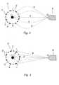
- Figs.2-4 are illustrative cross-sectional views of a stent and a core wire along with a spray nozzle and representative routes of charged coating formulation in embodiments of the method of the present invention.
- Fig.5 is a graph showing a cyclic change of the electrical potential applied to the core wire in an embodiment of the method of the present invention.
- Figs.6A and6B are illustrative cross-sectional views of a stent and a core wire along with a spray nozzle and representative routes of the charged coating formulation for two different states in the embodiment of the method of the present invention shown in Fig. 5.
- Fig.7 is an illustrative view of a spraying nozzle, a stent, a core wire, a pair of deflector plates, and representative routes of sprayed charged coating formulation, that are arranged for another embodiment of the method of the present invention.
- Fig.8 is an illustrative view of a spraying nozzle, a stent, a core wire, a pair of bobbins, and representative routes of sprayed charged coating formulation in yet another embodiment of the method of the present invention.
- In the method of the present invention, the amount of a coating formulation that is applied to a surface of a stent or tubular wall of a medical device is adjusted by employing the principles of electro-assisted spraying and a core wire located through the stent or tubular wall. The term "tubular wall" refers to a wall having a certain thickness configured in a shape of a tube or tubular structure. Such tubular structure may have a cross-section other than circle, such as an oval or square. In conventional electro-assisted spraying techniques, an electrically charged coating formulation is sprayed or applied to the surface of the device to be coated. The device is usually grounded or negatively charged. Since the coating formulation is a poor conductor, part of the electrical charge of the coating formulation is unable to escape. Therefore, those portions of the device surface that are coated with the coating formulation will have a higher potential than uncoated regions, and new particles or droplets of charged coating formulation applied to the device will be deflected to those uncoated regions of the device surface. In such method, the amount of coating formulation applied to the surface of the device tends to be uniformly spread over the entire surface. In contrast as explained further below, by locating an electrically charged core wire through the stent or tubular wall of the device, the amount of coating formulation applied on different surfaces or parts of a surface of the device can be varied.
- In one embodiment of the present invention, the coating formulation is in a form of droplets. In other embodiments of the present invention, the coating formulation is in a form of dry or wet powder-particles.
- Referring to Fig. 1, which depicts a perspective view of an arrangement for the method of the present invention wherein a conductive core wire12 is located axially through a
stent 10. Preferably, the core wire is located through the geometric center of the stent. Aspray nozzle 16 is placed in proximity of thestent 10 and an electrically chargedcoating formulation 14 is sprayed to thestent 10. - In an embodiment shown in Fig.2, a
stent 10 comprises astent wall 21 having aninner surface 22, anouter surface 24 and openings therein23. Thestent wall 21 is grounded by a ground line so that it becomes electrically neutral. A potential is applied to aconductive core wire 26 located axially through the geometric center of thestent 10 to impart a positive electrical charge to theconductive core wire 26. The coating formulation is positively charged and sprayed from thenozzle 16 toward thestent 10. Because of its positive electrical charge, the sprayed coating formulation is attracted to the groundedstent 10 and is deposited on theouter surface 24 and side portions of theopenings 23 of thestent wall 21. Representative routes of the sprayed charged coating formulation are shown as thearrows 28. The positively charged coating formulation does not enter theopenings 23 due to the electrical repulsion of the positively charged core wire. Therefore, the electrically charged coating formulation is deposited only on theouter surface 24 and the side portions of theopenings 23 of thestent wall 21, and theinner surface 22 of thestent wall 21 is maintained substantially free of coating. - In an embodiment shown in Fig.3, a
stent 10 comprises astent wall 21 having aninner surface 22, anouter surface 24 and openings therein23. Thestent wall 21 is grounded by a ground line so that it becomes electrically neutral. Aconductive core wire 26 located axially through the geometric center of thestent 10 is negatively charged. The coating formulation is positively charged and sprayed from thenozzle 16 toward thestent 10. Because of its positive electrical charge, the sprayed coating formulation is attracted to the groundedstent wall 21. Some of the coating formulation is deposited on theouter surface 24 of thestent wall 21, and some of the coating formulation passes through theopenings 23. Representative routes of the coating formulation are shown as thearrows 38. When the electrically charged coating formulation enters theopenings 23, it is accelerated by virtue of the electrical forces of attraction and are attracted toward theconductive core wire 26. Therefore, the coating formulation is deposited only on theouter surface 24 of thestent wall 21, and the side portion of theopenings 23 and theinner surface 22 of the stent are maintained substantially free of coating. - The embodiment shown in Fig.4 is ilustrative of how the method of the invention can be used to control how much coating is applied to the surface of a stent or a tubular wall. In this embodiment, a
stent 10 comprises astent wall 21 having aninner surface 22, anouter surface 24 and openings therein23. Thestent wall 21 is positively charged although its electrical potential is not high. Aconductive core wire 26 located axially through the geometric center of thestent 10 is negatively charged. The coating formulation is positively charged and sprayed from thenozzle 16 toward thestent 10. Because of its positive electrical charge, although the coating formulation is sprayed toward thestent 10, it is repelled by the positively chargedstent 10. Representative routes of the coating formulation are shown as thearrows 48. When the coating formulation enters theopenings 23, the coating formulation is attracted to the negatively chargedconductive core wire 16 as shown byarrows 47. Therefore, the coating formulation is not deposited either on theinner surface 22 or on theouter surface 24 of thestent wall 21, and the stent is maintained substantially free of coating. This embodiment may be used to stop further coating formulation from being deposited, for example, when a certain amount of coating has been reached. Also, this embodiment may be used to temporally stop coating the device for a period without stopping a continuous stable output from the nozzle. - In an embodiment shown in Figs.6A and6B, a
stent 10 comprises astent wall 21 having aninner surface 22, anouter surface 24 and openings therein23. Thestent wall 21 is positively charged although its electrical potential is not high. Aconductive core wire 26 is located axially through the geometric center of thestent 10. The coating formulation is positively charged and sprayed from thenozzle 16 toward thestent 10. The electrical potential applied to theconductive core wire 26 is repeatedly altematived between positive and negative as shown in the graph of Fig.5. In Fig.5, at first, the electrical potential of the conductive core wire is negative (State A) for a certain period, and changes to positive (State B), and again changes to negative (State A). States A and B are repeated in turn. Fig.6A shows State A, wherein thestent wall 21 is positively charged (the electrical potential is not high), and theconductive core wire 26 is negatively charged. The coating formulation is positively charged and sprayed from thenozzle 16 toward thestent 10. Because of its positive electrical charge, although the coating formulation is sprayed toward thestent 10, majority of particles or droplets are repelled by the positively chargedstent 10 as shownarrows 68. When particles or droplets of the coating formulation enter in theopenings 23, the particles or droplets are attracted to the negatively chargedconductive core wire 16 as shown byarrows 67. Therefore, the coating formulation are not deposited either on theinner surface 22 or on theouter surface 24 of thestent wall 21, and the stent is maintained substantially free of coating. - Fig.6B shows State B, wherein the
stent wall 21 is still positively charged as in State A, but theconductive core wire 26 is also positively charged. The electrical potential of theconductive core wire 26 is higher than that of thestent wall 21. The coating formulation is positively charged and sprayed from thenozzle 16 toward thestent 10. Because of its positive electrical charge, although the coating formulation is sprayed toward thestent 10, it is repelled by the positively chargedstent 10 as shown byarrows 65. However, there is the coating formulation inside thestent 10 which was being attracted to but had not yet reached the then-negatively chargedconductive core wire 26 in State A. The coating formulation inside thestent 10 is repelled by thecore wire 26, which is now positively charged, and the coating formulation is deposited on theinner surface 22 of thestent wall 21 in State B. Therefore, in this embodiment, the coating formulation is deposited on theinner surface 22, and theouter surface 24 of thestent wall 21 is maintained substantially free of coating. Skilled artisans can optimize the electrical potentials (voltage) of theconductive core wire 26, thestent 10 and the coating formulation and the cycle (frequency) of the potential change to adjust the amount of coating applied to theinner surface 22 of thestent wall 21. Generally, the time period of State A is longer than that of State B. The period of State A is preferably long enough for sufficient amount of coating formulation to enter in thestent wall 21 through theopenings 23 but shorter than necessary for the coating formulation to reach theconductive core wire 26. The period of State B is preferably not more than enough for substantially all coating formulation inside thestent wall 21 to be deposited on theinner surface 22 of thestent wall 21. - Each embodiment of the method of the present invention explained above can be conducted alone. The embodiment shown in Fig.2 can be used to coat the outer surface and the side portions of the openings of a stent wall. The embodiment shown in Fig.3 can be used to coat the outer surface of a stent wall. The embodiment shown in Figs.6A and6B can be used to coat the inner surface of a stent wall.
- Also, however, those embodiments may be combined, if desired. Particularly, the electrical potential applied to the stent wall may be repeatedly alternated between neutral and positive, and so may the electrical potential applied to the conductive core wire. By adjusting the frequency of the alternation and each electrical potential (voltage), it is possible to obtain any ratio of coating thickness on the inner surface, the outer surface and the side portions of the openings of the stent wall by using a continuous flow of sprayed coating formulation. For example, the following states may be employed to coat the device. Each state is part of a cycle, which can be repeated. During each of the states, the coating formulation remains positively charged:
- State A:
- The stent wall has a positive electrical charge, but the potential applied to it is lower than that of the coating formulation. The conductive core wire has a negative electrical charge. (See Fig.6A)
- State B:
- The stent wall has a positive electrical charge, and the conductive core wire has a positive electrical charge. The potential of the stent wall is lower than that of the coating formulation and the conductive core wire. (See Fig.6B)
- State C:
- The stent wall is grounded, and the conductive core wire has a positive electrical charge. (See Fig. 2)
- State D:
- The stent wall is grounded, and the conductive core wire has a negative electrical charge. (See Fig. 3)
- State E:
- The stent wall has a positive electrical charge, but the potential applied to it is lower than that of the coating formulation. The conductive core wire has a negative electrical charge. (See Fig.4)
- Moreover, the coating formulation may be negatively charged instead of being positively charged. If the coating formulation is negatively charged, then the stent is grounded or negatively charged, and the electrical potentials of the conductive core wire explained in the above embodiments are reversed.
- Further, by adjusting time necessary for the coating formulation to reach to the surface to be coated in the above embodiments, it is possible to control the wetness of the coating formulation that arrive at a surface. The time can be adjusted by increasing or decreasing the field strength, specifically the electrical potentials of the coating formulation, the stent and the conductive core wire. If it takes longer for the coating formulation to get from the nozzle to the surface, then the coating formulation is dryer when it reaches the surface. If it takes less time for the coating formulation to get from nozzle to the surface, then the coating formulation is wetter when it reaches the surface. An appropriate wetness of the coating formulation must be chosen to obtain a coating layer which has desired physical properties and desired release profile of the biologically active material. For example, by choosing an appropriate wetness of the coating formulation in liquid form, it is possible to control the coating porosity. Such ability to control porosity is useful for preparing a coating for release a biologically active material.
- In embodiments of the method of the present invention, a stent can be coated with a multiple coating layers of the same coating formulation. Such coating layers may be made by using the above mentioned method repeatedly. The thickness of each coating layer can be controlled as explained above. Also, the coating comprises various coating layers of different coating formulations. Such different coating layers can be efficiently made by using the present invention. For example, a first nozzle containing a first coating formulation may be first used to coat the outer surface of a stent by the above-mentioned embodiment of the method of the present invention, and then a second nozzle containing a second coating formulation may be used to coat the outer surface which is already coated with the first coating formulation. If desired, it is possible to coat a surface with the first coating formulation and coat the other surface with the second coating formulation which is different from the first coating formulation.
- In addition to controlling the ratio of coating thickness on the inner surface, the outer surface and the side portions of the openings of the stent wall, the coating thickness along the longitudinal axis of a stent or a tubular wall can be controlled by an embodiment of the method of the present invention. Referring to Fig.7, a pair of
deflector plates first deflector plate 72a having a negative electrical charge and asecond deflector plate 72b having a positive electrical charge, which are parallel to each other. The pair ofdeflector plates nozzle 16 toward thestent 10. The positively charged coating formulation is attracted to the negatively chargeddeflector plate 72a and the course of the charged coating formulation is deflected toward thedeflector plate 72a as shown byarrow 77. However, the electrical potential between thedeflector plates deflector plate 72a. The distribution of the coating formulation on thestent wall 21 in its longitudinal direction can be controlled by using the deflector plates. For example, a stent having a coating which covers only one edge or end section of the stent can be obtained. If the potential is reversed, then the other edge or end section will also be covered by the coating, and a stent having a thicker coating at both end sections and thinner coating in the middle section can be obtained. The term "end section" of the outer surface refers to that part of the surface which extends from an end section or edge of a stent or a tubular wall up to about 25%, preferably from about 3 % to about 20 % of the entire length of the outer surface. The term "middle section" refers to the remainder of the outer surface that is surrounded by the end sections as defined above. - When the potential is reversed, the coating formulation may be switched from the first coating formulation to the second coating formulation so that a tubular wall can have a different type of coating on its end sections. By using different electrical potentials and varying the time such potentials are applied, sophisticated control of the coating can be achieved. For example, coating only a horizontal belt-like portion of the tubular wall or horizontal stripes of the tubular wall, is possible by adjusting the potential between the pair of deflector plates and adjusting the position of the deflector plates relative to the tubular wall.
- When the electrical charge of the conductive core wire is opposite to that of the sprayed coating formulation, the coating formulation can be deposited on the conductive core wire in the method of the present invention. Since the coating formulation has poor conductivity, the electrical potential of the wire becomes weaker as more coating formulation accumulates on the wire. To prevent such weakening potential of the conductive core wire, the wire is preferably kept substantially free from the coating formulation. For example, a pair of bobbins can be used to feed new conductive core wire through a stent as shown in Fig.8. A
first bobbin 82a on which a substantial length of conductive core wire is wound is one side of thestent 10 and theconductive core wire 26 is passed axially through thestent 10 and the other end section of theconductive core wire 26 is connected to asecond bobbin 82b. As a portion of the conductive core wire is constantly unwound from thefirst bobbin 82a and fed through thestent 10, the conductive core wire covered with the coating formulation is removed and connected to thesecond bobbin 82b. - In one embodiment of the method of the present invention, a core wire made of a resistor material is used instead of a conductive core wire, and a current is directed through the wire. Since the potential of the core wire comprised of a resistor material is a function of the longitudinal position along the core wire, more electrically charged coating formulation is deposited on the portion of the surface of the tubular wall that is closer to the part of the core wire having higher opposite potential to the charged coating formulation. If two parallel core wires of resistor material are provided in a stent wherein opposing currents are directed, a stent having thicker coating at both end sections and thinner coating in the middle section can be obtained. A pair of bobbins or a pair of deflector plates explained above can also be used for core wires made of a resistor material.
- Although the above embodiments of the method of the present invention are explained using a stent as an example of a medical device having a tubular wall, the method of the present invention can be used generally for coating at least a portion of a surface of a medical device comprising a tubular wall having an inner surface and an outer surface and openings therein. A preferable medical device is designed to be inserted or implanted into the body of a patient. Such medical devices suitable for the present invention include, but are not limited to, stents, vascular or other grafts, and filters, such as blood filters.
- Medical devices which are particularly suitable for the present invention include stents, for example, vascular stents such as self-expanding stents and balloon expandable stents. Stents suitable for the present invention include any stent for medical purposes, which are known to the skilled artisans. Particularly the method of the present invention is useful for coating stents having intricate surfaces. Examples of self-expanding stents useful in the present invention are illustrated in U.S. Patent Nos. 4,655,771 and 4,954,126 issued to Wallsten and 5,061,275 issued to Wallstenet al. Examples of appropriate balloon-expandable stents are shown in U.S. Patent No. 5,449,373 issued to Pinchasiket al.
- The medical devices suitable for the present invention may be fabricated from conductive materials, such as conductive ceramic, polymeric and metallic materials. The surface(s) of the medical devices to be coated using the process of the present invention should be fabricated from conductive materials. Suitable metallic materials include metals and alloys based on titanium (such as nitinol, nickel titanium alloys, thermo-memory alloy materials), stainless steel, tantalum, nickel-chrome, or certain cobalt alloys including cobalt-chromium-nickel alloys such as Elgiloy® and Phynox®. Metallic materials also include clad composite filaments, such as those disclosed in WO 94/16646. An example of a suitable ceramic is carbide. Polymers can be used to fabricate the medical device when they are conductive. These include polymers filled with carbon-nanotubes. Carbon-nanotubes are commercially available, e.g., from CARBOLEX. Only the surface to be coated rather than entire medical device may be fabricated from a conductive material.
- The core wire can be made of a conductive material. The surface of core wire should be conductive. Suitable conductive materials include those described materials for the medical device. In an embodiment of the method of the present invention, the core wire is made of a resistor material, such as carbon, a polymer filled with carbon nanotubes.
- Any spraying nozzle or spraying device that can spray coating formulation and create particles or droplets of an appropriate size and of appropriate electrical charge is useful for the method of the present invention. Examples of such spraying nozzle are disclosed in U.S. Patent No. 4,341,347 to DeVittorio, U.S. Patent No. 4,004,733 to Law, U.S. Patent 4,215,818 to Hopkinson, and U.S. Patent No. 4,002,777 to Juvinallet al. One preferable example of a spraying nozzle that can be used in the method of the invention is an apparatus for electrohydrodynamic spray-coating that is disclosed in U.S. Patent No. 4,749,125, to Escallonet al.
- Coating formulations that are useful for the method of the present invention may be a solution or a suspension comprises a polymeric material and solvent or may be powder comprising a polymeric material. The polymeric material useful for forming the coating formulation should be ones that are biocompatible and avoids irritation to body tissue. Preferably the polymeric materials are biostable ones, such as polyurethanes, silicones (e.g., polysiloxanes and substituted polysiloxanes), and polyesters. Also preferable as a polymeric material is styrene-isobutylene copolymers. Other polymers which can be used include ones that can be dissolved and cured or polymerized on the medical device or polymers having relatively low melting points that can be blended with biologically active materials. Additional suitable polymers include, thermoplastic elastomers in general, polyolefins, polyisobutylene, ethylene-alphaolefin copolymers, acrylic polymers and copolymers, vinyl halide polymers and copolymers such as polyvinyl chloride, polyvinyl ethers such as polyvinyl methyl ether, polyvinylidene halides such as polyvinylidene fluoride and polyvinylidene chloride, polyacrylonitrile, polyvinyl ketones, polyvinyl aromatics such as polystyrene, polyvinyl esters such as polyvinyl acetate, copolymers of vinyl monomers, copolymers of vinyl monomers and olefins such as ethylene-methyl methacrylate copolymers, acrylonitrile-styrene copolymers, ABS (acrylonitrile-butadiene-styrene) resins, ethylene-vinyl acetate copolymers, polyamides such as Nylon 66, Nylon 12 and polycaprolactone, alkyd resins, polycarbonates, polyoxymethylenes, polyimides, polyethers, epoxy resins, rayon-triacetate, cellulose, cellulose acetate, cellulose butyrate, cellulose acetate butyrate, cellophane, cellulose nitrate, cellulose propionate, cellulose ethers, carboxymethyl cellulose, collagens, chitins, polylactic acid, polyglycolic acid, polylactic acid-polyethylene oxide copolymers, EPDM (etylene-propylene-diene) rubbers, fluorosilicones, polyethylene glycol, polysaccharides, phospholipids, combinations of the foregoing.
- More preferably for medical devices which undergo mechanical challenges, e.g. expansion and contraction, the polymeric materials should be selected from elastomeric polymers such as silicones (e.g. polysiloxanes and substituted polysiloxanes), polyurethanes, thermoplastic elastomers, ethylene vinyl acetate copolymers, polyolefin elastomers, and EPDM rubbers. Because of the elastic nature of these polymers, the coating adheres better to the surface of the medical device when the device is subjected to forces, stress or mechanical challenge.
- Furthermore, although the invention can be practiced by using a single type of polymer to form the coating layer(s), various combinations of polymers can be employed. The appropriate mixture of polymers can be coordinated with biologically active materials of interest to produce desired effects when coated on a medical device in accordance with the invention.
- Coating formulations useful for the present invention may contain a nanocomposite instead of or in addition to a polymeric material explained above. "Nanocomposite" is a term of art that refers to a composition comprising a polymeric material and relatively small amounts (generally less than about 10 % by weight) of nanometer-sized (average size smaller than 1 micrometer) mineral clay or nanosized ceramic particles dispersed therein. Sometimes nanocomposites are refered to as "nanoclay" or "nanoceramic". For example, nanocomposites are disclosed in WO 931014118, U.S. Patent Nos. 5,385,776, and 6,251,980.
- Solvents suitable for forming the coating formulation are ones which can dissolve the polymeric material into solution or form dispersions of the polymeric material in the solvent. Any solvent which does not alter or adversely impact the therapeutic properties of the biologically active material can be employed in the method of the present invention. Examples of useful solvents include tetrahydrofuran, chloroform, toluene, acetone, isooctane, 1,1,1,-trichloroethane, and mixture thereof. Preferably, chloroform or tetrahydrofuran is used as the solvent in the method of the present invention.
- Coating formulations useful for the present invention that are in powder form can comprise a polymeric material as explained above. The powder is preferably comprised of particles having an average diameter from about 0.5 µm to about 250 µm. Generally, the resulting surface of the coating is smoother when the powder of the coating formulation used for the coating has a smaller average particle size. After the spray-coating step using the powder coating fonnulation, the tubular wall coated with the powder coating formulation is heat-treated, for example using IR heating.
- Even when the coating formulation used for the present invention contains a solvent, it is possible to control the process to dry the sprayed coating formulation before they reach the tubular wall of the medical device by controlling the method as explained earlier. In this manner, results similar to those of the process using dry-powder coating formulation can be obtained by using the coating formulation containing a solvent.
- Coating formulations useful for the method of the present invention may also comprise a biologically active material. The term "biologically active material" encompasses therapeutic agents, such as drugs, and also genetic materials and biological materials. The genetic materials mean DNA or RNA, including, without limitation, of DNA/RNA encoding a useful protein stated below, anti-sense DNA/RNA, intended to be inserted into a human body including viral vectors and non-viral vectors. Examples of DNA suitable for the present invention include DNA encoding
- anti-sense RNA
- tRNA or rRNA to replace defective or deficient endogenous molecules
- angiogenic factors including growth factors, such as acidic and basic fibroblast growth factors, vascular endothelial growth factor, epidermal growth factor, transforming growth factor α and β, platelet-derived endothelial growth factor, platelet-derived growth factor, tumor necrosis factor α, hepatocyte growth factor and insulin like growth factor
- cell ccle inhibitors including CD inhibitors
- thymidine kinase ("TK") and other agents useful for interfering with cell proliferation, and
- the family of bone morphogenic proteins ("BMP's") as explained below.
- The biological materials include cells, yeasts, bacteria, proteins, peptides, cytokines and hormones. Examples for peptides and proteins include growth factors (FGF, FGF-1, FGF-2, VEGF, Endotherial Mitogenic Growth Factors, and epidermal growth factors, transforming growth factor α and β, platelet derived endothelial growth factor, platelet derived growth factor, tumor necrosis factor α, hepatocyte growth factor and insulin like growth factor), transcription factors, proteinkinases, CD inhibitors, thymidine kinase, and bone morphogenic proteins (BMP's), such as BMP-2, BMP-3, BMP-4, BMP-5, BMP-6 (Vgr-1), BMP-7 (OP-1), BMP-8. BMP-9, BMP-10, BMP-11, BMP-12, BMP-13, BMP-14, BMP-15, and BMP-16. Currently preferred BMP's are BMP-2, BMP-3, BMP-4, BMP-5, BMP-6, BMP-7. Alternatively or in addition, molecules capable of inducing an upstream or downstream effect of a BMP can be provided. Such molecules include any of the "hedgehog" proteins, or the DNA's encoding them. These dimeric proteins can be provided as homodimers, heterodimers, or combinations thereof, alone or together with other molecules. Cells can be of human origin (autologous or allogeneic) or from an animal source (xenogeneic), genetically engineered, if desired, to deliver proteins of interest at the transplant site. The delivery media can be formulated as needed to maintain cell function and viability. Cells include whole bone marrow, bone marrow derived mono-nuclear cells, progenitor cells (e.g., endothelial progentitor cells) stem cells (e.g., mesenchymal, hematopoietic, neuronal), pluripotent stem cells, fibroblasts, macrophage, and satellite cells.
- Biologically active material also includes non-genetic therapeutic agents, such as:
- anti-thrombogenic agents such as heparin, heparin derivatives, urokinase, and PPack (dextrophenylalanine proline arginine chloromethylketone);
- anti-proliferative agents such as enoxaprin, angiopeptin, or monoclonal antibodies capable of blocking smooth muscle cell proliferation, hirudin, and acetylsalicylic acid, amlodipine and doxazosin;
- anti-inflammatory agents such as glucocorticoids, betamethasone, dexamethasone, prednisolone, corticosterone, budesonide, estrogen, sulfasalazine, and mesalamine;
- immunosuppressants such as sirolimus (RAPAMYCIN), tacrolimus, everolimus and dexamethasone,
- antineoplastic/antiproliferative/anti-miotic agents such as paclitaxel, 5-fluorouracil, cisplatin, vinblastine, vincristine, epothilones, methotrexate, azathioprine, halofuginone, adriamycin, actinomycin and mutamycin; endostatin, angiostatin and thymidine kinase inhibitors, and its analogs or derivatives;
- anesthetic agents such as lidocaine, bupivacaine, and ropivacaine;
- anti-coagulants such as D-Phe-Pro-Arg chloromethyl keton, an RGD peptide-containing compound, heparin, antithrombin compounds, platelet receptor antagonists, anti-thrombin anticodies, anti-platelet receptor antibodies, aspirin (aspirin is also classified as an analgesic, antipyretic and anti-inflammatory drug), dipyridamole, protamine, hirudin, prostaglandin inhibitors, platelet inhibitors and tick antiplatelet peptides;
- vascular cell growth promotors such as growth factors, Vascular Endothelial Growth Factors (FEGF, all types including VEGF-2), growth factor receptors, transcriptional activators, and translational promotors;
- vascular cell growth inhibitors such as antiproliferative agents, growth factor inhibitors, growth factor receptor antagonists, transcriptional repressors, translational repressors, replication inhibitors, inhibitory antibodies, antibodies directed against growth factors, bifunctional molecules consisting of a growth factor and a cytotoxin, bifunctional molecules consisting of an antibody and a cytotoxin;
- cholesterol-lowering agents; vasodilating agents; and agents which interfere with endogenous vasoactive mechanisms;
- anti-oxidants, such as probucol;
- antibiotic agents, such as penicillin, cefoxitin, oxacillin, tobranycin
- angiogenic substances, such as acidic and basic fibrobrast growth factors, estrogen including estradiol (E2), estriol (E3) and 17-Beta Estradiol; and
- drugs for heart failure, such as digoxin, beta-blockers, angiotensin-converting enzyme (ACE) inhibitors including captopril and enalopril.
- Also, the biologically active materials of the present invention include nitric oxide adducts, which prevent and/or treat adverse effects associated with use of a medical device in a patient, such as restenosis and damaged blood vessel surface. Typical nitric oxide adducts include nitroglycerin, sodium nitroprusside, S-nitroso-proteins, S-nitroso-thiols, long carbon-chain lipophilic S-nitrosothiols, S-nitrosodithiols, iron-nitrosyl compounds, thionitrates, thionitrites, sydnonimines, furoxans, organic nitrates, and nitrosated amino acids, preferably mono-or poly-nitrosylated proteins, particularly polynitrosated albumin or polymers or aggregates thereof. The albumin is preferably human or bovine, including humanized bovine serum albumin. Such nitric oxide adducts are disclosed in U.S. Patent No. 6,087,479 to Stamleret al.
- A biologically active material may be encapsulated in micro or nano-capsules by the known methods.
- The biologically active material can be used with (a) biologically non-active material(s) including a carrier or an excipient, such as sucrose acetate isobutyrate (SABER™ commercially available from SBS) ethanol, n-methyl pymolidone, dimethyl sulfoxide, benzyl benxoate, benzyl acetate, albumine, carbohydrate, and polysacharide. Also, nanoparticles of the biologically active materials and non-active materials are useful for the coating formulation of the present invention.
- The description contained herein is for purposes of illustration and not for purposes of limitation. Changes and modifications may be made to the embodiments of the description and still be within the scope of the invention as defined by the appended claims. Furthermore, obvious changes, modifications or variations will occur to those skilled in the art.
Claims (33)
- A method for coating a medical device (10) comprising a tubular wall (21) having an inner surface (22), an outer surface (24) and openings (23) therein, the method comprising the following steps:(a) grounding or electrically charging the tubular wall (21);(b) exposing the tubular wall (21) to an electrically charged coating formulation (14); and(c) depositing the coating formulation (14) onto a portion of the tubular wall (21) to form a coating on the tubular wall (21);characterised by(d) providing a conductive core (12, 26) wire located axially through the tubular wall (21);(e) applying a potential to the conductive core wire (12, 26) to impart an electrical charge to the conductive core wire (12, 26).
- The method of claim 1, wherein the coating formulation (14) comprises a polymeric material and a solvent.
- The method of claim 1 or 2, wherein the coating formulation (14) comprises a biologically active material.
- The method of claim 3, wherein the biologically active material comprises an immunosuppressant, an anti-proliferative agent, or a combination thereof.
- The method of claim 4, wherein the immunosuppressant comprises sirolimus, everolimus, tacrolimus, or a combination thereof.
- The method of claim 4, wherein the anti-proliferative agent comprises paclitaxel, an analog thereof, a derivative thereof, or a combination thereof.
- The method of claim 3, wherein the biologically active material comprises genetic material.
- The method of any of the claims 1 to 7, wherein the electrical charge of the tubular wall (21) is positive and the electrical charge of the coating formulation (14) is opposite to the electrical charge of the core wire (12,26).
- The method of claim 8, wherein the conductive core wire (12, 26) has the opposite charge as the tubular wall (21).
- The method of claim 8, further comprising adjusting the electrical charge of the conductive wire (12, 26) so that the charged coating formulation (14) is deposited on the inner surface (22) of the tubular wall and the outer surface (24) remains substantially free of the charged coating formulation (14).
- The method of claim 1 to 8, wherein the medical device is a stent (10) and wherein at least a portion of the stent (10) is coated.
- The method of claim 1, wherein the tubular wall (21) is grounded, and the conductive core wire (12, 26) and the coating formulation (14) have the same electrical charge.
- The method of claim 3, wherein the electrical charge of the coating formulation (14) and the electrical charge of the conductive core wire (12, 26) are adjusted so that the charged coating formulation (14) are deposited on the outer surface (24) of the tubular wall (21) and the inner surface (22) remains substantially free of the charged coating formulation (14).
- The method of claim 1, wherein the tubular wall (21) is grounded, and the conductive core wire (12, 26) has an electrical charge opposite that of the coating formulation (14).
- The method of claim 1, wherein the tubular wall (21) comprises a geometric center, and the conductive core wire (12, 26) is located axially through the center of the tubular wall (21).
- The method of claim 1, wherein the potential applied to the conductive core wire (12, 26) is pulsated to cyclically impart a positive electrical charge to the conductive core wire (12, 26) followed by a negative electrical charge.
- The method of claim 16, wherein a positive electrical charge imparted to the conductive core wire (12, 26) is for a shorter duration than the negative electrical charge imparted to the conductive core wire (12, 26).
- The method of claim 1, wherein the conductive core wire (12, 26) is kept substantially free of the charged coating formulation (14).
- The method of claim 1, wherein the conductive core wire (26) has two ends and one end of the conductive core wire (26) is connected to a first bobbin (82a) and the other end is connected to a second bobbin (82b), wherein the conductive core wire (26) is fed from the first bobbin (82a) through the stent (10), and wherein the conductive core wire (26) covered with the coating formulation (14) is removed from the stent (10) by being connected to the second bobbin (82b).
- The method of claim 1, which further comprises directing the charged coating formulation (14) by providing (a) a first deflector plate (72a) having a positive electrical charge and a second deflector plate (72b) having a negative electrical charge, which are placed parallel to each other and (b) applying the charged coating formulation (14) between the plates.
- The method of claim 7 16, wherein the coating formulation (14) has a positive electrical charge, and an electrical potential applied to the tubular wall (21) is repeatedly alternated between grounded and positively charged to deposit a desired amount of the coating formulation (14) on each portion of the tubular wall (21).
- A method for coating a medical device (10) comprising a tubular wall (21) having an inner surface (22), an outer surface (24) and openings (23) therein, the method comprising the following steps:(a) grounding or electrically charging the tubular wall (21);(b) creating an electrically charged coating formulation (14); and(c) depositing the coating formulation (14) onto the tubular wall (21) to form a coating on the tubular wall (21);characterised by(d) providing a first core wire (12, 26) comprising a resistor material located axially through the tubular wall (21);(e) directing a current through the first core wire (12, 26).
- The method of claim 22, wherein the coating formulation (14) comprises a polymeric material and a solvent.
- The method of claim 22 or 23, wherein the wherein the coating formulation (14) comprises a biologically active material.
- The method of claim 24, wherein the biologically active material comprises an immunosuppressant, an anti-proliferative agent, or a combination thereof.
- The method of claim 25, wherein the immunosuppressant comprises sirolimus, everolimus, tacrolimus, or a combination thereof.
- The method of claim 25, wherein the anti-proliferative agent comprises paclitaxel, an analog thereof, a derivative thereof, or a combination thereof.
- The method of claim 24, wherein the biologically active material comprises genetic material.
- A method according to any of the claims 22 to 28, wherein the electrical charge of the tubular wall (21) is positive and the electrical charge of the coating formulation (14) is also positive.
- The method of claim 22, wherein the tubular wall (21) comprises two end sections and wherein a greater amount of coating formulation (14) is applied to one end section than the other.
- The method of claim 22, which further comprises providing a second core wire comprising a resistor material through the stent (10) wherein the second core wire is parallel to the first core wire; and directing second current through the second core wire in a direction opposite the first current.
- The method of claim 22, wherein the first core wire is kept substantially free of the coating formulation.
- The method of claim 22, wherein the first core wire comprising two ends and one end of the first core wire is connected to a first bobbin (82a) and the other end is connected to a second bobbin (82b), wherein the first core wire is fed from the first bobbin (82a) through the stent (10), and wherein the first core wire covered with the coating formulation (14) is removed from the stent (10) by being connected to the second bobbin (82b).
Priority Applications (1)
| Application Number | Priority Date | Filing Date | Title |
|---|---|---|---|
| EP06022708AEP1743662A3 (en) | 2002-03-28 | 2003-03-26 | Method for spray-coating a stent |
Applications Claiming Priority (3)
| Application Number | Priority Date | Filing Date | Title |
|---|---|---|---|
| US109073 | 2002-03-28 | ||
| US10/109,073US6743463B2 (en) | 2002-03-28 | 2002-03-28 | Method for spray-coating a medical device having a tubular wall such as a stent |
| PCT/US2003/009036WO2003082363A1 (en) | 2002-03-28 | 2003-03-26 | Method for spray-coating a tubular medical device |
Related Child Applications (1)
| Application Number | Title | Priority Date | Filing Date |
|---|---|---|---|
| EP06022708ADivisionEP1743662A3 (en) | 2002-03-28 | 2003-03-26 | Method for spray-coating a stent |
Publications (3)
| Publication Number | Publication Date |
|---|---|
| EP1496954A1 EP1496954A1 (en) | 2005-01-19 |
| EP1496954A4 EP1496954A4 (en) | 2005-06-22 |
| EP1496954B1true EP1496954B1 (en) | 2006-11-02 |
Family
ID=28453001
Family Applications (2)
| Application Number | Title | Priority Date | Filing Date |
|---|---|---|---|
| EP06022708AWithdrawnEP1743662A3 (en) | 2002-03-28 | 2003-03-26 | Method for spray-coating a stent |
| EP03718045AExpired - LifetimeEP1496954B1 (en) | 2002-03-28 | 2003-03-26 | Method for spray-coating a tubular medical device |
Family Applications Before (1)
| Application Number | Title | Priority Date | Filing Date |
|---|---|---|---|
| EP06022708AWithdrawnEP1743662A3 (en) | 2002-03-28 | 2003-03-26 | Method for spray-coating a stent |
Country Status (5)
| Country | Link |
|---|---|
| US (3) | US6743463B2 (en) |
| EP (2) | EP1743662A3 (en) |
| AU (1) | AU2003222061A1 (en) |
| DE (1) | DE60309460T2 (en) |
| WO (1) | WO2003082363A1 (en) |
Families Citing this family (287)
| Publication number | Priority date | Publication date | Assignee | Title |
|---|---|---|---|---|
| US6774278B1 (en)* | 1995-06-07 | 2004-08-10 | Cook Incorporated | Coated implantable medical device |
| US6776792B1 (en) | 1997-04-24 | 2004-08-17 | Advanced Cardiovascular Systems Inc. | Coated endovascular stent |
| US6433154B1 (en)* | 1997-06-12 | 2002-08-13 | Bristol-Myers Squibb Company | Functional receptor/kinase chimera in yeast cells |
| US20030129215A1 (en)* | 1998-09-24 | 2003-07-10 | T-Ram, Inc. | Medical devices containing rapamycin analogs |
| US6890546B2 (en) | 1998-09-24 | 2005-05-10 | Abbott Laboratories | Medical devices containing rapamycin analogs |
| US7208010B2 (en) | 2000-10-16 | 2007-04-24 | Conor Medsystems, Inc. | Expandable medical device for delivery of beneficial agent |
| US7208011B2 (en)* | 2001-08-20 | 2007-04-24 | Conor Medsystems, Inc. | Implantable medical device with drug filled holes |
| US6241762B1 (en)* | 1998-03-30 | 2001-06-05 | Conor Medsystems, Inc. | Expandable medical device with ductile hinges |
| US7713297B2 (en) | 1998-04-11 | 2010-05-11 | Boston Scientific Scimed, Inc. | Drug-releasing stent with ceramic-containing layer |
| US7807211B2 (en) | 1999-09-03 | 2010-10-05 | Advanced Cardiovascular Systems, Inc. | Thermal treatment of an implantable medical device |
| US20070032853A1 (en) | 2002-03-27 | 2007-02-08 | Hossainy Syed F | 40-O-(2-hydroxy)ethyl-rapamycin coated stent |
| US20050238686A1 (en)* | 1999-12-23 | 2005-10-27 | Advanced Cardiovascular Systems, Inc. | Coating for implantable devices and a method of forming the same |
| US7419678B2 (en)* | 2000-05-12 | 2008-09-02 | Cordis Corporation | Coated medical devices for the prevention and treatment of vascular disease |
| DE60135455D1 (en) | 2000-05-16 | 2008-10-02 | Univ Minnesota | IT OF MULTI-NOZZLE ARRANGEMENT |
| US6953560B1 (en) | 2000-09-28 | 2005-10-11 | Advanced Cardiovascular Systems, Inc. | Barriers for polymer-coated implantable medical devices and methods for making the same |
| EP1498084B1 (en)* | 2000-10-16 | 2014-06-18 | Innovational Holdings, LLC | Expandable medical device for delivery of beneficial agent |
| US6783793B1 (en) | 2000-10-26 | 2004-08-31 | Advanced Cardiovascular Systems, Inc. | Selective coating of medical devices |
| US20040073294A1 (en) | 2002-09-20 | 2004-04-15 | Conor Medsystems, Inc. | Method and apparatus for loading a beneficial agent into an expandable medical device |
| US7247338B2 (en)* | 2001-05-16 | 2007-07-24 | Regents Of The University Of Minnesota | Coating medical devices |
| US7862495B2 (en)* | 2001-05-31 | 2011-01-04 | Advanced Cardiovascular Systems, Inc. | Radiation or drug delivery source with activity gradient to minimize edge effects |
| WO2003002243A2 (en) | 2001-06-27 | 2003-01-09 | Remon Medical Technologies Ltd. | Method and device for electrochemical formation of therapeutic species in vivo |
| US6565659B1 (en) | 2001-06-28 | 2003-05-20 | Advanced Cardiovascular Systems, Inc. | Stent mounting assembly and a method of using the same to coat a stent |
| US6656216B1 (en)* | 2001-06-29 | 2003-12-02 | Advanced Cardiovascular Systems, Inc. | Composite stent with regioselective material |
| EP1275442A1 (en)* | 2001-07-13 | 2003-01-15 | Stichting voor de Technische Wetenschappen | Electrostatic spray deposition (ESD) of biocompatible coatings on metallic substrates |
| US7842083B2 (en) | 2001-08-20 | 2010-11-30 | Innovational Holdings, Llc. | Expandable medical device with improved spatial distribution |
| US7056338B2 (en)* | 2003-03-28 | 2006-06-06 | Conor Medsystems, Inc. | Therapeutic agent delivery device with controlled therapeutic agent release rates |
| US6669980B2 (en)* | 2001-09-18 | 2003-12-30 | Scimed Life Systems, Inc. | Method for spray-coating medical devices |
| US6939376B2 (en)* | 2001-11-05 | 2005-09-06 | Sun Biomedical, Ltd. | Drug-delivery endovascular stent and method for treating restenosis |
| US7682387B2 (en)* | 2002-04-24 | 2010-03-23 | Biosensors International Group, Ltd. | Drug-delivery endovascular stent and method for treating restenosis |
| KR20030043780A (en)* | 2001-11-28 | 2003-06-02 | 주식회사 바이오폴리메드 | Biologically active non-antigenic copolymer and conjugates thereof and methods for producing the same |
| US20040024450A1 (en)* | 2002-04-24 | 2004-02-05 | Sun Biomedical, Ltd. | Drug-delivery endovascular stent and method for treating restenosis |
| US7758636B2 (en)* | 2002-09-20 | 2010-07-20 | Innovational Holdings Llc | Expandable medical device with openings for delivery of multiple beneficial agents |
| US7125577B2 (en)* | 2002-09-27 | 2006-10-24 | Surmodics, Inc | Method and apparatus for coating of substrates |
| USRE40722E1 (en) | 2002-09-27 | 2009-06-09 | Surmodics, Inc. | Method and apparatus for coating of substrates |
| US7192484B2 (en) | 2002-09-27 | 2007-03-20 | Surmodics, Inc. | Advanced coating apparatus and method |
| US7208190B2 (en)* | 2002-11-07 | 2007-04-24 | Abbott Laboratories | Method of loading beneficial agent to a prosthesis by fluid-jet application |
| US8221495B2 (en)* | 2002-11-07 | 2012-07-17 | Abbott Laboratories | Integration of therapeutic agent into a bioerodible medical device |
| US8524148B2 (en)* | 2002-11-07 | 2013-09-03 | Abbott Laboratories | Method of integrating therapeutic agent into a bioerodible medical device |
| AU2003291470A1 (en)* | 2002-11-08 | 2004-06-03 | Innovational Holdings, Llc | Expandable medical device and method for treating chronic total occlusions with local delivery of an angiogenic factor |
| US6896965B1 (en) | 2002-11-12 | 2005-05-24 | Advanced Cardiovascular Systems, Inc. | Rate limiting barriers for implantable devices |
| US6982004B1 (en) | 2002-11-26 | 2006-01-03 | Advanced Cardiovascular Systems, Inc. | Electrostatic loading of drugs on implantable medical devices |
| US7844347B2 (en)* | 2002-12-06 | 2010-11-30 | Medtronic, Inc. | Medical devices incorporating carbon nanotube material and methods of fabricating same |
| US20060002968A1 (en)* | 2004-06-30 | 2006-01-05 | Gordon Stewart | Anti-proliferative and anti-inflammatory agent combination for treatment of vascular disorders |
| US7758881B2 (en) | 2004-06-30 | 2010-07-20 | Advanced Cardiovascular Systems, Inc. | Anti-proliferative and anti-inflammatory agent combination for treatment of vascular disorders with an implantable medical device |
| US8435550B2 (en) | 2002-12-16 | 2013-05-07 | Abbot Cardiovascular Systems Inc. | Anti-proliferative and anti-inflammatory agent combination for treatment of vascular disorders with an implantable medical device |
| DE60334676D1 (en)* | 2003-02-21 | 2010-12-09 | Sorin Biomedica Cardio Srl | Method for producing a stent and corresponding stent |
| US7063884B2 (en) | 2003-02-26 | 2006-06-20 | Advanced Cardiovascular Systems, Inc. | Stent coating |
| US20040202692A1 (en)* | 2003-03-28 | 2004-10-14 | Conor Medsystems, Inc. | Implantable medical device and method for in situ selective modulation of agent delivery |
| AU2004226327A1 (en) | 2003-03-28 | 2004-10-14 | Innovational Holdings, Llc | Implantable medical device with beneficial agent concentration gradient |
| US7261915B2 (en)* | 2003-04-09 | 2007-08-28 | Boston Scientific Scimed, Inc. | Electrohydrodynamic coating fluid delivery apparatus and method |
| US20050112273A1 (en)* | 2003-05-19 | 2005-05-26 | Stenzel Eric B. | Method of improving the quality and performance of a coating on a coated medical device using a solvent to reflow the coating |
| US7524527B2 (en) | 2003-05-19 | 2009-04-28 | Boston Scientific Scimed, Inc. | Electrostatic coating of a device |
| US20050118344A1 (en) | 2003-12-01 | 2005-06-02 | Pacetti Stephen D. | Temperature controlled crimping |
| GB0318353D0 (en)* | 2003-08-05 | 2003-09-10 | Phoqus Pharmaceuticals Ltd | Coating of surgical devices |
| US7785653B2 (en)* | 2003-09-22 | 2010-08-31 | Innovational Holdings Llc | Method and apparatus for loading a beneficial agent into an expandable medical device |
| US20050064168A1 (en)* | 2003-09-22 | 2005-03-24 | Dvorsky James E. | Electric field spraying of surgically implantable components |
| US7198675B2 (en) | 2003-09-30 | 2007-04-03 | Advanced Cardiovascular Systems | Stent mandrel fixture and method for selectively coating surfaces of a stent |
| DE602004015134D1 (en)* | 2003-10-30 | 2008-08-28 | Mcneil Ppc Inc | VACUUM ARTICLES WITH METAL-LOADED NANOTEILES |
| US20050100577A1 (en)* | 2003-11-10 | 2005-05-12 | Parker Theodore L. | Expandable medical device with beneficial agent matrix formed by a multi solvent system |
| US20050131513A1 (en)* | 2003-12-16 | 2005-06-16 | Cook Incorporated | Stent catheter with a permanently affixed conductor |
| US7563324B1 (en) | 2003-12-29 | 2009-07-21 | Advanced Cardiovascular Systems Inc. | System and method for coating an implantable medical device |
| US7241344B2 (en)* | 2004-02-10 | 2007-07-10 | Boston Scientific Scimed, Inc. | Apparatus and method for electrostatic spray coating of medical devices |
| US20050181015A1 (en)* | 2004-02-12 | 2005-08-18 | Sheng-Ping (Samuel) Zhong | Layered silicate nanoparticles for controlled delivery of therapeutic agents from medical articles |
| US20050196518A1 (en)* | 2004-03-03 | 2005-09-08 | Stenzel Eric B. | Method and system for making a coated medical device |
| US7553377B1 (en) | 2004-04-27 | 2009-06-30 | Advanced Cardiovascular Systems, Inc. | Apparatus and method for electrostatic coating of an abluminal stent surface |
| US20050265960A1 (en)* | 2004-05-26 | 2005-12-01 | Pacetti Stephen D | Polymers containing poly(ester amides) and agents for use with medical articles and methods of fabricating the same |
| US20050267520A1 (en) | 2004-05-12 | 2005-12-01 | Modesitt D B | Access and closure device and method |
| US7390524B1 (en) | 2004-05-20 | 2008-06-24 | Advanced Cardiovascular Systems, Inc. | Method for electrostatic spraying of an abluminal stent surface |
| US20050287287A1 (en)* | 2004-06-24 | 2005-12-29 | Parker Theodore L | Methods and systems for loading an implantable medical device with beneficial agent |
| US7604830B2 (en)* | 2004-06-24 | 2009-10-20 | Cook Incorporated | Method and apparatus for coating interior surfaces of medical devices |
| US8709469B2 (en) | 2004-06-30 | 2014-04-29 | Abbott Cardiovascular Systems Inc. | Anti-proliferative and anti-inflammatory agent combination for treatment of vascular disorders with an implantable medical device |
| US7648727B2 (en)* | 2004-08-26 | 2010-01-19 | Advanced Cardiovascular Systems, Inc. | Methods for manufacturing a coated stent-balloon assembly |
| US7507433B2 (en)* | 2004-09-03 | 2009-03-24 | Boston Scientific Scimed, Inc. | Method of coating a medical device using an electrowetting process |
| US7063720B2 (en)* | 2004-09-14 | 2006-06-20 | The Wallace Enterprises, Inc. | Covered stent with controlled therapeutic agent diffusion |
| US7901451B2 (en)* | 2004-09-24 | 2011-03-08 | Biosensors International Group, Ltd. | Drug-delivery endovascular stent and method for treating restenosis |
| US7958840B2 (en)* | 2004-10-27 | 2011-06-14 | Surmodics, Inc. | Method and apparatus for coating of substrates |
| US7632307B2 (en) | 2004-12-16 | 2009-12-15 | Advanced Cardiovascular Systems, Inc. | Abluminal, multilayer coating constructs for drug-delivery stents |
| US7604818B2 (en) | 2004-12-22 | 2009-10-20 | Advanced Cardiovascular Systems, Inc. | Polymers of fluorinated monomers and hydrocarbon monomers |
| PL1853325T3 (en)* | 2005-01-25 | 2009-11-30 | Bat Holding Aps | A method and an apparatus for sterilization of an item |
| US20060195186A1 (en) | 2005-02-28 | 2006-08-31 | Drews Michael J | Connectors for two piece heart valves and methods for implanting such heart valves |
| US20060216431A1 (en)* | 2005-03-28 | 2006-09-28 | Kerrigan Cameron K | Electrostatic abluminal coating of a stent crimped on a balloon catheter |
| US7795467B1 (en) | 2005-04-26 | 2010-09-14 | Advanced Cardiovascular Systems, Inc. | Bioabsorbable, biobeneficial polyurethanes for use in medical devices |
| US8414907B2 (en)* | 2005-04-28 | 2013-04-09 | Warsaw Orthopedic, Inc. | Coatings on medical implants to guide soft tissue healing |
| US9119901B2 (en)* | 2005-04-28 | 2015-09-01 | Warsaw Orthopedic, Inc. | Surface treatments for promoting selective tissue attachment to medical impants |
| US8778375B2 (en) | 2005-04-29 | 2014-07-15 | Advanced Cardiovascular Systems, Inc. | Amorphous poly(D,L-lactide) coating |
| US7637941B1 (en) | 2005-05-11 | 2009-12-29 | Advanced Cardiovascular Systems, Inc. | Endothelial cell binding coatings for rapid encapsulation of bioerodable stents |
| US8021676B2 (en) | 2005-07-08 | 2011-09-20 | Advanced Cardiovascular Systems, Inc. | Functionalized chemically inert polymers for coatings |
| WO2007011707A2 (en) | 2005-07-15 | 2007-01-25 | Micell Technologies, Inc. | Polymer coatings containing drug powder of controlled morphology |
| US20090062909A1 (en) | 2005-07-15 | 2009-03-05 | Micell Technologies, Inc. | Stent with polymer coating containing amorphous rapamycin |
| AU2011232760B2 (en)* | 2005-07-15 | 2014-07-03 | Micell Technologies, Inc. | Polymer coatings containing drug powder of controlled morphology |
| AU2011256902B2 (en)* | 2005-07-15 | 2015-03-12 | Micell Technologies, Inc. | Polymer coatings containing drug powder of controlled morphology |
| US7785647B2 (en) | 2005-07-25 | 2010-08-31 | Advanced Cardiovascular Systems, Inc. | Methods of providing antioxidants to a drug containing product |
| US20070031611A1 (en)* | 2005-08-04 | 2007-02-08 | Babaev Eilaz P | Ultrasound medical stent coating method and device |
| US9101949B2 (en)* | 2005-08-04 | 2015-08-11 | Eilaz Babaev | Ultrasonic atomization and/or seperation system |
| US7896539B2 (en)* | 2005-08-16 | 2011-03-01 | Bacoustics, Llc | Ultrasound apparatus and methods for mixing liquids and coating stents |
| US20070048452A1 (en)* | 2005-09-01 | 2007-03-01 | James Feng | Apparatus and method for field-injection electrostatic spray coating of medical devices |
| US20070077435A1 (en)* | 2005-10-05 | 2007-04-05 | Schachter Deborah M | Process for coating a medical device |
| CN1962155A (en)* | 2005-11-10 | 2007-05-16 | 鸿富锦精密工业(深圳)有限公司 | CO2 laser welding apparatus |
| US20070128246A1 (en)* | 2005-12-06 | 2007-06-07 | Hossainy Syed F A | Solventless method for forming a coating |
| DE102005059261B4 (en)* | 2005-12-12 | 2013-09-05 | Siemens Aktiengesellschaft | Catheter device for the treatment of a partial and / or complete vascular occlusion and X-ray device |
| US7976891B1 (en) | 2005-12-16 | 2011-07-12 | Advanced Cardiovascular Systems, Inc. | Abluminal stent coating apparatus and method of using focused acoustic energy |
| US7591841B2 (en) | 2005-12-16 | 2009-09-22 | Advanced Cardiovascular Systems, Inc. | Implantable devices for accelerated healing |
| US7867547B2 (en) | 2005-12-19 | 2011-01-11 | Advanced Cardiovascular Systems, Inc. | Selectively coating luminal surfaces of stents |
| US7638156B1 (en) | 2005-12-19 | 2009-12-29 | Advanced Cardiovascular Systems, Inc. | Apparatus and method for selectively coating a medical article |
| US8834912B2 (en)* | 2005-12-30 | 2014-09-16 | Boston Scientific Scimed, Inc. | Medical devices having multiple charged layers |
| US8840660B2 (en) | 2006-01-05 | 2014-09-23 | Boston Scientific Scimed, Inc. | Bioerodible endoprostheses and methods of making the same |
| US9108217B2 (en) | 2006-01-31 | 2015-08-18 | Nanocopoeia, Inc. | Nanoparticle coating of surfaces |
| EP1988941A2 (en)* | 2006-01-31 | 2008-11-12 | Nanocopoeia, Inc. | Nanoparticle coating of surfaces |
| US7951428B2 (en)* | 2006-01-31 | 2011-05-31 | Regents Of The University Of Minnesota | Electrospray coating of objects |
| US8089029B2 (en) | 2006-02-01 | 2012-01-03 | Boston Scientific Scimed, Inc. | Bioabsorbable metal medical device and method of manufacture |
| US20070196428A1 (en)* | 2006-02-17 | 2007-08-23 | Thierry Glauser | Nitric oxide generating medical devices |
| US7718213B1 (en)* | 2006-02-24 | 2010-05-18 | Ingo Werner Scheer | Holding device and method for coating a substrate |
| US7601383B2 (en)* | 2006-02-28 | 2009-10-13 | Advanced Cardiovascular Systems, Inc. | Coating construct containing poly (vinyl alcohol) |
| US7713637B2 (en)* | 2006-03-03 | 2010-05-11 | Advanced Cardiovascular Systems, Inc. | Coating containing PEGylated hyaluronic acid and a PEGylated non-hyaluronic acid polymer |
| US20070212547A1 (en)* | 2006-03-08 | 2007-09-13 | Boston Scientific Scimed, Inc. | Method of powder coating medical devices |
| US20070224235A1 (en) | 2006-03-24 | 2007-09-27 | Barron Tenney | Medical devices having nanoporous coatings for controlled therapeutic agent delivery |
| US8187620B2 (en) | 2006-03-27 | 2012-05-29 | Boston Scientific Scimed, Inc. | Medical devices comprising a porous metal oxide or metal material and a polymer coating for delivering therapeutic agents |
| US20070231363A1 (en)* | 2006-03-29 | 2007-10-04 | Yung-Ming Chen | Coatings formed from stimulus-sensitive material |
| US8048150B2 (en) | 2006-04-12 | 2011-11-01 | Boston Scientific Scimed, Inc. | Endoprosthesis having a fiber meshwork disposed thereon |
| EP2944382A1 (en) | 2006-04-26 | 2015-11-18 | Micell Technologies, Inc. | Coatings containing multiple drugs |
| US20070254091A1 (en)* | 2006-04-28 | 2007-11-01 | Boston Scientific Scimed, Inc. | System and method for electrostatic-assisted spray coating of a medical device |
| US8003156B2 (en) | 2006-05-04 | 2011-08-23 | Advanced Cardiovascular Systems, Inc. | Rotatable support elements for stents |
| US7985441B1 (en) | 2006-05-04 | 2011-07-26 | Yiwen Tang | Purification of polymers for coating applications |
| US8304012B2 (en)* | 2006-05-04 | 2012-11-06 | Advanced Cardiovascular Systems, Inc. | Method for drying a stent |
| US7775178B2 (en)* | 2006-05-26 | 2010-08-17 | Advanced Cardiovascular Systems, Inc. | Stent coating apparatus and method |
| US9561351B2 (en)* | 2006-05-31 | 2017-02-07 | Advanced Cardiovascular Systems, Inc. | Drug delivery spiral coil construct |
| US8568764B2 (en)* | 2006-05-31 | 2013-10-29 | Advanced Cardiovascular Systems, Inc. | Methods of forming coating layers for medical devices utilizing flash vaporization |
| US8097291B2 (en)* | 2006-06-05 | 2012-01-17 | Boston Scientific Scimed, Inc. | Methods for coating workpieces |
| US8703167B2 (en) | 2006-06-05 | 2014-04-22 | Advanced Cardiovascular Systems, Inc. | Coatings for implantable medical devices for controlled release of a hydrophilic drug and a hydrophobic drug |
| US20070286882A1 (en)* | 2006-06-09 | 2007-12-13 | Yiwen Tang | Solvent systems for coating medical devices |
| US8778376B2 (en)* | 2006-06-09 | 2014-07-15 | Advanced Cardiovascular Systems, Inc. | Copolymer comprising elastin pentapeptide block and hydrophilic block, and medical device and method of treating |
| US8114150B2 (en) | 2006-06-14 | 2012-02-14 | Advanced Cardiovascular Systems, Inc. | RGD peptide attached to bioabsorbable stents |
| US8603530B2 (en) | 2006-06-14 | 2013-12-10 | Abbott Cardiovascular Systems Inc. | Nanoshell therapy |
| US8048448B2 (en) | 2006-06-15 | 2011-11-01 | Abbott Cardiovascular Systems Inc. | Nanoshells for drug delivery |
| ATE542492T1 (en)* | 2006-06-20 | 2012-02-15 | Boston Scient Ltd | MEDICAL DEVICES CONTAINING COMPOSITE MATERIALS |
| US8017237B2 (en) | 2006-06-23 | 2011-09-13 | Abbott Cardiovascular Systems, Inc. | Nanoshells on polymers |
| US20070299511A1 (en)* | 2006-06-27 | 2007-12-27 | Gale David C | Thin stent coating |
| US7892593B2 (en)* | 2006-06-27 | 2011-02-22 | Ingo Werner Scheer | Process for coating a substrate |
| US8815275B2 (en) | 2006-06-28 | 2014-08-26 | Boston Scientific Scimed, Inc. | Coatings for medical devices comprising a therapeutic agent and a metallic material |
| WO2008002778A2 (en) | 2006-06-29 | 2008-01-03 | Boston Scientific Limited | Medical devices with selective coating |
| US9028859B2 (en) | 2006-07-07 | 2015-05-12 | Advanced Cardiovascular Systems, Inc. | Phase-separated block copolymer coatings for implantable medical devices |
| EP2054537A2 (en) | 2006-08-02 | 2009-05-06 | Boston Scientific Scimed, Inc. | Endoprosthesis with three-dimensional disintegration control |
| TWI318894B (en)* | 2006-08-07 | 2010-01-01 | Ind Tech Res Inst | System for fabricating nano particles |
| US8703169B1 (en) | 2006-08-15 | 2014-04-22 | Abbott Cardiovascular Systems Inc. | Implantable device having a coating comprising carrageenan and a biostable polymer |
| US20080051881A1 (en)* | 2006-08-24 | 2008-02-28 | Feng James Q | Medical devices comprising porous layers for the release of therapeutic agents |
| US8216267B2 (en) | 2006-09-12 | 2012-07-10 | Boston Scientific Scimed, Inc. | Multilayer balloon for bifurcated stent delivery and methods of making and using the same |
| EP2068757B1 (en) | 2006-09-14 | 2011-05-11 | Boston Scientific Limited | Medical devices with drug-eluting coating |
| WO2008034047A2 (en) | 2006-09-15 | 2008-03-20 | Boston Scientific Limited | Endoprosthesis with adjustable surface features |
| EP2959925B1 (en) | 2006-09-15 | 2018-08-29 | Boston Scientific Limited | Medical devices and methods of making the same |
| ES2357661T3 (en)* | 2006-09-15 | 2011-04-28 | Boston Scientific Scimed, Inc. | BIOEROSIONABLE ENDOPROOTHESIS WITH BIOESTABLE INORGANIC LAYERS. |
| JP2010503489A (en) | 2006-09-15 | 2010-02-04 | ボストン サイエンティフィック リミテッド | Biodegradable endoprosthesis and method for producing the same |
| WO2008034066A1 (en) | 2006-09-15 | 2008-03-20 | Boston Scientific Limited | Bioerodible endoprostheses and methods of making the same |
| WO2008036548A2 (en) | 2006-09-18 | 2008-03-27 | Boston Scientific Limited | Endoprostheses |
| US8636767B2 (en) | 2006-10-02 | 2014-01-28 | Micell Technologies, Inc. | Surgical sutures having increased strength |
| US20080097588A1 (en)* | 2006-10-18 | 2008-04-24 | Conor Medsystems, Inc. | Systems and Methods for Producing a Medical Device |
| WO2008051433A2 (en) | 2006-10-19 | 2008-05-02 | The Board Of Trustees Of The University Of Arkansas | Methods and apparatus for making coatings using electrostatic spray |
| KR101518223B1 (en) | 2006-10-19 | 2015-05-08 | 나노메크 인코포레이티드 | Methods and apparatus for making coatings using ultrasonic spray deposition |
| US8067055B2 (en)* | 2006-10-20 | 2011-11-29 | Biosensors International Group, Ltd. | Drug-delivery endovascular stent and method of use |
| US20080097591A1 (en)* | 2006-10-20 | 2008-04-24 | Biosensors International Group | Drug-delivery endovascular stent and method of use |
| US9539593B2 (en) | 2006-10-23 | 2017-01-10 | Micell Technologies, Inc. | Holder for electrically charging a substrate during coating |
| US20080103584A1 (en)* | 2006-10-25 | 2008-05-01 | Biosensors International Group | Temporal Intraluminal Stent, Methods of Making and Using |
| US20080103459A1 (en) | 2006-10-30 | 2008-05-01 | Anthony Di Salvo | Enzyme inhibition using nanoparticles |
| US7981150B2 (en) | 2006-11-09 | 2011-07-19 | Boston Scientific Scimed, Inc. | Endoprosthesis with coatings |
| EP2263605A1 (en) | 2006-11-20 | 2010-12-22 | SeptRx, Inc. | Device and method for preventing the undesired passage of emboli from a venous blood pool to an arterial blood pool |
| US9040816B2 (en)* | 2006-12-08 | 2015-05-26 | Nanocopoeia, Inc. | Methods and apparatus for forming photovoltaic cells using electrospray |
| US8597673B2 (en)* | 2006-12-13 | 2013-12-03 | Advanced Cardiovascular Systems, Inc. | Coating of fast absorption or dissolution |
| US20080142616A1 (en)* | 2006-12-15 | 2008-06-19 | Bacoustics Llc | Method of Producing a Directed Spray |
| ES2506144T3 (en) | 2006-12-28 | 2014-10-13 | Boston Scientific Limited | Bioerodible endoprosthesis and their manufacturing procedure |
| US8114466B2 (en)* | 2007-01-03 | 2012-02-14 | Boston Scientific Scimed, Inc. | Methods of applying coating to the inside surface of a stent |
| US11426494B2 (en) | 2007-01-08 | 2022-08-30 | MT Acquisition Holdings LLC | Stents having biodegradable layers |
| EP2111184B1 (en) | 2007-01-08 | 2018-07-25 | Micell Technologies, Inc. | Stents having biodegradable layers |
| US20080172124A1 (en)* | 2007-01-11 | 2008-07-17 | Robert Lamar Bjork | Multiple drug-eluting coronary artery stent for percutaneous coronary artery intervention |
| US9339593B2 (en)* | 2007-01-11 | 2016-05-17 | Robert L. Bjork, JR. | Drug-eluting coronary artery stent coated with anti-platelet-derived growth factor antibodies overlaying extracellular matrix proteins with an outer coating of anti-inflammatory (calcineurin inhibitor) and/or anti-proliferatives |
| WO2008095052A2 (en) | 2007-01-30 | 2008-08-07 | Loma Vista Medical, Inc., | Biological navigation device |
| US7758635B2 (en)* | 2007-02-13 | 2010-07-20 | Boston Scientific Scimed, Inc. | Medical device including cylindrical micelles |
| US8431149B2 (en) | 2007-03-01 | 2013-04-30 | Boston Scientific Scimed, Inc. | Coated medical devices for abluminal drug delivery |
| US8070797B2 (en) | 2007-03-01 | 2011-12-06 | Boston Scientific Scimed, Inc. | Medical device with a porous surface for delivery of a therapeutic agent |
| JP5631597B2 (en) | 2007-03-12 | 2014-11-26 | スタウト メディカル グループ,エル.ピー. | Expandable mounting device and method |
| US20080249605A1 (en)* | 2007-04-04 | 2008-10-09 | Vipul Dave | Bioabsorbable Polymer, Non-Bioabsorbable Metal Composite Stents |
| US20080249608A1 (en)* | 2007-04-04 | 2008-10-09 | Vipul Dave | Bioabsorbable Polymer, Bioabsorbable Composite Stents |
| US8067054B2 (en) | 2007-04-05 | 2011-11-29 | Boston Scientific Scimed, Inc. | Stents with ceramic drug reservoir layer and methods of making and using the same |
| US9433516B2 (en) | 2007-04-17 | 2016-09-06 | Micell Technologies, Inc. | Stents having controlled elution |
| US8147769B1 (en) | 2007-05-16 | 2012-04-03 | Abbott Cardiovascular Systems Inc. | Stent and delivery system with reduced chemical degradation |
| US7976915B2 (en) | 2007-05-23 | 2011-07-12 | Boston Scientific Scimed, Inc. | Endoprosthesis with select ceramic morphology |
| CA2688314C (en)* | 2007-05-25 | 2013-12-03 | Micell Technologies, Inc. | Polymer films for medical device coating |
| US9056155B1 (en) | 2007-05-29 | 2015-06-16 | Abbott Cardiovascular Systems Inc. | Coatings having an elastic primer layer |
| US8109904B1 (en) | 2007-06-25 | 2012-02-07 | Abbott Cardiovascular Systems Inc. | Drug delivery medical devices |
| US8048441B2 (en) | 2007-06-25 | 2011-11-01 | Abbott Cardiovascular Systems, Inc. | Nanobead releasing medical devices |
| US8002823B2 (en) | 2007-07-11 | 2011-08-23 | Boston Scientific Scimed, Inc. | Endoprosthesis coating |
| US7942926B2 (en) | 2007-07-11 | 2011-05-17 | Boston Scientific Scimed, Inc. | Endoprosthesis coating |
| US7780095B2 (en) | 2007-07-13 | 2010-08-24 | Bacoustics, Llc | Ultrasound pumping apparatus |
| US7753285B2 (en) | 2007-07-13 | 2010-07-13 | Bacoustics, Llc | Echoing ultrasound atomization and/or mixing system |
| EP2187988B1 (en) | 2007-07-19 | 2013-08-21 | Boston Scientific Limited | Endoprosthesis having a non-fouling surface |
| US8815273B2 (en) | 2007-07-27 | 2014-08-26 | Boston Scientific Scimed, Inc. | Drug eluting medical devices having porous layers |
| US7931683B2 (en) | 2007-07-27 | 2011-04-26 | Boston Scientific Scimed, Inc. | Articles having ceramic coated surfaces |
| WO2009018340A2 (en) | 2007-07-31 | 2009-02-05 | Boston Scientific Scimed, Inc. | Medical device coating by laser cladding |
| JP2010535541A (en) | 2007-08-03 | 2010-11-25 | ボストン サイエンティフィック リミテッド | Coating for medical devices with large surface area |
| WO2009023818A1 (en) | 2007-08-15 | 2009-02-19 | Theranova, Llc | Method and apparatus for automated active sterilization of fully implanted devices |
| US8052745B2 (en) | 2007-09-13 | 2011-11-08 | Boston Scientific Scimed, Inc. | Endoprosthesis |
| WO2009036152A1 (en)* | 2007-09-14 | 2009-03-19 | Boston Scientific Scimed, Inc | Microdrop ablumenal coating system and method |
| KR100930167B1 (en)* | 2007-09-19 | 2009-12-07 | 삼성전기주식회사 | Ultra wide angle optical system |
| CA2697239C (en)* | 2007-10-01 | 2015-03-24 | Exogenesis Corporation | Method and system for coating a surface of a medical device with a therapeutic agent and drug eluting medical devices made thereby |
| WO2009046105A2 (en)* | 2007-10-05 | 2009-04-09 | Eilaz Babaev | Apparatus and methods for holding a medical device during coating |
| EP2050507A1 (en)* | 2007-10-17 | 2009-04-22 | J. Wagner AG | Method and device for electrostatic coating of an electrically conductive workpiece with coating powder |
| US8216632B2 (en) | 2007-11-02 | 2012-07-10 | Boston Scientific Scimed, Inc. | Endoprosthesis coating |
| US7938855B2 (en) | 2007-11-02 | 2011-05-10 | Boston Scientific Scimed, Inc. | Deformable underlayer for stent |
| US8029554B2 (en) | 2007-11-02 | 2011-10-04 | Boston Scientific Scimed, Inc. | Stent with embedded material |
| EP2205162B1 (en) | 2007-11-02 | 2015-09-09 | Stout Medical Group LP | Expandable attachment device |
| US8361538B2 (en)* | 2007-12-19 | 2013-01-29 | Abbott Laboratories | Methods for applying an application material to an implantable device |
| US8211489B2 (en)* | 2007-12-19 | 2012-07-03 | Abbott Cardiovascular Systems, Inc. | Methods for applying an application material to an implantable device |
| MX350637B (en) | 2008-04-17 | 2017-09-11 | Micell Technologies Inc | Stents having bioabsorbable layers. |
| US8920491B2 (en) | 2008-04-22 | 2014-12-30 | Boston Scientific Scimed, Inc. | Medical devices having a coating of inorganic material |
| US9364349B2 (en) | 2008-04-24 | 2016-06-14 | Surmodics, Inc. | Coating application system with shaped mandrel |
| US8932346B2 (en) | 2008-04-24 | 2015-01-13 | Boston Scientific Scimed, Inc. | Medical devices having inorganic particle layers |
| EP2278908B1 (en) | 2008-04-27 | 2021-06-02 | Loma Vista Medical, Inc. | Biological navigation device |
| US7998192B2 (en) | 2008-05-09 | 2011-08-16 | Boston Scientific Scimed, Inc. | Endoprostheses |
| US8298607B2 (en) | 2008-05-15 | 2012-10-30 | Abbott Cardiovascular Systems Inc. | Method for electrostatic coating of a medical device |
| US20090299374A1 (en) | 2008-06-02 | 2009-12-03 | Loma Vista Medical, Inc. | Inflatable medical devices |
| US8236046B2 (en) | 2008-06-10 | 2012-08-07 | Boston Scientific Scimed, Inc. | Bioerodible endoprosthesis |
| EP2303350A2 (en) | 2008-06-18 | 2011-04-06 | Boston Scientific Scimed, Inc. | Endoprosthesis coating |
| JP2011528275A (en) | 2008-07-17 | 2011-11-17 | ミセル テクノロジーズ,インク. | Drug delivery medical device |
| JP2011528605A (en) | 2008-07-21 | 2011-11-24 | アルスタシス,インコーポレイテッド | Device, method, and kit for forming a tube in tissue |
| US7985252B2 (en) | 2008-07-30 | 2011-07-26 | Boston Scientific Scimed, Inc. | Bioerodible endoprosthesis |
| US9603558B2 (en) | 2008-08-15 | 2017-03-28 | Theranova, Llc | Methods and devices for the diagnosis and treatment of diabetes |
| US8076529B2 (en) | 2008-09-26 | 2011-12-13 | Abbott Cardiovascular Systems, Inc. | Expandable member formed of a fibrous matrix for intraluminal drug delivery |
| US8226603B2 (en) | 2008-09-25 | 2012-07-24 | Abbott Cardiovascular Systems Inc. | Expandable member having a covering formed of a fibrous matrix for intraluminal drug delivery |
| US8049061B2 (en) | 2008-09-25 | 2011-11-01 | Abbott Cardiovascular Systems, Inc. | Expandable member formed of a fibrous matrix having hydrogel polymer for intraluminal drug delivery |
| US8382824B2 (en) | 2008-10-03 | 2013-02-26 | Boston Scientific Scimed, Inc. | Medical implant having NANO-crystal grains with barrier layers of metal nitrides or fluorides |
| US20100211176A1 (en) | 2008-11-12 | 2010-08-19 | Stout Medical Group, L.P. | Fixation device and method |
| US8231980B2 (en) | 2008-12-03 | 2012-07-31 | Boston Scientific Scimed, Inc. | Medical implants including iridium oxide |
| US8834913B2 (en) | 2008-12-26 | 2014-09-16 | Battelle Memorial Institute | Medical implants and methods of making medical implants |
| US8252054B2 (en) | 2009-01-14 | 2012-08-28 | Stout Medical Group, L.P. | Expandable support device and method of use |
| EP2403546A2 (en) | 2009-03-02 | 2012-01-11 | Boston Scientific Scimed, Inc. | Self-buffering medical implants |
| US8071156B2 (en) | 2009-03-04 | 2011-12-06 | Boston Scientific Scimed, Inc. | Endoprostheses |
| US20100228301A1 (en) | 2009-03-09 | 2010-09-09 | Greenhalgh E Skott | Attachment device and methods of use |
| US9981072B2 (en) | 2009-04-01 | 2018-05-29 | Micell Technologies, Inc. | Coated stents |
| EP2416716B1 (en) | 2009-04-06 | 2020-03-04 | Alphatec Spine, Inc. | Expandable spinal support device with attachable members |
| US8287937B2 (en) | 2009-04-24 | 2012-10-16 | Boston Scientific Scimed, Inc. | Endoprosthese |
| US20100285085A1 (en)* | 2009-05-07 | 2010-11-11 | Abbott Cardiovascular Systems Inc. | Balloon coating with drug transfer control via coating thickness |
| US9050395B2 (en)* | 2009-05-29 | 2015-06-09 | Medovent Gmbh | Medical product comprising a chitosan-coated wall and method for manufacturing a medical product |
| EP2272547B1 (en)* | 2009-06-23 | 2017-01-11 | Biotronik VI Patent AG | Implant and method for manufacturing same |
| WO2011008764A2 (en)* | 2009-07-13 | 2011-01-20 | Med Institute, Inc. | Coated medical devices and methods |
| EP2453834A4 (en) | 2009-07-16 | 2014-04-16 | Micell Technologies Inc | Drug delivery medical device |
| EP2531140B1 (en) | 2010-02-02 | 2017-11-01 | Micell Technologies, Inc. | Stent and stent delivery system with improved deliverability |
| WO2011119536A1 (en) | 2010-03-22 | 2011-09-29 | Abbott Cardiovascular Systems Inc. | Stent delivery system having a fibrous matrix covering with improved stent retention |
| US8668732B2 (en) | 2010-03-23 | 2014-03-11 | Boston Scientific Scimed, Inc. | Surface treated bioerodible metal endoprostheses |
| US8795762B2 (en) | 2010-03-26 | 2014-08-05 | Battelle Memorial Institute | System and method for enhanced electrostatic deposition and surface coatings |
| WO2011133655A1 (en) | 2010-04-22 | 2011-10-27 | Micell Technologies, Inc. | Stents and other devices having extracellular matrix coating |
| US8389041B2 (en) | 2010-06-17 | 2013-03-05 | Abbott Cardiovascular Systems, Inc. | Systems and methods for rotating and coating an implantable device |
| WO2012009486A2 (en) | 2010-07-13 | 2012-01-19 | Loma Vista Medical, Inc. | Inflatable medical devices |
| EP2593039B1 (en) | 2010-07-16 | 2022-11-30 | Micell Technologies, Inc. | Drug delivery medical device |
| US10188436B2 (en) | 2010-11-09 | 2019-01-29 | Loma Vista Medical, Inc. | Inflatable medical devices |
| DE102010055561B4 (en) | 2010-12-23 | 2015-12-31 | Heraeus Medical Gmbh | Coating method and coating device |
| US10464100B2 (en) | 2011-05-31 | 2019-11-05 | Micell Technologies, Inc. | System and process for formation of a time-released, drug-eluting transferable coating |
| US8585763B2 (en) | 2011-06-30 | 2013-11-19 | Blackstone Medical, Inc. | Spring device for locking an expandable support device |
| US8690886B2 (en) | 2011-06-30 | 2014-04-08 | Blackston Medical, Inc. | Posterior insertion instrument for an expandable support device |
| US10117972B2 (en) | 2011-07-15 | 2018-11-06 | Micell Technologies, Inc. | Drug delivery medical device |
| US9033956B2 (en)* | 2011-09-06 | 2015-05-19 | Cook Medical Technologies Llc | Electrically charged medical device |
| US10188772B2 (en) | 2011-10-18 | 2019-01-29 | Micell Technologies, Inc. | Drug delivery medical device |
| WO2013119332A2 (en) | 2012-02-09 | 2013-08-15 | Stout Medical Group, L.P. | Embolic device and methods of use |
| US20130317438A1 (en) | 2012-05-25 | 2013-11-28 | Arstasis, Inc. | Vascular access configuration |
| JP6549482B2 (en) | 2012-06-01 | 2019-07-24 | サーモディクス,インコーポレイテッド | Device and method for coating a balloon catheter |
| US9827401B2 (en) | 2012-06-01 | 2017-11-28 | Surmodics, Inc. | Apparatus and methods for coating medical devices |
| US9681905B2 (en) | 2012-10-02 | 2017-06-20 | Alphatec Spine, Inc. | Expandable screw and methods of use |
| JP6139665B2 (en)* | 2012-10-25 | 2017-05-31 | ボストン サイエンティフィック サイムド,インコーポレイテッドBoston Scientific Scimed,Inc. | Stent |
| US11090468B2 (en) | 2012-10-25 | 2021-08-17 | Surmodics, Inc. | Apparatus and methods for coating medical devices |
| US9283350B2 (en) | 2012-12-07 | 2016-03-15 | Surmodics, Inc. | Coating apparatus and methods |
| JP6330024B2 (en) | 2013-03-12 | 2018-05-23 | マイセル・テクノロジーズ,インコーポレイテッド | Bioabsorbable biomedical implant |
| US9949632B2 (en) | 2013-03-15 | 2018-04-24 | Miret Surgical, Inc. | Surgical devices, systems and methods |
| KR20180059584A (en) | 2013-05-15 | 2018-06-04 | 미셀 테크놀로지즈, 인코포레이티드 | Bioabsorbable biomedical implants |
| US10130457B2 (en) | 2014-03-05 | 2018-11-20 | Tela Bio, Inc. | Surgical attachment device |
| JP6241969B2 (en) | 2014-05-28 | 2017-12-06 | ストライカー ヨーロピアン ホールディングス I,エルエルシーStryker European Holdings I,Llc | Vascular occlusion device and method of use thereof |
| US9060777B1 (en) | 2014-05-28 | 2015-06-23 | Tw Medical Technologies, Llc | Vaso-occlusive devices and methods of use |
| JP6533225B2 (en)* | 2014-06-18 | 2019-06-19 | 株式会社カネカ | Method of manufacturing elastic tubular body |
| US9821090B2 (en)* | 2014-09-30 | 2017-11-21 | The Spectranetics Corporation | Electrodeposition coating for medical devices |
| US10159490B2 (en) | 2015-05-08 | 2018-12-25 | Stryker European Holdings I, Llc | Vaso-occlusive devices |
| US10213284B2 (en) | 2015-06-30 | 2019-02-26 | Tela Bio, Inc. | Corner-lock stitch patterns |
| EP3324882B1 (en) | 2015-07-21 | 2023-10-25 | Tela Bio, Inc. | Compliance control stitching in substrate materials |
| US10675141B2 (en) | 2015-09-21 | 2020-06-09 | Tela Bio, Inc | Reinforced Orthopedic devices |
| JP6672575B2 (en)* | 2016-03-25 | 2020-03-25 | アネスト岩田株式会社 | Electrostatic spraying device |
| WO2017189772A1 (en) | 2016-04-26 | 2017-11-02 | Tela Bio, Inc. | Hernia repair grafts having anti-adhesion barriers |
| EP3761963B1 (en) | 2018-03-09 | 2025-01-22 | Tela Bio, Inc. | Surgical repair graft |
| US11628466B2 (en) | 2018-11-29 | 2023-04-18 | Surmodics, Inc. | Apparatus and methods for coating medical devices |
| CN109626319B (en)* | 2019-01-11 | 2024-10-18 | 清华大学 | Implantable device and packaging method thereof |
| EP4585235A3 (en) | 2019-03-08 | 2025-08-20 | Tela Bio, Inc. | Textured medical textiles |
| US11819590B2 (en) | 2019-05-13 | 2023-11-21 | Surmodics, Inc. | Apparatus and methods for coating medical devices |
| CN119237217B (en)* | 2024-08-22 | 2025-05-06 | 国网甘肃省电力公司 | Transmission line multi-barrier anti-icing spraying device and method |
Family Cites Families (10)
| Publication number | Priority date | Publication date | Assignee | Title |
|---|---|---|---|---|
| US4002777A (en)* | 1967-10-25 | 1977-01-11 | Ransburg Corporation | Method of depositing electrostatically charged liquid coating material |
| US4004733A (en)* | 1975-07-09 | 1977-01-25 | Research Corporation | Electrostatic spray nozzle system |
| GB1558043A (en)* | 1976-02-03 | 1979-12-19 | Onoda Cement Co Ltd | Metal squeeze out tube and method and apparatus for forming a powder layer on its surface |
| GB1599303A (en)* | 1977-09-20 | 1981-09-30 | Nat Res Dev | Electrostatic spraying |
| DE2914960B1 (en)* | 1979-04-12 | 1980-10-16 | Gema Ag Appbau | Method and device for spray coating the interior of tubular bodies having a seam |
| US4341347A (en)* | 1980-05-05 | 1982-07-27 | S. C. Johnson & Son, Inc. | Electrostatic spraying of liquids |
| US4749125A (en)* | 1987-01-16 | 1988-06-07 | Terronics Development Corp. | Nozzle method and apparatus |
| US6355058B1 (en)* | 1999-12-30 | 2002-03-12 | Advanced Cardiovascular Systems, Inc. | Stent with radiopaque coating consisting of particles in a binder |
| US6669980B2 (en)* | 2001-09-18 | 2003-12-30 | Scimed Life Systems, Inc. | Method for spray-coating medical devices |
| DE20200223U1 (en)* | 2002-01-08 | 2002-03-21 | translumina GmbH, 72379 Hechingen | coating system |
- 2002
- 2002-03-28USUS10/109,073patent/US6743463B2/ennot_activeExpired - Fee Related
- 2003
- 2003-03-26WOPCT/US2003/009036patent/WO2003082363A1/enactiveIP Right Grant
- 2003-03-26AUAU2003222061Apatent/AU2003222061A1/ennot_activeAbandoned
- 2003-03-26EPEP06022708Apatent/EP1743662A3/ennot_activeWithdrawn
- 2003-03-26DEDE60309460Tpatent/DE60309460T2/ennot_activeExpired - Fee Related
- 2003-03-26EPEP03718045Apatent/EP1496954B1/ennot_activeExpired - Lifetime
- 2004
- 2004-03-24USUS10/809,765patent/US6861088B2/ennot_activeExpired - Lifetime
- 2005
- 2005-02-14USUS11/057,929patent/US7455875B2/ennot_activeExpired - Fee Related
Also Published As
| Publication number | Publication date |
|---|---|
| EP1496954A1 (en) | 2005-01-19 |
| US6861088B2 (en) | 2005-03-01 |
| US6743463B2 (en) | 2004-06-01 |
| DE60309460D1 (en) | 2006-12-14 |
| US20050149177A1 (en) | 2005-07-07 |
| EP1743662A2 (en) | 2007-01-17 |
| US20040185168A1 (en) | 2004-09-23 |
| DE60309460T2 (en) | 2007-09-06 |
| EP1743662A3 (en) | 2009-08-05 |
| US7455875B2 (en) | 2008-11-25 |
| WO2003082363A1 (en) | 2003-10-09 |
| EP1496954A4 (en) | 2005-06-22 |
| AU2003222061A1 (en) | 2003-10-13 |
| US20030185964A1 (en) | 2003-10-02 |
Similar Documents
| Publication | Publication Date | Title |
|---|---|---|
| EP1496954B1 (en) | Method for spray-coating a tubular medical device | |
| US6669980B2 (en) | Method for spray-coating medical devices | |
| US7241344B2 (en) | Apparatus and method for electrostatic spray coating of medical devices | |
| US7507433B2 (en) | Method of coating a medical device using an electrowetting process | |
| US7294145B2 (en) | Stent with differently coated inside and outside surfaces | |
| US20040059409A1 (en) | Method of applying coatings to a medical device | |
| US20050196518A1 (en) | Method and system for making a coated medical device | |
| US20050266039A1 (en) | Coated medical device and method for making the same | |
| WO2005092244A2 (en) | Stent system for preventing restenosis | |
| EP1919630A2 (en) | Apparatus and method for field-injection electrostatic spray coating of medical devices | |
| AU2002362313A1 (en) | Method for spraying-coating medical devices |
Legal Events
| Date | Code | Title | Description |
|---|---|---|---|
| PUAI | Public reference made under article 153(3) epc to a published international application that has entered the european phase | Free format text:ORIGINAL CODE: 0009012 | |
| 17P | Request for examination filed | Effective date:20041027 | |
| AK | Designated contracting states | Kind code of ref document:A1 Designated state(s):AT BE BG CH CY CZ DE DK EE ES FI FR GB GR HU IE IT LI LU MC NL PT RO SE SI SK TR | |
| AX | Request for extension of the european patent | Extension state:AL LT LV MK | |
| A4 | Supplementary search report drawn up and despatched | Effective date:20050510 | |
| RIC1 | Information provided on ipc code assigned before grant | Ipc:7A 61L 29/00 B Ipc:7B 05B 5/08 B Ipc:7A 61L 27/28 B Ipc:7A 61L 31/00 B Ipc:7B 05D 1/04 B Ipc:7A 61F 2/06 B Ipc:7B 05D 1/02 B Ipc:7A 61L 27/00 A Ipc:7B 05D 7/22 B | |
| RAP1 | Party data changed (applicant data changed or rights of an application transferred) | Owner name:BOSTON SCIENTIFIC SCIMED, INC. | |
| GRAP | Despatch of communication of intention to grant a patent | Free format text:ORIGINAL CODE: EPIDOSNIGR1 | |
| RAP1 | Party data changed (applicant data changed or rights of an application transferred) | Owner name:BOSTON SCIENTIFIC LIMITED | |
| GRAS | Grant fee paid | Free format text:ORIGINAL CODE: EPIDOSNIGR3 | |
| GRAA | (expected) grant | Free format text:ORIGINAL CODE: 0009210 | |
| AK | Designated contracting states | Kind code of ref document:B1 Designated state(s):DE FR GB IT NL | |
| PG25 | Lapsed in a contracting state [announced via postgrant information from national office to epo] | Ref country code:IT Free format text:LAPSE BECAUSE OF FAILURE TO SUBMIT A TRANSLATION OF THE DESCRIPTION OR TO PAY THE FEE WITHIN THE PRESCRIBED TIME-LIMIT;WARNING: LAPSES OF ITALIAN PATENTS WITH EFFECTIVE DATE BEFORE 2007 MAY HAVE OCCURRED AT ANY TIME BEFORE 2007. THE CORRECT EFFECTIVE DATE MAY BE DIFFERENT FROM THE ONE RECORDED. Effective date:20061102 | |
| REG | Reference to a national code | Ref country code:GB Ref legal event code:FG4D | |
| REF | Corresponds to: | Ref document number:60309460 Country of ref document:DE Date of ref document:20061214 Kind code of ref document:P | |
| ET | Fr: translation filed | ||
| PLBE | No opposition filed within time limit | Free format text:ORIGINAL CODE: 0009261 | |
| STAA | Information on the status of an ep patent application or granted ep patent | Free format text:STATUS: NO OPPOSITION FILED WITHIN TIME LIMIT | |
| 26N | No opposition filed | Effective date:20070803 | |
| PGFP | Annual fee paid to national office [announced via postgrant information from national office to epo] | Ref country code:GB Payment date:20080211 Year of fee payment:6 Ref country code:NL Payment date:20080219 Year of fee payment:6 | |
| PGFP | Annual fee paid to national office [announced via postgrant information from national office to epo] | Ref country code:DE Payment date:20080331 Year of fee payment:6 Ref country code:FR Payment date:20080307 Year of fee payment:6 | |
| GBPC | Gb: european patent ceased through non-payment of renewal fee | Effective date:20090326 | |
| NLV4 | Nl: lapsed or anulled due to non-payment of the annual fee | Effective date:20091001 | |
| REG | Reference to a national code | Ref country code:FR Ref legal event code:ST Effective date:20091130 | |
| PG25 | Lapsed in a contracting state [announced via postgrant information from national office to epo] | Ref country code:DE Free format text:LAPSE BECAUSE OF NON-PAYMENT OF DUE FEES Effective date:20091001 | |
| PG25 | Lapsed in a contracting state [announced via postgrant information from national office to epo] | Ref country code:NL Free format text:LAPSE BECAUSE OF NON-PAYMENT OF DUE FEES Effective date:20091001 | |
| PG25 | Lapsed in a contracting state [announced via postgrant information from national office to epo] | Ref country code:GB Free format text:LAPSE BECAUSE OF NON-PAYMENT OF DUE FEES Effective date:20090326 Ref country code:FR Free format text:LAPSE BECAUSE OF NON-PAYMENT OF DUE FEES Effective date:20091123 |