EP1495441B1 - Magnetic marking system, method and machine for producing the same - Google Patents
Magnetic marking system, method and machine for producing the sameDownload PDFInfo
- Publication number
- EP1495441B1 EP1495441B1EP03740598AEP03740598AEP1495441B1EP 1495441 B1EP1495441 B1EP 1495441B1EP 03740598 AEP03740598 AEP 03740598AEP 03740598 AEP03740598 AEP 03740598AEP 1495441 B1EP1495441 B1EP 1495441B1
- Authority
- EP
- European Patent Office
- Prior art keywords
- wires
- adhesive
- sheet
- wire
- magnetic
- Prior art date
- Legal status (The legal status is an assumption and is not a legal conclusion. Google has not performed a legal analysis and makes no representation as to the accuracy of the status listed.)
- Expired - Lifetime
Links
Images


Classifications
- G—PHYSICS
- G06—COMPUTING OR CALCULATING; COUNTING
- G06K—GRAPHICAL DATA READING; PRESENTATION OF DATA; RECORD CARRIERS; HANDLING RECORD CARRIERS
- G06K1/00—Methods or arrangements for marking the record carrier in digital fashion
- G06K1/12—Methods or arrangements for marking the record carrier in digital fashion otherwise than by punching
- G06K1/125—Methods or arrangements for marking the record carrier in digital fashion otherwise than by punching by magnetic means
- G—PHYSICS
- G06—COMPUTING OR CALCULATING; COUNTING
- G06K—GRAPHICAL DATA READING; PRESENTATION OF DATA; RECORD CARRIERS; HANDLING RECORD CARRIERS
- G06K19/00—Record carriers for use with machines and with at least a part designed to carry digital markings
- G06K19/06—Record carriers for use with machines and with at least a part designed to carry digital markings characterised by the kind of the digital marking, e.g. shape, nature, code
- G06K19/06009—Record carriers for use with machines and with at least a part designed to carry digital markings characterised by the kind of the digital marking, e.g. shape, nature, code with optically detectable marking
- G06K19/06018—Record carriers for use with machines and with at least a part designed to carry digital markings characterised by the kind of the digital marking, e.g. shape, nature, code with optically detectable marking one-dimensional coding
- G06K19/06028—Record carriers for use with machines and with at least a part designed to carry digital markings characterised by the kind of the digital marking, e.g. shape, nature, code with optically detectable marking one-dimensional coding using bar codes
- G—PHYSICS
- G06—COMPUTING OR CALCULATING; COUNTING
- G06K—GRAPHICAL DATA READING; PRESENTATION OF DATA; RECORD CARRIERS; HANDLING RECORD CARRIERS
- G06K19/00—Record carriers for use with machines and with at least a part designed to carry digital markings
- G06K19/06—Record carriers for use with machines and with at least a part designed to carry digital markings characterised by the kind of the digital marking, e.g. shape, nature, code
- G06K19/06187—Record carriers for use with machines and with at least a part designed to carry digital markings characterised by the kind of the digital marking, e.g. shape, nature, code with magnetically detectable marking
- G06K19/06196—Constructional details
- Y—GENERAL TAGGING OF NEW TECHNOLOGICAL DEVELOPMENTS; GENERAL TAGGING OF CROSS-SECTIONAL TECHNOLOGIES SPANNING OVER SEVERAL SECTIONS OF THE IPC; TECHNICAL SUBJECTS COVERED BY FORMER USPC CROSS-REFERENCE ART COLLECTIONS [XRACs] AND DIGESTS
- Y10—TECHNICAL SUBJECTS COVERED BY FORMER USPC
- Y10T—TECHNICAL SUBJECTS COVERED BY FORMER US CLASSIFICATION
- Y10T156/00—Adhesive bonding and miscellaneous chemical manufacture
- Y10T156/10—Methods of surface bonding and/or assembly therefor
- Y10T156/1052—Methods of surface bonding and/or assembly therefor with cutting, punching, tearing or severing
- Y10T156/1062—Prior to assembly
- Y—GENERAL TAGGING OF NEW TECHNOLOGICAL DEVELOPMENTS; GENERAL TAGGING OF CROSS-SECTIONAL TECHNOLOGIES SPANNING OVER SEVERAL SECTIONS OF THE IPC; TECHNICAL SUBJECTS COVERED BY FORMER USPC CROSS-REFERENCE ART COLLECTIONS [XRACs] AND DIGESTS
- Y10—TECHNICAL SUBJECTS COVERED BY FORMER USPC
- Y10T—TECHNICAL SUBJECTS COVERED BY FORMER US CLASSIFICATION
- Y10T156/00—Adhesive bonding and miscellaneous chemical manufacture
- Y10T156/17—Surface bonding means and/or assemblymeans with work feeding or handling means
- Y—GENERAL TAGGING OF NEW TECHNOLOGICAL DEVELOPMENTS; GENERAL TAGGING OF CROSS-SECTIONAL TECHNOLOGIES SPANNING OVER SEVERAL SECTIONS OF THE IPC; TECHNICAL SUBJECTS COVERED BY FORMER USPC CROSS-REFERENCE ART COLLECTIONS [XRACs] AND DIGESTS
- Y10—TECHNICAL SUBJECTS COVERED BY FORMER USPC
- Y10T—TECHNICAL SUBJECTS COVERED BY FORMER US CLASSIFICATION
- Y10T29/00—Metal working
- Y10T29/49—Method of mechanical manufacture
- Y10T29/49826—Assembling or joining
Definitions
- optical barcodeThe identification of articles and products by optical barcode is currently well known, but it has drawbacks.
- an optical barcodecan be easily reproduced by means of a commercial scanner or photocopier, or modified, so that it offers no real security.
- the necessarily visible nature of an optical barcodecan cause aesthetic disadvantages for certain kinds of objects or articles.
- a magnetic markingcomprising, placed on or in a support, parallel wires with ultra-fast ferromagnetic properties, in particular amorphous glass-sheathed ferromagnetic filaments, these wires being arranged in such a way as to form a detectable binary code by means of a suitable detector device, designated as a read head, moved over the marking.
- the binary coderesults from the spacing of consecutive wires at a short distance or at a greater distance. The beginning of the reading zone is not marked, and the wires are not placed in predetermined positions, given the variability of their spacings.
- the present inventionaims to remedy all of these disadvantages, by providing a magnetic marking system which, while being particularly simple and discreet, is extremely reliable and allows coding with very numerous combinations.
- the subject of the inventionis essentially a magnetic marking, which comprises, placed on or in a support, parallel wires with ultra-fast ferromagnetic properties, in particular amorphous ferromagnetic filaments sheathed in glass and made of a composite amorphous magnetic alloy.
- these wiresbeing arranged to form a detectable binary code, characterized in that the wires comprise a first wire for locating the beginning of a zone of reading, in which are positioned the son or son defining the binary code, son who is or are placed in pre-established parallel positions separated by a constant tervalle according to a pre-established frame, the present or absent son defining the binary code.
- the supportis of the two-dimensional type and consists of a sheet of adhesive material, which fixes the son ultra-soft ferromagnetic properties in their pre-established positions.
- This adhesive support sheetis advantageously covered, at least in its initial state, by a protective sheet of the silicone paper type, which thus also covers the son.
- the supportis of the three-dimensional type, in which case the wires with ferromagnetic properties are embedded in the thickness of this support at a small depth, in comparison with the distance of two adjacent wires, in order to allow detection in all cases. contact or quasi-contact, using an electromagnetic detector moving on the surface.
- the threads used for producing such a markingare preferably amorphous ferromagnetic filaments sheathed in glass, the method of manufacture of which is explained in: Ferromagnetic resonance in amorphous magnetic wires ", SA BARANON et al., Phys Met Metall., No. 1, Vol. 67, page 70 to 75, 1989 .
- Such wiresby their amorphous structure, may have a positive or negative magnetostriction coefficient according to their composition, and they possess a relatively low saturation magnetic field (coercive field) (from 50 to 500 A / m), these properties being variables depending on the composition of the alloy as well as the relative proportions of alloy and glass.
- a relatively low saturation magnetic fieldcoercive field
- a more precise description of the magnetic properties of these wirescan be found in: " Magnetic hysteresis in glass-covered and water-quenched amorphous wires "by H. CHIRIAC et al., Journal of Magnetism and Magnetic Materials 177-181, pages 205 and 206, 1998 .
- the detection deviceto be used for "reading" the markings, it is advantageously a portable device, consisting of an excitation coil for creating, in the space or immediate vicinity of the wire , an alternating magnetic field of intensity greater than the saturation field of the wire to be detected, and two balanced reception coils, mounted in opposition, so as to detect no response signal in the absence of a wire located in the vicinity, inside the excitation volume zone.
- an excitation coilfor creating, in the space or immediate vicinity of the wire , an alternating magnetic field of intensity greater than the saturation field of the wire to be detected
- two balanced reception coilsmounted in opposition
- the wirewill then re-emit an electromagnetic field of the same frequency which will be detected essentially by that of the two reception coils located closest to the wire, thanks to a suitable design of the detector.
- the spacing between the possible wire positionsis preferably at least 2 millimeters, such a minimum “step” being necessary to distinguish the wires during the detection, avoiding that several wires can be found. simultaneously within the excitation critical intensity zone, or that these wires have an influence on one another.
- the “step”is chosen according to the dimensions of the labels and the number of wires, this "step” being able to reach several millimeters.
- the useful width of the labelscan be between a few millimeters and several centimeters, such a size allowing the use of a binary code to several tens of bits, thus offering many combinations.
- the absence of wire in a given positioncorresponds to the value ZERO, and the presence of a wire in the considered position corresponds to the value UN.
- the subject of the inventionis also an industrial process for the manufacture of the previously defined magnetic marking, in the case where this marking consists of a support sheet of adhesive material, which fixes the son with ferromagnetic properties in their pre-established positions, this support sheet being covered by a protective sheet.
- the methodessentially consists in unrolling a virgin adhesive complex coil, consisting of a carrier sheet of adhesive material and a protective sheet, initially covering the adhesive-coated face, to perform a delamination operation of this adhesive complex, consisting of separating the adhesive-coated backing sheet from the protective sheet, while advancing these two sheets, to deposit son with ultra-soft ferromagnetic properties on the adhesive-coated backing sheet, in the longitudinal direction of travel of this sheet, by positioning transversely the yarns accurately in correspondence with the code retained for the marking, then to perform a re-rolling operation, of bringing the protective sheet back onto the adhesive-coated backing sheet, now lined with the yarns, and finally to rewind the reconstituted adhesive complex and incorporating the wires.
- a coil of adhesive complexis thus obtained, incorporating the wires with ferromagnetic properties, distributed in the desired manner.
- the reel finally obtainedcan then be used like any other adhesive complex coil for printing and cutting operations, to obtain separate adhesive media which, in this case, will be, for example, labels magnetically. encoded with embedded threads, or shaped products in any sheet format.
- the subject of the inventionis a machine specially designed for implementing the method defined above, and therefore a machine for manufacturing the magnetic marking, again in the case where it is constituted by a support sheet in adhesive material, which sets the son ferromagnetic properties in their pre-established positions, this sheet-support being covered with a protective sheet.
- the machineis equipped to initiate the process of removing the son, by hooking and pulling the ends of these son, the support of the coils then being placed in the upper position to prevent inadvertent bonding of the son on the adhesive surface, especially during the transverse positioning of these wires to achieve the desired code. Then, the support of the coils is lowered, so that the son come tangent the adhesive material, and begin to attach to it. Note that once fixed, the son are driven forward with the support sheet, which makes superfluous any specific means of unwinding wire coils or traction son.
- the machineis further equipped, in its downstream part, with means for checking the presence and correct positioning of the laid wires, these means being able to intervene by "reading" the code formed by the wires, this in a similar way the "reading" of the same code by a detection device.
- the machinestill comprises, interposed between the aforementioned means supply and removal of the son and the re-rolling means, at least one additional module for laying a wire, which makes it possible to automatically and almost instantaneously overcome the "breakage" of a wire, found by the means of control of the presence and correct positioning of the son. If several analogous modules are thus successively interposed, the machine could even automatically overcome the "breakage" of two or more son.
- this machineis also equipped with a marking device, to identify the defective area, for subsequent practical use of the coil.
- the method and the machineallow the automatic, high-speed, reliable production of coded "raw material” for printing and cutting an adhesive complex for obtaining markings according to the invention, while allowing to vary the codes of these markings by the transverse positioning of the son.
- the figure 1shows a magnetic marking, made in the form of a magnetically coded label 1.
- Thiscomprises a support sheet 2 having an adhesive-coated face, and a protective sheet 3, of the silicone paper type, initially applied to the adhesive side of the support sheet 2.
- magnétiqueally encoded label 1On the magnetically encoded label 1 are pre-defined parallel positions 4, separated by a spacing or "step” constant "e". In some of these pre-established positions 4 are laid parallel wires 5 with ultra-soft ferromagnetic properties. The absence or the presence of the son 5, in the different possible positions 4, defines a detectable binary code specific to each label 1.
- the markingadvantageously further comprises, towards one end of the label 1, a first wire 6 with ferromagnetic properties, allowing the identification of the beginning of the "reading zone" in which the other wires 5 are positioned.
- the protective sheet 3initially covers these son 5 and 6.
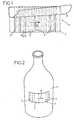
- the magnetically coded label 1can be fixed by gluing to a product, an article or an object, such as a bottle 7 as illustrated in FIG. figure 2 .
- the displacement of a suitable detector (not shown) in a direction F transversal son 5 and 6,can "read" the binary code formed by these son.
- the flexibility of the magnetically coded label 1allows its winding around the barrel of the bottle 7.
- the magnetically encoded label 1 or other marking according to the inventionmay also maintain a planar configuration, in particular in correspondence with a planar face of an object 8 to be identified or authenticated.
- the marking 1 with wires 5, 6 with ferromagnetic propertiescan be embedded in a support 2, itself incorporated into the object 8, the wires 5, 6 to be however drowned to shallow depth, so as to always allow their individual detection and the "reading" of the code formed by all of these son.
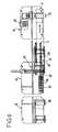
- the figure 4illustrates the continuous manufacturing process of an encoded adhesive complex, serving as a basis for the production of magnetically coded labels such as that shown in FIG. figure 1 .
- the starting point of the processis a coil 9 of virgin adhesive complex, consisting of a support sheet 2 having an adhesive-coated face, and a protective sheet 3 initially applied to the adhesive side of the support sheet 2.
- the coil 9is unwound (arrow F1), and the adhesive complex that constitutes it is delaminated, that is to say that the adhesive-coated backing sheet 2 is separated from the protective sheet 3.
- the two sheets 2 and 3then move forward. along distinct paths (arrows F2 and F3), being properly guided.
- the wires 5 with ferromagnetic properties, originating from respective wire coils,are laid down. of these son 5 being symbolized at 11.
- the son 5are thus placed parallel to each other, in the longitudinal direction of scroll F2 of the support sheet 2, and with a very precise transverse positioning, corresponding to the code retained for marking to achieve.
- the reconstituted adhesive complexis rewound, as indicated by the arrow F4, to form a new coil 12.
- the lattermay later be used for the printing of the complex and for its separation into individual markings, such as the label shown. on the figure 1 .
- the machinecomprises, above an elongated frame 13 and upstream downstream: a subassembly 14 unwinding and delamination, a module 15 for removing the son, and a subset 16 for re-rolling and rewinding.
- the upstream subassembly 14itself comprises a horizontal support shaft 17, for a coil 9 of virgin adhesive complex, to unwind according to the arrow F1. By leaving the coil 9, this adhesive complex separates into the support sheet 2, directed horizontally, and the protective sheet 3, directed first vertically.
- the protective sheet 3passes on a tensioning device 18, placed in the upper part of the upstream subassembly 14.
- This subassembly 14further comprises pairs of plates 19 and 20, used to facilitate the connection of the sheets 2 and 3 when changing the coil 9.
- the downstream subassembly 16comprises various rollers 27 28 and 29 of horizontal axes, which guide the two sheets 2 and 3 so as to bring them together.
- This downstream subassembly 16also comprises a horizontal support shaft 24, receiving a coil 12 on which is rewound the reconstituted and encoded adhesive complex.
- the support shaft 24is coupled to an electric motor 25, which is provided to drive the support shaft 24, so the coil 12, in continuous rotation.
- the downstream subassembly 16further comprises a detector 26 for the presence and correct positioning of the laid wires.
- the cassette 30is carried by a carriage 33, itself movable in transverse direction.
- the subassembly 31comprises a jack 34, oriented longitudinally, the upstream-facing rod carries hooking members of the ends of the wires 5. This subassembly 31 is itself transversely displaceable, by means of another cylinder 36.
- the device 32comprises a comb 37, whose different teeth are movable transversely.
- a jack 38is provided to control the raising and lowering of the comb 37.
- the detector 26constantly monitors the presence and the correct positioning of the laid wires, and it can in particular control the stopping of the machine in case of "breakage" of a wire 5, or of misreading .
- the figure 12shows a variant of the machine described above, the subsets and elements corresponding to those already described being designated by the marks.
- an interposed module 39which is designed according to the same principle as the module 15 but arranged for the laying a single wire 5, from a single coil 40.
- the additional module 39allows, in case of finding the absence of a wire, to put a replacement wire 5 on the support sheet 2, in the exact position of the missing wire.
- the inventionis not limited to the embodiments described above, by way of examples; it embraces, on the contrary, all the variants of implementation and application, regardless of the number of son, or the nature of their support, or the constructive details of the machines.
- at least one non-detectable yarnfor example non-magnetic, constituting a "decoy”.
- the inserted additional modulescan be multiplied, to allow the replacement of two or more broken wires.
Landscapes
- Physics & Mathematics (AREA)
- General Physics & Mathematics (AREA)
- Engineering & Computer Science (AREA)
- Theoretical Computer Science (AREA)
- Credit Cards Or The Like (AREA)
- Manufacturing Of Magnetic Record Carriers (AREA)
- Multi-Process Working Machines And Systems (AREA)
- General Factory Administration (AREA)
- Burglar Alarm Systems (AREA)
- Control Of Position, Course, Altitude, Or Attitude Of Moving Bodies (AREA)
- Electronic Switches (AREA)
Abstract
Description
Translated fromFrenchLa présente invention concerne de façon générale, le marquage d'articles, de produits ou d'objets, en vue de leur identification et/ou de leur authentification. Cette invention se rapporte, plus particulièrement, à un système de marquage sécurisé, par "étiquette magnétiquement codée" ou analogue pouvant être "lue" à l'aide d'un détecteur approprié. Le système de marquage selon l'invention possède des applications diverses :
- Protection contre la contrefaçon de produits industriels, par authentification des produits originaux ;
- Traçabilité de produits ou d'articles, par lot ou série de produits, ou éventuellement par article individuel ;
- Identification de produits ou d'articles, dans les circuits commerciaux, en complément ou éventuellement en remplacement du code-barre optique traditionnel.
- Protection against counterfeiting of industrial products, by authenticating the original products;
- Traceability of products or articles, by batch or series of products, or possibly by individual article;
- Identification of products or articles in commercial channels, in addition to or possibly replacing the traditional optical barcode.
L'identification d'articles et de produits par code-barre optique est actuellement bien connue, mais elle comporte des inconvénients. En particulier, un code-barre optique peut être facilement reproduit à l'aide d'un scanner ou d'un photocopieur du commerce, ou modifié, de sorte qu'il n'offre aucune véritable sécurité. De plus, le caractère nécessairement visible d'un code-barre optique peut entraîner des inconvénients d'ordre esthétique, pour certains genres d'objets ou articles.The identification of articles and products by optical barcode is currently well known, but it has drawbacks. In particular, an optical barcode can be easily reproduced by means of a commercial scanner or photocopier, or modified, so that it offers no real security. In addition, the necessarily visible nature of an optical barcode can cause aesthetic disadvantages for certain kinds of objects or articles.
Des systèmes de marquage par étiquettes magnétiques ont été déjà envisagés, même si actuellement ceux-ci sont peu diffusés. A titre d'exemples, on peut ici citer les propositions contenues dans les documents
- Utilisation de bandes magnétisées parallèles plus ou moins larges, donc trop facilement visibles (non transparentes) ;
- Utilisation de fils de longueur variables, combinés à des aimants, d'où une réalisation complexe ;
- Combinaison de fils à caractéristiques magnétiques différenciées ;
- Simple association de fils aimantés tous équidistants, interdisant de ce fait toute possibilité de codage.
- Use of parallel magnetic strips more or less wide, so too easily visible (non-transparent);
- Use of son of variable length, combined with magnets, resulting in a complex realization;
- Combination of yarns with differentiated magnetic characteristics;
- Simple combination of magnetic yarns all equidistant, thus prohibiting any possibility of coding.
La plupart des solutions déjà proposées restent donc assez complexes, donc coûteuses, en faisant notamment appel à des phénomènes magnétiques complexes et mal maîtrisés, sans qu'il en résulte une sécurité améliorée. En particulier, pour certains systèmes qui exploitent la longueur de fils ou bandes à propriétés magnétiques, une interruption de ces fils ou bandes peut provoquer une modification de la réponse du système. Par ailleurs, les systèmes connus n'offrent qu'un nombre limité de combinaisons pour réaliser un véritable codage, analogue à un code-barre traditionnel, ou bien ils n'y parviennent qu'au prix d'une complication excessive, tant au niveau de l'étiquette elle-même qu'au niveau du détecteur à utiliser pour "lire" cette étiquette.Most of the solutions already proposed therefore remain quite complex and therefore expensive, especially by using complex and poorly controlled magnetic phenomena, without resulting in a safety improved. In particular, for some systems that exploit the length of wires or tapes with magnetic properties, an interruption of these wires or tapes can cause a change in the response of the system. Furthermore, the known systems offer only a limited number of combinations to achieve a true coding, analogous to a traditional barcode, or they achieve it only at the cost of an excessive complication, both at the the label itself at the detector to be used to "read" this label.
Par le document
La présente invention vise à remédier à l'ensemble de ces inconvénients, en fournissant un système de marquage magnétique qui, tout en étant particulièrement simple et discret, s'avère extrêmement fiable et permet un codage avec des combinaisons très nombreuses.The present invention aims to remedy all of these disadvantages, by providing a magnetic marking system which, while being particularly simple and discreet, is extremely reliable and allows coding with very numerous combinations.
A cet effet, l'invention a essentiellement pour objet un marquage magnétique, qui comprend, posés sur ou dans un support, des fils parallèles à propriétés ferromagnétiques ultradouces, en particulier des filaments ferromagnétiques amorphes gainés de verre et réalisés dans un alliage magnétique amorphe composé de cobalt ou de fer, de nickel, de bore, de silicium et de carbone, l'âme métallique des filaments possédant un diamètre de l'ordre d'une dizaine à quelques dizaines de microns, l'épaisseur de la gaine de verre ne dépassant pas quelques microns, et le diamètre total des filaments ne dépassant pas 50 microns, ces fils étant disposés de manière à former un code binaire détectable, caractérisé en ce que les fils comprennent un premier fil pour le repérage du début d'une zone de lecture, dans laquelle sont positionnés le ou les fils définissant le code binaire, fils qui est ou sont posés dans des positions parallèles préétablie séparées par un intervalle constant selon une trame préétablie, les fils présents ou absents définissant le code binaire.For this purpose, the subject of the invention is essentially a magnetic marking, which comprises, placed on or in a support, parallel wires with ultra-fast ferromagnetic properties, in particular amorphous ferromagnetic filaments sheathed in glass and made of a composite amorphous magnetic alloy. cobalt or iron, nickel, boron, silicon and carbon, the metal core of the filaments having a diameter of the order of ten to a few tens of microns, the thickness of the glass sheath does not not exceeding a few microns, and the total diameter of the filaments not exceeding 50 microns, these wires being arranged to form a detectable binary code, characterized in that the wires comprise a first wire for locating the beginning of a zone of reading, in which are positioned the son or son defining the binary code, son who is or are placed in pre-established parallel positions separated by a constant tervalle according to a pre-established frame, the present or absent son defining the binary code.
Dans une forme de réalisation de l'invention, le support est du type bidimensionnel et constitué par une feuille de matière adhésive, qui fixe les fils à propriétés ferromagnétiques ultra-douces dans leurs positions préétablies. Cette feuille-support adhésive est avantageusement recouverte, au moins dans son état initial, par une feuille protectrice, du genre papier siliconé, qui ainsi recouvre aussi les fils.In one embodiment of the invention, the support is of the two-dimensional type and consists of a sheet of adhesive material, which fixes the son ultra-soft ferromagnetic properties in their pre-established positions. This adhesive support sheet is advantageously covered, at least in its initial state, by a protective sheet of the silicone paper type, which thus also covers the son.
En variante, le support est de type tridimensionnel, auquel cas les fils à propriétés ferromagnétiques sont noyés dans l'épaisseur de ce support à une profondeur faible, en comparaison à la distance de deux fils voisins, pour permettre dans tous les cas une détection par contact ou par quasi-contact, à l'aide d'un détecteur électro-magnétique se déplaçant sur la surface.In a variant, the support is of the three-dimensional type, in which case the wires with ferromagnetic properties are embedded in the thickness of this support at a small depth, in comparison with the distance of two adjacent wires, in order to allow detection in all cases. contact or quasi-contact, using an electromagnetic detector moving on the surface.
Les fils utilisés pour la réalisation d'un tel marquage sont, de préférence, des filaments ferromagnétiques amorphes gainés de verre, dont le mode de fabrication est expliqué dans : "
Le diamètre de l'âme métallique de tels filaments est de l'ordre d'une dizaine à quelques dizaines de microns, alors que l'épaisseur de la gaine de verre ne dépasse pas quelques microns, de sorte que le diamètre total des filaments ne dépasse pas 50 microns, et que les filaments peuvent être noyés dans la masse adhésive du support. L'âme métallique de ces filaments est réalisée dans un alliage magnétique amorphe essentiellement composé de cobalt ou de fer, de nickel, de bore, de silicium et de carbone, dans des proportions variables pouvant être :
- Fe ou Co > 40%,
- 0 < Ni < 20 %,
- 18 % < Si + B + C < 35 %
- Fe or Co> 40%,
- 0 <Ni <20%,
- 18% <Si + B + C <35%
De tels fils, de par leur structure amorphe, peuvent présenter selon leur composition un coefficient de magnétostriction positif ou négatif, et ils possèdent un champ magnétique à saturation (champ coercitif) relativement faible (de 50 à 500 A/m), ces propriétés étant variables en fonction de la composition de l'alliage ainsi que des proportions relatives d'alliage et de verre. Une description plus précise sur les propriétés magnétiques de ces fils peut être trouvée dans : "
En ce qui concerne le dispositif de détection, à utiliser pour "lire" les marquages, il s'agit avantageusement d'un dispositif portable, constitué d'une bobine d'excitation permettant de créer, dans l'espace ou voisinage immédiat du fil, un champ magnétique alternatif d'intensité supérieure au champ de saturation du fil à détecter, et de deux bobines de réception équilibrées, montées en opposition, de manière à ne détecter aucun signal de réponse en l'absence de fil situé à proximité, à l'intérieur de la zone volumique d'excitation. En revanche, lorsqu'un des fils ferromagnétiques d'un marquage est proche de la bobine d'excitation, celui-ci va subir l'influence de son champ magnétique et son aimantation induite va décrire un cycle d'hystérésis à la même fréquence que l'excitation. Le fil va alors réémettre un champ électro-magnétique de même fréquence qui sera détecté essentiellement par celle des deux bobines de réception située le plus proche du fil, grâce à une conception appropriée du détecteur. Par un traitement approprié du signal reçu ainsi sur le dispositif de détection, il est possible de déterminer la présence d'un fil à proximité du dispositif de détection. En conséquence, par déplacement de ce dispositif de détection portable, dans une direction transversale aux fils de marquage magnétique, il devient possible de "lire" instantanément le code binaire porté par ce marquage.With regard to the detection device, to be used for "reading" the markings, it is advantageously a portable device, consisting of an excitation coil for creating, in the space or immediate vicinity of the wire , an alternating magnetic field of intensity greater than the saturation field of the wire to be detected, and two balanced reception coils, mounted in opposition, so as to detect no response signal in the absence of a wire located in the vicinity, inside the excitation volume zone. On the other hand, when one of the ferromagnetic wires of a marking is close to the excitation coil, the latter will undergo the influence of its magnetic field and its induced magnetization will describe a hysteresis cycle at the same frequency as excitation. The wire will then re-emit an electromagnetic field of the same frequency which will be detected essentially by that of the two reception coils located closest to the wire, thanks to a suitable design of the detector. By appropriate treatment of the received signal thus on the detection device, it is possible to determine the presence of a wire near the detection device. Consequently, by moving this portable detection device in a direction transverse to the magnetic marking wires, it becomes possible to "read" instantly the binary code carried by this marking.
Ainsi, l'idée à la base de l'invention consiste en l'utilisation de fils ferromagnétiques de nature identique, possédant tous les mêmes propriétés magnétiques ultra-douces permettant leur détection à l'aide d'une excitation électromagnétique de proximité, et de faible puissance (cette détection étant indépendante de la longueur des fils), ces fils étant positionnés de manière précise sur ou dans un support, à la manière d'un code-barre. Le système de marquage ainsi constitué comporte, en comparaison avec toutes les solutions précédemment proposées, des avantages nombreux et importants :
- Les fils utilisés pouvant posséder un diamètre très réduit, compris entre dix et cinquante microns, le système reste invisible à l'oeil nu, et aussi imperceptible au toucher. Ceci permet de placer les fils sur une feuille-support transparente, par exemple en matière plastique transparente, l'ensemble pouvant être placé sur d'autres étiquettes normales en restant invisible.
- Les possibilités de codage sont presque illimitées, compte tenu du très grand nombre de combinaisons possibles du nombre de fils et du positionnement relatif de ces fils.
- Les principes de codage et de détection ne font appel ni à une différenciation des propriétés magnétiques des fils, ni à un choix de leur longueur, dès lors que cette longueur est supérieure à une valeur minimum, de l'ordre de 5 millimètres. Le système reste donc particulièrement simple, tant en ce qui concerne la structure du marquage lui-même, que pour ce qui est de la détection.
- Tous les fils parallèles étant identiques (en diamètre, longueur, composition, propriétés magnétiques, coercivité), on évite le risque d'erreurs lors de la manipulation des bobines de fils, pour la fabrication des marquages magnétiques.
- Dans la mesure où la longueur des fils n'exerce pas d'influence, une interruption de ces fils (par exemple par un coup de "cutter") ne saurait neutraliser le système, qui continue de fournir alors une réponse bien identifiée.
- Les fils ferromagnétiques peuvent être noyés dans toute matière moulée ou façonnée, ou être inclus dans un support textile, ce qui rend le marquage encore plus discret, et incorporable directement dans un produit ou objet.
- La souplesse des fils, et le cas échéant de leur support, autorise toute configuration d'étiquette, notamment pour former une étiquette magnétiquement codée à appliquer sur une surface cylindrique, telle que le fût d'une bouteille.
- Les propriétés magnétiques ici exploitées des fils sont très peu sensibles aux variations de température, dans une large plage (de -50° C à + 80° C par exemple), contrairement aux circuits magnétiques résonants de type LC sérigraphiés sur des étiquettes magnétiques interrogeables en haute fréquence, dans lesquels la capacité, donc la fréquence de résonance, varie sensiblement avec la température, compte tenu de la variation thermique de la permittivité du délectrique utilisé.
- Les fils étant constitués en un alliage magnétique amorphe ultra-doux, ceux-ci possèdent une faible coercivité qui permet de faire appel à des têtes de détecteurs de proximité de très faible champ rayonné, donc à très faible consommation de puissance, ce qui augmente l'autonomie des détecteurs portables.
- La détection de présence ou d'absence des fils, intervenant comme des antennes secondaires, s'effectue par une analyse des harmoniques générés par ces fils lors de leur approche de la saturation magnétique. Ainsi,la disposition géométrique des fils parallèles, et le codage qu'elle autorise, se prêtent bien à une analyse de la réponse par traitement du signal, avec mise en oeuvre de logiciels de traitement pouvant tolérer un certain degré d'erreur dans la calibration des écartements entre fils, ce qui facilite grandement la conception des machines réalisant la pose des fils.
- Le codage étant basé sur des fils à propriétés magnétiques douces, il ne peut être détruit, altéré ou effacé par un champ magnétique parasite, créé volontairement ou fortuitement, et de forte intensité, ceci contrairement à beaucoup de systèmes de codage magnétique existants basés sur des éléments magnétiquement "durs", tels que les cartes bancaires, les cartes à bande magnétique, ou les étiquettes à deux couches magnétiques (l'une dure et l'autre douce).
- Le faible diamètre des fils interdit sa détection par les antennes de surveillance électronique d'articles (dites antennes EAS).
- La réponse de chaque fil est indépendante de l'intensité du champ d'excitation délivré par le détecteur (à condition d'avoir la valeur d'intensité minimale pour saturer les fils), et cette réponse est donc toujours la même, ce qui facilite l'ajustement de l'intensité de la bobine d'excitation.
- Le principe de fils parallèles permet une fabrication aisée des marquages magnétiques en question, en continu ou en semi-continu, avec tronçonnage à la longueur désirée.
- The used son can have a very small diameter, between ten and fifty microns, the system is invisible to the naked eye, and also imperceptible to the touch. This allows the son to be placed on a transparent support sheet, for example transparent plastic material, the assembly can be placed on other normal labels while remaining invisible.
- The coding possibilities are almost unlimited, given the very large number of possible combinations of the number of wires and the relative positioning of these wires.
- The principles of coding and detection do not call for a differentiation of the magnetic properties of the wires, nor for a choice of their length, since this length is greater than a minimum value, of the order of 5 millimeters. The system therefore remains particularly simple, both as regards the structure of the marking itself, as for the detection.
- Since all the parallel wires are identical (in diameter, length, composition, magnetic properties, coercivity), the risk of errors in handling the wire coils for the manufacture of the magnetic markings is avoided.
- Insofar as the length of the wires does not exert an influence, an interruption of these wires (for example by a blow of "cutter") can not neutralize the system, which continues to provide then a well identified answer.
- The ferromagnetic wires may be embedded in any molded or shaped material, or be included in a textile support, which makes the marking even more discreet, and directly incorporated into a product or object.
- The flexibility of the yarns, and where appropriate their support, allows any label configuration, in particular to form a magnetically coded label to be applied to a cylindrical surface, such as the barrel of a bottle.
- The magnetic properties exploited here by the wires are very insensitive to temperature variations, in a wide range (from -50 ° C. to + 80 ° C., for example), unlike resonant circuits of the LC type screen printed on magnetic labels interrogable in high frequency, in which the capacitance, therefore the resonant frequency, varies substantially with the temperature, taking into account the thermal variation of the permittivity of the electrical used.
- Since the wires are made of an ultra-soft amorphous magnetic alloy, they have a low coercivity which makes it possible to use proximity sensor heads of very low radiated field, and therefore with very low power consumption, which increases autonomy of portable detectors.
- Detecting the presence or absence of the son, acting as secondary antennas, is performed by an analysis of the harmonics generated by these son as they approach the magnetic saturation. Thus, the geometrical arrangement of the parallel wires, and the coding that it allows, lend themselves well to an analysis of the response by signal processing, with the implementation of processing software that can tolerate a certain degree of error in the calibration. spacings between son, which greatly facilitates the design of machines performing the laying of son.
- Since the coding is based on wires with soft magnetic properties, it can not be destroyed, altered or erased by a parasitic magnetic field, created voluntarily or fortuitously, and of high intensity, unlike many existing magnetic coding systems based on items magnetically "hard", such as bank cards, magnetic stripe cards, or two-layer magnetic labels (one hard and the other soft).
- The small diameter of the wires prohibits its detection by the antennas of electronic surveillance of articles (so-called antennas EAS).
- The response of each wire is independent of the intensity of the excitation field delivered by the detector (provided to have the minimum intensity value to saturate the son), and this response is therefore always the same, which facilitates adjusting the intensity of the excitation coil.
- The principle of parallel son allows easy manufacture of the magnetic markings in question, continuous or semi-continuous, with cutting to the desired length.
Dans la zone de lecture, l'espacement entre les positions possibles de fils est de préférence égal au minimum à 2 millimètres, un tel "pas" minimum étant nécessaire pour distinguer les fils lors de la détection, en évitant que plusieurs fils puissent se trouver simultanément à l'intérieur de la zone d'intensité critique d'excitation, ou que ces fils aient une influence les uns sur les autres. Le "pas" est choisi en fonction des dimensions des étiquettes et du nombre de fils, ce "pas" pouvant atteindre plusieurs millimètres. La largeur utile des étiquettes (dimension transversale aux fils) peut être comprise entre quelques millimètres et plusieurs centimètres, une telle dimension autorisant l'utilisation d'un code binaire à plusieurs dizaines de bits, offrant ainsi de nombreuses combinaisons.In the reading zone, the spacing between the possible wire positions is preferably at least 2 millimeters, such a minimum "step" being necessary to distinguish the wires during the detection, avoiding that several wires can be found. simultaneously within the excitation critical intensity zone, or that these wires have an influence on one another. The "step" is chosen according to the dimensions of the labels and the number of wires, this "step" being able to reach several millimeters. The useful width of the labels (transverse dimension son) can be between a few millimeters and several centimeters, such a size allowing the use of a binary code to several tens of bits, thus offering many combinations.
Dans la conception la plus simple du codage, l'absence de fil dans une position donnée correspond à la valeur ZERO, et la présence d'un fil dans la position considérée correspond à la valeur UN.In the simplest design of the coding, the absence of wire in a given position corresponds to the value ZERO, and the presence of a wire in the considered position corresponds to the value UN.
L'invention a aussi pour objet un procédé industriel pour la fabrication du marquage magnétique précédemment défini, dans le cas où ce marquage est constitué par une feuille-support en matière adhésive, qui fixe les fils à propriétés ferromagnétiques dans leurs positions préétablies, cette feuille-support étant à recouvrir par une feuille protectrice.The subject of the invention is also an industrial process for the manufacture of the previously defined magnetic marking, in the case where this marking consists of a support sheet of adhesive material, which fixes the son with ferromagnetic properties in their pre-established positions, this support sheet being covered by a protective sheet.
Ce procédé consiste, essentiellement, à dérouler une bobine de complexe adhésif vierge, constitué d'une feuille-support en matière adhésivée et d'une feuille protectrice, recouvrant initialement la face adhésivée, à effectuer une opération de délaminage de ce complexe adhésif, consistant à séparer la feuille-support adhésivée de la feuille protectrice, tout en faisant avancer ces deux feuilles, à déposer des fils à propriétés ferromagnétiques ultra-douces sur la feuille-support adhésivée, dans le sens longitudinal de défilement de cette feuille, en positionnant transversalement les fils de manière précise en correspondance avec le code retenu pour le marquage, puis à effectuer une opération de relaminage, consistant à ramener la feuille protectrice sur la feuille-support adhésivée, désormais garnie des fils, et enfin à réenrouler le complexe adhésif reconstitué et incorporant les fils. On obtient ainsi une bobine de complexe adhésif, incorporant les fils à propriétés ferromagnétiques, répartis de la manière désirée. La bobine finalement obtenue peut alors être utilisée comme n'importe quelle autre bobine de complexe adhésif destinée à des opérations d'impression et de découpe, pour l'obtention de supports adhésifs séparés qui, dans le cas présent, seront par exemple des étiquettes magnétiquement codées avec fils incorporés, ou des produits façonnés au format de feuilles quelconques.The method essentially consists in unrolling a virgin adhesive complex coil, consisting of a carrier sheet of adhesive material and a protective sheet, initially covering the adhesive-coated face, to perform a delamination operation of this adhesive complex, consisting of separating the adhesive-coated backing sheet from the protective sheet, while advancing these two sheets, to deposit son with ultra-soft ferromagnetic properties on the adhesive-coated backing sheet, in the longitudinal direction of travel of this sheet, by positioning transversely the yarns accurately in correspondence with the code retained for the marking, then to perform a re-rolling operation, of bringing the protective sheet back onto the adhesive-coated backing sheet, now lined with the yarns, and finally to rewind the reconstituted adhesive complex and incorporating the wires. A coil of adhesive complex is thus obtained, incorporating the wires with ferromagnetic properties, distributed in the desired manner. The reel finally obtained can then be used like any other adhesive complex coil for printing and cutting operations, to obtain separate adhesive media which, in this case, will be, for example, labels magnetically. encoded with embedded threads, or shaped products in any sheet format.
Enfin, l'invention a pour objet une machine spécialement destinée à la mise en oeuvre du procédé défini ci-dessus, donc une machine pour la fabrication du marquage magnétique, toujours dans le cas où celui-ci est constitué par une feuille-support en matière adhésivée, qui fixe les fils à propriétés ferromagnétiques dans leurs positions préétablies, cette feuille-support étant recouverte d'une feuille protectrice.Finally, the subject of the invention is a machine specially designed for implementing the method defined above, and therefore a machine for manufacturing the magnetic marking, again in the case where it is constituted by a support sheet in adhesive material, which sets the son ferromagnetic properties in their pre-established positions, this sheet-support being covered with a protective sheet.
La machine en question comprend essentiellement, en combinaison et d'amont en aval :
- des moyens de support et de déroulage d'une bobine de complexe adhésif vierge, constitué d'une feuille-support en matière adhésivée et d'une feuille protectrice recouvrant initialement la face adhésivée ;
- des moyens de délaminage, assurant la séparation de la feuille-support adhésivée et de la feuille protectrice ;
- des moyens d'amenée et de dépose de fils à propriétés ferromagnétiques ultra-douces sur la feuille adhésivée, incluant des moyens pour le positionnement transversal de ces fils en correspondance avec le code retenu pour le marquage ;
- des moyens de relaminage, assurant la réunion de la feuille protectrice et de la feuille-support en matière adhésivée, garnie des fils ; et
- des moyens d'entraînement et d'enroulement du complexe adhésif reconstitué et incorporant les fils.
- means for supporting and unwinding a virgin adhesive complex coil consisting of a carrier sheet of adhesive material and a protective sheet initially covering the adhesive side;
- delamination means, ensuring the separation of the adhesive-coated sheet and the protective sheet;
- means for supplying and removing yarns with ultra-soft ferromagnetic properties on the adhesive-coated sheet, including means for the transverse positioning of these yarns in correspondence with the code selected for the marking;
- relining means, ensuring the joining of the protective sheet and the support sheet of adhesive material, packed son; and
- means for driving and winding the adhesive complex reconstituted and incorporating the son.
Avantageusement, les moyens d'amenée et de dépose de fils à propriétés ferromagnétiques comprennent, eux-mêmes :
- un support mobile verticalement, pour une pluralité de bobines de fil à propriétés ferromagnétiques ;
- des moyens pour l'accrochage initial et la traction des extrémités des fils issus de ces bobines ; et
- entre lesdites bobines de fil et ces moyens d'accrochage et de traction, un dispositif de positionnement transversal des fils.
- a vertically movable support for a plurality of wire coils with ferromagnetic properties;
- means for the initial attachment and traction of the ends of the son from these coils; and
- between said wire coils and these attachment and traction means, a transverse positioning device son.
Ainsi, la machine est équipée pour initier le processus de dépose des fils, par accrochage et traction des extrémités de ces fils, le support des bobines étant alors placé en position haute pour éviter un collage intempestif des fils sur la surface adhésivée, spécialement lors du positionnement transversal de ces fils pour réaliser le code souhaité. Ensuite, le support des bobines est abaissé, de sorte que les fils viennent tangenter la matière adhésive, et commencent à se fixer sur celle-ci. On notera qu'une fois fixés, les fils sont entraînés en avant avec la feuille-support, ce qui rend superflus tous moyens spécifiques de déroulage des bobines de fils ou de traction des fils.Thus, the machine is equipped to initiate the process of removing the son, by hooking and pulling the ends of these son, the support of the coils then being placed in the upper position to prevent inadvertent bonding of the son on the adhesive surface, especially during the transverse positioning of these wires to achieve the desired code. Then, the support of the coils is lowered, so that the son come tangent the adhesive material, and begin to attach to it. Note that once fixed, the son are driven forward with the support sheet, which makes superfluous any specific means of unwinding wire coils or traction son.
De préférence, la machine est encore équipée, dans sa partie aval, de moyens de contrôle de la présence et du positionnement correct des fils posés, ces moyens pouvant intervenir en "lisant" le code formé par les fils, ceci d'une manière analogue à la "lecture" du même code par un dispositif de détection.Preferably, the machine is further equipped, in its downstream part, with means for checking the presence and correct positioning of the laid wires, these means being able to intervene by "reading" the code formed by the wires, this in a similar way the "reading" of the same code by a detection device.
Dans le cas le plus simple, si ces derniers moyens constatent l'absence anormale d'un fil, généralement causée par la "casse" de ce fil, la machine doit être arrêtée en vue d'une remise en état manuelle.In the simplest case, if the latter means detect the abnormal absence of a wire, usually caused by the "breakage" of the wire, the machine must be stopped for manual reconditioning.
Toutefois, dans une forme de réalisation perfectionnée de la machine, celle-ci comprend encore, intercalé entre les moyens précités d'amenée et de dépose des fils et les moyens de relaminage, au moins un module additionnel de pose d'un fil, ce qui permet de pallier automatiquement, et de façon quasi-instantanée, à la "casse" d'un fil, constatée par les moyens de contrôle de la présence et du positionnement correct des fils. Au cas où plusieurs modules analogues seraient ainsi successivement intercalés, la machine pourrait même pallier automatiquement à la "casse" de deux ou plusieurs fils. Avantageusement, cette machine est également équipée d'un dispositif de marquage, permettant de repérer la zone défectueuse, pour l'utilisation pratique ultérieure de la bobine.However, in an improved embodiment of the machine, it still comprises, interposed between the aforementioned means supply and removal of the son and the re-rolling means, at least one additional module for laying a wire, which makes it possible to automatically and almost instantaneously overcome the "breakage" of a wire, found by the means of control of the presence and correct positioning of the son. If several analogous modules are thus successively interposed, the machine could even automatically overcome the "breakage" of two or more son. Advantageously, this machine is also equipped with a marking device, to identify the defective area, for subsequent practical use of the coil.
Comme on le comprend aisément, le procédé et la machine, précédemment définis, permettent la fabrication automatique en continu, à cadence élevée et de manière fiable, de "matière première" codée permettant l'impression et la découpe d'un complexe adhésif en vue de l'obtention de marquages conformes à l'invention, tout en permettant de varier les codes de ces marquages par le positionnement transversal des fils.As is readily understood, the method and the machine, as previously defined, allow the automatic, high-speed, reliable production of coded "raw material" for printing and cutting an adhesive complex for obtaining markings according to the invention, while allowing to vary the codes of these markings by the transverse positioning of the son.
De toute façon, l'invention sera mieux comprise à l'aide de la description qui suit, en référence au dessin schématique annexé qui représente, à titre d'exemples, diverses formes de réalisation et utilisations de ce système de marquage magnétique, qui illustre aussi le procédé de fabrication selon l'invention, et qui enfin montre des formes d'exécution de la machine pour la mise en oeuvre de ce procédé :
Figure 1 est une vue de face d'une étiquette magnétiquement codée conforme à l'invention ;Figure 2 illustre une utilisation de cette étiquette magnétiquement codée ;Figure 3 représente un autre marquage conforme à l'invention, en illustrant son utilisation ;Figure 4 est un schéma illustrant le procédé de fabrication de supports adhésifs magnétiquement codés selon l'invention ;Figure 5 est une vue de côté d'une machine de mise en oeuvre de ce procédé ;Figure 6 est une vue en plan par dessus de la machine defigure 5 ;Figures 7, 8 ,9 et 10 sont des schémas partiels de cette machine, en vue de côté, illustrant des phases successives de son fonctionnement ;Figure 11 est un autre schéma partiel de la même machine, en vue en plan par-dessus;Figure 12 est une vue de côté d'une variante de cette machine.
Figure 1 is a front view of a magnetically encoded label according to the invention;Figure 2 illustrates a use of this magnetically encoded tag;Figure 3 represents another marking according to the invention, illustrating its use;Figure 4 is a diagram illustrating the method of manufacturing magnetically encoded adhesive media according to the invention;Figure 5 is a side view of a machine for carrying out this method;Figure 6 is a plan view over the machine offigure 5 ;Figures 7, 8 ,9 and 10 are partial diagrams of this machine, in side view, illustrating successive phases of its operation;Figure 11 is another partial diagram of the same machine, in plan view over it;Figure 12 is a side view of a variant of this machine.
La
Sur l'étiquette magnétiquement codée 1 sont pré-définies des positions parallèles 4, séparés par un écartement ou "pas" constant "e". Dans certaines de ces positions 4 préétablies sont posés des fils parallèles 5 à propriétés ferromagnétiques ultra-douces. L'absence ou la présence des fils 5, dans les différentes positions 4 possibles, définit un code binaire détectable, propre à chaque étiquette 1.On the magnetically encoded
Le marquage comprend encore avantageusement, vers une extrémité de l'étiquette 1, un premier fil 6 à propriétés ferromagnétiques, permettant le repérage du début de la "zone de lecture" dans laquelle sont positionnés les autres fils 5.The marking advantageously further comprises, towards one end of the
Tous les fils 5 et 6 sont fixés, dans leurs positions préétablies, par simple adhésion sur la face adhésivée de la feuille-support 2. La feuille de protection 3 recouvre initialement ces fils 5 et 6.All the
Après retrait de la feuille de protection 3, l'étiquette magnétiquement codée 1 peut être fixée par collage sur un produit, un article ou un objet, tel qu'une bouteille 7 comme illustré sur la
Dans l'exemple d'utilisation de la
En se référant toujours à la
La
Le point de départ du procédé est une bobine 9 de complexe adhésif vierge, constitué d'une feuille-support 2 possédant une face adhésivée, et d'une feuille de protection 3 initialement appliqué sur la face adhésivée de la feuille support 2.The starting point of the process is a coil 9 of virgin adhesive complex, consisting of a
La bobine 9 est déroulée (flèche F1), et le complexe adhésif qui le constitue est délaminé, c'est-à-dire que la feuille-support adhésivée 2 est séparée de la feuille protectrice 3. Les deux feuilles 2 et 3 avancent alors selon des trajets distincts (flèches F2 et F3), en étant convenablement guidées.The coil 9 is unwound (arrow F1), and the adhesive complex that constitutes it is delaminated, that is to say that the adhesive-coated
Sur le trajet de la feuille-support adhésivée 2, qui se situe au-dessous du trajet de la feuille protectrice 3, il est procédé à la pose des fils 5 à propriétés ferromagnétiques, issus de bobines de fil 10 respectives, le dispositif de pose de ces fils 5 étant symbolisé en 11. Les fils 5 sont ainsi posés parallèlement les uns aux autres, dans la direction longitudinale de défilement F2 de la feuille-support 2, et avec un positionnement transversal bien précis, correspondant au code retenu pour le marquage à réaliser.In the path of the adhesive-coated
Ensuite, il est procédé au relaminage, c'est-à-dire que la feuille protectrice 3 est ramenée sur la feuille-support 2, désormais garnie de fils 5. La réunion de deux feuilles 2 et 3 "emprisonne" les fils 5 entre ces deux feuilles 2 et 3, et l'on obtient ainsi un complexe adhésif reconstitué, incorporant les fils 5.Then, it is proceeded to re-rolling, that is to say that the protective sheet 3 is returned to the
Enfin, le complexe adhésif reconstitué est réenroulé, comme indiqué par la flèche F4, pour former une nouvelle bobine 12. Cette dernière peut ultérieurement être reprise, pour l'impression du complexe et pour sa séparation en marquages individuels, tels que l'étiquette montrée sur la
Les
En se référant plus particulièrement aux
Le sous-ensemble amont 14 comporte lui-même un arbre-support horizontal 17, pour une bobine 9 de complexe adhésif vierge, à dérouler suivant la flèche F1. En quittant la bobine 9, ce complexe adhésif se sépare en la feuille-support 2, dirigée horizontalement, et la feuille de protection 3, dirigée d'abord verticalement. La feuille de protection 3 passe sur un dispositif de tension 18, placé dans la partie supérieure du sous-ensemble amont 14. Ce sous-ensemble 14 comprend encore des paires de plaques 19 et 20, utilisées pour faciliter le raccordement des feuilles 2 et 3 lors d'un changement de la bobine 9.The
Le sous-ensemble aval 16 comporte divers rouleaux 27 28 et 29 d'axes horizontaux, qui guident les deux feuilles 2 et 3 de manière à les réunir. Ce sous-ensemble aval 16 comporte aussi un arbre-support horizontal 24, recevant une bobine 12 sur laquelle est réenroulé le complexe adhésif reconstitué et codé. L'arbre-support 24 est accouplé à un moteur électrique 25, qui est prévu pour entraîner cet arbre-support 24, donc la bobine 12, en rotation continue. Entre les deux derniers rouleaux 28 et 29, le sous-ensemble aval 16 comporte encore un détecteur 26 de la présence et du positionnement correct des fils posés.The
Le module 15 de dépose des fils, intercalé entre le sous-ensemble amont 14 et le sous-ensemble aval 16, comprend lui-même :
- des rouleaux 21, 22 et 23 d'axes horizontaux, pour le guidage de la feuille-
support adhésivée 2 ; un support amovible 30, du genre "cassette", pour les bobines de fil 10,le support 30 étant monté mobile verticalement (flèche F5), au moyen d'un vérin ;- un sous-
ensemble 31 d'accrochage initial et de traction des fils 5 ; et - entre la "cassette" 30 et le sous-
ensemble 31, au-dessus des rouleaux 22et 23,un dispositif 32 de positionnement transversal desfils 5.
rollers backing sheet 2;- a
removable support 30, of the "cassette" type, for the bobbins ofthread 10, thesupport 30 being mounted vertically movable (arrow F5), by means of a jack; - a
subset 31 of initial attachment and traction of theson 5; and - between the "cassette" 30 and the
subassembly 31, above therollers device 32 for transverse positioning of thethreads 5.
La cassette 30 est portée par un chariot 33, lui-même mobile en direction transversale.The
Le sous-ensemble 31 comporte un vérin 34, orienté longitudinalement, dont la tige dirigée vers l'amont porte des organes 35 d'accrochage des extrémités des fils 5. Ce sous-ensemble 31 est lui-même déplaçable transversalement, au moyen d'un autre vérin 36.The
Enfin, le dispositif 32 comprend un peigne 37, dont les différentes dents sont déplaçables transversalement. Un vérin 38 est prévu pour commander la montée et la descente du peigne 37.Finally, the
Les
- Première phase (
figure 7 ) :- La "cassette" 30 étant en position haute, les extrémités des fils 5, issus des différentes bobines 10, sont accrochées sur les organes 35, approchés de la "cassette" 30 par sortie de la tige du vérin 34.
Le peigne 37 se trouve alors escamoté vers le haut.
- La "cassette" 30 étant en position haute, les extrémités des fils 5, issus des différentes bobines 10, sont accrochées sur les organes 35, approchés de la "cassette" 30 par sortie de la tige du vérin 34.
- Deuxième phase (
figure 8 ) :- Le vérin 34 est rétracté, en tirant alors en avant les fils 5, dont les portions déroulées sont maintenues au-dessus de la feuille-
support 2, afin d'éviter d'être au conctact avec la surface adhésive. A ce stade, les fils 5 restent équidistants.
- Le vérin 34 est rétracté, en tirant alors en avant les fils 5, dont les portions déroulées sont maintenues au-dessus de la feuille-
- Troisième phase (
figure 9 ) :Le peigne 37 est abaissé, par actionnement du vérin 38. Les dentsde ce peigne 37 s'intercalent alors entre les fils 5 et chaque dent pousse latéralement un fil, de manière à obtenir les positions et écartements souhaités de tous les fils 5.
- Quatrième phase (
figure 10 ) :- La "cassette" 30 est abaissée, de telle sorte que les fils 5, précédemment positionnés, entrent en contact avec la face adhésivée de la feuille-
support 2. La "cassette" 30 est alors réalignée avec la feuille-support 2, par déplacement transversal - voir aussi lafigure 11 (flèche F6).
- La "cassette" 30 est abaissée, de telle sorte que les fils 5, précédemment positionnés, entrent en contact avec la face adhésivée de la feuille-
- Cinquième phase (non illustrée) :
- On coupe les extrémités des fils 5, saisies précédemment par les organes 35, au moyen d'un dispositif automatique de coupe (non représenté).
- Sixième phase :
- Le moteur 25 est mis en marche, de manière à entraîner en rotation l'arbre-
support 24, donc à commencer à réenrouler le complexe adhésif codé sur la bobine 12 (flèche F4). Les deux feuilles 2 et 3 sont ainsi entraînées en avant, de façon synchronisée (flèches F2 et F3), la feuille-support adhésivée 2 entraînant avec elle les fils 5 déposés, en les déroulant de leurs bobines 10 respectives.
- Le moteur 25 est mis en marche, de manière à entraîner en rotation l'arbre-
- First phase (
figure 7 ):- The "cassette" 30 being in the high position, the ends of the
son 5, coming from thedifferent coils 10, are hooked on themembers 35, approaching the "cassette" 30 by output of the rod of thejack 34. Thecomb 37 is located then retracted up.
- The "cassette" 30 being in the high position, the ends of the
- Second phase (
figure 8 ):- The
cylinder 34 is retracted, then pulling forward theson 5, the unwrapped portions are held above thesupport sheet 2, to avoid being in contact with the adhesive surface. At this point, thewires 5 remain equidistant.
- The
- Third phase (
figure 9 ):- The
comb 37 is lowered by actuation of thecylinder 38. The teeth of thiscomb 37 are then interposed between thewires 5 and each tooth laterally pushes a wire, so as to obtain the desired positions and spacings of all thewires 5.
- The
- Fourth phase (
figure 10 ):- The "cassette" 30 is lowered, so that the previously positioned
threads 5 come into contact with the adhesive side of thebacking sheet 2. The "cassette" 30 is then realigned with thebacking sheet 2, by moving transversal - see alsofigure 11 (arrow F6).
- The "cassette" 30 is lowered, so that the previously positioned
- Fifth phase (not shown):
- The ends of the
wires 5, previously grasped by themembers 35, are cut off by means of an automatic cutting device (not shown).
- The ends of the
- Sixth phase:
- The
motor 25 is started, so as to rotate thesupport shaft 24, so to begin to rewind the adhesive complex coded on the coil 12 (arrow F4). The twosheets 2 and 3 are thus driven forward synchronously (arrows F2 and F3), the adhesive-coatedsheet 2 carrying with it theson 5 deposited by unwinding theirrespective coils 10.
- The
Au cours de ce processus, le détecteur 26 contrôle en permanence la présence et le positionnement correct des fils 5 posés, et il peut notamment commander l'arrêt de la machine en cas de "casse" d'un fil 5, ou de mauvaise lecture.During this process, the
La
Dans cette variante, entre le module 15 de dépose des fils 5 et le sous-ensemble aval 16 de relaminage et de réenroulement, il est encore prévu un module 39 intercalé, qui est conçu selon le même principe que le module 15 mais agencé pour la pose d'un seul fil 5, issu d'une unique bobine 40. En combinaison avec le détecteur 26, le module additionnel 39 permet, en cas de constatation de l'absence d'un fil, de poser un fil 5 de remplacement sur la feuille-support 2, dans la position exacte du fil manquant.In this variant, between the
Comme il va de soi, l'invention ne se limite pas aux seuls modes d'exécution décrits ci-dessus, à titre d'exemples ; elle en embrasse, au contraire, toutes les variantes de réalisation et d'application, quels que soient notamment le nombre des fils, ou la nature de leur support, ou encore les détails constructifs des machines. Ainsi, il est possible d'incorporer au marquage, selon le même procédé que les autres fils, au moins un fil non détectable, par exemple non magnétique, constituant un "leurre". Dans le même ordre d'idées, par référence à la variante de la
Claims (15)
- A magnetic marking system comprising, laid on or in a carrier (2), wires (5, 6) having ultrasoft ferromagnetic properties, in particular glass-clad ferromagnetic filaments made of an amorphous magnetic alloy composed of cobalt or of iron, of nickel, of boron, of silicon and of carbon, the metal core of the filaments (5) possessing a diameter of the order of some ten to a few tens of microns, the thickness of the glass cladding not exceeding a few microns, said wires being arranged so as to form a detectable binary code,characterized in that the wires comprise a first wire (6) for tagging the start of a reading zone, in which are positioned the wire or wires (5) defining the binary code, said wire or wires being laid in pre-established parallel positions (4) separated by a constant gap (e) according to a pre-established frame, the present or absent wires (5) defining the binary code.
- A magnetic marking system as claimed in claim 1,characterized in that the carrier is of the two-dimensional type and constituted by a sheet of adhesive-coated material (2), which fixes the wires (5) having ultrasoft ferromagnetic properties in their pre-established positions (4).
- The magnetic marking system as claimed in claim 2,characterized in that the adhesive-coated carrier sheet (2) is covered, at least in its initial state, with a protective sheet (3), of the silicone-coated paper kind, which thus also covers the wires (5).
- The magnetic marking system as claimed in claim 2 or 3,characterized in that the carrier sheet (2) is a transparent sheet.
- The magnetic marking system as claimed in claim 1,characterized in that the carrier is of the three-dimensional type, in which case the wires (5) having ferromagnetic properties are embedded in the thickness of this carrier, in their pre-established positions (4).
- The magnetic marking system as claimed in any one of claims 1 to 5,characterized in that in the reading zone, the spacing between the possible positions (4) of wires (5) is equal at the minimum to 2 millimeters.
- The magnetic marking system as claimed in any one of claims 1 to 6,characterized in that at least one nondetectable wire, for example a nonmagnetic wire, constituting a "decoy" is incorporated into the marking(1).
- A method for the production of a magnetic marking, more particularly of a marking (1) constituted by a carrier sheet (2) made of adhesive-coated material, which fixes wires (5) having ferromagnetic properties in their pre-established positions (4), this carrier sheet (2) having to be covered with a protective sheet (3),
characterized in that it consists in unwinding (F1) a coil (9) of virgin adhesive complex, which coil consists of a carrier sheet (2) made of adhesive-coated material and of a protective sheet (3) covering the adhesive-coated face, in performing an operation of relamination of this adhesive complex, consisting in separating the adhesive-coated carrier sheet (2) from the protective sheet (3), while advancing (F2, F3) these two sheets (2, 3), in depositing wires (5) having ultrasoft ferromagnetic properties on the adhesive-coated carrier sheet (2) in the longitudinal direction of travel (F2) of this sheet (2), while positioning the wires (5) transversely in a precise manner in correspondence with the code adopted for the marking (1), then in performing a relamination operation, consisting in returning the protective sheet (3) onto the adhesive-coated carrier sheet (2) henceforth furnished with the wires (5), and finally in rewinding (F4,12) the reconstituted adhesive complex incorporating the wires (5). - The method as claimed in claim 8,characterized in that the coil (12) finally obtained is subjected to printing and cutting operations, so as to obtain separate adhesive carriers, for example magnetically coded labels (1) with incorporated wires (5).
- A machine intended for the implementation of the method as claimed in claim 8 or 9, for the production of the magnetic marking (1) constituted by a carrier sheet (2) made of adhesive-coated material which fixes the wires (5) having ferromagnetic properties in their pre-established positions (4), this carrier sheet (2) being covered with a protective sheet (3),characterized in that it comprises, in combination (26) and from upstream to downstream:- means (14, 17) for carrying and unwinding a coil (9) of virgin adhesive complex, consisting of a carrier sheet (2) made of adhesive-coated material and of a protective sheet (3);- means (15) of bringing and depositing wires (5) having ultrasoft ferromagnetic properties onto the adhesive-coated sheet, including means (37, 38) for the transverse positioning of these wires (5) in correspondence with the code adopted for the marking (1) ;- means (16) of relamination, ensuring the rejoining of the protective sheet (3) and of the carrier sheet (2) made of adhesive-coated material, furnished with the wires (5); and- means (24, 25) of driving and winding up the reconstituted adhesive complex incorporating the wires (5).
- The machine as claimed in claim 10,characterized in that the means (15) of bringing and depositing wires (5) having magnetic properties comprise:- a vertically mobile carrier (30), for a plurality of coils (10) of wires (5) having ferromagnetic properties;- means (31) for the initial fastening and the pulling of the ends of the wires (5) emanating from these coils (10); and- between said coils (10) of wire (5) and these means of fastening and of pulling (31), a device (32) for transverse positioning of the wires (5).
- The machine as claimed in claim 11,characterized in that the means (31) for the initial fastening and the pulling of the ends of the wires (5) emanating from the coils (10) comprise a ram (34), oriented longitudinally, whose frontward directed rod bears members (35) for fastening the ends of the wires (5).
- The machine as claimed in claim 11 or 12,characterized in that the device (13) for transverse positioning of the wires (5) comprises a comb (37), whose various teeth are transversely displaceable, a ram (38) being provided for controlling the raising and the lowering of the comb (37).
- The machine as claimed in any one of claims 11 to 13,characterized in that it is furthermore equipped, in its downstream part, with means (26) for checking the presence and the correct positioning of the laid wires (5), these means (26) being able to intervene by "reading" the code formed by the wires (5).
- The machine as claimed in claim 14,characterized in that it comprises, interposed between the means (15) of bringing and depositing the wires (5) and the means (16) of relamination, at least one additional module (39) for laying a wire (5), making it possible to automatically cope with the "breakage" of a wire (5), noted by the means (26) for checking the presence and the correct positioning of the wires (5).
Applications Claiming Priority (3)
| Application Number | Priority Date | Filing Date | Title |
|---|---|---|---|
| FR0204607 | 2002-04-12 | ||
| FR0204607AFR2838543B1 (en) | 2002-04-12 | 2002-04-12 | MAGNETIC MARKING SYSTEM, METHOD AND MACHINE FOR THE PRODUCTION THEREOF |
| PCT/FR2003/001162WO2003088137A1 (en) | 2002-04-12 | 2003-04-11 | Magnetic marking system, method and machine for producing the same |
Publications (2)
| Publication Number | Publication Date |
|---|---|
| EP1495441A1 EP1495441A1 (en) | 2005-01-12 |
| EP1495441B1true EP1495441B1 (en) | 2009-03-11 |
Family
ID=28459791
Family Applications (1)
| Application Number | Title | Priority Date | Filing Date |
|---|---|---|---|
| EP03740598AExpired - LifetimeEP1495441B1 (en) | 2002-04-12 | 2003-04-11 | Magnetic marking system, method and machine for producing the same |
Country Status (11)
| Country | Link |
|---|---|
| US (3) | US20050126685A1 (en) |
| EP (1) | EP1495441B1 (en) |
| JP (1) | JP2005522792A (en) |
| CN (1) | CN100468448C (en) |
| AT (1) | ATE425509T1 (en) |
| AU (1) | AU2003262196A1 (en) |
| CA (1) | CA2482153A1 (en) |
| DE (1) | DE60326554D1 (en) |
| FR (1) | FR2838543B1 (en) |
| RU (1) | RU2339996C2 (en) |
| WO (1) | WO2003088137A1 (en) |
Families Citing this family (14)
| Publication number | Priority date | Publication date | Assignee | Title |
|---|---|---|---|---|
| JP5407284B2 (en)* | 2008-11-11 | 2014-02-05 | 富士ゼロックス株式会社 | Label sheet for electrophotographic image forming apparatus |
| EA015548B1 (en)* | 2009-07-20 | 2011-08-30 | Олег Михайлович ЛИ | Method and system for identifying goods and services |
| DE102009039588A1 (en)* | 2009-09-01 | 2011-03-03 | Giesecke & Devrient Gmbh | Method and device for checking value documents |
| CN103228806B (en)* | 2010-05-27 | 2015-12-16 | 纳米钢公司 | Alloys exhibiting a metastable glass matrix microstructure and deformation mechanism |
| US20120000833A1 (en)* | 2010-07-01 | 2012-01-05 | Eastman Chemical Company | Magnetically Enhanced Recycling of Plastics |
| US10846572B2 (en)* | 2011-07-05 | 2020-11-24 | Bernard Fryshman | Induction system for product authentication |
| RU2498905C2 (en)* | 2011-10-24 | 2013-11-20 | Виталий Георгиевич Савиновский | Method of marking with hidden v savinovsky's thread |
| CN103136575A (en)* | 2011-12-05 | 2013-06-05 | 朱洪强 | Application method and product integration of dynamic and static code block in aspects of smart card, lock and the like |
| WO2013089688A1 (en)* | 2011-12-13 | 2013-06-20 | Empire Technology Development Llc | Coded fibers |
| CN102767112B (en)* | 2012-07-02 | 2014-12-10 | 陕西科技大学 | Digitized encryption method for fiber paper making process based on dot patterns |
| EP2996119A1 (en)* | 2014-09-09 | 2016-03-16 | Premo, S.L. | Flexible magnetic core, antenna with flexible magnetic core and method for producing a flexible magnetic core |
| US10625896B2 (en)* | 2018-03-01 | 2020-04-21 | Akron Special Machinery, Inc. | Decal marker system |
| KR102828983B1 (en)* | 2020-03-26 | 2025-07-03 | 한국전자기술연구원 | System and method for process progress monitoring in continuous production process |
| CN120621858A (en)* | 2025-08-11 | 2025-09-12 | 四川易景智能终端有限公司 | Box label generation method for KD inner box system |
Family Cites Families (25)
| Publication number | Priority date | Publication date | Assignee | Title |
|---|---|---|---|---|
| GB1398516A (en)* | 1971-10-28 | 1975-06-25 | Plessey Co Ltd | Label fabrication |
| FR2344346A1 (en) | 1976-03-18 | 1977-10-14 | Metalimphy | Detection system for mailbags - uses thin magnetic strip or wire markings for triggering operation or selective processing and uses AC coil sensors (NL 20.9.77) |
| US4271223A (en)* | 1978-11-02 | 1981-06-02 | Minnesota Mining And Manufacturing Company | Plastic film label stock |
| US4242789A (en)* | 1979-03-16 | 1981-01-06 | The United States Of America As Represented By The United States Department Of Energy | Method for making an improved magnetic encoding device |
| US4298174A (en)* | 1980-05-21 | 1981-11-03 | Wyrepak Industries, Inc. | Wire take-off device |
| US4964951A (en)* | 1987-05-29 | 1990-10-23 | Security Tag Systems, Inc. | Process for making secure paper product |
| GB2206007B (en)* | 1987-06-18 | 1991-05-01 | Kaunassk Polt Inst Antanasa | Apparatus for orientating magnetic cores during fabrication of memory matrices. |
| JPH0375894A (en)* | 1989-08-17 | 1991-03-29 | Fuji Electric Co Ltd | How to identify magnetic markers |
| US5020581A (en)* | 1990-09-24 | 1991-06-04 | Charlesworth Overseas Limited | Process for inserting rigid segments in security paper |
| DE4041267A1 (en)* | 1990-12-21 | 1992-06-25 | Gao Ges Automation Org | METHOD FOR SIDE-SIDING APPLICATION OF SECURITY ELEMENTS |
| RU2015559C1 (en)* | 1992-05-14 | 1994-06-30 | Игорь Георгиевич Ястребов | Coder |
| FR2715751A1 (en)* | 1994-01-28 | 1995-08-04 | Canon Research Centre France S | A method of encoding information in the form of bar codes, a method of reading the latter and devices implementing these methods. |
| JPH08305971A (en)* | 1995-04-28 | 1996-11-22 | Nhk Spring Co Ltd | Label for article monitoring and supply device for the same |
| US5729201A (en)* | 1995-06-29 | 1998-03-17 | International Business Machines Corporation | Identification tags using amorphous wire |
| CA2171526C (en)* | 1995-10-13 | 1997-11-18 | Glen E. Mavity | Combination article security target and printed label and method and apparatus for making and applying same |
| RO111513B1 (en)* | 1995-12-27 | 1999-12-30 | Institutul Naţional De Cercetare - Dezvoltare Pentru Fizică Tehnică-Ift Iaşi | Amorphous and nano-crystalline magnetic yarns which are covered with glass and preparation process therefor |
| JPH10154423A (en)* | 1996-11-22 | 1998-06-09 | Harness Sogo Gijutsu Kenkyusho:Kk | Method and apparatus for assuring the amount of wire feeding in wire harness manufacturing |
| JP2929094B2 (en) | 1997-03-10 | 1999-08-03 | アイム株式会社 | How to make a magnetic label |
| FR2760682B1 (en)* | 1997-03-17 | 1999-08-27 | Etiqso | DEVICE FOR PLACING A SECONDARY ELEMENT APPOINTED ON A SILICONE SUPPORT UNDER A MAIN ELEMENT, ITSELF APPOINTED ON A SILICONE SUPPORT |
| US5821532A (en)* | 1997-06-16 | 1998-10-13 | Eastman Kodak Company | Imager package substrate |
| RU2177645C2 (en)* | 1998-03-16 | 2001-12-27 | ВХД Электронише Прюфтехник ГмбХ | Procedure of control over documents with use of capacitive coupling between transmitter and receiver |
| SE517592C2 (en) | 1999-04-01 | 2002-06-25 | Jannersten Foerlag Ab | Playing cards provided with a machine-readable code |
| IL131866A0 (en)* | 1999-09-10 | 2001-03-19 | Advanced Coding Systems Ltd | A glass-coated amorphous magnetic microwire marker for article surveillance |
| IL132499A0 (en)* | 1999-10-21 | 2001-03-19 | Advanced Coding Systems Ltd | A security system for protecting various items and a method for reading a code pattern |
| JP2002245561A (en)* | 2001-02-14 | 2002-08-30 | Nhk Spring Co Ltd | Magnetic marker and method for producing the same |
- 2002
- 2002-04-12FRFR0204607Apatent/FR2838543B1/ennot_activeExpired - Fee Related
- 2003
- 2003-04-11DEDE60326554Tpatent/DE60326554D1/ennot_activeExpired - Lifetime
- 2003-04-11EPEP03740598Apatent/EP1495441B1/ennot_activeExpired - Lifetime
- 2003-04-11CACA002482153Apatent/CA2482153A1/ennot_activeAbandoned
- 2003-04-11CNCN03813299.0Apatent/CN100468448C/ennot_activeExpired - Fee Related
- 2003-04-11AUAU2003262196Apatent/AU2003262196A1/ennot_activeAbandoned
- 2003-04-11WOPCT/FR2003/001162patent/WO2003088137A1/enactiveApplication Filing
- 2003-04-11ATAT03740598Tpatent/ATE425509T1/ennot_activeIP Right Cessation
- 2003-04-11RURU2004133534/09Apatent/RU2339996C2/ennot_activeIP Right Cessation
- 2003-04-11USUS10/510,920patent/US20050126685A1/ennot_activeAbandoned
- 2003-04-11JPJP2003585000Apatent/JP2005522792A/enactivePending
- 2007
- 2007-04-04USUS11/730,898patent/US20070240809A1/ennot_activeAbandoned
- 2008
- 2008-10-23USUS12/289,237patent/US7892378B2/ennot_activeExpired - Fee Related
Also Published As
| Publication number | Publication date |
|---|---|
| US7892378B2 (en) | 2011-02-22 |
| US20070240809A1 (en) | 2007-10-18 |
| WO2003088137A1 (en) | 2003-10-23 |
| US20050126685A1 (en) | 2005-06-16 |
| ATE425509T1 (en) | 2009-03-15 |
| RU2339996C2 (en) | 2008-11-27 |
| JP2005522792A (en) | 2005-07-28 |
| US20090078359A1 (en) | 2009-03-26 |
| CA2482153A1 (en) | 2003-10-23 |
| DE60326554D1 (en) | 2009-04-23 |
| CN1659584A (en) | 2005-08-24 |
| CN100468448C (en) | 2009-03-11 |
| RU2004133534A (en) | 2005-06-10 |
| AU2003262196A1 (en) | 2003-10-27 |
| FR2838543B1 (en) | 2004-06-04 |
| FR2838543A1 (en) | 2003-10-17 |
| EP1495441A1 (en) | 2005-01-12 |
Similar Documents
| Publication | Publication Date | Title |
|---|---|---|
| EP1495441B1 (en) | Magnetic marking system, method and machine for producing the same | |
| EP0452162B1 (en) | Linear identification means for length, speed or positioning of flexible article of big length | |
| EP0522217B2 (en) | Fiduciary document or security document bearing an anti-forgery device and process for the manufacture of such a document | |
| FR2803939A1 (en) | Security filament or transfer film for banknotes, documents and other artricles has opaque layer with laser engraved identification symbols | |
| FR2618769A1 (en) | TAPE UNWINDING MACHINE COMPRISING REEL HOLDERS | |
| FR2548804A1 (en) | DEVICE FOR PROCESSING CARTONS, IN PARTICULAR MAGNETIC TRACK TRANSPORTATION TITLES | |
| EP1577219B1 (en) | Handle applicator | |
| FR2783459A1 (en) | Thermal printer ribbon tensioner mechanism having paper feed with ink ribbon passing roller/print mechanism and ribbon tension measurement/ control. | |
| WO2011051879A1 (en) | Method for producing a support comprising an electronic device | |
| EP1145866A1 (en) | Method for providing a security element for documents, forgery-proof labels, cheques, seals and the like | |
| EP1940712B1 (en) | Winding method and machine for the storage of flat elements | |
| FR2602354A1 (en) | MULTIPLE DEVICE FOR THE PROCESSING OF CARTONS, IN PARTICULAR OF MAGNETIC TRACK TRANSPORTATION TITLES | |
| EP1147018B1 (en) | Method and installation for producing personalized coupons | |
| EP0798682B1 (en) | Method for setting a metallic wire or tape on a thin sheet and roll of this sheet | |
| WO2002101147A1 (en) | Security thread or transfer film for hot process marking of bank notes, documents or other articles to be made secure | |
| EP1171371A1 (en) | Installation for treating parts such as labels or sleeves for labelling and presentation of bottles | |
| WO2018055273A1 (en) | Process for cutting slices from an ingot made of hard material and abrasive wire | |
| US6942749B2 (en) | Method of manufacturing a security item | |
| FR2860221A1 (en) | ELASTIC THREAD CONE AND METHOD FOR MAKING SAME | |
| EP0693670B1 (en) | Device for indicating the length of fibre on an optical-fiber spool and procedure for its manufacture | |
| EP1094431B1 (en) | Object labelling procedure with a flexible close loop | |
| FR3031615A1 (en) | MACHINE FOR THE MANUFACTURE OF LABELS |
Legal Events
| Date | Code | Title | Description |
|---|---|---|---|
| PUAI | Public reference made under article 153(3) epc to a published international application that has entered the european phase | Free format text:ORIGINAL CODE: 0009012 | |
| 17P | Request for examination filed | Effective date:20041015 | |
| AK | Designated contracting states | Kind code of ref document:A1 Designated state(s):AT BE BG CH CY CZ DE DK EE ES FI FR GB GR HU IE IT LI LU MC NL PT RO SE SI SK TR | |
| AX | Request for extension of the european patent | Extension state:AL LT LV MK | |
| TPAC | Observations filed by third parties | Free format text:ORIGINAL CODE: EPIDOSNTIPA | |
| 17Q | First examination report despatched | Effective date:20061229 | |
| GRAP | Despatch of communication of intention to grant a patent | Free format text:ORIGINAL CODE: EPIDOSNIGR1 | |
| GRAS | Grant fee paid | Free format text:ORIGINAL CODE: EPIDOSNIGR3 | |
| GRAA | (expected) grant | Free format text:ORIGINAL CODE: 0009210 | |
| AK | Designated contracting states | Kind code of ref document:B1 Designated state(s):AT BE BG CH CY CZ DE DK EE ES FI FR GB GR HU IE IT LI LU MC NL PT RO SE SI SK TR | |
| REG | Reference to a national code | Ref country code:GB Ref legal event code:FG4D Free format text:NOT ENGLISH | |
| REG | Reference to a national code | Ref country code:CH Ref legal event code:EP | |
| REG | Reference to a national code | Ref country code:IE Ref legal event code:FG4D Free format text:LANGUAGE OF EP DOCUMENT: FRENCH | |
| REF | Corresponds to: | Ref document number:60326554 Country of ref document:DE Date of ref document:20090423 Kind code of ref document:P | |
| PG25 | Lapsed in a contracting state [announced via postgrant information from national office to epo] | Ref country code:FI Free format text:LAPSE BECAUSE OF FAILURE TO SUBMIT A TRANSLATION OF THE DESCRIPTION OR TO PAY THE FEE WITHIN THE PRESCRIBED TIME-LIMIT Effective date:20090311 Ref country code:NL Free format text:LAPSE BECAUSE OF FAILURE TO SUBMIT A TRANSLATION OF THE DESCRIPTION OR TO PAY THE FEE WITHIN THE PRESCRIBED TIME-LIMIT Effective date:20090311 Ref country code:SI Free format text:LAPSE BECAUSE OF FAILURE TO SUBMIT A TRANSLATION OF THE DESCRIPTION OR TO PAY THE FEE WITHIN THE PRESCRIBED TIME-LIMIT Effective date:20090311 | |
| NLV1 | Nl: lapsed or annulled due to failure to fulfill the requirements of art. 29p and 29m of the patents act | ||
| PG25 | Lapsed in a contracting state [announced via postgrant information from national office to epo] | Ref country code:SE Free format text:LAPSE BECAUSE OF FAILURE TO SUBMIT A TRANSLATION OF THE DESCRIPTION OR TO PAY THE FEE WITHIN THE PRESCRIBED TIME-LIMIT Effective date:20090611 Ref country code:AT Free format text:LAPSE BECAUSE OF FAILURE TO SUBMIT A TRANSLATION OF THE DESCRIPTION OR TO PAY THE FEE WITHIN THE PRESCRIBED TIME-LIMIT Effective date:20090311 | |
| REG | Reference to a national code | Ref country code:IE Ref legal event code:FD4D | |
| PG25 | Lapsed in a contracting state [announced via postgrant information from national office to epo] | Ref country code:PT Free format text:LAPSE BECAUSE OF FAILURE TO SUBMIT A TRANSLATION OF THE DESCRIPTION OR TO PAY THE FEE WITHIN THE PRESCRIBED TIME-LIMIT Effective date:20090824 Ref country code:ES Free format text:LAPSE BECAUSE OF FAILURE TO SUBMIT A TRANSLATION OF THE DESCRIPTION OR TO PAY THE FEE WITHIN THE PRESCRIBED TIME-LIMIT Effective date:20090622 Ref country code:IE Free format text:LAPSE BECAUSE OF FAILURE TO SUBMIT A TRANSLATION OF THE DESCRIPTION OR TO PAY THE FEE WITHIN THE PRESCRIBED TIME-LIMIT Effective date:20090311 Ref country code:CZ Free format text:LAPSE BECAUSE OF FAILURE TO SUBMIT A TRANSLATION OF THE DESCRIPTION OR TO PAY THE FEE WITHIN THE PRESCRIBED TIME-LIMIT Effective date:20090311 Ref country code:EE Free format text:LAPSE BECAUSE OF FAILURE TO SUBMIT A TRANSLATION OF THE DESCRIPTION OR TO PAY THE FEE WITHIN THE PRESCRIBED TIME-LIMIT Effective date:20090311 | |
| PG25 | Lapsed in a contracting state [announced via postgrant information from national office to epo] | Ref country code:RO Free format text:LAPSE BECAUSE OF FAILURE TO SUBMIT A TRANSLATION OF THE DESCRIPTION OR TO PAY THE FEE WITHIN THE PRESCRIBED TIME-LIMIT Effective date:20090311 Ref country code:SK Free format text:LAPSE BECAUSE OF FAILURE TO SUBMIT A TRANSLATION OF THE DESCRIPTION OR TO PAY THE FEE WITHIN THE PRESCRIBED TIME-LIMIT Effective date:20090311 | |
| PLBE | No opposition filed within time limit | Free format text:ORIGINAL CODE: 0009261 | |
| STAA | Information on the status of an ep patent application or granted ep patent | Free format text:STATUS: NO OPPOSITION FILED WITHIN TIME LIMIT | |
| PG25 | Lapsed in a contracting state [announced via postgrant information from national office to epo] | Ref country code:BG Free format text:LAPSE BECAUSE OF FAILURE TO SUBMIT A TRANSLATION OF THE DESCRIPTION OR TO PAY THE FEE WITHIN THE PRESCRIBED TIME-LIMIT Effective date:20090611 Ref country code:DK Free format text:LAPSE BECAUSE OF FAILURE TO SUBMIT A TRANSLATION OF THE DESCRIPTION OR TO PAY THE FEE WITHIN THE PRESCRIBED TIME-LIMIT Effective date:20090311 | |
| 26N | No opposition filed | Effective date:20091214 | |
| PG25 | Lapsed in a contracting state [announced via postgrant information from national office to epo] | Ref country code:GR Free format text:LAPSE BECAUSE OF FAILURE TO SUBMIT A TRANSLATION OF THE DESCRIPTION OR TO PAY THE FEE WITHIN THE PRESCRIBED TIME-LIMIT Effective date:20090612 | |
| PG25 | Lapsed in a contracting state [announced via postgrant information from national office to epo] | Ref country code:IT Free format text:LAPSE BECAUSE OF FAILURE TO SUBMIT A TRANSLATION OF THE DESCRIPTION OR TO PAY THE FEE WITHIN THE PRESCRIBED TIME-LIMIT Effective date:20090311 | |
| PGFP | Annual fee paid to national office [announced via postgrant information from national office to epo] | Ref country code:MC Payment date:20110317 Year of fee payment:9 | |
| PGFP | Annual fee paid to national office [announced via postgrant information from national office to epo] | Ref country code:FR Payment date:20110324 Year of fee payment:9 Ref country code:LU Payment date:20110316 Year of fee payment:9 Ref country code:CH Payment date:20110315 Year of fee payment:9 | |
| PG25 | Lapsed in a contracting state [announced via postgrant information from national office to epo] | Ref country code:HU Free format text:LAPSE BECAUSE OF FAILURE TO SUBMIT A TRANSLATION OF THE DESCRIPTION OR TO PAY THE FEE WITHIN THE PRESCRIBED TIME-LIMIT Effective date:20090912 | |
| PGFP | Annual fee paid to national office [announced via postgrant information from national office to epo] | Ref country code:DE Payment date:20110304 Year of fee payment:9 Ref country code:GB Payment date:20110304 Year of fee payment:9 | |
| PG25 | Lapsed in a contracting state [announced via postgrant information from national office to epo] | Ref country code:TR Free format text:LAPSE BECAUSE OF FAILURE TO SUBMIT A TRANSLATION OF THE DESCRIPTION OR TO PAY THE FEE WITHIN THE PRESCRIBED TIME-LIMIT Effective date:20090311 | |
| PGFP | Annual fee paid to national office [announced via postgrant information from national office to epo] | Ref country code:BE Payment date:20110419 Year of fee payment:9 | |
| PG25 | Lapsed in a contracting state [announced via postgrant information from national office to epo] | Ref country code:CY Free format text:LAPSE BECAUSE OF FAILURE TO SUBMIT A TRANSLATION OF THE DESCRIPTION OR TO PAY THE FEE WITHIN THE PRESCRIBED TIME-LIMIT Effective date:20090311 | |
| BERE | Be: lapsed | Owner name:CRYPTIC Effective date:20120430 | |
| PG25 | Lapsed in a contracting state [announced via postgrant information from national office to epo] | Ref country code:MC Free format text:LAPSE BECAUSE OF NON-PAYMENT OF DUE FEES Effective date:20120430 | |
| REG | Reference to a national code | Ref country code:CH Ref legal event code:PL | |
| GBPC | Gb: european patent ceased through non-payment of renewal fee | Effective date:20120411 | |
| REG | Reference to a national code | Ref country code:FR Ref legal event code:ST Effective date:20121228 | |
| PG25 | Lapsed in a contracting state [announced via postgrant information from national office to epo] | Ref country code:GB Free format text:LAPSE BECAUSE OF NON-PAYMENT OF DUE FEES Effective date:20120411 Ref country code:CH Free format text:LAPSE BECAUSE OF NON-PAYMENT OF DUE FEES Effective date:20120430 Ref country code:LI Free format text:LAPSE BECAUSE OF NON-PAYMENT OF DUE FEES Effective date:20120430 Ref country code:BE Free format text:LAPSE BECAUSE OF NON-PAYMENT OF DUE FEES Effective date:20120430 | |
| REG | Reference to a national code | Ref country code:DE Ref legal event code:R119 Ref document number:60326554 Country of ref document:DE Effective date:20121101 | |
| PG25 | Lapsed in a contracting state [announced via postgrant information from national office to epo] | Ref country code:FR Free format text:LAPSE BECAUSE OF NON-PAYMENT OF DUE FEES Effective date:20120430 | |
| PG25 | Lapsed in a contracting state [announced via postgrant information from national office to epo] | Ref country code:LU Free format text:LAPSE BECAUSE OF NON-PAYMENT OF DUE FEES Effective date:20120411 | |
| PG25 | Lapsed in a contracting state [announced via postgrant information from national office to epo] | Ref country code:DE Free format text:LAPSE BECAUSE OF NON-PAYMENT OF DUE FEES Effective date:20121101 |