EP1494622B1 - A transverse suspension device - Google Patents
A transverse suspension deviceDownload PDFInfo
- Publication number
- EP1494622B1 EP1494622B1EP03718937AEP03718937AEP1494622B1EP 1494622 B1EP1494622 B1EP 1494622B1EP 03718937 AEP03718937 AEP 03718937AEP 03718937 AEP03718937 AEP 03718937AEP 1494622 B1EP1494622 B1EP 1494622B1
- Authority
- EP
- European Patent Office
- Prior art keywords
- section
- graft
- tunnel
- femoral
- head
- Prior art date
- Legal status (The legal status is an assumption and is not a legal conclusion. Google has not performed a legal analysis and makes no representation as to the accuracy of the status listed.)
- Expired - Lifetime
Links
Images


Classifications
- A—HUMAN NECESSITIES
- A61—MEDICAL OR VETERINARY SCIENCE; HYGIENE
- A61F—FILTERS IMPLANTABLE INTO BLOOD VESSELS; PROSTHESES; DEVICES PROVIDING PATENCY TO, OR PREVENTING COLLAPSING OF, TUBULAR STRUCTURES OF THE BODY, e.g. STENTS; ORTHOPAEDIC, NURSING OR CONTRACEPTIVE DEVICES; FOMENTATION; TREATMENT OR PROTECTION OF EYES OR EARS; BANDAGES, DRESSINGS OR ABSORBENT PADS; FIRST-AID KITS
- A61F2/00—Filters implantable into blood vessels; Prostheses, i.e. artificial substitutes or replacements for parts of the body; Appliances for connecting them with the body; Devices providing patency to, or preventing collapsing of, tubular structures of the body, e.g. stents
- A61F2/02—Prostheses implantable into the body
- A61F2/08—Muscles; Tendons; Ligaments
- A61F2/0811—Fixation devices for tendons or ligaments
- A—HUMAN NECESSITIES
- A61—MEDICAL OR VETERINARY SCIENCE; HYGIENE
- A61F—FILTERS IMPLANTABLE INTO BLOOD VESSELS; PROSTHESES; DEVICES PROVIDING PATENCY TO, OR PREVENTING COLLAPSING OF, TUBULAR STRUCTURES OF THE BODY, e.g. STENTS; ORTHOPAEDIC, NURSING OR CONTRACEPTIVE DEVICES; FOMENTATION; TREATMENT OR PROTECTION OF EYES OR EARS; BANDAGES, DRESSINGS OR ABSORBENT PADS; FIRST-AID KITS
- A61F2/00—Filters implantable into blood vessels; Prostheses, i.e. artificial substitutes or replacements for parts of the body; Appliances for connecting them with the body; Devices providing patency to, or preventing collapsing of, tubular structures of the body, e.g. stents
- A61F2/02—Prostheses implantable into the body
- A61F2/08—Muscles; Tendons; Ligaments
- A61F2/0805—Implements for inserting tendons or ligaments
- A—HUMAN NECESSITIES
- A61—MEDICAL OR VETERINARY SCIENCE; HYGIENE
- A61F—FILTERS IMPLANTABLE INTO BLOOD VESSELS; PROSTHESES; DEVICES PROVIDING PATENCY TO, OR PREVENTING COLLAPSING OF, TUBULAR STRUCTURES OF THE BODY, e.g. STENTS; ORTHOPAEDIC, NURSING OR CONTRACEPTIVE DEVICES; FOMENTATION; TREATMENT OR PROTECTION OF EYES OR EARS; BANDAGES, DRESSINGS OR ABSORBENT PADS; FIRST-AID KITS
- A61F2/00—Filters implantable into blood vessels; Prostheses, i.e. artificial substitutes or replacements for parts of the body; Appliances for connecting them with the body; Devices providing patency to, or preventing collapsing of, tubular structures of the body, e.g. stents
- A61F2/02—Prostheses implantable into the body
- A61F2/08—Muscles; Tendons; Ligaments
- A61F2/0811—Fixation devices for tendons or ligaments
- A61F2002/0847—Mode of fixation of anchor to tendon or ligament
- A61F2002/0852—Fixation of a loop or U-turn, e.g. eyelets, anchor having multiple holes
- A—HUMAN NECESSITIES
- A61—MEDICAL OR VETERINARY SCIENCE; HYGIENE
- A61F—FILTERS IMPLANTABLE INTO BLOOD VESSELS; PROSTHESES; DEVICES PROVIDING PATENCY TO, OR PREVENTING COLLAPSING OF, TUBULAR STRUCTURES OF THE BODY, e.g. STENTS; ORTHOPAEDIC, NURSING OR CONTRACEPTIVE DEVICES; FOMENTATION; TREATMENT OR PROTECTION OF EYES OR EARS; BANDAGES, DRESSINGS OR ABSORBENT PADS; FIRST-AID KITS
- A61F2/00—Filters implantable into blood vessels; Prostheses, i.e. artificial substitutes or replacements for parts of the body; Appliances for connecting them with the body; Devices providing patency to, or preventing collapsing of, tubular structures of the body, e.g. stents
- A61F2/02—Prostheses implantable into the body
- A61F2/08—Muscles; Tendons; Ligaments
- A61F2/0811—Fixation devices for tendons or ligaments
- A61F2002/0876—Position of anchor in respect to the bone
- A61F2002/0882—Anchor in or on top of a bone tunnel, i.e. a hole running through the entire bone
Definitions
- the present inventionrelates to a transverse suspension device, in particular, but not exclusively, a transverse suspension screw for anterior cruciate ligament (ACL) fixation in the femoral tunnel.
- ACLanterior cruciate ligament
- Transverse securing devicesare being increasingly used for secure fixation of ACL replacement grafts in the femoral tunnel during ACL reconstruction surgery.
- One such device known as the bone mulch TM screwis available from Arthrotek R .
- the bone mulch screwhas a hollow body section with an opening at either end thereof.
- the tip of the screwis stepped having a sharp narrow leading section followed by a slightly wider trailing section.
- the trailing end of the tipis joined to the body section on one side of the said body section only, leaving a gap at the leading end of the body section so that bone mulch material can be forced therethrough and into the femoral tunnel after fixation.
- a suture passing loopmust be located over the end of the partially inserted tip in the femoral tunnel and it is for this reason that the tip is stepped so that the leading end is as narrow as possible to maximise efficiency in the difficult step of locating a suture loop over the leading end of the bone mulch tip when it first protrudes into the femoral tunnel.
- the bone mulch screwmay be advanced further so that the stepped tip bores through the medial wall of the femoral tunnel until the thicker section of the tip fully extends transversely across the tunnel.
- the graftmay then be pulled into the tunnel by passing it over the transverse pin after attaching it to one end of the looped suture and pulling the other end.
- the graftmust be pulled over the pin at the blind end of the femoral tunnel it is necessary to ream out bone from inside the femoral tunnel so as to create sufficient space for the graft to be pulled over the pin without becoming caught between the end of the femoral tunnel and the pin.
- the compression of the graft against the tunnel wallis decreased lengthening the process of healing and fixation.
- the looping of the sutureis not a straightforward step and requires an arthroscopic view via the tibial tunnel and may also require several attempts before the loop is successfully located over the leading end of the tip.
- transverse suspension pinsinclude interference cross pins which interfere against a bone block in bone-patella tendon-bone graft fixation.
- a suitable device for such proceduresis the BiLok TM screw.
- such techniquesare not appropriate for pure tendon grafts such as the double-looped semitendinosus and gracilis (DLSTG) hamstring graft which is one of the strongest and stiffest grafts available and does not suffer from a number of complications associated with the bone-patella tendon-bone graft.
- DLSTGdouble-looped semitendinosus and gracilis
- EP-A-1,180,351 upon which the preamble of claim 1 is baseddescribes an apparatus and method for reconstructing a ligament in which a cannulated cross pin is used for transverse fixation of a plate attached to the bone block of a graft ligament in a bone tunnel.
- FR-A-2732211describes a fastening implant for repairing damaged upper arm muscles.
- the implantincludes a head with a six-sided axial hole, a cylindrical neck with a tapered threaded section and a smooth wall pin section with a pyramidal point which is triangular in cross section.
- a transverse suspension device for ACL graft fixation in a femoral bone tunnelcomprising a body section and a smooth head section forming the leading end of the device, the body and smooth head sections each being cannulated along the entire lengths thereof; the head section comprising a recess engaging section extending proximally from the distal end thereof and operable to engage with a recess formed in the bone tunnel, and an abutment surface located between the body section and the recess engaging section adapted to urge the graft against the opposite wall of the bone tunnel in use.
- a device embodying the inventionthus encouraging the bone and the graft loop to graft to each other.
- the devicecomprises a graft loop support section between the recess engaging section and the body section adapted to stably support a graft loop thereover.
- stably supportis meant that the portion of the graft loop located over the loop support section is prevented from movement along the longitudinal axis of a femoral or other bone tunnel in which the device is located transverse thereto.
- the graft loop support sectionis of constant, preferably, circular, cross section.
- the head sectionis located on the same longitudinal axis as the body section.
- the recess engaging sectiontapers outwardly from the leading end thereof.
- the recess engaging sectioncomprises a rounded nose section at the leading end thereof which, preferably, terminates the tapered section at the leading end of the device.
- at least the major part of the recess engaging sectionis frustoconical.
- the deviceis cannulated along the entire length thereof.
- the head sectionextends distally from the distal end of the body section.
- the body sectionis suitably adapted for secure fixation, in use, in a tunnel transverse to the femoral tunnel, preferably, by interference with the tunnel wall.
- the body sectionis externally threaded so that the device may be conveniently screwed into position.
- the smooth headtapers outwardly from the leading end thereof to form a tapered section of the head.
- the smooth headmay also include a non-tapered section between the tapered section and the body section previously described as the graft loop support section.
- the widest diameter of the smooth headis less than the outer diameter of the body section.
- the body sectionitself is not tapered but has a substantially uniform overall diameter along the length thereof subject to thread undulations or protrusions on the exterior surface thereof.
- the cannulated interior of the devicemay be wider at its trailing end to accommodate a suitable fixation device to assist location of the device in position.
- the devicemay be advanced along a guide wire and located under the loop of a graft pre-positioned in the femoral tunnel.
- An additional advantageis provided by the tapered head section which increasingly compresses the graft as it advances thereunder during fixation.
- a threaded or ribbed body sectionmay still further compress the graft forwards and outwards when the smooth head is short enough to completely advance beneath the first loop so that then the body section impinges on the graft directly.
- compressionis chiefly effected by an abutment surface at the distal end of the body section.
- the abutment surfaceis in the form of a flange, which is, preferably, annular. Graft compression advantageously contributes to graft incorporation by assisting tunnel wall bonding of the graft.
- the abutment surfacemay be a flange.
- An exemplary method of using a device embodying the present inventioncomprises the steps of:-
- the graftBy passing the smooth head of the device through the graft loop, the graft is progressively compressed outwardly against the femoral tunnel walls before being stably located therein via the graft loop support section.
- a guide wireis advanced thereunder from the transverse tunnel using a suitable viewing device such as an arthroscope.
- the suspension devicemay then be passed along the guide wire.
- a dilation deviceis passed along the guide wire prior to the suspension device to dilate the loop in the graft after the guide wire is advanced thereunder, and, preferably, the dilation device is forced into the opposite wall of the femoral tunnel to create a recess therein.
- the dilation devicemay then be removed and the suspension device may then be passed along the guide wire.
- the suspension deviceis advanced under the graft loop.
- the recess engaging sectionis advanced into the recess in the opposite wall of the femoral tunnel and, preferably, the body section is advanced into the femoral tunnel.
- the abutment surface of the body sectionurges the graft loop onto the opposite wall of the femoral tunnel.
- the insertion of the dilation deviceopens the graft loop allowing the suspension device to pass freely thereunder.
- the smooth surface of the head sectionprevents damage to the graft during its fixation and the method of locating the head section under the loop avoids the need for complex suture loop passing and looping steps. Furthermore, because the head section compresses the graft loop directly against the walls of the femoral tunnel in a single step, damage to the graft is minimised.
- the head of the deviceis advanced as far as the opposite wall of the femoral tunnel.
- the headmay also be advanced into the opposite tunnel wall a short distance to provide more secure fixation, if required.
- the leading tip of the head sectiondoes not typically terminate in a sharp point but is typically rounded into a convex tip with a centrally disposed cannular hole.
- the diameter of the cannular hole at the tip of the deviceis in the range 0.1-3mm, more preferably 0.5-1.5mm, most preferably 0.8-1.2mmm.
- the diameter of the cannular hole at the trailing end of the deviceis between 0.1-15.0mm, more preferably 1-10mm, most preferably 2-8mm.
- the length of the head sectionis between 1-25mm, more preferably between 2-20mm, most preferably between 5-15mm.
- the length of the body sectionis between 5-50mm, more preferably between 10-40mm, most preferably between 20-30mm.
- the maximum width of the head sectionis between 1-15mm, more preferably between 2-8mm, most preferably, between 3-8mm.
- An especially preferred widthis 5-7mm.
- the width of the body section excluding any protrusionsis between 2-15mm, more preferably, between 3-12mm, most preferably 5-12mm.
- the minimum width of the graft loop support section of the head sectionis between 0.5-10mm, more preferably, between 2-8mm, most preferably, between 2-5mm.
- the trailing end of the deviceis adapted to receive a suitable tool for use during fixation of the device.
- the toolis preferably suitable to locate the device in the transverse tunnel via a push fit or screw fit mechanism.
- a transverse suspension device 2has a tubular body section 4 and a co-axial head section 6 joined to and protruding from the leading end 8 of the body section 4.
- the transverse suspension device 2is cannulated along the length of the axis thereof so that it may be passed along a guide wire in use.
- the body section 4is externally screw threaded along its entire length and the head section 6 includes a trailing part 10 coaxial with the body section 4 but of a narrower outer diameter and a frustoconical nose section 12 extending from the leading end of the trailing part 10 and having the narrower end forming the leading end of the nose section.
- the tip of the nose sectionis rounded in a convex manner and includes the exit port 14 of the cannulated hole of the device at its centre.
- the hollow interior of the deviceextends from the trailing end in the form of a central tubular recess which is stepped into a radially narrower keyhole section 20, midway along the length of the body section, which extends forwardly through the remainder of the body section as far as the leading end thereof.
- the keyhole section 20includes three radially inwardly directed longitudinally extending vanes 22, 24 and 26. The vanes are equally circumferentially spaced apart around the interior wall of the tube but have their trailing ends slightly axially recessed with respect to the beginning of the keyhole section.
- Each vanehas a leading face which is arcuate in end section and a trailing face which is substantially flat in end section and extends radially away from the longitudinally extending apex of the vane back to the internal circumferential wall of the hollow keyhole section.
- each vaneforms a radially inwardly directed ridge which ridge extends longitudinally along the length of the keyhole section and provides the means for a suitable co-engaging tool to engage therewith for screwing the device into position during surgery.
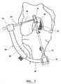
- a partial view of the right knee joint 30includes a tibia section 32 and a femur section 34 articulating therewith in the usual manner.
- the posterior cruciate ligament 36is shown extending between the tibia and the femur but the anterior cruciate ligament is missing.
- a tibial tunnel 38 of standard constructionextends between the anterior surface of the tibia and the tibial plateau.
- a femoral tunnel 40extends from the intercondylar notch towards the lateral femoral aspect and includes a passing pin tunnel 42 which extends from the proximal end 44 of the femoral tunnel to exit at the lateral femoral aspect of the femur 46.
- the method of preparation of the tibial and femoral tunnelsare in accordance with standard techniques known in the art.
- a transverse femoral guide 48 of known constructionincludes a femoral locator 50 comprising an elongate straight rod 52 with a femoral locator head 54 located at the proximal end thereof and which is sized to fit within the femoral socket 40.
- the straight rod section 52is designed to extend from an anchor section 56, through the tibial tunnel and intercondylar notch.
- An arcuate guide arm 58 of standard constructionextends from the lateral side of the anchor 56 in an arcuate manner and includes an adjustable sleeve section 50 for multiple position fixation with respect thereto.
- the head 62 of the guide arm sleeve 60accommodates a. cannulated guide wire bullet 64 which extends therethrough.
- the positioning of the head of the sleeve 62is such that it extends parallel with the femoral locator head 54 and the cannulated bullet extends through an appropriately sized perpendicular aperture in the head of the guide arm sleeve 62 so that it may be advanced towards the head of the femoral locator.
- a small lateral incisionis made on the surface of the knee joint to remove any soft tissue so that the cannulated bullet may be advanced until it firmly locates on the lateral epicondyle.
- the length of the transverse tunnel to be drilledcan be determined from the measurements on the transverse bullet according to known techniques.
- the 2.4mm guide wiremay then be drilled through the femur until it touches the femoral locator. Thereafter, the guide 48 may be removed together with the femoral locator leaving the guide wire 66 in position.
- the guide wire 66is then advanced to penetrate bone on the opposite wall of the femoral tunnel by approximately 1cm.
- the guide wire 66is shown as it is being advanced towards the opposite wall of the femoral tunnel. Thereafter, it may be over drilled with an 8mm cannulated drill 68 to create the transverse tunnel 70 which intersects with the femoral tunnel 40.
- An arthroscope(not shown) may be inserted into the femoral tunnel via the intercondylar notch to assess penetration of the drill 68 into the femoral socket, as the drill should not penetrate the opposite wall of the femoral socket.
- the 2.4mm guide wire pin 66may be removed and replaced with a thinner 1mm guide wire of the transverse screw.
- the cannulated drill 68may be removed.
- a cannulated tap 72is shown being advanced along the transverse tunnel 70 so as to prethread the tunnel in preparation for receiving the transverse suspension device screw. After tapping of the transverse tunnel 70 is complete, the tap 72 may be removed leaving the guide wire in position. The guide wire is then retracted away from the medial wall of the femoral tunnel to provide a gap which is sufficient to allow insertion of the graft into the femoral tunnel.
- a graft loop 74is shown located in position in the femoral tunnel 40.
- the graftincludes sutures 76 threaded therethrough and tied at the proximal end to the end of a passing pin 78.
- the passing pinis advanced through the tibial tunnel, intracondylar notch and femoral tunnel and passed out through the passing pin tunnel 42 to appear at the lateral femoral aspect.
- the suturesmay then be pulled to locate the loop of the graft in the correct position in the femoral tunnel. Care should be taken so that the face of the loop faces the intersection with the transverse tunnel 70.
- the screw guide wire extending down the transverse tunnel 70may then be located under the loop using an arthoscope 80 via the same transverse tunnel 70.
- the arthoscope 80 and guide wiremay be advanced together under the loop and once successively located the arthoscope may be retracted and removed taking care to retain the guide wire in position.
- a dilation device 100having a tubular shaft 102, a handle section 104 and a nose section 108.
- the nose section 108is frustoconical in shape, and has a rounded leading end 110.
- the frustoconical sectionextends distally from a shoulder section 106 at the trailing end thereof, the said shoulder section extending proximally with a constant cross-section as far as the shaft 102, co-axial therewith but of a slightly larger cross-section than the shoulder.
- the dilation device 100is cannulated 112 along the entire length thereof so as to be passed along the guide wire such that it dilates the graft loop 74 as it passes transversely through the bone tunnel.
- the dilation device 100is advanced along the guide wire with sufficient force to create a recess in the opposite wall of the femoral tunnel in which the frustoconical nose section 12 of the suspension device 2 may be accommodated. Accordingly, the dilation device is suitably dimensioned to be complimentary to the suspension device in this respect.
- the dilation device 100is then retracted leaving the graft loop 74 sufficiently dilated such that the suspension device 2 can be advanced therethrough. When retracting the dilation device 100, care is taken to retain the guide wire in position.
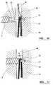
- the cannulated screwis shown located over the guide wire and advancing towards the dilated graft loop 74
- the suspension device 2is shown fully advanced into the femoral tunnel with its frustoconical nose section 12 embedded in the recess 13 formed in the opposite wall of the femoral tunnel.
- the body section 4being of a wider diameter than the trailing part of the head section 6, provides an annular abutment for the graft loop residing on the trailing part 10 and as the suspension device advances the annular abutment urges the graft loop against the opposite wall of the bone tunnel thus encouraging the graft and the bone to graft to each other.
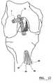
- the guide wiremay be removed.
- the final position of the cannulated transverse suspension device screwis shown in figure 12 with the outer wall of the head of the screw and the leading end of the body section urging the graft into contact with the walls of the femoral tunnel.
- the trailing ends of the graft 82, 84,86, 88may be fixed to the tibia in accordance with the surgeons preference and in accordance with techniques known in the art.
- a suitable type of graft for use with the present inventionis a double-looped semitendinosus and gracilis (DLSTG) hamstring graft which may be prepared in accordance with techniques known in the art.
- DLSTGdouble-looped semitendinosus and gracilis
- a suitable material for the screwwould be a combination of ceramic and polymer materials.
- a suitable ceramic componentcould be tri-calcium phosphate or ceramic hydroxyapetite. However, any suitable bio ceramic may be used.
- the polymer componentmay incorporate poly lactic acid to provide good biocompatibility.
Landscapes
- Health & Medical Sciences (AREA)
- Vascular Medicine (AREA)
- Animal Behavior & Ethology (AREA)
- Rheumatology (AREA)
- Cardiology (AREA)
- Oral & Maxillofacial Surgery (AREA)
- Transplantation (AREA)
- Engineering & Computer Science (AREA)
- Biomedical Technology (AREA)
- Heart & Thoracic Surgery (AREA)
- Orthopedic Medicine & Surgery (AREA)
- Rehabilitation Therapy (AREA)
- General Health & Medical Sciences (AREA)
- Life Sciences & Earth Sciences (AREA)
- Public Health (AREA)
- Veterinary Medicine (AREA)
- Surgical Instruments (AREA)
- Prostheses (AREA)
- Vehicle Body Suspensions (AREA)
- Clamps And Clips (AREA)
- Fluid-Damping Devices (AREA)
- Body Structure For Vehicles (AREA)
Abstract
Description
- The present invention relates to a transverse suspension device, in particular, but not exclusively, a transverse suspension screw for anterior cruciate ligament (ACL) fixation in the femoral tunnel.
- Transverse securing devices are being increasingly used for secure fixation of ACL replacement grafts in the femoral tunnel during ACL reconstruction surgery. One such device known as the bone mulch™ screw is available from ArthrotekR.
- The bone mulch screw has a hollow body section with an opening at either end thereof. The tip of the screw is stepped having a sharp narrow leading section followed by a slightly wider trailing section. The trailing end of the tip is joined to the body section on one side of the said body section only, leaving a gap at the leading end of the body section so that bone mulch material can be forced therethrough and into the femoral tunnel after fixation. A suture passing loop must be located over the end of the partially inserted tip in the femoral tunnel and it is for this reason that the tip is stepped so that the leading end is as narrow as possible to maximise efficiency in the difficult step of locating a suture loop over the leading end of the bone mulch tip when it first protrudes into the femoral tunnel. Once the suture loop is in position, the bone mulch screw may be advanced further so that the stepped tip bores through the medial wall of the femoral tunnel until the thicker section of the tip fully extends transversely across the tunnel. The graft may then be pulled into the tunnel by passing it over the transverse pin after attaching it to one end of the looped suture and pulling the other end. Unfortunately, because the graft must be pulled over the pin at the blind end of the femoral tunnel it is necessary to ream out bone from inside the femoral tunnel so as to create sufficient space for the graft to be pulled over the pin without becoming caught between the end of the femoral tunnel and the pin. By reaming out bone from the end of the femoral tunnel, the compression of the graft against the tunnel wall is decreased lengthening the process of healing and fixation. Furthermore, the looping of the suture is not a straightforward step and requires an arthroscopic view via the tibial tunnel and may also require several attempts before the loop is successfully located over the leading end of the tip.
- Alternatives to such transverse suspension pins include interference cross pins which interfere against a bone block in bone-patella tendon-bone graft fixation. A suitable device for such procedures is the BiLok™ screw. However, such techniques are not appropriate for pure tendon grafts such as the double-looped semitendinosus and gracilis (DLSTG) hamstring graft which is one of the strongest and stiffest grafts available and does not suffer from a number of complications associated with the bone-patella tendon-bone graft.
EP-A-1,180,351 upon which the preamble of claim 1 is based describes an apparatus and method for reconstructing a ligament in which a cannulated cross pin is used for transverse fixation of a plate attached to the bone block of a graft ligament in a bone tunnel.FR-A-2732211 - The invention is set out in Claim 1 and preferred features of the invention are set out in the dependent claims.
- There is described herein a transverse suspension device for ACL graft fixation in a femoral bone tunnel comprising a body section and a smooth head section forming the leading end of the device, the body and smooth head sections each being cannulated along the entire lengths thereof; the head section comprising a recess engaging section extending proximally from the distal end thereof and operable to engage with a recess formed in the bone tunnel, and an abutment surface located between the body section and the recess engaging section adapted to urge the graft against the opposite wall of the bone tunnel in use. A device embodying the invention thus encouraging the bone and the graft loop to graft to each other.
- The device comprises a graft loop support section between the recess engaging section and the body section adapted to stably support a graft loop thereover. By the term stably support, is meant that the portion of the graft loop located over the loop support section is prevented from movement along the longitudinal axis of a femoral or other bone tunnel in which the device is located transverse thereto.
- Preferably, the graft loop support section is of constant, preferably, circular, cross section. Typically, the head section is located on the same longitudinal axis as the body section.
- Preferably, at least a part of the recess engaging section tapers outwardly from the leading end thereof. Preferably, the recess engaging section comprises a rounded nose section at the leading end thereof which, preferably, terminates the tapered section at the leading end of the device. Preferably, at least the major part of the recess engaging section is frustoconical.
- Preferably, the device is cannulated along the entire length thereof. Preferably, the head section extends distally from the distal end of the body section.
- Preferably, the body section is suitably adapted for secure fixation, in use, in a tunnel transverse to the femoral tunnel, preferably, by interference with the tunnel wall. The body section is externally threaded so that the device may be conveniently screwed into position.
- As mentioned above, preferably, at least a part of the smooth head tapers outwardly from the leading end thereof to form a tapered section of the head. The smooth head may also include a non-tapered section between the tapered section and the body section previously described as the graft loop support section. Preferably, the widest diameter of the smooth head is less than the outer diameter of the body section. Preferably, the body section itself is not tapered but has a substantially uniform overall diameter along the length thereof subject to thread undulations or protrusions on the exterior surface thereof. The cannulated interior of the device may be wider at its trailing end to accommodate a suitable fixation device to assist location of the device in position.
- Advantageously, by having the body and head section, cannulated, the device may be advanced along a guide wire and located under the loop of a graft pre-positioned in the femoral tunnel. An additional advantage is provided by the tapered head section which increasingly compresses the graft as it advances thereunder during fixation. A threaded or ribbed body section may still further compress the graft forwards and outwards when the smooth head is short enough to completely advance beneath the first loop so that then the body section impinges on the graft directly. However, compression is chiefly effected by an abutment surface at the distal end of the body section. Preferably, the abutment surface is in the form of a flange, which is, preferably, annular. Graft compression advantageously contributes to graft incorporation by assisting tunnel wall bonding of the graft. The abutment surface may be a flange.
- An exemplary method of using a device embodying the present invention comprises the steps of:-
- forming a femoral tunnel for graft fixation therein;
- forming a transverse tunnel for intersecting the femoral tunnel;
- locating a graft loop in the femoral tunnel in such a manner that the open face of the loop faces the intersection of the transverse tunnel,
- passing at least a part of the head section of a transverse suspension device according to the present invention through the graft loop via the transverse tunnel.
- By passing the smooth head of the device through the graft loop, the graft is progressively compressed outwardly against the femoral tunnel walls before being stably located therein via the graft loop support section.
- Preferably, after location of the graft loop in the femoral tunnel, a guide wire is advanced thereunder from the transverse tunnel using a suitable viewing device such as an arthroscope. The suspension device may then be passed along the guide wire.
- Preferably, a dilation device is passed along the guide wire prior to the suspension device to dilate the loop in the graft after the guide wire is advanced thereunder, and, preferably, the dilation device is forced into the opposite wall of the femoral tunnel to create a recess therein.
- The dilation device may then be removed and the suspension device may then be passed along the guide wire.
- Preferably, the suspension device is advanced under the graft loop. Preferably, the recess engaging section is advanced into the recess in the opposite wall of the femoral tunnel and, preferably, the body section is advanced into the femoral tunnel. Preferably, the abutment surface of the body section urges the graft loop onto the opposite wall of the femoral tunnel.
- Advantageously, the insertion of the dilation device opens the graft loop allowing the suspension device to pass freely thereunder.
- Advantageously, the smooth surface of the head section prevents damage to the graft during its fixation and the method of locating the head section under the loop avoids the need for complex suture loop passing and looping steps. Furthermore, because the head section compresses the graft loop directly against the walls of the femoral tunnel in a single step, damage to the graft is minimised.
- Preferably, the head of the device is advanced as far as the opposite wall of the femoral tunnel. The head may also be advanced into the opposite tunnel wall a short distance to provide more secure fixation, if required.
- However, as the cannulation extends through the head section the leading tip of the head section does not typically terminate in a sharp point but is typically rounded into a convex tip with a centrally disposed cannular hole.
- Preferably, the diameter of the cannular hole at the tip of the device is in the range 0.1-3mm, more preferably 0.5-1.5mm, most preferably 0.8-1.2mmm.
- Preferably, the diameter of the cannular hole at the trailing end of the device is between 0.1-15.0mm, more preferably 1-10mm, most preferably 2-8mm.
- Preferably, the length of the head section is between 1-25mm, more preferably between 2-20mm, most preferably between 5-15mm.
- Preferably, the length of the body section is between 5-50mm, more preferably between 10-40mm, most preferably between 20-30mm.
- Preferably, the maximum width of the head section is between 1-15mm, more preferably between 2-8mm, most preferably, between 3-8mm. An especially preferred width is 5-7mm.
- Preferably, the width of the body section excluding any protrusions is between 2-15mm, more preferably, between 3-12mm, most preferably 5-12mm.
- Preferably, the minimum width of the graft loop support section of the head section, is between 0.5-10mm, more preferably, between 2-8mm, most preferably, between 2-5mm.
- Preferably, the trailing end of the device is adapted to receive a suitable tool for use during fixation of the device. The tool is preferably suitable to locate the device in the transverse tunnel via a push fit or screw fit mechanism.
- An embodiment of the invention will now be described by way of example only and with reference to the accompanying drawings in which:
Figure 1 is a perspective view of a transverse suspension device in accordance with the present invention;Figure 2 is a trailing end view of the transverse suspension device offigure 1 ;Figure 3 is a sectional view through the transverse suspension device offigure 1 ;Figure 4 is a partial view of the right knee joint showing the femoral and tibial tunnels prepared for ACL reconstruction;Figure 5 is a partial view of the right knee joint illustrating the use of an A-Tech guide;Figure 6 is the view offigure 4 showing the drilling of the transverse tunnel;Figure 7 is a view offigure 4 showing the guide wire and tap in position;Figure 8 is a view offigure 4 showing the graft being pulled into position;Figure 9 is a cross sectional view of a dilation device;Figure 10 is a cross sectional view of the femoral tunnel prior to location of the suspension device;Figure 11 is a cross sectional view of the femoral tunnel with the suspension device in place; andFigure 12 is a view offigure 4 showing the transverse suspension device stably securing the graft loop in the femoral tunnel.- Referring to
figures 1, 2 and 3 , atransverse suspension device 2 has atubular body section 4 and aco-axial head section 6 joined to and protruding from theleading end 8 of thebody section 4. Thetransverse suspension device 2 is cannulated along the length of the axis thereof so that it may be passed along a guide wire in use. Thebody section 4 is externally screw threaded along its entire length and thehead section 6 includes a trailingpart 10 coaxial with thebody section 4 but of a narrower outer diameter and afrustoconical nose section 12 extending from the leading end of the trailingpart 10 and having the narrower end forming the leading end of the nose section. The tip of the nose section is rounded in a convex manner and includes theexit port 14 of the cannulated hole of the device at its centre. - The hollow interior of the device extends from the trailing end in the form of a central tubular recess which is stepped into a radially
narrower keyhole section 20, midway along the length of the body section, which extends forwardly through the remainder of the body section as far as the leading end thereof. Thekeyhole section 20 includes three radially inwardly directed longitudinally extendingvanes - Referring to
figure 4 , a partial view of the right knee joint 30 includes atibia section 32 and afemur section 34 articulating therewith in the usual manner. In the illustration shown, the posteriorcruciate ligament 36 is shown extending between the tibia and the femur but the anterior cruciate ligament is missing. Atibial tunnel 38 of standard construction extends between the anterior surface of the tibia and the tibial plateau. Afemoral tunnel 40 extends from the intercondylar notch towards the lateral femoral aspect and includes a passingpin tunnel 42 which extends from theproximal end 44 of the femoral tunnel to exit at the lateral femoral aspect of thefemur 46. The method of preparation of the tibial and femoral tunnels are in accordance with standard techniques known in the art. - Referring to
figure 5 , a transversefemoral guide 48 of known construction includes afemoral locator 50 comprising an elongatestraight rod 52 with afemoral locator head 54 located at the proximal end thereof and which is sized to fit within thefemoral socket 40. Thestraight rod section 52 is designed to extend from ananchor section 56, through the tibial tunnel and intercondylar notch. Anarcuate guide arm 58 of standard construction extends from the lateral side of theanchor 56 in an arcuate manner and includes anadjustable sleeve section 50 for multiple position fixation with respect thereto. Thehead 62 of theguide arm sleeve 60 accommodates a. cannulatedguide wire bullet 64 which extends therethrough. The positioning of the head of thesleeve 62 is such that it extends parallel with thefemoral locator head 54 and the cannulated bullet extends through an appropriately sized perpendicular aperture in the head of theguide arm sleeve 62 so that it may be advanced towards the head of the femoral locator. In use, a small lateral incision is made on the surface of the knee joint to remove any soft tissue so that the cannulated bullet may be advanced until it firmly locates on the lateral epicondyle. The length of the transverse tunnel to be drilled can be determined from the measurements on the transverse bullet according to known techniques. The 2.4mm guide wire may then be drilled through the femur until it touches the femoral locator. Thereafter, theguide 48 may be removed together with the femoral locator leaving theguide wire 66 in position. Theguide wire 66 is then advanced to penetrate bone on the opposite wall of the femoral tunnel by approximately 1cm. - Referring to
figure 6 , theguide wire 66 is shown as it is being advanced towards the opposite wall of the femoral tunnel. Thereafter, it may be over drilled with an 8mm cannulateddrill 68 to create thetransverse tunnel 70 which intersects with thefemoral tunnel 40. An arthroscope (not shown) may be inserted into the femoral tunnel via the intercondylar notch to assess penetration of thedrill 68 into the femoral socket, as the drill should not penetrate the opposite wall of the femoral socket. At this point in the procedure, the 2.4mmguide wire pin 66 may be removed and replaced with a thinner 1mm guide wire of the transverse screw. Thereafter, the cannulateddrill 68 may be removed. - Referring to
figure 7 , a cannulatedtap 72 is shown being advanced along thetransverse tunnel 70 so as to prethread the tunnel in preparation for receiving the transverse suspension device screw. After tapping of thetransverse tunnel 70 is complete, thetap 72 may be removed leaving the guide wire in position. The guide wire is then retracted away from the medial wall of the femoral tunnel to provide a gap which is sufficient to allow insertion of the graft into the femoral tunnel. - Referring to
figure 8 , agraft loop 74 is shown located in position in thefemoral tunnel 40. The graft includessutures 76 threaded therethrough and tied at the proximal end to the end of a passingpin 78. In practice, the passing pin is advanced through the tibial tunnel, intracondylar notch and femoral tunnel and passed out through the passingpin tunnel 42 to appear at the lateral femoral aspect. The sutures may then be pulled to locate the loop of the graft in the correct position in the femoral tunnel. Care should be taken so that the face of the loop faces the intersection with thetransverse tunnel 70. The screw guide wire extending down thetransverse tunnel 70 may then be located under the loop using anarthoscope 80 via the sametransverse tunnel 70. Thearthoscope 80 and guide wire may be advanced together under the loop and once successively located the arthoscope may be retracted and removed taking care to retain the guide wire in position. - Referring to
figure 9 , adilation device 100 is shown having atubular shaft 102, ahandle section 104 and anose section 108. Thenose section 108 is frustoconical in shape, and has a roundedleading end 110. The frustoconical section extends distally from ashoulder section 106 at the trailing end thereof, the said shoulder section extending proximally with a constant cross-section as far as theshaft 102, co-axial therewith but of a slightly larger cross-section than the shoulder. Thedilation device 100 is cannulated 112 along the entire length thereof so as to be passed along the guide wire such that it dilates thegraft loop 74 as it passes transversely through the bone tunnel. Thedilation device 100, is advanced along the guide wire with sufficient force to create a recess in the opposite wall of the femoral tunnel in which thefrustoconical nose section 12 of thesuspension device 2 may be accommodated. Accordingly, the dilation device is suitably dimensioned to be complimentary to the suspension device in this respect. Thedilation device 100 is then retracted leaving thegraft loop 74 sufficiently dilated such that thesuspension device 2 can be advanced therethrough. When retracting thedilation device 100, care is taken to retain the guide wire in position. - Referring to
figure 10 , the cannulated screw is shown located over the guide wire and advancing towards the dilatedgraft loop 74 - Referring to
figure 11 , thesuspension device 2 is shown fully advanced into the femoral tunnel with itsfrustoconical nose section 12 embedded in therecess 13 formed in the opposite wall of the femoral tunnel. Thebody section 4 being of a wider diameter than the trailing part of thehead section 6, provides an annular abutment for the graft loop residing on the trailingpart 10 and as the suspension device advances the annular abutment urges the graft loop against the opposite wall of the bone tunnel thus encouraging the graft and the bone to graft to each other. - Thereafter, the guide wire may be removed. The final position of the cannulated transverse suspension device screw is shown in
figure 12 with the outer wall of the head of the screw and the leading end of the body section urging the graft into contact with the walls of the femoral tunnel. The trailing ends of thegraft - A suitable type of graft for use with the present invention is a double-looped semitendinosus and gracilis (DLSTG) hamstring graft which may be prepared in accordance with techniques known in the art.
- A suitable material for the screw would be a combination of ceramic and polymer materials. A suitable ceramic component could be tri-calcium phosphate or ceramic hydroxyapetite. However, any suitable bio ceramic may be used. The polymer component may incorporate poly lactic acid to provide good biocompatibility.
Claims (5)
- A transverse suspension device for ACL graft fixation in a femoral bone tunnel (40) comprising a body section (4) and a smooth head section (6) forming the leading end of the device, the body and smooth head sections each being cannulated along the entire lengths thereof;
the head section comprising:a graft loop support section (10) extending, distally from the distal end of the body section (4) and adapted to stably support a graft loop (74) thereover;a recess engaging section (12) extending distally from the distal end of the graft loop support section and operable to engage with a recess (13) formed in the bone tunnel (70);the body section (4) being externally threaded; the suspension devicecharacterised in that the body section (4) comprises an abutment surface annularly surrounding the graft loop support section at the distal end of the body section and adapted to urge the graft loop (74) against the opposite wall of the bone tunnel (40), in use. - A device as claimed in any preceding claim, wherein the body section (4) is adapted for secure fixation, in use, in a tunnel transverse to the femoral tunnel (40).
- A device as claimed in any preceding claim, wherein at least part of the smooth head section (6) tapers outwardly from the leading end thereof to form a tapered section of the head.
- A device as claimed in any preceding claim, wherein the graft loop support section (10) is of constant cross-section.
- A device as claimed in any preceding claim, wherein the abutment surface comprises a flange.
Applications Claiming Priority (3)
| Application Number | Priority Date | Filing Date | Title |
|---|---|---|---|
| GB0208667 | 2002-04-16 | ||
| GBGB0208667.6AGB0208667D0 (en) | 2002-04-16 | 2002-04-16 | A transverse suspension device |
| PCT/GB2003/001606WO2003088874A1 (en) | 2002-04-16 | 2003-04-15 | A transverse suspension device |
Publications (2)
| Publication Number | Publication Date |
|---|---|
| EP1494622A1 EP1494622A1 (en) | 2005-01-12 |
| EP1494622B1true EP1494622B1 (en) | 2009-03-18 |
Family
ID=9934901
Family Applications (1)
| Application Number | Title | Priority Date | Filing Date |
|---|---|---|---|
| EP03718937AExpired - LifetimeEP1494622B1 (en) | 2002-04-16 | 2003-04-15 | A transverse suspension device |
Country Status (7)
| Country | Link |
|---|---|
| US (1) | US7713293B2 (en) |
| EP (1) | EP1494622B1 (en) |
| AT (1) | ATE425721T1 (en) |
| AU (1) | AU2003222971A1 (en) |
| DE (1) | DE60326708D1 (en) |
| GB (1) | GB0208667D0 (en) |
| WO (1) | WO2003088874A1 (en) |
Families Citing this family (18)
| Publication number | Priority date | Publication date | Assignee | Title |
|---|---|---|---|---|
| US7195642B2 (en)* | 2001-03-13 | 2007-03-27 | Mckernan Daniel J | Method and apparatus for fixing a graft in a bone tunnel |
| US7901404B2 (en) | 2004-01-16 | 2011-03-08 | Arthrocare Corporation | Bone harvesting device and method |
| US8986345B2 (en)* | 2004-12-07 | 2015-03-24 | Biomet Sports Medicine, Llc | Expanding suture anchor having an actuator pin |
| US7976565B1 (en) | 2004-12-07 | 2011-07-12 | Biomet Sports Medicine, Llc | Expanding suture anchor having an actuator pin |
| US7572283B1 (en)* | 2004-12-07 | 2009-08-11 | Biomet Sports Medicine, Llc | Soft tissue rivet and method of use |
| US7527648B2 (en)* | 2004-12-21 | 2009-05-05 | Mitek Surgical Products Div Of Ethicon, Inc. | Method of replacing an anterior cruciate ligament in the knee |
| US7458975B2 (en)* | 2004-12-21 | 2008-12-02 | Johnson & Johnson | Method of replacing an anterior cruciate ligament in the knee |
| US20060178673A1 (en)* | 2005-02-09 | 2006-08-10 | Arthrocare Corporation | Lockable slide hammer and gripping apparatus |
| US7591850B2 (en) | 2005-04-01 | 2009-09-22 | Arthrocare Corporation | Surgical methods for anchoring and implanting tissues |
| US7842042B2 (en) | 2005-05-16 | 2010-11-30 | Arthrocare Corporation | Convergent tunnel guide apparatus and method |
| US7686838B2 (en) | 2006-11-09 | 2010-03-30 | Arthrocare Corporation | External bullet anchor apparatus and method for use in surgical repair of ligament or tendon |
| US7794484B2 (en)* | 2007-05-07 | 2010-09-14 | Biomet Sports Medicine, Llc | Fixation device for delivery of biological material between soft tissue and bone |
| CA2702952C (en) | 2007-10-27 | 2017-01-03 | Parcus Medical, Llc | Suture anchor |
| US20110015643A1 (en)* | 2008-03-31 | 2011-01-20 | Paulos Lonnie E | Ligament reconstruction guide assembly and methods of use |
| US8333802B2 (en)* | 2008-08-19 | 2012-12-18 | Dougherty Christopher P | Single tunnel double bundle anterior cruciate ligament reconstruction |
| US8449612B2 (en) | 2009-11-16 | 2013-05-28 | Arthrocare Corporation | Graft pulley and methods of use |
| US8617176B2 (en) | 2011-08-24 | 2013-12-31 | Depuy Mitek, Llc | Cross pinning guide devices and methods |
| EP2967535A4 (en) | 2013-03-15 | 2016-11-16 | Mark Brunsvold | Suture anchor |
Citations (1)
| Publication number | Priority date | Publication date | Assignee | Title |
|---|---|---|---|---|
| US5918604A (en)* | 1997-02-12 | 1999-07-06 | Arthrex, Inc. | Method of loading tendons into the knee |
Family Cites Families (189)
| Publication number | Priority date | Publication date | Assignee | Title |
|---|---|---|---|---|
| US1727590A (en) | 1926-09-16 | 1929-09-10 | Ferry Thomas | Cap nut |
| US2778357A (en)* | 1952-11-06 | 1957-01-22 | Leibinger Ludwig | Biopsy punch |
| FR2213761B1 (en)* | 1973-01-17 | 1976-05-14 | Rambert Andre | |
| GB1465744A (en) | 1974-01-30 | 1977-03-02 | Ethicon Inc | Attaching fibrous connective tissue to bone |
| US3905356A (en) | 1974-05-15 | 1975-09-16 | Nasa | Subminiature insertable force transducer |
| US3974621A (en) | 1975-03-17 | 1976-08-17 | Stang Micheal O | Wedge-bolted joint |
| US4149277A (en) | 1977-06-22 | 1979-04-17 | General Atomic Company | Artificial tendon prostheses |
| US4204544A (en)* | 1977-09-30 | 1980-05-27 | California Institute Of Technology | Simultaneous muscle force and displacement transducer |
| US4126165A (en) | 1977-10-14 | 1978-11-21 | Guignard Gelas S | Wood lathe chisel |
| US4187558A (en)* | 1977-10-25 | 1980-02-12 | Cutter Laboratories, Inc. | Prosthetic ligament |
| US4309778A (en)* | 1979-07-02 | 1982-01-12 | Biomedical Engineering Corp. | New Jersey meniscal bearing knee replacement |
| US4275717A (en)* | 1979-07-27 | 1981-06-30 | Zimmer Usa, Inc. | Intramedullary fixation device for fractured tubular bones |
| US4335715A (en)* | 1980-06-20 | 1982-06-22 | Kirkley William H | Osteotomy guide |
| US4347024A (en) | 1980-08-22 | 1982-08-31 | Eaton Corporation | Tension indicating and lock cone washer |
| US4406281A (en) | 1981-04-14 | 1983-09-27 | Tecnol, Inc. | Fluid impermeable cover for operating room tourniquet |
| US5601557A (en)* | 1982-05-20 | 1997-02-11 | Hayhurst; John O. | Anchoring and manipulating tissue |
| US4530357A (en)* | 1983-04-18 | 1985-07-23 | Pawloski James A | Fluid actuated orthopedic tool |
| CH662263A5 (en)* | 1983-09-13 | 1987-09-30 | Gegauf Fritz Ag | HYSTERECTOMIUM. |
| US4573448A (en)* | 1983-10-05 | 1986-03-04 | Pilling Co. | Method for decompressing herniated intervertebral discs |
| US4583554A (en)* | 1984-06-12 | 1986-04-22 | Medpar Ii | Knee ligament testing device |
| US4600005A (en)* | 1984-08-22 | 1986-07-15 | Hendel Philip M | Guided osteotome for harvesting cranial bone graft |
| FR2590792B1 (en) | 1985-12-04 | 1992-09-18 | Breard Francis | LIGAMENT CLIP, PARTICULARLY FOR THE IMPLANTATION OF ARTIFICIAL ARTICULAR LIGAMENTS |
| US4708132A (en) | 1986-01-24 | 1987-11-24 | Pfizer-Hospital Products Group, Inc. | Fixation device for a ligament or tendon prosthesis |
| US4820279A (en)* | 1986-03-31 | 1989-04-11 | Dedo Richard G | Article and method for prepping a patient prior to surgery |
| US4712542A (en) | 1986-06-30 | 1987-12-15 | Medmetric Corporation | System for establishing ligament graft orientation and isometry |
| ZA875425B (en) | 1986-07-23 | 1988-04-27 | Gore & Ass | Mechanical ligament |
| SU1521465A1 (en) | 1987-01-13 | 1989-11-15 | Научно-производственное объединение "Мединструмент" | Trochar |
| US4898156A (en) | 1987-05-18 | 1990-02-06 | Mitek Surgical Products, Inc. | Suture anchor |
| US5037426A (en) | 1988-09-19 | 1991-08-06 | Marlowe Goble E | Procedure for verifying isometric ligament positioning |
| US4910901A (en)* | 1988-09-19 | 1990-03-27 | Boyar Florene E | Sign post assembly |
| US4969471A (en) | 1989-01-09 | 1990-11-13 | Medmetric Corporation | Knee ligament testing device and method of use |
| US4950270A (en) | 1989-02-03 | 1990-08-21 | Boehringer Mannheim Corporation | Cannulated self-tapping bone screw |
| US4927421A (en)* | 1989-05-15 | 1990-05-22 | Marlowe Goble E | Process of endosteal fixation of a ligament |
| JPH066810Y2 (en) | 1989-11-29 | 1994-02-23 | 旭光学工業株式会社 | Vertebral body fixation plate |
| US4997433A (en)* | 1990-01-16 | 1991-03-05 | Marlowe Goble E | Endosteal fixation stud and system |
| USD330591S (en) | 1990-01-31 | 1992-10-27 | American Cyanamid Company | Suture anchor driver |
| US5139520A (en) | 1990-01-31 | 1992-08-18 | American Cyanamid Company | Method for acl reconstruction |
| DE9002844U1 (en) | 1990-03-10 | 1990-12-06 | Giers, Roland, 4950 Minden | Button for fastening tape and suture material |
| US5037422A (en) | 1990-07-02 | 1991-08-06 | Acufex Microsurgical, Inc. | Bone anchor and method of anchoring a suture to a bone |
| US5258016A (en) | 1990-07-13 | 1993-11-02 | American Cyanamid Company | Suture anchor and driver assembly |
| US5385567A (en)* | 1990-09-07 | 1995-01-31 | Goble; E. Marlowe | Sight barrel arthroscopic instrument |
| US5626609A (en)* | 1990-10-05 | 1997-05-06 | United States Surgical Corporation | Endoscopic surgical instrument |
| US5489292A (en)* | 1990-10-05 | 1996-02-06 | United States Surgical Corporation | Endoscopic surgical instrument with grip enhancing means |
| US5350393A (en)* | 1992-01-06 | 1994-09-27 | Inbae Yoon | Safety trocar penetrating instrument |
| US5112338A (en)* | 1991-02-11 | 1992-05-12 | Anspach Iii William E | Surgical instrument for removing artificial acetabular cups |
| US5152790A (en) | 1991-03-21 | 1992-10-06 | American Cyanamid Company | Ligament reconstruction graft anchor apparatus |
| US5170800A (en) | 1991-04-04 | 1992-12-15 | Symbiosis Corporation | Hermaphroditic endoscopic claw extractors |
| US5395375A (en)* | 1992-11-18 | 1995-03-07 | Symbiosis Corporation | Arthroscopic surgical instruments |
| US5176699A (en)* | 1991-06-05 | 1993-01-05 | Harold Markham | Surgical device with double jaw actuation |
| US5228448A (en)* | 1991-09-03 | 1993-07-20 | Byrd Timothy N | Protective cover for blood-pressure cuffs |
| FR2683715B1 (en) | 1991-11-14 | 1995-07-07 | Bahuaud Jacques | TEXTILE PROSTHESIS OF LIGAMENT CROSS ANTERIOR KNEE. |
| US5254129A (en) | 1991-11-22 | 1993-10-19 | Alexander Chris B | Arthroscopic resector |
| US5391169A (en)* | 1991-12-13 | 1995-02-21 | Mcguire; David A. | Patellar tendon harvester |
| AU672596B2 (en) | 1992-02-14 | 1996-10-10 | Smith & Nephew, Inc. | Polymeric screws and coatings for surgical uses |
| US5350383A (en) | 1992-02-20 | 1994-09-27 | Arthrex, Inc. | Adjustable drill guide with interchangeable marking hooks |
| US5562664A (en) | 1992-02-20 | 1996-10-08 | Arthrex Inc. | Drill guide with target PCL-oriented marking hook |
| US5383471A (en)* | 1992-04-10 | 1995-01-24 | Funnell; David M. | Surgical biopsy instrument |
| US5258003A (en) | 1992-06-01 | 1993-11-02 | Conmed Corporation | Method and apparatus for induction of pneumoperitoneum |
| US5176682A (en)* | 1992-06-01 | 1993-01-05 | Chow James C Y | Surgical implement |
| US5251646A (en) | 1992-06-29 | 1993-10-12 | Thomas Bowen | Protective covering for a sphygmomanometer cuff |
| FR2693364B1 (en)* | 1992-07-07 | 1995-06-30 | Erpios Snc | INTERVERTEBRAL PROSTHESIS FOR STABILIZING ROTATORY AND FLEXIBLE-EXTENSION CONSTRAINTS. |
| US5266075A (en) | 1992-10-05 | 1993-11-30 | Roy Clark | Tendon threader for endosteal ligament mounting |
| US5683359A (en) | 1992-11-18 | 1997-11-04 | Symbiosis Corporation | Arthroscopic surgical instruments having suction capability |
| US5350380A (en) | 1993-01-15 | 1994-09-27 | Depuy Inc. | Method for securing a ligament replacement in a bone |
| US5303472A (en)* | 1993-01-26 | 1994-04-19 | Mbanugo Linus O | Card dicer apparatus |
| US5431651A (en)* | 1993-02-08 | 1995-07-11 | Goble; E. Marlowe | Cross pin and set screw femoral and tibial fixation method |
| US5306301A (en)* | 1993-02-11 | 1994-04-26 | American Cyanamid Company | Graft attachment device and method of using same |
| US6270304B1 (en)* | 1993-03-23 | 2001-08-07 | Yosef Freedland | Tension adjusting device |
| US5423860A (en)* | 1993-05-28 | 1995-06-13 | American Cyanamid Company | Protective carrier for suture anchor |
| US5632748A (en)* | 1993-06-14 | 1997-05-27 | Linvatec Corporation | Endosteal anchoring device for urging a ligament against a bone surface |
| JP3180219B2 (en) | 1993-07-09 | 2001-06-25 | ニプロ株式会社 | Trocar |
| EP0710392B1 (en) | 1993-07-19 | 2001-11-07 | Quantum Corporation | Magnetic head with self-regulating wear regions |
| US5529424A (en)* | 1993-07-21 | 1996-06-25 | Hafele Gmbh & Co. | Dowel-type pin for connecting components, particularly furniture plates |
| US5408359A (en)* | 1993-09-20 | 1995-04-18 | The United States Of America As Represented By The Secretary Of The Army | Visual security eyecup |
| US5330468A (en)* | 1993-10-12 | 1994-07-19 | Burkhart Stephen S | Drill guide device for arthroscopic surgery |
| US5405359A (en)* | 1994-04-29 | 1995-04-11 | Pierce; Javi | Toggle wedge |
| US5324308A (en)* | 1993-10-28 | 1994-06-28 | Javin Pierce | Suture anchor |
| US5618314A (en)* | 1993-12-13 | 1997-04-08 | Harwin; Steven F. | Suture anchor device |
| AU689846B2 (en) | 1994-03-29 | 1998-04-09 | Zimmer Gmbh | Screw made of biodegradable material for bone surgery purposes, and screwdriver suitable therefor |
| US5620001A (en)* | 1994-04-26 | 1997-04-15 | Byrd; Timothy N. | Universal blood-pressure cuff cover |
| GB2288739A (en) | 1994-04-27 | 1995-11-01 | Corin Medical Ltd | Surgical anchor |
| US5782749A (en) | 1994-05-10 | 1998-07-21 | Riza; Erol D. | Laparoscopic surgical instrument with adjustable grip |
| US5480444A (en) | 1994-06-02 | 1996-01-02 | Incavo; Stephen J. | Hybrid tibial tray knee prosthesis |
| US5472452A (en) | 1994-08-30 | 1995-12-05 | Linvatec Corporation | Rectilinear anchor for soft tissue fixation |
| FR2725615B1 (en) | 1994-10-17 | 1997-06-13 | Caffiniere Jean Yves De | BONE ANCHORING DEVICE FOR FIXATION THREADS USED IN ORTHOPEDIC SURGERY |
| US5649963A (en) | 1994-11-10 | 1997-07-22 | Innovasive Devices, Inc. | Suture anchor assembly and methods |
| US5674224A (en)* | 1994-11-18 | 1997-10-07 | Howell; Stephen M. | Bone mulch screw assembly for endosteal fixation of soft tissue grafts and method for using same |
| US6802862B1 (en) | 1995-01-24 | 2004-10-12 | Smith & Nephew, Inc. | Method for soft tissue reconstruction |
| US5601562A (en)* | 1995-02-14 | 1997-02-11 | Arthrex, Inc. | Forked insertion tool and metnod of arthroscopic surgery using the same |
| US5643273A (en)* | 1995-02-17 | 1997-07-01 | Clark; Ron | ACL bone tunnel projection drill guide and method for its use |
| US5840078A (en) | 1995-03-01 | 1998-11-24 | Yerys; Paul | Method and apparatus for mechanical attachment of soft tissue to bone tissue |
| FR2732211A1 (en)* | 1995-03-28 | 1996-10-04 | Boyer Thierry | Fastening implant for repairing damaged upper arm muscles |
| US5591232A (en)* | 1995-04-17 | 1997-01-07 | Rahimi; Houching | Surgical method for rejuvenating body members or for reshaping body members or for rejuvenating and reshaping body members by bone grafting |
| US5643266A (en)* | 1995-06-05 | 1997-07-01 | Li Medical Technologies, Inc. | Method and apparatus for securing ligaments |
| US6117161A (en) | 1995-06-06 | 2000-09-12 | Li Medical Tecnologies, Inc. | Fastener and fastening method, particularly for fastening sutures to bone |
| US5791350A (en) | 1995-06-07 | 1998-08-11 | Morton; John Y. | Device and method for measuring force systems |
| US5651368A (en)* | 1995-07-10 | 1997-07-29 | Napolitano; John M. | Blood pressure cuff cover |
| AT824U1 (en)* | 1995-08-23 | 1996-06-25 | Golser Karl Dr | WORKING CANNULAS FOR ARTHROSCOPY |
| FR2740324B1 (en) | 1995-10-27 | 1997-12-26 | Bgci | LIGAMENTARY ANCHORING DEVICE |
| CA2193451C (en) | 1995-12-21 | 2005-11-01 | Diana F. Mccue | Instrument system for knee prosthesis implantation with universal handle or slap hammer |
| US5725541A (en)* | 1996-01-22 | 1998-03-10 | The Anspach Effort, Inc. | Soft tissue fastener device |
| US5814070A (en) | 1996-02-20 | 1998-09-29 | Howmedica Inc. | Suture anchor and driver |
| DE29607352U1 (en) | 1996-04-23 | 1996-08-01 | Aesculap Ag, 78532 Tuttlingen | Implant for the establishment of a tendon replacement plastic |
| DE19616122C1 (en) | 1996-04-23 | 1997-08-14 | Aesculap Ag | Implant for fixture of tendon replacement plastic in channel in knee area of tibia |
| US6491714B1 (en) | 1996-05-03 | 2002-12-10 | William F. Bennett | Surgical tissue repair and attachment apparatus and method |
| US6319270B1 (en) | 1996-08-05 | 2001-11-20 | Arthrex, Inc. | Headed bioabsorbable tissue anchor |
| US5733307A (en)* | 1996-09-17 | 1998-03-31 | Amei Technologies, Inc. | Bone anchor having a suture trough |
| US5813808A (en) | 1996-10-28 | 1998-09-29 | Wu; Ming-Hsin | Expansion screw having overlapping expanding elements |
| US6533816B2 (en)* | 1999-02-09 | 2003-03-18 | Joseph H. Sklar | Graft ligament anchor and method for attaching a graft ligament to a bone |
| US7083647B1 (en) | 1996-11-27 | 2006-08-01 | Sklar Joseph H | Fixation screw, graft ligament anchor assembly, and method for securing a graft ligament in a bone tunnel |
| US5891150A (en)* | 1996-12-04 | 1999-04-06 | Chan; Kwan-Ho | Apparatus and method for fixing a ligament in a bone tunnel |
| DE69729543T2 (en)* | 1997-01-08 | 2004-11-04 | Atlantech Medical Devices Ltd. | Endoscopic cutting device |
| US5707395A (en)* | 1997-01-16 | 1998-01-13 | Li Medical Technologies, Inc. | Surgical fastener and method and apparatus for ligament repair |
| US5709708A (en)* | 1997-01-31 | 1998-01-20 | Thal; Raymond | Captured-loop knotless suture anchor assembly |
| US5769894A (en)* | 1997-02-05 | 1998-06-23 | Smith & Nephew, Inc. | Graft attachment device and method of attachment |
| US5713897A (en)* | 1997-03-06 | 1998-02-03 | Goble; E. Marlowe | Anterior cruciate ligament tensioning device and method for its use |
| US5935129A (en) | 1997-03-07 | 1999-08-10 | Innovasive Devices, Inc. | Methods and apparatus for anchoring objects to bone |
| GB2323287B (en)* | 1997-03-22 | 2001-05-23 | Atlantech Medical Devices Ltd | A locating device |
| WO1999015095A1 (en)* | 1997-09-24 | 1999-04-01 | Depuy Orthopaedics, Inc. | Acl fixation pin and method |
| US5871504A (en)* | 1997-10-21 | 1999-02-16 | Eaton; Katulle Koco | Anchor assembly and method for securing ligaments to bone |
| AUPP000797A0 (en)* | 1997-10-24 | 1997-11-20 | Cryptych Pty Ltd | Fixation of cruciate ligament grafts |
| US5911695A (en)* | 1997-11-03 | 1999-06-15 | Medmetric Corporation | Shoulder tester |
| US5968050A (en)* | 1997-12-05 | 1999-10-19 | Smith & Nephew, Inc. | Positioning a tibial tunnel |
| US6068648A (en)* | 1998-01-26 | 2000-05-30 | Orthodyne, Inc. | Tissue anchoring system and method |
| US6146406A (en) | 1998-02-12 | 2000-11-14 | Smith & Nephew, Inc. | Bone anchor |
| US5913860A (en)* | 1998-02-27 | 1999-06-22 | Synthes (Usa) | Surgical nail inserter |
| US5984966A (en) | 1998-03-02 | 1999-11-16 | Bionx Implants Oy | Bioabsorbable bone block fixation implant |
| US6099568A (en) | 1998-03-03 | 2000-08-08 | Linvatec Corporation | ACL graft fixation device and method |
| WO1999049792A1 (en)* | 1998-04-01 | 1999-10-07 | Bionx Implants Oy | Bioabsorbable surgical fastener for tissue treatment |
| FR2777442B1 (en) | 1998-04-21 | 2000-07-28 | Tornier Sa | REVERSIBLE EXPANSION SUTURE ANCHOR |
| GB2337463A (en) | 1998-05-19 | 1999-11-24 | Corin Arthroscopic Products Li | Ligament graft tensioning device |
| US6102934A (en)* | 1998-06-02 | 2000-08-15 | Li; Lehmann K. | Anchor tool and method and apparatus for emplacing anchor in a borehole |
| US6224603B1 (en)* | 1998-06-09 | 2001-05-01 | Nuvasive, Inc. | Transiliac approach to entering a patient's intervertebral space |
| US6221107B1 (en)* | 1998-08-03 | 2001-04-24 | Mark E. Steiner | Ligament fixation device and method |
| US6355066B1 (en)* | 1998-08-19 | 2002-03-12 | Andrew C. Kim | Anterior cruciate ligament reconstruction hamstring tendon fixation system |
| US6146407A (en) | 1998-09-11 | 2000-11-14 | Bio Innovation, Ltd. | Suture anchor installation devices and methods |
| USD426305S (en)* | 1998-12-08 | 2000-06-06 | Lincoln Diagnostics, Inc. | Combined skin testing and vaccination needle |
| JP2002534149A (en)* | 1999-01-08 | 2002-10-15 | インフルエンス・メディカル・テクノロジーズ・リミテッド | Tack device |
| US6086591A (en) | 1999-01-29 | 2000-07-11 | Smith & Nephew, Inc. | Soft tissue anchor |
| US7226469B2 (en)* | 1999-02-02 | 2007-06-05 | Arthrex, Inc. | Insert molded suture anchor |
| US6306158B1 (en) | 1999-03-02 | 2001-10-23 | Edwin C. Bartlett | Suture anchor and associated method of implantation |
| US6152928A (en) | 1999-03-02 | 2000-11-28 | Ethicon, Inc. | Ligament fixation device and method |
| US6402757B1 (en)* | 1999-03-12 | 2002-06-11 | Biomet, Inc. | Cannulated fastener system for repair of bone fracture |
| US6214007B1 (en)* | 1999-06-01 | 2001-04-10 | David G. Anderson | Surgical fastener for fixation of a soft tissue graft to a bone tunnel |
| GB9915550D0 (en) | 1999-07-03 | 1999-09-01 | Atlantech Medical Devices Limi | A bone anchor |
| IT1310423B1 (en) | 1999-07-29 | 2002-02-13 | Giovanni Zaccherotti | MEANS OF FEMORAL FIXATION OF SEMITENDINOUS AND DELGRAGILE TENDONS FOR RECONSTRUCTION OF THE ANTERIOR CROSS LIGAMENT. |
| US6499486B1 (en)* | 1999-07-29 | 2002-12-31 | Ethicon, Inc. | Method for reconstructing a ligament |
| US6517542B1 (en)* | 1999-08-04 | 2003-02-11 | The Cleveland Clinic Foundation | Bone anchoring system |
| US6156039A (en) | 1999-08-06 | 2000-12-05 | Thal; Raymond | Snagging knotless suture anchor assembly |
| DE60032152T2 (en)* | 1999-08-10 | 2007-09-27 | Ethicon, Inc. | DEVICE FOR RESTORING A LIGAMENT |
| US7972337B2 (en) | 2005-12-28 | 2011-07-05 | Intrinsic Therapeutics, Inc. | Devices and methods for bone anchoring |
| US6254606B1 (en) | 1999-10-13 | 2001-07-03 | William P. Carney | Laser aiming device for performing anterior cruciate ligament reconstruction surgery and method for using same |
| GB9929599D0 (en)* | 1999-12-15 | 2000-02-09 | Atlantech Medical Devices Limi | A graft suspension device |
| AU2001251700A1 (en)* | 2000-02-23 | 2001-09-03 | Ethicon Inc. | Apparatus and method for reconstructing a ligament |
| US6599289B1 (en) | 2000-03-10 | 2003-07-29 | Smith & Nephew, Inc. | Graft anchor |
| US7063717B2 (en)* | 2000-05-26 | 2006-06-20 | Arthrex, Inc. | Biointerference screw fixation technique |
| GB0013037D0 (en) | 2000-05-31 | 2000-07-19 | Atlantech Medical Devices Limi | Tension measuring device |
| US6623524B2 (en)* | 2000-06-09 | 2003-09-23 | Arthrex, Inc. | Method for anterior cruciate ligament reconstruction using cross-pin implant with eyelet |
| US6991631B2 (en)* | 2000-06-09 | 2006-01-31 | Arthrocare Corporation | Electrosurgical probe having circular electrode array for ablating joint tissue and systems related thereto |
| WO2001095835A1 (en)* | 2000-06-14 | 2001-12-20 | Jaervinen Teppo | Fixation anchor |
| CA2353206C (en)* | 2000-07-19 | 2009-07-14 | Ethicon, Inc. | Apparatus and method for reconstructing a ligament |
| US6878166B2 (en)* | 2000-08-28 | 2005-04-12 | Ron Clark | Method and implant for securing ligament replacement into the knee |
| US20020038123A1 (en)* | 2000-09-20 | 2002-03-28 | Visotsky Jeffrey L. | Osteotomy implant |
| US6994725B1 (en)* | 2000-10-03 | 2006-02-07 | Medicinelodge, Inc. | Method and apparatus for reconstructing a ligament |
| US6527795B1 (en)* | 2000-10-18 | 2003-03-04 | Ethicon, Inc. | Knotless suture anchor system and method of use |
| US6592622B1 (en)* | 2000-10-24 | 2003-07-15 | Depuy Orthopaedics, Inc. | Apparatus and method for securing soft tissue to an artificial prosthesis |
| US6610080B2 (en) | 2001-02-28 | 2003-08-26 | Axya Medical, Inc. | Parabolic eyelet suture anchor |
| US6533802B2 (en)* | 2001-05-16 | 2003-03-18 | Smith & Nephew, Inc. | Endobutton continuous loop for bone-tendon-bone |
| US6547800B2 (en)* | 2001-06-06 | 2003-04-15 | Opus Medical, Inc. | Method and apparatus for attaching connective tissues to bone using a cortical bone anchoring device |
| GB0116605D0 (en)* | 2001-07-07 | 2001-08-29 | Atlantech Medical Devices Ltd | Expandable bone anchor |
| US6652533B2 (en) | 2001-09-20 | 2003-11-25 | Depuy Acromed, Inc. | Medical inserter tool with slaphammer |
| US7285121B2 (en) | 2001-11-05 | 2007-10-23 | Warsaw Orthopedic, Inc. | Devices and methods for the correction and treatment of spinal deformities |
| DE10161970A1 (en)* | 2001-12-17 | 2003-06-18 | Tutogen Medical Gmbh | Bone anchor for re-fixing of soft tissue to bone consists of cylindrical body of cortical human or animal bone for high bio-compatibility |
| US6685728B2 (en)* | 2002-01-25 | 2004-02-03 | Stryker Endoscopy | Threaded suture anchor and method of use |
| US7338492B2 (en)* | 2002-05-15 | 2008-03-04 | Linvatec Corporation | Cross-pin graft fixation, instruments, and methods |
| US7175632B2 (en)* | 2002-05-15 | 2007-02-13 | Linvatec Corporation | Cross-pin graft fixation instruments and method |
| US6905513B1 (en)* | 2002-08-30 | 2005-06-14 | Biomet, Inc. | Knee prosthesis with graft ligaments |
| US7901404B2 (en) | 2004-01-16 | 2011-03-08 | Arthrocare Corporation | Bone harvesting device and method |
| US8579940B2 (en) | 2004-04-06 | 2013-11-12 | Arthrex, Inc. | Suture anchor with apertures at tip |
| US20070021751A1 (en)* | 2004-05-17 | 2007-01-25 | Arthrocare Corporation | Bone anchor |
| US20060178673A1 (en) | 2005-02-09 | 2006-08-10 | Arthrocare Corporation | Lockable slide hammer and gripping apparatus |
| JP2008535544A (en) | 2005-03-10 | 2008-09-04 | タイコ ヘルスケア グループ リミテッド パートナーシップ | Suture anchor |
| US7591850B2 (en) | 2005-04-01 | 2009-09-22 | Arthrocare Corporation | Surgical methods for anchoring and implanting tissues |
| DE102005021885A1 (en) | 2005-05-04 | 2006-11-16 | Karl Storz Gmbh & Co. Kg | Device for introducing an anchor element together with thread in a bone |
| US7842042B2 (en) | 2005-05-16 | 2010-11-30 | Arthrocare Corporation | Convergent tunnel guide apparatus and method |
| USD547451S1 (en) | 2006-02-02 | 2007-07-24 | Asfora Ip, Llc | Surgical knife |
| US20070213730A1 (en) | 2006-03-09 | 2007-09-13 | Jonathan Martinek | Cannulated suture anchor system |
| US7686838B2 (en) | 2006-11-09 | 2010-03-30 | Arthrocare Corporation | External bullet anchor apparatus and method for use in surgical repair of ligament or tendon |
| US20080288069A1 (en) | 2006-11-14 | 2008-11-20 | Wolf Alan W | Threaded pulley anchor apparatus and method for use in surgical repair of ligament or tendon |
- 2002
- 2002-04-16GBGBGB0208667.6Apatent/GB0208667D0/ennot_activeCeased
- 2003
- 2003-04-15WOPCT/GB2003/001606patent/WO2003088874A1/ennot_activeApplication Discontinuation
- 2003-04-15DEDE60326708Tpatent/DE60326708D1/ennot_activeExpired - Lifetime
- 2003-04-15EPEP03718937Apatent/EP1494622B1/ennot_activeExpired - Lifetime
- 2003-04-15AUAU2003222971Apatent/AU2003222971A1/ennot_activeAbandoned
- 2003-04-15ATAT03718937Tpatent/ATE425721T1/ennot_activeIP Right Cessation
- 2004
- 2004-04-08USUS10/822,101patent/US7713293B2/ennot_activeExpired - Fee Related
Patent Citations (1)
| Publication number | Priority date | Publication date | Assignee | Title |
|---|---|---|---|---|
| US5918604A (en)* | 1997-02-12 | 1999-07-06 | Arthrex, Inc. | Method of loading tendons into the knee |
Also Published As
| Publication number | Publication date |
|---|---|
| US20040193167A1 (en) | 2004-09-30 |
| DE60326708D1 (en) | 2009-04-30 |
| GB0208667D0 (en) | 2002-05-29 |
| ATE425721T1 (en) | 2009-04-15 |
| US7713293B2 (en) | 2010-05-11 |
| WO2003088874A1 (en) | 2003-10-30 |
| EP1494622A1 (en) | 2005-01-12 |
| AU2003222971A1 (en) | 2003-11-03 |
Similar Documents
| Publication | Publication Date | Title |
|---|---|---|
| EP1494622B1 (en) | A transverse suspension device | |
| US5674224A (en) | Bone mulch screw assembly for endosteal fixation of soft tissue grafts and method for using same | |
| US10441409B2 (en) | Femoral fixation | |
| US6623524B2 (en) | Method for anterior cruciate ligament reconstruction using cross-pin implant with eyelet | |
| JP4315804B2 (en) | Apparatus and method for reshaping a ligament | |
| AU739276B2 (en) | ACL fixation pin and method | |
| US5895425A (en) | Bone implant | |
| US7896917B2 (en) | Method and apparatus for graft fixation | |
| JP6561040B2 (en) | System and method for securing tissue to bone | |
| EP2001405B1 (en) | Systems for tendon fixation | |
| US7588595B2 (en) | Graft fixation device and method | |
| EP0703758B1 (en) | Surgical screw and washer | |
| US7588586B2 (en) | Tissue fixation device | |
| US20040153076A1 (en) | Ligament graft cage fixation device | |
| BG100201A (en) | System of fixing screws and method for the restoration of connections |
Legal Events
| Date | Code | Title | Description |
|---|---|---|---|
| PUAI | Public reference made under article 153(3) epc to a published international application that has entered the european phase | Free format text:ORIGINAL CODE: 0009012 | |
| 17P | Request for examination filed | Effective date:20041019 | |
| AK | Designated contracting states | Kind code of ref document:A1 Designated state(s):AT BE BG CH CY CZ DE DK EE ES FI FR GB GR HU IE IT LI LU MC NL PT RO SE SI SK TR | |
| AX | Request for extension of the european patent | Extension state:AL LT LV MK | |
| 17Q | First examination report despatched | Effective date:20070105 | |
| RAP1 | Party data changed (applicant data changed or rights of an application transferred) | Owner name:ARTHROCARE CORPORATION | |
| RAP1 | Party data changed (applicant data changed or rights of an application transferred) | Owner name:ARTHROCARE CORPORATION | |
| GRAP | Despatch of communication of intention to grant a patent | Free format text:ORIGINAL CODE: EPIDOSNIGR1 | |
| GRAS | Grant fee paid | Free format text:ORIGINAL CODE: EPIDOSNIGR3 | |
| GRAA | (expected) grant | Free format text:ORIGINAL CODE: 0009210 | |
| AK | Designated contracting states | Kind code of ref document:B1 Designated state(s):AT BE BG CH CY CZ DE DK EE ES FI FR GB GR HU IE IT LI LU MC NL PT RO SE SI SK TR | |
| REG | Reference to a national code | Ref country code:GB Ref legal event code:FG4D | |
| REG | Reference to a national code | Ref country code:CH Ref legal event code:EP | |
| REG | Reference to a national code | Ref country code:IE Ref legal event code:FG4D | |
| REF | Corresponds to: | Ref document number:60326708 Country of ref document:DE Date of ref document:20090430 Kind code of ref document:P | |
| PG25 | Lapsed in a contracting state [announced via postgrant information from national office to epo] | Ref country code:SI Free format text:LAPSE BECAUSE OF FAILURE TO SUBMIT A TRANSLATION OF THE DESCRIPTION OR TO PAY THE FEE WITHIN THE PRESCRIBED TIME-LIMIT Effective date:20090318 Ref country code:NL Free format text:LAPSE BECAUSE OF FAILURE TO SUBMIT A TRANSLATION OF THE DESCRIPTION OR TO PAY THE FEE WITHIN THE PRESCRIBED TIME-LIMIT Effective date:20090318 Ref country code:FI Free format text:LAPSE BECAUSE OF FAILURE TO SUBMIT A TRANSLATION OF THE DESCRIPTION OR TO PAY THE FEE WITHIN THE PRESCRIBED TIME-LIMIT Effective date:20090318 | |
| PG25 | Lapsed in a contracting state [announced via postgrant information from national office to epo] | Ref country code:SE Free format text:LAPSE BECAUSE OF FAILURE TO SUBMIT A TRANSLATION OF THE DESCRIPTION OR TO PAY THE FEE WITHIN THE PRESCRIBED TIME-LIMIT Effective date:20090618 Ref country code:AT Free format text:LAPSE BECAUSE OF FAILURE TO SUBMIT A TRANSLATION OF THE DESCRIPTION OR TO PAY THE FEE WITHIN THE PRESCRIBED TIME-LIMIT Effective date:20090318 | |
| NLV1 | Nl: lapsed or annulled due to failure to fulfill the requirements of art. 29p and 29m of the patents act | ||
| PG25 | Lapsed in a contracting state [announced via postgrant information from national office to epo] | Ref country code:BE Free format text:LAPSE BECAUSE OF FAILURE TO SUBMIT A TRANSLATION OF THE DESCRIPTION OR TO PAY THE FEE WITHIN THE PRESCRIBED TIME-LIMIT Effective date:20090318 | |
| PG25 | Lapsed in a contracting state [announced via postgrant information from national office to epo] | Ref country code:EE Free format text:LAPSE BECAUSE OF FAILURE TO SUBMIT A TRANSLATION OF THE DESCRIPTION OR TO PAY THE FEE WITHIN THE PRESCRIBED TIME-LIMIT Effective date:20090318 Ref country code:PT Free format text:LAPSE BECAUSE OF FAILURE TO SUBMIT A TRANSLATION OF THE DESCRIPTION OR TO PAY THE FEE WITHIN THE PRESCRIBED TIME-LIMIT Effective date:20090826 Ref country code:CZ Free format text:LAPSE BECAUSE OF FAILURE TO SUBMIT A TRANSLATION OF THE DESCRIPTION OR TO PAY THE FEE WITHIN THE PRESCRIBED TIME-LIMIT Effective date:20090318 Ref country code:ES Free format text:LAPSE BECAUSE OF FAILURE TO SUBMIT A TRANSLATION OF THE DESCRIPTION OR TO PAY THE FEE WITHIN THE PRESCRIBED TIME-LIMIT Effective date:20090629 | |
| PG25 | Lapsed in a contracting state [announced via postgrant information from national office to epo] | Ref country code:SK Free format text:LAPSE BECAUSE OF FAILURE TO SUBMIT A TRANSLATION OF THE DESCRIPTION OR TO PAY THE FEE WITHIN THE PRESCRIBED TIME-LIMIT Effective date:20090318 Ref country code:RO Free format text:LAPSE BECAUSE OF FAILURE TO SUBMIT A TRANSLATION OF THE DESCRIPTION OR TO PAY THE FEE WITHIN THE PRESCRIBED TIME-LIMIT Effective date:20090318 | |
| REG | Reference to a national code | Ref country code:CH Ref legal event code:PL | |
| PLBE | No opposition filed within time limit | Free format text:ORIGINAL CODE: 0009261 | |
| STAA | Information on the status of an ep patent application or granted ep patent | Free format text:STATUS: NO OPPOSITION FILED WITHIN TIME LIMIT | |
| PG25 | Lapsed in a contracting state [announced via postgrant information from national office to epo] | Ref country code:BG Free format text:LAPSE BECAUSE OF FAILURE TO SUBMIT A TRANSLATION OF THE DESCRIPTION OR TO PAY THE FEE WITHIN THE PRESCRIBED TIME-LIMIT Effective date:20090618 Ref country code:LI Free format text:LAPSE BECAUSE OF NON-PAYMENT OF DUE FEES Effective date:20090430 Ref country code:DK Free format text:LAPSE BECAUSE OF FAILURE TO SUBMIT A TRANSLATION OF THE DESCRIPTION OR TO PAY THE FEE WITHIN THE PRESCRIBED TIME-LIMIT Effective date:20090318 Ref country code:CH Free format text:LAPSE BECAUSE OF NON-PAYMENT OF DUE FEES Effective date:20090430 | |
| 26N | No opposition filed | Effective date:20091221 | |
| PG25 | Lapsed in a contracting state [announced via postgrant information from national office to epo] | Ref country code:MC Free format text:LAPSE BECAUSE OF NON-PAYMENT OF DUE FEES Effective date:20090430 Ref country code:IE Free format text:LAPSE BECAUSE OF NON-PAYMENT OF DUE FEES Effective date:20090415 | |
| PG25 | Lapsed in a contracting state [announced via postgrant information from national office to epo] | Ref country code:GR Free format text:LAPSE BECAUSE OF FAILURE TO SUBMIT A TRANSLATION OF THE DESCRIPTION OR TO PAY THE FEE WITHIN THE PRESCRIBED TIME-LIMIT Effective date:20090619 | |
| PG25 | Lapsed in a contracting state [announced via postgrant information from national office to epo] | Ref country code:IT Free format text:LAPSE BECAUSE OF FAILURE TO SUBMIT A TRANSLATION OF THE DESCRIPTION OR TO PAY THE FEE WITHIN THE PRESCRIBED TIME-LIMIT Effective date:20090318 | |
| PG25 | Lapsed in a contracting state [announced via postgrant information from national office to epo] | Ref country code:LU Free format text:LAPSE BECAUSE OF NON-PAYMENT OF DUE FEES Effective date:20090415 | |
| PG25 | Lapsed in a contracting state [announced via postgrant information from national office to epo] | Ref country code:HU Free format text:LAPSE BECAUSE OF FAILURE TO SUBMIT A TRANSLATION OF THE DESCRIPTION OR TO PAY THE FEE WITHIN THE PRESCRIBED TIME-LIMIT Effective date:20090919 | |
| PG25 | Lapsed in a contracting state [announced via postgrant information from national office to epo] | Ref country code:TR Free format text:LAPSE BECAUSE OF FAILURE TO SUBMIT A TRANSLATION OF THE DESCRIPTION OR TO PAY THE FEE WITHIN THE PRESCRIBED TIME-LIMIT Effective date:20090318 | |
| PG25 | Lapsed in a contracting state [announced via postgrant information from national office to epo] | Ref country code:CY Free format text:LAPSE BECAUSE OF FAILURE TO SUBMIT A TRANSLATION OF THE DESCRIPTION OR TO PAY THE FEE WITHIN THE PRESCRIBED TIME-LIMIT Effective date:20090318 | |
| REG | Reference to a national code | Ref country code:FR Ref legal event code:CA Effective date:20120202 | |
| REG | Reference to a national code | Ref country code:FR Ref legal event code:PLFP Year of fee payment:13 | |
| REG | Reference to a national code | Ref country code:FR Ref legal event code:PLFP Year of fee payment:14 | |
| REG | Reference to a national code | Ref country code:FR Ref legal event code:PLFP Year of fee payment:15 | |
| REG | Reference to a national code | Ref country code:FR Ref legal event code:PLFP Year of fee payment:16 | |
| PGFP | Annual fee paid to national office [announced via postgrant information from national office to epo] | Ref country code:FR Payment date:20190327 Year of fee payment:17 | |
| PGFP | Annual fee paid to national office [announced via postgrant information from national office to epo] | Ref country code:DE Payment date:20190402 Year of fee payment:17 | |
| PGFP | Annual fee paid to national office [announced via postgrant information from national office to epo] | Ref country code:GB Payment date:20190410 Year of fee payment:17 | |
| REG | Reference to a national code | Ref country code:DE Ref legal event code:R119 Ref document number:60326708 Country of ref document:DE | |
| PG25 | Lapsed in a contracting state [announced via postgrant information from national office to epo] | Ref country code:FR Free format text:LAPSE BECAUSE OF NON-PAYMENT OF DUE FEES Effective date:20200430 Ref country code:DE Free format text:LAPSE BECAUSE OF NON-PAYMENT OF DUE FEES Effective date:20201103 | |
| GBPC | Gb: european patent ceased through non-payment of renewal fee | Effective date:20200415 | |
| PG25 | Lapsed in a contracting state [announced via postgrant information from national office to epo] | Ref country code:GB Free format text:LAPSE BECAUSE OF NON-PAYMENT OF DUE FEES Effective date:20200415 |