EP1493487A1 - Microfluidic system with ESI residual current control - Google Patents
Microfluidic system with ESI residual current controlDownload PDFInfo
- Publication number
- EP1493487A1 EP1493487A1EP04103981AEP04103981AEP1493487A1EP 1493487 A1EP1493487 A1EP 1493487A1EP 04103981 AEP04103981 AEP 04103981AEP 04103981 AEP04103981 AEP 04103981AEP 1493487 A1EP1493487 A1EP 1493487A1
- Authority
- EP
- European Patent Office
- Prior art keywords
- channel
- electrode
- fluid
- measuring
- channels
- Prior art date
- Legal status (The legal status is an assumption and is not a legal conclusion. Google has not performed a legal analysis and makes no representation as to the accuracy of the status listed.)
- Withdrawn
Links
- 239000012530fluidSubstances0.000claimsabstractdescription56
- 238000000034methodMethods0.000claimsabstractdescription18
- 230000005684electric fieldEffects0.000claimsabstractdescription13
- 239000007921spraySubstances0.000claimsabstractdescription7
- 238000000926separation methodMethods0.000claimsdescription23
- 238000004891communicationMethods0.000claimsdescription6
- 230000001419dependent effectEffects0.000claimsdescription2
- 239000000523sampleSubstances0.000claims3
- 230000008569processEffects0.000abstractdescription4
- 238000001962electrophoresisMethods0.000abstractdescription3
- 238000002347injectionMethods0.000description19
- 239000007924injectionSubstances0.000description19
- 238000004458analytical methodMethods0.000description12
- 239000000126substanceSubstances0.000description12
- 230000007704transitionEffects0.000description8
- 230000008859changeEffects0.000description7
- 239000002699waste materialSubstances0.000description7
- 239000000872bufferSubstances0.000description5
- 230000001276controlling effectEffects0.000description5
- 239000007788liquidSubstances0.000description5
- 239000000470constituentSubstances0.000description4
- 230000008901benefitEffects0.000description3
- 230000001105regulatory effectEffects0.000description3
- 238000004611spectroscopical analysisMethods0.000description3
- 238000012937correctionMethods0.000description2
- 238000013461designMethods0.000description2
- 238000001514detection methodMethods0.000description2
- 238000005516engineering processMethods0.000description2
- 230000002349favourable effectEffects0.000description2
- 239000000463materialSubstances0.000description2
- 238000001228spectrumMethods0.000description2
- FIKFLLIUPUVONI-UHFFFAOYSA-N8-(2-phenylethyl)-1-oxa-3,8-diazaspiro[4.5]decan-2-one;hydrochlorideChemical compoundCl.O1C(=O)NCC11CCN(CCC=2C=CC=CC=2)CC1FIKFLLIUPUVONI-UHFFFAOYSA-N0.000description1
- 238000010521absorption reactionMethods0.000description1
- 230000003044adaptive effectEffects0.000description1
- 239000012491analyteSubstances0.000description1
- 238000003556assayMethods0.000description1
- 230000015572biosynthetic processEffects0.000description1
- 239000007853buffer solutionSubstances0.000description1
- 238000005251capillar electrophoresisMethods0.000description1
- 238000003981capillary liquid chromatographyMethods0.000description1
- 238000006243chemical reactionMethods0.000description1
- 238000005370electroosmosisMethods0.000description1
- 230000008030eliminationEffects0.000description1
- 238000003379elimination reactionMethods0.000description1
- 238000011156evaluationMethods0.000description1
- 150000002500ionsChemical class0.000description1
- 238000004949mass spectrometryMethods0.000description1
- 238000005259measurementMethods0.000description1
- 230000007246mechanismEffects0.000description1
- 238000013508migrationMethods0.000description1
- 230000005012migrationEffects0.000description1
- 230000007935neutral effectEffects0.000description1
- 230000003647oxidationEffects0.000description1
- 238000007254oxidation reactionMethods0.000description1
- 239000002245particleSubstances0.000description1
- 230000035515penetrationEffects0.000description1
- 238000002731protein assayMethods0.000description1
- 230000004044responseEffects0.000description1
- 230000035945sensitivityEffects0.000description1
- 239000000243solutionSubstances0.000description1
- 239000000758substrateSubstances0.000description1
- 238000010998test methodMethods0.000description1
- 238000012360testing methodMethods0.000description1
- 238000012549trainingMethods0.000description1
- 238000012546transferMethods0.000description1
Images


Classifications
- B—PERFORMING OPERATIONS; TRANSPORTING
- B01—PHYSICAL OR CHEMICAL PROCESSES OR APPARATUS IN GENERAL
- B01L—CHEMICAL OR PHYSICAL LABORATORY APPARATUS FOR GENERAL USE
- B01L3/00—Containers or dishes for laboratory use, e.g. laboratory glassware; Droppers
- B01L3/50—Containers for the purpose of retaining a material to be analysed, e.g. test tubes
- B01L3/502—Containers for the purpose of retaining a material to be analysed, e.g. test tubes with fluid transport, e.g. in multi-compartment structures
- B01L3/5027—Containers for the purpose of retaining a material to be analysed, e.g. test tubes with fluid transport, e.g. in multi-compartment structures by integrated microfluidic structures, i.e. dimensions of channels and chambers are such that surface tension forces are important, e.g. lab-on-a-chip
- B01L3/50273—Containers for the purpose of retaining a material to be analysed, e.g. test tubes with fluid transport, e.g. in multi-compartment structures by integrated microfluidic structures, i.e. dimensions of channels and chambers are such that surface tension forces are important, e.g. lab-on-a-chip characterised by the means or forces applied to move the fluids
- B—PERFORMING OPERATIONS; TRANSPORTING
- B01—PHYSICAL OR CHEMICAL PROCESSES OR APPARATUS IN GENERAL
- B01L—CHEMICAL OR PHYSICAL LABORATORY APPARATUS FOR GENERAL USE
- B01L3/00—Containers or dishes for laboratory use, e.g. laboratory glassware; Droppers
- B01L3/50—Containers for the purpose of retaining a material to be analysed, e.g. test tubes
- B01L3/502—Containers for the purpose of retaining a material to be analysed, e.g. test tubes with fluid transport, e.g. in multi-compartment structures
- B01L3/5027—Containers for the purpose of retaining a material to be analysed, e.g. test tubes with fluid transport, e.g. in multi-compartment structures by integrated microfluidic structures, i.e. dimensions of channels and chambers are such that surface tension forces are important, e.g. lab-on-a-chip
- B01L3/502715—Containers for the purpose of retaining a material to be analysed, e.g. test tubes with fluid transport, e.g. in multi-compartment structures by integrated microfluidic structures, i.e. dimensions of channels and chambers are such that surface tension forces are important, e.g. lab-on-a-chip characterised by interfacing components, e.g. fluidic, electrical, optical or mechanical interfaces
- G—PHYSICS
- G01—MEASURING; TESTING
- G01N—INVESTIGATING OR ANALYSING MATERIALS BY DETERMINING THEIR CHEMICAL OR PHYSICAL PROPERTIES
- G01N27/00—Investigating or analysing materials by the use of electric, electrochemical, or magnetic means
- G01N27/26—Investigating or analysing materials by the use of electric, electrochemical, or magnetic means by investigating electrochemical variables; by using electrolysis or electrophoresis
- G01N27/416—Systems
- G01N27/447—Systems using electrophoresis
- G01N27/44704—Details; Accessories
- G01N27/44717—Arrangements for investigating the separated zones, e.g. localising zones
- G—PHYSICS
- G01—MEASURING; TESTING
- G01N—INVESTIGATING OR ANALYSING MATERIALS BY DETERMINING THEIR CHEMICAL OR PHYSICAL PROPERTIES
- G01N27/00—Investigating or analysing materials by the use of electric, electrochemical, or magnetic means
- G01N27/26—Investigating or analysing materials by the use of electric, electrochemical, or magnetic means by investigating electrochemical variables; by using electrolysis or electrophoresis
- G01N27/416—Systems
- G01N27/447—Systems using electrophoresis
- G01N27/44704—Details; Accessories
- G01N27/44752—Controlling the zeta potential, e.g. by wall coatings
- G—PHYSICS
- G01—MEASURING; TESTING
- G01N—INVESTIGATING OR ANALYSING MATERIALS BY DETERMINING THEIR CHEMICAL OR PHYSICAL PROPERTIES
- G01N27/00—Investigating or analysing materials by the use of electric, electrochemical, or magnetic means
- G01N27/26—Investigating or analysing materials by the use of electric, electrochemical, or magnetic means by investigating electrochemical variables; by using electrolysis or electrophoresis
- G01N27/416—Systems
- G01N27/447—Systems using electrophoresis
- G01N27/44756—Apparatus specially adapted therefor
- G01N27/44791—Microapparatus
- B—PERFORMING OPERATIONS; TRANSPORTING
- B01—PHYSICAL OR CHEMICAL PROCESSES OR APPARATUS IN GENERAL
- B01L—CHEMICAL OR PHYSICAL LABORATORY APPARATUS FOR GENERAL USE
- B01L2200/00—Solutions for specific problems relating to chemical or physical laboratory apparatus
- B01L2200/14—Process control and prevention of errors
- B01L2200/143—Quality control, feedback systems
- B—PERFORMING OPERATIONS; TRANSPORTING
- B01—PHYSICAL OR CHEMICAL PROCESSES OR APPARATUS IN GENERAL
- B01L—CHEMICAL OR PHYSICAL LABORATORY APPARATUS FOR GENERAL USE
- B01L2300/00—Additional constructional details
- B01L2300/06—Auxiliary integrated devices, integrated components
- B01L2300/0627—Sensor or part of a sensor is integrated
- B01L2300/0645—Electrodes
- B—PERFORMING OPERATIONS; TRANSPORTING
- B01—PHYSICAL OR CHEMICAL PROCESSES OR APPARATUS IN GENERAL
- B01L—CHEMICAL OR PHYSICAL LABORATORY APPARATUS FOR GENERAL USE
- B01L2300/00—Additional constructional details
- B01L2300/08—Geometry, shape and general structure
- B01L2300/0809—Geometry, shape and general structure rectangular shaped
- B01L2300/0816—Cards, e.g. flat sample carriers usually with flow in two horizontal directions
- B—PERFORMING OPERATIONS; TRANSPORTING
- B01—PHYSICAL OR CHEMICAL PROCESSES OR APPARATUS IN GENERAL
- B01L—CHEMICAL OR PHYSICAL LABORATORY APPARATUS FOR GENERAL USE
- B01L2300/00—Additional constructional details
- B01L2300/08—Geometry, shape and general structure
- B01L2300/0861—Configuration of multiple channels and/or chambers in a single devices
- B01L2300/0867—Multiple inlets and one sample wells, e.g. mixing, dilution
- B—PERFORMING OPERATIONS; TRANSPORTING
- B01—PHYSICAL OR CHEMICAL PROCESSES OR APPARATUS IN GENERAL
- B01L—CHEMICAL OR PHYSICAL LABORATORY APPARATUS FOR GENERAL USE
- B01L2400/00—Moving or stopping fluids
- B01L2400/04—Moving fluids with specific forces or mechanical means
- B01L2400/0403—Moving fluids with specific forces or mechanical means specific forces
- B01L2400/0415—Moving fluids with specific forces or mechanical means specific forces electrical forces, e.g. electrokinetic
- B—PERFORMING OPERATIONS; TRANSPORTING
- B01—PHYSICAL OR CHEMICAL PROCESSES OR APPARATUS IN GENERAL
- B01L—CHEMICAL OR PHYSICAL LABORATORY APPARATUS FOR GENERAL USE
- B01L2400/00—Moving or stopping fluids
- B01L2400/04—Moving fluids with specific forces or mechanical means
- B01L2400/0403—Moving fluids with specific forces or mechanical means specific forces
- B01L2400/043—Moving fluids with specific forces or mechanical means specific forces magnetic forces
- B—PERFORMING OPERATIONS; TRANSPORTING
- B01—PHYSICAL OR CHEMICAL PROCESSES OR APPARATUS IN GENERAL
- B01L—CHEMICAL OR PHYSICAL LABORATORY APPARATUS FOR GENERAL USE
- B01L2400/00—Moving or stopping fluids
- B01L2400/04—Moving fluids with specific forces or mechanical means
- B01L2400/0403—Moving fluids with specific forces or mechanical means specific forces
- B01L2400/0433—Moving fluids with specific forces or mechanical means specific forces vibrational forces
- B01L2400/0436—Moving fluids with specific forces or mechanical means specific forces vibrational forces acoustic forces, e.g. surface acoustic waves [SAW]
- B—PERFORMING OPERATIONS; TRANSPORTING
- B01—PHYSICAL OR CHEMICAL PROCESSES OR APPARATUS IN GENERAL
- B01L—CHEMICAL OR PHYSICAL LABORATORY APPARATUS FOR GENERAL USE
- B01L2400/00—Moving or stopping fluids
- B01L2400/04—Moving fluids with specific forces or mechanical means
- B01L2400/0475—Moving fluids with specific forces or mechanical means specific mechanical means and fluid pressure
- B01L2400/0487—Moving fluids with specific forces or mechanical means specific mechanical means and fluid pressure fluid pressure, pneumatics
- B—PERFORMING OPERATIONS; TRANSPORTING
- B01—PHYSICAL OR CHEMICAL PROCESSES OR APPARATUS IN GENERAL
- B01L—CHEMICAL OR PHYSICAL LABORATORY APPARATUS FOR GENERAL USE
- B01L3/00—Containers or dishes for laboratory use, e.g. laboratory glassware; Droppers
- B01L3/02—Burettes; Pipettes
- B01L3/0241—Drop counters; Drop formers
- Y—GENERAL TAGGING OF NEW TECHNOLOGICAL DEVELOPMENTS; GENERAL TAGGING OF CROSS-SECTIONAL TECHNOLOGIES SPANNING OVER SEVERAL SECTIONS OF THE IPC; TECHNICAL SUBJECTS COVERED BY FORMER USPC CROSS-REFERENCE ART COLLECTIONS [XRACs] AND DIGESTS
- Y10—TECHNICAL SUBJECTS COVERED BY FORMER USPC
- Y10T—TECHNICAL SUBJECTS COVERED BY FORMER US CLASSIFICATION
- Y10T137/00—Fluid handling
- Y10T137/0318—Processes
- Y10T137/0396—Involving pressure control
- Y—GENERAL TAGGING OF NEW TECHNOLOGICAL DEVELOPMENTS; GENERAL TAGGING OF CROSS-SECTIONAL TECHNOLOGIES SPANNING OVER SEVERAL SECTIONS OF THE IPC; TECHNICAL SUBJECTS COVERED BY FORMER USPC CROSS-REFERENCE ART COLLECTIONS [XRACs] AND DIGESTS
- Y10—TECHNICAL SUBJECTS COVERED BY FORMER USPC
- Y10T—TECHNICAL SUBJECTS COVERED BY FORMER US CLASSIFICATION
- Y10T137/00—Fluid handling
- Y10T137/206—Flow affected by fluid contact, energy field or coanda effect [e.g., pure fluid device or system]
- Y10T137/218—Means to regulate or vary operation of device
- Y10T137/2191—By non-fluid energy field affecting input [e.g., transducer]
- Y10T137/2196—Acoustical or thermal energy
- Y—GENERAL TAGGING OF NEW TECHNOLOGICAL DEVELOPMENTS; GENERAL TAGGING OF CROSS-SECTIONAL TECHNOLOGIES SPANNING OVER SEVERAL SECTIONS OF THE IPC; TECHNICAL SUBJECTS COVERED BY FORMER USPC CROSS-REFERENCE ART COLLECTIONS [XRACs] AND DIGESTS
- Y10—TECHNICAL SUBJECTS COVERED BY FORMER USPC
- Y10T—TECHNICAL SUBJECTS COVERED BY FORMER US CLASSIFICATION
- Y10T137/00—Fluid handling
- Y10T137/8158—With indicator, register, recorder, alarm or inspection means
- Y10T137/8326—Fluid pressure responsive indicator, recorder or alarm
Definitions
- Microfluidic systemsare known from US 5,965,001, US 5,800,690 and from Journal Electrophoresis (2000), pages 100 to 106 and pages 107 to 115 previously known. The content of these documents becomes arbitrary at this point Purposes, as important in these documents.
- Such microfluidic systemsas well as possible methods for transport and the guidance of fluids and / or components contained therein in such Microfluidic systems are disclosed, so of features for which individually or in Combination with each other, in combination with the additional in this application disclosed features protection is claimed.
- a problem with the application of electrokinetic forces using of electrodesis that they are not directly in or on the microchannels of the Microfluidic system can be used as it is common on the electrodes too an undesirable gas bubble formation comes.
- these gas bubblescan be in the miniaturized channels to increase the effective resistance up lead to an infinite effective resistance.
- the electrodesare usually connected to reservoirs, which is a comparatively can absorb large volumes of fluid and those opposite the geometry the miniature channels have significantly larger dimensions. This, however, is the Use of the electrodes limited to the respective end of the miniature channels. For one however, exact and reproducible test procedures are often the electrical ones Parameters at the crossing points or those transition areas of interest, in which the individual microfluidic channels merge into one another.
- the microfluidic systemis with an open network of formed fluidly interconnected channels, wherein at least three, preferably four of the channels in a common, in particular point-like open trained channel space, wherein one of the channels acts as a measuring channel.
- the microfluidic systemcan be particularly reach controllable substance flows via the measuring channel or the measuring channels, which allow the application of economically manageable control algorithms and the a widely used application and application spectrum of such Enable microfluidic systems.
- the controllerregulates the driving force and / or thereby influenceable characteristic such that it is particularly independent of internal and / or external disturbances are kept substantially constant, so that greater reliability and a wider range of application are possible.
- Constantis within the scope of the disclosure
- This protection rightis not just a constant absolute value over time meant, but any characteristic function over time, so for example a “gradient” or a “ramp”, but by the inventive control is kept invariant in response to internal or external disturbances.
- the controlleris the driving force and / or the characterized controllable characteristic such that the gradient of the driving Force and / or the gradient of the influenceable by the driving force characteristic over a certain section of the working channel, in particular independently of internal and / or external disturbances, is kept substantially constant or become.
- the controllercan be in the working channel a substantially constant speed or a substantially constant flow of the fluid and / or constituents contained therein, which is the case for many applications, especially interesting for applications in the field of separation analysis.
- the controlleris the driving force and / or thereby controllable characteristic such that a substantially constant or predetermined Joule power dissipation is achieved so that in the fluid thread of the working channel occurring temperature is kept constant or the Temperature increase is determinable and therefore another computational Evaluation can be fed. It is useful if the scheme or the Identification of the sample components depending on the own mobility in context with the voltage applied to the separation channel differential voltage to at occurring conductivity changes an identification of the sample components to allow about their own mobility.
- microfluidic systemscan be used in applications on the Area of capillary electrophoresis, liquid chromatography and chemical reactions, especially in DNA / RNA assays or protein assays with a higher operational safety against internal and / or external Use disturbance variables and in an extended range of applications and applications, which also meets current and future user needs high quality of analysis results even over a long period of time suffice.
- each other fluid-connected channels formed microfluidic systemat least two channels to a common ESI (electrospray interface) point, where at least two of the channels at their respective, away from the common channel space End, each with an electrode for applying an electric field on the Fluid are contacted, and wherein the electrodes with electric current and / or electrical voltage can be acted upon, and wherein the sum of the electric Current is regulated in the entire microfluidic system such that according to the Kirchhoff law remains a certain ESI residual current.
- ESIelectrospray interface
- the above featurescarry each other individually as well as in combination to a microfluidic system or a method of transport and guidance a fluid and / or components contained therein in such a microfluidic system that offers a wider range of applications and applications and a reduced sensitivity to internal and / or external disturbances and thus allowing greater reliability.
- the microfluidic system 10 shown in FIG. 1includes a microfluidic chip 11. This comprises the substrate 12, in this case sixteen reservoirs 21 to 36th are taken up for the absorption of various fluid substances. There are twelve Reservoirs 21 to 32 for receiving the samples 41 to 52, a reservoir 33 for Recording a serving as a separation medium buffer 53 and the with some buffer pre-filled reservoirs 34, 35, 36 for receiving waste 54, 55, 56 are provided.
- the reservoirs 21 to 36are fluidly interconnected by microchannels which form an open network with each other. This means that each of the Reservoirs 21 to 36 is in fluid communication with each other reservoir.
- opening channelsagain open in the area Transition point 66 into a single channel, located in the area of a transfer point 68 divided into two channels.
- the first channel of these two channelsopens into the Reservoir 34, which serves to receive the waste 54.
- the second channel of these two Channelsempties into the injection space of the injection site 65, which as shown here as two intersecting channels can be designed with a total of four channel parts.
- the junction of the channel 61 in the injection chamber opposite the working channel 70opens.
- the injection space 65 associated injection spaceis in the exemplary embodiment as a crossing point of the four described above Channel parts designed in this embodiment each at an angle of 90 degrees offset from one another are arranged in a common plane, wherein the each opposite channel parts in the case shown here to each other are arranged in alignment.
- Each reservoir 21 to 36is contacted with an electrode 71 to 86.
- Theseserve for the entry and exit of electrical voltage and / or electrical current and can serve according to the invention at the same time as a measuring electrode. With their help may be associated with the current performance of the microfluidic system 10 recorded electrical parameters and a controller for controlling the driving force and / or a characteristic which can be influenced thereby.
- a driving force electrokinetic forceswhich by introducing or exerting electrical voltages across the electrodes 71 to 86 are introduced or transferred to the respective fluids 41 to 56 can, so that the fluids or contained therein components in the of User desired direction and speed through the one open Network miniature channels can move.
- the microfluidic system 110shown partially schematically in FIG. 2, is particularly simply designed. This figure is also used to represent the control and Control of the fluid or the components contained therein driving force and / or the characteristics that can be influenced thereby.
- the microfluidic system 110has the one working channel 170, in which the fluid 141 and / or contained therein Components by means of a driving force, here one by the voltage source 188 generated electric or electrokinetic field in the direction (arrow 113) of the working channel 170 are movable.
- the reservoirs 121 and 135arranged with the working channel 170 in Fluid connection stand.
- Each reservoir 121, 135is each provided with an electrode 171 or 185 contacted for input and output of electrical characteristics.
- the fluid 141 or The components contained thereincan be directed in the direction (arrow 113) of the working channel 170 are moved through this and may or may finally its waste as waste 155 enter the reservoir 135.
- the Fluid 141 or the constituents contained thereinwith a substantially constant speed through the working channel 170 to move to a to be able to carry out as exact an analysis as possible.
- a characteristic parameter for the identification of a sample componentis the Eigenmobiltician. This substance constant leads in connection with the operating parameters field strength and Viscosity of the separation medium at a characteristic speed.
- the occurring power lossmay change with the Consequence that when applying a substantially constant voltage to the Electrodes 171 and 185, according to the prior art, depending on the internal and / or external disturbances in the interior of the also referred to as fluid thread Fluid stream sets a relation to the setpoint changed temperature, so that the viscosity of the instantaneous velocity of the sample components forms in the separation channel depending on the internal and / or external disturbances.
- the electrode 185is as Measuring electrode, i. as a sensor for measuring a fluid 141 associated or coupled to the fluid 141 and derivable in the region of the fluid 141 Measured variable, here the electric current provided.
- the controller 192With the sensor 185 is the controller 192, here via electrical lines, coupled.
- This controller 192obeys a predetermined mathematical algorithm 193 and may also be considered be designed programmable controller.
- the controller 192is in turn with a Device for changing the driving force 189, here the electric Voltage coupled, which forms an actuator.
- the institution for change the driving force 189is coupled to the voltage source 188, which the necessary electrical voltage or the necessary electric field supplies.
- Control device 191for controlling the means for changing the driving force connected to certain preset parameters.
- certain preset parametersthere it may be the one according to the prior art in a so-called "script" set parameters act.
- Thesecan also be stored in a storage unit, be stored for example a RAM or ROM.
- the institution for change the driving force 189is further provided with a regulator 190 for Provision of stabilized, i. essentially constant electrical Voltage or currents coupled, in turn, electrically connected to the electrode 171 is coupled.
- the controller 192receives from the controller 190 the current Status, which by means of the predetermined mathematical algorithm 193 with Knowledge of the measured current in a current deviation of the power loss and thus can be converted into a correction value.
- This correction valueis used to control the means 189 for changing the driving force used. In this way, it is possible to adapt to the current operating behavior of the Microfluidic system 110 creating adaptive superimposed control loop with which it is possible, the occurring power loss and thus in the fluid thread of the Working channel 170 occurring temperature increase independent of internal and / or external disturbances to be kept substantially constant.
- the identification of the sample componentscan now be expected in the constant Temperature conditions and in knowledge of the measurable voltage difference on Separation channel through a time window.
- This time windowcalculated from the time Injection, resulting from the corresponding mobility in the electric field over the distance in the separation channel from the injection point to the place of detection.
- the voltage source 188, the means for changing the driving force 189, the controller 191 and the controller 190constitute the power supply unit 187. It is understood that such a power supply unit, at least the means for changing the driving force 189 and the Regulator device 190, each or all electrodes 171, 185 even at one with more designed as a two-electrode microfluidic system, according to user needs can be used multiple times. In such a case will the controller 192 also the respective status of the electrode 185 associated Control device 190a supplied.
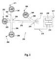
- Fig. 3shows another microfluidic system, as it is for a mass spectroscopic Analysis of fluid substances and / or components contained therein can be used.
- the microfluidic system 210is two at a right angle designed intersecting channels, in turn, with four channel parts 296, 297, 298 and 270 are designed.
- the channel parts 296 and 270are aligned and the channel parts 297 and 298, respectively.
- the channel parts 296, 297, 298 and 270each at an angle of here 90 degrees to each other in a common-seeds Level trained.
- the channel parts 296, 297, 298 and 270intersect at the intersection 295, which has an injection space for the analyte To form a sample.
- a reservoir 233, 221 and 234provided, which in each case with the associated channel part in fluid communication stands.
- These reservoirs 221, 233, 234are each provided with an electrode 271, 283, 284 contacted.
- the reservoir 221takes the to be analyzed sample 241 and the reservoir 234 serves to receive the Waste 254.
- the reservoir 233serves to receive the as a separating substance Serving buffer 253.
- ESIelectro-spray interface
- the Voltage generator 219For the purpose of a mass spectroscopic analysis is using the Voltage generator 219 generates a so-called "ESI" voltage, the Generation of the electric spray 215 is used.
- the ESI voltageis usually from User adjustable to put them on a specific mass spectrometer and the to adapt to given conditions. Thus, this voltage varies from device to device, or depending on the conditions of use.
- the Voltage generator 219By means of by the Voltage generator 219 is generated at the end of the electric field Channel 270 exiting fluid toward the sensor 218 of the mass spectrometer accelerated. In this way, an electro-spray 215 can be generated which is a mass spectroscopic analysis of the sample to be analyzed allows.
- Electrode 216 at the measuring point for certain electrical parameters created that is of interestit is proposed a Reference channel 299 provided at the point of interest in the Working channel 270 opens and at its opposite end then in a known manner, a reservoir 237 for receiving a measuring liquid 294th is arranged. With the reservoir 237 is also known manner a Measuring electrode 300 is contacted. It is understood that in particularly favorable Embodiment of the invention for the aforementioned purposes already existing Channels and electrodes can be meaningfully exploited. By use such reference channels forming a virtual electrode at the measurement site Consequently, the disadvantages described above can be avoided.
- the microfluidic system 310 shown in FIG. 4represents a partial section of the Microfluidic system 10 according to FIG. 1 and is otherwise similar to the Microfluidic system 210 shown in FIG. 3 designed channel parts.
- the Microfluidic system 310comprises a connection channel 401 which is connected at one end to the Reservoir 333 is fluidly connected, in which serving as separation substance buffer 353rd is included.
- the connecting channel 401opens at the injection site 365 in an injection room. In this injection room, three more channels open, namely, the two side channels 402 and 403 and here as a separation channel serving working channel 370.
- the working channel 370has at its from the Injection point 365 facing away from a reservoir 335 for receiving the waste 355 on.
- each reservoir 321, 322, 334 and the reservoirs 332, 336, 337fluidly arranged.
- Each reservoir 321, 322, 332, 333, 334, 335, 336, 337is in each case contacted with an electrode 371, 372, 382, 383, 384, 385, 386, 397, for input and / or output electrical characteristics, in particular electrical Serve voltage and / or electrical current.
- the samples 341, 342 and 352 and in the reservoir 337is in this case the Reference liquid 394 was added. It is understood that the reservoir 337 in the generally also usable for receiving a sample liquid.
- microfluidic chipsA Big Advantage of Being Open Networks by interconnected fluid-channeled microfluidic systems, In particular, microfluidic chips is that this is a particularly economical Working with a variety of different samples in a small space enable. It is therefore at electrophoretic and / or electroosmotic Separation analyzes usual that parallel to the separation analysis concerning a specific Sample substance, for example, the sample 341, the next operation or the subsequent separation analysis is already prepared so that in a so-called Preinjection phase, the next sample, for example, the sample 352, to an in As close as possible to the injection point 365 arranged transition point 367 "is pulled".
- this channel partis also designed as a working channel 400.
- the reference channel 399is provided at the end remote from the transition point 367 the reservoir 337 with the reference liquid 394 or another sample is arranged.
- a kind of virtual electrodecan be created at the transition point 367. This is achieved by first regulating the electrical current (I 2 ) to zero at the second electrode 397 functioning as a sensor, so that in this way the electrical voltage (U 2 ) at the second electrode 397 is measured or detected can be.
- an arbitrary electrical voltage (U 1 )is applied to the first electrode 382, which is contacted with the reservoir 352 receiving the sample 352.
- the electrical voltage (U 1 ) at the first electrode 382is regulated to a voltage value which is increased by a predetermined voltage value of, for example, 200 volts.
- a predetermined voltage valuefor example, 200 volts.
- that voltage differenceis selected as a predetermined voltage value, which has proven useful or necessary in preliminary tests for the movement of the fluid in question or the components contained therein in the intended time.
- the desired voltage differencecan be kept essentially constant by means of the regulator according to the invention in accordance with the exemplary embodiment shown in FIG. 2, again by changing the electrical voltage (U 2 ) is measured on the second electrode 397 formed as a measuring electrode and by proceeding according to the steps described above.
- the target current (I 3 -Soll) at the third electrode 386becomes the sum of the current (I 1 ) measured at the first electrode 382 and a predetermined current (I 4 ) (arrow 404) also calculated as the fourth channel called side channel 402.
- the current intensity (I 3 ) at the third electrode 386is controlled to the value of the previously calculated desired current intensity (I 3 -Soll), by means of a further, not shown in the figures controller.
- the first electrode 382also serves as a measuring electrode for measuring the electrical current intensity (I 1 ).
Landscapes
- Health & Medical Sciences (AREA)
- Chemical & Material Sciences (AREA)
- Life Sciences & Earth Sciences (AREA)
- Molecular Biology (AREA)
- General Health & Medical Sciences (AREA)
- Chemical Kinetics & Catalysis (AREA)
- Analytical Chemistry (AREA)
- Physics & Mathematics (AREA)
- Electrochemistry (AREA)
- Biochemistry (AREA)
- General Physics & Mathematics (AREA)
- Immunology (AREA)
- Pathology (AREA)
- Dispersion Chemistry (AREA)
- Clinical Laboratory Science (AREA)
- Hematology (AREA)
- Physical Or Chemical Processes And Apparatus (AREA)
- Automatic Analysis And Handling Materials Therefor (AREA)
Abstract
Description
Translated fromGermanMikrofluid-Systeme sind aus der US 5,965,001, der US 5,800,690 sowie aus derZeitschrift Electrophoresis (2000), Seite 100 bis 106 sowie Seite 107 bis 115vorbekannt. Der Inhalt dieser Dokumente wird an dieser Stelle zu beliebigenZwecken in vollem Umfang aufgenommen, da in diesen Unterlagen wichtigeMerkmale, insbesondere betreffend die konstruktive und werkstoffliche Ausbildungderartiger Mikrofluid-Systeme sowie betreffend mögliche Verfahren für den Transportund die Führung von Fluiden und/oder darin enthaltenen Bestandteilen in derartigenMikrofluid-Systemen offenbart sind, also von Merkmalen, für die einzeln oder inKombination untereinander, in Kombination mit den in dieser Anmeldung zusätzlichoffenbarten Merkmalen Schutz beansprucht wird.Microfluidic systems are known from US 5,965,001, US 5,800,690 and fromJournal Electrophoresis (2000), pages 100 to 106 and pages 107 to 115previously known. The content of these documents becomes arbitrary at this pointPurposes, as important in these documentsFeatures, in particular concerning the structural and material trainingSuch microfluidic systems as well as possible methods for transportand the guidance of fluids and / or components contained therein in suchMicrofluidic systems are disclosed, so of features for which individually or inCombination with each other, in combination with the additional in this applicationdisclosed features protection is claimed.
Von besonderem Interesse sind derartige Mikrofluid-Systeme für Anwendungen imBereich der Elektroosmose und/oder der Elektrophorese, wobei aus Gründen derÖkonomie und einem entsprechend größeren Anwendungsspektrum bevorzugt einoffenes Netzwerk von miteinander fluidverbundenen Miniaturkanälen eingesetzt wird.Dabei wird die Bewegung der individuellen Flüssigkeiten oder darin enthaltenerZellen, Organismen oder Bestandteile, wie Partikel oder Ionen oder neutrale Stoffe,bislang meist durch Ausübung elektrischer oder elektrokinetischer Kräfte, insbesonderedurch elektrische Spannung, elektrischen Strom, elektrische Leistung oderdurch andere elektrische Parameter kontrolliert. Diese elektrischen Kenngrößenwerden üblicherweise mittels geeigneter Elektroden in das Fluid eingeleitet, die amjeweiligen Ende der sich teilweise kreuzenden Kanäle mit sogenannten Reservoirskontaktiert sind, welche wiederum in Fluidverbindung mit den einzel nen Mikrokanälenstehen.Of particular interest are such microfluidic systems for applications in theRange of electroosmosis and / or electrophoresis, for reasons ofEconomics and a correspondingly wider range of applications preferredopen network of fluid-connected miniature channels is used.In doing so, the movement of the individual fluids or contained thereinCells, organisms or constituents, such as particles or ions or neutral substances,so far mostly by applying electrical or electrokinetic forces, in particularby electrical voltage, electric current, electric power orcontrolled by other electrical parameters. These electrical parametersare usually introduced by means of suitable electrodes in the fluid, the onrespective end of the partially crossing channels with so-called reservoirswhich in turn are in fluid communication with the individual NEN microchannelsstand.
Ein Problem bei der Anwendung von elektrokinetischen Kräften unter Verwendungvon Elektroden ist es, daß diese nicht unmittelbar in bzw. an den Mikrokanälen desMikrofluid-Systems eingesetzt werden können, da es an den Elektroden häufig zueiner unerwünschten Gasblasenbildung kommt. Diese Gasblasen können jedoch in den miniaturisierten Kanälen zu einer Erhöhung des wirksamen Widerstandes bis hinzu einem unendlich großen wirksamen Widerstand führen. Aus diesen Gründenwerden die Elektroden üblicherweise mit Reservoirs verbunden, die ein vergleichsweisegroßes Fluid-Volumen aufnehmen können und die gegenüber der Geometrieder Miniaturkanäle deutlich größere Abmaße aufweisen. Dadurch ist jedoch derEinsatz der Elektroden auf das jeweilige Ende der Miniaturkanäle begrenzt. Für eineexakte und reproduzierbare Versuchsdurchführung sind jedoch häufig die elektrischenParameter an den Kreuzungspunkten bzw. denjenigen Übergangsbereichenvon Interesse, an denen die einzelnen Mikrofluidkanäle ineinander einmünden.A problem with the application of electrokinetic forces usingof electrodes is that they are not directly in or on the microchannels of theMicrofluidic system can be used as it is common on the electrodes tooan undesirable gas bubble formation comes. However, these gas bubbles can be inthe miniaturized channels to increase the effective resistance uplead to an infinite effective resistance. For these reasonsThe electrodes are usually connected to reservoirs, which is a comparativelycan absorb large volumes of fluid and those opposite the geometrythe miniature channels have significantly larger dimensions. This, however, is theUse of the electrodes limited to the respective end of the miniature channels. For onehowever, exact and reproducible test procedures are often the electrical onesParameters at the crossing points or those transition areasof interest, in which the individual microfluidic channels merge into one another.
Es ist Aufgabe der Erfindung, ein verbessertes Mikrofluid-System zu schaffen.It is an object of the invention to provide an improved microfluidic system.
Diese Aufgabe wird durch die Merkmale der unabhängigen Ansprüche gelöst.Vorteilhafte Ausführungsformen werden durch die Merkmale der Unteransprüchedargestellt.This object is solved by the features of the independent claims.Advantageous embodiments are characterized by the features of the subclaimsshown.
Dadurch, daß wenigstens ein Meßfühler vorgesehen ist, und der Regler mit demMeßfühler und der Einrichtung zur Veränderung der treibenden Kraft und/oder derdadurch beeinflußbaren Kenngröße gekoppelt ist, wird ein besserer Durchgriff aufdas jeweilige Betriebsverhalten des einzelnen Mikrofluid-Systems möglich, indem aufinnere und/oder äußere Störgrößen eine entsprechende Regelung der treibendenKraft und/oder dadurch beeinflußbarer Kenngrößen und unter Anwendung jeweilsgeeigneter Algorithmen eine dynamische Sollwertanpassung realisiert werden kann.Auf diese Weise läßt sich auch ein breiteres Anwendungs- und Einsatzspektrumermöglichen, weil sich das System beispielsweise auf anwenderspezifische Fehlerbzw. bei einer Variation von vom Anwender bevorzugten Proben quasi von selbstanpassen kann.Characterized in that at least one sensor is provided, and the controller with theSensor and the device for changing the driving force and / or theThis is influenced influenceable parameter is a better penetrationthe respective operating behavior of the individual microfluidic system possible byinternal and / or external disturbances a corresponding regulation of the drivingForce and / or thereby influenceable characteristics and using eachappropriate algorithms dynamic setpoint adjustment can be realized.In this way, a wider range of applications and applications can beFor example, because the system relies on user-specific errorsor in a variation of user-preferred samples virtually by itselfcan adapt.
Dadurch, daß mit dem Arbeitskanal wenigstens ein, in diesen einmündenderMeßkanal fluidverbunden ist, der mit dem Meßfühler gekoppelt ist, lassen sichinsbesondere an den bisher für den Einsatz von Elektroden ungeeigneten Kanal-Kreuzungsstellenbzw. denjenigen Stellen, an denen ein oder mehrere Kanäle in einoder mehrere andere Kanäle einmünden, geeignete Meß- und/oder Eingriffsmöglichkeitenfür die Ein- und/oder Ausleitung elektrischer Kenngrößen schaffen, indem dort quasi "virtuelle" Elektroden zur Verfügung gestellt werden. Zu diesem Zwecke kannsowohl ein an der gewünschten Stelle bereits existierender Miniaturkanal ausgenutztwerden, oder kann das Design des jeweiligen Mikrofluid-Systems in einfacher Weisedadurch geändert werden, daß ein weiterer Miniaturkanal vorgesehen wird, der ander gewünschten Meßstelle in einen oder in mehrere vorhandene Kanäle einmündetund der an seinem gegenüberliegenden Ende in Fluidverbindung mit einemgeeigneten Reservoir steht, das wiederum mit einer Elektrode kontaktiert ist.Characterized in that with the working channel at least one, in this einmündenderMeasuring channel is fluidly connected, which is coupled to the sensor, can beespecially at the previously unsuitable for the use of electrodes channel crossing pointsor those places where one or more channels in aor several other channels, suitable measuring and / or intervention optionscreate for the introduction and / or elimination of electrical characteristics by therevirtually "virtual" electrodes are provided. For this purpose canboth exploited at the desired location already existing miniature channelor can the design of the respective microfluidic system in a simple mannerbe changed in that a further miniature channel is provided to thethe desired measuring point opens into one or more existing channelsand at its opposite end in fluid communication with asuitable reservoir, which in turn is contacted with an electrode.
Zweckmäßigerweise ist das Mikrofluid-System mit einem offenen Netzwerk vonmiteinander fluidverbundenen Kanälen ausgebildet, wobei wenigstens drei,vorzugsweise vier der Kanäle in einen gemeinsamen, insbesondere punktartigausgebildeten Kanalraum einmünden, wobei einer der Kanäle als Meßkanal fungiert.Im Rahmen einer derartigen Drei- bzw. Vierkanaltechnik lassen sich besondersgünstig über den Meßkanal bzw. die Meßkanäle regelbare Stoffflüsse erreichen,welche die Anwendung von ökonomisch handhabbaren Regelalgorithmen ermöglichenund die ein erheblich verbreitetes Anwendungs- und Einsatzspektrum derartigerMikrofluid-Systeme ermöglichen.Conveniently, the microfluidic system is with an open network offormed fluidly interconnected channels, wherein at least three,preferably four of the channels in a common, in particular point-likeopen trained channel space, wherein one of the channels acts as a measuring channel.In the context of such a three- or four-channel technology can be particularlyreach controllable substance flows via the measuring channel or the measuring channels,which allow the application of economically manageable control algorithmsand the a widely used application and application spectrum of suchEnable microfluidic systems.
Es ist besonders zweckmäßig, wenn alle Elektroden sowohl als Arbeitselektrode alsauch als Meßelektrode einsetzbar sind bzw. eingesetzt werden. Dadurch wird dasAnwendungs- und Einsatzspektrum bestehender Mikrofluid-Systeme vorteilhafterweitert, in dem an beliebigen, mit Arbeitselektroden versehenen Kanalstellennunmehr auch die für eine günstige Regelung der Stoffflüsse geeigneten Meßfühlerzur Verfügung stehen.It is particularly useful if all the electrodes are used both as a working electrodecan also be used or used as a measuring electrode. This will do thatApplication and application spectrum of existing microfluidic systems advantageousextended, in any, provided with working electrodes channel pointsnow also suitable for a favorable control of the material flow sensorbe available.
Vorteilhafterweise regelt der Regler die treibende Kraft und/oder die dadurchbeeinflußbare Kenngröße derart, daß diese insbesondere unabhängig von innerenund/oder äußeren Störgrößen im wesentlichen konstant gehalten wird bzw. werden,so daß eine größere Betriebssicherheit und ein größeres Anwendungs-Einsatzspektrumermöglicht sind. Mit "konstant" ist im Rahmen der Offenbarungdieses Schutzrechts nicht nur ein über der Zeit gleichbleibender absoluter Kennwertgemeint, sondern eine beliebige Kennwertfunktion über der Zeit, also beispielsweiseein "Gradient" oder eine "Rampe", die aber durch die erfindungsgemäße Regelunginvariant in Reaktion auf innere oder äußere Störeinflüße gehalten wird.Advantageously, the controller regulates the driving force and / or therebyinfluenceable characteristic such that it is particularly independent of internaland / or external disturbances are kept substantially constant,so that greater reliability and a wider range of applicationare possible. With "constant" is within the scope of the disclosureThis protection right is not just a constant absolute value over timemeant, but any characteristic function over time, so for examplea "gradient" or a "ramp", but by the inventive controlis kept invariant in response to internal or external disturbances.
Von besonderem Vorteil ist es, wenn der Regler die treibende Kraft und/oder diedadurch beeinflußbare Kenngröße derart regelt, daß der Gradient der treibendenKraft und/oder der Gradient der durch die treibende Kraft beeinflußbaren Kenngrößeüber einen bestimmten Abschnitt des Arbeitskanals, insbesondere unabhängig voninneren und/oder äußeren Störgrößen, im wesentlichen konstant gehalten wird bzw.werden. Auf diese Weise läßt sich in dem Arbeitskanal eine im wesentlichenkonstante Geschwindigkeit bzw. ein im wesentlichen konstanter Durchfluß des Fluidsund/oder darin enthaltener Bestandteile erreichen, was für viele Anwendungen,insbesondere für Anwendungen im Bereich der Trennanalyse interessant ist.It is particularly advantageous if the controller is the driving force and / or thecharacterized controllable characteristic such that the gradient of the drivingForce and / or the gradient of the influenceable by the driving force characteristicover a certain section of the working channel, in particular independently ofinternal and / or external disturbances, is kept substantially constant orbecome. In this way, can be in the working channel a substantiallyconstant speed or a substantially constant flow of the fluidand / or constituents contained therein, which is the case for many applications,especially interesting for applications in the field of separation analysis.
Es ist ferner vorteilhaft, wenn der Regler die treibende Kraft und/oder die dadurchbeeinflußbare Kenngröße dergestalt regelt, daß eine im wesentlichen konstante odervorbestimmte joulesche Verlustleistung erreicht wird, so daß die in dem Fluidfadendes Arbeitskanals auftretende Temperatur konstant gehalten wird oder dieTemperaturerhöhung bestimmbar ist und folglich einer weiteren rechnerischenAuswertung zuführbar ist. Dabei ist es zweckmäßig, wenn die Regelung bzw. dieIdentifikation der Probenbestandteile abhängig von der Eigenmobilität im Zusammenhangmit der am Trennkanal angelegten Differenzspannung erfolgt, um beiauftretenden Leitfähigkeitsveränderungen eine Identifikation der Probenbestandteileüber deren Eigenmobilität zu ermöglichen.It is also advantageous if the controller is the driving force and / or therebycontrollable characteristic such that a substantially constant orpredetermined Joule power dissipation is achieved so that in the fluid threadof the working channel occurring temperature is kept constant or theTemperature increase is determinable and therefore another computationalEvaluation can be fed. It is useful if the scheme or theIdentification of the sample components depending on the own mobility in contextwith the voltage applied to the separation channel differential voltage to atoccurring conductivity changes an identification of the sample componentsto allow about their own mobility.
Von besonderem Vorteil ist es, wenn bei dem als offenes Netzwerk von miteinanderfluidverbundenen Kanälen ausgebildeten Mikrofluid-System mehrere Kanäle in einengemeinsamen, insbesondere punktartig ausgebildeten Kanalraum einmünden, wobeiwenigstens einer der Kanäle als Meßkanal fungiert, und wobei die Kanäle an ihremjeweiligen, von dem Kanalraum entfernten Ende, jeweils mit einer Elektrode zurAusübung eines elektrischen Feldes auf das Fluid kontaktiert sind, und wobei dieElektroden mit elektrischem Strom und/oder elektrischer Spannung beaufschlagbarsind, und wobei einem ersten Kanal eine erste Elektrode und einem zweiten Kanaleine zweite Elektrode zugeordnet ist, gekennzeichnet durch die folgenden Schritte:
Auf diese Weise lassen sich derartige Mikrofluid-Systeme bei Anwendungen auf demGebiet der Kapillarelektrophorese, der Flüssigkeitskromatographie und beichemischen Reaktionen, insbesondere bei DNA/RNA-Assays oder Protein-Assaysmit einer höheren Betriebssicherheit gegenüber inneren und/oder äußerenStörgrößen und bei einem erweiterten Anwendungs- und Einsatzspektrum einsetzen,die auch den aktuellen und den zukünftigen Anwenderbedürfnissen bei gleichbleibendhoher Qualität der Analysenergebnisse auch über einen langen Zeitraumgenügen.In this way, such microfluidic systems can be used in applications on theArea of capillary electrophoresis, liquid chromatography andchemical reactions, especially in DNA / RNA assays or protein assayswith a higher operational safety against internal and / or externalUse disturbance variables and in an extended range of applications and applications,which also meets current and future user needshigh quality of analysis results even over a long period of timesuffice.
Dabei ist es ferner zweckmäßig, daß bei dem als offenes Netzwerk von miteinanderfluidverbundenen Kanälen ausgebildeten Mikrofluid-System wenigstens vier Kanälein einen gemeinsamen, insbesondere punktartig ausgebildeten Kanalraumeinmünden, wobei wenigstens einer der Kanäle als Meßkanal fungiert, und wobeiwenigstens drei der Kanäle an ihrem jeweiligen, von dem Kanalraum entferntenEnde, jeweils mit einer Elektrode zur Ausübung eines elektrischen Feldes auf dasFluid kontaktiert sind, und wobei die Elektroden mit elektrischem Strom und/oderelektrischer Spannung beaufschlagbar sind, und wobei dem ersten Kanal eine ersteElektrode. dem zweiten Kanal eine zweite Elektrode und dem dritten Kanal eine dritteElektrode zugeordnet ist, gekennzeichnet durch die folgenden Schritte:
Auf diese Weise lassen sich die vorstehend bezeichneten Vorteile auch in hochkomplexen,auf der Vierkanaltechnik basierenden Mikrofluid-Systemen unter Anwendungeines einfachen mathematischen Algorithmus erreichen.In this way, the advantages described above can also be used in highly complex,on the four-channel technology-based microfluidic systems usingachieve a simple mathematical algorithm.
Gemäß der Erfindung führen bei dem als offenes Netzwerk von miteinanderfluidverbundenen Kanälen ausgebildeten Mikrofluid-System wenigstens zwei Kanälezu einem gemeinsamen ESI- (Electro -Spray-Interface) -Punkt, wobei wenigstenszwei der Kanäle an ihrem jeweiligen, von dem gemeinsamen Kanalraum entferntenEnde, jeweils mit einer Elektrode zur Ausübung eines elektrischen Feldes auf dasFluid kontaktiert sind, und wobei die Elektroden mit elektrischem Strom und/oderelektrischer Spannung beaufschlagbar sind, und wobei die Summe des elektrischenStromes in dem gesamten Mikrofluid-System dergestalt geregelt wird, daß gemäßdem Kirchhoffschen Gesetz ein bestimmter ESI-Reststrom verbleibt.According to the invention lead in the open network of each otherfluid-connected channels formed microfluidic system at least two channelsto a common ESI (electrospray interface) point, where at leasttwo of the channels at their respective, away from the common channel spaceEnd, each with an electrode for applying an electric field on theFluid are contacted, and wherein the electrodes with electric current and / orelectrical voltage can be acted upon, and wherein the sum of the electricCurrent is regulated in the entire microfluidic system such that according tothe Kirchhoff law remains a certain ESI residual current.
Vorstehende Merkmale tragen sowohl einzeln als auch in Kombination untereinanderzu einem Mikrofluid-System bzw. einem Verfahren zum Transport und der Führungeines Fluids und/oder darin enthaltener Bestandteile in einem derartigen Mikrofluid-Systembei, das ein breiteres Anwendungs- und Einsatzspektrum und eineverringerte Empfindlichkeit gegenüber inneren und/oder äußeren Störgrößen undfolglich eine größere Betriebssicherheit ermöglicht.The above features carry each other individually as well as in combinationto a microfluidic system or a method of transport and guidancea fluid and / or components contained therein in such a microfluidic systemthat offers a wider range of applications and applications and areduced sensitivity to internal and / or external disturbances andthus allowing greater reliability.
Weitere Merkmale, Gesichtspunkte und Vorteile der Erfindung sind dem nachfolgenden,anhand der Figuren abgehandelten Beschreibungsteil entnehmbar, in dembevorzugte Ausführungsbeispiele der Erfindung beschrieben sind.Further features, aspects and advantages of the invention are the following,With reference to the figures negotiated description part removable, in thePreferred embodiments of the invention are described.
Es zeigen:
- Fig. 1
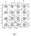
- ein erfindungsgemäßes Mikrofluid-System in Form eines Mikrofluid-Chips mit insgesamt 16 Reservoirs zur Aufnahme von fluiden Substanzen,wobei diese Reservoirs mit einem offenen Netzwerk von Mikrokanälenin Fluidverbindung stehen und mit einem als Arbeitskanal dienendenTrennkanal, das insbesondere in der elektrophoretischenFlüssigkeitsanalyse einsetzbar ist;
- Fig. 2
- eine schematische Darstellung eines einfach aufgebauten Mikrofluid-Systems gemäß der Erfindung, mit Darstellung der für die Steuerungund Regelung der hier elektrischen bzw. elektrokinetischen Prozesseerforderlichen Einrichtungen;
- Fig. 3
- ein weiteres Mikrofluid-System gemäß einer bevorzugten Ausführungsformder Erfindung unter Verwendung eines Referenzkanals und unterAusbildung einer virtuellen Elektrode am Beispiel einermassenspektrometrischen Analysenanwendung;
- Fig. 4
- ein weiteres Mikrofluid-System mit einem Netzwerk von untereinanderfluidverbundenen Mikrokanälen und unter Verwendung eines mit einerMeßelektrode kontaktierten Referenzkanals zur Erläuterung einerbesonders vorteilhaften Verfahrensweise.
- Fig. 1
- a microfluidic system according to the invention in the form of a microfluidic chip with a total of 16 reservoirs for receiving fluid substances, which reservoirs are in fluid communication with an open network of microchannels and with a separation channel serving as a working channel, which can be used in particular in electrophoretic fluid analysis;
- Fig. 2
- a schematic representation of a simply constructed microfluidic system according to the invention, with representation of the necessary for the control and regulation of the electrical or electro-kinetic processes here;
- Fig. 3
- a further microfluidic system according to a preferred embodiment of the invention using a reference channel and forming a virtual electrode using the example of a mass spectrometric analysis application;
- Fig. 4
- Another microfluidic system with a network of interconnected fluidly connected micro-channels and using a contacted with a measuring electrode reference channel to explain a particularly advantageous procedure.
Das in Fig. 1 gezeigte Mikrofluid-System 10 beinhaltet einen Mikrofluid-Chip 11.Dieser umfaßt das Substrat 12, in das hier insgesamt sechzehn Reservoirs 21 bis 36zur Aufnahme von diversen fluiden Substanzen aufgenommen sind. Dabei sind zwölfReservoirs 21 bis 32 zur Aufnahme der Proben 41 bis 52, ein Reservoir 33 zurAufnahme eines als Trennmedium dienenden Puffers 53 sowie die mit etwas Puffervorgefüllten Reservoirs 34, 35, 36 zur Aufnahme von Abfall 54, 55, 56 vorgesehen.Die Reservoirs 21 bis 36 sind untereinander durch Mikro-Kanäle fluidverbunden, diemiteinander ein offenes Netzwerk ausbilden. Dies bedeutet, daß jedes derReservoirs 21 bis 36 in Fluidverbindung mit jedem anderen Reservoir steht. Die indie Reservoirs 21 bis 32 mündenden Kanäle münden wiederum im Bereich einerÜbergangsstelle 66 in einen einzigen Kanal, der sich im Bereich einer Übergabestelle68 in zwei Kanäle aufteilt. Der erste Kanal dieser beiden Kanäle mündet in das Reservoir 34, das zur Aufnahme des Abfalls 54 dient. Der zweite Kanal dieser beidenKanäle mündet in den Injektionsraum der Injektionsstelle 65, die wie hier gezeigt alszwei sich kreuzende Kanäle mit insgesamt vier Kanal-Teilen gestaltet sein kann. Dortmündet auch der Kanal 61 ein. Dieser mündet an seinem von dem Injektionsraumabgewandten Ende in das Reservoir 33. Dieses dient zur Aufnahme des alsTrennsubstanz fungierenden Puffers 53. Der Einmündungsstelle des Kanals 61 inden Injektionsraum gegenüberliegend mündet der Arbeitskanal 70. Dieser dient zureigentlichen Trennung der zu analysierenden Substanzen und mündet wiederum indas Reservoir 35 zur Aufnahme des Abfalls 55 nachdem die analytische xxxDetektionstelle69 passiert wurde. Der der Injektionsstelle 65 zugeordnete Injektionsraum istim Ausführungsbeispiel als Kreuzungspunkt der vorstehend beschriebenen vierKanal-Teile gestaltet, die in dieser Ausführung jeweils um einen Winkel von 90 Gradversetzt zueinander in einer gemeinsamen Ebene angeordnet sind, wobei die sichjeweils gegenüberliegenden Kanalteile in dem hier gezeigten Fall zueinanderfluchtend angeordnet sind.The
Jedes Reservoir 21 bis 36 ist mit einer Elektrode 71 bis 86 kontaktiert. Diese dienenzur Ein- bzw. Ausleitung von elektrischer Spannung und/oder elektrischem Stromund können gemäß der Erfindung zugleich als Meßelektrode dienen. Mit deren Hilfekönnen dem aktuellen Betriebsverhalten des Mikrofluid-Systems 10 zugeordneteelektrische Parameter erfaßt und einem Regler zur Regelung der treibenden Kraftund/oder einer dadurch beeinflußbaren Kenngröße zugeführt werden. Im Ausführungsbeispielsind als treibende Kraft elektrokinetische Kräfte vorgesehen, welchedurch Einleitung bzw. Ausübung von elektrischen Spannungen über die Elektroden71 bis 86 auf die jeweiligen Fluide 41 bis 56 eingeleitet bzw. übertragen werdenkönnen, so daß sich die Fluide bzw. darin enthaltene Bestandteile in der vomAnwender gewünschten Richtung und Geschwindigkeit durch die ein offenesNetzwerk bildenden Miniaturkanäle bewegen können.Each reservoir 21 to 36 is contacted with an
Das in Fig. 2 teilweise schematisch gezeigte Mikrofluid-System 110 ist besonderseinfach gestaltet. Diese Figur dient auch zur Darstellung der für die Steuerung undRegelung der das Fluid bzw. die darin enthaltenen Bestandteile treibenden Kraftund/oder der dadurch beeinflußbaren Kenngrößen. Das Mikrofluid-System 110 weistden einen Arbeitskanal 170 auf, in dem das Fluid 141 und/oder darin enthaltene Bestandteile vermittels einer treibenden Kraft, hier eines durch die Spannungsquelle188 erzeugten elektrischen bzw. elektrokinetischen Feldes in Richtung (Pfeil 113)des Arbeitskanals 170 bewegbar sind. An den jeweiligen Enden des Arbeitskanals170 sind die Reservoirs 121 und 135 angeordnet, die mit dem Arbeitskanal 170 inFluidverbindung stehen. Jedes Reservoir 121, 135 ist jeweils mit einer Elektrode 171bzw. 185 zur Ein- bzw. Ausleitung von elektrischen Kenngrößen kontaktiert. UnterAnlegung einer elektrischen Spannung an die Elektrode 171 kann das Fluid 141 bzw.können die darin enthaltenen Bestandteile in Richtung (Pfeil 113) des Arbeitskanals170 durch diesen hindurchbewegt werden und kann bzw. können schließlich anseinem anderen Ende als Abfall 155 in das Reservoir 135 gelangen. Bei derTrennanalyse in dem Arbeitskanal 170 ist es von besonderer Wichtigkeit, daß dasFluid 141 bzw. die daran enthaltenem Bestandteile sich mit einer im wesentlichenkonstanten Geschwindigkeit durch den Arbeitskanal 170 bewegen, um einemöglichst exakte Analyse vornehmen zu können. Ein charakteristischer Parameterzur Identifikation eines Probenbestandteiles ist die Eigenmobilität. Diese Stoffkonstanteführt im Zusammenhang mit den Betriebsparametern Feldstärke undViskosität des Trennmediums zu einer charakteristischen Geschwindigkeit. Da dieViskosität des Trennmediums aber stark temperaturabhängig ist, ergibt sich dasBedürfnis, die der Flüssigkeit im Trennkanal zugeordnete Temperatur exakt zubestimmen oder zu beeinflussen. Während die Außenfläche des Mikrofluid-Chips mitgeeigneten Mitteln auf eine gewünschte Temperatur gebracht werden kann, ist durchdas Auftreten der "joule-schen Verlustleistung" im Innern des Fluids eine erhöhteTemperatur gegeben, die aber auf Grund der miniaturisierten Geometrie nichtgemessen werden kann. Zu diesem Zwecke ist es vorteilhaft, die auftretendeVerlustleistung unabhängig von inneren und äußeren Störeinflüssen konstant zuhalten. Reproduzierbare Betriebsbedingungen, und damit Ergebnisse, sind somiterreichbar. Abhängig vom wirksamen Widerstand im Arbeitskanal und/oder derLeitfähigkeit des Fluids 141 kann sich die auftretende Verlustleistung ändern, mit derFolge, daß bei Anlegung einer im wesentlichen konstanten Spannung an denElektroden 171 und 185, gemäß dem Stand der Technik, sich abhängig von deninneren und/oder äußeren Störgrößen im Innern des auch als Fluidfaden bezeichnetenFluidstromes eine gegenüber dem Sollwert veränderte Temperatur einstellt, sodaß sich über die Viskosität die Momentangeschwindigkeit der Probenbestandteileim Trennkanal abhängig von den inneren und/oder äußeren Störgrößen ausbildet.The
Dies kann zu entsprechend unterschiedlichen Wanderungsgeschwindigkeiten desFluids 141 und/oder darin enthaltener Bestandteile führen, so daß entsprechendeFehler bei der Analyse, hier im wesentlichen bei der Identifikation, auftreten können.This may correspond to different migration speeds of the
Zur Vermeidung der vorstehend beschriebenen Nachteile ist die Elektrode 185 alsMeßelektrode, d.h. als Meßfühler zur Messung einer dem Fluid 141 zugeordnetenbzw. an das Fluid 141 gekoppelten und im Bereich des Fluids 141 ableitbarenMeßgröße, hier des elektrischen Stromes, vorgesehen. Mit dem Meßfühler 185 istder Regler 192, hier über elektrische Leitungen, gekoppelt. Dieser Regler 192gehorcht einem vorbestimmten mathematischen Algorithmus 193 und kann auch alsprogrammierbarer Regler gestaltet sein. Der Regler 192 ist seinerseits mit einerEinrichtung zur Veränderung der treibenden Kraft 189, hier der elektrischenSpannung gekoppelt, welche ein Stellglied ausbildet. Die Einrichtung zur Veränderungder treibenden Kraft 189 ist mit der Spannungsquelle 188 gekoppelt, welche dienotwendige elektrische Spannung bzw. das notwendige elektrische Feld liefert. Mitder Einrichtung zur Veränderung der treibenden Kraft 189 ist wiederum eineSteuereinrichtung 191 zur Steuerung der Einrichtung zur Veränderung dertreibenden Kraft nach bestimmten voreingestellten Parametern verbunden. Dabeikann es sich um die gemäß dem Stand der Technik in einem sogenannten "Skript"festgelegten Parameter handeln. Diese können auch in einer Speichereinheit,beispielsweise einem RAM bzw. ROM abgelegt sein. Die Einrichtung zur Veränderungder treibenden Kraft 189 ist ferner mit einer Reglereinrichtung 190 zurBereitstellung von stabilisierten, d.h. im wesentlichen konstanten elektrischenSpannungen oder Strömen gekoppelt, die wiederum mit der Elektrode 171 elektrischgekoppelt ist. Der Regler 192 erhält von der Regeleinrichtung 190 den aktuellenStatus, welcher mit Hilfe des vorbestimmten mathematischen Algorithmus 193 mitKenntnis des gemessenen Stromes in eine aktuelle Abweichung der Verlustleistungund damit in einen Korrekturwert umgerechnet werden kann. Dieser Korrekturwertwird zur Steuerung der Einrichtung 189 zur Veränderung der treibenden Kraftverwendet. Auf diese Weise läßt sich ein sich an das aktuelle Betriebsverhalten desMikrofluid-Systems 110 anpassender überlagerter Regelkreis schaffen, mit dem esmöglich ist, die auftretende Verlustleistung und damit die im Fluidfaden desArbeitskanals 170 auftretende Temperaturerhöhung unabhängig von innerenund/oder äußeren Störgrößen im wesentlichen konstant zu halten.To avoid the disadvantages described above, the
Die Identifikation der Probenbestandteile kann nun in Erwartung der konstantenTemperaturverhältnisse und in Kenntnis der meßbaren Spannungdifferenz amTrennkanal durch ein Zeitfenster erfolgen. Dieses Zeitfenster, gerechnet ab Zeitpunktder Einspritzung, ergibt sich aus der entsprechenden Mobilität im elektrischen Feldüber die Entfernung im Trennkanal vom Einspritzpunkt bis zum Ort der Detektion.The identification of the sample components can now be expected in the constantTemperature conditions and in knowledge of the measurable voltage difference onSeparation channel through a time window. This time window, calculated from the timeInjection, resulting from the corresponding mobility in the electric fieldover the distance in the separation channel from the injection point to the place of detection.
Die Spannungsquelle 188, die Einrichtung zur Veränderung der treibenden Kraft 189,die Steuereinrichtung 191 und die Reglereinrichtung 190 bilden die Spannungsversorgungseinheit187. Es versteht sich, daß eine derartige Spannungsversorgungseinheit,zumindest die Einrichtung zur Veränderung der treibenden Kraft 189 und dieReglereinrichtung 190, jeder bzw. allen Elektroden 171, 185 auch bei einem mit mehrals zwei Elektroden ausgebildeten Mikrofluid-System, entsprechend den Anwenderbedürfnissenbeliebig mehrfach eingesetzt werden kann. In einem solchen Fall wirddem Regler 192 auch der jeweilige Status von der der Elektrode 185 zugeordnetenRegeleinrichtung 190a zugeführt.The
Die Fig. 3 zeigt ein weiteres Mikrofluid-System, wie es für eine massenspektroskopischeAnalyse von fluiden Substanzen und/oder darin enthaltener Bestandteileeingesetzt werden kann. Das Mikrofluid-System 210 ist mit zwei, sich hier rechtwinkligkreuzenden Kanälen gestaltet, die wiederum mit vier Kanalteilen 296, 297, 298und 270 gestaltet sind. In dem hier gezeigten Fall fluchten die Kanalteile 296 und 270sowie die Kanalteile 297 und 298 jeweils. Im übrigen sind die Kanalteile 296, 297,298 und 270 jeweils in einem Winkel von hier 90 Grad zueinander in einer gemei n-samenEbene ausgebildet. Dabei kreuzen sich die Kanalteile 296, 297, 298 und 270in der Kreuzungsstelle 295, welche einen Injektionsraum für die zu analysierendeProbe bilden. Am Ende der Kanalteile 296, 297 und 298 ist jeweils ein Reservoir 233,221 und 234 vorgesehen, das jeweils mit dem zugehörigen Kanalteil in Fluidverbindungsteht. Diese Reservoirs 221, 233, 234 sind jeweils mit einer Elektrode 271, 283,284 kontaktiert. In dem gezeigten Ausführungsbeispiel nimmt das Reservoir 221 diezu analysierende Probe 241 auf und das Reservoir 234 dient zur Aufnahme desAbfalls 254. Das Reservoir 233 dient zur Aufnahme des als Trennsubstanzdienenden Puffers 253. An dem der Kreuzungsstelle 295 bzw. dem Reservoir 233gegenüberliegenden Ende des als Arbeitskanal ausgebildeten Kanalteils 270 ist ein sogenanntes Elektro-Spray-Interface (ESI) 214 vorgesehen. Dieses ist mit einer nichtnäher gezeigten Düse gestaltet, welche zur Erzeugung eines Elektro-Sprays 215dient. Zum Zwecke einer massenspektroskopischen Analyse wird mit Hilfe desSpannungserzeugers 219 eine sogenannte "ESI"-Spannung generiert, die zurErzeugung des Elektro-Sprays 215 dient. Die ESI-Spannung ist in der Regel vomAnwender einstellbar, um sie auf einen spezifischen Massenspektrometer und diegegebenen Bedingungen anzupassen. Damit schwankt diese Spannung von Gerätzu Gerät, oder je nach den Einsatzbedingungen. Vermittels des durch denSpannungserzeuger 219 erzeugten elektrischen Feldes wird das am Ende desKanals 270 austretende Fluid in Richtung auf den Meßfühler 218 des Massenspektrometersbeschleunigt. Auf diese Weise kann ein Elektro-Spray 215 erzeugt werden,welches eine massenspektroskopische Analyse der zu analysierenden Probeermöglicht. Auch für diese Anwendung ist es erforderlich, daß die Spannungsdifferenzzwischen der Kreuzungsstelle 295 und dem düsenseitigen Ende des Arbeitskanals270 während der Analyse im wesentlichen konstant bleibt. Dies ist jedoch mitden nach dem Stande der Technik bekannten Vorrichtungen und Verfahren in vielenFällen nicht gewährleistet, weil die vorstehend beschriebenen inneren und/äußerenStörgrößen zu einer Veränderung der Spannungsdifferenz und demgemäß zu einerVeränderung der elektrischen Parameter und der Strömung im Arbeitskanal führenkönnen.Fig. 3 shows another microfluidic system, as it is for a mass spectroscopicAnalysis of fluid substances and / or components contained thereincan be used. The
Nun könnte es zu diesem Zwecke naheliegend sein, eine weitere, als Meßelektrodedienende Elektrode im Bereich des düsenseitigen Endes des Arbeitskanalsanzuordnen, um auf diese Weise einen Regelungsmechanismus entsprechend derDarstellung im Zusammenhang mit der Fig. 2 bzw. wie nachstehend im Zusammenhangmit der Fig. 4 beschrieben, zu ermöglichen. In der Praxis ist jedoch der Einsatzvon Meßelektroden an bzw. in den miniaturisierten Mikrokanälen nicht unkritisch undist in vielen Fällen nicht möglich. Denn an den Kontaktstellen können elektrolytischeVorgänge und demzufolge eine Oxidation der Elektroden auftreten, mit der Folgeveränderter Übergangswiderstände. Infolge der veränderten Übergangswiderständeverändern sich jedoch die elektrischen Parameter und dementsprechend verändertsich die Spannungsdifferenz über den Analyseabschnitt in dem Trennkanal.Schließlich können an den Kontaktstellen der Elektroden unerwünschte Blasenauftreten, welche den wirksamen Widerstand in den einen nur sehr kleinen Durchflußquerschnitt aufweisenden Mikrokanälen unsystematisch erhöhen können,bis hin zu einem auf den Wert unendlich ansteigenden wirksamen Widerstand. ZurLösung dieses Problems wird mit der vorliegenden Erfindung quasi eine virtuelleElektrode 216 an derjenigen Meßstelle für bestimmte elektrische Parametergeschaffen, die von Interesse ist. Zu diesem Zwecke wird vorgeschlagen, einenReferenzkanal 299 vorzusehen, der an der interessierenden Meßstelle in denArbeitskanal 270 einmündet und an dessen gegenüber liegendem Ende dann inbekannter Weise ein Reservoir 237 zur Aufnahme einer Meßflüssigkeit 294angeordnet ist. Mit dem Reservoir 237 ist in ebenfalls bekannter Weise eineMeßelektrode 300 kontaktiert ist. Es versteht sich, daß in besonders günstigerAusgestaltung der Erfindung zu den vorgenannten Zwecken bereits bestehendeKanäle und Elektroden sinnvoll ausgenutzt werden können. Durch die Verwendungderartiger Referenz-Kanäle unter Ausbildung einer virtuellen Elektrode am Meßortkönnen folglich die vorstehend beschriebenen Nachteile vermieden werden.Now it might be obvious for this purpose, another, as a measuring electrodeserving electrode in the region of the nozzle-side end of the working channelorder in this way a control mechanism according to theRepresentation in connection with FIG. 2 or as related belowto be described with the Fig. 4, to enable. In practice, however, is the useof measuring electrodes on or in the miniaturized microchannels not critical andis not possible in many cases. Because at the contact points can electrolyticEvents and consequently oxidation of the electrodes occur, with the resultchanged contact resistance. As a result of the changed contact resistanceHowever, the electrical parameters change and change accordinglythe voltage difference across the analysis section in the separation channel.Finally, at the contact points of the electrodes unwanted bubblesoccur which the effective resistance in the one only very smallCan increase unsystematically flow channels having microchannels,to an infinite effective value increasing to the value. toSolution to this problem is virtually a virtual with the
Das in Fig. 4 gezeigte Mikrofluid-System 310 stellt einen Teilausschnitt desMikrofluid-Systems 10 gemäß Fig. 1 dar und ist im übrigen mit ähnlich demMikrofluid-System 210 gemäß Fig. 3 gestalteten Kanalteilen ausgebildet. DasMikrofluid-System 310 umfaßt einen Verbindungskanal 401, der einerends mit demReservoir 333 fluidverbunden ist, in dem der als Trennsubstanz dienende Puffer 353aufgenommen ist. Der Verbindungskanal 401 mündet an der Injektionsstelle 365 ineinen Injektionsraum. In diesen Injektionsraum münden noch drei weitere Kanäle,nämlich die beiden Seitenkanäle 402 und 403 sowie der hier als Trennkanaldienende Arbeitskanal 370. Der Arbeitskanal 370 weist an seinem von derInjektionsstelle 365 abgewandten Ende ein Reservoir 335 zur Aufnahme des Abfalls355 auf. An die hier fluchtend zueinander ausgebildeten Seitenkanäle 402 und 403schließen sich die im Ausführungsbeispiel gleich gestalteten und in diesem Fallesymmetrisch zum Arbeitskanal 370 angeordneten Kanalteile an. Dabei durchdringensich jeweils zwei Kanäle an Kreuzungsstellen, so daß ebenfalls jeweils vierKanalteile in einen gemeinsamen Kreuzungsraum einmünden. An den Enden derzusätzlich zu den Seitenkanälen 402 bzw. 403 in die Kreuzungsräume einmündendenKanälen sind jeweils die Reservoirs 321, 322, 334 bzw. die Reservoirs 332, 336,337 fluidverbunden angeordnet. Jedes Reservoir 321, 322, 332, 333, 334, 335, 336,337 ist mit jeweils einer Elektrode 371, 372, 382, 383, 384, 385, 386, 397 kontaktiert, die zum Ein- und/oder Ausleiten elektrischer Kenngrößen, insbesondere elektrischerSpannung und/oder elektrischen Stroms dienen. In den Reservoirs 321, 322 und 332sind die Proben 341, 342 und 352 und in dem Reservoir 337 ist in diesem Fall dieReferenzflüssigkeit 394 aufgenommen. Es versteht sich, daß das Reservoir 337 imallgemeinen auch zur Aufnahme einer Probenflüssigkeit verwendbar ist.The
Nachfolgend wird ein weiteres wichtiges Ausführungsbeispiel für das erfindungsgemäßeVerfahren erläutert: Ein großer Vorteil von als offene Netzwerke vonmiteinander fluidverbundenen Kanälen ausgebildeten Mikrofluid-Systemen,insbesondere Mikrofluid-Chips ist es, daß diese eine besonders ökonomischeArbeitsweise mit einer Vielzahl von unterschiedlichen Proben auf kleinem Raumermöglichen. Es ist deshalb bei elektrophoretischen und/oder elektroosmotischenTrennanalysen üblich, daß parallel zur Trennanalyse betreffend eine bestimmteProbensubstanz, beispielsweise die Probe 341, der nächste Arbeitsvorgang bzw. dienachfolgende Trennanalyse bereits derart vorbereitet wird, daß in einer sogenanntenPreinjektionsphase die nächste Probe, beispielsweise die Probe 352, an eine inmöglichst geringem Abstand zur Injektionsstelle 365 angeordnete Übergangsstelle367 "herangezogen" wird. Für einen definierten zeitlichen Ablauf dieser Preinjektionsphaseist es jedoch unbedingt erforderlich, daß innerhalb eines bestimmtenZeitraumes sämtliche Probenbestandteile der weiteren Probe 352 bis an dieÜbergangsstelle 367 gewandert sind. Denn andernfalls würden nicht sämtlicheProbenbestandteile für die nachfolgende Analyse in dem Trennkanal 370 zurVerfügung stehen. Folglich muß in dem bis an die Übergangsstelle 367 heranreichendenund andernends in das Reservoir 332 zur Aufnahme der weiteren Probe352 dienenden Kanalteil ebenfalls eine konstante Spannungsdifferenz eingestelltwerden um nach Ablauf einer bestimmten Zeitspanne von einer erwartetenBewegungsentfernung ausgehen zu können. Insofern ist dieser Kanalteil ebenfallsals Arbeitskanal 400 gestaltet. Auf diese Weise kann sichergestellt werden, daßinnerhalb eines bestimmten Zeitraumes sämtliche Probenbestandteile in Ursprungskonzentrationbis an die Übergangsstelle 367 gewandert sind, so daß bei einernachfolgenden Umschaltung der einzelnen Elektroden die Probe durch denSeitenkanal 402 hindurch in den Seitenkanal 403 geleitet werden kann, damitanschließend ein weiterer Injektionsvorgang durch Anlegen einer Spannung an der Elektrode 383 und dadurch bedingte Injektion von Pufferlösung 353 durch denVerbindungskanal 401 möglich ist.Hereinafter, another important embodiment of the inventionProcedures Explained: A Big Advantage of Being Open Networks byinterconnected fluid-channeled microfluidic systems,In particular, microfluidic chips is that this is a particularly economicalWorking with a variety of different samples in a small spaceenable. It is therefore at electrophoretic and / or electroosmoticSeparation analyzes usual that parallel to the separation analysis concerning a specificSample substance, for example, the
Um eine entsprechend sichere Preinjektionsphase gewährleisten zu können, ohnedaß es zu Korossions- oder anderen elektrolytisch bedingten Erscheinungen an derinteressierenden Übergangsstelle 367 kommt, ist der Referenzkanal 399 vorgesehen,an dessen von der Übergangsstelle 367 abgewandten Ende das Reservoir 337mit der Referenzflüssigkeit 394 bzw. einer anderen Probe angeordnet ist. Auf dieseWeise läßt sich an der Übergangsstelle 367 eine Art virtuelle Elektrode schaffen.Dies wird dadurch erreicht, daß zunächst der elektrische Strom (I2) an der alsMeßfühler fungierenden zweiten Elektrode 397 auf den Wert Null geregelt wird, sodaß auf diese Weise die elektrische Spannung (U2)an der zweiten Elektrode 397gemessen bzw. erfaßt werden kann. Dabei wird an der ersten Elektrode 382, die mitdem die Probe 352 aufnehmenden Reservoir 332 kontaktiert ist, eine beliebigeelektrische Spannung (U1) angelegt.In order to ensure a correspondingly safe Preinjektionsphase without it comes to Korossions- or other electrolytic phenomena at the junction of
Anschließend wird die elektrische Spannung (U1) an der ersten Elektrode 382 aufeinen um einen vorbestimmten Spannungswert von beispielsweise 200 Volt erhöhtenSpannungswert geregelt. Dabei wird als vorbestimmter Spannungswert diejenigeSpannungsdifferenz gewählt, welche sich in Vorversuchen für die Bewegung desbetreffenden Fluids bzw. der darin enthaltenen Bestandteile in der vorgesehenen Zeitsinnvoll bzw. notwendig erwiesen hat. Ändern sich nun infolge innerer und/oderäußerer Störgrößen die elektrischen Parameter in dem Arbeitskanal 400, so kannvermittels des erfindungsgemäßen Reglers entsprechend dem aus Fig. 2 hervorgehendenAusführungsbeispiel, die gewünschte Spannungsdifferenz im wesentlichenkonstant gehalten werden, indem erneut die elektrische Spannung (U2) an der alsMeßelektrode ausgebildeten zweiten Elektrode 397 gemessen wird und indementsprechend den vorstehend beschriebenen Schritten weiter vorgegangen wird.Subsequently, the electrical voltage (U1 ) at the
Aufgrund der hydraulisch offenen Verbindung der einzelnen Kanäle untereinander,ist es jedoch bei einer parallelen Trennanalyse in dem Trenn- und Arbeitskanal 370erforderlich, daß bestimmte, von der Injektionsstelle 365 in Richtung der Seitenkanäle402 und 403 wegführende elektrische Ausgleichsströme 404 bzw. 405 eingestelltwerden. Zu diesem Zwecke kann die vorstehend beschriebene Verfahrensweise sinnvoll derart ergänzt werden, daß auch die elektrische Stromstärke (I1) an derersten Elektrode 382 gemessen wird, anschließend eine Soll-Stromstärke (I3-Soll) ander dritten Elektrode 386 unter Verwendung eines geeigneten Algorithmus berechnetwird, der im Ausführungsbeispiel auf der Anwendung des Kirchhoff'schen Gesetzesberuht, wonach die Summe aller Ströme stets gleich Null und damit konstant ist.Folglich wird die Soll-Stromstärke (I3-Soll) an der dritten Elektrode 386 als Summeder sich an der ersten Elektrode 382 gemessenen Stromstärke (I1) und einervorbestimmten bzw. vorbestimmbaren Stromstärke (I4) (Pfeil 404) in dem auch alsvierten kanal bezeichneten Seitenkanal 402 berechnet. Anschließend wird dieStromstärke (I3) an der dritten Elektrode 386 auf den Wert der zuvor berechnetenSoll-Stromstärke (I3-Soll) geregelt, und zwar vermittels einer weiteren, in den Figurennicht näher gezeigten Regeleinrichtung. In letzterem Falle dient folglich die ersteElektrode 382 auch als Meßelektrode zur Messung der elektrischen Stromstärke (I1).However, due to the hydraulically open connection of the individual channels with each other, in a parallel separation analysis in the separation and working
Auf die vorstehend beschriebene Art und Weise kann folglich durch Wiederholungder entsprechenden Schritte unter Verwendung geeigneter Regeleinrichtungenerreicht werden, daß unabhängig von inneren und/oder äußeren Störgrößen sowohldie Differenzspannung über den, zwischen dem Kontaktbereich der ersten Elektrode382 und der Übergangsstelle 367 angeordneten Abschnitt des Arbeitskanals 400 fürdie Preinjektionsphase eine im wesentlichen konstante Spannung eingestellt werdenkann, als auch in dem Seitenkanal 402, der die Übergangsstelle 367 mit derInjektionsstelle 365 verbindet, eine im wesentlichen konstante, vorbestimmteelektrische Stromstärke I4 (Ausgleichsstrom 404) eingestellt werden kann, dieerforderlich ist, um den parallel zur Preinjektionsphase ablaufenden Trennvorgang inder gewünschten Weise ausführen zu können.Thus, in the manner described above, by repeating the corresponding steps using suitable control means, it is possible to achieve, both independently of internal and / or external disturbances, the differential voltage across the portion of the contact between the
Claims (9)
Translated fromGermanworin wenigstens ein Meßfühler zur Messung einer dem Fluid zugeordnetenund im Bereich des Fluids ableitbaren Meßgröße und wenigstens ein Regler(192) zur Regelung der treibenden Kraft und/oder einer dadurch beeinflußbarenKenngröße vorgesehen ist, wobei der Regler (192) mit dem Meßfühler undeiner Einrichtung zur Veränderung der treibenden Kraft (189) und/oder derdadurch beeinflußbaren Kenngröße gekoppelt ist.
dadurch gekennzeichnet:
wherein at least one sensor is provided for measuring a fluid associated with the fluid and derivable in the range of fluid and at least one controller (192) for controlling the driving force and / or a characteristic influenced thereby, wherein the controller (192) with the sensor and a Means for changing the driving force (189) and / or the characteristic influenced thereby is coupled.
characterized:
dadurch gekennzeichnet, daß
bei dem als offenes Netzwerk von miteinander fluidverbundenen Kanälen ausgebildetenMikrofluid-System (10, 210, 310) wenigstens vier Kanäle in einengemeinsamen, insbesondere punktartig ausgebildeten Kanalraum einmünden,wobei wenigstens einer der Kanäle als Meßkanal (299, 399, 400) fungiert, und
wobei wenigstens drei der Kanäle an ihrem jeweiligen, von dem Kanalraumentfernten Ende, jeweils mit einer Elektrode (283, 284, 297; 382, 386, 397) zurAusübung eines elektrischen Feldes auf das Fluid kontaktiert sind, und wobei die Elektroden mit elektrischem Strom und/oder elektrischer Spannung beaufschlagbarsind, und wobei dem
ersten Kanal eine erste Elektrode, dem zweiten Kanal eine zweite Elektrodeund dem dritten Kanal eine dritte Elektrode zugeordnet ist,
gekennzeichnet durch die folgenden Schritte:
characterized in that
wherein at least four channels open into a common, in particular punctiform, channel space in the microfluidic system (10, 210, 310) formed as an open network of fluid-interconnected channels, at least one of the channels functioning as a measuring channel (299, 399, 400), and
wherein at least three of the channels are contacted at their respective end remote from the channel space, each with an electrode (283, 284, 297; 382, 386, 397) for applying an electric field to the fluid, and wherein the electrodes are electrically powered and / or electrical voltage can be acted upon, and wherein the
a first electrode is assigned to the first channel, a second electrode to the second channel and a third electrode to the third channel,
characterized by the following steps:
Applications Claiming Priority (1)
| Application Number | Priority Date | Filing Date | Title |
|---|---|---|---|
| EP01115587AEP1270073B1 (en) | 2001-06-28 | 2001-06-28 | Microfluidic system with controller |
Related Parent Applications (1)
| Application Number | Title | Priority Date | Filing Date |
|---|---|---|---|
| EP01115587ADivisionEP1270073B1 (en) | 2001-06-28 | 2001-06-28 | Microfluidic system with controller |
Publications (1)
| Publication Number | Publication Date |
|---|---|
| EP1493487A1true EP1493487A1 (en) | 2005-01-05 |
Family
ID=8177853
Family Applications (2)
| Application Number | Title | Priority Date | Filing Date |
|---|---|---|---|
| EP04103981AWithdrawnEP1493487A1 (en) | 2001-06-28 | 2001-06-28 | Microfluidic system with ESI residual current control |
| EP01115587AExpired - LifetimeEP1270073B1 (en) | 2001-06-28 | 2001-06-28 | Microfluidic system with controller |
Family Applications After (1)
| Application Number | Title | Priority Date | Filing Date |
|---|---|---|---|
| EP01115587AExpired - LifetimeEP1270073B1 (en) | 2001-06-28 | 2001-06-28 | Microfluidic system with controller |
Country Status (3)
| Country | Link |
|---|---|
| US (1) | US7243670B2 (en) |
| EP (2) | EP1493487A1 (en) |
| DE (1) | DE50105368D1 (en) |
Cited By (4)
| Publication number | Priority date | Publication date | Assignee | Title |
|---|---|---|---|---|
| DE102007018752A1 (en)* | 2007-04-20 | 2008-10-30 | Fraunhofer-Gesellschaft zur Förderung der angewandten Forschung e.V. | Apparatus and method for the controlled transport of microfluidic samples |
| CN103447103A (en)* | 2013-08-27 | 2013-12-18 | 苏州文曲生物微系统有限公司 | Package structure of micro electrode chip |
| WO2017157304A1 (en)* | 2016-03-16 | 2017-09-21 | 清华大学深圳研究生院 | Microfluid ion source chip and preparation method therefor |
| WO2019006977A1 (en)* | 2017-07-03 | 2019-01-10 | 南京岚煜生物科技有限公司 | Multiflux microfluidic chip based on active control on liquid flowing |
Families Citing this family (68)
| Publication number | Priority date | Publication date | Assignee | Title |
|---|---|---|---|---|
| US6803568B2 (en)* | 2001-09-19 | 2004-10-12 | Predicant Biosciences, Inc. | Multi-channel microfluidic chip for electrospray ionization |
| US7105810B2 (en)* | 2001-12-21 | 2006-09-12 | Cornell Research Foundation, Inc. | Electrospray emitter for microfluidic channel |
| CA2501857A1 (en)* | 2002-10-09 | 2004-04-22 | The Board Of Trustees Of The University Of Illinois | Microfluidic systems and components |
| SE0300454D0 (en)* | 2003-02-19 | 2003-02-19 | Aamic Ab | Nozzles for electrospray ionization and methods of fabricating them |
| US7007710B2 (en)* | 2003-04-21 | 2006-03-07 | Predicant Biosciences, Inc. | Microfluidic devices and methods |
| JPWO2005024436A1 (en)* | 2003-09-02 | 2007-11-08 | 日本電気株式会社 | Customizable chip and manufacturing method thereof |
| US7537807B2 (en)* | 2003-09-26 | 2009-05-26 | Cornell University | Scanned source oriented nanofiber formation |
| CN100429511C (en)* | 2004-04-09 | 2008-10-29 | 南京大学 | Electrochemical detection method and device of integrated in chip capillary electrophoresis |
| US20060022130A1 (en)* | 2004-07-29 | 2006-02-02 | Predicant Biosciences, Inc., A Delaware Corporation | Microfluidic devices and methods with integrated electrical contact |
| US7291824B2 (en)* | 2005-12-22 | 2007-11-06 | Palo Alto Research Center Incorporated | Photosensing throughout energy range and in subranges |
| US7522786B2 (en)* | 2005-12-22 | 2009-04-21 | Palo Alto Research Center Incorporated | Transmitting light with photon energy information |
| US20060060769A1 (en)* | 2004-09-21 | 2006-03-23 | Predicant Biosciences, Inc. | Electrospray apparatus with an integrated electrode |
| US7591883B2 (en)* | 2004-09-27 | 2009-09-22 | Cornell Research Foundation, Inc. | Microfiber supported nanofiber membrane |
| DE102004051394B4 (en)* | 2004-10-21 | 2006-08-17 | Advalytix Ag | Method for moving small amounts of liquid in microchannels and microchannel system |
| US20070012891A1 (en)* | 2004-12-08 | 2007-01-18 | George Maltezos | Prototyping methods and devices for microfluidic components |
| US8695355B2 (en) | 2004-12-08 | 2014-04-15 | California Institute Of Technology | Thermal management techniques, apparatus and methods for use in microfluidic devices |
| DE502005005660D1 (en) | 2005-01-05 | 2008-11-20 | Olympus Life Science Res Europ | METHOD AND DEVICE FOR DOSING AND MIXING SMALL FLUID QUANTITIES |
| DE102005000835B3 (en)* | 2005-01-05 | 2006-09-07 | Advalytix Ag | Method and device for dosing small quantities of liquid |
| US7315667B2 (en)* | 2005-12-22 | 2008-01-01 | Palo Alto Research Center Incorporated | Propagating light to be sensed |
| US7358476B2 (en) | 2005-12-22 | 2008-04-15 | Palo Alto Research Center Incorporated | Sensing photons from objects in channels |
| US7420677B2 (en)* | 2005-12-22 | 2008-09-02 | Palo Alto Research Center Incorporated | Sensing photon energies of optical signals |
| US8437582B2 (en)* | 2005-12-22 | 2013-05-07 | Palo Alto Research Center Incorporated | Transmitting light with lateral variation |
| US7547904B2 (en)* | 2005-12-22 | 2009-06-16 | Palo Alto Research Center Incorporated | Sensing photon energies emanating from channels or moving objects |
| US7433552B2 (en)* | 2005-12-22 | 2008-10-07 | Palo Alto Research Center Incorporated | Obtaining analyte information |
| US7386199B2 (en)* | 2005-12-22 | 2008-06-10 | Palo Alto Research Center Incorporated | Providing light to channels or portions |
| US8137626B2 (en)* | 2006-05-19 | 2012-03-20 | California Institute Of Technology | Fluorescence detector, filter device and related methods |
| WO2008024138A1 (en)* | 2006-08-23 | 2008-02-28 | Georgia Tech Research Corporation | Fluidically-assisted sensor systems for fast sensing of chemical and biological substances |
| WO2008036614A1 (en)* | 2006-09-18 | 2008-03-27 | California Institute Of Technology | Apparatus for detecting target molecules and related methods |
| US7814928B2 (en)* | 2006-10-10 | 2010-10-19 | California Institute Of Technology | Microfluidic devices and related methods and systems |
| CA2580589C (en) | 2006-12-19 | 2016-08-09 | Fio Corporation | Microfluidic detection system |
| US8903472B2 (en) | 2007-01-23 | 2014-12-02 | Dtherapeutics, Llc | Applications of scaling laws of tree structures |
| US9591994B2 (en) | 2007-01-23 | 2017-03-14 | Dtherapeutics, Llc | Systems and methods to obtain a myocardial mass index indicative of an at-risk myocardial region |
| US8821799B2 (en) | 2007-01-26 | 2014-09-02 | Palo Alto Research Center Incorporated | Method and system implementing spatially modulated excitation or emission for particle characterization with enhanced sensitivity |
| US9164037B2 (en) | 2007-01-26 | 2015-10-20 | Palo Alto Research Center Incorporated | Method and system for evaluation of signals received from spatially modulated excitation and emission to accurately determine particle positions and distances |
| US7633629B2 (en) | 2007-02-05 | 2009-12-15 | Palo Alto Research Center Incorporated | Tuning optical cavities |
| US7936463B2 (en)* | 2007-02-05 | 2011-05-03 | Palo Alto Research Center Incorporated | Containing analyte in optical cavity structures |
| US7554673B2 (en)* | 2007-02-05 | 2009-06-30 | Palo Alto Research Center Incorporated | Obtaining information about analytes using optical cavity output light |
| US8360321B2 (en) | 2007-04-02 | 2013-01-29 | Fio Corporation | System and method of deconvolving multiplexed fluorescence spectral signals generated by quantum dot optical coding technology |
| CA2692259C (en) | 2007-06-22 | 2012-07-31 | Fio Corporation | Systems and methods for manufacturing quantum dot-doped polymer microbeads |
| EP2174115B1 (en) | 2007-07-09 | 2013-08-28 | Fio Corporation | Systems and methods for enhancing fluorescent detection of target molecules in a test sample |
| GB2453534A (en)* | 2007-10-08 | 2009-04-15 | Shaw Stewart P D | Method for adding solutions to droplets in a microfluidic environment using electric potentials or ultrasound |
| EP2209549A4 (en) | 2007-10-12 | 2014-03-05 | Fio Corp | Flow focusing method and system for forming concentrated volumes of microbeads, and microbeads formed further thereto |
| US8320983B2 (en) | 2007-12-17 | 2012-11-27 | Palo Alto Research Center Incorporated | Controlling transfer of objects affecting optical characteristics |
| US8373860B2 (en) | 2008-02-01 | 2013-02-12 | Palo Alto Research Center Incorporated | Transmitting/reflecting emanating light with time variation |
| US8629981B2 (en) | 2008-02-01 | 2014-01-14 | Palo Alto Research Center Incorporated | Analyzers with time variation based on color-coded spatial modulation |
| NL2001431C2 (en) | 2008-04-02 | 2009-10-05 | Univ Delft Tech | Method for separating a waste stream. |
| WO2009134786A2 (en)* | 2008-04-30 | 2009-11-05 | The Board Of Regents Of The University Of Texas System | Quality control method and micro/nano-channeled devices |
| EP2321810A4 (en) | 2008-06-25 | 2014-09-17 | Fio Corp | Bio-threat alert system |
| BRPI0917839A2 (en) | 2008-08-29 | 2015-11-24 | Fio Corp | single-use portable diagnostic test device, and associated system and method for testing environmental and biological test samples |
| CN102348986B (en) | 2009-01-13 | 2015-05-06 | Fio公司 | Handheld diagnostic test device and method for use in combination with electronic devices and test cartridges in rapid diagnostic tests |
| EP2437887B1 (en)* | 2009-06-04 | 2016-05-11 | Lockheed Martin Corporation | Multiple-sample microfluidic chip for dna analysis |
| DK2412452T3 (en) | 2010-07-28 | 2013-09-08 | Inashco R & D B V | separation Equipment |
| US8961764B2 (en) | 2010-10-15 | 2015-02-24 | Lockheed Martin Corporation | Micro fluidic optic design |
| US10481069B2 (en)* | 2011-01-03 | 2019-11-19 | Cytonome/St, Llc | Method and apparatus for monitoring and optimizing microfluidic particle sorting |
| NL2006306C2 (en)* | 2011-02-28 | 2012-08-29 | Inashco R & D B V | Eddy current seperation apparatus, separation module, separation method and method for adjusting an eddy current separation apparatus. |
| DE102011076051A1 (en) | 2011-05-18 | 2012-11-22 | Siemens Aktiengesellschaft | Magnetophoretic analyte selection and enrichment |
| US9029800B2 (en) | 2011-08-09 | 2015-05-12 | Palo Alto Research Center Incorporated | Compact analyzer with spatial modulation and multiple intensity modulated excitation sources |
| US8723140B2 (en) | 2011-08-09 | 2014-05-13 | Palo Alto Research Center Incorporated | Particle analyzer with spatial modulation and long lifetime bioprobes |
| US9322054B2 (en) | 2012-02-22 | 2016-04-26 | Lockheed Martin Corporation | Microfluidic cartridge |
| US9222874B2 (en)* | 2012-06-27 | 2015-12-29 | The United States Of America As Represented By The Secretary Of The Army | Systems and methods for individually trapping particles from air and measuring the optical spectra or other properties of individual trapped particles |
| CN102764676B (en)* | 2012-07-23 | 2014-08-06 | 西安交通大学 | Microfluidic chip with non-contact light drive-bipolar electrode (BPE) |
| CN102950037B (en)* | 2012-11-16 | 2015-05-20 | 北京工业大学 | Method for driving microfluid on metal microfluidic chip |
| CN106153701A (en)* | 2015-04-23 | 2016-11-23 | 宁波大学 | Detect multiple hypotype swine flue Dual Drive CGCM micro flow control chip device |
| CA3006200A1 (en) | 2015-11-30 | 2017-06-08 | Intabio, Inc. | Devices and methods for sample characterization |
| CN111971112A (en) | 2018-01-29 | 2020-11-20 | 因塔生物公司 | Devices, methods and kits for sample characterization |
| EP3811397B1 (en)* | 2018-05-31 | 2024-09-18 | Intabio, Llc | Methods for interfacing microfluidic systems with mass spectrometry |
| US12296509B2 (en)* | 2018-08-09 | 2025-05-13 | Hummingbird Nano, Inc. | Microfluidic device and method of manufacture |
| US11285484B2 (en) | 2019-08-12 | 2022-03-29 | Intabio, Llc | Multichannel isoelectric focusing devices and high voltage power supplies |
Citations (4)
| Publication number | Priority date | Publication date | Assignee | Title |
|---|---|---|---|---|
| WO2000022409A2 (en)* | 1998-10-09 | 2000-04-20 | University Of Alberta | Microfluidic devices connected to capillaries with minimal dead volume |
| DE19947496A1 (en)* | 1999-10-01 | 2001-04-05 | Hewlett Packard Co | New microfluid microchip, useful for chemical, physical and/or biological analysis or synthesis of materials in mass spectrometry, comprises a channel structure and an integrated micro spraying tip |
| US6221226B1 (en)* | 1997-07-15 | 2001-04-24 | Caliper Technologies Corp. | Methods and systems for monitoring and controlling fluid flow rates in microfluidic systems |
| DE19947495A1 (en)* | 1999-10-01 | 2001-05-17 | Hewlett Packard Co | Microfluidic microchip for the chemical, physical and/or biological analysis or synthesis of materials on carrier has channel structure integrated on carrier which is formed bent of folded in region having channel section |
Family Cites Families (11)
| Publication number | Priority date | Publication date | Assignee | Title |
|---|---|---|---|---|
| US4908112A (en)* | 1988-06-16 | 1990-03-13 | E. I. Du Pont De Nemours & Co. | Silicon semiconductor wafer for analyzing micronic biological samples |
| DE59410283D1 (en)* | 1993-11-11 | 2003-06-18 | Aclara Biosciences Inc | Device and method for the electrophoretic separation of fluid substance mixtures |
| US6001229A (en)* | 1994-08-01 | 1999-12-14 | Lockheed Martin Energy Systems, Inc. | Apparatus and method for performing microfluidic manipulations for chemical analysis |
| US5885470A (en)* | 1997-04-14 | 1999-03-23 | Caliper Technologies Corporation | Controlled fluid transport in microfabricated polymeric substrates |
| AU726987B2 (en)* | 1996-06-28 | 2000-11-30 | Caliper Life Sciences, Inc. | Electropipettor and compensation means for electrophoretic bias |
| US5800690A (en)* | 1996-07-03 | 1998-09-01 | Caliper Technologies Corporation | Variable control of electroosmotic and/or electrophoretic forces within a fluid-containing structure via electrical forces |
| US6110343A (en)* | 1996-10-04 | 2000-08-29 | Lockheed Martin Energy Research Corporation | Material transport method and apparatus |
| US6042208A (en)* | 1997-06-03 | 2000-03-28 | Eastman Kodak Company | Image producing apparatus for microfluidic printing |
| US6220747B1 (en)* | 1997-08-14 | 2001-04-24 | Michael Gosselin | Proportional pump system for viscous fluids |
| US6167910B1 (en)* | 1998-01-20 | 2001-01-02 | Caliper Technologies Corp. | Multi-layer microfluidic devices |
| GB9929069D0 (en)* | 1999-12-08 | 2000-02-02 | Imperial College | Potentiometric sensor |
- 2001
- 2001-06-28EPEP04103981Apatent/EP1493487A1/ennot_activeWithdrawn
- 2001-06-28DEDE50105368Tpatent/DE50105368D1/ennot_activeExpired - Fee Related
- 2001-06-28EPEP01115587Apatent/EP1270073B1/ennot_activeExpired - Lifetime
- 2002
- 2002-06-24USUS10/178,569patent/US7243670B2/ennot_activeExpired - Lifetime
Patent Citations (4)
| Publication number | Priority date | Publication date | Assignee | Title |
|---|---|---|---|---|
| US6221226B1 (en)* | 1997-07-15 | 2001-04-24 | Caliper Technologies Corp. | Methods and systems for monitoring and controlling fluid flow rates in microfluidic systems |
| WO2000022409A2 (en)* | 1998-10-09 | 2000-04-20 | University Of Alberta | Microfluidic devices connected to capillaries with minimal dead volume |
| DE19947496A1 (en)* | 1999-10-01 | 2001-04-05 | Hewlett Packard Co | New microfluid microchip, useful for chemical, physical and/or biological analysis or synthesis of materials in mass spectrometry, comprises a channel structure and an integrated micro spraying tip |
| DE19947495A1 (en)* | 1999-10-01 | 2001-05-17 | Hewlett Packard Co | Microfluidic microchip for the chemical, physical and/or biological analysis or synthesis of materials on carrier has channel structure integrated on carrier which is formed bent of folded in region having channel section |
Non-Patent Citations (1)
| Title |
|---|
| RAMSEY R S ET AL: "GENERATING ELECTROSPRAY FROM MICROCHIP DEVICES USING ELECTROOSMOTICPUMPING", ANALYTICAL CHEMISTRY, AMERICAN CHEMICAL SOCIETY. COLUMBUS, US, vol. 69, no. 6, 15 March 1997 (1997-03-15), pages 1174 - 1178, XP000686381, ISSN: 0003-2700* |
Cited By (6)
| Publication number | Priority date | Publication date | Assignee | Title |
|---|---|---|---|---|
| DE102007018752A1 (en)* | 2007-04-20 | 2008-10-30 | Fraunhofer-Gesellschaft zur Förderung der angewandten Forschung e.V. | Apparatus and method for the controlled transport of microfluidic samples |
| DE102007018752B4 (en)* | 2007-04-20 | 2011-09-22 | Fraunhofer-Gesellschaft zur Förderung der angewandten Forschung e.V. | Apparatus and method for the controlled transport of microfluidic samples |
| CN103447103A (en)* | 2013-08-27 | 2013-12-18 | 苏州文曲生物微系统有限公司 | Package structure of micro electrode chip |
| WO2017157304A1 (en)* | 2016-03-16 | 2017-09-21 | 清华大学深圳研究生院 | Microfluid ion source chip and preparation method therefor |
| WO2019006977A1 (en)* | 2017-07-03 | 2019-01-10 | 南京岚煜生物科技有限公司 | Multiflux microfluidic chip based on active control on liquid flowing |
| US10761092B2 (en) | 2017-07-03 | 2020-09-01 | Lansion Biotechnology Co., Ltd. | Multi-flux micro-fluidic chip based on active fluid flow control |
Also Published As
| Publication number | Publication date |
|---|---|
| US7243670B2 (en) | 2007-07-17 |
| EP1270073B1 (en) | 2005-02-16 |
| EP1270073A1 (en) | 2003-01-02 |
| DE50105368D1 (en) | 2005-03-24 |
| US20030000835A1 (en) | 2003-01-02 |
Similar Documents
| Publication | Publication Date | Title |
|---|---|---|
| EP1270073B1 (en) | Microfluidic system with controller | |
| DE69120058T2 (en) | IMPROVED CAPILLARY ZONE ELECTROPHORESIS AND DEVICES FOR CARRYING OUT THE METHOD | |
| DE19847952C2 (en) | Fluid flow switch | |
| DE2363195C3 (en) | ||
| DE69806499T2 (en) | SERPENTINE-SHAPED ELECTROFORETIC CHANNEL WITH SELF-CORRECTING CURVES | |
| DE4422801A1 (en) | Electro-osmotic flow control using back-pressure in capillary electrophoresis | |
| DE2363195A1 (en) | METHOD OF FIXING A SAMPLE IN A PARTICULAR POSITION IN COUNTERFLOW ISOTACHOPHORESIS | |
| EP1979738B1 (en) | Arrangement for generating liquid flows and/or particle flows, method for producing and operating said arrangement and use of the latter | |
| WO2002051115A1 (en) | Electrophoresis device, electrophoresis method using an electrophoresis device and utilization of an electrophoresis device | |
| DE102006035072A1 (en) | Device and method for detecting particles with pipette and nanopore | |
| DE69308806T2 (en) | Method and device for injecting liquid into a capillary tube | |
| DE60026363T2 (en) | ELECTROFORETIC SEPARATION DEVICE AND RELATED USE METHOD | |
| DE19826020C2 (en) | Device and method for miniaturized, highly parallel electrophoretic separation | |
| DE4314755C2 (en) | Capillary electrophoretic separation method and device for carrying out chemical or biochemical analyzes | |
| DE4105107A1 (en) | Continuous flow esp. flow injection analysis system - has capillary system for distribution of specimen in carrier medium with electrodes for applying electric field | |
| DE4244825C2 (en) | Electrophoretic capillary appts. for analysing protein fractions, etc. | |
| EP0928418A1 (en) | Process and device for isoelectric particle separation | |
| DE202014101518U1 (en) | Device for field flow fractionation | |
| DE102005046657B4 (en) | Stationary separation system for mixture components | |
| DE69721598T2 (en) | capillary | |
| DE102014205991B4 (en) | Apparatus for field-flow fractionation and method for sample separation by means of field-flow fractionation | |
| DE19927534B4 (en) | Apparatus for sample application | |
| DE4232781C1 (en) | Sepg. individual constituents as sample mixt. | |
| DE19724266A1 (en) | Method and device for isoelectric particle separation | |
| DE102008038114B4 (en) | A method for the spatial separation and for the separate detection of cations and anions, which are located in an analyte |
Legal Events
| Date | Code | Title | Description |
|---|---|---|---|
| PUAI | Public reference made under article 153(3) epc to a published international application that has entered the european phase | Free format text:ORIGINAL CODE: 0009012 | |
| AC | Divisional application: reference to earlier application | Ref document number:1270073 Country of ref document:EP Kind code of ref document:P | |
| AK | Designated contracting states | Kind code of ref document:A1 Designated state(s):CH DE FR GB LI | |
| 17P | Request for examination filed | Effective date:20050705 | |
| AKX | Designation fees paid | Designated state(s):DE FR GB | |
| 17Q | First examination report despatched | Effective date:20060502 | |
| RAP1 | Party data changed (applicant data changed or rights of an application transferred) | Owner name:AGILENT TECHNOLOGIES, INC. | |
| STAA | Information on the status of an ep patent application or granted ep patent | Free format text:STATUS: THE APPLICATION IS DEEMED TO BE WITHDRAWN | |
| 18D | Application deemed to be withdrawn | Effective date:20080103 |