EP1492735B1 - Method and device for manufacturing optical preforms, as well as the optical fibers obtained herewith - Google Patents
Method and device for manufacturing optical preforms, as well as the optical fibers obtained herewithDownload PDFInfo
- Publication number
- EP1492735B1 EP1492735B1EP03725865AEP03725865AEP1492735B1EP 1492735 B1EP1492735 B1EP 1492735B1EP 03725865 AEP03725865 AEP 03725865AEP 03725865 AEP03725865 AEP 03725865AEP 1492735 B1EP1492735 B1EP 1492735B1
- Authority
- EP
- European Patent Office
- Prior art keywords
- substrate tube
- tube
- protective tube
- hollow substrate
- plasma
- Prior art date
- Legal status (The legal status is an assumption and is not a legal conclusion. Google has not performed a legal analysis and makes no representation as to the accuracy of the status listed.)
- Expired - Lifetime
Links
- 238000000034methodMethods0.000titleclaimsabstractdescription52
- 230000003287optical effectEffects0.000titleclaimsabstractdescription25
- 238000004519manufacturing processMethods0.000titleclaimsabstractdescription18
- 239000013307optical fiberSubstances0.000titledescription7
- 239000000758substrateSubstances0.000claimsabstractdescription74
- 230000008602contractionEffects0.000claimsabstractdescription31
- 239000011521glassSubstances0.000claimsabstractdescription13
- 239000000203mixtureSubstances0.000claimsabstractdescription10
- 230000008021depositionEffects0.000claimsabstractdescription8
- 150000001875compoundsChemical class0.000claimsabstractdescription6
- 238000007496glass formingMethods0.000claimsabstractdescription6
- 230000001681protective effectEffects0.000claimsdescription45
- 238000005137deposition processMethods0.000claimsdescription15
- 239000007789gasSubstances0.000claimsdescription15
- 238000000151depositionMethods0.000claimsdescription9
- 238000001816coolingMethods0.000claimsdescription8
- XKRFYHLGVUSROY-UHFFFAOYSA-NArgonChemical compound[Ar]XKRFYHLGVUSROY-UHFFFAOYSA-N0.000claimsdescription4
- 239000000463materialSubstances0.000claimsdescription4
- 239000001301oxygenSubstances0.000claimsdescription3
- 229910052760oxygenInorganic materials0.000claimsdescription3
- 229910052786argonInorganic materials0.000claimsdescription2
- QVGXLLKOCUKJST-UHFFFAOYSA-Natomic oxygenChemical compound[O]QVGXLLKOCUKJST-UHFFFAOYSA-N0.000claimsdescription2
- 229910010293ceramic materialInorganic materials0.000claimsdescription2
- 238000010438heat treatmentMethods0.000claimsdescription2
- 239000010410layerSubstances0.000description28
- VYPSYNLAJGMNEJ-UHFFFAOYSA-NSilicium dioxideChemical compoundO=[Si]=OVYPSYNLAJGMNEJ-UHFFFAOYSA-N0.000description13
- 239000002019doping agentSubstances0.000description12
- 239000011162core materialSubstances0.000description7
- 238000005253claddingMethods0.000description5
- 238000010276constructionMethods0.000description5
- 239000010453quartzSubstances0.000description5
- 230000001747exhibiting effectEffects0.000description3
- 239000000835fiberSubstances0.000description3
- 238000013461designMethods0.000description2
- 230000002028prematureEffects0.000description2
- 239000007787solidSubstances0.000description2
- OMOVVBIIQSXZSZ-UHFFFAOYSA-N[6-(4-acetyloxy-5,9a-dimethyl-2,7-dioxo-4,5a,6,9-tetrahydro-3h-pyrano[3,4-b]oxepin-5-yl)-5-formyloxy-3-(furan-3-yl)-3a-methyl-7-methylidene-1a,2,3,4,5,6-hexahydroindeno[1,7a-b]oxiren-4-yl] 2-hydroxy-3-methylpentanoateChemical compoundCC12C(OC(=O)C(O)C(C)CC)C(OC=O)C(C3(C)C(CC(=O)OC4(C)COC(=O)CC43)OC(C)=O)C(=C)C32OC3CC1C=1C=COC=1OMOVVBIIQSXZSZ-UHFFFAOYSA-N0.000description1
- 230000003321amplificationEffects0.000description1
- 239000011248coating agentSubstances0.000description1
- 238000000576coating methodMethods0.000description1
- 239000012792core layerSubstances0.000description1
- 238000011161developmentMethods0.000description1
- 239000006185dispersionSubstances0.000description1
- 230000002349favourable effectEffects0.000description1
- 238000010304firingMethods0.000description1
- 150000002222fluorine compoundsChemical class0.000description1
- 238000002844meltingMethods0.000description1
- 230000008018meltingEffects0.000description1
- 238000003199nucleic acid amplification methodMethods0.000description1
- 238000012545processingMethods0.000description1
- 230000003014reinforcing effectEffects0.000description1
- 239000000377silicon dioxideSubstances0.000description1
- 239000000126substanceSubstances0.000description1
- 238000012546transferMethods0.000description1
Images
Classifications
- C—CHEMISTRY; METALLURGY
- C03—GLASS; MINERAL OR SLAG WOOL
- C03C—CHEMICAL COMPOSITION OF GLASSES, GLAZES OR VITREOUS ENAMELS; SURFACE TREATMENT OF GLASS; SURFACE TREATMENT OF FIBRES OR FILAMENTS MADE FROM GLASS, MINERALS OR SLAGS; JOINING GLASS TO GLASS OR OTHER MATERIALS
- C03C13/00—Fibre or filament compositions
- C03C13/04—Fibre optics, e.g. core and clad fibre compositions
- C—CHEMISTRY; METALLURGY
- C03—GLASS; MINERAL OR SLAG WOOL
- C03B—MANUFACTURE, SHAPING, OR SUPPLEMENTARY PROCESSES
- C03B37/00—Manufacture or treatment of flakes, fibres, or filaments from softened glass, minerals, or slags
- C03B37/01—Manufacture of glass fibres or filaments
- C03B37/012—Manufacture of preforms for drawing fibres or filaments
- C03B37/014—Manufacture of preforms for drawing fibres or filaments made entirely or partially by chemical means, e.g. vapour phase deposition of bulk porous glass either by outside vapour deposition [OVD], or by outside vapour phase oxidation [OVPO] or by vapour axial deposition [VAD]
- C03B37/018—Manufacture of preforms for drawing fibres or filaments made entirely or partially by chemical means, e.g. vapour phase deposition of bulk porous glass either by outside vapour deposition [OVD], or by outside vapour phase oxidation [OVPO] or by vapour axial deposition [VAD] by glass deposition on a glass substrate, e.g. by inside-, modified-, plasma-, or plasma modified- chemical vapour deposition [ICVD, MCVD, PCVD, PMCVD], i.e. by thin layer coating on the inside or outside of a glass tube or on a glass rod
- C03B37/01807—Reactant delivery systems, e.g. reactant deposition burners
- C03B37/01815—Reactant deposition burners or deposition heating means
- C03B37/01823—Plasma deposition burners or heating means
- C—CHEMISTRY; METALLURGY
- C03—GLASS; MINERAL OR SLAG WOOL
- C03B—MANUFACTURE, SHAPING, OR SUPPLEMENTARY PROCESSES
- C03B37/00—Manufacture or treatment of flakes, fibres, or filaments from softened glass, minerals, or slags
- C03B37/01—Manufacture of glass fibres or filaments
- C03B37/012—Manufacture of preforms for drawing fibres or filaments
- C03B37/014—Manufacture of preforms for drawing fibres or filaments made entirely or partially by chemical means, e.g. vapour phase deposition of bulk porous glass either by outside vapour deposition [OVD], or by outside vapour phase oxidation [OVPO] or by vapour axial deposition [VAD]
- C03B37/018—Manufacture of preforms for drawing fibres or filaments made entirely or partially by chemical means, e.g. vapour phase deposition of bulk porous glass either by outside vapour deposition [OVD], or by outside vapour phase oxidation [OVPO] or by vapour axial deposition [VAD] by glass deposition on a glass substrate, e.g. by inside-, modified-, plasma-, or plasma modified- chemical vapour deposition [ICVD, MCVD, PCVD, PMCVD], i.e. by thin layer coating on the inside or outside of a glass tube or on a glass rod
- C03B37/01861—Means for changing or stabilising the diameter or form of tubes or rods
- C03B37/01869—Collapsing
- C—CHEMISTRY; METALLURGY
- C03—GLASS; MINERAL OR SLAG WOOL
- C03B—MANUFACTURE, SHAPING, OR SUPPLEMENTARY PROCESSES
- C03B37/00—Manufacture or treatment of flakes, fibres, or filaments from softened glass, minerals, or slags
- C03B37/01—Manufacture of glass fibres or filaments
- C03B37/012—Manufacture of preforms for drawing fibres or filaments
- C03B37/014—Manufacture of preforms for drawing fibres or filaments made entirely or partially by chemical means, e.g. vapour phase deposition of bulk porous glass either by outside vapour deposition [OVD], or by outside vapour phase oxidation [OVPO] or by vapour axial deposition [VAD]
- C03B37/018—Manufacture of preforms for drawing fibres or filaments made entirely or partially by chemical means, e.g. vapour phase deposition of bulk porous glass either by outside vapour deposition [OVD], or by outside vapour phase oxidation [OVPO] or by vapour axial deposition [VAD] by glass deposition on a glass substrate, e.g. by inside-, modified-, plasma-, or plasma modified- chemical vapour deposition [ICVD, MCVD, PCVD, PMCVD], i.e. by thin layer coating on the inside or outside of a glass tube or on a glass rod
- C03B37/01876—Means for heating tubes or rods during or immediately prior to deposition, e.g. electric resistance heaters
- H—ELECTRICITY
- H05—ELECTRIC TECHNIQUES NOT OTHERWISE PROVIDED FOR
- H05H—PLASMA TECHNIQUE; PRODUCTION OF ACCELERATED ELECTRICALLY-CHARGED PARTICLES OR OF NEUTRONS; PRODUCTION OR ACCELERATION OF NEUTRAL MOLECULAR OR ATOMIC BEAMS
- H05H1/00—Generating plasma; Handling plasma
- H05H1/24—Generating plasma
- H05H1/2406—Generating plasma using dielectric barrier discharges, i.e. with a dielectric interposed between the electrodes
- H05H1/2443—Generating plasma using dielectric barrier discharges, i.e. with a dielectric interposed between the electrodes the plasma fluid flowing through a dielectric tube
- H05H1/246—Generating plasma using dielectric barrier discharges, i.e. with a dielectric interposed between the electrodes the plasma fluid flowing through a dielectric tube the plasma being activated using external electrodes
- H—ELECTRICITY
- H05—ELECTRIC TECHNIQUES NOT OTHERWISE PROVIDED FOR
- H05H—PLASMA TECHNIQUE; PRODUCTION OF ACCELERATED ELECTRICALLY-CHARGED PARTICLES OR OF NEUTRONS; PRODUCTION OR ACCELERATION OF NEUTRAL MOLECULAR OR ATOMIC BEAMS
- H05H1/00—Generating plasma; Handling plasma
- H05H1/24—Generating plasma
- H05H1/2406—Generating plasma using dielectric barrier discharges, i.e. with a dielectric interposed between the electrodes
- H05H1/2443—Generating plasma using dielectric barrier discharges, i.e. with a dielectric interposed between the electrodes the plasma fluid flowing through a dielectric tube
- H05H1/2465—Generating plasma using dielectric barrier discharges, i.e. with a dielectric interposed between the electrodes the plasma fluid flowing through a dielectric tube the plasma being activated by inductive coupling, e.g. using coiled electrodes
Definitions
- the present inventionrelates to a method and a device for manufacturing optical preforms, in which one or more layers of glass, doped or undoped, are deposited onto the internal surface of a hollow substrate tube, which deposition is effected by supplying one or more reactive gas mixtures of glass-forming compounds to the interior of the hollow substrate tube and subsequently generating a non-isothermal plasma in the hollow substrate tube, after which the hollow substrate tube or preform, on the internal surface of which a plurality of layers of glass obtained by means of a deposition process are present, is subjected to a contraction process for the purpose of forming a massive rod, from which optical fibres are drawn.
- the present inventionfurthermore relates to optical fibres that are obtained by using such a method and device.
- optical fibres produced by such a methodmay consist of a core of doped silica glass and a cladding of undoped silica glass.
- the fibremay consist of a core of either undoped or doped silica glass, a first cladding layer of doped silica glass, and an outer cladding of undoped silica glass.
- the dopantdepending on its type, may increase or decrease the refractive index of silica.
- Dopants such as Ge0 2 , Al 2 0 3 , and Ti0 2will increase the refractive index, while dopants such as B 2 0 3 , or F will decrease the refractive index.
- the refractive index of the core layer materialis higher than the layer of glass surrounding the core. There may be a stepped increase or a parabolic increase of the core refractive index.
- the preform from which the optical fibre is drawn in a draw toweris produced in two separate steps, viz. a) the deposition of a number of thin, doped or undoped layers of quartz on the internal surface of the hollow preform or substrate tube, followed by b) the contracting or collapsing process, in which the previously obtained hollow substrate tube, which is internally coated with layers of quartz, is formed into the final massive preform by moving high-temperature heating means along the tube.
- the deposition of the doped or undoped layers of quartz on the interior of the hollow substrate tubeis effected by generating a plasma in a reactive gas mixture that is present within the substrate tube.
- Said reactive gas mixtureis maintained at the desired chemical composition and the desired low pressure by means of a control system, and the plasma is generated by microwave rays whose energy is coupled into the ionised reactive gas mixture in a substrate tube from a resonator which is disposed outside the substrate tube.
- a so-called circular symmetrical deposition of layers of glass, which is substantially uniform in the longitudinal direction of the hollow substrate tube,is obtained by moving the resonator in the longitudinal direction with respect to the hollow substrate tube.
- the hollow substrate tubeis maintained at a temperature of about 1200 °C by placing the whole of substrate tube and moving resonator in a movable furnace, in which the resonator is provided with an insulating envelope so as to ensure the proper functioning thereof, and in which furthermore cooling of the resonator takes place.
- the substrate tubecomprising the layers of glass internally deposited thereon is manually removed from the PCVD apparatus and subsequently set up in a contraction apparatus.
- a hydrogen-oxygen burner or an electrical furnaceis used for the contraction process, in which case the hollow substrate tube is formed into the desired massive preform in a number of passes.
- a massive rod thus obtained, also called preform, possibly being externally coated with additional glass,is set up in a draw tower and an optical fibre is drawn therefrom.
- the process of preform manufacture as described abovecan thus be considered to be a method in which two separate process steps can be distinguished, each step to be carried out in a separate apparatus.
- An important drawbackis the fact that, owing to the cooling of the substrate tube that takes place upon transfer of the tube, the internal stress in the layers deposited on the interior of the substrate tube will increase to such an extent that a so-called "layer breakage” will occur, which renders the substrate tube unsuitable for further processing in the draw tower.
- Such a "layer breakage”results in preform losses, which phenomenon occurs in particular when manufacturing preforms exhibiting a high refractive index contrast or large differences between the coefficients of thermal expansion of the deposited layers resulting from the use of one or more types of dopants.
- Such a phenomenonoccurs in particular when producing specific types of multimode fibres, fibres for sensor applications, photosensitive fibres, fibres for dispersion compensating modules, fibres containing special reinforcing dopants for amplification properties and the like. It is desirable to use higher refractive index contrasts, higher amounts of dopants and/or different types of dopants when designing such fibres.
- the production techniques that are commercially available at presentonly allow the production of fibres having a maximum refractive index contrast of about 2%, however, and the fibres are usually so-called graded index fibres. It is desirable, therefore, that optical fibres be produced in which specific layers exhibit a refractive index contrast higher than the that which is known.according to the prior art, in particular a value higher than 2.5%.
- One aspect of the present inventionis thus to provide a method and a device for manufacturing optical preforms which do not exhibit the problems of the prior art as referred to above.
- Another aspect of the present inventionis to provide a method and a device for manufacturing optical preforms, which optical preforms are composed so that optical fibres exhibiting a high refractive index contrast can be drawn therefrom.
- Another aspect of the present inventionis to provide a method and a device for manufacturing optical preforms, according to which optical fibres can be drawn from said optical preforms, which optical fibres are composed of one or more layers whose coefficients of thermal expansion differ strongly from each other.
- Yet another aspect of the present inventionis to provide a method and a device for manufacturing optical preforms, according to which a non-isothermal plasma is used both in the contraction process and in the deposition process.
- An additional object of the present inventionis to provide a method and a device for manufacturing optical preforms, according to which the deposition process and the contraction process are carried out in one and the same device, viz. an integrated PCVD/collapsing machine.
- a protective tube as described in step i)makes it possible to use the same microwave energy source that is used for the deposition process and for the contraction process as well.
- a plasma to be used in the contraction processis generated in the annular space present between the outer circumference of the hollow substrate tube and the inner circumference of the protective tube, which plasma generation takes place in such a manner that the microwave energy being used is relatively high whilst the resonator speed is low.
- the special construction of the protective tube and the substrate tube, according to which in particular the substrate tube is enveloped by the protective tube along substantially the entire length thereofenables a reproducible and controllable contraction of the substrate tube.
- the term hollow substrate tube or preformis consistently used. These two terms are in fact considered to be synonyms by those skilled in the art, and it will become apparent from the context whether or not layers are already internally deposited thereon.
- the plasmais preferably adapted to the increased volume of the annular space during step v).
- a mixture of argon and oxygenis used as a suitable plasma-forming gas to be used in step iii), in which the pressure during the contraction process is preferably ⁇ 50 mbar, in particular 10-25 mbar.
- the contraction into a fully massive rodcan be terminated prematurely in step v), for which contraction, as described at some length in the foregoing, the same plasma as used in the deposition process and/or the plasma generated in the annular space may be used. Such premature termination may be desirable for special products or in order to have the closing of the preform take place in the melting zone of the draw tower.
- the protective tubeis made of a ceramic material having a higher plasticizing temperature than the material of the hollow substrate tube to be contracted, in order to prevent the protective tube that envelopes the hollow substrate tube from plasticizing during step v) already.
- the protective tubeis preferably provided with cooling means, for example by forming hollow channels in the outer wall of the protective tube, in order to prevent premature contraction of the protective tube.
- the protective tube used in step i)preferably functions as a jacket tube for the massive preform as well, which means that the contraction process comprises an additional step vi), which step vi) comprises the reciprocating of the resonator in longitudinal direction with respect to the protective tube for the purpose of contracting the protective tube, and the subsequent controlled cooling thereof.
- the protective tubecan be considered to be a jacket tube for the massive preform, after which the whole is set up in the draw tower as a complete preform for producing optical fibres.
- the deposition process and the contraction processare carried out in one and the same device, in which the construction for effecting the rotating passage is designed such that the removal of the eventually obtained massive preform and the protective tube can take place in a simple manner.
- clamps supporting the protective tube and the end of the substrate tubehave an open construction.
- the gas being used in step iii)may comprise one or more glass-forming compounds, so that an additional deposition takes place on the inner circumference and/or the outer circumference of the hollow protective tube.
- optical preformswhich exhibit a high refractive index contrast or large differences between the coefficients of thermal expansion of the various layers deposited on the interior of the hollow substrate tube.
- the present inventionfurthermore relates to a device for carrying out the method as described above and defined in the independent apparatus claim.
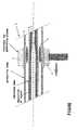
- the appended Figureschematically shows the position of the protective tube and the substrate tube according to the present invention.
- the construction 1that is shown in the Figure comprises the situation in which deposition of layers of glass (indicated at 6) on the internal surface of the substrate tube 3 has already taken place.
- the substrate tube 3 or preform 3is enveloped by a protective tube 4, which protective tube 4 is surrounded by a device 2 for generating plasma, in particular a resonator which can be moved along the length of the protective tube 4.
- the generation of the plasma in the annular space (indicated at 5) present between the outer circumference of the preform 3 and the inner circumference of the protective tube 4results in contraction of the preform 3 for the purpose of obtaining a massive or non-massive rod.
- the present inventionhas been implemented in the design of a preform doped with dopant A (Ge0 2 ).
- the resulting maximum index contrast thereofis more than 2.5% and the difference between the coefficient of thermal expansion of this layer and that of the cladding is greater than 3.4.10 -6 K -1 .
- the present inventionhas also been implemented in the design of a preform doped with dopant A as described above, and with substance B as a co-dopant.
- the difference between the coefficient of thermal expansion of this layer and that of the claddingis greater than 4.10 -6 K -1 in this case.
- the protective tube being usedis a tube having an external diameter of 34 mm and a wall thickness of 4 mm.
- the substrate tube being usedhas an external diameter of 22 mm and a wall thickness of 2 mm. Given a thickness of the deposited material of 1 mm in total, a massive rod of 14.6 mm is obtained after contraction in the case of a substrate tube firing loss during contraction of about 10%.
- the preform from which the desired optical fibre can be drawnis obtained.
- the desired core diameter of 7 ⁇ mresults if 0.029 mm of the final deposited layers has been deposited as the core material during the PCVD-process.
- the diameter of the total deposited layers in the fibreis 48.5 ⁇ m. Given a useful preform length of 40 cm, a length of fibre of 15 km can be produced from said preform.
Landscapes
- Chemical & Material Sciences (AREA)
- Engineering & Computer Science (AREA)
- Materials Engineering (AREA)
- Organic Chemistry (AREA)
- General Chemical & Material Sciences (AREA)
- Physics & Mathematics (AREA)
- Geochemistry & Mineralogy (AREA)
- Life Sciences & Earth Sciences (AREA)
- Chemical Kinetics & Catalysis (AREA)
- Manufacturing & Machinery (AREA)
- General Life Sciences & Earth Sciences (AREA)
- Plasma & Fusion (AREA)
- Fluid Mechanics (AREA)
- Spectroscopy & Molecular Physics (AREA)
- Optics & Photonics (AREA)
- Manufacture, Treatment Of Glass Fibers (AREA)
- Surface Treatment Of Glass Fibres Or Filaments (AREA)
Abstract
Description
- The present invention relates to a method and a device for manufacturing optical preforms, in which one or more layers of glass, doped or undoped, are deposited onto the internal surface of a hollow substrate tube, which deposition is effected by supplying one or more reactive gas mixtures of glass-forming compounds to the interior of the hollow substrate tube and subsequently generating a non-isothermal plasma in the hollow substrate tube, after which the hollow substrate tube or preform, on the internal surface of which a plurality of layers of glass obtained by means of a deposition process are present, is subjected to a contraction process for the purpose of forming a massive rod, from which optical fibres are drawn. The present invention furthermore relates to optical fibres that are obtained by using such a method and device.
- From
US Pat. No. 4,746,345 there is known a method of manufacturing solid quartz glass preforms from hollow substrate tubes, in which a plasma burner consisting of two quartz tubes and a coil is reciprocated along the length of a hollow substrate tube. The plasma is ignited and maintained in the gaseous atmosphere that envelopes the substrate tube to be contracted, in which the dimension of the plasma burner is significantly smaller than the length of a substrate tube. - From
US Pat. No. 5,203,691 there is known a burner which is used for contracting hollow substrate tubes into solid massive preforms, which process does not employ plasma, however. - From
U.S. Pat. No. 4,493,721 there is known a method of manufacturing an optical fiber, wherein the inner wall of a glass tube is etched with a fluorine compound before depositing core glass on the inner wall to form a coating. - A method of manufacturing optical fibres is known per se from
US Pat. Nos. 4,314,833 ;4,844,007 andRe. 30.635 . The optical fibres produced by such a method may consist of a core of doped silica glass and a cladding of undoped silica glass. Alternatively, the fibre may consist of a core of either undoped or doped silica glass, a first cladding layer of doped silica glass, and an outer cladding of undoped silica glass. The dopant, depending on its type, may increase or decrease the refractive index of silica. Dopants such as Ge02, Al203, and Ti02 will increase the refractive index, while dopants such as B203, or F will decrease the refractive index. In an optical fibre, the refractive index of the core layer material is higher than the layer of glass surrounding the core. There may be a stepped increase or a parabolic increase of the core refractive index. - In the aforesaid two US patents, the preform from which the optical fibre is drawn in a draw tower is produced in two separate steps, viz. a) the deposition of a number of thin, doped or undoped layers of quartz on the internal surface of the hollow preform or substrate tube, followed by b) the contracting or collapsing process, in which the previously obtained hollow substrate tube, which is internally coated with layers of quartz, is formed into the final massive preform by moving high-temperature heating means along the tube. According to this known PCVD-process, the deposition of the doped or undoped layers of quartz on the interior of the hollow substrate tube is effected by generating a plasma in a reactive gas mixture that is present within the substrate tube. Said reactive gas mixture is maintained at the desired chemical composition and the desired low pressure by means of a control system, and the plasma is generated by microwave rays whose energy is coupled into the ionised reactive gas mixture in a substrate tube from a resonator which is disposed outside the substrate tube. A so-called circular symmetrical deposition of layers of glass, which is substantially uniform in the longitudinal direction of the hollow substrate tube, is obtained by moving the resonator in the longitudinal direction with respect to the hollow substrate tube. In order to achieve an optimum deposition process, the hollow substrate tube is maintained at a temperature of about 1200 °C by placing the whole of substrate tube and moving resonator in a movable furnace, in which the resonator is provided with an insulating envelope so as to ensure the proper functioning thereof, and in which furthermore cooling of the resonator takes place. After completion of the deposition process as described above, the substrate tube comprising the layers of glass internally deposited thereon is manually removed from the PCVD apparatus and subsequently set up in a contraction apparatus. Usually, a hydrogen-oxygen burner or an electrical furnace is used for the contraction process, in which case the hollow substrate tube is formed into the desired massive preform in a number of passes. A massive rod thus obtained, also called preform, possibly being externally coated with additional glass, is set up in a draw tower and an optical fibre is drawn therefrom.
- The process of preform manufacture as described above can thus be considered to be a method in which two separate process steps can be distinguished, each step to be carried out in a separate apparatus. An important drawback is the fact that, owing to the cooling of the substrate tube that takes place upon transfer of the tube, the internal stress in the layers deposited on the interior of the substrate tube will increase to such an extent that a so-called "layer breakage" will occur, which renders the substrate tube unsuitable for further processing in the draw tower. Such a "layer breakage" results in preform losses, which phenomenon occurs in particular when manufacturing preforms exhibiting a high refractive index contrast or large differences between the coefficients of thermal expansion of the deposited layers resulting from the use of one or more types of dopants. Such a phenomenon occurs in particular when producing specific types of multimode fibres, fibres for sensor applications, photosensitive fibres, fibres for dispersion compensating modules, fibres containing special reinforcing dopants for amplification properties and the like. It is desirable to use higher refractive index contrasts, higher amounts of dopants and/or different types of dopants when designing such fibres. The production techniques that are commercially available at present only allow the production of fibres having a maximum refractive index contrast of about 2%, however, and the fibres are usually so-called graded index fibres. It is desirable, therefore, that optical fibres be produced in which specific layers exhibit a refractive index contrast higher than the that which is known.according to the prior art, in particular a value higher than 2.5%.
- If it is decided to use dopants in a specific layer of an optical fibre whose structure strongly differs from the undoped quartz structure, this will lead to major differences between the coefficients of thermal expansion. In the prior art, a maximum difference of 3.2 x 10⁻⁶ K-1 in the coefficients of thermal expansion of the various layers arranged adjacently to each other was considered to be attainable when manufacturing optical fibres. If, on the other hand, it should be decided to use special dopants, it is desirable that optical fibres be produced in which the differences between the coefficients of thermal expansion of the layers arranged adjacently to each other may be larger than the aforesaid value, in particular larger than 3.4 x 10⁻⁶ K-1.
- It should be understood that if layers exhibiting large differences in the coefficients of thermal expansion are present in the substrate tube, stress differences between the layers may occur upon cooling down, which may lead to the development of lines of fracture in the various layers, and, in the worst case, to fracture of the entire preform. In practice it has moreover become apparent that the aforesaid separate process steps may lead to drawbacks, in particular upon removal of the substrate tube from the PCVD apparatus and the subsequent setting-up of the substrate tube in the contraction apparatus, which operations may lead to fouling of the internal surface of the substrate tube.
- One aspect of the present invention is thus to provide a method and a device for manufacturing optical preforms which do not exhibit the problems of the prior art as referred to above.
- Another aspect of the present invention is to provide a method and a device for manufacturing optical preforms, which optical preforms are composed so that optical fibres exhibiting a high refractive index contrast can be drawn therefrom.
- Another aspect of the present invention is to provide a method and a device for manufacturing optical preforms, according to which optical fibres can be drawn from said optical preforms, which optical fibres are composed of one or more layers whose coefficients of thermal expansion differ strongly from each other.
- Yet another aspect of the present invention is to provide a method and a device for manufacturing optical preforms, according to which a non-isothermal plasma is used both in the contraction process and in the deposition process.
- An additional object of the present invention is to provide a method and a device for manufacturing optical preforms, according to which the deposition process and the contraction process are carried out in one and the same device, viz. an integrated PCVD/collapsing machine.
- The invention as referred to in the introduction ischaracterized in that the contraction process comprises the steps of:
- i) providing a hollow substrate tube enveloped by a protective tube, which protective tube is stationary with respect to the hollow substrate tube, with the hollow substrate tube being enveloped by the protective tube along substantially the entire length thereof,
- ii) providing a resonator which surrounds the protective tube,
- iii) supplying a plasma-forming gas to the annular space present between the outer circumference of the hollow substrate tube and the inner circumference of the protective tube,
- iv) generating a non-isothermal plasma in said annular space,
- v) reciprocating the resonator in longitudinal direction with respect to the protective tube for the purpose of contracting the hollow preform into a massive rod, followed by controlled cooling thereof.
- The use of a protective tube as described in step i) makes it possible to use the same microwave energy source that is used for the deposition process and for the contraction process as well. Thus, a plasma to be used in the contraction process is generated in the annular space present between the outer circumference of the hollow substrate tube and the inner circumference of the protective tube, which plasma generation takes place in such a manner that the microwave energy being used is relatively high whilst the resonator speed is low. In addition, the special construction of the protective tube and the substrate tube, according to which in particular the substrate tube is enveloped by the protective tube along substantially the entire length thereof, enables a reproducible and controllable contraction of the substrate tube. In the present description the term hollow substrate tube or preform is consistently used. These two terms are in fact considered to be synonyms by those skilled in the art, and it will become apparent from the context whether or not layers are already internally deposited thereon.
- In a special embodiment it is desirable to introduce a gas having a high temperature into the annular space present between the outer circumference of the hollow substrate tube and the inner circumference of the protective tube during the deposition process. This makes it possible for the outer wall of the substrate tube to reach the same temperature as in the situation in which an external furnace is used.
- In a special embodiment, on the other hand, it is possible to carry out the present contraction process in such a manner that the same plasma that was used for the deposition process is also used in carrying out the first contraction step. Such an embodiment enables much smaller differences to be chosen between the diameter of the outer circumference of the substrate tube and that of the outer circumference of the protective tube than originally. In addition to that, the conditions in which the circular plasma is to be generated in the annular space in such an embodiment are significantly more favourable than in the situation in which a large difference between the respective diameters is employed.
- It is in particular preferable to keep the hollow substrate tube and the protective tube in a horizontal position while carrying out the steps i)-iv), with the hollow substrate tube being rotated in particular during step v).
- In order to obtain a uniform contraction of the substrate tube, the plasma is preferably adapted to the increased volume of the annular space during step v).
- Preferably, a mixture of argon and oxygen is used as a suitable plasma-forming gas to be used in step iii), in which the pressure during the contraction process is preferably < 50 mbar, in particular 10-25 mbar.
- It should be understood that the contraction into a fully massive rod can be terminated prematurely in step v), for which contraction, as described at some length in the foregoing, the same plasma as used in the deposition process and/or the plasma generated in the annular space may be used. Such premature termination may be desirable for special products or in order to have the closing of the preform take place in the melting zone of the draw tower.
- Preferably, the protective tube is made of a ceramic material having a higher plasticizing temperature than the material of the hollow substrate tube to be contracted, in order to prevent the protective tube that envelopes the hollow substrate tube from plasticizing during step v) already.
- In a special embodiment, in which repeated use of the protective tube for carrying out the steps i)-v) must be possible, the protective tube is preferably provided with cooling means, for example by forming hollow channels in the outer wall of the protective tube, in order to prevent premature contraction of the protective tube.
- In a special embodiment, the protective tube used in step i) preferably functions as a jacket tube for the massive preform as well, which means that the contraction process comprises an additional step vi), which step vi) comprises the reciprocating of the resonator in longitudinal direction with respect to the protective tube for the purpose of contracting the protective tube, and the subsequent controlled cooling thereof. In such an embodiment the protective tube can be considered to be a jacket tube for the massive preform, after which the whole is set up in the draw tower as a complete preform for producing optical fibres.
- In particular, the deposition process and the contraction process are carried out in one and the same device, in which the construction for effecting the rotating passage is designed such that the removal of the eventually obtained massive preform and the protective tube can take place in a simple manner. In order to obtain such a construction, clamps supporting the protective tube and the end of the substrate tube have an open construction.
- It should be understood that the gas being used in step iii) may comprise one or more glass-forming compounds, so that an additional deposition takes place on the inner circumference and/or the outer circumference of the hollow protective tube.
- Using the present invention, it is thus possible to manufacture optical preforms which exhibit a high refractive index contrast or large differences between the coefficients of thermal expansion of the various layers deposited on the interior of the hollow substrate tube.
- The present invention furthermore relates to a device for carrying out the method as described above and defined in the independent apparatus claim.
- The present invention will be explained in more detail hereinafter by means of an example and with reference to a Figure; it should be noted, however, that the present invention is by no means limited to such a special example and such a Figure.
- The appended Figure schematically shows the position of the protective tube and the substrate tube according to the present invention.
- The
construction 1 that is shown in the Figure comprises the situation in which deposition of layers of glass (indicated at 6) on the internal surface of thesubstrate tube 3 has already taken place. Thesubstrate tube 3 orpreform 3 is enveloped by aprotective tube 4, whichprotective tube 4 is surrounded by adevice 2 for generating plasma, in particular a resonator which can be moved along the length of theprotective tube 4. The generation of the plasma in the annular space (indicated at 5) present between the outer circumference of thepreform 3 and the inner circumference of theprotective tube 4 results in contraction of thepreform 3 for the purpose of obtaining a massive or non-massive rod. - The present invention has been implemented in the design of a preform doped with dopant A (Ge02). The resulting maximum index contrast thereof is more than 2.5% and the difference between the coefficient of thermal expansion of this layer and that of the cladding is greater than 3.4.10-6 K-1. The present invention has also been implemented in the design of a preform doped with dopant A as described above, and with substance B as a co-dopant. The difference between the coefficient of thermal expansion of this layer and that of the cladding is greater than 4.10-6 K-1 in this case.
- The protective tube being used is a tube having an external diameter of 34 mm and a wall thickness of 4 mm. The substrate tube being used has an external diameter of 22 mm and a wall thickness of 2 mm. Given a thickness of the deposited material of 1 mm in total, a massive rod of 14.6 mm is obtained after contraction in the case of a substrate tube firing loss during contraction of about 10%. After fitting of a separate jacket tube having a cross-sectional area of 300 mm2, the preform from which the desired optical fibre can be drawn is obtained. In the case of a diameter of 125 µm, the desired core diameter of 7 µm results if 0.029 mm of the final deposited layers has been deposited as the core material during the PCVD-process. The diameter of the total deposited layers in the fibre is 48.5 µm. Given a useful preform length of 40 cm, a length of fibre of 15 km can be produced from said preform.
Claims (15)
- A method for manufacturing optical preforms, in which one or more layers of glass, doped or undoped, are deposited onto the internal surface of a hollow substrate tube, which deposition is effected by supplying one or more reactive gas mixtures of glass-forming compounds to the interior of the hollow substrate tube and subsequently generating a non-isothermal plasma in the hollow substrate tube, after which the substrate tube provided with layers of glass by means of a deposition process is subjected to a contraction process for the purpose of forming a massive rod, from which optical fibres are drawn,characterized in that the contraction process comprises the steps of:i) providing a hollow substrate tube enveloped by a protective tube, which protective tube is stationary with respect to the hollow substrate tube, with the follow substrate tube being enveloped by the protective tube along substantially the entire length thereof,ii) providing a resonator which surrounds the protective tube,iii) supplying a plasma-forming gas to the annular space present between the outer circumference of the hollow substrate tube and the inner circumference of the protective tube,iv) generating a non-isothermal plasma in said annular space,v) reciprocating the resonator in longitudinal direction with respect to the protective tube for the purpose of contracting the hollow preform into a massive rod.
- A method according to claim 1,characterized in that the hollow substrate tube and the protective tube are kept in a horizontal position while steps i)-iv) are being carried out.
- A method according to any one or more of the preceding claims,characterized in that the hollow substrate tube is rotated during step v), followed by controlled cooling thereof.
- A method according to any one or more of the preceding claims,characterized in that the plasma is adapted to the increased volume of the annular space during step v).
- A method according to any one or more of the preceding claims,characterized in that a mixture of argon and oxygen is used as a plasma-forming gas.
- A method according to any one or more of the preceding claims,characterized in that the pressure during the contraction process is < 50 mbar, in particular 10-25 mbar.
- A method according to any one or more of the preceding claims,characterized in that a gas having a high temperature during the deposition process is introduced into said annular space.
- A method according to any one or more of the preceding claims,characterized in that the protective tube is made of a ceramic material having a higher plasticizing temperature than the material of the hollow substrate tube to be contracted.
- A method according to any one or more of the preceding claims,characterized in that the contraction process comprises an additional step vi), which step vi) comprises the reciprocating of the resonator in longitudinal direction with respect to the protective tube for the purpose of contracting the protective tube.
- A method according to any one or more of the preceding claims,characterized in that the protective tube is provided with cooling means.
- A method according to any one or more of the preceding claims,characterized in that the deposition process and the contraction process are carried out in one and the same device.
- A method according to any one or more of the preceding claims,characterized in that the contraction process is carried out following on the deposition process.
- A method according to any one or more of the preceding claims,characterized in that one or more glass-forming compounds is (are) added to the gas used in step iii).
- A method according to any one or more of the preceding claims,characterized in that the contraction into a fully massive rod is terminated prematurely in step v), for which contraction the same plasma as used in the deposition process and/or the plasma generated in the annular space may be used.
- A device for depositing one or more glass layers onto the internal surface of a hollow substrate tube and contracting said substrate tube into a massive or non-massive preform, comprising means for supplying one or more reactive gas mixtures of glass forming compounds to the interior of the hollow substrate tube, means for rotating the substrate tube, means for heating the substrate tube and means for supporting the substrate tube,characterized in that the device furthermore comprises means for fitting a protective tube round the substrate tube, substantially along the entire length thereof, means for supplying gases to the annular space present between the outer circumference of the hollow substrate tube and the inner circumference of the protective tube, and means for generating a non-isothermal plasma in said annular space,
Applications Claiming Priority (3)
| Application Number | Priority Date | Filing Date | Title |
|---|---|---|---|
| NL1020358 | 2002-04-10 | ||
| NL1020358ANL1020358C2 (en) | 2002-04-10 | 2002-04-10 | Method and device for manufacturing optical preforms, as well as the optical fibers obtained therewith. |
| PCT/NL2003/000261WO2003086998A1 (en) | 2002-04-10 | 2003-04-07 | Method and device for manufacturing optical preforms, as well as the optical fibres obtained therewith |
Publications (2)
| Publication Number | Publication Date |
|---|---|
| EP1492735A1 EP1492735A1 (en) | 2005-01-05 |
| EP1492735B1true EP1492735B1 (en) | 2010-01-27 |
Family
ID=29244977
Family Applications (1)
| Application Number | Title | Priority Date | Filing Date |
|---|---|---|---|
| EP03725865AExpired - LifetimeEP1492735B1 (en) | 2002-04-10 | 2003-04-07 | Method and device for manufacturing optical preforms, as well as the optical fibers obtained herewith |
Country Status (8)
| Country | Link |
|---|---|
| US (1) | US7734135B2 (en) |
| EP (1) | EP1492735B1 (en) |
| CN (1) | CN1303023C (en) |
| AT (1) | ATE456543T1 (en) |
| AU (1) | AU2003228129A1 (en) |
| DE (1) | DE60331136D1 (en) |
| NL (1) | NL1020358C2 (en) |
| WO (1) | WO2003086998A1 (en) |
Cited By (1)
| Publication number | Priority date | Publication date | Assignee | Title |
|---|---|---|---|---|
| CN105271710A (en)* | 2015-11-13 | 2016-01-27 | 成都中住光纤有限公司 | Optical fiber drawing furnace |
Families Citing this family (9)
| Publication number | Priority date | Publication date | Assignee | Title |
|---|---|---|---|---|
| NL1020358C2 (en) | 2002-04-10 | 2003-10-13 | Draka Fibre Technology Bv | Method and device for manufacturing optical preforms, as well as the optical fibers obtained therewith. |
| FR2863605B1 (en)* | 2003-12-15 | 2006-04-28 | Cit Alcatel | PLASMA RECHARGING METHOD AROUND A FLUORINE DOPED TUBE |
| NL1032867C2 (en) | 2006-11-14 | 2008-05-15 | Draka Comteq Bv | Device and method for performing a deposition process of the PCVD type. |
| NL1033763C2 (en)* | 2007-04-26 | 2008-10-28 | Draka Comteq Bv | Device and method for manufacturing an optical preform. |
| NL1033773C2 (en)* | 2007-04-27 | 2008-10-28 | Draka Comteq Bv | Method for the manufacture of a preform and optical fiber obtainable therefrom. |
| NL1033783C2 (en)* | 2007-05-01 | 2008-11-06 | Draka Comteq Bv | Device for carrying out a plasma chemical vapor deposition as well as a method for manufacturing an optical preform. |
| US8252387B2 (en)* | 2007-12-10 | 2012-08-28 | Ofs Fitel, Llc | Method of fabricating optical fiber using an isothermal, low pressure plasma deposition technique |
| US8857372B2 (en)* | 2007-12-10 | 2014-10-14 | Ofs Fitel, Llc | Method of fabricating optical fiber using an isothermal, low pressure plasma deposition technique |
| NL2011077C2 (en)* | 2013-07-01 | 2015-01-05 | Draka Comteq Bv | A method for manufacturing a precursor for a primary preform for optical fibres by means of an internal plasma chemical vapour deposition (pcvd) process. |
Family Cites Families (17)
| Publication number | Priority date | Publication date | Assignee | Title |
|---|---|---|---|---|
| DE2444100C3 (en)* | 1974-09-14 | 1979-04-12 | Philips Patentverwaltung Gmbh, 2000 Hamburg | Process for the production of internally coated glass tubes for drawing optical fibers |
| JPS5812213B2 (en)* | 1978-05-16 | 1983-03-07 | 株式会社東芝 | Highly weather resistant multi-component glass fiber for optical communications |
| DE2929166A1 (en)* | 1979-07-19 | 1981-01-29 | Philips Patentverwaltung | METHOD FOR THE PRODUCTION OF OPTICAL FIBERS |
| JPS57181516A (en)* | 1981-05-01 | 1982-11-09 | Agency Of Ind Science & Technol | Heterogeneous refractive index lens |
| JPS5899131A (en)* | 1981-12-10 | 1983-06-13 | Nippon Telegr & Teleph Corp <Ntt> | Manufacturing method of optical glass material |
| NL8201453A (en)* | 1982-04-06 | 1983-11-01 | Philips Nv | METHOD FOR MANUFACTURING OPTICAL FIBERS |
| NL8402225A (en)* | 1984-07-13 | 1986-02-03 | Philips Nv | METHOD FOR MANUFACTURING SOLID GLASS PREFORMS FROM HOLLOW FORMS |
| DE3635034A1 (en)* | 1986-10-15 | 1988-04-21 | Philips Patentverwaltung | METHOD FOR THE PRODUCTION OF OPTICAL FIBERS |
| NL8602910A (en)* | 1986-11-17 | 1988-06-16 | Philips Nv | DEVICE FOR APPLYING GLASS LAYERS TO THE INSIDE OF A TUBE. |
| DE3824273A1 (en)* | 1988-07-16 | 1990-01-18 | Philips Patentverwaltung | METHOD FOR PRODUCING SOLID BODIES |
| US5203691A (en)* | 1988-08-30 | 1993-04-20 | At&T Bell Laboratories | Torch assembly for heating glassy tubes |
| US5397372A (en)* | 1993-11-30 | 1995-03-14 | At&T Corp. | MCVD method of making a low OH fiber preform with a hydrogen-free heat source |
| CN1117176C (en)* | 1997-12-31 | 2003-08-06 | 等离子光纤维股份有限公司 | Plasma chemical vapor deposition apparatus and method for manufacturing optical fiber, preform and ferrule, and optical fiber manufactured thereby |
| WO2000026150A1 (en)* | 1998-10-29 | 2000-05-11 | Sumitomo Electric Industries, Ltd. | Methods for producing preform and optical fiber |
| GB2397135B (en)* | 2001-06-08 | 2005-08-03 | Crystal Fibre As | Photonic bandgap optical fibre with higher index elongate cladding features |
| US6876791B2 (en)* | 2001-09-03 | 2005-04-05 | Sumitomo Electric Industries, Ltd. | Diffraction grating device |
| NL1020358C2 (en) | 2002-04-10 | 2003-10-13 | Draka Fibre Technology Bv | Method and device for manufacturing optical preforms, as well as the optical fibers obtained therewith. |
- 2002
- 2002-04-10NLNL1020358Apatent/NL1020358C2/ennot_activeIP Right Cessation
- 2003
- 2003-04-07USUS10/509,684patent/US7734135B2/ennot_activeExpired - Fee Related
- 2003-04-07CNCNB038133652Apatent/CN1303023C/ennot_activeExpired - Fee Related
- 2003-04-07ATAT03725865Tpatent/ATE456543T1/ennot_activeIP Right Cessation
- 2003-04-07EPEP03725865Apatent/EP1492735B1/ennot_activeExpired - Lifetime
- 2003-04-07AUAU2003228129Apatent/AU2003228129A1/ennot_activeAbandoned
- 2003-04-07DEDE60331136Tpatent/DE60331136D1/ennot_activeExpired - Lifetime
- 2003-04-07WOPCT/NL2003/000261patent/WO2003086998A1/enactiveApplication Filing
Cited By (1)
| Publication number | Priority date | Publication date | Assignee | Title |
|---|---|---|---|---|
| CN105271710A (en)* | 2015-11-13 | 2016-01-27 | 成都中住光纤有限公司 | Optical fiber drawing furnace |
Also Published As
| Publication number | Publication date |
|---|---|
| EP1492735A1 (en) | 2005-01-05 |
| CN1659108A (en) | 2005-08-24 |
| WO2003086998A1 (en) | 2003-10-23 |
| CN1303023C (en) | 2007-03-07 |
| DE60331136D1 (en) | 2010-03-18 |
| ATE456543T1 (en) | 2010-02-15 |
| AU2003228129A1 (en) | 2003-10-27 |
| NL1020358C2 (en) | 2003-10-13 |
| US7734135B2 (en) | 2010-06-08 |
| US20070003197A1 (en) | 2007-01-04 |
Similar Documents
| Publication | Publication Date | Title |
|---|---|---|
| US6053013A (en) | Apparatus and method for overcladding optical fiber preform rod and optical fiber drawing method | |
| EP1867610B1 (en) | Apparatus for carrying out a plasma chemical vapour deposition (PCVD) process and method for manufacturing an optical fibre | |
| EP1740510B1 (en) | Method for fabricating an optical fiber and preform for fabricating an optical fiber | |
| CA1157654A (en) | Method of producing optical fibers | |
| US4090055A (en) | Apparatus for manufacturing an optical fibre with plasma activated deposition in a tube | |
| US7946134B2 (en) | MCVD optical fiber method with partial removal of substrate tube | |
| WO2015107931A1 (en) | Method for producing optical fiber preform and method for producing optical fiber | |
| JP5459977B2 (en) | Apparatus for performing plasma enhanced chemical vapor deposition and method for producing optical preforms | |
| EP1492735B1 (en) | Method and device for manufacturing optical preforms, as well as the optical fibers obtained herewith | |
| US4597787A (en) | Manufacture of optical fibre preforms | |
| CN101987779B (en) | Method and device for manfacturing a primary preform for optical fibres | |
| CN101987778B (en) | A method for manufacturing a primary preform for optical fibres | |
| US5076824A (en) | Method of making fiber optical preform with pyrolytic coated mandrel | |
| RU2236386C2 (en) | Method of manufacturing optic fiber intermediate product | |
| US7437893B2 (en) | Method for producing optical glass | |
| EP0024412B1 (en) | Optical fiber fabrication process | |
| EP0072069A1 (en) | Method of producing preforms for drawing optical fibres and apparatus for the continuous production of optical fibres | |
| US20090260400A1 (en) | Method for Producing a Tubular Semifinished Product From Fluorine-Doped Quartz Glass | |
| US6796270B2 (en) | Device for producing PCVD coated glass tubes for the drawing of optical fibers | |
| KR20060093671A (en) | Multi-mode fiber and its manufacturing method | |
| Hewak | Fabrication of optical fiber | |
| JPS61236626A (en) | Production of base material for optical fiber |
Legal Events
| Date | Code | Title | Description |
|---|---|---|---|
| PUAI | Public reference made under article 153(3) epc to a published international application that has entered the european phase | Free format text:ORIGINAL CODE: 0009012 | |
| 17P | Request for examination filed | Effective date:20041006 | |
| AK | Designated contracting states | Kind code of ref document:A1 Designated state(s):AT BE BG CH CY CZ DE DK EE ES FI FR GB GR HU IE IT LI LU MC NL PT RO SE SI SK TR | |
| AX | Request for extension of the european patent | Extension state:AL LT LV MK | |
| 17Q | First examination report despatched | Effective date:20080725 | |
| GRAP | Despatch of communication of intention to grant a patent | Free format text:ORIGINAL CODE: EPIDOSNIGR1 | |
| GRAS | Grant fee paid | Free format text:ORIGINAL CODE: EPIDOSNIGR3 | |
| GRAA | (expected) grant | Free format text:ORIGINAL CODE: 0009210 | |
| AK | Designated contracting states | Kind code of ref document:B1 Designated state(s):AT BE BG CH CY CZ DE DK EE ES FI FR GB GR HU IE IT LI LU MC NL PT RO SE SI SK TR | |
| REG | Reference to a national code | Ref country code:GB Ref legal event code:FG4D | |
| REG | Reference to a national code | Ref country code:CH Ref legal event code:EP | |
| REG | Reference to a national code | Ref country code:IE Ref legal event code:FG4D | |
| REF | Corresponds to: | Ref document number:60331136 Country of ref document:DE Date of ref document:20100318 Kind code of ref document:P | |
| REG | Reference to a national code | Ref country code:NL Ref legal event code:VDEP Effective date:20100127 | |
| PG25 | Lapsed in a contracting state [announced via postgrant information from national office to epo] | Ref country code:AT Free format text:LAPSE BECAUSE OF FAILURE TO SUBMIT A TRANSLATION OF THE DESCRIPTION OR TO PAY THE FEE WITHIN THE PRESCRIBED TIME-LIMIT Effective date:20100127 | |
| PG25 | Lapsed in a contracting state [announced via postgrant information from national office to epo] | Ref country code:NL Free format text:LAPSE BECAUSE OF FAILURE TO SUBMIT A TRANSLATION OF THE DESCRIPTION OR TO PAY THE FEE WITHIN THE PRESCRIBED TIME-LIMIT Effective date:20100127 Ref country code:ES Free format text:LAPSE BECAUSE OF FAILURE TO SUBMIT A TRANSLATION OF THE DESCRIPTION OR TO PAY THE FEE WITHIN THE PRESCRIBED TIME-LIMIT Effective date:20100508 Ref country code:PT Free format text:LAPSE BECAUSE OF FAILURE TO SUBMIT A TRANSLATION OF THE DESCRIPTION OR TO PAY THE FEE WITHIN THE PRESCRIBED TIME-LIMIT Effective date:20100527 | |
| PG25 | Lapsed in a contracting state [announced via postgrant information from national office to epo] | Ref country code:SI Free format text:LAPSE BECAUSE OF FAILURE TO SUBMIT A TRANSLATION OF THE DESCRIPTION OR TO PAY THE FEE WITHIN THE PRESCRIBED TIME-LIMIT Effective date:20100127 Ref country code:FI Free format text:LAPSE BECAUSE OF FAILURE TO SUBMIT A TRANSLATION OF THE DESCRIPTION OR TO PAY THE FEE WITHIN THE PRESCRIBED TIME-LIMIT Effective date:20100127 | |
| PG25 | Lapsed in a contracting state [announced via postgrant information from national office to epo] | Ref country code:EE Free format text:LAPSE BECAUSE OF FAILURE TO SUBMIT A TRANSLATION OF THE DESCRIPTION OR TO PAY THE FEE WITHIN THE PRESCRIBED TIME-LIMIT Effective date:20100127 Ref country code:GR Free format text:LAPSE BECAUSE OF FAILURE TO SUBMIT A TRANSLATION OF THE DESCRIPTION OR TO PAY THE FEE WITHIN THE PRESCRIBED TIME-LIMIT Effective date:20100428 Ref country code:BE Free format text:LAPSE BECAUSE OF FAILURE TO SUBMIT A TRANSLATION OF THE DESCRIPTION OR TO PAY THE FEE WITHIN THE PRESCRIBED TIME-LIMIT Effective date:20100127 Ref country code:SE Free format text:LAPSE BECAUSE OF FAILURE TO SUBMIT A TRANSLATION OF THE DESCRIPTION OR TO PAY THE FEE WITHIN THE PRESCRIBED TIME-LIMIT Effective date:20100127 Ref country code:CY Free format text:LAPSE BECAUSE OF FAILURE TO SUBMIT A TRANSLATION OF THE DESCRIPTION OR TO PAY THE FEE WITHIN THE PRESCRIBED TIME-LIMIT Effective date:20100127 Ref country code:RO Free format text:LAPSE BECAUSE OF FAILURE TO SUBMIT A TRANSLATION OF THE DESCRIPTION OR TO PAY THE FEE WITHIN THE PRESCRIBED TIME-LIMIT Effective date:20100127 | |
| PG25 | Lapsed in a contracting state [announced via postgrant information from national office to epo] | Ref country code:MC Free format text:LAPSE BECAUSE OF NON-PAYMENT OF DUE FEES Effective date:20100430 Ref country code:BG Free format text:LAPSE BECAUSE OF FAILURE TO SUBMIT A TRANSLATION OF THE DESCRIPTION OR TO PAY THE FEE WITHIN THE PRESCRIBED TIME-LIMIT Effective date:20100427 Ref country code:CZ Free format text:LAPSE BECAUSE OF FAILURE TO SUBMIT A TRANSLATION OF THE DESCRIPTION OR TO PAY THE FEE WITHIN THE PRESCRIBED TIME-LIMIT Effective date:20100127 Ref country code:SK Free format text:LAPSE BECAUSE OF FAILURE TO SUBMIT A TRANSLATION OF THE DESCRIPTION OR TO PAY THE FEE WITHIN THE PRESCRIBED TIME-LIMIT Effective date:20100127 | |
| REG | Reference to a national code | Ref country code:CH Ref legal event code:PL | |
| PLBE | No opposition filed within time limit | Free format text:ORIGINAL CODE: 0009261 | |
| STAA | Information on the status of an ep patent application or granted ep patent | Free format text:STATUS: NO OPPOSITION FILED WITHIN TIME LIMIT | |
| 26N | No opposition filed | Effective date:20101028 | |
| PG25 | Lapsed in a contracting state [announced via postgrant information from national office to epo] | Ref country code:IE Free format text:LAPSE BECAUSE OF NON-PAYMENT OF DUE FEES Effective date:20100407 Ref country code:DK Free format text:LAPSE BECAUSE OF FAILURE TO SUBMIT A TRANSLATION OF THE DESCRIPTION OR TO PAY THE FEE WITHIN THE PRESCRIBED TIME-LIMIT Effective date:20100127 | |
| PG25 | Lapsed in a contracting state [announced via postgrant information from national office to epo] | Ref country code:CH Free format text:LAPSE BECAUSE OF NON-PAYMENT OF DUE FEES Effective date:20100430 Ref country code:LI Free format text:LAPSE BECAUSE OF NON-PAYMENT OF DUE FEES Effective date:20100430 | |
| PG25 | Lapsed in a contracting state [announced via postgrant information from national office to epo] | Ref country code:IT Free format text:LAPSE BECAUSE OF FAILURE TO SUBMIT A TRANSLATION OF THE DESCRIPTION OR TO PAY THE FEE WITHIN THE PRESCRIBED TIME-LIMIT Effective date:20100127 | |
| PG25 | Lapsed in a contracting state [announced via postgrant information from national office to epo] | Ref country code:HU Free format text:LAPSE BECAUSE OF FAILURE TO SUBMIT A TRANSLATION OF THE DESCRIPTION OR TO PAY THE FEE WITHIN THE PRESCRIBED TIME-LIMIT Effective date:20100728 Ref country code:LU Free format text:LAPSE BECAUSE OF NON-PAYMENT OF DUE FEES Effective date:20100407 | |
| PG25 | Lapsed in a contracting state [announced via postgrant information from national office to epo] | Ref country code:TR Free format text:LAPSE BECAUSE OF FAILURE TO SUBMIT A TRANSLATION OF THE DESCRIPTION OR TO PAY THE FEE WITHIN THE PRESCRIBED TIME-LIMIT Effective date:20100127 | |
| PGFP | Annual fee paid to national office [announced via postgrant information from national office to epo] | Ref country code:GB Payment date:20140428 Year of fee payment:12 | |
| PGFP | Annual fee paid to national office [announced via postgrant information from national office to epo] | Ref country code:DE Payment date:20140429 Year of fee payment:12 Ref country code:FR Payment date:20140417 Year of fee payment:12 | |
| REG | Reference to a national code | Ref country code:DE Ref legal event code:R119 Ref document number:60331136 Country of ref document:DE | |
| GBPC | Gb: european patent ceased through non-payment of renewal fee | Effective date:20150407 | |
| PG25 | Lapsed in a contracting state [announced via postgrant information from national office to epo] | Ref country code:GB Free format text:LAPSE BECAUSE OF NON-PAYMENT OF DUE FEES Effective date:20150407 Ref country code:DE Free format text:LAPSE BECAUSE OF NON-PAYMENT OF DUE FEES Effective date:20151103 | |
| REG | Reference to a national code | Ref country code:FR Ref legal event code:ST Effective date:20151231 | |
| PG25 | Lapsed in a contracting state [announced via postgrant information from national office to epo] | Ref country code:FR Free format text:LAPSE BECAUSE OF NON-PAYMENT OF DUE FEES Effective date:20150430 |