EP1487581B1 - Microfluidic channel network device - Google Patents
Microfluidic channel network deviceDownload PDFInfo
- Publication number
- EP1487581B1 EP1487581B1EP03716414AEP03716414AEP1487581B1EP 1487581 B1EP1487581 B1EP 1487581B1EP 03716414 AEP03716414 AEP 03716414AEP 03716414 AEP03716414 AEP 03716414AEP 1487581 B1EP1487581 B1EP 1487581B1
- Authority
- EP
- European Patent Office
- Prior art keywords
- channel
- fluid
- microfluidic
- circuit unit
- junction
- Prior art date
- Legal status (The legal status is an assumption and is not a legal conclusion. Google has not performed a legal analysis and makes no representation as to the accuracy of the status listed.)
- Expired - Lifetime
Links
Images


Classifications
- G—PHYSICS
- G01—MEASURING; TESTING
- G01N—INVESTIGATING OR ANALYSING MATERIALS BY DETERMINING THEIR CHEMICAL OR PHYSICAL PROPERTIES
- G01N15/00—Investigating characteristics of particles; Investigating permeability, pore-volume or surface-area of porous materials
- G01N15/10—Investigating individual particles
- G01N15/14—Optical investigation techniques, e.g. flow cytometry
- G01N15/1404—Handling flow, e.g. hydrodynamic focusing
- B—PERFORMING OPERATIONS; TRANSPORTING
- B01—PHYSICAL OR CHEMICAL PROCESSES OR APPARATUS IN GENERAL
- B01L—CHEMICAL OR PHYSICAL LABORATORY APPARATUS FOR GENERAL USE
- B01L2200/00—Solutions for specific problems relating to chemical or physical laboratory apparatus
- B01L2200/06—Fluid handling related problems
- B01L2200/0636—Focussing flows, e.g. to laminate flows
- B—PERFORMING OPERATIONS; TRANSPORTING
- B01—PHYSICAL OR CHEMICAL PROCESSES OR APPARATUS IN GENERAL
- B01L—CHEMICAL OR PHYSICAL LABORATORY APPARATUS FOR GENERAL USE
- B01L2300/00—Additional constructional details
- B01L2300/06—Auxiliary integrated devices, integrated components
- B01L2300/0627—Sensor or part of a sensor is integrated
- B—PERFORMING OPERATIONS; TRANSPORTING
- B01—PHYSICAL OR CHEMICAL PROCESSES OR APPARATUS IN GENERAL
- B01L—CHEMICAL OR PHYSICAL LABORATORY APPARATUS FOR GENERAL USE
- B01L2300/00—Additional constructional details
- B01L2300/08—Geometry, shape and general structure
- B01L2300/0861—Configuration of multiple channels and/or chambers in a single devices
- B01L2300/0864—Configuration of multiple channels and/or chambers in a single devices comprising only one inlet and multiple receiving wells, e.g. for separation, splitting
- G—PHYSICS
- G01—MEASURING; TESTING
- G01N—INVESTIGATING OR ANALYSING MATERIALS BY DETERMINING THEIR CHEMICAL OR PHYSICAL PROPERTIES
- G01N15/00—Investigating characteristics of particles; Investigating permeability, pore-volume or surface-area of porous materials
- G01N15/10—Investigating individual particles
- G01N15/14—Optical investigation techniques, e.g. flow cytometry
- G01N15/149—Optical investigation techniques, e.g. flow cytometry specially adapted for sorting particles, e.g. by their size or optical properties
- Y—GENERAL TAGGING OF NEW TECHNOLOGICAL DEVELOPMENTS; GENERAL TAGGING OF CROSS-SECTIONAL TECHNOLOGIES SPANNING OVER SEVERAL SECTIONS OF THE IPC; TECHNICAL SUBJECTS COVERED BY FORMER USPC CROSS-REFERENCE ART COLLECTIONS [XRACs] AND DIGESTS
- Y10—TECHNICAL SUBJECTS COVERED BY FORMER USPC
- Y10T—TECHNICAL SUBJECTS COVERED BY FORMER US CLASSIFICATION
- Y10T436/00—Chemistry: analytical and immunological testing
- Y10T436/11—Automated chemical analysis
- Y10T436/117497—Automated chemical analysis with a continuously flowing sample or carrier stream
- Y10T436/118339—Automated chemical analysis with a continuously flowing sample or carrier stream with formation of a segmented stream
- Y—GENERAL TAGGING OF NEW TECHNOLOGICAL DEVELOPMENTS; GENERAL TAGGING OF CROSS-SECTIONAL TECHNOLOGIES SPANNING OVER SEVERAL SECTIONS OF THE IPC; TECHNICAL SUBJECTS COVERED BY FORMER USPC CROSS-REFERENCE ART COLLECTIONS [XRACs] AND DIGESTS
- Y10—TECHNICAL SUBJECTS COVERED BY FORMER USPC
- Y10T—TECHNICAL SUBJECTS COVERED BY FORMER US CLASSIFICATION
- Y10T436/00—Chemistry: analytical and immunological testing
- Y10T436/25—Chemistry: analytical and immunological testing including sample preparation
- Y10T436/25375—Liberation or purification of sample or separation of material from a sample [e.g., filtering, centrifuging, etc.]
- Y—GENERAL TAGGING OF NEW TECHNOLOGICAL DEVELOPMENTS; GENERAL TAGGING OF CROSS-SECTIONAL TECHNOLOGIES SPANNING OVER SEVERAL SECTIONS OF THE IPC; TECHNICAL SUBJECTS COVERED BY FORMER USPC CROSS-REFERENCE ART COLLECTIONS [XRACs] AND DIGESTS
- Y10—TECHNICAL SUBJECTS COVERED BY FORMER USPC
- Y10T—TECHNICAL SUBJECTS COVERED BY FORMER US CLASSIFICATION
- Y10T436/00—Chemistry: analytical and immunological testing
- Y10T436/25—Chemistry: analytical and immunological testing including sample preparation
- Y10T436/2575—Volumetric liquid transfer
Definitions
- This inventionrelates to microfluidic devices and methods for performing analytical testing, and in particular, to a group of devices and methods that use microfluidic technology to join and analyze multiple fluids.
- Microfluidic devicesare becoming increasingly popular for performing analytical testing. Tools developed by the semiconductor industry for miniaturizing electronics enable fabrication and inexpensive mass production of intricate fluid systems. Microfluidic systems are increasingly utilized in performing a variety of analytical techniques for the acquisition of information in multiple disciplines, including the medical field, life sciences, and drug discovery and development.
- microfluidic devicesthere are different ways to manufacture microfluidic devices, including traditional lithographic techniques, soft lithography, and laminate technologies.
- laminate fabricationthe device consists of layers of material or lamina that have been cut, such as by a laser or stamp, into the desired shape and then held together with some form of adhesive, most commonly pressure-sensitive or thermally-activated adhesive. Maylar is commonly used, although other materials such as glass and polydimethylsiloxane (PDMS) have also been successfully incorporated into laminate devices.
- Microfluidic device constructionmay include a multi-layer laminated structure where each layer has channels and structures fabricated from a laminate material, forming microscale voids or channels where fluids flow.
- a microscale channelis generally defined as a fluid passage with at least one internal cross-sectional dimension that is less than 500 micrometers and typically between about 0.1 micrometers and about 500 micrometers. Either external pressurized fluid forced into the laminate or structures located within the laminate affect the control and pumping of fluids through these channels.
- fluidsUnder microfluidic conditions, fluids usually flow in a very predictable, laminar fashion, thereby allowing multiple fluids to flow next to each other in the same channel without turbulent mixing or the need for physical separation by a membrane. This is known as the laminar fluid diffusion interface. Smaller particles typically diffuse quickly across the boundary layer, whereas large molecules and particles, such as cells, typically diffuse only minimally.
- U.S. Patent No. 5,716,852teaches a method for analyzing the presence and concentration of small particles in a flow cell using laminar flow and diffusion principles. Described is a channel cell system for detecting the presence of analyte particles in a sample stream using a laminar flow channel having at least two inlet means which provide an indicator stream and a sample stream, where the laminar flow channel has a depth sufficiently small to force laminar flow of the streams and length sufficient for diffusion of particles of the analyte into the indicator stream to form a detection area, and having an outlet out of the channel to form a single mixed stream.
- This devicewhich is known as a T-Sensor, may contain an external detecting means for detecting diffusion boundries in the indicator stream.
- This detecting meansmay be provided by any means known in the art, including optical means such as optical spectroscopy, or absorption spectroscopy of fluorescence.
- US 6 270 641discloses a low dispersion device for joining two or more samples.
- the inventionconcerns a microfluidic device and a method of converging and analysing fluids in accordance with claims 1 and 19 respectively. Preferred embodiments of the invention are described in the appended dependent claims.
- the devicecomprises a microfluidic junction, an outlet channel, and a plurality of circuit units.
- a microfluidic junctionis an area for converging multiple fluids.
- An outlet channelis capable of receiving fluid from the microfluidic junction.
- An outlet channelincludes a first end connected with the microfluidic junction, a second end connected with a waste reservoir, and an analysis region positioned between the first end and the second end of the outlet channel.
- the devicealso includes a plurality of circuit units.
- Each circuit unitincludes a source channel with a first end capable of receiving sample fluid and a second end connected with the microfluidic junction; a branch channel connected with the source channel at an intersection; and a flow diversion system capable of differentially directing fluid flowing through a source channel either into the microfluidic junction or into a branch channel.
- a microfluidic junctioncan include a chamber connected with an outlet channel and a plurality of inlets.
- the plurality of inletsare typically positioned along the chamber as to alow fluid to enter the chamber without obstructing neighboring inlets.
- the cross-sectional area of each inletincreases as progressing toward the center of the chamber.
- each inletis separated by an intermediary region.
- An intermediary regionmay be uniformly convex or may comprise the meeting of two linear surfaces such as to create an edge.
- an intermediary regionmay contain either a hydrophobic or hydrophilic material deposited along its length.
- a circuit unitmay comprise a valved circuit unit.
- a valved circuit unitis a circuit unit containing valves.
- a valved circuit unitmay have a first valve positioned along a branch channel of the circuit unit and a second valve positioned along a source channel of the circuit unit.
- the first and second valvesare typically located at, near or proximate to the intersection of the branch channel and the source channel of a given circuit unit.
- valvescan be pneumatic valves.
- a circuit unitmay also comprise a valveless circuit unit, or a circuit unit comprising valveless liquid microswitches.
- microfluidicis generally defined as a substrate having a fluid passage with at least one internal cross-sectional dimension that is less than 500 micrometers and typically between about 0.1 micrometers and about 500 micrometers.
- channelrefers to a microfluidic channel and describes fluid elements dimensioned so that flow therein is substantially laminar.
- sampleis used in its broadest sense. Sample is meant to include any particles, chemicals, elements, cells, specimen or culture obtained from any source, including without limitation chemical, biological and environmental samples. Sample may be obtained from animals (including humans) and encompass fluids, solids, tissues, and gases. Biological samples include, without limitation, cells and any components thereof, blood products, such as plasma, serum and the like, proteins, peptides, amino acids, polynucleotide, lipids, carbohydrates, and any combinations thereof. The sample may include chemicals, either organic or inorganic, used to interact with the interactive material. When the interactive material contains biological material, for example, drugs, chemicals or other biological molecules may be added to the samples to cause a reaction or response by, among or within the biological material.
- Environmental samplesinclude environmental material such as surface matter, soil, water, crystals and industrial samples.
- Channels and other microfluidic structurescan be microfabricated in a substrate to produce a cartridge.
- the term "cartridge”refers to a microfluidic device, which is typically, but not necessarily, disposable and which can be coupled with measurement, pumping, electronic, fluidic or other apparatus.
- the cartridgecan be microfabricated using a variety of methods, including without limitation, traditional lithographic techniques, soft lithography, laminate technologies, etc.
- the cartridgecan be microfabricated from any moldable, machinable or etchable substrate.
- machiningas used herein includes, without limitation printing, stamping, cutting and laser ablating.
- the cartridgecan be formed in a single sheet, in a pair of sheets sandwiched together, or in a plurality of sheets laminated together.
- the term "sheet”refers to any solid substrate, flexible or otherwise.
- the channelscan be etched in a silicon substrate and covered with a cover sheet, which can be a transparent cover sheet.
- the channel wallsare defined by removing material from at least one sheet, thus creating channels and voids, and positioning additional sheets on either side of the altered sheets.
- Any of the layerscan contain fluid channels. In some cases the channel is simply a hole (or fluid via) to route the fluid to the next fluid laminate layer. Any two adjacent laminate layers may be bonded together to form a more complex single part.
- Electroosmotic and pressure driven floware non-limiting examples of methods or systems for flow control.
- flowrefers to any type of movement of a liquid or solid through a microfluidic device or in a method according to the invention.
- fluid flowis characterized by a low Reynolds number and is predominately laminar, with any mixing of adjacent fluids being mainly by diffusion.
- Flowalso includes, without limitation, any fluid stream as well as any material, cells or particles moving with, within, or against the fluid stream. Any type of force may be applied in order to provide a flow, including without limitation, pressure, capillary action, magnetic and electromagnetic force, electrophoresis, dielectrophoresis, electroosmosis, optical tweezers, and any combinations thereof.
- microfluidic junctionrefers to an area within a network of microfluidic channels where a plurality of channels join and fluids flowing through the interfacing channels may converge.
- a microfluidic junction according to the present inventiontypically comprises a chamber connected with an outlet channel and a plurality of inlets. The plurality of inlets may be positioned along the chamber as to allow fluid to enter the chamber without obstructing neighboring inlets.
- outlet channelrefers to a channel capable of receiving fluid from the microfluidic junction.
- An outlet channelcomprises a first end connected with a microfluidic junction, a second end connected with a waste reservoir, and an analysis region positioned between the first and second ends of the outlet channel.
- An analysis regionis an area designated for monitoring the interaction of fluids passing through an outlet channel.
- circuit unitrefers to a series of interconnected channels through which fluid flow may be differentially restricted.
- a circuit unitcomprises a source channel, a branch channel and a flow diversion system.
- a source channelhas a first end capable of receiving sample fluid and a second end connected with a microfluidic junction.
- a branch channel of a circuit unitis connected with a source channel at an intersection.
- a flow diversion systemis capable of differentially directing fluid flowing through a source channel into either the microfluidic junction or a branch channel, or both.
- a valved circuit unitfor example, is a circuit unit where the flow diversion system comprises at least two valves positioned at, near or proximate to the intersection of the source channel and the branch channel, and fluid flow is capable of being differentially restricted by the use of the valves.
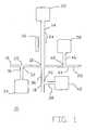
- FIG. 1illustrates a microfluidic device 1 for joining fluids according to an exemplary embodiment of the present invention.
- the microfluidic device 10includes a microfluidic junction 12, an outlet channel 14, and a plurality of circuit units 16, 18, 20.
- Outlet channel 14includes a first end connected with microfluidic junction 12, a second end connected with a waste reservoir 22, and an analysis region 24 positioned between the first and second ends of outlet channel 14.
- a sensor window 26can be positioned along analysis region 24.
- Circuit unit 16includes source channel 28, branch channel 30 and a flow diversion system.
- Source channel 28has a first end capable of receiving sample fluid and a second end connected with the junction 12.
- Branch channel 30is connected to source channel 28 at an intersection 32.
- Branch channel 30is further connected to a waste reservoir 34.
- a flow diversion systemis positioned at, near, or proximate to intersection 32, and is capable of differentially directing fluid flow through source channel 28 and into microfluidic junction 12 or into branch channel 30.
- Circuit unit 18includes source channel, 36, branch channel 38 and a flow diversion system.
- Source channel 36has a first end capable of receiving sample fluid and a second end connected with the junction 12.
- Branch channel 38is connected to source channel 36 at an intersection
- Branch channel 38is further connected to a waste reservoir 42.
- a flow diversion systemis positioned at, near, or proximate to intersection 40, and is capable of differentially directing fluid flow through source channel 36 and into microfluidic junction 12 or into branch channel 38.
- Circuit unit 20includes source channel 44, branch channel 46 and a flow diversion system.
- Source channel 44has a first end capable of receiving sample fluid and a second end connected with the junction 12.
- Branch channel 46is connected to source channel 44 at an intersection 48.
- Branch channel 46is further connected to a waste reservoir 50.
- a flow diversion systemis positioned at, near, or proximate to intersection 48, and is capable of differentially directing fluid flow through source channel 44 and into microfluidic junction 12 or into branch channel 46.
- Fluidsare respectively entered into circuit units 16, 18, 20. Fluid entered into the first end of source channel 28 flows to the intersection 32 and is directed either to continue through source channel 28 and into microfluidic junction 12 or into branch channel 30. Similarly, fluid entered into the first end of source channel 36 flows to the intersection 40 and is directed either to continue through source channel 36 and into microfluidic junction 12 or into branch channel 38. Likewise, fluid entered into the first end of source channel 44 flows to the intersection 48 and is directed either to continue through source channel 44 and into microfluidic junction 12 or into branch channel 46. Fluids directed toward the junction 12 converge in the junction 12 and flow into the outlet channel 14, through the analysis region 24 and into the waste reservoir 22.
- FIG. 2shows at least a portion of a microfluidic device 60.
- the device 60includes a microfluidic junction 62 having a plurality of junction inlets 64, 66, and 68 and an outlet channel 70.
- the plurality of junction inlets 64, 66, 68can each receive a fluid from respective source channels 72, 74, 78, connected thereto.
- Valved circuit units 78, 80, 82are shown.
- valves for use in controlling fluids in microfluidic deviceshave been developed and are contemplated for use in the present invention.
- U.S. Patent No. US 2002/148992filed April 3, 2002 , describes a pneumatic valve for use in laminated plastic microfluidic structures.
- a device for controlling flow in microfluidic devicesincluding a first substrate having at least one microfluidic structure manufactured therein, a first flexible sheet placed on top of at least a portion of the microfluidic structure, and a means for creating a pressure differential onto the first flexible sheet such that a portion of the sheet moves in relationship to the microfluidic structure wherein the cross-section of the microfluidic structure is altered at least in one dimension such that the fluid resistance in the microfluidic structure is altered.
- the described zero or low dead volume valveallows flow through microfluidic channels for use in mixing, dilution, particulate suspension and other techniques necessary for flow control in analytical devices.
- the valvesare pneumatic valves integrated into a cartridge constructed of multiple layers. Where a valve is in a "restricted” status, fluid flow past the valve is negligible. Where a valve is in an "unrestricted” status, fluid flows past the valve essentially unabated.
- pneumatic pressurecontrols whether the valve is in a restricted or unrestricted status. Pneumatic air lines deliver such pressure.
- Valved circuit unit 78includes source channel 72, branch channel 84, valve 86, and valve 88.
- Channel 72has a first end capable of receiving sample fluid and second end connected with junction 62.
- Valve 86is positioned at, near, or proximate to junction 62 and between the first end and second end of channel 72.
- Channel 84is connected with channel 72 at an intersection 90.
- Channel 84is also connected with channel 92.
- Valve 88is positioned along channel 84 at, near, or proximate to intersection 90. In operation, fluid entering channel 72 can flow into junction 62, into a channel 84 or continue flowing through channel 72 and into junction 62, or both, depending upon the status of valves 86 and 88.
- valve 86When valve 86 is restricted and valve 88 is unrestricted, entering fluid can fill channel 72 up to the position of valve 86. Fluid then can move into channel 84, past valve 88, and into channel 92. When valve 86 is unrestricted and valve 88 is restricted, entering fluid can move through the entire length of channel 72 and enter junction 62.
- valved circuit unit 80includes source channel 74, branch channel 94, valve 96, and valve 98.
- Channel 72has a first end capable of receiving sample fluid and second end connected with junction 62.
- Valve 96is positioned at, near, or proximate to junction 100 and between the first end and second end of channel 74.
- Channel 94is connected with channel 74 at an intersection 100.
- Channel 94is also connected with channel 92.
- Valve 98is positioned along channel 94 at, near, or proximate to intersection 100. In operation, fluid entering channel 74 can flow into junction 100, into a channel 94 or continue flowing through channel 74 and into junction 62, or both, depending upon the status of valves 96 and 98.
- valve 96When valve 96 is restricted and valve 98 is unrestricted, entering fluid can fill channel 74 up to the position of valve 96. Fluid then can move into channel 94, past valve 98, and into channel 92. When valve 96 is unrestricted and valve 98 is restricted, entering fluid can move through the entire length of channel 74 and enter junction 62.
- valved circuit unit 82includes source channel 76, branch channel 102, valve 104, and valve 106.
- Channel 76has a first end capable of receiving sample fluid and second end connected with junction 62.
- Valve 104is positioned at, near, or proximate to junction 108 and between the first end and second end of channel 76.
- Channel 102is connected with channel 76 at an intersection 108.
- Channel 102is also connected with channel 92.
- Valve 102is positioned along channel 102 at, near, or proximate to intersection 108. In operation, fluid entering channel 76 can flow into junction 108, into a channel 102 or continue flowing through channel 76 and into junction 62, or both, depending upon the status of valves 104 and 106.
- valve 104When valve 104 is restricted and valve 106 is unrestricted, entering fluid can fill channel 76 up to the position of valve 104. Fluid then can move into channel 102, past valve 106, and into channel 92. When valve 104 is unrestricted and valve 106 is restricted, entering fluid can move through the entire length of channel 76 and enter junction 62.
- a flow diversion systemcomprises valveless circuit units.
- Valveless circuit units containing valveless liquid microswitches, instead of valves,may be substituted for valved circuit units.
- U.S. patent No. 5, 726, 404assigned to Micronics, Inc., describes valveless liquid microswitches and teaches a valveless method and apparatus for high speed switching of liquid flow between intersecting microchannels.
- microfluidic junctionrefers to an area within a network of microfluidic channels where two or more channels join and fluids flowing through the interfacing channels may converge.
- microfluidic junction 62includes a microfluidic junction chamber 110, connects with outlet channel 70, and a plurality of inlets 64, 66, 68. Inlets 64, 66 and 68 are separated by intermediary regions 112, 114, respectively.
- fluidscan enter junction 62 through inlets 64, 66, and 68.
- d 1 and d 2the distance between wall 116 and region 112 increases when progressing from inlet 64 toward the center of microfluidic junction chamber 110.
- the distance between region 112 and region 114increases when progressing from inlet 66 toward the center of chamber 110.
- the velocity of this entering fluiddecreases as the fluid progresses from inlet 66 toward the center of chamber 25.
- the distance between region 114 and wall 118increases when progressing from inlet 68 toward the center of chamber 110.
- the velocity of this entering fluiddecreases as the fluid progresses from inlet 68 toward the center of chamber 110.
- the described geometrical arrangement of junction 62facilitates equal filling of chamber 110 and compensates for less than precise control over the timing of fluids entering through inlets 64, 66, 68.
- Fluids entering the microfluidic junction 62 from inlets 64, 66, 68converge along intermediary regions located between the respective junction inlets.
- the leading edge of fluid entering through inlet 64 and the leading edge of fluid entering through inlet 66converge along region 112 and the converged fluids fill chamber 110 beginning at region 112 and progressing toward the center of chamber 110.
- the leading edge of fluid entering through inlet 66 and the leading edge of fluid entering through inlet 68converge along region 114 and these converged fluids fill chamber 110 beginning at region 114 and progressing toward the center of chamber 110.
- Converged fluidscontinue filling chamber 110, then flow out of the microfluidic junction 62 through outlet channel 70. Convergence of multiple fluids and filling chamber 110 as described permits convergence of multiple fluids, minimizes gas voids, and facilitates laminar flow.
- an intermediary regionmay not be uniformly convex as shown in the embodiment of FIG. 2.
- an intermediary regionmay be angled at some position, such as to create an edge.
- the term "edge"describes the meeting of two linear surfaces, such as to create an angle of less than 180 degrees.
- a hydrophilic or hydrophobic materialcan be deposited along an intermediary region, depending upon whether the fluid to be deposited in the device is hydrophilic or hydrophobic. Similar to edges, hydrophobic material deposited in a channel causes an increase in surface tension in hydrophilic fluid flowing through the channel. Likewise, hydrophilic material deposited in a channel causes an increase in surface tension in hydrophobic fluid flowing through the channel. The increased resistance causes flowing fluid to stop until the driving pressure overcomes the surface tension resistance.
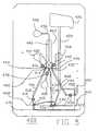
- FIG. 3shows a microfluidic device 200 that includes a microfluidic channel network as described in FIG. 1 contained within cartridge, according to another exemplary embodiment of the invention.
- the device 200includes a microfluidic junction 202 connected to a plurality of fluid ports 204, 206, 208.
- the ports 204, 206, 208 here shownare syringe filled fluid ports, but fluid ports that are filled by other means, such as by pipette, may alternatively be used.
- Source channels 210, 212, 214are positioned between microfluidic junction 202 and fluid ports 204, 206, and 208, respectively.
- Source channels 210, 212, 214respectively include fluid storage loops 216, 218, 220.
- Fluid storage loops 216, 218, 220allow on cartridge storage of a greater volume of fluids, but may not be present in alternative embodiments of the invention.
- Outlet channel 222has a first end connected with microfluidic junction 202 and a second end connected with waste reservoir 224, and an analysis region 226 positioned between reservoir 224 and junction 202.
- a sensor window 220may be positioned along a portion of a channel 222.
- Analysis region 226is an area designated for monitoring the interaction of fluids passing in a laminar fashion through a portion of channel 222.
- An analysis region 226provides for detection by any means known in the art, for example optical, electrical, pressure sensitive, or flow sensitive detection. More than one detection means can be employed in a single analysis region, for example optical and electrical.
- the cartridgecan include an electrical interconnect.
- the cartridgecan be electrically connected to electrical meanuring apparatus.
- a microfluidic devicecan include a sensor window 228 positioned over the analysis region for optical coupling with measuring apparatus such as light sources and photodetectors.
- the sensor windowscan be inserted glass or if the channel is formed in transparent sheets, the sheets themselves can serve as window.
- a sensor window 228may include an area of reduced thickness of the laminate cartridge.
- the optical detectioncan be absorption, luminescent, fluorescent or scattering based.
- a microfluidic devicecan comprise a plurality of analysis regions. Channel 230 is connected with a waste reservoir 224 and with valved circuit units 232, 234, 236, which are structured and operate as described above.
- fluidscan be entered into fluid ports 204, 206, 208 and flowed through device 200.
- Fluid entered into port 204flows into channel 210 and fills fluid storage loop 216.
- fluidmay be directed into channel 230 and overflow into waste reservoir 224 or may flow into junction 202.
- fluid entered into port 206flows into channel 212 and fills fluid storage loop 218.
- fluidmay be directed into channel 230 and overflow into waste reservoir 224 or may flow into junction 202.
- fluid entered into port 208flows into channel 214 and fills fluid storage loop 220.
- fluidmay be directed into channel 230 and overflow into waste reservoir 224 or may flow into junction 202.
- Fluids from fluid ports 204, 206, 208converge in junction 202 and flow through channel 222, through analysis region 226 and into waste reservoir 224.
- Pneumatic air lines 238 and 240are shown.
- FIG. 4shows a microfluidic device 300 that includes a microfluidic channel network, according to another embodiment of the invention.
- the microfluidic structure of device 300is shown contained within a cartridge.
- the device 300includes a microfluidic junction 302 connected to a plurality of fluid ports 304, 306, 308.
- the ports 304, 306, 308are designed for filling by pipette injection.
- Source channels 310, 312, 314are positioned between a microfluidic junction 302 and a plurality of fluid ports 304, 306, and 308, respectively.
- Channels 304, 306, 308respectively include valves 316, 318, 320 and fluid storage loops 322, 324, 326.
- Outlet channel 328has a first end connected with microfluidic junction 302 and a second end connected with waste reservoir 330, and an analysis region 332 positioned between thereof.
- a sensor window 334is positioned along a portion of channel 328.
- Channel 336is connected with a waste reservoir 338 and with valved circuit units 340, 342, 344, which are structured and operate as described above.
- fluidscan be entered into fluid ports 304, 306, 308 and flowed through device 300.
- Fluid entered into port 304flows into channel 310 up to valve 316. If valve 316 is restricted, flow does not continue; if valve 316 is unrestricted fluid continues flowing through channel 310 and into storage loop 322.
- fluidmay be directed into channel 336 and overflow into waste reservoir 338 or may flow into junction 302.
- fluid entered into port 306flows into channel 312 up to valve 318. If valve 318 is restricted, flow does not continue; if valve 318 is unrestricted fluid continues flowing through channel 312 and into storage loop 324.
- fluidmay be directed into channel 336 and overflow into waste reservoir 338 or may flow into junction 302.
- fluid entered into port 308flows into channel 314 up to valve 320. If valve 320 is restricted, flow does not continue; if valve 320 is unrestricted fluid continues flowing through channel 314 and into storage loop 326.
- fluidmay be directed into channel 336 and overflow into waste reservoir 338 or may flow into junction 302. Fluids from fluid ports 304, 306, 308 converge in junction 302 and flow through channel 328, past analysis region 332 and into waste reservoir 330. Pneumatic air lines 346, 348, 350 are shown.
- FIG. 5shows a microfluidic device 400 according to yet another embodiment of the invention.
- the microfluidic structure of device 400is shown contained within a cartridge.
- the device 400includes a microfluidic junction 402 connected to a plurality of fluid ports 404, 406, 408.
- the ports 404, 406, 408are pipette wells filled by pipette injection. Restriction of valve 410 allows deposition of fluid into port 404 without movement of the fluid into source channel 412. Fluid deposited in port 404 can flow past valves 410, 414 and into source channel 412, including fluid storage loop 416, and down to or past valve 418.
- Air, fluid or gas contained in the bottom portion of source channel 412can be cleared where valve 418 is restricted and valve 420 is unrestricted and fluid enters source channel 412 through source 422. Fluid entering from source 422 moves past valve 420, into channel 424 and overflows into waste reservoir 426. After air, fluid or gas is cleared, valves 410, 420 are restricted and valves 414, 418 unrestricted, and fluid in source channel 412 flows toward junction 402.
- restriction of valve 428allows deposition of fluid into port 406 without movement of the fluid into channel 430.
- Fluid deposited in port 406can flow past valves 428, 432 and into source channel 430, including fluid storage loop 434, and down to or past valve 436.
- Air, fluid or gas contained in the bottom portion of source channel 430can be cleared where valve 436 is restricted and valve 438 is unrestricted and fluid enters channel 430 through source 440. Fluid entering from source 440 moves past valve 438, into channel 424 and overflows into waste reservoir 426.
- valves 428, 438are restricted and valves 432, 436 unrestricted, and fluid in source channel 430 flows toward junction 402.
- restriction of valve 442allows deposition of fluid into port 408 without movement of the fluid into source channel 444. Fluid deposited in port 408 can flow past valves 442, 446 and into source channel 444, including fluid storage loop 448, and down to or past valve 450. Air, fluid or gas contained in the bottom portion of source channel 444 can be cleared where valve 450 is restricted and valve 452 is unrestricted and fluid enters channel 444 through source 454. Fluid entering from source 454 moves past valve 452, into channel 424 and overflows into waste reservoir 426. After air, fluid or gas is cleared, valves 442, 452 are restricted and valves 446, 450 unrestricted, and fluid in source channel 444 flows toward junction 404.
- Fluids deposited in ports 404, 406, 408flows through channels 412, 430, 444, respectively, and converge in junction 402. Converging fluids flow in a laminar manner through outlet channel 456 and into waste reservoir 458, including past analysis region 460.
- Sensor window 462is positioned along outlet channel 456. Pneumatic air lines 464, 466, 468, 470 are shown.
Landscapes
- Chemical & Material Sciences (AREA)
- Dispersion Chemistry (AREA)
- Physics & Mathematics (AREA)
- Health & Medical Sciences (AREA)
- Life Sciences & Earth Sciences (AREA)
- Analytical Chemistry (AREA)
- Biochemistry (AREA)
- General Health & Medical Sciences (AREA)
- General Physics & Mathematics (AREA)
- Immunology (AREA)
- Pathology (AREA)
- Automatic Analysis And Handling Materials Therefor (AREA)
- Apparatus Associated With Microorganisms And Enzymes (AREA)
- Physical Or Chemical Processes And Apparatus (AREA)
- Medicines Containing Material From Animals Or Micro-Organisms (AREA)
- Preparation Of Compounds By Using Micro-Organisms (AREA)
- Optical Measuring Cells (AREA)
- Optical Integrated Circuits (AREA)
Abstract
Description
- This invention relates to microfluidic devices and methods for performing analytical testing, and in particular, to a group of devices and methods that use microfluidic technology to join and analyze multiple fluids.
- Microfluidic devices are becoming increasingly popular for performing analytical testing. Tools developed by the semiconductor industry for miniaturizing electronics enable fabrication and inexpensive mass production of intricate fluid systems. Microfluidic systems are increasingly utilized in performing a variety of analytical techniques for the acquisition of information in multiple disciplines, including the medical field, life sciences, and drug discovery and development.
- There are different ways to manufacture microfluidic devices, including traditional lithographic techniques, soft lithography, and laminate technologies. In laminate fabrication the device consists of layers of material or lamina that have been cut, such as by a laser or stamp, into the desired shape and then held together with some form of adhesive, most commonly pressure-sensitive or thermally-activated adhesive. Maylar is commonly used, although other materials such as glass and polydimethylsiloxane (PDMS) have also been successfully incorporated into laminate devices. Microfluidic device construction may include a multi-layer laminated structure where each layer has channels and structures fabricated from a laminate material, forming microscale voids or channels where fluids flow. A microscale channel is generally defined as a fluid passage with at least one internal cross-sectional dimension that is less than 500 micrometers and typically between about 0.1 micrometers and about 500 micrometers. Either external pressurized fluid forced into the laminate or structures located within the laminate affect the control and pumping of fluids through these channels.
- Under microfluidic conditions, fluids usually flow in a very predictable, laminar fashion, thereby allowing multiple fluids to flow next to each other in the same channel without turbulent mixing or the need for physical separation by a membrane. This is known as the laminar fluid diffusion interface. Smaller particles typically diffuse quickly across the boundary layer, whereas large molecules and particles, such as cells, typically diffuse only minimally.
U.S. Patent No. 5,716,852 teaches a method for analyzing the presence and concentration of small particles in a flow cell using laminar flow and diffusion principles. Described is a channel cell system for detecting the presence of analyte particles in a sample stream using a laminar flow channel having at least two inlet means which provide an indicator stream and a sample stream, where the laminar flow channel has a depth sufficiently small to force laminar flow of the streams and length sufficient for diffusion of particles of the analyte into the indicator stream to form a detection area, and having an outlet out of the channel to form a single mixed stream. This device, which is known as a T-Sensor, may contain an external detecting means for detecting diffusion boundries in the indicator stream. This detecting means may be provided by any means known in the art, including optical means such as optical spectroscopy, or absorption spectroscopy of fluorescence.US 6 270 641 discloses a low dispersion device for joining two or more samples.- Special challenges arise in employing devices that utilize the laminar fluid diffusion interface because preservation and maintenance of laminar flow in these devices relies heavily on precisely timed and controlled, as well as reproducible, introduction of several fluids into one channel. For example, fluids moved through multiple channels may converge and may pass through a single channel in a laminar fashion. However, precisely controlling both the timing and the change in volume of fluids entering the junction is generally necessary to prevent fluids from first reaching the outlet channel or obstructing a neighboring inlet channel before converging with other fluids, both of which may disturb laminar flow. Thus, a means of converging multiple fluids as to produce consistent laminar flow while allowing the appropriate control over the timing and the change in volume of converging fluids is desirable.
- The invention concerns a microfluidic device and a method of converging and analysing fluids in accordance with claims 1 and 19 respectively. Preferred embodiments of the invention are described in the appended dependent claims.
- In one exemplary embodiment of the invention, the device comprises a microfluidic junction, an outlet channel, and a plurality of circuit units. A microfluidic junction is an area for converging multiple fluids. An outlet channel is capable of receiving fluid from the microfluidic junction. An outlet channel includes a first end connected with the microfluidic junction, a second end connected with a waste reservoir, and an analysis region positioned between the first end and the second end of the outlet channel. The device also includes a plurality of circuit units. Each circuit unit includes a source channel with a first end capable of receiving sample fluid and a second end connected with the microfluidic junction; a branch channel connected with the source channel at an intersection; and a flow diversion system capable of differentially directing fluid flowing through a source channel either into the microfluidic junction or into a branch channel.
- A microfluidic junction can include a chamber connected with an outlet channel and a plurality of inlets. The plurality of inlets are typically positioned along the chamber as to alow fluid to enter the chamber without obstructing neighboring inlets. In one example, the cross-sectional area of each inlet increases as progressing toward the center of the chamber. In another example, each inlet is separated by an intermediary region. An intermediary region, for example, may be uniformly convex or may comprise the meeting of two linear surfaces such as to create an edge. In another example, an intermediary region may contain either a hydrophobic or hydrophilic material deposited along its length.
- A circuit unit may comprise a valved circuit unit. A valved circuit unit is a circuit unit containing valves. For example, a valved circuit unit may have a first valve positioned along a branch channel of the circuit unit and a second valve positioned along a source channel of the circuit unit. The first and second valves are typically located at, near or proximate to the intersection of the branch channel and the source channel of a given circuit unit. In some instances, valves can be pneumatic valves.
- A circuit unit may also comprise a valveless circuit unit, or a circuit unit comprising valveless liquid microswitches.
- FIG. 1 shows a microfluidic channel network according to the invention;
- FIG. 2 illustrates a microfluidic channel network for performing a microfluidic process, in accordance with an embodiment of the invention;
- FIG. 3 shows a top view of a cartridge containing a microfluidic channel network for performing a microfluidic process, according to an embodiment of the invention;
- FIG. 4 shows a top view of a cartridge containing a microfluidic channel network for performing a microfluidic process, according to another embodiment of the invention; and
- FIG. 5 shows a top view of a cartridge containing a microfluidic channel network for performing a microfluidic process, according to yet another embodiment of the invention.
- The invention is illustrated by the following preferred embodiments. In the drawings, like numbers refer to like features, and the same number appearing in more than one drawing refers to the same feature. The members of the flow system of this invention that are "connected" are fluidically connected. The term "between" refers to the fluidic positioning, which does not necessarily correspond to the geometric positioning. The terms "top", "bottom" and "side" refer to the orientation in the drawings, which is not necessarily the orientation of the members in operation.
- The term "microfluidic" is generally defined as a substrate having a fluid passage with at least one internal cross-sectional dimension that is less than 500 micrometers and typically between about 0.1 micrometers and about 500 micrometers. The term "channel" as used herein, refers to a microfluidic channel and describes fluid elements dimensioned so that flow therein is substantially laminar.
- As used herein, the term "sample" is used in its broadest sense. Sample is meant to include any particles, chemicals, elements, cells, specimen or culture obtained from any source, including without limitation chemical, biological and environmental samples. Sample may be obtained from animals (including humans) and encompass fluids, solids, tissues, and gases. Biological samples include, without limitation, cells and any components thereof, blood products, such as plasma, serum and the like, proteins, peptides, amino acids, polynucleotide, lipids, carbohydrates, and any combinations thereof. The sample may include chemicals, either organic or inorganic, used to interact with the interactive material. When the interactive material contains biological material, for example, drugs, chemicals or other biological molecules may be added to the samples to cause a reaction or response by, among or within the biological material. Environmental samples include environmental material such as surface matter, soil, water, crystals and industrial samples.
- Channels and other microfluidic structures can be microfabricated in a substrate to produce a cartridge. As used herein, the term "cartridge" refers to a microfluidic device, which is typically, but not necessarily, disposable and which can be coupled with measurement, pumping, electronic, fluidic or other apparatus. The cartridge can be microfabricated using a variety of methods, including without limitation, traditional lithographic techniques, soft lithography, laminate technologies, etc. For example, the cartridge can be microfabricated from any moldable, machinable or etchable substrate. The term machining as used herein includes, without limitation printing, stamping, cutting and laser ablating. The cartridge can be formed in a single sheet, in a pair of sheets sandwiched together, or in a plurality of sheets laminated together. The term "sheet" refers to any solid substrate, flexible or otherwise. The channels can be etched in a silicon substrate and covered with a cover sheet, which can be a transparent cover sheet. In a multi-layer laminate embodiment, the channel walls are defined by removing material from at least one sheet, thus creating channels and voids, and positioning additional sheets on either side of the altered sheets. Any of the layers can contain fluid channels. In some cases the channel is simply a hole (or fluid via) to route the fluid to the next fluid laminate layer. Any two adjacent laminate layers may be bonded together to form a more complex single part.
- Electroosmotic and pressure driven flow are non-limiting examples of methods or systems for flow control. As used herein, the term "flow" refers to any type of movement of a liquid or solid through a microfluidic device or in a method according to the invention. Under microfluidic conditions fluid flow is characterized by a low Reynolds number and is predominately laminar, with any mixing of adjacent fluids being mainly by diffusion. Flow also includes, without limitation, any fluid stream as well as any material, cells or particles moving with, within, or against the fluid stream. Any type of force may be applied in order to provide a flow, including without limitation, pressure, capillary action, magnetic and electromagnetic force, electrophoresis, dielectrophoresis, electroosmosis, optical tweezers, and any combinations thereof.
- As used herein, the term "microfluidic junction" refers to an area within a network of microfluidic channels where a plurality of channels join and fluids flowing through the interfacing channels may converge. A microfluidic junction according to the present invention typically comprises a chamber connected with an outlet channel and a plurality of inlets. The plurality of inlets may be positioned along the chamber as to allow fluid to enter the chamber without obstructing neighboring inlets.
- The term "outlet channel" as used herein, refers to a channel capable of receiving fluid from the microfluidic junction. An outlet channel comprises a first end connected with a microfluidic junction, a second end connected with a waste reservoir, and an analysis region positioned between the first and second ends of the outlet channel. An analysis region is an area designated for monitoring the interaction of fluids passing through an outlet channel.
- As used herein, the term "circuit unit" refers to a series of interconnected channels through which fluid flow may be differentially restricted. A circuit unit comprises a source channel, a branch channel and a flow diversion system. A source channel has a first end capable of receiving sample fluid and a second end connected with a microfluidic junction. A branch channel of a circuit unit is connected with a source channel at an intersection. A flow diversion system is capable of differentially directing fluid flowing through a source channel into either the microfluidic junction or a branch channel, or both. A valved circuit unit, for example, is a circuit unit where the flow diversion system comprises at least two valves positioned at, near or proximate to the intersection of the source channel and the branch channel, and fluid flow is capable of being differentially restricted by the use of the valves.
- Figure 1 illustrates a microfluidic device 1 for joining fluids according to an exemplary embodiment of the present invention. The
microfluidic device 10 includes amicrofluidic junction 12, anoutlet channel 14, and a plurality ofcircuit units Outlet channel 14 includes a first end connected withmicrofluidic junction 12, a second end connected with awaste reservoir 22, and ananalysis region 24 positioned between the first and second ends ofoutlet channel 14. Asensor window 26 can be positioned alonganalysis region 24.Circuit unit 16 includessource channel 28,branch channel 30 and a flow diversion system.Source channel 28 has a first end capable of receiving sample fluid and a second end connected with thejunction 12.Branch channel 30 is connected to sourcechannel 28 at anintersection 32.Branch channel 30 is further connected to awaste reservoir 34. A flow diversion system is positioned at, near, or proximate tointersection 32, and is capable of differentially directing fluid flow throughsource channel 28 and intomicrofluidic junction 12 or intobranch channel 30. Similarly,Circuit unit 18 includes source channel, 36,branch channel 38 and a flow diversion system.Source channel 36 has a first end capable of receiving sample fluid and a second end connected with thejunction 12.Branch channel 38 is connected to sourcechannel 36 at anintersection Branch channel 38 is further connected to awaste reservoir 42. A flow diversion system is positioned at, near, or proximate tointersection 40, and is capable of differentially directing fluid flow throughsource channel 36 and intomicrofluidic junction 12 or intobranch channel 38. Likewise,Circuit unit 20 includessource channel 44,branch channel 46 and a flow diversion system.Source channel 44 has a first end capable of receiving sample fluid and a second end connected with thejunction 12.Branch channel 46 is connected to sourcechannel 44 at anintersection 48.Branch channel 46 is further connected to awaste reservoir 50. A flow diversion system is positioned at, near, or proximate tointersection 48, and is capable of differentially directing fluid flow throughsource channel 44 and intomicrofluidic junction 12 or intobranch channel 46. - The operation of the
microfluidic device 10 of FIG. 1 is now described. Fluids are respectively entered intocircuit units source channel 28 flows to theintersection 32 and is directed either to continue throughsource channel 28 and intomicrofluidic junction 12 or intobranch channel 30. Similarly, fluid entered into the first end ofsource channel 36 flows to theintersection 40 and is directed either to continue throughsource channel 36 and intomicrofluidic junction 12 or intobranch channel 38. Likewise, fluid entered into the first end ofsource channel 44 flows to theintersection 48 and is directed either to continue throughsource channel 44 and intomicrofluidic junction 12 or intobranch channel 46. Fluids directed toward thejunction 12 converge in thejunction 12 and flow into theoutlet channel 14, through theanalysis region 24 and into thewaste reservoir 22. - Another exemplary embodiment of the invention is described with reference to Figure 2, which shows at least a portion of a
microfluidic device 60. Thedevice 60 includes amicrofluidic junction 62 having a plurality ofjunction inlets outlet channel 70. The plurality ofjunction inlets respective source channels Valved circuit units - Many different types of valves for use in controlling fluids in microfluidic devices have been developed and are contemplated for use in the present invention. For example,
U.S. Patent No. US 2002/148992, filed April 3, 2002 , describes a pneumatic valve for use in laminated plastic microfluidic structures. Specifically described is a device for controlling flow in microfluidic devices including a first substrate having at least one microfluidic structure manufactured therein, a first flexible sheet placed on top of at least a portion of the microfluidic structure, and a means for creating a pressure differential onto the first flexible sheet such that a portion of the sheet moves in relationship to the microfluidic structure wherein the cross-section of the microfluidic structure is altered at least in one dimension such that the fluid resistance in the microfluidic structure is altered. The described zero or low dead volume valve allows flow through microfluidic channels for use in mixing, dilution, particulate suspension and other techniques necessary for flow control in analytical devices. - In one embodiment of the invention, the valves are pneumatic valves integrated into a cartridge constructed of multiple layers. Where a valve is in a "restricted" status, fluid flow past the valve is negligible. Where a valve is in an "unrestricted" status, fluid flows past the valve essentially unabated. In the operation and function of pneumatic valves, pneumatic pressure controls whether the valve is in a restricted or unrestricted status. Pneumatic air lines deliver such pressure.
Valved circuit unit 78 includessource channel 72,branch channel 84,valve 86, andvalve 88.Channel 72 has a first end capable of receiving sample fluid and second end connected withjunction 62.Valve 86 is positioned at, near, or proximate tojunction 62 and between the first end and second end ofchannel 72.Channel 84 is connected withchannel 72 at anintersection 90.Channel 84 is also connected withchannel 92.Valve 88 is positioned alongchannel 84 at, near, or proximate tointersection 90. In operation,fluid entering channel 72 can flow intojunction 62, into achannel 84 or continue flowing throughchannel 72 and intojunction 62, or both, depending upon the status ofvalves valve 86 is restricted andvalve 88 is unrestricted, entering fluid can fillchannel 72 up to the position ofvalve 86. Fluid then can move intochannel 84,past valve 88, and intochannel 92. Whenvalve 86 is unrestricted andvalve 88 is restricted, entering fluid can move through the entire length ofchannel 72 and enterjunction 62.- Similarly,
valved circuit unit 80 includessource channel 74,branch channel 94,valve 96, andvalve 98.Channel 72 has a first end capable of receiving sample fluid and second end connected withjunction 62.Valve 96 is positioned at, near, or proximate tojunction 100 and between the first end and second end ofchannel 74.Channel 94 is connected withchannel 74 at anintersection 100.Channel 94 is also connected withchannel 92.Valve 98 is positioned alongchannel 94 at, near, or proximate tointersection 100. In operation,fluid entering channel 74 can flow intojunction 100, into achannel 94 or continue flowing throughchannel 74 and intojunction 62, or both, depending upon the status ofvalves valve 96 is restricted andvalve 98 is unrestricted, entering fluid can fillchannel 74 up to the position ofvalve 96. Fluid then can move intochannel 94,past valve 98, and intochannel 92. Whenvalve 96 is unrestricted andvalve 98 is restricted, entering fluid can move through the entire length ofchannel 74 and enterjunction 62. - Likewise,
valved circuit unit 82 includessource channel 76, branch channel 102,valve 104, andvalve 106.Channel 76 has a first end capable of receiving sample fluid and second end connected withjunction 62.Valve 104 is positioned at, near, or proximate tojunction 108 and between the first end and second end ofchannel 76. Channel 102 is connected withchannel 76 at anintersection 108. Channel 102 is also connected withchannel 92. Valve 102 is positioned along channel 102 at, near, or proximate tointersection 108. In operation,fluid entering channel 76 can flow intojunction 108, into a channel 102 or continue flowing throughchannel 76 and intojunction 62, or both, depending upon the status ofvalves valve 104 is restricted andvalve 106 is unrestricted, entering fluid can fillchannel 76 up to the position ofvalve 104. Fluid then can move into channel 102,past valve 106, and intochannel 92. Whenvalve 104 is unrestricted andvalve 106 is restricted, entering fluid can move through the entire length ofchannel 76 and enterjunction 62. - In yet another embodiment of the invention, a flow diversion system comprises valveless circuit units. Valveless circuit units containing valveless liquid microswitches, instead of valves, may be substituted for valved circuit units. For example,
U.S. patent No. 5, 726, 404 , assigned to Micronics, Inc., describes valveless liquid microswitches and teaches a valveless method and apparatus for high speed switching of liquid flow between intersecting microchannels. - The term microfluidic junction refers to an area within a network of microfluidic channels where two or more channels join and fluids flowing through the interfacing channels may converge. In the exemplary embodiment of FIG. 2,
microfluidic junction 62 includes amicrofluidic junction chamber 110, connects withoutlet channel 70, and a plurality ofinlets Inlets intermediary regions - In operation, fluids can enter
junction 62 throughinlets wall 116 andregion 112 increases when progressing frominlet 64 toward the center ofmicrofluidic junction chamber 110. The velocity of a fluid flowing through a channel is related to the volume of the channel and is described as follows: Vetocity1/Vetocity2 = Area2/Area1. As fluid flows through a channel of increasing cross-sectional area, velocity decreases. As fluid entering throughinlet 64 fills the space betweenregion 112 andwall 116, the velocity of this entering fluid decreases as the fluid progresses frominlet 64 toward the center ofchamber 110. Similarly, the distance betweenregion 112 andregion 114 increases when progressing frominlet 66 toward the center ofchamber 110. As fluid entering throughinlet 66 fills the space betweenregions inlet 66 toward the center of chamber 25. Likewise, the distance betweenregion 114 andwall 118 increases when progressing frominlet 68 toward the center ofchamber 110. As fluid entering throughinlet 68 fills the space betweenregion 114 andwall 118, the velocity of this entering fluid decreases as the fluid progresses frominlet 68 toward the center ofchamber 110. The described geometrical arrangement ofjunction 62 facilitates equal filling ofchamber 110 and compensates for less than precise control over the timing of fluids entering throughinlets - Fluids entering the
microfluidic junction 62 frominlets inlet 64 and the leading edge of fluid entering throughinlet 66 converge alongregion 112 and the converged fluids fillchamber 110 beginning atregion 112 and progressing toward the center ofchamber 110. Likewise, the leading edge of fluid entering throughinlet 66 and the leading edge of fluid entering throughinlet 68 converge alongregion 114 and these converged fluids fillchamber 110 beginning atregion 114 and progressing toward the center ofchamber 110. Converged fluids continue fillingchamber 110, then flow out of themicrofluidic junction 62 throughoutlet channel 70. Convergence of multiple fluids and fillingchamber 110 as described permits convergence of multiple fluids, minimizes gas voids, and facilitates laminar flow. - In another exemplary embodiment of the invention, an intermediary region may not be uniformly convex as shown in the embodiment of FIG. 2. In another embodiment, an intermediary region may be angled at some position, such as to create an edge. The term "edge" describes the meeting of two linear surfaces, such as to create an angle of less than 180 degrees. Where a fluid moves within a channel due to a positive pressure upstream or a positive displacement, a concave meniscus is formed at the leading edge of the fluid flowing within the channel. When the fluid reaches a portion of the channel containing edges, the resistance against further flow increases and causes the fluid to stop and the meniscus to distend into the open space beyond the sharp edges until the driving pressure exceeds the force needed to overcome the surface tension resistance at the edges. When the force of the driving pressure overcomes the surface tension resistance, the fluid will flow into and thoroughly fill the space in the channel beyond the edges. In yet another embodiment, a hydrophilic or hydrophobic material can be deposited along an intermediary region, depending upon whether the fluid to be deposited in the device is hydrophilic or hydrophobic. Similar to edges, hydrophobic material deposited in a channel causes an increase in surface tension in hydrophilic fluid flowing through the channel. Likewise, hydrophilic material deposited in a channel causes an increase in surface tension in hydrophobic fluid flowing through the channel. The increased resistance causes flowing fluid to stop until the driving pressure overcomes the surface tension resistance.
- FIG. 3 shows a
microfluidic device 200 that includes a microfluidic channel network as described in FIG. 1 contained within cartridge, according to another exemplary embodiment of the invention. Thedevice 200 includes amicrofluidic junction 202 connected to a plurality offluid ports ports Source channels microfluidic junction 202 andfluid ports Source channels fluid storage loops Fluid storage loops Outlet channel 222 has a first end connected withmicrofluidic junction 202 and a second end connected withwaste reservoir 224, and ananalysis region 226 positioned betweenreservoir 224 andjunction 202. Asensor window 220 may be positioned along a portion of achannel 222.Analysis region 226 is an area designated for monitoring the interaction of fluids passing in a laminar fashion through a portion ofchannel 222. Ananalysis region 226 provides for detection by any means known in the art, for example optical, electrical, pressure sensitive, or flow sensitive detection. More than one detection means can be employed in a single analysis region, for example optical and electrical. For electrical detection, the cartridge can include an electrical interconnect. The cartridge can be electrically connected to electrical meanuring apparatus. For optical detection, a microfluidic device can include asensor window 228 positioned over the analysis region for optical coupling with measuring apparatus such as light sources and photodetectors. The sensor windows can be inserted glass or if the channel is formed in transparent sheets, the sheets themselves can serve as window. Where the microfluidic device is embodied in a laminate cartridge, asensor window 228 may include an area of reduced thickness of the laminate cartridge. The optical detection can be absorption, luminescent, fluorescent or scattering based. A microfluidic device can comprise a plurality of analysis regions.Channel 230 is connected with awaste reservoir 224 and withvalved circuit units - In operation, fluids can be entered into
fluid ports device 200. Fluid entered intoport 204 flows intochannel 210 and fillsfluid storage loop 216. Depending on the status of the valves of valved circuit unit 232, fluid may be directed intochannel 230 and overflow intowaste reservoir 224 or may flow intojunction 202. Similarly, fluid entered intoport 206 flows intochannel 212 and fillsfluid storage loop 218. Depending on the status of the valves ofvalved circuit unit 234, fluid may be directed intochannel 230 and overflow intowaste reservoir 224 or may flow intojunction 202. Likewise, fluid entered intoport 208 flows intochannel 214 and fillsfluid storage loop 220. Depending on the status of the valves ofvalved circuit unit 236, fluid may be directed intochannel 230 and overflow intowaste reservoir 224 or may flow intojunction 202. Fluids fromfluid ports junction 202 and flow throughchannel 222, throughanalysis region 226 and intowaste reservoir 224.Pneumatic air lines - FIG. 4 shows a
microfluidic device 300 that includes a microfluidic channel network, according to another embodiment of the invention. The microfluidic structure ofdevice 300 is shown contained within a cartridge. Thedevice 300 includes amicrofluidic junction 302 connected to a plurality offluid ports ports Source channels microfluidic junction 302 and a plurality offluid ports Channels valves fluid storage loops Outlet channel 328 has a first end connected withmicrofluidic junction 302 and a second end connected withwaste reservoir 330, and ananalysis region 332 positioned between thereof. Asensor window 334 is positioned along a portion ofchannel 328.Channel 336 is connected with awaste reservoir 338 and withvalved circuit units - In operation, fluids can be entered into
fluid ports device 300. Fluid entered intoport 304 flows intochannel 310 up tovalve 316. Ifvalve 316 is restricted, flow does not continue; ifvalve 316 is unrestricted fluid continues flowing throughchannel 310 and intostorage loop 322. Depending on the status of the valves ofvalved circuit unit 340, fluid may be directed intochannel 336 and overflow intowaste reservoir 338 or may flow intojunction 302. Similarly, fluid entered intoport 306 flows intochannel 312 up tovalve 318. Ifvalve 318 is restricted, flow does not continue; ifvalve 318 is unrestricted fluid continues flowing throughchannel 312 and intostorage loop 324. Depending on the status of the valves ofvalved circuit unit 342, fluid may be directed intochannel 336 and overflow intowaste reservoir 338 or may flow intojunction 302. Likewise, fluid entered intoport 308 flows intochannel 314 up tovalve 320. Ifvalve 320 is restricted, flow does not continue; ifvalve 320 is unrestricted fluid continues flowing throughchannel 314 and intostorage loop 326. Depending on the status of the valves ofvalved circuit unit 344, fluid may be directed intochannel 336 and overflow intowaste reservoir 338 or may flow intojunction 302. Fluids fromfluid ports junction 302 and flow throughchannel 328,past analysis region 332 and intowaste reservoir 330.Pneumatic air lines - FIG. 5 shows a
microfluidic device 400 according to yet another embodiment of the invention. The microfluidic structure ofdevice 400 is shown contained within a cartridge. Thedevice 400 includes amicrofluidic junction 402 connected to a plurality offluid ports ports valve 410 allows deposition of fluid intoport 404 without movement of the fluid intosource channel 412. Fluid deposited inport 404 can flowpast valves source channel 412, includingfluid storage loop 416, and down to orpast valve 418. Air, fluid or gas contained in the bottom portion ofsource channel 412 can be cleared wherevalve 418 is restricted andvalve 420 is unrestricted and fluid enterssource channel 412 throughsource 422. Fluid entering fromsource 422 movespast valve 420, intochannel 424 and overflows intowaste reservoir 426. After air, fluid or gas is cleared,valves valves source channel 412 flows towardjunction 402. - Similarly, restriction of
valve 428 allows deposition of fluid intoport 406 without movement of the fluid intochannel 430. Fluid deposited inport 406 can flowpast valves source channel 430, includingfluid storage loop 434, and down to orpast valve 436. Air, fluid or gas contained in the bottom portion ofsource channel 430 can be cleared wherevalve 436 is restricted andvalve 438 is unrestricted and fluid enterschannel 430 throughsource 440. Fluid entering fromsource 440 movespast valve 438, intochannel 424 and overflows intowaste reservoir 426. After air, fluid or gas is cleared,valves valves source channel 430 flows towardjunction 402. - Likewise, restriction of
valve 442 allows deposition of fluid intoport 408 without movement of the fluid intosource channel 444. Fluid deposited inport 408 can flowpast valves source channel 444, includingfluid storage loop 448, and down to orpast valve 450. Air, fluid or gas contained in the bottom portion ofsource channel 444 can be cleared wherevalve 450 is restricted andvalve 452 is unrestricted and fluid enterschannel 444 throughsource 454. Fluid entering fromsource 454 movespast valve 452, intochannel 424 and overflows intowaste reservoir 426. After air, fluid or gas is cleared,valves valves source channel 444 flows towardjunction 404. - Fluids deposited in
ports channels junction 402. Converging fluids flow in a laminar manner throughoutlet channel 456 and intowaste reservoir 458, includingpast analysis region 460.Sensor window 462 is positioned alongoutlet channel 456.Pneumatic air lines - It should be recognized that other arrangements, configurations and methods should be readily apparent to a person of ordinary skill in the art. Other embodiments, combinations and modifications of this invention will occur readily to those of ordinary skill in the art in view of these teachings. Therefore, this invention is to be limited only by the following claims.
Claims (29)
- A microfluidic device (10) for converging fluids, comprising:a. a microfluidic junction (12);b. an outlet channel (14) capable of receiving fluid from the microfluidic junction (12), said outlet channel (14) comprising a first end connected with the microfluidic junction (12), a second end connected with a waste reservoir (22), and an analysis region (24) positioned between said first end and said second end of the outlet channel (14); andc. a plurality of circuit units (16, 18, 20), each circuit unit comprising:i. a source channel (28, 36, 44) with a first end capable of receiving sample fluid and a second end connected with the microfluidic junction (12);
characterized in that,
said plurality of circuit units (16, 18, 20) each further comprises:ii. a branch channel (30, 38, 46) connected with the source channel (28, 36, 44) at an intersection; andiii. a flow diversion system capable of differentially directing fluid flowing through a source channel (28, 36, 44) either into the microfluidic junction (12) or into a branch channel (30, 38, 46). - The microfluidic device of claim 1, wherein said microfluidic junction comprises:a. a chamber connected with said outlet channel; andb. a plurality of inlets positioned along the chamber and capable of allowing fluid to enter the chamber without obstructing neighboring inlets, each of said inlets being separated from a neighboring inlet by an intermediary region.
- The microfluidic device of claim 2, wherein the cross-sectional area of each inlet increases as progressing toward the center of said chamber.
- The microfluidic device of claim 2, wherein each said intermediary region is uniformly convex.
- The microfluidic device of claim 2, wherein each intermediary region comprises two linear surfaces which meet to form an edge.
- The microfluidic device of claim 2, wherein a hydrophobic material is deposited along at least one intermediary region.
- The microfluidic device of claim 2, wherein a hydrophilic material is deposited along at least one intermediary region.
- The microfluidic device of claim 1, wherein at least one circuit unit is a valved circuit unit comprising a first valve positioned along a branch channel of said valved circuit unit and a second valve positioned along a source channel of said valved circuit unit, said first and second valves being located at, near or proximate to the intersection of said branch channel and said source channel.
- The microfluidic device.of claim 2, wherein at least one circuit unit is a valved circuit unit comprising a first valve positioned along a branch channel of said valved circuit unit and a second valve positioned along a source channel of said valved circuit unit, said first and second valves being located at, near or proximate to the intersection of said branch channel and said source channel.
- The microfluidic device of claim 1, wherein at least one circuit unit is a valveless circuit unit comprising a valveless liquid microswitch.
- The microfluidic device of claim 2, wherein at least one circuit unit is a valveless circuit unit comprising a valveless liquid microswitch.
- The microfluidic device of claim 2, further comprising a plurality of fluid ports for respectively introducing fluid into source channels of said plurality of circuit units, with at least one of said fluid ports being a syringe filled fluid port.
- The microfluidic device of claim 2, further comprising a plurality of fluid ports for respectively introducing fluid into source channels of said plurality of circuit units, with at least one of said fluid ports being a pipette injection port.
- The microfluidic device of claim 2, further comprising a plurality of fluid ports for respectively introducing fluid into source channels of said plurality of circuit units, with at least one of said fluid ports being a pipette well filled by pipette injection.
- The microfluidic device of claim 12, further comprising at least one valve positioned along a source channel, said valve being located between the microfluidic junction and a fluid port.
- The microfluidic device of claim 13, further comprising at least one valve positioned along a source channel, said valve being located between the microfluidic junction and a fluid port.
- The microfluidic device of claim 14, further comprising at least one valve positioned along a source channel, said valve being located between the microfluidic junction and a fluid port.
- The microfluidic device of claim 2, wherein said microfluidic junction, outlet channel and plurality of circuit units are contained within a plurality of laminate layers.
- A method of converging and analyzing fluids, comprising:a. providing a microfluidic device (10); comprising :i. a microfluidic junction (22) ;ii. an outlet channel (14) capable of receiving fluid from the microfluidic junction (12), said outlet channel (14) comprising a first end connected with the microfluidic junction (12), a second end connected with a waste reservoir (22), and an analysis region (24) positioned between said first end and said second end of the outlet channel (14).iii. a plurality of circuit units (16, 18, 20), each circuit unit comprising:1. a source channel (28, 36, 44) with a first end capable of receiving sample fluid and end connected with the microfluidic junction (12); and2. a branch channel (30, 38, 46) connected with the source channel (28, 36, 44) at an intersection (32, 40, 48) ;3. a flow diversion system capable of differentially directing fluid flowing through a source channel (28, 36, 44) either into the microfluidic junction (12) or into a branch channel (30, 38, 46);b. introducing fluids into the respective source channels (28, 36, 44) of circuit units (16, 18, 20) of the microfluidic device ;c. flowing fluids into the microfluidic junction (12) of the device; andd. flowing fluids through the outlet channel (14) of the microfluidic device (10).
- The method of claim 19, wherein the microfluidic junction of said device comprises:a. a chamber connected with said outlet channel; andb. a plurality of inlets positioned along the chamber and capable of allowing fluid to enter the chamber without obstructing neighboring inlets, each of said inlets being separated from a neighboring inlet by an intermediary region.
- The method of claim 20, wherein the cross-sectional area of each said inlet increases as progressing toward the center of said chamber.
- The method of claim 20, wherein each said intermediary region is uniformly convex.
- The method of claim 20, wherein each intermediary region comprises two linear surfaces which meet to form an edge.
- The method of claim 20, wherein a hydrophobic material is deposited along at least one intermediary region.
- The method of claim 20, wherein a hydrophilic material is deposited along at least one intermediary region.
- The method of claim 19, wherein at least one circuit unit is a valved circuit unit comprising a first valve positioned along a branch channel of said valved circuit unit and a second valve positioned along a source channel of said valved circuit unit, said first and second valves being located at, near or proximate to the intersection of said branch channel and said source channel.
- The method of claim 20, wherein at least one circuit unit is a valved circuit unit comprising a first valve positioned along a branch channel of said valved circuit unit and a second valve positioned along a source channel of said valved circuit unit, said first and second valves being located at, near or proximate to the intersection of said branch channel and said source channel.
- The method of claim 19, wherein at least one circuit unit is a valveless circuit unit comprising a valveless liquid microswitch.
- The method of claim 20, wherein at least one circuit unit is a valveless circuit unit comprising a valveless liquid microswitch.
Applications Claiming Priority (3)
| Application Number | Priority Date | Filing Date | Title |
|---|---|---|---|
| US36434302P | 2002-03-14 | 2002-03-14 | |
| US364343P | 2002-03-14 | ||
| PCT/US2003/007226WO2003078065A1 (en) | 2002-03-14 | 2003-03-10 | Microfluidic channel network device |
Publications (2)
| Publication Number | Publication Date |
|---|---|
| EP1487581A1 EP1487581A1 (en) | 2004-12-22 |
| EP1487581B1true EP1487581B1 (en) | 2007-08-22 |
Family
ID=28041902
Family Applications (2)
| Application Number | Title | Priority Date | Filing Date |
|---|---|---|---|
| EP03716414AExpired - LifetimeEP1487581B1 (en) | 2002-03-14 | 2003-03-10 | Microfluidic channel network device |
| EP03744624AExpired - LifetimeEP1483564B1 (en) | 2002-03-14 | 2003-03-10 | Ribbon flow cytometry and cell sorting |
Family Applications After (1)
| Application Number | Title | Priority Date | Filing Date |
|---|---|---|---|
| EP03744624AExpired - LifetimeEP1483564B1 (en) | 2002-03-14 | 2003-03-10 | Ribbon flow cytometry and cell sorting |
Country Status (7)
| Country | Link |
|---|---|
| US (1) | US7223371B2 (en) |
| EP (2) | EP1487581B1 (en) |
| JP (2) | JP2005519751A (en) |
| AT (2) | ATE370787T1 (en) |
| AU (1) | AU2003220121A1 (en) |
| DE (2) | DE60311968T2 (en) |
| WO (2) | WO2003078065A1 (en) |
Families Citing this family (178)
| Publication number | Priority date | Publication date | Assignee | Title |
|---|---|---|---|---|
| EP2264428B1 (en) | 1997-01-31 | 2017-05-03 | Xy, Llc | Optical apparatus with focussing reflector for converging radiation onto a flow of particles |
| US6071689A (en) | 1997-12-31 | 2000-06-06 | Xy, Inc. | System for improving yield of sexed embryos in mammals |
| US6149867A (en) | 1997-12-31 | 2000-11-21 | Xy, Inc. | Sheath fluids and collection systems for sex-specific cytometer sorting of sperm |
| US7208265B1 (en) | 1999-11-24 | 2007-04-24 | Xy, Inc. | Method of cryopreserving selected sperm cells |
| CA2822983C (en) | 2000-11-29 | 2017-05-09 | Xy, Llc | System to separate frozen-thawed spermatozoa into x-chromosome bearing and y-chromosome bearing populations |
| US7713687B2 (en) | 2000-11-29 | 2010-05-11 | Xy, Inc. | System to separate frozen-thawed spermatozoa into x-chromosome bearing and y-chromosome bearing populations |
| US7829025B2 (en) | 2001-03-28 | 2010-11-09 | Venture Lending & Leasing Iv, Inc. | Systems and methods for thermal actuation of microfluidic devices |
| US8895311B1 (en) | 2001-03-28 | 2014-11-25 | Handylab, Inc. | Methods and systems for control of general purpose microfluidic devices |
| US20040109793A1 (en)* | 2002-02-07 | 2004-06-10 | Mcneely Michael R | Three-dimensional microfluidics incorporating passive fluid control structures |
| US11243494B2 (en) | 2002-07-31 | 2022-02-08 | Abs Global, Inc. | Multiple laminar flow-based particle and cellular separation with laser steering |
| EP2284256A3 (en) | 2002-08-01 | 2012-08-29 | Xy, Llc | Low pressure sperm separation system |
| US8486618B2 (en) | 2002-08-01 | 2013-07-16 | Xy, Llc | Heterogeneous inseminate system |
| MXPA05001654A (en) | 2002-08-15 | 2005-10-18 | Xy Inc | High resolution flow cytometer. |
| US7169548B2 (en) | 2002-09-13 | 2007-01-30 | Xy, Inc. | Sperm cell processing and preservation systems |
| US7329545B2 (en) | 2002-09-24 | 2008-02-12 | Duke University | Methods for sampling a liquid flow |
| US6911132B2 (en) | 2002-09-24 | 2005-06-28 | Duke University | Apparatus for manipulating droplets by electrowetting-based techniques |
| CA2500392C (en) | 2002-09-27 | 2012-11-27 | The General Hospital Corporation | Microfluidic device for cell separation and uses thereof |
| MX350776B (en) | 2003-03-28 | 2017-09-15 | Inguran Llc * | Apparatus, methods and processes for sorting particles and for providing sex-sorted animal sperm. |
| DE10320870A1 (en) | 2003-05-09 | 2004-12-09 | Evotec Technologies Gmbh | Particle injector for a cell sorter |
| NZ544103A (en) | 2003-05-15 | 2010-10-29 | Xy Llc | Efficient haploid cell sorting for flow cytometer systems |
| EP2407243B1 (en) | 2003-07-31 | 2020-04-22 | Handylab, Inc. | Multilayered microfluidic device |
| US20050047967A1 (en)* | 2003-09-03 | 2005-03-03 | Industrial Technology Research Institute | Microfluidic component providing multi-directional fluid movement |
| KR20060134942A (en) | 2003-10-30 | 2006-12-28 | 사이토놈, 인크. | Multilayer Hydrodynamic Sheath Flow Structure |
| WO2005075958A1 (en)* | 2004-02-04 | 2005-08-18 | Evotec Technologies Gmbh | Microfluidic system and associated operational method |
| NZ550196A (en) | 2004-03-29 | 2010-11-26 | Inguran Llc | Method for sorting sperm cells into X or Y chromosome-bearing enriched populations comprising a composition which inhibits motility and a DNA-selective dye |
| US8852862B2 (en) | 2004-05-03 | 2014-10-07 | Handylab, Inc. | Method for processing polynucleotide-containing samples |
| AU2005266930B2 (en) | 2004-07-22 | 2010-09-16 | Inguran, Llc | Process for enriching a population of sperm cells |
| JP4279754B2 (en)* | 2004-09-13 | 2009-06-17 | アルプス電気株式会社 | Plate and inspection method using the plate |
| DE102004047953A1 (en)* | 2004-10-01 | 2006-04-20 | Rudolf Rigler | Selection of particle possessing predetermined property from population encompassing multiplicity of different particles, comprises providing population of different particles, and labeling particles which possess predetermined property |
| US9132398B2 (en) | 2007-10-12 | 2015-09-15 | Rheonix, Inc. | Integrated microfluidic device and methods |
| KR101198038B1 (en)* | 2005-01-28 | 2012-11-06 | 듀크 유니버서티 | Apparatuses and methods for manipulating droplets on a printed circuit board |
| US20070196820A1 (en) | 2005-04-05 | 2007-08-23 | Ravi Kapur | Devices and methods for enrichment and alteration of cells and other particles |
| US7740804B2 (en)* | 2005-04-12 | 2010-06-22 | Chromedx Inc. | Spectroscopic sample holder |
| CA2507323A1 (en)* | 2005-05-13 | 2006-11-13 | Chromedx Inc. | Diagnostic whole blood and plasma apparatus |
| US20100245803A1 (en)* | 2005-04-12 | 2010-09-30 | Chromedx Inc. | Blood sample holder for spectroscopic analysis |
| US8206650B2 (en)* | 2005-04-12 | 2012-06-26 | Chromedx Inc. | Joint-diagnostic spectroscopic and biosensor meter |
| CA2517299A1 (en)* | 2005-08-26 | 2007-02-26 | Chromedx Inc. | Hollow needle assembly |
| WO2006119806A1 (en)* | 2005-05-13 | 2006-11-16 | Agilent Technologies, Inc. | Fluid cell with sheath flow |
| TWI253435B (en)* | 2005-06-13 | 2006-04-21 | Univ Chung Yuan Christian | Loop micro fluid system |
| US8273294B2 (en)* | 2005-07-01 | 2012-09-25 | Honeywell International Inc. | Molded cartridge with 3-D hydrodynamic focusing |
| US9354156B2 (en) | 2007-02-08 | 2016-05-31 | Emd Millipore Corporation | Microfluidic particle analysis method, device and system |
| US9260688B2 (en)* | 2005-07-07 | 2016-02-16 | The Regents Of The University Of California | Methods and apparatus for cell culture array |
| US8257964B2 (en) | 2006-01-04 | 2012-09-04 | Cell ASIC | Microwell cell-culture device and fabrication method |
| US9388374B2 (en) | 2005-07-07 | 2016-07-12 | Emd Millipore Corporation | Microfluidic cell culture systems |
| US9637715B2 (en) | 2005-07-07 | 2017-05-02 | Emd Millipore Corporation | Cell culture and invasion assay method and system |
| US8921102B2 (en) | 2005-07-29 | 2014-12-30 | Gpb Scientific, Llc | Devices and methods for enrichment and alteration of circulating tumor cells and other particles |
| US7731910B2 (en)* | 2005-08-05 | 2010-06-08 | Hewlett-Packard Development Company, L.P. | Microfluidic mixing assembly |
| US9056291B2 (en) | 2005-11-30 | 2015-06-16 | Micronics, Inc. | Microfluidic reactor system |
| US7763453B2 (en) | 2005-11-30 | 2010-07-27 | Micronics, Inc. | Microfluidic mixing and analytic apparatus |
| US8616048B2 (en)* | 2006-02-02 | 2013-12-31 | E I Spectra, LLC | Reusable thin film particle sensor |
| US9452429B2 (en) | 2006-02-02 | 2016-09-27 | E. I. Spectra, Llc | Method for mutiplexed microfluidic bead-based immunoassay |
| US9293311B1 (en) | 2006-02-02 | 2016-03-22 | E. I. Spectra, Llc | Microfluidic interrogation device |
| US20110189714A1 (en)* | 2010-02-03 | 2011-08-04 | Ayliffe Harold E | Microfluidic cell sorter and method |
| US8072603B2 (en) | 2006-02-02 | 2011-12-06 | E I Spectra, LLC | Fluorescence-activated cell detector |
| JP2007225438A (en)* | 2006-02-23 | 2007-09-06 | Konica Minolta Medical & Graphic Inc | Microfluid chip |
| WO2007106580A2 (en) | 2006-03-15 | 2007-09-20 | Micronics, Inc. | Rapid magnetic flow assays |
| US7569789B2 (en)* | 2006-03-16 | 2009-08-04 | Visiongate, Inc. | Cantilevered coaxial flow injector apparatus and method for sorting particles |
| US10900066B2 (en) | 2006-03-24 | 2021-01-26 | Handylab, Inc. | Microfluidic system for amplifying and detecting polynucleotides in parallel |
| WO2007112114A2 (en) | 2006-03-24 | 2007-10-04 | Handylab, Inc. | Integrated system for processing microfluidic samples, and method of using same |
| US11806718B2 (en) | 2006-03-24 | 2023-11-07 | Handylab, Inc. | Fluorescence detector for microfluidic diagnostic system |
| US7998708B2 (en)* | 2006-03-24 | 2011-08-16 | Handylab, Inc. | Microfluidic system for amplifying and detecting polynucleotides in parallel |
| US8883490B2 (en) | 2006-03-24 | 2014-11-11 | Handylab, Inc. | Fluorescence detector for microfluidic diagnostic system |
| US20080050739A1 (en) | 2006-06-14 | 2008-02-28 | Roland Stoughton | Diagnosis of fetal abnormalities using polymorphisms including short tandem repeats |
| US8137912B2 (en) | 2006-06-14 | 2012-03-20 | The General Hospital Corporation | Methods for the diagnosis of fetal abnormalities |
| EP2589668A1 (en) | 2006-06-14 | 2013-05-08 | Verinata Health, Inc | Rare cell analysis using sample splitting and DNA tags |
| WO2007147074A2 (en) | 2006-06-14 | 2007-12-21 | Living Microsystems, Inc. | Use of highly parallel snp genotyping for fetal diagnosis |
| EP2041573B1 (en)* | 2006-06-23 | 2019-09-04 | PerkinElmer Health Sciences, Inc. | Methods and devices for microfluidic point-of-care immunoassays |
| WO2008147382A1 (en)* | 2006-09-27 | 2008-12-04 | Micronics, Inc. | Integrated microfluidic assay devices and methods |
| WO2008061165A2 (en) | 2006-11-14 | 2008-05-22 | Handylab, Inc. | Microfluidic cartridge and method of making same |
| US8262900B2 (en)* | 2006-12-14 | 2012-09-11 | Life Technologies Corporation | Methods and apparatus for measuring analytes using large scale FET arrays |
| US11339430B2 (en) | 2007-07-10 | 2022-05-24 | Life Technologies Corporation | Methods and apparatus for measuring analytes using large scale FET arrays |
| CA2672315A1 (en) | 2006-12-14 | 2008-06-26 | Ion Torrent Systems Incorporated | Methods and apparatus for measuring analytes using large scale fet arrays |
| US20080245740A1 (en)* | 2007-01-29 | 2008-10-09 | Searete Llc, A Limited Liability Corporation Of The State Of Delaware | Fluidic methods |
| EP2134471A2 (en) | 2007-04-06 | 2009-12-23 | California Institute of Technology | Microfluidic device |
| JP4911514B2 (en)* | 2007-05-14 | 2012-04-04 | 独立行政法人産業技術総合研究所 | Microchip, liquid dispensing method |
| US9186677B2 (en) | 2007-07-13 | 2015-11-17 | Handylab, Inc. | Integrated apparatus for performing nucleic acid extraction and diagnostic testing on multiple biological samples |
| US8182763B2 (en) | 2007-07-13 | 2012-05-22 | Handylab, Inc. | Rack for sample tubes and reagent holders |
| EP3222733B1 (en) | 2007-07-13 | 2021-04-07 | Handylab, Inc. | Polynucleotide capture materials, and methods of using same |
| US8105783B2 (en) | 2007-07-13 | 2012-01-31 | Handylab, Inc. | Microfluidic cartridge |
| US8287820B2 (en) | 2007-07-13 | 2012-10-16 | Handylab, Inc. | Automated pipetting apparatus having a combined liquid pump and pipette head system |
| WO2009018473A1 (en)* | 2007-07-31 | 2009-02-05 | Micronics, Inc. | Sanitary swab collection system, microfluidic assay device, and methods for diagnostic assays |
| US8268246B2 (en) | 2007-08-09 | 2012-09-18 | Advanced Liquid Logic Inc | PCB droplet actuator fabrication |
| US8015887B2 (en)* | 2007-09-29 | 2011-09-13 | E I Spectra, LLC | Instrumented pipette tip |
| WO2009070246A1 (en)* | 2007-11-27 | 2009-06-04 | E.I Spectra, Llc | Fluorescence-based pipette instrument |
| EP3173787B1 (en) | 2008-01-03 | 2021-06-02 | EMD Millipore Corporation | Cell culture array system for automated assays and methods of operation and manufacture thereof |
| JP5303028B2 (en) | 2008-04-07 | 2013-10-02 | イーアイ・スペクトラ・エルエルシー | Manufacturing method of microfluidic sensor |
| US8961902B2 (en)* | 2008-04-23 | 2015-02-24 | Bioscale, Inc. | Method and apparatus for analyte processing |
| JP2010169701A (en)* | 2008-05-13 | 2010-08-05 | Sony Corp | Microchip |
| JP4661942B2 (en)* | 2008-05-13 | 2011-03-30 | ソニー株式会社 | Microchip and its channel structure |
| WO2010033578A2 (en) | 2008-09-20 | 2010-03-25 | The Board Of Trustees Of The Leland Stanford Junior University | Noninvasive diagnosis of fetal aneuploidy by sequencing |
| US20100301398A1 (en) | 2009-05-29 | 2010-12-02 | Ion Torrent Systems Incorporated | Methods and apparatus for measuring analytes |
| US11951474B2 (en) | 2008-10-22 | 2024-04-09 | Life Technologies Corporation | Fluidics systems for sequential delivery of reagents |
| US20100137143A1 (en) | 2008-10-22 | 2010-06-03 | Ion Torrent Systems Incorporated | Methods and apparatus for measuring analytes |
| US8546128B2 (en) | 2008-10-22 | 2013-10-01 | Life Technologies Corporation | Fluidics system for sequential delivery of reagents |
| US8776573B2 (en) | 2009-05-29 | 2014-07-15 | Life Technologies Corporation | Methods and apparatus for measuring analytes |
| WO2012109612A2 (en)* | 2011-02-11 | 2012-08-16 | Code Footwear, Llc | Reconfigurable apparel manufacture and business processes |
| US9353342B2 (en) | 2010-01-21 | 2016-05-31 | Emd Millipore Corporation | Cell culture and gradient migration assay methods and devices |
| CN102740976B (en) | 2010-01-29 | 2016-04-20 | 精密公司 | Sample-Response Microfluidic Cartridges |
| US10787701B2 (en) | 2010-04-05 | 2020-09-29 | Prognosys Biosciences, Inc. | Spatially encoded biological assays |
| HUE026666T2 (en) | 2010-04-05 | 2016-07-28 | Prognosys Biosciences Inc | Spatially encoded biological assays |
| US20190300945A1 (en) | 2010-04-05 | 2019-10-03 | Prognosys Biosciences, Inc. | Spatially Encoded Biological Assays |
| WO2012003363A1 (en) | 2010-06-30 | 2012-01-05 | Life Technologies Corporation | Ion-sensing charge-accumulation circuits and methods |
| JP2013540259A (en) | 2010-06-30 | 2013-10-31 | ライフ テクノロジーズ コーポレーション | Array column integrator |
| TWI539172B (en) | 2010-06-30 | 2016-06-21 | 生命技術公司 | Methods and apparatus for testing isfet arrays |
| US11307166B2 (en) | 2010-07-01 | 2022-04-19 | Life Technologies Corporation | Column ADC |
| EP2589065B1 (en) | 2010-07-03 | 2015-08-19 | Life Technologies Corporation | Chemically sensitive sensor with lightly doped drains |
| WO2012027391A1 (en)* | 2010-08-23 | 2012-03-01 | Life Technologies Corporation | Temperature control of chemical detection system |
| WO2012036679A1 (en) | 2010-09-15 | 2012-03-22 | Life Technologies Corporation | Methods and apparatus for measuring analytes |
| US10908066B2 (en) | 2010-11-16 | 2021-02-02 | 1087 Systems, Inc. | Use of vibrational spectroscopy for microfluidic liquid measurement |
| US10526572B2 (en) | 2011-04-01 | 2020-01-07 | EMD Millipore Corporaticn | Cell culture and invasion assay method and system |
| GB201106254D0 (en) | 2011-04-13 | 2011-05-25 | Frisen Jonas | Method and product |
| CN106190806B (en) | 2011-04-15 | 2018-11-06 | 贝克顿·迪金森公司 | Scan real-time microfluid thermal cycler and the method for synchronous thermal cycle and scanning optical detection |
| DE102011076051A1 (en) | 2011-05-18 | 2012-11-22 | Siemens Aktiengesellschaft | Magnetophoretic analyte selection and enrichment |
| WO2013067202A1 (en) | 2011-11-04 | 2013-05-10 | Handylab, Inc. | Polynucleotide sample preparation device |
| US9970984B2 (en) | 2011-12-01 | 2018-05-15 | Life Technologies Corporation | Method and apparatus for identifying defects in a chemical sensor array |
| ES2870857T3 (en) | 2011-12-03 | 2021-10-27 | Emd Millipore Corp | Microfluidic system for cell culture |
| CN104136123B (en) | 2012-01-09 | 2017-03-01 | 精密公司 | Microfluidic reactor system |
| EP2810080B1 (en) | 2012-02-03 | 2024-03-27 | Becton, Dickinson and Company | External files for distribution of molecular diagnostic tests and determination of compatibility between tests |
| US8804105B2 (en) | 2012-03-27 | 2014-08-12 | E. I. Spectra, Llc | Combined optical imaging and electrical detection to characterize particles carried in a fluid |
| US8786331B2 (en) | 2012-05-29 | 2014-07-22 | Life Technologies Corporation | System for reducing noise in a chemical sensor array |
| WO2014060483A1 (en) | 2012-10-17 | 2014-04-24 | Spatial Transcriptomics Ab | Methods and product for optimising localised or spatial detection of gene expression in a tissue sample |
| JP1628116S (en) | 2012-10-24 | 2019-04-01 | ||
| US20140322706A1 (en) | 2012-10-24 | 2014-10-30 | Jon Faiz Kayyem | Integrated multipelx target analysis |
| JP6298474B2 (en) | 2012-12-17 | 2018-03-20 | レウコドゥックス,リミテッド | Systems and methods for detecting biological conditions |
| US10610861B2 (en)* | 2012-12-17 | 2020-04-07 | Accellix Ltd. | Systems, compositions and methods for detecting a biological condition |
| US20140170678A1 (en) | 2012-12-17 | 2014-06-19 | Leukodx Ltd. | Kits, compositions and methods for detecting a biological condition |
| JP6498125B2 (en) | 2012-12-21 | 2019-04-10 | マイクロニクス, インコーポレイテッド | Fluid circuit and associated manufacturing method |
| WO2014100743A2 (en) | 2012-12-21 | 2014-06-26 | Micronics, Inc. | Low elasticity films for microfluidic use |
| WO2014100725A1 (en) | 2012-12-21 | 2014-06-26 | Micronics, Inc. | Portable fluorescence detection system and microassay cartridge |
| US9080968B2 (en) | 2013-01-04 | 2015-07-14 | Life Technologies Corporation | Methods and systems for point of use removal of sacrificial material |
| US9841398B2 (en) | 2013-01-08 | 2017-12-12 | Life Technologies Corporation | Methods for manufacturing well structures for low-noise chemical sensors |
| CN103191791B (en)* | 2013-03-01 | 2014-09-10 | 东南大学 | Integrated chip system for high-throughput sorting and counting detection of biological particles, and application |
| US8963216B2 (en) | 2013-03-13 | 2015-02-24 | Life Technologies Corporation | Chemical sensor with sidewall spacer sensor surface |
| CN105283753B (en) | 2013-03-14 | 2020-07-10 | 塞通诺米/St有限责任公司 | Hydrodynamic focusing apparatus and method |
| EP2972280B1 (en) | 2013-03-15 | 2021-09-29 | Life Technologies Corporation | Chemical sensor with consistent sensor surface areas |
| CN107866286A (en) | 2013-03-15 | 2018-04-03 | 金马克诊断股份有限公司 | Systems, methods, and apparatus for manipulating deformable fluid containers |
| JP6671274B2 (en) | 2013-03-15 | 2020-03-25 | ライフ テクノロジーズ コーポレーション | Chemical device with thin conductive element |
| US9835585B2 (en) | 2013-03-15 | 2017-12-05 | Life Technologies Corporation | Chemical sensor with protruded sensor surface |
| CA2911303C (en) | 2013-05-07 | 2021-02-16 | Micronics, Inc. | Methods for preparation of nucleic acid-containing samples using clay minerals and alkaline solutions |
| EP2994750B1 (en) | 2013-05-07 | 2020-08-12 | PerkinElmer Health Sciences, Inc. | Microfluidic devices and methods for performing serum separation and blood cross-matching |
| CA2911308C (en) | 2013-05-07 | 2021-10-19 | Micronics, Inc. | Device for preparation and analysis of nucleic acids |
| US20140336063A1 (en) | 2013-05-09 | 2014-11-13 | Life Technologies Corporation | Windowed Sequencing |
| US10458942B2 (en) | 2013-06-10 | 2019-10-29 | Life Technologies Corporation | Chemical sensor array having multiple sensors per well |
| CN105849275B (en) | 2013-06-25 | 2020-03-17 | 普罗格诺西斯生物科学公司 | Method and system for detecting spatial distribution of biological targets in a sample |
| US8961904B2 (en) | 2013-07-16 | 2015-02-24 | Premium Genetics (Uk) Ltd. | Microfluidic chip |
| WO2015009284A1 (en)* | 2013-07-16 | 2015-01-22 | Premium Genetics (Uk) Ltd. | Microfluidic chip |
| WO2015010127A1 (en)* | 2013-07-19 | 2015-01-22 | Advanced Liquid Logic, Inc. | Methods of on-actuator temperature measuremment |
| GB2516669B (en)* | 2013-07-29 | 2015-09-09 | Atlas Genetics Ltd | A method for processing a liquid sample in a fluidic cartridge |
| US9498778B2 (en) | 2014-11-11 | 2016-11-22 | Genmark Diagnostics, Inc. | Instrument for processing cartridge for performing assays in a closed sample preparation and reaction system |
| USD881409S1 (en) | 2013-10-24 | 2020-04-14 | Genmark Diagnostics, Inc. | Biochip cartridge |
| US11796449B2 (en) | 2013-10-30 | 2023-10-24 | Abs Global, Inc. | Microfluidic system and method with focused energy apparatus |
| US9598722B2 (en) | 2014-11-11 | 2017-03-21 | Genmark Diagnostics, Inc. | Cartridge for performing assays in a closed sample preparation and reaction system |
| US10005080B2 (en) | 2014-11-11 | 2018-06-26 | Genmark Diagnostics, Inc. | Instrument and cartridge for performing assays in a closed sample preparation and reaction system employing electrowetting fluid manipulation |
| KR102593647B1 (en) | 2014-12-18 | 2023-10-26 | 라이프 테크놀로지스 코포레이션 | High data rate integrated circuit with transmitter configuration |
| US10077472B2 (en) | 2014-12-18 | 2018-09-18 | Life Technologies Corporation | High data rate integrated circuit with power management |
| CA2982146A1 (en) | 2015-04-10 | 2016-10-13 | Spatial Transcriptomics Ab | Spatially distinguished, multiplex nucleic acid analysis of biological specimens |
| US9700891B2 (en)* | 2015-11-13 | 2017-07-11 | International Business Machines Corporation | Integrated nanofluidic arrays for high capacity colloid separation |
| CN106378216B (en)* | 2016-11-09 | 2019-05-21 | 杭州电子科技大学 | A kind of particulate sorter based on negative magnetophoresis technology |
| CN115715676B (en) | 2017-06-08 | 2025-09-16 | 贝克顿·迪金森公司 | Biological fluid separation device |
| USD878622S1 (en)* | 2018-04-07 | 2020-03-17 | Precision Nanosystems Inc. | Microfluidic chip |
| EP3796998A1 (en) | 2018-05-23 | 2021-03-31 | ABS Global, Inc. | Systems and methods for particle focusing in microchannels |
| EP4245140A3 (en) | 2019-04-18 | 2024-01-17 | ABS Global, Inc. | System and process for continuous addition of cryoprotectant |
| CN109975265B (en)* | 2019-04-22 | 2020-06-16 | 中国矿业大学 | A three-dimensional scaling microfluidic device and method for multidirectional induced Dean flow |
| US12157124B2 (en) | 2019-11-06 | 2024-12-03 | 10X Genomics, Inc. | Imaging system hardware |
| US11628439B2 (en) | 2020-01-13 | 2023-04-18 | Abs Global, Inc. | Single-sheath microfluidic chip |
| US12405264B2 (en) | 2020-01-17 | 2025-09-02 | 10X Genomics, Inc. | Electrophoretic system and method for analyte capture |
| USD989342S1 (en)* | 2020-02-04 | 2023-06-13 | Ut-Battelle, Llc | Microfluidic polymer chip interface bracket |
| USD993443S1 (en)* | 2020-02-04 | 2023-07-25 | Ut-Battelle, Llc | Microfluidic glass chip interface bracket |
| US11856947B2 (en) | 2020-02-17 | 2024-01-02 | Cook Medical Technologies Llc | System for automated permeation of a biological material and method of using same |
| WO2021236625A1 (en) | 2020-05-19 | 2021-11-25 | 10X Genomics, Inc. | Electrophoresis cassettes and instrumentation |
| EP4414459B1 (en) | 2020-05-22 | 2025-09-03 | 10X Genomics, Inc. | Simultaneous spatio-temporal measurement of gene expression and cellular activity |
| US12031177B1 (en) | 2020-06-04 | 2024-07-09 | 10X Genomics, Inc. | Methods of enhancing spatial resolution of transcripts |
| EP4491742A3 (en) | 2020-09-18 | 2025-05-21 | 10x Genomics, Inc. | Sample handling apparatus and image registration methods |
| EP4248190A4 (en) | 2020-11-23 | 2024-12-25 | ABS Global, Inc. | Modular flow cytometry systems and methods of processing samples |
| WO2022178267A2 (en) | 2021-02-19 | 2022-08-25 | 10X Genomics, Inc. | Modular assay support devices |
| USD1064308S1 (en) | 2021-09-17 | 2025-02-25 | 10X Genomics, Inc. | Sample handling device |
| EP4441711A1 (en) | 2021-12-20 | 2024-10-09 | 10X Genomics, Inc. | Self-test for pathology/histology slide imaging device |
| WO2025064694A1 (en)* | 2023-09-21 | 2025-03-27 | Deepcell, Inc. | Apparatus and method for control of fluid flow |
Family Cites Families (32)
| Publication number | Priority date | Publication date | Assignee | Title |
|---|---|---|---|---|
| ATE48477T1 (en)* | 1984-09-11 | 1989-12-15 | Partec Ag | METHOD AND DEVICE FOR SORTING MICROSCOPIC PARTICLES. |
| GB9008044D0 (en) | 1990-04-09 | 1990-06-06 | Hatfield Polytechnic Higher Ed | Microfabricated device for biological cell sorting |
| US6156270A (en) | 1992-05-21 | 2000-12-05 | Biosite Diagnostics, Inc. | Diagnostic devices and apparatus for the controlled movement of reagents without membranes |
| JPH07232056A (en)* | 1994-02-23 | 1995-09-05 | Hitachi Ltd | Trace reactor |
| US5811062A (en)* | 1994-07-29 | 1998-09-22 | Battelle Memorial Institute | Microcomponent chemical process sheet architecture |
| US6001229A (en)* | 1994-08-01 | 1999-12-14 | Lockheed Martin Energy Systems, Inc. | Apparatus and method for performing microfluidic manipulations for chemical analysis |
| DE19520298A1 (en) | 1995-06-02 | 1996-12-05 | Bayer Ag | Sorting device for biological cells or viruses |
| US5716852A (en) | 1996-03-29 | 1998-02-10 | University Of Washington | Microfabricated diffusion-based chemical sensor |
| AU6541596A (en) | 1995-06-16 | 1997-01-15 | University Of Washington | Microfabricated differential extraction device and method |
| US5726404A (en) | 1996-05-31 | 1998-03-10 | University Of Washington | Valveless liquid microswitch |
| JP2002503334A (en)* | 1996-09-04 | 2002-01-29 | テクニカル ユニバーシティ オブ デンマーク | Microflow system for particle separation and analysis |
| GB9707096D0 (en)* | 1997-04-08 | 1997-05-28 | Smithkline Beecham Plc | Novel device |
| KR100351531B1 (en)* | 1997-04-25 | 2002-09-11 | 캘리퍼 테크놀로지스 코포레이션 | Microfludic devices incorporating improved channel geometries |
| JP3654481B2 (en)* | 1997-06-05 | 2005-06-02 | 独立行政法人理化学研究所 | Microreactor for biochemical reaction |
| EP1046032A4 (en) | 1998-05-18 | 2002-05-29 | Univ Washington | CARTRIDGE FOR LIQUID ANALYSIS |
| JP2002528699A (en)* | 1998-05-22 | 2002-09-03 | カリフォルニア インスティチュート オブ テクノロジー | Microfabricated cell sorter |
| DE19847952C2 (en)* | 1998-09-01 | 2000-10-05 | Inst Physikalische Hochtech Ev | Fluid flow switch |
| JP2000246092A (en)* | 1999-03-04 | 2000-09-12 | Kawamura Inst Of Chem Res | Production of microchemical device |
| US6270641B1 (en) | 1999-04-26 | 2001-08-07 | Sandia Corporation | Method and apparatus for reducing sample dispersion in turns and junctions of microchannel systems |
| US6524456B1 (en)* | 1999-08-12 | 2003-02-25 | Ut-Battelle, Llc | Microfluidic devices for the controlled manipulation of small volumes |
| JP2001137693A (en)* | 1999-11-11 | 2001-05-22 | Kawamura Inst Of Chem Res | Fine chemical device having liquid separating structure |
| US6408884B1 (en)* | 1999-12-15 | 2002-06-25 | University Of Washington | Magnetically actuated fluid handling devices for microfluidic applications |
| SE9904858D0 (en)* | 1999-12-30 | 1999-12-30 | Acreo Ab | Flow controlling device and method |
| JP2001194373A (en)* | 2000-01-06 | 2001-07-19 | Olympus Optical Co Ltd | Microminiature chemical operator |
| WO2001051918A1 (en)* | 2000-01-12 | 2001-07-19 | Ut-Battelle, Llc | A microfluidic device and method for focusing, segmenting, and dispensing of a fluid stream |
| US7485454B1 (en)* | 2000-03-10 | 2009-02-03 | Bioprocessors Corp. | Microreactor |
| US6358387B1 (en)* | 2000-03-27 | 2002-03-19 | Caliper Technologies Corporation | Ultra high throughput microfluidic analytical systems and methods |
| JP3418727B2 (en)* | 2000-04-27 | 2003-06-23 | 独立行政法人産業技術総合研究所 | Micro valve device and method of manufacturing the same |
| WO2001089696A2 (en) | 2000-05-24 | 2001-11-29 | Micronics, Inc. | Microfluidic concentration gradient loop |
| US6597438B1 (en)* | 2000-08-02 | 2003-07-22 | Honeywell International Inc. | Portable flow cytometry |
| DE10031028B4 (en)* | 2000-06-26 | 2008-09-04 | Gnothis Holding Sa | Method for the selection of particles |
| WO2002011888A2 (en) | 2000-08-07 | 2002-02-14 | Nanostream, Inc. | Fluidic mixer in microfluidic system |
- 2003
- 2003-02-20USUS10/370,433patent/US7223371B2/ennot_activeExpired - Lifetime
- 2003-03-10EPEP03716414Apatent/EP1487581B1/ennot_activeExpired - Lifetime
- 2003-03-10DEDE60311968Tpatent/DE60311968T2/ennot_activeExpired - Fee Related
- 2003-03-10AUAU2003220121Apatent/AU2003220121A1/ennot_activeAbandoned
- 2003-03-10JPJP2003576111Apatent/JP2005519751A/enactivePending
- 2003-03-10DEDE60315811Tpatent/DE60315811D1/ennot_activeExpired - Lifetime
- 2003-03-10ATAT03716414Tpatent/ATE370787T1/ennot_activeIP Right Cessation
- 2003-03-10WOPCT/US2003/007226patent/WO2003078065A1/enactiveIP Right Grant
- 2003-03-10EPEP03744624Apatent/EP1483564B1/ennot_activeExpired - Lifetime
- 2003-03-10JPJP2003576932Apatent/JP2005520150A/enactivePending
- 2003-03-10ATAT03744624Tpatent/ATE354792T1/ennot_activeIP Right Cessation
- 2003-03-10WOPCT/US2003/007173patent/WO2003078972A1/enactiveIP Right Grant
Also Published As
| Publication number | Publication date |
|---|---|
| EP1483564A1 (en) | 2004-12-08 |
| ATE354792T1 (en) | 2007-03-15 |
| DE60311968T2 (en) | 2007-11-08 |
| US20030175990A1 (en) | 2003-09-18 |
| AU2003220121A1 (en) | 2003-09-29 |
| WO2003078972A8 (en) | 2004-08-19 |
| DE60315811D1 (en) | 2007-10-04 |
| JP2005520150A (en) | 2005-07-07 |
| DE60311968D1 (en) | 2007-04-05 |
| EP1483564B1 (en) | 2007-02-21 |
| WO2003078972A1 (en) | 2003-09-25 |
| US7223371B2 (en) | 2007-05-29 |
| WO2003078065A1 (en) | 2003-09-25 |
| ATE370787T1 (en) | 2007-09-15 |
| EP1487581A1 (en) | 2004-12-22 |
| JP2005519751A (en) | 2005-07-07 |
Similar Documents
| Publication | Publication Date | Title |
|---|---|---|
| EP1487581B1 (en) | Microfluidic channel network device | |
| US7077152B2 (en) | Microfluidic metering systems and methods | |
| US20030175980A1 (en) | Ribbon flow cytometry and cell sorting | |
| US6712925B1 (en) | Method of making a liquid analysis cartridge | |
| EP1263533B1 (en) | Microfluidic analysis cartridge | |
| US6830729B1 (en) | Sample analysis instrument | |
| US6857449B1 (en) | Multi-layer microfluidic devices | |
| US7497334B2 (en) | Sorting particles | |
| US6481453B1 (en) | Microfluidic branch metering systems and methods | |
| US6136272A (en) | Device for rapidly joining and splitting fluid layers | |
| US6742661B1 (en) | Well-plate microfluidics | |
| US20020148992A1 (en) | Pneumatic valve interface for use in microfluidic structures | |
| US20040109793A1 (en) | Three-dimensional microfluidics incorporating passive fluid control structures | |
| US20040043506A1 (en) | Cascaded hydrodynamic focusing in microfluidic channels | |
| US20090155125A1 (en) | Microchip | |
| WO2002023161A1 (en) | Microfluidic devices for rotational manipulation of the fluidic interface between multiple flow streams | |
| US20020151078A1 (en) | Microfluidics devices and methods for high throughput screening | |
| JP2003506679A (en) | Fluid interconnects, interconnect manifolds and microfluidic devices for internal delivery of gas and application of reduced pressure | |
| EP1333915A2 (en) | Fluidic couplers and modular microfluidic systems | |
| CN102387864A (en) | Preparation of thin layers of cell-containing fluid for analysis | |
| Greenwood et al. | Sample manipulation in micro total analytical systems | |
| US20020186263A1 (en) | Microfluidic fraction collectors | |
| WO2002083310A2 (en) | Microfluidic metering systems and methods | |
| CN101199917A (en) | Implementation of microfluidic components in a microfluidic system |
Legal Events
| Date | Code | Title | Description |
|---|---|---|---|
| PUAI | Public reference made under article 153(3) epc to a published international application that has entered the european phase | Free format text:ORIGINAL CODE: 0009012 | |
| 17P | Request for examination filed | Effective date:20040910 | |
| AK | Designated contracting states | Kind code of ref document:A1 Designated state(s):AT BE BG CH CY CZ DE DK EE ES FI FR GB GR HU IE IT LI LU MC NL PT RO SE SI SK TR | |
| AX | Request for extension of the european patent | Extension state:AL LT LV MK | |
| 17Q | First examination report despatched | Effective date:20050223 | |
| GRAP | Despatch of communication of intention to grant a patent | Free format text:ORIGINAL CODE: EPIDOSNIGR1 | |
| GRAS | Grant fee paid | Free format text:ORIGINAL CODE: EPIDOSNIGR3 | |
| GRAA | (expected) grant | Free format text:ORIGINAL CODE: 0009210 | |
| AK | Designated contracting states | Kind code of ref document:B1 Designated state(s):AT BE BG CH CY CZ DE DK EE ES FI FR GB GR HU IE IT LI LU MC NL PT RO SE SI SK TR | |
| REG | Reference to a national code | Ref country code:GB Ref legal event code:FG4D | |
| REG | Reference to a national code | Ref country code:CH Ref legal event code:EP | |
| REG | Reference to a national code | Ref country code:IE Ref legal event code:FG4D | |
| REF | Corresponds to: | Ref document number:60315811 Country of ref document:DE Date of ref document:20071004 Kind code of ref document:P | |
| PG25 | Lapsed in a contracting state [announced via postgrant information from national office to epo] | Ref country code:BG Free format text:LAPSE BECAUSE OF FAILURE TO SUBMIT A TRANSLATION OF THE DESCRIPTION OR TO PAY THE FEE WITHIN THE PRESCRIBED TIME-LIMIT Effective date:20071122 Ref country code:NL Free format text:LAPSE BECAUSE OF FAILURE TO SUBMIT A TRANSLATION OF THE DESCRIPTION OR TO PAY THE FEE WITHIN THE PRESCRIBED TIME-LIMIT Effective date:20070822 Ref country code:ES Free format text:LAPSE BECAUSE OF FAILURE TO SUBMIT A TRANSLATION OF THE DESCRIPTION OR TO PAY THE FEE WITHIN THE PRESCRIBED TIME-LIMIT Effective date:20071203 Ref country code:FI Free format text:LAPSE BECAUSE OF FAILURE TO SUBMIT A TRANSLATION OF THE DESCRIPTION OR TO PAY THE FEE WITHIN THE PRESCRIBED TIME-LIMIT Effective date:20070822 | |
| NLV1 | Nl: lapsed or annulled due to failure to fulfill the requirements of art. 29p and 29m of the patents act | ||
| PG25 | Lapsed in a contracting state [announced via postgrant information from national office to epo] | Ref country code:AT Free format text:LAPSE BECAUSE OF FAILURE TO SUBMIT A TRANSLATION OF THE DESCRIPTION OR TO PAY THE FEE WITHIN THE PRESCRIBED TIME-LIMIT Effective date:20070822 Ref country code:CH Free format text:LAPSE BECAUSE OF FAILURE TO SUBMIT A TRANSLATION OF THE DESCRIPTION OR TO PAY THE FEE WITHIN THE PRESCRIBED TIME-LIMIT Effective date:20070822 Ref country code:LI Free format text:LAPSE BECAUSE OF FAILURE TO SUBMIT A TRANSLATION OF THE DESCRIPTION OR TO PAY THE FEE WITHIN THE PRESCRIBED TIME-LIMIT Effective date:20070822 | |
| REG | Reference to a national code | Ref country code:CH Ref legal event code:PL | |
| PG25 | Lapsed in a contracting state [announced via postgrant information from national office to epo] | Ref country code:BE Free format text:LAPSE BECAUSE OF FAILURE TO SUBMIT A TRANSLATION OF THE DESCRIPTION OR TO PAY THE FEE WITHIN THE PRESCRIBED TIME-LIMIT Effective date:20070822 | |
| EN | Fr: translation not filed | ||
| PG25 | Lapsed in a contracting state [announced via postgrant information from national office to epo] | Ref country code:DK Free format text:LAPSE BECAUSE OF FAILURE TO SUBMIT A TRANSLATION OF THE DESCRIPTION OR TO PAY THE FEE WITHIN THE PRESCRIBED TIME-LIMIT Effective date:20070822 Ref country code:GR Free format text:LAPSE BECAUSE OF FAILURE TO SUBMIT A TRANSLATION OF THE DESCRIPTION OR TO PAY THE FEE WITHIN THE PRESCRIBED TIME-LIMIT Effective date:20071123 | |
| PG25 | Lapsed in a contracting state [announced via postgrant information from national office to epo] | Ref country code:SK Free format text:LAPSE BECAUSE OF FAILURE TO SUBMIT A TRANSLATION OF THE DESCRIPTION OR TO PAY THE FEE WITHIN THE PRESCRIBED TIME-LIMIT Effective date:20070822 Ref country code:CZ Free format text:LAPSE BECAUSE OF FAILURE TO SUBMIT A TRANSLATION OF THE DESCRIPTION OR TO PAY THE FEE WITHIN THE PRESCRIBED TIME-LIMIT Effective date:20070822 Ref country code:PT Free format text:LAPSE BECAUSE OF FAILURE TO SUBMIT A TRANSLATION OF THE DESCRIPTION OR TO PAY THE FEE WITHIN THE PRESCRIBED TIME-LIMIT Effective date:20080122 | |
| PLBE | No opposition filed within time limit | Free format text:ORIGINAL CODE: 0009261 | |
| STAA | Information on the status of an ep patent application or granted ep patent | Free format text:STATUS: NO OPPOSITION FILED WITHIN TIME LIMIT | |
| PG25 | Lapsed in a contracting state [announced via postgrant information from national office to epo] | Ref country code:SE Free format text:LAPSE BECAUSE OF FAILURE TO SUBMIT A TRANSLATION OF THE DESCRIPTION OR TO PAY THE FEE WITHIN THE PRESCRIBED TIME-LIMIT Effective date:20071122 Ref country code:RO Free format text:LAPSE BECAUSE OF FAILURE TO SUBMIT A TRANSLATION OF THE DESCRIPTION OR TO PAY THE FEE WITHIN THE PRESCRIBED TIME-LIMIT Effective date:20070822 | |
| 26N | No opposition filed | Effective date:20080526 | |
| PG25 | Lapsed in a contracting state [announced via postgrant information from national office to epo] | Ref country code:DE Free format text:LAPSE BECAUSE OF FAILURE TO SUBMIT A TRANSLATION OF THE DESCRIPTION OR TO PAY THE FEE WITHIN THE PRESCRIBED TIME-LIMIT Effective date:20071123 | |
| PG25 | Lapsed in a contracting state [announced via postgrant information from national office to epo] | Ref country code:MC Free format text:LAPSE BECAUSE OF NON-PAYMENT OF DUE FEES Effective date:20080331 | |
| PG25 | Lapsed in a contracting state [announced via postgrant information from national office to epo] | Ref country code:EE Free format text:LAPSE BECAUSE OF FAILURE TO SUBMIT A TRANSLATION OF THE DESCRIPTION OR TO PAY THE FEE WITHIN THE PRESCRIBED TIME-LIMIT Effective date:20070822 Ref country code:IE Free format text:LAPSE BECAUSE OF NON-PAYMENT OF DUE FEES Effective date:20080310 | |
| PG25 | Lapsed in a contracting state [announced via postgrant information from national office to epo] | Ref country code:SI Free format text:LAPSE BECAUSE OF FAILURE TO SUBMIT A TRANSLATION OF THE DESCRIPTION OR TO PAY THE FEE WITHIN THE PRESCRIBED TIME-LIMIT Effective date:20070822 | |
| PG25 | Lapsed in a contracting state [announced via postgrant information from national office to epo] | Ref country code:CY Free format text:LAPSE BECAUSE OF FAILURE TO SUBMIT A TRANSLATION OF THE DESCRIPTION OR TO PAY THE FEE WITHIN THE PRESCRIBED TIME-LIMIT Effective date:20070822 | |
| PG25 | Lapsed in a contracting state [announced via postgrant information from national office to epo] | Ref country code:HU Free format text:LAPSE BECAUSE OF FAILURE TO SUBMIT A TRANSLATION OF THE DESCRIPTION OR TO PAY THE FEE WITHIN THE PRESCRIBED TIME-LIMIT Effective date:20080223 Ref country code:LU Free format text:LAPSE BECAUSE OF NON-PAYMENT OF DUE FEES Effective date:20080310 | |
| PG25 | Lapsed in a contracting state [announced via postgrant information from national office to epo] | Ref country code:TR Free format text:LAPSE BECAUSE OF FAILURE TO SUBMIT A TRANSLATION OF THE DESCRIPTION OR TO PAY THE FEE WITHIN THE PRESCRIBED TIME-LIMIT Effective date:20070822 | |
| PG25 | Lapsed in a contracting state [announced via postgrant information from national office to epo] | Ref country code:IT Free format text:LAPSE BECAUSE OF NON-PAYMENT OF DUE FEES Effective date:20080331 | |
| PG25 | Lapsed in a contracting state [announced via postgrant information from national office to epo] | Ref country code:FR Free format text:LAPSE BECAUSE OF FAILURE TO SUBMIT A TRANSLATION OF THE DESCRIPTION OR TO PAY THE FEE WITHIN THE PRESCRIBED TIME-LIMIT Effective date:20080418 | |
| REG | Reference to a national code | Ref country code:GB Ref legal event code:732E Free format text:REGISTERED BETWEEN 20190620 AND 20190626 | |
| PGFP | Annual fee paid to national office [announced via postgrant information from national office to epo] | Ref country code:GB Payment date:20220120 Year of fee payment:20 | |
| REG | Reference to a national code | Ref country code:GB Ref legal event code:PE20 Expiry date:20230309 | |
| PG25 | Lapsed in a contracting state [announced via postgrant information from national office to epo] | Ref country code:GB Free format text:LAPSE BECAUSE OF EXPIRATION OF PROTECTION Effective date:20230309 |