EP1485613B1 - Method and apparatus for controlling fluid pumps - Google Patents
Method and apparatus for controlling fluid pumpsDownload PDFInfo
- Publication number
- EP1485613B1 EP1485613B1EP03706088.6AEP03706088AEP1485613B1EP 1485613 B1EP1485613 B1EP 1485613B1EP 03706088 AEP03706088 AEP 03706088AEP 1485613 B1EP1485613 B1EP 1485613B1
- Authority
- EP
- European Patent Office
- Prior art keywords
- pump
- pod
- controller
- message
- perfusion
- Prior art date
- Legal status (The legal status is an assumption and is not a legal conclusion. Google has not performed a legal analysis and makes no representation as to the accuracy of the status listed.)
- Expired - Lifetime
Links
- 239000012530fluidSubstances0.000titleclaimsdescription26
- 238000000034methodMethods0.000titledescription19
- 230000010412perfusionEffects0.000claimsdescription125
- 239000004606Fillers/ExtendersSubstances0.000description65
- 239000008280bloodSubstances0.000description29
- 210000004369bloodAnatomy0.000description29
- 230000004044responseEffects0.000description22
- 238000012360testing methodMethods0.000description14
- 230000002457bidirectional effectEffects0.000description9
- 238000010586diagramMethods0.000description9
- 230000009471actionEffects0.000description8
- 230000000007visual effectEffects0.000description7
- 230000008859changeEffects0.000description6
- 230000008569processEffects0.000description6
- 208000005189EmbolismDiseases0.000description4
- 238000004891communicationMethods0.000description4
- 230000006870functionEffects0.000description4
- 230000006399behaviorEffects0.000description3
- 238000001914filtrationMethods0.000description3
- 238000005259measurementMethods0.000description3
- 230000007246mechanismEffects0.000description3
- 238000006213oxygenation reactionMethods0.000description3
- LKJCZXIGFPOQPC-UHFFFAOYSA-NSSSSSSSSSSSSSSSSChemical compoundSSSSSSSSSSSSSSSSLKJCZXIGFPOQPC-UHFFFAOYSA-N0.000description2
- 230000001133accelerationEffects0.000description2
- 230000002547anomalous effectEffects0.000description2
- 230000001186cumulative effectEffects0.000description2
- 238000013461designMethods0.000description2
- 239000003814drugSubstances0.000description2
- 229940079593drugDrugs0.000description2
- 230000000694effectsEffects0.000description2
- 210000005240left ventricleAnatomy0.000description2
- 210000004072lungAnatomy0.000description2
- 230000007257malfunctionEffects0.000description2
- 239000002184metalSubstances0.000description2
- 238000012986modificationMethods0.000description2
- 230000004048modificationEffects0.000description2
- 230000005355Hall effectEffects0.000description1
- 210000000709aortaAnatomy0.000description1
- 230000005540biological transmissionEffects0.000description1
- 230000017531blood circulationEffects0.000description1
- 230000000295complement effectEffects0.000description1
- 238000004590computer programMethods0.000description1
- 238000012937correctionMethods0.000description1
- 238000001514detection methodMethods0.000description1
- 230000009977dual effectEffects0.000description1
- 239000011810insulating materialSubstances0.000description1
- 230000002107myocardial effectEffects0.000description1
- 230000000737periodic effectEffects0.000description1
- 230000008560physiological behaviorEffects0.000description1
- 210000001147pulmonary arteryAnatomy0.000description1
- 230000009467reductionEffects0.000description1
- 210000005241right ventricleAnatomy0.000description1
- 238000001356surgical procedureMethods0.000description1
- 230000001960triggered effectEffects0.000description1
- 230000002861ventricularEffects0.000description1
Images


Classifications
- F—MECHANICAL ENGINEERING; LIGHTING; HEATING; WEAPONS; BLASTING
- F04—POSITIVE - DISPLACEMENT MACHINES FOR LIQUIDS; PUMPS FOR LIQUIDS OR ELASTIC FLUIDS
- F04B—POSITIVE-DISPLACEMENT MACHINES FOR LIQUIDS; PUMPS
- F04B43/00—Machines, pumps, or pumping installations having flexible working members
- F04B43/12—Machines, pumps, or pumping installations having flexible working members having peristaltic action
- A—HUMAN NECESSITIES
- A61—MEDICAL OR VETERINARY SCIENCE; HYGIENE
- A61M—DEVICES FOR INTRODUCING MEDIA INTO, OR ONTO, THE BODY; DEVICES FOR TRANSDUCING BODY MEDIA OR FOR TAKING MEDIA FROM THE BODY; DEVICES FOR PRODUCING OR ENDING SLEEP OR STUPOR
- A61M1/00—Suction or pumping devices for medical purposes; Devices for carrying-off, for treatment of, or for carrying-over, body-liquids; Drainage systems
- A61M1/14—Dialysis systems; Artificial kidneys; Blood oxygenators ; Reciprocating systems for treatment of body fluids, e.g. single needle systems for hemofiltration or pheresis
- A61M1/32—Oxygenators without membranes
- A—HUMAN NECESSITIES
- A61—MEDICAL OR VETERINARY SCIENCE; HYGIENE
- A61M—DEVICES FOR INTRODUCING MEDIA INTO, OR ONTO, THE BODY; DEVICES FOR TRANSDUCING BODY MEDIA OR FOR TAKING MEDIA FROM THE BODY; DEVICES FOR PRODUCING OR ENDING SLEEP OR STUPOR
- A61M1/00—Suction or pumping devices for medical purposes; Devices for carrying-off, for treatment of, or for carrying-over, body-liquids; Drainage systems
- A61M1/34—Filtering material out of the blood by passing it through a membrane, i.e. hemofiltration or diafiltration
- A61M1/3403—Regulation parameters
- A—HUMAN NECESSITIES
- A61—MEDICAL OR VETERINARY SCIENCE; HYGIENE
- A61M—DEVICES FOR INTRODUCING MEDIA INTO, OR ONTO, THE BODY; DEVICES FOR TRANSDUCING BODY MEDIA OR FOR TAKING MEDIA FROM THE BODY; DEVICES FOR PRODUCING OR ENDING SLEEP OR STUPOR
- A61M1/00—Suction or pumping devices for medical purposes; Devices for carrying-off, for treatment of, or for carrying-over, body-liquids; Drainage systems
- A61M1/36—Other treatment of blood in a by-pass of the natural circulatory system, e.g. temperature adaptation, irradiation ; Extra-corporeal blood circuits
- A61M1/3607—Regulation parameters
- A—HUMAN NECESSITIES
- A61—MEDICAL OR VETERINARY SCIENCE; HYGIENE
- A61M—DEVICES FOR INTRODUCING MEDIA INTO, OR ONTO, THE BODY; DEVICES FOR TRANSDUCING BODY MEDIA OR FOR TAKING MEDIA FROM THE BODY; DEVICES FOR PRODUCING OR ENDING SLEEP OR STUPOR
- A61M1/00—Suction or pumping devices for medical purposes; Devices for carrying-off, for treatment of, or for carrying-over, body-liquids; Drainage systems
- A61M1/36—Other treatment of blood in a by-pass of the natural circulatory system, e.g. temperature adaptation, irradiation ; Extra-corporeal blood circuits
- A61M1/3621—Extra-corporeal blood circuits
- A61M1/3666—Cardiac or cardiopulmonary bypass, e.g. heart-lung machines
- A—HUMAN NECESSITIES
- A61—MEDICAL OR VETERINARY SCIENCE; HYGIENE
- A61M—DEVICES FOR INTRODUCING MEDIA INTO, OR ONTO, THE BODY; DEVICES FOR TRANSDUCING BODY MEDIA OR FOR TAKING MEDIA FROM THE BODY; DEVICES FOR PRODUCING OR ENDING SLEEP OR STUPOR
- A61M1/00—Suction or pumping devices for medical purposes; Devices for carrying-off, for treatment of, or for carrying-over, body-liquids; Drainage systems
- A61M1/36—Other treatment of blood in a by-pass of the natural circulatory system, e.g. temperature adaptation, irradiation ; Extra-corporeal blood circuits
- A61M1/3621—Extra-corporeal blood circuits
- A61M1/367—Circuit parts not covered by the preceding subgroups of group A61M1/3621
- A—HUMAN NECESSITIES
- A61—MEDICAL OR VETERINARY SCIENCE; HYGIENE
- A61M—DEVICES FOR INTRODUCING MEDIA INTO, OR ONTO, THE BODY; DEVICES FOR TRANSDUCING BODY MEDIA OR FOR TAKING MEDIA FROM THE BODY; DEVICES FOR PRODUCING OR ENDING SLEEP OR STUPOR
- A61M60/00—Blood pumps; Devices for mechanical circulatory actuation; Balloon pumps for circulatory assistance
- A61M60/10—Location thereof with respect to the patient's body
- A61M60/104—Extracorporeal pumps, i.e. the blood being pumped outside the patient's body
- A61M60/109—Extracorporeal pumps, i.e. the blood being pumped outside the patient's body incorporated within extracorporeal blood circuits or systems
- A61M60/113—Extracorporeal pumps, i.e. the blood being pumped outside the patient's body incorporated within extracorporeal blood circuits or systems in other functional devices, e.g. dialysers or heart-lung machines
- A—HUMAN NECESSITIES
- A61—MEDICAL OR VETERINARY SCIENCE; HYGIENE
- A61M—DEVICES FOR INTRODUCING MEDIA INTO, OR ONTO, THE BODY; DEVICES FOR TRANSDUCING BODY MEDIA OR FOR TAKING MEDIA FROM THE BODY; DEVICES FOR PRODUCING OR ENDING SLEEP OR STUPOR
- A61M60/00—Blood pumps; Devices for mechanical circulatory actuation; Balloon pumps for circulatory assistance
- A61M60/10—Location thereof with respect to the patient's body
- A61M60/122—Implantable pumps or pumping devices, i.e. the blood being pumped inside the patient's body
- A61M60/165—Implantable pumps or pumping devices, i.e. the blood being pumped inside the patient's body implantable in, on, or around the heart
- A61M60/178—Implantable pumps or pumping devices, i.e. the blood being pumped inside the patient's body implantable in, on, or around the heart drawing blood from a ventricle and returning the blood to the arterial system via a cannula external to the ventricle, e.g. left or right ventricular assist devices
- A—HUMAN NECESSITIES
- A61—MEDICAL OR VETERINARY SCIENCE; HYGIENE
- A61M—DEVICES FOR INTRODUCING MEDIA INTO, OR ONTO, THE BODY; DEVICES FOR TRANSDUCING BODY MEDIA OR FOR TAKING MEDIA FROM THE BODY; DEVICES FOR PRODUCING OR ENDING SLEEP OR STUPOR
- A61M60/00—Blood pumps; Devices for mechanical circulatory actuation; Balloon pumps for circulatory assistance
- A61M60/20—Type thereof
- A61M60/205—Non-positive displacement blood pumps
- A61M60/216—Non-positive displacement blood pumps including a rotating member acting on the blood, e.g. impeller
- A61M60/226—Non-positive displacement blood pumps including a rotating member acting on the blood, e.g. impeller the blood flow through the rotating member having mainly radial components
- A61M60/232—Centrifugal pumps
- A—HUMAN NECESSITIES
- A61—MEDICAL OR VETERINARY SCIENCE; HYGIENE
- A61M—DEVICES FOR INTRODUCING MEDIA INTO, OR ONTO, THE BODY; DEVICES FOR TRANSDUCING BODY MEDIA OR FOR TAKING MEDIA FROM THE BODY; DEVICES FOR PRODUCING OR ENDING SLEEP OR STUPOR
- A61M60/00—Blood pumps; Devices for mechanical circulatory actuation; Balloon pumps for circulatory assistance
- A61M60/40—Details relating to driving
- A61M60/403—Details relating to driving for non-positive displacement blood pumps
- A61M60/408—Details relating to driving for non-positive displacement blood pumps the force acting on the blood contacting member being mechanical, e.g. transmitted by a shaft or cable
- A—HUMAN NECESSITIES
- A61—MEDICAL OR VETERINARY SCIENCE; HYGIENE
- A61M—DEVICES FOR INTRODUCING MEDIA INTO, OR ONTO, THE BODY; DEVICES FOR TRANSDUCING BODY MEDIA OR FOR TAKING MEDIA FROM THE BODY; DEVICES FOR PRODUCING OR ENDING SLEEP OR STUPOR
- A61M60/00—Blood pumps; Devices for mechanical circulatory actuation; Balloon pumps for circulatory assistance
- A61M60/50—Details relating to control
- A61M60/508—Electronic control means, e.g. for feedback regulation
- A61M60/515—Regulation using real-time patient data
- A61M60/523—Regulation using real-time patient data using blood flow data, e.g. from blood flow transducers
- A—HUMAN NECESSITIES
- A61—MEDICAL OR VETERINARY SCIENCE; HYGIENE
- A61M—DEVICES FOR INTRODUCING MEDIA INTO, OR ONTO, THE BODY; DEVICES FOR TRANSDUCING BODY MEDIA OR FOR TAKING MEDIA FROM THE BODY; DEVICES FOR PRODUCING OR ENDING SLEEP OR STUPOR
- A61M60/00—Blood pumps; Devices for mechanical circulatory actuation; Balloon pumps for circulatory assistance
- A61M60/50—Details relating to control
- A61M60/508—Electronic control means, e.g. for feedback regulation
- A61M60/515—Regulation using real-time patient data
- A61M60/531—Regulation using real-time patient data using blood pressure data, e.g. from blood pressure sensors
- A—HUMAN NECESSITIES
- A61—MEDICAL OR VETERINARY SCIENCE; HYGIENE
- A61M—DEVICES FOR INTRODUCING MEDIA INTO, OR ONTO, THE BODY; DEVICES FOR TRANSDUCING BODY MEDIA OR FOR TAKING MEDIA FROM THE BODY; DEVICES FOR PRODUCING OR ENDING SLEEP OR STUPOR
- A61M60/00—Blood pumps; Devices for mechanical circulatory actuation; Balloon pumps for circulatory assistance
- A61M60/50—Details relating to control
- A61M60/508—Electronic control means, e.g. for feedback regulation
- A61M60/538—Regulation using real-time blood pump operational parameter data, e.g. motor current
- A61M60/546—Regulation using real-time blood pump operational parameter data, e.g. motor current of blood flow, e.g. by adapting rotor speed
- A—HUMAN NECESSITIES
- A61—MEDICAL OR VETERINARY SCIENCE; HYGIENE
- A61M—DEVICES FOR INTRODUCING MEDIA INTO, OR ONTO, THE BODY; DEVICES FOR TRANSDUCING BODY MEDIA OR FOR TAKING MEDIA FROM THE BODY; DEVICES FOR PRODUCING OR ENDING SLEEP OR STUPOR
- A61M60/00—Blood pumps; Devices for mechanical circulatory actuation; Balloon pumps for circulatory assistance
- A61M60/50—Details relating to control
- A61M60/508—Electronic control means, e.g. for feedback regulation
- A61M60/538—Regulation using real-time blood pump operational parameter data, e.g. motor current
- A61M60/554—Regulation using real-time blood pump operational parameter data, e.g. motor current of blood pressure
- F—MECHANICAL ENGINEERING; LIGHTING; HEATING; WEAPONS; BLASTING
- F04—POSITIVE - DISPLACEMENT MACHINES FOR LIQUIDS; PUMPS FOR LIQUIDS OR ELASTIC FLUIDS
- F04B—POSITIVE-DISPLACEMENT MACHINES FOR LIQUIDS; PUMPS
- F04B43/00—Machines, pumps, or pumping installations having flexible working members
- F04B43/0009—Special features
- F04B43/0081—Special features systems, control, safety measures
- F—MECHANICAL ENGINEERING; LIGHTING; HEATING; WEAPONS; BLASTING
- F04—POSITIVE - DISPLACEMENT MACHINES FOR LIQUIDS; PUMPS FOR LIQUIDS OR ELASTIC FLUIDS
- F04B—POSITIVE-DISPLACEMENT MACHINES FOR LIQUIDS; PUMPS
- F04B49/00—Control, e.g. of pump delivery, or pump pressure of, or safety measures for, machines, pumps, or pumping installations, not otherwise provided for, or of interest apart from, groups F04B1/00 - F04B47/00
- F04B49/06—Control using electricity
- F04B49/065—Control using electricity and making use of computers
- G—PHYSICS
- G16—INFORMATION AND COMMUNICATION TECHNOLOGY [ICT] SPECIALLY ADAPTED FOR SPECIFIC APPLICATION FIELDS
- G16H—HEALTHCARE INFORMATICS, i.e. INFORMATION AND COMMUNICATION TECHNOLOGY [ICT] SPECIALLY ADAPTED FOR THE HANDLING OR PROCESSING OF MEDICAL OR HEALTHCARE DATA
- G16H20/00—ICT specially adapted for therapies or health-improving plans, e.g. for handling prescriptions, for steering therapy or for monitoring patient compliance
- G16H20/40—ICT specially adapted for therapies or health-improving plans, e.g. for handling prescriptions, for steering therapy or for monitoring patient compliance relating to mechanical, radiation or invasive therapies, e.g. surgery, laser therapy, dialysis or acupuncture
- G—PHYSICS
- G16—INFORMATION AND COMMUNICATION TECHNOLOGY [ICT] SPECIALLY ADAPTED FOR SPECIFIC APPLICATION FIELDS
- G16H—HEALTHCARE INFORMATICS, i.e. INFORMATION AND COMMUNICATION TECHNOLOGY [ICT] SPECIALLY ADAPTED FOR THE HANDLING OR PROCESSING OF MEDICAL OR HEALTHCARE DATA
- G16H40/00—ICT specially adapted for the management or administration of healthcare resources or facilities; ICT specially adapted for the management or operation of medical equipment or devices
- G16H40/60—ICT specially adapted for the management or administration of healthcare resources or facilities; ICT specially adapted for the management or operation of medical equipment or devices for the operation of medical equipment or devices
- G16H40/63—ICT specially adapted for the management or administration of healthcare resources or facilities; ICT specially adapted for the management or operation of medical equipment or devices for the operation of medical equipment or devices for local operation
- A—HUMAN NECESSITIES
- A61—MEDICAL OR VETERINARY SCIENCE; HYGIENE
- A61M—DEVICES FOR INTRODUCING MEDIA INTO, OR ONTO, THE BODY; DEVICES FOR TRANSDUCING BODY MEDIA OR FOR TAKING MEDIA FROM THE BODY; DEVICES FOR PRODUCING OR ENDING SLEEP OR STUPOR
- A61M2205/00—General characteristics of the apparatus
- A61M2205/33—Controlling, regulating or measuring
- A61M2205/3331—Pressure; Flow
- A61M2205/3334—Measuring or controlling the flow rate
- A—HUMAN NECESSITIES
- A61—MEDICAL OR VETERINARY SCIENCE; HYGIENE
- A61M—DEVICES FOR INTRODUCING MEDIA INTO, OR ONTO, THE BODY; DEVICES FOR TRANSDUCING BODY MEDIA OR FOR TAKING MEDIA FROM THE BODY; DEVICES FOR PRODUCING OR ENDING SLEEP OR STUPOR
- A61M2205/00—General characteristics of the apparatus
- A61M2205/33—Controlling, regulating or measuring
- A61M2205/3365—Rotational speed
- A—HUMAN NECESSITIES
- A61—MEDICAL OR VETERINARY SCIENCE; HYGIENE
- A61M—DEVICES FOR INTRODUCING MEDIA INTO, OR ONTO, THE BODY; DEVICES FOR TRANSDUCING BODY MEDIA OR FOR TAKING MEDIA FROM THE BODY; DEVICES FOR PRODUCING OR ENDING SLEEP OR STUPOR
- A61M2205/00—General characteristics of the apparatus
- A61M2205/33—Controlling, regulating or measuring
- A61M2205/3368—Temperature
- A—HUMAN NECESSITIES
- A61—MEDICAL OR VETERINARY SCIENCE; HYGIENE
- A61M—DEVICES FOR INTRODUCING MEDIA INTO, OR ONTO, THE BODY; DEVICES FOR TRANSDUCING BODY MEDIA OR FOR TAKING MEDIA FROM THE BODY; DEVICES FOR PRODUCING OR ENDING SLEEP OR STUPOR
- A61M2205/00—General characteristics of the apparatus
- A61M2205/33—Controlling, regulating or measuring
- A61M2205/3379—Masses, volumes, levels of fluids in reservoirs, flow rates
- A—HUMAN NECESSITIES
- A61—MEDICAL OR VETERINARY SCIENCE; HYGIENE
- A61M—DEVICES FOR INTRODUCING MEDIA INTO, OR ONTO, THE BODY; DEVICES FOR TRANSDUCING BODY MEDIA OR FOR TAKING MEDIA FROM THE BODY; DEVICES FOR PRODUCING OR ENDING SLEEP OR STUPOR
- A61M2205/00—General characteristics of the apparatus
- A61M2205/35—Communication
- A—HUMAN NECESSITIES
- A61—MEDICAL OR VETERINARY SCIENCE; HYGIENE
- A61M—DEVICES FOR INTRODUCING MEDIA INTO, OR ONTO, THE BODY; DEVICES FOR TRANSDUCING BODY MEDIA OR FOR TAKING MEDIA FROM THE BODY; DEVICES FOR PRODUCING OR ENDING SLEEP OR STUPOR
- A61M2205/00—General characteristics of the apparatus
- A61M2205/50—General characteristics of the apparatus with microprocessors or computers
- A61M2205/502—User interfaces, e.g. screens or keyboards
- A61M2205/505—Touch-screens; Virtual keyboard or keypads; Virtual buttons; Soft keys; Mouse touches
- A—HUMAN NECESSITIES
- A61—MEDICAL OR VETERINARY SCIENCE; HYGIENE
- A61M—DEVICES FOR INTRODUCING MEDIA INTO, OR ONTO, THE BODY; DEVICES FOR TRANSDUCING BODY MEDIA OR FOR TAKING MEDIA FROM THE BODY; DEVICES FOR PRODUCING OR ENDING SLEEP OR STUPOR
- A61M60/00—Blood pumps; Devices for mechanical circulatory actuation; Balloon pumps for circulatory assistance
- A61M60/20—Type thereof
- A61M60/247—Positive displacement blood pumps
- A61M60/253—Positive displacement blood pumps including a displacement member directly acting on the blood
- A61M60/268—Positive displacement blood pumps including a displacement member directly acting on the blood the displacement member being flexible, e.g. membranes, diaphragms or bladders
- A61M60/279—Peristaltic pumps, e.g. roller pumps
- F—MECHANICAL ENGINEERING; LIGHTING; HEATING; WEAPONS; BLASTING
- F04—POSITIVE - DISPLACEMENT MACHINES FOR LIQUIDS; PUMPS FOR LIQUIDS OR ELASTIC FLUIDS
- F04B—POSITIVE-DISPLACEMENT MACHINES FOR LIQUIDS; PUMPS
- F04B2205/00—Fluid parameters
- F04B2205/04—Pressure in the outlet chamber
- F—MECHANICAL ENGINEERING; LIGHTING; HEATING; WEAPONS; BLASTING
- F04—POSITIVE - DISPLACEMENT MACHINES FOR LIQUIDS; PUMPS FOR LIQUIDS OR ELASTIC FLUIDS
- F04B—POSITIVE-DISPLACEMENT MACHINES FOR LIQUIDS; PUMPS
- F04B2207/00—External parameters
- F04B2207/70—Warnings
Definitions
- the present inventionis directed to a medical perfusion system adapted to handle the selective oxygenation, filtering and recirculation of blood in connection with various medical procedures.
- the present inventionrelates to controlling pumps in the perfusion system.
- the present inventionis directed to a medical perfusion system adapted to handle the selective oxygenation, filtering and recirculation of blood in connection with various medical procedures.
- a conventional perfusion systemmay be used to oxygenate, filter, and/or recirculate the blood of a patient during a medical procedure.
- Such a perfusion systemmay have a fluid conduit that removes blood from the patient during the medical procedure, a separate fluid conduit that returns blood to the patient, one or more blood pumps that pump blood through the conduits, and a plurality of sensing devices, such as flow sensors and/or level sensors associated with blood pumps.
- the perfusion systemmay also include air embolus sensors, temperature sensors, flow occluders, etc.
- a perfusion systemis provided with a configuration specifically designed to be used for a particular purpose.
- one perfusion systemmay be specifically designed as a full-function heart/lung machine, while another perfusion system may be specifically designed as a ventricular-assist system.
- Examples of perfusion systemsare found in document WO9917819 and WO0064509 .
- it may be possible to convert a perfusion system designed for one purpose to a perfusion system usable for a different purposesuch reconfiguration is generally difficult a nd/or time-consuming.
- perfusion systemsoften require a perfusionist operating the perfusion system to closely monitor many different parameters, and manually adjust the speeds of the various pumps in the system on a frequent basis to keep the various parameters in balance and within safe and desired limits. Accordingly, mechanisms are needed to help the perfusionist control the perfusion system with greater safety, accuracy and speed.
- Automated fluid pump control modes in a medical perfusion systemthat help the perfusionist control the perfusion system include a Back Off Response Mode, a Flow Servo Mode, a Pressure Servo Mode, and a Master-Slave Servo Mode.
- the Back Off Response Modepump's speed is decremented to a new speed when an excessive flow rate or pressure condition is detected. The new speed is maintained until an additional decrement is required or until the Back Off Response Mode is exited.
- Flow Servo Modea pump's speed is controlled to maintain a fluid flow rate indicated by a user as a setpoint.
- the Pressure Servo Modea pump's speed is controlled to maintain a pressure indicated by the user as a setpoint.
- the Master-Slave Servo Modea slave pump receives an indication of a master pump's speed, and the slave pump speed is controlled to maintain a specified percentage of the master pump's speed.
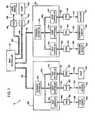
- FIG. 1illustrates a preferred embodiment of a medical perfusion system 10 in accordance with the invention.
- the perfusion system 10is adapted to handle the selective oxygenation, filtering and recirculation of blood in connection with a number of different medical procedures.
- the perfusion system 10may be placed in a number of different configurations, each of which corresponds to a different medical procedure.
- the perfusion system 10may be configured as a full-function heart/lung machine, a ventricular assist system, or a single-pump system that can be used for various purposes, such as to perform blood aspiration or myocardial protection during surgery.
- the main controller 20is connected to a network extender 22a via a data/power bus 30a and to a network extender 22b via a data/power bus 30b.
- the network extender 22aincludes an extender controller 32a connected to three node controllers 34a, 34b, 34c via a data/power bus 30c.
- the node controller 34ais connected via a data/power bus 30d to an adapter pod 40a, which is in turn connected to a perfusion device 50 in the form of a flow sensor 50a via a bidirectional data/power line 52a.
- the node controller 34bis connected via a data/power bus 30e to an adapter pod 40b, which is connected to an air embolus sensor 50b via a bidirectional line 52b.
- the node controller 34cis connected via a data/power bus 30f to an adapter pod 40c, which is connected to a blood pump 50c via a bidirectional line 52c.
- the network extender 22bincludes an extender controller 32b connected to three node controllers 34d, 34e, 34f via a data/power bus 30g.
- the node controller 34dis connected via a data/power bus 30h to an adapter pod 40d, which is connected to a pressure sensor 50d via a bidirectional line 52d.
- the node controller 34eis connected via a data/power bus 30i to an adapter pod 40e, which is connected to a temperature sensor 50e via a bidirectional line 52e.
- the node controller 34fis connected via a data/power bus 30j to an adapter pod 40f, which is connected to a flow occluder 50f via a bidirectional line 52f.
- the main controller 20is operatively coupled to a blood pump 50g via a bidirectional line 52g connected to an adapter pod 40g.
- the pod 40gis connected to the main controller 20 via a data/power bus 30k.
- the main controller 20is operatively coupled to a level sensor 50h via a bidirectional line 52h connected to an adapter pod 40h, which is connected to the main controller 20 via a data/power bus 301.
- perfusion deviceis a device designed to be used in a medical perfusion system, including but not limited to a blood pump such as a centrifugal or roller pump, a flow sensor, a pressure sensor, a temperature sensor, a level sensor, an air embolus sensor or an occluder.
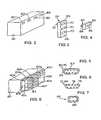
- FIG. 2is a perspective view of a portion of one mechanical embodiment of the main controller 20.
- the main controller 20has four network connectors 60, which are shown schematically.
- Each of the network connectors 60is identical and has the same connector configuration.
- FIG. 5illustrates the structure of the connectors 60.
- each connector 60may be, for example, a standard personal computer connector having nine conductive pins 62 partially surrounded by an asymmetrical metal housing 64.
- FIG. 3is a perspective view of one embodiment of the network extenders 22 shown schematically in FIG. 1 .
- Each network extender 22has a hexahedral housing 66 with one side 68 on which three connectors 70 are disposed and an opposite side on which a connector 72 is disposed.
- Each connector 70is identical to the connectors 60 and has the structure shown in FIG. 5 .
- the connector 72which is shown in FIG. 6 , has nine pin receptacles 74 formed in an asymmetrical housing 76 composed of an insulating material such as plastic. The pin receptacles 74 are located to correspond to the positions of the nine pins 62 of the connector 60. Consequently, the connector 72 has the same connector configuration as the connector 60 and thus can be plugged into the connector 60.
- FIG. 4is a perspective view of the adapter pods 40 shown schematically in FIG. 1 .
- each adapter pod 40has a hexahedral housing with one side 82 on which a connector 84 is disposed and an opposite side on which a connector 86 is disposed.
- the connector 86is identical to the connectors 72 described above (and shown in FIG. 6 ).
- the connector 84is adapted to be connected to a device connector (not shown) that is associated with one of the perfusion devices 50 described above.
- the connector 84has a different connector configuration than the connectors 60, 70, 72, 86.
- One example of the structure of the connector 84is shown in FIG. 7 to include six conductive pins 88.
- each of the adapter pods 40is adapted to be connected to a different type of perfusion device 50 (the pumps 50c, 50g may be different types of pumps, such as a roller pump or a centrifugal pump), the connector 84 disposed on each of the adapter pods 40 may have a different connector configuration.
- any of the adapter pods 40may be plugged into any of the connectors 60, 70.
- any combination of perfusion devices 50may be connected to the main controller 20.
- FIG. 8illustrates the main controller 20 having the network extenders 22 and the adapter pods 40 connected to it.
- Each of the adapter pods 40 of FIG. 8would be connected to a respective one of the perfusion devices 50 shown in FIG. 1 via a respective connector (not shown) attached to the perfusion device 50 by a cable.
- network extenders 22Although the form of the network extenders 22 shown in FIGS. 3 and 8 makes the resulting control unit compact, network extenders having different structures could be used. For example, instead of having the connector 72 fixed on the housing 66, the connector 72 could be connected to the housing 66 via a cable. Alternatively, the housing 66 could be eliminated, and the connectors 70, 72 could be interconnected via cables.
- FIG. 9is a block diagram of the main controller 20 shown schematically in FIG. 1 .
- the main controller 20has a microprocessor (MP) 100, a random-access memory (RAM) 102, a nonvolatile memory 104 such as a hard disk or a flash RAM, a network controller 106, a drawin controller 108, and an input/output (I/O) circuit 110, all of which are interconnected by an address/data bus 112.
- the I/O circuit 110is connected to a display device 114, such as a CRT or a flat-panel display, and an input device 116, such as a keyboard or electronic mouse or a touch screen on the display device 114.
- the main controller 20also includes a power supply circuit 118 that is connected to an outside source of AC power and which includes an internal transformer (not shown) that generates +5 volt and +24 volt DC power on a pair of electrical power lines relative to a ground line, which lines are schematically designated 120 in FIG. 9 .
- the electrical power and ground lines 120are provided to each of four node controllers 34g-34j via a data/power bus 30m and to the other node controllers 34 via the other portions of the network bus 30.
- the data/power bus 30mincludes a number of data communication lines which are connected to the network controller 106.
- FIG. 10is a block diagram of the extender controller 32a shown schematically in FIG. 1 (the design of the extender controllers 32a, 32b is the same).
- the extender controller 32ahas a controller 130 and a switch 132, both of which are connected to the data/power bus 30a.
- the extender controller 32ais connected to its parent node controller 34g via a bidirectional signal line 133.
- a "parent" deviceis a connected device that is closer to the network controller 106 ( FIG. 9 ) of the main controller 20.
- the node controller 34gtransmits a unique physical address to the extender controller 32a via the line 133, and the extender controller 32a includes a driver circuit 135 which is used to periodically transmit a check-in code to the node controller 34g via the line 133.
- the check-in code and the physical addressmay be the same binary code.
- FIG. 11illustrates a block diagram of the node controller 34a shown schematically in FIG. 1 (the design of all the node controllers 34 is the same).
- the node controller 34ahas a controller 140 which receives an enable signal or a disable signal from the extender controller 32a via one of the lines 134 and a periodic check-in code from the adapter pod 40a via the line 133.
- the controller 140is connected to a code generator 144 via a multi-signal line 146.
- the code generator 144generates a predetermined multi-bit binary code that uniquely specifies the physical address of the node controller 34a.
- the code generator 144may be, for example, a number of printed metal circuit lines, one line for each bit of the code, each line being selectively connected either to +5 volts (logic "1") or to ground (logic "0").
- the controller 140selectively operates a switch 150 that either connects or disconnects a data bus 152, which may be composed of two individual data lines, that is part of the data/power buses 30c, 30d (and the other buses 30 that make up the network).
- a switch 150When the switch 150 is open, the data buses 30c, 30d are disconnected, and when the switch 150 is closed, the buses 30c, 30d are connected to enable data communications between the adapter pod 40a and the other devices connected to the network 30.
- the controller 140also operates a switch 154 that controls whether +24 volt DC power (relative to a ground line 120c) on a electrical power line 120a is supplied to the adapter pod 40a and a switch 158 that controls whether +5 volt DC power on an electrical power line 120b is supplied to the adapter pod 40a.
- the electrical power lines 120a, 120bare part of the data/power buses 30c, 30d and the other buses 30 that make up the network.
- a resistor 162is connected in parallel with the switch 154, and a resistor 164 is connected in parallel with the switch 158.
- the resistors 162, 164act as current-limiting resistors which prevent large amounts of current from being drawn from the power lines 120a, 120b when the switches 154, 158 are open.
- the controller 140is connected to a driver circuit 170 which is used to transmit the physical address generated by the code generator 144 to the adapter pod 40a via the line 133.
- FIG. 12illustrates a block diagram of the adapter pod 40a shown schematically in FIG. 1 .
- the adapter pod 40ahas a controller 180 which is powered by a power supply 182 connected to the electrical power lines 120a, 120b.
- the controller 180may transmit a check-in code on the line 133 via a driver 184.
- the controller 180receives network messages from the data bus 152 and transmits messages onto the data bus 152 via a transceiver 186.
- the controller 180is connected to a memory 188 and to a device interface circuit 190.
- the device interface circuit 190has a plurality of data lines 192 and a plurality of electrical power lines 194 which are connected to the perfusion device 50a via the connector 84 ( FIG. 7 ).
- the controller 180causes various types of data signals to be transmitted to the perfusion device 50a via the data lines 192.
- the signals on the data lines 192might include, for example, digital or analog signals (e.g. 4-20 ma signals) relating to the control of the perfusion device 50, such as a desired pump speed or mode of operation.
- digital or analog signalse.g. 4-20 ma signals
- the number of data lines 192 useddepends on the particular perfusion device 50 to which the adapter pod 40 is connected.
- the controller 180also causes various types of electrical power to be transmitted to the perfusion device 50 via the power lines 194. These types of power include, for example, +5 volt DC power or +24 volt DC power. If power of another voltage level is necessary, the power supply circuit 182 may comprise a DC/DC converter.
- the operatorPrior to using the perfusion system 10 for a medical procedure, the operator connects the desired perfusion devices 50 to the main controller 20 by physically connecting the desired adapter pods 40 and/or network extenders 22 to the main controller 20, as shown in FIG. 8 .
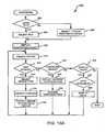
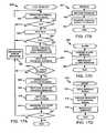
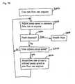
- FIG. 13Ais a flowchart of a configuration computer program routine 200 executed by the main controller 20.
- the programgenerates a visual prompt to the operator to request whether a previous configuration file should be loaded from the memory 104 of the main controller 20.
- a configuration filegenerally includes image data corresponding to an image of a perfusion circuit, which may include an outline of the patient, images of a plurality of fluid conduits connected to the patient, and images of the various perfusion devices 50 used in the system 10.
- Each perfusion device 50may be represented by a different image, depending upon the type of perfusion device. For example, pumps may be represented by a pump image, whereas a flow sensor may have a different image.
- the configuration filemay also include data relating to the perfusion devices 50, such as the manufacturer and model number of the device, the desired operational mode of the device, numeric limits at which an alarm should be triggered, and identification of any associated perfusion device.
- Two perfusion devicesmay be "associated" if one device that is used to control a physical process, referred to herein as a control device, is to receive feedback from another perfusion device, referred to herein as a sensing device.
- the pump 50gcould be controlled based on feedback generated by either the level sensor 50h (which would generate a signal indicative of fluid level within a fluid reservoir) or the flow sensor 50a.
- the pump 50gcould be controlled to maintain a predetermined level of fluid within the reservoir, and in the latter case the pump 50g could be controlled to maintain a predetermined flow through the conduit.
- Any type of conventional feedback controlcould be used, such as proportional-integral (PI) or proportional-integral-derivative (PID) control.
- PIproportional-integral
- PIDproportional-integral-derivative
- step 204the operator is prompted to select one of those configuration files. If the operator did not want to retrieve a previously stored configuration file, the program branches to step 206, where the operator selects one of a predetermined number of types of perfusion circuit images. Each perfusion circuit image could correspond to the perfusion circuit that would be utilized for a different medical procedure. Two different types of perfusion circuit images are illustrated in FIGS. 14A, 14B described below.
- either the perfusion circuit image corresponding to the configuration file selected at step 204 or the perfusion circuit image selected at step 206is displayed on the display 114.
- a pair of exemplary perfusion circuit images that may be displayed on the display 114are illustrated in FIGS. 14A and 14B .
- the perfusion circuit image 232includes a patient image 234, an image 236 of a fluid conduit which removes blood from the left ventricle of the patient, an image 238 of a pump, an image 240 of a fluid conduit which returns blood to the aorta of the patient, an image 242 of a flow occluder, an image 244 of a temperature sensor, and a pair of images 246 of an air embolus sensor.
- LVADleft ventricle assist device
- FIG. 14Ban image 248 of a perfusion circuit corresponding to a bi-ventricular assist device (Bi-VAD) configuration is shown.
- the perfusion circuit image 248includes all of the images shown in FIG. 14A , as well as an image 250 of a second blood pump, an image 252 of a conduit which removes blood from right ventricle of the patient, and an image 254 of a conduit that returns blood to the pulmonary artery of the patient.
- Each of the perfusion circuit images illustrated in FIGS. 14A, 14Bcould be pre-stored in the memory 104 of the main controller 20, in addition to other types of perfusion circuit images.
- the operatormay select one of a number of configuration options to change the configuration of the perfusion system 10. If the operator selects the option of adding a perfusion device 50 as determined at step 212, the program branches to step 214 where the operator is prompted to select a type of perfusion device 50, such as a pump or a flow sensor, to add to the perfusion circuit image displayed on the display 114.
- the operatorselects the position at which an image of the newly selected perfusion device 50 will be displayed. This position could be specified by the operator via an electronic mouse, and the displayed perfusion circuit image could include a number of possible connection points 256 ( FIG. 14A ) at which the perfusion device 50 could be connected.
- connection points 256could be highlighted, such as by placing them in a bold color or making them blink on and off, so that the possible connection points 256 are readily apparent to the operator.
- an image of the perfusion deviceis displayed in the perfusion circuit image at that position.
- the programbranches to step 222 where the current configuration of the perfusion device 50 is displayed next to the image of the device in the perfusion circuit.
- the current configurationcould include the mode of operation of the perfusion device, alarm limits for the device, any associated perfusion devices, etc.
- the operatormay change or add to the current configuration.
- step 226the program branches to step 228 where it checks to determine whether there is data available to display. Such data could include, for example, the manufacturers and model numbers of the perfusion devices. If there is data available as determined at step 228, the program branches to step 230 where the data is displayed next to the perfusion devices in the perfusion circuit.
- the main controller 20may utilize a plug-in procedure to accommodate perfusion devices 50 that are subsequently connected to the perfusion system 10.
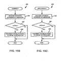
- FIG. 13Bis a flowchart of a plug-in routine 260 performed by the main controller 20.
- the main controller 20may operate in an automatic match mode in which it can match a previously entered device configuration with a perfusion device that is subsequently connected to the main controller 20.
- a operatormay configure a centrifugal blood pump (not yet connected to the main controller 20) to operate in a continuous mode to continuously pump a predetermined flow.
- the controller 20will then automatically match the previously stored pump configuration with the pump.
- step 262if the main controller 20 is in the automatic match mode, the program branches to step 264 where it determines whether there is only one possible match between the perfusion device just connected and the previously stored device configurations. This would be the case where there is only one previously stored configuration for a pump and where the device that was just connected to the main controller 20 was a pump.
- step 266determines whether the position at which the device is to be displayed in the perfusion circuit image is known. This position could be included in the previously stored configuration for the device. If the position is not known, the program branches to step 268 where the operator is prompted to select a position, and then the program branches to step 270 where an image of the newly connected perfusion device is displayed in the perfusion circuit image. If the position of the device as determined at step 266 was known, the program skips step 268 and branches directly to step 270.
- step 272If the main controller 20 was not in the automatic match mode, as determined at step 262, or if there was more than one possible match, as determined at step 264, the program branches to step 272. If the newly connected device has already been configured, the program branches to step 274 where the operator is prompted to select the proper configuration from a plurality of prestored configurations. If the device is not already configured, the program branches to step 276 where the operator enters the desired configuration parameters for the device. The program then performs steps 268 and 270 described above.
- the network controller 106( FIG. 2 ) in the main controller 20, which may be a conventional network controller such as a CAN Version 2.0B, oversees the data flow on the network buses 30, each of which includes the data bus 152 (which may be composed of two wires) on which digital data packets are transmitted and received.
- the data packetsmay have a conventional format composed of the following data fields: 1) a start-of-frame (SOF) field; 2) an arbitration field; 3) a control field; 4) a variable-length data field; 5) an error detection/correction field, such as a cyclic-redundancy-check (CRC) field; 6) an acknowledgement (ACK) field; and 7) an end-of-frame (EOF) field.
- SOFstart-of-frame
- CRCcyclic-redundancy-check
- ACKacknowledgement
- EEFend-of-frame
- the arbitration fieldwhich may be a 29-bit field, is used to determine the priority of the data packets broadcast over the network bus 30. The priority is based on the overall numeric value of the arbitration field of the data packets. In the event of a conflict in the transmission of two data packets, the data packet having the arbitration field with a lower numeric value takes priority.
- the arbitration fieldswhich contain a message identification (ID) code specifying the type of message, of a number of different data packet types that may be used are listed below.
- the type A messagecorresponds to a control message broadcast by the main controller 20 to all devices attached to the network data buses.
- the data fields "ccccccccccccccccccccccccccccccc"are used to specify the type of message.
- the type B messagecorresponds to a message broadcast by the main controller 20 to the extender controllers 32.
- the data fields "ccccccccccccccccccccccccccccccc"are used to specify the type of message.
- the type C messagecorresponds to an alarm or safety message, with the data field "aaaaaaaa” specifying an alarm type and the data field "sssssss” specifying the logical address of the device which generated the alarm message.
- the type D messagecorresponds to a servo message generated by a sensing device, such as a flow sensor.
- the data field "ccccccccccc”specifies the type of sensed parameter, e.g. flow, and the data field "sssssss" specifies the logical address of the sensor that generated the sensed parameter.
- the type E messagecorresponds to a general message having a data field "cccccccccccccccccccccc" which specifies the type of message and a data field "ddddddd” which specifies the logical address of the intended destination of the message.
- the type F messagecorresponds to a general message having a data field "cccccccccccccccccccc" which specifies the type of message and a data field "sssssss" which specifies the logical address of the source of the message.
- the type G messagecorresponds to a general message having a data field "cccccccccc" which specifies the type of message and a data field "dddddddddddddddddd” which specifies the physical address of the intended destination of the message.
- the type H messagecorresponds to a general message having a data field "cccccccccc" which specifies the type of message and a data field "sssssss ssssssss” which specifies the physical address of the source of the message.
- the type I message(which is all logical "1"s) corresponds to a status request from the main controller 20 that is periodically broadcast to all devices connected to the network data buses.
- the status request message from the main controller 20would not have a data field.
- Other messageswould include data fields.
- the servo message(type D above) would include a data field which specified the numeric value of the sensed condition, such as a flow reading of 0.257 liters per minute.
- the main controller 20, the extender controllers 32, and the adapter pods 40may include conventional electronics for checking the accuracy of received messages via the CRC field, requesting retransmission of messages that were not accurately received, and for transmitting acknowledgement messages in response to the receipt of accurately received messages.
- the messages described abovemay be transmitted or broadcast to all the devices connected to the network 30.
- Each devicesuch as a pod 40 or an extender controller 32, can discriminate by receiving only certain messages that are broadcast. For example, this discrimination could be accomplished by accessing a message-discrimination memory in the receiving device which stores the logical addresses of all the other devices in which the receiving device is interested.
- the message-discrimination memory of the pod 40cwould include the logical address of the flow sensor 50a, so that the pod 40c would receive any message generated by the pod 40a connected to the flow sensor 50a.
- the message-discrimination memorywould include logical address of the main controller 20, and could include the logical addresses of a number of other pods 40. Consequently, it should be noted that it is not necessary that messages broadcast over the network 30 include a specific destination address (although a destination address may be included).
- the pods 40 and extender controllers 32could also discriminate messages based on the type of message instead of the identity of the sender. For example, a pod 40 could receive all status-request messages and configuration messages (described below). The message identification codes for such messages could also be stored in the message-discrimination memory.
- the configuration messagesinclude all the necessary configuration data described above.
- the configuration datawould include the operational mode of the pump, the desired flow rate of the pump, etc. If any configuration messages which include device association data (e.g. the sensor which a blood pump should receive feedback from) were received by a pod 40, the message-discrimination memory would be updated with the logical address of the associated device.
- the adapter pods 40In order for them to communicate with the main controller 20 via the network data/power buses 30, the adapter pods 40 must be granted permission to connect to the network 30. This connection is initiated with a startup-request message transmitted to the main controller 20 by the adapter pod 40 for which the network connection is to be made.
- the startup-request messageincludes a first code identifying the type of perfusion device 50 connected to the pod 40 requesting to be connected and a second code identifying the physical address (specified by the code generator 144 of FIG. 11 ) of the pod 40 requesting to be connected.
- FIG. 13Cis a flowchart of a startup routine 280 that is performed by the main controller 20 in response to the receipt of a startup-request message from an adapter pod 40.
- the startup routine 280may be an interrupt service routine which is invoked in response to an interrupt generated upon the receipt of a startup-request message by the main controller 20.
- the startup message received by the main controller 20is decoded to determine the type of the perfusion device 50 attached to the pod 40 requesting to be connected and to determine the physical address of the pod 40.
- the programdetermines whether full power should be granted to the requesting pod 40.
- electrical power to run the perfusion devices 50is provided to the pods 40 via the network 30 from a power supply 118 ( FIG. 9 ) in the main controller 20. Since the power available from the power supply 118 may be limited, the main controller 20 may be programmed to allow only a certain number of perfusion devices 50 to be connected to the network 30, or alternatively, to allow only certain numbers of specific types of perfusion devices 50 to be connected. For example, since control devices such blood pumps typically draw more power than sensing devices, the main controller 20 may be provided with an upper limit on the number of control devices that can be connected to the network 30.
- the decision whether to grant full powercould be made by comparing the number of perfusion devices 50 already connected to the network 30 with the maximum number that can be connected to determine whether the connection of an additional device 50 will cause the maximum to be exceeded. Alternatively, if the device requesting connection is a control device, then the number of control devices already connected could be compared with the maximum number of control-type perfusion devices that can be connected. If it is determined that full power should not be granted, the program simply ends.
- steps 286-298are performed to generate and transmit a startup granted message that will cause the pod 40 associated with the perfusion device 50 to be connected to the network 30.
- a unique logical addressis allocated to the newly connected pod 40.
- the logical addressmay be a four-bit binary code.
- a startup-granted message which includes the logical addressis encoded, and at step 290 the startup-granted message is transmitted over the network 30.
- the pod 40 which requested startupis local to the main controller 20 (i.e.
- full power to the pod 40is enabled via the local node controller (i.e. one of the node controllers 34i-34j of FIG. 9 ) connected to the perfusion device 50. Referring to FIG. 11 , this is accomplished by sending an enable signal on the line 134, which will cause the controller 140 to close the switches 150, 154, 158 so that full power is supplied on the power lines 120a, 120b and so that the adapter pod 40 is connected to the data bus 152.
- the local node controlleri.e. one of the node controllers 34i-34j of FIG. 9
- step 296a connect message which includes the physical address of the node controller 34 associated with the pod 40 requesting startup is encoded, and then to step 298 where the connect message is transmitted over the network 30.
- the extender controllers 32receive the connect message, they decode it to determine the physical address, and the extender controller 32 connected to the node controller 34 having that physical address (i.e. the node controller 34 associated with the requesting pod 40) turns on full power by transmitting an enable signal on the line 134 connected to that node controller.
- the main controller 20periodically transmits a status-request message to all extender controllers 32 and adapter pods 40 on the network 30.
- Each extender controller 32 and adapter pod 40must respond to the status request within a predetermined period of time. Any extender controller 32 or pod 40 that fails to respond to the status request within that time period is disconnected from the network 30, and a corresponding alarm message is generated on the visual display 114 to warn the operator of such event.
- FIG. 13Dis a flowchart of a status-request routine 300 periodically performed by the main controller 20.
- a status-request messageis encoded, and at step 304 the message is broadcast to all extender controllers 32 and adapter pods 40 connected to the network 30.
- the status-request messagemay simply be all logical "1"s in the arbitration of the data packet.
- a predetermined time-out period within which all extender controllers 32 and pods 40 must respond to the status request messageis started.
- each extender controller 32 and adapter pod 40Upon receiving the status-request message, each extender controller 32 and adapter pod 40 encodes a status message with its logical address and its status, and then broadcasts the status message to the main controller 20 over the network 30.
- FIG. 13Eis a flowchart of a receive status routine 310 that is performed by the main controller 20 upon receipt of a status message transmitted to it in response to the status-request message previously transmitted by the routine 300.
- the logical address of the responding extender controller 32 or adapter pod 40is determined from the status message
- the status of the device 32 or 40is determined from the message. The status may be specified by a number of different binary status codes.
- the programsimply ends. However, if the status is not okay, the program branches to step 318 where it responds to a status condition identified by the status code. If the condition is relatively minor, the main controller 20 may simply generate a warning on the visual display 114 of the perfusion system 10. If the condition is serious enough, the main controller 20 may disconnect the device 32 or 40 from the network 30.
- FIG. 13Fis a flowchart of a disconnect routine 330 that causes an extender controller 32 or an adapter pod 40 to be disconnected from the network 30.
- the disconnect routine 330is performed by the main controller 20 in response to either: 1) the failure of a device 32 or 40 to transmit a status message to the main controller 20 within the timeout period described above or 2) a serious malfunction of a device 32 or 40 as determined at step 318 of FIG. 13E .
- step 332if the device 32 or 40 to be disconnected is local to the main controller 20, the program branches to step 334 where that device 32 or 40 is disconnected by the node controller 34g, 34h, 34i, or 34j in the main controller 20 that is connected to that device 32 or 40.
- the disconnectionis accomplished by transmitting a disable signal on the line 134, which will cause the controller 140 to open the switches 150, 154, 158 so that the data bus 152 and the power lines 120a, 120b are disconnected.
- step 332if the device to be disconnected is not local to the main controller 20, the program branches to step 336 where a disconnect message which includes the physical address of the node controller 34 of the device 32 or 40 to be disconnected is encoded, and then to step 338 where the disconnect message is transmitted over the network 30.
- the device to be disconnectedis a pod 40 connected to an extender controller 32 via a node controller 34
- that extender controller 32receives the disconnect message, it decodes it to determine the physical address of the pod 40 to be disconnected, and the node controller 34 associated with that pod 40 disconnects the pod 40 by transmitting a disable signal on the line 134 connected to that node controller 34.
- FIG. 13Gis a flowchart of a control command routine 350 which illustrates how the main controller 20 responds to those inputs. While FIG. 13G discloses various possible operator inputs, it should be understood that the main controller 20 could respond to other or additional operator inputs.
- step 352if the input entered by the operator was a control command, the program branches to step 354 where a control message corresponding to the control command is encoded in a data packet, and then to step 356 where the control message is broadcast over the network 30.
- the control messagecould be one of the following: 1) a new alarm limit for a particular sensing device; 2) a new mode of operation for a blood pump; 3) a new target flow value for a blood pump; 4) a new rate at which a particular sensing device should be read; 5) a pump start command; 6) a pump stop command; etc.
- step 358if the operator requests that a particular alarm be reset, the program branches to step 360 where a corresponding alarm-reset message, which includes the logical address of the device that generated the alarm, is encoded and to step 362 where the alarm-reset message is broadcast over the network 30.
- step 364if the operator requests that the perfusion system 10 be reset, the program branches to step 366 where a corresponding system reset message is encoded and to step 362 where the system reset message is broadcast over the network 30.
- FIG. 13His a flowchart of a receive routine 370 performed by the main controller 20 that illustrates actions taken by the main controller 20 in response to the receipt of various types of messages.
- step 372if the received message corresponds to an event message, such as an alarm or other event, the program branches to step 374 where the visual display generated on the display device 114 is updated to advise the operator of that event, and the program branches to step 376 where the event is logged into an event log stored in the memory 104 of the main controller 20.
- an event messagesuch as an alarm or other event
- step 378if the received message corresponds to a data message, such as a message which includes the numeric value representing the output of a flow sensor, the program branches to step 380 where the visual display is updated, and the program branches to step 382 where the data and the device which generated the data are logged into a data log stored in the memory 104 of the main controller 20.
- a data messagesuch as a message which includes the numeric value representing the output of a flow sensor
- step 384if the received message is a status message, the program branches to step 386 where the status message is processed, as described above in connection with FIG. 13E .
- step 388the visual display is updated based on the status, and at step 390 the status is stored in a status log stored in memory.
- step 392if the received message is a startup request, the program branches to step 394 where the startup request is processed, as described above in connection with FIG. 13C , and at step 396, the visual display is updated.
- FIG. 15Ais a flowchart of a startup routine 420 performed by the controller 130 of each extender controller 32.
- the extender controller 32performs a number of internal self-tests, such as tests of an internal RAM and an internal ROM.
- the programbranches to step 426 where the connection of the extender controller 32 to the network bus 30 is tested by transmitting a message onto the network bus 30 and simultaneously receiving the message from the network bus 30 as it is transmitted to determine if the message was in fact transmitted.
- step 428if the data bus test was successful, the program branches to step 430 where the extender controller 32 starts to periodically transmit a check-in code to its parent node controller 34 via the line 133.
- the extender controller 32starts to periodically transmit a check-in code to its parent node controller 34 via the line 133.
- each deviceeither an adapter pod 40 or an extender controller 32
- the extender controller 32waits for its physical address to be transmitted to it from its parent node controller 34.
- an error messageis broadcast over the network 30:
- the error messageincludes the physical address of the extender controller 32 and a binary code which specifies which test(s) were not passed.
- step 438a startup-request message containing the physical address of the extender controller 32 is encoded and broadcast over the network 30.
- step 440the program waits until a startup-granted message is received from the main controller 20, and then at step 442 the program waits until full power is granted to the extender controller 32 via the electrical power lines 120a, 120b of its parent node controller 34.
- step 444the extender controller 32 measures the voltages on and the current provided by the electrical power lines 120a, 120b to make sure they are within specification.
- step 446if the power measurements are not within specification, the program branches to step 436 where a message to that effect is broadcast to the main controller 20 over the network 30.
- FIG. 15Bis a flowchart of a connect routine 450 performed by an extender controller 32 when it receives a connect message from the main controller 20.
- the connect message received from the main controller 20is decoded to determine the physical address of the adapter pod 40 to be connected to the network 30.
- the physical addressis inspected to determine if the adapter pod 40 to be connected is local to the extender controller 32, meaning that the adapter pod 40 is one of the three that are connected to the extender controller 32. If the pod 40 is not local to the extender controller 32, no further action is taken and the routine 450 ends.
- step 456an enable signal is transmitted via one of the lines 134 to the node controller 34 associated with the adapter pod 40 to be connected, which causes the adapter pod 40 to be connected to the network 30 in the manner described above.
- a disconnect routine 460 shown in FIG. 15Cis performed by the extender controller 32.
- the disconnect message received from the main controller 20is decoded to determine the physical address of the adapter pod 40 to be disconnected to the network 30.
- the physical addressis inspected to determine if the adapter pod 40 to be disconnected is local to the extender controller 32. If the pod 40 is not local, no further action is taken. If the pod 40 is local, the program branches to step 466 where a disable signal is transmitted via one of the lines 134 to the node controller 34 associated with the adapter pod 40 to be disconnected, which causes the adapter pod 40 to be disconnected to the network 30.
- the basic function of the node controllers 34is to connect and disconnect the adapter pods 40 (if a node controller 34 is the parent of an adapter pod 40) and the extender controllers 32 (if a node controller 34 is the parent of an extender controller 32) from the network 30.
- the connection or disconnectionis performed pursuant to an enable or disable signal received either from the main controller 20 or from the extender controller 32 associated with the node controller 34, as described above.
- each node controller 34requires its associated device 32 or 40 to periodically check-in. If the device 32 or 40 fails to check in with a proper check-in code, the node controller 34 disconnects the device 32 or 40 from the network 30.
- FIG. 16Ais a flowchart of a node routine 470 performed by each of the node controllers 34.
- the routine 470is performed upon the receipt by the node controller 34 of a check-in code received from the associated device 32 or 40.
- a check-in codemay be the physical address specified by the code generator 144 ( FIG. 11 ) of the node controller 34.
- the node controller 34may compare the received code to determine whether it matches a predetermined code.
- step 474the program branches to step 474 where a time-out timer is restarted.
- the time-out timertracks the predetermined period of time within which the device 32 or 40 must transmit a valid check-in code.
- the node controller 34transmits the physical address generated by the code generator 144 to the pod 40.
- the node controller 34connects the device 32 or 40 to the data bus 152 ( FIG. 11 ) by sending a signal to the switch 150 which causes it to close (or remain closed if it was already closed).
- the node controller 34supplies full power to the device 32 or 40 by sending signals to the switches 154, 158 ( FIG. 11 ) to cause them to close (or remain closed if they were already closed).
- step 480the program branches to step 484, where the device 32 or 40 is disconnected from the data bus 152 by opening the switch 150 and to step 484 where the device 32 or 40 is disconnected from the electrical power lines 120a, 120b by opening the switches 154, 158.
- a time-out routine 490 shown in FIG. 16Bis performed by the node controller 34. Referring to FIG. 16B , at step 492 the device 32 or 40 is disconnected from the data bus 152 by opening the switch 150, and at step 494 the device 32 or 40 is disconnected from the electrical power lines 120a, 120b by opening the switches 154, 158.
- the adapter pods 40perform a number of functions, including receiving configuration and control messages transmitted by the main controller 20, receiving sensing messages containing numeric values of sensed conditions, such as flow, and/or transmitting sensing messages over the network 30. These functions are described below.
- FIG. 17Ais a flowchart of a startup routine 520 performed by the controller 180 of each adapter pod 40.
- the adapter pod 40performs a number of internal self-tests, such as tests of an internal RAM and an internal ROM.
- the programbranches to step 526 where the connection of the pod 40 to the data bus 152 is tested by transmitting a message onto the data bus 152 and simultaneously receiving the message from the data bus 152 as it is transmitted to determine if the message was in fact transmitted.
- step 528if the data bus test was successful, the program branches to step 530 where the adapter pod 40 starts to periodically transmit a check-in code to its parent node controller 34 via the line 133.
- the pod 40waits for its physical address to be transmitted to it from its parent node controller 34.
- step 534if not all of the tests performed at steps 522 and 526 were passed, an error message is broadcast over the network 30.
- the error messageincludes the physical address of the pod 40 and a binary code which specifies which test(s) were not passed.
- step 538a startup-request message containing the physical address of the adapter pod 40 is encoded and broadcast over the network 30.
- step 540the program waits until a startup-granted message is received from the main controller 20, and then at step 542 the program waits until full power is granted to the adapter pod 40 via the electrical power lines 120a, 120b of its parent node controller 34.
- step 544the pod 40 measures the voltages on and the current provided by the electrical power lines 120a, 120b to make sure they are within specification.
- step 546if the power measurements are not within specification, the program branches to step 536 where a message to that effect is broadcast to the main controller 20 over the network 30.
- an adapter pod 40may receive control or configuration messages from the main controller 20 over the network.
- FIG. 17Bis a flowchart of a receive routine 550 that is performed when the adapter pod 40 receives a message. Referring to FIG. 17B , at step 552 the message is decoded to determine the control command embedded in the message, and at step 554, the pod 40 transmits a control signal (via one or more of the data lines 192 in FIG. 12 ) to the perfusion device 50 connected to it.
- an adapter pod 40may receive an alarm signal from the perfusion device 50 via one of the data lines 192.
- an alarm routine 560 shown in FIG. 17Cis performed by the pod 40.
- an alarm messageis encoded with the logical address of the perfusion device 50 that generated the alarm and the type of alarm, and at step 564 the alarm message is broadcast over the network 30 to the main controller 20.
- each adapter pod 40 connected to a perfusion device 50such as a flow sensor, which generates a sensing signal periodically reads the numeric value of the sensing signal via one of the lines 152.
- the time period between successive readings of the sensing signalmay be specified during the configuration process as described above.
- FIG. 17Dis a flowchart of a sensing routine 570 that is performed when it is time to read the value of the sensing signal. Referring to FIG. 17D , at step 572 the sensing signal is read via one of the data lines 152.
- the numeric value of the sensing signalis encoded in a message along with the logical address of the perfusion device 50 which generated the sensing signal.
- that messageis then broadcast over the network 30 to all devices connected to the network 30.
- each adapter pod 40 connected to the network 30may be provided with a message-discrimination circuit which is used to selectively receive messages from only a subset of the devices connected to the network 30.
- the sensing messageis broadcast at step 576, the only devices that receive it are the main controller 20 (which may receive all messages broadcast over the network 30) and the particular perfusion device 50 which is being controlled based on the value of the sensing signal encoded in the sensing message.
- adapter podsmay be provided with additional functionality not described above. Also, instead of having electrical power being distributed over the network from a single power source provided in the main controller 20, electrical power could be distributed from a plurality of power sources, for example, from one power source provided in each of the network extenders.
- the fluid pumps in the perfusion system 10can be controlled in a variety of modes.
- FIG. 18shows an exemplary physical configuration in which the pumps can be controlled in various modes.
- FIG. 18two pumps 1866, 1868 are connected to the perfusion system 10 via pods 1844, 1846.
- the pods 1844, 1846operate in the same fashion as, or in a fashion consistent with, the adapter pods 40 described above.
- the pods 1844, 1846are located within the corresponding pump, and each pump and associated pod are capable of running in a standalone condition.
- the pump and its associated podcan run in a standalone condition when, for example, they are disconnected from the perfusion system 10 or when the perfusion system 10 malfunctions.
- FIG. 18also shows pods 1840, 1842, 1848 and 1850, that respectively connect the flow sensor 1860, pressure sensor 1862, flow sensor 1868, and pressure sensor 1870 to the perfusion system 10.
- the pods 1840, 1842, 1848 and 1850operate in the same fashion as, or in a fashion consistent with, the adapter pods 40 described above.
- the flow sensor 1860 and the pressure sensor 1862are configured to monitor the output 1874 of the pump 1864, and the flow sensor 1868 and the pressure sensor 1870 are arranged to monitor the output 1876 of the pump 1866, in a fashion consistent with the various sensors 50 previously described.
- the sensor pickupscan be located at any appropriate location, for example at locations at or within the patient being treated with the perfusion system 10, and/or at locations between the pumps and the patient.
- a sensor pickupcan monitor a condition that a pump influences but is not wholly responsible for, and provide feedback for controlling the pump.
- the sensorcan be placed at a confluence of fluid lines or at a location in a patient, where the fluid pressure and/or flow at that location is a result of several factors (including for example other pumps and/or the patient's physiological behavior), and one of the factors is the pump receiving feedback from the sensor.
- additional pumps and/or additional sensors of various kinds to help monitor and control the pumpscan also be provided, in addition to those shown in FIG. 18 .
- various ones of the pods 40 and the devices 50 shown in FIG. 1can also be provided.
- the sensors and pumps and their podscan communicate and can be electronically configured, controlled or monitored by the main controller 20, using for example the network communications protocol and network messages described further above (e.g. , using appropriate ones of the A-I message types).
- the sensor podscan convey information to the pump pods using type C, type D, type E, or type F messages.
- the pumps 1864, 1866can each be any of a variety of different kinds of pumps, including a roller pump and a centrifugal pump. Pump speeds can be measured by measuring the speed of the pump head and/or the speed of the motor driving the pump head, using for example known tachometers and known sensors such as Hall Effect sensors.
- FIG. 19shows a process in accordance with an exemplary implementation of the Back Off Response Mode.
- a parameter of the pump's performancesuch as pressure or flow rate
- controlproceeds to step 1904, where a determination is made as to whether the measured parameter exceeds a critical level. If No, then control returns to step 1902. If Yes, then control proceeds to step 1906, where the speed setpoint of the pump is reduced to create a new pump speed setpoint. From step 1906, control proceeds to step 1908, where the user is alerted to the situation. From step 1908, control returns to step 1902.
- the pump 1864is linked to the flow sensor pod 1840 and the pressure sensor pod 1842.
- the sensor pods 1840, 1842monitor circuit parameters and alert and alarm if a particular measurement level is crossed.
- the pressure sensor pod 1842can be set to alarm when it detects a pressure above a critical level of 150 mm Hg.
- the flow sensor pod 1840can be set to alarm when it detects a flow rate above a critical level of 4 liters per minute.
- the pump 1864which can for example be a centrifugal pump or a roller pump, is automatically connected to the sensing pods 1840, 1842, so that it will receive an alarm from either of the sensing pods 1840, 1842.
- the pump pod 1844When the pump pod 1844 receives an excess pressure alarm from the pressure sensor pod 1842, or an excess flow rate alarm from the flow rate sensor pod 1840, in response the pump pod 1844 reduces or "backs off” the speed of the pump 1864 by a predetermined amount, for example 10 % .
- the pump pod 1844can continue to back off or reduce the speed of the pump 1864 in 10 % decrements.
- a predetermined time periodcan be used between successive reductions, for example to allow the pump time to respond to a command to reduce speed, before a subsequent command is issued.
- the time periodcan vary depending on the amount by which the measured parameter exceeds the critical level. For example, if the measured pressure greatly exceeds the critical level, then it may be advantageous to have a smaller time period to reduce the pressure more quickly, or to have a larger percentage decrement.
- the pump speedcan be reduced by a fixed amount of revolutions per minute.
- the pump speedcan be reduced to a predetermined level.
- the predetermined levelcan be a "coasting level", i.e. , a small rpm value that is sufficient to prevent backflow, while not causing significant forward movement of the fluid being pumped.
- one or more of the fluid pumpsis controlled in a Flow Servo Mode.
- FIG. 20shows an exemplary process of the Flow Servo Mode.
- a usersets a flow rate setpoint. The user can do this, for example, by adjusting the speed of one or more pumps until a desired flow rate is achieved, and then indicating to the perfusion system 10 (or to the pump directly) that the present flow rate is now a setpoint.
- the usercan enter a desired flow rate setpoint that is different from the current flow rate, and the system will adjust to achieve the desired flow rate.
- controlproceeds to step 2004, where the pump speed is adjusted to achieve or maintain the flow rate at the setpoint.
- controlproceeds to step 2006, where fault conditions are checked for. If a fault is detected, control proceeds from step 2006 to step 2008, where the fault is handled appropriately. For example, pressure or flow rate exceeding a critical level can shift the pump (or pump pod) from Flow Servo Mode to Back Off Response Mode. Other faults can trigger other responses, some of which may temporarily or indefinitely suspend the Flow Servo Mode.
- step 2006determines whether the user has adjusted the pump speed. If No, then control returns to step 2004. If Yes, then control proceeds from step 2010 to step 2012, where the flow rate at the user's selected pump speed is adopted as the new flow rate setpoint. From step 2012, control returns to step 2004.
- the pump 1864(which can be, for example, a centrifugal pump or a roller pump) and the associated pod 1844, utilize an intelligent control system to maintain the blood or fluid flow rate to fixed value or setpoint within a clinical fluid flow setup, for example an arterial or cardioplegia circuit.
- the pump softwarecontained for example in the pump pod 1844, uses feedback from an external flow sensor such as the flow sensor 1860 via the pod 1840, and automatically adjusts the pump speed to maintain the fluid flow rate at the setpoint.
- the flow rate sensor 1860, flow pod 1840, pump pod 1844 and the pump 1864work in conjunction to set up or form the automatic control system.
- the flow pod 1840samples the flow rate measured by the flow sensor 1860 at a high frequency, and filters the sampled data to remove noise.
- the filtered flow samplesare sent from the flow pod 1840 via appropriate portions or mechanisms of the system 10 to the pump pod 1844, in real time.
- the pump pod 1844uses the filtered flow samples to automatically adjust the speed of the pump 1864 to maintain the flow rate at the setpoint.
- the pump pod 1844uses a piecewise linear control system to calculate necessary adjustments to the pump speed to maintain the flow rate at the setpoint in real time. No user/operator intervention is required.
- the Flow Servo Modeis initiated when the pump 1864 is running.
- the pump speedis adjusted until the correct speed and flow rate have been reached.
- the usercan "lock in” the pump to the current configuration of speed and flow rate, so that the pump pod 1846 will then capture the current flow rate from the flow pod 1840 and use the captured flow rate as the flow rate setpoint.
- the usercan change the setpoint while remaining in the Flow Servo Mode, by changing the pump speed. This temporarily disables the Flow Servo Mode until the user finishes adjusting the speed, at which point the Flow Servo Mode is re-enabled.
- the Flow Servo Modeadopts the new flow rate resulting from the new pump speed, as the new setpoint.
- the user's manual adjustment of the pump speedcan be detected via software by the pump pod, and the manual adjustment of the pump speed can be made for example via a manual speed control that is part of the pump.
- the useris alerted when the control system is unable to maintain the flow at the setpoint.
- operating parameters of the pump 1864are bounded to prevent unforeseen and/or undesirable action by the pump 1864.
- the control software in the pump pod 1844can limit a maximum acceleration of the pump (i.e., limit a maximum rate of change of the pump speed), can limit maximum pump speed, and can check flow data integrity and discern anomalous flow data to discern invalid flow data from the flow sensor pod 1840.
- the control software in the pump pod 1844can exit the Flow Servo Mode and maintain the current speed of the pump 1864 while alerting the user to the condition.
- Additional safety conditionscan also be set up, to operate within or in harmony with the Flow Servo Mode.
- the pump pod 1844can move from the Flow Servo Mode into the Back Off Response Mode when either an excess pressure or an excess flow rate condition is detected.
- the modecan return from the Back Off Response Mode to the Flow Servo Mode, for example when the pressure or flow rate has stabilized at an acceptable level, with the backed-off flow rate becoming the new set point of the Flow Servo Mode.
- the usercan be alerted each time operation shifts from one Mode to another, and can also be alerted when a Mode is suspended.
- the flow pod 1840can also be arranged to take certain actions when it detects specific conditions, for example by sending an alert signal when a backflow condition or a low-flow condition is detected.
- the pump pod 1844can be configured to appropriately respond to such trigger messages, for example by stopping or pausing the pump 1864.
- one or more of the fluid pumpsis controlled in a Pressure Servo Mode.
- FIG. 21shows an exemplary process of the Pressure Servo Mode.
- the usersets the pressure setpoint.
- controlproceeds to step 2104, where pump speed is adjusted to maintain measured pressure at the setpoint.
- step 2106where fault conditions are checked for. If a fault is detected, control proceeds from step 2106 to step 2108, where the fault is handled appropriately. For example, pressure or flow exceeding a critical level can shift the pump from Pressure Servo Mode to Back Off Response Mode. Other faults can trigger other responses, some of which may temporarily or indefinitely suspend the Pressure Servo Mode.
- step 2106determines whether the user has adjusted the pump speed. If No, then control returns to step 2104. If Yes, then control proceeds from step 2110 to step 2112, where the pressure at the user's selected pump speed is adopted as the new pressure setpoint. From step 2112, control returns to step 2104.
- the pump 1864(which can be, for example, a centrifugal pump or a roller pump), and the associated pod 1844 utilize an intelligent control system to maintain the fluid pressure to the fixed value or setpoint within a clinical blood flow setup, i.e. , an arterial or cardioplegia circuit.
- the pump 1864 and pod 1844use feedback from the external pressure sensor 1862 via the pressure pod 1842, to automatically adjust the speed of the pump 1864 to maintain the fluid pressure at the setpoint.
- the pump 1864, pod 1844, pressure sensor 1862 and pressure pod 1842work in conjunction to set up the automatic control system of the Pressure Servo Mode.
- the pressure pod 1842samples the pressure signal from the pressure sensor 1862 at a high frequency, and filters the data to remove noise. In particular when the pump 1864 is a roller pump, this can be important as the mechanical operation of the roller pump introduces large pressure spikes into the pressure data. These spikes should be removed if the data are used as feedback signals to control the roller pump.
- the filtered pressure samplesare sent from the pressure pod 1842 via the perfusion system 10 to the pump pod 1844, in real time.
- the pump pod 1844uses the filtered pressure samples to automatically adjust the speed of the pump 1864 to maintain the pressure at the setpoint.
- the pump pod 1844also takes into account the size of the tube in the pump, so that the pump pod 1844 can correctly adjust the control parameters to provide proper pump response for different tubing setups.
- the pump pod 1844can be configured to work with a variety of different pumps having different configurations, including roller pumps having different tubing sizes, and knowledge of the tubing size in the particular roller pump the pod is connected to allows the pod to correctly control the pump.
- the control software in the pump pod 1844uses a piecewise linear control system to calculate adjustments to the pump speed to maintain the pressure at the setpoint in real time. No user intervention is required.
- the Pressure Servo Modeis initiated when the pump 1864 is running.
- the pump speedis adjusted until the correct speed and flow rate have been reached.
- the usercan "lock in” the pump to the current configuration of speed and flow rate, and the pump pod 1846 will then capture the current pressure from the pressure pod 1842 and use the captured pressure as the pressure setpoint.
- the usercan change the set point while remaining in the Pressure Servo Mode, by changing the pump speed. This temporarily disables the Pressure Servo Mode until the user finishes adjusting the speed, at which point the Pressure Servo Mode is re-enabled, with the new pressure resulting from the new pump speed, being adopted as the new setpoint.
- the user's manual adjustment of the pump speedcan be detected via software by the pump pod, and the manual adjustment of the pump speed can be made for example via a manual speed control that is part of the pump.
- the useris alerted when the control system is unable to maintain the pressure at the setpoint.
- operating parameters of the pump 1864are bounded to prevent unforeseen and/or undesirable action by the pump 1864.
- the control software in the pump pod 1844can limit a maximum acceleration of the pump (i.e., limit a maximum rate of change of the pump speed), can limit maximum pump speed, and can check pressure data integrity and discern anomalous pressure data to discern invalid pressure data from the pressure sensor pod 1842.
- the control software in the pump pod 1844can exit the Pressure Servo Mode and maintain the current speed of the pump 1864 while alerting the user to the condition.
- Additional safety conditionscan also be set up, to operate within or in harmony with the Pressure Servo Mode.
- the pump pod 1844can move from the Pressure Servo Mode into the Back Off Response Mode when either an excess pressure or an excess pressure condition is detected.
- the modecan return from the Back Off Response Mode to the Pressure Servo Mode, with the backed-off flow rate becoming the new set point of the Pressure Servo Mode.
- the usercan be alerted each time operation shifts from one Mode to another, and can also be alerted when a Mode is suspended.
- the pressure pod 1842can also be arranged or configured to take certain actions when it detects specific conditions, for example by sending an alert signal when an excessively low or high pressure is detected.
- the pump pod 1844can be configured to appropriately respond to such trigger messages, for example by stopping or pausing the pump 1864.
- two or more of the fluid pumpsare controlled in a Master-Slave Servo Mode.
- one or more pumpsis slaved to the behavior of another pump.
- the pumpscan, for example, be centrifugal or roller pumps.
- the pumps 1864, 1866are both roller pumps, and are applied to mix a drug with a patient's blood in order to deliver the drug to the patient.
- the pump 1864is the master pump
- the pump 1866is slave pump.
- the master pumpsends its pump speed to the slave pump, and the slave pump uses the pump speed from the master pump as a control signal to maintain a slave pump speed that is a fixed percentage of the master pump speed.
- the percentagecan be a fraction that is less than one, or a fraction that is greater than one.
- the master pumpresponds to all trigger conditions, and can also operate in the Flow Servo Mode or the Pressure Servo Mode.
- the slave pumpWhen the slave pump is in the Master-Slave Servo Mode, it emulates the master pump's behavior at the fixed percentage or ratio, regardless of which mode the master pump is in. In an exemplary embodiment of the invention, If the slave pump cannot maintain or achieve the pump speed at the required level, for example if the slave pump cannot keep up with the master pump, then the slave pump alerts the user of this condition.
- each pumpis equipped with a small display screen and an internal pod, and can display a flow rate and/or cumulative volume of fluid passing through the pump.
- the master pumpcan also be configured by the main controller 20 to display a combined flow and/or cumulative volume of the slave and master pumps.
- software in the pump podcan determine these values based on a known tubing size or capacity of the pump(s), the speed(s) of the pump(s), and elapsed time.
- the podcan receive the tubing size or capacity information from the main controller 20, for example during initial configuration.
- the Master-Slave Servo Modeallows two standard pumps to replace a traditional double-headed pump or a pump with dual feeds (which requires specialty tubing sets), and can be easily and rapidly configured in different ways.
- the Back Off Response Mode, Flow Servo Mode, Pressure Servo Mode and Master-Slave Servo Modecan be used separately, independently, and/or in various simultaneous or complementary combinations.
- the specific mechanism by which a pump pod controls the speed of a pump to a specific value or setpointcan include conventional feedback control such as proportional-integral (PI) or proportional-integral-derivative (PID) control.
- PIproportional-integral
- PIDproportional-integral-derivative
Landscapes
- Health & Medical Sciences (AREA)
- Engineering & Computer Science (AREA)
- Heart & Thoracic Surgery (AREA)
- Biomedical Technology (AREA)
- Public Health (AREA)
- General Health & Medical Sciences (AREA)
- Veterinary Medicine (AREA)
- Hematology (AREA)
- Life Sciences & Earth Sciences (AREA)
- Animal Behavior & Ethology (AREA)
- Anesthesiology (AREA)
- Cardiology (AREA)
- Vascular Medicine (AREA)
- Mechanical Engineering (AREA)
- Medical Informatics (AREA)
- General Engineering & Computer Science (AREA)
- Pulmonology (AREA)
- Epidemiology (AREA)
- Primary Health Care (AREA)
- Urology & Nephrology (AREA)
- Emergency Medicine (AREA)
- General Business, Economics & Management (AREA)
- Business, Economics & Management (AREA)
- Computer Hardware Design (AREA)
- Nuclear Medicine, Radiotherapy & Molecular Imaging (AREA)
- Surgery (AREA)
- External Artificial Organs (AREA)
- Control Of Positive-Displacement Pumps (AREA)
Description
- The present invention is directed to a medical perfusion system adapted to handle the selective oxygenation, filtering and recirculation of blood in connection with various medical procedures. In particular, the present invention relates to controlling pumps in the perfusion system.
- The present invention is directed to a medical perfusion system adapted to handle the selective oxygenation, filtering and recirculation of blood in connection with various medical procedures. A conventional perfusion system may be used to oxygenate, filter, and/or recirculate the blood of a patient during a medical procedure. Such a perfusion system may have a fluid conduit that removes blood from the patient during the medical procedure, a separate fluid conduit that returns blood to the patient, one or more blood pumps that pump blood through the conduits, and a plurality of sensing devices, such as flow sensors and/or level sensors associated with blood pumps. The perfusion system may also include air embolus sensors, temperature sensors, flow occluders, etc. Typically, a perfusion system is provided with a configuration specifically designed to be used for a particular purpose. For example, one perfusion system may be specifically designed as a full-function heart/lung machine, while another perfusion system may be specifically designed as a ventricular-assist system. Examples of perfusion systems are found in document
WO9917819 WO0064509 - Automated fluid pump control modes in a medical perfusion system that help the perfusionist control the perfusion system include a Back Off Response Mode, a Flow Servo Mode, a Pressure Servo Mode, and a Master-Slave Servo Mode. In the Back Off Response Mode, pump's speed is decremented to a new speed when an excessive flow rate or pressure condition is detected. The new speed is maintained until an additional decrement is required or until the Back Off Response Mode is exited. In the Flow Servo Mode, a pump's speed is controlled to maintain a fluid flow rate indicated by a user as a setpoint. In the Pressure Servo Mode, a pump's speed is controlled to maintain a pressure indicated by the user as a setpoint. In the Master-Slave Servo Mode, a slave pump receives an indication of a master pump's speed, and the slave pump speed is controlled to maintain a specified percentage of the master pump's speed.
- Other objects and advantages of the present invention will become apparent to those skilled in the art from the following detailed description of preferred embodiments, when read in conjunction with the accompanying drawings wherein like elements have been designated with like reference numerals and wherein:
FIG. 1 is a block diagram of a preferred embodiment of a perfusion system in accordance with the invention.FIG. 2 is a perspective view of the main controller shown schematically inFIG. 1 .FIG. 3 is a perspective view of one of the network extenders shown schematically inFIG. 1 .FIG. 4 is a perspective view of one of the adapter pods shown schematically inFIG. 1 .FIGS. 5-7 illustrate a number of connector configurations.FIG. 8 is a perspective view of the main controller shown schematically inFIG. 1 with two network extenders and eight adapter pods plugged therein.FIG. 9 is a block diagram of the main controller shown schematically inFIG. 1 .FIG. 10 is a block diagram of one of the extender controllers shown schematically inFIG. 1 .FIG. 11 is a block diagram of one of the node controllers shown schematically inFIG. 1 .FIG. 12 is a block diagram of one of the adapter pods shown schematically inFIG. 1 .FIGS. 13A-13H are flowcharts illustrating the operation of the main controller shown inFIG. 1 .FIGS. 14A-14B are exemplary illustrations of a pair of perfusion circuit images generated on the display device ofFIG. 9 during operation of the perfusion system.FIGS. 15A-15C are flowcharts illustrating the operation of the extender controllers shown inFIG. 1 .FIGS. 16A-16B are flowcharts illustrating the operation of the node controllers shown inFIG. 1 .FIGS. 17A-17D are flowcharts illustrating the operation of the adapter pods shown inFIG. 1 .FIG. 18 shows a configuration in accordance with exemplary embodiments of the invention.FIG. 19 is a flowchart illustrating back off behavior in accordance with an exemplary embodiment of the invention.FIG. 20 is a flowchart illustrating flow control in accordance with an exemplary embodiment of the invention.FIG. 21 is a flowchart illustrating pressure control in accordance with an exemplary embodiment of the invention.FIG. 1 illustrates a preferred embodiment of amedical perfusion system 10 in accordance with the invention. Theperfusion system 10 is adapted to handle the selective oxygenation, filtering and recirculation of blood in connection with a number of different medical procedures. Theperfusion system 10 may be placed in a number of different configurations, each of which corresponds to a different medical procedure. For example, theperfusion system 10 may be configured as a full-function heart/lung machine, a ventricular assist system, or a single-pump system that can be used for various purposes, such as to perform blood aspiration or myocardial protection during surgery.- Referring to
FIG. 1 , themain controller 20 is connected to anetwork extender 22a via a data/power bus 30a and to anetwork extender 22b via a data/power bus 30b. Thenetwork extender 22a includes anextender controller 32a connected to threenode controllers power bus 30c. Thenode controller 34a is connected via a data/power bus 30d to an adapter pod 40a, which is in turn connected to a perfusion device 50 in the form of aflow sensor 50a via a bidirectional data/power line 52a. The node controller 34b is connected via a data/power bus 30e to an adapter pod 40b, which is connected to anair embolus sensor 50b via abidirectional line 52b. Thenode controller 34c is connected via a data/power bus 30f to an adapter pod 40c, which is connected to ablood pump 50c via abidirectional line 52c. - The
network extender 22b includes anextender controller 32b connected to threenode controllers power bus 30g. Thenode controller 34d is connected via a data/power bus 30h to an adapter pod 40d, which is connected to apressure sensor 50d via abidirectional line 52d. Thenode controller 34e is connected via a data/power bus 30i to an adapter pod 40e, which is connected to atemperature sensor 50e via abidirectional line 52e. Thenode controller 34f is connected via a data/power bus 30j to an adapter pod 40f, which is connected to aflow occluder 50f via abidirectional line 52f. - The
main controller 20 is operatively coupled to ablood pump 50g via abidirectional line 52g connected to an adapter pod 40g. Thepod 40g is connected to themain controller 20 via a data/power bus 30k. Themain controller 20 is operatively coupled to alevel sensor 50h via abidirectional line 52h connected to anadapter pod 40h, which is connected to themain controller 20 via a data/power bus 301. - As used herein, the term "perfusion device" is a device designed to be used in a medical perfusion system, including but not limited to a blood pump such as a centrifugal or roller pump, a flow sensor, a pressure sensor, a temperature sensor, a level sensor, an air embolus sensor or an occluder.
FIG. 2 is a perspective view of a portion of one mechanical embodiment of themain controller 20. Referring toFIG. 2 , themain controller 20 has fournetwork connectors 60, which are shown schematically. Each of thenetwork connectors 60 is identical and has the same connector configuration.FIG. 5 illustrates the structure of theconnectors 60. As shown inFIG. 5 , eachconnector 60 may be, for example, a standard personal computer connector having nineconductive pins 62 partially surrounded by anasymmetrical metal housing 64.FIG. 3 is a perspective view of one embodiment of thenetwork extenders 22 shown schematically inFIG. 1 . Eachnetwork extender 22 has ahexahedral housing 66 with oneside 68 on which threeconnectors 70 are disposed and an opposite side on which aconnector 72 is disposed. Eachconnector 70 is identical to theconnectors 60 and has the structure shown inFIG. 5 . Theconnector 72, which is shown inFIG. 6 , has ninepin receptacles 74 formed in anasymmetrical housing 76 composed of an insulating material such as plastic. The pin receptacles 74 are located to correspond to the positions of the ninepins 62 of theconnector 60. Consequently, theconnector 72 has the same connector configuration as theconnector 60 and thus can be plugged into theconnector 60.FIG. 4 is a perspective view of the adapter pods 40 shown schematically inFIG. 1 . Referring toFIG. 4 , each adapter pod 40 has a hexahedral housing with oneside 82 on which aconnector 84 is disposed and an opposite side on which aconnector 86 is disposed. Theconnector 86 is identical to theconnectors 72 described above (and shown inFIG. 6 ). Theconnector 84 is adapted to be connected to a device connector (not shown) that is associated with one of the perfusion devices 50 described above. Theconnector 84 has a different connector configuration than theconnectors connector 84 is shown inFIG. 7 to include sixconductive pins 88. Since each of the adapter pods 40 is adapted to be connected to a different type of perfusion device 50 (thepumps connector 84 disposed on each of the adapter pods 40 may have a different connector configuration.- Since the
connectors 60 of themain controller 20 and theconnectors 70 of thenetwork extenders 22 have the same connector configuration as theconnector 86 of the adapter pods 40, it should be noted that any of the adapter pods 40 may be plugged into any of theconnectors main controller 20. FIG. 8 illustrates themain controller 20 having thenetwork extenders 22 and the adapter pods 40 connected to it. Each of the adapter pods 40 ofFIG. 8 would be connected to a respective one of the perfusion devices 50 shown inFIG. 1 via a respective connector (not shown) attached to the perfusion device 50 by a cable.- Although the form of the
network extenders 22 shown inFIGS. 3 and 8 makes the resulting control unit compact, network extenders having different structures could be used. For example, instead of having theconnector 72 fixed on thehousing 66, theconnector 72 could be connected to thehousing 66 via a cable. Alternatively, thehousing 66 could be eliminated, and theconnectors FIG. 9 is a block diagram of themain controller 20 shown schematically inFIG. 1 . Referring toFIG. 9 , themain controller 20 has a microprocessor (MP) 100, a random-access memory (RAM) 102, anonvolatile memory 104 such as a hard disk or a flash RAM, anetwork controller 106, adrawin controller 108, and an input/output (I/O)circuit 110, all of which are interconnected by an address/data bus 112. The I/O circuit 110 is connected to adisplay device 114, such as a CRT or a flat-panel display, and aninput device 116, such as a keyboard or electronic mouse or a touch screen on thedisplay device 114.- The
main controller 20 also includes apower supply circuit 118 that is connected to an outside source of AC power and which includes an internal transformer (not shown) that generates +5 volt and +24 volt DC power on a pair of electrical power lines relative to a ground line, which lines are schematically designated 120 inFIG. 9 . The electrical power andground lines 120 are provided to each of fournode controllers 34g-34j via a data/power bus 30m and to the other node controllers 34 via the other portions of the network bus 30. The data/power bus 30m includes a number of data communication lines which are connected to thenetwork controller 106. FIG. 10 is a block diagram of theextender controller 32a shown schematically inFIG. 1 (the design of theextender controllers FIG. 10 , theextender controller 32a has acontroller 130 and aswitch 132, both of which are connected to the data/power bus 30a. Theextender controller 32a is connected to itsparent node controller 34g via abidirectional signal line 133. As used herein, a "parent" device is a connected device that is closer to the network controller 106 (FIG. 9 ) of themain controller 20. Thenode controller 34g transmits a unique physical address to theextender controller 32a via theline 133, and theextender controller 32a includes adriver circuit 135 which is used to periodically transmit a check-in code to thenode controller 34g via theline 133. The check-in code and the physical address may be the same binary code.FIG. 11 illustrates a block diagram of thenode controller 34a shown schematically inFIG. 1 (the design of all the node controllers 34 is the same). Referring toFIG. 11 , thenode controller 34a has acontroller 140 which receives an enable signal or a disable signal from theextender controller 32a via one of thelines 134 and a periodic check-in code from theadapter pod 40a via theline 133. Thecontroller 140 is connected to acode generator 144 via amulti-signal line 146. Thecode generator 144 generates a predetermined multi-bit binary code that uniquely specifies the physical address of thenode controller 34a. Thecode generator 144 may be, for example, a number of printed metal circuit lines, one line for each bit of the code, each line being selectively connected either to +5 volts (logic "1") or to ground (logic "0").- The
controller 140 selectively operates aswitch 150 that either connects or disconnects adata bus 152, which may be composed of two individual data lines, that is part of the data/power buses switch 150 is open, thedata buses switch 150 is closed, thebuses adapter pod 40a and the other devices connected to the network 30. - The
controller 140 also operates aswitch 154 that controls whether +24 volt DC power (relative to aground line 120c) on aelectrical power line 120a is supplied to theadapter pod 40a and aswitch 158 that controls whether +5 volt DC power on anelectrical power line 120b is supplied to theadapter pod 40a. Theelectrical power lines power buses resistor 162 is connected in parallel with theswitch 154, and aresistor 164 is connected in parallel with theswitch 158. Theresistors power lines switches controller 140 is connected to adriver circuit 170 which is used to transmit the physical address generated by thecode generator 144 to theadapter pod 40a via theline 133. FIG. 12 illustrates a block diagram of theadapter pod 40a shown schematically inFIG. 1 . Referring toFIG. 12 , theadapter pod 40a has acontroller 180 which is powered by apower supply 182 connected to theelectrical power lines controller 180 may transmit a check-in code on theline 133 via adriver 184. Thecontroller 180 receives network messages from thedata bus 152 and transmits messages onto thedata bus 152 via atransceiver 186.- The
controller 180 is connected to amemory 188 and to adevice interface circuit 190. Thedevice interface circuit 190 has a plurality ofdata lines 192 and a plurality ofelectrical power lines 194 which are connected to theperfusion device 50a via the connector 84 (FIG. 7 ). Thecontroller 180 causes various types of data signals to be transmitted to theperfusion device 50a via the data lines 192. - Depending on the type of perfusion device 50 to which an adapter pod 40 is connected, the signals on the
data lines 192 might include, for example, digital or analog signals (e.g. 4-20 ma signals) relating to the control of the perfusion device 50, such as a desired pump speed or mode of operation. The number ofdata lines 192 used depends on the particular perfusion device 50 to which the adapter pod 40 is connected. - The
controller 180 also causes various types of electrical power to be transmitted to the perfusion device 50 via thepower lines 194. These types of power include, for example, +5 volt DC power or +24 volt DC power. If power of another voltage level is necessary, thepower supply circuit 182 may comprise a DC/DC converter. - Prior to using the
perfusion system 10 for a medical procedure, the operator connects the desired perfusion devices 50 to themain controller 20 by physically connecting the desired adapter pods 40 and/ornetwork extenders 22 to themain controller 20, as shown inFIG. 8 . - Prior to the commencement of a medical procedure, the
perfusion system 10 is configured during a configuration process illustrated inFIG. 13A , which is a flowchart of a configurationcomputer program routine 200 executed by themain controller 20. Referring toFIG. 13A , atstep 202 the program generates a visual prompt to the operator to request whether a previous configuration file should be loaded from thememory 104 of themain controller 20. A configuration file generally includes image data corresponding to an image of a perfusion circuit, which may include an outline of the patient, images of a plurality of fluid conduits connected to the patient, and images of the various perfusion devices 50 used in thesystem 10. Each perfusion device 50 may be represented by a different image, depending upon the type of perfusion device. For example, pumps may be represented by a pump image, whereas a flow sensor may have a different image. - The configuration file may also include data relating to the perfusion devices 50, such as the manufacturer and model number of the device, the desired operational mode of the device, numeric limits at which an alarm should be triggered, and identification of any associated perfusion device. Two perfusion devices may be "associated" if one device that is used to control a physical process, referred to herein as a control device, is to receive feedback from another perfusion device, referred to herein as a sensing device.
- For example, referring to
FIG. 1 , thepump 50g could be controlled based on feedback generated by either thelevel sensor 50h (which would generate a signal indicative of fluid level within a fluid reservoir) or theflow sensor 50a. In the former case, thepump 50g could be controlled to maintain a predetermined level of fluid within the reservoir, and in the latter case thepump 50g could be controlled to maintain a predetermined flow through the conduit. Any type of conventional feedback control could be used, such as proportional-integral (PI) or proportional-integral-derivative (PID) control. Where it is desired to control thepump 50g based on the output of thelevel sensor 50h, the association of thepump 50g with thelevel sensor 50h would be stored in the configuration file. - Referring to
FIG. 13A , if the operator requested the loading of a configuration file atstep 202, the program branches to step 204 where the operator is prompted to select one of those configuration files. If the operator did not want to retrieve a previously stored configuration file, the program branches to step 206, where the operator selects one of a predetermined number of types of perfusion circuit images. Each perfusion circuit image could correspond to the perfusion circuit that would be utilized for a different medical procedure. Two different types of perfusion circuit images are illustrated inFIGS. 14A, 14B described below. - At
step 208, either the perfusion circuit image corresponding to the configuration file selected atstep 204 or the perfusion circuit image selected atstep 206 is displayed on thedisplay 114. A pair of exemplary perfusion circuit images that may be displayed on thedisplay 114 are illustrated inFIGS. 14A and 14B . - Referring to
FIG. 14A , animage 232 of a perfusion circuit corresponding to a left ventricle assist device (LVAD) configuration is shown. Theperfusion circuit image 232 includes apatient image 234, animage 236 of a fluid conduit which removes blood from the left ventricle of the patient, animage 238 of a pump, animage 240 of a fluid conduit which returns blood to the aorta of the patient, animage 242 of a flow occluder, animage 244 of a temperature sensor, and a pair ofimages 246 of an air embolus sensor. - Referring to
FIG. 14B , animage 248 of a perfusion circuit corresponding to a bi-ventricular assist device (Bi-VAD) configuration is shown. Theperfusion circuit image 248 includes all of the images shown inFIG. 14A , as well as animage 250 of a second blood pump, animage 252 of a conduit which removes blood from right ventricle of the patient, and animage 254 of a conduit that returns blood to the pulmonary artery of the patient. Each of the perfusion circuit images illustrated inFIGS. 14A, 14B could be pre-stored in thememory 104 of themain controller 20, in addition to other types of perfusion circuit images. - At
step 210, the operator may select one of a number of configuration options to change the configuration of theperfusion system 10. If the operator selects the option of adding a perfusion device 50 as determined atstep 212, the program branches to step 214 where the operator is prompted to select a type of perfusion device 50, such as a pump or a flow sensor, to add to the perfusion circuit image displayed on thedisplay 114. Atstep 216, the operator selects the position at which an image of the newly selected perfusion device 50 will be displayed. This position could be specified by the operator via an electronic mouse, and the displayed perfusion circuit image could include a number of possible connection points 256 (FIG. 14A ) at which the perfusion device 50 could be connected. The possible connection points 256 could be highlighted, such as by placing them in a bold color or making them blink on and off, so that the possible connection points 256 are readily apparent to the operator. After the operator selects the position, atstep 218, an image of the perfusion device is displayed in the perfusion circuit image at that position. - If the operator selected the option of configuring one of the perfusion devices as determined at
step 220, the program branches to step 222 where the current configuration of the perfusion device 50 is displayed next to the image of the device in the perfusion circuit. As noted above, the current configuration could include the mode of operation of the perfusion device, alarm limits for the device, any associated perfusion devices, etc. Atstep 224, the operator may change or add to the current configuration. - If the operator selected the option of displaying data for the perfusion devices as determined at
step 226, the program branches to step 228 where it checks to determine whether there is data available to display. Such data could include, for example, the manufacturers and model numbers of the perfusion devices. If there is data available as determined atstep 228, the program branches to step 230 where the data is displayed next to the perfusion devices in the perfusion circuit. - The
main controller 20 may utilize a plug-in procedure to accommodate perfusion devices 50 that are subsequently connected to theperfusion system 10.FIG. 13B is a flowchart of a plug-in routine 260 performed by themain controller 20. During the plug-in routine, themain controller 20 may operate in an automatic match mode in which it can match a previously entered device configuration with a perfusion device that is subsequently connected to themain controller 20. For example, a operator may configure a centrifugal blood pump (not yet connected to the main controller 20) to operate in a continuous mode to continuously pump a predetermined flow. When the blood pump is subsequently connected to thecontroller 20, thecontroller 20 will then automatically match the previously stored pump configuration with the pump. - Referring to
FIG. 13B , atstep 262, if themain controller 20 is in the automatic match mode, the program branches to step 264 where it determines whether there is only one possible match between the perfusion device just connected and the previously stored device configurations. This would be the case where there is only one previously stored configuration for a pump and where the device that was just connected to themain controller 20 was a pump. - If there was only one possible match as determined at
step 264, the program branches to step 266 where it determines whether the position at which the device is to be displayed in the perfusion circuit image is known. This position could be included in the previously stored configuration for the device. If the position is not known, the program branches to step 268 where the operator is prompted to select a position, and then the program branches to step 270 where an image of the newly connected perfusion device is displayed in the perfusion circuit image. If the position of the device as determined atstep 266 was known, the program skipsstep 268 and branches directly to step 270. - If the
main controller 20 was not in the automatic match mode, as determined atstep 262, or if there was more than one possible match, as determined atstep 264, the program branches to step 272. If the newly connected device has already been configured, the program branches to step 274 where the operator is prompted to select the proper configuration from a plurality of prestored configurations. If the device is not already configured, the program branches to step 276 where the operator enters the desired configuration parameters for the device. The program then performssteps - The network controller 106 (
FIG. 2 ) in themain controller 20, which may be a conventional network controller such as a CAN Version 2.0B, oversees the data flow on the network buses 30, each of which includes the data bus 152 (which may be composed of two wires) on which digital data packets are transmitted and received. The data packets may have a conventional format composed of the following data fields: 1) a start-of-frame (SOF) field; 2) an arbitration field; 3) a control field; 4) a variable-length data field; 5) an error detection/correction field, such as a cyclic-redundancy-check (CRC) field; 6) an acknowledgement (ACK) field; and 7) an end-of-frame (EOF) field. - The arbitration field, which may be a 29-bit field, is used to determine the priority of the data packets broadcast over the network bus 30. The priority is based on the overall numeric value of the arbitration field of the data packets. In the event of a conflict in the transmission of two data packets, the data packet having the arbitration field with a lower numeric value takes priority. The arbitration fields, which contain a message identification (ID) code specifying the type of message, of a number of different data packet types that may be used are listed below.
Type Message ID (MSB to LSB) A 00000 00000000 cccccccc cccccccc B 00000 00000001 cccccccc cccccccc C 00000 00000010 aaaaaaaa ssssssss D 00000 00000100 cccccccc ssssssss E 00001 cccccccc cccccccc dddddddd F 00010 cccccccc cccccccc ssssssss G 10000 cccccccc dddddddd dddddddd H 10001 cccccccc ssssssss ssssssss I 11111 11111111 11111111 11111111 - In the above table, the message types are listed from highest priority (at the top) to lowest priority (at the bottom).
- The type A message corresponds to a control message broadcast by the
main controller 20 to all devices attached to the network data buses. The data fields "cccccccc cccccccc" are used to specify the type of message. - The type B message corresponds to a message broadcast by the
main controller 20 to the extender controllers 32. The data fields "cccccccc cccccccc" are used to specify the type of message. - The type C message corresponds to an alarm or safety message, with the data field "aaaaaaaa" specifying an alarm type and the data field "ssssssss" specifying the logical address of the device which generated the alarm message.
- The type D message corresponds to a servo message generated by a sensing device, such as a flow sensor. The data field "cccccccc" specifies the type of sensed parameter, e.g. flow, and the data field "ssssssss" specifies the logical address of the sensor that generated the sensed parameter.
- The type E message corresponds to a general message having a data field "cccccccc cccccccc" which specifies the type of message and a data field "dddddddd" which specifies the logical address of the intended destination of the message.
- The type F message corresponds to a general message having a data field "cccccccc cccccccc" which specifies the type of message and a data field "ssssssss" which specifies the logical address of the source of the message.
- The type G message corresponds to a general message having a data field "cccccccc" which specifies the type of message and a data field "dddddddd dddddddd" which specifies the physical address of the intended destination of the message.
- The type H message corresponds to a general message having a data field "cccccccc" which specifies the type of message and a data field "ssssssss ssssssss" which specifies the physical address of the source of the message.
- The type I message (which is all logical "1"s) corresponds to a status request from the
main controller 20 that is periodically broadcast to all devices connected to the network data buses. - Some of the message types described above are transmitted without any data fields. For example, the status request message from the
main controller 20 would not have a data field. Other messages would include data fields. For example, the servo message (type D above) would include a data field which specified the numeric value of the sensed condition, such as a flow reading of 0.257 liters per minute. - The
main controller 20, the extender controllers 32, and the adapter pods 40 may include conventional electronics for checking the accuracy of received messages via the CRC field, requesting retransmission of messages that were not accurately received, and for transmitting acknowledgement messages in response to the receipt of accurately received messages. - The messages described above may be transmitted or broadcast to all the devices connected to the network 30. Each device, such as a pod 40 or an extender controller 32, can discriminate by receiving only certain messages that are broadcast. For example, this discrimination could be accomplished by accessing a message-discrimination memory in the receiving device which stores the logical addresses of all the other devices in which the receiving device is interested.
- For example, if the receiving device is the
adapter pod 40c connected to theblood pump 50c which controls the flow of blood through a conduit based on receiving a feedback signal from theflow sensor 50a, the message-discrimination memory of thepod 40c would include the logical address of theflow sensor 50a, so that thepod 40c would receive any message generated by thepod 40a connected to theflow sensor 50a. The message-discrimination memory would include logical address of themain controller 20, and could include the logical addresses of a number of other pods 40. Consequently, it should be noted that it is not necessary that messages broadcast over the network 30 include a specific destination address (although a destination address may be included). - The pods 40 and extender controllers 32 could also discriminate messages based on the type of message instead of the identity of the sender. For example, a pod 40 could receive all status-request messages and configuration messages (described below). The message identification codes for such messages could also be stored in the message-discrimination memory.
- Before use of the
perfusion system 10 for a medical procedure, and after all the perfusion devices 50 are configured as described above, data packets containing configuration messages are transmitted to all the pods 40 connected to the network 30. The configuration messages include all the necessary configuration data described above. For example, for a blood pump, the configuration data would include the operational mode of the pump, the desired flow rate of the pump, etc. If any configuration messages which include device association data (e.g. the sensor which a blood pump should receive feedback from) were received by a pod 40, the message-discrimination memory would be updated with the logical address of the associated device. - In order for them to communicate with the
main controller 20 via the network data/power buses 30, the adapter pods 40 must be granted permission to connect to the network 30. This connection is initiated with a startup-request message transmitted to themain controller 20 by the adapter pod 40 for which the network connection is to be made. The startup-request message includes a first code identifying the type of perfusion device 50 connected to the pod 40 requesting to be connected and a second code identifying the physical address (specified by thecode generator 144 ofFIG. 11 ) of the pod 40 requesting to be connected. FIG. 13C is a flowchart of astartup routine 280 that is performed by themain controller 20 in response to the receipt of a startup-request message from an adapter pod 40. Thestartup routine 280 may be an interrupt service routine which is invoked in response to an interrupt generated upon the receipt of a startup-request message by themain controller 20. Referring toFIG. 13C , atstep 282, the startup message received by themain controller 20 is decoded to determine the type of the perfusion device 50 attached to the pod 40 requesting to be connected and to determine the physical address of the pod 40.- At
step 284, the program determines whether full power should be granted to the requesting pod 40. As described above, electrical power to run the perfusion devices 50 is provided to the pods 40 via the network 30 from a power supply 118 (FIG. 9 ) in themain controller 20. Since the power available from thepower supply 118 may be limited, themain controller 20 may be programmed to allow only a certain number of perfusion devices 50 to be connected to the network 30, or alternatively, to allow only certain numbers of specific types of perfusion devices 50 to be connected. For example, since control devices such blood pumps typically draw more power than sensing devices, themain controller 20 may be provided with an upper limit on the number of control devices that can be connected to the network 30. - At
step 284, the decision whether to grant full power could be made by comparing the number of perfusion devices 50 already connected to the network 30 with the maximum number that can be connected to determine whether the connection of an additional device 50 will cause the maximum to be exceeded. Alternatively, if the device requesting connection is a control device, then the number of control devices already connected could be compared with the maximum number of control-type perfusion devices that can be connected. If it is determined that full power should not be granted, the program simply ends. - If it is determined that full power should be granted, steps 286-298 are performed to generate and transmit a startup granted message that will cause the pod 40 associated with the perfusion device 50 to be connected to the network 30. In particular, at
step 286, a unique logical address is allocated to the newly connected pod 40. For example, where the capacity of the network 30 is sixteen devices, the logical address may be a four-bit binary code. Atstep 288, a startup-granted message which includes the logical address is encoded, and atstep 290 the startup-granted message is transmitted over the network 30. Atstep 292, if the pod 40 which requested startup is local to the main controller 20 (i.e. if it is one of thepods main controller 20 without a network extender 22), full power to the pod 40 is enabled via the local node controller (i.e. one of thenode controllers 34i-34j ofFIG. 9 ) connected to the perfusion device 50. Referring toFIG. 11 , this is accomplished by sending an enable signal on theline 134, which will cause thecontroller 140 to close theswitches power lines data bus 152. - Referring to
FIG. 13C , if the perfusion device was not a local device as determined atstep 292, the program branches to step 296 where a connect message which includes the physical address of the node controller 34 associated with the pod 40 requesting startup is encoded, and then to step 298 where the connect message is transmitted over the network 30. As described below, when the extender controllers 32 receive the connect message, they decode it to determine the physical address, and the extender controller 32 connected to the node controller 34 having that physical address (i.e. the node controller 34 associated with the requesting pod 40) turns on full power by transmitting an enable signal on theline 134 connected to that node controller. - During operation of the
perfusion system 10, to ensure that all devices connected to the network 30 are properly functioning and are receiving messages broadcast over the network 30, themain controller 20 periodically transmits a status-request message to all extender controllers 32 and adapter pods 40 on the network 30. Each extender controller 32 and adapter pod 40 must respond to the status request within a predetermined period of time. Any extender controller 32 or pod 40 that fails to respond to the status request within that time period is disconnected from the network 30, and a corresponding alarm message is generated on thevisual display 114 to warn the operator of such event. FIG. 13D is a flowchart of a status-request routine 300 periodically performed by themain controller 20. Referring toFIG. 13D , at step 302 a status-request message is encoded, and atstep 304 the message is broadcast to all extender controllers 32 and adapter pods 40 connected to the network 30. As described above, the status-request message may simply be all logical "1"s in the arbitration of the data packet. Atstep 306, a predetermined time-out period within which all extender controllers 32 and pods 40 must respond to the status request message is started.- Upon receiving the status-request message, each extender controller 32 and adapter pod 40 encodes a status message with its logical address and its status, and then broadcasts the status message to the
main controller 20 over the network 30. FIG. 13E is a flowchart of a receivestatus routine 310 that is performed by themain controller 20 upon receipt of a status message transmitted to it in response to the status-request message previously transmitted by the routine 300. Referring toFIG. 13E , atstep 312 the logical address of the responding extender controller 32 or adapter pod 40 is determined from the status message, and atstep 314 the status of the device 32 or 40 is determined from the message. The status may be specified by a number of different binary status codes. Atstep 316, if the status of the device 32 or 40 is okay, the program simply ends. However, if the status is not okay, the program branches to step 318 where it responds to a status condition identified by the status code. If the condition is relatively minor, themain controller 20 may simply generate a warning on thevisual display 114 of theperfusion system 10. If the condition is serious enough, themain controller 20 may disconnect the device 32 or 40 from the network 30.FIG. 13F is a flowchart of adisconnect routine 330 that causes an extender controller 32 or an adapter pod 40 to be disconnected from the network 30. Thedisconnect routine 330 is performed by themain controller 20 in response to either: 1) the failure of a device 32 or 40 to transmit a status message to themain controller 20 within the timeout period described above or 2) a serious malfunction of a device 32 or 40 as determined atstep 318 ofFIG. 13E .- Referring to
FIG. 13F , atstep 332, if the device 32 or 40 to be disconnected is local to themain controller 20, the program branches to step 334 where that device 32 or 40 is disconnected by thenode controller main controller 20 that is connected to that device 32 or 40. Referring toFIG. 11 , the disconnection is accomplished by transmitting a disable signal on theline 134, which will cause thecontroller 140 to open theswitches data bus 152 and thepower lines - At
step 332, if the device to be disconnected is not local to themain controller 20, the program branches to step 336 where a disconnect message which includes the physical address of the node controller 34 of the device 32 or 40 to be disconnected is encoded, and then to step 338 where the disconnect message is transmitted over the network 30. - If the device to be disconnected is a pod 40 connected to an extender controller 32 via a node controller 34, when that extender controller 32 receives the disconnect message, it decodes it to determine the physical address of the pod 40 to be disconnected, and the node controller 34 associated with that pod 40 disconnects the pod 40 by transmitting a disable signal on the
line 134 connected to that node controller 34. - During operation of the
perfusion system 10 during a medical procedure, themain controller 20 responds to various commands and other inputs entered by the operator of thesystem 10.FIG. 13G is a flowchart of acontrol command routine 350 which illustrates how themain controller 20 responds to those inputs. WhileFIG. 13G discloses various possible operator inputs, it should be understood that themain controller 20 could respond to other or additional operator inputs. - Referring to
FIG. 13G , atstep 352, if the input entered by the operator was a control command, the program branches to step 354 where a control message corresponding to the control command is encoded in a data packet, and then to step 356 where the control message is broadcast over the network 30. For example, the control message could be one of the following: 1) a new alarm limit for a particular sensing device; 2) a new mode of operation for a blood pump; 3) a new target flow value for a blood pump; 4) a new rate at which a particular sensing device should be read; 5) a pump start command; 6) a pump stop command; etc. - At
step 358, if the operator requests that a particular alarm be reset, the program branches to step 360 where a corresponding alarm-reset message, which includes the logical address of the device that generated the alarm, is encoded and to step 362 where the alarm-reset message is broadcast over the network 30. Atstep 364, if the operator requests that theperfusion system 10 be reset, the program branches to step 366 where a corresponding system reset message is encoded and to step 362 where the system reset message is broadcast over the network 30. - During operation, the
main controller 20 receives messages of various types that are broadcast over the network 30.FIG. 13H is a flowchart of a receive routine 370 performed by themain controller 20 that illustrates actions taken by themain controller 20 in response to the receipt of various types of messages. - Referring to
FIG. 13H , atstep 372, if the received message corresponds to an event message, such as an alarm or other event, the program branches to step 374 where the visual display generated on thedisplay device 114 is updated to advise the operator of that event, and the program branches to step 376 where the event is logged into an event log stored in thememory 104 of themain controller 20. - At
step 378, if the received message corresponds to a data message, such as a message which includes the numeric value representing the output of a flow sensor, the program branches to step 380 where the visual display is updated, and the program branches to step 382 where the data and the device which generated the data are logged into a data log stored in thememory 104 of themain controller 20. - At
step 384, if the received message is a status message, the program branches to step 386 where the status message is processed, as described above in connection withFIG. 13E . Atstep 388, the visual display is updated based on the status, and atstep 390 the status is stored in a status log stored in memory. Atstep 392, if the received message is a startup request, the program branches to step 394 where the startup request is processed, as described above in connection withFIG. 13C , and atstep 396, the visual display is updated. - A basic function of the extender controllers 32 is to control the connection and disconnection of adapter pods 40 to the network 30.
FIG. 15A is a flowchart of astartup routine 420 performed by thecontroller 130 of each extender controller 32. Referring toFIG. 15A , atstep 422 the extender controller 32 performs a number of internal self-tests, such as tests of an internal RAM and an internal ROM. Atstep 424, if the tests were successful, the program branches to step 426 where the connection of the extender controller 32 to the network bus 30 is tested by transmitting a message onto the network bus 30 and simultaneously receiving the message from the network bus 30 as it is transmitted to determine if the message was in fact transmitted. - At
step 428, if the data bus test was successful, the program branches to step 430 where the extender controller 32 starts to periodically transmit a check-in code to its parent node controller 34 via theline 133. As described below, each device (either an adapter pod 40 or an extender controller 32) must periodically transmit a check-in code to its parent node controller 34 to maintain its connection to the network 30. - At
step 432, the extender controller 32 waits for its physical address to be transmitted to it from its parent node controller 34. Atstep 434, if not all of the tests performed atsteps - If all tests were passed, the program branches to step 438 where a startup-request message containing the physical address of the extender controller 32 is encoded and broadcast over the network 30. At
step 440, the program waits until a startup-granted message is received from themain controller 20, and then atstep 442 the program waits until full power is granted to the extender controller 32 via theelectrical power lines electrical power lines step 446, if the power measurements are not within specification, the program branches to step 436 where a message to that effect is broadcast to themain controller 20 over the network 30. FIG. 15B is a flowchart of aconnect routine 450 performed by an extender controller 32 when it receives a connect message from themain controller 20. Referring toFIG. 15B , atstep 452, the connect message received from themain controller 20 is decoded to determine the physical address of the adapter pod 40 to be connected to the network 30. Atstep 454, the physical address is inspected to determine if the adapter pod 40 to be connected is local to the extender controller 32, meaning that the adapter pod 40 is one of the three that are connected to the extender controller 32. If the pod 40 is not local to the extender controller 32, no further action is taken and the routine 450 ends. If the pod 40 is local to the extender controller 32, the program branches to step 456 where an enable signal is transmitted via one of thelines 134 to the node controller 34 associated with the adapter pod 40 to be connected, which causes the adapter pod 40 to be connected to the network 30 in the manner described above.- When an extender controller 32 receives a disconnect message from the
main controller 20, adisconnect routine 460 shown inFIG. 15C is performed by the extender controller 32. Referring toFIG. 15C , atstep 462, the disconnect message received from themain controller 20 is decoded to determine the physical address of the adapter pod 40 to be disconnected to the network 30. Atstep 464, the physical address is inspected to determine if the adapter pod 40 to be disconnected is local to the extender controller 32. If the pod 40 is not local, no further action is taken. If the pod 40 is local, the program branches to step 466 where a disable signal is transmitted via one of thelines 134 to the node controller 34 associated with the adapter pod 40 to be disconnected, which causes the adapter pod 40 to be disconnected to the network 30. - The basic function of the node controllers 34 is to connect and disconnect the adapter pods 40 (if a node controller 34 is the parent of an adapter pod 40) and the extender controllers 32 (if a node controller 34 is the parent of an extender controller 32) from the network 30. The connection or disconnection is performed pursuant to an enable or disable signal received either from the
main controller 20 or from the extender controller 32 associated with the node controller 34, as described above. In addition, each node controller 34 requires its associated device 32 or 40 to periodically check-in. If the device 32 or 40 fails to check in with a proper check-in code, the node controller 34 disconnects the device 32 or 40 from the network 30. FIG. 16A is a flowchart of anode routine 470 performed by each of the node controllers 34. The routine 470 is performed upon the receipt by the node controller 34 of a check-in code received from the associated device 32 or 40. Referring toFIG. 16A , atstep 472, if the code received from the device 32 or 40 is not valid, no further action is taken and the routine ends. The check-in code may be the physical address specified by the code generator 144 (FIG. 11 ) of the node controller 34. To determine whether the code is valid, the node controller 34 may compare the received code to determine whether it matches a predetermined code.- If the check-in code was valid, the program branches to step 474 where a time-out timer is restarted. The time-out timer tracks the predetermined period of time within which the device 32 or 40 must transmit a valid check-in code. At
step 476, the node controller 34 transmits the physical address generated by thecode generator 144 to the pod 40. Atstep 478, the node controller 34 connects the device 32 or 40 to the data bus 152 (FIG. 11 ) by sending a signal to theswitch 150 which causes it to close (or remain closed if it was already closed). - At
step 480, if the enable signal is present on theline 134 connected to the node controller 34, the node controller 34 supplies full power to the device 32 or 40 by sending signals to theswitches 154, 158 (FIG. 11 ) to cause them to close (or remain closed if they were already closed). - If the enable signal was not present as determined at
step 480, the program branches to step 484, where the device 32 or 40 is disconnected from thedata bus 152 by opening theswitch 150 and to step 484 where the device 32 or 40 is disconnected from theelectrical power lines switches - If the device 32 or 40 fails to transmit a valid check-in code to the node controller 34 within the time-out period, a time-
out routine 490 shown inFIG. 16B is performed by the node controller 34. Referring toFIG. 16B , atstep 492 the device 32 or 40 is disconnected from thedata bus 152 by opening theswitch 150, and atstep 494 the device 32 or 40 is disconnected from theelectrical power lines switches - The adapter pods 40 perform a number of functions, including receiving configuration and control messages transmitted by the
main controller 20, receiving sensing messages containing numeric values of sensed conditions, such as flow, and/or transmitting sensing messages over the network 30. These functions are described below. FIG. 17A is a flowchart of astartup routine 520 performed by thecontroller 180 of each adapter pod 40. Referring toFIG. 17A , atstep 522 the adapter pod 40 performs a number of internal self-tests, such as tests of an internal RAM and an internal ROM. Atstep 524, if the tests were successful, the program branches to step 526 where the connection of the pod 40 to thedata bus 152 is tested by transmitting a message onto thedata bus 152 and simultaneously receiving the message from thedata bus 152 as it is transmitted to determine if the message was in fact transmitted.- At
step 528, if the data bus test was successful, the program branches to step 530 where the adapter pod 40 starts to periodically transmit a check-in code to its parent node controller 34 via theline 133. Atstep 532, the pod 40 waits for its physical address to be transmitted to it from its parent node controller 34. Atstep 534, if not all of the tests performed atsteps - If all tests were passed, the program branches to step 538 where a startup-request message containing the physical address of the adapter pod 40 is encoded and broadcast over the network 30. At
step 540, the program waits until a startup-granted message is received from themain controller 20, and then atstep 542 the program waits until full power is granted to the adapter pod 40 via theelectrical power lines electrical power lines step 546, if the power measurements are not within specification, the program branches to step 536 where a message to that effect is broadcast to themain controller 20 over the network 30. - During operation, an adapter pod 40 may receive control or configuration messages from the
main controller 20 over the network.FIG. 17B is a flowchart of a receive routine 550 that is performed when the adapter pod 40 receives a message. Referring toFIG. 17B , atstep 552 the message is decoded to determine the control command embedded in the message, and atstep 554, the pod 40 transmits a control signal (via one or more of thedata lines 192 inFIG. 12 ) to the perfusion device 50 connected to it. - During operation, an adapter pod 40 may receive an alarm signal from the perfusion device 50 via one of the data lines 192. When such an alarm signal is received, an
alarm routine 560 shown inFIG. 17C is performed by the pod 40. Referring toFIG. 17C , atstep 562 an alarm message is encoded with the logical address of the perfusion device 50 that generated the alarm and the type of alarm, and atstep 564 the alarm message is broadcast over the network 30 to themain controller 20. - During operation, each adapter pod 40 connected to a perfusion device 50, such as a flow sensor, which generates a sensing signal periodically reads the numeric value of the sensing signal via one of the
lines 152. The time period between successive readings of the sensing signal may be specified during the configuration process as described above.FIG. 17D is a flowchart of asensing routine 570 that is performed when it is time to read the value of the sensing signal. Referring toFIG. 17D , atstep 572 the sensing signal is read via one of the data lines 152. Atstep 574, the numeric value of the sensing signal is encoded in a message along with the logical address of the perfusion device 50 which generated the sensing signal. Atstep 576, that message is then broadcast over the network 30 to all devices connected to the network 30. - As described above, each adapter pod 40 connected to the network 30 may be provided with a message-discrimination circuit which is used to selectively receive messages from only a subset of the devices connected to the network 30. When the sensing message is broadcast at
step 576, the only devices that receive it are the main controller 20 (which may receive all messages broadcast over the network 30) and the particular perfusion device 50 which is being controlled based on the value of the sensing signal encoded in the sensing message. - It should be understood that the adapter pods may be provided with additional functionality not described above. Also, instead of having electrical power being distributed over the network from a single power source provided in the
main controller 20, electrical power could be distributed from a plurality of power sources, for example, from one power source provided in each of the network extenders. - In accordance with exemplary embodiments of the invention, the fluid pumps in the
perfusion system 10 can be controlled in a variety of modes.FIG. 18 shows an exemplary physical configuration in which the pumps can be controlled in various modes. - As shown in
FIG. 18 , twopumps perfusion system 10 viapods 1844, 1846. Thepods 1844, 1846 operate in the same fashion as, or in a fashion consistent with, the adapter pods 40 described above. In an exemplary embodiment of the invention, thepods 1844, 1846 are located within the corresponding pump, and each pump and associated pod are capable of running in a standalone condition. The pump and its associated pod can run in a standalone condition when, for example, they are disconnected from theperfusion system 10 or when theperfusion system 10 malfunctions.FIG. 18 also showspods flow sensor 1860,pressure sensor 1862,flow sensor 1868, andpressure sensor 1870 to theperfusion system 10. - In exemplary embodiments of the invention, the
pods flow sensor 1860 and thepressure sensor 1862 are configured to monitor theoutput 1874 of thepump 1864, and theflow sensor 1868 and thepressure sensor 1870 are arranged to monitor theoutput 1876 of thepump 1866, in a fashion consistent with the various sensors 50 previously described. - Those of ordinary skill will recognize that the sensor pickups can be located at any appropriate location, for example at locations at or within the patient being treated with the
perfusion system 10, and/or at locations between the pumps and the patient. In addition, a sensor pickup can monitor a condition that a pump influences but is not wholly responsible for, and provide feedback for controlling the pump. For example, the sensor can be placed at a confluence of fluid lines or at a location in a patient, where the fluid pressure and/or flow at that location is a result of several factors (including for example other pumps and/or the patient's physiological behavior), and one of the factors is the pump receiving feedback from the sensor. - Those of ordinary skill will also recognize that additional pumps and/or additional sensors of various kinds to help monitor and control the pumps, can also be provided, in addition to those shown in
FIG. 18 . For example, various ones of the pods 40 and the devices 50 shown inFIG. 1 . In addition, those of ordinary skill will recognize that the sensors and pumps and their pods can communicate and can be electronically configured, controlled or monitored by themain controller 20, using for example the network communications protocol and network messages described further above (e.g., using appropriate ones of the A-I message types). For example, the sensor pods can convey information to the pump pods using type C, type D, type E, or type F messages. - The
pumps - In an exemplary embodiment of the invention, one or more of the fluid pumps is controlled in a Back Off Response Mode.
FIG. 19 shows a process in accordance with an exemplary implementation of the Back Off Response Mode. As shown instep 1902 ofFIG. 19 , a parameter of the pump's performance, such as pressure or flow rate, is monitored. Fromstep 1902, control proceeds to step 1904, where a determination is made as to whether the measured parameter exceeds a critical level. If No, then control returns to step 1902. If Yes, then control proceeds to step 1906, where the speed setpoint of the pump is reduced to create a new pump speed setpoint. Fromstep 1906, control proceeds to step 1908, where the user is alerted to the situation. From step 1908, control returns to step 1902. - In an exemplary implementation, the
pump 1864 is linked to theflow sensor pod 1840 and the pressure sensor pod 1842. Thesensor pods 1840, 1842 monitor circuit parameters and alert and alarm if a particular measurement level is crossed. For example, the pressure sensor pod 1842 can be set to alarm when it detects a pressure above a critical level of 150 mm Hg. Theflow sensor pod 1840 can be set to alarm when it detects a flow rate above a critical level of 4 liters per minute. Thepump 1864, which can for example be a centrifugal pump or a roller pump, is automatically connected to thesensing pods 1840, 1842, so that it will receive an alarm from either of thesensing pods 1840, 1842. When the pump pod 1844 receives an excess pressure alarm from the pressure sensor pod 1842, or an excess flow rate alarm from the flowrate sensor pod 1840, in response the pump pod 1844 reduces or "backs off" the speed of thepump 1864 by a predetermined amount, for example 10 % . - If the sensing pod 1842 continues to detect a pressure above the critical level, as measured by the
pressure sensor 1862, or if thesensing pod 1840 continues to detect a flow rate above the critical level, as measured by theflow sensor 1860, then the pump pod 1844 can continue to back off or reduce the speed of thepump 1864 in 10 % decrements. A predetermined time period can be used between successive reductions, for example to allow the pump time to respond to a command to reduce speed, before a subsequent command is issued. In an exemplary embodiment, the time period can vary depending on the amount by which the measured parameter exceeds the critical level. For example, if the measured pressure greatly exceeds the critical level, then it may be advantageous to have a smaller time period to reduce the pressure more quickly, or to have a larger percentage decrement. - Also, instead of percentage decrements, the pump speed can be reduced by a fixed amount of revolutions per minute. In addition, instead of reducing the pump speed by a predetermined amount (either a fixed amount of rpms or a percentage of rpms), the pump speed can be reduced to a predetermined level. For example, when the
pump 1864 is a centrifugal pump, the predetermined level can be a "coasting level",i.e., a small rpm value that is sufficient to prevent backflow, while not causing significant forward movement of the fluid being pumped. - In an exemplary embodiment of the invention, one or more of the fluid pumps is controlled in a Flow Servo Mode.
FIG. 20 shows an exemplary process of the Flow Servo Mode. Instep 2002 ofFIG. 20 , a user sets a flow rate setpoint. The user can do this, for example, by adjusting the speed of one or more pumps until a desired flow rate is achieved, and then indicating to the perfusion system 10 (or to the pump directly) that the present flow rate is now a setpoint. Alternatively, the user can enter a desired flow rate setpoint that is different from the current flow rate, and the system will adjust to achieve the desired flow rate. - From
step 2002, control proceeds to step 2004, where the pump speed is adjusted to achieve or maintain the flow rate at the setpoint. Fromstep 2004, control proceeds to step 2006, where fault conditions are checked for. If a fault is detected, control proceeds fromstep 2006 to step 2008, where the fault is handled appropriately. For example, pressure or flow rate exceeding a critical level can shift the pump (or pump pod) from Flow Servo Mode to Back Off Response Mode. Other faults can trigger other responses, some of which may temporarily or indefinitely suspend the Flow Servo Mode. - If no faults are detected, then control proceeds from
step 2006 to step 2010, where a determination is made as to whether the user has adjusted the pump speed. If No, then control returns to step 2004. If Yes, then control proceeds fromstep 2010 to step 2012, where the flow rate at the user's selected pump speed is adopted as the new flow rate setpoint. Fromstep 2012, control returns to step 2004. - In an exemplary implementation, the pump 1864 (which can be, for example, a centrifugal pump or a roller pump) and the associated pod 1844, utilize an intelligent control system to maintain the blood or fluid flow rate to fixed value or setpoint within a clinical fluid flow setup, for example an arterial or cardioplegia circuit. The pump software, contained for example in the pump pod 1844, uses feedback from an external flow sensor such as the
flow sensor 1860 via thepod 1840, and automatically adjusts the pump speed to maintain the fluid flow rate at the setpoint. Theflow rate sensor 1860,flow pod 1840, pump pod 1844 and thepump 1864 work in conjunction to set up or form the automatic control system. Theflow pod 1840 samples the flow rate measured by theflow sensor 1860 at a high frequency, and filters the sampled data to remove noise. The filtered flow samples are sent from theflow pod 1840 via appropriate portions or mechanisms of thesystem 10 to the pump pod 1844, in real time. The pump pod 1844 uses the filtered flow samples to automatically adjust the speed of thepump 1864 to maintain the flow rate at the setpoint. In an exemplary embodiment of the invention, the pump pod 1844 uses a piecewise linear control system to calculate necessary adjustments to the pump speed to maintain the flow rate at the setpoint in real time. No user/operator intervention is required. - In an exemplary embodiment of the invention, the Flow Servo Mode is initiated when the
pump 1864 is running. The pump speed is adjusted until the correct speed and flow rate have been reached. At this point, the user can "lock in" the pump to the current configuration of speed and flow rate, so that thepump pod 1846 will then capture the current flow rate from theflow pod 1840 and use the captured flow rate as the flow rate setpoint. The user can change the setpoint while remaining in the Flow Servo Mode, by changing the pump speed. This temporarily disables the Flow Servo Mode until the user finishes adjusting the speed, at which point the Flow Servo Mode is re-enabled. The Flow Servo Mode adopts the new flow rate resulting from the new pump speed, as the new setpoint. The user's manual adjustment of the pump speed can be detected via software by the pump pod, and the manual adjustment of the pump speed can be made for example via a manual speed control that is part of the pump. - In a further refinement of the Flow Servo Mode control system, the user is alerted when the control system is unable to maintain the flow at the setpoint. In addition, operating parameters of the
pump 1864 are bounded to prevent unforeseen and/or undesirable action by thepump 1864. For example, the control software in the pump pod 1844 can limit a maximum acceleration of the pump (i.e., limit a maximum rate of change of the pump speed), can limit maximum pump speed, and can check flow data integrity and discern anomalous flow data to discern invalid flow data from theflow sensor pod 1840. In the event the pump pod 1844 detects invalid flow data, the control software in the pump pod 1844 can exit the Flow Servo Mode and maintain the current speed of thepump 1864 while alerting the user to the condition. - Additional safety conditions can also be set up, to operate within or in harmony with the Flow Servo Mode. For example, the pump pod 1844 can move from the Flow Servo Mode into the Back Off Response Mode when either an excess pressure or an excess flow rate condition is detected. In exemplary embodiments of the invention, the mode can return from the Back Off Response Mode to the Flow Servo Mode, for example when the pressure or flow rate has stabilized at an acceptable level, with the backed-off flow rate becoming the new set point of the Flow Servo Mode. The user can be alerted each time operation shifts from one Mode to another, and can also be alerted when a Mode is suspended. The
flow pod 1840 can also be arranged to take certain actions when it detects specific conditions, for example by sending an alert signal when a backflow condition or a low-flow condition is detected. The pump pod 1844 can be configured to appropriately respond to such trigger messages, for example by stopping or pausing thepump 1864. - In an exemplary embodiment of the invention, one or more of the fluid pumps is controlled in a Pressure Servo Mode.
FIG. 21 shows an exemplary process of the Pressure Servo Mode. Instep 2102, the user sets the pressure setpoint. Fromstep 2012, control proceeds to step 2104, where pump speed is adjusted to maintain measured pressure at the setpoint. Fromstep 2104, control proceeds to step 2106, where fault conditions are checked for. If a fault is detected, control proceeds fromstep 2106 to step 2108, where the fault is handled appropriately. For example, pressure or flow exceeding a critical level can shift the pump from Pressure Servo Mode to Back Off Response Mode. Other faults can trigger other responses, some of which may temporarily or indefinitely suspend the Pressure Servo Mode. - If no faults are detected, then control proceeds from
step 2106 to step 2110, where a determination is made as to whether the user has adjusted the pump speed. If No, then control returns to step 2104. If Yes, then control proceeds fromstep 2110 to step 2112, where the pressure at the user's selected pump speed is adopted as the new pressure setpoint. Fromstep 2112, control returns to step 2104. - In an exemplary implementation of the Pressure Servo Mode, the pump 1864 (which can be, for example, a centrifugal pump or a roller pump), and the associated pod 1844 utilize an intelligent control system to maintain the fluid pressure to the fixed value or setpoint within a clinical blood flow setup,i.e., an arterial or cardioplegia circuit. The
pump 1864 and pod 1844 use feedback from theexternal pressure sensor 1862 via the pressure pod 1842, to automatically adjust the speed of thepump 1864 to maintain the fluid pressure at the setpoint. In other words, thepump 1864, pod 1844,pressure sensor 1862 and pressure pod 1842 work in conjunction to set up the automatic control system of the Pressure Servo Mode. The pressure pod 1842 samples the pressure signal from thepressure sensor 1862 at a high frequency, and filters the data to remove noise. In particular when thepump 1864 is a roller pump, this can be important as the mechanical operation of the roller pump introduces large pressure spikes into the pressure data. These spikes should be removed if the data are used as feedback signals to control the roller pump. The filtered pressure samples are sent from the pressure pod 1842 via theperfusion system 10 to the pump pod 1844, in real time. The pump pod 1844 uses the filtered pressure samples to automatically adjust the speed of thepump 1864 to maintain the pressure at the setpoint. In the case where thepump 1864 is a roller pump, the pump pod 1844 also takes into account the size of the tube in the pump, so that the pump pod 1844 can correctly adjust the control parameters to provide proper pump response for different tubing setups. For example, the pump pod 1844 can be configured to work with a variety of different pumps having different configurations, including roller pumps having different tubing sizes, and knowledge of the tubing size in the particular roller pump the pod is connected to allows the pod to correctly control the pump. In accordance with an exemplary embodiment of the invention, the control software in the pump pod 1844 uses a piecewise linear control system to calculate adjustments to the pump speed to maintain the pressure at the setpoint in real time. No user intervention is required. - In an exemplary embodiment of the invention, the Pressure Servo Mode is initiated when the
pump 1864 is running. The pump speed is adjusted until the correct speed and flow rate have been reached. At this point, the user can "lock in" the pump to the current configuration of speed and flow rate, and thepump pod 1846 will then capture the current pressure from the pressure pod 1842 and use the captured pressure as the pressure setpoint. The user can change the set point while remaining in the Pressure Servo Mode, by changing the pump speed. This temporarily disables the Pressure Servo Mode until the user finishes adjusting the speed, at which point the Pressure Servo Mode is re-enabled, with the new pressure resulting from the new pump speed, being adopted as the new setpoint. The user's manual adjustment of the pump speed can be detected via software by the pump pod, and the manual adjustment of the pump speed can be made for example via a manual speed control that is part of the pump. - As a further refinement of the Pressure Servo Mode control system, the user is alerted when the control system is unable to maintain the pressure at the setpoint. In addition, operating parameters of the
pump 1864 are bounded to prevent unforeseen and/or undesirable action by thepump 1864. For example, the control software in the pump pod 1844 can limit a maximum acceleration of the pump (i.e., limit a maximum rate of change of the pump speed), can limit maximum pump speed, and can check pressure data integrity and discern anomalous pressure data to discern invalid pressure data from the pressure sensor pod 1842. In the event the pump pod 1844 detects invalid pressure data, the control software in the pump pod 1844 can exit the Pressure Servo Mode and maintain the current speed of thepump 1864 while alerting the user to the condition. - Additional safety conditions can also be set up, to operate within or in harmony with the Pressure Servo Mode. For example, the pump pod 1844 can move from the Pressure Servo Mode into the Back Off Response Mode when either an excess pressure or an excess pressure condition is detected. In exemplary embodiments of the invention, the mode can return from the Back Off Response Mode to the Pressure Servo Mode, with the backed-off flow rate becoming the new set point of the Pressure Servo Mode. The user can be alerted each time operation shifts from one Mode to another, and can also be alerted when a Mode is suspended. The pressure pod 1842 can also be arranged or configured to take certain actions when it detects specific conditions, for example by sending an alert signal when an excessively low or high pressure is detected. The pump pod 1844 can be configured to appropriately respond to such trigger messages, for example by stopping or pausing the
pump 1864. - In an exemplary embodiment of the invention, two or more of the fluid pumps are controlled in a Master-Slave Servo Mode. In this mode, one or more pumps is slaved to the behavior of another pump. The pumps can, for example, be centrifugal or roller pumps. In an exemplary implementation of the Master-Slave Servo Mode, the
pumps pump 1864 is the master pump, and thepump 1866 is slave pump. The master pump sends its pump speed to the slave pump, and the slave pump uses the pump speed from the master pump as a control signal to maintain a slave pump speed that is a fixed percentage of the master pump speed. The percentage can be a fraction that is less than one, or a fraction that is greater than one. The master pump responds to all trigger conditions, and can also operate in the Flow Servo Mode or the Pressure Servo Mode. When the slave pump is in the Master-Slave Servo Mode, it emulates the master pump's behavior at the fixed percentage or ratio, regardless of which mode the master pump is in. In an exemplary embodiment of the invention, If the slave pump cannot maintain or achieve the pump speed at the required level, for example if the slave pump cannot keep up with the master pump, then the slave pump alerts the user of this condition. - In an exemplary embodiment of the invention, each pump is equipped with a small display screen and an internal pod, and can display a flow rate and/or cumulative volume of fluid passing through the pump. The master pump can also be configured by the
main controller 20 to display a combined flow and/or cumulative volume of the slave and master pumps. For example, software in the pump pod can determine these values based on a known tubing size or capacity of the pump(s), the speed(s) of the pump(s), and elapsed time. The pod can receive the tubing size or capacity information from themain controller 20, for example during initial configuration. - The Master-Slave Servo Mode allows two standard pumps to replace a traditional double-headed pump or a pump with dual feeds (which requires specialty tubing sets), and can be easily and rapidly configured in different ways.
- As those skilled in the art will recognize, the Back Off Response Mode, Flow Servo Mode, Pressure Servo Mode and Master-Slave Servo Mode can be used separately, independently, and/or in various simultaneous or complementary combinations. The specific mechanism by which a pump pod controls the speed of a pump to a specific value or setpoint, can include conventional feedback control such as proportional-integral (PI) or proportional-integral-derivative (PID) control.
- Since numerous additional modifications and alternative embodiments of the invention will be apparent to those skilled in the art in view of the foregoing description, the above description is to be construed as illustrative only, and is for the purpose of teaching those skilled in the art the best mode of carrying out the invention. The details of the structure may be varied substantially without departing from the spirit of the invention, and the exclusive use of all modifications which come within the scope of the appended claims is reserved.
Claims (3)
- A perfusion system, comprising:a fluid pump;a controller that controls the speed of said pump to maintain an operating parameter of the perfusion system at a setpoint valuea sensor that detects an alarm condition in the perfusion systemmeans responsive to the alarm condition for automatically reducing the setpoint value for said controller, to thereby cause the controller to operate the pump at a reduced speed,wherein the perfusion system further comprises means for displaying the alarm condition to an operator;and that the the controller (20) is responsive to commands from an operator of the system to select a setpoint other than the setpoint automatically chosen at the reduced speed,characterized in thatsaid automatic setpoint value reducing means causes the controller to reduce the speed of the pump by a predetermined percentage of its current operating speed.
- The perfusion system of claim 1, wherein said automatic setpoint value reducing means iteratively reduces said setpoint value by said percentage until a detected condition reaches an acceptable level.
- The perfusion system of claim 1, wherein said automatic setpoint value reducing means causes the controller to reduce the speed of the pump by a predetermined number of revolutions per minute.
Applications Claiming Priority (3)
| Application Number | Priority Date | Filing Date | Title |
|---|---|---|---|
| US10/078,496US6783328B2 (en) | 1996-09-30 | 2002-02-21 | Method and apparatus for controlling fluid pumps |
| US78496 | 2002-02-21 | ||
| PCT/US2003/003413WO2003072942A1 (en) | 2002-02-21 | 2003-02-04 | Method and apparatus for controlling fluid pumps |
Publications (3)
| Publication Number | Publication Date |
|---|---|
| EP1485613A1 EP1485613A1 (en) | 2004-12-15 |
| EP1485613A4 EP1485613A4 (en) | 2010-11-24 |
| EP1485613B1true EP1485613B1 (en) | 2014-07-30 |
Family
ID=27765215
Family Applications (1)
| Application Number | Title | Priority Date | Filing Date |
|---|---|---|---|
| EP03706088.6AExpired - LifetimeEP1485613B1 (en) | 2002-02-21 | 2003-02-04 | Method and apparatus for controlling fluid pumps |
Country Status (5)
| Country | Link |
|---|---|
| US (1) | US6783328B2 (en) |
| EP (1) | EP1485613B1 (en) |
| JP (2) | JP2005518503A (en) |
| AU (1) | AU2003207849A1 (en) |
| WO (1) | WO2003072942A1 (en) |
Cited By (36)
| Publication number | Priority date | Publication date | Assignee | Title |
|---|---|---|---|---|
| US10660994B2 (en) | 2012-03-12 | 2020-05-26 | Smith & Nephew Plc | Reduced pressure apparatus and methods |
| US10722631B2 (en) | 2018-02-01 | 2020-07-28 | Shifamed Holdings, Llc | Intravascular blood pumps and methods of use and manufacture |
| USD898925S1 (en) | 2018-09-13 | 2020-10-13 | Smith & Nephew Plc | Medical dressing |
| US10898388B2 (en) | 2015-04-27 | 2021-01-26 | Smith & Nephew Plc | Reduced pressure apparatuses and methods |
| US11096831B2 (en) | 2016-05-03 | 2021-08-24 | Smith & Nephew Plc | Negative pressure wound therapy device activation and control |
| US11110010B2 (en) | 2007-11-21 | 2021-09-07 | Smith & Nephew Plc | Wound dressing |
| US11116669B2 (en) | 2016-08-25 | 2021-09-14 | Smith & Nephew Plc | Absorbent negative pressure wound therapy dressing |
| US11123471B2 (en) | 2017-03-08 | 2021-09-21 | Smith & Nephew Plc | Negative pressure wound therapy device control in presence of fault condition |
| US11129751B2 (en) | 2007-11-21 | 2021-09-28 | Smith & Nephew Plc | Wound dressing |
| US11160915B2 (en) | 2017-05-09 | 2021-11-02 | Smith & Nephew Plc | Redundant controls for negative pressure wound therapy systems |
| US11173240B2 (en) | 2016-05-03 | 2021-11-16 | Smith & Nephew Plc | Optimizing power transfer to negative pressure sources in negative pressure therapy systems |
| US11185677B2 (en) | 2017-06-07 | 2021-11-30 | Shifamed Holdings, Llc | Intravascular fluid movement devices, systems, and methods of use |
| US11285047B2 (en) | 2016-04-26 | 2022-03-29 | Smith & Nephew Plc | Wound dressings and methods of use with integrated negative pressure source having a fluid ingress inhibition component |
| US11305047B2 (en) | 2016-05-03 | 2022-04-19 | Smith & Nephew Plc | Systems and methods for driving negative pressure sources in negative pressure therapy systems |
| US11376356B2 (en) | 2002-09-03 | 2022-07-05 | Smith & Nephew, Inc. | Reduced pressure treatment system |
| US11497653B2 (en) | 2017-11-01 | 2022-11-15 | Smith & Nephew Plc | Negative pressure wound treatment apparatuses and methods with integrated electronics |
| US11511103B2 (en) | 2017-11-13 | 2022-11-29 | Shifamed Holdings, Llc | Intravascular fluid movement devices, systems, and methods of use |
| US11517656B2 (en) | 2006-05-11 | 2022-12-06 | Smith & Nephew, Inc. | Device and method for wound therapy |
| US11554203B2 (en) | 2017-11-01 | 2023-01-17 | Smith & Nephew Plc | Negative pressure wound treatment apparatuses and methods with integrated electronics |
| US11564847B2 (en) | 2016-09-30 | 2023-01-31 | Smith & Nephew Plc | Negative pressure wound treatment apparatuses and methods with integrated electronics |
| US11564845B2 (en) | 2017-09-13 | 2023-01-31 | Smith & Nephew Plc | Negative pressure wound treatment apparatuses and methods with integrated electronics |
| US11654275B2 (en) | 2019-07-22 | 2023-05-23 | Shifamed Holdings, Llc | Intravascular blood pumps with struts and methods of use and manufacture |
| US11701265B2 (en) | 2017-09-13 | 2023-07-18 | Smith & Nephew Plc | Negative pressure wound treatment apparatuses and methods with integrated electronics |
| US11707564B2 (en) | 2017-11-01 | 2023-07-25 | Smith & Nephew Plc | Safe operation of integrated negative pressure wound treatment apparatuses |
| US11724089B2 (en) | 2019-09-25 | 2023-08-15 | Shifamed Holdings, Llc | Intravascular blood pump systems and methods of use and control thereof |
| US11723809B2 (en) | 2016-03-07 | 2023-08-15 | Smith & Nephew Plc | Wound treatment apparatuses and methods with negative pressure source integrated into wound dressing |
| US11857746B2 (en) | 2003-10-28 | 2024-01-02 | Smith & Nephew Plc | Wound cleansing apparatus in-situ |
| US11964145B2 (en) | 2019-07-12 | 2024-04-23 | Shifamed Holdings, Llc | Intravascular blood pumps and methods of manufacture and use |
| US12005181B2 (en) | 2016-12-12 | 2024-06-11 | Smith & Nephew Plc | Pressure wound therapy status indication via external device |
| US12005182B2 (en) | 2019-05-31 | 2024-06-11 | T.J.Smith And Nephew, Limited | Systems and methods for extending operational time of negative pressure wound treatment apparatuses |
| US12083263B2 (en) | 2019-03-20 | 2024-09-10 | Smith & Nephew Plc | Negative pressure wound treatment apparatuses and methods with integrated electronics |
| US12102815B2 (en) | 2019-09-25 | 2024-10-01 | Shifamed Holdings, Llc | Catheter blood pumps and collapsible pump housings |
| US12121713B2 (en) | 2019-09-25 | 2024-10-22 | Shifamed Holdings, Llc | Catheter blood pumps and collapsible blood conduits |
| US12161857B2 (en) | 2018-07-31 | 2024-12-10 | Shifamed Holdings, Llc | Intravascular blood pumps and methods of use |
| US12220570B2 (en) | 2018-10-05 | 2025-02-11 | Shifamed Holdings, Llc | Intravascular blood pumps and methods of use |
| US12409310B2 (en) | 2019-12-11 | 2025-09-09 | Shifamed Holdings, Llc | Descending aorta and vena cava blood pumps |
Families Citing this family (170)
| Publication number | Priority date | Publication date | Assignee | Title |
|---|---|---|---|---|
| US7148786B2 (en)* | 1996-09-30 | 2006-12-12 | Terumo Cardiovascular Systems Corporation | Network communication and message protocol for a medical perfusion system |
| US8409846B2 (en) | 1997-09-23 | 2013-04-02 | The United States Of America As Represented By The Department Of Veteran Affairs | Compositions, methods and devices for maintaining an organ |
| US6889082B2 (en) | 1997-10-09 | 2005-05-03 | Orqis Medical Corporation | Implantable heart assist system and method of applying same |
| US20020085952A1 (en)* | 2000-09-27 | 2002-07-04 | Ellingboe Bruce S. | Blood perfusion system |
| US7416525B2 (en) | 2003-09-18 | 2008-08-26 | Myrakelle, Llc | Rotary blood pump |
| DE10354596A1 (en)* | 2003-11-21 | 2005-06-30 | Mannesmann Plastics Machinery Gmbh | Distributed control device for hydraulic pump drives, e.g. in plastics injection molding machines, uses machine controller as digital pressure or quantity controller connected to valve circuitry |
| US8540493B2 (en) | 2003-12-08 | 2013-09-24 | Sta-Rite Industries, Llc | Pump control system and method |
| US7874808B2 (en) | 2004-08-26 | 2011-01-25 | Pentair Water Pool And Spa, Inc. | Variable speed pumping system and method |
| US7845913B2 (en) | 2004-08-26 | 2010-12-07 | Pentair Water Pool And Spa, Inc. | Flow control |
| US8602745B2 (en) | 2004-08-26 | 2013-12-10 | Pentair Water Pool And Spa, Inc. | Anti-entrapment and anti-dead head function |
| US8480373B2 (en) | 2004-08-26 | 2013-07-09 | Pentair Water Pool And Spa, Inc. | Filter loading |
| US8469675B2 (en) | 2004-08-26 | 2013-06-25 | Pentair Water Pool And Spa, Inc. | Priming protection |
| US8019479B2 (en)* | 2004-08-26 | 2011-09-13 | Pentair Water Pool And Spa, Inc. | Control algorithm of variable speed pumping system |
| US7686589B2 (en) | 2004-08-26 | 2010-03-30 | Pentair Water Pool And Spa, Inc. | Pumping system with power optimization |
| US8043070B2 (en) | 2004-08-26 | 2011-10-25 | Pentair Water Pool And Spa, Inc. | Speed control |
| JP2008512195A (en)* | 2004-09-07 | 2008-04-24 | マイクロメツド・カーデイオバスキユラー・インコーポレイテツド | Method and system for physiological control of a blood pump |
| US7393181B2 (en) | 2004-09-17 | 2008-07-01 | The Penn State Research Foundation | Expandable impeller pump |
| US9301519B2 (en) | 2004-10-07 | 2016-04-05 | Transmedics, Inc. | Systems and methods for ex-vivo organ care |
| US8304181B2 (en) | 2004-10-07 | 2012-11-06 | Transmedics, Inc. | Method for ex-vivo organ care and for using lactate as an indication of donor organ status |
| US12010987B2 (en) | 2004-10-07 | 2024-06-18 | Transmedics, Inc. | Systems and methods for ex-vivo organ care and for using lactate as an indication of donor organ status |
| JP5113522B2 (en) | 2004-10-07 | 2013-01-09 | トランスメディクス, インク. | System and method for organ management ex-vivo |
| DE102005022428A1 (en) | 2005-05-14 | 2006-11-16 | B. Braun Medizinelektronik Gmbh & Co. Kg | Method for controlling several infusion pumps in an array for administering substances at specified rates to a living being utilizes algrithms ensuring automatic activation and deactivation of the pumps |
| EP1893075A4 (en)* | 2005-06-08 | 2013-06-19 | Micromed Technology Inc | Artificial heart system |
| US9078428B2 (en) | 2005-06-28 | 2015-07-14 | Transmedics, Inc. | Systems, methods, compositions and solutions for perfusing an organ |
| US7804756B2 (en)* | 2005-10-11 | 2010-09-28 | Zoran Corporation | DVD−R/RW and DVD+R/RW recorders |
| US20070142923A1 (en) | 2005-11-04 | 2007-06-21 | Ayre Peter J | Control systems for rotary blood pumps |
| WO2007062453A1 (en)* | 2005-11-30 | 2007-06-07 | Ulco Technologies Pty Ltd | Perfusion method and apparatus |
| US8011895B2 (en)* | 2006-01-06 | 2011-09-06 | Itt Manufacturing Enterprises, Inc. | No water / dead head detection pump protection algorithm |
| CN103206388B (en)* | 2006-03-08 | 2016-09-07 | Itt制造企业有限责任公司 | Do not use pump guard method and the equipment of traditional sensors |
| CN101033744B (en)* | 2006-03-08 | 2013-07-24 | Itt制造企业公司 | Pump protection method and apparatus without conventional sensors |
| US8303260B2 (en)* | 2006-03-08 | 2012-11-06 | Itt Manufacturing Enterprises, Inc. | Method and apparatus for pump protection without the use of traditional sensors |
| DE102006011346A1 (en) | 2006-03-11 | 2007-09-13 | Fresenius Medical Care Deutschland Gmbh | Method and device for operating an electric peristaltic peristaltic pump |
| CN102380135A (en) | 2006-03-23 | 2012-03-21 | 宾州研究基金会 | Heart assist device with expandable impeller pump |
| KR20090074110A (en) | 2006-03-31 | 2009-07-06 | 오퀴스 메디컬 코포레이션 | Rotary Blood Pump |
| US8366316B2 (en)* | 2006-04-14 | 2013-02-05 | Deka Products Limited Partnership | Sensor apparatus systems, devices and methods |
| US10537671B2 (en) | 2006-04-14 | 2020-01-21 | Deka Products Limited Partnership | Automated control mechanisms in a hemodialysis apparatus |
| US7794141B2 (en) | 2006-04-14 | 2010-09-14 | Deka Products Limited Partnership | Thermal and coductivity sensing systems, devices and methods |
| US8273049B2 (en) | 2007-02-27 | 2012-09-25 | Deka Products Limited Partnership | Pumping cassette |
| US9717834B2 (en) | 2011-05-24 | 2017-08-01 | Deka Products Limited Partnership | Blood treatment systems and methods |
| US20080240929A1 (en)* | 2007-03-30 | 2008-10-02 | Deka Products Limited Partnership | Pumping Cassette |
| DK1942726T3 (en)* | 2006-04-19 | 2017-04-10 | Transmedics Inc | METHODS FOR EX VIVO ORGANIC CARE |
| EP1847714B1 (en)* | 2006-04-20 | 2016-11-09 | ABB Oy | Frequency converter for motor pump |
| EP1847281A1 (en)* | 2006-04-20 | 2007-10-24 | Ventrassist Pty Ltd | System and method of controlling a rotary blood pump |
| US7931447B2 (en) | 2006-06-29 | 2011-04-26 | Hayward Industries, Inc. | Drain safety and pump control device |
| US7963905B2 (en) | 2006-10-11 | 2011-06-21 | Thoratec Corporation | Control system for a blood pump |
| US20090107335A1 (en) | 2007-02-27 | 2009-04-30 | Deka Products Limited Partnership | Air trap for a medical infusion device |
| US8491184B2 (en) | 2007-02-27 | 2013-07-23 | Deka Products Limited Partnership | Sensor apparatus systems, devices and methods |
| KR102444304B1 (en) | 2007-02-27 | 2022-09-19 | 데카 프로덕츠 리미티드 파트너쉽 | hemodialysis system |
| US8562834B2 (en) | 2007-02-27 | 2013-10-22 | Deka Products Limited Partnership | Modular assembly for a portable hemodialysis system |
| US8409441B2 (en) | 2007-02-27 | 2013-04-02 | Deka Products Limited Partnership | Blood treatment systems and methods |
| US8042563B2 (en) | 2007-02-27 | 2011-10-25 | Deka Products Limited Partnership | Cassette system integrated apparatus |
| US8357298B2 (en) | 2007-02-27 | 2013-01-22 | Deka Products Limited Partnership | Hemodialysis systems and methods |
| US8425471B2 (en) | 2007-02-27 | 2013-04-23 | Deka Products Limited Partnership | Reagent supply for a hemodialysis system |
| US8393690B2 (en) | 2007-02-27 | 2013-03-12 | Deka Products Limited Partnership | Enclosure for a portable hemodialysis system |
| US9028691B2 (en) | 2007-02-27 | 2015-05-12 | Deka Products Limited Partnership | Blood circuit assembly for a hemodialysis system |
| US8409124B2 (en)* | 2007-03-08 | 2013-04-02 | Medronic, Inc. | Blood pump system user interface alarm management |
| US8382678B2 (en)* | 2007-03-08 | 2013-02-26 | Medtronic, Inc. | Display of target cardiac flow based on cardiac index calculation |
| US9457179B2 (en) | 2007-03-20 | 2016-10-04 | Transmedics, Inc. | Systems for monitoring and applying electrical currents in an organ perfusion system |
| DE102007026010B4 (en)* | 2007-06-04 | 2010-11-25 | Fresenius Medical Care Deutschland Gmbh | Device for controlling a device for delivering blood and method for conveying blood in a blood line of an extracorporeal blood circulation of an extracorporeal blood treatment device |
| US8771508B2 (en) | 2008-08-27 | 2014-07-08 | Deka Products Limited Partnership | Dialyzer cartridge mounting arrangement for a hemodialysis system |
| WO2009049235A2 (en)* | 2007-10-12 | 2009-04-16 | Deka Products Limited Partnership | Systems, devices and methods for cardiopulmonary treatment and procedures |
| JP5201942B2 (en)* | 2007-10-23 | 2013-06-05 | 中国電力株式会社 | Explosion-proof room pressurization system |
| US8459497B2 (en)* | 2007-10-25 | 2013-06-11 | Enterprise Express, Inc. | Apparatus for mixing, cooling, and dispensing a containerized beverage |
| US9026370B2 (en) | 2007-12-18 | 2015-05-05 | Hospira, Inc. | User interface improvements for medical devices |
| US9078971B2 (en) | 2008-01-23 | 2015-07-14 | Deka Products Limited Partnership | Medical treatment system and methods using a plurality of fluid lines |
| US8708950B2 (en) | 2010-07-07 | 2014-04-29 | Deka Products Limited Partnership | Medical treatment system and methods using a plurality of fluid lines |
| JP5595930B2 (en) | 2008-01-23 | 2014-09-24 | デカ・プロダクツ・リミテッド・パートナーシップ | Disposable components for fluid line automatic connection systems |
| US8986253B2 (en) | 2008-01-25 | 2015-03-24 | Tandem Diabetes Care, Inc. | Two chamber pumps and related methods |
| US10750738B2 (en) | 2008-01-31 | 2020-08-25 | Transmedics, Inc. | Systems and methods for ex vivo lung care |
| US8554497B2 (en)* | 2008-03-27 | 2013-10-08 | Fire Catt Llc | Fire hose testing apparatus and method |
| US8408421B2 (en) | 2008-09-16 | 2013-04-02 | Tandem Diabetes Care, Inc. | Flow regulating stopcocks and related methods |
| CA2737461A1 (en) | 2008-09-19 | 2010-03-25 | Tandem Diabetes Care, Inc. | Solute concentration measurement device and related methods |
| WO2010042406A1 (en) | 2008-10-06 | 2010-04-15 | Pentair Water Pool And Spa, Inc. | Method of operating a safety vacuum release system |
| WO2010118043A1 (en)* | 2009-04-06 | 2010-10-14 | Harvard Apparatus, Inc. | Improvements in laboratory syringe pumps |
| US9556874B2 (en) | 2009-06-09 | 2017-01-31 | Pentair Flow Technologies, Llc | Method of controlling a pump and motor |
| US8564233B2 (en) | 2009-06-09 | 2013-10-22 | Sta-Rite Industries, Llc | Safety system and method for pump and motor |
| US8436559B2 (en) | 2009-06-09 | 2013-05-07 | Sta-Rite Industries, Llc | System and method for motor drive control pad and drive terminals |
| CN102481398A (en) | 2009-07-01 | 2012-05-30 | 宾夕法尼亚州研究基金会 | Blood pump with expandable cannula |
| EP2724739B1 (en) | 2009-07-30 | 2015-07-01 | Tandem Diabetes Care, Inc. | Portable infusion pump system |
| CN104841030B (en) | 2009-10-30 | 2017-10-31 | 德卡产品有限公司 | For the apparatus and method for the disconnection for detecting intravascular access device |
| US8639363B2 (en)* | 2009-12-21 | 2014-01-28 | Blue-White Industries, Ltd. | Component control system |
| EP2354554B1 (en)* | 2010-01-19 | 2018-08-01 | Grundfos Management A/S | Method for determining the functional relationship of pumps |
| US10030647B2 (en) | 2010-02-25 | 2018-07-24 | Hayward Industries, Inc. | Universal mount for a variable speed pump drive user interface |
| US9958878B2 (en)* | 2010-05-07 | 2018-05-01 | Metropolitan Industries, Inc. | Multi-priority pump control unit |
| JP5898190B2 (en) | 2010-06-22 | 2016-04-06 | ソラテック コーポレーション | Fluid delivery system and method for monitoring a fluid delivery system |
| CA2802215A1 (en) | 2010-06-22 | 2011-12-29 | Thoratec Corporation | Apparatus and method for modifying pressure-flow characteristics of a pump |
| CN103477075B (en) | 2010-12-08 | 2016-12-21 | 滨特尔水池水疗公司 | Discharge Vacuum Relief Valves for Safety Vacuum Release Systems |
| US8597170B2 (en) | 2011-01-05 | 2013-12-03 | Thoratec Corporation | Catheter pump |
| US8485961B2 (en) | 2011-01-05 | 2013-07-16 | Thoratec Corporation | Impeller housing for percutaneous heart pump |
| WO2012094535A2 (en) | 2011-01-06 | 2012-07-12 | Thoratec Corporation | Percutaneous heart pump |
| WO2012094641A2 (en) | 2011-01-06 | 2012-07-12 | Thoratec Corporation | Percutaneous heart pump |
| JP6029650B2 (en) | 2011-04-14 | 2016-11-24 | トランスメディクス,インコーポレイテッド | Organ protection solution for mechanical perfusion in ex-vivo of donor lung |
| EP3205362B1 (en) | 2011-05-24 | 2022-07-06 | DEKA Products Limited Partnership | Hemodialysis system |
| AU2012299169B2 (en) | 2011-08-19 | 2017-08-24 | Icu Medical, Inc. | Systems and methods for a graphical interface including a graphical representation of medical data |
| US9770554B2 (en)* | 2011-09-13 | 2017-09-26 | Quest Medical, Inc. | Cardioplegia apparatus and method |
| BR112014010665A2 (en) | 2011-11-01 | 2017-12-05 | Pentair Water Pool & Spa Inc | flow blocking system and process |
| JP6027129B2 (en) | 2011-11-04 | 2016-11-16 | デカ・プロダクツ・リミテッド・パートナーシップ | Medical systems that use multiple fluid lines |
| WO2013086514A1 (en) | 2011-12-08 | 2013-06-13 | Pentair Water Pool And Spa, Inc. | Aquaculture pump system and method |
| US10022498B2 (en) | 2011-12-16 | 2018-07-17 | Icu Medical, Inc. | System for monitoring and delivering medication to a patient and method of using the same to minimize the risks associated with automated therapy |
| JP6306566B2 (en) | 2012-03-30 | 2018-04-04 | アイシーユー・メディカル・インコーポレーテッド | Air detection system and method for detecting air in an infusion system pump |
| US9446179B2 (en) | 2012-05-14 | 2016-09-20 | Thoratec Corporation | Distal bearing support |
| US8721517B2 (en) | 2012-05-14 | 2014-05-13 | Thoratec Corporation | Impeller for catheter pump |
| US9327067B2 (en) | 2012-05-14 | 2016-05-03 | Thoratec Corporation | Impeller for catheter pump |
| EP4218887A1 (en) | 2012-05-14 | 2023-08-02 | Tc1 Llc | Mechanical circulatory support device for stabilizing a patient after cardiogenic shock |
| US9872947B2 (en) | 2012-05-14 | 2018-01-23 | Tc1 Llc | Sheath system for catheter pump |
| US9180242B2 (en) | 2012-05-17 | 2015-11-10 | Tandem Diabetes Care, Inc. | Methods and devices for multiple fluid transfer |
| US9555186B2 (en) | 2012-06-05 | 2017-01-31 | Tandem Diabetes Care, Inc. | Infusion pump system with disposable cartridge having pressure venting and pressure feedback |
| US9715327B2 (en) | 2012-06-07 | 2017-07-25 | Tandem Diabetes Care, Inc. | Preventing inadvertent changes in ambulatory medical devices |
| EP4186557A1 (en) | 2012-07-03 | 2023-05-31 | Tc1 Llc | Motor assembly for catheter pump |
| US9358329B2 (en) | 2012-07-03 | 2016-06-07 | Thoratec Corporation | Catheter pump |
| US9421311B2 (en) | 2012-07-03 | 2016-08-23 | Thoratec Corporation | Motor assembly for catheter pump |
| AU2013296555B2 (en) | 2012-07-31 | 2017-10-19 | Icu Medical, Inc. | Patient care system for critical medications |
| US10342905B2 (en) | 2012-09-13 | 2019-07-09 | Circulite, Inc. | Blood flow system with variable speed control |
| CN105050486B (en)* | 2012-10-10 | 2019-04-09 | 理查德·托尔曼 | Patient simulation system for a medical service or diagnosis machine |
| US9885360B2 (en) | 2012-10-25 | 2018-02-06 | Pentair Flow Technologies, Llc | Battery backup sump pump systems and methods |
| WO2014164136A1 (en) | 2013-03-13 | 2014-10-09 | Thoratec Corporation | Fluid handling system |
| US11077294B2 (en) | 2013-03-13 | 2021-08-03 | Tc1 Llc | Sheath assembly for catheter pump |
| US11033728B2 (en) | 2013-03-13 | 2021-06-15 | Tc1 Llc | Fluid handling system |
| EP2969158A4 (en) | 2013-03-14 | 2016-12-21 | Pentair Water Pool & Spa Inc | Carbon dioxide control system for aquaculture |
| US9173998B2 (en) | 2013-03-14 | 2015-11-03 | Tandem Diabetes Care, Inc. | System and method for detecting occlusions in an infusion pump |
| US9308302B2 (en) | 2013-03-15 | 2016-04-12 | Thoratec Corporation | Catheter pump assembly including a stator |
| EP2972902B1 (en) | 2013-03-15 | 2019-10-02 | Hayward Industries, Inc. | Modular pool/spa control system |
| EP4190376A1 (en) | 2013-03-15 | 2023-06-07 | Tc1 Llc | Catheter pump assembly including a stator |
| WO2014145661A1 (en) | 2013-03-15 | 2014-09-18 | Pentair Water Pool And Spa, Inc. | Dissolved oxygen control system for aquaculture |
| WO2014162359A1 (en)* | 2013-04-05 | 2014-10-09 | テルモ株式会社 | Extracorporeal circulation device, and control method and storage medium for extracorporeal circulation device |
| AU2014268355B2 (en) | 2013-05-24 | 2018-06-14 | Icu Medical, Inc. | Multi-sensor infusion system for detecting air or an occlusion in the infusion system |
| US10166328B2 (en) | 2013-05-29 | 2019-01-01 | Icu Medical, Inc. | Infusion system which utilizes one or more sensors and additional information to make an air determination regarding the infusion system |
| WO2014194065A1 (en) | 2013-05-29 | 2014-12-04 | Hospira, Inc. | Infusion system and method of use which prevents over-saturation of an analog-to-digital converter |
| WO2015017770A1 (en) | 2013-08-02 | 2015-02-05 | Circulite, Inc. | Implantable system with secure remote control |
| EP3110474B1 (en) | 2014-02-28 | 2019-12-18 | ICU Medical, Inc. | Infusion system and method which utilizes dual wavelength optical air-in-line detection |
| EP3131599B1 (en) | 2014-04-15 | 2019-02-20 | Tc1 Llc | Catheter pump with access ports |
| WO2015160943A1 (en) | 2014-04-15 | 2015-10-22 | Thoratec Corporation | Sensors for catheter pumps |
| US10583232B2 (en) | 2014-04-15 | 2020-03-10 | Tc1 Llc | Catheter pump with off-set motor position |
| EP3131597B1 (en) | 2014-04-15 | 2020-12-02 | Tc1 Llc | Catheter pump introducer systems |
| AU2015268105B2 (en)* | 2014-05-29 | 2019-12-12 | Boston Scientific Scimed, Inc. | Ventricular assist device method and apparatus |
| US11344673B2 (en) | 2014-05-29 | 2022-05-31 | Icu Medical, Inc. | Infusion system and pump with configurable closed loop delivery rate catch-up |
| CA3185937A1 (en) | 2014-06-02 | 2015-12-10 | Transmedics, Inc. | Ex vivo organ care system |
| EP3583973A1 (en) | 2014-08-18 | 2019-12-25 | Tc1 Llc | Guide features for percutaneous catheter pump |
| EP3200846B1 (en) | 2014-10-01 | 2020-01-15 | Heartware, Inc. | Backup controller system with updating |
| EP3231461B1 (en)* | 2014-12-12 | 2019-08-14 | Terumo Kabushiki Kaisha | Extracorporeal circulation device |
| EP3229588B1 (en) | 2014-12-12 | 2025-04-23 | TransMedics, Inc. | Apparatus and method for organ perfusion |
| US11344668B2 (en) | 2014-12-19 | 2022-05-31 | Icu Medical, Inc. | Infusion system with concurrent TPN/insulin infusion |
| US9717832B2 (en) | 2015-01-06 | 2017-08-01 | HeartWave, Inc. | Axial flow rotor with downstream bearing wash flow |
| US9675738B2 (en) | 2015-01-22 | 2017-06-13 | Tc1 Llc | Attachment mechanisms for motor of catheter pump |
| WO2016118781A2 (en) | 2015-01-22 | 2016-07-28 | Thoratec Corporation | Motor assembly with heat exchanger for catheter pump |
| US9770543B2 (en) | 2015-01-22 | 2017-09-26 | Tc1 Llc | Reduced rotational mass motor assembly for catheter pump |
| US10850024B2 (en) | 2015-03-02 | 2020-12-01 | Icu Medical, Inc. | Infusion system, device, and method having advanced infusion features |
| US9907890B2 (en) | 2015-04-16 | 2018-03-06 | Tc1 Llc | Catheter pump with positioning brace |
| DK3347084T3 (en) | 2015-09-09 | 2021-02-15 | Transmedics Inc | AORTIC NEEDLE FOR EX VIVO ORGAN CARE SYSTEM |
| GB2542364B (en)* | 2015-09-16 | 2020-11-04 | Spectrum Medical Ltd | Control system |
| US20170211285A1 (en) | 2016-01-22 | 2017-07-27 | Hayward Industries, Inc. | Systems and Methods for Providing Network Connectivity and Remote Monitoring, Optimization, and Control of Pool/Spa Equipment |
| US11720085B2 (en) | 2016-01-22 | 2023-08-08 | Hayward Industries, Inc. | Systems and methods for providing network connectivity and remote monitoring, optimization, and control of pool/spa equipment |
| CA3023658C (en) | 2016-05-13 | 2023-03-07 | Icu Medical, Inc. | Infusion pump system and method with common line auto flush |
| WO2017205967A1 (en) | 2016-05-30 | 2017-12-07 | Freed Darren | Apparatus and method for ex vivo lung ventilation with a varying exterior pressure |
| WO2017214441A1 (en) | 2016-06-10 | 2017-12-14 | Icu Medical, Inc. | Acoustic flow sensor for continuous medication flow measurements and feedback control of infusion |
| EP3808401A1 (en) | 2016-07-21 | 2021-04-21 | Tc1 Llc | Gas-filled chamber for catheter pump motor assembly |
| US11160970B2 (en) | 2016-07-21 | 2021-11-02 | Tc1 Llc | Fluid seals for catheter pump motor assembly |
| US10718337B2 (en) | 2016-09-22 | 2020-07-21 | Hayward Industries, Inc. | Self-priming dedicated water feature pump |
| US10089055B1 (en) | 2017-12-27 | 2018-10-02 | Icu Medical, Inc. | Synchronized display of screen content on networked devices |
| US11602589B2 (en)* | 2019-05-21 | 2023-03-14 | Covidien Lp | Peristaltic pumps with selective activation of multiple fluid lines and fluid management systems including the same |
| US11278671B2 (en) | 2019-12-04 | 2022-03-22 | Icu Medical, Inc. | Infusion pump with safety sequence keypad |
| JP7519447B2 (en)* | 2020-01-30 | 2024-07-19 | ボストン サイエンティフィック サイムド,インコーポレイテッド | Fluid management system and method for controlling intraluminal pressure - Patents.com |
| JP7475485B2 (en)* | 2020-04-09 | 2024-04-26 | リヴァノヴァ・ドイチュラント・ゲーエムベーハー | Regulation of blood flow in extracorporeal circulation |
| CA3189781A1 (en) | 2020-07-21 | 2022-01-27 | Icu Medical, Inc. | Fluid transfer devices and methods of use |
| US11135360B1 (en) | 2020-12-07 | 2021-10-05 | Icu Medical, Inc. | Concurrent infusion with common line auto flush |
| US11920581B2 (en)* | 2021-01-29 | 2024-03-05 | Masterflex Llc | Flow rate control for pump with flow sensor |
| US11846279B2 (en) | 2021-01-29 | 2023-12-19 | Masterflex, Llc | Accurate volume dispensing using pump and flow sensor |
| US12246122B2 (en) | 2021-05-07 | 2025-03-11 | Terumo Cardiovascular Systems Corporation | Heart-lung machine with semi-autonomous initiation mode |
| USD1091564S1 (en) | 2021-10-13 | 2025-09-02 | Icu Medical, Inc. | Display screen or portion thereof with graphical user interface for a medical device |
| CA3241894A1 (en) | 2021-12-10 | 2023-06-15 | Icu Medical, Inc. | Medical fluid compounding systems with coordinated flow control |
Family Cites Families (22)
| Publication number | Priority date | Publication date | Assignee | Title |
|---|---|---|---|---|
| US3791775A (en) | 1972-06-19 | 1974-02-12 | United Aircraft Corp | Hydraulic fluid supply apparatus for a hydraulic servomechanism |
| US3896803A (en)* | 1973-08-20 | 1975-07-29 | Betamite Electronic Devices | Valve controlled single needle blood processing systems |
| US4468219A (en)* | 1983-12-20 | 1984-08-28 | International Business Machines Corporation | Pump flow rate compensation system |
| US4692145A (en) | 1984-10-15 | 1987-09-08 | American Hospital Supply Corporation | Power system for infusion pumps |
| JPS61226057A (en)* | 1985-03-30 | 1986-10-07 | アイシン精機株式会社 | Apparatus for monitoring driving of artificial heart |
| US5527274A (en)* | 1986-06-09 | 1996-06-18 | Development Collaborative Corporation | Catheter for chemical contact dissolution of gallstones |
| JPH01280470A (en)* | 1988-05-06 | 1989-11-10 | Terumo Corp | Cylinder pump having flow rate change function |
| JPH0321257A (en)* | 1989-01-31 | 1991-01-30 | Aisin Seiki Co Ltd | Driving device for blood pump |
| WO1991012035A1 (en)* | 1990-02-09 | 1991-08-22 | Teracor | Method and device for flow control of a periodic flow heart prosthesis |
| US5517999A (en)* | 1994-05-26 | 1996-05-21 | Siemens Medical Systems, Inc. | Automatic blood pressure monitor with a dual-speed control circuit for the DC inflation pump motor |
| JP3546092B2 (en)* | 1995-04-03 | 2004-07-21 | Ntn株式会社 | Magnetic levitation pump |
| US5846056A (en) | 1995-04-07 | 1998-12-08 | Dhindsa; Jasbir S. | Reciprocating pump system and method for operating same |
| JPH1085322A (en)* | 1996-07-26 | 1998-04-07 | San Medical Gijutsu Kenkyusho:Kk | Portable drive system for artificial heart |
| US5894273A (en)* | 1996-08-26 | 1999-04-13 | Fairway Medical Technologies, Inc. | Centrifugal blood pump driver apparatus |
| US5984892A (en)* | 1996-09-16 | 1999-11-16 | Minnesota Mining And Manufacturing Company | Blood aspirator |
| US5888242A (en) | 1996-11-01 | 1999-03-30 | Nimbus, Inc. | Speed control system for implanted blood pumps |
| US6183412B1 (en)* | 1997-10-02 | 2001-02-06 | Micromed Technology, Inc. | Implantable pump system |
| US7004924B1 (en) | 1998-02-11 | 2006-02-28 | Nxstage Medical, Inc. | Methods, systems, and kits for the extracorporeal processing of blood |
| JPH11319083A (en)* | 1998-05-08 | 1999-11-24 | Jms Co Ltd | Method and apparatus for adjusting flow rate of infusion pump, and medium recording program for adjusting flow rate of infusion pump |
| CA2370755C (en)* | 1999-04-23 | 2009-11-24 | Peter Joseph Ayre | A rotary blood pump and control system therefor |
| US6691047B1 (en)* | 2000-03-16 | 2004-02-10 | Aksys, Ltd. | Calibration of pumps, such as blood pumps of dialysis machine |
| JP4436002B2 (en)* | 2000-04-28 | 2010-03-24 | 泉工医科工業株式会社 | Artificial pump drive |
- 2002
- 2002-02-21USUS10/078,496patent/US6783328B2/ennot_activeExpired - Fee Related
- 2003
- 2003-02-04AUAU2003207849Apatent/AU2003207849A1/ennot_activeAbandoned
- 2003-02-04JPJP2003571598Apatent/JP2005518503A/ennot_activeWithdrawn
- 2003-02-04EPEP03706088.6Apatent/EP1485613B1/ennot_activeExpired - Lifetime
- 2003-02-04WOPCT/US2003/003413patent/WO2003072942A1/enactiveApplication Filing
- 2011
- 2011-02-21JPJP2011034525Apatent/JP5199412B2/ennot_activeExpired - Fee Related
Cited By (57)
| Publication number | Priority date | Publication date | Assignee | Title |
|---|---|---|---|---|
| US11376356B2 (en) | 2002-09-03 | 2022-07-05 | Smith & Nephew, Inc. | Reduced pressure treatment system |
| US11857746B2 (en) | 2003-10-28 | 2024-01-02 | Smith & Nephew Plc | Wound cleansing apparatus in-situ |
| US11517656B2 (en) | 2006-05-11 | 2022-12-06 | Smith & Nephew, Inc. | Device and method for wound therapy |
| US12128169B2 (en) | 2006-05-11 | 2024-10-29 | Smith & Nephew, Inc. | Device and method for wound therapy |
| US11813394B2 (en) | 2006-05-11 | 2023-11-14 | Smith & Nephew, Inc. | Device and method for wound therapy |
| US11129751B2 (en) | 2007-11-21 | 2021-09-28 | Smith & Nephew Plc | Wound dressing |
| US12290627B2 (en) | 2007-11-21 | 2025-05-06 | Smith & Nephew Plc | Wound dressing |
| US11110010B2 (en) | 2007-11-21 | 2021-09-07 | Smith & Nephew Plc | Wound dressing |
| US11903798B2 (en) | 2012-03-12 | 2024-02-20 | Smith & Nephew Plc | Reduced pressure apparatus and methods |
| US11129931B2 (en) | 2012-03-12 | 2021-09-28 | Smith & Nephew Plc | Reduced pressure apparatus and methods |
| US12186163B2 (en) | 2012-03-12 | 2025-01-07 | Smith & Nephew Plc | Reduced pressure apparatus and methods |
| US10660994B2 (en) | 2012-03-12 | 2020-05-26 | Smith & Nephew Plc | Reduced pressure apparatus and methods |
| US12059325B2 (en) | 2015-04-27 | 2024-08-13 | Smith & Nephew Plc | Reduced pressure apparatuses and methods |
| US10898388B2 (en) | 2015-04-27 | 2021-01-26 | Smith & Nephew Plc | Reduced pressure apparatuses and methods |
| US11723809B2 (en) | 2016-03-07 | 2023-08-15 | Smith & Nephew Plc | Wound treatment apparatuses and methods with negative pressure source integrated into wound dressing |
| US12396895B2 (en) | 2016-03-07 | 2025-08-26 | Smith & Nephew Plc | Wound treatment apparatuses and methods with negative pressure source integrated into wound dressing |
| US12121420B2 (en) | 2016-04-26 | 2024-10-22 | Smith & Nephew Plc | Wound dressings and methods of use with integrated negative pressure source having a fluid ingress inhibition component |
| US11285047B2 (en) | 2016-04-26 | 2022-03-29 | Smith & Nephew Plc | Wound dressings and methods of use with integrated negative pressure source having a fluid ingress inhibition component |
| US12268577B2 (en) | 2016-05-03 | 2025-04-08 | Smith & Nephew Plc | Optimizing power transfer to negative pressure sources in negative pressure therapy systems |
| US11305047B2 (en) | 2016-05-03 | 2022-04-19 | Smith & Nephew Plc | Systems and methods for driving negative pressure sources in negative pressure therapy systems |
| US11173240B2 (en) | 2016-05-03 | 2021-11-16 | Smith & Nephew Plc | Optimizing power transfer to negative pressure sources in negative pressure therapy systems |
| US11096831B2 (en) | 2016-05-03 | 2021-08-24 | Smith & Nephew Plc | Negative pressure wound therapy device activation and control |
| US11896465B2 (en) | 2016-05-03 | 2024-02-13 | Smith & Nephew Plc | Negative pressure wound therapy device activation and control |
| US11116669B2 (en) | 2016-08-25 | 2021-09-14 | Smith & Nephew Plc | Absorbent negative pressure wound therapy dressing |
| US11648152B2 (en) | 2016-08-25 | 2023-05-16 | Smith & Nephew Plc | Absorbent negative pressure wound therapy dressing |
| US11564847B2 (en) | 2016-09-30 | 2023-01-31 | Smith & Nephew Plc | Negative pressure wound treatment apparatuses and methods with integrated electronics |
| US12127919B2 (en) | 2016-09-30 | 2024-10-29 | Smith & Nephew Plc | Negative pressure wound treatment apparatuses and methods with integrated electronics |
| US12005181B2 (en) | 2016-12-12 | 2024-06-11 | Smith & Nephew Plc | Pressure wound therapy status indication via external device |
| US11123471B2 (en) | 2017-03-08 | 2021-09-21 | Smith & Nephew Plc | Negative pressure wound therapy device control in presence of fault condition |
| US11160915B2 (en) | 2017-05-09 | 2021-11-02 | Smith & Nephew Plc | Redundant controls for negative pressure wound therapy systems |
| US11717670B2 (en) | 2017-06-07 | 2023-08-08 | Shifamed Holdings, LLP | Intravascular fluid movement devices, systems, and methods of use |
| US11185677B2 (en) | 2017-06-07 | 2021-11-30 | Shifamed Holdings, Llc | Intravascular fluid movement devices, systems, and methods of use |
| US12097097B2 (en) | 2017-09-13 | 2024-09-24 | Smith & Nephew Plc | Negative pressure wound treatment apparatuses and methods with integrated electronics |
| US11701265B2 (en) | 2017-09-13 | 2023-07-18 | Smith & Nephew Plc | Negative pressure wound treatment apparatuses and methods with integrated electronics |
| US11564845B2 (en) | 2017-09-13 | 2023-01-31 | Smith & Nephew Plc | Negative pressure wound treatment apparatuses and methods with integrated electronics |
| US12128170B2 (en) | 2017-11-01 | 2024-10-29 | Smith & Nephew Plc | Negative pressure wound treatment apparatuses and methods with integrated electronics |
| US11707564B2 (en) | 2017-11-01 | 2023-07-25 | Smith & Nephew Plc | Safe operation of integrated negative pressure wound treatment apparatuses |
| US11497653B2 (en) | 2017-11-01 | 2022-11-15 | Smith & Nephew Plc | Negative pressure wound treatment apparatuses and methods with integrated electronics |
| US11992392B2 (en) | 2017-11-01 | 2024-05-28 | Smith & Nephew Plc | Negative pressure wound treatment apparatuses and methods with integrated electronics |
| US11554203B2 (en) | 2017-11-01 | 2023-01-17 | Smith & Nephew Plc | Negative pressure wound treatment apparatuses and methods with integrated electronics |
| US12324729B2 (en) | 2017-11-01 | 2025-06-10 | Smith & Nephew Plc | Negative pressure wound treatment apparatuses and methods with integrated electronics |
| US11511103B2 (en) | 2017-11-13 | 2022-11-29 | Shifamed Holdings, Llc | Intravascular fluid movement devices, systems, and methods of use |
| US12076545B2 (en) | 2018-02-01 | 2024-09-03 | Shifamed Holdings, Llc | Intravascular blood pumps and methods of use and manufacture |
| US10722631B2 (en) | 2018-02-01 | 2020-07-28 | Shifamed Holdings, Llc | Intravascular blood pumps and methods of use and manufacture |
| US11229784B2 (en) | 2018-02-01 | 2022-01-25 | Shifamed Holdings, Llc | Intravascular blood pumps and methods of use and manufacture |
| US12161857B2 (en) | 2018-07-31 | 2024-12-10 | Shifamed Holdings, Llc | Intravascular blood pumps and methods of use |
| USD898925S1 (en) | 2018-09-13 | 2020-10-13 | Smith & Nephew Plc | Medical dressing |
| USD999914S1 (en) | 2018-09-13 | 2023-09-26 | Smith & Nephew Plc | Medical dressing |
| US12220570B2 (en) | 2018-10-05 | 2025-02-11 | Shifamed Holdings, Llc | Intravascular blood pumps and methods of use |
| US12083263B2 (en) | 2019-03-20 | 2024-09-10 | Smith & Nephew Plc | Negative pressure wound treatment apparatuses and methods with integrated electronics |
| US12005182B2 (en) | 2019-05-31 | 2024-06-11 | T.J.Smith And Nephew, Limited | Systems and methods for extending operational time of negative pressure wound treatment apparatuses |
| US11964145B2 (en) | 2019-07-12 | 2024-04-23 | Shifamed Holdings, Llc | Intravascular blood pumps and methods of manufacture and use |
| US11654275B2 (en) | 2019-07-22 | 2023-05-23 | Shifamed Holdings, Llc | Intravascular blood pumps with struts and methods of use and manufacture |
| US12121713B2 (en) | 2019-09-25 | 2024-10-22 | Shifamed Holdings, Llc | Catheter blood pumps and collapsible blood conduits |
| US12102815B2 (en) | 2019-09-25 | 2024-10-01 | Shifamed Holdings, Llc | Catheter blood pumps and collapsible pump housings |
| US11724089B2 (en) | 2019-09-25 | 2023-08-15 | Shifamed Holdings, Llc | Intravascular blood pump systems and methods of use and control thereof |
| US12409310B2 (en) | 2019-12-11 | 2025-09-09 | Shifamed Holdings, Llc | Descending aorta and vena cava blood pumps |
Also Published As
| Publication number | Publication date |
|---|---|
| AU2003207849A1 (en) | 2003-09-09 |
| JP2011136187A (en) | 2011-07-14 |
| US20020150476A1 (en) | 2002-10-17 |
| JP2005518503A (en) | 2005-06-23 |
| WO2003072942A1 (en) | 2003-09-04 |
| EP1485613A1 (en) | 2004-12-15 |
| EP1485613A4 (en) | 2010-11-24 |
| JP5199412B2 (en) | 2013-05-15 |
| US6783328B2 (en) | 2004-08-31 |
Similar Documents
| Publication | Publication Date | Title |
|---|---|---|
| EP1485613B1 (en) | Method and apparatus for controlling fluid pumps | |
| US5813972A (en) | Medical perfusion system with data communications network | |
| US6164920A (en) | Perfusion system with control network | |
| US7535336B2 (en) | Network communication and message protocol for a medical perfusion system | |
| US5752931A (en) | Perfusion system with perfusion circuit display | |
| US7886611B2 (en) | Pressure sensor disconnect detection for a blood treatment device | |
| US5858239A (en) | Methods and apparatus for adjustment of blood drip chamber of dialysis machines using touchscreen interface | |
| US5679245A (en) | Retention device for extracorporeal treatment apparatus | |
| US8197432B2 (en) | User interface for blood treatment device | |
| CN223299428U (en) | Ventricular assist device console, control device, and ventricular assist device | |
| JP4012632B2 (en) | Drive unit for artificial lung pump | |
| CN118543018A (en) | Ventricular assist device and control system, alarm method and detection method thereof |
Legal Events
| Date | Code | Title | Description |
|---|---|---|---|
| PUAI | Public reference made under article 153(3) epc to a published international application that has entered the european phase | Free format text:ORIGINAL CODE: 0009012 | |
| 17P | Request for examination filed | Effective date:20040910 | |
| AK | Designated contracting states | Kind code of ref document:A1 Designated state(s):AT BE BG CH CY CZ DE DK EE ES FI FR GB GR HU IE IT LI LU MC NL PT SE SI SK TR | |
| AX | Request for extension of the european patent | Extension state:AL LT LV MK RO | |
| A4 | Supplementary search report drawn up and despatched | Effective date:20101025 | |
| 17Q | First examination report despatched | Effective date:20110210 | |
| GRAP | Despatch of communication of intention to grant a patent | Free format text:ORIGINAL CODE: EPIDOSNIGR1 | |
| INTG | Intention to grant announced | Effective date:20140416 | |
| GRAS | Grant fee paid | Free format text:ORIGINAL CODE: EPIDOSNIGR3 | |
| GRAA | (expected) grant | Free format text:ORIGINAL CODE: 0009210 | |
| AK | Designated contracting states | Kind code of ref document:B1 Designated state(s):AT BE BG CH CY CZ DE DK EE ES FI FR GB GR HU IE IT LI LU MC NL PT SE SI SK TR | |
| REG | Reference to a national code | Ref country code:GB Ref legal event code:FG4D | |
| REG | Reference to a national code | Ref country code:CH Ref legal event code:EP | |
| REG | Reference to a national code | Ref country code:AT Ref legal event code:REF Ref document number:680129 Country of ref document:AT Kind code of ref document:T Effective date:20140815 | |
| REG | Reference to a national code | Ref country code:IE Ref legal event code:FG4D | |
| REG | Reference to a national code | Ref country code:DE Ref legal event code:R096 Ref document number:60346564 Country of ref document:DE Effective date:20140911 | |
| REG | Reference to a national code | Ref country code:AT Ref legal event code:MK05 Ref document number:680129 Country of ref document:AT Kind code of ref document:T Effective date:20140730 | |
| REG | Reference to a national code | Ref country code:NL Ref legal event code:VDEP Effective date:20140730 | |
| PG25 | Lapsed in a contracting state [announced via postgrant information from national office to epo] | Ref country code:GR Free format text:LAPSE BECAUSE OF FAILURE TO SUBMIT A TRANSLATION OF THE DESCRIPTION OR TO PAY THE FEE WITHIN THE PRESCRIBED TIME-LIMIT Effective date:20141031 Ref country code:BG Free format text:LAPSE BECAUSE OF FAILURE TO SUBMIT A TRANSLATION OF THE DESCRIPTION OR TO PAY THE FEE WITHIN THE PRESCRIBED TIME-LIMIT Effective date:20141030 Ref country code:PT Free format text:LAPSE BECAUSE OF FAILURE TO SUBMIT A TRANSLATION OF THE DESCRIPTION OR TO PAY THE FEE WITHIN THE PRESCRIBED TIME-LIMIT Effective date:20141202 Ref country code:FI Free format text:LAPSE BECAUSE OF FAILURE TO SUBMIT A TRANSLATION OF THE DESCRIPTION OR TO PAY THE FEE WITHIN THE PRESCRIBED TIME-LIMIT Effective date:20140730 Ref country code:SE Free format text:LAPSE BECAUSE OF FAILURE TO SUBMIT A TRANSLATION OF THE DESCRIPTION OR TO PAY THE FEE WITHIN THE PRESCRIBED TIME-LIMIT Effective date:20140730 Ref country code:ES Free format text:LAPSE BECAUSE OF FAILURE TO SUBMIT A TRANSLATION OF THE DESCRIPTION OR TO PAY THE FEE WITHIN THE PRESCRIBED TIME-LIMIT Effective date:20140730 | |
| PG25 | Lapsed in a contracting state [announced via postgrant information from national office to epo] | Ref country code:CY Free format text:LAPSE BECAUSE OF FAILURE TO SUBMIT A TRANSLATION OF THE DESCRIPTION OR TO PAY THE FEE WITHIN THE PRESCRIBED TIME-LIMIT Effective date:20140730 Ref country code:AT Free format text:LAPSE BECAUSE OF FAILURE TO SUBMIT A TRANSLATION OF THE DESCRIPTION OR TO PAY THE FEE WITHIN THE PRESCRIBED TIME-LIMIT Effective date:20140730 Ref country code:NL Free format text:LAPSE BECAUSE OF FAILURE TO SUBMIT A TRANSLATION OF THE DESCRIPTION OR TO PAY THE FEE WITHIN THE PRESCRIBED TIME-LIMIT Effective date:20140730 | |
| PG25 | Lapsed in a contracting state [announced via postgrant information from national office to epo] | Ref country code:DK Free format text:LAPSE BECAUSE OF FAILURE TO SUBMIT A TRANSLATION OF THE DESCRIPTION OR TO PAY THE FEE WITHIN THE PRESCRIBED TIME-LIMIT Effective date:20140730 Ref country code:CZ Free format text:LAPSE BECAUSE OF FAILURE TO SUBMIT A TRANSLATION OF THE DESCRIPTION OR TO PAY THE FEE WITHIN THE PRESCRIBED TIME-LIMIT Effective date:20140730 Ref country code:EE Free format text:LAPSE BECAUSE OF FAILURE TO SUBMIT A TRANSLATION OF THE DESCRIPTION OR TO PAY THE FEE WITHIN THE PRESCRIBED TIME-LIMIT Effective date:20140730 Ref country code:IT Free format text:LAPSE BECAUSE OF FAILURE TO SUBMIT A TRANSLATION OF THE DESCRIPTION OR TO PAY THE FEE WITHIN THE PRESCRIBED TIME-LIMIT Effective date:20140730 Ref country code:SK Free format text:LAPSE BECAUSE OF FAILURE TO SUBMIT A TRANSLATION OF THE DESCRIPTION OR TO PAY THE FEE WITHIN THE PRESCRIBED TIME-LIMIT Effective date:20140730 | |
| REG | Reference to a national code | Ref country code:DE Ref legal event code:R097 Ref document number:60346564 Country of ref document:DE | |
| PLBE | No opposition filed within time limit | Free format text:ORIGINAL CODE: 0009261 | |
| STAA | Information on the status of an ep patent application or granted ep patent | Free format text:STATUS: NO OPPOSITION FILED WITHIN TIME LIMIT | |
| PG25 | Lapsed in a contracting state [announced via postgrant information from national office to epo] | Ref country code:BE Free format text:LAPSE BECAUSE OF NON-PAYMENT OF DUE FEES Effective date:20150228 | |
| 26N | No opposition filed | Effective date:20150504 | |
| PG25 | Lapsed in a contracting state [announced via postgrant information from national office to epo] | Ref country code:LU Free format text:LAPSE BECAUSE OF FAILURE TO SUBMIT A TRANSLATION OF THE DESCRIPTION OR TO PAY THE FEE WITHIN THE PRESCRIBED TIME-LIMIT Effective date:20150204 | |
| REG | Reference to a national code | Ref country code:CH Ref legal event code:PL | |
| GBPC | Gb: european patent ceased through non-payment of renewal fee | Effective date:20150204 | |
| PG25 | Lapsed in a contracting state [announced via postgrant information from national office to epo] | Ref country code:MC Free format text:LAPSE BECAUSE OF FAILURE TO SUBMIT A TRANSLATION OF THE DESCRIPTION OR TO PAY THE FEE WITHIN THE PRESCRIBED TIME-LIMIT Effective date:20140730 Ref country code:LI Free format text:LAPSE BECAUSE OF NON-PAYMENT OF DUE FEES Effective date:20150228 Ref country code:CH Free format text:LAPSE BECAUSE OF NON-PAYMENT OF DUE FEES Effective date:20150228 | |
| REG | Reference to a national code | Ref country code:IE Ref legal event code:MM4A | |
| REG | Reference to a national code | Ref country code:FR Ref legal event code:ST Effective date:20151030 | |
| PG25 | Lapsed in a contracting state [announced via postgrant information from national office to epo] | Ref country code:SI Free format text:LAPSE BECAUSE OF FAILURE TO SUBMIT A TRANSLATION OF THE DESCRIPTION OR TO PAY THE FEE WITHIN THE PRESCRIBED TIME-LIMIT Effective date:20140730 | |
| PG25 | Lapsed in a contracting state [announced via postgrant information from national office to epo] | Ref country code:GB Free format text:LAPSE BECAUSE OF NON-PAYMENT OF DUE FEES Effective date:20150204 Ref country code:IE Free format text:LAPSE BECAUSE OF NON-PAYMENT OF DUE FEES Effective date:20150204 | |
| PG25 | Lapsed in a contracting state [announced via postgrant information from national office to epo] | Ref country code:FR Free format text:LAPSE BECAUSE OF NON-PAYMENT OF DUE FEES Effective date:20150302 | |
| PG25 | Lapsed in a contracting state [announced via postgrant information from national office to epo] | Ref country code:BE Free format text:LAPSE BECAUSE OF FAILURE TO SUBMIT A TRANSLATION OF THE DESCRIPTION OR TO PAY THE FEE WITHIN THE PRESCRIBED TIME-LIMIT Effective date:20140730 | |
| PG25 | Lapsed in a contracting state [announced via postgrant information from national office to epo] | Ref country code:HU Free format text:LAPSE BECAUSE OF FAILURE TO SUBMIT A TRANSLATION OF THE DESCRIPTION OR TO PAY THE FEE WITHIN THE PRESCRIBED TIME-LIMIT; INVALID AB INITIO Effective date:20030204 | |
| PG25 | Lapsed in a contracting state [announced via postgrant information from national office to epo] | Ref country code:TR Free format text:LAPSE BECAUSE OF FAILURE TO SUBMIT A TRANSLATION OF THE DESCRIPTION OR TO PAY THE FEE WITHIN THE PRESCRIBED TIME-LIMIT Effective date:20140730 | |
| PGFP | Annual fee paid to national office [announced via postgrant information from national office to epo] | Ref country code:DE Payment date:20200210 Year of fee payment:18 | |
| REG | Reference to a national code | Ref country code:DE Ref legal event code:R119 Ref document number:60346564 Country of ref document:DE | |
| PG25 | Lapsed in a contracting state [announced via postgrant information from national office to epo] | Ref country code:DE Free format text:LAPSE BECAUSE OF NON-PAYMENT OF DUE FEES Effective date:20210901 |