EP1484014B1 - Target awareness determination system and method - Google Patents
Target awareness determination system and methodDownload PDFInfo
- Publication number
- EP1484014B1 EP1484014B1EP20040076522EP04076522AEP1484014B1EP 1484014 B1EP1484014 B1EP 1484014B1EP 20040076522EP20040076522EP 20040076522EP 04076522 AEP04076522 AEP 04076522AEP 1484014 B1EP1484014 B1EP 1484014B1
- Authority
- EP
- European Patent Office
- Prior art keywords
- awareness
- driver
- user
- determining
- angle
- Prior art date
- Legal status (The legal status is an assumption and is not a legal conclusion. Google has not performed a legal analysis and makes no representation as to the accuracy of the status listed.)
- Expired - Lifetime
Links
Images


Classifications
- G—PHYSICS
- G01—MEASURING; TESTING
- G01S—RADIO DIRECTION-FINDING; RADIO NAVIGATION; DETERMINING DISTANCE OR VELOCITY BY USE OF RADIO WAVES; LOCATING OR PRESENCE-DETECTING BY USE OF THE REFLECTION OR RERADIATION OF RADIO WAVES; ANALOGOUS ARRANGEMENTS USING OTHER WAVES
- G01S13/00—Systems using the reflection or reradiation of radio waves, e.g. radar systems; Analogous systems using reflection or reradiation of waves whose nature or wavelength is irrelevant or unspecified
- G01S13/87—Combinations of radar systems, e.g. primary radar and secondary radar
- G01S13/878—Combination of several spaced transmitters or receivers of known location for determining the position of a transponder or a reflector
- A—HUMAN NECESSITIES
- A61—MEDICAL OR VETERINARY SCIENCE; HYGIENE
- A61B—DIAGNOSIS; SURGERY; IDENTIFICATION
- A61B5/00—Measuring for diagnostic purposes; Identification of persons
- A61B5/16—Devices for psychotechnics; Testing reaction times ; Devices for evaluating the psychological state
- A61B5/163—Devices for psychotechnics; Testing reaction times ; Devices for evaluating the psychological state by tracking eye movement, gaze, or pupil change
- A—HUMAN NECESSITIES
- A61—MEDICAL OR VETERINARY SCIENCE; HYGIENE
- A61B—DIAGNOSIS; SURGERY; IDENTIFICATION
- A61B5/00—Measuring for diagnostic purposes; Identification of persons
- A61B5/16—Devices for psychotechnics; Testing reaction times ; Devices for evaluating the psychological state
- A61B5/18—Devices for psychotechnics; Testing reaction times ; Devices for evaluating the psychological state for vehicle drivers or machine operators
- B—PERFORMING OPERATIONS; TRANSPORTING
- B60—VEHICLES IN GENERAL
- B60R—VEHICLES, VEHICLE FITTINGS, OR VEHICLE PARTS, NOT OTHERWISE PROVIDED FOR
- B60R21/00—Arrangements or fittings on vehicles for protecting or preventing injuries to occupants or pedestrians in case of accidents or other traffic risks
- B60R21/01—Electrical circuits for triggering passive safety arrangements, e.g. airbags, safety belt tighteners, in case of vehicle accidents or impending vehicle accidents
- B60R21/015—Electrical circuits for triggering passive safety arrangements, e.g. airbags, safety belt tighteners, in case of vehicle accidents or impending vehicle accidents including means for detecting the presence or position of passengers, passenger seats or child seats, and the related safety parameters therefor, e.g. speed or timing of airbag inflation in relation to occupant position or seat belt use
- B60R21/01512—Passenger detection systems
- B60R21/0153—Passenger detection systems using field detection presence sensors
- B60R21/01538—Passenger detection systems using field detection presence sensors for image processing, e.g. cameras or sensor arrays
- B—PERFORMING OPERATIONS; TRANSPORTING
- B60—VEHICLES IN GENERAL
- B60W—CONJOINT CONTROL OF VEHICLE SUB-UNITS OF DIFFERENT TYPE OR DIFFERENT FUNCTION; CONTROL SYSTEMS SPECIALLY ADAPTED FOR HYBRID VEHICLES; ROAD VEHICLE DRIVE CONTROL SYSTEMS FOR PURPOSES NOT RELATED TO THE CONTROL OF A PARTICULAR SUB-UNIT
- B60W40/00—Estimation or calculation of non-directly measurable driving parameters for road vehicle drive control systems not related to the control of a particular sub unit, e.g. by using mathematical models
- B60W40/08—Estimation or calculation of non-directly measurable driving parameters for road vehicle drive control systems not related to the control of a particular sub unit, e.g. by using mathematical models related to drivers or passengers
- G—PHYSICS
- G01—MEASURING; TESTING
- G01S—RADIO DIRECTION-FINDING; RADIO NAVIGATION; DETERMINING DISTANCE OR VELOCITY BY USE OF RADIO WAVES; LOCATING OR PRESENCE-DETECTING BY USE OF THE REFLECTION OR RERADIATION OF RADIO WAVES; ANALOGOUS ARRANGEMENTS USING OTHER WAVES
- G01S13/00—Systems using the reflection or reradiation of radio waves, e.g. radar systems; Analogous systems using reflection or reradiation of waves whose nature or wavelength is irrelevant or unspecified
- G01S13/86—Combinations of radar systems with non-radar systems, e.g. sonar, direction finder
- G01S13/867—Combination of radar systems with cameras
- G—PHYSICS
- G06—COMPUTING OR CALCULATING; COUNTING
- G06V—IMAGE OR VIDEO RECOGNITION OR UNDERSTANDING
- G06V20/00—Scenes; Scene-specific elements
- G06V20/50—Context or environment of the image
- G06V20/56—Context or environment of the image exterior to a vehicle by using sensors mounted on the vehicle
- G06V20/58—Recognition of moving objects or obstacles, e.g. vehicles or pedestrians; Recognition of traffic objects, e.g. traffic signs, traffic lights or roads
- G—PHYSICS
- G06—COMPUTING OR CALCULATING; COUNTING
- G06V—IMAGE OR VIDEO RECOGNITION OR UNDERSTANDING
- G06V20/00—Scenes; Scene-specific elements
- G06V20/50—Context or environment of the image
- G06V20/59—Context or environment of the image inside of a vehicle, e.g. relating to seat occupancy, driver state or inner lighting conditions
- G06V20/597—Recognising the driver's state or behaviour, e.g. attention or drowsiness
- G—PHYSICS
- G06—COMPUTING OR CALCULATING; COUNTING
- G06V—IMAGE OR VIDEO RECOGNITION OR UNDERSTANDING
- G06V40/00—Recognition of biometric, human-related or animal-related patterns in image or video data
- G06V40/10—Human or animal bodies, e.g. vehicle occupants or pedestrians; Body parts, e.g. hands
- G06V40/18—Eye characteristics, e.g. of the iris
- G—PHYSICS
- G08—SIGNALLING
- G08B—SIGNALLING OR CALLING SYSTEMS; ORDER TELEGRAPHS; ALARM SYSTEMS
- G08B21/00—Alarms responsive to a single specified undesired or abnormal condition and not otherwise provided for
- G08B21/02—Alarms for ensuring the safety of persons
- G08B21/06—Alarms for ensuring the safety of persons indicating a condition of sleep, e.g. anti-dozing alarms
- A—HUMAN NECESSITIES
- A61—MEDICAL OR VETERINARY SCIENCE; HYGIENE
- A61B—DIAGNOSIS; SURGERY; IDENTIFICATION
- A61B5/00—Measuring for diagnostic purposes; Identification of persons
- A61B5/74—Details of notification to user or communication with user or patient; User input means
- A61B5/746—Alarms related to a physiological condition, e.g. details of setting alarm thresholds or avoiding false alarms
- B—PERFORMING OPERATIONS; TRANSPORTING
- B60—VEHICLES IN GENERAL
- B60R—VEHICLES, VEHICLE FITTINGS, OR VEHICLE PARTS, NOT OTHERWISE PROVIDED FOR
- B60R21/00—Arrangements or fittings on vehicles for protecting or preventing injuries to occupants or pedestrians in case of accidents or other traffic risks
- B60R21/01—Electrical circuits for triggering passive safety arrangements, e.g. airbags, safety belt tighteners, in case of vehicle accidents or impending vehicle accidents
- B60R21/013—Electrical circuits for triggering passive safety arrangements, e.g. airbags, safety belt tighteners, in case of vehicle accidents or impending vehicle accidents including means for detecting collisions, impending collisions or roll-over
- B60R21/0134—Electrical circuits for triggering passive safety arrangements, e.g. airbags, safety belt tighteners, in case of vehicle accidents or impending vehicle accidents including means for detecting collisions, impending collisions or roll-over responsive to imminent contact with an obstacle, e.g. using radar systems
- G—PHYSICS
- G01—MEASURING; TESTING
- G01S—RADIO DIRECTION-FINDING; RADIO NAVIGATION; DETERMINING DISTANCE OR VELOCITY BY USE OF RADIO WAVES; LOCATING OR PRESENCE-DETECTING BY USE OF THE REFLECTION OR RERADIATION OF RADIO WAVES; ANALOGOUS ARRANGEMENTS USING OTHER WAVES
- G01S13/00—Systems using the reflection or reradiation of radio waves, e.g. radar systems; Analogous systems using reflection or reradiation of waves whose nature or wavelength is irrelevant or unspecified
- G01S13/66—Radar-tracking systems; Analogous systems
- G01S13/72—Radar-tracking systems; Analogous systems for two-dimensional tracking, e.g. combination of angle and range tracking, track-while-scan radar
- G01S13/723—Radar-tracking systems; Analogous systems for two-dimensional tracking, e.g. combination of angle and range tracking, track-while-scan radar by using numerical data
- G—PHYSICS
- G01—MEASURING; TESTING
- G01S—RADIO DIRECTION-FINDING; RADIO NAVIGATION; DETERMINING DISTANCE OR VELOCITY BY USE OF RADIO WAVES; LOCATING OR PRESENCE-DETECTING BY USE OF THE REFLECTION OR RERADIATION OF RADIO WAVES; ANALOGOUS ARRANGEMENTS USING OTHER WAVES
- G01S13/00—Systems using the reflection or reradiation of radio waves, e.g. radar systems; Analogous systems using reflection or reradiation of waves whose nature or wavelength is irrelevant or unspecified
- G01S13/88—Radar or analogous systems specially adapted for specific applications
- G01S13/93—Radar or analogous systems specially adapted for specific applications for anti-collision purposes
- G01S13/931—Radar or analogous systems specially adapted for specific applications for anti-collision purposes of land vehicles
- G01S2013/9322—Radar or analogous systems specially adapted for specific applications for anti-collision purposes of land vehicles using additional data, e.g. driver condition, road state or weather data
- G—PHYSICS
- G01—MEASURING; TESTING
- G01S—RADIO DIRECTION-FINDING; RADIO NAVIGATION; DETERMINING DISTANCE OR VELOCITY BY USE OF RADIO WAVES; LOCATING OR PRESENCE-DETECTING BY USE OF THE REFLECTION OR RERADIATION OF RADIO WAVES; ANALOGOUS ARRANGEMENTS USING OTHER WAVES
- G01S3/00—Direction-finders for determining the direction from which infrasonic, sonic, ultrasonic, or electromagnetic waves, or particle emission, not having a directional significance, are being received
- G01S3/02—Direction-finders for determining the direction from which infrasonic, sonic, ultrasonic, or electromagnetic waves, or particle emission, not having a directional significance, are being received using radio waves
- G01S3/14—Systems for determining direction or deviation from predetermined direction
- G01S3/28—Systems for determining direction or deviation from predetermined direction using amplitude comparison of signals derived simultaneously from receiving antennas or antenna systems having differently-oriented directivity characteristics
Definitions
- the present inventiongenerally relates to systems, such as collision warning and avoidance systems, for detecting objects and, more particularly, relates to a system and method of determining driver awareness of an object.
- Automotive vehiclesare increasingly being equipped with collision avoidance and warning systems for predicting a high probability collision event with an object, such as another vehicle or a pedestrian.
- an objectsuch as another vehicle or a pedestrian.
- Such systemsUpon detecting a potential collision event, such systems typically initiate safety-related countermeasure actions to avoid the collision and/or provide a warning to the vehicle operator.
- the ability to accurately predict a potential upcoming collisionalso enables a vehicle controller to evoke an appropriate safety-related countermeasure, such as initiate an avoidance chassis action (e.g., steer, brake and/or throttle) and/or deploy safety-related devices and/or deploy a warning signal to notify the vehicle operator of a predicted collision with an object.
- an avoidance chassis actione.g., steer, brake and/or throttle
- Video image tracking systemshave also been proposed for use on vehicles for tracking the face, including the eyes, of the driver to allow for determination of various facial characteristics of the driver including position, orientation, and movement of the driver's eyes, face, and head.
- vehicle control systemscan provide enhanced vehicle functions. For example, vehicle control systems can advise the driver of driver distraction, driver inattention, or other drowsy driver situations.
- Conventional collision warning/avoidance systemsare generally considered an integration of an object tracking system comprised of an active detection sensor, such as a radar or lidar, in order to detect objects and provide estimates of their kinematic parameters (e.g., range, speed, and angle), and a threat determination and response system to assess a level of threat and determine the composition of safety-related countermeasures to be present to the driver.
- the response time initiation and composition of the appropriate safety-related countermeasureis highly dependent on the situational awareness of the driver. As such, in such a system implementation, there may exist errors in when the warning is provided and providing a warning level that is appropriate to the situational awareness of thedriver of the vehicle.
- a systemthat can determine the awareness of the driver to the surrounding environment and can enhance the performance delivered with a collision warning system.
- DE-A-4338244discloses a system in accordance with the preamble of claim 1.
- the present inventionprovides for an object awareness determination system and method of determining awareness of a user to an object as defined in claims 1 and 9.
- the systemdetermines awareness of the driver of a vehicle to a detected object.
- the systemincludes an object monitor having an object detection sensor for sensing an object in a field of view and determining a position of the object.
- the systemalso includes an eye gaze monitor having an imaging camera oriented to capture images of a user, including an eye of the user.
- the eye gaze monitordetermines an eye gaze vector.
- the systemfurther includes a controller for determining awareness of the user of an object based on the detected object position and the eye gaze vector.
- the method of determining user awareness of an objectincludes the steps of sensing the presence of an object in a field of view, and determining a position of the object within the field of view.
- the methodalso includes the steps of monitoring eye gaze of a user, determining a gaze vector, and determining user awareness of the object as a function of the position of the object and the gaze vector.
- the driver awareness determination system and method of the present inventionadvantageously integrates the eye gaze monitor and the object monitor to ensure that the driver is aware of target objects.
- the proposed inventionallows the integration of a driver awareness determination systems, object tracking system, and threat assessment and response system such that an adaptive situational tailored safety-related countermeasure response is generated.
- the response time initiation and composition of the appropriate safety-related countermeasureis adaptively determined dependent on the situational awareness of the driver. This advantageously allows for the reduction of excessive false alarms which may otherwise occur in a conventional collision warning system.
- an automotive vehicle 10is generally illustrated having a target awareness determination system which integrates an object tracking monitor and an eye gaze monitor.
- the target awareness detection systemmonitors the position of an object as determined by the object tracking monitor, and further monitors the gaze vector of a driver 34 of the vehicle 10.
- the driver awareness determination systemfurther determines if the driver 34 is aware of the object as a function of the object location and the eye gaze vector. By knowing whether or not the driver 34 is aware of the object, the target awareness determination system can advantageously be used to adaptively modify warning parameters in a collision warning system or other countermeasure system.
- the target awareness determination systemis shown and described herein in connection with a radar-based object tracking monitor (also referred to herein as an object tracking system) similar to that disclosed in U.S. Application Serial No. 10/196,631 ( US-A-2004/012516 ) and a dual-camera eye gaze monitor (also referred to herein as gaze monitor system) having a camera arrangement similar to that disclosed in U.S. Application Serial No. 10/103,202 ( US-A-2003/201895 ).
- object tracking systems and eye gaze monitor systemscould be employed in connection with the present invention.
- the object tracking systemis useful for detecting and tracking one or more objects, and may be further useful for predicting the potential collision of the object(s) with the host vehicle 10.
- the ability to predict the potential collision between the vehicle and an object using an object tracking systemcan be achieved by a variety of methods using either single or multiple active detection sensors, such as lidar, radar, or vision.
- One such single sensor object tracking system implementation approachuses a single narrow beamwidth radar and/or lidar signal that is mechanically swept over a large field of view.
- the object tracking systemhas the ability to detect and track one or more stationary and/or non-stationary objects. Additionally, for each sensed object, the system provides the estimates of the velocity and relative position (e.g., range and angle), and assesses whether this object is in path with the host vehicle.
- an object tracking systemincludes a plurality of overlapping radar sensors 12A and 12B mounted to the vehicle 10 to cover a desired field of view, shown in front of the vehicle 10.
- the object tracking systemhas two radar sensors 12A and 12B located on opposite corners of the front of the vehicle 10. Radar sensor 12A detects objects within a first field of view 14A, and radar sensor 12B detects objects within a second field of view 14B.
- the radar sensors 12A and 12Bare arranged so that the first and second fields of view 14A and 14B partially overlap to provide an overlapping coverage zone 15.
- the fields of view 14A and 14Balso have non-overlapping regions.
- the object tracking systemsenses and tracks one or more objects, such as a moving target, and estimates the position and velocity of the sensed target object, relative to the host vehicle 10. By estimating the current position and velocity of the target object within the overlapping coverage zone 15, the host vehicle 10 is able to track the object moving through the overlapping coverage zone 15 as well as through non-overlapping fields of view. It should be appreciated that the estimated position and velocity may be useful in tracking an object for purposes of determining collision detection and avoidance, such that responsive action may be taken to avoid a collision or to minimize the effects of a collision.
- the eye gaze monitor systemis shown employing a pair of video imaging cameras 30 and 40 focused on the face of the driver 34 of the vehicle 10.
- the first and second video cameras 30 and 40may be integrated within the instrument cluster, within the steering column, within the dashboard, or at other locations within the vehicle 10 which allow for the acquisition of facial characteristics of the driver 34 including one or two eyes 36.
- the video cameras 30 and 40are mounted such that each camera captures an image of the region where the driver 34 of the vehicle 10 is expected to be located during normal vehicle driving. More particularly, the images capture the driver's face, including one or both eyes 36 and the surrounding ocular features generally formed in the area referred to as the ocular adnexa.
- the object tracking sensor arrangement shownincludes a pair of sensors 12A and 12B arranged to define overlapping and non-overlapping coverage zones to sense the presence of one or more objects.
- Each of sensors 12A and 12Btracks the relative movement of each sensed object within fields of view 14A and 14B.
- Each of sensors 12A and 12Bmeasures the range (radial distance) R1 and R2, respectively, as shown in FIG. 2 , to a target object 16, measures the range rate (time rate of change of radial distance) ⁇ 1 and ⁇ 2 of target object 16, and further measures the received return radar signal amplitude A.
- the range Ris the estimated radial distance between the host vehicle 10 and the object 16
- R1 and R2represent the sensed range from sensors 12A and 12B, respectively.
- the range rate ⁇is the estimated rate of change of the range R of the object 16 as a function of time relative to the host vehicle 10.
- the signal amplitude Ais the amplitude of the reflected and returned radar signal received at each sensor.
- Sensors 12A and 12Bmay each be a Doppler radar sensor that determines range rate ⁇ based on the radar Doppler effect.
- Sensors 12A and 12Bmay each include a commercially available off-the-shelf wide-beam staring microwave Doppler radar sensor.
- object detecting sensorsincluding other types of radar sensors, video imaging cameras, and laser sensors may be employed to detect the presence of an object, track the relative movement of the detected object, and determine the range and range rate measurements R and ⁇ and signal amplitudes A which, in turn, are processed to estimate the position and velocity of the target object 16.
- the object tracking system described hereindetermines the position and velocity of the target object 16 as a function of the range R, range rate ⁇ and signal amplitude A received at sensors 12A and 12B, without the requirement of acquiring an angular azimuth measurement of the object 16.
- the target tracking systemis able to use a reduced complexity and less costly sensing arrangement. While a pair of sensors 12A and 12B are shown, it should be appreciated that any number of sensors may be employed and may provide multiple overlapping fields of view (overlapping coverage zones).
- the radar sensor coverage zonesmay extend in front, behind or towards the sides of the vehicle 10.
- the tracking systemestimates the position and velocity of the target object 16 when the object 16 is in the overlapping coverage zone 15 sensed by multiple sensors, and continues to track the object 16 as it moves through the overlapping coverage zone 15 and non-overlapping zones within the first and second fields of view 14A and 14B.
- an extended Kalman filteris employed to estimate the position and velocity of the object 16 using range and range rate triangulation and a signal amplitude ratio A R .
- the object tracking systemcontinues to track the object 16 by employing a single beam tracking algorithm using the current measurements and the last known position and velocity when in the overlapping coverage zone 15. This single beam tracking algorithm may estimate an azimuth angular rate using range and range rate measurements.
- the object 16may be assumed to be a point reflector.
- the sensors 12A and 12Bare separated by a distance 2d which, in a vehicle application, is typically limited to the width of the vehicle 10.
- the angle ⁇may be determined as a function of the range and amplitude of the signals received by sensors 12A and 12B.
- the received amplitude measurements of sensors 12A and 12Bare processed as follows. Using a point reflector move to varying locations in the overlapping coverage zone 15 of the two sensors 12A and 12B, and construct a lookup table which maps range R and amplitude ratio A R into azimuth angle of the object 16.
- Amplitude ratio A Rrefers to the ratio of the sensed amplitudes of the received signal returns from the two sensors 12A and 12b.
- a synthetic measurement (estimation) of azimuth anglemay thus be constructed from the two amplitude measurements for a given target range.
- Synthetic measurements of position coordinates (x, y)are then constructed using the azimuth angle and the estimated range midway between sensors 12A and 12B.
- the synthetic measurements of position coordinatesare compared to the current position estimates, and the filter state variables are updated accordingly.
- the range R, range rate ⁇ and received signal amplitude A measurements from the two sensors 12A and 12Bare used to measurement update the filter states.
- a non-linear filterpreferably an extended Kalman filter
- the measurement noise covariance matrixwhich statistically describes the anticipated errors in the various measurements, is used to tune the filter response to range, range rate, and received signal amplitude measurements.
- the extended Kalman filterfurther provides a time update which describes how the state variables are believed to evolve in time.
- the state variablesare two position coordinates x and y and two velocity components ⁇ and ⁇ .
- the position statesevolve in the usual linear way according to the corresponding velocities.
- the velocitiesare modeled as random walks which are roughly constant but change slowly.
- a process noise covariance matrixdescribes the levels of the uncertainties in the above model and, in particular, allows for tuning. Mathematical models of process dynamics and measurements are shown and described herein.
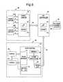
- the target awareness determination systemis shown including the object tracking system 18, the eye gaze monitor system 38, and an HMI controller 60 for providing control output signals to a collision warning system 68.
- the HMI controller 60processes the output signals 26 and 54 and determines a driver awareness condition according to the present invention.
- the HMI controller 60further generates one or more outputs 66 which may be used to adjust parameters, such as thresholds, of the collision warning system 68.
- the object tracking system 18includes radar sensors 12A and 12B and a target monitor 20.
- Target monitor 20preferably includes a microprocessor-based controller having a microprocessor 22 and memory 24.
- Memory 24may include random access memory (RAM), read-only memory (ROM), electrically erasable programmable read-only memory (EEPROM), and other memory as should be evident to those skilled in the art.
- Target monitor 20may be a commercially available off-the-shelf controller and may be dedicated to target tracking, adaptive cruise control or crash processing, according to some examples, or may share processing capability with other vehicle functions.
- the target monitor 20receives the range measurement R, range rate measurement ⁇ and signal amplitude A from each of radar sensors 12A and 12B, and processes the received signals with one or more target tracking routines to determine the position and velocity of the target object 16 relative to the host vehicle 10.
- the target tracking routine(s)may further process the estimated position and velocity to determine whether a potential collision of the target object 16 with the host vehicle 10 may occur or to control some other vehicle function(s).
- the target monitor 20generates output signals 26 that are made available to the HMI controller 60 and may be made available to various other systems.
- the eye gaze monitor system 38includes the first and second video cameras 30 and 40 coupled to a gaze monitor 42.
- Video cameras 30 and 40may include CCD/CMOS active-pixel digital image sensors each mounted as individual chips onto a circuit board.
- CMOS active-pixel digital image sensoris Model No. PB-0330, commercially available from Photobit, which has a resolution of 640 H x 480 V.
- the gaze monitor 42is shown having a frame grabber 44 for receiving the video frames generated by the first and second video cameras 30 and 40.
- the gaze monitor 42includes a vision processor 46 for processing the video frames.
- the gaze monitor 42also includes memory 48, such as RAM, ROM, EEPROM, and other memory as should be evident to those skilled in the art.
- the vision processor 46may be configured to perform one or more routines for identifying and tracking one or more features in the acquired video images, and may be further configured to perform one or more vehicle functions based on the tracked information.
- the eye gaze monitor system 38may identify and track a facial characteristic of the driver 34, such as ocular motility or palpebral fissure, and determine a driver drowsy situation.
- the eye gaze monitor system 38may determine the presence of a distracted or inattentive driver.
- the gaze monitor 42processes the video images containing the facial characteristics and determines an eye gaze vector g ⁇ of one or more eyes 36 of the driver 34 of the vehicle 10, and generates output signals 54 via serial output 40, which are input to the HMI controller 60.
- the digital videomay be input via video ports to vision processor 46, which may then store the images in memory 48.
- the gaze monitor 42has a control function 52 via RS-232 which allows for control of each of the first and second cameras 30 and 40.
- Control of the first and second cameras 30 and 40may include automatic adjustment of the pointing orientation of the first and second cameras 30 and 40.
- the first and second cameras 30 and 40may be repositioned to focus on an identifiable feature, and may scan a region in search of an identifying feature.
- Controlmay include adjustment of focus and magnification as may be necessary to track an identifiable feature.
- the eye gaze monitor system 38may automatically locate and track an identifiable feature, such as the driver's eye 36 and other facial characteristics.
- the HMI controller 60includes a microprocessor-based controller having a microprocessor 62 and memory 64.
- Memory 64may include RAM, ROM, EEPROM, and other memory as should be evident to those skilled in the art.
- the HMI controller 60is programmed to include one or more routines for determining driver awareness of a target object 16 based on the position of the object 16 and the eye gaze vector g ⁇ .
- the HMI controller 60further provides output signals 66 based on the determined driver awareness to a collision warning system 68 and possibly other systems.
- the collision warning system 68may utilize the driver awareness output signals 66 to adjust parameters in the collision warning system 68 such as to provide different thresholds for a visual and/or audible warning to the driver 34 of the vehicle 10.
- the collision warning system 68may change threshold parameters so as to minimize the presence of excessive false alarms.
- the target awareness determination systemis described in connection with a target monitor 20, an eye gaze monitor 42, and an HMI controller 60, each having a microprocessor and memory, it should be appreciated that the target tracking, eye gaze monitoring, and driver awareness determination routines may be implemented in any one or more processors, without departing from the teachings of the present invention.
- an object position and velocity estimator 32is generally shown receiving the range measurements R, range rate measurements ⁇ , and amplitude measurements A from both of sensors 12A and 12B.
- the range R, range rate ⁇ , and amplitude A measurementsare processed by the estimator 32, which includes programmed routines, as shown in FIGS. 5-7 and described in more detail below, to estimate the position and velocity of the target object 16.
- an extended Kalman filteris employed to estimate the object position coordinates x and y and to estimate the velocity components ⁇ and ⁇ of the object 16.
- the non-linear extended Kalman filterinputs a sequence of measurements and, at each measurement time k, k+1, k+2, etc., estimates of the target object attributes for position and velocity at the current time k are updated.
- the estimation problem for the non-linear extended Kalman filteris explained below with the filter state model, process dynamics model, and measurement model.
- X ⁇x x ⁇ y y ⁇
- xis the downrange position coordinate of target object
- ⁇is the downrange relative velocity component of target object
- yis the crossrange position coordinate of target object
- ⁇is the crossrange relative velocity component of target object
- x ⁇ k + 1F ⁇ x ⁇ k + w ⁇ k
- F1 T 0 0 0 1 0 0 0 0 1 T 0 0 0 1
- w ⁇ kis a zero-mean random vector (process noise) having covariance
- Q⁇ x ⁇ T 3 3 ⁇ x ⁇ T 2 2 0 0 ⁇ x ⁇ T 2 2 ⁇ x ⁇ T 0 0 0 0 ⁇ x ⁇ T 3 3 ⁇ x ⁇ T 2 2 0 0 ⁇ x ⁇ T 2 2 ⁇ y ⁇ T
- ⁇ x , ⁇ yare calibrations
- subscripts k and k + 1refer to discrete time instants
- Tis the elapsed time between instants k and k+1.
- R ⁇ 1x 2 + y + d 2 + v 1 Range from sensor 12 ⁇
- a R ⁇ ⁇ 1x ⁇ x ⁇ + y + d ⁇ y ⁇ x 2 + y + d 2 + v 1 Range rate from sensor 12 A
- R cos ⁇ ⁇x + v 3
- Rx 2 + y 2 is the estimated range from the origin O of coordinates
- ⁇is obtained from lookup table using estimated range R and amplitude ratio
- v ⁇is a zero-mean random vector representing measurement errors having covariance as shown below.
- v ⁇v 1 v 2 v 3 v 4
- R ⁇ 2x 2 + y - d 2 + v 1 Range from sensor 12 ⁇ B
- R ⁇ ⁇ 2x ⁇ x ⁇ + y - d ⁇ y ⁇ x 2 + y - d 2 + v 2 Range rate from sensor 12 B
- R cos ⁇ ⁇x + v 3
- Rx 2 + y 2 is the estimated range from the origin O of coordinates
- ⁇is obtained from lookup table using estimated range R and amplitude ratio
- v ⁇is a zero-mean random vector representing measurement errors having covariance as shown below.
- v ⁇v 1 v 2 v 3 v 4
- the target object 16may be further tracked based on the last known position and velocity estimations of the object 16. This may be accomplished by employing a single field of view tracking routine which may include one of the routines disclosed in either of pending U.S. Application Serial No. 10/158,550, filed on May 30, 2002 ( US-A-2003/225517 ), entitled "COLLISION DETECTION SYSTEM AND METHOD OF ESTIMATING MISS DISTANCE,” and U.S. Application Serial No.
- routine 100for estimating the position and velocity of the target object.
- Routine 100begins at step 102 and proceeds to step 104 to receive the sensor measurement data from one of the radar sensors.
- the routine 100applies gating criteria to determine if there is detection of an object of interest from the field of view of the radar sensor.
- decision step 108routine 100 determines if an object is detected by the radar sensor and, if not, returns to step 104. If an object is detected by the radar sensor, routine 100 proceeds to step 110 to store in memory the amplitude A measurement of the returned radar signal received by the radar sensor.
- routine 100determines whether the object of interest is in an overlapping field of view (FOV) coverage zone for multiple radar sensors in step 112.
- FOVoverlapping field of view
- routine 100decides which processing routine is performed based on whether the object detected is determined to be within the overlapping FOV coverage zone. If the object detected is within an overlapping FOV coverage zone, routine 100 proceeds to step 116 to perform a common FOV processing routine, as described in connection with FIG. 6 , before returning to the beginning of routine 100. If the object detected is not within the overlapping coverage zone, routine 100 proceeds to perform a single FOV processing routine in step 118, which is shown in FIG. 7 , before returning to the beginning of routine 100. Routine 100 is repeated each loop so that new data from one of sensors 12A and 12B is introduced during one loop and the new data from the other sensors 12A and 12B is introduced during the next loop.
- routine 120is shown beginning at step 122 and proceeding to step 124 to time-update the extended Kalman filter state based on an elapsed time since the last sensor report.
- routine 120estimates the range R to the object using the time-updated states. Routine 120 then obtains the most recent signal amplitude A measurements from the other sensor for the same object of interest in step 128.
- step 130common FOV processing routine 120 computes the amplitude ratio A R using amplitude measurements A from the current sensor and the most recent amplitude measurement A from the other sensor for the same object of interest.
- the amplitude ratio A Ris based on the most recently acquired data.
- routine 120estimates the azimuth angle ⁇ of the object using range R, the amplitude ratio A R , and a lookup table.
- routine 120computes synthetic measurements (estimations) of object position coordinates x and y using the estimated range R and azimuth angle ⁇ .
- routine 120measurement-updates the filter using range R and range rate ⁇ measurements along with the synthetic position coordinates x and y before returning in step 138.
- the common field of view processing routine 120estimates the position coordinates x and y and velocity components ⁇ and ⁇ of an object 16 by employing an extended Kalman filter based on the sensed range R, range rate ⁇ , and signal amplitude A measurements acquired from at least two radar sensors when the target object 16 is within the overlapping coverage zone 15.
- the single field of view processing routine 140may be performed as shown in FIG. 7 .
- single FOV processing routine 140starts at step 142 and proceeds to step 144 to receive sensor measurement data from a radar sensor.
- routine 140runs a single beam filter using the elapsed time and range R and range rate R measurements as acquired from the appropriate radar sensor covering the single FOV of interest.
- Routine 140extracts the object's speed and miss angle estimates from the single beam filter in step 148 and determines direction of motion of the object across the field of view in step 150.
- routine 140updates the estimates of object position coordinates x and y before returning in step 154.
- FIG. 8An example of the geometry for tracking an object 16 in a non-overlapping field of view with a single field of view tracking algorithm is shown in FIG. 8 .
- the target 16is shown at different time periods k and k+1.
- object 16At time period k, object 16 has position coordinates x k and y k .
- object 16As the object 16 travels during an elapsed time period, object 16 has time-updated position coordinates xk+1 and yk+1.
- the object 16has a magnitude of target velocity vector S k and the target object has a miss angle at time k of ⁇ k .
- the single field of view processing algorithmis able to update the position coordinates x and y of the object based on the object speed S k and miss angle ⁇ k estimates for each consecutive time period increment.
- the single field of view processing routine 140may employ any of a number of algorithms for tracking a target object through a single field of view of a sensor once the position and velocity of the object are obtained. Examples of single field of view processing techniques are disclosed in pending U.S. Application Serial Nos. 10/158,550 ( US-A-2003/225517 ) and 10/159,959 ( US-A-6615138 ), both filed on May 30, 2002.
- the extended Kalman filtermay be designed and implemented to estimate the position and velocity of the target object 16 by employing the state variables, the process model, and the measurement model as described above.
- standard models of process and measurement noisecould be employed.
- the extended Kalman filtermay be implemented in various forms such as a smoother or a non-linear filter which is based on the selection of physical quantities to be represented by state variables in the filter, the dynamic models chosen to represent the interaction and time-evolution of the state variables, and the measurement model chosen to represent how the available measurements are related to the values taken by the physical quantities represented in the state variables.
- the extended Kalman filterhandles non-linearities in the models, particularly in the measurement model.
- the first camera 30is shown focused at an inclination angle ⁇ relative to the horizontal plane of the vehicle 10.
- the inclination angle ⁇is within a range of fifteen to thirty degrees (15° to 30°).
- An inclination angle ⁇ in the range of fifteen to thirty degrees (15° to 30°)provides a clear view of the driver' s ocular features including one or both eyeballs 36 and the pupil of the eyeballs, the superior and inferior eyelids, and the palpebral fissure space between the eyelids.
- the second camera 40is similarly mounted at the same or similar inclination angle ⁇ .
- a gaze vector g ⁇which is the line-of-sight vector of the eyeball 36 of the driver 34.
- the gaze vector g ⁇is the vector at which the eye 36 is focused and is indicative of the line-of-sight direction that the driver 34 of the vehicle 10 realizes.
- the target awareness determination system of the present inventiondetermines an awareness angle ⁇ which is shown in FIG. 10 .
- the awareness angle ⁇is the angle between the gaze vector g ⁇ and a line 74 extending from the driver' s eye 36 to the target object 16.
- the awareness angle ⁇serves as an indication of whether the driver 34 is visually aware of the target object 16.
- the target awareness determination systemuses a recent history of the awareness angle ⁇ to infer the driver' s awareness of the target object 16.
- the eye gaze monitor system 38determines (e.g., estimates) the driver' s head position h ⁇ in three dimensions (x, y, z) as well as three-dimensional coordinates of the gaze vector g ⁇ .
- the eye gaze vector g ⁇is processed in combination with the three-dimensional information about the target object 16 provided by the object tracking system 18 to determine the driver awareness.
- the origin Ois the location either at radar sensor 12A or 12B or is a middle location between sensors 12A and 12B that serves as the average sensor location.
- the coordinates of the driver' s head h ⁇ in this reference systemdepend on the relative position of the driver' head with respect to the eye gaze monitor system 38 (which is an output of the eye gaze monitor system 38) and the relative position of the gaze monitor system with respect to the origin O (which is a known vehicle parameter).
- the target awareness determination systemmonitors the awareness angle ⁇ and, if the awareness angle ⁇ is not less than a predetermined angle of about two degrees (2°) for a minimum time period from the moment the object tracking system detects a new threat-posing or information-caring target object, the system assumes that the driver did not perceive the target object as a threat or new information.
- the predetermined angular threshold of two degrees (2°)is similar to the angular width of the fovea, which is a central area of the retina of the eye 36. In a typical eye-scanning behavior, the driver 34 will immediately foveate the target object 16 when the driver 34 notices the threat developing in the driver' s peripheral vision.
- the eye 36will refocus to the target object such that the awareness angle ⁇ does not exceed the predetermined angle of about two degrees (2°). Furthermore, if the awareness angle ⁇ is less than the predetermined angle for a very short time less than the minimum time period of thirty milliseconds (30 ms), according to one embodiment, which may occur in one video frame, the system does not conclude that the driver 34 has perceived the threat of the object 16, because the driver 34 could be coincidentally saccading across the target object 16 without noticing the object 16.
- the target awareness determination system of the present inventionemploys a recent time history of the awareness angle ⁇ to insure that the awareness angle ⁇ is less than about two degrees (2°) for a minimum time period of at least thirty milliseconds (30 ms) before making a determination that the driver 34 is aware of the target object 16.
- the knowledge of whether or not the driver 34 is aware of the target object 16is useful to adaptively modify the warning parameters of a warning system, such as a collision warning system.
- a warning systemsuch as a collision warning system.
- the driver 34might be monitoring a lateral target while momentarily neglecting a forward target.
- the lateral targetis a vehicle that begins braking
- a side collision warning systemcould be suppressed or delayed.
- the forward visual target that is not being attended tois a vehicle that initiates a braking maneuver
- the forward collision warningcould be presented immediately.
- Adaptively shifting warning thresholds based on the driver awareness determination realized with the awareness angle ⁇will serve to reduce the frequency of nuisance alarms and will further provide useful warnings earlier to the driver 34.
- a forward collision warning systemmay include both cautionary and imminent warning levels.
- the imminent warning level(s)is generally accompanied by an auditory stimulus, but, in order to reduce driver annoyance, the cautionary level may use only a visual stimulus. Because an auditory stimulus is useful for reorienting an inattentive driver to the relevant target object, the cautionary level could be accompanied with an auditory stimulus when the driver 34 is not attending to the relevant target. Because the warnings would only alert the driver 34 when the driver 34 is unaware of the developing threat, this decreases false alarms which reduces driver annoyance.
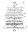
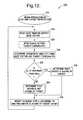
- routine 200for determining the gaze vector g ⁇ of the driver of the vehicle.
- Routine 220for determining a driver awareness condition and modifying warning levels based on the driver awareness condition.
- routine 220determines if the awareness angle ⁇ is less than about two degrees (2°) for more than a predetermined time period of thirty milliseconds (30 ms). If the awareness angle ⁇ is less than about two degrees (2°), routine 220 determines that the driver is aware of the target in step 232. Otherwise, if the awareness angle ⁇ is not less than about two degrees (2°) for the predetermined time period, routine 220 determines that the driver is not aware of the target in step 234. In step 236, routine 220 further modifies warning levels according to whether the driver is aware of the target or not. This may include adaptively shifting warning thresholds in a collision detection system or other warning systems.
- the target awareness determination system of the present inventionadvantageously integrates the object tracking system 18 and eye gaze monitor system 38 to determine whether the driver 34 of the vehicle 10 is aware of a detected target object 16 so as to provide an increased level of security in operating the vehicle 10.
- the target awareness determination systemadvantageously improves vehicle operation for occupants and pedestrians in the vehicle 10, provides more relevant warnings given to the driver 34, minimizes the occurrence of nuisance alarms and thus driver disregard based on nuisance alarms, and better integrates existing vehicle systems.
Landscapes
- Engineering & Computer Science (AREA)
- Radar, Positioning & Navigation (AREA)
- Remote Sensing (AREA)
- Physics & Mathematics (AREA)
- Health & Medical Sciences (AREA)
- Life Sciences & Earth Sciences (AREA)
- General Physics & Mathematics (AREA)
- Computer Networks & Wireless Communication (AREA)
- Mechanical Engineering (AREA)
- General Health & Medical Sciences (AREA)
- Molecular Biology (AREA)
- Veterinary Medicine (AREA)
- Psychology (AREA)
- Social Psychology (AREA)
- Hospice & Palliative Care (AREA)
- Biophysics (AREA)
- Pathology (AREA)
- Biomedical Technology (AREA)
- Heart & Thoracic Surgery (AREA)
- Medical Informatics (AREA)
- Educational Technology (AREA)
- Surgery (AREA)
- Animal Behavior & Ethology (AREA)
- Developmental Disabilities (AREA)
- Public Health (AREA)
- Psychiatry (AREA)
- Theoretical Computer Science (AREA)
- Multimedia (AREA)
- Child & Adolescent Psychology (AREA)
- Mathematical Physics (AREA)
- Transportation (AREA)
- Automation & Control Theory (AREA)
- Computer Vision & Pattern Recognition (AREA)
- Emergency Management (AREA)
- Business, Economics & Management (AREA)
- Ophthalmology & Optometry (AREA)
- Human Computer Interaction (AREA)
- Traffic Control Systems (AREA)
- Crystals, And After-Treatments Of Crystals (AREA)
- Fittings On The Vehicle Exterior For Carrying Loads, And Devices For Holding Or Mounting Articles (AREA)
Abstract
Description
- The present invention generally relates to systems, such as collision warning and avoidance systems, for detecting objects and, more particularly, relates to a system and method of determining driver awareness of an object.
- Automotive vehicles are increasingly being equipped with collision avoidance and warning systems for predicting a high probability collision event with an object, such as another vehicle or a pedestrian. Upon detecting a potential collision event, such systems typically initiate safety-related countermeasure actions to avoid the collision and/or provide a warning to the vehicle operator. The ability to accurately predict a potential upcoming collision also enables a vehicle controller to evoke an appropriate safety-related countermeasure, such as initiate an avoidance chassis action (e.g., steer, brake and/or throttle) and/or deploy safety-related devices and/or deploy a warning signal to notify the vehicle operator of a predicted collision with an object.
- Video image tracking systems have also been proposed for use on vehicles for tracking the face, including the eyes, of the driver to allow for determination of various facial characteristics of the driver including position, orientation, and movement of the driver's eyes, face, and head. By knowing the driver's facial characteristics, such as the driver's eye gaze, ocular data, head position, and other characteristics, vehicle control systems can provide enhanced vehicle functions. For example, vehicle control systems can advise the driver of driver distraction, driver inattention, or other drowsy driver situations.
- Conventional collision warning/avoidance systems are generally considered an integration of an object tracking system comprised of an active detection sensor, such as a radar or lidar, in order to detect objects and provide estimates of their kinematic parameters (e.g., range, speed, and angle), and a threat determination and response system to assess a level of threat and determine the composition of safety-related countermeasures to be present to the driver. The response time initiation and composition of the appropriate safety-related countermeasure is highly dependent on the situational awareness of the driver. As such, in such a system implementation, there may exist errors in when the warning is provided and providing a warning level that is appropriate to the situational awareness of thedriver of the vehicle. When the driver is attentive, conventional collision warning systems may be perceived to provide excessive false warnings/alarms which may result in the driver disregarding warnings that are given. Contrarily, any resultant delays in reaction caused by driver unawareness of an associated risk may put the driver and other vehicle passengers at greater risk.
- Accordingly, it is desirable to provide for a system that can determine the awareness of the driver to the surrounding environment and can enhance the performance delivered with a collision warning system. In particular, it is desirable to provide for an integrated system that minimizes false warnings/alarms that may be provided to a driver, particularly for use in a vehicle collision warning system.
DE-A-4338244 discloses a system in accordance with the preamble of claim 1.- The present invention provides for an object awareness determination system and method of determining awareness of a user to an object as defined in
claims 1 and 9. According to one embodiment, the system determines awareness of the driver of a vehicle to a detected object. The system includes an object monitor having an object detection sensor for sensing an object in a field of view and determining a position of the object. The system also includes an eye gaze monitor having an imaging camera oriented to capture images of a user, including an eye of the user. The eye gaze monitor determines an eye gaze vector. The system further includes a controller for determining awareness of the user of an object based on the detected object position and the eye gaze vector. - The method of determining user awareness of an object includes the steps of sensing the presence of an object in a field of view, and determining a position of the object within the field of view. The method also includes the steps of monitoring eye gaze of a user, determining a gaze vector, and determining user awareness of the object as a function of the position of the object and the gaze vector.
- Accordingly, the driver awareness determination system and method of the present invention advantageously integrates the eye gaze monitor and the object monitor to ensure that the driver is aware of target objects.
- Thereby, the proposed invention allows the integration of a driver awareness determination systems, object tracking system, and threat assessment and response system such that an adaptive situational tailored safety-related countermeasure response is generated. As such, in the determination of a high potential collision event, the response time initiation and composition of the appropriate safety-related countermeasure is adaptively determined dependent on the situational awareness of the driver. This advantageously allows for the reduction of excessive false alarms which may otherwise occur in a conventional collision warning system.
- These and other features, advantages and objects of the present invention will be further understood and appreciated by those skilled in the art by reference to the following specification, claims and appended drawings.
- The present invention will now be described, by way of example, with reference to the accompanying drawings, in which:
FIG. 1 is a plan view of a vehicle illustrating the geometry of sensor arrangements for a driver awareness determination system according to the present invention;FIG. 2 is a plan view further illustrating the geometry of an object tracking system for tracking a target object;FIG. 3 is a block diagram illustrating the driver awareness determination system according to the present invention;FIG. 4 is a block diagram illustrating an object position and velocity estimator of the object tracking system;FIG. 5 is a flow diagram illustrating a routine for tracking an object according to the present invention;FIG. 6 is a flow diagram illustrating a routine for estimating object position and velocity when the object is in an overlapping coverage zone;FIG. 7 is a flow diagram illustrating a routine for estimating object position and velocity when the object travels in a sensor field of view outside of the overlapping coverage zone;FIG. 8 is a plan view further illustrating the geometry of tracking the object in a single field of view;FIG. 9 is a side perspective view of the projection of one of the video cameras towards the face of the driver;FIG. 10 is a plan view illustrating the geometry for determining an awareness angle;FIG. 11 is a flow diagram illustrating a routine for determining a gaze vector of the driver of the vehicle; andFIG. 12 is a routine integrating gaze and target information to determine driver awareness of an object and modify warning levels.- Referring to
FIG. 1 , anautomotive vehicle 10 is generally illustrated having a target awareness determination system which integrates an object tracking monitor and an eye gaze monitor. The target awareness detection system monitors the position of an object as determined by the object tracking monitor, and further monitors the gaze vector of adriver 34 of thevehicle 10. The driver awareness determination system further determines if thedriver 34 is aware of the object as a function of the object location and the eye gaze vector. By knowing whether or not thedriver 34 is aware of the object, the target awareness determination system can advantageously be used to adaptively modify warning parameters in a collision warning system or other countermeasure system. - The target awareness determination system is shown and described herein in connection with a radar-based object tracking monitor (also referred to herein as an object tracking system) similar to that disclosed in
U.S. Application Serial No. 10/196,631 (US-A-2004/012516 ) and a dual-camera eye gaze monitor (also referred to herein as gaze monitor system) having a camera arrangement similar to that disclosed inU.S. Application Serial No. 10/103,202 (US-A-2003/201895 ). However, it should be appreciated that other object tracking systems and eye gaze monitor systems could be employed in connection with the present invention. - The object tracking system is useful for detecting and tracking one or more objects, and may be further useful for predicting the potential collision of the object(s) with the
host vehicle 10. The ability to predict the potential collision between the vehicle and an object using an object tracking system can be achieved by a variety of methods using either single or multiple active detection sensors, such as lidar, radar, or vision. - One such single sensor object tracking system implementation approach, uses a single narrow beamwidth radar and/or lidar signal that is mechanically swept over a large field of view. Within the sensor coverage field, the object tracking system has the ability to detect and track one or more stationary and/or non-stationary objects. Additionally, for each sensed object, the system provides the estimates of the velocity and relative position (e.g., range and angle), and assesses whether this object is in path with the host vehicle.
- Another such implementation of an object tracking system includes a plurality of overlapping
radar sensors vehicle 10 to cover a desired field of view, shown in front of thevehicle 10. According to the embodiment shown, the object tracking system has tworadar sensors vehicle 10.Radar sensor 12A detects objects within a first field ofview 14A, andradar sensor 12B detects objects within a second field of view 14B. Theradar sensors view 14A and 14B partially overlap to provide anoverlapping coverage zone 15. The fields ofview 14A and 14B also have non-overlapping regions. - The object tracking system senses and tracks one or more objects, such as a moving target, and estimates the position and velocity of the sensed target object, relative to the
host vehicle 10. By estimating the current position and velocity of the target object within theoverlapping coverage zone 15, thehost vehicle 10 is able to track the object moving through the overlappingcoverage zone 15 as well as through non-overlapping fields of view. It should be appreciated that the estimated position and velocity may be useful in tracking an object for purposes of determining collision detection and avoidance, such that responsive action may be taken to avoid a collision or to minimize the effects of a collision. - The eye gaze monitor system is shown employing a pair of
video imaging cameras driver 34 of thevehicle 10. The first andsecond video cameras vehicle 10 which allow for the acquisition of facial characteristics of thedriver 34 including one or twoeyes 36. Thevideo cameras driver 34 of thevehicle 10 is expected to be located during normal vehicle driving. More particularly, the images capture the driver's face, including one or botheyes 36 and the surrounding ocular features generally formed in the area referred to as the ocular adnexa. - The object tracking sensor arrangement shown includes a pair of
sensors sensors view 14A and 14B. Each ofsensors FIG. 2 , to atarget object 16, measures the range rate (time rate of change of radial distance) Ṙ1 and Ṙ2 oftarget object 16, and further measures the received return radar signal amplitude A. The range R is the estimated radial distance between thehost vehicle 10 and theobject 16, and R1 and R2 represent the sensed range fromsensors object 16 as a function of time relative to thehost vehicle 10. The signal amplitude A is the amplitude of the reflected and returned radar signal received at each sensor. Sensors Sensors target object 16.- The object tracking system described herein determines the position and velocity of the
target object 16 as a function of the range R, range rate Ṙ and signal amplitude A received atsensors object 16. Thus, the target tracking system is able to use a reduced complexity and less costly sensing arrangement. While a pair ofsensors vehicle 10. - The tracking system estimates the position and velocity of the
target object 16 when theobject 16 is in the overlappingcoverage zone 15 sensed by multiple sensors, and continues to track theobject 16 as it moves through the overlappingcoverage zone 15 and non-overlapping zones within the first and second fields ofview 14A and 14B. When thetarget object 16 is in the overlappingcoverage zone 15, an extended Kalman filter is employed to estimate the position and velocity of theobject 16 using range and range rate triangulation and a signal amplitude ratio AR. When theobject 16 is outside of the overlappingcoverage zone 15, but remains within one of the first and second fields ofview 14A and 14B, the object tracking system continues to track theobject 16 by employing a single beam tracking algorithm using the current measurements and the last known position and velocity when in the overlappingcoverage zone 15. This single beam tracking algorithm may estimate an azimuth angular rate using range and range rate measurements. - In order to track an
object 16 in the overlappingcoverage zone 15, theobject 16 may be assumed to be a point reflector. As shown inFIG. 2 , thesensors vehicle 10. The angle θ may be determined as a function of the range and amplitude of the signals received bysensors sensors coverage zone 15 of the twosensors object 16. Amplitude ratio AR refers to the ratio of the sensed amplitudes of the received signal returns from the twosensors 12A and 12b. A synthetic measurement (estimation) of azimuth angle may thus be constructed from the two amplitude measurements for a given target range. Synthetic measurements of position coordinates (x, y) are then constructed using the azimuth angle and the estimated range midway betweensensors sensors - Since the relationship between the state variables and the predicted measurements are not linear, a non-linear filter, preferably an extended Kalman filter, is used. It should be appreciated that other non-linear filters could be employed, such as an unscented Kalman filter or a particle filter. The measurement noise covariance matrix, which statistically describes the anticipated errors in the various measurements, is used to tune the filter response to range, range rate, and received signal amplitude measurements. The extended Kalman filter further provides a time update which describes how the state variables are believed to evolve in time. The state variables are two position coordinates x and y and two velocity components ẋ and ẏ. The position states evolve in the usual linear way according to the corresponding velocities. The velocities are modeled as random walks which are roughly constant but change slowly. A process noise covariance matrix describes the levels of the uncertainties in the above model and, in particular, allows for tuning. Mathematical models of process dynamics and measurements are shown and described herein.
- Referring to
FIG. 3 , the target awareness determination system is shown including theobject tracking system 18, the eyegaze monitor system 38, and anHMI controller 60 for providing control output signals to acollision warning system 68. TheHMI controller 60 processes the output signals 26 and 54 and determines a driver awareness condition according to the present invention. TheHMI controller 60 further generates one ormore outputs 66 which may be used to adjust parameters, such as thresholds, of thecollision warning system 68. - The
object tracking system 18 includesradar sensors target monitor 20. Target monitor 20 preferably includes a microprocessor-based controller having amicroprocessor 22 andmemory 24.Memory 24 may include random access memory (RAM), read-only memory (ROM), electrically erasable programmable read-only memory (EEPROM), and other memory as should be evident to those skilled in the art. Target monitor 20 may be a commercially available off-the-shelf controller and may be dedicated to target tracking, adaptive cruise control or crash processing, according to some examples, or may share processing capability with other vehicle functions. - The target monitor 20 receives the range measurement R, range rate measurement Ṙ and signal amplitude A from each of
radar sensors target object 16 relative to thehost vehicle 10. The target tracking routine(s) may further process the estimated position and velocity to determine whether a potential collision of thetarget object 16 with thehost vehicle 10 may occur or to control some other vehicle function(s). The target monitor 20 generates output signals 26 that are made available to theHMI controller 60 and may be made available to various other systems. - The eye
gaze monitor system 38 includes the first andsecond video cameras gaze monitor 42.Video cameras - The gaze monitor 42 is shown having a
frame grabber 44 for receiving the video frames generated by the first andsecond video cameras vision processor 46 for processing the video frames. The gaze monitor 42 also includesmemory 48, such as RAM, ROM, EEPROM, and other memory as should be evident to those skilled in the art. Thevision processor 46 may be configured to perform one or more routines for identifying and tracking one or more features in the acquired video images, and may be further configured to perform one or more vehicle functions based on the tracked information. For example, the eyegaze monitor system 38 may identify and track a facial characteristic of thedriver 34, such as ocular motility or palpebral fissure, and determine a driver drowsy situation. According to another example, the eyegaze monitor system 38 may determine the presence of a distracted or inattentive driver. The gaze monitor 42 processes the video images containing the facial characteristics and determines an eye gaze vector g̅ of one ormore eyes 36 of thedriver 34 of thevehicle 10, and generates output signals 54 viaserial output 40, which are input to theHMI controller 60. In lieu of theframe grabber 44, it should be appreciated that the digital video may be input via video ports tovision processor 46, which may then store the images inmemory 48. - Further, the gaze monitor 42 has a
control function 52 via RS-232 which allows for control of each of the first andsecond cameras second cameras second cameras second cameras gaze monitor system 38 may automatically locate and track an identifiable feature, such as the driver'seye 36 and other facial characteristics. - The
HMI controller 60 includes a microprocessor-based controller having amicroprocessor 62 andmemory 64.Memory 64 may include RAM, ROM, EEPROM, and other memory as should be evident to those skilled in the art. TheHMI controller 60 is programmed to include one or more routines for determining driver awareness of atarget object 16 based on the position of theobject 16 and the eye gaze vector g̅. TheHMI controller 60 further provides output signals 66 based on the determined driver awareness to acollision warning system 68 and possibly other systems. Thecollision warning system 68 may utilize the driver awareness output signals 66 to adjust parameters in thecollision warning system 68 such as to provide different thresholds for a visual and/or audible warning to thedriver 34 of thevehicle 10. For example, when theHMI controller 60 determines that thedriver 34 is aware of anobject 16, thecollision warning system 68 may change threshold parameters so as to minimize the presence of excessive false alarms. While the target awareness determination system is described in connection with atarget monitor 20, aneye gaze monitor 42, and anHMI controller 60, each having a microprocessor and memory, it should be appreciated that the target tracking, eye gaze monitoring, and driver awareness determination routines may be implemented in any one or more processors, without departing from the teachings of the present invention. - Referring to
FIG. 4 , an object position andvelocity estimator 32 is generally shown receiving the range measurements R, range rate measurements Ṙ, and amplitude measurements A from both ofsensors estimator 32, which includes programmed routines, as shown inFIGS. 5-7 and described in more detail below, to estimate the position and velocity of thetarget object 16. - When the
target object 16 is located within the overlappingcoverage zone 15, an extended Kalman filter is employed to estimate the object position coordinates x and y and to estimate the velocity components ẋ and ẏ of theobject 16. The non-linear extended Kalman filter inputs a sequence of measurements and, at each measurement time k, k+1, k+2, etc., estimates of the target object attributes for position and velocity at the current time k are updated. The estimation problem for the non-linear extended Kalman filter is explained below with the filter state model, process dynamics model, and measurement model. 


sensors 


sensors 
- When the
target object 16 leaves the overlappingcoverage zone 15 and remains within one of the field ofviews 14A and 14B, thetarget object 16 may be further tracked based on the last known position and velocity estimations of theobject 16. This may be accomplished by employing a single field of view tracking routine which may include one of the routines disclosed in either of pendingU.S. Application Serial No. 10/158,550, filed on May 30, 2002 US-A-2003/225517 ), entitled "COLLISION DETECTION SYSTEM AND METHOD OF ESTIMATING MISS DISTANCE," andU.S. Application Serial No. 10/159,959 (US-A-6615138), filed on May 30, 2002 , entitled "COLLISION DETECTION SYSTEM AND METHOD OF ESTIMATING MISS DISTANCE EMPLOYING CURVE FITTING". The techniques described in the aforementioned applications can determine the azimuth angular rate of atarget object 16 using range and range rate measurements by estimating the range and speed of the object along with the magnitude of a miss angle which is the angle between the radar sensor to the object and the object's velocity vector. Given the last known position and velocity of theobject 16 acquired in the overlappingcoverage zone 15, the trajectory of theobject 16 can be estimated until theobject 16 leaves the fields ofview 14A and 14B. - Referring to
FIG. 5 , a routine 100 is illustrated for estimating the position and velocity of the target object.Routine 100 begins atstep 102 and proceeds to step 104 to receive the sensor measurement data from one of the radar sensors. Next, instep 106, the routine 100 applies gating criteria to determine if there is detection of an object of interest from the field of view of the radar sensor. Indecision step 108, routine 100 determines if an object is detected by the radar sensor and, if not, returns to step 104. If an object is detected by the radar sensor, routine 100 proceeds to step 110 to store in memory the amplitude A measurement of the returned radar signal received by the radar sensor. Next, routine 100 determines whether the object of interest is in an overlapping field of view (FOV) coverage zone for multiple radar sensors instep 112. Indecision step 114, routine 100 decides which processing routine is performed based on whether the object detected is determined to be within the overlapping FOV coverage zone. If the object detected is within an overlapping FOV coverage zone, routine 100 proceeds to step 116 to perform a common FOV processing routine, as described in connection withFIG. 6 , before returning to the beginning ofroutine 100. If the object detected is not within the overlapping coverage zone, routine 100 proceeds to perform a single FOV processing routine instep 118, which is shown inFIG. 7 , before returning to the beginning ofroutine 100.Routine 100 is repeated each loop so that new data from one ofsensors other sensors - Referring to
FIG. 6 , the common field ofview processing routine 120 is shown beginning atstep 122 and proceeding to step 124 to time-update the extended Kalman filter state based on an elapsed time since the last sensor report. Next, instep 126, routine 120 estimates the range R to the object using the time-updated states.Routine 120 then obtains the most recent signal amplitude A measurements from the other sensor for the same object of interest instep 128. - In
step 130, commonFOV processing routine 120 computes the amplitude ratio AR using amplitude measurements A from the current sensor and the most recent amplitude measurement A from the other sensor for the same object of interest. Thus, the amplitude ratio AR is based on the most recently acquired data. Instep 132, routine 120 estimates the azimuth angle θ of the object using range R, the amplitude ratio AR, and a lookup table. Proceeding to step 134, routine 120 computes synthetic measurements (estimations) of object position coordinates x and y using the estimated range R and azimuth angle θ. Finally, instep 136, routine 120 measurement-updates the filter using range R and range rate Ṙ measurements along with the synthetic position coordinates x and y before returning instep 138. - Accordingly, the common field of
view processing routine 120 estimates the position coordinates x and y and velocity components ẋ and ẏ of anobject 16 by employing an extended Kalman filter based on the sensed range R, range rate Ṙ, and signal amplitude A measurements acquired from at least two radar sensors when thetarget object 16 is within the overlappingcoverage zone 15. When thetarget object 16 leaves the overlappingcoverage zone 15 and remains within one of the non-overlapping fields ofview 14A and 14B, the single field ofview processing routine 140 may be performed as shown inFIG. 7 . - Referring to
FIG. 7 , singleFOV processing routine 140 starts atstep 142 and proceeds to step 144 to receive sensor measurement data from a radar sensor. Next, instep 146, routine 140 runs a single beam filter using the elapsed time and range R and range rate R measurements as acquired from the appropriate radar sensor covering the single FOV of interest.Routine 140 then extracts the object's speed and miss angle estimates from the single beam filter instep 148 and determines direction of motion of the object across the field of view instep 150. Finally, instep 152, routine 140 updates the estimates of object position coordinates x and y before returning instep 154. - An example of the geometry for tracking an
object 16 in a non-overlapping field of view with a single field of view tracking algorithm is shown inFIG. 8 . Thetarget 16 is shown at different time periods k and k+1. At time period k, object 16 has position coordinates xk and yk. As theobject 16 travels during an elapsed time period, object 16 has time-updated position coordinates xk+1 and yk+1. Theobject 16 has a magnitude of target velocity vector Sk and the target object has a miss angle at time k of γk. The single field of view processing algorithm is able to update the position coordinates x and y of the object based on the object speed Sk and miss angle γk estimates for each consecutive time period increment. - It should be appreciated that the single field of
view processing routine 140 may employ any of a number of algorithms for tracking a target object through a single field of view of a sensor once the position and velocity of the object are obtained. Examples of single field of view processing techniques are disclosed in pendingU.S. Application Serial Nos. 10/158,550 (US-A-2003/225517 ) and10/159,959 US-A-6615138 ), both filed on May 30, 2002. - It should be appreciated that the extended Kalman filter may be designed and implemented to estimate the position and velocity of the
target object 16 by employing the state variables, the process model, and the measurement model as described above. In addition, standard models of process and measurement noise could be employed. The extended Kalman filter may be implemented in various forms such as a smoother or a non-linear filter which is based on the selection of physical quantities to be represented by state variables in the filter, the dynamic models chosen to represent the interaction and time-evolution of the state variables, and the measurement model chosen to represent how the available measurements are related to the values taken by the physical quantities represented in the state variables. The extended Kalman filter handles non-linearities in the models, particularly in the measurement model. It should be appreciated that extended Kalman filters have been employed in automotive applications such as vehicle rollover sensing as disclosed inU.S. Patent No. 6,002,974 , entitled "VEHICLE ROLLOVER SENSING USING EXTENDED KALMAN FILTER". - Referring to
FIG. 9 , thefirst camera 30 is shown focused at an inclination angle β relative to the horizontal plane of thevehicle 10. The inclination angle β is within a range of fifteen to thirty degrees (15° to 30°). An inclination angle β in the range of fifteen to thirty degrees (15° to 30°) provides a clear view of the driver' s ocular features including one or botheyeballs 36 and the pupil of the eyeballs, the superior and inferior eyelids, and the palpebral fissure space between the eyelids. Thesecond camera 40 is similarly mounted at the same or similar inclination angle β. Also shown is a gaze vector g̅ which is the line-of-sight vector of theeyeball 36 of thedriver 34. The gaze vector g̅ is the vector at which theeye 36 is focused and is indicative of the line-of-sight direction that thedriver 34 of thevehicle 10 realizes. - The target awareness determination system of the present invention determines an awareness angle φ which is shown in
FIG. 10 . The awareness angle φ is the angle between the gaze vector g̅ and aline 74 extending from the driver' seye 36 to thetarget object 16. The awareness angle φ serves as an indication of whether thedriver 34 is visually aware of thetarget object 16. The target awareness determination system uses a recent history of the awareness angle φ to infer the driver' s awareness of thetarget object 16. The eyegaze monitor system 38 determines (e.g., estimates) the driver' s head position h̅ in three dimensions (x, y, z) as well as three-dimensional coordinates of the gaze vector g̅. The three-dimensional coordinates of the gaze vector g̅ may be represented as g̅ = (gx, gy, gz). The eye gaze vector g̅ is processed in combination with the three-dimensional information about thetarget object 16 provided by theobject tracking system 18 to determine the driver awareness. - The origin O is the location either at
radar sensor sensors object target 16 represented by target coordinates t̅ = (tx, ty, tz). The coordinates of the driver' s head h̅ in this reference system depend on the relative position of the driver' head with respect to the eye gaze monitor system 38 (which is an output of the eye gaze monitor system 38) and the relative position of the gaze monitor system with respect to the origin O (which is a known vehicle parameter). Hence, the three-dimensional coordinates of the driver's head may be represented as h̅ = (hx, hy, hz). Given the gaze vector g̅, head coordinates h̅ and target coordinates t̅, the awareness angle φ can be determined from the following formula:
- The target awareness determination system monitors the awareness angle φ and, if the awareness angle φ is not less than a predetermined angle of about two degrees (2°) for a minimum time period from the moment the object tracking system detects a new threat-posing or information-caring target object, the system assumes that the driver did not perceive the target object as a threat or new information. The predetermined angular threshold of two degrees (2°) is similar to the angular width of the fovea, which is a central area of the retina of the
eye 36. In a typical eye-scanning behavior, thedriver 34 will immediately foveate thetarget object 16 when thedriver 34 notices the threat developing in the driver' s peripheral vision. In doing so, theeye 36 will refocus to the target object such that the awareness angle φ does not exceed the predetermined angle of about two degrees (2°). Furthermore, if the awareness angle φ is less than the predetermined angle for a very short time less than the minimum time period of thirty milliseconds (30 ms), according to one embodiment, which may occur in one video frame, the system does not conclude that thedriver 34 has perceived the threat of theobject 16, because thedriver 34 could be coincidentally saccading across thetarget object 16 without noticing theobject 16. Thus, the target awareness determination system of the present invention employs a recent time history of the awareness angleø to insure that the awareness angle φ is less than about two degrees (2°) for a minimum time period of at least thirty milliseconds (30 ms) before making a determination that thedriver 34 is aware of thetarget object 16. - The knowledge of whether or not the
driver 34 is aware of thetarget object 16 is useful to adaptively modify the warning parameters of a warning system, such as a collision warning system. For example, thedriver 34 might be monitoring a lateral target while momentarily neglecting a forward target. During this time, if the lateral target is a vehicle that begins braking, a side collision warning system could be suppressed or delayed. However, if the forward visual target that is not being attended to is a vehicle that initiates a braking maneuver, the forward collision warning could be presented immediately. Adaptively shifting warning thresholds based on the driver awareness determination realized with the awareness angle φ will serve to reduce the frequency of nuisance alarms and will further provide useful warnings earlier to thedriver 34. - Many forward collision warning systems use one or more levels of warning(s). For example, a forward collision warning system may include both cautionary and imminent warning levels. The imminent warning level(s) is generally accompanied by an auditory stimulus, but, in order to reduce driver annoyance, the cautionary level may use only a visual stimulus. Because an auditory stimulus is useful for reorienting an inattentive driver to the relevant target object, the cautionary level could be accompanied with an auditory stimulus when the
driver 34 is not attending to the relevant target. Because the warnings would only alert thedriver 34 when thedriver 34 is unaware of the developing threat, this decreases false alarms which reduces driver annoyance. - Referring to
FIG. 11 , a routine 200 is shown for determining the gaze vector g̅ of the driver of the vehicle. The routine 200 begins atstep 202 and proceeds to step 204 to detect facial features of the driver including the eye pupils, eye corners, nostrils, upper lip, and other features. Once the facial features of the head of the driver are detected, routine 200 determines the three-dimensional coordinates of the facial features of the driver' s head using triangulation and tracks the facial features over time instep 206. Next, routine 200 calculates the face orientation vector of the driver' s head h̅ = (hx, hy, hz) with regard to the vehicle, and further calculates the gaze vector with regard to the driver' s face orientation, instep 208. Finally, instep 210, routine 200 uses the face orientation vectorh̅ and gaze vector with regard thereto to determine the eye gaze vector h̅ = (gx, gy, gz) with regard to the vehicle (car), before returning to step 204. - Referring to
FIG. 12 , a routine 220 is shown for determining a driver awareness condition and modifying warning levels based on the driver awareness condition.Routine 220 begins atstep 222 and proceeds to read the eye gaze monitor output, which is the gaze vector h̅ = (gx, gy, gz), instep 224. Next, instep 226, routine 220 reads the radar output, which are the target coordinates t̅ = (tx, ty, tz). Proceeding to step 228, routine 220 determines the awareness angle φ using the gaze vector g̅ and the target coordinates t̅. Indecision step 230, routine 220 determines if the awareness angle φ is less than about two degrees (2°) for more than a predetermined time period of thirty milliseconds (30 ms). If the awareness angle φ is less than about two degrees (2°), routine 220 determines that the driver is aware of the target instep 232. Otherwise, if the awareness angle φ is not less than about two degrees (2°) for the predetermined time period, routine 220 determines that the driver is not aware of the target instep 234. Instep 236, routine 220 further modifies warning levels according to whether the driver is aware of the target or not. This may include adaptively shifting warning thresholds in a collision detection system or other warning systems. - Accordingly, the target awareness determination system of the present invention advantageously integrates the
object tracking system 18 and eyegaze monitor system 38 to determine whether thedriver 34 of thevehicle 10 is aware of a detectedtarget object 16 so as to provide an increased level of security in operating thevehicle 10. The target awareness determination system advantageously improves vehicle operation for occupants and pedestrians in thevehicle 10, provides more relevant warnings given to thedriver 34, minimizes the occurrence of nuisance alarms and thus driver disregard based on nuisance alarms, and better integrates existing vehicle systems.


Claims (15)
- A target awareness determination system for determining user awareness of an object, said system comprising:an object monitor (18) including an object detection sensor (12A) for sensing an object (16) in a field of view and determining a position of the object (16);an eye gaze monitor (38) for determining the user's line of sight; anda controller (30) for determining awareness of a driver to the object based on the determined line of sight and of the detected positioned of the object;characterized in that
the eye gaze monitor (38) includes an imaging camera (30) oriented to capture images of a user (34) including an eye of (36) the user (34), said eye gaze monitor (38) determining an eye gaze vector (g̅) indicative of the user's line of sight;
in that the controller (60) determines awareness of the user (34) to the object (16) based on the eye gaze vector (g̅); and
in that the controller (60) generates an output signal (66) for modifying a collision warning system (68) as a function of the determination of user awareness to the object (16). - The system as defined in claim 1, wherein the user (34) is a driver of a vehicle (10) and the controller (60) determines awareness of the driver (34) of the vehicle (10) to an object (16) sensed by the object detection sensor (12A) located on the vehicle (10).
- The system as defined in claim 1, wherein the controller (60) further determines an awareness angle (φ) as a function of the gaze vector (
g ) and the position of the object (16), wherein the controller (60) determines driver awareness as a function of the awareness angle (φ). - The system as defined in claim 3, wherein the controller (60) determines awareness of the user (34) to the object (16) when the awareness angle (φ) is less than a predetermined angle.
- The system as defined in claim 4, wherein the predetermined angle is about two degrees.
- The system as defined in claim 1, wherein the controller (60) determines awareness of the user (34) to the object (16) when the awareness angle (φ) is less than the predetermined angle for a predetermined time period.
- The system as defined in claim 6, wherein the predetermined time period is at least 30 milliseconds.
- The system as defined in claim 1, wherein the object detection sensor (12A) comprises a radar sensor, and the imaging camera (30) comprises a video camera.
- A method of determining user awareness of an object, said method comprising the steps of:sensing the presence of an object (16) in a field of view;determining a position of the object (16) within the field of view;monitoring eye gaze of a user (34);determining an eye gaze vector (
g ) of the user (34);determining user awareness of the object (16) as a function of the position of the object (16) and the eye gaze vector (g̅); andgenerating an output signal (66) for modifying a collision warning system (68) as a function of the determination of user awareness to the object (16). - The method as defined in claim 9 further comprising the steps of:determining an awareness angle (φ) as a function of the eye gaze vector (
g ) and the position of the object (16); anddetermining the user awareness as a function of the awareness angle (φ). - The method as defined in claim 10, wherein the step of determining user awareness further comprises comparing the awareness angle (φ) to a predetermined angle.
- The method as defined in claim 11, wherein the predetermined angle is about two degrees.
- The method as defined in claim 10, wherein the step of determining user awareness comprises comparing the awareness angle (φ) to a predetermined angle for a predetermined time period.
- The method as defined in claim 13, wherein the predetermined time period is at least 30 milliseconds.
- The method as defined in claim 9, wherein the method is performed on a vehicle (10) to determine awareness of a driver (34) of the vehicle (10).
Applications Claiming Priority (2)
| Application Number | Priority Date | Filing Date | Title |
|---|---|---|---|
| US452756 | 2003-06-02 | ||
| US10/452,756US6989754B2 (en) | 2003-06-02 | 2003-06-02 | Target awareness determination system and method |
Publications (2)
| Publication Number | Publication Date |
|---|---|
| EP1484014A1 EP1484014A1 (en) | 2004-12-08 |
| EP1484014B1true EP1484014B1 (en) | 2009-08-12 |
Family
ID=33159505
Family Applications (1)
| Application Number | Title | Priority Date | Filing Date |
|---|---|---|---|
| EP20040076522Expired - LifetimeEP1484014B1 (en) | 2003-06-02 | 2004-05-24 | Target awareness determination system and method |
Country Status (4)
| Country | Link |
|---|---|
| US (1) | US6989754B2 (en) |
| EP (1) | EP1484014B1 (en) |
| AT (1) | ATE439087T1 (en) |
| DE (1) | DE602004022484D1 (en) |
Families Citing this family (155)
| Publication number | Priority date | Publication date | Assignee | Title |
|---|---|---|---|---|
| US7310440B1 (en)* | 2001-07-13 | 2007-12-18 | Bae Systems Information And Electronic Systems Integration Inc. | Replacement sensor model for optimal image exploitation |
| DE10339647A1 (en)* | 2003-08-28 | 2005-03-24 | Robert Bosch Gmbh | Device for driver warning |
| ITTO20030662A1 (en)* | 2003-08-29 | 2005-02-28 | Fiat Ricerche | VIRTUAL VISUALIZATION ARRANGEMENT FOR A FRAMEWORK |
| GB2412431B (en)* | 2004-03-25 | 2007-11-07 | Hewlett Packard Development Co | Self-calibration for an eye tracker |
| ES2568506T3 (en)* | 2004-06-18 | 2016-04-29 | Tobii Ab | Eye control of computer equipment |
| JP4622544B2 (en)* | 2005-01-27 | 2011-02-02 | アイシン精機株式会社 | Vehicle driving support device |
| US20060210111A1 (en)* | 2005-03-16 | 2006-09-21 | Dixon Cleveland | Systems and methods for eye-operated three-dimensional object location |
| US7835834B2 (en)* | 2005-05-16 | 2010-11-16 | Delphi Technologies, Inc. | Method of mitigating driver distraction |
| JP4349350B2 (en)* | 2005-09-05 | 2009-10-21 | トヨタ自動車株式会社 | Mounting structure of face image camera |
| JP2007094618A (en)* | 2005-09-28 | 2007-04-12 | Omron Corp | Notification controller and notification control method, recording medium, and program |
| JP4926437B2 (en)* | 2005-09-28 | 2012-05-09 | 富士重工業株式会社 | Vehicle driving support device |
| CN101356078B (en)* | 2005-12-12 | 2012-07-18 | 松下电器产业株式会社 | Safety-travel assistance device |
| US7544945B2 (en)* | 2006-02-06 | 2009-06-09 | Avago Technologies General Ip (Singapore) Pte. Ltd. | Vertical cavity surface emitting laser (VCSEL) array laser scanner |
| CN101496387B (en)* | 2006-03-06 | 2012-09-05 | 思科技术公司 | System and method for access authentication in a mobile wireless network |
| US8406457B2 (en) | 2006-03-15 | 2013-03-26 | Omron Corporation | Monitoring device, monitoring method, control device, control method, and program |
| JP2007265367A (en)* | 2006-03-30 | 2007-10-11 | Fujifilm Corp | Gaze detection method, apparatus, and program |
| DE602006010380D1 (en)* | 2006-09-08 | 2009-12-24 | Ford Global Tech Llc | System and method for determining attention on an object |
| EP1897774B1 (en)* | 2006-09-08 | 2010-06-02 | Ford Global Technologies, LLC | An active safety system for a vehicle and a method for operation in an active safety system |
| JP4420002B2 (en)* | 2006-09-14 | 2010-02-24 | トヨタ自動車株式会社 | Eye-gaze estimation device |
| JP4231884B2 (en)* | 2006-09-27 | 2009-03-04 | 株式会社デンソーアイティーラボラトリ | Gaze object detection device and gaze object detection method |
| JP2008080472A (en)* | 2006-09-29 | 2008-04-10 | Toshiba Corp | Robot apparatus and control method thereof |
| JP4254844B2 (en)* | 2006-11-01 | 2009-04-15 | トヨタ自動車株式会社 | Travel control plan evaluation device |
| DE102006051930B4 (en)* | 2006-11-03 | 2017-04-06 | Robert Bosch Gmbh | Method and device for driver status detection |
| JP5082834B2 (en)* | 2007-12-27 | 2012-11-28 | オムロン株式会社 | Aside look detection device and method, and program |
| US8797377B2 (en)* | 2008-02-14 | 2014-08-05 | Cisco Technology, Inc. | Method and system for videoconference configuration |
| US8355041B2 (en)* | 2008-02-14 | 2013-01-15 | Cisco Technology, Inc. | Telepresence system for 360 degree video conferencing |
| US10229389B2 (en)* | 2008-02-25 | 2019-03-12 | International Business Machines Corporation | System and method for managing community assets |
| US8319819B2 (en)* | 2008-03-26 | 2012-11-27 | Cisco Technology, Inc. | Virtual round-table videoconference |
| JP5354514B2 (en)* | 2008-03-31 | 2013-11-27 | 現代自動車株式会社 | Armpit driving detection alarm system |
| US8390667B2 (en)* | 2008-04-15 | 2013-03-05 | Cisco Technology, Inc. | Pop-up PIP for people not in picture |
| US20100007479A1 (en)* | 2008-07-08 | 2010-01-14 | Smith Matthew R | Adaptive driver warning methodology |
| US8694658B2 (en)* | 2008-09-19 | 2014-04-08 | Cisco Technology, Inc. | System and method for enabling communication sessions in a network environment |
| US8781688B2 (en)* | 2008-11-07 | 2014-07-15 | Volvo Lastvagnar Ab | Method and system for combining sensor data |
| DE102008062916A1 (en)* | 2008-12-23 | 2010-06-24 | Continental Safety Engineering International Gmbh | Method for determining a collision probability of a vehicle with a living being |
| US8477175B2 (en)* | 2009-03-09 | 2013-07-02 | Cisco Technology, Inc. | System and method for providing three dimensional imaging in a network environment |
| US8659637B2 (en)* | 2009-03-09 | 2014-02-25 | Cisco Technology, Inc. | System and method for providing three dimensional video conferencing in a network environment |
| US20100283829A1 (en)* | 2009-05-11 | 2010-11-11 | Cisco Technology, Inc. | System and method for translating communications between participants in a conferencing environment |
| US8659639B2 (en)* | 2009-05-29 | 2014-02-25 | Cisco Technology, Inc. | System and method for extending communications between participants in a conferencing environment |
| DE112009004844B4 (en)* | 2009-06-02 | 2015-05-13 | Toyota Jidosha Kabushiki Kaisha | VEHICLE MONITORING DEVICE ENVIRONMENT |
| US9082297B2 (en)* | 2009-08-11 | 2015-07-14 | Cisco Technology, Inc. | System and method for verifying parameters in an audiovisual environment |
| WO2011042876A1 (en)* | 2009-10-07 | 2011-04-14 | Alon Atsmon | Automatic content analysis method and system |
| CN102656613B (en)* | 2009-12-18 | 2015-02-11 | 本田技研工业株式会社 | A predictive human-machine interface using eye gaze technology, blind spot indicators and driver experience |
| US8384534B2 (en)* | 2010-01-14 | 2013-02-26 | Toyota Motor Engineering & Manufacturing North America, Inc. | Combining driver and environment sensing for vehicular safety systems |
| US9225916B2 (en)* | 2010-03-18 | 2015-12-29 | Cisco Technology, Inc. | System and method for enhancing video images in a conferencing environment |
| US9313452B2 (en) | 2010-05-17 | 2016-04-12 | Cisco Technology, Inc. | System and method for providing retracting optics in a video conferencing environment |
| US8896655B2 (en) | 2010-08-31 | 2014-11-25 | Cisco Technology, Inc. | System and method for providing depth adaptive video conferencing |
| US8599934B2 (en) | 2010-09-08 | 2013-12-03 | Cisco Technology, Inc. | System and method for skip coding during video conferencing in a network environment |
| KR101231510B1 (en)* | 2010-10-11 | 2013-02-07 | 현대자동차주식회사 | System for alarming a danger coupled with driver-viewing direction, thereof method and vehicle for using the same |
| US8599865B2 (en) | 2010-10-26 | 2013-12-03 | Cisco Technology, Inc. | System and method for provisioning flows in a mobile network environment |
| US8699457B2 (en) | 2010-11-03 | 2014-04-15 | Cisco Technology, Inc. | System and method for managing flows in a mobile network environment |
| US9143725B2 (en) | 2010-11-15 | 2015-09-22 | Cisco Technology, Inc. | System and method for providing enhanced graphics in a video environment |
| US9338394B2 (en) | 2010-11-15 | 2016-05-10 | Cisco Technology, Inc. | System and method for providing enhanced audio in a video environment |
| US8730297B2 (en) | 2010-11-15 | 2014-05-20 | Cisco Technology, Inc. | System and method for providing camera functions in a video environment |
| US8902244B2 (en) | 2010-11-15 | 2014-12-02 | Cisco Technology, Inc. | System and method for providing enhanced graphics in a video environment |
| US8542264B2 (en) | 2010-11-18 | 2013-09-24 | Cisco Technology, Inc. | System and method for managing optics in a video environment |
| US8723914B2 (en) | 2010-11-19 | 2014-05-13 | Cisco Technology, Inc. | System and method for providing enhanced video processing in a network environment |
| US9111138B2 (en) | 2010-11-30 | 2015-08-18 | Cisco Technology, Inc. | System and method for gesture interface control |
| USD678320S1 (en) | 2010-12-16 | 2013-03-19 | Cisco Technology, Inc. | Display screen with graphical user interface |
| USD678307S1 (en) | 2010-12-16 | 2013-03-19 | Cisco Technology, Inc. | Display screen with graphical user interface |
| USD678894S1 (en) | 2010-12-16 | 2013-03-26 | Cisco Technology, Inc. | Display screen with graphical user interface |
| USD682854S1 (en) | 2010-12-16 | 2013-05-21 | Cisco Technology, Inc. | Display screen for graphical user interface |
| USD678308S1 (en) | 2010-12-16 | 2013-03-19 | Cisco Technology, Inc. | Display screen with graphical user interface |
| USD682294S1 (en) | 2010-12-16 | 2013-05-14 | Cisco Technology, Inc. | Display screen with graphical user interface |
| USD682864S1 (en) | 2010-12-16 | 2013-05-21 | Cisco Technology, Inc. | Display screen with graphical user interface |
| USD682293S1 (en) | 2010-12-16 | 2013-05-14 | Cisco Technology, Inc. | Display screen with graphical user interface |
| US8692862B2 (en) | 2011-02-28 | 2014-04-08 | Cisco Technology, Inc. | System and method for selection of video data in a video conference environment |
| US8670019B2 (en) | 2011-04-28 | 2014-03-11 | Cisco Technology, Inc. | System and method for providing enhanced eye gaze in a video conferencing environment |
| US8786631B1 (en) | 2011-04-30 | 2014-07-22 | Cisco Technology, Inc. | System and method for transferring transparency information in a video environment |
| US8934026B2 (en) | 2011-05-12 | 2015-01-13 | Cisco Technology, Inc. | System and method for video coding in a dynamic environment |
| WO2012175944A2 (en) | 2011-06-21 | 2012-12-27 | Bae Systems Plc | Tracking algorithm |
| US8885882B1 (en) | 2011-07-14 | 2014-11-11 | The Research Foundation For The State University Of New York | Real time eye tracking for human computer interaction |
| CN102392964A (en)* | 2011-08-11 | 2012-03-28 | 冯金勋 | Sight synchronization light |
| EP2564766B1 (en)* | 2011-09-02 | 2018-03-21 | Volvo Car Corporation | Visual input of vehicle operator |
| DE102011084367A1 (en)* | 2011-10-12 | 2013-04-18 | Bayerische Motoren Werke Aktiengesellschaft | Method for determining driver-side perception of e.g. pedestrian provided in surrounding of motor car by driver assistance system, involves determining perception based on frequency of view of driver striking same object per time unit |
| JP5919722B2 (en)* | 2011-10-18 | 2016-05-18 | 株式会社豊田中央研究所 | Biological signal estimation apparatus and program |
| US8947493B2 (en) | 2011-11-16 | 2015-02-03 | Cisco Technology, Inc. | System and method for alerting a participant in a video conference |
| JP2013114290A (en)* | 2011-11-25 | 2013-06-10 | Seiko Epson Corp | Safety support apparatus and safety support method |
| US9111351B2 (en)* | 2011-12-15 | 2015-08-18 | Sony Corporation | Minimizing drift using depth camera images |
| US8682087B2 (en) | 2011-12-19 | 2014-03-25 | Cisco Technology, Inc. | System and method for depth-guided image filtering in a video conference environment |
| AU2011265430B2 (en) | 2011-12-21 | 2015-03-19 | Canon Kabushiki Kaisha | 3D reconstruction of partially unobserved trajectory |
| US8930227B2 (en) | 2012-03-06 | 2015-01-06 | State Farm Mutual Automobile Insurance Company | Online system for training novice drivers and rating insurance products |
| US8705797B2 (en)* | 2012-03-07 | 2014-04-22 | GM Global Technology Operations LLC | Enhanced data association of fusion using weighted Bayesian filtering |
| US9466215B2 (en)* | 2012-03-26 | 2016-10-11 | Robert Bosch Gmbh | Multi-surface model-based tracking |
| DE102012214852B4 (en) | 2012-08-21 | 2024-01-18 | Robert Bosch Gmbh | Method and device for selecting objects in the surroundings of a vehicle |
| US9720412B1 (en) | 2012-09-27 | 2017-08-01 | Waymo Llc | Modifying the behavior of an autonomous vehicle using context based parameter switching |
| JP6098133B2 (en)* | 2012-11-21 | 2017-03-22 | カシオ計算機株式会社 | Face component extraction device, face component extraction method and program |
| US9002586B2 (en)* | 2012-12-03 | 2015-04-07 | Honda Motor Co., Ltd. | Integrated biometric switch |
| US9681154B2 (en) | 2012-12-06 | 2017-06-13 | Patent Capital Group | System and method for depth-guided filtering in a video conference environment |
| KR101382772B1 (en)* | 2012-12-11 | 2014-04-08 | 현대자동차주식회사 | Display system and method |
| US8930269B2 (en) | 2012-12-17 | 2015-01-06 | State Farm Mutual Automobile Insurance Company | System and method to adjust insurance rate based on real-time data about potential vehicle operator impairment |
| US8981942B2 (en) | 2012-12-17 | 2015-03-17 | State Farm Mutual Automobile Insurance Company | System and method to monitor and reduce vehicle operator impairment |
| US8937552B1 (en)* | 2013-01-02 | 2015-01-20 | The Boeing Company | Heads down warning system |
| US8847771B2 (en)* | 2013-01-25 | 2014-09-30 | Toyota Motor Engineering & Manufacturing North America, Inc. | Method and apparatus for early detection of dynamic attentive states for providing an inattentive warning |
| DE102013206739A1 (en)* | 2013-04-16 | 2014-10-16 | Bayerische Motoren Werke Aktiengesellschaft | Method for determining whether an occupant of a vehicle notices relevant objects in the vicinity of the vehicle |
| US9843621B2 (en) | 2013-05-17 | 2017-12-12 | Cisco Technology, Inc. | Calendaring activities based on communication processing |
| US9619695B2 (en) | 2013-06-06 | 2017-04-11 | Visteon Global Technologies, Inc. | Gaze time indicator for a vehicle |
| WO2015013311A1 (en)* | 2013-07-22 | 2015-01-29 | Johnson Controls Technology Company | Vehicle imaging system |
| US10914951B2 (en)* | 2013-08-19 | 2021-02-09 | Qualcomm Incorporated | Visual, audible, and/or haptic feedback for optical see-through head mounted display with user interaction tracking |
| US9354073B2 (en) | 2013-12-09 | 2016-05-31 | Harman International Industries, Inc. | Eye gaze enabled navigation system |
| US9298994B2 (en)* | 2014-01-09 | 2016-03-29 | Harman International Industries, Inc. | Detecting visual inattention based on eye convergence |
| DE102014201036A1 (en)* | 2014-01-21 | 2015-07-23 | Bayerische Motoren Werke Aktiengesellschaft | Image-based classification of driver status and / or driver behavior |
| US20150235538A1 (en)* | 2014-02-14 | 2015-08-20 | GM Global Technology Operations LLC | Methods and systems for processing attention data from a vehicle |
| US9189692B2 (en) | 2014-02-14 | 2015-11-17 | GM Global Technology Operations LLC | Methods and systems for detecting driver attention to objects |
| US10175348B2 (en) | 2014-10-08 | 2019-01-08 | Src, Inc. | Use of range-rate measurements in a fusion tracking system via projections |
| US9747812B2 (en) | 2014-10-22 | 2017-08-29 | Honda Motor Co., Ltd. | Saliency based awareness modeling |
| US10532659B2 (en) | 2014-12-30 | 2020-01-14 | Joyson Safety Systems Acquisition Llc | Occupant monitoring systems and methods |
| USD751437S1 (en) | 2014-12-30 | 2016-03-15 | Tk Holdings Inc. | Vehicle occupant monitor |
| US9533687B2 (en) | 2014-12-30 | 2017-01-03 | Tk Holdings Inc. | Occupant monitoring systems and methods |
| US10614328B2 (en) | 2014-12-30 | 2020-04-07 | Joyson Safety Acquisition LLC | Occupant monitoring systems and methods |
| JP6320942B2 (en)* | 2015-01-14 | 2018-05-09 | 株式会社デンソーアイティーラボラトリ | Weight matrix learning device, gaze direction prediction system, warning system, and weight matrix learning method |
| US20160267335A1 (en)* | 2015-03-13 | 2016-09-15 | Harman International Industries, Incorporated | Driver distraction detection system |
| GB2536474B (en)* | 2015-03-18 | 2019-09-04 | Jaguar Land Rover Ltd | Situational awareness monitoring method and apparatus |
| US9505413B2 (en)* | 2015-03-20 | 2016-11-29 | Harman International Industries, Incorporated | Systems and methods for prioritized driver alerts |
| DE102015211444A1 (en)* | 2015-06-22 | 2016-12-22 | Robert Bosch Gmbh | A method and apparatus for distinguishing blink events and instrument views using an eye opening width |
| US9637120B2 (en)* | 2015-06-24 | 2017-05-02 | Delphi Technologies, Inc. | Cognitive driver assist with variable assistance for automated vehicles |
| KR101704524B1 (en)* | 2015-09-02 | 2017-02-08 | 현대자동차주식회사 | Vehicle and method for controlling thereof |
| US10618521B2 (en)* | 2015-09-21 | 2020-04-14 | Ford Global Technologies, Llc | Wearable in-vehicle eye gaze detection |
| JP6358270B2 (en)* | 2016-01-14 | 2018-07-18 | マツダ株式会社 | Driving assistance device |
| US10565468B2 (en)* | 2016-01-19 | 2020-02-18 | Aptiv Technologies Limited | Object tracking system with radar/vision fusion for automated vehicles |
| JP6917708B2 (en)* | 2016-02-29 | 2021-08-11 | 株式会社デンソー | Driver monitoring system |
| US9903733B2 (en)* | 2016-03-17 | 2018-02-27 | Honda Motor Co., Ltd. | Vehicular communications network and methods of use and manufacture thereof |
| JP2019533209A (en)* | 2016-07-01 | 2019-11-14 | アイサイト モバイル テクノロジーズ リミテッド | System and method for driver monitoring |
| KR101896790B1 (en)* | 2016-11-08 | 2018-10-18 | 현대자동차주식회사 | Apparatus for determining concentration of driver, system having the same and method thereof |
| US10346697B2 (en)* | 2016-12-21 | 2019-07-09 | Hyundai America Technical Center, Inc | Driver state monitoring using corneal reflection detection |
| DE102017202194A1 (en)* | 2017-02-13 | 2018-08-16 | Robert Bosch Gmbh | Method and device for determining a visual distraction of a driver of a vehicle |
| JP6722132B2 (en)* | 2017-04-27 | 2020-07-15 | クラリオン株式会社 | Recommended operation output device, recommended operation output method, and recommended operation output system |
| US20190034743A1 (en)* | 2017-07-26 | 2019-01-31 | Benoit CHAUVEAU | Dashboard embedded driver monitoring system |
| DE102017214505A1 (en)* | 2017-08-21 | 2019-02-21 | Bayerische Motoren Werke Aktiengesellschaft | Method for operating an assistance system for a vehicle and assistance system |
| US10867161B2 (en)* | 2017-09-06 | 2020-12-15 | Pixart Imaging Inc. | Auxiliary filtering device for face recognition and starting method for electronic device |
| CN109532844A (en)* | 2017-09-22 | 2019-03-29 | 中兴通讯股份有限公司 | A kind of monitoring method and device, computer storage medium of on-vehicle information |
| US10816693B2 (en)* | 2017-11-21 | 2020-10-27 | Reliance Core Consulting LLC | Methods, systems, apparatuses and devices for facilitating motion analysis in a field of interest |
| EP3517385B1 (en)* | 2018-01-26 | 2022-08-31 | Honda Research Institute Europe GmbH | Method and driver assistance system for assisting a driver in driving a vehicle |
| EP3576074A1 (en)* | 2018-06-01 | 2019-12-04 | Volvo Car Corporation | Method and system for assisting drivers to drive with precaution |
| US10754025B2 (en)* | 2018-06-20 | 2020-08-25 | Rapsodo Pte. Ltd. | Radar and camera-based data fusion |
| CN108928346A (en)* | 2018-08-13 | 2018-12-04 | 吉利汽车研究院(宁波)有限公司 | It is a kind of for driving the DAS (Driver Assistant System) and method of vehicle |
| KR102704494B1 (en)* | 2019-06-17 | 2024-09-11 | 현대자동차주식회사 | Vehicle and control method thereof |
| WO2020256764A1 (en)* | 2019-06-17 | 2020-12-24 | Google Llc | Vehicle occupant engagement using three-dimensional eye gaze vectors |
| US11854260B2 (en)* | 2019-07-18 | 2023-12-26 | Autodesk, Inc. | Situation-sensitive safety glasses |
| KR102658769B1 (en)* | 2019-09-11 | 2024-04-18 | 주식회사 에이치엘클레무브 | Driver assistance apparatus and method thereof |
| JP7263187B2 (en)* | 2019-09-13 | 2023-04-24 | 日産自動車株式会社 | Information processing device and method |
| KR20210053385A (en)* | 2019-11-01 | 2021-05-12 | 엘지전자 주식회사 | Vehicle Having a Dangerous Situation Notification Function and Control Method thereof |
| DE102019132759A1 (en) | 2019-12-03 | 2021-06-10 | Valeo Schalter Und Sensoren Gmbh | Method for the remote-controlled driving of a motor vehicle with a teleoperator, computer program product and teleoperations guidance system |
| KR102658536B1 (en)* | 2020-02-28 | 2024-04-19 | 주식회사 에이치엘클레무브 | Apparatus and method for controlling radar |
| KR102751307B1 (en) | 2020-06-26 | 2025-01-09 | 현대자동차주식회사 | Apparatus and method for controlling driving of vehicle |
| EP3989202A1 (en)* | 2020-10-20 | 2022-04-27 | Aptiv Technologies Limited | Method for notifying hazards to a driver of a motor vehicle and device for implementing the same |
| US11978266B2 (en)* | 2020-10-21 | 2024-05-07 | Nvidia Corporation | Occupant attentiveness and cognitive load monitoring for autonomous and semi-autonomous driving applications |
| US12007476B2 (en)* | 2021-09-13 | 2024-06-11 | Magna Electronics Inc. | Method for detecting objects via a vehicular sensing system |
| CN114037980B (en)* | 2021-11-16 | 2024-09-20 | 重庆邮电大学 | AR-HUD/LCD omnidirectional target detection and display method based on human eye attention |
| DE102021214286B3 (en)* | 2021-12-14 | 2023-03-23 | Robert Bosch Gesellschaft mit beschränkter Haftung | Method for operating a collision warning system of a vehicle |
| US12269482B2 (en)* | 2022-03-18 | 2025-04-08 | Gentex Corporation | Systems and methods for eye gaze based alertness measurement |
| US20230007914A1 (en)* | 2022-09-20 | 2023-01-12 | Intel Corporation | Safety device and method for avoidance of dooring injuries |
| US12065159B2 (en)* | 2022-10-17 | 2024-08-20 | Toyota Motor Engineering & Manufacturing North America, Inc. | Customizable abnormal driving detection |
| EP4427995A1 (en)* | 2023-03-06 | 2024-09-11 | Aptiv Technologies AG | Method of assisting a driver of a vehicle, and a driver assistance system thereof |
| CN116052136B (en)* | 2023-03-27 | 2023-09-05 | 中国科学技术大学 | Distraction detection method, vehicle-mounted controller, and computer storage medium |
| US12434728B2 (en)* | 2023-04-20 | 2025-10-07 | GM Global Technology Operations LLC | Vehicle operator drowsiness alert |
Family Cites Families (7)
| Publication number | Priority date | Publication date | Assignee | Title |
|---|---|---|---|---|
| JPH06150199A (en)* | 1992-11-13 | 1994-05-31 | Mitsubishi Electric Corp | Preventive safety device for vehicle |
| DE19734307C2 (en) | 1997-08-08 | 1999-06-10 | Bosch Gmbh Robert | Method and device for monitoring and / or influencing the vehicle behavior of a driver-controlled motor vehicle |
| US6002974A (en) | 1998-02-06 | 1999-12-14 | Delco Electronics Corporation | Vehicle rollover sensing using extended kalman filter |
| US6496117B2 (en)* | 2001-03-30 | 2002-12-17 | Koninklijke Philips Electronics N.V. | System for monitoring a driver's attention to driving |
| JP3790680B2 (en)* | 2001-05-25 | 2006-06-28 | 株式会社東芝 | Image processing system and driving support system using the same |
| DE10135742A1 (en) | 2001-07-21 | 2003-02-27 | Daimler Chrysler Ag | Motor vehicle with automatic viewing-direction detection system, detects when vehicle driver is insufficiently attentive with regard to road conditions |
| US6906619B2 (en)* | 2003-02-27 | 2005-06-14 | Motorola, Inc. | Visual attention influenced condition indicia apparatus and method |
- 2003
- 2003-06-02USUS10/452,756patent/US6989754B2/ennot_activeExpired - Lifetime
- 2004
- 2004-05-24ATAT04076522Tpatent/ATE439087T1/ennot_activeIP Right Cessation
- 2004-05-24DEDE200460022484patent/DE602004022484D1/ennot_activeExpired - Lifetime
- 2004-05-24EPEP20040076522patent/EP1484014B1/ennot_activeExpired - Lifetime
Also Published As
| Publication number | Publication date |
|---|---|
| DE602004022484D1 (en) | 2009-09-24 |
| US20040239509A1 (en) | 2004-12-02 |
| EP1484014A1 (en) | 2004-12-08 |
| ATE439087T1 (en) | 2009-08-15 |
| US6989754B2 (en) | 2006-01-24 |
Similar Documents
| Publication | Publication Date | Title |
|---|---|---|
| EP1484014B1 (en) | Target awareness determination system and method | |
| US10009580B2 (en) | Method for supplementing a piece of object information assigned to an object and method for selecting objects in surroundings of a vehicle | |
| US8354932B2 (en) | Method and device for driver assistance | |
| US7423540B2 (en) | Method of detecting vehicle-operator state | |
| US8537000B2 (en) | Anti-drowsing device and anti-drowsing method | |
| EP2523839B1 (en) | Combining driver and environment sensing for vehicular safety systems | |
| EP2009464B1 (en) | Object detection device | |
| US6873251B2 (en) | Tracking system and method employing multiple overlapping sensors | |
| EP1878604B1 (en) | Method of mitigating driver distraction | |
| EP1378764B1 (en) | Object detection system and method of estimating object size | |
| US9120377B2 (en) | Method, system and computer readable medium embodying a computer program product for determining a vehicle operator's expectation of a state of an object | |
| EP3031388A1 (en) | Visual field-calculating unit and visual field-calculating method | |
| EP1723901A1 (en) | Vehicle operator monitoring system and method | |
| Kircher et al. | The driver distraction detection algorithm AttenD | |
| EP1367411A2 (en) | Collision detection system and method of estimating miss distance | |
| JP2003080969A (en) | Driver status detection device | |
| EP3270764B1 (en) | Situational awareness monitoring method and apparatus | |
| CN113064172B (en) | Automobile safety lane changing method based on millimeter wave radar and machine vision fusion | |
| EP3828755B1 (en) | Improved estimation of driver attention | |
| CN114954481A (en) | A driving assistance adaptive alarm triggering method and system | |
| JP7164275B2 (en) | Centralized state estimator |
Legal Events
| Date | Code | Title | Description |
|---|---|---|---|
| PUAI | Public reference made under article 153(3) epc to a published international application that has entered the european phase | Free format text:ORIGINAL CODE: 0009012 | |
| AK | Designated contracting states | Kind code of ref document:A1 Designated state(s):AT BE BG CH CY CZ DE DK EE ES FI FR GB GR HU IE IT LI LU MC NL PL PT RO SE SI SK TR | |
| AX | Request for extension of the european patent | Extension state:AL HR LT LV MK | |
| 17P | Request for examination filed | Effective date:20050608 | |
| AKX | Designation fees paid | Designated state(s):AT BE BG CH CY CZ DE DK EE ES FI FR GB GR HU IE IT LI LU MC NL PL PT RO SE SI SK TR | |
| 17Q | First examination report despatched | Effective date:20080214 | |
| GRAP | Despatch of communication of intention to grant a patent | Free format text:ORIGINAL CODE: EPIDOSNIGR1 | |
| GRAS | Grant fee paid | Free format text:ORIGINAL CODE: EPIDOSNIGR3 | |
| GRAA | (expected) grant | Free format text:ORIGINAL CODE: 0009210 | |
| AK | Designated contracting states | Kind code of ref document:B1 Designated state(s):AT BE BG CH CY CZ DE DK EE ES FI FR GB GR HU IE IT LI LU MC NL PL PT RO SE SI SK TR | |
| REG | Reference to a national code | Ref country code:GB Ref legal event code:FG4D | |
| REG | Reference to a national code | Ref country code:CH Ref legal event code:EP | |
| REG | Reference to a national code | Ref country code:IE Ref legal event code:FG4D | |
| REF | Corresponds to: | Ref document number:602004022484 Country of ref document:DE Date of ref document:20090924 Kind code of ref document:P | |
| PG25 | Lapsed in a contracting state [announced via postgrant information from national office to epo] | Ref country code:SE Free format text:LAPSE BECAUSE OF FAILURE TO SUBMIT A TRANSLATION OF THE DESCRIPTION OR TO PAY THE FEE WITHIN THE PRESCRIBED TIME-LIMIT Effective date:20090812 Ref country code:ES Free format text:LAPSE BECAUSE OF FAILURE TO SUBMIT A TRANSLATION OF THE DESCRIPTION OR TO PAY THE FEE WITHIN THE PRESCRIBED TIME-LIMIT Effective date:20091123 Ref country code:AT Free format text:LAPSE BECAUSE OF FAILURE TO SUBMIT A TRANSLATION OF THE DESCRIPTION OR TO PAY THE FEE WITHIN THE PRESCRIBED TIME-LIMIT Effective date:20090812 Ref country code:FI Free format text:LAPSE BECAUSE OF FAILURE TO SUBMIT A TRANSLATION OF THE DESCRIPTION OR TO PAY THE FEE WITHIN THE PRESCRIBED TIME-LIMIT Effective date:20090812 | |
| NLV1 | Nl: lapsed or annulled due to failure to fulfill the requirements of art. 29p and 29m of the patents act | ||
| PG25 | Lapsed in a contracting state [announced via postgrant information from national office to epo] | Ref country code:PL Free format text:LAPSE BECAUSE OF FAILURE TO SUBMIT A TRANSLATION OF THE DESCRIPTION OR TO PAY THE FEE WITHIN THE PRESCRIBED TIME-LIMIT Effective date:20090812 Ref country code:SI Free format text:LAPSE BECAUSE OF FAILURE TO SUBMIT A TRANSLATION OF THE DESCRIPTION OR TO PAY THE FEE WITHIN THE PRESCRIBED TIME-LIMIT Effective date:20090812 Ref country code:NL Free format text:LAPSE BECAUSE OF FAILURE TO SUBMIT A TRANSLATION OF THE DESCRIPTION OR TO PAY THE FEE WITHIN THE PRESCRIBED TIME-LIMIT Effective date:20090812 | |
| PG25 | Lapsed in a contracting state [announced via postgrant information from national office to epo] | Ref country code:PT Free format text:LAPSE BECAUSE OF FAILURE TO SUBMIT A TRANSLATION OF THE DESCRIPTION OR TO PAY THE FEE WITHIN THE PRESCRIBED TIME-LIMIT Effective date:20091212 Ref country code:BG Free format text:LAPSE BECAUSE OF FAILURE TO SUBMIT A TRANSLATION OF THE DESCRIPTION OR TO PAY THE FEE WITHIN THE PRESCRIBED TIME-LIMIT Effective date:20091112 | |
| PG25 | Lapsed in a contracting state [announced via postgrant information from national office to epo] | Ref country code:EE Free format text:LAPSE BECAUSE OF FAILURE TO SUBMIT A TRANSLATION OF THE DESCRIPTION OR TO PAY THE FEE WITHIN THE PRESCRIBED TIME-LIMIT Effective date:20090812 Ref country code:DK Free format text:LAPSE BECAUSE OF FAILURE TO SUBMIT A TRANSLATION OF THE DESCRIPTION OR TO PAY THE FEE WITHIN THE PRESCRIBED TIME-LIMIT Effective date:20090812 Ref country code:RO Free format text:LAPSE BECAUSE OF FAILURE TO SUBMIT A TRANSLATION OF THE DESCRIPTION OR TO PAY THE FEE WITHIN THE PRESCRIBED TIME-LIMIT Effective date:20090812 Ref country code:CZ Free format text:LAPSE BECAUSE OF FAILURE TO SUBMIT A TRANSLATION OF THE DESCRIPTION OR TO PAY THE FEE WITHIN THE PRESCRIBED TIME-LIMIT Effective date:20090812 | |
| PG25 | Lapsed in a contracting state [announced via postgrant information from national office to epo] | Ref country code:SK Free format text:LAPSE BECAUSE OF FAILURE TO SUBMIT A TRANSLATION OF THE DESCRIPTION OR TO PAY THE FEE WITHIN THE PRESCRIBED TIME-LIMIT Effective date:20090812 | |
| PLBE | No opposition filed within time limit | Free format text:ORIGINAL CODE: 0009261 | |
| STAA | Information on the status of an ep patent application or granted ep patent | Free format text:STATUS: NO OPPOSITION FILED WITHIN TIME LIMIT | |
| PG25 | Lapsed in a contracting state [announced via postgrant information from national office to epo] | Ref country code:BE Free format text:LAPSE BECAUSE OF FAILURE TO SUBMIT A TRANSLATION OF THE DESCRIPTION OR TO PAY THE FEE WITHIN THE PRESCRIBED TIME-LIMIT Effective date:20090812 | |
| 26N | No opposition filed | Effective date:20100517 | |
| PG25 | Lapsed in a contracting state [announced via postgrant information from national office to epo] | Ref country code:GR Free format text:LAPSE BECAUSE OF FAILURE TO SUBMIT A TRANSLATION OF THE DESCRIPTION OR TO PAY THE FEE WITHIN THE PRESCRIBED TIME-LIMIT Effective date:20091113 | |
| PG25 | Lapsed in a contracting state [announced via postgrant information from national office to epo] | Ref country code:MC Free format text:LAPSE BECAUSE OF NON-PAYMENT OF DUE FEES Effective date:20100531 | |
| REG | Reference to a national code | Ref country code:CH Ref legal event code:PL | |
| GBPC | Gb: european patent ceased through non-payment of renewal fee | Effective date:20100524 | |
| REG | Reference to a national code | Ref country code:FR Ref legal event code:ST Effective date:20110131 | |
| PG25 | Lapsed in a contracting state [announced via postgrant information from national office to epo] | Ref country code:LI Free format text:LAPSE BECAUSE OF NON-PAYMENT OF DUE FEES Effective date:20100531 Ref country code:CH Free format text:LAPSE BECAUSE OF NON-PAYMENT OF DUE FEES Effective date:20100531 | |
| PG25 | Lapsed in a contracting state [announced via postgrant information from national office to epo] | Ref country code:IT Free format text:LAPSE BECAUSE OF FAILURE TO SUBMIT A TRANSLATION OF THE DESCRIPTION OR TO PAY THE FEE WITHIN THE PRESCRIBED TIME-LIMIT Effective date:20090812 | |
| PG25 | Lapsed in a contracting state [announced via postgrant information from national office to epo] | Ref country code:IE Free format text:LAPSE BECAUSE OF NON-PAYMENT OF DUE FEES Effective date:20100524 | |
| PG25 | Lapsed in a contracting state [announced via postgrant information from national office to epo] | Ref country code:FR Free format text:LAPSE BECAUSE OF NON-PAYMENT OF DUE FEES Effective date:20100531 | |
| PG25 | Lapsed in a contracting state [announced via postgrant information from national office to epo] | Ref country code:GB Free format text:LAPSE BECAUSE OF NON-PAYMENT OF DUE FEES Effective date:20100524 | |
| PG25 | Lapsed in a contracting state [announced via postgrant information from national office to epo] | Ref country code:CY Free format text:LAPSE BECAUSE OF FAILURE TO SUBMIT A TRANSLATION OF THE DESCRIPTION OR TO PAY THE FEE WITHIN THE PRESCRIBED TIME-LIMIT Effective date:20090812 | |
| PG25 | Lapsed in a contracting state [announced via postgrant information from national office to epo] | Ref country code:HU Free format text:LAPSE BECAUSE OF FAILURE TO SUBMIT A TRANSLATION OF THE DESCRIPTION OR TO PAY THE FEE WITHIN THE PRESCRIBED TIME-LIMIT Effective date:20100213 Ref country code:LU Free format text:LAPSE BECAUSE OF NON-PAYMENT OF DUE FEES Effective date:20100524 | |
| PG25 | Lapsed in a contracting state [announced via postgrant information from national office to epo] | Ref country code:TR Free format text:LAPSE BECAUSE OF FAILURE TO SUBMIT A TRANSLATION OF THE DESCRIPTION OR TO PAY THE FEE WITHIN THE PRESCRIBED TIME-LIMIT Effective date:20090812 | |
| REG | Reference to a national code | Ref country code:DE Ref legal event code:R082 Ref document number:602004022484 Country of ref document:DE Representative=s name:ARNOLD & SIEDSMA, DE Ref country code:DE Ref legal event code:R081 Ref document number:602004022484 Country of ref document:DE Owner name:SAMSUNG ELECTRONICS CO., LTD., SUWON-SI, KR Free format text:FORMER OWNER: DELPHI TECHNOLOGIES, INC., TROY, MICH., US | |
| PGFP | Annual fee paid to national office [announced via postgrant information from national office to epo] | Ref country code:DE Payment date:20230420 Year of fee payment:20 | |
| REG | Reference to a national code | Ref country code:DE Ref legal event code:R071 Ref document number:602004022484 Country of ref document:DE |