EP1481744B1 - Process and apparatus for producing a shaped article - Google Patents
Process and apparatus for producing a shaped articleDownload PDFInfo
- Publication number
- EP1481744B1 EP1481744B1EP04003037AEP04003037AEP1481744B1EP 1481744 B1EP1481744 B1EP 1481744B1EP 04003037 AEP04003037 AEP 04003037AEP 04003037 AEP04003037 AEP 04003037AEP 1481744 B1EP1481744 B1EP 1481744B1
- Authority
- EP
- European Patent Office
- Prior art keywords
- calotte
- heat supply
- transfer area
- prespecifiable
- rim
- Prior art date
- Legal status (The legal status is an assumption and is not a legal conclusion. Google has not performed a legal analysis and makes no representation as to the accuracy of the status listed.)
- Expired - Lifetime
Links
- 238000000034methodMethods0.000titleclaimsabstractdescription36
- 229910052751metalInorganic materials0.000claimsabstractdescription15
- 239000002184metalSubstances0.000claimsabstractdescription15
- 238000009987spinningMethods0.000claimsabstractdescription15
- 229910052782aluminiumInorganic materials0.000claimsabstractdescription6
- XAGFODPZIPBFFR-UHFFFAOYSA-NaluminiumChemical compound[Al]XAGFODPZIPBFFR-UHFFFAOYSA-N0.000claimsabstractdescription6
- 239000004411aluminiumSubstances0.000claimsabstract3
- 238000004519manufacturing processMethods0.000claimsdescription8
- 239000000463materialSubstances0.000claimsdescription6
- 230000015572biosynthetic processEffects0.000claimsdescription4
- 238000003825pressingMethods0.000abstractdescription20
- 238000010438heat treatmentMethods0.000abstractdescription11
- 230000007704transitionEffects0.000description28
- 238000000465mouldingMethods0.000description12
- 238000002788crimpingMethods0.000description7
- 238000007493shaping processMethods0.000description6
- 238000000137annealingMethods0.000description4
- 230000003247decreasing effectEffects0.000description3
- 229910000838Al alloyInorganic materials0.000description1
- 235000014443Pyrus communisNutrition0.000description1
- 229910045601alloyInorganic materials0.000description1
- 239000000956alloySubstances0.000description1
- 230000000694effectsEffects0.000description1
- 230000005489elastic deformationEffects0.000description1
- 238000010409ironingMethods0.000description1
- 239000010410layerSubstances0.000description1
- 239000002344surface layerSubstances0.000description1
- 230000009466transformationEffects0.000description1
- 230000001131transforming effectEffects0.000description1
Images


Classifications
- B—PERFORMING OPERATIONS; TRANSPORTING
- B21—MECHANICAL METAL-WORKING WITHOUT ESSENTIALLY REMOVING MATERIAL; PUNCHING METAL
- B21D—WORKING OR PROCESSING OF SHEET METAL OR METAL TUBES, RODS OR PROFILES WITHOUT ESSENTIALLY REMOVING MATERIAL; PUNCHING METAL
- B21D22/00—Shaping without cutting, by stamping, spinning, or deep-drawing
- B21D22/14—Spinning
- B21D22/18—Spinning using tools guided to produce the required profile
- B21D22/185—Spinning using tools guided to produce the required profile making domed objects
Definitions
- the inventionrelates to a method and a device for metal pressing a blank, made of aluminum, to a curved molding.
- a blank present as a sheet metal blank or preformis set in rotation and brought into the desired, rotationally symmetrical molded part by an introduced and advanced pressing tool.
- An overview of known pressing methodis in "sheet-tube profiles" 28 (1981) 11, pages 514-517 can be removed.
- the blankis clamped centrally in a pressure chuck whose outer contour corresponds to the inner contour of the desired molded part.
- the spinning tool in the form of a spinning rollerfollows the outer contour of the desired molded part, so that the blank between the spinning roller and the spinning chuck can be formed.
- the spinning rolleris motion-controlled either via copy templates or via an NC control.
- DE 100 47 491 A1discloses a method for forming structures of aluminum alloys, which is a reshaped component by elastic molding in a predetermined contour under external force and heating the elastically-shaped component to a temperature greater than that for creep and stress relaxation of the alloy brings necessary temperature, so that the component while maintaining the Contour is reshaped.
- This methodis exemplary for methods in which initially act in a first shaping step forces to achieve a predetermined contour of a component and in a second step, a heat treatment takes place, are then eliminated by the resulting stresses.
- This two-stage implementation of the shaping processis very complicated and requires the heating of the entire component to eliminate the existing stresses.
- a further methodis shown in which according to the document DE 40 16 097 A1 a blank is formed by metal pressing to a curved molding by the blank is clamped circumferentially and bulged into a space.
- an increased working temperature during metal pressingis already used in the first forming step by a two-stage heating of the blank, wherein substantially the entire blank is brought to and maintained at a first temperature below working temperature and only partial areas of the blank are brought to operating temperature before being pressed become.
- the disadvantage hereis that the method also necessarily has the complete blank initially to a working temperature below the later required during metal pressing in partial areas of the blank working temperature must be brought.
- the methodrequires a device in which a two-stage heating device is provided for metal pressing depending on the desired temperatures in order to carry out the two-stage shaping with different operating temperatures can.
- US-A-2 300 527discloses an apparatus according to the preamble of claim 7 which is suitable for producing a container bottom made of aluminum, and a method for metal-pressing a blank into a curved molding.
- the blankis clamped circumferentially and in a space a dome is arched to a predeterminable radius of curvature, the dome then held down rotating is, with the simultaneous application of heat in a, determined by a predetermined diameter of the dome transition region, a brim with a predetermined radius is formed.
- the inventionis therefore based on the object to provide a method and an apparatus which cost dimensionally accurate forming of moldings, in particular container bottoms allowed, in particular in the areas where high stresses occur by the forming process, stresses already during the forming process be avoided or occur only to a very limited extent.
- a dome with a predetermined radius of curvatureis held down in rotation and formed with simultaneous heat input in a predetermined by a predetermined diameter of the dome transition area a brim with a predetermined radius, the formation of stresses in the transition region between the dome and brim is avoided from the outset , so that can be dispensed with a subsequent annealing in general.
- the calotteis thereby only to be heated in the transition region for reducing the stresses, so that heating of the entire component can be dispensed with.
- a deviceis formed which advantageously permits to form the calotte exactly in the predetermined transitional area by means of the heat supply device and by an arranged stationary forming tool to form the brim stress-free to a predeterminable radius.
- Moldingsin particular container bottoms, such as dished ends, baskets or hemispherical bottoms, which are characterized in that they comprise a dome and a brim, the dome has a radius of curvature and the brim a radius reduced relative to the dome radius and have a transition region between the calotte and the brim formed on a predeterminable diameter, as well as being stress-relieved or ideally tension-free by a heat treatment carried out during the production of the brim in the transition region.
- the transition region between the predeterminable curvature radius of the calotte and the region of the radius of the rim to be formedis formed and heated.
- the at least one heat supply deviceis positioned in the direction of rotation in front of the forming tool for this purpose.
- a plurality of heat supply devicesare arranged at the transition region between the dome and the brim, which are arranged symmetrically on the dome in a first embodiment variant or in a second embodiment variant symmetrically.
- An arrangement of the heat supply device from an outer side of the calotteis preferred, wherein an arrangement of the inner side or of the outer and inner side and thus a one-sided or two-sided effect on the transition region can be achieved.
- the transition regionis uniformly heated by the arranged heat supply means, wherein a desired forming temperature for the molding is selectable.
- the heating of the molding at the predetermined temperatureleads under stress relaxation to a plastic deformation of the dome in the transition region under formation of the brim.
- the predeterminable temperature in the transitional area between the dome and the brimbe adjusted by controlling the heat supply device and / or spacing the heat supply device to the surface of the dome or the brim.
- an active surface of the heat supply deviceis set as a function of the desired area of the transition region to be heated.
- the device according to the invention for carrying out the methodcomprises a pressing tool for metal pressing a blank, a clamping means for clamping the blank and a rotation device on which the rotating Cap is formed by at least one stationary heat supply device and a stationary forming tool.
- the rotation deviceon a rotary table with a support element and a hold-down.
- the hold-down devicepreferably engages in the center on an inner side of the molded part, in particular of the calotte.
- the spinning tool and the stationary forming toolare executable in a common device or in separate devices.
- the pressing toolengages on the inside of the dome, wherein the stationary forming tool in a preferred embodiment of the invention is a flaring pear, which also has on the inside of the dome and a crimping roller which acts on an outer side of the dome.
- the stationary forming tool in a preferred embodiment of the inventionis a flaring pear, which also has on the inside of the dome and a crimping roller which acts on an outer side of the dome.
- the calottecan be heated on the predeterminable diameter and the formed transition region by the heat supply device such that the brim can be formed on a predeterminable radius by plastic material deformation.
- the heat supply devicehas a stator element, a base element, a first and a second fastening element and a media connection and a burner.
- the first and second fastenerserve to adjust an angle and a distance of the burner relative to the dome or for adjusting a height of the burner relative to the dome.
- the burnercan be arranged by the first and / or second device such that the burner flame strikes the transition region at right angles, wherein the burner can be readjusted at any time before and during the process, ie also at other angles to the surface to be deformed in the transition region
- the method in which the forming of the molding in the transition region and its heating are carried out simultaneouslyis advantageously at the suitable temperature for the material to be formed, which is only about 120 ° C and in any case below an annealing temperature, the Forming of stresses in the strongly transforming transition region between dome and brim from the outset avoided.
- the heat at this relatively low levelfor example, with two opposing heat sources or with a plurality of symmetrically arranged heat sources, during rotation of the container bottom of the crimping, ie the area between the dome and brim, heated very evenly, so that optimum material properties for forming and after the forming process voltage freedom can be achieved.
- Figure 6shows schematically a container bottom 30, in particular a basket bottom.
- the container bottom 30has a cap 22 and a brim 20.
- the calotte 22has a radius of curvature r wi and the brim 20 has a radius r ki .
- the dome 22itself is determined by the diameter d k and the rim 20 and the cap 22 by a nominal diameter d a .
- FIG. 6shows a transition region 32 between the rim 20 and the calotte 22.
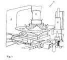
- FIG. 1shows a device 10 according to the invention, which holds the container bottom 30, in particular the cap 22, in a clamping means 12, so that a pressing tool 14 is used to deform the blank to the cap 22.
- the clamping means 12can be designed in various ways, it is essential that the clamping means 12, the dome 22 rotatably holds in a clamped position.
- the pressing tool 14allows, as Figure 1 shows, in addition to the determination of the dome 22, a rotation within the tools of Einspannstoffs 12. By forming by means of pressing tool 14 receives the blank, in particular the cap 22, the curvature radius r wi .
- FIG. 2essentially shows a heat supply device 18 for forming the brim 20 on the shaped dome 22, as described in FIG. 1.
- the heat supply device 18has a stator element 18A, a base element 18B, a media connection 18E and a burner 18F, which can pass through first fastening element 18C adjustable in its length and is arranged adjustable by a second fastening element 18D in its height and its angle.
- the heat supply device 18, in particular the burner 18Facts on the transition region 32 between the rim 20 and the cap 22, in the embodiment of an outer side 38 of the container bottom 30th
- FIG. 3shows the device 10, in particular a forming tool 16, which is designed in the form of a flaring bulb 42 and acts on the container bottom 30 from an inner side 36.
- the forming tool 16forms at least one crimping roller 24 opposite the crimping bulb 42, which guides and holds the container base 30 in the region of the brim to be formed.
- FIG. 3shows, in addition to the crimping roller 24, two pressure rollers 24a which stabilize the workpiece.
- the container bottom 30rotates in the direction of rotation 46.
- the device 10has a rotation table 40.
- the rotary table 40is shown in FIG. 4 and essentially has a support element 28 and a hold-down 26.
- the container bottom 30is in the forming tool 16 is rotationally moved on the rotary table 40 and in the area of the flaring bulb 42 and the rollers 24 (not visible in Figure 4).
- the brim 20is formed with simultaneous heat supply in the transition region 32, starting from the predetermined diameter d k of the calotte 22 with a predetermined radius r ki .
- FIG. 4shows this process of forming the brim 20, wherein the heat supply devices 18 are arranged symmetrically with respect to the crimping bulb 42 and the dowel rolls 24.
- the heat supply devices 18are arranged so that a heat supply via the burner 18 F is achieved exactly in the transition region 32 between the rim 20 and dome 22.
- the heat supply device 18acts from the outside 38 on the cap 22 and the brim 20 in the transition region 32, wherein also a supply of heat from the inside 36 and on both sides inside 36 and outside 38 is feasible.
- a stress relaxationis achieved during the formation of the rim 20 in the transition region 32 at the same time.
- a control unit 48with a control system for controlling the entire device 10, consisting from the spinning tool 14 and the forming tool 16, available.
- the control unit and the control system 48can also be used to control the heat supply device 18 (not shown). Another possibility is to set the temperature only over time.
- FIG. 5shows the container bottom 30 produced, in particular a basket bottom, after the return of the hold-down 26 of the forming tool 16.
- the support element 28is designed to be height adjustable.
- the forming tools 18are also for removing the container bottom 30 easily over rollers 44 movable, as Figure 5 shows.
- the method and the deviceare particularly suitable for the production of dished bottoms and basket sheet aluminum.
- the production of larger container bottomsusually results in decreasing radii r ki of the rim 20 to make the cap 22 and brim 20 separately and later - especially by welded joints - are reassembled. This procedure is particularly because stresses in a one-piece production can usually be avoided insufficient.
- the new method and the new associated devicenow make it possible to produce container bottoms 30 in one piece with heat supply in the transition region 32 and to achieve stress relaxation, in particular even if a decreasing radius r ki is to be formed into a particularly pronounced brim 22.
Landscapes
- Engineering & Computer Science (AREA)
- Mechanical Engineering (AREA)
- Shaping Metal By Deep-Drawing, Or The Like (AREA)
- Processing And Handling Of Plastics And Other Materials For Molding In General (AREA)
- Encapsulation Of And Coatings For Semiconductor Or Solid State Devices (AREA)
Abstract
Description
Translated fromGermanDie Erfindung betrifft ein Verfahren und eine Vorrichtung zum Metalldrücken eines Rohlings, aus Aluminium, zu einem gewölbten Formteil.The invention relates to a method and a device for metal pressing a blank, made of aluminum, to a curved molding.
Beim Metalldrücken wird ein als Blechronde oder Vorform vorliegender Rohling in Drehung versetzt und durch ein herangeführtes und vorgeschobenes Drückwerkzeug in das gewünschte, rotationssymmetrische Formteil gebracht. Ein Überblick über bekannte Drückverfahren ist in "Blech-Rohre-Profile" 28 (1981) 11, Seiten 514 - 517 entnehmbar. Bei den bekannten Drückverfahren wird der Rohling mittig in einem Druckfutter festgespannt, dessen äußere Kontur der Innenkontur des gewünschten Formteiles entspricht. Das Drückwerkzeug in Form einer Drückrolle folgt hingegen der Außenkontur des gewünschten Formteiles, so dass der Rohling zwischen der Drückrolle und dem Drückfutter geformt werden kann. Bei modernen Drückvorrichtungen wird die Drückrolle entweder über Kopierschablonen oder über eine NC-Steuerung bewegungsgesteuert.During metal pressing, a blank present as a sheet metal blank or preform is set in rotation and brought into the desired, rotationally symmetrical molded part by an introduced and advanced pressing tool. An overview of known pressing method is in "sheet-tube profiles" 28 (1981) 11, pages 514-517 can be removed. In the known spinning method, the blank is clamped centrally in a pressure chuck whose outer contour corresponds to the inner contour of the desired molded part. The spinning tool in the form of a spinning roller, however, follows the outer contour of the desired molded part, so that the blank between the spinning roller and the spinning chuck can be formed. In modern press devices, the spinning roller is motion-controlled either via copy templates or via an NC control.
In der Praxis besonders gebräuchliche Formteile sind Behälterböden von Druckbehältem mit zylindrischem Mantel. Nach dem Grad der Wölbung der Kalotte von Behälterböden unterscheidet man Klöpperböden, Korbbogenböden, Halbkugelböden sowie Tellerböden und ebene Böden. Mit abnehmender Wölbung beziehungsweise mit zunehmendem Wölbungsradius vereinfacht sich die Herstellung, so dass insbesondere Klöpperböden und Korbbogenböden aus einem einteiligen Rohling hergestellt werden. (Vgl. DIN 28011 und 28013)In practice, especially common moldings are container bottoms of Druckbehältem with cylindrical jacket. According to the degree of curvature of the dome of container bottoms, one distinguishes dished bottoms, basket bottom sheets, hemispherical bottoms and plate bottoms and even bottoms. With decreasing curvature or with increasing radius of curvature, the production is simplified, so that in particular dished bottoms and baskets floors are made of a one-piece blank. (See DIN 28011 and 28013)
Als allgemein bekannt gelten die Verfahren, bei denen ein Rohling, insbesondere ein Blech, innerhalb einer ersten Formgebungsstufe auf einen definierten Gesamtradius umgeformt wird und anschließend im äußeren Bereich des Bleches eine Umformung mit einem besonders starken Radius vorgenommen wird. Die während dieser formgebenden Umformungsprozesse entstehenden Spannungen werden durch anschließendes Glühen bei zirka 300 - 350 °C beseitigt.The processes in which a blank, in particular a metal sheet, is shaped to a defined total radius within a first shaping stage and then a forming with a particularly strong radius is then carried out in the outer region of the metal sheet. The resulting during this shaping forming processes stresses are removed by subsequent annealing at about 300 - 350 ° C.
Aus der Druckschrift DE 35 34 796 A1 sind ein Verfahren sowie eine Vorrichtung zur Formgebung von Blechen und Tafeln bekannt. Grundsätzlich wird hierbei eine Einspannung der zu verformenden Werkstücke vorgenommen, so dass sich eine elastische Umformung ergibt. Anschließend wird in einer oberflächennahen Schicht des unter elastischer Spannung stehenden Werkstückes die Umformenergie mittels elektrisch induzierter Wärme eingebracht, so dass das Material unter dem Einfluss der elastischen Spannung innerhalb dieser Schicht zum Fließen kommt, indem durch Temperaturerhöhung der Umformwiderstand überwunden wird. Auf diese Weise lassen sich richtungsunabhängige Verformungen erheblichen Ausmaßes erzielen, ohne dass es dabei zu Spuren bei Einspannung, wie beispielsweise beim Streckziehen, kommt, denn die für die Einspannung vorgesehenen Mittel sind Stützen, die praktisch ohne Einspannflächen am Werkstück angreifen. Diese Druckschrift repräsentiert lediglich den allgemeinen Stand der Technik, wobei das Einbringen einer Wärmemenge lediglich zur Herabsetzung der aufzubringenden Verformungsenergie dienen soll.From the document DE 35 34 796 A1 discloses a method and an apparatus for shaping of sheets and panels are known. Basically, a clamping of the workpieces to be deformed is made, so that an elastic deformation results. Subsequently, the forming energy is introduced by means of electrically induced heat in a near-surface layer of the workpiece under elastic tension, so that the material under the influence of the elastic stress within this layer to flow, is overcome by increasing the temperature Umformwiderstand. In this way, direction-independent deformations can be achieved to a considerable extent, without resulting in traces during clamping, such as during ironing, for the funds provided for the clamping means are supports that attack virtually without clamping surfaces on the workpiece. This document merely represents the general state of the art, wherein the introduction of a quantity of heat is only intended to reduce the deformation energy to be applied.
Ferner ist aus der DE 100 47 491 A1 ein Verfahren zum Umformen von Strukturen aus Aluminium-Legierungen bekannt, welches ein umzuformendes Bauteil durch elastisches Formen in eine vorgegebene Kontur unter externer Krafteinwirkung und Erwärmen des elastisch geformten Bauteils auf eine Temperatur größer als die für eine Kriechumformung und Spannungsrelaxation der Legierung erforderlichen Temperatur bringt, so dass das Bauteil unter Beibehaltung der Kontur umgeformt wird. Dieses Verfahren ist beispielhaft für Verfahren, bei denen zunächst in einem ersten Formgebungsschritt Kräfte einwirken, um eine vorgegebene Kontur eines Bauteils zu erreichen und in einem zweiten Schritt eine Wärmebehandlung erfolgt, durch die entstandene Spannungen anschließend beseitigt werden.
Diese zweistufige Durchführung des Formgebungsverfahrens ist sehr aufwendig und erfordert die Erwärmung des gesamten Bauteils zur Beseitigung der vorhandenen Spannungen.Furthermore, from DE 100 47 491 A1 discloses a method for forming structures of aluminum alloys is known, which is a reshaped component by elastic molding in a predetermined contour under external force and heating the elastically-shaped component to a temperature greater than that for creep and stress relaxation of the alloy brings necessary temperature, so that the component while maintaining the Contour is reshaped. This method is exemplary for methods in which initially act in a first shaping step forces to achieve a predetermined contour of a component and in a second step, a heat treatment takes place, are then eliminated by the resulting stresses.
This two-stage implementation of the shaping process is very complicated and requires the heating of the entire component to eliminate the existing stresses.
Aus dem Stand der Technik geht ein weiteres Verfahren hervor, bei dem gemäß der Druckschrift DE 40 16 097 A1 ein Rohling durch Metalldrücken zu einem gewölbten Formteil umgeformt wird, indem der Rohling umfangseitig eingespannt und in einen Freiraum hineingewölbt wird. Innerhalb dieses Verfahrens wird bereits im ersten Formgebungsschritt eine erhöhte Arbeitstemperatur beim Metalldrücken durch ein zweistufiges Erwärmen des Rohlings eingesetzt, wobei im Wesentlichen der gesamte Rohling auf eine erste, unter Arbeitstemperatur liegende Temperatur gebracht und gehalten wird und nur Teilbereiche des Rohlings vor dem Drücken auf Arbeitstemperatur gebracht werden. Nachteilig hierbei ist, dass das Verfahren ebenfalls notwendigerweise den kompletten Rohling zunächst auf eine Arbeitstemperatur unterhalb der späteren beim Metalldrücken in Teilbereichen des Rohlings erforderlichen Arbeitstemperatur gebracht werden muss. Zudem benötigt das Verfahren eine Vorrichtung, bei der zum Metalldrücken in Abhängigkeit der gewünschten Temperaturen eine zweistufige Aufheizeinrichtung vorgesehen ist, um die zweistufige Formgebung mit unterschiedlichen Arbeitstemperaturen durchführen zu können.From the prior art, a further method is shown in which according to the
Die US-A-2 300 527 offenbart eine Vorrichtung gemäß dem Oberbegriff des Anspruchs 7, die zur Herstellung eines Behälter bodens aus Aluminium geeignet ist, sowie ein Verfahren zum Metalldrücken eines Rohlings zu einem gewölbten Formteil. Der Rohling wird umfangsseitig eingespannt und in einen Freiraum wird eine Kalotte auf einen vorgebbaren Wölbungsradius hineingewölbt, wobei die Kalotte anschließend rotierend niedergehalten wird, wobei unter gleichzeitiger Wärmezufuhr in einem, von einem vorgebbaren Durchmesser der Kalotte bestimmten Übergangsbereich eine Krempe mit einem vorgebbaren Radius ausgeformt wird.US-A-2 300 527 discloses an apparatus according to the preamble of claim 7 which is suitable for producing a container bottom made of aluminum, and a method for metal-pressing a blank into a curved molding. The blank is clamped circumferentially and in a space a dome is arched to a predeterminable radius of curvature, the dome then held down rotating is, with the simultaneous application of heat in a, determined by a predetermined diameter of the dome transition region, a brim with a predetermined radius is formed.
Die Umformung eines Radius unter gleichzeitiger örtlicher Wärmezufuhr ist im Bereich der Herstellung derartiger gewölbter Formteile bekannt, wobei zur Bildung der Radien verschiedene Mittel eingesetzt werden.The transformation of a radius with simultaneous local heat is known in the field of producing such curved moldings, wherein different means are used to form the radii.
Der Erfindung liegt somit die Aufgabe zugrunde, ein Verfahren und eine Vorrichtung vorzuschlagen, welche kostengünstig ein maßgenaues Umformen von Formteilen, insbesondere von Behälterböden, erlaubt, wobei insbesondere in den Bereichen, bei denen durch den Umformvorgang große Spannungen auftreten, können Spannungen bereits während des Umformvorganges vermieden werden oder nur in sehr geringem Maß auftreten.The invention is therefore based on the object to provide a method and an apparatus which cost dimensionally accurate forming of moldings, in particular container bottoms allowed, in particular in the areas where high stresses occur by the forming process, stresses already during the forming process be avoided or occur only to a very limited extent.
Diese Aufgabe wird durch ein Verfahren und eine Vorrichtung gemäß Anspruch 1 und Anspruch 7 gelöst.This object is achieved by a method and an apparatus according to claim 1 and claim 7.
Dadurch, dass eine Kalotte mit einem vorgebbaren Wölbungsradius rotierend niedergehalten wird und unter gleichzeitiger Wärmezufuhr in einem, von einem vorgebbaren Durchmesser der Kalotte bestimmten Übergangsbereich eine Krempe mit einem vorgebbaren Radius ausgeformt wird, wird die Bildung von Spannungen im Übergangsbereich zwischen Kalotte und Krempe von vorneherein vermieden, so dass auf ein anschließendes Glühen generell verzichtet werden kann. In vorteilhafter Weise ist dadurch die Kalotte nur im Übergangsbereich zum Abbau der Spannungen zu erwärmen, so dass auf eine Erwärmung des gesamten Bauteils verzichtet werden kann.Characterized in that a dome with a predetermined radius of curvature is held down in rotation and formed with simultaneous heat input in a predetermined by a predetermined diameter of the dome transition area a brim with a predetermined radius, the formation of stresses in the transition region between the dome and brim is avoided from the outset , so that can be dispensed with a subsequent annealing in general. Advantageously, the calotte is thereby only to be heated in the transition region for reducing the stresses, so that heating of the entire component can be dispensed with.
Ferner ist dadurch, dass eine Rotationseinrichtung, auf der die rotierende Kalotte durch mindestens eine stationäre Wärmezuführungseinrichtung und ein stationäres Umformwerkzeug zumindest im Übergangsbereich des vorgebbaren Durchmessers erwärmbar und eine Krempe auf einen vorgebbaren Radius ausformbar ist, eine Vorrichtung ausgebildet, die es in vorteilhafter Weise erlaubt, die Kalotte genau im vorgegebenen Übergangsbereich mittels der Wärmezuführungseinrichtung umzuformen und durch ein angeordnetes stationäres Umformwerkzeug die Krempe spannungsfrei auf einen vorgebbaren Radius auszuformen.Furthermore, by virtue of the fact that a rotation device on which the rotating dome can be heated by at least one stationary heat supply device and a stationary forming tool, at least in the transition region of the predeterminable diameter, and a brim can be shaped to a predefinable radius, a device is formed which advantageously permits to form the calotte exactly in the predetermined transitional area by means of the heat supply device and by an arranged stationary forming tool to form the brim stress-free to a predeterminable radius.
Aus dem erfindungsgemäßen Verfahren und der zugehörigen Vorrichtung entstehen Formteile, insbesondere Behälterböden, wie Klöpperböden, Korbbogenböden oder auch Halbkugelböden, die sich dadurch auszeichnen, dass sie eine Kalotte und eine Krempe umfassen, wobei die Kalotte einen Wölbungsradius und die Krempe einen gegenüber dem Wölbungsradius reduzierten Radius und einen auf einem vorgebbaren Durchmesser ausgebildeten Übergangsbereich zwischen Kalotte und Krempe aufweisen, sowie durch eine während der Herstellung der Krempe in dem Übergangsbereich durchgeführte Wärmebehandlung spannungsarm oder im Idealfall spannungsfrei ausgebildet sind.Moldings, in particular container bottoms, such as dished ends, baskets or hemispherical bottoms, which are characterized in that they comprise a dome and a brim, the dome has a radius of curvature and the brim a radius reduced relative to the dome radius and have a transition region between the calotte and the brim formed on a predeterminable diameter, as well as being stress-relieved or ideally tension-free by a heat treatment carried out during the production of the brim in the transition region.
Der Übergangsbereich zwischen dem vorgebbaren Wölbungsradius der Kalotte und dem Bereich des auszuformenden Radius der Krempe wird ausgebildet und erwärmt.The transition region between the predeterminable curvature radius of the calotte and the region of the radius of the rim to be formed is formed and heated.
Im Übergangsbereich wird dazu die mindestens eine Wärmezuführungseinrichtung in Rotationsrichtung vor dem Umformwerkzeug positioniert. Vorzugsweise werden mehrere Wärmezuführungseinrichtungen am Übergangsbereich zwischen Kalotte und Krempe angeordnet, die in einer ersten Ausführungsvariante gegenüberliegend beziehungsweise in einer zweiten Ausführungsvariante symmetrisch an der Kalotte angeordnet werden.In the transition region, the at least one heat supply device is positioned in the direction of rotation in front of the forming tool for this purpose. Preferably, a plurality of heat supply devices are arranged at the transition region between the dome and the brim, which are arranged symmetrically on the dome in a first embodiment variant or in a second embodiment variant symmetrically.
Bevorzugt ist eine Anordnung der Wärmezuführungseinrichtung von einer Außenseite der Kalotte, wobei eine Anordnung von der Innenseite beziehungsweise von der Außen- und Innenseite und somit eine einseitige beziehungsweise zweiseitige Wirkung auf den Übergangsbereich erzielbar ist.An arrangement of the heat supply device from an outer side of the calotte is preferred, wherein an arrangement of the inner side or of the outer and inner side and thus a one-sided or two-sided effect on the transition region can be achieved.
Erfindungsgemäß wird durch die angeordnete Wärmezuführungseinrichtung der Übergangsbereich gleichmäßig erwärmt, wobei eine gewünschte Umformtemperatur für das Formteil auswählbar ist. Die Erwärmung des Formteils bei der vorgegebenen Temperatur führt unter Spannungsrelaxation zu einer plastischen Umformung der Kalotte im Übergangsbereich unter Ausformung der Krempe.According to the transition region is uniformly heated by the arranged heat supply means, wherein a desired forming temperature for the molding is selectable. The heating of the molding at the predetermined temperature leads under stress relaxation to a plastic deformation of the dome in the transition region under formation of the brim.
Ferner bevorzugt ist, dass die vorgebbare Temperatur im Übergangsbereich zwischen Kalotte und Krempe durch Steuerung der Wärmezuführungseinrichtung und/oder Beabstandung der Wärmezuführungseinrichtung zur Oberfläche der Kalotte beziehungsweise der Krempe eingestellt wird. Schließlich wird durch Steuerung und/oder Beabstandung der Wärmezuführungseinrichtung eine Wirkfläche der Wärmezuführungseinrichtung in Abhängigkeit der gewünschten zu erwärmenden Fläche des Übergangsbereiches eingestellt.Furthermore, it is preferred that the predeterminable temperature in the transitional area between the dome and the brim be adjusted by controlling the heat supply device and / or spacing the heat supply device to the surface of the dome or the brim. Finally, by controlling and / or spacing the heat supply device, an active surface of the heat supply device is set as a function of the desired area of the transition region to be heated.
Die erfindungsgemäße Vorrichtung zur Durchführung des Verfahrens umfasst ein Drückwerkzeug zum Metalldrücken eines Rohlings, ein Einspannmittel zum Einspannen des Rohlings und eine Rotationseinrichtung, auf der die rotierende Kalotte durch mindestens eine stationäre Wärmezuführungseinrichtung und ein stationäres Umformwerkzeug ausformbar ist.The device according to the invention for carrying out the method comprises a pressing tool for metal pressing a blank, a clamping means for clamping the blank and a rotation device on which the rotating Cap is formed by at least one stationary heat supply device and a stationary forming tool.
In bevorzugter Ausgestaltung weist die Rotationseinrichtung einen Rotationstisch mit einem Auflageelement und einen Niederhalter auf. Der Niederhalter greift vorzugsweise im Mittelpunkt an einer Innenseite des Formteils, insbesondere der Kalotte, an. Das Drückwerkzeug und das stationäre Umformwerkzeug sind in einer gemeinsamen Vorrichtung oder in getrennten Vorrichtungen ausführbar.In a preferred embodiment, the rotation device on a rotary table with a support element and a hold-down. The hold-down device preferably engages in the center on an inner side of the molded part, in particular of the calotte. The spinning tool and the stationary forming tool are executable in a common device or in separate devices.
Das Drückwerkzeug greift an der Innenseite der Kalotte an, wobei das stationäre Umformwerkzeug in bevorzugter Ausgestaltung der Erfindung eine Bördelbirne ist, die ebenfalls an der Innenseite der Kalotte und eine Bördelrolle, die an einer Außenseite der Kalotte angreift, aufweist.The pressing tool engages on the inside of the dome, wherein the stationary forming tool in a preferred embodiment of the invention is a flaring pear, which also has on the inside of the dome and a crimping roller which acts on an outer side of the dome.
Die Kalotte ist auf dem vorgebbaren Durchmesser und dem ausgebildeten Übergangsbereich durch die Wärmezuführungseinrichtung derart erwärmbar dass die Krempe auf einem vorgebbaren Radius durch plastische Materialumformung ausbildbar ist.The calotte can be heated on the predeterminable diameter and the formed transition region by the heat supply device such that the brim can be formed on a predeterminable radius by plastic material deformation.
Die Wärmezuführungseinrichtung weist ein Ständerelement, ein Basiselement, ein erstes und zweites Befestigungselement und einen Medienanschluss sowie einen Brenner auf. Das erste und zweite Befestigungselement dienen zur Einstellung eines Winkels und eines Abstandes des Brenners gegenüber der Kalotte beziehungsweise zur Verstellung einer Höhe des Brenners gegenüber der Kalotte.The heat supply device has a stator element, a base element, a first and a second fastening element and a media connection and a burner. The first and second fastener serve to adjust an angle and a distance of the burner relative to the dome or for adjusting a height of the burner relative to the dome.
In bevorzugter Ausgestaltung ist der Brenner durch die erste und/oder zweite Einrichtung so anordbar, dass die Brennerflamme rechtwinklig auf den Übergangsbereich trifft, wobei der Brenner jederzeit vor und während des Verfahrens nachjustierbar, also auch in anderen Winkeln zur zu verformenden Oberfläche im Übergangsbereich einstellbar istIn a preferred embodiment, the burner can be arranged by the first and / or second device such that the burner flame strikes the transition region at right angles, wherein the burner can be readjusted at any time before and during the process, ie also at other angles to the surface to be deformed in the transition region
Durch das Verfahren, bei dem das Umformen des Formteiles im Übergangsbereich und seine Erwärmung gleichzeitig durchgeführt werden, wird in vorteilhafter Weise bei der für das umzuformende Material geeigneten Temperatur, die bei nur zirka 120 °C liegt und in jedem Fall unterhalb einer Glühtemperatur liegt, die Bildung von Spannungen im stark umzuformenden Übergangsbereich zwischen Kalotte und Krempe von vornherein vermieden.By the method in which the forming of the molding in the transition region and its heating are carried out simultaneously, is advantageously at the suitable temperature for the material to be formed, which is only about 120 ° C and in any case below an annealing temperature, the Forming of stresses in the strongly transforming transition region between dome and brim from the outset avoided.
Durch das Einbringen der Wärme auf diesem relativ niedrigen Niveau, beispielsweise mit zwei gegenüberliegenden Wärmequellen oder mit mehreren symmetrisch angeordneten Wärmequellen, wird bei Rotation des Behälterbodens der Bördelbereich, also der Bereich zwischen Kalotte und Krempe, sehr gleichmäßig erwärmt, so dass optimale Materialeigenschaften für eine Umformung und nach dem Umformprozess Spannungsfreiheit erreicht werden.By introducing the heat at this relatively low level, for example, with two opposing heat sources or with a plurality of symmetrically arranged heat sources, during rotation of the container bottom of the crimping, ie the area between the dome and brim, heated very evenly, so that optimum material properties for forming and after the forming process voltage freedom can be achieved.
Durch Anordnung eines relativ breiten Brenners beziehungsweise einer relativ großflächigen Erwärmung, wird dafür gesorgt, dass über den mechanischen Verformungsbereich das gesamte Material gleichmäßig erwärmt wird. Dadurch können in vorteilhafter Weise die einzubringenden Umformkräfte reduziert werden.By arranging a relatively wide burner or a relatively large-scale heating, it is ensured that over the mechanical deformation range, the entire material is heated evenly. As a result, the forming forces to be introduced can be reduced in an advantageous manner.
Ferner besteht die Möglichkeit, eine wesentlich größere Maßgenauigkeit als bei den bisher bekannten Verfahren zu erreichen, so dass in vorteilhafter Weise keine Nacharbeiten nötig sind. Bei dem bekannten Glühen eines bereits verformten Behälterbodens, beispielsweise eines Korbbogenbodens, muss der Boden im Hinblick auf den definierten Gesamtradius und den Randradius nachgearbeitet werden. Durch das erfindungsgemäße Verfahren können diese Verfahrensschritte ersatzlos entfallen.It is also possible to achieve a much greater dimensional accuracy than in the previously known methods, so that advantageously no reworking is necessary. In the known annealing of an already deformed container bottom, for example a basket bottom, the bottom must be reworked with regard to the defined total radius and the edge radius. The inventive method, these steps can be omitted without replacement.
Weitere bevorzugte Ausgestaltung der Erfindung ergeben sich aus den in den weiteren Ansprüchen genannten Merkmalen.Further preferred embodiment of the invention will become apparent from the features mentioned in the other claims.
Die Erfindung wird nachfolgend in einem Ausführungsbeispiel anhand der zugehörigen Zeichnungen näher erläutert. Es zeigen:
- Figur 1
- eine Vorrichtung zum Metalldrücken als Drückwerkzeug eines Formteiles mit zugehörigem Einspannmittel;
- Figur 2
- das Formteil und eine Wärmezuführungseinrichtung;
- Figur 3
- das Formteil und eine Vorrichtung zum Umformen als ein Umformwerkzeug;
- Figur 4
- das Umformwerkzeug mit angeordneten Wärmezuführungseinrichtungen während der Umformung;
- Figur 5
- das Umformwerkzeug mit Wärmezuführungseinrichtung nach der Umformung und
- Figur 6
- eine schematische Darstellung des Formteiles, insbesondere ein Korbbodenbogen.
- FIG. 1
- a device for metal pressing as a pressing tool of a molded part with associated clamping means;
- FIG. 2
- the molded part and a heat supply device;
- FIG. 3
- the molding and a device for forming as a forming tool;
- FIG. 4
- the forming tool with arranged heat supply means during the forming;
- FIG. 5
- the forming tool with heat supply device after forming and
- FIG. 6
- a schematic representation of the molded part, in particular a basket bottom sheet.
Zunächst zeigt Figur 6 schematisch einen Behälterboden 30, insbesondere einen Korbbogenboden. Der Behälterboden 30 weist eine Kalotte 22 und eine Krempe 20 auf. Die Kalotte 22 weist einen Wölbungsradius rwi und die Krempe 20 einen Radius rki auf. Die Kalotte 22 selbst wird durch den Durchmesser dk und die Krempe 20 und die Kalotte 22 durch einen Nenndurchmesser da bestimmt. Figur 6 zeigt einen Übergangsbereich 32 zwischen Krempe 20 und Kalotte 22.First, Figure 6 shows schematically a container bottom 30, in particular a basket bottom. The container bottom 30 has a
Die Herstellung eines Behälterbodens 30 gemäß Figur 6, insbesondere mit Übergangsbereichen 32, zwischen der Kalotte 22 und der Krempe 20, die bei der Herstellung von Klöpperböden oder Korbbogenböden ausgebildet werden müssen, wird in einem Ausführungsbeispiel in den Figuren 1 bis 5 weiter erläutert.The production of a container bottom 30 according to FIG. 6, in particular with
Figur 1 zeigt eine erfindungsgemäße Vorrichtung 10, die den Behälterboden 30, insbesondere die Kalotte 22, in einem Einspannmittel 12 festhält, so dass ein Drückwerkzeug 14 zu einer Verformung des Rohlings zur Kalotte 22 eingesetzt wird. Das Einspannmittel 12 kann verschiedenartig ausgeführt sein, wesentlich ist, dass das Einspannmittel 12 die Kalotte 22 rotierend in einer eingespannten Lage festhält. Das Drückwerkzeug 14 erlaubt, wie Figur 1 zeigt, neben der Festlegung der Kalotte 22 eine Rotation innerhalb der Werkzeuge des Einspannmittels 12. Durch das Umformen mittels Drückwerkzeug 14 erhält der Rohling, insbesondere die Kalotte 22, den Wölbungsradius rwi.FIG. 1 shows a
Figur 2 zeigt im Wesentlichen eine Wärmezuführungseinrichtung 18 zur Ausbildung der Krempe 20 an der - wie in Figur 1 beschriebenen - geformten Kalotte 22. Die Wärmezuführungseinrichtung 18 weist ein Ständerelement 18A, ein Basiselement 18B, einen Medienanschluss 18E und einen Brenner 18F auf, der durch ein erstes Befestigungselement 18C in seiner Länge verstellbar und durch ein zweites Befestigungselement 18D in seiner Höhe und seinem Winkel verstellbar angeordnet ist. Die Wärmezuführungseinrichtung 18, insbesondere der Brenner 18F, wirkt auf den Übergangsbereich 32 zwischen Krempe 20 und Kalotte 22, im Ausführungsbeispiel von einer Außenseite 38 des Behälterbodens 30.FIG. 2 essentially shows a
Figur 3 zeigt die Vorrichtung 10, insbesondere ein Umformwerkzeug 16, welches in Form einer Bördelbirne 42 ausgeführt ist und von einer Innenseite 36 auf den Behälterboden 30 einwirkt. Das Umformwerkzeug 16 bildet der Bördelbirne 42 gegenüberliegend mindestens eine Bördelrolle 24 aus, die den Behälterboden 30 im Bereich der auszubildenden Krempe 20 führt und festhält. Figur 3 zeigt neben der Bördelrolle 24 zwei Druckrollen 24a, die das Werkstück stabilisieren. Bei der Umformung der Krempe 20 an die Kalotte 22 rotiert der Behälterboden 30 in Rotationsrichtung 46. Zur Durchführung der Rotation weist die Vorrichtung 10 einen Rotationstisch 40 auf.FIG. 3 shows the
Der Rotationstisch 40 ist in Figur 4 dargestellt und weist im Wesentlichen ein Auflageelement 28 und einen Niederhalter 26 auf. Der Behälterboden 30 wird in dem Umformwerkzeug 16 rotierend auf dem Rotationstisch 40 bewegt und im Bereich der Bördelbirne 42 und der Rollen 24 (in Figur 4 nicht sichtbar) umgeformt.The rotary table 40 is shown in FIG. 4 and essentially has a
Erfindungsgemäß wird die Krempe 20 unter gleichzeitiger Wärmezufuhr in dem Übergangsbereich 32 ausgehend vom vorgegebenen Durchmesser dk der Kalotte 22 mit einem vorgegebenen Radius rki ausgeformt.According to the invention, the
Figur 4 zeigt diesen Vorgang der Ausformung der Krempe 20, wobei die Wärmezuführungseinrichtungen 18 symmetrisch bezüglich der Bördelbirne 42 und der Bödelrollen 24 angeordnet sind. Die Wärmezuführungseinrichtungen 18 sind so angeordnet, dass eine Wärmezufuhr über den Brenner 18F genau im Übergangsbereich 32 zwischen Krempe 20 und Kalotte 22 erreicht wird. Im Ausführungsbeispiel wirkt die Wärmezuführungseinrichtung 18 von der Außenseite 38 auf die Kalotte 22 beziehungsweise die Krempe 20 im Übergangsbereich 32, wobei auch eine Zuführung der Wärme von der Innenseite 36 beziehungsweise beidseitig Innenseite 36 und Außenseite 38 durchführbar ist. Durch die Wärmezuführung wird während der Ausformung der Krempe 20 im Übergangsbereich 32 gleichzeitig eine Spannungsrelaxation erreicht.FIG. 4 shows this process of forming the
Zur Durchführung des Verfahrens - Metalldrücken des Rohlings - durch das Drückwerkzeug 14 und - Umformen der Kalotte 22 - unter Ausformung der Krempe 20 mit dem Umformwerkzeug 16 steht, wie Figur 4 zeigt, ein Steuergerät 48 mit einem Steuersystem zur Ansteuerung der gesamten Vorrichtung 10, bestehend aus dem Drückwerkzeug 14 und dem Umformwerkzeug 16, zur Verfügung. Das Steuergerät und das Steuersystem 48 können auch zur Ansteuerung der Wärmezuführungseinrichtung 18 (nicht dargestellt) eingesetzt werden. Eine andere Möglichkeit besteht darin, die Temperatur nur über die Zeit einzustellen.For carrying out the method - metal pressing of the blank - by the
Figur 5 zeigt den hergestellten Behälterboden 30, insbesondere einen Korbbogenboden, nach Rückführung des Niederhalters 26 des Umformwerkzeuges 16.FIG. 5 shows the container bottom 30 produced, in particular a basket bottom, after the return of the hold-down 26 of the forming
Durch Vergleich von Figur 5 und Figur 4 ist erkennbar, dass das Auflageelement 28 höhenverstellbar ausgeführt ist.By comparing Figure 5 and Figure 4 it can be seen that the
Die Umformwerkzeuge 18 sind ferner zur Entnahme des Behälterbodens 30 problemlos über Rollen 44 verfahrbar, wie Figur 5 zeigt.The forming
Das Verfahren und die Vorrichtung eignen sich im besonderen Maße für die Herstellung von Klöpperböden und Korbbogenböden aus Aluminium. Die Herstellung größerer Behälterböden führt zumeist bei abnehmenden Radien rki der Krempe 20 dazu, dass Kalotte 22 und Krempe 20 getrennt hergestellt und später - insbesondere durch Schweißverbindungen - wieder zusammengefügt werden. Diese Vorgehensweise erfolgt insbesondere deswegen, weil Spannungen bei einer einteiligen Herstellung zumeist unzureichend vermieden werden können.The method and the device are particularly suitable for the production of dished bottoms and basket sheet aluminum. The production of larger container bottoms usually results in decreasing radii rki of the
Das neue Verfahren und die neue zugehörige Vorrichtung erlauben nunmehr, Behälterböden 30 einteilig unter Wärmezufuhr im Übergangsbereich 32 herzustellen und eine Spannungsrelaxation zu erreichen, insbesondere auch dann, wenn ein abnehmender Radius rki zu einer besonders stark ausgeformten Krempe 22 umgeformt werden soll.The new method and the new associated device now make it possible to produce
- 1010
- Vorrichtungcontraption
- 1212
- Einspannmittelchuck
- 1414
- Drückwerkzeugspinning tool
- 1616
- Umformwerkzeug (Bördelrolle/Bördelbirne)Forming tool (crimping roller / flare bulb)
- 1818
- WärmezuführungseinrichtungHeat supply facility
- 18A18A
- Ständerelementstand element
- 18B18B
- Basiselementbase element
- 18C18C
- erstes Befestigungselement (Winkel, Länge)first fastening element (angle, length)
- 18D18D
- zweites Befestigungselement (Höhe)second fastening element (height)
- 18E18E
- Medienanschlussmedia connection
- 18F18F
- Brennerburner
- 2020
- Krempebrim
- 2222
- Kalottedome
- 2424
- Bördelrolleflanging
- 24a24a
- Druckrollepressure roller
- 2626
- NiederhalterStripper plate
- 2828
- Auflageelementsupport element
- 3030
- Behälterbodencontainer bottom
- 3232
- ÜbergangsbereichTransition area
- 4646
- MittelpunktFocus
- 3636
- Innenseiteinside
- 3838
- Außenseiteoutside
- 4646
- Rotationstischrotary table
- 4242
- BördelbirneBördelbirne
- 4444
- Rollerole
- 4646
- Rotationsrichtungdirection of rotation
- 4848
- Steuersystem/SteuergerätControl system / control unit
- rwirwi
- Wölbungsradius KalotteBuckling radius calotte
- rkirki
- Radius KrempeRadius brim
- dkdk
- Durchmesser KalotteDiameter calotte
- dada
- NenndurchmesserNominal diameter
Claims (13)
- A procedure for the metal spinning of an aluminium blank into a curved formed part, i.e. into a receptacle base, in which the blank is clamped around its circumference and a calotte (22) is curved into a free space onto a prespecifiable curvature radius (rwi), whereby the calotte (22) is then held down while rotating, whereby while heat is simultaneously supplied in a transfer area (32) which is determined by a prespecifiable diameter (dk) of the calotte (22), a rim (20) with a prespecifiable radius (rki) is formed, wherebya) the transfer area (32) between the prespecifiable curvature radius (rwi) of the calotte (22) and the area of the radius (rki) to be formed of the rim (22) is formed and heatedb) at least one heat supply facility (18) is positioned in the transfer area (32) in the direction of rotation (46) in front of a deforming tool (16)c) the at least one heat supply facility (18) affects the transfer area (32) from one outer side (38) and/or one inner side (36) of the calotte (22)d) the at least one heat supply facility (18) heats the transfer area (32) evenlye) with a prespecifiable temperature below stress relaxation, a plastic de formation of the calotte (22) is conducted, with the rim (22) in the transfer area (32) being moulded, andf) the prespecifiable temperature is approx. 120°C.
- A procedure according to claim 1,characterized in that several heat supply facilities (18) are positioned on the transfer area (32) between the calotte (22) and the rim (22).
- A procedure according to claim 2,characterized in that the heat supply facilities (18) are positioned on the rotating calotte (22) opposite each other.
- A procedure according to either of claims 2 or 3,characterized in that the heat supply facilities (18) are positioned symmetrically on the rotating calotte (22).
- A procedure according to any of claims 1 to 4,characterized in that the prespecifiable temperature in the transfer area (32) between the calotte (22) and the rim (22) is set by controlling the at least one heat supply facility (18) and/or by adjusting the distance between the heat supply facility (18) and the surface of the calotte (22) or the rim (22).
- A procedure according to claim 5,characterized in that an active area of the heat supply facility (18) is set in dependence on the surface of the transfer area (32) to be heated.
- A device for the metal spinning of an aluminium blank into a curved formed part, i.e. into a receptacle base, which comprises at least one clamping appliance (12) to clamp the blank around its circumference and a movement-controlled spinning tool (14) with a curvature radius (rwi) for the production of a calotte by curving it into a free space, with one direction of rotation (40), on which the rotating calotte (22) can be heated by at least one stationary heat supply facility (18) and one stationary deforming tool (16), at least in the transfer area (32) of a prespecifiable diameter (dk), and a rim (20) can be moulded to a prespecifiable radius (rki),characterized in that the heat supply facility (18) comprises a stand element (18A), a base element (18B), a first and a second attachment element (18C, 18D) and one media connection (18E) as well as a burner (18F).
- A device according to claim 7,characterized in that the direction of rotation (46) comprises a spinning table (40) with a support element (28) and a holding-down clamp (26), whereby the support element (28) and the holding-down clamp (26) preferably engage in the central point (34) of the calotte (22).
- A device according to claim 8,characterized in that the stationary deforming tool (16) comprises a flanged bulb (42), which engages on one inner side (36) of the calotte (22) and a flanged roll (44), which engages on one outer side of the calotte (22).
- A device according to claim 7,characterized in that the first attachment element (18C) comprises a first facility for setting an angle and a distance of the burner (18F) opposite the calotte (22).
- A device according to claim 7,characterized in that the second attachment element (18D) comprises a second facility for adjusting a height of the burner (18F).
- A device according to any one of claims 7 to 11,characterized in that with the aid of the first and/or second facility, any arrangement, preferably a right-angled arrangement, of the burner (18F) opposite the transfer area (32) can be set in a manner which can be subsequently adjusted.
- A deice according to any one of claims 7 to 12,characterized in that the heat supply facility (18), in particular, the burner (18F), can be operated with a combustible material, such as gas or oil.
Applications Claiming Priority (2)
| Application Number | Priority Date | Filing Date | Title |
|---|---|---|---|
| DE10324366 | 2003-05-27 | ||
| DE10324366ADE10324366A1 (en) | 2003-05-27 | 2003-05-27 | Method and device for producing a molded part, and molded part, in particular a container base |
Publications (2)
| Publication Number | Publication Date |
|---|---|
| EP1481744A1 EP1481744A1 (en) | 2004-12-01 |
| EP1481744B1true EP1481744B1 (en) | 2006-10-18 |
Family
ID=32309087
Family Applications (1)
| Application Number | Title | Priority Date | Filing Date |
|---|---|---|---|
| EP04003037AExpired - LifetimeEP1481744B1 (en) | 2003-05-27 | 2004-02-11 | Process and apparatus for producing a shaped article |
Country Status (4)
| Country | Link |
|---|---|
| EP (1) | EP1481744B1 (en) |
| AT (1) | ATE342780T1 (en) |
| DE (3) | DE10324366A1 (en) |
| ES (1) | ES2274332T3 (en) |
Cited By (1)
| Publication number | Priority date | Publication date | Assignee | Title |
|---|---|---|---|---|
| CN102172701A (en)* | 2011-01-27 | 2011-09-07 | 温岭市旭日滚塑科技有限公司 | Fast spin forming process for rotomolding mould |
Families Citing this family (15)
| Publication number | Priority date | Publication date | Assignee | Title |
|---|---|---|---|---|
| JP4144637B2 (en) | 2005-12-26 | 2008-09-03 | セイコーエプソン株式会社 | Printing material container, substrate, printing apparatus, and method for preparing printing material container |
| CN101391372B (en)* | 2008-10-22 | 2010-06-02 | 中材科技(苏州)有限公司 | Gas cylinder dished head shaping technique |
| US10092941B2 (en) | 2012-08-10 | 2018-10-09 | Kawasaki Jukogyo Kabushiki Kaisha | Spinning forming apparatus and forming method |
| WO2014034140A1 (en)* | 2012-09-03 | 2014-03-06 | 川崎重工業株式会社 | Spin forming method and spin forming device |
| JP6077852B2 (en)* | 2012-12-18 | 2017-02-08 | 川崎重工業株式会社 | Spinning molding equipment |
| JP6291230B2 (en)* | 2013-11-29 | 2018-03-14 | 川崎重工業株式会社 | Spinning molding apparatus and spinning molding method |
| CN105583321A (en)* | 2015-12-23 | 2016-05-18 | 常州旷达威德机械有限公司 | Closing device for sealing head and closing method |
| CN105537356A (en)* | 2015-12-25 | 2016-05-04 | 中国航空工业集团公司北京航空制造工程研究所 | Induction heating spinning forming system and method |
| CN108161230B (en)* | 2018-01-30 | 2023-07-21 | 苏州德龙激光股份有限公司 | Device and method for processing spherical crown grid net in quasi-3D mode |
| DE102018220265A1 (en)* | 2018-11-26 | 2020-05-28 | Thyssenkrupp Ag | End floor |
| CN109622714A (en)* | 2019-01-23 | 2019-04-16 | 西安深瞳智控技术有限公司 | A kind of the head-shield rotary pressing moulding device and its manufacturing process of target seeker |
| CN112872140B (en)* | 2020-12-22 | 2022-11-29 | 池州赛唯特电子科技有限公司 | Automatic edge folding device for plastic shell of buzzer |
| CN113732150B (en)* | 2021-10-13 | 2024-03-15 | 广东科欣电气有限公司 | Clamping mechanism for spinning machine |
| CN116062441B (en)* | 2023-01-19 | 2024-08-13 | 广州红尚机械制造有限公司 | Head processing equipment |
| CN116786672B (en)* | 2023-08-24 | 2023-10-31 | 河南神州精工制造股份有限公司 | Spinning forming equipment for large-diameter melon petal seal head |
Family Cites Families (8)
| Publication number | Priority date | Publication date | Assignee | Title |
|---|---|---|---|---|
| FR597734A (en)* | 1925-01-29 | 1925-11-27 | Improvements in the manufacture of containers or parts of containers made of sheet aluminum or similar material | |
| US2300527A (en)* | 1940-04-20 | 1942-11-03 | Charles E Scheuring | Peripheral flange formation apparatus |
| DE1286495C2 (en)* | 1963-08-05 | 1973-01-25 | Schleifenbaum & Steinmetz Ohg | Boerdel machine for shaping the edge of the container floor |
| DE2148519A1 (en)* | 1971-09-29 | 1973-04-05 | Ottensener Eisenwerk Gmbh | METHOD AND DEVICE FOR HEATING AND BOARDING RUBBES |
| DE3534796A1 (en)* | 1985-09-30 | 1987-04-02 | Reiner Prof Dr Ing Kopp | Method and apparatus for shaping metal sheets and plates |
| DE4016097A1 (en)* | 1990-05-18 | 1991-11-28 | Zeppelin Metallwerke Gmbh | METHOD AND DEVICE FOR METAL PRESSING |
| US5235837A (en)* | 1991-04-19 | 1993-08-17 | Compression Technologies, Inc. | Fabrication of pressure vessels |
| DE10047491B4 (en)* | 2000-09-26 | 2007-04-12 | Eads Deutschland Gmbh | Method for forming structures from aluminum alloys |
- 2003
- 2003-05-27DEDE10324366Apatent/DE10324366A1/ennot_activeWithdrawn
- 2004
- 2004-02-11ESES04003037Tpatent/ES2274332T3/ennot_activeExpired - Lifetime
- 2004-02-11DEDE502004001766Tpatent/DE502004001766D1/ennot_activeExpired - Lifetime
- 2004-02-11DEDE202004002115Upatent/DE202004002115U1/ennot_activeExpired - Lifetime
- 2004-02-11ATAT04003037Tpatent/ATE342780T1/ennot_activeIP Right Cessation
- 2004-02-11EPEP04003037Apatent/EP1481744B1/ennot_activeExpired - Lifetime
Cited By (1)
| Publication number | Priority date | Publication date | Assignee | Title |
|---|---|---|---|---|
| CN102172701A (en)* | 2011-01-27 | 2011-09-07 | 温岭市旭日滚塑科技有限公司 | Fast spin forming process for rotomolding mould |
Also Published As
| Publication number | Publication date |
|---|---|
| ES2274332T3 (en) | 2007-05-16 |
| DE10324366A1 (en) | 2004-12-16 |
| EP1481744A1 (en) | 2004-12-01 |
| DE202004002115U1 (en) | 2004-05-06 |
| ATE342780T1 (en) | 2006-11-15 |
| DE502004001766D1 (en) | 2006-11-30 |
Similar Documents
| Publication | Publication Date | Title |
|---|---|---|
| EP1481744B1 (en) | Process and apparatus for producing a shaped article | |
| DE102006039656B4 (en) | Device and method for producing a hollow body from a ronde-shaped workpiece | |
| DE69421371T2 (en) | METHOD AND DEVICE FOR MOLDING GLASS PANES AND APPLICATION OF THIS METHOD FOR PRODUCING WINDOWS WITH A COMPLEX SHAPE | |
| EP3266543A1 (en) | Method and apparatus for combining additive manufacture and shaping | |
| DE102005024627A1 (en) | Vacuum-supported method and apparatus for forming a substantially flat blank made of metal to a thin-walled shell body and their use | |
| WO1996002336A1 (en) | Method and device of shaping workpieces by compression | |
| DE10316854A1 (en) | Method and device for deforming a workpiece from a material with exponential stress-strain behavior into a thin-walled, hollow shell | |
| EP0593799B1 (en) | Method of and device for shaping a blank of sheet | |
| EP2419547B1 (en) | Method for producing a shaped part | |
| DE112009000645B4 (en) | Method of progressively deforming a polycrystalline sheet metal workpiece and method of progressively deforming a polycrystalline sheet metal workpiece | |
| DE10314267B3 (en) | Glass pane bending station bends the heated pane between an upper mold and an undersized bending ring, followed by further bending with a full-sized bending ring to give the full curvature | |
| EP2420479B1 (en) | Curved glass ceramic moulded part and method for producing same | |
| DE3423146C2 (en) | Method of making a one-piece metal container | |
| EP3302841B1 (en) | Method for producing open-seam pipes from sheet metal panels | |
| WO2015144103A1 (en) | Method and apparatus for the incremental production of bent wires, tubes, profiles or similar from rod-like metallic materials | |
| EP0530383A1 (en) | Method and device for forming workpieces | |
| EP2203264B1 (en) | Method and device for forming a bar stock, bar stock | |
| DE102018008302A1 (en) | Method and device for forming, in particular for profiling and bending, thin-walled profiles | |
| DE102011014463A1 (en) | Roll folding method for edge-side connecting of metal sheets i.e. auto body sheets, involves directly applying heat on flange edge of folded side piece of metal sheet by laser device, before roll folding process | |
| DE19801491A1 (en) | Production of hollow workpieces by cross-rolling | |
| EP3678795A1 (en) | Method for producing a component and tool therefor | |
| DE102011117034B4 (en) | Apparatus and method for producing a metal wheel | |
| DE19619034A1 (en) | Soft annealing process for light metal strip | |
| EP0920540A1 (en) | Method for manufacturing critical distorsion building elements comprising light metal strips | |
| EP2888064A1 (en) | Forming method and a tooth component produced in accordance with said forming method |
Legal Events
| Date | Code | Title | Description |
|---|---|---|---|
| PUAI | Public reference made under article 153(3) epc to a published international application that has entered the european phase | Free format text:ORIGINAL CODE: 0009012 | |
| AK | Designated contracting states | Kind code of ref document:A1 Designated state(s):AT BE BG CH CY CZ DE DK EE ES FI FR GB GR HU IE IT LI LU MC NL PT RO SE SI SK TR | |
| AX | Request for extension of the european patent | Extension state:AL LT LV MK | |
| 17P | Request for examination filed | Effective date:20041112 | |
| AKX | Designation fees paid | Designated state(s):AT BE BG CH CY CZ DE DK EE ES FI FR GB GR HU IE IT LI LU MC NL PT RO SE SI SK TR | |
| GRAP | Despatch of communication of intention to grant a patent | Free format text:ORIGINAL CODE: EPIDOSNIGR1 | |
| RTI1 | Title (correction) | Free format text:PROCESS AND APPARATUS FOR PRODUCING A SHAPED ARTICLE | |
| GRAS | Grant fee paid | Free format text:ORIGINAL CODE: EPIDOSNIGR3 | |
| GRAA | (expected) grant | Free format text:ORIGINAL CODE: 0009210 | |
| AK | Designated contracting states | Kind code of ref document:B1 Designated state(s):AT BE BG CH CY CZ DE DK EE ES FI FR GB GR HU IE IT LI LU MC NL PT RO SE SI SK TR | |
| PG25 | Lapsed in a contracting state [announced via postgrant information from national office to epo] | Ref country code:FI Free format text:LAPSE BECAUSE OF FAILURE TO SUBMIT A TRANSLATION OF THE DESCRIPTION OR TO PAY THE FEE WITHIN THE PRESCRIBED TIME-LIMIT Effective date:20061018 Ref country code:RO Free format text:LAPSE BECAUSE OF FAILURE TO SUBMIT A TRANSLATION OF THE DESCRIPTION OR TO PAY THE FEE WITHIN THE PRESCRIBED TIME-LIMIT Effective date:20061018 Ref country code:IE Free format text:LAPSE BECAUSE OF FAILURE TO SUBMIT A TRANSLATION OF THE DESCRIPTION OR TO PAY THE FEE WITHIN THE PRESCRIBED TIME-LIMIT Effective date:20061018 Ref country code:SK Free format text:LAPSE BECAUSE OF FAILURE TO SUBMIT A TRANSLATION OF THE DESCRIPTION OR TO PAY THE FEE WITHIN THE PRESCRIBED TIME-LIMIT Effective date:20061018 Ref country code:SI Free format text:LAPSE BECAUSE OF FAILURE TO SUBMIT A TRANSLATION OF THE DESCRIPTION OR TO PAY THE FEE WITHIN THE PRESCRIBED TIME-LIMIT Effective date:20061018 | |
| REG | Reference to a national code | Ref country code:GB Ref legal event code:FG4D Free format text:NOT ENGLISH | |
| REG | Reference to a national code | Ref country code:CH Ref legal event code:EP Ref country code:IE Ref legal event code:FG4D Free format text:LANGUAGE OF EP DOCUMENT: GERMAN | |
| REF | Corresponds to: | Ref document number:502004001766 Country of ref document:DE Date of ref document:20061130 Kind code of ref document:P | |
| GBT | Gb: translation of ep patent filed (gb section 77(6)(a)/1977) | Effective date:20061213 | |
| PG25 | Lapsed in a contracting state [announced via postgrant information from national office to epo] | Ref country code:SE Free format text:LAPSE BECAUSE OF FAILURE TO SUBMIT A TRANSLATION OF THE DESCRIPTION OR TO PAY THE FEE WITHIN THE PRESCRIBED TIME-LIMIT Effective date:20070118 Ref country code:BG Free format text:LAPSE BECAUSE OF FAILURE TO SUBMIT A TRANSLATION OF THE DESCRIPTION OR TO PAY THE FEE WITHIN THE PRESCRIBED TIME-LIMIT Effective date:20070118 Ref country code:DK Free format text:LAPSE BECAUSE OF FAILURE TO SUBMIT A TRANSLATION OF THE DESCRIPTION OR TO PAY THE FEE WITHIN THE PRESCRIBED TIME-LIMIT Effective date:20070118 | |
| PG25 | Lapsed in a contracting state [announced via postgrant information from national office to epo] | Ref country code:MC Free format text:LAPSE BECAUSE OF NON-PAYMENT OF DUE FEES Effective date:20070228 | |
| PG25 | Lapsed in a contracting state [announced via postgrant information from national office to epo] | Ref country code:PT Free format text:LAPSE BECAUSE OF FAILURE TO SUBMIT A TRANSLATION OF THE DESCRIPTION OR TO PAY THE FEE WITHIN THE PRESCRIBED TIME-LIMIT Effective date:20070319 | |
| REG | Reference to a national code | Ref country code:HU Ref legal event code:AG4A Ref document number:E001114 Country of ref document:HU | |
| REG | Reference to a national code | Ref country code:IE Ref legal event code:FD4D Ref country code:ES Ref legal event code:FG2A Ref document number:2274332 Country of ref document:ES Kind code of ref document:T3 | |
| ET | Fr: translation filed | ||
| PLBE | No opposition filed within time limit | Free format text:ORIGINAL CODE: 0009261 | |
| STAA | Information on the status of an ep patent application or granted ep patent | Free format text:STATUS: NO OPPOSITION FILED WITHIN TIME LIMIT | |
| 26N | No opposition filed | Effective date:20070719 | |
| PG25 | Lapsed in a contracting state [announced via postgrant information from national office to epo] | Ref country code:GR Free format text:LAPSE BECAUSE OF FAILURE TO SUBMIT A TRANSLATION OF THE DESCRIPTION OR TO PAY THE FEE WITHIN THE PRESCRIBED TIME-LIMIT Effective date:20070119 | |
| REG | Reference to a national code | Ref country code:CH Ref legal event code:PL | |
| PG25 | Lapsed in a contracting state [announced via postgrant information from national office to epo] | Ref country code:CH Free format text:LAPSE BECAUSE OF NON-PAYMENT OF DUE FEES Effective date:20080229 Ref country code:LI Free format text:LAPSE BECAUSE OF NON-PAYMENT OF DUE FEES Effective date:20080229 | |
| PG25 | Lapsed in a contracting state [announced via postgrant information from national office to epo] | Ref country code:EE Free format text:LAPSE BECAUSE OF FAILURE TO SUBMIT A TRANSLATION OF THE DESCRIPTION OR TO PAY THE FEE WITHIN THE PRESCRIBED TIME-LIMIT Effective date:20061018 | |
| PGFP | Annual fee paid to national office [announced via postgrant information from national office to epo] | Ref country code:AT Payment date:20090219 Year of fee payment:6 Ref country code:ES Payment date:20090225 Year of fee payment:6 Ref country code:HU Payment date:20090211 Year of fee payment:6 | |
| PGFP | Annual fee paid to national office [announced via postgrant information from national office to epo] | Ref country code:CZ Payment date:20090120 Year of fee payment:6 Ref country code:NL Payment date:20090223 Year of fee payment:6 | |
| PGFP | Annual fee paid to national office [announced via postgrant information from national office to epo] | Ref country code:GB Payment date:20090223 Year of fee payment:6 | |
| PGFP | Annual fee paid to national office [announced via postgrant information from national office to epo] | Ref country code:BE Payment date:20090227 Year of fee payment:6 | |
| PG25 | Lapsed in a contracting state [announced via postgrant information from national office to epo] | Ref country code:CY Free format text:LAPSE BECAUSE OF FAILURE TO SUBMIT A TRANSLATION OF THE DESCRIPTION OR TO PAY THE FEE WITHIN THE PRESCRIBED TIME-LIMIT Effective date:20061018 Ref country code:LU Free format text:LAPSE BECAUSE OF NON-PAYMENT OF DUE FEES Effective date:20070211 | |
| PGFP | Annual fee paid to national office [announced via postgrant information from national office to epo] | Ref country code:IT Payment date:20090225 Year of fee payment:6 | |
| PG25 | Lapsed in a contracting state [announced via postgrant information from national office to epo] | Ref country code:TR Free format text:LAPSE BECAUSE OF FAILURE TO SUBMIT A TRANSLATION OF THE DESCRIPTION OR TO PAY THE FEE WITHIN THE PRESCRIBED TIME-LIMIT Effective date:20061018 | |
| PGFP | Annual fee paid to national office [announced via postgrant information from national office to epo] | Ref country code:FR Payment date:20090217 Year of fee payment:6 | |
| BERE | Be: lapsed | Owner name:*FELDBINDER & BECKMANN FAHRZEUGBAU G.M.B.H. & CO. Effective date:20100228 | |
| REG | Reference to a national code | Ref country code:NL Ref legal event code:V1 Effective date:20100901 | |
| GBPC | Gb: european patent ceased through non-payment of renewal fee | Effective date:20100211 | |
| PG25 | Lapsed in a contracting state [announced via postgrant information from national office to epo] | Ref country code:HU Free format text:LAPSE BECAUSE OF NON-PAYMENT OF DUE FEES Effective date:20100212 | |
| REG | Reference to a national code | Ref country code:FR Ref legal event code:ST Effective date:20101029 | |
| PG25 | Lapsed in a contracting state [announced via postgrant information from national office to epo] | Ref country code:AT Free format text:LAPSE BECAUSE OF NON-PAYMENT OF DUE FEES Effective date:20100211 Ref country code:CZ Free format text:LAPSE BECAUSE OF NON-PAYMENT OF DUE FEES Effective date:20100211 | |
| PG25 | Lapsed in a contracting state [announced via postgrant information from national office to epo] | Ref country code:NL Free format text:LAPSE BECAUSE OF NON-PAYMENT OF DUE FEES Effective date:20100901 Ref country code:FR Free format text:LAPSE BECAUSE OF NON-PAYMENT OF DUE FEES Effective date:20100301 | |
| PG25 | Lapsed in a contracting state [announced via postgrant information from national office to epo] | Ref country code:BE Free format text:LAPSE BECAUSE OF NON-PAYMENT OF DUE FEES Effective date:20100228 | |
| REG | Reference to a national code | Ref country code:ES Ref legal event code:FD2A Effective date:20110328 | |
| PG25 | Lapsed in a contracting state [announced via postgrant information from national office to epo] | Ref country code:GB Free format text:LAPSE BECAUSE OF NON-PAYMENT OF DUE FEES Effective date:20100211 Ref country code:IT Free format text:LAPSE BECAUSE OF NON-PAYMENT OF DUE FEES Effective date:20100211 | |
| PG25 | Lapsed in a contracting state [announced via postgrant information from national office to epo] | Ref country code:ES Free format text:LAPSE BECAUSE OF NON-PAYMENT OF DUE FEES Effective date:20110315 | |
| PG25 | Lapsed in a contracting state [announced via postgrant information from national office to epo] | Ref country code:ES Free format text:LAPSE BECAUSE OF NON-PAYMENT OF DUE FEES Effective date:20100212 | |
| PGFP | Annual fee paid to national office [announced via postgrant information from national office to epo] | Ref country code:DE Payment date:20210419 Year of fee payment:18 | |
| REG | Reference to a national code | Ref country code:DE Ref legal event code:R119 Ref document number:502004001766 Country of ref document:DE | |
| PG25 | Lapsed in a contracting state [announced via postgrant information from national office to epo] | Ref country code:DE Free format text:LAPSE BECAUSE OF NON-PAYMENT OF DUE FEES Effective date:20220901 |