EP1480540B1 - Device for producing beverage by infusion - Google Patents
Device for producing beverage by infusionDownload PDFInfo
- Publication number
- EP1480540B1 EP1480540B1EP03718908AEP03718908AEP1480540B1EP 1480540 B1EP1480540 B1EP 1480540B1EP 03718908 AEP03718908 AEP 03718908AEP 03718908 AEP03718908 AEP 03718908AEP 1480540 B1EP1480540 B1EP 1480540B1
- Authority
- EP
- European Patent Office
- Prior art keywords
- chamber
- infusion chamber
- rotation
- infusion
- moving part
- Prior art date
- Legal status (The legal status is an assumption and is not a legal conclusion. Google has not performed a legal analysis and makes no representation as to the accuracy of the status listed.)
- Expired - Lifetime
Links
- 238000001802infusionMethods0.000titleclaimsabstractdescription43
- 235000013361beverageNutrition0.000titleclaimsabstractdescription10
- 238000013519translationMethods0.000claimsabstractdescription26
- XLYOFNOQVPJJNP-UHFFFAOYSA-NwaterSubstancesOXLYOFNOQVPJJNP-UHFFFAOYSA-N0.000claimsdescription20
- 238000007789sealingMethods0.000claimsdescription17
- 239000012528membraneSubstances0.000claimsdescription8
- 239000007921spraySubstances0.000claimsdescription2
- 238000007688edgingMethods0.000claims1
- 235000013353coffee beverageNutrition0.000abstractdescription9
- 238000004519manufacturing processMethods0.000abstractdescription7
- 238000006073displacement reactionMethods0.000description12
- 238000000605extractionMethods0.000description12
- 230000037230mobilityEffects0.000description8
- 230000015572biosynthetic processEffects0.000description5
- 230000008878couplingEffects0.000description4
- 238000010168coupling processMethods0.000description4
- 238000005859coupling reactionMethods0.000description4
- 238000002347injectionMethods0.000description4
- 239000007924injectionSubstances0.000description4
- 238000002386leachingMethods0.000description4
- 230000004913activationEffects0.000description3
- 238000013461designMethods0.000description3
- 230000005484gravityEffects0.000description3
- 239000002775capsuleSubstances0.000description2
- 239000000470constituentSubstances0.000description2
- 235000012171hot beverageNutrition0.000description2
- 210000000056organAnatomy0.000description2
- 230000002093peripheral effectEffects0.000description2
- 238000011084recoveryMethods0.000description2
- 101100491335Caenorhabditis elegans mat-2 geneProteins0.000description1
- 230000005540biological transmissionEffects0.000description1
- 230000000694effectsEffects0.000description1
- 235000015114espressoNutrition0.000description1
- 239000012530fluidSubstances0.000description1
- 238000012423maintenanceMethods0.000description1
- 230000014759maintenance of locationEffects0.000description1
- 239000000463materialSubstances0.000description1
- 238000003801millingMethods0.000description1
- 238000003032molecular dockingMethods0.000description1
- 238000012856packingMethods0.000description1
- 239000008188pelletSubstances0.000description1
- 238000002360preparation methodMethods0.000description1
- 238000012549trainingMethods0.000description1
Images


Classifications
- A—HUMAN NECESSITIES
- A47—FURNITURE; DOMESTIC ARTICLES OR APPLIANCES; COFFEE MILLS; SPICE MILLS; SUCTION CLEANERS IN GENERAL
- A47J—KITCHEN EQUIPMENT; COFFEE MILLS; SPICE MILLS; APPARATUS FOR MAKING BEVERAGES
- A47J31/00—Apparatus for making beverages
- A47J31/24—Coffee-making apparatus in which hot water is passed through the filter under pressure, i.e. in which the coffee grounds are extracted under pressure
- A47J31/34—Coffee-making apparatus in which hot water is passed through the filter under pressure, i.e. in which the coffee grounds are extracted under pressure with hot water under liquid pressure
- A47J31/36—Coffee-making apparatus in which hot water is passed through the filter under pressure, i.e. in which the coffee grounds are extracted under pressure with hot water under liquid pressure with mechanical pressure-producing means
- A47J31/3604—Coffee-making apparatus in which hot water is passed through the filter under pressure, i.e. in which the coffee grounds are extracted under pressure with hot water under liquid pressure with mechanical pressure-producing means with a mechanism arranged to move the brewing chamber between loading, infusing and ejecting stations
- A47J31/3623—Cartridges being employed
- A47J31/3633—Means to perform transfer from a loading position to an infusing position
Definitions
- the present inventionrelates to a beverage production device by infusion of a product contained in a pod.
- Such podsalready exist and are generally constituted in the form of an assembly of two sheets of filter paper providing an intermediate space for packing coffee grounds.
- the document WO-A-00 / 38558discloses an extraction chamber for an automatic machine for the preparation of hot drinks in which the extraction chamber is designed to receive pods or pellets pre-dosed in ground coffee.
- the chamberis made up of two parts, each movable in a horizontal plane so as to be able to move away from or close to each other.
- the two partsare also oscillatingly mobile.
- a machine thus equippedgives overall satisfaction but requires the training of the two constituent parts of the room.
- Document FR-A-2,745,995discloses an apparatus for the manufacture of beverages in which the infusion chamber is constituted by two half-housings, one carried by one of the body of the apparatus the other fixed on one face of the boiler, these two faces facing each other.
- the infusion chamberis formed when the two half-houses are adjacent.
- This assembly of the chamberis effected by a translational movement of one of the housing.
- the apparatusthus presented requires the combination of different stop means ensuring the retention of the pod at the time of feeding and then when entering the brewing chamber.
- Mobility of the stop meansis also necessary to ensure the ejection of used doses.
- No. 5,520,093discloses a coffee machine for strip pods in which the brewing chamber comprises a part movable in rotation and in translation by means of a cam member.
- this documenthas a complex actuation and very heavy involving mandatory sealing of the chamber through the cam system.
- EP 1 153 561discloses a capsule coffee machine with a movable cover to open or close the brewing chamber. A complex system is also provided to apply the capsule tightly.
- the means for moving parts of the chambermust be designed in a heavy and complex manner, in particular to ensure sealing in position closed. It must be taken into account that an espresso-type machine produces hot water at a pressure often of the order of 15 bars.
- the present inventionovercomes these disadvantages.
- a first advantage of the inventionis to allow the realization of the opening and closing phases of the brewing chamber and the realization of the introduction and ejection phases pods via a smaller number of movements and, particularly, by the combined translational rotation movement of only one of the constituent parts of the chamber.
- Another advantage of the inventionis to require, in a preferred embodiment, only one drive means for a rotational movement and a translational movement thus ensuring for sure and inexpensively synchronization.
- the inventionis such that it can be used and actuated by a user by means of a lever.
- the use of the device proposed heremay be similar to that of a conventional machine having a filter holder handle, while performing the extraction phases of the beverage automatically.
- An additional clamping meansoperates in addition to ensure or complete the sealing of the chamber in the leaching position.
- the present inventionrelates to a beverage production device by infusion of a product contained in a pod, comprising a brewing chamber capable of receiving a pod and comprising two parts configured to be moved closer or further apart to close or open the chamber.
- infusion, devicesuch that only one of the parts has a rotational mobility able to abut the pod in said portion and the rotatable portion has a mobility in translation to open or close the brewing chamber, characterized in that it comprises additional clamping means in closing the two parts of the brewing chamber which are means for translational movement of the fixed portion in rotation.
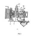
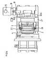
- the device according to the inventionconventionally has a boiler 9 capable of supplying the infusion chamber 1 with hot water for the extraction of the material contained in the pod and especially ground coffee.
- a water circuit 10is present through the device with a portion 11 for admission of hot water into the infusion chamber 1 and an outlet portion 12 opening on a chute 13 spilling the beverage in a funnel 14 to the container of the user.
- the end portion of this circuitmay be formed in the external form of a traditional filter holder comprising a handle here represented by the lever 15 and a funnel portion 14.
- the pods used for the operation of the present inventionmay be of type known on the market today.
- the pods 2comprising a substantially flat and rigid periphery ensuring a maintenance in the form of the pod.
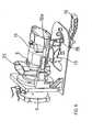
- the brewing chamber 1consists of two parts 3, 4 able to be brought together to close the chamber 1 as shown in FIG. 2 or to be moved away to open it as is apparent from FIG.
- the part 3which moves in translation to move closer to or away from the other part 4.
- part 3is animated with a limited stroke rotation movement to pass between various positions during operation.
- the same drive meansis used to ensure the translation and rotation of the mobile part 3.
- the single drive meansmay be constituted by a cam 16 rotated and having an outer surface having two parts.
- a first part of the outer surface 17 of the cam 16ensures the support of the cam on a translational member adapted to transmit the translational movement to the movable part 3.
- the second outer surface of the cam 16, marked surface 18, in Figure 1provides support for an end of a pivoting arm 19 whose pivoting movement is reflected in the movable portion 3 to achieve its rotation.
- the coupling between the pivoting arm 19 and the mobile part 3may be effected by means of a finger 22 inserted into a fork 23 of the movable part as shown in FIG.
- the pivot axis of the pivoting arm 19is carried by a coupling part 21 also visible in FIG. 1 and marked in FIG.
- the pivoting arm 19comprises a limit-limiting extension 20 and able to abut with an abutment surface when a predetermined angular position of the movable part 3 is reached.
- the cam 16is rotated by a motor.
- the rotational drive of the cam 16is effected by means of a lever 15 which can be actuated by the user.
- FIGS 6 and 7illustrate two positions of the lever 15.
- the lever position 15is such that it implies a position of the cam 16 substantially corresponding to the operating phase of FIG. 1.
- the movable portion 3is inclined downwards to make a stop surface 6 at its upper portion to cooperate with the lower outer surface of the pod 2.
- the surface 6thus constitutes a stop in the feeding phase of the pod 2.
- the stroke of the lever 15may be limited in rotation by means of a stop 28 of current design for example in the form of a finger adapted to move in an oblong hole secured to the frame of the device.
- an additional clamping means closing the two parts 3, 4 of the infusion chamber 1is formed in addition, as described more precisely later.
- the devicealso comprises means for guiding the pod 2 during its displacement during the operating phases.
- guiding meansin the form of a slide 25 constituted by two grooves 26 able to frame the periphery of the pod 2.
- the periphery of said pod 2can be inserted into each of the grooves 26 thus formed.
- Guide meansare advantageously mounted translative to follow the movement of approximation or removal of the two parts.
- the pusher 31comprises a crenel portion 32 adapted to form two bearing portions of the pusher 31 on a corresponding surface of the guide means.
- the vacuum formed between the two bearing surfaces formed by the crenel 32provides a delay in the displacement of the guide means capable of first ensuring an advance of the movable portion 3 only and a coupled advance of the guide means and from the movable part 3 to the fixed part 4.
- the pusher system thus constitutedcan be made guided around two lateral guides 30a, 30b providing guidance in translation of the movable elements and the cohesion of the component parts of the device.
- FIGS. 8 to 14The operating phases of the present device are more particularly illustrated in FIGS. 8 to 14.
- FIG. 8schematizes the different mobilities of the part 3 of the infusion chamber 1.
- the arrowsschematize the translation adapted to be operated by the mobile part 3 by means of the cam 16.
- the sections A-A and B-B of FIG. 8also illustrate schematically the production of the cam 16 and particularly the formation of two external bearing surfaces 17 and 18.
- the surface 18is able to receive the end of the pivoting arm 19.
- the movable portion 3also continues to rotate so as to achieve a situation substantially parallel to that of the fixed portion 4 before the translational movement puts them in contact. This is visible in Figures 9bis and 10bis. In this way, the docking of the movable part 3 operates optimally over the entire contact surface of the two parts 3, 4 in the closed position.
- the drinkis recovered in the chute then in the funnel.
- the mobile part slipping, the pod 2can be released and fall by gravity to a recovery zone.
- Figures 13 and 14illustrate in side view the realization of the translational movement of the guide means when they are present.
- the pusher 31is shown capable of causing the advancement of the guiding means 25 as the moving part 3 advances.
- the crenel 32 present on the pusher 31however provides a delay in the translation of the guide means 25.
- Figure 14illustrates the end of the evacuation of the pod 2 which occurs as soon as the movable portion 3 is retracted and while the guide means 25 are still in position.
- the guide means 25are in turn translated in the direction of the indicated hollow arrow.
- the delay in the translation of the guide means 25ensures the good detachment of the pod 2 before returning to the full initial position of the device.
- the single drive meansis constituted by a drive shaft 33 of horizontal axis of rotation and capable of generating the movements of the movable part 3.
- the shaft 33cooperates with at least one rod 34a, 34b but preferably two rods.
- the rod 34a, 34bis pivotably mounted 35, 36 on the one hand on the shaft 33 and on the other hand, on the rear end of the movable part 3.
- a translational member 21is also provided to integrally follow the translational movement of the movable part 3 and to ensure pivot articulation along the axis 8 of said movable part 3.
- the translation of the member 21is further guided by guide means which may be constituted by two lateral guides 30a, 30b as is apparent from Figure 16.
- the shaft 33is rotated by a motor.
- the rotational driveis effected by means of a lever 15 which can be actuated by the user.
- the movable portion 3is inclined downwards to make a stop surface 6 at its upper portion to cooperate with the lower outer surface of the pod 2.
- the surface 6thus constitutes a stop in the feeding phase of the pod 2.
- an additional clamping means closing the two parts 3, 4 of the infusion chamber 1is formed in addition, as described below.
- the devicealso comprises means for guiding the pod 2 during its displacement during the operating phases.
- guiding meansin the form of a slide 25 constituted by two grooves 26 able to frame the periphery of the pod 2.
- the periphery of said pod 2can be inserted into each of the grooves 26 thus formed.
- Guide meansare advantageously mounted translative to follow the movement of approximation or removal of the two parts.
- these meanshave a displacement coupled to that of the translational member 21 by means of pushers 31 shown in particular in FIG. 17.
- the pusher 31comprises a crenel portion 32 adapted to form two bearing portions of the pusher 31 on a corresponding surface of the guide means.
- the vacuum formed between the two bearing surfaces formed by the crenel 32provides a delay in the displacement of the guide means capable of first ensuring an advance of the movable portion 3 only and a coupled advance of the guide means and from the movable part 3 to the fixed part 4.
- the pusher system thus constitutedcan be made guided around two lateral guides 30a, 30b providing guidance in translation of the movable elements and the cohesion of the component parts of the device.
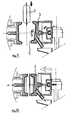
- FIGS. 17 and 18show a first operating position of the device in which the pod 2 is in an abutment position on the upper wall of the movable part 3.
- the lever 15is it in a predetermined angular position here vertical.
- Actuation of the lever 15 in the trigonometric directionmakes it possible to reach the position illustrated in FIGS. 19 and 20 in which the pod 2 is received in the mobile part 3.
- the drive shaft 33has caused a support of the link 34a on the rear portion of the movable portion 3 and has particularly caused a rotation of the movable portion in the clockwise direction.
- the shaft 33By continuing the rotation of the lever 15, the shaft 33 generates an additional thrust on the movable portion 3 by means of the rods 34a, 34b, this additional thrust tending to the translation of the movable part 3 and its closure to constitute the extraction chamber 1.
- the mobile part 3closes the extraction chamber 1.
- the drinkis recovered in the chute 13.
- the mobile part slipping, the pod 2can be released and fall by gravity to a recovery zone.
- FIGS 17, 19 and 21illustrate in side view the realization of the translational movement of the guide means when they are present.
- the pusher 31is shown capable of causing the advancement of the guiding means 25 as the moving part 3 advances.
- the crenel 32 present on the pusher 31however provides a delay in the translation of the guide means 25.
- the end of the evacuation of the pod 2takes place as soon as the movable part 3 is moved backwards and while the guide means 25 are still in position.
- the actuationcan be carried out manually by means of a handle or a lever. Sealing is ensured or perfect through additional clamping means. This provides a lightweight design machine while maintaining its effectiveness and in particular a good seal.
- the additional clamping meansensure a small displacement displacement in translation of the fixed part in rotation 4.
- this displacement of short translational strokemakes it possible to ensure or reinforce the relative support of the two parts 3, 4 at the peripheral zone of the pod 2. A sealing zone is thus created. device 49 particularly visible in Figure 24.
- the translational displacement meansare formed by a jack 38 here implanted typically in the device.
- the cylinder 38is hydraulic and powered by the same source as the brewing chamber 1, namely the boiler 9. In this way, the additional clamping means do not require the formation of another hydraulic circuit.
- the piston element of the jack 38is formed by a movable member 41 secured to the fixed part in rotation 4 so as to allow its advance or recoil following the activation position of the jack 38.
- pressurized fluidin particular the hot water coming from the boiler 9) is adapted to be received in a chamber 39 to effect the thrust of the movable member 41.
- the chamber 39is formed between the movable member 41 and a face 40 of the boiler 9, the face 40 advantageously comprising a slight recess allowing the formation of a sufficient volume for the chamber 39.
- the boiler 9has an outlet 42 allowing hot water to enter the chamber 39.
- sealing meansare present. They may be constituted by joints but, preferably, by means of an elastic sealing membrane 43 still visible in FIGS. 23 and 24.
- the elastic sealing membraneis formed of a substantially annular element integrally connected and sealed by its outer periphery at the face 40 of the boiler and, by its inner periphery at the mobile member 41.
- the elastic sealing membrane 43is deformed according to the activation state of the cylinder 38.
- the hot watercan be injected at the part 4 so as to produce the forced leaching in the brewing chamber 1.
- This injectionoccurs at a spray head 45 of current design constituting a liner of part 4.
- the injection of hot water into the infusion chamber 1is carried out via a feed passage 44 connecting the chamber 39 of the cylinder 38 and the hand shower 45.
- a feed passage 44connecting the chamber 39 of the cylinder 38 and the hand shower 45.
- the feed passage 44comprises a valve 46 configured to open the feed passage 44 only beyond a pressure threshold of a value greater than the working pressure of the cylinder 38.
- the triggering pressure threshold of the valve 46it is possible to set the triggering pressure threshold of the valve 46 to a level of the order of 2 bars. This adjustment can be made by the choice of the spring 48 ensuring the return to the rest position (shutter) of the valve 46.
- the additional clamping meansensure perfect sealing of the infusion chamber 1 at the peripheral sealing zone. The leaching can then occur, and with pressures that can perfectly match the pressures of espresso type machines and in particular of the order of 15 bars.
Landscapes
- Engineering & Computer Science (AREA)
- Mechanical Engineering (AREA)
- Food Science & Technology (AREA)
- Apparatus For Making Beverages (AREA)
- Tea And Coffee (AREA)
- Non-Alcoholic Beverages (AREA)
- Devices For Dispensing Beverages (AREA)
- Control Of Driving Devices And Active Controlling Of Vehicle (AREA)
- Reverberation, Karaoke And Other Acoustics (AREA)
Abstract
Description
Translated fromFrenchLa présente invention concerne un dispositif de production de boisson par infusion d'un produit contenu dans une dosette.The present invention relates to a beverage production device by infusion of a product contained in a pod.
Elle trouvera particulièrement son application dans le domaine de la production de café à partir de mouture de café préemballée dans des dosettes.It will particularly find application in the field of coffee production from prepackaged coffee grounds in pods.
De telles dosettes existent par ailleurs déjà et sont généralement constituées sous forme d'un assemblage de deux feuilles de papier filtre réalisant un espace intermédiaire d'emballage de mouture de café.Such pods already exist and are generally constituted in the form of an assembly of two sheets of filter paper providing an intermediate space for packing coffee grounds.
Diverses machines d'extraction de boissons chaudes à partir de mouture sont connues.Various machines for extracting hot drinks from milling are known.
Particulièrement, le document WO-A-00/38558 divulgue une chambre d'extraction pour machine automatique pour la préparation de boissons chaudes dans laquelle la chambre d'extraction est prévue pour recevoir des dosettes ou pastilles prédosées en café moulu.In particular, the document WO-A-00 /38558 discloses an extraction chamber for an automatic machine for the preparation of hot drinks in which the extraction chamber is designed to receive pods or pellets pre-dosed in ground coffee.
La chambre est constituée de deux parties, chacune mobile dans un plan horizontale manière à pouvoir s'écarter ou se rapprocher l'une de l'autre.The chamber is made up of two parts, each movable in a horizontal plane so as to be able to move away from or close to each other.
Par ailleurs, selon ce document, les deux parties sont également mobiles de façon oscillante.Moreover, according to this document, the two parts are also oscillatingly mobile.
Une machine ainsi équipée donne globalement satisfaction mais nécessite l'entraînement des deux parties constitutives de la chambre.A machine thus equipped gives overall satisfaction but requires the training of the two constituent parts of the room.
Il faut donc prévoir une motorisation suffisamment puissante et un système de transmission de puissance relativement complexe nécessitant la synchronisation des mouvements.It is therefore necessary to provide a sufficiently powerful motor and a relatively complex power transmission system requiring the synchronization of the movements.
On connaît par ailleurs, du document FR-A-2.745.995 un appareil pour la fabrication de boissons dans lequel la chambre d'infusion est constituée par deux demi logements, l'un porté par une face du corps de l'appareil, l'autre fixé sur une face de la chaudière, ces deux faces étant en regard l'une de l'autre.Document FR-A-2,745,995 discloses an apparatus for the manufacture of beverages in which the infusion chamber is constituted by two half-housings, one carried by oneof the body of the apparatus the other fixed on one face of the boiler, these two faces facing each other.
La chambre d'infusion est formée lorsque les deux demi logements se jouxtent.The infusion chamber is formed when the two half-houses are adjacent.
Cet assemblage de la chambre s'effectue par un mouvement de translation de l'un des logements.This assembly of the chamber is effected by a translational movement of one of the housing.
L'appareil ainsi présenté nécessite l'association de différents moyens de butée assurant la rétention de la dosette au moment de l'alimentation puis lors de son entrée dans la chambre d'infusion.The apparatus thus presented requires the combination of different stop means ensuring the retention of the pod at the time of feeding and then when entering the brewing chamber.
Une mobilité des moyens de butées est également nécessaire pour assurer l'éjection des doses usagées.Mobility of the stop means is also necessary to ensure the ejection of used doses.
L'art antérieur divulgué par cette antériorité impose la réalisation distincte de moyens de butée et d'éjection des dosettes.The prior art disclosed by this prior art requires the separate realization of stop means and ejection pods.
On connaît du document US 5 520 093 une machine à café pour dosettes en bande dans laquelle la chambre d'infusion comporte une partie mobile en rotation et en translation au moyen d'un organe formant came. Outre le caractère fort complexe de la mise en place et d'éjection des dosettes, ce document présente un actionnement complexe et fort lourd impliquant obligatoirement de réaliser l'étanchéité de la chambre par l'intermédiaire du système à came.No. 5,520,093 discloses a coffee machine for strip pods in which the brewing chamber comprises a part movable in rotation and in translation by means of a cam member. In addition to the very complex nature of the introduction and ejection pods, this document has a complex actuation and very heavy involving mandatory sealing of the chamber through the cam system.
Le document EP 1 153 561 présente quant à lui une machine à café pour capsule avec un capot mobile pour ouvrir ou fermer la chambre d'infusion. Un système complexe est également prévu pour appliquer la capsule de façon serrée.
Compte tenu de l'actionnement actuel des chambres d'infusion, les moyens de mise en mouvement des parties de la chambre doivent être conçus de façon lourde et complexe, en particulier pour assurer l'étanchéité en position fermée. Il faut en effet tenir compte du fait qu'une machine de type espresso produit une eau chaude à une pression souvent de l'ordre de 15 bars.Given the current actuation of the brewing chambers, the means for moving parts of the chamber must be designed in a heavy and complex manner, in particular to ensure sealing in position closed. It must be taken into account that an espresso-type machine produces hot water at a pressure often of the order of 15 bars.
La présente invention permet de remédier à ces inconvénients.The present invention overcomes these disadvantages.
Elle présente pour ce faire un dispositif de production de boisson amélioré.To this end, it has an improved beverage production device.
Un premier avantage de l'invention est de permettre la réalisation des phases d'ouverture et de fermeture de la chambre d'infusion ainsi que la réalisation des phases d'introduction et d'éjection de dosettes par l'intermédiaire d'un moins grand nombre de mouvements et, particulièrement, par le mouvement de rotation de translation combinée d'une seule des parties constitutives de la chambre.A first advantage of the invention is to allow the realization of the opening and closing phases of the brewing chamber and the realization of the introduction and ejection phases pods via a smaller number of movements and, particularly, by the combined translational rotation movement of only one of the constituent parts of the chamber.
Un autre avantage de l'invention est de ne nécessiter, dans un mode préféré de réalisation, qu'un seul moyen d'entraînement pour un mouvement de rotation et un mouvement de translation assurant ainsi à coup sûr et à moindre frais la synchronisation.Another advantage of the invention is to require, in a preferred embodiment, only one drive means for a rotational movement and a translational movement thus ensuring for sure and inexpensively synchronization.
Suivant une variante préférée, l'invention est telle qu'elle peut être utilisée et actionnée par un utilisateur par le biais d'un levier.According to a preferred variant, the invention is such that it can be used and actuated by a user by means of a lever.
L'usage du dispositif ici proposé peut donc s'apparenter à celui d'une machine conventionnelle présentant un porte filtre à poignée, tout en réalisant les phases d'extraction de la boisson de façon automatique.The use of the device proposed here may be similar to that of a conventional machine having a filter holder handle, while performing the extraction phases of the beverage automatically.
Un moyen de serrage additionnel fonctionne en complément pour assurer ou parfaire l'étanchéité de la chambre en position de lixiviation.An additional clamping means operates in addition to ensure or complete the sealing of the chamber in the leaching position.
D'autres buts et avantages apparaîtront au cours de la description qui suit d'un mode de réalisation préféré de l'invention qui n'est cependant pas limitatif.Other objects and advantages will become apparent from the following description of a preferred embodiment of the invention which is however not limiting.
La présente invention concerne un dispositif de production de boisson par infusion d'un produit contenu dans une dosette, comportant une chambre d'infusion apte à recevoir une dosette et comprenant deux parties configurées pour être rapprochées ou éloignées pour fermer ou ouvrir la chambre d'infusion, dispositif tel que l'une seulement des parties a une mobilité en rotation apte à mettre en butée la dosette dans ladite partie et que la partie mobile en rotation a une mobilité en translation pour ouvrir ou fermer la chambre d'infusion, caractérisé par le fait qu'il comporte des moyens additionnels de serrage en fermeture des deux parties de la chambre d'infusion qui sont des moyens de déplacement en translation de la partie fixe en rotation.The present invention relates to a beverage production device by infusion of a product contained in a pod, comprising a brewing chamber capable of receiving a pod and comprising two parts configured to be moved closer or further apart to close or open the chamber. infusion, device such that only one of the parts has a rotational mobility able to abut the pod in said portion and the rotatable portion has a mobility in translation to open or close the brewing chamber, characterized in that it comprises additional clamping means in closing the two parts of the brewing chamber which are means for translational movement of the fixed portion in rotation.
Suivant des variantes préférées, le dispositif est tel que :
- les moyens de déplacement sont constitués par un vérin,
- le vérin est hydraulique et alimenté par la chaudière alimentant la chambre d'infusion,
- la chambre du vérin est formée entre une face de la chaudière et un organe mobile solidaire de la partie fixe en rotation de la chambre d'infusion, la face comportant une sortie d'alimentation en eau chaude,
- il comporte une membrane élastique d'étanchéité entre ladite face et ledit organe mobile pour fermer de façon étanche la chambre du vérin,
- l'organe mobile comporte un passage d'alimentation de la chambre d'infusion formé entre la chambre du vérin et une douchette présente sur la partie fixe en rotation,
- le passage d'alimentation présente une soupape configurée pour ouvrir le passage d'alimentation à partir d'une pression supérieure à la pression de travail du vérin,
- il comporte un ressort de rappel de l'organe mobile du vérin,
- il comporte un moyen d'entraînement commun pour la mobilité en rotation et la mobilité en translation de la partie mobile,
- le moyen d'entraînement est une came présentant :
- une première surface extérieure d'appui d'un organe translatif couplé à la partie mobile ;
- une deuxième surface extérieure d'appui d'une extrémité d'un bras pivotant couplé à la partie mobile ;
- la came est actionnée en rotation par un levier,
- le moyen d'entraînement commun comporte un arbre d'entraînement rotatif couplé à la partie mobile par au moins une biellette montée pivotante entre ledit arbre d'entraînement et ladite partie mobile,
- il comporte un organe translatif solidaire de la partie mobile dans son mouvement de translation et par rapport auquel elle est mobile en rotation,
- il présente des moyens de guidage en translation de l'organe translatif,
- l'arbre est actionné en rotation par un levier,
- il comporte des moyens de guidage de la dosette,
- les moyens de guidage comprennent une glissière avec au moins une rainure apte à recevoir la périphérie d'une dosette,
- les moyens de guidage sont montés translatifs pour suivre le mouvement de rapprochement ou d'éloignement des parties,
- la mobilité de la partie mobile est configurée pour faire face à la partie fixe de façon parallèle avant leur mise en contact, durant la phase de fermeture de la chambre d'infusion.
- the displacement means are constituted by a jack,
- the cylinder is hydraulic and fed by the boiler feeding the infusion chamber,
- the cylinder chamber is formed between a face of the boiler and a movable member secured to the fixed portion in rotation of the infusion chamber, the face having a hot water supply outlet,
- it comprises a resilient sealing membrane between said face and said movable member for sealing the chamber of the jack,
- the movable member comprises a supply passage of the infusion chamber formed between the cylinder chamber and a handshower present on the fixed portion in rotation,
- the feed passage has a valve configured to open the feed passage from a pressure greater than the operating pressure of the ram,
- it comprises a return spring of the movable member of the jack,
- it comprises a common drive means for the mobility in rotation and the mobility in translation of the moving part,
- the drive means is a cam having:
- a first outer bearing surface of a translational member coupled to the movable portion;
- a second outer bearing surface of one end of a pivoting arm coupled to the movable portion;
- the cam is rotated by a lever,
- the common drive means comprises a rotary drive shaft coupled to the movable part by at least one rod pivotally mounted between said drive shaft and said movable part,
- it comprises a translational member integral with the mobile part in its translational movement and with respect to which it is rotatable,
- it has guide means in translation of the translational member,
- the shaft is rotated by a lever,
- it comprises means for guiding the pod,
- the guide means comprise a slide with at least one groove adapted to receive the periphery of a pod,
- the guide means are mounted translectively to follow the movement of approximation or removal of the parts,
- the mobility of the moving part is configured to face the fixed part in parallel manner before they come into contact during the closing phase of the brewing chamber.
Les dessins ci-joints sont donnés à titre d'exemples et ne sont pas limitatifs de l'invention. Ils représentent seulement un mode de réalisation de l'invention et permettront de la comprendre aisément.
- La figure 1 est une vue en coupe du dispositif selon un premier mode de réalisation de l'invention.
- La figure 2 est une autre vue en coupe dans une configuration différente de la chambre d'infusion.
- La figure 3 est une vue de côté du dispositif selon l'invention.
- Les figures 4
et 5 en sont respectivement des vues de dessus et une vue de face. - La figure 6 est une vue en perspective du dispositif lors d'une phase d'extraction du café.
- La figure 7 est une vue en perspective du dispositif en position de chargement d'une dosette.
- La figure 8 illustre schématiquement les phases de mouvement du dispositif selon l'invention.
- Les figures 9 à 12
et 9 bis, 10bis illustrent quatre étapes successives de fonctionnement du dispositif. - Les figures 13 et 14 présentent en vue de côté, le mouvement de translation des moyens de guidage.
- La figure 15 est une vue générale en perspective du dispositif de l'invention.
- La figure 16 en est une vue de dessus.
- Les figures 17 et 18 sont respectivement des vues de côté et en coupe longitudinale du dispositif de l'invention en position d'alimentation en dosettes.
- Les figures 19 et 20 sont respectivement des vues de côté et en coupe du dispositif de l'invention dans une position de réception de dosettes dans la chambre d'infusion.
- Les figures 21 et 22 sont respectivement des vues de côté et en coupe longitudinale du dispositif de l'invention en position d'extraction.
- La figure 23 montre partiellement en coupe le dispositif avec un mode préféré de réalisation des moyens additionnels de serrage en position de repos.
- La figure 24 en montre une position active de serrage.
- Figure 1 is a sectional view of the device according to a first embodiment of the invention.
- Figure 2 is another sectional view in a different configuration of the infusion chamber.
- Figure 3 is a side view of the device according to the invention.
- Figures 4 and 5 are respectively top views and a front view.
- Figure 6 is a perspective view of the device during a coffee extraction phase.
- Figure 7 is a perspective view of the device in the loading position of a pod.
- Figure 8 schematically illustrates the movement phases of the device according to the invention.
- Figures 9 to 12 and 9a, 10a illustrate four successive steps of operation of the device.
- Figures 13 and 14 show in side view, the translational movement of the guide means.
- Figure 15 is a general perspective view of the device of the invention.
- Figure 16 is a view from above.
- Figures 17 and 18 are respectively side views and longitudinal section of the device of the invention in dosing position.
- Figures 19 and 20 are respectively side views and in section of the device of the invention in a pod receiving position in the brewing chamber.
- Figures 21 and 22 are respectively side views and longitudinal section of the device of the invention in the extraction position.
- FIG. 23 partially shows in section the device with a preferred embodiment of the additional clamping means in the rest position.
- Figure 24 shows an active clamping position.
En se référant aux figures et particulièrement aux figures 6 et 7, le dispositif selon l'invention présente de façon conventionnelle une chaudière 9 apte à alimenter la chambre d'infusion 1 en eau chaude pour l'extraction de la matière contenue dans la dosette et particulièrement du café moulu.Referring to the figures and particularly to FIGS. 6 and 7, the device according to the invention conventionally has a
Tel que présenté en figure 2, un circuit d'eau 10 est présent au travers du dispositif avec une partie 11 d'admission de l'eau chaude dans la chambre d'infusion 1 et une partie de sortie 12 débouchant sur une goulotte 13 déversant la boisson dans un entonnoir 14 jusqu'au récipient de l'utilisateur.As shown in Figure 2, a
Tel que représenté sur les figures 1 à 14, la partie terminale de ce circuit peut être constituée sous la forme extérieure d'un porte filtre traditionnel comportant une poignée ici représentée par le levier 15 et une partie formant entonnoir 14.As shown in FIGS. 1 to 14, the end portion of this circuit may be formed in the external form of a traditional filter holder comprising a handle here represented by the
Les dosettes utilisées pour le fonctionnement de la présente invention pourront être de type connues sur le marché actuellement.The pods used for the operation of the present invention may be of type known on the market today.
De préférence mais de façon non limitative, on pourra utiliser les dosettes 2 comprenant une périphérie sensiblement plate et rigide assurant un maintien en forme de la dosette.Preferably, but in a nonlimiting manner, it is possible to use the
La chambre d'infusion 1 est constituée de deux parties 3, 4 aptes à être rapprochées pour fermer la chambre 1 tel que cela apparaît en figure 2 ou à être éloignées pour l'ouvrir comme cela ressort de la figure 1.The
De façon préférentielle, et pour la suite de la description, c'est la partie 3 qui se déplace en translation pour se rapprocher ou s'éloigner de l'autre partie 4.Preferably, and for the rest of the description, it is the
Par ailleurs, la partie 3 est animée d'un mouvement de rotation de course limitée pour passer entre divers positions lors du fonctionnement.In addition, the
A titre préféré, on utilise un même moyen d'entraînement pour assurer la translation et la rotation de la partie mobile 3.As a preference, the same drive means is used to ensure the translation and rotation of the
On décrit ci-après successivement deux variantes de réalisation de ce moyen d'entraînement.Two embodiments of this drive means are successively described below.
On se réfère ici aux figures 1 à 14Reference is made here to FIGS. 1 to 14
On a repéré à titre d'exemple, en figure 2, la position de l'axe 8 de rotation de la partie mobile 3 et l'axe 7 de sa translation.The position of the
Pour la suite de la description et en référence aux dessins, on se place dans un exemple de machine à extraction horizontale (dans laquelle la dosette est positionnée sensiblement verticalement et reçoit l'eau chaude suivant un circuit sensiblement horizontal).For the following description and reference to the drawings, we place in an example of horizontal extraction machine (in which the pod is positioned substantially vertically and receives the hot water in a substantially horizontal circuit).
Cependant, d'autres orientations sont possibles sans sortir du cadre de l'invention.However, other orientations are possible without departing from the scope of the invention.
Le moyen unique d'entraînement pourra être constitué par une came 16 actionnée en rotation et présentant une surface extérieure comportant deux parties.The single drive means may be constituted by a
Une première partie de la surface extérieure 17 de la came 16 assure l'appui de la came sur un organe translatif apte à transmettre le mouvement de translation à la partie mobile 3.A first part of the
La deuxième surface extérieure de la came 16, repérée surface 18, en figure 1, assure l'appui d'une extrémité d'un bras pivotant 19 dont le mouvement de pivot est répercuté à la partie mobile 3 pour réaliser sa rotation.The second outer surface of the
Le couplage entre le bras pivotant 19 et la partie mobile 3 pourra être effectué au moyen d'un doigt 22 s'insérant dans une fourchette 23 de la partie mobile tel que représenté en figure 1.The coupling between the pivoting
L'axe du pivot du bras pivotant 19 est porté par une pièce de couplage 21 également visible en figure 1 et repérée en figure 2.The pivot axis of the pivoting
C'est cette pièce de couplage qui entraîne en translation la partie mobile 3 par appui sur la came 16.It is this coupling piece which drives in translation the
D'autres moyens de transmission des mouvements de rotation et de translation à la partie mobile 3 sont également envisageables.Other means of transmitting rotational and translational movements to the
A titre préféré, le bras pivotant 19 comporte une extension formant limiteur de course 20 et apte à venir en butée avec une surface de butée lorsqu'une position angulaire prédéterminée de la partie mobile 3 est atteinte.As a preference, the pivoting
Tel est le cas en position d'ouverture vers le haut de la chambre d'infusion 1.This is the case in the upward opening position of the
Suivant une première possibilité, la came 16 est entraînée en rotation par une motorisation.According to a first possibility, the
Suivant une seconde possibilité, envisagée dans les figures, l'entraînement en rotation de la came 16 s'effectue par le biais d'un levier 15 pouvant être actionné par l'utilisateur.According to a second possibility, envisaged in the figures, the rotational drive of the
Les figures 6 et 7 illustrent deux positions du levier 15.Figures 6 and 7 illustrate two positions of the
Dans le cas de la figure 7, la position de levier 15 est telle qu'elle implique une position de la came 16 sensiblement correspondante à la phase de fonctionnement de la figure 1.In the case of FIG. 7, the
Dans ce cadre, la partie mobile 3 est inclinée vers le bas pour réaliser une surface de butée 6 en sa portion supérieure pour coopérer avec la surface extérieure inférieure de la dosette 2.In this context, the
La surface 6 constitue ainsi une butée en phase d'alimentation de la dosette 2.The
Suivant la position du levier 15 illustré à la figure 6, la came 16 a opéré une rotation pour parvenir à la position de fonctionnement illustrée à la figure 2, et dans laquelle la chambre d'infusion 1 est fermée en position d'extraction.Depending on the position of the
La course du levier 15 peut être limitée en rotation par l'intermédiaire d'une butée 28 de conception courante par exemple sous forme d'un doigt apte à se déplacer dans un trou oblong solidaire du châssis du dispositif.The stroke of the
Pour assurer ou optimiser l'étanchéisation de la chambre d'infusion 1 en position fermée, il est avantageux d'ajouter à la pression de fermeture opérée par l'utilisateur au moyen du levier 15, une pression additionnelle.To ensure or optimize the sealing of the
Dans ce cadre, un moyen additionnel de serrage en fermeture des deux parties 3, 4 de la chambre d'infusion 1 est constitué en complément, comme décrit plus précisément par la suite.In this context, an additional clamping means closing the two
De façon avantageuse, le dispositif comprend également des moyens de guidage de la dosette 2 lors de son déplacement durant les phases de fonctionnement.Advantageously, the device also comprises means for guiding the
Dans ce cadre, on pourra constituer des moyens de guidage sous forme d'une glissière 25 constituée par deux rainures 26 aptes à encadrer la périphérie de la dosette 2.In this context, it will be possible to constitute guiding means in the form of a
La périphérie de ladite dosette 2 peut s'insérer dans chacune des rainures 26 ainsi constituées.The periphery of said
Des moyens de guidage sont avantageusement montés translatifs pour suivre le mouvement de rapprochement ou d'éloignement des deux parties.Guide means are advantageously mounted translative to follow the movement of approximation or removal of the two parts.
En ce sens, ces moyens ont un déplacement couplé à celui de l'organe translatif 21 par l'intermédiaire de poussoir 31 représenté notamment en figure 7.In this sense, these means have a displacement coupled to that of the
Le poussoir 31 comprend une partie en créneau 32 apte à constituer deux portions d'appui du poussoir 31 sur une surface correspondante des moyens de guidage.The
De cette façon, le mouvement des moyens de guidage suit celui de l'organe translatif 21 au cours des phases de fonctionnement.In this way, the movement of the guide means follows that of the
Par ailleurs, le vide constitué entre les deux surfaces d'appui formées par le créneau 32 assure un retard dans le déplacement des moyens de guidage apte à assurer d'abord une avance de la partie mobile 3 seule puis une avance couplée du moyen de guidage et de la partie mobile 3 vers la partie fixe 4.Furthermore, the vacuum formed between the two bearing surfaces formed by the
Le système à poussoir ainsi constitué peut être réalisé de façon guidée autour de deux guides latéraux 30a, 30b assurant le guidage en translation des éléments mobiles et la cohésion des pièces constitutives du dispositif.The pusher system thus constituted can be made guided around two
Les phases de fonctionnement du présent dispositif sont plus particulièrement illustrées aux figures 8 à 14.The operating phases of the present device are more particularly illustrated in FIGS. 8 to 14.
La figure 8 schématise les différentes mobilités de la partie 3 de la chambre d'infusion 1.FIG. 8 schematizes the different mobilities of the
Dans ce cadre, les flèches schématisent la translation apte à être opérée par la partie mobile 3 par le biais de la came 16.In this context, the arrows schematize the translation adapted to be operated by the
Les coupes A-A et B-B de la figure 8 illustrent par ailleurs de façon schématique la réalisation de la came 16 et particulièrement la formation de deux surfaces extérieures d'appui 17 et 18.The sections A-A and B-B of FIG. 8 also illustrate schematically the production of the
La surface 18 est apte à recevoir l'extrémité du bras pivotant 19.The
En référence aux figures 9 à 12 et 9bis, 10bis, quatre étapes successives de fonctionnement de l'invention sont illustrées.With reference to FIGS. 9 to 12 and 9bis, 10bis, four successive operating steps of the invention are illustrated.
En figure 9, la came 16 a été actionnée pour provoquer une rotation de la partie mobile 3 tendant à l'ouvrir pour accueillir une dosette 2.In FIG. 9, the
La partie supérieure de la partie mobile 3 s'esquivant, la surface de butée d'alimentation 6 formée jusqu'alors à ce niveau, est escamotée et provoque la chute par gravité de la dosette 2.The upper part of the moving
Celle-ci est alors reçue par la partie mobile 3 dans son volume intérieur et elle s'applique sur la surface 5 constitutive d'une butée de réception.This is then received by the
La poursuite de la rotation de la came 16 induit une translation de la partie mobile 3 qui est figurée à la figure 10.The continued rotation of the
Cependant, la partie mobile 3 poursuit également sa rotation de façon à parvenir à une situation sensiblement parallèle à celle de la partie fixe 4 avant que le mouvement de translation les mette en contact. Cela est visible en figures 9bis et 10bis. De cette façon, l'accostage de la partie mobile 3 s'opère de façon optimale, sur toute la surface de contact des deux parties 3, 4 en position fermée.However, the
Dès que la chambre d'infusion est fermée, l'eau chaude est injectée dans la chambre d'infusion suivant le parcours des flèches creuses illustrées en figure 10.As soon as the brewing chamber is closed, the hot water is injected into the brewing chamber along the path of the hollow arrows illustrated in FIG.
La boisson est récupérée dans la goulotte puis dans l'entonnoir.The drink is recovered in the chute then in the funnel.
Dès que la lixiviation est opérée, un mouvement inverse de la came 16 induit un recul de la partie mobile 3 et son pivot dans le sens trigonométrique.As soon as the lixiviation is operated, a reverse movement of the
La partie mobile s'esquivant, la dosette 2 peut être libérée et chuter par gravité vers une zone de récupération.The mobile part slipping, the
La position ainsi pivotée de la partie mobile 3 vers le bas assure la formation à nouveau de la surface 6 de butée d'alimentation en partie supérieure de la partie mobile 3.The pivoted position of the
Les figures 13 et 14 illustrent en vue de côté la réalisation du mouvement de translation des moyens de guidage lorsque ceux-ci sont présents.Figures 13 and 14 illustrate in side view the realization of the translational movement of the guide means when they are present.
A ce sujet, on visualise le poussoir 31 apte à provoquer l'avancées des moyens de guidage 25 au fur et à mesure de l'avancée de la partie mobile 3.In this regard, the
Le créneau 32 présent sur le poussoir 31 assure cependant un retard dans la translation des moyens de guidage 25.The
La figure 14 illustre la fin de l'évacuation de la dosette 2 qui s'opère dès que la partie mobile 3 est reculée et alors que les moyens de guidage 25 sont encore en position.Figure 14 illustrates the end of the evacuation of the
Une fois que la dosette est évacuée, les moyens de guidage 25 subissent à leur tour une translation dans le sens de la flèche creuse indiquée.Once the pod is evacuated, the guide means 25 are in turn translated in the direction of the indicated hollow arrow.
Le retard opéré dans la translation des moyens de guidage 25 assure le bon décollement de la dosette 2 avant le retour en position initiale complet du dispositif.The delay in the translation of the guide means 25 ensures the good detachment of the
Un autre mode d'actionnement est ici présenté en référence aux figures 15 à 22.Another mode of operation is here presented with reference to FIGS. 15 to 22.
On a repéré à titre d'exemple, en figure 18, la position de l'axe 8 de rotation de la partie mobile 3 et l'axe 7 de sa translation.18, the position of the
Le moyen unique d'entraînement est constitué par un arbre d'entraînement 33 d'axe de rotation horizontal et apte à engendrer les mouvements de la partie mobile 3.The single drive means is constituted by a
Pour ce faire, l'arbre 33 coopère avec au moins une biellette 34a, 34b mais préférentiellement deux biellettes.To do this, the
Tel que cela est visible par exemple en figure 18, la biellette 34a, 34b est montée en liaison pivot 35, 36 d'une part sur l'arbre 33 et d'autre part, sur l'extrémité arrière de la partie mobile 3.As can be seen for example in FIG. 18, the rod 34a, 34b is pivotably mounted 35, 36 on the one hand on the
Un organe translatif 21 est également prévu pour suivre solidairement le mouvement de translation de la partie mobile 3 et assurer l'articulation en pivot selon l'axe 8 de ladite partie mobile 3.A
La translation de l'organe 21 est en outre guidée par des moyens de guidage qui pourront être constitués par deux guides latéraux 30a, 30b comme cela ressort de la figure 16.The translation of the
Suivant une première possibilité, l'arbre 33 est entraîné en rotation par une motorisation.According to a first possibility, the
Suivant une seconde possibilité, envisagée dans les figures, l'entraînement en rotation s'effectue par le biais d'un levier 15 pouvant être actionné par l'utilisateur.According to a second possibility, envisaged in the figures, the rotational drive is effected by means of a
Dans ce cadre, la partie mobile 3 est inclinée vers le bas pour réaliser une surface de butée 6 en sa portion supérieure pour coopérer avec la surface extérieure inférieure de la dosette 2.In this context, the
La surface 6 constitue ainsi une butée en phase d'alimentation de la dosette 2.The
Pour optimiser l'étanchéisation de la chambre d'infusion 1 en position fermée, il est avantageux d'ajouter à la pression de fermeture opérée par l'utilisateur au moyen du levier 15, une pression additionnelle.To optimize the sealing of the
Dans ce cadre, un moyen additionnel de serrage en fermeture des deux parties 3, 4 de la chambre d'infusion 1 est constitué en complément, comme décrit plus loin.In this context, an additional clamping means closing the two
De façon avantageuse, le dispositif comprend également des moyens de guidage de la dosette 2 lors de son déplacement durant les phases de fonctionnement.Advantageously, the device also comprises means for guiding the
Dans ce cadre, on pourra constituer des moyens de guidage sous forme d'une glissière 25 constituée par deux rainures 26 aptes à encadrer la périphérie de la dosette 2.In this context, it will be possible to constitute guiding means in the form of a
La périphérie de ladite dosette 2 peut s'insérer dans chacune des rainures 26 ainsi constituées.The periphery of said
Des moyens de guidage sont avantageusement montés translatifs pour suivre le mouvement de rapprochement ou d'éloignement des deux parties.Guide means are advantageously mounted translative to follow the movement of approximation or removal of the two parts.
En ce sens, ces moyens ont un déplacement couplé à celui de l'organe translatif 21 par l'intermédiaire de poussoirs 31 représentés notamment en figure 17.In this sense, these means have a displacement coupled to that of the
Le poussoir 31 comprend une partie en créneau 32 apte à constituer deux portions d'appui du poussoir 31 sur une surface correspondante des moyens de guidage.The
De cette façon, le mouvement des moyens de guidage suit celui de l'organe translatif 21 au cours des phases de fonctionnement.In this way, the movement of the guide means follows that of the
Par ailleurs, le vide constitué entre les deux surfaces d'appui formées par le créneau 32 assure un retard dans le déplacement des moyens de guidage apte à assurer d'abord une avance de la partie mobile 3 seule puis une avance couplée du moyen de guidage et de la partie mobile 3 vers la partie fixe 4.Furthermore, the vacuum formed between the two bearing surfaces formed by the
Le système à poussoir ainsi constitué peut être réalisé de façon guidée autour de deux guides latéraux 30a, 30b assurant le guidage en translation des éléments mobiles et la cohésion des pièces constitutives du dispositif.The pusher system thus constituted can be made guided around two
Les phases de fonctionnement du présent dispositif sont plus particulièrement illustrées aux figures 17 à 22 et permettent la réalisation des étapes de fabrication de la boisson avec les mêmes modifications de configuration de la chambre d'infusion 1 que dans le cas du 1er mode de réalisation.The operating phases of the present device are more particularly illustrated in Figures 17 to 22 and allow the realization of the steps of the beverage maker with the
Les figures 17 et 18 montrent une première position de fonctionnement du dispositif dans laquelle la dosette 2 est en position de butée sur la paroi supérieure de la partie mobile 3.FIGS. 17 and 18 show a first operating position of the device in which the
Le levier 15 est lui dans une position angulaire prédéterminée ici verticale.The
Un actionnement du levier 15 dans le sens trigonométrique permet de parvenir à la position illustrée aux figures 19 et 20 dans lesquelles la dosette 2 est reçue dans la partie mobile 3.Actuation of the
Entre ces deux phases de mouvement, l'arbre d'entraînement 33 a provoqué un appui de la biellette 34a sur la partie arrière de la partie mobile 3 et a particulièrement provoqué une rotation de la partie mobile dans le sens horaire.Between these two phases of movement, the
En poursuivant la rotation du levier 15, l'arbre 33 engendre une poussée supplémentaire sur la partie mobile 3 par l'intermédiaire des biellettes 34a, 34b, cette poussée supplémentaire tendant à la translation de la partie mobile 3 et à sa fermeture pour constituer la chambre d'extraction 1.By continuing the rotation of the
On peut prévoir des surfaces de butée notamment sur l'organe translatif 21 pour limiter la mobilité angulaire de la partie mobile 3.It is possible to provide abutment surfaces, in particular on the
Ainsi, dans la position représentée aux figures 21 et 22, la partie mobile 3 clôt la chambre d'extraction 1.Thus, in the position shown in FIGS. 21 and 22, the
Quand la chambre d'infusion est fermée, l'eau chaude est injectée dans la chambre d'infusion.When the brewing chamber is closed, hot water is injected into the brewing chamber.
La boisson est récupérée dans la goulotte 13.The drink is recovered in the
Dès que la lixiviation est opérée, un mouvement inverse de l'arbre 33 induit un recul de la partie mobile 3 et son pivot dans le sens trigonométrique.As soon as the leaching is carried out, an inverse movement of the
La partie mobile s'esquivant, la dosette 2 peut être libérée et chuter par gravité vers une zone de récupération.The mobile part slipping, the
La position ainsi pivotée de la partie mobile 3 vers le bas assure la formation à nouveau de la surface 6 de butée d'alimentation en partie supérieure de la partie mobile 3.The pivoted position of the
Les figures 17, 19 et 21 illustrent en vue de côté la réalisation du mouvement de translation des moyens de guidage lorsque ceux-ci sont présents.Figures 17, 19 and 21 illustrate in side view the realization of the translational movement of the guide means when they are present.
A ce sujet, on visualise le poussoir 31 apte à provoquer l'avancée des moyens de guidage 25 au fur et à mesure de l'avancée de la partie mobile 3.In this regard, the
Le créneau 32 présent sur le poussoir 31 assure cependant un retard dans la translation des moyens de guidage 25.The
La fin de l'évacuation de la dosette 2 s'opère dès que la partie mobile 3 est reculée et alors que les moyens de guidage 25 sont encore en position.The end of the evacuation of the
Dans les deux modes de réalisation ainsi présentés, l'actionnement peut s'effectuer manuellement par le biais d'une poignée ou d'un levier. L'étanchéité est assurée ou parfaite par le biais des moyens additionnels de serrage. On obtient ainsi une machine de conception allégée tout en maintenant son efficacité et en particulier une bonne étanchéité.In the two embodiments thus presented, the actuation can be carried out manually by means of a handle or a lever. Sealing is ensured or perfect through additional clamping means. This provides a lightweight design machine while maintaining its effectiveness and in particular a good seal.
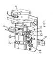
On décrit maintenant un mode de réalisation préféré des moyens additionnels de serrage, plus particulièrement en référence aux figures 23 et 24.A preferred embodiment of the additional clamping means is now described, more particularly with reference to FIGS. 23 and 24.
Dans le cas représenté aux figures 23 et 24, les moyens additionnels de serrage assurent un déplacement d'une faible course en translation de la partie fixe en rotation 4. De cette façon, dès que la partie mobile 3 est parvenue en position de fermeture de la chambre d'infusion 1, ce déplacement de faible course en translation permet d'assurer ou de renforcer l'appui relatif des deux parties 3, 4 au niveau de la zone périphérique de la dosette 2. On crée ainsi une zone d'étanchéité périphérique 49 particulièrement visible en figure 24.In the case shown in FIGS. 23 and 24, the additional clamping means ensure a small displacement displacement in translation of the fixed part in
Suivant le mode de réalisation illustré, les moyens de déplacement en translation sont formés par un vérin 38 ici implanté de façon caractéristique dans le dispositif. En effet, le vérin 38 est hydraulique et alimenté par la même source que la chambre d'infusion 1, à savoir la chaudière 9. De cette façon, les moyens additionnels de serrage ne nécessitent pas la formation d'un autre circuit hydraulique.According to the illustrated embodiment, the translational displacement means are formed by a
Comme visible aux figures 23 et 24, l'élément piston du vérin 38 est formé par un organe mobile 41 solidaire de la partie fixe en rotation 4 de façon à permettre son avancée ou son recul suivant la position d'activation du vérin 38. Le fluide sous pression (en particulier l'eau chaude issue de la chaudière 9) est apte à être reçu dans une chambre 39 pour réaliser la poussée de l'organe mobile 41. La chambre 39 est formée entre l'organe mobile 41 et une face 40 de la chaudière 9, la face 40 comprenant avantageusement un léger renfoncement permettant la formation d'un volume suffisant pour la chambre 39.As can be seen in FIGS. 23 and 24, the piston element of the
Au niveau de la face 40, la chaudière 9 comporte une sortie 42 permettant l'arrivée d'eau chaude dans la chambre 39.At the
Pour assurer la fermeture étanche de la chambre 39 du vérin 38, des moyens d'étanchéité sont présents. Ils peuvent être constitués par des joints mais, préférentiellement, par le biais d'une membrane élastique d'étanchéité 43 toujours visible aux figures 23 et 24.To ensure the tight closure of the
La membrane élastique d'étanchéité est formée d'un élément sensiblement annulaire connecté de façon solidaire et étanche par sa périphérie extérieure au niveau de la face 40 de la chaudière et, par sa périphérie intérieure au niveau de l'organe mobile 41. La membrane élastique d'étanchéité 43 se déforme suivant l'état d'activation du vérin 38.The elastic sealing membrane is formed of a substantially annular element integrally connected and sealed by its outer periphery at the
On comprend aisément que, lorsque l'eau chaude est admise dans la chambre 39 depuis la chaudière 9, le volume de la chambre 39 tend à augmenter et une pression est appliquée sur la face correspondante de l'organe mobile 41. Cette pression engendre le déplacement de l'organe mobile 41 et, partant, l'avancée de la partie fixe en rotation 4. Cet état avancé est représenté en figure 24. Dans ce cadre, le serrage est réalisé.It is easily understood that, when the hot water is admitted into the
A ce stade, l'eau chaude peut être injectée au niveau de la partie 4 de façon à produire la lixiviation forcée dans la chambre d'infusion 1. Cette injection se produit au niveau d'une douchette 45 de conception courante constituant un revêtement intérieur de la partie 4.At this stage, the hot water can be injected at the
L'injection de l'eau chaude dans la chambre d'infusion 1 est réalisée par l'intermédiaire d'un passage d'alimentation 44 mettant en relation la chambre 39 du vérin 38 et la douchette 45. Pour éviter une circulation d'eau vers la douchette 45, même en position de repos des moyens de serrage et en position d'ouverture de la chambre d'infusion 1, l'invention présente une caractéristique supplémentaire avantageuse.The injection of hot water into the
En effet, tel que représenté aux figures 23 et 24, le passage d'alimentation 44 comprend une soupape 46 configurée pour n'ouvrir le passage d'alimentation 44 qu'au-delà d'un seuil de pression d'une valeur supérieure à la pression de travail du vérin 38.Indeed, as shown in Figures 23 and 24, the
De cette façon, l'admission d'eau chaude dans la chambre 39 par la sortie 42 de la chaudière 9 produit, dans un premier temps, l'activation du vérin 38 et l'avancée de la partie 4 pour produire le serrage additionnel.In this way, the admission of hot water into the
Ensuite, lorsque le serrage est obtenu, la pression continue d'augmenter dans la chambre 39 jusqu'à parvenir à un niveau assurant le déplacement de la soupape 46 pour ouvrir le passage d'alimentation 44 et produire l'injection d'eau chaude dans la chambre d'infusion 1.Then, when the tightening is obtained, the pressure continues to increase in the
A titre d'exemple, il est possible de régler le seuil de pression de déclenchement de la soupape 46 à un niveau de l'ordre de 2 bars. Ce réglage peut être opéré par le choix du ressort 48 assurant le rappel en position de repos (d'obturation) de la soupape 46.For example, it is possible to set the triggering pressure threshold of the
Lorsque l'injection d'eau est terminée dans la chambre d'infusion 1, on stoppe l'admission d'eau chaude dans la chambre 39 pour produire le retour en position de repos du vérin 38. Ce retour peut être induit par l'intermédiaire des propriétés élastiques de la membrane 43. En outre, un ressort de rappel 47 est également présent à cet effet.When the injection of water is completed in the
De cette façon, lors d'un actionnement manuel, l'utilisateur n'a qu'à réaliser un actionnement d'effort limité pour mettre en position de fermeture ou d'ouverture la chambre d'infusion 1. Lorsque la fermeture est réalisée manuellement, les moyens additionnels de serrage assurent une parfaite étanchéité de la chambre d'infusion 1, au niveau de la zone d'étanchéité périphérique. La lixiviation peut alors se produire, et ce avec des pressions pouvant parfaitement correspondre aux pressions de machines de type espresso et en particulier de l'ordre de 15 bars.In this way, during a manual actuation, the user only has to perform a limited force actuation to put in the closed position or opening the
Sans le recours à ces moyens additionnels de serrage, il serait particulièrement mal aisé, pour l'utilisateur, d'assurer manuellement la fermeture suffisamment étanche de la chambre d'infusion 1 pour fonctionner à de tels niveaux de pression.Without the use of these additional clamping means, it would be particularly difficult for the user to manually ensure the sufficiently tight closure of the
- 1.1.
- Chambre d'infusionInfusion chamber
- 2.2.
- Dosettepod
- 3.3.
- Partie mobileMobile part
- 4.4.
- Partie fixeFixed part
- 5.5.
- Butée de réceptionStopper of reception
- 6.6.
- Butée d'alimentationFeed stop
- 7.7.
- Axe de translationTranslation axis
- 8.8.
- Axe de rotationRotation axis
- 9.9.
- ChaudièreBoiler
- 10.10.
- Circuit d'eauWater circuit
- 11.11.
- AdmissionAdmission
- 12.12.
- SortieExit
- 13.13.
- GoulotteConduit
- 14.14.
- EntonnoirFunnel
- 15.15.
- LevierThe sink
- 16.16.
- CameCam
- 17.17.
- Première surfaceFirst surface
- 18.18.
- Deuxième surfaceSecond surface
- 19.19.
- Bras pivotantSwivel arm
- 20.20.
- Limiteur de courseRace limiter
- 21.21.
- Organe translatifTranslative organ
- 22.22.
- DoigtFinger
- 23.23.
- Fourchettefork
- 25.25.
- GlissièreSlide
- 26.26.
- RainureGroove
- 27.27.
- Périphérie dosettePod periphery
- 28.28.
- Butéestopper
- 29.29.
- Axe de cameCam shaft
- 30a, 30b.30a, 30b.
- Guides latérauxLateral guides
- 31.31.
- Poussoirtappet
- 32.32.
- CréneauNiche
- 33.33.
- Arbre d'entraînementDrive shaft
- 34a, 34b.34a, 34b.
- Bielletterod
- 35.35.
- Liaison pivot sur l'arbrePivot connection on the shaft
- 36.36.
- Liaison pivot sur partie mobilePivot connection on moving part
- 37.37.
- Pièce de couplageCoupling piece
- 38.38.
- Vérincylinder
- 39.39.
- Chambre du vérinCylinder chamber
- 40.40.
- FaceFace
- 41.41.
- Organe mobileMobile organ
- 42.42.
- SortieExit
- 43.43.
- MembraneMembrane
- 44.44.
- Passage d'alimentationFeeding passage
- 45.45.
- Douchetteshower
- 46.46.
- SoupapeValve
- 47.47.
- Ressort de rappelSpring
- 48.48.
- RessortSpring
- 49.49.
- Zone d'étanchéité périphériquePerimeter sealing area
Claims (18)
- Device for making a beverage by infusion of a product contained in a pre-packed dose (2), comprising an infusion chamber (1) able to receive a dose (2), and comprising two parts (3, 4) designed to be moved closer or apart in order to close or open infusion chamber (1), such that only one of the parts is mobile in rotation thereby enabling it to block dose (2) in the aforementioned part and that, in rotation, moving part (3) has translatory mobility enabling it to open or close infusion chamber (1),characterised in that
it includes additional means for closing tight the two parts of infusion chamber (1) consisting of means for translatory movement of part (4) which is fixed in rotation. - Device according to claim 1characterized in that
the movement is obtained by means of a hydraulic cylinder (38). - Device according to claim 2characterized in that
hydraulic cylinder (38) is fed by boiler (9) supplying infusion chamber (1). - Device according to claim 3characterized in that
chamber (39) of cylinder (38) is formed between one face (40) of boiler (9) and a mobile body (41) joined to the fixed rotating part (4) of infusion chamber (1), face (40) having a hot water outlet (42). - Device according to claim 4characterized in that
it includes an elastic sealing membrane (43) between aforementioned face (40) and aforementioned mobile body (41) which closes tight chamber (39) of cylinder (38). - Device according to claim 4 or claim 5characterized in that:- mobile body (41) has a passage (44) supplying infusion chamber (1) formed between chamber (34) of cylinder (38) and a spray head (45) on fixed rotating part (4),- supply passage (44) has a valve (46) configured to open passage (44) when the pressure rises above the working pressure of cylinder (38).
- Device according to any of claims 4 to 6characterized in that
it has a return spring (47) for mobile body (41) of cylinder (38). - Device according to any of claims 1 to 7characterized in that
it has common drive means ensuring rotational mobility and translatory mobility of moving part (3). - Device according to claim 8characterized in that the drive means is a cam (16) presenting:- a first external support surface (17) of a translatory body (21) coupled to moving part (3);- a second external support surface (18) of one end of a pivoting arm (19) coupled to moving part (3).
- Device according to claim 9characterized in that cam (16) is actuated in rotation by a lever (15).
- Device according to claim 8characterized in that
the common drive means include a rotary drive shaft (33) coupled to moving part (3) by at least one rod (34a, 34b) fitted to pivot between aforementioned drive shaft (33) and aforementioned moving part (3). - Device according to claim 11characterized in that
it has a translatory body (21) which is joined to moving part (3) in its translatory movement and relative to which it is rotationally mobile - Device according to claim 12characterized in that
it has means (30a, 30b) for translational guidance of translatory body (21). - Device according to any of claims 11 to 13characterized in that
shaft (33) is actuated in rotation by a lever (15). - Device according to any of claims 1 to 14characterized in that
it has means for guiding dose (2). - Device according to claim 15characterized in that
the guide means include a slide (25) with at least one groove (26) that is able to receive edging (27) of a dose. - Device according to claim 15 or 16,characterized in that
the guide means are mounted in translation so as to follow the movement of the parts closer or apart. - Device according to any of claims 1 to 17characterised in that
the mobility of moving part (3) is arranged so that it faces fixed part (4) in a parallel manner before they come into contact during the closing phase of infusion chamber (1).
Applications Claiming Priority (7)
| Application Number | Priority Date | Filing Date | Title |
|---|---|---|---|
| FR0202733 | 2002-03-01 | ||
| FR0202733AFR2836624B1 (en) | 2002-03-01 | 2002-03-01 | DEVICE FOR PRODUCING INFUSION DRINK |
| FR0206765AFR2840176B1 (en) | 2002-06-03 | 2002-06-03 | DEVICE FOR PRODUCING BEVERAGE BY INFUSION |
| FR0206765 | 2002-06-03 | ||
| FR0212295 | 2002-10-04 | ||
| FR0212295AFR2836625B1 (en) | 2002-03-01 | 2002-10-04 | DEVICE FOR PRODUCING INFUSION DRINK |
| PCT/FR2003/000612WO2003073897A1 (en) | 2002-03-01 | 2003-02-26 | Device for producing beverage by infusion |
Publications (2)
| Publication Number | Publication Date |
|---|---|
| EP1480540A1 EP1480540A1 (en) | 2004-12-01 |
| EP1480540B1true EP1480540B1 (en) | 2007-02-14 |
Family
ID=27791901
Family Applications (1)
| Application Number | Title | Priority Date | Filing Date |
|---|---|---|---|
| EP03718908AExpired - LifetimeEP1480540B1 (en) | 2002-03-01 | 2003-02-26 | Device for producing beverage by infusion |
Country Status (12)
| Country | Link |
|---|---|
| US (1) | US7350456B2 (en) |
| EP (1) | EP1480540B1 (en) |
| CN (1) | CN1306895C (en) |
| AT (1) | ATE353581T1 (en) |
| AU (1) | AU2003222942A1 (en) |
| BR (1) | BR0307806A (en) |
| CA (1) | CA2472653C (en) |
| DE (1) | DE60311772T2 (en) |
| ES (1) | ES2281638T3 (en) |
| IL (1) | IL163839A0 (en) |
| PL (1) | PL371385A1 (en) |
| WO (1) | WO2003073897A1 (en) |
Cited By (6)
| Publication number | Priority date | Publication date | Assignee | Title |
|---|---|---|---|---|
| WO2011042400A3 (en)* | 2009-10-05 | 2011-06-09 | Nestec S.A. | Cartridge extraction device |
| US8479640B2 (en) | 2007-10-04 | 2013-07-09 | Nestec S.A. | Beverage brewing unit |
| US8573116B2 (en) | 2007-10-04 | 2013-11-05 | Nestec S.A. | Heating device with an integrated thermoblock for a beverage preparation machine |
| US8600223B2 (en) | 2007-10-04 | 2013-12-03 | Nestec S.A. | Integrated heater for a beverage preparation device |
| US8850957B2 (en) | 2008-04-22 | 2014-10-07 | Nestec S.A. | Modular assembly of a beverage preparation machine |
| US8915177B2 (en) | 2008-08-08 | 2014-12-23 | Nestec S.A. | Beverage machine with carrying handle and configurable appearance and side functions |
Families Citing this family (53)
| Publication number | Priority date | Publication date | Assignee | Title |
|---|---|---|---|---|
| EP1495702A1 (en) | 2003-07-10 | 2005-01-12 | Nestec S.A. | Device for the extraction of a cartridge |
| US7165488B2 (en) | 2003-12-12 | 2007-01-23 | Keurig, Incorporated | Brew chamber for a single serve beverage brewer |
| FR2873011B1 (en)* | 2004-07-16 | 2007-12-14 | Reneka Internat Sarl | PREPARATION GROUP OF AT LEAST ONE EXPRESSO TYPE COFFEE CUP OR OTHER HOT BEVERAGE FROM A PREEMBALLED INDIVIDUAL DOSE CALLED DOSETTE |
| DK1702543T3 (en)* | 2004-10-25 | 2008-01-07 | Nestec Sa | Capsule with sealants |
| US7513192B2 (en)* | 2006-03-23 | 2009-04-07 | Keurig, Incorporated | Beverage forming device with opening/closing mechanism for a beverage cartridge receiver |
| EP1839543B1 (en)* | 2006-03-31 | 2008-06-25 | Nestec S.A. | Capsule with outer sealing material pressurized by a fluid |
| ATE495690T1 (en)* | 2006-05-24 | 2011-02-15 | Nestec Sa | CAPSULE PERFORATION MODULE |
| ITMI20061307A1 (en)* | 2006-07-06 | 2008-01-07 | Perfect Steam Appliances Ltd | INFUSION GROUP FOR MACHINE FOR THE PREPARATION OF DRINKS |
| FR2904205B1 (en)* | 2006-07-26 | 2012-04-06 | Cie Mediterraneenne Des Cafes | DEVICE AND METHOD FOR PRODUCING BEVERAGES BY INFUSION |
| US7997187B2 (en)* | 2007-03-09 | 2011-08-16 | Hamilton Beach Brands, Inc | Brewed beverage maker |
| FR2916336A1 (en)* | 2007-05-21 | 2008-11-28 | Cie Mediterraneenne Des Cafes | INFUSION BEVERAGE PRODUCTION SYSTEM |
| US20090317526A1 (en)* | 2008-06-18 | 2009-12-24 | Christopher Tacklind | Coffee brewing system |
| US9272827B2 (en) | 2008-08-29 | 2016-03-01 | Pepsico, Inc. | Post-mix beverage system |
| EP2837580B1 (en)* | 2008-08-29 | 2018-10-10 | PepsiCo, Inc. | Post-mix beverage system comprising a cartridge having two chambers |
| IT1393007B1 (en)* | 2009-03-12 | 2012-04-11 | Emmebielle S R L | MACHINE FOR THE PREPARATION BY MEANS OF DRINKS BY MEANS OF CAPSULES |
| BR112012007816A2 (en) | 2009-10-05 | 2016-08-30 | Nestec Sa | ergonomic capsule extraction device |
| DE102009049945A1 (en)* | 2009-10-19 | 2011-04-21 | Krüger Gmbh & Co. Kg | Brewing device and method for extracting a portion capsule |
| CN102639037B (en) | 2009-12-01 | 2015-11-25 | 雀巢产品技术援助有限公司 | Cartridge extraction device |
| EP2353469A1 (en) | 2010-02-03 | 2011-08-10 | Nestec S.A. | Beverage preparation machine for large size beverages |
| CN102939033B (en)* | 2010-03-19 | 2015-09-30 | N&W全球自动售货股份公司 | Brewing assembly |
| DK2571405T3 (en)* | 2010-05-19 | 2014-06-23 | Nestec Sa | BEVERAGE MAKING CAPSULES |
| FR2960399B1 (en)* | 2010-05-25 | 2013-01-11 | Cie Mediterraneenne Des Cafes | DEVICE FOR CLOSING A BREWING CHAMBER FOR A BEVERAGE PREPARATION MACHINE |
| FR2960402B1 (en)* | 2010-05-25 | 2013-01-11 | Cie Mediterraneenne Des Cafes | INFUSION BEVERAGE PRODUCTION SYSTEM |
| DE102011011204A1 (en)* | 2010-05-28 | 2011-12-01 | Eugster/Frismag Ag | Brewing device for extracting a portion capsule, method for operating a brewing device and use of a brewing device |
| US9427104B1 (en) | 2010-07-06 | 2016-08-30 | Shearwater Investment Co. | Method for determining coffee brewing parameters and coffee brewing parameters developed thereby |
| DE102010047888A1 (en)* | 2010-10-11 | 2012-04-12 | Eugster/Frismag Ag | Device for brewing system for preparing brewed beverages, has brewing unit with brewing chamber, where capsule is inserted into brewing chamber, and brewing unit has coupling unit |
| JP2014504538A (en)* | 2011-02-04 | 2014-02-24 | エシカル コーヒー カンパニー ソシエテ アノニム | Device for inserting capsules |
| US8927037B2 (en) | 2011-02-08 | 2015-01-06 | Kevin B. Kihnke | Disposable cartridge for brewed beverages |
| US8739687B1 (en) | 2011-08-11 | 2014-06-03 | Shearwater Investment Company | Device for metering coffee brewing |
| BR112014003976A2 (en) | 2011-08-25 | 2017-03-07 | Nestec Sa | cartridge chamber of an extraction system |
| JP6223339B2 (en) | 2011-08-25 | 2017-11-01 | ネステク ソシエテ アノニム | Cartridge alignment system |
| BR112014003791A2 (en) | 2011-08-25 | 2017-03-14 | Nestec Sa | cartridge removal system |
| RU2014111180A (en) | 2011-08-25 | 2015-09-27 | Нестек С.А. | CARTRIDGE PUNCH PUNCH WITH LONG SERVICE LIFE |
| ITRM20110458A1 (en)* | 2011-09-05 | 2013-03-06 | Iacobucci Hf Electronics S P A | POD HOLDER DEVICE FOR BEVERAGE DISPENSING MACHINE |
| EP2622998A1 (en)* | 2012-01-31 | 2013-08-07 | Spinel S.R.L. | System for closing coffee groups provided with hydraulic compensation piston and thermal recovery |
| FR2988988B1 (en)* | 2012-04-04 | 2014-06-27 | Technopool Sarl | BEVERAGE INFUSION BEVERAGE PREPARATION DEVICE WITH SWIVEL CRADLE |
| RU2015116419A (en) | 2012-10-09 | 2016-11-27 | Нестек С.А. | EXTRACTION DEVICE WITH ADJUSTABLE RECEIVER FOR VARIOUS SIZES CAPSULES |
| CN104869874B (en) | 2012-10-09 | 2018-01-05 | 雀巢产品技术援助有限公司 | Extraction unit with more size magazine chambers |
| FR2998463B1 (en)* | 2012-11-23 | 2015-01-23 | Technopool Sarl | BEVERAGE INFUSION BEVERAGE PREPARATION DEVICE WITH SWIVEL CRADLE |
| ES2987856T3 (en) | 2012-12-19 | 2024-11-18 | Nestle Sa | Method of extracting cartridges in an extraction unit |
| CN103417115B (en)* | 2013-07-31 | 2015-12-23 | 广东新宝电器股份有限公司 | Capsule type coffee machine |
| WO2015104163A1 (en)* | 2014-01-10 | 2015-07-16 | Koninklijke Philips N.V. | A filter holder for beverage producing machines |
| WO2015155145A1 (en) | 2014-04-08 | 2015-10-15 | Nestec S.A. | Multisize capsule handling with serial actuation |
| EP3028608A1 (en)* | 2014-12-01 | 2016-06-08 | Qbo Coffee GmbH | Brewing module, capsule sensing module and machine for preparing beverages |
| DE102015115079B4 (en) | 2015-09-08 | 2018-07-26 | Eugster / Frismag Ag | Beverage preparation device and operating method |
| ES2784373T3 (en)* | 2015-12-22 | 2020-09-24 | Koninklijke Philips Nv | Brewing unit for a beverage production machine and a machine containing the brewing unit |
| US10464797B2 (en) | 2016-01-15 | 2019-11-05 | Pepsico, Inc. | Post-mix beverage system |
| US10610045B2 (en) | 2016-06-14 | 2020-04-07 | Pepsico, Inc. | Beverage system including a removable piercer |
| US10925431B2 (en)* | 2017-04-28 | 2021-02-23 | Christopher Contessa | Automated smoothie machine using smoothie packets |
| CA3093758A1 (en)* | 2018-03-14 | 2019-09-19 | Societe Des Produits Nestle S.A. | Beverage extraction unit with movable outflow obstructor |
| CN110292309A (en)* | 2018-03-23 | 2019-10-01 | 深圳量子深萃科技有限公司 | A kind of brewing appratus |
| IT201800005819A1 (en)* | 2018-05-29 | 2019-11-29 | SYSTEM FOR THE PREPARATION OF BEVERAGES FROM DISPOSABLE CAPSULES | |
| WO2025120135A1 (en) | 2023-12-07 | 2025-06-12 | Societe Des Produits Nestle S.A. | Reliable capsule removal system |
Family Cites Families (17)
| Publication number | Priority date | Publication date | Assignee | Title |
|---|---|---|---|---|
| US2952202A (en)* | 1956-03-05 | 1960-09-13 | Frank J Renner | Apparatus for making coffee |
| US3181734A (en)* | 1962-05-14 | 1965-05-04 | Gen Foods Corp | Container structure |
| US3143955A (en)* | 1962-12-03 | 1964-08-11 | Ernest B Rockwell | Beverage brewing machine |
| US3213777A (en)* | 1963-05-31 | 1965-10-26 | Melikian Inc Rudd | Brewing apparatus |
| US3269298A (en)* | 1963-10-16 | 1966-08-30 | John F Grundmann | Fluid flow control apparatus |
| US3356011A (en)* | 1965-08-25 | 1967-12-05 | Alfredo J Parraga | Automatic beverage brewing and dispensing machine |
| IT7821703U1 (en)* | 1978-05-03 | 1979-11-03 | Illy Caffe S P A | MACHINE TO MAKE A CUP OF COFFEE. |
| IT8122376U1 (en)* | 1981-07-16 | 1983-01-16 | Illycaffe Spa | ESPRESSO COFFEE MACHINE WITH REMOVABLE PARTS TO ALLOW THE EXTRACTION OF ESPRESSO COFFEE FROM COFFEE PODS |
| CH681685A5 (en)* | 1990-11-02 | 1993-05-14 | Eldom Rothrist Ag | |
| IT229723Y1 (en)* | 1993-03-17 | 1999-01-29 | Euromatik Srl | FILTER HOLDER FOR LOADING A DOSE OF COFFEE |
| DE4338629C1 (en)* | 1993-11-14 | 1994-08-18 | Cosmec Srl | Method for preparing a coffee beverage by brewing a coffee-powder portion arranged on a conveyor belt, and coffee-making machine for carrying out the method |
| FR2713905B1 (en)* | 1993-12-20 | 1996-02-02 | Cafes Cie Mediterraneenne | Automatic machine for the preparation of hot drink infusions. |
| UA29495C2 (en)* | 1993-12-20 | 2000-11-15 | Компані Медітерранеенн Де Кафе (С.А.) | Automatic device to make hot drinks by means of brewing |
| FR2745995B3 (en) | 1996-03-18 | 1998-05-22 | METHOD FOR CONVERTING A VERTICAL COFFEE EXPRESS MACHINE INTO A HORIZONTAL EXTRACTION MACHINE AND APPARATUS THUS TRANSFORMED | |
| WO2000038558A1 (en)* | 1998-12-24 | 2000-07-06 | Compagnie Mediterraneenne Des Cafes (Societe Anonyme) | Extraction chamber for an automatic machine preparing hot drinks |
| ES2246201T3 (en) | 2000-05-09 | 2006-02-16 | Societe Des Produits Nestle S.A. | DEVICE FOR THE REMOVAL OF A SUBSTANCE. |
| ATE249777T1 (en)* | 2000-12-29 | 2003-10-15 | Sgl Italia Srl | COFFEE MACHINE |
- 2003
- 2003-02-26ATAT03718908Tpatent/ATE353581T1/ennot_activeIP Right Cessation
- 2003-02-26WOPCT/FR2003/000612patent/WO2003073897A1/enactiveIP Right Grant
- 2003-02-26BRBR0307806-0Apatent/BR0307806A/ennot_activeApplication Discontinuation
- 2003-02-26AUAU2003222942Apatent/AU2003222942A1/ennot_activeAbandoned
- 2003-02-26CACA2472653Apatent/CA2472653C/ennot_activeExpired - Fee Related
- 2003-02-26PLPL03371385Apatent/PL371385A1/ennot_activeApplication Discontinuation
- 2003-02-26ESES03718908Tpatent/ES2281638T3/ennot_activeExpired - Lifetime
- 2003-02-26EPEP03718908Apatent/EP1480540B1/ennot_activeExpired - Lifetime
- 2003-02-26DEDE60311772Tpatent/DE60311772T2/ennot_activeExpired - Lifetime
- 2003-02-26CNCNB038044846Apatent/CN1306895C/ennot_activeExpired - Fee Related
- 2003-02-26ILIL16383903Apatent/IL163839A0/enunknown
- 2003-02-26USUS10/506,213patent/US7350456B2/ennot_activeExpired - Lifetime
Cited By (12)
| Publication number | Priority date | Publication date | Assignee | Title |
|---|---|---|---|---|
| US8479640B2 (en) | 2007-10-04 | 2013-07-09 | Nestec S.A. | Beverage brewing unit |
| US8573116B2 (en) | 2007-10-04 | 2013-11-05 | Nestec S.A. | Heating device with an integrated thermoblock for a beverage preparation machine |
| US8600223B2 (en) | 2007-10-04 | 2013-12-03 | Nestec S.A. | Integrated heater for a beverage preparation device |
| US9119503B2 (en) | 2007-10-04 | 2015-09-01 | Nestec S.A. | Beverage brewing unit |
| US9398829B2 (en) | 2007-10-04 | 2016-07-26 | Nestec S.A. | Integrated heater for a beverage preparation device |
| US9439533B2 (en) | 2007-10-04 | 2016-09-13 | Nestec S.A. | Heating device with an integrated thermoblock for a beverage preparation machine |
| US10413116B2 (en) | 2007-10-04 | 2019-09-17 | Societe Des Produits Nestle S.A. | Heating device with an integrated thermoblock for a beverage preparation machine |
| US10413115B2 (en) | 2007-10-04 | 2019-09-17 | Societe Des Produits Nestle S.A. | Heating device with an integrated thermoblock for a beverage preparation machine |
| US8850957B2 (en) | 2008-04-22 | 2014-10-07 | Nestec S.A. | Modular assembly of a beverage preparation machine |
| US8915177B2 (en) | 2008-08-08 | 2014-12-23 | Nestec S.A. | Beverage machine with carrying handle and configurable appearance and side functions |
| WO2011042400A3 (en)* | 2009-10-05 | 2011-06-09 | Nestec S.A. | Cartridge extraction device |
| RU2525068C2 (en)* | 2009-10-05 | 2014-08-10 | Нестек С.А. | Device for extraction of cartridge |
Also Published As
| Publication number | Publication date |
|---|---|
| ES2281638T3 (en) | 2007-10-01 |
| CA2472653C (en) | 2012-01-03 |
| AU2003222942A1 (en) | 2003-09-16 |
| CN1306895C (en) | 2007-03-28 |
| DE60311772T2 (en) | 2007-11-15 |
| US7350456B2 (en) | 2008-04-01 |
| CN1638680A (en) | 2005-07-13 |
| IL163839A0 (en) | 2005-12-18 |
| PL371385A1 (en) | 2005-06-13 |
| US20050235834A1 (en) | 2005-10-27 |
| WO2003073897A1 (en) | 2003-09-12 |
| DE60311772D1 (en) | 2007-03-29 |
| ATE353581T1 (en) | 2007-03-15 |
| BR0307806A (en) | 2004-12-21 |
| CA2472653A1 (en) | 2003-09-12 |
| EP1480540A1 (en) | 2004-12-01 |
Similar Documents
| Publication | Publication Date | Title |
|---|---|---|
| EP1480540B1 (en) | Device for producing beverage by infusion | |
| EP1471815B1 (en) | Device for production of a drink by infusion | |
| EP2043489B1 (en) | Device and process for brewing a drink | |
| EP2083662B1 (en) | Assembly comprising an appliance and a disposable capsule for producing a brewed drink, and capsule for such an assembly | |
| EP2679120B1 (en) | Appliance and capsule for preparing a beverage | |
| EP2020891B1 (en) | Machine for producing espresso-type coffee | |
| EP2335530B1 (en) | System for producing beverages by infusion | |
| EP1146807B1 (en) | Coffee extracting device | |
| EP1310199A1 (en) | Device and method for selecting and extracting a cartridge for preparing a beverage | |
| EP2575560B1 (en) | System for making beverages by infusing | |
| EP2385778B1 (en) | Percolation device | |
| CA2919944A1 (en) | System for producing beverages by infusion | |
| FR2836625A1 (en) | Device for producing coffee drinks by infusion comprises chamber receiving doser comprising two parts which can be brought close together or spaced apart to close or open chamber | |
| FR2836624A1 (en) | Device for producing coffee drinks by infusion comprises chamber receiving doser comprising two parts which can be brought close together or spaced apart to close or open chamber | |
| WO2005034696A1 (en) | Improvements to percolator groups having a moving brewing chamber | |
| BE571342A (en) |
Legal Events
| Date | Code | Title | Description |
|---|---|---|---|
| PUAI | Public reference made under article 153(3) epc to a published international application that has entered the european phase | Free format text:ORIGINAL CODE: 0009012 | |
| 17P | Request for examination filed | Effective date:20040825 | |
| AK | Designated contracting states | Kind code of ref document:A1 Designated state(s):AT BE BG CH CY CZ DE DK EE ES FI FR GB GR HU IE IT LI LU MC NL PT SE SI SK TR | |
| AX | Request for extension of the european patent | Extension state:AL LT LV MK RO | |
| GRAP | Despatch of communication of intention to grant a patent | Free format text:ORIGINAL CODE: EPIDOSNIGR1 | |
| GRAS | Grant fee paid | Free format text:ORIGINAL CODE: EPIDOSNIGR3 | |
| RIN1 | Information on inventor provided before grant (corrected) | Inventor name:FERRIER, CHRISTIAN C/O OFFICE MEDITERRANEEN DE BRE Inventor name:BLANC, JEAN-PIERREC/O OFF.MED. DES BREVETS | |
| GRAA | (expected) grant | Free format text:ORIGINAL CODE: 0009210 | |
| AK | Designated contracting states | Kind code of ref document:B1 Designated state(s):AT BE BG CH CY CZ DE DK EE ES FI FR GB GR HU IE IT LI LU MC NL PT SE SI SK TR | |
| PG25 | Lapsed in a contracting state [announced via postgrant information from national office to epo] | Ref country code:FI Free format text:LAPSE BECAUSE OF FAILURE TO SUBMIT A TRANSLATION OF THE DESCRIPTION OR TO PAY THE FEE WITHIN THE PRESCRIBED TIME-LIMIT Effective date:20070214 Ref country code:AT Free format text:LAPSE BECAUSE OF FAILURE TO SUBMIT A TRANSLATION OF THE DESCRIPTION OR TO PAY THE FEE WITHIN THE PRESCRIBED TIME-LIMIT Effective date:20070214 Ref country code:SI Free format text:LAPSE BECAUSE OF FAILURE TO SUBMIT A TRANSLATION OF THE DESCRIPTION OR TO PAY THE FEE WITHIN THE PRESCRIBED TIME-LIMIT Effective date:20070214 Ref country code:IE Free format text:LAPSE BECAUSE OF FAILURE TO SUBMIT A TRANSLATION OF THE DESCRIPTION OR TO PAY THE FEE WITHIN THE PRESCRIBED TIME-LIMIT Effective date:20070214 Ref country code:DK Free format text:LAPSE BECAUSE OF FAILURE TO SUBMIT A TRANSLATION OF THE DESCRIPTION OR TO PAY THE FEE WITHIN THE PRESCRIBED TIME-LIMIT Effective date:20070214 | |
| REG | Reference to a national code | Ref country code:GB Ref legal event code:FG4D Free format text:NOT ENGLISH | |
| PG25 | Lapsed in a contracting state [announced via postgrant information from national office to epo] | Ref country code:MC Free format text:LAPSE BECAUSE OF NON-PAYMENT OF DUE FEES Effective date:20070228 | |
| REG | Reference to a national code | Ref country code:CH Ref legal event code:EP | |
| REF | Corresponds to: | Ref document number:60311772 Country of ref document:DE Date of ref document:20070329 Kind code of ref document:P | |
| REG | Reference to a national code | Ref country code:IE Ref legal event code:FG4D Free format text:LANGUAGE OF EP DOCUMENT: FRENCH | |
| REG | Reference to a national code | Ref country code:CH Ref legal event code:NV Representative=s name:PATENTS & TECHNOLOGY SURVEYS SA | |
| PG25 | Lapsed in a contracting state [announced via postgrant information from national office to epo] | Ref country code:SE Free format text:LAPSE BECAUSE OF FAILURE TO SUBMIT A TRANSLATION OF THE DESCRIPTION OR TO PAY THE FEE WITHIN THE PRESCRIBED TIME-LIMIT Effective date:20070514 | |
| PG25 | Lapsed in a contracting state [announced via postgrant information from national office to epo] | Ref country code:BG Free format text:LAPSE BECAUSE OF EXPIRATION OF PROTECTION Effective date:20070515 | |
| GBT | Gb: translation of ep patent filed (gb section 77(6)(a)/1977) | Effective date:20070501 | |
| PG25 | Lapsed in a contracting state [announced via postgrant information from national office to epo] | Ref country code:PT Free format text:LAPSE BECAUSE OF FAILURE TO SUBMIT A TRANSLATION OF THE DESCRIPTION OR TO PAY THE FEE WITHIN THE PRESCRIBED TIME-LIMIT Effective date:20070716 | |
| REG | Reference to a national code | Ref country code:IE Ref legal event code:FD4D | |
| REG | Reference to a national code | Ref country code:ES Ref legal event code:FG2A Ref document number:2281638 Country of ref document:ES Kind code of ref document:T3 | |
| PG25 | Lapsed in a contracting state [announced via postgrant information from national office to epo] | Ref country code:SK Free format text:LAPSE BECAUSE OF FAILURE TO SUBMIT A TRANSLATION OF THE DESCRIPTION OR TO PAY THE FEE WITHIN THE PRESCRIBED TIME-LIMIT Effective date:20070214 | |
| PLBE | No opposition filed within time limit | Free format text:ORIGINAL CODE: 0009261 | |
| STAA | Information on the status of an ep patent application or granted ep patent | Free format text:STATUS: NO OPPOSITION FILED WITHIN TIME LIMIT | |
| PG25 | Lapsed in a contracting state [announced via postgrant information from national office to epo] | Ref country code:CZ Free format text:LAPSE BECAUSE OF FAILURE TO SUBMIT A TRANSLATION OF THE DESCRIPTION OR TO PAY THE FEE WITHIN THE PRESCRIBED TIME-LIMIT Effective date:20070214 | |
| 26N | No opposition filed | Effective date:20071115 | |
| PG25 | Lapsed in a contracting state [announced via postgrant information from national office to epo] | Ref country code:GR Free format text:LAPSE BECAUSE OF FAILURE TO SUBMIT A TRANSLATION OF THE DESCRIPTION OR TO PAY THE FEE WITHIN THE PRESCRIBED TIME-LIMIT Effective date:20070515 | |
| PG25 | Lapsed in a contracting state [announced via postgrant information from national office to epo] | Ref country code:EE Free format text:LAPSE BECAUSE OF FAILURE TO SUBMIT A TRANSLATION OF THE DESCRIPTION OR TO PAY THE FEE WITHIN THE PRESCRIBED TIME-LIMIT Effective date:20070214 | |
| PG25 | Lapsed in a contracting state [announced via postgrant information from national office to epo] | Ref country code:CY Free format text:LAPSE BECAUSE OF FAILURE TO SUBMIT A TRANSLATION OF THE DESCRIPTION OR TO PAY THE FEE WITHIN THE PRESCRIBED TIME-LIMIT Effective date:20070214 | |
| PG25 | Lapsed in a contracting state [announced via postgrant information from national office to epo] | Ref country code:LU Free format text:LAPSE BECAUSE OF NON-PAYMENT OF DUE FEES Effective date:20070226 | |
| PG25 | Lapsed in a contracting state [announced via postgrant information from national office to epo] | Ref country code:HU Free format text:LAPSE BECAUSE OF FAILURE TO SUBMIT A TRANSLATION OF THE DESCRIPTION OR TO PAY THE FEE WITHIN THE PRESCRIBED TIME-LIMIT Effective date:20070815 Ref country code:TR Free format text:LAPSE BECAUSE OF FAILURE TO SUBMIT A TRANSLATION OF THE DESCRIPTION OR TO PAY THE FEE WITHIN THE PRESCRIBED TIME-LIMIT Effective date:20070214 | |
| REG | Reference to a national code | Ref country code:CH Ref legal event code:PFA Owner name:COMPAGNIE MEDITERRANEENNE DES CAFES Free format text:COMPAGNIE MEDITERRANEENNE DES CAFES#ZONNE INDUSTRIELLE, 9EME RUE#06510 CARROS (FR) -TRANSFER TO- COMPAGNIE MEDITERRANEENNE DES CAFES#ZONNE INDUSTRIELLE, 9EME RUE#06510 CARROS (FR) | |
| REG | Reference to a national code | Ref country code:FR Ref legal event code:PLFP Year of fee payment:14 | |
| REG | Reference to a national code | Ref country code:FR Ref legal event code:PLFP Year of fee payment:15 | |
| REG | Reference to a national code | Ref country code:FR Ref legal event code:PLFP Year of fee payment:16 | |
| PGFP | Annual fee paid to national office [announced via postgrant information from national office to epo] | Ref country code:GB Payment date:20200219 Year of fee payment:18 | |
| GBPC | Gb: european patent ceased through non-payment of renewal fee | Effective date:20210226 | |
| PG25 | Lapsed in a contracting state [announced via postgrant information from national office to epo] | Ref country code:GB Free format text:LAPSE BECAUSE OF NON-PAYMENT OF DUE FEES Effective date:20210226 | |
| PGFP | Annual fee paid to national office [announced via postgrant information from national office to epo] | Ref country code:DE Payment date:20220214 Year of fee payment:20 Ref country code:CH Payment date:20220218 Year of fee payment:20 | |
| PGFP | Annual fee paid to national office [announced via postgrant information from national office to epo] | Ref country code:NL Payment date:20220121 Year of fee payment:20 Ref country code:IT Payment date:20220211 Year of fee payment:20 Ref country code:FR Payment date:20220224 Year of fee payment:20 Ref country code:ES Payment date:20220303 Year of fee payment:20 Ref country code:BE Payment date:20220224 Year of fee payment:20 | |
| REG | Reference to a national code | Ref country code:DE Ref legal event code:R071 Ref document number:60311772 Country of ref document:DE | |
| REG | Reference to a national code | Ref country code:CH Ref legal event code:PL | |
| REG | Reference to a national code | Ref country code:NL Ref legal event code:MK Effective date:20230225 | |
| REG | Reference to a national code | Ref country code:BE Ref legal event code:MK Effective date:20230226 | |
| REG | Reference to a national code | Ref country code:ES Ref legal event code:FD2A Effective date:20230427 | |
| PG25 | Lapsed in a contracting state [announced via postgrant information from national office to epo] | Ref country code:ES Free format text:LAPSE BECAUSE OF EXPIRATION OF PROTECTION Effective date:20230227 |