EP1479407B1 - Sensor and guide wire assembly - Google Patents
Sensor and guide wire assemblyDownload PDFInfo
- Publication number
- EP1479407B1 EP1479407B1EP04019652AEP04019652AEP1479407B1EP 1479407 B1EP1479407 B1EP 1479407B1EP 04019652 AEP04019652 AEP 04019652AEP 04019652 AEP04019652 AEP 04019652AEP 1479407 B1EP1479407 B1EP 1479407B1
- Authority
- EP
- European Patent Office
- Prior art keywords
- sensor
- tube
- core wire
- guide wire
- recited
- Prior art date
- Legal status (The legal status is an assumption and is not a legal conclusion. Google has not performed a legal analysis and makes no representation as to the accuracy of the status listed.)
- Expired - Lifetime
Links
- 238000004804windingMethods0.000claimsdescription5
- 229920002379silicone rubberPolymers0.000claimsdescription3
- 210000001367arteryAnatomy0.000claimsdescription2
- 238000005259measurementMethods0.000claimsdescription2
- 239000002861polymer materialSubstances0.000claimsdescription2
- 230000000295complement effectEffects0.000claims1
- 229920000126latexPolymers0.000claims1
- 239000004816latexSubstances0.000claims1
- 239000007779soft materialSubstances0.000claims1
- 230000001681protective effectEffects0.000description15
- 238000000034methodMethods0.000description13
- 239000000463materialSubstances0.000description8
- 238000005476solderingMethods0.000description5
- 230000007704transitionEffects0.000description5
- 238000005452bendingMethods0.000description4
- 238000004519manufacturing processMethods0.000description4
- 239000000853adhesiveSubstances0.000description3
- 238000004026adhesive bondingMethods0.000description3
- 230000001070adhesive effectEffects0.000description3
- 239000003292glueSubstances0.000description3
- 238000003466weldingMethods0.000description3
- 230000004308accommodationEffects0.000description2
- 230000000712assemblyEffects0.000description2
- 238000000429assemblyMethods0.000description2
- 238000009530blood pressure measurementMethods0.000description2
- 238000009760electrical discharge machiningMethods0.000description2
- 238000003754machiningMethods0.000description2
- 229910052751metalInorganic materials0.000description2
- 239000002184metalSubstances0.000description2
- BASFCYQUMIYNBI-UHFFFAOYSA-NplatinumChemical compound[Pt]BASFCYQUMIYNBI-UHFFFAOYSA-N0.000description2
- 229910000679solderInorganic materials0.000description2
- 239000004642PolyimideSubstances0.000description1
- 229910001260Pt alloyInorganic materials0.000description1
- XUIMIQQOPSSXEZ-UHFFFAOYSA-NSiliconChemical compound[Si]XUIMIQQOPSSXEZ-UHFFFAOYSA-N0.000description1
- 238000004873anchoringMethods0.000description1
- 230000015572biosynthetic processEffects0.000description1
- 239000008280bloodSubstances0.000description1
- 210000004369bloodAnatomy0.000description1
- 210000001124body fluidAnatomy0.000description1
- 239000010839body fluidSubstances0.000description1
- 210000004351coronary vesselAnatomy0.000description1
- 230000007423decreaseEffects0.000description1
- 238000013461designMethods0.000description1
- 238000011161developmentMethods0.000description1
- 230000007613environmental effectEffects0.000description1
- 239000012530fluidSubstances0.000description1
- 230000006872improvementEffects0.000description1
- 238000003780insertionMethods0.000description1
- 230000037431insertionEffects0.000description1
- 239000003550markerSubstances0.000description1
- 238000005555metalworkingMethods0.000description1
- 238000005459micromachiningMethods0.000description1
- 229910052697platinumInorganic materials0.000description1
- 229920001721polyimidePolymers0.000description1
- 229910052710siliconInorganic materials0.000description1
- 239000010703siliconSubstances0.000description1
Images


Classifications
- A—HUMAN NECESSITIES
- A61—MEDICAL OR VETERINARY SCIENCE; HYGIENE
- A61B—DIAGNOSIS; SURGERY; IDENTIFICATION
- A61B5/00—Measuring for diagnostic purposes; Identification of persons
- A61B5/68—Arrangements of detecting, measuring or recording means, e.g. sensors, in relation to patient
- A61B5/6846—Arrangements of detecting, measuring or recording means, e.g. sensors, in relation to patient specially adapted to be brought in contact with an internal body part, i.e. invasive
- A61B5/6847—Arrangements of detecting, measuring or recording means, e.g. sensors, in relation to patient specially adapted to be brought in contact with an internal body part, i.e. invasive mounted on an invasive device
- A61B5/6851—Guide wires
- A—HUMAN NECESSITIES
- A61—MEDICAL OR VETERINARY SCIENCE; HYGIENE
- A61B—DIAGNOSIS; SURGERY; IDENTIFICATION
- A61B5/00—Measuring for diagnostic purposes; Identification of persons
- A61B5/02—Detecting, measuring or recording for evaluating the cardiovascular system, e.g. pulse, heart rate, blood pressure or blood flow
- A61B5/021—Measuring pressure in heart or blood vessels
- A61B5/0215—Measuring pressure in heart or blood vessels by means inserted into the body
Definitions
- the present inventionrelates to a sensor and guide wire assembly for intravascular pressure measurements having improved handling properties in the vessels in which it is to be inserted.
- a sensor mounted on a guide wire suitable for use in intravascular pressure measurementsis disclosed in International Patent Application No. WO 90/01294 and in US Patents No. Re. 35,648, and No. 5,715,827 (closest prior art).
- One known sensor and guide wire assemblycomprises a core wire having segments of varying thicknesses in at least the distal region of the core wire.
- the core wireis enclosed in a tube, and the electrical leads run parallel inside the tube along the core wire.
- the core wiremay, but need not, extend all the way to the proximal end of the tube.
- the sensoris a pressure sensor
- stiffening memberfor the sensor in order to avoid mechanical artifacts due to, for example, bending. It is known to provide a short, protective tube segment enclosing the sensor to stiffen and protect the sensor region of the guide wire.
- a stiffening member of this typehas several limitations, however.
- a first drawback of a protective tube segmentis that the formation of a joint between the coils and protective tube segment is difficult to make, and mismatch often occurs between coil and tube. Put another way, it is difficult to obtain good concentric matching.
- a second drawback of a protective tube segmentrelates to the manufacturing process, which becomes more complicated because an additional structure, i.e., the protective tube segment, must be assembled as part of the sensor and guide wire assembly.
- a conventional means of attaching the protective tube segment to the sensoris with glue or another suitable adhesive, but this attachment method renders the joint non-optimal from a mechanical point of view. Further, the thermal expansion coefficient of the adhesive may differ from that of the materials used in the remaining components of the sensor and guide wire assembly, which can cause problems.
- the protective tube segmentalso makes the sensor region relatively stiff, and the length of the protective tube segment cannot be made as short as desirable.
- a third drawback of a protective tube segmentis that the tube segment constitutes an asymmetric and non-flexible or stiff portion that hinders bending at turns in a vessel.
- a fourth drawback of a protective tube segmentis that the inner diameter of the tube segment puts limitations on how the segmenting of the wire can be achieved.
- An object of the inventionis therefore to provide a sensor and guide wire assembly that exhibits a smoother transition where the sensor element is placed and that is easier to produce from a manufacturing point of view.
- a preferred embodiment of the inventionwhich is intended to accomplish the foregoing objects, includes a sensor and guide wire assembly having a mounting member.
- the mounting memberpreferably comprises an enlarged portion having a sensor receptacle or recess in which the sensor is mounted.
- This assemblyyields an overall stiffer and mechanically robust device, without the drawbacks associated with a separate, protective tube segment as outlined in the above discussion of conventional devices.
- the assembly of the inventiondoes not require a protective tube segment because the enlarged portion, having a sensor receptacle or recess formed therein, provides a protected mounting site for the sensor.
- a sensor and guide wire assembly in accordance with the inventionmay comprise a core wire having a distal end, a proximal end, and a plurality of sections of different cross sections and different flexibilities. At least one of the sections has an enlarged portion, and the enlarged portion has a sensor receptacle therein.
- a tubeencloses the core wire over at least a fraction of its length such that the core wire, including the enlarged portion, extends out from a distal end of the tube.
- the tubeis configured to enable the sensor and guide wire assembly to be inserted into an artery and to be passed to a measurement site inside a patient's body.
- a sensoris mounted in the sensor receptacle of the enlarged portion of the core wire.
- a first coilis arranged to enclose a first portion of the core wire extending out from the distal end of the tube.
- the first coilis located nearer to the proximal end of the core wire than the sensor.
- a second coilis arranged to enclose a second portion of the core wire extending out from the distal end of the tube.
- the second coilis located nearer to the distal end of the core wire than the sensor.
- the first coil and the second coileach preferably have an outer diameter that is essentially the same as an outer diameter of the enlarged portion.
- the assemblygenerally comprises a core wire 1, a tube 2 in which the core wire 1 at least partially is inserted, at least one coil 8, 15, partially covering a distal portion of the core wire, and a sensor element 12 attached to the core wire 1 in a suitable mounting arrangement (to be described below).
- the core wire 1has an enlarged portion 10.
- the cross section of the enlarged portion 10has a major dimension that is larger than the major dimension of the cross sections of the remaining portions of the core wire 1.
- the major dimension of the enlarged portion 10is represented by the diameter of the circular cross section of the core wire, and that diameter is larger than the diameters of the remaining portions of the core wire.
- the distal end of the core wire 1, anchored in tip 7 of the assemblyhas a smaller diameter than the diameter of the enlarged portion 10.
- Section Ais the most distal portion of the assembly, i.e., that portion which is going to be inserted farthest into the vessel, and section E is the most proximal portion.
- Section Eis provided with a male proximal connector 20.
- section Ais about 10-50 mm; section B is about 0.5-5 mm; section C is about 200-400 mm; section D is about 500-3500 mm; and section E is about 5-50 mm in length.
- the diameter of the guide wirevaries between 0.25-2 mm. For use in coronary arteries, the diameter is normally 0.35 mm.
- Section Apreferably includes a radiopaque coil 8, which is made of, for example, platinum or a platinum alloy, usable as a position marker during manipulation of the guide wire.
- a radiopaque coil 8which is made of, for example, platinum or a platinum alloy, usable as a position marker during manipulation of the guide wire.
- a tip 7having a hemispherical outer shape. The tip 7 may be attached to the coil 8 by welding, soldering, or other suitable attachment methods.
- the core wire 1has an enlarged portion 10 in section B.
- the proximal end of the coil 8is attached to the enlarged portion 10 of the core wire 1 with glue, solder, or another suitable adhesive.
- the coil 8may be threaded onto the enlarged portion 10 (further details of the coil attachment will be given below).
- Another coil 15is attached to a proximal end of the enlarged portion 10. The coil 15 extends over section C for providing flexibility in this region of the core wire 1 and protection of the cables 14.
- a sensor receptaclepreferably a slot 11, in which a sensor 12 is mounted.
- the sensormay, for example, be a pressure sensor.
- the enlarged portion 10 of the core wire 1, in which the sensor 12 is mounteddecreases the stress exerted on the sensor 12 during sharp vessel turns.
- the enlarged portion 10by virtue of the provision of the slot 11, protects the sensor 12 from being mechanically destroyed during handling of the core wire 1 or by contact with the vessel wall.
- the side walls inside the slot 11should extend a certain distance above the upper surface of the sensor 12 in order to provide the protection desired.
- the enlarged portion 10is preferably made by removing material from a metal wire having the nominal diameter of the enlarged portion so as to form smaller diameter segments extending distally and proximally of the enlarged portion.
- the machining of the wirecan be made by various methods, centerless grinding being a preferred method, although other methods are possible.
- the enlarged portionmay be made by attaching a short tube segment on a core wire, for example, by soldering.
- a depression forming a mounting receptacle for the sensormay be made by spark machining. In this way, the overall structure will closely resemble the embodiment of Figs. 1 and 1a.
- Attached to the sensor 12are signal transmitting cables 14, the number of which may vary, depending on the design of the sensor. In the embodiment shown, there are three cables (see Fig. 1b). These cables 14 are, for example, attached to the sensor 12 on bond pads (not shown) by bonding or by another suitable technique.
- the points of attachment of the cables 14 to the sensor 12are preferably protected from the environment, i.e., from blood or other body fluids. Normally, this may be achieved by filling the slot 11 with silicon rubber or other polymer material to provide adequate protection from such fluids and other environmental impact.
- the slot 11preferably has a width and depth dimension of approximately 50-250 ⁇ m and a length dimension of approximately is 50-2500 ⁇ m.
- the slot 11extends in the proximal direction of the core wire 1 to transform into a shallower recess 16 in which the cables 14 rest.
- the slot 11 and recess 16are configured so that the coil 15 does not interfere with or damage the delicate cables 14 when the coil 15 is attached.
- the relatively shallow recess 16is defined by a shelf 17 machined in the core wire 1. The main reason for this shelf 17 is that, if the slot 11 were to extend further in the proximal direction of the core wire 1 than the distal edge of the relatively shallow recess 16, the strength of the enlarged portion 10 of the core wire 1 would be inadequate at the transition between sections B and C.
- This recess 18is provided for the protection of the cables 14, so that they will not be damaged, for example, during assembly.
- the core wire 1extends into the tube 2 only over a relatively short distance in section D. It may be glued in place in the tube 2, although other methods of attachment are possible. However, it is also conceivable, and indeed may be preferable, to let the core wire 1 extend over the entire length of the assembly, all the way up to the proximal connector 20. In this case, it may be necessary to join two pieces to form the core wire, since it may be unfavorable to form a long core wire with enlarged portions via the grinding method. Simply too much metal working would be necessary.
- the distal end of the enlarged portion 10, located in section A,preferably is tapered to form a slightly conical extension and functions as an attachment surface for the coil 8.
- This extensionis narrowed down to form a thin wire, which is anchored in the tip 7 of the assembly.
- the successive tapering of the core wire 1 in section A towards the tipresults in a front portion of the guide wire assembly that becomes progressively more flexible nearing the tip 7.
- This taperingmay be obtained by grinding of the metal core wire.
- the attachment surface of the core wireneed not be conical, but rather may be formed as a flattened portion to which the coil and tip may attach.
- the coils 8, 15may be attached to the various parts of the assembly by different methods as will be described.
- Fig. 2an embodiment of the invention is shown wherein a further depression or recess 19 has been formed in the bottom of the enlarged portion 10.
- the purpose of this recess 19is to ensure that the distal, pressure sensitive part of the sensor will not experience any mechanical stress, which otherwise could be induced by stress in the enlarged portion 10 if the core wire 1 were bent in the region of sections A-B-C, especially at the transitions between these sections.
- the enlarged portion 10has an outer diameter that is essentially equal to the outer diameter of the coils 8, 15. This will render the diameter of the entire sensor and guide wire assembly the same over the length thereof.
- the coils and the enlarged portionalso will be centered on the longitudinal axis. Furthermore, the outer surface will exhibit no "edges" at the joints between the coils and the enlarged portion that potentially could cause problems during insertion by becoming stuck or hooked in irregularities.
- Fig. 3an embodiment is shown wherein the coils 8, 15 are threaded (at 100) onto the enlarged portion 10.
- the enlarged portion 10has been made to have distal and proximal extensions 21, 22, respectively, each having a reduced diameter relative to the major part of the enlarged portion 10.
- the threads 100are most conveniently made by EDM or micromachining. The number of threads is not critical, but 4-10 threads would be suitable.
- Fig. 4athere are provided distal and proximal extensions 51, 52, respectively, each having a reduced diameter relative to the major part of the enlarged portion 10.
- the coils 8, 15are attached thereto, for example, by welding, soldering, or gluing.
- these extensions 51, 52may be shorter than the extensions 21, 22 of the embodiment in Fig. 3.
- it is important that the outer diameter of the coil sectionsare substantially the same as that of the enlarged portion 10.
- the enlarged portion 10has been made with a smaller diameter over a larger fraction of its length, to form a proximal extension 53, such that the proximal coil 15, when attached thereto, covers a large fraction (as much as up to 2/3 or more) of the slot 11. Thereby, further protection for the sensor 12 is provided.
- the slot 11extends in the proximal direction so as to form a recess 16, in which the cables 14 may rest for protective purposes.
- Figs. 5a and 5ban embodiment is shown wherein the slot 11 extends all the way through the enlarged portion 10.
- the slot 11is filled with a material such as silicon rubber or other material.
- the siliconhas a protective effect.
- a recess 16for accommodating the cables 14.
- a particular feature of the enlarged portion 10 of Figs. 5a and 5bis its tapered extensions 61 and 62, respectively, in distal and proximal directions.
- the provision of a protective tube for the sensortends to cause manufacturing problems because mismatches between the coil and the tube may occur.
- the quality of the jointsalso varies considerably, yielding variations in the flexibility in the sensor region from one assembly to another.
- Fig. 6it is shown how the core wire 1 can be secured in the tip 7 by attaching a separate wire 200 to the core wire 1 and anchoring it in the tip 7.
- the core wire 1is shown to extend only a short distance into the tube 2. However, it may be desirable, from a point of view of providing enough bending strength, to let the core wire 1 extend even all the way through the tube 2 to its proximal end, where a connector (20 as shown in Fig. 1) is provided.
- Fig. 7illustrates an embodiment wherein the core wire 1 has been enclosed in, or inserted in, a tube segment 24 that has an outer diameter corresponding to or being slightly smaller than the inner diameter of the tube 2, in order to obtain a tight fit between the core wire 1 and the tube 2.
- a longitudinal recess 26is made in the tube segment 24 for the accommodation of the cables 14.
- the cross section of the tube segment 24may resemble a C-shape, where the cables 14 run in the opening of the "C.”
- the material of the tube segment 24is preferably, but not limited to, polyimide.
- the material thickness of the tube 2is preferably substantially the same as the diameter of the wire making up the coil 15. Thereby, the outer diameter of the coil 15 will be essentially equal to the outer diameter of the tube 2.
- the part of the tube segment 24 that extends out from an edge 32 of the tube 2functions as a mount for the coil 15. The coil 15 is pushed onto the tube segment 24 and secured thereto by gluing, welding, soldering, or any other suitable technique
- a tight fit between core wire 1 and tube 2is obtained by increasing the diameter of the core wire 1 to form a core wire segment 27, the diameter of which corresponds to or is slightly smaller than the inner diameter of the tube 2.
- a recess 28is made in the core wire segment 27 by grinding or other machining methods, or some other suitable method.
- the core wire segment 27extends out from an edge 32 of the tube 2 to provide a mounting site for the coil 15, similar to the embodiment of Fig. 7.
- Fig. 9shows an embodiment, similar to the embodiment of Fig. 8, the difference being that, instead of providing a recess, core wire material has been removed to obtain a planar surface defining a shelf 30.
- the shelf 30provides a space for accommodating said cables 14. Whereas the windings of the coil 15 are not visible along the length of the recess 28 from the coil's point of attachment to the tube 2 to a distal end of the recess 28, indicating that the material of the enlarged portion 27 blocks the coil windings from view, the coil windings are visible in the same region in Fig. 9, which illustrates a planar shelf 30 instead of a recess 28.
- the coil 15is attached to the core wire segment 27, as in Fig. 8.
- Fig. 10illustrates an alternative attachment of the coil 15 to what is disclosed in Fig. 8.
- the core wire segment 27has been provided with threads 34 in which the coil windings 36 may be accommodated. Threading in this way may of course be supplemented with gluing or soldering or the like.
- Fig. 11illustrates an embodiment wherein the tube 2 has been machined at its distal end such that a spiral like structure 38 is obtained.
- the core wire segment 27 of the core wire 1is provided with threads 39, adapted to cooperate with the spiral like structure 38, to form an engagement between the tube 2 and core wire 1.
- the coil 15is attached to the non-threaded part of the core wire segment 27, the non-threaded portion forming a mounting site 40 for the coil 15.
- Fig. 12is a further development of the embodiment of Fig. 11, wherein both the coil 15 and the tube 2 are threaded onto threads 39 of the core wire segment 27.
- the attachment of the coil 15 and the threads 39 of the core wire segment 27 to the tube 2can be supplemented with glue or solder.
- the distal end of the tube 2has a smaller outer diameter and less thickness than a remaining portion of the tube 2 so that the distal end may provide a mounting site 42 for the coil 15.
Landscapes
- Health & Medical Sciences (AREA)
- Life Sciences & Earth Sciences (AREA)
- Medical Informatics (AREA)
- Biophysics (AREA)
- Pathology (AREA)
- Engineering & Computer Science (AREA)
- Biomedical Technology (AREA)
- Heart & Thoracic Surgery (AREA)
- Physics & Mathematics (AREA)
- Molecular Biology (AREA)
- Surgery (AREA)
- Animal Behavior & Ethology (AREA)
- General Health & Medical Sciences (AREA)
- Public Health (AREA)
- Veterinary Medicine (AREA)
- Cardiology (AREA)
- Vascular Medicine (AREA)
- Physiology (AREA)
- Media Introduction/Drainage Providing Device (AREA)
Description
- The present invention relates to a sensor and guide wire assembly for intravascular pressure measurements having improved handling properties in the vessels in which it is to be inserted.
- A sensor mounted on a guide wire suitable for use in intravascular pressure measurements is disclosed in International Patent Application No. WO 90/01294 and in US Patents No. Re. 35,648, and No. 5,715,827 (closest prior art). One known sensor and guide wire assembly comprises a core wire having segments of varying thicknesses in at least the distal region of the core wire. In situations where it is desirable to attach a sensor having electrical leads connected thereto to the core wire, the core wire is enclosed in a tube, and the electrical leads run parallel inside the tube along the core wire. The core wire may, but need not, extend all the way to the proximal end of the tube. If the sensor is a pressure sensor, it is preferable to provide some sort of stiffening member for the sensor in order to avoid mechanical artifacts due to, for example, bending. It is known to provide a short, protective tube segment enclosing the sensor to stiffen and protect the sensor region of the guide wire. A stiffening member of this type has several limitations, however.
- A first drawback of a protective tube segment, of the type indicated above, is that the formation of a joint between the coils and protective tube segment is difficult to make, and mismatch often occurs between coil and tube. Put another way, it is difficult to obtain good concentric matching.
- A second drawback of a protective tube segment relates to the manufacturing process, which becomes more complicated because an additional structure, i.e., the protective tube segment, must be assembled as part of the sensor and guide wire assembly. A conventional means of attaching the protective tube segment to the sensor is with glue or another suitable adhesive, but this attachment method renders the joint non-optimal from a mechanical point of view. Further, the thermal expansion coefficient of the adhesive may differ from that of the materials used in the remaining components of the sensor and guide wire assembly, which can cause problems. The protective tube segment also makes the sensor region relatively stiff, and the length of the protective tube segment cannot be made as short as desirable.
- A third drawback of a protective tube segment is that the tube segment constitutes an asymmetric and non-flexible or stiff portion that hinders bending at turns in a vessel.
- A fourth drawback of a protective tube segment is that the inner diameter of the tube segment puts limitations on how the segmenting of the wire can be achieved.
- The difficulties suggested in the proceeding are not intended to be exhaustive but rather are among many which tend to reduce the effectiveness and manufacturing efficiencies of conventional sensor and guide wire assemblies. Other noteworthy problems may also exist; however, those presented above should be sufficient to demonstrate that such assemblies appearing in the past will admit to worthwhile improvement.
- Thus, there exists a need for a sensor and guide wire assembly having improved bending characteristics in the region of the sensor.
- An object of the invention is therefore to provide a sensor and guide wire assembly that exhibits a smoother transition where the sensor element is placed and that is easier to produce from a manufacturing point of view.
- A preferred embodiment of the invention, which is intended to accomplish the foregoing objects, includes a sensor and guide wire assembly having a mounting member. The mounting member preferably comprises an enlarged portion having a sensor receptacle or recess in which the sensor is mounted. This assembly yields an overall stiffer and mechanically robust device, without the drawbacks associated with a separate, protective tube segment as outlined in the above discussion of conventional devices. The assembly of the invention does not require a protective tube segment because the enlarged portion, having a sensor receptacle or recess formed therein, provides a protected mounting site for the sensor.
- A sensor and guide wire assembly in accordance with the invention may comprise a core wire having a distal end, a proximal end, and a plurality of sections of different cross sections and different flexibilities. At least one of the sections has an enlarged portion, and the enlarged portion has a sensor receptacle therein. A tube encloses the core wire over at least a fraction of its length such that the core wire, including the enlarged portion, extends out from a distal end of the tube. The tube is configured to enable the sensor and guide wire assembly to be inserted into an artery and to be passed to a measurement site inside a patient's body. A sensor is mounted in the sensor receptacle of the enlarged portion of the core wire. A first coil is arranged to enclose a first portion of the core wire extending out from the distal end of the tube. The first coil is located nearer to the proximal end of the core wire than the sensor. A second coil is arranged to enclose a second portion of the core wire extending out from the distal end of the tube. The second coil is located nearer to the distal end of the core wire than the sensor. The first coil and the second coil each preferably have an outer diameter that is essentially the same as an outer diameter of the enlarged portion.
- Additional objects and advantages of the invention will be set forth in the description that follows, and in part will be obvious from the description, or may be learned by practice of the invention. The objects and advantages of the invention may be realized and obtained by means of the instrumentalities and combinations particularly pointed out in the appended claims.
- The accompanying drawings, which are incorporated in and constitute a part of the specification, illustrate a presently preferred embodiment of the invention, and, together with the general description given above and the detailed description of the preferred embodiment given below, serve to explain the principles of the invention.
- Figs. 1 and 1a illustrate a longitudinal side view, in cross section, of a full length of a sensor and guide wire assembly according to the invention;
- Fig. 1b is a cross-sectional view taken along line b-b in Fig. 1a;
- Fig. 2 is a detail side view, in cross section, showing an alternative way of mounting the sensor;
- Fig. 3 is a detail side view, in cross section, showing a way of threadedly attaching the coils onto an enlarged portion of a core wire of the sensor and guide wire assembly;
- Fig. 4a is a detail side view, in cross section, showing another way of attaching the coils to the core wire;
- Fig 4b is a detail side view, in cross section, showing a variation of the embodiment of Fig. 4a, where one coil functions to protect the sensor;
- Fig. 5a is a detail side view, in cross section, of an embodiment where a mounting slot for a sensor extends through the enlarged portion;
- Fig. 5b is a cross-sectional view taken along line b-b in Fig 5a;
- Fig. 6 is a detail side view, in cross section, showing the tip , or distal end, of the sensor and guide wire assembly;
- Fig. 7 is a detail side view, in cross section, illustrating one way of attaching a coil to the core wire and to the tube of the sensor and guide wire assembly;
- Fig. 8 is a detail side view, in cross section, illustrating an alternative way of attaching a coil to the core wire and to the tube;
- Fig. 9 is a detail side view, in cross section, illustrating a further way of attaching a coil to the core wire and to the tube;
- Fig. 10 is a detail side view, in cross section, illustrating a still further way of attaching a coil to the core wire and to the tube;
- Fig. 11 is a detail side view, in cross section, illustrating another way of attaching a coil to the core wire and to the tube;
- Fig. 12 is a detail side view, in cross section, illustrating a further alternative way of attaching a coil to the core wire and to the tube; and
- Fig. 13 is a detail side view, in cross section, illustrating still another way of attaching a coil to the core wire and to the tube.
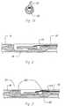
- Referring now to the drawings, wherein like numerals indicate like parts, and initially to Figs. 1 and 1a, there will be seen a preferred embodiment of the sensor and guide wire assembly. As shown in Figs. 1 and 1a, the assembly generally comprises a
core wire 1, atube 2 in which thecore wire 1 at least partially is inserted, at least onecoil sensor element 12 attached to thecore wire 1 in a suitable mounting arrangement (to be described below). Thecore wire 1 has anenlarged portion 10. The cross section of theenlarged portion 10 has a major dimension that is larger than the major dimension of the cross sections of the remaining portions of thecore wire 1. In the case of a cylindrical core wire, the major dimension of theenlarged portion 10 is represented by the diameter of the circular cross section of the core wire, and that diameter is larger than the diameters of the remaining portions of the core wire. In the embodiment of Figs. 1 and 1a, the distal end of thecore wire 1, anchored in tip 7 of the assembly, has a smaller diameter than the diameter of theenlarged portion 10. - For illustrative purposes, the assembly has been divided into five sections, A-E, in Figs. 1 and 1a. Section A is the most distal portion of the assembly, i.e., that portion which is going to be inserted farthest into the vessel, and section E is the most proximal portion. Section E is provided with a male
proximal connector 20. In a preferred embodiment, section A is about 10-50 mm; section B is about 0.5-5 mm; section C is about 200-400 mm; section D is about 500-3500 mm; and section E is about 5-50 mm in length. The diameter of the guide wire varies between 0.25-2 mm. For use in coronary arteries, the diameter is normally 0.35 mm. - Section A preferably includes a
radiopaque coil 8, which is made of, for example, platinum or a platinum alloy, usable as a position marker during manipulation of the guide wire. At the very distal end of section A, there is provided a tip 7 having a hemispherical outer shape. The tip 7 may be attached to thecoil 8 by welding, soldering, or other suitable attachment methods. - The
core wire 1 has anenlarged portion 10 in section B. In the transition area between sections A and B, the proximal end of thecoil 8 is attached to theenlarged portion 10 of thecore wire 1 with glue, solder, or another suitable adhesive. Alternatively, thecoil 8 may be threaded onto the enlarged portion 10 (further details of the coil attachment will be given below). Anothercoil 15 is attached to a proximal end of theenlarged portion 10. Thecoil 15 extends over section C for providing flexibility in this region of thecore wire 1 and protection of thecables 14. - In the
enlarged portion 10, there is provided a sensor receptacle, preferably aslot 11, in which asensor 12 is mounted. The sensor may, for example, be a pressure sensor. Theenlarged portion 10 of thecore wire 1, in which thesensor 12 is mounted, decreases the stress exerted on thesensor 12 during sharp vessel turns. Moreover, theenlarged portion 10, by virtue of the provision of theslot 11, protects thesensor 12 from being mechanically destroyed during handling of thecore wire 1 or by contact with the vessel wall. The side walls inside theslot 11 should extend a certain distance above the upper surface of thesensor 12 in order to provide the protection desired. - The
enlarged portion 10 is preferably made by removing material from a metal wire having the nominal diameter of the enlarged portion so as to form smaller diameter segments extending distally and proximally of the enlarged portion. The machining of the wire can be made by various methods, centerless grinding being a preferred method, although other methods are possible. - Alternatively, the enlarged portion may be made by attaching a short tube segment on a core wire, for example, by soldering. A depression forming a mounting receptacle for the sensor may be made by spark machining. In this way, the overall structure will closely resemble the embodiment of Figs. 1 and 1a.
- Attached to the
sensor 12 aresignal transmitting cables 14, the number of which may vary, depending on the design of the sensor. In the embodiment shown, there are three cables (see Fig. 1b). Thesecables 14 are, for example, attached to thesensor 12 on bond pads (not shown) by bonding or by another suitable technique. The points of attachment of thecables 14 to thesensor 12 are preferably protected from the environment, i.e., from blood or other body fluids. Normally, this may be achieved by filling theslot 11 with silicon rubber or other polymer material to provide adequate protection from such fluids and other environmental impact. - The
slot 11 preferably has a width and depth dimension of approximately 50-250 µm and a length dimension of approximately is 50-2500 µm. - As can be seen in Fig. 1a, the
slot 11 extends in the proximal direction of thecore wire 1 to transform into ashallower recess 16 in which thecables 14 rest. Theslot 11 andrecess 16 are configured so that thecoil 15 does not interfere with or damage thedelicate cables 14 when thecoil 15 is attached. The relativelyshallow recess 16 is defined by ashelf 17 machined in thecore wire 1. The main reason for thisshelf 17 is that, if theslot 11 were to extend further in the proximal direction of thecore wire 1 than the distal edge of the relativelyshallow recess 16, the strength of theenlarged portion 10 of thecore wire 1 would be inadequate at the transition between sections B and C. - A
recess 18, similar torecess 16, is formed in thecore wire 1 at the transition between sections C and D, where thecore wire 1 is inserted in thetube 2. Thisrecess 18 is provided for the protection of thecables 14, so that they will not be damaged, for example, during assembly. - In the shown embodiment, the
core wire 1 extends into thetube 2 only over a relatively short distance in section D. It may be glued in place in thetube 2, although other methods of attachment are possible. However, it is also conceivable, and indeed may be preferable, to let thecore wire 1 extend over the entire length of the assembly, all the way up to theproximal connector 20. In this case, it may be necessary to join two pieces to form the core wire, since it may be unfavorable to form a long core wire with enlarged portions via the grinding method. Simply too much metal working would be necessary. - The distal end of the
enlarged portion 10, located in section A, preferably is tapered to form a slightly conical extension and functions as an attachment surface for thecoil 8. This extension is narrowed down to form a thin wire, which is anchored in the tip 7 of the assembly. The successive tapering of thecore wire 1 in section A towards the tip results in a front portion of the guide wire assembly that becomes progressively more flexible nearing the tip 7. This tapering may be obtained by grinding of the metal core wire. It should be noted that the attachment surface of the core wire need not be conical, but rather may be formed as a flattened portion to which the coil and tip may attach. - The
coils - In Fig. 2, an embodiment of the invention is shown wherein a further depression or
recess 19 has been formed in the bottom of theenlarged portion 10. The purpose of thisrecess 19 is to ensure that the distal, pressure sensitive part of the sensor will not experience any mechanical stress, which otherwise could be induced by stress in theenlarged portion 10 if thecore wire 1 were bent in the region of sections A-B-C, especially at the transitions between these sections. - As can be clearly seen in Figs. 1 and 2, the
enlarged portion 10 has an outer diameter that is essentially equal to the outer diameter of thecoils - As indicated above, there are several alternative methods of attaching the
coils enlarged portion 10 and to thetube 2, respectively. Also, there are various alternatives for attachment of thecore wire 1 to thetube 2. Some of these alternatives will now be described. - In Fig. 3, an embodiment is shown wherein the
coils enlarged portion 10. To this end, theenlarged portion 10 has been made to have distal andproximal extensions enlarged portion 10. Thethreads 100 are most conveniently made by EDM or micromachining. The number of threads is not critical, but 4-10 threads would be suitable. - In Fig. 4a, there are provided distal and
proximal extensions enlarged portion 10. Thecoils extensions extensions enlarged portion 10. - In Fig. 4b, the
enlarged portion 10 has been made with a smaller diameter over a larger fraction of its length, to form aproximal extension 53, such that theproximal coil 15, when attached thereto, covers a large fraction (as much as up to 2/3 or more) of theslot 11. Thereby, further protection for thesensor 12 is provided. - Also in these embodiments, the
slot 11 extends in the proximal direction so as to form arecess 16, in which thecables 14 may rest for protective purposes. - In Figs. 5a and 5b, an embodiment is shown wherein the
slot 11 extends all the way through theenlarged portion 10. In order to fix thesensor 12 in position inside theslot 11, theslot 11 is filled with a material such as silicon rubber or other material. The silicon has a protective effect. Also, in this embodiment, there is provided arecess 16 for accommodating thecables 14. - A particular feature of the
enlarged portion 10 of Figs. 5a and 5b is itstapered extensions 61 and 62, respectively, in distal and proximal directions. As indicated in the introduction, the provision of a protective tube for the sensor tends to cause manufacturing problems because mismatches between the coil and the tube may occur. The quality of the joints also varies considerably, yielding variations in the flexibility in the sensor region from one assembly to another. By forming theenlarged portion 10 with taperedsurfaces 61, 62, it becomes relatively easy to mount thecoils coils enlarged portion 10 to their mounting positions. - In Fig. 6, it is shown how the
core wire 1 can be secured in the tip 7 by attaching aseparate wire 200 to thecore wire 1 and anchoring it in the tip 7. - Now a number of possibilities of attaching the
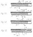
core wire 1 andcoil 15 to thetube 2 will be described with reference to Figs. 7-13. In all these figures, thecore wire 1 is shown to extend only a short distance into thetube 2. However, it may be desirable, from a point of view of providing enough bending strength, to let thecore wire 1 extend even all the way through thetube 2 to its proximal end, where a connector (20 as shown in Fig. 1) is provided. - Fig. 7 illustrates an embodiment wherein the
core wire 1 has been enclosed in, or inserted in, atube segment 24 that has an outer diameter corresponding to or being slightly smaller than the inner diameter of thetube 2, in order to obtain a tight fit between thecore wire 1 and thetube 2. Alongitudinal recess 26 is made in thetube segment 24 for the accommodation of thecables 14. The cross section of thetube segment 24 may resemble a C-shape, where thecables 14 run in the opening of the "C." The material of thetube segment 24 is preferably, but not limited to, polyimide. The material thickness of thetube 2 is preferably substantially the same as the diameter of the wire making up thecoil 15. Thereby, the outer diameter of thecoil 15 will be essentially equal to the outer diameter of thetube 2. The part of thetube segment 24 that extends out from anedge 32 of thetube 2 functions as a mount for thecoil 15. Thecoil 15 is pushed onto thetube segment 24 and secured thereto by gluing, welding, soldering, or any other suitable technique. - In Fig. 8, a tight fit between
core wire 1 andtube 2 is obtained by increasing the diameter of thecore wire 1 to form acore wire segment 27, the diameter of which corresponds to or is slightly smaller than the inner diameter of thetube 2. For accommodation of thecables 14, arecess 28 is made in thecore wire segment 27 by grinding or other machining methods, or some other suitable method. Thecore wire segment 27 extends out from anedge 32 of thetube 2 to provide a mounting site for thecoil 15, similar to the embodiment of Fig. 7. - Fig. 9 shows an embodiment, similar to the embodiment of Fig. 8, the difference being that, instead of providing a recess, core wire material has been removed to obtain a planar surface defining a
shelf 30. Theshelf 30 provides a space for accommodating saidcables 14. Whereas the windings of thecoil 15 are not visible along the length of therecess 28 from the coil's point of attachment to thetube 2 to a distal end of therecess 28, indicating that the material of theenlarged portion 27 blocks the coil windings from view, the coil windings are visible in the same region in Fig. 9, which illustrates aplanar shelf 30 instead of arecess 28. Thecoil 15 is attached to thecore wire segment 27, as in Fig. 8. - Fig. 10 illustrates an alternative attachment of the
coil 15 to what is disclosed in Fig. 8. Here, thecore wire segment 27 has been provided withthreads 34 in which thecoil windings 36 may be accommodated. Threading in this way may of course be supplemented with gluing or soldering or the like. - Fig. 11 illustrates an embodiment wherein the
tube 2 has been machined at its distal end such that a spiral likestructure 38 is obtained. Thecore wire segment 27 of thecore wire 1 is provided withthreads 39, adapted to cooperate with the spiral likestructure 38, to form an engagement between thetube 2 andcore wire 1. Thecoil 15 is attached to the non-threaded part of thecore wire segment 27, the non-threaded portion forming a mountingsite 40 for thecoil 15. - Fig. 12 is a further development of the embodiment of Fig. 11, wherein both the
coil 15 and thetube 2 are threaded ontothreads 39 of thecore wire segment 27. Of course, the attachment of thecoil 15 and thethreads 39 of thecore wire segment 27 to thetube 2 can be supplemented with glue or solder. - In the embodiment of Fig. 13, the distal end of the
tube 2 has a smaller outer diameter and less thickness than a remaining portion of thetube 2 so that the distal end may provide a mountingsite 42 for thecoil 15.
Claims (14)
- A sensor and guide wire assembly, comprisinga core wire (1) having a distal end, a proximal end, and an enlarged portion (10) at the distal end, said enlarged portion being provided with a sensor mounting member in the form of a slot (11);a sensor (12) mounted in said sensor mounting member of said enlarged portion (10) of said core wire (1);
characterized in that
said mounting member comprises an essentially cylindrical member, said slot (11) being formed therein, and adapted to house said sensor, andin that
the side walls inside the slot (11) extend a certain distance above the upper surface of the sensor (12) in order to provide adequate protection of said sensor from mechanical interference. - The sensor and guide wire assembly as recited in claim 1, wherein the slot (11) has a width and depth dimension in the range 50-250 µm, and a length dimension in the range 50-2500 µm.
- The sensor and guide wire assembly as recited in claim 1, wherein said sensor (12) is secured in place by embedding said sensor in a soft material selected from the group consisting of silicon rubber, latex, and other polymer materials.
- The sensor and guide wire assembly as recited in claim 1, wherein a further depression (19) has been formed in the bottom of the enlarged portion (10), beneath the distal end of the sensor (12), to ensure that the distal, pressure sensitive part of the sensor will not experience any mechanical stress.
- The sensor and guide wire assembly as recited in claim 1, wherein said slot (11) in which said sensor is mounted extends through said enlarged portion.
- The sensor and guide wire assembly as recited in claim 1, comprising a tube (2) enclosing said core wire (1) over at least a fraction of a length of said core wire such that said core wire (1) extends out from a distal end of said tube (2), said tube being configured to enable said sensor and guide wire assembly to be inserted into an artery and to be passed to a measurement site inside a body.
- The sensor and guide wire assembly as recited in claim 6, comprising wiring (14) extending from said sensor (12) through at least a portion of said tube (2) in a direction toward a proximal end of said tube; and
a tube segment (24) having an outer diameter essentially the same as an inner diameter of said tube, said tube segment being positioned between said core wire (1) and said tube (2) in an interference fit with said tube to secure said core wire in place in said tube, and said tube segment being configured to allow passage of said wiring through said portion of said tube. - The sensor and guide wire assembly as recited in claim 7, wherein a portion of said tube segment (24) extends out from said distal end of said tube, and said sensor and guide wire assembly further comprises a coil (15) mounted to said portion of said tube segment extending out from said distal end of said tube, said tube segment having an outer diameter essentially equal to an outer diameter of said tube (2).
- The sensor and guide wire assembly as recited in claim 6, wherein said core wire is mounted to said tube in an interference fit such that an outer diameter of said core wire is essentially equal to an inner diameter of said tube.
- The sensor and core guide assembly as recited in any preceding claim, wherein said core wire includes a longitudinal recess (28) therein for accommodating said wiring.
- The sensor and guide wire assembly as recited in any of claims 1-10, wherein said core wire includes a planar surface (30) for accommodating said wiring.
- The sensor and guide wire assembly as recited in any of claims 1-10, further comprising a coil (8) mounted to a portion of said core wire extending out from a distal end of said tube.
- The sensor and guide wire assembly as recited in claim 6, wherein said core wire is threadedly engaged to said tube, said core wire including external threads (39) that are complementary to a spiral-like structure formed at said distal end of said tube such that said spiral-like structure of said tube threadedly engages at least some of said threads of said core wire.
- The sensor and guide wire assembly as recited in claim 14, further comprising a coil having coil windings threadedly engaging distal ones of said threads (39) of said core wire.
Applications Claiming Priority (5)
| Application Number | Priority Date | Filing Date | Title |
|---|---|---|---|
| US11381098P | 1998-12-23 | 1998-12-23 | |
| US113810P | 1998-12-23 | ||
| US09/349,980US6142958A (en) | 1998-12-23 | 1999-07-09 | Sensor and guide wire assembly |
| US349980 | 1999-07-09 | ||
| EP99965684AEP1165171B1 (en) | 1998-12-23 | 1999-12-22 | Sensor and guide wire assembly |
Related Parent Applications (1)
| Application Number | Title | Priority Date | Filing Date |
|---|---|---|---|
| EP99965684ADivisionEP1165171B1 (en) | 1998-12-23 | 1999-12-22 | Sensor and guide wire assembly |
Publications (2)
| Publication Number | Publication Date |
|---|---|
| EP1479407A1 EP1479407A1 (en) | 2004-11-24 |
| EP1479407B1true EP1479407B1 (en) | 2006-03-01 |
Family
ID=33101782
Family Applications (1)
| Application Number | Title | Priority Date | Filing Date |
|---|---|---|---|
| EP04019652AExpired - LifetimeEP1479407B1 (en) | 1998-12-23 | 1999-12-22 | Sensor and guide wire assembly |
Country Status (1)
| Country | Link |
|---|---|
| EP (1) | EP1479407B1 (en) |
Cited By (3)
| Publication number | Priority date | Publication date | Assignee | Title |
|---|---|---|---|---|
| US7967761B2 (en) | 2006-12-01 | 2011-06-28 | Radi Medical Systems Ab | Sensor and guide wire assembly |
| US10314541B2 (en) | 2010-09-29 | 2019-06-11 | St. Jude Medical Coordination Center Bvba | Sensor guide wire |
| US10792473B2 (en) | 2016-03-16 | 2020-10-06 | St. Jude Medical Coordination Center Bvba | Core wire having a flattened portion to provide preferential bending |
Families Citing this family (22)
| Publication number | Priority date | Publication date | Assignee | Title |
|---|---|---|---|---|
| EP1927316B1 (en)* | 2006-12-01 | 2012-10-17 | Radi Medical Systems Ab | Sensor and guide wire assembly |
| CN103328033B (en) | 2010-11-09 | 2016-05-18 | 奥普森斯公司 | There is the seal wire of internal pressure sensor |
| EP2887863B1 (en) | 2012-08-27 | 2019-11-27 | Boston Scientific Scimed, Inc. | Pressure-sensing medical device system |
| EP2890291B1 (en)* | 2012-08-31 | 2020-06-24 | Volcano Corporation | Mounting structures for components of intravascular devices |
| US20140081244A1 (en)* | 2012-09-17 | 2014-03-20 | Boston Scientific Scimed, Inc. | Pressure sensing guidewire |
| CN105209102B (en) | 2013-03-15 | 2018-10-02 | 波士顿科学国际有限公司 | Pressure-sensing seal wire |
| CN105682544B (en) | 2013-05-22 | 2019-09-24 | 波士顿科学国际有限公司 | Pressure detecting godet system including optical connector optical cable |
| WO2015013646A1 (en) | 2013-07-26 | 2015-01-29 | Boston Scientific Scimed, Inc. | Ffr sensor head design that minimizes stress induced pressure offsets |
| US10835182B2 (en) | 2013-08-14 | 2020-11-17 | Boston Scientific Scimed, Inc. | Medical device systems including an optical fiber with a tapered core |
| WO2015057518A1 (en) | 2013-10-14 | 2015-04-23 | Boston Scientific Scimed, Inc. | Pressure sensing guidewire and methods for calculating fractional flow reserve |
| US10932679B2 (en) | 2014-03-18 | 2021-03-02 | Boston Scientific Scimed, Inc. | Pressure sensing guidewires and methods of use |
| EP3132296B1 (en) | 2014-04-17 | 2023-01-04 | Boston Scientific Scimed, Inc. | Self-cleaning optical connector |
| WO2015187385A1 (en) | 2014-06-04 | 2015-12-10 | Boston Scientific Scimed, Inc. | Pressure sensing guidewire systems with reduced pressure offsets |
| WO2016019207A1 (en) | 2014-08-01 | 2016-02-04 | Boston Scientific Scimed, Inc. | Pressure sensing guidewires |
| CN107405089B (en) | 2014-12-05 | 2020-09-04 | 波士顿科学国际有限公司 | Pressure sensing guide wire |
| EP3419514B1 (en) | 2016-02-23 | 2023-08-23 | Boston Scientific Scimed, Inc. | Pressure sensing guidewire systems including an optical connector cable |
| CN116327157B (en) | 2017-08-03 | 2025-09-30 | 波士顿科学国际有限公司 | Methods for assessing fractional flow reserve |
| US11311196B2 (en) | 2018-02-23 | 2022-04-26 | Boston Scientific Scimed, Inc. | Methods for assessing a vessel with sequential physiological measurements |
| EP3768156B1 (en) | 2018-03-23 | 2023-09-20 | Boston Scientific Scimed, Inc. | Medical device with pressure sensor |
| WO2019195721A1 (en) | 2018-04-06 | 2019-10-10 | Boston Scientific Scimed, Inc. | Medical device with pressure sensor |
| CN119564167A (en) | 2018-04-18 | 2025-03-07 | 波士顿科学国际有限公司 | System for vascular assessment using continuous physiological measurements |
| US12087000B2 (en) | 2021-03-05 | 2024-09-10 | Boston Scientific Scimed, Inc. | Systems and methods for vascular image co-registration |
Family Cites Families (3)
| Publication number | Priority date | Publication date | Assignee | Title |
|---|---|---|---|---|
| SE460396B (en)* | 1988-07-29 | 1989-10-09 | Radisensor Ab | MINIATURIZED SENSOR DEVICE FOR SEATING PHYSIOLOGICAL PRESSURE IN VIVO |
| SE506135C2 (en)* | 1990-07-11 | 1997-11-17 | Radi Medical Systems | Sensor and conductor construction |
| DE69534748T2 (en)* | 1994-09-02 | 2006-11-02 | Volcano Corp. (n.d, Ges.d.Staates Delaware), Rancho Cordova | ULTRAMINIATUR PRESSURE SENSOR AND GUIDE WIRE THEREFORE |
- 1999
- 1999-12-22EPEP04019652Apatent/EP1479407B1/ennot_activeExpired - Lifetime
Cited By (3)
| Publication number | Priority date | Publication date | Assignee | Title |
|---|---|---|---|---|
| US7967761B2 (en) | 2006-12-01 | 2011-06-28 | Radi Medical Systems Ab | Sensor and guide wire assembly |
| US10314541B2 (en) | 2010-09-29 | 2019-06-11 | St. Jude Medical Coordination Center Bvba | Sensor guide wire |
| US10792473B2 (en) | 2016-03-16 | 2020-10-06 | St. Jude Medical Coordination Center Bvba | Core wire having a flattened portion to provide preferential bending |
Also Published As
| Publication number | Publication date |
|---|---|
| EP1479407A1 (en) | 2004-11-24 |
Similar Documents
| Publication | Publication Date | Title |
|---|---|---|
| EP1165171B1 (en) | Sensor and guide wire assembly | |
| EP1479407B1 (en) | Sensor and guide wire assembly | |
| USRE35648E (en) | Sensor guide construction and use thereof | |
| US5085223A (en) | Miniaturized pressure sensor having means for protection of diaphragm | |
| JP6321168B2 (en) | SENSOR MOUNTING ASSEMBLY FOR GUIDEWIRE WITH SENSOR AND RELATED DEVICES, SYSTEMS AND METHODS | |
| US5267574A (en) | Guidewire with spring and a heat shrinkable connection | |
| CN106456018B (en) | Pressure measurement catheter with reduced error from bending stress | |
| EP2209419B1 (en) | Sensor guide wire | |
| EP1684628B1 (en) | Sensor and guide wire assembly | |
| EP1493381B1 (en) | Sensor and guide wire assembly | |
| JP2945901B2 (en) | Induction wire | |
| US5429617A (en) | Radiopaque tip marker for alignment of a catheter within a body | |
| US20130296718A1 (en) | Tube and sensor guide wire comprising tube | |
| EP2211701A1 (en) | Sensor guide wire with micro-cable winding | |
| US20100318000A1 (en) | Sensor guide wire | |
| US9949647B2 (en) | Sensor and guide wire assembly | |
| JP4252007B2 (en) | Male connector for guide wire | |
| JP2004337606A (en) | Core wire and sensor guide wire assembly | |
| AU2004202152B2 (en) | Sensor and guide wire assembly | |
| EP1604702A1 (en) | A vascular guidewire for venous valvular angioplasty | |
| JPS598946A (en) | Endoscope treating coil |
Legal Events
| Date | Code | Title | Description |
|---|---|---|---|
| PUAI | Public reference made under article 153(3) epc to a published international application that has entered the european phase | Free format text:ORIGINAL CODE: 0009012 | |
| AC | Divisional application: reference to earlier application | Ref document number:1165171 Country of ref document:EP Kind code of ref document:P | |
| AK | Designated contracting states | Kind code of ref document:A1 Designated state(s):AT BE CH CY DE DK ES FI FR GB GR IE IT LI LU MC NL PT SE | |
| RIN1 | Information on inventor provided before grant (corrected) | Inventor name:VON MALMBORG, PER Inventor name:BENKOWSKI, PER Inventor name:HAMMARSTROEM, OLA Inventor name:TENERZ, LARS | |
| 17P | Request for examination filed | Effective date:20050502 | |
| GRAP | Despatch of communication of intention to grant a patent | Free format text:ORIGINAL CODE: EPIDOSNIGR1 | |
| AKX | Designation fees paid | Designated state(s):AT BE CH CY DE DK ES FI FR GB GR IE IT LI LU MC NL PT SE | |
| GRAS | Grant fee paid | Free format text:ORIGINAL CODE: EPIDOSNIGR3 | |
| GRAA | (expected) grant | Free format text:ORIGINAL CODE: 0009210 | |
| AC | Divisional application: reference to earlier application | Ref document number:1165171 Country of ref document:EP Kind code of ref document:P | |
| AK | Designated contracting states | Kind code of ref document:B1 Designated state(s):AT BE CH CY DE DK ES FI FR GB GR IE IT LI LU MC NL PT SE | |
| PG25 | Lapsed in a contracting state [announced via postgrant information from national office to epo] | Ref country code:IT Free format text:LAPSE BECAUSE OF FAILURE TO SUBMIT A TRANSLATION OF THE DESCRIPTION OR TO PAY THE FEE WITHIN THE PRESCRIBED TIME-LIMIT;WARNING: LAPSES OF ITALIAN PATENTS WITH EFFECTIVE DATE BEFORE 2007 MAY HAVE OCCURRED AT ANY TIME BEFORE 2007. THE CORRECT EFFECTIVE DATE MAY BE DIFFERENT FROM THE ONE RECORDED. Effective date:20060301 Ref country code:FI Free format text:LAPSE BECAUSE OF FAILURE TO SUBMIT A TRANSLATION OF THE DESCRIPTION OR TO PAY THE FEE WITHIN THE PRESCRIBED TIME-LIMIT Effective date:20060301 Ref country code:BE Free format text:LAPSE BECAUSE OF FAILURE TO SUBMIT A TRANSLATION OF THE DESCRIPTION OR TO PAY THE FEE WITHIN THE PRESCRIBED TIME-LIMIT Effective date:20060301 Ref country code:AT Free format text:LAPSE BECAUSE OF FAILURE TO SUBMIT A TRANSLATION OF THE DESCRIPTION OR TO PAY THE FEE WITHIN THE PRESCRIBED TIME-LIMIT Effective date:20060301 Ref country code:CH Free format text:LAPSE BECAUSE OF FAILURE TO SUBMIT A TRANSLATION OF THE DESCRIPTION OR TO PAY THE FEE WITHIN THE PRESCRIBED TIME-LIMIT Effective date:20060301 Ref country code:NL Free format text:LAPSE BECAUSE OF FAILURE TO SUBMIT A TRANSLATION OF THE DESCRIPTION OR TO PAY THE FEE WITHIN THE PRESCRIBED TIME-LIMIT Effective date:20060301 Ref country code:LI Free format text:LAPSE BECAUSE OF FAILURE TO SUBMIT A TRANSLATION OF THE DESCRIPTION OR TO PAY THE FEE WITHIN THE PRESCRIBED TIME-LIMIT Effective date:20060301 | |
| REG | Reference to a national code | Ref country code:GB Ref legal event code:FG4D | |
| RIN1 | Information on inventor provided before grant (corrected) | Inventor name:BENKOWSKI, PER Inventor name:VON MALMBORG, PER Inventor name:TENERZ, LARS Inventor name:HAMMARSTROEM, OLA | |
| REG | Reference to a national code | Ref country code:CH Ref legal event code:EP | |
| REG | Reference to a national code | Ref country code:IE Ref legal event code:FG4D | |
| REF | Corresponds to: | Ref document number:69930022 Country of ref document:DE Date of ref document:20060427 Kind code of ref document:P | |
| PG25 | Lapsed in a contracting state [announced via postgrant information from national office to epo] | Ref country code:DK Free format text:LAPSE BECAUSE OF FAILURE TO SUBMIT A TRANSLATION OF THE DESCRIPTION OR TO PAY THE FEE WITHIN THE PRESCRIBED TIME-LIMIT Effective date:20060601 | |
| PG25 | Lapsed in a contracting state [announced via postgrant information from national office to epo] | Ref country code:ES Free format text:LAPSE BECAUSE OF FAILURE TO SUBMIT A TRANSLATION OF THE DESCRIPTION OR TO PAY THE FEE WITHIN THE PRESCRIBED TIME-LIMIT Effective date:20060612 | |
| REG | Reference to a national code | Ref country code:SE Ref legal event code:TRGR | |
| PG25 | Lapsed in a contracting state [announced via postgrant information from national office to epo] | Ref country code:PT Free format text:LAPSE BECAUSE OF FAILURE TO SUBMIT A TRANSLATION OF THE DESCRIPTION OR TO PAY THE FEE WITHIN THE PRESCRIBED TIME-LIMIT Effective date:20060801 | |
| NLV1 | Nl: lapsed or annulled due to failure to fulfill the requirements of art. 29p and 29m of the patents act | ||
| REG | Reference to a national code | Ref country code:CH Ref legal event code:PL | |
| ET | Fr: translation filed | ||
| PG25 | Lapsed in a contracting state [announced via postgrant information from national office to epo] | Ref country code:IE Free format text:LAPSE BECAUSE OF NON-PAYMENT OF DUE FEES Effective date:20061222 | |
| PG25 | Lapsed in a contracting state [announced via postgrant information from national office to epo] | Ref country code:MC Free format text:LAPSE BECAUSE OF NON-PAYMENT OF DUE FEES Effective date:20061231 | |
| PLBE | No opposition filed within time limit | Free format text:ORIGINAL CODE: 0009261 | |
| STAA | Information on the status of an ep patent application or granted ep patent | Free format text:STATUS: NO OPPOSITION FILED WITHIN TIME LIMIT | |
| 26N | No opposition filed | Effective date:20061204 | |
| PG25 | Lapsed in a contracting state [announced via postgrant information from national office to epo] | Ref country code:GR Free format text:LAPSE BECAUSE OF FAILURE TO SUBMIT A TRANSLATION OF THE DESCRIPTION OR TO PAY THE FEE WITHIN THE PRESCRIBED TIME-LIMIT Effective date:20060602 | |
| PG25 | Lapsed in a contracting state [announced via postgrant information from national office to epo] | Ref country code:LU Free format text:LAPSE BECAUSE OF NON-PAYMENT OF DUE FEES Effective date:20061222 | |
| PG25 | Lapsed in a contracting state [announced via postgrant information from national office to epo] | Ref country code:CY Free format text:LAPSE BECAUSE OF FAILURE TO SUBMIT A TRANSLATION OF THE DESCRIPTION OR TO PAY THE FEE WITHIN THE PRESCRIBED TIME-LIMIT Effective date:20060301 | |
| REG | Reference to a national code | Ref country code:DE Ref legal event code:R082 Ref document number:69930022 Country of ref document:DE Representative=s name:HOFFMANN - EITLE PATENT- UND RECHTSANWAELTE PA, DE Ref country code:DE Ref legal event code:R081 Ref document number:69930022 Country of ref document:DE Owner name:ST. JUDE MEDICAL COORDINATION CENTER BVBA, BE Free format text:FORMER OWNER: RADI MEDICAL SYSTEMS AB, UPPSALA, SE | |
| REG | Reference to a national code | Ref country code:GB Ref legal event code:732E Free format text:REGISTERED BETWEEN 20150827 AND 20150902 | |
| REG | Reference to a national code | Ref country code:FR Ref legal event code:PLFP Year of fee payment:17 | |
| REG | Reference to a national code | Ref country code:FR Ref legal event code:TP Owner name:ST. JUDE MEDICAL COORDINATION CENTER BVBA, BE Effective date:20160113 | |
| REG | Reference to a national code | Ref country code:FR Ref legal event code:PLFP Year of fee payment:18 | |
| REG | Reference to a national code | Ref country code:FR Ref legal event code:PLFP Year of fee payment:19 | |
| PGFP | Annual fee paid to national office [announced via postgrant information from national office to epo] | Ref country code:FR Payment date:20171227 Year of fee payment:19 | |
| PGFP | Annual fee paid to national office [announced via postgrant information from national office to epo] | Ref country code:GB Payment date:20171227 Year of fee payment:19 Ref country code:SE Payment date:20171229 Year of fee payment:19 | |
| PGFP | Annual fee paid to national office [announced via postgrant information from national office to epo] | Ref country code:DE Payment date:20171229 Year of fee payment:19 | |
| REG | Reference to a national code | Ref country code:DE Ref legal event code:R119 Ref document number:69930022 Country of ref document:DE | |
| REG | Reference to a national code | Ref country code:SE Ref legal event code:EUG | |
| PG25 | Lapsed in a contracting state [announced via postgrant information from national office to epo] | Ref country code:SE Free format text:LAPSE BECAUSE OF NON-PAYMENT OF DUE FEES Effective date:20181223 | |
| GBPC | Gb: european patent ceased through non-payment of renewal fee | Effective date:20181222 | |
| PG25 | Lapsed in a contracting state [announced via postgrant information from national office to epo] | Ref country code:DE Free format text:LAPSE BECAUSE OF NON-PAYMENT OF DUE FEES Effective date:20190702 Ref country code:FR Free format text:LAPSE BECAUSE OF NON-PAYMENT OF DUE FEES Effective date:20181231 | |
| PG25 | Lapsed in a contracting state [announced via postgrant information from national office to epo] | Ref country code:GB Free format text:LAPSE BECAUSE OF NON-PAYMENT OF DUE FEES Effective date:20181222 |