EP1476617B1 - Shingle system - Google Patents
Shingle systemDownload PDFInfo
- Publication number
- EP1476617B1 EP1476617B1EP03709060AEP03709060AEP1476617B1EP 1476617 B1EP1476617 B1EP 1476617B1EP 03709060 AEP03709060 AEP 03709060AEP 03709060 AEP03709060 AEP 03709060AEP 1476617 B1EP1476617 B1EP 1476617B1
- Authority
- EP
- European Patent Office
- Prior art keywords
- shingle
- base
- edge
- barrier
- assemblies
- Prior art date
- Legal status (The legal status is an assumption and is not a legal conclusion. Google has not performed a legal analysis and makes no representation as to the accuracy of the status listed.)
- Expired - Lifetime
Links
Images


Classifications
- H—ELECTRICITY
- H10—SEMICONDUCTOR DEVICES; ELECTRIC SOLID-STATE DEVICES NOT OTHERWISE PROVIDED FOR
- H10F—INORGANIC SEMICONDUCTOR DEVICES SENSITIVE TO INFRARED RADIATION, LIGHT, ELECTROMAGNETIC RADIATION OF SHORTER WAVELENGTH OR CORPUSCULAR RADIATION
- H10F77/00—Constructional details of devices covered by this subclass
- H10F77/60—Arrangements for cooling, heating, ventilating or compensating for temperature fluctuations
- H10F77/63—Arrangements for cooling directly associated or integrated with photovoltaic cells, e.g. heat sinks directly associated with the photovoltaic cells or integrated Peltier elements for active cooling
- H—ELECTRICITY
- H02—GENERATION; CONVERSION OR DISTRIBUTION OF ELECTRIC POWER
- H02S—GENERATION OF ELECTRIC POWER BY CONVERSION OF INFRARED RADIATION, VISIBLE LIGHT OR ULTRAVIOLET LIGHT, e.g. USING PHOTOVOLTAIC [PV] MODULES
- H02S20/00—Supporting structures for PV modules
- H02S20/20—Supporting structures directly fixed to an immovable object
- H02S20/22—Supporting structures directly fixed to an immovable object specially adapted for buildings
- H02S20/23—Supporting structures directly fixed to an immovable object specially adapted for buildings specially adapted for roof structures
- F—MECHANICAL ENGINEERING; LIGHTING; HEATING; WEAPONS; BLASTING
- F24—HEATING; RANGES; VENTILATING
- F24S—SOLAR HEAT COLLECTORS; SOLAR HEAT SYSTEMS
- F24S40/00—Safety or protection arrangements of solar heat collectors; Preventing malfunction of solar heat collectors
- F24S40/80—Accommodating differential expansion of solar collector elements
- F24S40/85—Arrangements for protecting solar collectors against adverse weather conditions
- Y—GENERAL TAGGING OF NEW TECHNOLOGICAL DEVELOPMENTS; GENERAL TAGGING OF CROSS-SECTIONAL TECHNOLOGIES SPANNING OVER SEVERAL SECTIONS OF THE IPC; TECHNICAL SUBJECTS COVERED BY FORMER USPC CROSS-REFERENCE ART COLLECTIONS [XRACs] AND DIGESTS
- Y02—TECHNOLOGIES OR APPLICATIONS FOR MITIGATION OR ADAPTATION AGAINST CLIMATE CHANGE
- Y02B—CLIMATE CHANGE MITIGATION TECHNOLOGIES RELATED TO BUILDINGS, e.g. HOUSING, HOUSE APPLIANCES OR RELATED END-USER APPLICATIONS
- Y02B10/00—Integration of renewable energy sources in buildings
- Y02B10/10—Photovoltaic [PV]
- Y—GENERAL TAGGING OF NEW TECHNOLOGICAL DEVELOPMENTS; GENERAL TAGGING OF CROSS-SECTIONAL TECHNOLOGIES SPANNING OVER SEVERAL SECTIONS OF THE IPC; TECHNICAL SUBJECTS COVERED BY FORMER USPC CROSS-REFERENCE ART COLLECTIONS [XRACs] AND DIGESTS
- Y02—TECHNOLOGIES OR APPLICATIONS FOR MITIGATION OR ADAPTATION AGAINST CLIMATE CHANGE
- Y02E—REDUCTION OF GREENHOUSE GAS [GHG] EMISSIONS, RELATED TO ENERGY GENERATION, TRANSMISSION OR DISTRIBUTION
- Y02E10/00—Energy generation through renewable energy sources
- Y02E10/50—Photovoltaic [PV] energy
Definitions
- the inventionrelates to a shingle system according to the generic clause of claim 1.
- a shingle systemis already known from US 5,613,337 .
- This documentshows roofing shingles and more particularly metal shingles having interlocking folding edges.
- roofing shinglescome in two primary types.
- a first typeis typically flat and is designed so that there is a generous amount of overlap between adjacent shingles to create weather resistant joints to help ensure weather tightness.
- This first, edge-overlapping typemay be flexible, such as the common composition or asphalt shingle, or it may be rigid, such as slate or some concrete shingles.
- a second type of roofing shinglehas interlocking edges to secure the edges to one another and to help create effectively weather resistant joints to provide the desired weather tightness.
- the interlocking edges of this second, edge-interlocking typemay, for example, have generally U-shaped edges creating lap joints, may have standing seam type of interlocking edges, or may have batten seam type of interlocking edges, or a combination thereon
- Shinglesmay be secured to the roofing substrate using, for example, adhesives or mechanical devices such as clips, which engage the edges of the shingles, and roofing nails, which secure the clips and/or the shingle itself to the roofing substrate.
- ATAS International, Inc. of Allentown, Pennsylvaniamanufactures various types of interlocking metal shingles, including shingles having interlocking edges along all four sides.
- Owens Corning of Toledo OHalso makes interlocking metal roofing panels sold under the trademark MiraVista®.
- PVphotovoltaic
- PV mounted integrally with the building roof as shinglesoperate at higher temperatures, causing a reduction in PV electrical output due to an inverse relationship between temperature and PV efficiency; 2) the same higher operating temperatures approach or exceed the upper limit of the warranted PV operating temperature (typically 80 degrees C) and serve to shorten the useful life of the PV shingle; 3) some products call for electrical connections between shingles to be made under the roof deck, requiring holes to be drilled through the roof deck which increases the likelihood of water leaks; 4) there has been poor aesthetic match ofPV shingles in conjunction with the non-PV areas of the roof; 5) some PV shingles have been limited to amorphous silicon PV technology, which suffer from a low operating efficiency; and 6) the value of the PV shingle has typically been limited to the electrical output of the PV plus the material value of displaced conventional shingles when the product displaces conventional shingles.
- a first aspect of the inventionis directed to a shingle system, for use on an inclined surface, comprising a plurality of shingle assemblies. At least some of the shingle assemblies include a water resistant base and a barrier, such as a PV module, secured to the base by a support to create the shingle assembly. The shingle assembly defines a venting region between the barrier and base for temperature regulation. Water resistant junctions are formed between the bases of adjacent shingle assemblies.
- the array of shingle assembliesmay include rows of shingle assemblies. The shingle assemblies of one row may be laterally offset from or laterally aligned with the shingle assemblies of an adjacent row.
- a second aspect of the inventionis directed to a shingle system, for use on an inclined surface, comprising rows of shingle assemblies.
- At least some of the shingle assembliesinclude a water resistant base and a barrier, such as a PV module, secured to the base by a support to create the shingle assembly.
- the shingle assemblydefines a venting region between the barrier and base for temperature regulation.
- the basecomprises a water barrier overlying an installation layer, the water barriers of one row overlapping the water interiors of adjacent row.
- a third aspect of the inventionis directed to a shingle assembly, for use on an inclined surface, including a base and a barrier mounted to the base.
- the baseincludes a waterproofing element having a width and a height, the width and height of the barrier being shorter than the width and height of the waterproofing element of the base, whereby water resistance is gained when portions of the base of one shingle overlap portions of the base of adjacent shingles.
- a primary advantagerelates to temperature regulation, the temperature regulation being achieved in part by the use of a venting region between the barrier and the base.
- the provision of a venting regionhelps reduce the temperature of the PV module, when the barrier comprises a PV module, which helps to increase the efficiency of the PV module over the efficiency of a PV module mounted to a support surface without a venting region.
- This reduction in temperature under typical summertime operating conditions in central California, such as Sacramento,has been found to be about 20°C, representing about a 10 percent increase in PV efficiency.
- This increase in efficiencyhelps to reduce the cost per unit energy for the system.
- the use of a venting regionalso helps to reduce the temperature of the support surface, typically the roof of a building.
- This reduction in temperaturecan result in very significant reductions in the air-conditioned system load due to a substantial reduction in heat gain through the roof.
- the calculated reduction in an air conditioning system load due to heat gain through the roof for a typical day in August in central Californiahas been calculated to be about 90 percent
- Further thermal benefitsmay be achieved through the use of a radiant barrier between the barrier and the base or by making the base a thermally insulating base. Energy savings are also increased when the barrier is a PV module used for the production of energy.
- the present inventionis suitable for both new construction and retrofit applications over existing roofing.
- retrofit applicationssuch as when an existing roof has clay or concrete tiles, it may be best to remove portions of the existing roofing tiles.
- Figure 1Ais a simplified representation of an array of PV shingle assemblies with the shingle assemblies of one row laterally offset from the shingle assemblies of an adjacent row;
- Figure 1Bis a simplified representation of an array of PV shingle assemblies with the shingle assemblies of one row laterally aligned with the shingle assemblies of an adjacent row;
- Figure 2is a simplified top isometric view of an edge-interlocking PV shingle assembly made according to the invention
- Figure 3is a simplified bottom isometric view of the PV module and supports of figure 2 ;
- Figure 4is a simplified view showing the interconnections between the U-shaped edge extensions of the bases of figure 2 ;
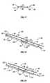
- Figure 5Ais a simplified side view showing the interconnections between adjacent rows of edge-interlocking PV shingle assemblies with the top and bottom edges of the PV module being generally aligned with the top and bottom edges of the base;
- Figure 5Bis a simplified side view showing the interconnections between adjacent rows of edge-interlocking PV shingle assemblies with the top edge of the PV module being setback inwardly of the top edge of the base and the bottom edge of the PV module overhanging the bottom edge of the base;
- Figure 5Cis a simplified side view showing the interconnections between adjacent rows of edge-interlocking PV shingle assemblies with the top edge of the PV module overhanging the top edge of the base and the bottom edge of the PV module being generally aligned with the bottom edge of the base;
- Figure 6illustrates the use of a recurved clip nailed to a support surface to secure interlocking edges of adjacent bases to the support surface
- Figure 7illustrates a batten seam including two upwardly extending edges secured to a support surface by fasteners, the seam covered by a resilient, generally U-shaped batten;
- Figure 8illustrates a standing seam type of edge joint with a clip engaging the interlocking edges, the clip being secured to the underlying support surface by a fastener
- Figure 9is a simplified side view illustrating three rows of edge-overlapping type of PV shingle assemblies including interlocking supports that extend beyond the top and bottom edges of the PV modules to engage the supports of the adjacent rows of PV modules;
- Figure 10illustrates the use of a stiffening bracket at the overlap between the PV modules of adjacent rows of PV assemblies
- Figure 11is a simplified side view illustrating the use of wind deflectors at the ridge of a building and at the edge of arrays of shingle assemblies to help promote proper airflow through the venting regions between the barriers and the bases of the shingle assemblies;
- Figure 12is a simplified isometric view of an edge-overlapping PV shingle assembly in which the base is a sheet of flexible, weather resistant material and the PV module is shown spaced apart from the bottom edge and the first lateral edge of the base by distances a and b;
- Figure 13illustrates how the flexible base of the shingle assembly of figure 12 may be folded over the PV module for shipping
- Figure 14illustrates a laterally offset array of edge-overlapping shingle assemblies
- Figure 15illustrates a laterally aligned array of edge-overlapping shingle assemblies
- Figure 16is a top plan view of an edge-overlapping shingle assembly illustrating certain electrical connectors
- Figure 17is a side view of the assembly of figure 16 taken along line 17-17;
- Figure 18is a simplified side view illustrating two rows of edge-overlapping type of PV shingle assemblies in which the base includes a water barrier mounted on top of a block of thermal insulation;
- Figure 19illustrates two rows of edge-overlapping type of PV shingle assemblies similar to figure 18 but with the PV modules in a skylight type of arrangement;
- Figure 20is a simplified representation of three rows of PV shingle assemblies
- Figure 21shows the array of figure 20 with the PV modules removed
- Figure 22is a large view of one of the bases of figure 21 showing a pair of bottom support members.
- Figure 23is a simplified bottom isometric view of a PV module of figure 20 showing a pair of clip-type top support members secured thereto.
- the present inventionis directed to shingle assemblies that can be mounted to inclined surfaces, such as the roof of a building, with the shingle assemblies in one row being either laterally offset or laterally aligned with the shingle assemblies in adjacent rows.
- Figure leaillustrates an array 10 of PV shingle assemblies 12 mounted to an inclined roof 14 with the rows 16 of shingle assemblies 12 laterally offset from one another.
- Figure 1Bshows an array 18 of PV shingle assemblies 12 also mounted to an inclined roof 14 with the rows 16 of shingle assemblies 12 laterally aligned with the shingle assemblies in an adjacent row. While the present invention will typically refer to the inclined support surface as roof 14, other inclined support surfaces, such as shed, deck, walkway covering, lattice structure, may also be used.
- Various embodiments of shingle assemblieswill be described below with like elements being referred to with like reference numerals.
- FIGS 2 and 3illustrate an edge-interlocking PV shingle assembly 12 comprising a base 20, a PV module 22 and a pair of supports 24 securing PV module 22 to the upper surface 26 of base 20.
- a venting region 28is defined between PV module 22 and base 20.
- the provision of venting region 28provides several advantages, including moderating the temperature of PV module 22 and reducing the amount of heat passing through roof 14 and into the underlying building.
- the efficiency of conventional PV modules 22can be increased by reducing the temperature of the PV modules. Reducing the amount of heat passing into the building by the use of PV modules 12 can lower the air conditioning load by a significant amount.
- base 20of a thermal insulating material (or attached to a thermal insulating material) and by using one or more low emissivity elements 30, typically at the inner surface 32 of PV module 22, at upper surface 26 of base 20 or at a position somewhere therebetween.
- low emissivity elements 30Three different positions for elements 30 are suggested in figure 5C .
- Shingle assembly 12uses PV module 22 as its barrier.
- PV module 22may be of a conventional, commonly available type, such as available from Shell Solar, BP Solar, Kyocera, Astropower, Sharp, Photowatt, or Uni-Solar, or an unconventional, specially made or adapted type of PV module.
- Base 20 of shingle assembly 12has conventional recurved edges to provide weatherproofing and interengagement between adjacent PV shingle assemblies.
- base 20has an upwardly curving top edge 36, a downwardly curving bottom edge 38, a downwardly curving first lateral edge 40 and an upwardly curving second lateral edge 42.
- Each of these recurved lateral edgesis generally U-shaped.
- Other conventional or unconventional interengageable edgesmay be used as well, and recurved edges 40 and 42 could be eliminated in favor of simple overlapping of the lateral edges.
- Figure 4illustrates the interengagement of the interengageable top and bottom edges 36, 38 and of first and second lateral edges 40, 42. Note that PV modules 22, supports 24 and certain of the U-shaped edge extensions are not shown in figure 4 for clarity.
- edges 36, 38resists disengaging forces along line 44, that is along a line oriented perpendicular to edges 36, 38 and along a plane oriented parallel to bases 20 (that is generally parallel to the roof).
- the interengagement of edges 36, 38also resists disengaging forces along line 46, that is along a line oriented perpendicular to edges 36, 38 and along a plane oriented perpendicular to bases 20 (that is generally perpendicular to the roof).
- the interengagement of edgesprovides weather-resistant joints at the edges and helps to stabilize the array against wind uplift forces by connecting adjacent shingle assemblies to one another.
- PV modules 22may overlap in a shingled manner to permit rain to travel down from one PV module 22 to another while not preventing the flow of air through venting region 28.
- Figure 5Aillustrates an embodiment in which the top edge 50 of PV module 22 is generally aligned with the top edge 36 of base 20 and the bottom edge 52 of PV module 22 is generally aligned with bottom edge 38 of base 22. However, due to the interengagement of top and bottom edges 36, 38 of bases 20, the bottom edge 52 of an upslope PV module overlaps the top edge 50 of a downslope PV module 22.
- An air-permeable strip 48may be situated along the vent entry 47 to help prevent debris from entering venting region 28, while facilitating air flow into region 28.
- Strip 48may be made from, for example, mesh, screen, or louvered or otherwise perforated plastic or metal sheets. Shingling of PV modules 22 can occur in other ways, such as when, as shown in figure 5B , top edge 50 is set back inwardly of the top edge 36 of base 20 and bottom edge 52 of PV module 22 overhangs bottom edge 38 of base 20. Also, figure 5C shows an embodiment in which top edge 50 overhangs top edge 36 while bottom edges 52, 38 are generally aligned. Other shingling arrangements and configurations are also possible. Vent entry 47 preferably has an average height of about 0.1-5 cm, more preferably about 0.6-5 cm and even more preferably about 0.6-1.9 cm.
- Supports 24separate PV module 22 from base 20 by an average distance of about 0.6 cm-10 cm, and preferably about 1.2 cm-5 cm, and more preferably about 1.9cm- 3.8cm. As indicated in figures 5A-5C , the separation between PV module 22 and base 20 may vary to create a tapered venting region 28. This variation in separation permits bottom edge 52 of PV module 22 to overlap top edge 50 of an adjacent PV module.
- Shingle assemblies 12may be secured to roof 14 using conventional or unconventional structures and methods.
- One such methodis shown in figure 6 in which a clip 54, having a U-shaped, recurved end 56, engages the interengaging top and bottom edges 36, 38 of base 20.
- Clip 54is secured to roof 14, or other support surface, by a nail 58 or other suitable fastener.
- Adhesivemay be used in addition to or instead of mechanical fasteners.
- FIG 7illustrates an alternative embodiment in which the first and second upwardly extending lateral edges define a generally conventional batten seam 60 by which the edges interengage and are secured to the roof.
- Batten seam 60includes first and second upwardly extending edges 62, 64 that are secured together and to roof 14 by clips 66 and by a resilient, generally U-shaped batten 68.
- Clips 66are secured to roof 14 using nails 58.
- Figure 8illustrates a further alternative embodiment in which upwardly extending lateral edges 70, 72 define a generally conventional standing seam. Edges 70, 72 are configured to engage one another with edge 72 covering edge 70; a clip 74 is secured to the support surface with a fastener 76 and is configured to engage the upper portion of edge 70 and to be covered by edge 72.
- Base 20is preferably a water resistant, or more preferably, a waterproof base.
- Base 20 and Supports 24may be made of a variety of materials including metal, coated metal, plastic, ceramics, concrete, fiber-reinforced concrete, felt, bitumens, vulcanized elastomers, EPDM, polystyrene, coated polystyrene, neoprene, CSPE, CPE, PIB, NBE, thermoplastic, PCV and EIP.
- FIG 9illustrates an alternative embodiment of the invention including edge-overlapping PV shingle assemblies 80.
- Each PV shingle assembly 80includes a generally flat base 82 to which a PV module 84 is secured by supports 86.
- supports 86are interlocking supports to help stabilize the shingle assemblies.
- Figure 9shows how the top and bottom edges 88, 90 of bases 82 overlap one another to provide weather-resistant junctions.
- Figure 10illustrates another edge-overlapping shingle assembly in which one or more stiffening brackets 92 are used between the overlapping top and bottom edges 94, 96 of PV module 84.
- Brackets 92may be used in addition to supports 86 or, in appropriate cases, may act as the supports.
- Brackets 92may come pre-attached to the barrier 84 or base 82, and may incorporate the electrical connections when barrier 84 is a PV module.
- FIG 11illustrates the use of deflectors 97 adjacent to the top edges 50 of PV modules 22.
- Deflectors 97are spaced apart from PV modules 22 for proper air circulation, debris prevention, and aesthetics.
- the upper edges 98 of deflectors 97are generally aligned with PV modules 22 and may, as shown in figure 11 , overlap the adjacent edges of PV modules 22.
- Deflectors 97help reduce wind uplift forces on PV modules 22, and help to prevent debris, such as leaves and needles, from entering the venting region 28.
- Deflectors 97are shown along top edges 50 of PV modules 22; they may be used along all or parts of top and bottom edges 50, 52 and lateral edges 99, 100 of PV module 22.
- Deflectors 97may be used with edge-overlapping PV shingle assemblies 80 as well as the edge-interlocking PV shingle assemblies 12 illustrated in figure 11 .
- Deflectors 97may have shapes other than those shown in figure 11 , and may be made of solid or porous material, such as sheet metal, plastic, fiberglass, or other suitable material.
- Air-permeable strips 48may be used in conjunction with deflectors 97.
- Figure 12is a simplified view of an edge-overlapping PV shingle assembly 80 including a PV module 84 mounted to a flexible base 82.
- Base 82 and PV module 84have heights and widths H 1 , H 2 and W 1 , W 2 .
- Width W 2may be about 102% - 200% of width W 1 and height H 1 may be about 110% - 220% of height H 2 .
- width W 2is about 102% - 150% of width W 1 and height H 1 is about 110% - 150% of height H 2 .
- width W 2is about 120% - 150% of width W 1 and height H 1 is about 120% - 150% of height H 2 .
- Lateral edge 102 of base 82is spaced apart from lateral edge 104 of PV module 84 by a distance b while bottom edge 90 of base 82 is spaced apart from bottom edge 96 of PV module 84 by a distance a.
- distance ais about 0-5 cm and the distance b is about 3-50 mm. More preferably, distance a is about 0-2.5 cm and the distance b is about 3-13 mm.
- Base 82is, in the embodiment of figures 12 and 13 , flexible to permit base 82 to be folded over on top of PV module 84, as suggested in figure 13 , for transport and storage.
- Weather resistance between adjacent bases 82is provided by one or more of, for example, overlap of the bases, adhesive strip on the underside of the bases (particularly near to and parallel to the upper edge 88), or by other means.
- Base 82is preferably at least somewhat flexible or compliant and may be made from a variety of materials such as EPDM, felt, fiberglass, bitumens, vulcanized elastomers, sheet metal, coated metal, plastic, ceramics, concrete, neoprene, CSPE, CPE, PIB, NBE, thermoplastics, PCV and EIP.
- Figure 14illustrates three edge-overlapping PV shingle assemblies 80 forming a laterally offset array of edge-overlapping PV shingle assemblies 80.
- the order of placement of shingle assemblies 80 of figure 14is indicated in the figure by the indications 1st, 2nd and 3rd. Therefore, shingle assemblies 80 of Figure 14 are mounted to the support structure a row at a time, as is conventional.
- Figure 15illustrates three edge-overlapping PV shingle assemblies 80 forming a laterally aligned array of edge-overlapping PV shingle assemblies 80.
- the order of placement of shingle assemblies 80 of figure 15is also indicated in the figure by the indications 1st, 2nd and 3rd.
- FIGs 16 and 17illustrate an edge-overlapping shingle assembly 80 including a base 82 and a PV module 84.
- PV module 84is supported above base 82 by supports 86.
- Figure 16suggests that PV module 84 includes an array of 12 separate PV cells 106.
- PV cells 106are electrically connected to one another through internal connections, such as suggested by electrical conductors 108.
- electrical conductors 108Alternatively, as with some thin-filin PV modules, there would be no discrete PV cells 106 and no tabs 108.
- PV module 84is electrically coupled to adjacent PV modules through electrical connectors 112. Whereas connectors 112 are shown as discrete wires with connector ends, connectors 112 may be embedded or otherwise integral to either base 82, spacer 86 or PV module 84.
- Venting regions 114are defined between PV module 84 and base 82.
- Bottom edge 96 of PV module 84overhangs, that is extends beyond, bottom edge 90 of base 82 to permit PV modules 84 of shingle assemblies 80 of figure 16 and 17 to be arranged similarly to PV modules 22 of figure 5B .
- spacer 86may be shaped such that the top surface of PV modules 84 are co-planar across shingle assembly 80, presenting a skylight-like appearance rather than a shingled appearance similar to that shown in figures 9 and 19 .
- Figure 18illustrates two rows of edge-overlapping PV shingle assemblies 80 similar to the assemblies of figures 9 and 10 .
- the main differencerelates to base 82.
- Base 82includes a water barrier 118 overlying an insulation block 120.
- the lower and upper portions 121, 123 of water barriers 118have lower and upper, generally U-shaped, interengaginng regions 122, 124 which interengage to create water blocks for the system. Sealants and/or adhesives may be used the in addition to or instead of regions 122, 124.
- Figure 19illustrates a further embodiment similar to that of figure 18 but with the following differences.
- the PV modules 84are aligned with edges 94, 96 spaced apart and opposite one another to create a skylight type of look as compared to the shingle look of figure 18 .
- lower regions 122are generally L-shaped in the embodiment of figure 19 .
- the bases, such as bases 20, 82, of other embodimentsmay be modified to include a thermally-insulating layer.
- the PV shingle assemblies 12, 80are typically installed as a unit. However, in some situations it may be desirable to install the base and then the PV module or other barrier.
- Figures 20-23illustrate such a system.
- the PV moduleswill differ from the PV modules of figure 2 primarily in that supports 24 comprise clip-type bottom support members 126 and top support members 128. This permits bases 20 and support members 126 mounted thereto to be mounted to roof 14, or other support surface, after which PV modules 22 may be secured to bases 20 using bottom and top support members 126, 128.
- PV modules 22may be mounted to bases 20 only after all of bases 20 have been mounted to the support surface, or after one or a number of bases have been mounted to the support surface.
- Various types of connecting supports other than those shown in figure 22 and 23may also be used.
- Mounting PV assemblies 22 to bases 20 after one or more of the bases have been mounted to the support surfacehas several advantages: 1) the roof can be shingled and hence waterproofed in advance of buying and shipping the relatively expensive PV component, 2) there is better control over the security of the PV component, since pre-preparation of the underlying bases would ensure that the PV would not need to be stored for prolonged periods on the construction site, 3) minimizing storage of the PV component on the construction site would ensure that it is not damaged by workers or flying debris, and 4) installation of the bases prior to the PV would enable other construction trades to access areas of the roof prior to PV attachment, without danger of damaging the PV.
- shingle assembly 80may consist of barriers 84 which may be both photovoltaic and non-photovoltaic in a single assembly; base 82 may have barriers 84 attached in some locations within shingle assembly 80, while not in other locations; PV Module 84 may be a flexible PV module, and support 24 may be integral to, or preformed with, base 20 and/or barrier 32.
Landscapes
- Engineering & Computer Science (AREA)
- Architecture (AREA)
- Civil Engineering (AREA)
- Structural Engineering (AREA)
- Roof Covering Using Slabs Or Stiff Sheets (AREA)
- Iron Core Of Rotating Electric Machines (AREA)
- Separation Using Semi-Permeable Membranes (AREA)
- Defrosting Systems (AREA)
Abstract
Description
- The invention relates to a shingle system according to the generic clause of
claim 1. Such a shingle system is already known fromUS 5,613,337 . This document shows roofing shingles and more particularly metal shingles having interlocking folding edges. - Roofing shingles come in two primary types. A first type is typically flat and is designed so that there is a generous amount of overlap between adjacent shingles to create weather resistant joints to help ensure weather tightness. This first, edge-overlapping type may be flexible, such as the common composition or asphalt shingle, or it may be rigid, such as slate or some concrete shingles. A second type of roofing shingle has interlocking edges to secure the edges to one another and to help create effectively weather resistant joints to provide the desired weather tightness. The interlocking edges of this second, edge-interlocking type may, for example, have generally U-shaped edges creating lap joints, may have standing seam type of interlocking edges, or may have batten seam type of interlocking edges, or a combination thereon A great deal of research has gone into the design of these interlocking edges. Shingles may be secured to the roofing substrate using, for example, adhesives or mechanical devices such as clips, which engage the edges of the shingles, and roofing nails, which secure the clips and/or the shingle itself to the roofing substrate. ATAS International, Inc. of Allentown, Pennsylvania manufactures various types of interlocking metal shingles, including shingles having interlocking edges along all four sides. Owens Corning of Toledo OH also makes interlocking metal roofing panels sold under the trademark MiraVista®.
- The widespread use of photovoltaic (PV) systems mounted to homes, businesses and factories is generally considered to be a desirable goal. Several factors are believed to be critical to the acceptance of PV systems, in particular by the individual homeowner. Primary among the factors are cost and aesthetics. One way of addressing both cost and aesthetics has been through the use of photovoltaic shingle assemblies. One way such shingle assemblies address the cost issue is by being used as a replacement for conventional shingles, preferably using similar mounting techniques. The aesthetic issue has begun to be addressed by the use of photovoltaic assemblies in the form of shingles or roofing tiles having similar configurations and dimensions as conventional shingles or roofing tiles, and by the use of appropriate colors and reflecting characteristics to help provide an aesthetically pleasing visual appearance to the roof or other building surface. See, for example,
U.S. Patent No. 5,112,408 . However, photovoltaic shingle systems have not been as widely accepted as hoped-for because 1) PV mounted integrally with the building roof as shingles operate at higher temperatures, causing a reduction in PV electrical output due to an inverse relationship between temperature and PV efficiency; 2) the same higher operating temperatures approach or exceed the upper limit of the warranted PV operating temperature (typically 80 degrees C) and serve to shorten the useful life of the PV shingle; 3) some products call for electrical connections between shingles to be made under the roof deck, requiring holes to be drilled through the roof deck which increases the likelihood of water leaks; 4) there has been poor aesthetic match ofPV shingles in conjunction with the non-PV areas of the roof; 5) some PV shingles have been limited to amorphous silicon PV technology, which suffer from a low operating efficiency; and 6) the value of the PV shingle has typically been limited to the electrical output of the PV plus the material value of displaced conventional shingles when the product displaces conventional shingles. - It is the object of the present invention to provide an improved stringle system. This object is met by the features of
claim 1. Preferred embodiments are shown in the subclaims. - A first aspect of the invention is directed to a shingle system, for use on an inclined surface, comprising a plurality of shingle assemblies. At least some of the shingle assemblies include a water resistant base and a barrier, such as a PV module, secured to the base by a support to create the shingle assembly. The shingle assembly defines a venting region between the barrier and base for temperature regulation. Water resistant junctions are formed between the bases of adjacent shingle assemblies. The array of shingle assemblies may include rows of shingle assemblies. The shingle assemblies of one row may be laterally offset from or laterally aligned with the shingle assemblies of an adjacent row.
- A second aspect of the invention is directed to a shingle system, for use on an inclined surface, comprising rows of shingle assemblies. At least some of the shingle assemblies include a water resistant base and a barrier, such as a PV module, secured to the base by a support to create the shingle assembly. The shingle assembly defines a venting region between the barrier and base for temperature regulation. The base comprises a water barrier overlying an installation layer, the water barriers of one row overlapping the water interiors of adjacent row.
- A third aspect of the invention is directed to a shingle assembly, for use on an inclined surface, including a base and a barrier mounted to the base. The base includes a waterproofing element having a width and a height, the width and height of the barrier being shorter than the width and height of the waterproofing element of the base, whereby water resistance is gained when portions of the base of one shingle overlap portions of the base of adjacent shingles.
- Various aspects of the present invention provide significant advantages to the user. A primary advantage relates to temperature regulation, the temperature regulation being achieved in part by the use of a venting region between the barrier and the base. The provision of a venting region helps reduce the temperature of the PV module, when the barrier comprises a PV module, which helps to increase the efficiency of the PV module over the efficiency of a PV module mounted to a support surface without a venting region. This reduction in temperature under typical summertime operating conditions in central California, such as Sacramento, has been found to be about 20°C, representing about a 10 percent increase in PV efficiency. This increase in efficiency helps to reduce the cost per unit energy for the system. The use of a venting region also helps to reduce the temperature of the support surface, typically the roof of a building. This reduction in temperature can result in very significant reductions in the air-conditioned system load due to a substantial reduction in heat gain through the roof. The calculated reduction in an air conditioning system load due to heat gain through the roof for a typical day in August in central California has been calculated to be about 90 percent Further thermal benefits may be achieved through the use of a radiant barrier between the barrier and the base or by making the base a thermally insulating base. Energy savings are also increased when the barrier is a PV module used for the production of energy.
- The present invention is suitable for both new construction and retrofit applications over existing roofing. In some retrofit applications, such as when an existing roof has clay or concrete tiles, it may be best to remove portions of the existing roofing tiles.
- Other features and advantages of the invention will appear from the following description in which the preferred embodiments have been set forth in detail in conjunction with the accompanying drawings.
Figure 1A is a simplified representation of an array of PV shingle assemblies with the shingle assemblies of one row laterally offset from the shingle assemblies of an adjacent row;Figure 1B is a simplified representation of an array of PV shingle assemblies with the shingle assemblies of one row laterally aligned with the shingle assemblies of an adjacent row;Figure 2 is a simplified top isometric view of an edge-interlocking PV shingle assembly made according to the invention;Figure 3 is a simplified bottom isometric view of the PV module and supports offigure 2 ;Figure 4 is a simplified view showing the interconnections between the U-shaped edge extensions of the bases offigure 2 ;Figure 5A is a simplified side view showing the interconnections between adjacent rows of edge-interlocking PV shingle assemblies with the top and bottom edges of the PV module being generally aligned with the top and bottom edges of the base;Figure 5B is a simplified side view showing the interconnections between adjacent rows of edge-interlocking PV shingle assemblies with the top edge of the PV module being setback inwardly of the top edge of the base and the bottom edge of the PV module overhanging the bottom edge of the base;Figure 5C is a simplified side view showing the interconnections between adjacent rows of edge-interlocking PV shingle assemblies with the top edge of the PV module overhanging the top edge of the base and the bottom edge of the PV module being generally aligned with the bottom edge of the base;Figure 6 illustrates the use of a recurved clip nailed to a support surface to secure interlocking edges of adjacent bases to the support surface;Figure 7 illustrates a batten seam including two upwardly extending edges secured to a support surface by fasteners, the seam covered by a resilient, generally U-shaped batten;Figure 8 illustrates a standing seam type of edge joint with a clip engaging the interlocking edges, the clip being secured to the underlying support surface by a fastener;Figure 9 is a simplified side view illustrating three rows of edge-overlapping type of PV shingle assemblies including interlocking supports that extend beyond the top and bottom edges of the PV modules to engage the supports of the adjacent rows of PV modules;Figure 10 illustrates the use of a stiffening bracket at the overlap between the PV modules of adjacent rows of PV assemblies;Figure 11 is a simplified side view illustrating the use of wind deflectors at the ridge of a building and at the edge of arrays of shingle assemblies to help promote proper airflow through the venting regions between the barriers and the bases of the shingle assemblies;Figure 12 is a simplified isometric view of an edge-overlapping PV shingle assembly in which the base is a sheet of flexible, weather resistant material and the PV module is shown spaced apart from the bottom edge and the first lateral edge of the base by distances a and b;Figure 13 illustrates how the flexible base of the shingle assembly offigure 12 may be folded over the PV module for shipping;Figure 14 illustrates a laterally offset array of edge-overlapping shingle assemblies;Figure 15 illustrates a laterally aligned array of edge-overlapping shingle assemblies;Figure 16 is a top plan view of an edge-overlapping shingle assembly illustrating certain electrical connectors;Figure 17 is a side view of the assembly offigure 16 taken along line 17-17;Figure 18 is a simplified side view illustrating two rows of edge-overlapping type of PV shingle assemblies in which the base includes a water barrier mounted on top of a block of thermal insulation;Figure 19 illustrates two rows of edge-overlapping type of PV shingle assemblies similar tofigure 18 but with the PV modules in a skylight type of arrangement;Figure 20 is a simplified representation of three rows of PV shingle assemblies;Figure 21 shows the array offigure 20 with the PV modules removed;Figure 22 is a large view of one of the bases offigure 21 showing a pair of bottom support members; andFigure 23 is a simplified bottom isometric view of a PV module offigure 20 showing a pair of clip-type top support members secured thereto.- The present invention is directed to shingle assemblies that can be mounted to inclined surfaces, such as the roof of a building, with the shingle assemblies in one row being either laterally offset or laterally aligned with the shingle assemblies in adjacent rows. Figure lea illustrates an
array 10 ofPV shingle assemblies 12 mounted to aninclined roof 14 with therows 16 ofshingle assemblies 12 laterally offset from one another.Figure 1B shows anarray 18 ofPV shingle assemblies 12 also mounted to aninclined roof 14 with therows 16 ofshingle assemblies 12 laterally aligned with the shingle assemblies in an adjacent row. While the present invention will typically refer to the inclined support surface asroof 14, other inclined support surfaces, such as shed, deck, walkway covering, lattice structure, may also be used. Various embodiments of shingle assemblies will be described below with like elements being referred to with like reference numerals. Figures 2 and 3 illustrate an edge-interlockingPV shingle assembly 12 comprising abase 20, aPV module 22 and a pair ofsupports 24 securingPV module 22 to theupper surface 26 ofbase 20. A ventingregion 28 is defined betweenPV module 22 andbase 20. The provision of ventingregion 28 provides several advantages, including moderating the temperature ofPV module 22 and reducing the amount of heat passing throughroof 14 and into the underlying building. The efficiency ofconventional PV modules 22 can be increased by reducing the temperature of the PV modules. Reducing the amount of heat passing into the building by the use ofPV modules 12 can lower the air conditioning load by a significant amount. In addition, further thermal insulation can be achieved by makingbase 20 of a thermal insulating material (or attached to a thermal insulating material) and by using one or morelow emissivity elements 30, typically at theinner surface 32 ofPV module 22, atupper surface 26 ofbase 20 or at a position somewhere therebetween. Three different positions forelements 30 are suggested infigure 5C .Shingle assembly 12 usesPV module 22 as its barrier. However, other types of barriers, such as a thermally insulating panel, could be used instead ofPV module 22.PV module 22 may be of a conventional, commonly available type, such as available from Shell Solar, BP Solar, Kyocera, Astropower, Sharp, Photowatt, or Uni-Solar, or an unconventional, specially made or adapted type of PV module.Base 20 ofshingle assembly 12 has conventional recurved edges to provide weatherproofing and interengagement between adjacent PV shingle assemblies. Specifically,base 20 has an upwardly curvingtop edge 36, a downwardly curvingbottom edge 38, a downwardly curving firstlateral edge 40 and an upwardly curving secondlateral edge 42. Each of these recurved lateral edges is generally U-shaped. Other conventional or unconventional interengageable edges may be used as well, and recurvededges Figure 4 illustrates the interengagement of the interengageable top andbottom edges PV modules 22, supports 24 and certain of the U-shaped edge extensions are not shown infigure 4 for clarity. The interengagement ofedges line 44, that is along a line oriented perpendicular toedges edges line 46, that is along a line oriented perpendicular toedges PV modules 22 may overlap in a shingled manner to permit rain to travel down from onePV module 22 to another while not preventing the flow of air through ventingregion 28.Figure 5A illustrates an embodiment in which thetop edge 50 ofPV module 22 is generally aligned with thetop edge 36 ofbase 20 and thebottom edge 52 ofPV module 22 is generally aligned withbottom edge 38 ofbase 22. However, due to the interengagement of top andbottom edges bases 20, thebottom edge 52 of an upslope PV module overlaps thetop edge 50 of adownslope PV module 22. An air-permeable strip 48 may be situated along thevent entry 47 to help prevent debris from entering ventingregion 28, while facilitating air flow intoregion 28.Strip 48 may be made from, for example, mesh, screen, or louvered or otherwise perforated plastic or metal sheets. Shingling ofPV modules 22 can occur in other ways, such as when, as shown infigure 5B ,top edge 50 is set back inwardly of thetop edge 36 ofbase 20 andbottom edge 52 ofPV module 22 overhangsbottom edge 38 ofbase 20. Also,figure 5C shows an embodiment in whichtop edge 50 overhangstop edge 36 whilebottom edges Vent entry 47 preferably has an average height of about 0.1-5 cm, more preferably about 0.6-5 cm and even more preferably about 0.6-1.9 cm.Supports 24separate PV module 22 frombase 20 by an average distance of about 0.6 cm-10 cm, and preferably about 1.2 cm-5 cm, and more preferably about 1.9cm- 3.8cm. As indicated infigures 5A-5C , the separation betweenPV module 22 andbase 20 may vary to create atapered venting region 28. This variation in separation permitsbottom edge 52 ofPV module 22 to overlaptop edge 50 of an adjacent PV module.Shingle assemblies 12 may be secured toroof 14 using conventional or unconventional structures and methods. One such method is shown infigure 6 in which aclip 54, having a U-shaped, recurvedend 56, engages the interengaging top andbottom edges base 20.Clip 54 is secured toroof 14, or other support surface, by anail 58 or other suitable fastener. Adhesive may be used in addition to or instead of mechanical fasteners.Figure 7 illustrates an alternative embodiment in which the first and second upwardly extending lateral edges define a generally conventional batten seam 60 by which the edges interengage and are secured to the roof. Batten seam 60 includes first and second upwardly extendingedges roof 14 byclips 66 and by a resilient, generally U-shaped batten 68.Clips 66 are secured toroof 14 usingnails 58.Figure 8 illustrates a further alternative embodiment in which upwardly extendinglateral edges Edges edge 72 coveringedge 70; aclip 74 is secured to the support surface with afastener 76 and is configured to engage the upper portion ofedge 70 and to be covered byedge 72. Other types of conventional and unconventional batten seam and standing seam constructions may be used as well. Batten and standing seam constructions will typically be used to join the lateral edges of shingle assemblies; however, in some situations upwardly extending seams may be used to join the top and bottom edges of adjacent shingle assemblies, such as along a ridgeline of a roof.Base 20 is preferably a water resistant, or more preferably, a waterproof base.Base 20 andSupports 24 may be made of a variety of materials including metal, coated metal, plastic, ceramics, concrete, fiber-reinforced concrete, felt, bitumens, vulcanized elastomers, EPDM, polystyrene, coated polystyrene, neoprene, CSPE, CPE, PIB, NBE, thermoplastic, PCV and EIP.Figure 9 illustrates an alternative embodiment of the invention including edge-overlappingPV shingle assemblies 80. EachPV shingle assembly 80 includes a generallyflat base 82 to which aPV module 84 is secured bysupports 86. In the embodiment offigure 9 , supports 86 are interlocking supports to help stabilize the shingle assemblies.Figure 9 shows how the top andbottom edges bases 82 overlap one another to provide weather-resistant junctions.Figure 10 illustrates another edge-overlapping shingle assembly in which one ormore stiffening brackets 92 are used between the overlapping top andbottom edges PV module 84.Brackets 92 may be used in addition tosupports 86 or, in appropriate cases, may act as the supports.Brackets 92 may come pre-attached to thebarrier 84 orbase 82, and may incorporate the electrical connections whenbarrier 84 is a PV module.Figure 11 illustrates the use ofdeflectors 97 adjacent to thetop edges 50 ofPV modules 22.Deflectors 97 are spaced apart fromPV modules 22 for proper air circulation, debris prevention, and aesthetics. The upper edges 98 ofdeflectors 97 are generally aligned withPV modules 22 and may, as shown infigure 11 , overlap the adjacent edges ofPV modules 22.Deflectors 97 help reduce wind uplift forces onPV modules 22, and help to prevent debris, such as leaves and needles, from entering the ventingregion 28.Deflectors 97 are shown alongtop edges 50 ofPV modules 22; they may be used along all or parts of top andbottom edges lateral edges PV module 22. Also,Deflectors 97 may be used with edge-overlappingPV shingle assemblies 80 as well as the edge-interlockingPV shingle assemblies 12 illustrated infigure 11 .Deflectors 97 may have shapes other than those shown infigure 11 , and may be made of solid or porous material, such as sheet metal, plastic, fiberglass, or other suitable material. Air-permeable strips 48 may be used in conjunction withdeflectors 97.Figure 12 is a simplified view of an edge-overlappingPV shingle assembly 80 including aPV module 84 mounted to aflexible base 82.Base 82 andPV module 84 have heights and widths H1, H2 and W1, W2. Width W2 may be about 102% - 200% of width W1 and height H1 may be about 110% - 220% of height H2. Preferably, width W2 is about 102% - 150% of width W1 and height H1 is about 110% - 150% of height H2. More preferably, width W2 is about 120% - 150% of width W1 and height H1 is about 120% - 150% of height H2. Lateral edge 102 ofbase 82 is spaced apart from lateral edge 104 ofPV module 84 by a distance b whilebottom edge 90 ofbase 82 is spaced apart frombottom edge 96 ofPV module 84 by a distance a. Preferably, distance a is about 0-5 cm and the distance b is about 3-50 mm. More preferably, distance a is about 0-2.5 cm and the distance b is about 3-13 mm.Base 82 is, in the embodiment offigures 12 and 13 , flexible to permitbase 82 to be folded over on top ofPV module 84, as suggested infigure 13 , for transport and storage. Weather resistance betweenadjacent bases 82 is provided by one or more of, for example, overlap of the bases, adhesive strip on the underside of the bases (particularly near to and parallel to the upper edge 88), or by other means.Base 82 is preferably at least somewhat flexible or compliant and may be made from a variety of materials such as EPDM, felt, fiberglass, bitumens, vulcanized elastomers, sheet metal, coated metal, plastic, ceramics, concrete, neoprene, CSPE, CPE, PIB, NBE, thermoplastics, PCV and EIP.Figure 14 illustrates three edge-overlappingPV shingle assemblies 80 forming a laterally offset array of edge-overlappingPV shingle assemblies 80. The order of placement ofshingle assemblies 80 offigure 14 is indicated in the figure by the indications 1st, 2nd and 3rd. Therefore,shingle assemblies 80 ofFigure 14 are mounted to the support structure a row at a time, as is conventional.Figure 15 illustrates three edge-overlappingPV shingle assemblies 80 forming a laterally aligned array of edge-overlappingPV shingle assemblies 80. The order of placement ofshingle assemblies 80 offigure 15 is also indicated in the figure by the indications 1st, 2nd and 3rd. The order of placement of the second and thethird shingle assemblies 80 offigure 15 may be reversed so that the order of placement is the same as infigure 14 . As can be seen by comparingfigures 14 and 15 , there is no difference in the weatherproofing along the overlapping lateral edges. Nor is there a significant difference between the overlap of the top and bottom edges; the main difference is one of aesthetics.Figures 16 and17 illustrate an edge-overlappingshingle assembly 80 including abase 82 and aPV module 84.PV module 84 is supported abovebase 82 by supports 86.Figure 16 suggests thatPV module 84 includes an array of 12separate PV cells 106.PV cells 106 are electrically connected to one another through internal connections, such as suggested byelectrical conductors 108. Alternatively, as with some thin-filin PV modules, there would be nodiscrete PV cells 106 and notabs 108.PV module 84 is electrically coupled to adjacent PV modules throughelectrical connectors 112. Whereasconnectors 112 are shown as discrete wires with connector ends,connectors 112 may be embedded or otherwise integral to eitherbase 82,spacer 86 orPV module 84. Ventingregions 114 are defined betweenPV module 84 andbase 82.Bottom edge 96 ofPV module 84 overhangs, that is extends beyond,bottom edge 90 ofbase 82 to permitPV modules 84 ofshingle assemblies 80 offigure 16 and17 to be arranged similarly toPV modules 22 offigure 5B . Alternatively,spacer 86 may be shaped such that the top surface ofPV modules 84 are co-planar acrossshingle assembly 80, presenting a skylight-like appearance rather than a shingled appearance similar to that shown infigures 9 and19 .Figure 18 illustrates two rows of edge-overlappingPV shingle assemblies 80 similar to the assemblies offigures 9 and 10 . The main difference relates tobase 82.Base 82 includes awater barrier 118 overlying aninsulation block 120. The lower andupper portions water barriers 118 have lower and upper, generally U-shaped,interengaginng regions regions Figure 19 illustrates a further embodiment similar to that offigure 18 but with the following differences. ThePV modules 84 are aligned withedges figure 18 . Also,lower regions 122 are generally L-shaped in the embodiment offigure 19 . The bases, such asbases - The
PV shingle assemblies Figures 20-23 illustrate such a system. The PV modules will differ from the PV modules offigure 2 primarily in that supports 24 comprise clip-typebottom support members 126 andtop support members 128. This permits bases 20 andsupport members 126 mounted thereto to be mounted toroof 14, or other support surface, after whichPV modules 22 may be secured tobases 20 using bottom andtop support members PV modules 22 may be mounted tobases 20 only after all ofbases 20 have been mounted to the support surface, or after one or a number of bases have been mounted to the support surface. Various types of connecting supports other than those shown infigure 22 and 23 may also be used. MountingPV assemblies 22 tobases 20 after one or more of the bases have been mounted to the support surface has several advantages: 1) the roof can be shingled and hence waterproofed in advance of buying and shipping the relatively expensive PV component, 2) there is better control over the security of the PV component, since pre-preparation of the underlying bases would ensure that the PV would not need to be stored for prolonged periods on the construction site, 3) minimizing storage of the PV component on the construction site would ensure that it is not damaged by workers or flying debris, and 4) installation of the bases prior to the PV would enable other construction trades to access areas of the roof prior to PV attachment, without danger of damaging the PV. - Modification and variation can be made to the disclosed embodiments without departing from the subject of the invention as defined in the following claims. For example,
shingle assembly 80 may consist ofbarriers 84 which may be both photovoltaic and non-photovoltaic in a single assembly;base 82 may havebarriers 84 attached in some locations withinshingle assembly 80, while not in other locations;PV Module 84 may be a flexible PV module, andsupport 24 may be integral to, or preformed with,base 20 and/orbarrier 32.
Claims (13)
- A shingle system, for use on an inclined surface having an upper edge and a lower edge, comprising:a plurality of shingle assemblies (80,12), at least some of said shingle assemblies comprising a barrier (84,22); said shingle assemblies (80,12) arranged in an array,said array comprising a plurality of rows of said shingle assemblies (80,12); whereinsaid shingle system is,characterized in that
said at least some of said shingle assemblies (80,12) further comprising:a water resistant base (82,20);a support (86,24) securing the barrier to the base (82,20); anda venting region (28,114) defined between the barrier (84,22) and the base (82,20) and fluidly coupled to the ambient atmosphere for temperature regulation;andthe base (82,20) comprising an insulation layer (120) underlying a water barrier (118), said water barrier (118) having a lower water barrier portion (121) extending beyond said underlying insulation layer (120) so that said lower water barrier portion (121) of one said row of shingle assemblies overlies an upper portion (123) of the water barrier (118) of an adjacent row of shingle assemblies. - The system according to claims 1 wherein the lower and upper water barrier portions (121,123) have interengaging regions (122,124) which help to create water breaks.
- The system according to claim 2 wherein the insulation layers (120) comprise recessed regions corresponding to the interengaging regions (122,124).
- The system according to claims 1 wherein the barriers (84,22) of one said row overlap the barriers (84,22) of an adjacent one of said rows.
- The system according to claim 4 wherein said overlapping barriers (84,22) define a gap (47) therebetween, said gap having an average separation.
- The system according to claim 4 wherein said average separation is 0-5 cm.
- The system according to claim 4 wherein said average separation is 0.6-2.5 cm.
- The system according to claim 4 wherein said average separation is 0.6-1.9 cm.
- The system according to claim 8 further comprising an air-permeable debris barrier at said gap.
- The system according to claims 1 wherein the barriers comprise PV modules having electrical connection elements (112).
- The assembly according to claim 10 wherein the electrical connection elements (112) comprise wires and connectors in said venting regions (28,114).
- The assembly according to claim 10 wherein the electrical connection elements (112) comprise electrical connectors formed integrally with at least one of the PV module, base and support.
- The system according to claims 10 wherein the array has an edge, and further comprising a deflector (97) at the array edge so to help promote proper airflow through the venting regions (28,114) while helping to prevent debris from entering a venting region (28,114).
Applications Claiming Priority (3)
| Application Number | Priority Date | Filing Date | Title |
|---|---|---|---|
| US78916 | 2002-02-20 | ||
| US10/078,916US20030154667A1 (en) | 2002-02-20 | 2002-02-20 | Shingle system |
| PCT/US2003/004172WO2003071054A1 (en) | 2002-02-20 | 2003-02-12 | Shingle system |
Publications (3)
| Publication Number | Publication Date |
|---|---|
| EP1476617A1 EP1476617A1 (en) | 2004-11-17 |
| EP1476617A4 EP1476617A4 (en) | 2008-03-12 |
| EP1476617B1true EP1476617B1 (en) | 2011-07-27 |
Family
ID=27732937
Family Applications (1)
| Application Number | Title | Priority Date | Filing Date |
|---|---|---|---|
| EP03709060AExpired - LifetimeEP1476617B1 (en) | 2002-02-20 | 2003-02-12 | Shingle system |
Country Status (7)
| Country | Link |
|---|---|
| US (2) | US20030154667A1 (en) |
| EP (1) | EP1476617B1 (en) |
| JP (1) | JP2005517843A (en) |
| AT (1) | ATE518254T1 (en) |
| AU (1) | AU2003213018A1 (en) |
| ES (1) | ES2366332T3 (en) |
| WO (1) | WO2003071054A1 (en) |
Cited By (3)
| Publication number | Priority date | Publication date | Assignee | Title |
|---|---|---|---|---|
| US8307606B1 (en) | 2011-07-07 | 2012-11-13 | Solon Corporation | Integrated photovoltaic rooftop modules |
| US9263985B2 (en) | 2012-11-13 | 2016-02-16 | Pi Solar Technology Gmbh | Rooftop photovoltaic modules |
| US9628019B1 (en) | 2016-09-09 | 2017-04-18 | Polar Racking Inc. | Photovoltaic panel racking system |
Families Citing this family (200)
| Publication number | Priority date | Publication date | Assignee | Title |
|---|---|---|---|---|
| US5746839A (en)* | 1996-04-08 | 1998-05-05 | Powerlight Corporation | Lightweight, self-ballasting photovoltaic roofing assembly |
| US6570084B2 (en)* | 2001-07-10 | 2003-05-27 | Powerlight Corporation | Pressure equalizing photovoltaic assembly and method |
| CA2752624A1 (en)* | 2003-08-20 | 2005-03-03 | Sunpower Corporation, Systems | Pv wind performance enhancing methods and apparatus |
| US20050081909A1 (en)* | 2003-10-20 | 2005-04-21 | Paull James B. | Concentrating solar roofing shingle |
| US7592537B1 (en) | 2004-02-05 | 2009-09-22 | John Raymond West | Method and apparatus for mounting photovoltaic modules |
| JP4216221B2 (en)* | 2004-04-14 | 2009-01-28 | シャープ株式会社 | Roof-integrated solar cell module |
| US7406800B2 (en)* | 2004-05-18 | 2008-08-05 | Andalay Solar, Inc. | Mounting system for a solar panel |
| WO2005121476A1 (en)* | 2004-06-08 | 2005-12-22 | Cosmic Garden Co., Ltd. | Tile and fastener therefor |
| US8276329B2 (en)* | 2005-05-27 | 2012-10-02 | Sunpower Corporation | Fire resistant PV shingle assembly |
| US7155870B2 (en)* | 2004-06-18 | 2007-01-02 | Powerlight Corp. | Shingle assembly with support bracket |
| US8168880B2 (en)* | 2006-04-26 | 2012-05-01 | Certainteed Corporation | Shingle with photovoltaic element(s) and array of same laid up on a roof |
| JP2008004661A (en)* | 2006-06-21 | 2008-01-10 | Daido Steel Co Ltd | Concentrating solar power generator |
| US8319093B2 (en)* | 2006-07-08 | 2012-11-27 | Certainteed Corporation | Photovoltaic module |
| JP2010510419A (en)* | 2006-11-21 | 2010-04-02 | ファイヤーストーン ビルディング プロダクツ カンパニー エルエルシー | Hook-loop attachment of solar panel to roof membrane |
| FR2914785B1 (en)* | 2007-04-06 | 2009-05-15 | Saint Gobain Ct Recherches | PHOTOVOLTAIC ROOF COATING |
| US8938919B2 (en)* | 2007-09-21 | 2015-01-27 | Andalay Solar, Inc. | Electrical connectors for solar modules |
| US8505248B1 (en) | 2007-09-21 | 2013-08-13 | Andalay Solar, Inc. | Minimal ballasted surface mounting system and method |
| US8813460B2 (en)* | 2007-09-21 | 2014-08-26 | Andalay Solar, Inc. | Mounting system for solar panels |
| SG152072A1 (en)* | 2007-10-09 | 2009-05-29 | Dragon Energy Pte Ltd | Photovoltaic tile assembly |
| FR2922365B1 (en)* | 2007-10-16 | 2009-12-18 | Avancis Gmbh & Co Kg | IMPROVEMENTS TO ELEMENTS CAPABLE OF COLLECTING LIGHT. |
| WO2009061956A1 (en)* | 2007-11-06 | 2009-05-14 | Ming-Liang Shiao | Photovoltaic roofing elements and roofs using them |
| US8404967B2 (en)* | 2008-01-08 | 2013-03-26 | Certainteed Corporation | Photovoltaic module |
| US8458967B2 (en)* | 2008-01-10 | 2013-06-11 | Certain Teed Corporation | Roofing and siding products having receptor zones and photovoltaic roofing and siding elements and systems using them |
| ITTV20080018A1 (en)* | 2008-01-28 | 2009-07-29 | Tegola Canadese Spa | PHOTOVOLTAIC BITUMINOUS TILE, METHOD OF PRODUCTION OF THE PHOTOVOLTAIC BITUMINOUS TILE AND THE METHOD OF LAYING THE PHOTOVOLTAIC ROOF. |
| US8832938B2 (en)* | 2008-03-27 | 2014-09-16 | Panelclaw, Inc. | Ground mounted solar module integration system |
| US8748733B2 (en)* | 2008-03-27 | 2014-06-10 | Panelclaw, Inc. | Solar module integration system |
| US20110198304A1 (en)* | 2008-05-01 | 2011-08-18 | Linus Eric Wallgren | Rack Assembly for Solar Energy Collecting Module |
| AU2009244544B2 (en)* | 2008-05-05 | 2012-06-21 | Dow Global Technologies Llc | Improved photovoltaic device and method |
| US20100243023A1 (en) | 2008-05-08 | 2010-09-30 | Solar Power, Inc. | Flat Roof Mounted Solar Panel Support System |
| ES2334876B1 (en)* | 2008-09-15 | 2010-12-28 | Cupa Innovacion, S.L.U. | SOLAR ENERGY RECEIVER COVER PANEL. |
| US7845126B2 (en) | 2008-09-23 | 2010-12-07 | Architectural Glass And Aluminum Corporation, Inc. | UL compliant building integrated photovoltaic conversion system |
| DE102008054099A1 (en)* | 2008-10-31 | 2010-05-20 | Reichert, Heiko, Dipl.-Ing. | Arrangement and procedure for the use of heat generation on photovoltaic systems within building services |
| US20100126087A1 (en)* | 2008-11-13 | 2010-05-27 | Joe Brescia | Plank Based Photovoltaic Conversion System |
| US8468754B2 (en)* | 2009-01-08 | 2013-06-25 | Building Materials Investment Corporation | Shingled roof with integrated photovoltaic collectors |
| US8397446B2 (en)* | 2009-02-10 | 2013-03-19 | Certainteed Corporation | Composite roofing or other surfacing board, method of making and using and roof made thereby |
| CA2756664A1 (en)* | 2009-03-24 | 2010-09-30 | Certainteed Corporation | Photovoltaic systems, methods for installing photovoltaic systems, and kits for installing photovoltaic systems |
| US7858874B2 (en) | 2009-05-04 | 2010-12-28 | Raymond Henry Ruskin | Continuous circuit overlay solar shingles |
| US20100313499A1 (en)* | 2009-06-10 | 2010-12-16 | Gangemi Ronald J | Roof mounting bracket for photovoltaic power generation system |
| US8511006B2 (en) | 2009-07-02 | 2013-08-20 | Owens Corning Intellectual Capital, Llc | Building-integrated solar-panel roof element systems |
| US20120298817A1 (en) | 2009-07-02 | 2012-11-29 | John Raymond West | Pivot-Fit Frame, System and Method for Photovoltaic Arrays |
| US20110000544A1 (en) | 2009-07-02 | 2011-01-06 | West John R | Drop-in connection apparatus, system, and method for photovoltaic arrays |
| WO2011019460A2 (en) | 2009-07-02 | 2011-02-17 | Zep Solar, Inc. | Pivot-fit connection apparatus and method for photovoltaic modules |
| US20110047902A1 (en)* | 2009-09-03 | 2011-03-03 | Philip Cryar | Photovoltaic shingle |
| US20120298188A1 (en) | 2009-10-06 | 2012-11-29 | Zep Solar, Inc. | Method and Apparatus for Forming and Mounting a Photovoltaic Array |
| US8915030B2 (en)* | 2009-10-22 | 2014-12-23 | Dow Global Technologies Llc | Direct mounted photovoltaic device with improved adhesion and method thereof |
| US8282757B2 (en) | 2009-11-10 | 2012-10-09 | Alliant Techsystems Inc. | Automated composite annular structure forming |
| US9662841B2 (en) | 2009-11-10 | 2017-05-30 | Orbital Atk, Inc. | Radially extending composite structures |
| US9012766B2 (en) | 2009-11-12 | 2015-04-21 | Silevo, Inc. | Aluminum grid as backside conductor on epitaxial silicon thin film solar cells |
| US9022845B2 (en)* | 2009-11-12 | 2015-05-05 | John C. Henderson | Roof ventilation apparatus |
| US20110114158A1 (en)* | 2009-11-16 | 2011-05-19 | Sunpower Corporation | Replaceable photovoltaic roof panel |
| US8661753B2 (en)* | 2009-11-16 | 2014-03-04 | Sunpower Corporation | Water-resistant apparatuses for photovoltaic modules |
| US20110174365A1 (en)* | 2010-01-18 | 2011-07-21 | Drake Kenneth C | System and method for forming roofing solar panels |
| US20120060902A1 (en)* | 2010-01-18 | 2012-03-15 | Drake Kenneth C | System and method for frameless laminated solar panels |
| US8215071B2 (en)* | 2010-02-02 | 2012-07-10 | Sunpower Corporation | Integrated composition shingle PV system |
| WO2011099462A1 (en)* | 2010-02-13 | 2011-08-18 | 株式会社カネカ | Roof structure, fixture for solar cell module, and method for installing solar cell module |
| US20110197954A1 (en)* | 2010-02-15 | 2011-08-18 | Xunlight Corporation | Photovoltaic apparatus and photovoltaic array attached to a support structure |
| US7918694B1 (en) | 2010-03-01 | 2011-04-05 | Tyco Electronics Corporation | Connector assembly for solar shingles |
| US8424256B2 (en)* | 2010-04-01 | 2013-04-23 | Thomas Lawson Cook | Asphalt roof integrated photovoltaic |
| DE102010016529A1 (en)* | 2010-04-19 | 2011-10-20 | SCHÜCO International KG | Mounting system for solar modules and method for mounting a solar system |
| DE202010005250U1 (en)* | 2010-04-19 | 2010-06-24 | SCHÜCO International KG | Mounting system for solar modules |
| DE202010005249U1 (en)* | 2010-04-19 | 2010-06-24 | SCHÜCO International KG | Mounting system for solar modules |
| FR2959556B1 (en)* | 2010-04-29 | 2012-07-20 | Gilles Babonneau | PARALLELEPIPEDIC SOLAR PANEL WITH SUPPORT FOR INSTALLATION ON A RECEPTION STRUCTURE |
| US9214576B2 (en) | 2010-06-09 | 2015-12-15 | Solarcity Corporation | Transparent conducting oxide for photovoltaic devices |
| US9816731B2 (en) | 2010-07-02 | 2017-11-14 | Solarcity Corporation | Pivot-fit connection apparatus and system for photovoltaic arrays |
| USD759464S1 (en) | 2010-07-02 | 2016-06-21 | Solarcity Corporation | Leveling foot |
| US9773928B2 (en) | 2010-09-10 | 2017-09-26 | Tesla, Inc. | Solar cell with electroplated metal grid |
| US20120067391A1 (en) | 2010-09-20 | 2012-03-22 | Ming Liang Shiao | Solar thermoelectric power generation system, and process for making same |
| US9800053B2 (en) | 2010-10-08 | 2017-10-24 | Tesla, Inc. | Solar panels with integrated cell-level MPPT devices |
| US20120096781A1 (en)* | 2010-10-20 | 2012-04-26 | Bruce Romesburg | Structural Insulated Monolithic Photovoltaic Solar-Power Roof and Method of Use Thereof |
| ES2389417B1 (en)* | 2010-11-30 | 2013-09-13 | Cupa Innovacion Slu | COVER FOR ROOFS AND FACADES. |
| WO2012079061A1 (en) | 2010-12-09 | 2012-06-14 | Zep Solar, Inc. | Skirt for photovoltaic arrays |
| WO2012078491A1 (en)* | 2010-12-10 | 2012-06-14 | Solus Engineering, Llc | Roof tiles and related systems |
| US8631614B2 (en) | 2010-12-31 | 2014-01-21 | Robert D. Livsey | Roofing product with integrated photovoltaic elements and flashing system |
| US8726897B2 (en) | 2011-03-15 | 2014-05-20 | Sunedison, Llc | Collapsible solar module support system and method for assembling the same |
| WO2012135130A2 (en)* | 2011-03-25 | 2012-10-04 | Gangemi Ronald J | Roof mounted photovoltaic system with accessible panel electronics |
| CN103563246A (en)* | 2011-04-01 | 2014-02-05 | 纳沃萨恩公司 | Roof panel-like photovoltaic modules |
| US8887453B2 (en)* | 2011-05-16 | 2014-11-18 | Hanergy Holding Group Ltd | Supporting structures for building integrable photovoltaic modules |
| CN102296741B (en)* | 2011-06-01 | 2014-05-07 | 深圳大学 | Assembly type photovoltaic LED/OLED integral building block |
| US9054256B2 (en) | 2011-06-02 | 2015-06-09 | Solarcity Corporation | Tunneling-junction solar cell with copper grid for concentrated photovoltaic application |
| US9052123B2 (en) | 2011-07-11 | 2015-06-09 | Panelclaw Group, Inc. | Solar module integration system with thermal compensation |
| US8782972B2 (en) | 2011-07-14 | 2014-07-22 | Owens Corning Intellectual Capital, Llc | Solar roofing system |
| US10302333B2 (en)* | 2011-09-30 | 2019-05-28 | Sunrun South Llc | Wind tunnel optimized solar panel system |
| CA2794345A1 (en)* | 2011-11-14 | 2013-05-14 | Certainteed Corporation | Photovoltaic roofing elements and photovoltaic roofing systems |
| WO2013081477A1 (en) | 2011-11-30 | 2013-06-06 | Zinniatek Limited | A roofing, cladding or siding product, its manufacture and its use as part of a solar energy recovery system |
| JP6541351B2 (en) | 2011-11-30 | 2019-07-10 | ジニアテック リミテッド | Photovoltaic system |
| USD765591S1 (en) | 2011-12-09 | 2016-09-06 | Solarcity Corporation | Panel skirt and photovoltaic panel |
| US9194611B2 (en) | 2012-06-05 | 2015-11-24 | Saudi Arabian Oil Company | Self-ballasted, roof-integrated, lightweight FRC PV mounting system |
| US9320926B2 (en) | 2012-06-28 | 2016-04-26 | Solarcity Corporation | Solar panel fire skirt |
| CA2828862A1 (en) | 2012-10-01 | 2014-04-01 | Building Materials Investment Corporation | Solar roof panel system with edge and surface treatments |
| JP6351601B2 (en) | 2012-10-04 | 2018-07-04 | ソーラーシティ コーポレーション | Photovoltaic device using electroplated metal grid |
| US9865754B2 (en) | 2012-10-10 | 2018-01-09 | Tesla, Inc. | Hole collectors for silicon photovoltaic cells |
| US20140124014A1 (en)* | 2012-11-08 | 2014-05-08 | Cogenra Solar, Inc. | High efficiency configuration for solar cell string |
| US9281436B2 (en) | 2012-12-28 | 2016-03-08 | Solarcity Corporation | Radio-frequency sputtering system with rotary target for fabricating solar cells |
| US9219174B2 (en) | 2013-01-11 | 2015-12-22 | Solarcity Corporation | Module fabrication of solar cells with low resistivity electrodes |
| US10074755B2 (en) | 2013-01-11 | 2018-09-11 | Tesla, Inc. | High efficiency solar panel |
| US9412884B2 (en) | 2013-01-11 | 2016-08-09 | Solarcity Corporation | Module fabrication of solar cells with low resistivity electrodes |
| DE102013006332A1 (en)* | 2013-04-12 | 2014-10-16 | Fraunhofer-Gesellschaft zur Förderung der angewandten Forschung e.V. | Solar module carrier for the assignment of oblique object surfaces with homogeneous area coverage |
| EP2804224A1 (en) | 2013-05-13 | 2014-11-19 | Fraunhofer Gesellschaft zur Förderung der angewandten Forschung e.V. | Method for producing a photovoltaic module |
| US9954480B2 (en) | 2013-05-23 | 2018-04-24 | Zinnatek Limited | Photovoltaic systems |
| US9624595B2 (en) | 2013-05-24 | 2017-04-18 | Solarcity Corporation | Electroplating apparatus with improved throughput |
| US10256765B2 (en) | 2013-06-13 | 2019-04-09 | Building Materials Investment Corporation | Roof integrated photovoltaic system |
| US9273885B2 (en) | 2013-06-13 | 2016-03-01 | Building Materials Investment Corporation | Roof integrated photovoltaic system |
| US9080792B2 (en) | 2013-07-31 | 2015-07-14 | Ironridge, Inc. | Method and apparatus for mounting solar panels |
| US8938932B1 (en)* | 2013-12-13 | 2015-01-27 | Quality Product Llc | Rail-less roof mounting system |
| CA2939891C (en) | 2014-03-07 | 2021-03-23 | Zinniatek Limited | Solar thermal roofing system |
| US8946540B1 (en) | 2014-04-18 | 2015-02-03 | Zep Solar, Llc | Imitation solar module for use in a staggered or irregularly shaped solar array |
| US10309012B2 (en) | 2014-07-03 | 2019-06-04 | Tesla, Inc. | Wafer carrier for reducing contamination from carbon particles and outgassing |
| EP3227506B1 (en) | 2014-12-01 | 2023-06-14 | Zinniatek Limited | A roofing, cladding or siding product |
| AU2015356689B2 (en) | 2014-12-01 | 2020-10-15 | Zinniatek Limited | A roofing, cladding or siding apparatus |
| US9991412B2 (en) | 2014-12-05 | 2018-06-05 | Solarcity Corporation | Systems for precision application of conductive adhesive paste on photovoltaic structures |
| US9899546B2 (en) | 2014-12-05 | 2018-02-20 | Tesla, Inc. | Photovoltaic cells with electrodes adapted to house conductive paste |
| US9590132B2 (en) | 2014-12-05 | 2017-03-07 | Solarcity Corporation | Systems and methods for cascading photovoltaic structures |
| US10043937B2 (en) | 2014-12-05 | 2018-08-07 | Solarcity Corporation | Systems and method for precision automated placement of backsheet on PV modules |
| US9685579B2 (en) | 2014-12-05 | 2017-06-20 | Solarcity Corporation | Photovoltaic structure cleaving system |
| US10056522B2 (en) | 2014-12-05 | 2018-08-21 | Solarcity Corporation | System and apparatus for precision automation of tab attachment for fabrications of solar panels |
| US10236406B2 (en) | 2014-12-05 | 2019-03-19 | Solarcity Corporation | Systems and methods for targeted annealing of photovoltaic structures |
| US9947822B2 (en) | 2015-02-02 | 2018-04-17 | Tesla, Inc. | Bifacial photovoltaic module using heterojunction solar cells |
| US9761744B2 (en) | 2015-10-22 | 2017-09-12 | Tesla, Inc. | System and method for manufacturing photovoltaic structures with a metal seed layer |
| US10560048B2 (en) | 2015-11-02 | 2020-02-11 | Certainteed Corporation | Photovoltaic roofing systems with bottom flashings |
| US9842956B2 (en) | 2015-12-21 | 2017-12-12 | Tesla, Inc. | System and method for mass-production of high-efficiency photovoltaic structures |
| US9496429B1 (en) | 2015-12-30 | 2016-11-15 | Solarcity Corporation | System and method for tin plating metal electrodes |
| US10505492B2 (en) | 2016-02-12 | 2019-12-10 | Solarcity Corporation | Building integrated photovoltaic roofing assemblies and associated systems and methods |
| US10115838B2 (en) | 2016-04-19 | 2018-10-30 | Tesla, Inc. | Photovoltaic structures with interlocking busbars |
| USD822890S1 (en) | 2016-09-07 | 2018-07-10 | Felxtronics Ap, Llc | Lighting apparatus |
| US10879842B2 (en) | 2016-10-17 | 2020-12-29 | Zinniatek Limited | Roofing, cladding or siding module or apparatus |
| US9966898B1 (en) | 2016-10-26 | 2018-05-08 | Solarcity Corporation | Building integrated photovoltaic system for tile roofs |
| JP2020510148A (en) | 2017-02-21 | 2020-04-02 | ジニアテック リミテッド | Base material having decorative surface and manufacturing method |
| US10775030B2 (en) | 2017-05-05 | 2020-09-15 | Flex Ltd. | Light fixture device including rotatable light modules |
| US10985688B2 (en) | 2017-06-05 | 2021-04-20 | Tesla, Inc. | Sidelap interconnect for photovoltaic roofing modules |
| US10505493B2 (en) | 2017-07-18 | 2019-12-10 | Tesla, Inc. | Building integrated photovoltaic tile mounting system |
| USD832494S1 (en) | 2017-08-09 | 2018-10-30 | Flex Ltd. | Lighting module heatsink |
| USD862777S1 (en) | 2017-08-09 | 2019-10-08 | Flex Ltd. | Lighting module wide distribution lens |
| USD877964S1 (en) | 2017-08-09 | 2020-03-10 | Flex Ltd. | Lighting module |
| USD872319S1 (en) | 2017-08-09 | 2020-01-07 | Flex Ltd. | Lighting module LED light board |
| USD846793S1 (en) | 2017-08-09 | 2019-04-23 | Flex Ltd. | Lighting module locking mechanism |
| USD833061S1 (en) | 2017-08-09 | 2018-11-06 | Flex Ltd. | Lighting module locking endcap |
| USD832495S1 (en) | 2017-08-18 | 2018-10-30 | Flex Ltd. | Lighting module locking mechanism |
| USD862778S1 (en) | 2017-08-22 | 2019-10-08 | Flex Ltd | Lighting module lens |
| USD888323S1 (en) | 2017-09-07 | 2020-06-23 | Flex Ltd | Lighting module wire guard |
| US10672919B2 (en) | 2017-09-19 | 2020-06-02 | Tesla, Inc. | Moisture-resistant solar cells for solar roof tiles |
| US10862420B2 (en) | 2018-02-20 | 2020-12-08 | Tesla, Inc. | Inter-tile support for solar roof tiles |
| US11190128B2 (en) | 2018-02-27 | 2021-11-30 | Tesla, Inc. | Parallel-connected solar roof tile modules |
| JP7071387B2 (en)* | 2018-03-01 | 2022-05-18 | テスラ,インコーポレイテッド | Systems and methods for packaging photovoltaic roof tiles |
| US11245354B2 (en) | 2018-07-31 | 2022-02-08 | Tesla, Inc. | Solar roof tile spacer with embedded circuitry |
| US11245355B2 (en) | 2018-09-04 | 2022-02-08 | Tesla, Inc. | Solar roof tile module |
| JP7364579B2 (en)* | 2018-09-10 | 2023-10-18 | 株式会社カネカ | Building material-integrated solar cell module and roof structure equipped with it |
| US11702840B2 (en) | 2018-12-19 | 2023-07-18 | Zinniatek Limited | Roofing, cladding or siding module, its manufacture and use |
| EP3981071B1 (en) | 2019-06-10 | 2024-08-28 | Origami Solar, Inc. | Methods and systems for folded frame solar panels |
| US11566426B2 (en) | 2019-11-26 | 2023-01-31 | Bmic Llc | Roofing panels with water shedding features |
| WO2021108403A1 (en) | 2019-11-27 | 2021-06-03 | GAF Energy LLC | Roof integrated photovoltaic module with spacer |
| US11398795B2 (en) | 2019-12-20 | 2022-07-26 | GAF Energy LLC | Roof integrated photovoltaic system |
| MX2022009069A (en) | 2020-01-22 | 2023-01-05 | GAF Energy LLC | INTEGRATED PHOTOVOLTAIC ROOF TILES, METHODS, SYSTEMS AND KITS THEREOF. |
| US11961928B2 (en) | 2020-02-27 | 2024-04-16 | GAF Energy LLC | Photovoltaic module with light-scattering encapsulant providing shingle-mimicking appearance |
| MX2022011753A (en) | 2020-03-30 | 2022-10-18 | Bmic Llc | Interlocking laminated structural roofing panels. |
| MX2022012640A (en) | 2020-04-09 | 2023-01-11 | GAF Energy LLC | Three-dimensional laminate photovoltaic module. |
| WO2021221750A1 (en) | 2020-04-30 | 2021-11-04 | GAF Energy LLC | Photovoltaic module frontsheet and backsheet |
| EP4150726A4 (en) | 2020-05-13 | 2024-06-19 | Gaf Energy LLC | Electrical cable passthrough |
| US11251744B1 (en) | 2020-06-04 | 2022-02-15 | GAF Energy LLC | Photovoltaic shingles and methods of installing same |
| US11843067B2 (en) | 2020-07-22 | 2023-12-12 | GAF Energy LLC | Photovoltaic modules |
| CN114059722B (en)* | 2020-08-05 | 2025-09-19 | 深圳慧能光电技术有限公司 | Photovoltaic tile and connecting and fixing mode |
| WO2022035473A1 (en) | 2020-08-11 | 2022-02-17 | GAF Energy LLC | Roof mounted photovoltaic system and method for wireless transfer of electrical energy |
| CA3191420A1 (en) | 2020-09-03 | 2022-03-10 | Gabriela Bunea | Building integrated photovoltaic system |
| US11545928B2 (en) | 2020-10-13 | 2023-01-03 | GAF Energy LLC | Solar roofing system |
| WO2022081853A1 (en) | 2020-10-14 | 2022-04-21 | GAF Energy LLC | Mounting apparatus for photovoltaic modules |
| CA3196900A1 (en) | 2020-10-29 | 2022-05-05 | Michael David KUIPER | System of roofing and photovoltaic shingles and methods of installing same |
| US11855580B2 (en) | 2020-11-09 | 2023-12-26 | Bmic Llc | Interlocking structural roofing panels with integrated solar panels |
| US11486144B2 (en) | 2020-11-12 | 2022-11-01 | GAF Energy LLC | Roofing shingles with handles |
| CA3197598A1 (en) | 2020-11-13 | 2022-05-19 | Gabriela Bunea | Photovoltaic module systems and methods |
| WO2022120052A1 (en) | 2020-12-02 | 2022-06-09 | GAF Energy LLC | Step flaps for photovoltaic and roofing shingles |
| MX2023008498A (en) | 2021-01-19 | 2023-09-29 | GAF Energy LLC | Watershedding features for roofing shingles. |
| MX2023009726A (en) | 2021-02-19 | 2023-11-09 | GAF Energy LLC | PHOTOVOLTAIC MODULE FOR A ROOF WITH CONTINUOUS FIBER TAPE. |
| CA3210838A1 (en) | 2021-03-29 | 2022-10-06 | GAF Energy LLC | Electrical components for photovoltaic systems |
| MX2023013029A (en) | 2021-05-06 | 2023-11-16 | GAF Energy LLC | PHOTOVOLTAIC MODULE WITH TRANSPARENT PERIMETER EDGES. |
| WO2022256430A1 (en) | 2021-06-02 | 2022-12-08 | GAF Energy LLC | Photovoltaic module with light-scattering encapsulant providing shingle-mimicking appearance |
| US12009781B2 (en) | 2021-07-06 | 2024-06-11 | GAF Energy LLC | Jumper module for photovoltaic systems |
| WO2023287584A1 (en) | 2021-07-16 | 2023-01-19 | GAF Energy LLC | Roof material storage bracket |
| WO2023034432A1 (en) | 2021-09-01 | 2023-03-09 | GAF Energy LLC | Photovoltaic modules for commercial roofing |
| CA3242693A1 (en) | 2022-01-20 | 2023-07-27 | Thierry Nguyen | Roofing shingles for mimicking the appearance of photovoltaic modules |
| US12013153B2 (en) | 2022-02-08 | 2024-06-18 | GAF Energy LLC | Building integrated photovoltaic system |
| WO2023164494A1 (en) | 2022-02-23 | 2023-08-31 | GAF Energy LLC | Roofing shingle and method of manufacturing same |
| US11984521B2 (en) | 2022-03-10 | 2024-05-14 | GAF Energy LLC | Combined encapsulant and backsheet for photovoltaic modules |
| WO2023197010A1 (en) | 2022-04-08 | 2023-10-12 | GAF Energy LLC | Low profile connector for solar roofing systems |
| WO2023240005A1 (en) | 2022-06-06 | 2023-12-14 | GAF Energy LLC | Active component indicators for photovoltaic systems |
| WO2024015996A1 (en) | 2022-07-15 | 2024-01-18 | GAF Energy LLC | Solar roofing system with fiber composite roofing shingles |
| WO2024044685A1 (en) | 2022-08-24 | 2024-02-29 | GAF Energy LLC | System for forming a roofing membrane, and associated method |
| US12414385B2 (en) | 2022-08-29 | 2025-09-09 | GAF Energy LLC | Photovoltaic modules with offset layers |
| US12034089B2 (en) | 2022-09-01 | 2024-07-09 | GAF Energy LLC | Anti-reflective photovoltaic shingles and related methods |
| WO2024059462A1 (en) | 2022-09-13 | 2024-03-21 | GAF Energy LLC | Sensing roofing system and method thereof |
| WO2024073288A1 (en) | 2022-09-26 | 2024-04-04 | GAF Energy LLC | Photovoltaic modules integrated with building siding and fencing |
| WO2024073498A1 (en) | 2022-09-29 | 2024-04-04 | GAF Energy LLC | Jumper module with sleeve |
| WO2024091828A1 (en) | 2022-10-25 | 2024-05-02 | GAF Energy LLC | Roofing materials and related methods |
| US12231075B2 (en) | 2022-10-27 | 2025-02-18 | GAF Energy LLC | Building integrated photovoltaic systems |
| US11811361B1 (en) | 2022-12-14 | 2023-11-07 | GAF Energy LLC | Rapid shutdown device for photovoltaic modules |
| US12355390B1 (en) | 2023-02-03 | 2025-07-08 | GAF Energy LLC | Solar shingle and associated roofing system and method |
| US12413174B2 (en) | 2023-02-21 | 2025-09-09 | GAF Energy LLC | Roofing system including photovoltaic module wireway cover, and associated method |
| US12176849B2 (en) | 2023-02-23 | 2024-12-24 | GAF Energy LLC | Photovoltaic shingles with multi-module power electronics |
| US12009782B1 (en) | 2023-04-04 | 2024-06-11 | GAF Energy LLC | Photovoltaic systems with wireways |
| US12413177B2 (en) | 2023-08-31 | 2025-09-09 | GAF Energy LLC | Photovoltaic modules and roofing shingles with nail zones |
| US12316268B2 (en) | 2023-10-26 | 2025-05-27 | GAF Energy LLC | Roofing systems with water ingress protection |
| US12438495B2 (en) | 2023-12-05 | 2025-10-07 | GAF Energy LLC | Roofing system for prevention of roofing shingle deformation |
Family Cites Families (86)
| Publication number | Priority date | Publication date | Assignee | Title |
|---|---|---|---|---|
| US359959A (en)* | 1887-03-22 | Metallic shingle or roofing-plate | ||
| US438321A (en)* | 1890-10-14 | Roofing-tile | ||
| US882199A (en)* | 1907-03-23 | 1908-03-17 | Hall Borchert Dress Form Co | Marking device. |
| US889818A (en)* | 1907-11-16 | 1908-06-02 | Maurice Moore | Metallic shingle. |
| US1515749A (en)* | 1921-10-17 | 1924-11-18 | William D Foulke | Roof and shingle therefor |
| US1483882A (en)* | 1922-06-29 | 1924-02-19 | William F Harvey | Shingle |
| US3269075A (en)* | 1963-11-08 | 1966-08-30 | Bryan L Cosden | Aluminum shingle |
| US3769091A (en) | 1972-03-31 | 1973-10-30 | Us Navy | Shingled array of solar cells |
| US4023321A (en)* | 1975-01-30 | 1977-05-17 | Billy G. Powers | Layered roofing shingle with dead-air space |
| US4001995A (en) | 1975-09-08 | 1977-01-11 | Field Form, Inc. | Metal roofing/siding system |
| US4111188A (en)* | 1976-04-06 | 1978-09-05 | Murphy Jr John A | Extruded metal solar collector roofing shingle |
| US4428361A (en)* | 1976-06-11 | 1984-01-31 | Straza George T | Solar heating shingle roof structure |
| US4040867A (en) | 1976-08-24 | 1977-08-09 | The United States Of America As Represented By The Administrator Of The National Aeronautics And Space Administration | Solar cell shingle |
| CA1071826A (en)* | 1977-12-14 | 1980-02-19 | Louis L. Vallee | Metal shingle roof modern design |
| US4180414A (en) | 1978-07-10 | 1979-12-25 | Optical Coating Laboratory, Inc. | Concentrator solar cell array module |
| US4184903A (en)* | 1978-07-26 | 1980-01-22 | The United States Of America As Represented By The Administrator Of The National Aeronautics And Space Administration | Method of fabricating a photovoltaic module of a substantially transparent construction |
| US4189881A (en) | 1979-03-12 | 1980-02-26 | Atlantic Richfield Company | Photovoltaic roof construction |
| US4271652A (en)* | 1979-07-23 | 1981-06-09 | Ake Svensson | Facing |
| US4315096A (en)* | 1980-07-25 | 1982-02-09 | Eastman Kodak Company | Integrated array of photovoltaic cells having minimized shorting losses |
| US4321416A (en) | 1980-12-15 | 1982-03-23 | Amp Incorporated | Photovoltaic power generation |
| US4389533A (en) | 1981-03-09 | 1983-06-21 | Ames Douglas A | Photovoltaic device for producing electrical and heat energy |
| DE3500484A1 (en)* | 1984-01-12 | 1985-07-25 | Glidevale Building Products Ltd., Pinxton, Nottinghamshire | VENTILATION DEVICE FOR ROOF CONSTRUCTIONS |
| DE3427574A1 (en) | 1984-07-26 | 1986-02-06 | Stromeyer Ingenieurbau GmbH, 7750 Konstanz | DEVICE FOR SHADING SURFACES |
| US4677248A (en) | 1985-09-13 | 1987-06-30 | Lacey Thomas G | Apparatus for mounting solar cells |
| US5056288A (en) | 1985-09-26 | 1991-10-15 | Motokatsu Funaki | Roof structure and fixture therefor |
| US4674244A (en) | 1986-07-17 | 1987-06-23 | Single-Ply Institute Of America, Inc. | Roof construction having insulation structure, membrane and photovoltaic cells |
| US4769086A (en)* | 1987-01-13 | 1988-09-06 | Atlantic Richfield Company | Thin film solar cell with nickel back |
| US4860509A (en) | 1987-05-18 | 1989-08-29 | Laaly Heshmat O | Photovoltaic cells in combination with single ply roofing membranes |
| US4886554A (en) | 1988-09-29 | 1989-12-12 | Gaf Corporation | Solar roofing assembly |
| US5092393A (en) | 1989-03-14 | 1992-03-03 | Nippon Steel Corporation | Process for producing cold-rolled strips and sheets of austenitic stainless steel |
| US4936063A (en) | 1989-05-19 | 1990-06-26 | Humphrey John B | Frame flanges for mounting photovoltaic modules direct to roof structural framing |
| DE4002711A1 (en) | 1990-01-31 | 1991-08-08 | Bmc Melchior Solartechnik Kg | ROOF TILE WITH SOLAR PANEL |
| US5232518A (en) | 1990-11-30 | 1993-08-03 | United Solar Systems Corporation | Photovoltaic roof system |
| US5092939A (en) | 1990-11-30 | 1992-03-03 | United Solar Systems Corporation | Photovoltaic roof and method of making same |
| US5316592A (en) | 1992-08-31 | 1994-05-31 | Dinwoodie Thomas L | Solar cell roofing assembly |
| JP2974513B2 (en) | 1992-09-03 | 1999-11-10 | キヤノン株式会社 | Roof material integrated solar cell module |
| US5338369A (en) | 1993-02-16 | 1994-08-16 | Rawlings Lyle K | Roof-integratable photovolatic modules |
| US5573861A (en)* | 1993-07-06 | 1996-11-12 | Sumitomo Chemical Co., Ltd. | High purity aluminum conductor used at ultra low temperature |
| US5589006A (en) | 1993-11-30 | 1996-12-31 | Canon Kabushiki Kaisha | Solar battery module and passive solar system using same |
| US5575861A (en) | 1993-12-30 | 1996-11-19 | United Solar Systems Corporation | Photovoltaic shingle system |
| DE69524947T2 (en)* | 1994-03-25 | 2002-08-29 | Vail Metal Systems, Llc | METAL ROOF PANEL |
| US5473847A (en) | 1994-06-23 | 1995-12-12 | Old Reliable Wholesale Inc. | Ventilated insulated roofing system |
| US5505788A (en) | 1994-06-29 | 1996-04-09 | Dinwoodie; Thomas L. | Thermally regulated photovoltaic roofing assembly |
| US5561953A (en) | 1994-12-01 | 1996-10-08 | Rotter; Martin J. | Contoured ventilation system for metal roofs |
| CH689568A5 (en) | 1995-01-30 | 1999-06-15 | Star Unity Ag | Component to build a roof. |
| US5573600A (en)* | 1995-04-05 | 1996-11-12 | Hoang; Shao-Kuang | Solar power system |
| US5590495A (en) | 1995-07-06 | 1997-01-07 | Bressler Group Inc. | Solar roofing system |
| EP1197610A3 (en) | 1995-08-25 | 2003-05-07 | Gantan Beauty Industry Co., Ltd. | Longitudinal facing, facing retainers, and facing structure having facing and facing retainers |
| JP3396568B2 (en) | 1995-11-14 | 2003-04-14 | ミサワホーム株式会社 | Mounting structure for sheet solar cells |
| US5746029A (en) | 1995-12-07 | 1998-05-05 | Ullman; Stanley A. | Tile roof structure for supporting a heavy load without damage to the tile |
| US6119415A (en) | 1996-03-29 | 2000-09-19 | Braas Gmbh | Pitched roof with an energy collection system |
| US5746839A (en) | 1996-04-08 | 1998-05-05 | Powerlight Corporation | Lightweight, self-ballasting photovoltaic roofing assembly |
| US5986203A (en) | 1996-06-27 | 1999-11-16 | Evergreen Solar, Inc. | Solar cell roof tile and method of forming same |
| JPH1054118A (en) | 1996-08-08 | 1998-02-24 | Canon Inc | Solar cell module |
| JPH1072910A (en) | 1996-08-30 | 1998-03-17 | Canon Inc | Horizontal roofing sheet, roofing material integrated solar cell, horizontal roofing joint and horizontal roofing method |
| US6182403B1 (en) | 1996-08-30 | 2001-02-06 | Canon Kabushiki Kaisha | Combination solar battery and roof unit and mounting method thereof |
| DE29619119U1 (en) | 1996-09-23 | 1998-01-22 | Atlantis Solar Systeme AG, Bern | Photovoltaic solar roof |
| US6046399A (en) | 1997-01-13 | 2000-04-04 | Kapner; Mark | Roofing panels with integral brackets for accepting inclined solar panels |
| US5799460A (en)* | 1997-02-27 | 1998-09-01 | Brian Dary | Method of shingling a roof and interlocking roofing system |
| US5968287A (en) | 1997-05-16 | 1999-10-19 | United Solar Systems Corporation | Power generating building panels and methods for their manufacture |
| US6148570A (en)* | 1998-02-05 | 2000-11-21 | Powerlight Corporation | Photovoltaic building assembly with continuous insulation layer |
| US6061978A (en)* | 1997-06-25 | 2000-05-16 | Powerlight Corporation | Vented cavity radiant barrier assembly and method |
| JPH11150287A (en) | 1997-09-10 | 1999-06-02 | Canon Inc | Solar cell module, enclosure with solar cell, method of installing enclosure with solar cell, and solar power generation system |
| US6201179B1 (en) | 1997-10-03 | 2001-03-13 | Nick Dalacu | Array of photovoltaic modules for an integrated solar power collector system |
| JPH11193612A (en) | 1997-12-27 | 1999-07-21 | Canon Inc | Mounting method of fixing member, solar cell module array, solar cell power generation system and solar cell module or exterior material |
| US5935343A (en) | 1998-03-13 | 1999-08-10 | Hollick; John Carl | Combined solar collector and photovoltaic cells |
| NL1008846C2 (en) | 1998-04-08 | 1999-03-16 | Cooeperatief Advies En Onderzo | Device for supporting a solar panel on a sloping roof. |
| US6111189A (en) | 1998-07-28 | 2000-08-29 | Bp Solarex | Photovoltaic module framing system with integral electrical raceways |
| GB2340993B (en)* | 1998-08-19 | 2003-10-29 | British Steel Plc | Integrated photovoltaic composite panel |
| US6173546B1 (en) | 1998-08-28 | 2001-01-16 | James P Schafer | Interlocking metal shingle |
| US6065255A (en) | 1998-12-07 | 2000-05-23 | Kyocera Solar, Inc. | Roof mounting for photovoltaic modules |
| EP1035591A1 (en) | 1999-03-05 | 2000-09-13 | Coöperatief Advies en Onderzoeksburo u.a. Ecofys | Cover system for arranging on a surface one or more solar elements such as solar panels and/or solar thermal collectors |
| US6360497B1 (en)* | 1999-07-21 | 2002-03-26 | Kaneka Corporation | Photovoltaic cell module tile |
| US6365824B1 (en) | 1999-07-21 | 2002-04-02 | Kaneka Corporation | Roof tile-cum-solar battery module |
| EP1071137A3 (en) | 1999-07-21 | 2007-03-21 | Kaneka Corporation | Roofing tile having photovoltaic module to generate power |
| US6463708B1 (en) | 1999-11-15 | 2002-10-15 | Victor W. Anderson | Roof shingle and system |
| US6341454B1 (en) | 1999-12-21 | 2002-01-29 | Alex Koleoglou | Combination solar collection and roofing system with spacer fastener |
| US6360491B1 (en) | 2000-01-14 | 2002-03-26 | Stanley A. Ullman | Roof support system for a solar panel |
| JP2001349013A (en)* | 2000-04-04 | 2001-12-21 | Canon Inc | Exterior material and solar cell module, manufacturing method thereof, manufacturing apparatus and construction method, and building and solar power generation apparatus |
| WO2002016707A1 (en)* | 2000-08-24 | 2002-02-28 | Powerlight Corporation | Photovoltaic building assembly with continuous insulation layer |
| EP1332322B1 (en)* | 2000-10-09 | 2006-05-03 | Peter Martin Broatch | Solar thermal roofing |
| US6501015B2 (en) | 2001-01-22 | 2002-12-31 | Marconi Communications, Inc. | Vented cap for equipment pedestal |
| US6534703B2 (en) | 2001-07-10 | 2003-03-18 | Powerlight Corporation | Multi-position photovoltaic assembly |
| US6570084B2 (en) | 2001-07-10 | 2003-05-27 | Powerlight Corporation | Pressure equalizing photovoltaic assembly and method |
| US6495750B1 (en) | 2001-07-10 | 2002-12-17 | Powerlight Corporation | Stabilized PV system |
| US6501013B1 (en) | 2001-07-10 | 2002-12-31 | Powerlight Corporation | Photovoltaic assembly array with covered bases |
- 2002
- 2002-02-20USUS10/078,916patent/US20030154667A1/ennot_activeAbandoned
- 2003
- 2003-02-12JPJP2003569936Apatent/JP2005517843A/enactivePending
- 2003-02-12AUAU2003213018Apatent/AU2003213018A1/ennot_activeAbandoned
- 2003-02-12ATAT03709060Tpatent/ATE518254T1/ennot_activeIP Right Cessation
- 2003-02-12ESES03709060Tpatent/ES2366332T3/ennot_activeExpired - Lifetime
- 2003-02-12WOPCT/US2003/004172patent/WO2003071054A1/enactiveApplication Filing
- 2003-02-12EPEP03709060Apatent/EP1476617B1/ennot_activeExpired - Lifetime
- 2005
- 2005-02-02USUS11/049,260patent/US7328534B2/ennot_activeExpired - Lifetime
Cited By (7)
| Publication number | Priority date | Publication date | Assignee | Title |
|---|---|---|---|---|
| US8307606B1 (en) | 2011-07-07 | 2012-11-13 | Solon Corporation | Integrated photovoltaic rooftop modules |
| US8316619B1 (en) | 2011-07-07 | 2012-11-27 | Solon Corporation | Integrated photovoltaic rooftop modules |
| US8316618B1 (en) | 2011-07-07 | 2012-11-27 | Solon Corporation | Integrated photovoltaic rooftop modules |
| US8336277B1 (en) | 2011-07-07 | 2012-12-25 | Solon Corporation | Integrated photovoltaic rooftop modules |
| US9263985B2 (en) | 2012-11-13 | 2016-02-16 | Pi Solar Technology Gmbh | Rooftop photovoltaic modules |
| US9628019B1 (en) | 2016-09-09 | 2017-04-18 | Polar Racking Inc. | Photovoltaic panel racking system |
| US9800201B1 (en) | 2016-09-09 | 2017-10-24 | Polar Racking Inc. | Photovoltaic panel racking system |
Also Published As
| Publication number | Publication date |
|---|---|
| AU2003213018A1 (en) | 2003-09-09 |
| EP1476617A1 (en) | 2004-11-17 |
| JP2005517843A (en) | 2005-06-16 |
| US7328534B2 (en) | 2008-02-12 |
| US20050144870A1 (en) | 2005-07-07 |
| EP1476617A4 (en) | 2008-03-12 |
| US20030154667A1 (en) | 2003-08-21 |
| WO2003071054A1 (en) | 2003-08-28 |
| ES2366332T3 (en) | 2011-10-19 |
| ATE518254T1 (en) | 2011-08-15 |
Similar Documents
| Publication | Publication Date | Title |
|---|---|---|
| EP1476617B1 (en) | Shingle system | |
| EP1476614B1 (en) | Shingle system and method for mounting the same | |
| US7178295B2 (en) | Shingle assembly | |
| US10505492B2 (en) | Building integrated photovoltaic roofing assemblies and associated systems and methods | |
| EP0991827B1 (en) | Vented cavity radiant barrier assembly and method | |
| US9528270B2 (en) | Photovoltaic roofing systems with inside corner flashings | |
| US9212832B2 (en) | Photovoltaic systems, methods for installing photovoltaic systems, and kits for installing photovoltaic systems | |
| US7155870B2 (en) | Shingle assembly with support bracket | |
| US12348177B2 (en) | Interlocking BIPV roof tile with backer | |
| WO2010111383A2 (en) | Photovoltaic systems, methods for installing photovoltaic systems, and kits for installing photovoltaic systems | |
| Dinwoodie | Shingle system |
Legal Events
| Date | Code | Title | Description |
|---|---|---|---|
| PUAI | Public reference made under article 153(3) epc to a published international application that has entered the european phase | Free format text:ORIGINAL CODE: 0009012 | |
| 17P | Request for examination filed | Effective date:20040813 | |
| AK | Designated contracting states | Kind code of ref document:A1 Designated state(s):AT BE BG CH CY CZ DE DK EE ES FI FR GB GR HU IE IT LI LU MC NL PT SE SI SK TR | |
| AX | Request for extension of the european patent | Extension state:AL LT LV MK RO | |
| A4 | Supplementary search report drawn up and despatched | Effective date:20080207 | |
| RIC1 | Information provided on ipc code assigned before grant | Ipc:H01L 31/048 20060101AFI20080201BHEP Ipc:E04D 13/18 20060101ALI20080201BHEP | |
| RAP1 | Party data changed (applicant data changed or rights of an application transferred) | Owner name:SUNPOWER CORPORATION, SYSTEMS | |
| RAP1 | Party data changed (applicant data changed or rights of an application transferred) | Owner name:SUNPOWER CORPORATION, SYSTEMS | |
| 17Q | First examination report despatched | Effective date:20091218 | |
| GRAP | Despatch of communication of intention to grant a patent | Free format text:ORIGINAL CODE: EPIDOSNIGR1 | |
| GRAS | Grant fee paid | Free format text:ORIGINAL CODE: EPIDOSNIGR3 | |
| GRAA | (expected) grant | Free format text:ORIGINAL CODE: 0009210 | |
| AK | Designated contracting states | Kind code of ref document:B1 Designated state(s):AT BE BG CH CY CZ DE DK EE ES FI FR GB GR HU IE IT LI LU MC NL PT SE SI SK TR | |
| REG | Reference to a national code | Ref country code:GB Ref legal event code:FG4D | |
| REG | Reference to a national code | Ref country code:CH Ref legal event code:EP | |
| REG | Reference to a national code | Ref country code:DE Ref legal event code:R096 Ref document number:60337807 Country of ref document:DE Effective date:20110915 | |
| REG | Reference to a national code | Ref country code:ES Ref legal event code:FG2A Ref document number:2366332 Country of ref document:ES Kind code of ref document:T3 Effective date:20111019 | |
| REG | Reference to a national code | Ref country code:NL Ref legal event code:VDEP Effective date:20110727 | |
| REG | Reference to a national code | Ref country code:AT Ref legal event code:MK05 Ref document number:518254 Country of ref document:AT Kind code of ref document:T Effective date:20110727 | |
| PG25 | Lapsed in a contracting state [announced via postgrant information from national office to epo] | Ref country code:FI Free format text:LAPSE BECAUSE OF FAILURE TO SUBMIT A TRANSLATION OF THE DESCRIPTION OR TO PAY THE FEE WITHIN THE PRESCRIBED TIME-LIMIT Effective date:20110727 Ref country code:SE Free format text:LAPSE BECAUSE OF FAILURE TO SUBMIT A TRANSLATION OF THE DESCRIPTION OR TO PAY THE FEE WITHIN THE PRESCRIBED TIME-LIMIT Effective date:20110727 Ref country code:BE Free format text:LAPSE BECAUSE OF FAILURE TO SUBMIT A TRANSLATION OF THE DESCRIPTION OR TO PAY THE FEE WITHIN THE PRESCRIBED TIME-LIMIT Effective date:20110727 Ref country code:PT Free format text:LAPSE BECAUSE OF FAILURE TO SUBMIT A TRANSLATION OF THE DESCRIPTION OR TO PAY THE FEE WITHIN THE PRESCRIBED TIME-LIMIT Effective date:20111128 Ref country code:NL Free format text:LAPSE BECAUSE OF FAILURE TO SUBMIT A TRANSLATION OF THE DESCRIPTION OR TO PAY THE FEE WITHIN THE PRESCRIBED TIME-LIMIT Effective date:20110727 | |
| PG25 | Lapsed in a contracting state [announced via postgrant information from national office to epo] | Ref country code:SI Free format text:LAPSE BECAUSE OF FAILURE TO SUBMIT A TRANSLATION OF THE DESCRIPTION OR TO PAY THE FEE WITHIN THE PRESCRIBED TIME-LIMIT Effective date:20110727 Ref country code:AT Free format text:LAPSE BECAUSE OF FAILURE TO SUBMIT A TRANSLATION OF THE DESCRIPTION OR TO PAY THE FEE WITHIN THE PRESCRIBED TIME-LIMIT Effective date:20110727 Ref country code:CY Free format text:LAPSE BECAUSE OF FAILURE TO SUBMIT A TRANSLATION OF THE DESCRIPTION OR TO PAY THE FEE WITHIN THE PRESCRIBED TIME-LIMIT Effective date:20110727 Ref country code:GR Free format text:LAPSE BECAUSE OF FAILURE TO SUBMIT A TRANSLATION OF THE DESCRIPTION OR TO PAY THE FEE WITHIN THE PRESCRIBED TIME-LIMIT Effective date:20111028 | |
| PG25 | Lapsed in a contracting state [announced via postgrant information from national office to epo] | Ref country code:CZ Free format text:LAPSE BECAUSE OF FAILURE TO SUBMIT A TRANSLATION OF THE DESCRIPTION OR TO PAY THE FEE WITHIN THE PRESCRIBED TIME-LIMIT Effective date:20110727 Ref country code:SK Free format text:LAPSE BECAUSE OF FAILURE TO SUBMIT A TRANSLATION OF THE DESCRIPTION OR TO PAY THE FEE WITHIN THE PRESCRIBED TIME-LIMIT Effective date:20110727 | |
| PG25 | Lapsed in a contracting state [announced via postgrant information from national office to epo] | Ref country code:EE Free format text:LAPSE BECAUSE OF FAILURE TO SUBMIT A TRANSLATION OF THE DESCRIPTION OR TO PAY THE FEE WITHIN THE PRESCRIBED TIME-LIMIT Effective date:20110727 | |
| PLBE | No opposition filed within time limit | Free format text:ORIGINAL CODE: 0009261 | |
| STAA | Information on the status of an ep patent application or granted ep patent | Free format text:STATUS: NO OPPOSITION FILED WITHIN TIME LIMIT | |
| PG25 | Lapsed in a contracting state [announced via postgrant information from national office to epo] | Ref country code:DK Free format text:LAPSE BECAUSE OF FAILURE TO SUBMIT A TRANSLATION OF THE DESCRIPTION OR TO PAY THE FEE WITHIN THE PRESCRIBED TIME-LIMIT Effective date:20110727 | |
| 26N | No opposition filed | Effective date:20120502 | |
| REG | Reference to a national code | Ref country code:DE Ref legal event code:R097 Ref document number:60337807 Country of ref document:DE Effective date:20120502 | |
| PG25 | Lapsed in a contracting state [announced via postgrant information from national office to epo] | Ref country code:MC Free format text:LAPSE BECAUSE OF NON-PAYMENT OF DUE FEES Effective date:20120229 | |
| REG | Reference to a national code | Ref country code:CH Ref legal event code:PL | |
| PG25 | Lapsed in a contracting state [announced via postgrant information from national office to epo] | Ref country code:LI Free format text:LAPSE BECAUSE OF NON-PAYMENT OF DUE FEES Effective date:20120229 Ref country code:CH Free format text:LAPSE BECAUSE OF NON-PAYMENT OF DUE FEES Effective date:20120229 | |
| REG | Reference to a national code | Ref country code:IE Ref legal event code:MM4A | |
| PG25 | Lapsed in a contracting state [announced via postgrant information from national office to epo] | Ref country code:IE Free format text:LAPSE BECAUSE OF NON-PAYMENT OF DUE FEES Effective date:20120212 | |
| PG25 | Lapsed in a contracting state [announced via postgrant information from national office to epo] | Ref country code:BG Free format text:LAPSE BECAUSE OF FAILURE TO SUBMIT A TRANSLATION OF THE DESCRIPTION OR TO PAY THE FEE WITHIN THE PRESCRIBED TIME-LIMIT Effective date:20111027 | |
| PG25 | Lapsed in a contracting state [announced via postgrant information from national office to epo] | Ref country code:TR Free format text:LAPSE BECAUSE OF FAILURE TO SUBMIT A TRANSLATION OF THE DESCRIPTION OR TO PAY THE FEE WITHIN THE PRESCRIBED TIME-LIMIT Effective date:20110727 | |
| PG25 | Lapsed in a contracting state [announced via postgrant information from national office to epo] | Ref country code:LU Free format text:LAPSE BECAUSE OF NON-PAYMENT OF DUE FEES Effective date:20120212 | |
| PGFP | Annual fee paid to national office [announced via postgrant information from national office to epo] | Ref country code:ES Payment date:20140113 Year of fee payment:12 | |
| PGFP | Annual fee paid to national office [announced via postgrant information from national office to epo] | Ref country code:GB Payment date:20140212 Year of fee payment:12 | |
| PG25 | Lapsed in a contracting state [announced via postgrant information from national office to epo] | Ref country code:HU Free format text:LAPSE BECAUSE OF FAILURE TO SUBMIT A TRANSLATION OF THE DESCRIPTION OR TO PAY THE FEE WITHIN THE PRESCRIBED TIME-LIMIT Effective date:20030212 | |
| GBPC | Gb: european patent ceased through non-payment of renewal fee | Effective date:20150212 | |
| REG | Reference to a national code | Ref country code:FR Ref legal event code:PLFP Year of fee payment:14 | |
| PG25 | Lapsed in a contracting state [announced via postgrant information from national office to epo] | Ref country code:GB Free format text:LAPSE BECAUSE OF NON-PAYMENT OF DUE FEES Effective date:20150212 | |
| REG | Reference to a national code | Ref country code:ES Ref legal event code:FD2A Effective date:20160329 | |
| PG25 | Lapsed in a contracting state [announced via postgrant information from national office to epo] | Ref country code:ES Free format text:LAPSE BECAUSE OF NON-PAYMENT OF DUE FEES Effective date:20150213 | |
| REG | Reference to a national code | Ref country code:FR Ref legal event code:PLFP Year of fee payment:15 | |
| REG | Reference to a national code | Ref country code:FR Ref legal event code:PLFP Year of fee payment:16 | |
| PGFP | Annual fee paid to national office [announced via postgrant information from national office to epo] | Ref country code:DE Payment date:20220119 Year of fee payment:20 | |
| PGFP | Annual fee paid to national office [announced via postgrant information from national office to epo] | Ref country code:IT Payment date:20220119 Year of fee payment:20 Ref country code:FR Payment date:20220120 Year of fee payment:20 | |
| REG | Reference to a national code | Ref country code:DE Ref legal event code:R071 Ref document number:60337807 Country of ref document:DE |