EP1472661B1 - A dummy medical instrument for use in a simulator - Google Patents
A dummy medical instrument for use in a simulatorDownload PDFInfo
- Publication number
- EP1472661B1 EP1472661B1EP02788213AEP02788213AEP1472661B1EP 1472661 B1EP1472661 B1EP 1472661B1EP 02788213 AEP02788213 AEP 02788213AEP 02788213 AEP02788213 AEP 02788213AEP 1472661 B1EP1472661 B1EP 1472661B1
- Authority
- EP
- European Patent Office
- Prior art keywords
- cable
- angulation
- pulley
- instrument
- control
- Prior art date
- Legal status (The legal status is an assumption and is not a legal conclusion. Google has not performed a legal analysis and makes no representation as to the accuracy of the status listed.)
- Expired - Lifetime
Links
- 238000003780insertionMethods0.000claimsdescription8
- 230000037431insertionEffects0.000claimsdescription8
- 230000001419dependent effectEffects0.000claims1
- 210000001072colonAnatomy0.000description3
- 230000008901benefitEffects0.000description2
- 238000000034methodMethods0.000description2
- 238000010276constructionMethods0.000description1
- 230000002452interceptive effectEffects0.000description1
- 230000002028prematureEffects0.000description1
- 238000004088simulationMethods0.000description1
- 230000001360synchronised effectEffects0.000description1
- 230000000007visual effectEffects0.000description1
Images

Classifications
- G—PHYSICS
- G09—EDUCATION; CRYPTOGRAPHY; DISPLAY; ADVERTISING; SEALS
- G09B—EDUCATIONAL OR DEMONSTRATION APPLIANCES; APPLIANCES FOR TEACHING, OR COMMUNICATING WITH, THE BLIND, DEAF OR MUTE; MODELS; PLANETARIA; GLOBES; MAPS; DIAGRAMS
- G09B23/00—Models for scientific, medical, or mathematical purposes, e.g. full-sized devices for demonstration purposes
- G09B23/28—Models for scientific, medical, or mathematical purposes, e.g. full-sized devices for demonstration purposes for medicine
- G09B23/285—Models for scientific, medical, or mathematical purposes, e.g. full-sized devices for demonstration purposes for medicine for injections, endoscopy, bronchoscopy, sigmoidscopy, insertion of contraceptive devices or enemas
Definitions
- the present inventionrelates to a dummy medical instrument for use in a simulator.
- One type of simulator to which the present invention is applicableis that disclosed in GB A 2252656 .
- This simulatorsimulates the operation of an endoscopic process.
- a dummy endoscopeis insertable into a fixture which is provided with a sensor mechanism to sense the longitudinal and rotational movement of the dummy endoscope.
- This informationis fed to a controller which generates force feedback information based on virtual model data held in the computer memory.
- the force feedback applied to the dummy endoscopeis synchronised with a visual representation of the procedure so as to provide a realistic simulation providing a useful training tool to endoscope users.
- the tip of the endoscopeis manipulated by angulation control in the form of one or more control knobs on the handle of the endoscope which are linked to cables which extend down the insertion tube of the endoscope. Turning of the control knobs produces a corresponding movement of the cable and hence the tip.
- An endoscopecan have two control knobs one of which controls the left/right movement of the tip and the other of which controls the up/down movement of the tip.
- a dummy medical instrumentfor use in a simulator, the instrument comprising a control body with user manipulatable angulation control, an insertion tube and an umbilical extending from the control body, wherein in a real instrument corresponding to the one being simulated, at least one angulation cable would extend from the user manipulatable controls to the tip of the insertion tube such that movement of the angulation control changes the angulation of the tip, and wherein in the dummy medical instrument the angulation cable extends from the user manipulatable angulation control and down the umbilical to a device for controlling the resistance to movement of the cable to provide force feedback simulating the force which would be felt at the angulation control of a real instrument.
- the cablesextend away from the angulation control in the direction along the insertion tube.
- One option for the present inventionis to reroute the cables completely so that they extend away from the angulation control in the direction of the umbilical.
- the current preferenceis for the cable to extend away from the angulation control towards the insertion tube as in the real body, and to be turned back on itself to reroute it along the umbilical.
- the cableextends from the control body and around a pulley where it is turned through substantially 180° before being routed down the umbilical.
- the use of the pulleyeliminates sliding friction on the cable where it is turned back on itself. This provides not only smoother operation of the force feedback system, but also reduces the wear on the cable.
- the angulation cableis a co-axial cable in which a central wire is moveable within a sleeve.
- the sleeveis preferably removed for the portion of the cable surrounding the pulley, such that the wire engages directly with the pulley.
- each cableshould be provided with its own pulley system.
- a first cableis wrapped around a single pulley, while a second cable is wrapped around a pair of pulleys which are spaced apart so that the second cable forms a loop outside of the loop formed by the first cable.
- the or each pulleypreferably has a convex periphery, and at least a part of the periphery of the pulley is provided adjacent to the facing wall of a pulley housing.
- the particular medical instrument being described hereis an endoscope. However, it may be any medical instrument where cables which are normally manipulated to move a part of the instrument have to be rerouted so that force feedback can be applied to the cable.
- the described arrangementis adapted from a conventional endoscope control body.
- Both of the real and dummy endoscopeshave an insertion portion leading from the control body ending at the endoscope tip. In the real instrument, this tip is manipulated to steer it through the colon.
- An umbilicalis provided in both the real and dummy endoscopes leading from the control body to feed various cables to the control body.
- the control bodyis provided with a pair of co-axial rotatable knobs 1,2 as shown in Fig. 2 .
- the outer knob 1, in this case,would, in a normal endoscope, be rotated to move the tip in an up/down direction, while the inner knob 2 would move the tip in a left/right direction orthogonal to the up/down direction.
- These described directionsare only notional directions as, in use, the endoscope may be used in any orientation.
- Wrapped around each pulleyis a wire chain drive 3,4 to each of which a cable is attached. In the illustrated example there are four cables which, for convenience, are denoted up cable 5, down cable 6, left cable 7 and right cable 8.
- these cables 5,6,7,8would extend all the way to the tip of the endoscope to provide the tip movement referred to above upon rotation of the knobs 1,2.
- these cablesIn the dummy instrument, these cables must be rerouted along the umbilical of the instrument which directs them to an angulation feedback controller.
- the up/down cables 5,6In the angulation feedback controller, the up/down cables 5,6 are connected to opposite sides of a force feedback motor and the left/right cable 7,8 are connected to a similar motor.
- Rotation of the knobs 1,2is detected and a system controller interprets this information together with information on the longitudinal and rotational positions of the tip of the endoscope.
- a system controllerinterprets this information together with information on the longitudinal and rotational positions of the tip of the endoscope.
- softwaredetects when the simulated tip of the endoscope comes into contact with the simulated colon wall.
- the controllersends a force feedback signal to the two feedback motors which hence provides a resistance to the movement of the cables 5-8 which is felt at the knobs 1,2 as a resistance to turning.
- Fig. 1shows the rerouting of two of the cables, namely the down cable 6 and the right cable 8.
- the right cable 8is connected to the chain 4 that surrounds the inner knob 2.
- This cablethen extends around a first pulley 10 rotatably mounted on a housing 11 within the control body.
- the pulley 10turns the right cable through 180°.
- a sheath 12is connected to the housing 11. The cable 8 enters the sheath 12 at this point and is guided within this sheath into the umbilical which leads it to the feedback motor.
- the down cable 6passes in a loop outside the right cable 8 around a pair of spaced pulleys 13,14 rotatably mounted on the housing 11.
- the down cable 6enters a sheath 15 attached to the housing 11 at connector 16 and is also guided into the umbilical to the other force feedback motor as described with reference to the right cable.
Landscapes
- Engineering & Computer Science (AREA)
- General Physics & Mathematics (AREA)
- Health & Medical Sciences (AREA)
- Physics & Mathematics (AREA)
- Computational Mathematics (AREA)
- Mathematical Optimization (AREA)
- Medical Informatics (AREA)
- Medicinal Chemistry (AREA)
- Chemical & Material Sciences (AREA)
- Algebra (AREA)
- Radiology & Medical Imaging (AREA)
- Pulmonology (AREA)
- Mathematical Analysis (AREA)
- General Health & Medical Sciences (AREA)
- Mathematical Physics (AREA)
- Pure & Applied Mathematics (AREA)
- Business, Economics & Management (AREA)
- Educational Administration (AREA)
- Educational Technology (AREA)
- Theoretical Computer Science (AREA)
- Endoscopes (AREA)
Description
- The present invention relates to a dummy medical instrument for use in a simulator.
- One type of simulator to which the present invention is applicable is that disclosed in
GB A 2252656 - With an instrument such as an endoscope, the tip of the endoscope is manipulated by angulation control in the form of one or more control knobs on the handle of the endoscope which are linked to cables which extend down the insertion tube of the endoscope. Turning of the control knobs produces a corresponding movement of the cable and hence the tip. An endoscope can have two control knobs one of which controls the left/right movement of the tip and the other of which controls the up/down movement of the tip.
- According to the present invention there is provided a dummy medical instrument for use in a simulator, the instrument comprising a control body with user manipulatable angulation control, an insertion tube and an umbilical extending from the control body, wherein in a real instrument corresponding to the one being simulated, at least one angulation cable would extend from the user manipulatable controls to the tip of the insertion tube such that movement of the angulation control changes the angulation of the tip, and wherein in the dummy medical instrument the angulation cable extends from the user manipulatable angulation control and down the umbilical to a device for controlling the resistance to movement of the cable to provide force feedback simulating the force which would be felt at the angulation control of a real instrument.
- With this arrangement, force feedback is provided to the angulation control whilst using the angulation control and cable of the real instrument (albeit with the cable being routed differently). This not only provides a realistic feel, but also has the advantage that fewer original components need to be designed for the dummy instrument which also has benefits in terms of supplying users with replacement parts.
- In the real instrument, the cables extend away from the angulation control in the direction along the insertion tube. One option for the present invention is to reroute the cables completely so that they extend away from the angulation control in the direction of the umbilical. However, the current preference is for the cable to extend away from the angulation control towards the insertion tube as in the real body, and to be turned back on itself to reroute it along the umbilical. There is limited space available in the control body, and this approach provides the best way of routing the cables without interfering with other components in the control body.
- Within the constraints of the normal instrument, there is very little space available to turn the cable back on itself so that it is difficult to avoid generating undesirable friction which can distort the force feedback and cause premature wear of the cable. Therefore, preferably the cable extends from the control body and around a pulley where it is turned through substantially 180° before being routed down the umbilical.
- The use of the pulley eliminates sliding friction on the cable where it is turned back on itself. This provides not only smoother operation of the force feedback system, but also reduces the wear on the cable.
- Preferably, the angulation cable is a co-axial cable in which a central wire is moveable within a sleeve. The sleeve is preferably removed for the portion of the cable surrounding the pulley, such that the wire engages directly with the pulley.
- When more than one angulation cable is used, each cable should be provided with its own pulley system. In one particularly advantageous arrangement, a first cable is wrapped around a single pulley, while a second cable is wrapped around a pair of pulleys which are spaced apart so that the second cable forms a loop outside of the loop formed by the first cable.
- In order to retain the cable on the pulley, the or each pulley preferably has a convex periphery, and at least a part of the periphery of the pulley is provided adjacent to the facing wall of a pulley housing.
- An example of a dummy medical instrument constructed in accordance with the present invention will now be described with reference to the accompanying drawings, in which:
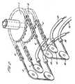
Fig. 1 is a plan view of the angulation system; andFig. 2 is a schematic perspective view showing the arrangement of pulleys, cables and angulation control.- The particular medical instrument being described here is an endoscope. However, it may be any medical instrument where cables which are normally manipulated to move a part of the instrument have to be rerouted so that force feedback can be applied to the cable.
- The described arrangement is adapted from a conventional endoscope control body. Both of the real and dummy endoscopes have an insertion portion leading from the control body ending at the endoscope tip. In the real instrument, this tip is manipulated to steer it through the colon. An umbilical is provided in both the real and dummy endoscopes leading from the control body to feed various cables to the control body.
- The control body is provided with a pair of co-axial rotatable knobs 1,2 as shown in
Fig. 2 . The outer knob 1, in this case, would, in a normal endoscope, be rotated to move the tip in an up/down direction, while the inner knob 2 would move the tip in a left/right direction orthogonal to the up/down direction. These described directions are only notional directions as, in use, the endoscope may be used in any orientation. Wrapped around each pulley is a wire chain drive 3,4 to each of which a cable is attached. In the illustrated example there are four cables which, for convenience, are denoted up cable 5, downcable 6, left cable 7 andright cable 8. - In a normal instrument, these
cables - In the dummy instrument, these cables must be rerouted along the umbilical of the instrument which directs them to an angulation feedback controller. In the angulation feedback controller, the up/down
cables 5,6 are connected to opposite sides of a force feedback motor and the left/right cable 7,8 are connected to a similar motor. - Rotation of the knobs 1,2 is detected and a system controller interprets this information together with information on the longitudinal and rotational positions of the tip of the endoscope. Using data representing a simulated model of a colon, software detects when the simulated tip of the endoscope comes into contact with the simulated colon wall. At this time, the controller sends a force feedback signal to the two feedback motors which hence provides a resistance to the movement of the cables 5-8 which is felt at the knobs 1,2 as a resistance to turning.
- In order to route each cable into the umbilical 9, the arrangement shown in
Fig. 1 and2 is employed.Fig. 1 shows the rerouting of two of the cables, namely thedown cable 6 and theright cable 8. A similar arrangement is provided on the opposite side of the control body as shown inFig. 2 . However, as this has the same construction and operation as the down/right configuration shown inFig. 1 , only this configuration is described in detail. Theright cable 8 is connected to the chain 4 that surrounds the inner knob 2. This cable then extends around afirst pulley 10 rotatably mounted on a housing 11 within the control body. Thepulley 10 turns the right cable through 180°. A sheath 12 is connected to the housing 11. Thecable 8 enters the sheath 12 at this point and is guided within this sheath into the umbilical which leads it to the feedback motor. - The
down cable 6 passes in a loop outside theright cable 8 around a pair of spacedpulleys 13,14 rotatably mounted on the housing 11. Thedown cable 6 enters asheath 15 attached to the housing 11 at connector 16 and is also guided into the umbilical to the other force feedback motor as described with reference to the right cable.
Claims (8)
- A dummy medical instrument for use in a simulator, the instrument comprising a control body with user manipulatable angulation control, an insertion tube and an umbilical extending from the control body, wherein in a real instrument corresponding to the one being simulated, at least one angulation cable would extend from the user manipulatable controls to the tip of the insertion tube such that movement of the angulation control changes the angulation of the tip,
characterised in that
in the dummy medical instrument the angulation cable extends from the user manipulatable angulation control, and down the umbilical to a device for controlling the resistance to movement of the cable to provide force feedback simulating the force which would be felt at the angulation control of a real instrument. - An instrument according to claim 1, wherein the cable extends from the control body and around a pulley where it is turned through substantially 180° before being routed down the umbilical.
- An instrument according to claims 1 and 2, wherein the angulation cable is a co-axial cable in which a central wire is moveable within a sleeve.
- An instrument according to claim 3, wherein the sleeve is removed for the portion of the cable surrounding the pulley, such that the wire engages directly with the pulley.
- An instrument according to any one of the preceding claims, wherein more than one cable is provided.
- An instrument according to claim 2 and claim 5, wherein each cable has its own pulley system.
- An instrument according to claim 6, wherein a first cable is wrapped around a single pulley, while a second cable is wrapped around a pair of pulleys which are spaced apart so that the second cable forms a loop outside of the loop formed by the first cable.
- An instrument according to claim 2 or any one of claims 3, 6 or 7 when dependent on claim 2, wherein the or each pulley preferably has a convex periphery, and at least a part of the periphery of the pulley is provided adjacent to the facing wall of a pulley housing.
Applications Claiming Priority (5)
| Application Number | Priority Date | Filing Date | Title |
|---|---|---|---|
| GB0200325 | 2002-01-08 | ||
| GBGB0200325.9AGB0200325D0 (en) | 2002-01-08 | 2002-01-08 | A dummy medical instrument for use in a simulator |
| GB0213981 | 2002-06-18 | ||
| GB0213981AGB2383890B (en) | 2002-01-08 | 2002-06-18 | A dummy medical instrument for use in a simulator |
| PCT/GB2002/005844WO2003058583A2 (en) | 2002-01-08 | 2002-12-20 | A dummy medical instrument for use in a simulator |
Publications (2)
| Publication Number | Publication Date |
|---|---|
| EP1472661A2 EP1472661A2 (en) | 2004-11-03 |
| EP1472661B1true EP1472661B1 (en) | 2008-08-27 |
Family
ID=26246922
Family Applications (1)
| Application Number | Title | Priority Date | Filing Date |
|---|---|---|---|
| EP02788213AExpired - LifetimeEP1472661B1 (en) | 2002-01-08 | 2002-12-20 | A dummy medical instrument for use in a simulator |
Country Status (4)
| Country | Link |
|---|---|
| US (1) | US7156664B2 (en) |
| EP (1) | EP1472661B1 (en) |
| AU (1) | AU2002353195A1 (en) |
| WO (1) | WO2003058583A2 (en) |
Families Citing this family (22)
| Publication number | Priority date | Publication date | Assignee | Title |
|---|---|---|---|---|
| WO2003021553A1 (en)* | 2001-09-03 | 2003-03-13 | Xitact S.A. | Device for simulating a rod-shaped surgical instrument for generating a feedback signal |
| WO2004036167A2 (en)* | 2002-10-18 | 2004-04-29 | Dentsply International Inc. | Dual-string dynamometer for measuring dental handpiece power at high speed and low torque |
| SE525157C2 (en)* | 2002-12-03 | 2004-12-14 | Mentice Ab | Simulation system for invasive surgery |
| JP4551769B2 (en)* | 2002-12-03 | 2010-09-29 | メンティセ アクチボラゲット | Interventional simulation equipment |
| SE0203567D0 (en)* | 2002-12-03 | 2002-12-03 | Mentice Ab | In interventional simulator control system |
| JP4355291B2 (en)* | 2002-12-03 | 2009-10-28 | メンティセ アクチボラゲット | Interventional simulator system |
| GB2409326B (en)* | 2003-12-19 | 2005-12-07 | Keymed | A dummy medical instrument for use in a simulator |
| GB2418521B (en) | 2004-09-22 | 2007-05-30 | Keymed | Endoscopy training simulator |
| US9211393B2 (en)* | 2006-06-05 | 2015-12-15 | Medtronic Cryocath Lp | Distal cooling distribution system for a medical device |
| US7871395B2 (en)* | 2006-06-05 | 2011-01-18 | Medtronic Cryocath Lp | Conduit management system |
| US9892659B2 (en) | 2007-05-21 | 2018-02-13 | Johnson County Community College Foundation, Inc. | Medical device and procedure simulation and training |
| US9886874B2 (en) | 2007-05-21 | 2018-02-06 | Johnson County Community College Foundation, Inc. | Medical device and procedure simulation and training |
| US9280916B2 (en) | 2007-05-21 | 2016-03-08 | Johnson County Community College Foundation, Inc. | Healthcare training system and method |
| US10186172B2 (en) | 2007-05-21 | 2019-01-22 | Jc3 Innovations, Llc | Blood glucose testing and monitoring system and method |
| US8251703B2 (en)* | 2007-05-21 | 2012-08-28 | Johnson County Community College Foundation, Inc. | Healthcare training system and method |
| US9905135B2 (en) | 2007-05-21 | 2018-02-27 | Jc3 Innovations, Llc | Medical device and procedure simulation and training |
| US9916773B2 (en) | 2007-05-21 | 2018-03-13 | Jc3 Innovations, Llc | Medical device and procedure simulation and training |
| US9711066B2 (en) | 2009-08-18 | 2017-07-18 | Airway Limited | Endoscope simulator |
| GB2511336B (en)* | 2013-02-28 | 2017-10-25 | Keymed (Medical & Ind Equipment) Ltd | A dummy instrument for use in a simulator |
| GB2511338B (en)* | 2013-02-28 | 2017-11-15 | Keymed (Medical & Ind Equipment) Ltd | A Dummy Instrument for use in a Simulator |
| US9250160B2 (en) | 2013-03-15 | 2016-02-02 | American Dental Association | Method and apparatus for characterizing handpieces |
| WO2018118858A1 (en) | 2016-12-19 | 2018-06-28 | National Board Of Medical Examiners | Medical training and performance assessment instruments, methods, and systems |
Family Cites Families (13)
| Publication number | Priority date | Publication date | Assignee | Title |
|---|---|---|---|---|
| GB2252656B (en) | 1991-02-11 | 1994-12-14 | Keymed | Improvements in endoscopy training apparatus |
| US5623582A (en)* | 1994-07-14 | 1997-04-22 | Immersion Human Interface Corporation | Computer interface or control input device for laparoscopic surgical instrument and other elongated mechanical objects |
| US6929481B1 (en)* | 1996-09-04 | 2005-08-16 | Immersion Medical, Inc. | Interface device and method for interfacing instruments to medical procedure simulation systems |
| WO1998010387A2 (en)* | 1996-09-04 | 1998-03-12 | Ht Medical Systems, Inc. | Interventional radiology interface apparatus and method |
| JP2997801B2 (en)* | 1997-09-18 | 2000-01-11 | オリンパス光学工業株式会社 | Endoscope device |
| IL123073A0 (en)* | 1998-01-26 | 1998-09-24 | Simbionix Ltd | Endoscopic tutorial system |
| US6470302B1 (en)* | 1998-01-28 | 2002-10-22 | Immersion Medical, Inc. | Interface device and method for interfacing instruments to vascular access simulation systems |
| US6113395A (en)* | 1998-08-18 | 2000-09-05 | Hon; David C. | Selectable instruments with homing devices for haptic virtual reality medical simulation |
| DE19935965A1 (en) | 1999-07-30 | 2001-02-01 | Wolff Walsrode Ag | Biodegradable composite films |
| AU4872701A (en)* | 2000-05-19 | 2001-11-26 | Simbionics Ltd. | Tools for endoscopic tutorial system |
| DE10055292B4 (en)* | 2000-11-03 | 2004-02-12 | Karl Storz Gmbh & Co. Kg | Simulator device with at least two degrees of freedom of movement for use with a real instrument |
| US7056123B2 (en)* | 2001-07-16 | 2006-06-06 | Immersion Corporation | Interface apparatus with cable-driven force feedback and grounded actuators |
| US7060025B2 (en)* | 2002-03-15 | 2006-06-13 | Ethicon Endo-Surgery, Inc. | Method for controlling position of medical instruments |
- 2002
- 2002-12-20EPEP02788213Apatent/EP1472661B1/ennot_activeExpired - Lifetime
- 2002-12-20WOPCT/GB2002/005844patent/WO2003058583A2/enactiveIP Right Grant
- 2002-12-20AUAU2002353195Apatent/AU2002353195A1/ennot_activeAbandoned
- 2002-12-20USUS10/500,410patent/US7156664B2/ennot_activeExpired - Fee Related
Also Published As
| Publication number | Publication date |
|---|---|
| AU2002353195A1 (en) | 2003-07-24 |
| EP1472661A2 (en) | 2004-11-03 |
| WO2003058583A3 (en) | 2003-09-18 |
| AU2002353195A8 (en) | 2003-07-24 |
| US7156664B2 (en) | 2007-01-02 |
| WO2003058583A2 (en) | 2003-07-17 |
| US20050042588A1 (en) | 2005-02-24 |
Similar Documents
| Publication | Publication Date | Title |
|---|---|---|
| EP1472661B1 (en) | A dummy medical instrument for use in a simulator | |
| KR102453163B1 (en) | Surgical apparatus | |
| US9649174B2 (en) | User interface with state machine for alternate tool mode for robotic surgical tools | |
| US7404716B2 (en) | Interface apparatus with cable-driven force feedback and four grounded actuators | |
| US7573461B2 (en) | Physically realistic computer simulation of medical procedures | |
| EP1695326A1 (en) | A dummy medical instrument for use in a simulator | |
| US9827050B2 (en) | User interface device for surgical simulation system | |
| JP2016519793A (en) | Modular exoskeleton force feedback controller | |
| JP4117949B2 (en) | Force interface device with 6-axis force feedback | |
| JP4117954B2 (en) | Haptic interface device with 4-axis force feedback | |
| EP1722346A1 (en) | An endoscopy simulation system | |
| GB2383890A (en) | Angulation control for dummy medical instrument, e.g. endoscope. | |
| WO2004015654A1 (en) | A dummy medical instrument for use in a simulator, such as an endoscope | |
| US11657730B2 (en) | Simulator for manual tasks | |
| EP1638065B1 (en) | An instrument for use in a medical simulator | |
| JP2006116296A (en) | Endoscopy training simulator | |
| CN118265963A (en) | Information processing device for controlling the position of a movable part | |
| US20060257835A1 (en) | Endoscopy simulation system | |
| JP2002102537A (en) | Computer game controller | |
| JPH0654794A (en) | Automatically curved type endoscope | |
| JP6857034B2 (en) | Training simulator device and training simulator | |
| WO2017145431A1 (en) | Endoscope |
Legal Events
| Date | Code | Title | Description |
|---|---|---|---|
| PUAI | Public reference made under article 153(3) epc to a published international application that has entered the european phase | Free format text:ORIGINAL CODE: 0009012 | |
| 17P | Request for examination filed | Effective date:20040621 | |
| AK | Designated contracting states | Kind code of ref document:A2 Designated state(s):AT BE BG CH CY CZ DE DK EE ES FI FR GB GR IE IT LI LU MC NL PT SE SI SK TR | |
| AX | Request for extension of the european patent | Extension state:AL LT LV MK RO | |
| GRAP | Despatch of communication of intention to grant a patent | Free format text:ORIGINAL CODE: EPIDOSNIGR1 | |
| GRAS | Grant fee paid | Free format text:ORIGINAL CODE: EPIDOSNIGR3 | |
| GRAA | (expected) grant | Free format text:ORIGINAL CODE: 0009210 | |
| RBV | Designated contracting states (corrected) | Designated state(s):AT BE BG CH CY CZ DE DK EE ES FI FR GR IE IT LI LU MC NL PT SE SI SK TR | |
| AK | Designated contracting states | Kind code of ref document:B1 Designated state(s):AT BE BG CH CY CZ DE DK EE ES FI FR GR IE IT LI LU MC NL PT SE SI SK TR | |
| REG | Reference to a national code | Ref country code:CH Ref legal event code:EP | |
| REG | Reference to a national code | Ref country code:IE Ref legal event code:FG4D | |
| REF | Corresponds to: | Ref document number:60228625 Country of ref document:DE Date of ref document:20081009 Kind code of ref document:P | |
| PG25 | Lapsed in a contracting state [announced via postgrant information from national office to epo] | Ref country code:ES Free format text:LAPSE BECAUSE OF FAILURE TO SUBMIT A TRANSLATION OF THE DESCRIPTION OR TO PAY THE FEE WITHIN THE PRESCRIBED TIME-LIMIT Effective date:20081208 Ref country code:NL Free format text:LAPSE BECAUSE OF FAILURE TO SUBMIT A TRANSLATION OF THE DESCRIPTION OR TO PAY THE FEE WITHIN THE PRESCRIBED TIME-LIMIT Effective date:20080827 | |
| PG25 | Lapsed in a contracting state [announced via postgrant information from national office to epo] | Ref country code:SI Free format text:LAPSE BECAUSE OF FAILURE TO SUBMIT A TRANSLATION OF THE DESCRIPTION OR TO PAY THE FEE WITHIN THE PRESCRIBED TIME-LIMIT Effective date:20080827 Ref country code:AT Free format text:LAPSE BECAUSE OF FAILURE TO SUBMIT A TRANSLATION OF THE DESCRIPTION OR TO PAY THE FEE WITHIN THE PRESCRIBED TIME-LIMIT Effective date:20080827 Ref country code:FI Free format text:LAPSE BECAUSE OF FAILURE TO SUBMIT A TRANSLATION OF THE DESCRIPTION OR TO PAY THE FEE WITHIN THE PRESCRIBED TIME-LIMIT Effective date:20080827 | |
| PG25 | Lapsed in a contracting state [announced via postgrant information from national office to epo] | Ref country code:BE Free format text:LAPSE BECAUSE OF FAILURE TO SUBMIT A TRANSLATION OF THE DESCRIPTION OR TO PAY THE FEE WITHIN THE PRESCRIBED TIME-LIMIT Effective date:20080827 | |
| PG25 | Lapsed in a contracting state [announced via postgrant information from national office to epo] | Ref country code:DK Free format text:LAPSE BECAUSE OF FAILURE TO SUBMIT A TRANSLATION OF THE DESCRIPTION OR TO PAY THE FEE WITHIN THE PRESCRIBED TIME-LIMIT Effective date:20080827 Ref country code:BG Free format text:LAPSE BECAUSE OF FAILURE TO SUBMIT A TRANSLATION OF THE DESCRIPTION OR TO PAY THE FEE WITHIN THE PRESCRIBED TIME-LIMIT Effective date:20081127 | |
| PG25 | Lapsed in a contracting state [announced via postgrant information from national office to epo] | Ref country code:CZ Free format text:LAPSE BECAUSE OF FAILURE TO SUBMIT A TRANSLATION OF THE DESCRIPTION OR TO PAY THE FEE WITHIN THE PRESCRIBED TIME-LIMIT Effective date:20080827 Ref country code:SK Free format text:LAPSE BECAUSE OF FAILURE TO SUBMIT A TRANSLATION OF THE DESCRIPTION OR TO PAY THE FEE WITHIN THE PRESCRIBED TIME-LIMIT Effective date:20080827 Ref country code:PT Free format text:LAPSE BECAUSE OF FAILURE TO SUBMIT A TRANSLATION OF THE DESCRIPTION OR TO PAY THE FEE WITHIN THE PRESCRIBED TIME-LIMIT Effective date:20090127 | |
| PLBE | No opposition filed within time limit | Free format text:ORIGINAL CODE: 0009261 | |
| STAA | Information on the status of an ep patent application or granted ep patent | Free format text:STATUS: NO OPPOSITION FILED WITHIN TIME LIMIT | |
| PG25 | Lapsed in a contracting state [announced via postgrant information from national office to epo] | Ref country code:MC Free format text:LAPSE BECAUSE OF NON-PAYMENT OF DUE FEES Effective date:20081231 Ref country code:EE Free format text:LAPSE BECAUSE OF FAILURE TO SUBMIT A TRANSLATION OF THE DESCRIPTION OR TO PAY THE FEE WITHIN THE PRESCRIBED TIME-LIMIT Effective date:20080827 | |
| REG | Reference to a national code | Ref country code:CH Ref legal event code:PL | |
| 26N | No opposition filed | Effective date:20090528 | |
| PG25 | Lapsed in a contracting state [announced via postgrant information from national office to epo] | Ref country code:IT Free format text:LAPSE BECAUSE OF FAILURE TO SUBMIT A TRANSLATION OF THE DESCRIPTION OR TO PAY THE FEE WITHIN THE PRESCRIBED TIME-LIMIT Effective date:20080827 | |
| REG | Reference to a national code | Ref country code:IE Ref legal event code:MM4A | |
| PG25 | Lapsed in a contracting state [announced via postgrant information from national office to epo] | Ref country code:IE Free format text:LAPSE BECAUSE OF NON-PAYMENT OF DUE FEES Effective date:20081220 Ref country code:CH Free format text:LAPSE BECAUSE OF NON-PAYMENT OF DUE FEES Effective date:20081231 Ref country code:LI Free format text:LAPSE BECAUSE OF NON-PAYMENT OF DUE FEES Effective date:20081231 | |
| PG25 | Lapsed in a contracting state [announced via postgrant information from national office to epo] | Ref country code:SE Free format text:LAPSE BECAUSE OF FAILURE TO SUBMIT A TRANSLATION OF THE DESCRIPTION OR TO PAY THE FEE WITHIN THE PRESCRIBED TIME-LIMIT Effective date:20081127 | |
| PG25 | Lapsed in a contracting state [announced via postgrant information from national office to epo] | Ref country code:CY Free format text:LAPSE BECAUSE OF FAILURE TO SUBMIT A TRANSLATION OF THE DESCRIPTION OR TO PAY THE FEE WITHIN THE PRESCRIBED TIME-LIMIT Effective date:20080827 Ref country code:LU Free format text:LAPSE BECAUSE OF NON-PAYMENT OF DUE FEES Effective date:20081220 | |
| PG25 | Lapsed in a contracting state [announced via postgrant information from national office to epo] | Ref country code:TR Free format text:LAPSE BECAUSE OF FAILURE TO SUBMIT A TRANSLATION OF THE DESCRIPTION OR TO PAY THE FEE WITHIN THE PRESCRIBED TIME-LIMIT Effective date:20080827 | |
| PG25 | Lapsed in a contracting state [announced via postgrant information from national office to epo] | Ref country code:GR Free format text:LAPSE BECAUSE OF FAILURE TO SUBMIT A TRANSLATION OF THE DESCRIPTION OR TO PAY THE FEE WITHIN THE PRESCRIBED TIME-LIMIT Effective date:20081128 | |
| REG | Reference to a national code | Ref country code:FR Ref legal event code:PLFP Year of fee payment:14 | |
| REG | Reference to a national code | Ref country code:FR Ref legal event code:PLFP Year of fee payment:15 | |
| REG | Reference to a national code | Ref country code:FR Ref legal event code:PLFP Year of fee payment:16 | |
| PGFP | Annual fee paid to national office [announced via postgrant information from national office to epo] | Ref country code:FR Payment date:20171221 Year of fee payment:16 Ref country code:DE Payment date:20171211 Year of fee payment:16 | |
| REG | Reference to a national code | Ref country code:DE Ref legal event code:R119 Ref document number:60228625 Country of ref document:DE | |
| PG25 | Lapsed in a contracting state [announced via postgrant information from national office to epo] | Ref country code:FR Free format text:LAPSE BECAUSE OF NON-PAYMENT OF DUE FEES Effective date:20181231 Ref country code:DE Free format text:LAPSE BECAUSE OF NON-PAYMENT OF DUE FEES Effective date:20190702 |