EP1471836B1 - Apparatus for performing spinal surgery - Google Patents
Apparatus for performing spinal surgeryDownload PDFInfo
- Publication number
- EP1471836B1 EP1471836B1EP02799213AEP02799213AEP1471836B1EP 1471836 B1EP1471836 B1EP 1471836B1EP 02799213 AEP02799213 AEP 02799213AEP 02799213 AEP02799213 AEP 02799213AEP 1471836 B1EP1471836 B1EP 1471836B1
- Authority
- EP
- European Patent Office
- Prior art keywords
- vertebral body
- cutting
- arm
- endplate
- cutting guide
- Prior art date
- Legal status (The legal status is an assumption and is not a legal conclusion. Google has not performed a legal analysis and makes no representation as to the accuracy of the status listed.)
- Expired - Lifetime
Links
- 238000001356surgical procedureMethods0.000titleabstractdescription7
- 238000005520cutting processMethods0.000claimsabstractdescription186
- 210000000988bone and boneAnatomy0.000description91
- 238000000034methodMethods0.000description34
- 230000001054cortical effectEffects0.000description31
- 230000006835compressionEffects0.000description13
- 238000007906compressionMethods0.000description13
- 125000006850spacer groupChemical group0.000description10
- 206010016654FibrosisDiseases0.000description6
- 230000004761fibrosisEffects0.000description6
- 230000004927fusionEffects0.000description6
- 238000005452bendingMethods0.000description5
- 239000002639bone cementSubstances0.000description5
- 238000002594fluoroscopyMethods0.000description5
- 239000007943implantSubstances0.000description5
- 238000002513implantationMethods0.000description5
- 238000013459approachMethods0.000description3
- 238000012544monitoring processMethods0.000description3
- 208000007623LordosisDiseases0.000description2
- 230000008901benefitEffects0.000description2
- 230000000694effectsEffects0.000description2
- 239000012634fragmentSubstances0.000description2
- 230000002706hydrostatic effectEffects0.000description2
- 239000000463materialSubstances0.000description2
- 230000008569processEffects0.000description2
- 239000007787solidSubstances0.000description2
- 0*C1*CCCC1Chemical compound*C1*CCCC10.000description1
- 229910000684Cobalt-chromeInorganic materials0.000description1
- 206010061246Intervertebral disc degenerationDiseases0.000description1
- 241000283984RodentiaSpecies0.000description1
- 230000002159abnormal effectEffects0.000description1
- 239000006096absorbing agentSubstances0.000description1
- 230000009471actionEffects0.000description1
- 229910045601alloyInorganic materials0.000description1
- 239000000956alloySubstances0.000description1
- 238000011882arthroplastyMethods0.000description1
- 239000000560biocompatible materialSubstances0.000description1
- 239000000316bone substituteSubstances0.000description1
- 230000008859changeEffects0.000description1
- 239000010952cobalt-chromeSubstances0.000description1
- 230000001186cumulative effectEffects0.000description1
- 125000004122cyclic groupChemical group0.000description1
- 208000018180degenerative disc diseaseDiseases0.000description1
- 230000003412degenerative effectEffects0.000description1
- 201000010099diseaseDiseases0.000description1
- 208000037265diseases, disorders, signs and symptomsDiseases0.000description1
- 238000005553drillingMethods0.000description1
- 230000009977dual effectEffects0.000description1
- 230000035876healingEffects0.000description1
- 238000007373indentationMethods0.000description1
- 238000003780insertionMethods0.000description1
- 230000037431insertionEffects0.000description1
- 208000021600intervertebral disc degenerative diseaseDiseases0.000description1
- 230000001045lordotic effectEffects0.000description1
- 239000002184metalSubstances0.000description1
- 238000012986modificationMethods0.000description1
- 230000004048modificationEffects0.000description1
- 238000012806monitoring deviceMethods0.000description1
- 230000000921morphogenic effectEffects0.000description1
- 230000000149penetrating effectEffects0.000description1
- 102000004169proteins and genesHuman genes0.000description1
- 108090000623proteins and genesProteins0.000description1
- 230000004044responseEffects0.000description1
- 238000010079rubber tappingMethods0.000description1
- 230000035939shockEffects0.000description1
- 210000004872soft tissueAnatomy0.000description1
- 230000000087stabilizing effectEffects0.000description1
- 239000010935stainless steelSubstances0.000description1
- 229910001220stainless steelInorganic materials0.000description1
- 210000001519tissueAnatomy0.000description1
- XLYOFNOQVPJJNP-UHFFFAOYSA-NwaterSubstancesOXLYOFNOQVPJJNP-UHFFFAOYSA-N0.000description1
Images


Classifications
- A—HUMAN NECESSITIES
- A61—MEDICAL OR VETERINARY SCIENCE; HYGIENE
- A61B—DIAGNOSIS; SURGERY; IDENTIFICATION
- A61B17/00—Surgical instruments, devices or methods
- A61B17/16—Instruments for performing osteoclasis; Drills or chisels for bones; Trepans
- A61B17/17—Guides or aligning means for drills, mills, pins or wires
- A61B17/1735—Guides or aligning means for drills, mills, pins or wires for rasps or chisels
- A—HUMAN NECESSITIES
- A61—MEDICAL OR VETERINARY SCIENCE; HYGIENE
- A61B—DIAGNOSIS; SURGERY; IDENTIFICATION
- A61B17/00—Surgical instruments, devices or methods
- A61B17/02—Surgical instruments, devices or methods for holding wounds open, e.g. retractors; Tractors
- A61B17/025—Joint distractors
- A—HUMAN NECESSITIES
- A61—MEDICAL OR VETERINARY SCIENCE; HYGIENE
- A61B—DIAGNOSIS; SURGERY; IDENTIFICATION
- A61B17/00—Surgical instruments, devices or methods
- A61B17/14—Surgical saws
- A61B17/15—Guides therefor
- A—HUMAN NECESSITIES
- A61—MEDICAL OR VETERINARY SCIENCE; HYGIENE
- A61B—DIAGNOSIS; SURGERY; IDENTIFICATION
- A61B17/00—Surgical instruments, devices or methods
- A61B17/16—Instruments for performing osteoclasis; Drills or chisels for bones; Trepans
- A61B17/1604—Chisels; Rongeurs; Punches; Stamps
- A—HUMAN NECESSITIES
- A61—MEDICAL OR VETERINARY SCIENCE; HYGIENE
- A61B—DIAGNOSIS; SURGERY; IDENTIFICATION
- A61B17/00—Surgical instruments, devices or methods
- A61B17/16—Instruments for performing osteoclasis; Drills or chisels for bones; Trepans
- A61B17/1604—Chisels; Rongeurs; Punches; Stamps
- A61B17/1606—Chisels; Rongeurs; Punches; Stamps of forceps type, i.e. having two jaw elements moving relative to each other
- A61B17/1608—Chisels; Rongeurs; Punches; Stamps of forceps type, i.e. having two jaw elements moving relative to each other the two jaw elements being linked to two elongated shaft elements moving longitudinally relative to each other
- A61B17/1611—Chisels; Rongeurs; Punches; Stamps of forceps type, i.e. having two jaw elements moving relative to each other the two jaw elements being linked to two elongated shaft elements moving longitudinally relative to each other the two jaw elements being integral with respective elongate shaft elements
- A—HUMAN NECESSITIES
- A61—MEDICAL OR VETERINARY SCIENCE; HYGIENE
- A61B—DIAGNOSIS; SURGERY; IDENTIFICATION
- A61B17/00—Surgical instruments, devices or methods
- A61B17/16—Instruments for performing osteoclasis; Drills or chisels for bones; Trepans
- A61B17/1662—Instruments for performing osteoclasis; Drills or chisels for bones; Trepans for particular parts of the body
- A61B17/1671—Instruments for performing osteoclasis; Drills or chisels for bones; Trepans for particular parts of the body for the spine
- A—HUMAN NECESSITIES
- A61—MEDICAL OR VETERINARY SCIENCE; HYGIENE
- A61B—DIAGNOSIS; SURGERY; IDENTIFICATION
- A61B17/00—Surgical instruments, devices or methods
- A61B17/16—Instruments for performing osteoclasis; Drills or chisels for bones; Trepans
- A61B17/17—Guides or aligning means for drills, mills, pins or wires
- A61B17/1739—Guides or aligning means for drills, mills, pins or wires specially adapted for particular parts of the body
- A61B17/1757—Guides or aligning means for drills, mills, pins or wires specially adapted for particular parts of the body for the spine
- A—HUMAN NECESSITIES
- A61—MEDICAL OR VETERINARY SCIENCE; HYGIENE
- A61B—DIAGNOSIS; SURGERY; IDENTIFICATION
- A61B17/00—Surgical instruments, devices or methods
- A61B17/16—Instruments for performing osteoclasis; Drills or chisels for bones; Trepans
- A61B17/1613—Component parts
- A61B17/1615—Drill bits, i.e. rotating tools extending from a handpiece to contact the worked material
- A61B17/1617—Drill bits, i.e. rotating tools extending from a handpiece to contact the worked material with mobile or detachable parts
- A—HUMAN NECESSITIES
- A61—MEDICAL OR VETERINARY SCIENCE; HYGIENE
- A61B—DIAGNOSIS; SURGERY; IDENTIFICATION
- A61B17/00—Surgical instruments, devices or methods
- A61B2017/00004—(bio)absorbable, (bio)resorbable or resorptive
- A—HUMAN NECESSITIES
- A61—MEDICAL OR VETERINARY SCIENCE; HYGIENE
- A61B—DIAGNOSIS; SURGERY; IDENTIFICATION
- A61B17/00—Surgical instruments, devices or methods
- A61B17/02—Surgical instruments, devices or methods for holding wounds open, e.g. retractors; Tractors
- A61B17/025—Joint distractors
- A61B2017/0256—Joint distractors for the spine
- A—HUMAN NECESSITIES
- A61—MEDICAL OR VETERINARY SCIENCE; HYGIENE
- A61B—DIAGNOSIS; SURGERY; IDENTIFICATION
- A61B17/00—Surgical instruments, devices or methods
- A61B17/32—Surgical cutting instruments
- A61B2017/320052—Guides for cutting instruments
- A—HUMAN NECESSITIES
- A61—MEDICAL OR VETERINARY SCIENCE; HYGIENE
- A61B—DIAGNOSIS; SURGERY; IDENTIFICATION
- A61B90/00—Instruments, implements or accessories specially adapted for surgery or diagnosis and not covered by any of the groups A61B1/00 - A61B50/00, e.g. for luxation treatment or for protecting wound edges
- A61B90/03—Automatic limiting or abutting means, e.g. for safety
- A61B2090/033—Abutting means, stops, e.g. abutting on tissue or skin
- A61B2090/034—Abutting means, stops, e.g. abutting on tissue or skin abutting on parts of the device itself
Definitions
- This inventionrelates to the field of spinal surgery. More specifically, this invention relates to apparatuses for creating cavities in vertebral bodies and in intervertebral discs located between the vertebral bodies. This invention also relates to methods for creating such cavities. Once the cavities are created with the apparatuses and according to the methods of the present invention, an intervertebral prosthetic device, designed to replace a damaged intervertebral disc, can be implanted in the cavities. Moreover, the implanted device may be used in vertebral body fusion or in reconstruction of mobile discs through spinal arthroplasty (i.e., disc replacement).
- the human spineis a flexible structure comprised of twenty-five vertebrae. Intervertebral discs separate and cushion adjacent vertebrae. The intervertebral discs act as shock absorbers and allow bending between the vertebrae.
- An intervertebral disccomprises two major components: the nucleus pulposus and the annulus fibrosis.
- the nucleus pulposusis centrally located in the disc and occupies 25-40% of the disc's total cross-sectional area.
- the nucleus pulposususually contains 70-90% water by weight and mechanically may function like an incompressible hydrostatic material.
- the annulus fibrosissurrounds the nucleus pulposus and resists torsional and bending forces applied to the disc. Thus, the annulus fibrosis serves as the disc's main stabilizing structure.
- a healthy discrelies on the unique relationship of the nucleus and annulus to one another.
- the top and bottom surfaces of intervertebral discsabut vertebral body endplates.
- a conventional treatment for degenerative disc diseaseis spinal fusion.
- a surgeonremoves the damaged natural disc and then fuses the two adjacent vertebral bodies into one piece.
- the surgeonfuses the vertebral bodies by grafting bone between the adjacent vertebrae and sometimes uses metal rods, cages, or screws to hold the graft in place until the graft heals.
- Other fusion proceduresdo not require surgical removal of the disc.
- spinal fusionmay alleviate pain associated with degenerative disk disease, it also results in loss of motion at the fused vertebral joint. Lack of motion at the fused site puts abnormal loads on the adjacent discs above and below the fusion. This additional pressure may cause the adjacent discs to degenerate and produce pain, thereby recreating the problem which originally existed.
- various prosthetic deviceswere developed to replace the damaged disc with a suitable biomechanical equivalent.
- U.S. Patent No. 4,759,769 to Hedman et aldiscloses a synthetic disc having upper and lower plates hinged together. Although the hinged disc allows forward bending between adjacent vertebrae, the hinged disc does not allow axial compression or lateral flexion. Nor does it allow axial rotation of the vertebral column at the site of the implant. Therefore, the Hedman et al. device lacks many of the biomechanics of a natural disc.
- the prosthetic disc device disclosed in U.S. Patent No. 4,309,777 to Patildoes not replicate natural motion between adjacent discs.
- the Patil deviceincludes two cups, one overlapping the other and spaced from the other by springs. The cups move only in a single axial dimension.
- the Patil devicedoes not enable natural flexion of the spine in any direction.
- the highly constrained motion of the Patil devicecan lead to high device/tissue interface stresses and implant loosening.
- U.S. Patent No. 5,827,328 to Buttermanndiscloses an intervertebral synthetic prosthetic device designed to replace the biomechanical functionality of a failing intervertebral disc.
- One embodiment of the Buttermann deviceincludes a first fixation member for implantation in a first vertebral body, a second fixation member for implantation in a second vertebral body adjacent the first vertebral body, and a compressible member that is positioned between the first and second fixation members.
- the Buttermann deviceovercomes the aforementioned problems with synthetic devices. Disk excision instruments are known.
- EP-A-0 614 647(Smith & Nephew Richards Inc (US)) describes a suction punch having handles that bring together a pair of cutting edges in a typical Kerison rongeur type of cutting action.
- JP 2000 325353 A(Suga Hisayoshi) describes an instrument having a cylindrical instrument body with a cutting edge and a frame that fixes to an external aspect of the vertebral body.
- the cutting guidefor use in removing bone from a vertebral body.
- the cutting guideincludes a sidewall that defines an internal cavity.
- the sidewallhas (i) a first edge to face toward and to contact a vertebral body in at least three points and (ii) a second, opposite edge to face away from the vertebral body.
- the first edgeincludes at least two concave portions and at least one convex portion oriented generally perpendicular to the at least two concave portions.
- the sidewall of the cutting guidemay be comprised of four walls arranged to form a rectangular cross-section. At least one of the four walls may include a hole extending from the first edge to the second edge to receive a fastener therethrough.
- the first edge of the sidewallmay be concave along a first of the four walls and along an opposite second of the four walls, and it may be convex along a third of the four walls and along an opposite fourth of the four walls.
- the concave first edge along the first wallmay be a mirror image of the concave first edge along the second wall.
- the convex first edge along the third wallmay be a mirror image of the convex first edge along the fourth wall.
- the concave and convex edgesmay each comprise one smooth surface, they also may be formed by a plurality of adjacent surfaces.
- the chisel guidefor use in cutting bone of a vertebral body.
- the chisel guideincludes a first block member to be positioned adjacent the vertebral body and a second block member connected to the first block member.
- the second block memberhas a channel, formed on one side thereof, which terminates at the first block member.
- the first block member and the second block member of the chisel guidemay be formed as one integral piece. Further, the second block member may extend beyond the perimeter of the first block member in at least one dimension to form a shoulder with the first block member. For example, the second block member may have a width greater than the width of the first block member such that the second block member forms a pair of opposed shoulders with respect to the first member.
- the combinationincludes a cutting guide having a sidewall defining an internal cavity.
- the sidewallin turn, has a first edge to face toward and to contact a vertebral body in at least three points and a second, opposite edge to face away from the vertebral body.
- the combinationalso includes a chisel guide.
- the chisel guidehas a first block member and a second block member connected to the first block member. The first block member is adapted to be inserted into the internal cavity of the cutting guide to position the first block member adjacent the vertebral body such that a passage remains between a first side of the first block member and an inner surface of the sidewall of the cutting guide.
- the first and second block membersmay be formed as an integral piece.
- the second block membermay be solid.
- the second block membermay extend beyond the perimeter of the first block member, in at least one dimension, to form a shoulder with the first block member.
- the second block membermay have a width which is greater than the width of the first block member so that the second block member forms a pair of opposed shoulders with respect to the first block member.
- the second block membermay include a channel which is formed on one side thereof and which terminates at the first block member.
- This apparatusincludes a shaft and a reamer.
- the shafthas a.first end and a second end, and the second end of the shaft is connectable to a power source.
- the reameris connected to the first end of the shaft.
- the reamerincludes at least one cutting member and a collection space to collect bone fragments cut by the cutting member. A slot, through which the bone fragments pass into the collection space, is adjacent the at least one cutting member.
- the reamermay be detachably connected to the first end of the shaft.
- the reamermay have a circular cross-section.
- Various power sourcessuch as a drill, may be used to rotate the second end of the shaft.
- the cutting memberis positioned on a bone engaging surface of the reamer.
- the bone engaging surface of the reamermay be flat except for the cutting implement and slots associated therewith.
- an apparatus for creating a cavity in a vertebral body endplate and in an intervertebral discincludes a handle, a first arm, and a second arm movable toward the first arm upon actuation of the handle.
- the apparatusalso includes a first cutting implement that is mounted to the first arm and that has a generally circular sidewall that terminates in a first cutting edge.
- the first cutting edgefaces away from the first arm.
- the first cutting edgealso may face away from the second arm.
- the first cutting edgemay face toward the second arm.
- the apparatusmay also include a second cutting implement mounted to the second arm and having a generally circular sidewall that terminates in a second cutting edge, the second cutting edge facing away from the second arm and facing toward the first cutting edge so that, upon actuation of the handle, the first and second cutting edges move toward each other.
- the cutting edges of the cutting implementsmay be serrated.
- the cutting implementsalso may be rotatably mounted to their respective arms. Moreover, in an embodiment having two cutting implements, the cutting implements may be mounted to rotate about the same axis of rotation.
- the tensioner apparatusfor use in determining a proper elongation distance in a prosthesis implanted in a vertebral body.
- the tensioner apparatusincludes a first arm and a second arm, each having a handle portion and a separator portion. A pivot joins the first arm to the second arm and separates the separator portions from the handle portions.
- at least one tension measuring elementis positioned on the first arm; the tension measuring element may be a strain gage.
- the tensioner apparatusalso may include at least one strain gage positioned on the second arm.
- the strain gages positioned on the first and second armsmay be part of a Wheatstone bridge and may be positioned on the separator portions of the first and second arms, respectively.
- a method of creating a cavity in a vertebral bodyincludes removably attaching a cutting guide to an outer surface of a vertebral body.
- the cutting guidehas a cavity therein.
- the methodalso includes puncturing through the outer surface and cortical bone of the vertebral body along a perimeter of the cavity in the cutting guide, removing the punctured cortical bone of the vertebral body to expose bone in the interior of the vertebral body, and removing the bone in the interior of the vertebral body.
- the method of creating a cavity in a vertebral bodymay also include inserting a chisel guide in the cavity in the cutting guide.
- the puncturing stepmay include using the chisel guide to guide a chisel, having a chisel blade, along a perimeter of the cavity in the cutting guide.
- the puncturing stepmay be accomplished by using a motorized sagittal saw. Regardless of whether a chisel and chisel guide or a sagittal saw is used to puncture through the outer surface and cortical bone, the step of removing the bone in the interior of the vertebral body may be accomplished using a reamer.
- a method of creating an intervertebral disc cavityincludes providing an apparatus including a first arm having a first cutting implement attached thereto, a second arm, and a handle.
- the methodalso includes positioning the first arm in a cavity in a first vertebral body, compressing the handle of compressor so that the first and second arms move in a direction towards each other, cutting through the nucleus pulposus of the intervertebral disc with the first cutting implement, and removing the nucleus pulposus of the intervertebral disc to create the intervertebral disk cavity.
- This methodalso may include positioning the second arm of the compressor in a cavity in a second vertebral body, wherein the second arm has a second cutting implement thereon; and cutting through the nucleus pulposus of the intervertebral disc with the second cutting implement.
- the method for creating an intervertebral disc cavitymay also include, prior to the step of positioning a first arm of a compressor in a cavity in a first vertebral body, attaching a cutting guide to a surface of the first vertebral body, the cutting guide defining a cavity; cutting through the surface and cortical bone of the first vertebral body along an inside perimeter of the cavity in the cutting guide; removing the cut cortical bone of the first vertebral body to expose bone in an interior of the first vertebral body; removing the bone in the interior of the first vertebral body to create the first vertebral body cavity; and removing the cutting guide from the first vertebral body.
- the methodalso may include attaching the cutting guide to a surface of the second vertebral body; cutting through the surface and cortical bone of the second vertebral body along the inside perimeter of the cavity in the cutting guide; removing the cut cortical bone of the second vertebral body to expose the bone in the interior of the second vertebral body; and removing the bone in the interior of the second vertebral body to create the second vertebral body cavity.
- the implanted devicehas a fixation member implanted within a vertebral body and a compressible member implanted within an intervertebral disc.
- the methodincludes providing a tensioner including a first arm and a second arm each having a handle portion and a separator portion.
- a pivot pinjoins the first arm to the second arm and separates the separator portions from the handle portions.
- At least one strain gageis positioned on the first arm.
- the methodalso includes inserting the first and the second arms into the fixation member, and moving the handle portions toward each other to thereby move the separator portions away from each other until one of the separator portions contacts an upper member of the fixation member and the other of the separator portions contacts a lower member of the fixation member.
- the methodfurther includes elongating the fixation member with the tensioner, and monitoring a voltage measured by the at least one strain gage, the voltage being representative of the load applied by the tensioner and thus the reactive load experienced by the compressible member of the implanted device.
- FIG. 1Ais a top perspective view of a cutting guide
- FIG. 1Bis a top view of the cutting guide of FIG. 1A ;
- FIG. 1Cis a side elevation view of the cutting guide of FIG. 1 A;
- FIG. 1Dis a side elevation view of a cutting guide having an alternative shape
- FIG. 2Ais a top perspective view of a chisel guide
- FIG. 2Bis a top view of the chisel guide of FIG. 2A ;
- FIG. 2Cis a side elevation view of the chisel guide of FIG. 2A ;
- FIG. 2Dis a front elevation view of the chisel guide of FIG. 2A ;
- FIG. 3Ais a top perspective view of the chisel guide inserted into the cutting guide
- FIG. 3Bis a top perspective view of a chisel for use with the cutting guide and chisel guide of FIG. 3A ;
- FIG. 3Cis a perspective view of the chisel of FIG. 3B inserted into the cutting guide and chisel guide combination of FIG. 3A ;
- FIG. 4Ais an exploded side view, in cross section, of a rotatable shaft and reamer
- FIG. 4Bis an exploded perspective view of the rotatable shaft and reamer of FIG. 4A ;
- FIG. 4Cis a perspective view of the rotatable shaft and reamer of FIGS. 4A and 4B ;
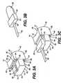
- FIG. 5Ais a perspective view of an endplate and nucleus cutter
- FIG. 5Bis a side elevation sectional view, in cross section, of the endplate and nucleus cutter of FIG 5A ;
- FIG. 5Cis a side elevation section view, in cross section, of an alternative embodiment of the endplate and nucleus cutter
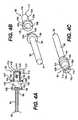
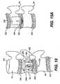
- FIG. 6Ais a side elevation view of a compressor having a pair of endplate and nucleus cutters mounted thereto;
- FIG. 6Bis a side elevation view of a distractor having one endplate and nucleus cutter mounted thereto;
- FIG. 6Cis an enlarged side elevation view, in cross section, of encircled area 6C-6C in FIG. 6A with the screw removed;
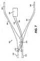
- FIG. 7is a side elevation view of a tensioner apparatus
- FIG. 8is a schematic view of a cutting guide affixed to a curved surface of a vertebral body
- FIG. 9Ais a schematic view of a cutting guide and chisel guide combination and a chisel engaged in the cutting guide and chisel combination to cut through the bone of the vertebral body;
- FIG. 9Bis a schematic view of a cutting guide affixed to a vertebral body and a sagittal saw positioned in the cutting guide to cut through the bone of the vertebral body;
- FIG. 10is a schematic view of a vertebral body with a section of the cortical bone removed from the vertebral body;
- FIG. 11is a schematic view of a reamer, positioned in the cutting guide, for drilling into the vertebral bone of the vertebral body to create a cavity;
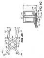
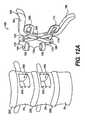
- FIG. 12Ais a schematic view of two adjacent vertebral bodies having cavities therein and a compressor having two endplate and nucleus cutters thereon;
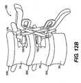
- FIG. 12Bis a schematic view of the compressor shown in FIG. 12A with the endplate and nucleus cutters inserted into the cavities of the adjacent vertebral bodies;
- FIG. 13is a schematic, cut-away left side view of an intervertebral prosthetic device implanted in adjacent vertebral bodies and in an intervertebral disc;
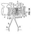
- FIG. 14is a schematic, cut-away left side view of a cavity in a vertebral body, showing the tensioner positioned therein;
- FIG. 15is a schematic, cut-away left side view of the adjacent vertebral bodies having an intervertebral prosthetic device implanted therein, wherein the vertebral bodies are provided with bone shavings to induce bone grafting;
- FIG. 16is a schematic left side view of the adjacent vertebral bodies with the cortical bone repositioned to cover the cavities in the vertebral bodies;
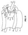
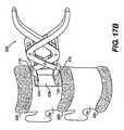
- FIG. 17Ais a schematic view of a vertebral body having a cavity therein and an alternative embodiment of the distractor having one endplate and nucleus cutter thereon;
- FIG. 17Bis a schematic view of the distractor shown in FIG. 17A with the endplate and nucleus cutter inserted into the cavity of the vertebral body and forced downward into the nucleus pulposus of the intervertebral disc;
- FIG. 18is a schematic, cut-away left side view of the vertebral body and intervertebral disc of FIG. 17B having a prosthetic device positioned therein;
- FIG. 19Ais a schematic view of a rotatable dome-shaped cutter.
- FIG. 19Bis a schematic, cut-away left side view of a vertebral body having a cavity formed therein by the rotatable dome-shaped cutter of FIG. 19A .
- a cutting guide 20for use in removing bone 22 from a vertebral body 24.
- the cutting guideis designed to be placed into contact with the outer surface of the vertebral body 24 to "guide" a surgical instrument as it cuts through the cortical bone of the vertebral body, as shown in FIGS. 8 and 9A-9B and as later described in more detail.
- the cutting guide 20has a sidewall that defines an internal cavity 34 extending through the cutting guide 20.
- the sidewallgenerally has four walls 26, 28, 30, 32 arranged to form a rectangular cross-section.
- the cavity 34is preferably rectangular in cross section, the walls 26, 28, 30, 32 can be configured to define a cavity that is square in cross-section or any other suitable geometric shape.
- the cutting guide 20has a first edge 38 to face toward and to contact the vertebral body 24.
- the cutting guidealso has a second, opposite edge 36 to face away from the vertebral body 24.
- the first edge 38 of the cutting guideis contoured to contact the vertebral body in at least three points, although it will be understood that the first edge 38 can have four or more points of contact with a vertebral body.
- the first edge 38includes both concave portions 40 and convex portions 42 configured to fit against the curved, outer surface of the vertebral body 24.
- the second edge 36 of the cutting guide 20is substantially planar.
- the concave portions 40 of the first edge 38are oriented generally perpendicular to the convex portions 42.
- the concave portions 40are formed along the first edge 38 of opposite walls 26, 30, and the convex portions 42 are formed along the first edge 38 of opposite walls 28, 32.
- the concave first edge along the wall 26preferably is a mirror image of the concave first edge along the wall 30.
- the convex first edge along wall 28preferably is a mirror image of the convex first edge along wall 32.
- the concave portion 40 of the first edge 38 of wall 26preferably terminates before it reaches either end of the wall 26 to create flattened portions 41; the same is true of the concave portion of wall 30.
- the concave portions 40 and convex portions 42may be smooth surfaces, they also may be formed by a plurality of adjacent straight surfaces.
- the convex portion 42preferably is a smooth, curved surface; however, it will be understood that the convex portion can be formed by a plurality of straight segments 41', as shown, for example, in FIG. 1D .
- a plurality of holes 44pass through the cutting guide 20 from edge 36 to edge 38. These holes 44 are adapted to receive fasteners 48, as shown in FIG. 8 , to secure the cutting guide 20 to the vertebral body 24. Although the holes 44 can be positioned anywhere along edges 36, 38, it is preferable that they be positioned to extend through walls 28, 32 having convex portions 42. In addition, although FIGS. 1A-1C show six holes 44, one of ordinary skill in the art will understand that fewer or more holes can be employed in the cutting guide 20 without departing from the broadest scope of the invention.
- a surgeonneed not position fasteners in all holes, but, in fact, may only need fasteners in two holes 44 to secure the cutting guide 20 to the vertebral body, depending on the surface contour of the vertebral body.
- three or four holes 44would receive a fastener 48.
- FIGS. 2A-2Dthere is shown a chisel guide 50 for use in cutting bone of a vertebral body 24.
- the chisel guide 50can be used in combination with the cutting guide 20 to guide a chisel 62, or osteotome, as seen in FIG. 3B , toward the cortical bone 22 of the vertebral body 24.
- the chisel 62then can cut through the bone 22 to expose the inside of the vertebral body 24, as will be later described in more detail.
- the chisel guide 50includes a first block member 54 to be positioned towards the vertebral body 24 and a second block member 52 connected to the first block member 54.
- the blocks 52, 54may be separate pieces joined together to form the chisel guide 50, they preferably are solid and integrally molded or machined as one piece.
- the second block 52preferably extends beyond the perimeter of the first block 54 in at least one dimension to form a shoulder 56 with respect to the first block 54.
- the first block 54has a first width W1
- the second block 52has a second width W2 greater than the first width W1, thereby forming opposed shoulders 56 with respect to the first block 54.
- the second block 52can have a channel 58 formed in a top side 60 thereof.
- the channel 58terminates at the first block 54.
- the channel 58may receive a projection 59 on a chisel 62, as shown in FIG. 3B , when the chisel guide 50 is positioned in the cutting guide 20.
- the blocks 52, 54can have approximately the same height, they are vertically offset from each other, thereby creating two ridges 76, 78.
- the first ridge 76formed by part of the second block 52, is designed to engage the flat edge 36 of the cutting guide 20.
- the second ridge 78, formed by part of the first block 54serves as a chisel guiding edge by abutting a surface 63 on the chisel 62 to prevent the chisel 62 from penetrating too deep into the vertebral body 24. In this way, the surface 63 can act as a safety stop.
- the second block 52 of the chisel guide 50has two side surfaces 68, 70, a bottom surface 72, and two connecting surfaces 64, 66 extending between each side surface 68, 70 and the bottom surface 72, as shown most clearly in FIGS. 2C and 2D .
- the connecting surfaces 64, 66not only make it easier to position the chisel guide 50 in the cutting guide 20, they also provide the surgeon with access to at least one hole 44 formed in edge 36 so that fasteners 48 can be driven through the holes 44 in the edge 36 while the chisel guide 50 is positioned in the cutting guide cavity 34, as shown in FIG. 3A . Accordingly, although the connecting surfaces 64, 66 are shown as being slanted, they could be any shape which provides sufficient access to holes 44 in edge 36; for example, the surfaces 64, 66 could be curved.
- FIGS. 3A-3Cshow a combination of the cutting guide 20 and the chisel guide 50, how they engage each other, and how the chisel 62 can be inserted and guided into the cutting guide 20 by the chisel guide 50.
- the first block 54 of the chisel guide 50is designed to fit in the cavity 34 of the cutting guide 20 so that the shoulders 56 and the ridge 76 of the second block 52 abut the flat edge 36 of the cutting guide 20.
- the shoulders 56are designed to abut two opposite walls of the cutting guide 20 whenever the chisel guide 50 is inserted in the cutting guide 20.
- the cutting guide 20 and the chisel guide 50create a restricted passage 80 for insertion of the chisel 62; the passage 80 is between a first side of the first block 54 and an inner surface of the sidewall of the cutting guide 20.
- the passage 80is sized so that a blade 82 of the chisel 62 can pass therethrough in a controlled direction, as shown in FIG. 3C .
- the chisel 62can have a projection 59 on one side 61 thereof which slidably engages the channel 58 in the top side 60 of the second block 52.
- the chiselcan be inserted into the restricted passage 80 until the surface 63 on the chisel 62 abuts the second ridge 78 on the first block 54. In this position, a first cut can be made into the vertebral body 24 along a first wall 26 of the cutting guide 20.
- the chisel guide 50can be rotated 180 degrees from the orientation shown in FIG. 3A to create a passage for the chisel blade 82 adjacent an opposite wall 30 of the cutting guide 20, at which a second cut can be made into the vertebral body 24.
- the second cutis substantially parallel to the first cut.
- the first width W1 of the first block 54preferably is less than or equal to the inner distance between the walls 28, 32.
- the cutting guide 20can be rectangular or square. If the cutting guide 20 has a rectangular shape, as shown in FIG. 1A , then the surgeon can use a second chisel guide to make cuts along walls 28, 32.
- the first block member of this second chisel guidehas a width less than or equal to the inner distance between the walls 26, 30.
- the surgeoncan make third and fourth cuts substantially perpendicular to the first and second cuts along the inner edges of walls 28, 32.
- a substantially rectangular cut 202can be made in a controlled manner into the vertebral body 24. This surgical technique will be described in more detail in connection with FIGS. 9A and 10 .
- the surgeoncan rotate a single chisel guide 90 degrees clockwise from the orientation of FIG. 3A , to make a third cut into the vertebral body along wall 28. Further, after the third cut, the surgeon can rotate the chisel guide 180 degrees, to make a fourth cut into the vertebral body along wall 32.
- FIGS. 4A-4Cshow a reamer 90 and a rotatable shaft 92 for removing or coring bone out of the vertebral body.
- a first end 96 of the shaft 92has a plate 98 affixed thereto.
- On the plate 98there are a plurality of pins 100 and preferably a boss 102 that face away from a second end 94 of the shaft 92.
- the boss 102which is preferably cylindrical, can matingly engage a corresponding bore 110 in the reamer 90, as later described.
- the second end 94 of the shaft 92is adapted to engage a power source, such as a hand or power drill, which is adapted to rotate the shaft 92.
- the reamer 90which is preferably circular in cross section, includes a plate 104 at a first end 106.
- the plate 104is adapted to engage the plate 98 on the shaft 92.
- the plate 104has a front surface 105 with a plurality of channels 108 and a bore 110 therethrough.
- the bore 110passes through a central portion of the plate 104.
- the channels 108are adapted to receive the pins 100 of plate 98, and the bore 110 is adapted to fit over the boss 102, to mount the reamer 90 to the shaft 92.
- the pins 100are tight-fit into the channels 108 so that when the shaft 92 is rotated, for example, by a drill, the reamer 90 is rotated in unison with the shaft 92.
- the reamer 90has a collection space 112 for capturing bone shavings 118 as the reamer rotates and removes bone from the vertebral body 24.
- the reamer 90includes at least one cutting member 114 positioned at a second, bone engaging end 116 of the reamer 90.
- the cutting member 114preferably comprises a plurality of blades.
- the blades 114extend angularly from the bone engaging end 116 of the reamer 90, as seen in FIG. 4A .
- a slot 120which preferably is rectangular, is positioned adjacent each blade 114.
- the reamer 90has a cylindrical portion 109 which is adapted to be journalled into the cavity 34 of the cutting guide 20, as shown in FIG. 11 .
- the cylindrical portion 109includes a contact surface 107 on the plate 104.
- the contact surface 107is on the side opposite the surface 105 that abuts the plate 98 at the first end 96 of the shaft 92.
- the contact surface 107abuts the second edge 36 of the cutting guide 20.
- the contact between the plate 104 and the second edge 36 of the cutting guide 20prevents the surgeon from inadvertently reaming too far into the vertebral body 24.
- FIGS. 5A-5C and 6A-6Ca cutting implement that can be mounted to a compressor 160 or a distractor 500 in accordance with the invention will now be described.
- the cutting implementcan be made to cut through an endplate (208 in FIG. 13 ) of a vertebral body 24 and the nucleus pulposus of the intervertebral disc 200 adjacent the vertebral body 24.
- FIGS. 5A-5Bthere is shown an example of a cutting implement which may be used in conjunction with the compressor 160 or distractor 500.
- the exemplary cutting implementis in the form of an endplate and nucleus cutter 1 30 having a substantially circular sidewall 132 that terminates in a cutting edge 134.
- the diameter of the substantially circular sidewallwill depend on the size of the nucleus pulposus to be removed.
- the maximum diameter of the sidewallshould be greater than the minimum diameter of the nucleus pulposus and/or the diameter of the prosthesis 220, 230 to be implanted.
- the cutting edge 134can be smooth or, alternatively, serrated.
- the cutting edge 134may be thinner than the sidewall 132 and may be tapered to a sharp end 137.
- the endplate and nucleus cutter 130has a base 136 to which the sidewall 132 is attached.
- the base 136 and the sidewall 132define an essentially hollow cylindrical cavity 138.
- a projection 140Extending from the base 136 in the cavity 138 is a projection 140 that contains a screw hole 188 adapted to receive a screw 142.
- the projection 140may extend only part way into the cavity 138, it can extend beyond the sharp edge 137, as shown in FIG. 5B .
- the tip of projection 140can be used to create a notch in an endplate, thereby bracing the endplate and nucleus cutter 130 relative to the endplate.
- the projection 140then can serve as an axis of rotation. This bracing effect enables a surgeon to cut through the endplate with the sharp end 137 of the endplate and nucleus cutter 130 without risk that the endplate and nucleus cutter 130 will inadvertently slide from its proper position relative to the endplate surface.
- FIG. 5CAn alternative embodiment of the endplate and nucleus cutter 130 is shown in FIG. 5C .
- the only difference between this embodiment and the one shown in FIG. 5Bis that the projection 140' is cylindrical in shape and has a concave end.
- An advantage of employing the embodiment of FIG. 5C with the embodiment of FIG. 5B on a single compressor 160is that when the sharp edges 137 of the two endplate and nucleus cutters 130 approach each other, the tip of the projection 140 will be partially journalled into the concave end portion of the projection 140'.
- the compressor 160includes a handle 162, which has two scissor-like members 164, 166 pivotally joined at a pivot 167, such as a pin.
- the first member 164is joined at a pin 168 to a first arm 170.
- a channel 172is located in the first arm 170, and a projection pin 174 extending from the second member 166 can slide in the channel 172.
- the second member 166is joined at a pin 176 to a second arm 178.
- the second arm 178is substantially parallel to the first arm 170.
- the second arm 178has a channel 180 in which a projection pin 182 extending from the first member 164 can slide.
- an endplate and nucleus cutter 130is attached to an end portion 186 of the first arm 170 and faces toward the second arm 178.
- an endplate and nucleus cutter 130is attached to an end portion 186 of the second arm 178 and faces toward the first arm 170 (i.e., toward the other endplate and nucleus cutter 130).
- the projection pins 174, 182slide in their respective channels 172, 180, and the first and second arms 170, 178 move toward each other in parallel.
- the arms 170, 178maintain their approximately parallel orientation.
- the endplate and nucleus cutters 130also approach each other.
- the endplate and nucleus cutters 130 on the first and second arms 170, 178share a common central axis so that, when the handle 162 is fully compressed, the cutting edges 134 of the endplate and nucleus cutters 130 on the first and second arms 170, 178 contact each other.
- the endplate and nucleus cutters 130can be either fixedly mounted or rotatably mounted to the arms 170, 178 of the compressor 150.
- the surgeoncan manually rotate the cutters 130 by swinging the handle 162 of the compressor 150 side-to-side. This side-to-side motion, combined with compression of the handle 162, enables the cutting edges 134 to cut through the endplate and nucleus pulposus of the damaged disc.
- the endplate and nucleus cutters 130may be rotatably mounted to the compressor.
- a motor or other drive sourcecan be connected to the cutters 130 to rotate them relative to the arms 170, 178 of the compressor 150.
- the compressor 160is shown having two endplate and nucleus cutters 130 thereon which face inward and toward each other.
- the compressor 160is used, as later explained in detail, when a surgeon wants to implant a prosthetic device 220 having two fixation members 222, one of which is to go into a vertebral body 24 above a problematic disc 200 and the other of which is to go into the vertebral body 24 below the problematic disc.
- FIG. 6Bshows a distractor 500 having one endplate and nucleus cutter 130 on a first arm 514 which faces outward and away from a second arm 510.
- an outwardly facing plate 540is rotatably attached to the second arm 510 by means of an axle 542. The plate 540 is designed to be placed against an endplate in a vertebral body and to remain immobile relative thereto.
- the endplate and nucleus cutter 130 of the distractor 500is either manually rotated by the surgeon (in an embodiment where the endplate and nucleus cutter 130 is fixedly mounted to the distractor 500) or rotates as a result of a motor applied thereto (in an embodiment where the endplate and nucleus cutter 130 is rotatably mounted to the distractor 500), the endplate and nucleus cutter 130 will cut through one endplate in a vertebral body 24, while the plate 540 remains pressed against the other endplate in the vertebral body 24. The plate 540 does not abrade the vertebral body against which it is placed because it does not rotate with respect to that endplate.
- the distractor 500has two scissor-like members 502, 504 which together form a handle 506.
- the scissor-like members 502, 504are rotatably attached to one another by a pin 518.
- the first scissor-like member 504is rotatably connected to the first arm 514 by means of a pin 522.
- a projection pin 526 extending from the first scissor-like member 504is adapted to slide in a slot 508 in the second arm 510.
- the second scissor-like member 502is rotatably connected to the second arm 510 by means of a pin 520.
- a projection pin 524 extending from the second scissor-like member 502is adapted to slide in a slot 512 in the first arm 514.
- the handle members 502, 504pivot with respect to each other at pin 518, thereby correspondingly increasing the distance between the projection pins 524, 526.
- the pinsslide forward in their respective slots 512, 508.
- the distance between the rotating pins 522, 520 and hence the distance between the first and second arms 514, 510increases.
- a surgeoncan produce parallel distraction of the arms 510, 514 to increase the distance between the endplate and nucleus cutter 130 and the plate 540.
- the plate 540will move in one direction to contact the endplate 208 of the vertebral body 24, whereas the endplate and nucleus cutter 130 will move in an opposite direction to contact the other endplate 208 of the vertebral body continued compression of the distractor 500 and rotation of the endplate and nucleus cutter 130 will force the cutter 130 through the endplate 208 and nucleus pulposus of the intervertebral disc 200 adjacent thereto.
- an endplate and nucleus cuttercan be connected to an arm 170, 510 of a compressor 160 or distractor 500, respectively.
- the head 148 of the screw 142is contained within a connective plate 146, which forms part of an arm 170, 178 of the compressor 160 or an arm 510, 514 of the distractor 500.
- the threaded portion 150 of the screw 142passes through a spacer 144 and the base 136 and terminates in the projection 140.
- the connective plate 146has a hole 184 through which the threaded portion 150 of the screw 142 passes; the diameter of the hole 184 in the connective plate 146 is smaller than the diameter of the head portion 148 of the screw.
- the height of the head portion 148is approximately the same as that of a recess 158 in plate 146, thereby allowing the head portion 148 to sink into the connective plate 146, as shown in FIG. 5B .
- endplate and nucleus cutter 130can be fixedly mounted to the end portion 186 of the arm of a compressor 160 or a distractor 500.
- the endplate and nucleus cutter 130can be mounted to the end portion 186 in other ways.
- the endplate and nucleus cutteris attached to the end portion 186 by riveting or otherwise suitably fastening the base 136 directly to the end portion 186, without use of a connective plate 146 or a spacer 144.
- the screw 142could be adapted to be connected to (or be part of) a rotatable shaft which, in turn, is connected to a motor, such as a drill, to provide automatic rotation of the endplate and nucleus cutter 130.
- a motorsuch as a drill
- the endplate and nucleus cutter 130can be mounted so that the connective plate 146 can rotate independently of the compressor 160 or distractor 500 (if driven, for example, by a motor, not shown). Rotation of the connective plate 146 will cause a corresponding rotation of the endplate and nucleus cutter 130 attached thereto. Rotational friction can be avoided due to a gap 152 between the plate 146 and the base 136 generated by the spacer 144.
- the two endplate and nucleus cutters 130 of FIG. 6Aare mounted to rotate, they can share generally the same axis of rotation.
- endplate and nucleus cutter 130could have a cutting surface similar to the surface 117 of the bone engaging end 11 6 of the reamer 90 shown in FIGS. 4A-4C .
- the spacer 144is positioned on the side of the arm 170, 178 from which the endplate and nucleus cutter 130 is to project.
- the spacer hole 154is aligned with the hole 184 through the connective plate 146.
- the endplate and nucleus cutter 130is then centrally positioned on top of the spacer 144 so that hole 188 in the projection 140 is aligned with both the hole 154 in the spacer 144 and the hole 184 in the connective plate 146.
- the threaded portion 150 of screw 142is then inserted through the hole 184 in the connective plate 146 and the hole 154 in the spacer 144 until the threaded portion 150 engages a mutually engaging threaded portion 156 of the hole 188.
- the threaded portion 150 of the screw 142engages the threaded portion 156 of the hole 188, thereby holding the endplate and nucleus cutter 130 onto the arm 170.
- the head portion 148 of the screw 142is received by the recess 158 in the connective plate 146, thereby minimizing height H.
- the height H(as shown in FIG. 6C ) should be less than the height of the cavity 206 formed in vertebral body 24; as later described.
- the height (H) of the first arm 514 (with the endplate and nucleus cutter 130 attached thereto) plus the height (X) of the second arm 510 (with the plate 540 attached thereto)must be less than the height of the cavity 206 in the vertebral body 24.
- the surgeonIn mounting the endplate and nucleus cutter 130 to create the embodiment shown in FIG. 6B , the surgeon must place the spacer 144 on the opposite side of the arm 170 as that shown in FIG. 6C .
- the screw 142can be journalled through a hole 184 in the arm 514 and through the hole 154 in the spacer 144, in a manner similar to that of the embodiment shown in FIG. 6C .
- the threaded portion 150 of the screw 142may then engage the correspondingly threaded portion 156 in the projection 140, thereby holding the endplate and nucleus cutter 130 against the arm 514.
- an endplate and nucleus cutter 130can be mounted to devices having a configuration different than the compressor 160 and distractor 500.
- an endplate and nucleus cutter 130can be attached to an end of a single arm, and a surgeon can grip the opposite end of the single arm to position the endplate and nucleus cutter 130 appropriately to cut through the endplate and the nucleus pulposus of a damaged disc.
- the single armcan be bent to provide additional leverage.
- an appropriate prosthetic deviceis implanted in the cavity.
- the implanted devicecan include two fixation members 222 and a compressible member 224, as shown in FIG. 13 , or, in an alternative embodiment, the implanted device 230 can include a single fixation member 222 and a compressible member, as shown in FIG. 18 .
- the load applied by the implanted devices between the vertebrae on opposite sides of the excised, damaged intervertebral discshould be sufficient to recreate the approximate disc height of a healthy intervertebral disc.
- the surgeoncan use a tensioner 300, as shown in FIG. 7 .
- the tensioner 300can be used to measure the tension or load applied to the compressible member 224 by the fixation member(s) 222. That is, the tensioner 300 can be used to determine when the fixation member 222 has been elongated sufficiently to apply the proper force (or load) on the compressible member 224, as will be more fully described in connection with FIG. 14 .
- the tensioner 300 shown in FIG. 7includes first and second arms 302, 304, each of which has a handle portion 306, 308 and a separator portion 310, 312.
- the arms 302, 304are connected by a pivot pin 316, which separates the separator portions 310, 312 from the handle portions 306, 308.
- Positioned on at least one (and preferably both) of the separator portions 310, 312is at least one tension measuring element.
- the tension measuring elementpreferably is a strain gage 314 comprised of resistors or other suitable load cell devices. It should be understood, however, that the tension measuring element may be a torque needle, a spring, a transducer other than a strain gage, or other suitable device for measuring tension.
- the strain gages 314can be cemented, glued, or otherwise fastened on the separator portions 310, 312. Preferably the strain gages 314 are part of Wheatstone bridge circuits. Leads from the strain gages 314 are connected by wires 318 to a circuit monitoring device 320 which can measure the resistance and Voltage across the gages 314.
- the separator portions 310, 312When the handle portions 306, 308 of the tensioner 300 are compressed, i.e., moved toward each other, the separator portions 310, 312, by means of the pivot pin 316, move away from each other. If the separator portions 310, 312, when moved away each other, contact a generally immobile surface, continual compression of the handle portions 306, 308 will cause the separator portions 310, 312 to bend slightly in the vicinity of the strain gages 314. As the separator portions 310, 312 bend, the strain gages 314 are stretched or compressed, as appropriate, thereby changing the resistance of the resistors. As the resistance changes, the voltage across the strain gages 314 correspondingly changes, where the current in the circuit is constant. By monitoring the voltage, a surgeon can determine when a predetermined load has been reached, the voltage being representative of the predetermined load.
- FIG. 8shows the anterior aspects of two vertebral bodies 24 separated by an intervertebral disc 200.
- a cutting guide 20is positioned on a side surface of the upper vertebral body 24 such that the walls 26, 30 having the concave edges are substantially parallel to the vertebral body endplates 208.
- the concave and convex portions 40, 42 of the cutting guide 20are shaped so as to fit against the curved surface of the vertebral body 24.
- the surface geometry of vertebral bodiesvaries somewhat between patients, typically either a three-point or four-point contact is achieved between the cutting guide 20 and the vertebral body 24.
- a drill bitis journalled through one of the holes 44 in the cutting guide 20, and a hole is drilled into the vertebral body 24.
- a fastener 48e.g., drill bit, screw, nail, or pin
- the fastener 48is, for example, a screw
- the screwwould be turned into the hole in the vertebral body 24 by conventional means, thereby securing the cutting guide 20 to the vertebral body 24.
- the fastener 48is a pin or a nail, it can be driven into the vertebral body 24 by tapping with a hammer or similar device.
- the cutting guide 20can slide off the fasteners 48 while the fasteners remain secured to the cortical bone 22, provided no part of the fasteners 48 has a diameter larger than the diameter of the holes 44.
- This ability to slide the cutting guide 20facilitates removal of the cutting guide 20 (for purposes of removing a rectangular section 204 of cortical bone 22, as later described), while preserving the ability to reposition quickly the cutting guide 20 on the vertebral body 24 (for purposes of reaming the vertebral body 24, as later described).
- fasteners 48having a length much greater than the cumulative depth of the cutting guide 20 and the holes drilled into the cortical bone.
- fasteners 48 of this naturewill allow the surgeon to slide the cutting guide 20 away from the vertebral body 24 to a sufficient distance at which the cortical bone 22 of the vertebral body 24 can be accessed.
- the surgeoncan remove a generally rectangular section 204 of cortical bone 22 and then quickly and easily reposition the cutting guide 20 on the vertebral body 24, as is necessary before the vertebral body's 24 interior cancellous bone may be removed by reamer 90, as later described.
- FIG. 9Athere is shown a vertebral body 24 having a cutting guide 20 affixed thereto.
- a chisel guide 50Positioned in the cutting guide 20 is a chisel guide 50 and a blade 82 of a chisel 62.
- the width W1 of the first block member 54is less than or equal to the inner distance between two sidewalls 28, 30 of the cutting guide 20.
- the shoulders 56 and the ridge 76 on the second block 52 of the chisel guide 50rest against the flat edge 36 of the cutting guide 20.
- the blade 82 of a chisel 62is channeled through the passage 80 created between the cutting guide 20 and the chisel guide 50.
- the free end of the chisel 60can be tapped to drive the blade 82 into the cortical bone 22.
- the chisel blade 82punctures through the cortical bone 22 and cuts into the cancellous bone in the interior of the vertebral body 24, thereby forming a first cut.
- the surface 63 on the chisel 62abuts the second ridge 78 on the first block 54, thereby preventing the blade 82 from being driven further into the vertebral body 24. In this fashion, the surface 63 can act as a safety stop.
- the surgeoncan ensure a nearly straight cut through the bone 22 of the vertebral body 24.
- the nearly straight cutoccurs along one side of an inside perimeter of the cavity 34 of the cutting guide 20.
- fluoroscopy or radiographsare used to ensure that the transverse cuts made into and through the bone (to the depth limited by the surface 63 on the chisel 62 abutting the second ridge 78 on the first block 54) are generally parallel to the endplates 208 of the vertebral body 24.
- the surgeonremoves the chisel guide 50 from the cutting guide 20, rotates it 180 degrees toward an opposite wall 30, slides it back into the cutting guide 20, and creates a second cut into the cortical bone 22 of the vertebral body 24. This rotation will allow the surgeon to ensure that the cut made by the blade 82 of the chisel 62 is approximately parallel to the first cut.
- the surgeonremoves the chisel guide 50 and, if the cutting guide 20 is rectangular, inserts a second chisel guide.
- the width of the first block member of this second chisel guideis less than or equal to the inner distance between the upper and lower walls 26, 30 of the cutting guide 20.
- the second chisel guideis inserted into the cutting guide 20 at an orientation 90 degrees from the chisel-guide orientation shown in FIG. 3A , to create a passage for the chisel blade that is substantially perpendicular to the first and second cuts. In this position, a third cut can be made along wall 28.
- the second chisel guideis rotated 180 degrees, in order that a fourth cut can be made along wall 32.
- the four completed cutsform a substantially rectangular cut 202 into the cortical bone 22 along an inner perimeter of the cutting guide 20.
- the surgeoncan chisel along the inner perimeter of the cutting guide 20 without using a chisel guide 50.
- a square cutting guideis employed, then only a single chisel guide would be necessary; after a first cut is made, that is, the chisel guide could be rotated 90, 180, and 270 degrees from its first orientation in the square cutting guide to make second, third, and fourth cuts, respectively, into the vertebral body 24.
- FIG. 9Bshows an alternative manner by which cuts can be made in the cortical bone 22 of the vertebral body 24.
- the surgeoncan use a sagittal saw 46 to make the cut into the cortical bone 22.
- the surgeoncan also use the sagittal saw 46 to make preliminary shallow cuts in the cortical bone 22 and, afterward, use the chisel guide 50 and/or chisel 62 to make final cuts.
- the cutting guide 20is either removed or withdrawn along the fasteners 48 to a distance sufficient to allow access to the cortical bone 22 and the rectangular cut 202. In either case, some or all of the fasteners 48 can remain in the cortical bone 22 of the vertebral body.
- section 204 of cortical bone 22(defined by cut 202) is removed using an osteotome, thereby exposing the cancellous bone in the interior of the vertebral body 24.
- the cutting guide 20is re-affixed to the vertebral body 24 by journalling the fasteners 48 projecting from the vertebral body 24 through the holes 44 in the cutting guide 20, as shown in FIG. 11 .
- the surgeoncan use a reamer 90 to drill a cavity 206 in the vertebral body 24 as shown in FIG. 11 .
- the bone which is removed to form the cavity 206is cut into bone shavings 118 by cutting implement 114 on the second end 116 of the reamer 90.
- the shavings 118pass through the slots 120 in the end 116 of the reamer 90 and into the cavity 112 in the reamer 90.
- the surgeonstops reaming and removes the shavings 118 from the cavity 112 in the reamer 90.
- the shavings 118can be used after implantation of a prosthetic device 220 to promote bone ingrowth into the prosthetic device 220, as later described.
- the first fixation member 222then can be temporarily placed in the cavity and centered using fluoroscopy. If the first fixation member 222 cannot be properly centered (i.e., if the cavity 206 is slightly too mall), the surgeon can use a mechanical burr or curette to remove sufficient bone to allow the first fixation member 222 to fit within the cavity 206. The fixation member 222 then is removed from the cavity 206.
- the surgeongoes through the same process with respect to the lower vertebral body 24 to form a cavity 206 therein, as shown in FIG. 12A .
- the fasteners 48can be removed from the cortical bone 22 of the vertebral bodies 24.
- a compressor 160having cutting implements on each of its first and second arms 170, 178, is adjusted so that the cutting implements can simultaneously pass into the cavities 206 in the vertebral bodies 24.
- the cutting implementspreferably are endplate and nucleus cutters 130.
- fluoroscopycan be used to ensure that the cutting implements are centered in the cavities 206 in the vertebral bodies 24.
- endplate and nucleus cutters 130are used as the cutting implements
- the handle 162upon compression of the handle 162, as shown in FIG. 12B , the two arms 170, 178 and the endplate and nucleus cutters 130 are brought towards each other.
- the generally circular cutting edges 134 of the endplate and nucleus cutters 130move in an axial direction and cut through the endplates 208 (shown cut-through in FIG. 13 ) of the respective vertebral bodies 24 and then through the nucleus pulposus of the intervertebral disc 200 separating the vertebral bodies 24; the annulus fibrosis of the disc 200 remains intact.
- compressionis stopped.
- the endplate and nucleus cutters 130can be manually rotated during compression; that is, the compressor 160 can be twisted side-to-side during compression. Or, if the endplate and nucleus cutters 130 are mounted for mechanical rotation to the compressor arms 170, 178, the cutters 130 can be mechanically rotated during compression to facilitate cutting.
- the portions of the endplates 208 and the intervertebral disc 200, through which the generally circular cutting edges 134 of the endplate and nucleus cutters 130 were forced,are removed, thereby creating a generally cylindrical channel 212 from the lower vertebral body 24 through the intervertebral disc 200 and to the upper vertebral body 24.
- the channel 212which is formed, in part, by the cavities 206 in the vertebral bodies 24, will hold the entire prosthetic device 220 as shown in FIG. 13 .
- a suitable prosthetic device for implantation in channel 212is described in U.S. Patent No. 5,827,328 . It is preferable that all parts of the prosthetic device 220, 230 be formed or machined from a biocompatible material, such as cobalt-chrome alloy.
- a compressible member 224 of an appropriate size and with appropriate angulationis selected based on the size and location of the disc 200 to be replaced and on the size of the patient. More specifically, choosing the proper compressible member 224 will depend both on the size of the annulus fibrosis in the particular disc 200 (which had its nucleus pulposus removed) and on the approximate lordosis of the motion segment level of the disc 200 that is being replaced.
- the compressible member 224which may include a series of springs, is selected, it is inserted into the cavity 206 in one of the vertebral bodies 24. The compressible member 224 then is pushed into the hole in the intervertebral disc 200 that originally contained the nucleus pulposus. The compressible member 224 then is oriented so as to maintain lordosis (i.e., the thicker portions of the component 224 are placed anteriorly, as shown in FIG. 13 ).
- a first fixation member 222is positioned in one of the cavities 206 in the vertebral bodies 24.
- the fixation member 222is then connected to the compressible member 224, and the lordotic alignment is rechecked.
- a second fixation member 222is positioned in the cavity 206 in the other vertebral body 24 and is connected to the other side of the compressible member 224, thereby completing implantation of the prosthetic device 220.
- Each of the fixation members 222has an upper plate 260 and a lower plate 262.
- a plurality of vertically adjustable struts 264are positioned between the upper and lower plates 260, 262. When the struts 264 are unlocked, their height can be easily changed. When the struts 264 are locked, their height remains constant.
- the tension or load experienced by the compressible member 224 of the prosthetic device 220needs to be adjusted to optimize the normal loading and compression (i.e., the functionality) of the particular disc 200 being replaced.
- the surgeoninserts the separator portions 310, 312 of a tensioner 300 into the upper one of the fixation members 222.
- the separator portions 310, 312move away from each other into contact with the upper and lower plates 260, 262, respectively, forcing the plates 260, 262 toward the endplates 208 of the vertebral body 24.
- the tensioner 300elongates the fixation member 222 until a proper elongation distance between the plates 260, 262 is achieved.
- the separator portions 310, 312preferably are positioned so that their tips contact the center of the plates 260, 262. As the plates 260, 262 move away from each other, the unlocked struts 264 will increase in length.
- continual compression of the handle portions 306, 308will cause a slight bending in the tensioner's separator portions 310, 312.
- the slight bending of the separator portions 310, 312will deform the strain gages 314, thereby changing their resistance which, in turn, changes the voltage potential across the gages 314.
- a surgeoncan determine whether the fixation member 222 has been suitably lengthened to properly tension, i.e., properly load, the compressible member 224. More specifically, the surgeon can calculate what load should be applied to a fixation member 222 to cause a desired corresponding reactive force or load from the compressible member 224; the more the surgeon expands the fixation member 222, the greater the reactive force from the compressible member 224.
- the voltage measured by the tensioner 300is representative of the load applied to the fixation member 222.
- the surgeonuses the tensioner 300 to monitor the load applied to the fixation member 222.
- the applied loadequals a predetermined desired load
- the surgeonknows that the fixation member 222 has been lengthened or elongated the appropriate amount to place the compressible member 224 under the proper degree of tension.
- the fixation member 222When the fixation member 222 reaches the proper length, the vertically adjustable struts 264 are locked, thereby maintaining proper tension or load in the compressible member 224. After the first fixation member 222 is properly lengthened, the same procedure may be used to properly lengthen the other fixation member 222 in the other vertebral body 24.
- the struts 264can be locked to maintain the proper length of the fixation member 222, i.e., the proper elongation distance between the upper and lower plates 260, 262, in a variety of ways.
- the strutscan be configured for adjustment like a crutch, that is, by having a hole through an outer casing and a plurality of holes through an adjustable inner member.
- a fastenercan be inserted through the hole in one side of the casing, through the corresponding hole in the inner member, and then through the hole in the other side of the casing. The fastener immobilizes the inner member with respect to the casing and maintains the proper elongation distance between the upper and lower plates 260, 262.
- Clampsalso can be used to maintain the proper elongation distance between the plates 260, 262.
- the clampsare C-shaped in cross section and have a length equal to the elongation distance.
- the C-shaped cross section of the clampsleaves a slit or opening along their length.
- the clampsalso are resiliently flexible. When the slit of a clamp is pressed against a strut, the slit widens so that the clamp can be slid around the strut. Once around the strut, the clamp returns to its initial shape.
- the clampsthus can be positioned on the struts 264 to substantially surround the struts 264 and maintain the proper elongation distance between the plates 260, 262.
- a tripodalso can be used to maintain the proper distance between the plates 260, 262.
- the surgeonselects a tripod of an appropriate height, that is, of a height equal to the desired elongation distance, and slides it into the fixation member 222.
- the surgeonthen positions the legs of the tripod on the lower plate 262, preferably against three struts 264, and positions the top of the tripod against the upper plate 260.
- the surgeoncan use radiographs or fluoroscopy to confirm that the prosthetic device 220 is properly positioned and aligned.
- the bone shavings 118(bone graft) stored in the cavity 112 of the reamer 90 are placed into the cavities 206 in the vertebral bodies 24, as shown in FIG. 15 .
- the bone shavings 118will induce new bone to grow in the vertebral bodies 24 during the healing process. It is also possible to place bone cement, bone substitute, or bone morphogenic protein, rather than bone shavings 118, into the cavities 206. In addition, it is possible to use both bone cement combined with bone shavings 118.
- the pieces 204 of cortical bone 22are replaced in the cuts 202 in the vertebral bodies 24 from which they came.
- the pieces 204can be fixed to the vertebral bodies 24 using traditional methods, such as by a bone screw, plate, or bone cement, thereby enclosing the cavities 206 containing the bone shavings 118 and the prosthetic device 220.
- FIGS. 17A and 17Bdescribe one method by which to create a cavity in an intervertebral disc. It is also possible, as shown in FIGS. 17A and 17B , to use a distractor 500 of the type shown in FIG. 6B to surgically implant a prosthetic device 230 through only one vertebral body 24. Specifically, after a cavity 206 is created in an upper (or lower) vertebral body 24 by a reamer 90 in the manner previously discussed, the scissor-like members 502, 504 of a distractor 500 are separated, thereby bringing the arms 510, 514 together. The arms 510, 514, having one outward facing cutting implement thereon, preferably an endplate and nucleus cutter 130, can then be inserted into the cavity 206.
- the plate 540 on the opposite arm 510acts as a brace by pushing against the endplate 208 above (or below) the endplate 208 through which the endplate and nucleus cutter 130 is forced.
- the plate 540will remain fixed with respect to the endplate 208 against which it is positioned; this will prevent any inadvertent shaving of bone from the endplate 208 against which the plate 540 is positioned.
- the endplate and nucleus cutter 130makes a generally circular cut through the endplate 208 and into the intervertebral disc 200 below (or above) the endplate 208.
- the distractor 500 and endplate and nucleus cutter 130 attached theretois removed from the cavity 206.
- the portion of the endplate 208 located within the generally circular cutmay then be removed.
- the nucleus pulposus of the disk 200can be removed using a commercially available soft tissue ablator, thereby forming a well 232, the location of which is shown in FIG. 18 .
- the sides of the well 232are formed by the remaining disk annulus, and the bottom of the well 232 is formed by non-removed disc 200 or by the endplate 208 of the vertebral body 24 below (or above) the intervertebral disc 200.
- the endplate 208 below (or above) the intervertebral disc 200may then be prepared to accept an alternative disc prosthetic device 230.
- a rotating dome-shaped endplate reamer 400can be used to abrade the endplate 208 on the side of the intervertebral disc 200 opposite the vertebral body 24 which accepted the distractor 500.
- the endplate reamer 400creates a dome-shaped indentation 402 in the endplate 208 which corresponds to the shape of the side of the alternative disc prosthetic device 230 which will be positioned against it.
- the endplate 208is shaped to be congruent with the prosthetic device 230.
- the reamer 400can be used to roughen the bone surface of endplate 208, which encourages bone ingrowth into the prosthetic device 230.
- a prosthetic device 230 of the type shown in FIG. 18i.e., a device having a compressible member 224 and one expandable fixation member 222, can be inserted into the well 232 and the cavity 206 in the vertebral body 24. Fluoroscopy is used to ensure that the device 230 is properly positioned, and a tensioner 300 is used, in the manner previously described, to determine whether the device is subject to the proper amount of loading. When the proper amount of loading is applied, the struts 264 in the device will be locked, in the manner previously described, to maintain the load.
- bone shavings 118 and/or bone cementcan be poured into the cavity 206 in the vertebral body 24, as previously described.
- the previously removed piece 204 of cortical bone 22is repositioned and fused to the vertebral body 24.
- the cutting guide 20, the chisel guide 50, the reamer 90, the compressor 160 and the distractor 500 and their associated endplate and nucleus cutters 130, the facing plate 540 of the distractor 500, the tensioner 300, the endplate reamer 400, and the chiselcan be made of stainless steel or other suitable material.
Landscapes
- Health & Medical Sciences (AREA)
- Surgery (AREA)
- Life Sciences & Earth Sciences (AREA)
- Molecular Biology (AREA)
- General Health & Medical Sciences (AREA)
- Veterinary Medicine (AREA)
- Engineering & Computer Science (AREA)
- Biomedical Technology (AREA)
- Heart & Thoracic Surgery (AREA)
- Medical Informatics (AREA)
- Public Health (AREA)
- Animal Behavior & Ethology (AREA)
- Nuclear Medicine, Radiotherapy & Molecular Imaging (AREA)
- Dentistry (AREA)
- Oral & Maxillofacial Surgery (AREA)
- Orthopedic Medicine & Surgery (AREA)
- Prostheses (AREA)
- Surgical Instruments (AREA)
- Soil Working Implements (AREA)
- Amplifiers (AREA)
- Peptides Or Proteins (AREA)
- Electrotherapy Devices (AREA)
- Executing Machine-Instructions (AREA)
Abstract
Description
- This invention relates to the field of spinal surgery. More specifically, this invention relates to apparatuses for creating cavities in vertebral bodies and in intervertebral discs located between the vertebral bodies. This invention also relates to methods for creating such cavities. Once the cavities are created with the apparatuses and according to the methods of the present invention, an intervertebral prosthetic device, designed to replace a damaged intervertebral disc, can be implanted in the cavities. Moreover, the implanted device may be used in vertebral body fusion or in reconstruction of mobile discs through spinal arthroplasty (i.e., disc replacement).
- The human spine is a flexible structure comprised of twenty-five vertebrae. Intervertebral discs separate and cushion adjacent vertebrae. The intervertebral discs act as shock absorbers and allow bending between the vertebrae.
- An intervertebral disc comprises two major components: the nucleus pulposus and the annulus fibrosis. The nucleus pulposus is centrally located in the disc and occupies 25-40% of the disc's total cross-sectional area. The nucleus pulposus usually contains 70-90% water by weight and mechanically may function like an incompressible hydrostatic material. The annulus fibrosis surrounds the nucleus pulposus and resists torsional and bending forces applied to the disc. Thus, the annulus fibrosis serves as the disc's main stabilizing structure. A healthy disc relies on the unique relationship of the nucleus and annulus to one another. The top and bottom surfaces of intervertebral discs abut vertebral body endplates.
- Individuals with damaged or degenerated discs often experience significant pain. The pain results, in part, from instability in the intervertebral joint due to a loss of hydrostatic pressure in the nucleus pulposus, which leads to a loss of disc height and altered loading of the annulus fibrosis.
- A conventional treatment for degenerative disc disease is spinal fusion. In one such surgical procedure, a surgeon removes the damaged natural disc and then fuses the two adjacent vertebral bodies into one piece. The surgeon fuses the vertebral bodies by grafting bone between the adjacent vertebrae and sometimes uses metal rods, cages, or screws to hold the graft in place until the graft heals. Other fusion procedures do not require surgical removal of the disc.
- Although spinal fusion may alleviate pain associated with degenerative disk disease, it also results in loss of motion at the fused vertebral joint. Lack of motion at the fused site puts abnormal loads on the adjacent discs above and below the fusion. This additional pressure may cause the adjacent discs to degenerate and produce pain, thereby recreating the problem which originally existed. To remedy the problems associated with spinal fusion, various prosthetic devices were developed to replace the damaged disc with a suitable biomechanical equivalent.
- Existing prosthetic devices have met with limited success in reproducing the biomechanics of a natural disc. For example,
U.S. Patent No. 4,759,769 to Hedman et al . discloses a synthetic disc having upper and lower plates hinged together. Although the hinged disc allows forward bending between adjacent vertebrae, the hinged disc does not allow axial compression or lateral flexion. Nor does it allow axial rotation of the vertebral column at the site of the implant. Therefore, the Hedman et al. device lacks many of the biomechanics of a natural disc. - Likewise, the prosthetic disc device disclosed in
U.S. Patent No. 4,309,777 to Patil does not replicate natural motion between adjacent discs. The Patil device includes two cups, one overlapping the other and spaced from the other by springs. The cups move only in a single axial dimension. Thus, the Patil device does not enable natural flexion of the spine in any direction. In addition, the highly constrained motion of the Patil device can lead to high device/tissue interface stresses and implant loosening. - Many synthetic devices connect to the vertebral bodies by conventional mechanical attachments, such as pegs or screws, which are known to loosen under cyclic loading conditions. Other synthetic devices use plastic or elastomeric components which, over a lifetime, produce debris from wear and possible unknown side effects.
- In response to these and other known problems associated with synthetic prosthetic disc devices,
U.S. Patent No. 5,827,328 to Buttermann , discloses an intervertebral synthetic prosthetic device designed to replace the biomechanical functionality of a failing intervertebral disc. One embodiment of the Buttermann device includes a first fixation member for implantation in a first vertebral body, a second fixation member for implantation in a second vertebral body adjacent the first vertebral body, and a compressible member that is positioned between the first and second fixation members. The Buttermann device overcomes the aforementioned problems with synthetic devices. Disk excision instruments are known.EP-A-0 614 647 (Smith & Nephew Richards Inc (US)) describes a suction punch having handles that bring together a pair of cutting edges in a typical Kerison rongeur type of cutting action.JP 2000 325353 A - There is a need for improved apparatuses and methods by which cavities can be created in vertebral bodies and in an intervertebral disc. Once the cavities are created, an intervertebral prosthetic device designed to replace a damaged intervertebral disc, such as the one described in
U.S. Patent No. 5,827,328 , can be implanted in the cavities. - Described herein is a cutting guide for use in removing bone from a vertebral body. The cutting guide includes a sidewall that defines an internal cavity. In addition, the sidewall has (i) a first edge to face toward and to contact a vertebral body in at least three points and (ii) a second, opposite edge to face away from the vertebral body. The first edge includes at least two concave portions and at least one convex portion oriented generally perpendicular to the at least two concave portions.
- The sidewall of the cutting guide may be comprised of four walls arranged to form a rectangular cross-section. At least one of the four walls may include a hole extending from the first edge to the second edge to receive a fastener therethrough. Further, the first edge of the sidewall may be concave along a first of the four walls and along an opposite second of the four walls, and it may be convex along a third of the four walls and along an opposite fourth of the four walls. The concave first edge along the first wall may be a mirror image of the concave first edge along the second wall. Similarly, the convex first edge along the third wall may be a mirror image of the convex first edge along the fourth wall. Moreover, although the concave and convex edges may each comprise one smooth surface, they also may be formed by a plurality of adjacent surfaces.
- Also described herein is a chisel guide for use in cutting bone of a vertebral body. The chisel guide includes a first block member to be positioned adjacent the vertebral body and a second block member connected to the first block member. The second block member has a channel, formed on one side thereof, which terminates at the first block member.
- The first block member and the second block member of the chisel guide, may be formed as one integral piece. Further, the second block member may extend beyond the perimeter of the first block member in at least one dimension to form a shoulder with the first block member. For example, the second block member may have a width greater than the width of the first block member such that the second block member forms a pair of opposed shoulders with respect to the first member.
- Also described herein is a cutting guide and chisel guide combination for use in removing bone from a vertebral body. The combination includes a cutting guide having a sidewall defining an internal cavity. The sidewall, in turn, has a first edge to face toward and to contact a vertebral body in at least three points and a second, opposite edge to face away from the vertebral body. The combination also includes a chisel guide. The chisel guide has a first block member and a second block member connected to the first block member. The first block member is adapted to be inserted into the internal cavity of the cutting guide to position the first block member adjacent the vertebral body such that a passage remains between a first side of the first block member and an inner surface of the sidewall of the cutting guide.
- In the aforementioned cutting guide and chisel guide combination, the first and second block members may be formed as an integral piece. Moreover, the second block member may be solid. In addition, the second block member may extend beyond the perimeter of the first block member, in at least one dimension, to form a shoulder with the first block member. For example, the second block member may have a width which is greater than the width of the first block member so that the second block member forms a pair of opposed shoulders with respect to the first block member. Finally, the second block member may include a channel which is formed on one side thereof and which terminates at the first block member.
- Also described herein is an apparatus for use in removing bone from a vertebral body. This apparatus includes a shaft and a reamer. The shaft has a.first end and a second end, and the second end of the shaft is connectable to a power source. The reamer is connected to the first end of the shaft. The reamer includes at least one cutting member and a collection space to collect bone fragments cut by the cutting member. A slot, through which the bone fragments pass into the collection space, is adjacent the at least one cutting member.
- The reamer may be detachably connected to the first end of the shaft. In addition, the reamer may have a circular cross-section. Various power sources, such as a drill, may be used to rotate the second end of the shaft. In one embodiment, the cutting member is positioned on a bone engaging surface of the reamer. The bone engaging surface of the reamer may be flat except for the cutting implement and slots associated therewith.
- In the present invention, which is defined in claim 1, an apparatus for creating a cavity in a vertebral body endplate and in an intervertebral disc is provided. The apparatus includes a handle, a first arm, and a second arm movable toward the first arm upon actuation of the handle. The apparatus also includes a first cutting implement that is mounted to the first arm and that has a generally circular sidewall that terminates in a first cutting edge. The first cutting edge faces away from the first arm. In one embodiment of the cavity creating apparatus, the first cutting edge also may face away from the second arm. In another embodiment, the first cutting edge may face toward the second arm.
- In addition, the apparatus may also include a second cutting implement mounted to the second arm and having a generally circular sidewall that terminates in a second cutting edge, the second cutting edge facing away from the second arm and facing toward the first cutting edge so that, upon actuation of the handle, the first and second cutting edges move toward each other. The cutting edges of the cutting implements may be serrated. The cutting implements also may be rotatably mounted to their respective arms. Moreover, in an embodiment having two cutting implements, the cutting implements may be mounted to rotate about the same axis of rotation.
- Also described herein is a tensioner apparatus for use in determining a proper elongation distance in a prosthesis implanted in a vertebral body. The tensioner apparatus includes a first arm and a second arm, each having a handle portion and a separator portion. A pivot joins the first arm to the second arm and separates the separator portions from the handle portions. In addition, at least one tension measuring element is positioned on the first arm; the tension measuring element may be a strain gage.
- The tensioner apparatus also may include at least one strain gage positioned on the second arm. Moreover, the strain gages positioned on the first and second arms may be part of a Wheatstone bridge and may be positioned on the separator portions of the first and second arms, respectively.
- A method of creating a cavity in a vertebral body is also described herein. The cavity creating method includes removably attaching a cutting guide to an outer surface of a vertebral body. The cutting guide has a cavity therein. The method also includes puncturing through the outer surface and cortical bone of the vertebral body along a perimeter of the cavity in the cutting guide, removing the punctured cortical bone of the vertebral body to expose bone in the interior of the vertebral body, and removing the bone in the interior of the vertebral body.
- The method of creating a cavity in a vertebral body may also include inserting a chisel guide in the cavity in the cutting guide. In this method, the puncturing step may include using the chisel guide to guide a chisel, having a chisel blade, along a perimeter of the cavity in the cutting guide. Alternatively, the puncturing step may be accomplished by using a motorized sagittal saw. Regardless of whether a chisel and chisel guide or a sagittal saw is used to puncture through the outer surface and cortical bone, the step of removing the bone in the interior of the vertebral body may be accomplished using a reamer.
- A method of creating an intervertebral disc cavity is also described herein. The method includes providing an apparatus including a first arm having a first cutting implement attached thereto, a second arm, and a handle. The method also includes positioning the first arm in a cavity in a first vertebral body, compressing the handle of compressor so that the first and second arms move in a direction towards each other, cutting through the nucleus pulposus of the intervertebral disc with the first cutting implement, and removing the nucleus pulposus of the intervertebral disc to create the intervertebral disk cavity. This method also may include positioning the second arm of the compressor in a cavity in a second vertebral body, wherein the second arm has a second cutting implement thereon; and cutting through the nucleus pulposus of the intervertebral disc with the second cutting implement.
- The method for creating an intervertebral disc cavity may also include, prior to the step of positioning a first arm of a compressor in a cavity in a first vertebral body, attaching a cutting guide to a surface of the first vertebral body, the cutting guide defining a cavity; cutting through the surface and cortical bone of the first vertebral body along an inside perimeter of the cavity in the cutting guide; removing the cut cortical bone of the first vertebral body to expose bone in an interior of the first vertebral body; removing the bone in the interior of the first vertebral body to create the first vertebral body cavity; and removing the cutting guide from the first vertebral body. Further, the method also may include attaching the cutting guide to a surface of the second vertebral body; cutting through the surface and cortical bone of the second vertebral body along the inside perimeter of the cavity in the cutting guide; removing the cut cortical bone of the second vertebral body to expose the bone in the interior of the second vertebral body; and removing the bone in the interior of the second vertebral body to create the second vertebral body cavity.
- In addition, a method of applying a predetermined load to an implanted device is described herein. The implanted device has a fixation member implanted within a vertebral body and a compressible member implanted within an intervertebral disc. The method includes providing a tensioner including a first arm and a second arm each having a handle portion and a separator portion. A pivot pin joins the first arm to the second arm and separates the separator portions from the handle portions. At least one strain gage is positioned on the first arm. The method also includes inserting the first and the second arms into the fixation member, and moving the handle portions toward each other to thereby move the separator portions away from each other until one of the separator portions contacts an upper member of the fixation member and the other of the separator portions contacts a lower member of the fixation member. The method further includes elongating the fixation member with the tensioner, and monitoring a voltage measured by the at least one strain gage, the voltage being representative of the load applied by the tensioner and thus the reactive load experienced by the compressible member of the implanted device.
- These and other features, aspects, and advantages of the present invention will become more apparent from the following description, appended claims, and accompanying exemplary embodiments shown in the drawings, which are briefly described below.
FIG. 1A is a top perspective view of a cutting guide;FIG. 1B is a top view of the cutting guide ofFIG. 1A ;FIG. 1C is a side elevation view of the cutting guide ofFIG. 1 A;FIG. 1D is a side elevation view of a cutting guide having an alternative shape;FIG. 2A is a top perspective view of a chisel guide;FIG. 2B is a top view of the chisel guide ofFIG. 2A ;FIG. 2C is a side elevation view of the chisel guide ofFIG. 2A ;FIG. 2D is a front elevation view of the chisel guide ofFIG. 2A ;FIG. 3A is a top perspective view of the chisel guide inserted into the cutting guide;FIG. 3B is a top perspective view of a chisel for use with the cutting guide and chisel guide ofFIG. 3A ;FIG. 3C is a perspective view of the chisel ofFIG. 3B inserted into the cutting guide and chisel guide combination ofFIG. 3A ;FIG. 4A is an exploded side view, in cross section, of a rotatable shaft and reamer;FIG. 4B is an exploded perspective view of the rotatable shaft and reamer ofFIG. 4A ;FIG. 4C is a perspective view of the rotatable shaft and reamer ofFIGS. 4A and 4B ;FIG. 5A is a perspective view of an endplate and nucleus cutter;FIG. 5B is a side elevation sectional view, in cross section, of the endplate and nucleus cutter ofFIG 5A ;FIG. 5C is a side elevation section view, in cross section, of an alternative embodiment of the endplate and nucleus cutter;FIG. 6A is a side elevation view of a compressor having a pair of endplate and nucleus cutters mounted thereto;FIG. 6B is a side elevation view of a distractor having one endplate and nucleus cutter mounted thereto;FIG. 6C is an enlarged side elevation view, in cross section, of encircled area 6C-6C inFIG. 6A with the screw removed;FIG. 7 is a side elevation view of a tensioner apparatus;FIG. 8 is a schematic view of a cutting guide affixed to a curved surface of a vertebral body;FIG. 9A is a schematic view of a cutting guide and chisel guide combination and a chisel engaged in the cutting guide and chisel combination to cut through the bone of the vertebral body;FIG. 9B is a schematic view of a cutting guide affixed to a vertebral body and a sagittal saw positioned in the cutting guide to cut through the bone of the vertebral body;FIG. 10 is a schematic view of a vertebral body with a section of the cortical bone removed from the vertebral body;FIG. 11 is a schematic view of a reamer, positioned in the cutting guide, for drilling into the vertebral bone of the vertebral body to create a cavity;FIG. 12A is a schematic view of two adjacent vertebral bodies having cavities therein and a compressor having two endplate and nucleus cutters thereon;FIG. 12B is a schematic view of the compressor shown inFIG. 12A with the endplate and nucleus cutters inserted into the cavities of the adjacent vertebral bodies;FIG. 13 is a schematic, cut-away left side view of an intervertebral prosthetic device implanted in adjacent vertebral bodies and in an intervertebral disc;FIG. 14 is a schematic, cut-away left side view of a cavity in a vertebral body, showing the tensioner positioned therein;FIG. 15 is a schematic, cut-away left side view of the adjacent vertebral bodies having an intervertebral prosthetic device implanted therein, wherein the vertebral bodies are provided with bone shavings to induce bone grafting;FIG. 16 is a schematic left side view of the adjacent vertebral bodies with the cortical bone repositioned to cover the cavities in the vertebral bodies;FIG. 17A is a schematic view of a vertebral body having a cavity therein and an alternative embodiment of the distractor having one endplate and nucleus cutter thereon;FIG. 17B is a schematic view of the distractor shown inFIG. 17A with the endplate and nucleus cutter inserted into the cavity of the vertebral body and forced downward into the nucleus pulposus of the intervertebral disc;FIG. 18 is a schematic, cut-away left side view of the vertebral body and intervertebral disc ofFIG. 17B having a prosthetic device positioned therein;FIG. 19A is a schematic view of a rotatable dome-shaped cutter; andFIG. 19B is a schematic, cut-away left side view of a vertebral body having a cavity formed therein by the rotatable dome-shaped cutter ofFIG. 19A .- Referring now to the drawings, wherein like numerals indicate like parts, and initially to
FIGS. 1A-1C and8 , there will be seen a cuttingguide 20 for use in removingbone 22 from avertebral body 24. The cutting guide is designed to be placed into contact with the outer surface of thevertebral body 24 to "guide" a surgical instrument as it cuts through the cortical bone of the vertebral body, as shown inFIGS. 8 and9A-9B and as later described in more detail. In this regard, the cuttingguide 20 has a sidewall that defines aninternal cavity 34 extending through the cuttingguide 20. The sidewall generally has fourwalls cavity 34 is preferably rectangular in cross section, thewalls - The cutting
guide 20 has afirst edge 38 to face toward and to contact thevertebral body 24. The cutting guide also has a second, oppositeedge 36 to face away from thevertebral body 24. Thefirst edge 38 of the cutting guide is contoured to contact the vertebral body in at least three points, although it will be understood that thefirst edge 38 can have four or more points of contact with a vertebral body. Thefirst edge 38 includes bothconcave portions 40 andconvex portions 42 configured to fit against the curved, outer surface of thevertebral body 24. Thesecond edge 36 of the cuttingguide 20 is substantially planar. - The
concave portions 40 of thefirst edge 38 are oriented generally perpendicular to theconvex portions 42. In particular, theconcave portions 40 are formed along thefirst edge 38 ofopposite walls convex portions 42 are formed along thefirst edge 38 ofopposite walls wall 26 preferably is a mirror image of the concave first edge along thewall 30. Similarly, the convex first edge alongwall 28 preferably is a mirror image of the convex first edge alongwall 32. In addition, as can be seen best inFIG. 1B , theconcave portion 40 of thefirst edge 38 ofwall 26 preferably terminates before it reaches either end of thewall 26 to create flattenedportions 41; the same is true of the concave portion ofwall 30. These flattenedportions 41 add stability to the cuttingguide 20 when it is positioned against the vertebral body, as later described. Further, although theconcave portions 40 andconvex portions 42 may be smooth surfaces, they also may be formed by a plurality of adjacent straight surfaces. For example, as can be seen inFIG. 1C , theconvex portion 42 preferably is a smooth, curved surface; however, it will be understood that the convex portion can be formed by a plurality of straight segments 41', as shown, for example, inFIG. 1D . - A plurality of
holes 44 pass through the cuttingguide 20 fromedge 36 to edge 38. Theseholes 44 are adapted to receivefasteners 48, as shown inFIG. 8 , to secure the cuttingguide 20 to thevertebral body 24. Although theholes 44 can be positioned anywhere alongedges walls convex portions 42. In addition, althoughFIGS. 1A-1C show sixholes 44, one of ordinary skill in the art will understand that fewer or more holes can be employed in the cuttingguide 20 without departing from the broadest scope of the invention. Moreover, in a cutting guide having more than fourholes 44, a surgeon need not position fasteners in all holes, but, in fact, may only need fasteners in twoholes 44 to secure the cuttingguide 20 to the vertebral body, depending on the surface contour of the vertebral body. Preferably, three or fourholes 44 would receive afastener 48. - Turning to
FIGS. 2A-2D , there is shown achisel guide 50 for use in cutting bone of avertebral body 24. The chisel guide 50 can be used in combination with the cuttingguide 20 to guide achisel 62, or osteotome, as seen inFIG. 3B , toward thecortical bone 22 of thevertebral body 24. Thechisel 62 then can cut through thebone 22 to expose the inside of thevertebral body 24, as will be later described in more detail. Thechisel guide 50 includes afirst block member 54 to be positioned towards thevertebral body 24 and asecond block member 52 connected to thefirst block member 54. Although theblocks chisel guide 50, they preferably are solid and integrally molded or machined as one piece. Thesecond block 52 preferably extends beyond the perimeter of thefirst block 54 in at least one dimension to form ashoulder 56 with respect to thefirst block 54. For example, thefirst block 54 has a first width W1, and thesecond block 52 has a second width W2 greater than the first width W1, thereby formingopposed shoulders 56 with respect to thefirst block 54. In addition, thesecond block 52 can have achannel 58 formed in atop side 60 thereof. Thechannel 58 terminates at thefirst block 54. Thechannel 58 may receive aprojection 59 on achisel 62, as shown inFIG. 3B , when thechisel guide 50 is positioned in the cuttingguide 20. - Although the
blocks ridges first ridge 76, formed by part of thesecond block 52, is designed to engage theflat edge 36 of the cuttingguide 20. Similarly, thesecond ridge 78, formed by part of thefirst block 54, serves as a chisel guiding edge by abutting asurface 63 on thechisel 62 to prevent thechisel 62 from penetrating too deep into thevertebral body 24. In this way, thesurface 63 can act as a safety stop. - The
second block 52 of thechisel guide 50 has twoside surfaces bottom surface 72, and two connectingsurfaces side surface bottom surface 72, as shown most clearly inFIGS. 2C and 2D . The connecting surfaces 64, 66 not only make it easier to position thechisel guide 50 in the cuttingguide 20, they also provide the surgeon with access to at least onehole 44 formed inedge 36 so thatfasteners 48 can be driven through theholes 44 in theedge 36 while thechisel guide 50 is positioned in the cuttingguide cavity 34, as shown inFIG. 3A . Accordingly, although the connectingsurfaces holes 44 inedge 36; for example, thesurfaces FIGS. 3A-3C show a combination of the cuttingguide 20 and thechisel guide 50, how they engage each other, and how thechisel 62 can be inserted and guided into the cuttingguide 20 by thechisel guide 50. Thefirst block 54 of thechisel guide 50 is designed to fit in thecavity 34 of the cuttingguide 20 so that theshoulders 56 and theridge 76 of thesecond block 52 abut theflat edge 36 of the cuttingguide 20. Theshoulders 56 are designed to abut two opposite walls of the cuttingguide 20 whenever thechisel guide 50 is inserted in the cuttingguide 20. When so positioned, the cuttingguide 20 and thechisel guide 50 create a restrictedpassage 80 for insertion of thechisel 62; thepassage 80 is between a first side of thefirst block 54 and an inner surface of the sidewall of the cuttingguide 20.- The
passage 80 is sized so that ablade 82 of thechisel 62 can pass therethrough in a controlled direction, as shown inFIG. 3C . Thechisel 62 can have aprojection 59 on oneside 61 thereof which slidably engages thechannel 58 in thetop side 60 of thesecond block 52. When the cuttingguide 20 is affixed to avertebral body 24, and thechisel guide 50 is positioned in thecavity 34 of the cuttingguide 20 to create thepassage 80, a surgeon can insertchisel blade 82 into thepassage 80 to make a straight cut into thebone 22 of thevertebral body 24. The chisel can be inserted into the restrictedpassage 80 until thesurface 63 on thechisel 62 abuts thesecond ridge 78 on thefirst block 54. In this position, a first cut can be made into thevertebral body 24 along afirst wall 26 of the cuttingguide 20. - After the first cut is made, the
chisel guide 50 can be rotated 180 degrees from the orientation shown inFIG. 3A to create a passage for thechisel blade 82 adjacent anopposite wall 30 of the cuttingguide 20, at which a second cut can be made into thevertebral body 24. The second cut is substantially parallel to the first cut. In this regard, the first width W1 of thefirst block 54 preferably is less than or equal to the inner distance between thewalls - As mentioned above, the cutting
guide 20 can be rectangular or square. If the cuttingguide 20 has a rectangular shape, as shown inFIG. 1A , then the surgeon can use a second chisel guide to make cuts alongwalls walls walls rectangular cut 202 can be made in a controlled manner into thevertebral body 24. This surgical technique will be described in more detail in connection withFIGS. 9A and10 . - If the cutting guide is square in shape, after the first and second cuts the surgeon can rotate a
single chisel guide 90 degrees clockwise from the orientation ofFIG. 3A , to make a third cut into the vertebral body alongwall 28. Further, after the third cut, the surgeon can rotate the chisel guide 180 degrees, to make a fourth cut into the vertebral body alongwall 32. FIGS. 4A-4C show areamer 90 and arotatable shaft 92 for removing or coring bone out of the vertebral body. Afirst end 96 of theshaft 92 has aplate 98 affixed thereto. On theplate 98, there are a plurality ofpins 100 and preferably aboss 102 that face away from asecond end 94 of theshaft 92. Theboss 102, which is preferably cylindrical, can matingly engage acorresponding bore 110 in thereamer 90, as later described. Thesecond end 94 of theshaft 92 is adapted to engage a power source, such as a hand or power drill, which is adapted to rotate theshaft 92.- Referring to
FIGS. 4B and 4C , thereamer 90, which is preferably circular in cross section, includes aplate 104 at afirst end 106. Theplate 104 is adapted to engage theplate 98 on theshaft 92. Specifically, theplate 104 has afront surface 105 with a plurality ofchannels 108 and abore 110 therethrough. Thebore 110 passes through a central portion of theplate 104. Thechannels 108 are adapted to receive thepins 100 ofplate 98, and thebore 110 is adapted to fit over theboss 102, to mount thereamer 90 to theshaft 92. Thepins 100 are tight-fit into thechannels 108 so that when theshaft 92 is rotated, for example, by a drill, thereamer 90 is rotated in unison with theshaft 92. In addition, thereamer 90 has acollection space 112 for capturingbone shavings 118 as the reamer rotates and removes bone from thevertebral body 24. - To remove bone from the
vertebral body 24, thereamer 90 includes at least one cuttingmember 114 positioned at a second,bone engaging end 116 of thereamer 90. The cuttingmember 114 preferably comprises a plurality of blades. Theblades 114 extend angularly from thebone engaging end 116 of thereamer 90, as seen inFIG. 4A . Aslot 120, which preferably is rectangular, is positioned adjacent eachblade 114. When asurface 117 of thebone engaging end 116 of thereamer 90 is positioned adjacent cancellous bone and rotated, theblades 114 shave through the bone and the interior of avertebral body 24. Thebone shavings 118 pass through theslots 120 and into thecollection space 112. Theshavings 118 can be collected and stored in thecollection space 112 for later use as needed. Thesurface 117 of thebone engaging end 116 is flat except forblades 114 andslots 120. - As shown in
FIGS. 4A-4C , thereamer 90 has acylindrical portion 109 which is adapted to be journalled into thecavity 34 of the cuttingguide 20, as shown inFIG. 11 . Thecylindrical portion 109 includes acontact surface 107 on theplate 104. Thecontact surface 107 is on the side opposite thesurface 105 that abuts theplate 98 at thefirst end 96 of theshaft 92. When thecylindrical portion 109 is inserted to the maximum depth to which the surgeon should bore into avertebral body 24, thecontact surface 107 abuts thesecond edge 36 of the cuttingguide 20. The contact between theplate 104 and thesecond edge 36 of the cuttingguide 20 prevents the surgeon from inadvertently reaming too far into thevertebral body 24. - Referring now to
FIGS. 5A-5C and6A-6C , a cutting implement that can be mounted to acompressor 160 or adistractor 500 in accordance with the invention will now be described. The cutting implement can be made to cut through an endplate (208 inFIG. 13 ) of avertebral body 24 and the nucleus pulposus of theintervertebral disc 200 adjacent thevertebral body 24. Turning first toFIGS. 5A-5B , there is shown an example of a cutting implement which may be used in conjunction with thecompressor 160 ordistractor 500. Specifically, the exemplary cutting implement is in the form of an endplate and nucleus cutter 1 30 having a substantiallycircular sidewall 132 that terminates in acutting edge 134. The diameter of the substantially circular sidewall will depend on the size of the nucleus pulposus to be removed. The maximum diameter of the sidewall should be greater than the minimum diameter of the nucleus pulposus and/or the diameter of theprosthesis cutting edge 134 can be smooth or, alternatively, serrated. Thecutting edge 134 may be thinner than thesidewall 132 and may be tapered to asharp end 137. In addition, the endplate andnucleus cutter 130 has a base 136 to which thesidewall 132 is attached. Thebase 136 and thesidewall 132 define an essentially hollowcylindrical cavity 138. Extending from the base 136 in thecavity 138 is aprojection 140 that contains ascrew hole 188 adapted to receive ascrew 142. Although theprojection 140 may extend only part way into thecavity 138, it can extend beyond thesharp edge 137, as shown inFIG. 5B . In the embodiment ofFIG. 5B , the tip ofprojection 140 can be used to create a notch in an endplate, thereby bracing the endplate andnucleus cutter 130 relative to the endplate. Theprojection 140 then can serve as an axis of rotation. This bracing effect enables a surgeon to cut through the endplate with thesharp end 137 of the endplate andnucleus cutter 130 without risk that the endplate andnucleus cutter 130 will inadvertently slide from its proper position relative to the endplate surface. - An alternative embodiment of the endplate and
nucleus cutter 130 is shown inFIG. 5C . The only difference between this embodiment and the one shown inFIG. 5B is that the projection 140' is cylindrical in shape and has a concave end. An advantage of employing the embodiment ofFIG. 5C with the embodiment ofFIG. 5B on asingle compressor 160 is that when thesharp edges 137 of the two endplate andnucleus cutters 130 approach each other, the tip of theprojection 140 will be partially journalled into the concave end portion of the projection 140'. - With respect to
FIG. 6A , thecompressor 160 includes ahandle 162, which has two scissor-like members pivot 167, such as a pin. Thefirst member 164 is joined at apin 168 to afirst arm 170. Achannel 172 is located in thefirst arm 170, and aprojection pin 174 extending from thesecond member 166 can slide in thechannel 172. Similarly, thesecond member 166 is joined at apin 176 to asecond arm 178. Thesecond arm 178 is substantially parallel to thefirst arm 170. In addition, like thefirst arm 170, thesecond arm 178 has achannel 180 in which aprojection pin 182 extending from thefirst member 164 can slide. - In the preferred embodiment shown in
FIG. 6A , an endplate andnucleus cutter 130 is attached to anend portion 186 of thefirst arm 170 and faces toward thesecond arm 178. Similarly, an endplate andnucleus cutter 130 is attached to anend portion 186 of thesecond arm 178 and faces toward the first arm 170 (i.e., toward the other endplate and nucleus cutter 130). - When the
handle 162 is compressed by pressingmembers respective channels second arms second arms arms second arms nucleus cutters 130 also approach each other. Preferably, the endplate andnucleus cutters 130 on the first andsecond arms handle 162 is fully compressed, the cuttingedges 134 of the endplate andnucleus cutters 130 on the first andsecond arms - The endplate and
nucleus cutters 130 can be either fixedly mounted or rotatably mounted to thearms compressor 150. When the endplate andnucleus cutters 130 are fixedly mounted, the surgeon can manually rotate thecutters 130 by swinging thehandle 162 of thecompressor 150 side-to-side. This side-to-side motion, combined with compression of thehandle 162, enables the cuttingedges 134 to cut through the endplate and nucleus pulposus of the damaged disc. Alternatively, the endplate andnucleus cutters 130 may be rotatably mounted to the compressor. A motor or other drive source can be connected to thecutters 130 to rotate them relative to thearms compressor 150. - The
compressor 160 is shown having two endplate andnucleus cutters 130 thereon which face inward and toward each other. Thecompressor 160 is used, as later explained in detail, when a surgeon wants to implant aprosthetic device 220 having twofixation members 222, one of which is to go into avertebral body 24 above aproblematic disc 200 and the other of which is to go into thevertebral body 24 below the problematic disc. - In some situations, however, the surgeon needs to implant only one
fixation member 222, for example, as shown inFIG. 19B , and as will be described below. In such situations, adistractor 500, which has one outwardly facing endplate andnucleus cutter 130 is preferred.FIG. 6B shows adistractor 500 having one endplate andnucleus cutter 130 on afirst arm 514 which faces outward and away from asecond arm 510. Similarly, an outwardly facingplate 540 is rotatably attached to thesecond arm 510 by means of anaxle 542. Theplate 540 is designed to be placed against an endplate in a vertebral body and to remain immobile relative thereto. As the endplate andnucleus cutter 130 of thedistractor 500 is either manually rotated by the surgeon (in an embodiment where the endplate andnucleus cutter 130 is fixedly mounted to the distractor 500) or rotates as a result of a motor applied thereto (in an embodiment where the endplate andnucleus cutter 130 is rotatably mounted to the distractor 500), the endplate andnucleus cutter 130 will cut through one endplate in avertebral body 24, while theplate 540 remains pressed against the other endplate in thevertebral body 24. Theplate 540 does not abrade the vertebral body against which it is placed because it does not rotate with respect to that endplate. - The
distractor 500 has two scissor-like members handle 506. The scissor-like members pin 518. In addition, the first scissor-like member 504 is rotatably connected to thefirst arm 514 by means of apin 522. Aprojection pin 526 extending from the first scissor-like member 504 is adapted to slide in aslot 508 in thesecond arm 510. Similarly, the second scissor-like member 502 is rotatably connected to thesecond arm 510 by means of apin 520. Further, aprojection pin 524 extending from the second scissor-like member 502 is adapted to slide in aslot 512 in thefirst arm 514. - When the
handle 506 of thedistractor 500 is compressed, thehandle members pin 518, thereby correspondingly increasing the distance between the projection pins 524, 526. As the distance between the projection pins 524, 526 increases, the pins slide forward in theirrespective slots rotating pins second arms handle 506, a surgeon can produce parallel distraction of thearms nucleus cutter 130 and theplate 540. - When the
arms distractor 500 are inserted into acavity 206 in avertebral body 24 and the handle is subsequently compressed, theplate 540 will move in one direction to contact theendplate 208 of thevertebral body 24, whereas the endplate andnucleus cutter 130 will move in an opposite direction to contact theother endplate 208 of the vertebral body continued compression of thedistractor 500 and rotation of the endplate andnucleus cutter 130 will force thecutter 130 through theendplate 208 and nucleus pulposus of theintervertebral disc 200 adjacent thereto. - Various methods exist by which an endplate and nucleus cutter can be connected to an
arm compressor 160 ordistractor 500, respectively. For example, as shown inFIGS. 5B and6C , thehead 148 of thescrew 142 is contained within aconnective plate 146, which forms part of anarm compressor 160 or anarm distractor 500. The threadedportion 150 of thescrew 142 passes through aspacer 144 and thebase 136 and terminates in theprojection 140. Theconnective plate 146 has ahole 184 through which the threadedportion 150 of thescrew 142 passes; the diameter of thehole 184 in theconnective plate 146 is smaller than the diameter of thehead portion 148 of the screw. The height of thehead portion 148 is approximately the same as that of arecess 158 inplate 146, thereby allowing thehead portion 148 to sink into theconnective plate 146, as shown inFIG. 5B . - The preceding discussion provides one way in which the endplate and
nucleus cutter 130 can be fixedly mounted to theend portion 186 of the arm of acompressor 160 or adistractor 500. However, those of ordinary skill in the art will understand that the endplate andnucleus cutter 130 can be mounted to theend portion 186 in other ways. For example, in one preferred method, which is more permanent and integral in nature, the endplate and nucleus cutter is attached to theend portion 186 by riveting or otherwise suitably fastening the base 136 directly to theend portion 186, without use of aconnective plate 146 or aspacer 144. - Moreover, the
screw 142 could be adapted to be connected to (or be part of) a rotatable shaft which, in turn, is connected to a motor, such as a drill, to provide automatic rotation of the endplate andnucleus cutter 130. In this manner, the endplate andnucleus cutter 130 can be mounted so that theconnective plate 146 can rotate independently of thecompressor 160 or distractor 500 (if driven, for example, by a motor, not shown). Rotation of theconnective plate 146 will cause a corresponding rotation of the endplate andnucleus cutter 130 attached thereto. Rotational friction can be avoided due to agap 152 between theplate 146 and the base 136 generated by thespacer 144. Moreover, if the two endplate andnucleus cutters 130 ofFIG. 6A are mounted to rotate, they can share generally the same axis of rotation. - Finally, it should also be readily apparent to one of ordinary skill in the art that the endplate and
nucleus cutter 130 could have a cutting surface similar to thesurface 117 of the bone engaging end 11 6 of thereamer 90 shown inFIGS. 4A-4C . - The preceding discussion, provided a general description of how the endplate and
nucleus cutter 130 can be attached to thecompressor 160 anddistractor 500. A detailed description follows. To attach the endplate andnucleus cutter 130 to thecompressor 160, thespacer 144 is positioned on the side of thearm nucleus cutter 130 is to project. Thespacer hole 154 is aligned with thehole 184 through theconnective plate 146. The endplate andnucleus cutter 130 is then centrally positioned on top of thespacer 144 so thathole 188 in theprojection 140 is aligned with both thehole 154 in thespacer 144 and thehole 184 in theconnective plate 146. The threadedportion 150 ofscrew 142 is then inserted through thehole 184 in theconnective plate 146 and thehole 154 in thespacer 144 until the threadedportion 150 engages a mutually engaging threaded portion 156 of thehole 188. By turning thescrew 142, the threadedportion 150 of thescrew 142 engages the threaded portion 156 of thehole 188, thereby holding the endplate andnucleus cutter 130 onto thearm 170.
In addition, thehead portion 148 of thescrew 142 is received by therecess 158 in theconnective plate 146, thereby minimizing height H. Various alternative methods may be used to attach the endplate andnucleus cutter 130 to thearms compressor 160; however, the height H (as shown inFIG. 6C ) should be less than the height of thecavity 206 formed invertebral body 24; as later described. - Connecting the endplate and
nucleus cutter 130 to thedistractor 500, as shown inFIG. 6B , is readily achieved by inverting the orientation of the endplate and nucleus cutter ofFIG. 6A . If this orientation is chosen, a recess, similar to therecess 158 formed on the side of thearm 170 shown inFIG. 6C (i.e., adapted to receive thehead portion 148 of the screw 142) should be formed on the other side of thearm 170. However, as both the first andsecond arms same cavity 206, the height (H) of the first arm 514 (with the endplate andnucleus cutter 130 attached thereto) plus the height (X) of the second arm 510 (with theplate 540 attached thereto) must be less than the height of thecavity 206 in thevertebral body 24. - In mounting the endplate and
nucleus cutter 130 to create the embodiment shown inFIG. 6B , the surgeon must place thespacer 144 on the opposite side of thearm 170 as that shown inFIG. 6C . When this is completed, thescrew 142 can be journalled through ahole 184 in thearm 514 and through thehole 154 in thespacer 144, in a manner similar to that of the embodiment shown inFIG. 6C . The threadedportion 150 of thescrew 142 may then engage the correspondingly threaded portion 156 in theprojection 140, thereby holding the endplate andnucleus cutter 130 against thearm 514. - It will be understood that an endplate and
nucleus cutter 130 can be mounted to devices having a configuration different than thecompressor 160 anddistractor 500. For example, an endplate andnucleus cutter 130 can be attached to an end of a single arm, and a surgeon can grip the opposite end of the single arm to position the endplate andnucleus cutter 130 appropriately to cut through the endplate and the nucleus pulposus of a damaged disc. The single arm can be bent to provide additional leverage. - After a cavity is formed in the
intervertebral disc 200 by either thecompressor 160 or thedistractor 500, an appropriate prosthetic device is implanted in the cavity. The implanted device can include twofixation members 222 and acompressible member 224, as shown inFIG. 13 , or, in an alternative embodiment, the implanteddevice 230 can include asingle fixation member 222 and a compressible member, as shown inFIG. 18 . Once the implanted device is in place, the surgeon must restore the intervertebral distance, i.e., the distance between two adjacent vertebrae; this is achieved by tensioning the implanted device. That is, the load applied by the implanted devices between the vertebrae on opposite sides of the excised, damaged intervertebral disc should be sufficient to recreate the approximate disc height of a healthy intervertebral disc. To do so, the surgeon can use atensioner 300, as shown inFIG. 7 . Thetensioner 300 can be used to measure the tension or load applied to thecompressible member 224 by the fixation member(s) 222. That is, thetensioner 300 can be used to determine when thefixation member 222 has been elongated sufficiently to apply the proper force (or load) on thecompressible member 224, as will be more fully described in connection withFIG. 14 . - The
tensioner 300 shown inFIG. 7 includes first andsecond arms handle portion separator portion arms pivot pin 316, which separates theseparator portions handle portions separator portions strain gage 314 comprised of resistors or other suitable load cell devices. It should be understood, however, that the tension measuring element may be a torque needle, a spring, a transducer other than a strain gage, or other suitable device for measuring tension. The strain gages 314 can be cemented, glued, or otherwise fastened on theseparator portions strain gages 314 are part of Wheatstone bridge circuits. Leads from thestrain gages 314 are connected bywires 318 to acircuit monitoring device 320 which can measure the resistance and Voltage across thegages 314. - When the
handle portions tensioner 300 are compressed, i.e., moved toward each other, theseparator portions pivot pin 316, move away from each other. If theseparator portions handle portions separator portions separator portions strain gages 314 are stretched or compressed, as appropriate, thereby changing the resistance of the resistors. As the resistance changes, the voltage across thestrain gages 314 correspondingly changes, where the current in the circuit is constant. By monitoring the voltage, a surgeon can determine when a predetermined load has been reached, the voltage being representative of the predetermined load. - A method of creating a cavity in a vertebral body will now be described with respect to
FIGS. 8-16 .FIG. 8 shows the anterior aspects of twovertebral bodies 24 separated by anintervertebral disc 200. A cuttingguide 20 is positioned on a side surface of the uppervertebral body 24 such that thewalls convex portions guide 20 are shaped so as to fit against the curved surface of thevertebral body 24. As the surface geometry of vertebral bodies varies somewhat between patients, typically either a three-point or four-point contact is achieved between the cuttingguide 20 and thevertebral body 24. - As the cutting
guide 20 is held against thevertebral body 24, a drill bit is journalled through one of theholes 44 in the cuttingguide 20, and a hole is drilled into thevertebral body 24. A fastener 48 (e.g., drill bit, screw, nail, or pin) is then journalled through thehole 44 in the cutting guide and is received by the hole drilled into thevertebral body 24. If thefastener 48 is, for example, a screw, the screw would be turned into the hole in thevertebral body 24 by conventional means, thereby securing the cuttingguide 20 to thevertebral body 24. If thefastener 48 is a pin or a nail, it can be driven into thevertebral body 24 by tapping with a hammer or similar device. This process is then repeated forother holes 44 in the cuttingguide 20 until the cutting guide is secured to thevertebral body 24. As a result, a plurality offasteners 48 hold the cuttingguide 20 onto thevertebral body 24. Although the figures disclose the use of fourfasteners 48, any suitable number of fasteners can be used. - By journalling the
fasteners 48 through theholes 44, the cuttingguide 20 can slide off thefasteners 48 while the fasteners remain secured to thecortical bone 22, provided no part of thefasteners 48 has a diameter larger than the diameter of theholes 44. This ability to slide the cuttingguide 20 facilitates removal of the cutting guide 20 (for purposes of removing arectangular section 204 ofcortical bone 22, as later described), while preserving the ability to reposition quickly the cuttingguide 20 on the vertebral body 24 (for purposes of reaming thevertebral body 24, as later described). In addition, to avoid sliding the cuttingguide 20 completely off of thefasteners 48, it is possible to usefasteners 48 having a length much greater than the cumulative depth of the cuttingguide 20 and the holes drilled into the cortical bone. Usingfasteners 48 of this nature will allow the surgeon to slide the cuttingguide 20 away from thevertebral body 24 to a sufficient distance at which thecortical bone 22 of thevertebral body 24 can be accessed. In this regard, the surgeon can remove a generallyrectangular section 204 ofcortical bone 22 and then quickly and easily reposition the cuttingguide 20 on thevertebral body 24, as is necessary before the vertebral body's 24 interior cancellous bone may be removed byreamer 90, as later described. - Turning now to
FIG. 9A , there is shown avertebral body 24 having a cuttingguide 20 affixed thereto. Positioned in the cuttingguide 20 is achisel guide 50 and ablade 82 of achisel 62. The width W1 of thefirst block member 54 is less than or equal to the inner distance between twosidewalls guide 20. Theshoulders 56 and theridge 76 on thesecond block 52 of thechisel guide 50 rest against theflat edge 36 of the cuttingguide 20. In addition, theblade 82 of achisel 62 is channeled through thepassage 80 created between the cuttingguide 20 and thechisel guide 50. - Once the
blade 82 is positioned against thecortical bone 22 of thevertebral body 24, the free end of thechisel 60 can be tapped to drive theblade 82 into thecortical bone 22. In this manner, thechisel blade 82 punctures through thecortical bone 22 and cuts into the cancellous bone in the interior of thevertebral body 24, thereby forming a first cut. In a preferred embodiment, when theblade 82 of thechisel 62 is driven into thevertebral body 24 to a maximum allowable depth, thesurface 63 on thechisel 62 abuts thesecond ridge 78 on thefirst block 54, thereby preventing theblade 82 from being driven further into thevertebral body 24. In this fashion, thesurface 63 can act as a safety stop. - Due to the controlled manner of supporting the chisel 62 (i.e., by using the chisel guide 50), the surgeon can ensure a nearly straight cut through the
bone 22 of thevertebral body 24. The nearly straight cut occurs along one side of an inside perimeter of thecavity 34 of the cuttingguide 20. In addition, preferably fluoroscopy or radiographs are used to ensure that the transverse cuts made into and through the bone (to the depth limited by thesurface 63 on thechisel 62 abutting thesecond ridge 78 on the first block 54) are generally parallel to theendplates 208 of thevertebral body 24. - Once the first transverse cut is made, the surgeon removes the chisel guide 50 from the cutting
guide 20, rotates it 180 degrees toward anopposite wall 30, slides it back into the cuttingguide 20, and creates a second cut into thecortical bone 22 of thevertebral body 24. This rotation will allow the surgeon to ensure that the cut made by theblade 82 of thechisel 62 is approximately parallel to the first cut. - After the first and second cuts are complete, the surgeon removes the
chisel guide 50 and, if the cuttingguide 20 is rectangular, inserts a second chisel guide. The width of the first block member of this second chisel guide is less than or equal to the inner distance between the upper andlower walls guide 20. The second chisel guide is inserted into the cuttingguide 20 at anorientation 90 degrees from the chisel-guide orientation shown inFIG. 3A , to create a passage for the chisel blade that is substantially perpendicular to the first and second cuts. In this position, a third cut can be made alongwall 28. Next, the second chisel guide is rotated 180 degrees, in order that a fourth cut can be made alongwall 32. The four completed cuts form a substantiallyrectangular cut 202 into thecortical bone 22 along an inner perimeter of the cuttingguide 20. - Alternatively, the surgeon can chisel along the inner perimeter of the cutting
guide 20 without using achisel guide 50. Moreover, if a square cutting guide is employed, then only a single chisel guide would be necessary; after a first cut is made, that is, the chisel guide could be rotated 90, 180, and 270 degrees from its first orientation in the square cutting guide to make second, third, and fourth cuts, respectively, into thevertebral body 24. FIG. 9B shows an alternative manner by which cuts can be made in thecortical bone 22 of thevertebral body 24. Rather than using a chisel 62 (with or without a chisel guide 50), the surgeon can use asagittal saw 46 to make the cut into thecortical bone 22. The surgeon can also use the sagittal saw 46 to make preliminary shallow cuts in thecortical bone 22 and, afterward, use thechisel guide 50 and/or chisel 62 to make final cuts.- As shown in
FIG. 10 , aftercut 202 is made in thecortical bone 22, the cuttingguide 20 is either removed or withdrawn along thefasteners 48 to a distance sufficient to allow access to thecortical bone 22 and therectangular cut 202. In either case, some or all of thefasteners 48 can remain in thecortical bone 22 of the vertebral body. Once the cuttingguide 20 is removed or withdrawn,section 204 of cortical bone 22 (defined by cut 202) is removed using an osteotome, thereby exposing the cancellous bone in the interior of thevertebral body 24. After thesection 204 is removed, the cuttingguide 20 is re-affixed to thevertebral body 24 by journalling thefasteners 48 projecting from thevertebral body 24 through theholes 44 in the cuttingguide 20, as shown inFIG. 11 . - Once the cutting
guide 20 is re-affixed to thevertebral body 24, the surgeon can use areamer 90 to drill acavity 206 in thevertebral body 24 as shown inFIG. 11 . The bone which is removed to form thecavity 206 is cut intobone shavings 118 by cutting implement 114 on thesecond end 116 of thereamer 90. Theshavings 118 pass through theslots 120 in theend 116 of thereamer 90 and into thecavity 112 in thereamer 90. When thevertebral body cavity 206 is both wide enough and deep enough to accept afirst fixation member 222 of aprosthetic device 220 which will rest in acavity 206 ofFIG. 12A , such as shown inFIG. 13 , the surgeon stops reaming and removes theshavings 118 from thecavity 112 in thereamer 90. Theshavings 118 can be used after implantation of aprosthetic device 220 to promote bone ingrowth into theprosthetic device 220, as later described. Thefirst fixation member 222 then can be temporarily placed in the cavity and centered using fluoroscopy. If thefirst fixation member 222 cannot be properly centered (i.e., if thecavity 206 is slightly too mall), the surgeon can use a mechanical burr or curette to remove sufficient bone to allow thefirst fixation member 222 to fit within thecavity 206. Thefixation member 222 then is removed from thecavity 206. - After the
cavity 206 is formed in the uppervertebral body 24, the surgeon goes through the same process with respect to the lowervertebral body 24 to form acavity 206 therein, as shown inFIG. 12A . Once the twocavities 206 are created, thefasteners 48 can be removed from thecortical bone 22 of thevertebral bodies 24. - After the
fasteners 48 are removed, acompressor 160, having cutting implements on each of its first andsecond arms cavities 206 in thevertebral bodies 24. The cutting implements preferably are endplate andnucleus cutters 130. Prior to compression of thecompressor 160, fluoroscopy can be used to ensure that the cutting implements are centered in thecavities 206 in thevertebral bodies 24. - Where endplate and
nucleus cutters 130 are used as the cutting implements, upon compression of thehandle 162, as shown inFIG. 12B , the twoarms nucleus cutters 130 are brought towards each other. By compressing thehandle 162, the generallycircular cutting edges 134 of the endplate andnucleus cutters 130 move in an axial direction and cut through the endplates 208 (shown cut-through inFIG. 13 ) of the respectivevertebral bodies 24 and then through the nucleus pulposus of theintervertebral disc 200 separating thevertebral bodies 24; the annulus fibrosis of thedisc 200 remains intact. When the endplate andnucleus cutters 130 contact each other in a central portion of thedisc 200, compression is stopped. - To facilitate cutting, the endplate and
nucleus cutters 130 can be manually rotated during compression; that is, thecompressor 160 can be twisted side-to-side during compression. Or, if the endplate andnucleus cutters 130 are mounted for mechanical rotation to thecompressor arms cutters 130 can be mechanically rotated during compression to facilitate cutting. - After the
compressor 160, and its dual endplate andnucleus cutters 130, are removed from thevertebral bodies 24, the portions of theendplates 208 and theintervertebral disc 200, through which the generallycircular cutting edges 134 of the endplate andnucleus cutters 130 were forced, are removed, thereby creating a generallycylindrical channel 212 from the lowervertebral body 24 through theintervertebral disc 200 and to the uppervertebral body 24. Thechannel 212, which is formed, in part, by thecavities 206 in thevertebral bodies 24, will hold the entireprosthetic device 220 as shown inFIG. 13 . - A suitable prosthetic device for implantation in
channel 212 is described inU.S. Patent No. 5,827,328 . It is preferable that all parts of theprosthetic device compressible member 224 of an appropriate size and with appropriate angulation is selected based on the size and location of thedisc 200 to be replaced and on the size of the patient. More specifically, choosing the propercompressible member 224 will depend both on the size of the annulus fibrosis in the particular disc 200 (which had its nucleus pulposus removed) and on the approximate lordosis of the motion segment level of thedisc 200 that is being replaced. Once thecompressible member 224, which may include a series of springs, is selected, it is inserted into thecavity 206 in one of thevertebral bodies 24. Thecompressible member 224 then is pushed into the hole in theintervertebral disc 200 that originally contained the nucleus pulposus. Thecompressible member 224 then is oriented so as to maintain lordosis (i.e., the thicker portions of thecomponent 224 are placed anteriorly, as shown inFIG. 13 ). - After the
compressible member 224 is in place, afirst fixation member 222 is positioned in one of thecavities 206 in thevertebral bodies 24. Thefixation member 222 is then connected to thecompressible member 224, and the lordotic alignment is rechecked. Next, asecond fixation member 222 is positioned in thecavity 206 in the othervertebral body 24 and is connected to the other side of thecompressible member 224, thereby completing implantation of theprosthetic device 220. - Each of the
fixation members 222 has anupper plate 260 and alower plate 262. A plurality of verticallyadjustable struts 264 are positioned between the upper andlower plates struts 264 are unlocked, their height can be easily changed. When thestruts 264 are locked, their height remains constant. - Once the
fixation members 222 are properly positioned in thevertebral bodies 24, the tension or load experienced by thecompressible member 224 of theprosthetic device 220 needs to be adjusted to optimize the normal loading and compression (i.e., the functionality) of theparticular disc 200 being replaced. To do so, the surgeon inserts theseparator portions tensioner 300 into the upper one of thefixation members 222. Upon compression of the tensioner'shandle portions separator portions lower plates plates endplates 208 of thevertebral body 24. In this manner, thetensioner 300 elongates thefixation member 222 until a proper elongation distance between theplates separator portions plates plates unlocked struts 264 will increase in length. When theupper plate 260 contacts theupper endplate 208 of the upper vertebral body, and thelower plate 262 contacts and encounters resistance from thecompressible member 224, continual compression of thehandle portions separator portions - As previously described, the slight bending of the
separator portions strain gages 314, thereby changing their resistance which, in turn, changes the voltage potential across thegages 314. By monitoring the change in voltage caused when theseparator portions fixation member 222 has been suitably lengthened to properly tension, i.e., properly load, thecompressible member 224. More specifically, the surgeon can calculate what load should be applied to afixation member 222 to cause a desired corresponding reactive force or load from thecompressible member 224; the more the surgeon expands thefixation member 222, the greater the reactive force from thecompressible member 224. The voltage measured by thetensioner 300 is representative of the load applied to thefixation member 222. Thus, the surgeon uses thetensioner 300 to monitor the load applied to thefixation member 222. When the applied load equals a predetermined desired load, the surgeon knows that thefixation member 222 has been lengthened or elongated the appropriate amount to place thecompressible member 224 under the proper degree of tension. - When the
fixation member 222 reaches the proper length, the verticallyadjustable struts 264 are locked, thereby maintaining proper tension or load in thecompressible member 224. After thefirst fixation member 222 is properly lengthened, the same procedure may be used to properly lengthen theother fixation member 222 in the othervertebral body 24. - The
struts 264 can be locked to maintain the proper length of thefixation member 222, i.e., the proper elongation distance between the upper andlower plates lower plates - Clamps also can be used to maintain the proper elongation distance between the
plates struts 264 to substantially surround thestruts 264 and maintain the proper elongation distance between theplates - A tripod also can be used to maintain the proper distance between the
plates fixation member 222. The surgeon then positions the legs of the tripod on thelower plate 262, preferably against threestruts 264, and positions the top of the tripod against theupper plate 260. - After the length of the
fixation members 222 is fixed (i.e. by locking thestruts 264 in each of thefixation members 222 when the proper amount of tension is experienced by the compressible member 224), the surgeon can use radiographs or fluoroscopy to confirm that theprosthetic device 220 is properly positioned and aligned. Once confirmed, the bone shavings 118 (bone graft) stored in thecavity 112 of thereamer 90 are placed into thecavities 206 in thevertebral bodies 24, as shown inFIG. 15 . In time, thebone shavings 118 will induce new bone to grow in thevertebral bodies 24 during the healing process. It is also possible to place bone cement, bone substitute, or bone morphogenic protein, rather thanbone shavings 118, into thecavities 206. In addition, it is possible to use both bone cement combined withbone shavings 118. - As shown in
FIG. 16 , after thebone shavings 118 and/or the bone cement are placed into thecavities 206 in thevertebral bodies 24, thepieces 204 ofcortical bone 22 are replaced in thecuts 202 in thevertebral bodies 24 from which they came. Thepieces 204 can be fixed to thevertebral bodies 24 using traditional methods, such as by a bone screw, plate, or bone cement, thereby enclosing thecavities 206 containing thebone shavings 118 and theprosthetic device 220. - The aforementioned describes one method by which to create a cavity in an intervertebral disc. It is also possible, as shown in
FIGS. 17A and17B , to use adistractor 500 of the type shown inFIG. 6B to surgically implant aprosthetic device 230 through only onevertebral body 24. Specifically, after acavity 206 is created in an upper (or lower)vertebral body 24 by areamer 90 in the manner previously discussed, the scissor-like members distractor 500 are separated, thereby bringing thearms arms nucleus cutter 130, can then be inserted into thecavity 206. - When scissor-
like members arms arm 514 having the endplate andnucleus cutter 130 thereon is pushed against theendplate 208 that is to be partially removed (to thereby provide access to thedisc 200 below or above). As thehandle 506 is compressed and, if necessary, twisted, the endplate andnucleus cutter 130 can be pushed downward (or upward) to cut through theendplate 208 of thevertebral body 24 and into the nucleus pulposus of theintervertebral disk 200 below (or above) thevertebral body 24. During this cutting process, theplate 540 on theopposite arm 510 acts as a brace by pushing against theendplate 208 above (or below) theendplate 208 through which the endplate andnucleus cutter 130 is forced. When thedistractor 500 is twisted side to side, theplate 540 will remain fixed with respect to theendplate 208 against which it is positioned; this will prevent any inadvertent shaving of bone from theendplate 208 against which theplate 540 is positioned. In this manner, the endplate andnucleus cutter 130 makes a generally circular cut through theendplate 208 and into theintervertebral disc 200 below (or above) theendplate 208. - Once the cut has been made, the
distractor 500 and endplate andnucleus cutter 130 attached thereto is removed from thecavity 206. The portion of theendplate 208 located within the generally circular cut may then be removed. In addition, the nucleus pulposus of thedisk 200 can be removed using a commercially available soft tissue ablator, thereby forming a well 232, the location of which is shown inFIG. 18 . The sides of the well 232 are formed by the remaining disk annulus, and the bottom of the well 232 is formed bynon-removed disc 200 or by theendplate 208 of thevertebral body 24 below (or above) theintervertebral disc 200. - With respect to
FIGS. 19A and19B , after the well 232 is formed, theendplate 208 below (or above) theintervertebral disc 200 may then be prepared to accept an alternative discprosthetic device 230. In this fashion, a rotating dome-shapedendplate reamer 400 can be used to abrade theendplate 208 on the side of theintervertebral disc 200 opposite thevertebral body 24 which accepted thedistractor 500. Theendplate reamer 400 creates a dome-shapedindentation 402 in theendplate 208 which corresponds to the shape of the side of the alternative discprosthetic device 230 which will be positioned against it. In this-manner, theendplate 208 is shaped to be congruent with theprosthetic device 230. In addition, thereamer 400 can be used to roughen the bone surface ofendplate 208, which encourages bone ingrowth into theprosthetic device 230. - Upon removal of the nucleus pulposus of the
disk 200, aprosthetic device 230 of the type shown inFIG. 18 , i.e., a device having acompressible member 224 and oneexpandable fixation member 222, can be inserted into the well 232 and thecavity 206 in thevertebral body 24. Fluoroscopy is used to ensure that thedevice 230 is properly positioned, and atensioner 300 is used, in the manner previously described, to determine whether the device is subject to the proper amount of loading. When the proper amount of loading is applied, thestruts 264 in the device will be locked, in the manner previously described, to maintain the load. After theprosthetic device 230 is properly inserted and subject to the proper load,bone shavings 118 and/or bone cement can be poured into thecavity 206 in thevertebral body 24, as previously described. Finally, and similarly to the aforementioned manner of closing acavity 206 in avertebral body 24, the previously removedpiece 204 ofcortical bone 22 is repositioned and fused to thevertebral body 24. - For both of the previously described methods in which the nucleus pulposus of an
intervertebral disk 200 is removed, it should be readily apparent to one of ordinary skill in the art these methods would be enhanced by acompressor 160 having or working in conjunction with motors to cause the endplate and nucleus cutters to rotate. Such rotation would make it easier for thecutting edge 134 of an endplate andnucleus cutter 130 to cut through both theendplate 208 of avertebral body 24 and the nucleus pulposus of anintervertebral disc 200. - It also will be understood that the cutting
guide 20, thechisel guide 50, thereamer 90, thecompressor 160 and thedistractor 500 and their associated endplate andnucleus cutters 130, the facingplate 540 of thedistractor 500, thetensioner 300, theendplate reamer 400, and the chisel can be made of stainless steel or other suitable material. - Apparatuses and methods for performing spinal surgery have been described. Many modifications and variations may be made to the apparatuses and methods described and illustrated herein. Accordingly, it should be understood that the apparatuses and methods described herein are illustrative only and are not limiting upon the scope of the invention.
Claims (11)
- An apparatus for creating a cavity in an intervertebral disc, the apparatus comprising:a handle [162], a first arm [170], and a second arm [178] movable relative to the first arm upon actuation of the handle; anda first cutting implement [130] mounted to the first arm and having a generally circular sidewall [132] that terminates in a first cutting edge [134], the first cutting edge facing away from the first arm,characterized in that a central axis of the first cutting implement extends perpendicular to a longitudinal direction of the first arm.
- The apparatus according to claim 1, wherein the first cutting edge [134] also faces away from the second arm [178].
- The apparatus according to claim 2, further comprising a plate [540] attached to the second arm [178].
- The apparatus according to claim 3, wherein the plate [540] faces away from the first arm [170].
- The apparatus according to claim 1, wherein the first cutting edge [13a] also faces toward the second arm [178].
- The apparatus according to claim 5, further comprising a second cutting implement mounted to the second arm [178] and having a generally circular sidewall that terminates in a second cutting edge, the second cutting edge facing away from the second arm [178] and facing toward the first cutting edge so that, upon actuation of the handle [162], the first and second cutting edges move toward each other.
- The apparatus according to claim 6, wherein at least one of the first and second cutting edges is serrated.
- The apparatus according to claim 1, wherein the first cutting implement [130] is rotatably mounted to the first arm [170].
- The apparatus according to claim 6, wherein the first cutting implement is rotatably mounted to the first arm [170], and the second cutting implement is rotatably mounted to the second arm [178].
- The apparatus according to claim 9, wherein the first and second cutting implements rotate about the same axis of rotation.
- The apparatus according to claim 1, wherein the first cutting edge [134] is serrated.
Applications Claiming Priority (3)
| Application Number | Priority Date | Filing Date | Title |
|---|---|---|---|
| US10/043,266US6761723B2 (en) | 2002-01-14 | 2002-01-14 | Apparatus and method for performing spinal surgery |
| US43266 | 2002-01-14 | ||
| PCT/US2002/038984WO2003059177A1 (en) | 2002-01-14 | 2002-12-26 | Apparatus and method for performing spinal surgery |
Publications (3)
| Publication Number | Publication Date |
|---|---|
| EP1471836A1 EP1471836A1 (en) | 2004-11-03 |
| EP1471836A4 EP1471836A4 (en) | 2008-06-04 |
| EP1471836B1true EP1471836B1 (en) | 2010-04-07 |
Family
ID=21926301
Family Applications (1)
| Application Number | Title | Priority Date | Filing Date |
|---|---|---|---|
| EP02799213AExpired - LifetimeEP1471836B1 (en) | 2002-01-14 | 2002-12-26 | Apparatus for performing spinal surgery |
Country Status (6)
| Country | Link |
|---|---|
| US (4) | US6761723B2 (en) |
| EP (1) | EP1471836B1 (en) |
| AT (1) | ATE463205T1 (en) |
| AU (1) | AU2002364139A1 (en) |
| DE (1) | DE60235919D1 (en) |
| WO (1) | WO2003059177A1 (en) |
Cited By (11)
| Publication number | Priority date | Publication date | Assignee | Title |
|---|---|---|---|---|
| US10905440B2 (en) | 2008-09-26 | 2021-02-02 | Relievant Medsystems, Inc. | Nerve modulation systems |
| US11007010B2 (en) | 2019-09-12 | 2021-05-18 | Relevant Medsysterns, Inc. | Curved bone access systems |
| US11065046B2 (en) | 2013-08-08 | 2021-07-20 | Relievant Medsystems, Inc. | Modulating nerves within bone |
| US11160563B2 (en) | 2012-11-05 | 2021-11-02 | Relievant Medsystems, Inc. | Systems for navigation and treatment within a vertebral body |
| US11596468B2 (en) | 2002-09-30 | 2023-03-07 | Relievant Medsystems, Inc. | Intraosseous nerve treatment |
| US11701168B2 (en) | 2012-09-12 | 2023-07-18 | Relievant Medsystems, Inc. | Radiofrequency ablation of tissue within a vertebral body |
| US12039731B2 (en) | 2020-12-22 | 2024-07-16 | Relievant Medsystems, Inc. | Prediction of candidates for spinal neuromodulation |
| US12059193B2 (en) | 2011-12-30 | 2024-08-13 | Relievant Medsystems, Inc. | Methods of denervating vertebral body using external energy source |
| US12082876B1 (en) | 2020-09-28 | 2024-09-10 | Relievant Medsystems, Inc. | Introducer drill |
| US12329412B2 (en) | 2008-09-26 | 2025-06-17 | Relievant Medsystems, Inc. | Systems for accessing nerves within bone |
| US12433668B1 (en) | 2021-11-08 | 2025-10-07 | Relievant Medsystems, Inc. | Impedance stoppage mitigation during radiofrequency tissue ablation procedures |
Families Citing this family (206)
| Publication number | Priority date | Publication date | Assignee | Title |
|---|---|---|---|---|
| DE60104286T2 (en)* | 2000-02-22 | 2005-07-28 | SDGI Holdings, Inc., Wilmington | CUTLERY FOR PREPARING THE INTERMEDIATE ROOM |
| US7833250B2 (en) | 2004-11-10 | 2010-11-16 | Jackson Roger P | Polyaxial bone screw with helically wound capture connection |
| US8377100B2 (en) | 2000-12-08 | 2013-02-19 | Roger P. Jackson | Closure for open-headed medical implant |
| US6726689B2 (en) | 2002-09-06 | 2004-04-27 | Roger P. Jackson | Helical interlocking mating guide and advancement structure |
| US7862587B2 (en) | 2004-02-27 | 2011-01-04 | Jackson Roger P | Dynamic stabilization assemblies, tool set and method |
| US8292926B2 (en) | 2005-09-30 | 2012-10-23 | Jackson Roger P | Dynamic stabilization connecting member with elastic core and outer sleeve |
| US10258382B2 (en) | 2007-01-18 | 2019-04-16 | Roger P. Jackson | Rod-cord dynamic connection assemblies with slidable bone anchor attachment members along the cord |
| US8353932B2 (en) | 2005-09-30 | 2013-01-15 | Jackson Roger P | Polyaxial bone anchor assembly with one-piece closure, pressure insert and plastic elongate member |
| US10729469B2 (en) | 2006-01-09 | 2020-08-04 | Roger P. Jackson | Flexible spinal stabilization assembly with spacer having off-axis core member |
| US20080121343A1 (en) | 2003-12-31 | 2008-05-29 | Microfabrica Inc. | Electrochemical Fabrication Methods Incorporating Dielectric Materials and/or Using Dielectric Substrates |
| US6761723B2 (en)* | 2002-01-14 | 2004-07-13 | Dynamic Spine, Inc. | Apparatus and method for performing spinal surgery |
| US20090182341A1 (en)* | 2002-03-12 | 2009-07-16 | Cervitech, Inc. | Instrument set for fitting an intervertebral jont prosthesis |
| US7527629B2 (en)* | 2002-03-12 | 2009-05-05 | Cervitech, Inc. | Instrument set for fitting an intervertebral joint prosthesis |
| AU2003234508A1 (en)* | 2002-05-06 | 2003-11-17 | Warsaw Orthopedic, Inc. | Instrumentation and methods for preparation of an intervertebral space |
| US6840944B2 (en)* | 2002-05-21 | 2005-01-11 | Loubert Suddaby | Vertebral body end plate cutter |
| US7147642B2 (en)* | 2002-06-26 | 2006-12-12 | Depuy Acromed, Inc. | Endplate shaping device |
| WO2006052796A2 (en) | 2004-11-10 | 2006-05-18 | Jackson Roger P | Helical guide and advancement flange with break-off extensions |
| US8876868B2 (en) | 2002-09-06 | 2014-11-04 | Roger P. Jackson | Helical guide and advancement flange with radially loaded lip |
| US8282673B2 (en) | 2002-09-06 | 2012-10-09 | Jackson Roger P | Anti-splay medical implant closure with multi-surface removal aperture |
| US8257402B2 (en) | 2002-09-06 | 2012-09-04 | Jackson Roger P | Closure for rod receiving orthopedic implant having left handed thread removal |
| US7112204B2 (en)* | 2003-02-06 | 2006-09-26 | Medicinelodge, Inc. | Tibial tubercle osteotomy for total knee arthroplasty and instruments and implants therefor |
| WO2004084742A1 (en) | 2003-03-24 | 2004-10-07 | Theken Surgical Llc | Spinal implant adjustment device |
| US6716214B1 (en) | 2003-06-18 | 2004-04-06 | Roger P. Jackson | Polyaxial bone screw with spline capture connection |
| US7621918B2 (en) | 2004-11-23 | 2009-11-24 | Jackson Roger P | Spinal fixation tool set and method |
| US8540753B2 (en) | 2003-04-09 | 2013-09-24 | Roger P. Jackson | Polyaxial bone screw with uploaded threaded shank and method of assembly and use |
| US7291173B2 (en)* | 2003-05-06 | 2007-11-06 | Aesculap Ii, Inc. | Artificial intervertebral disc |
| US7377923B2 (en) | 2003-05-22 | 2008-05-27 | Alphatec Spine, Inc. | Variable angle spinal screw assembly |
| US8257398B2 (en)* | 2003-06-18 | 2012-09-04 | Jackson Roger P | Polyaxial bone screw with cam capture |
| US8377102B2 (en) | 2003-06-18 | 2013-02-19 | Roger P. Jackson | Polyaxial bone anchor with spline capture connection and lower pressure insert |
| US7967850B2 (en) | 2003-06-18 | 2011-06-28 | Jackson Roger P | Polyaxial bone anchor with helical capture connection, insert and dual locking assembly |
| US7776067B2 (en) | 2005-05-27 | 2010-08-17 | Jackson Roger P | Polyaxial bone screw with shank articulation pressure insert and method |
| US8092500B2 (en) | 2007-05-01 | 2012-01-10 | Jackson Roger P | Dynamic stabilization connecting member with floating core, compression spacer and over-mold |
| US8926670B2 (en) | 2003-06-18 | 2015-01-06 | Roger P. Jackson | Polyaxial bone screw assembly |
| US8398682B2 (en) | 2003-06-18 | 2013-03-19 | Roger P. Jackson | Polyaxial bone screw assembly |
| US8137386B2 (en) | 2003-08-28 | 2012-03-20 | Jackson Roger P | Polyaxial bone screw apparatus |
| US8366753B2 (en) | 2003-06-18 | 2013-02-05 | Jackson Roger P | Polyaxial bone screw assembly with fixed retaining structure |
| US7766915B2 (en) | 2004-02-27 | 2010-08-03 | Jackson Roger P | Dynamic fixation assemblies with inner core and outer coil-like member |
| EP1651150B1 (en)* | 2003-08-07 | 2021-03-24 | Dynamic Spine, Inc. | Intervertebral prosthetic device and associated devices and methods for implanting the intervertebral prosthetic device |
| US7655012B2 (en)* | 2003-10-02 | 2010-02-02 | Zimmer Spine, Inc. | Methods and apparatuses for minimally invasive replacement of intervertebral discs |
| US11419642B2 (en) | 2003-12-16 | 2022-08-23 | Medos International Sarl | Percutaneous access devices and bone anchor assemblies |
| US7527638B2 (en) | 2003-12-16 | 2009-05-05 | Depuy Spine, Inc. | Methods and devices for minimally invasive spinal fixation element placement |
| US7179261B2 (en) | 2003-12-16 | 2007-02-20 | Depuy Spine, Inc. | Percutaneous access devices and bone anchor assemblies |
| US7160300B2 (en) | 2004-02-27 | 2007-01-09 | Jackson Roger P | Orthopedic implant rod reduction tool set and method |
| US8152810B2 (en) | 2004-11-23 | 2012-04-10 | Jackson Roger P | Spinal fixation tool set and method |
| JP2007525274A (en) | 2004-02-27 | 2007-09-06 | ロジャー・ピー・ジャクソン | Orthopedic implant rod reduction instrument set and method |
| US7637927B2 (en)* | 2004-03-25 | 2009-12-29 | Hyde Jr Edward R | Transosseous spine core approach method implant and instrumentation |
| US7544208B1 (en) | 2004-05-03 | 2009-06-09 | Theken Spine, Llc | Adjustable corpectomy apparatus |
| US9237958B2 (en)* | 2004-06-30 | 2016-01-19 | Synergy Disc Replacement Inc. | Joint prostheses |
| MXPA06014714A (en)* | 2004-06-30 | 2007-06-22 | Synergy Disc Replacement Inc | Artificial spinal disc. |
| US8172904B2 (en)* | 2004-06-30 | 2012-05-08 | Synergy Disc Replacement, Inc. | Artificial spinal disc |
| US8454699B2 (en)* | 2004-06-30 | 2013-06-04 | Synergy Disc Replacement, Inc | Systems and methods for vertebral disc replacement |
| KR100620116B1 (en) | 2004-08-17 | 2006-09-19 | (주)우리들척추건강 | Spinal Surgery Aids |
| DE102004043995A1 (en)* | 2004-09-08 | 2006-03-30 | Aesculap Ag & Co. Kg | Surgical instrument |
| US7651502B2 (en) | 2004-09-24 | 2010-01-26 | Jackson Roger P | Spinal fixation tool set and method for rod reduction and fastener insertion |
| US8926672B2 (en) | 2004-11-10 | 2015-01-06 | Roger P. Jackson | Splay control closure for open bone anchor |
| US9980753B2 (en) | 2009-06-15 | 2018-05-29 | Roger P Jackson | pivotal anchor with snap-in-place insert having rotation blocking extensions |
| US7875065B2 (en) | 2004-11-23 | 2011-01-25 | Jackson Roger P | Polyaxial bone screw with multi-part shank retainer and pressure insert |
| WO2006057837A1 (en) | 2004-11-23 | 2006-06-01 | Jackson Roger P | Spinal fixation tool attachment structure |
| US8444681B2 (en) | 2009-06-15 | 2013-05-21 | Roger P. Jackson | Polyaxial bone anchor with pop-on shank, friction fit retainer and winged insert |
| US9168069B2 (en) | 2009-06-15 | 2015-10-27 | Roger P. Jackson | Polyaxial bone anchor with pop-on shank and winged insert with lower skirt for engaging a friction fit retainer |
| US9216041B2 (en) | 2009-06-15 | 2015-12-22 | Roger P. Jackson | Spinal connecting members with tensioned cords and rigid sleeves for engaging compression inserts |
| US8308782B2 (en) | 2004-11-23 | 2012-11-13 | Jackson Roger P | Bone anchors with longitudinal connecting member engaging inserts and closures for fixation and optional angulation |
| WO2006058221A2 (en) | 2004-11-24 | 2006-06-01 | Abdou Samy M | Devices and methods for inter-vertebral orthopedic device placement |
| GB0426000D0 (en)* | 2004-11-26 | 2004-12-29 | Depuy Int Ltd | A drill guide assembly |
| US10076361B2 (en) | 2005-02-22 | 2018-09-18 | Roger P. Jackson | Polyaxial bone screw with spherical capture, compression and alignment and retention structures |
| US7901437B2 (en) | 2007-01-26 | 2011-03-08 | Jackson Roger P | Dynamic stabilization member with molded connection |
| US20060247668A1 (en)* | 2005-04-28 | 2006-11-02 | Park Kee B | Surgical tool |
| US7615052B2 (en)* | 2005-04-29 | 2009-11-10 | Warsaw Orthopedic, Inc. | Surgical instrument and method |
| US20060247679A1 (en)* | 2005-04-29 | 2006-11-02 | Sdgi Holdings, Inc. | Compression device and method for shape memory alloy implants |
| US8236058B2 (en) | 2005-09-27 | 2012-08-07 | Fabian Henry F | Spine surgery method and implant |
| US9271843B2 (en) | 2005-09-27 | 2016-03-01 | Henry F. Fabian | Spine surgery method and implant |
| US8105368B2 (en) | 2005-09-30 | 2012-01-31 | Jackson Roger P | Dynamic stabilization connecting member with slitted core and outer sleeve |
| US7704271B2 (en) | 2005-12-19 | 2010-04-27 | Abdou M Samy | Devices and methods for inter-vertebral orthopedic device placement |
| US20070266580A1 (en)* | 2006-04-14 | 2007-11-22 | Waldemar Link Gmbh & Co. Kg | Tool and method for making a ventral opening in a vertebra |
| US20080009871A1 (en)* | 2006-06-27 | 2008-01-10 | Orbay Jorge L | Bone Plate Clamp |
| US8282652B2 (en)* | 2006-08-02 | 2012-10-09 | The Nemours Foundation | Force-controlled autodistraction |
| WO2008070863A2 (en) | 2006-12-07 | 2008-06-12 | Interventional Spine, Inc. | Intervertebral implant |
| CA2670988C (en) | 2006-12-08 | 2014-03-25 | Roger P. Jackson | Tool system for dynamic spinal implants |
| US8475498B2 (en) | 2007-01-18 | 2013-07-02 | Roger P. Jackson | Dynamic stabilization connecting member with cord connection |
| US8366745B2 (en) | 2007-05-01 | 2013-02-05 | Jackson Roger P | Dynamic stabilization assembly having pre-compressed spacers with differential displacements |
| US10792074B2 (en) | 2007-01-22 | 2020-10-06 | Roger P. Jackson | Pivotal bone anchor assemly with twist-in-place friction fit insert |
| US8062217B2 (en) | 2007-01-26 | 2011-11-22 | Theken Spine, Llc | Surgical retractor with removable blades and method of use |
| US8012177B2 (en) | 2007-02-12 | 2011-09-06 | Jackson Roger P | Dynamic stabilization assembly with frusto-conical connection |
| US8979904B2 (en) | 2007-05-01 | 2015-03-17 | Roger P Jackson | Connecting member with tensioned cord, low profile rigid sleeve and spacer with torsion control |
| US10383660B2 (en) | 2007-05-01 | 2019-08-20 | Roger P. Jackson | Soft stabilization assemblies with pretensioned cords |
| US7942911B2 (en) | 2007-05-16 | 2011-05-17 | Ortho Innovations, Llc | Polyaxial bone screw |
| US7942910B2 (en) | 2007-05-16 | 2011-05-17 | Ortho Innovations, Llc | Polyaxial bone screw |
| US7942909B2 (en) | 2009-08-13 | 2011-05-17 | Ortho Innovations, Llc | Thread-thru polyaxial pedicle screw system |
| US7947065B2 (en) | 2008-11-14 | 2011-05-24 | Ortho Innovations, Llc | Locking polyaxial ball and socket fastener |
| US7951173B2 (en) | 2007-05-16 | 2011-05-31 | Ortho Innovations, Llc | Pedicle screw implant system |
| US8197518B2 (en) | 2007-05-16 | 2012-06-12 | Ortho Innovations, Llc | Thread-thru polyaxial pedicle screw system |
| US8377070B2 (en)* | 2007-05-17 | 2013-02-19 | Michael T. Gauthier | Compressor distractor tool |
| US8343157B2 (en) | 2007-05-25 | 2013-01-01 | Howmedica Osteonics Corp. | Bone-reaming system |
| CA2690038C (en) | 2007-05-31 | 2012-11-27 | Roger P. Jackson | Dynamic stabilization connecting member with pre-tensioned solid core |
| US8070754B2 (en) | 2007-05-31 | 2011-12-06 | Fabian Henry F | Spine surgery method and instrumentation |
| US8900307B2 (en) | 2007-06-26 | 2014-12-02 | DePuy Synthes Products, LLC | Highly lordosed fusion cage |
| US8864829B1 (en) | 2007-07-02 | 2014-10-21 | Theken Spine, Llc | Spinal cage having deployable member |
| US8142508B1 (en) | 2007-07-02 | 2012-03-27 | Theken Spine, Llc | Spinal cage having deployable member which is removable |
| US8545562B1 (en) | 2007-07-02 | 2013-10-01 | Theken Spine, Llc | Deployable member for use with an intervertebral cage |
| US12186201B2 (en) | 2007-07-02 | 2025-01-07 | Theken Spine, Llc | Spinal cage having deployable member |
| US10342674B2 (en) | 2007-07-02 | 2019-07-09 | Theken Spine, Llc | Spinal cage having deployable member |
| US8292958B1 (en) | 2007-07-02 | 2012-10-23 | Theken Spine, Llc | Spinal cage having deployable member |
| US7867263B2 (en)* | 2007-08-07 | 2011-01-11 | Transcorp, Inc. | Implantable bone plate system and related method for spinal repair |
| WO2009021144A2 (en)* | 2007-08-07 | 2009-02-12 | Transcorp, Inc. | Device for variably adjusting intervertebral distraction and lordosis |
| US8709054B2 (en) | 2007-08-07 | 2014-04-29 | Transcorp, Inc. | Implantable vertebral frame systems and related methods for spinal repair |
| GB0716464D0 (en)* | 2007-08-23 | 2007-10-03 | Smith & Nephew | Medical device and method |
| WO2009036360A1 (en)* | 2007-09-13 | 2009-03-19 | Transcorp, Inc. | Device and method for tissue retraction in spinal surgery |
| WO2009036367A1 (en) | 2007-09-13 | 2009-03-19 | Transcorp, Inc. | Transcorporeal spinal decompression and repair system and related method |
| US8430882B2 (en) | 2007-09-13 | 2013-04-30 | Transcorp, Inc. | Transcorporeal spinal decompression and repair systems and related methods |
| US20090088604A1 (en)* | 2007-09-28 | 2009-04-02 | David Lowry | Vertebrally-mounted tissue retractor and method for use in spinal surgery |
| US8911477B2 (en) | 2007-10-23 | 2014-12-16 | Roger P. Jackson | Dynamic stabilization member with end plate support and cable core extension |
| US8267997B2 (en) | 2007-11-12 | 2012-09-18 | Theken Spine, Llc | Vertebral interbody compression implant |
| EP2227181A1 (en) | 2007-11-27 | 2010-09-15 | Transcorp, Inc. | Methods and systems for repairing an intervertebral disc using a transcorporal approach |
| EP2237748B1 (en) | 2008-01-17 | 2012-09-05 | Synthes GmbH | An expandable intervertebral implant |
| US8936641B2 (en) | 2008-04-05 | 2015-01-20 | DePuy Synthes Products, LLC | Expandable intervertebral implant |
| US20090270873A1 (en) | 2008-04-24 | 2009-10-29 | Fabian Henry F | Spine surgery method and inserter |
| US8795278B2 (en) | 2008-06-23 | 2014-08-05 | Microfabrica Inc. | Selective tissue removal tool for use in medical applications and methods for making and using |
| US8414607B1 (en) | 2008-06-23 | 2013-04-09 | Microfabrica Inc. | Miniature shredding tool for use in medical applications and methods for making |
| US10939934B2 (en) | 2008-06-23 | 2021-03-09 | Microfabrica Inc. | Miniature shredding tools for use in medical applications, methods for making, and procedures for using |
| US8968346B2 (en)* | 2008-06-23 | 2015-03-03 | Microfabrica Inc. | Miniature shredding tool for use in medical applications and methods for making |
| US9451977B2 (en) | 2008-06-23 | 2016-09-27 | Microfabrica Inc. | MEMS micro debrider devices and methods of tissue removal |
| US9814484B2 (en) | 2012-11-29 | 2017-11-14 | Microfabrica Inc. | Micro debrider devices and methods of tissue removal |
| AU2010260521C1 (en) | 2008-08-01 | 2013-08-01 | Roger P. Jackson | Longitudinal connecting member with sleeved tensioned cords |
| US8075603B2 (en) | 2008-11-14 | 2011-12-13 | Ortho Innovations, Llc | Locking polyaxial ball and socket fastener |
| US9526620B2 (en) | 2009-03-30 | 2016-12-27 | DePuy Synthes Products, Inc. | Zero profile spinal fusion cage |
| US9668771B2 (en) | 2009-06-15 | 2017-06-06 | Roger P Jackson | Soft stabilization assemblies with off-set connector |
| US11229457B2 (en) | 2009-06-15 | 2022-01-25 | Roger P. Jackson | Pivotal bone anchor assembly with insert tool deployment |
| US8998959B2 (en) | 2009-06-15 | 2015-04-07 | Roger P Jackson | Polyaxial bone anchors with pop-on shank, fully constrained friction fit retainer and lock and release insert |
| CN103826560A (en) | 2009-06-15 | 2014-05-28 | 罗杰.P.杰克逊 | Polyaxial Bone Anchor with Socket Stem and Winged Inserts with Friction Fit Compression Collars |
| ES2563172T3 (en)* | 2009-07-09 | 2016-03-11 | R Tree Innovations, Llc | Flexible intersomatic implant |
| EP3175803A1 (en) | 2009-08-18 | 2017-06-07 | Microfabrica Inc. | Concentric cutting devices for use in minimally invasive medical procedures |
| EP2485654B1 (en) | 2009-10-05 | 2021-05-05 | Jackson P. Roger | Polyaxial bone anchor with non-pivotable retainer and pop-on shank, some with friction fit |
| US9028553B2 (en) | 2009-11-05 | 2015-05-12 | DePuy Synthes Products, Inc. | Self-pivoting spinal implant and associated instrumentation |
| US8926626B2 (en)* | 2009-11-10 | 2015-01-06 | Wake Forest University Health Sciences | Tissue tensioning devices and related methods |
| US8764806B2 (en) | 2009-12-07 | 2014-07-01 | Samy Abdou | Devices and methods for minimally invasive spinal stabilization and instrumentation |
| US9393129B2 (en) | 2009-12-10 | 2016-07-19 | DePuy Synthes Products, Inc. | Bellows-like expandable interbody fusion cage |
| US12383311B2 (en) | 2010-05-14 | 2025-08-12 | Roger P. Jackson | Pivotal bone anchor assembly and method for use thereof |
| US8425569B2 (en) | 2010-05-19 | 2013-04-23 | Transcorp, Inc. | Implantable vertebral frame systems and related methods for spinal repair |
| US9907560B2 (en) | 2010-06-24 | 2018-03-06 | DePuy Synthes Products, Inc. | Flexible vertebral body shavers |
| US8979860B2 (en) | 2010-06-24 | 2015-03-17 | DePuy Synthes Products. LLC | Enhanced cage insertion device |
| US12357413B2 (en) | 2010-06-29 | 2025-07-15 | Mighty Oak Medical, Inc. | Patient-matched apparatus for use in spine related surgical procedures and methods for using the same |
| US8623091B2 (en) | 2010-06-29 | 2014-01-07 | DePuy Synthes Products, LLC | Distractible intervertebral implant |
| US11806197B2 (en) | 2010-06-29 | 2023-11-07 | Mighty Oak Medical, Inc. | Patient-matched apparatus for use in spine related surgical procedures and methods for using the same |
| US11376073B2 (en) | 2010-06-29 | 2022-07-05 | Mighty Oak Medical Inc. | Patient-matched apparatus and methods for performing surgical procedures |
| US9144501B1 (en) | 2010-07-16 | 2015-09-29 | Nuvasive, Inc. | Fracture reduction device and methods |
| WO2012030712A1 (en) | 2010-08-30 | 2012-03-08 | Zimmer Spine, Inc. | Polyaxial pedicle screw |
| AU2011299558A1 (en) | 2010-09-08 | 2013-05-02 | Roger P. Jackson | Dynamic stabilization members with elastic and inelastic sections |
| US9402732B2 (en) | 2010-10-11 | 2016-08-02 | DePuy Synthes Products, Inc. | Expandable interspinous process spacer implant |
| AU2011324058A1 (en) | 2010-11-02 | 2013-06-20 | Roger P. Jackson | Polyaxial bone anchor with pop-on shank and pivotable retainer |
| EP3485851B1 (en) | 2011-03-22 | 2021-08-25 | DePuy Synthes Products, LLC | Universal trial for lateral cages |
| JP5865479B2 (en) | 2011-03-24 | 2016-02-17 | ロジャー・ピー・ジャクソン | Multiaxial bone anchor with compound joint and pop-mounted shank |
| US8979847B2 (en) | 2011-06-06 | 2015-03-17 | Biomet Manufacturing, Llc | Method and apparatus for implanting a knee prosthesis |
| US8840667B1 (en)* | 2011-06-16 | 2014-09-23 | Luis M Tumialán | Spinal plate system and related methods |
| US8845728B1 (en) | 2011-09-23 | 2014-09-30 | Samy Abdou | Spinal fixation devices and methods of use |
| US8911479B2 (en) | 2012-01-10 | 2014-12-16 | Roger P. Jackson | Multi-start closures for open implants |
| US8764757B1 (en) | 2012-01-31 | 2014-07-01 | Luis M. Tumialan | MIS TLIF systems and related methods |
| US20130226240A1 (en) | 2012-02-22 | 2013-08-29 | Samy Abdou | Spinous process fixation devices and methods of use |
| US9226764B2 (en) | 2012-03-06 | 2016-01-05 | DePuy Synthes Products, Inc. | Conformable soft tissue removal instruments |
| US9198767B2 (en) | 2012-08-28 | 2015-12-01 | Samy Abdou | Devices and methods for spinal stabilization and instrumentation |
| US9320617B2 (en) | 2012-10-22 | 2016-04-26 | Cogent Spine, LLC | Devices and methods for spinal stabilization and instrumentation |
| US8911478B2 (en) | 2012-11-21 | 2014-12-16 | Roger P. Jackson | Splay control closure for open bone anchor |
| US10022245B2 (en) | 2012-12-17 | 2018-07-17 | DePuy Synthes Products, Inc. | Polyaxial articulating instrument |
| US10058354B2 (en) | 2013-01-28 | 2018-08-28 | Roger P. Jackson | Pivotal bone anchor assembly with frictional shank head seating surfaces |
| US8852239B2 (en) | 2013-02-15 | 2014-10-07 | Roger P Jackson | Sagittal angle screw with integral shank and receiver |
| US9717601B2 (en) | 2013-02-28 | 2017-08-01 | DePuy Synthes Products, Inc. | Expandable intervertebral implant, system, kit and method |
| US9522070B2 (en) | 2013-03-07 | 2016-12-20 | Interventional Spine, Inc. | Intervertebral implant |
| US9301849B2 (en) | 2013-03-14 | 2016-04-05 | Warsaw Orthopedic, Inc. | Endplate punch template and method of use |
| US9453526B2 (en) | 2013-04-30 | 2016-09-27 | Degen Medical, Inc. | Bottom-loading anchor assembly |
| EP3022064A4 (en) | 2013-07-16 | 2017-06-07 | Microfabrica Inc. | Counterfeiting deterent and security devices systems and methods |
| US9566092B2 (en) | 2013-10-29 | 2017-02-14 | Roger P. Jackson | Cervical bone anchor with collet retainer and outer locking sleeve |
| US9717533B2 (en) | 2013-12-12 | 2017-08-01 | Roger P. Jackson | Bone anchor closure pivot-splay control flange form guide and advancement structure |
| US9451993B2 (en) | 2014-01-09 | 2016-09-27 | Roger P. Jackson | Bi-radial pop-on cervical bone anchor |
| US9597119B2 (en) | 2014-06-04 | 2017-03-21 | Roger P. Jackson | Polyaxial bone anchor with polymer sleeve |
| US10064658B2 (en) | 2014-06-04 | 2018-09-04 | Roger P. Jackson | Polyaxial bone anchor with insert guides |
| US11426290B2 (en) | 2015-03-06 | 2022-08-30 | DePuy Synthes Products, Inc. | Expandable intervertebral implant, system, kit and method |
| KR20180003587A (en) | 2015-05-06 | 2018-01-09 | 카티힐 (2009) 엘티디. | Optimized solid substrate for promoting cell and tissue growth, tools for use therewith and uses thereof |
| US9820869B2 (en) | 2015-10-02 | 2017-11-21 | Henry E. Aryan | Intervertebral pressure monitor |
| JP2018532498A (en)* | 2015-10-14 | 2018-11-08 | マイティ オーク メディカル、インコーポレイテッド | Patient fitting device and method of performing a surgical procedure |
| US10857003B1 (en) | 2015-10-14 | 2020-12-08 | Samy Abdou | Devices and methods for vertebral stabilization |
| US11510788B2 (en) | 2016-06-28 | 2022-11-29 | Eit Emerging Implant Technologies Gmbh | Expandable, angularly adjustable intervertebral cages |
| EP3474784A2 (en) | 2016-06-28 | 2019-05-01 | Eit Emerging Implant Technologies GmbH | Expandable and angularly adjustable intervertebral cages with articulating joint |
| US10973648B1 (en) | 2016-10-25 | 2021-04-13 | Samy Abdou | Devices and methods for vertebral bone realignment |
| US10744000B1 (en) | 2016-10-25 | 2020-08-18 | Samy Abdou | Devices and methods for vertebral bone realignment |
| CN106618650B (en)* | 2016-11-16 | 2023-06-23 | 上海三友医疗器械股份有限公司 | Retractor assembly for interbody fusion and application method thereof |
| US10398563B2 (en) | 2017-05-08 | 2019-09-03 | Medos International Sarl | Expandable cage |
| US11344424B2 (en) | 2017-06-14 | 2022-05-31 | Medos International Sarl | Expandable intervertebral implant and related methods |
| US11931269B2 (en)* | 2017-07-10 | 2024-03-19 | Xtant Medical, Inc. | Delivery systems for interspinous, interlaminar stabilization devices and methods of use |
| US10966843B2 (en) | 2017-07-18 | 2021-04-06 | DePuy Synthes Products, Inc. | Implant inserters and related methods |
| US11045331B2 (en) | 2017-08-14 | 2021-06-29 | DePuy Synthes Products, Inc. | Intervertebral implant inserters and related methods |
| US10893945B2 (en)* | 2017-09-29 | 2021-01-19 | Luis E Duarte | Bone cage including offset sets of protrusions within a bone ingrowth cavity and related methods |
| CA3086956A1 (en) | 2018-01-02 | 2019-07-11 | Cartiheal (2009) Ltd. | Implantation tool and protocol for optimized solid substrates promoting cell and tissue growth |
| USD948717S1 (en) | 2018-06-04 | 2022-04-12 | Mighty Oak Medical, Inc. | Sacro-iliac guide |
| US11179248B2 (en) | 2018-10-02 | 2021-11-23 | Samy Abdou | Devices and methods for spinal implantation |
| US11446156B2 (en) | 2018-10-25 | 2022-09-20 | Medos International Sarl | Expandable intervertebral implant, inserter instrument, and related methods |
| JP7487222B2 (en) | 2019-03-26 | 2024-05-20 | マイティ オーク メディカル、インコーポレイテッド | Patient-adapted device for use in augmented reality assisted surgery and method for using same - Patents.com |
| EP4027911A4 (en)* | 2019-09-12 | 2023-12-06 | Cartiva, Inc. | Bone cutting guides |
| WO2021053392A2 (en)* | 2019-09-20 | 2021-03-25 | Axis Spine Technologies Ltd. | Radiolucent surgical retractor |
| US11883303B2 (en) | 2019-12-30 | 2024-01-30 | Vertebration, Inc. | Spine surgery method and instrumentation |
| US11426286B2 (en) | 2020-03-06 | 2022-08-30 | Eit Emerging Implant Technologies Gmbh | Expandable intervertebral implant |
| US11083593B1 (en)* | 2020-12-31 | 2021-08-10 | Robert E. Simonson | Method and implant for converting a transcorporeal corpectomy procedure to an intervertebral discectomy with fusion procedure |
| US11850160B2 (en) | 2021-03-26 | 2023-12-26 | Medos International Sarl | Expandable lordotic intervertebral fusion cage |
| US11752009B2 (en) | 2021-04-06 | 2023-09-12 | Medos International Sarl | Expandable intervertebral fusion cage |
| US12090064B2 (en) | 2022-03-01 | 2024-09-17 | Medos International Sarl | Stabilization members for expandable intervertebral implants, and related systems and methods |
| US11857431B1 (en)* | 2023-02-01 | 2024-01-02 | Robert E. Simonson | Method and apparatus for placement of vertebral body replacement device into a transcorporeal void during a surgical operation on the cervical portion of the spine |
| US11766338B1 (en)* | 2023-02-06 | 2023-09-26 | Robert E. Simonson | Method and apparatus for placement of a reduced vertebral body replacement device during a surgical operation on the cervical portion of the spine including into a transcorporeal void |
| US12232971B1 (en) | 2024-08-06 | 2025-02-25 | Robert E. Simonson | Method and apparatus for directional guidance in the performance of a partial vertebrectomy within a cervical spine |
Family Cites Families (120)
| Publication number | Priority date | Publication date | Assignee | Title |
|---|---|---|---|---|
| US3426364A (en) | 1966-08-25 | 1969-02-11 | Colorado State Univ Research F | Prosthetic appliance for replacing one or more natural vertebrae |
| GB1601576A (en) | 1977-06-01 | 1981-10-28 | Howmedica | Elbow prosthesis |
| US4309777A (en) | 1980-11-13 | 1982-01-12 | Patil Arun A | Artificial intervertebral disc |
| US4553273A (en) | 1983-11-23 | 1985-11-19 | Henry Ford Hospital | Vertebral body prosthesis and spine stabilizing method |
| DE8406730U1 (en) | 1984-03-05 | 1984-04-26 | Waldemar Link (Gmbh & Co), 2000 Hamburg | Surgical chisel |
| USD295317S (en) | 1985-10-02 | 1988-04-19 | Gazale William J | Combined surgical double chisel and guide |
| USD295318S (en) | 1985-10-02 | 1988-04-19 | Gazale William J | Combined surgical single chisel and guide |
| FR2598311B1 (en) | 1986-05-07 | 1988-09-09 | Laboureau Jacques | SURGICAL INSTRUMENT FOR FOCUSING AND PLACING THE PLASTY (OR PROSTHETIC REPLACEMENT) OF THE LIGAMENT CROSS POSTERIOR KNEE |
| US4697586A (en) | 1986-06-24 | 1987-10-06 | Gazale William J | Combined chisel-guide surgical instrument |
| CA1283501C (en) | 1987-02-12 | 1991-04-30 | Thomas P. Hedman | Artificial spinal disc |
| US5108438A (en) | 1989-03-02 | 1992-04-28 | Regen Corporation | Prosthetic intervertebral disc |
| DE8714635U1 (en) | 1987-11-03 | 1987-12-17 | Waldemar Link Gmbh & Co, 2000 Hamburg | Hip joint cup prosthesis |
| DE3814996A1 (en)* | 1988-05-03 | 1989-11-16 | Kast Casimir Formteile | METHOD FOR PRODUCING A FIBER MAT |
| DE8807485U1 (en) | 1988-06-06 | 1989-08-10 | Mecron Medizinische Produkte Gmbh, 1000 Berlin | Intervertebral disc endoprosthesis |
| US4911718A (en) | 1988-06-10 | 1990-03-27 | University Of Medicine & Dentistry Of N.J. | Functional and biocompatible intervertebral disc spacer |
| US5250061A (en)* | 1988-09-08 | 1993-10-05 | Michelson Gary K | Ring currette |
| CA1318469C (en) | 1989-02-15 | 1993-06-01 | Acromed Corporation | Artificial disc |
| US5062845A (en) | 1989-05-10 | 1991-11-05 | Spine-Tech, Inc. | Method of making an intervertebral reamer |
| CA2007210C (en) | 1989-05-10 | 1996-07-09 | Stephen D. Kuslich | Intervertebral reamer |
| US5458638A (en) | 1989-07-06 | 1995-10-17 | Spine-Tech, Inc. | Non-threaded spinal implant |
| US4932975A (en) | 1989-10-16 | 1990-06-12 | Vanderbilt University | Vertebral prosthesis |
| US5055104A (en) | 1989-11-06 | 1991-10-08 | Surgical Dynamics, Inc. | Surgically implanting threaded fusion cages between adjacent low-back vertebrae by an anterior approach |
| US5059193A (en) | 1989-11-20 | 1991-10-22 | Spine-Tech, Inc. | Expandable spinal implant and surgical method |
| US5236460A (en) | 1990-02-12 | 1993-08-17 | Midas Rex Pneumatic Tools, Inc. | Vertebral body prosthesis |
| FR2659226B1 (en) | 1990-03-07 | 1992-05-29 | Jbs Sa | PROSTHESIS FOR INTERVERTEBRAL DISCS AND ITS IMPLEMENTATION INSTRUMENTS. |
| US5141513A (en) | 1990-05-04 | 1992-08-25 | John Fortune | Surgical template |
| US5047055A (en) | 1990-12-21 | 1991-09-10 | Pfizer Hospital Products Group, Inc. | Hydrogel intervertebral disc nucleus |
| US5192326A (en) | 1990-12-21 | 1993-03-09 | Pfizer Hospital Products Group, Inc. | Hydrogel bead intervertebral disc nucleus |
| US5171278A (en) | 1991-02-22 | 1992-12-15 | Madhavan Pisharodi | Middle expandable intervertebral disk implants |
| US5390683A (en) | 1991-02-22 | 1995-02-21 | Pisharodi; Madhavan | Spinal implantation methods utilizing a middle expandable implant |
| US5123926A (en) | 1991-02-22 | 1992-06-23 | Madhavan Pisharodi | Artificial spinal prosthesis |
| DE59108588D1 (en) | 1991-08-07 | 1997-04-10 | Oscobal Ag | Endoprosthesis with a metal wire |
| DE4128332A1 (en) | 1991-08-27 | 1993-03-04 | Man Ceramics Gmbh | SPINE BONE REPLACEMENT |
| US5290312A (en) | 1991-09-03 | 1994-03-01 | Alphatec | Artificial vertebral body |
| RU2008851C1 (en) | 1991-11-28 | 1994-03-15 | Научно-практический центр имплантатов с памятью формы "Доктор" | Endoprosthesis of vertebra bodies |
| JPH05277141A (en) | 1992-03-30 | 1993-10-26 | Tokai Rubber Ind Ltd | Artificial intervertebral disk |
| JPH05317407A (en) | 1992-05-27 | 1993-12-03 | Nippon Electric Glass Co Ltd | Artificial intervertebral plate |
| DE4220218C2 (en) | 1992-06-20 | 1994-09-22 | S & G Implants Gmbh | Implant with an open-cell or open-pore metal structure |
| FR2692952B1 (en) | 1992-06-25 | 1996-04-05 | Psi | IMPROVED SHOCK ABSORBER WITH MOVEMENT LIMIT. |
| US5246458A (en) | 1992-10-07 | 1993-09-21 | Graham Donald V | Artificial disk |
| US5336223A (en) | 1993-02-04 | 1994-08-09 | Rogers Charles L | Telescoping spinal fixator |
| CA2155422C (en) | 1993-02-10 | 2005-07-12 | Stephen D. Kuslich | Spinal stabilization surgical method |
| US5405391A (en) | 1993-02-16 | 1995-04-11 | Hednerson; Fraser C. | Fusion stabilization chamber |
| FR2701650B1 (en) | 1993-02-17 | 1995-05-24 | Psi | Double shock absorber for intervertebral stabilization. |
| US5439464A (en)* | 1993-03-09 | 1995-08-08 | Shapiro Partners Limited | Method and instruments for performing arthroscopic spinal surgery |
| DE4417629B4 (en) | 1993-06-24 | 2006-03-16 | SDGI Holdings, Inc., Wilmington | Implant for the replacement of vertebral bodies |
| US5423816A (en) | 1993-07-29 | 1995-06-13 | Lin; Chih I. | Intervertebral locking device |
| US5360430A (en) | 1993-07-29 | 1994-11-01 | Lin Chih I | Intervertebral locking device |
| US5458641A (en) | 1993-09-08 | 1995-10-17 | Ramirez Jimenez; Juan J. | Vertebral body prosthesis |
| US5490860A (en) | 1993-12-08 | 1996-02-13 | Sofamor Danek Properties, Inc. | Portable power cutting tool |
| US5390663A (en)* | 1993-12-23 | 1995-02-21 | Schaefer; Nicholas E. | Canal obstruction remover |
| US5458642A (en) | 1994-01-18 | 1995-10-17 | Beer; John C. | Synthetic intervertebral disc |
| US5571189A (en) | 1994-05-20 | 1996-11-05 | Kuslich; Stephen D. | Expandable fabric implant for stabilizing the spinal motion segment |
| US5433005A (en) | 1994-06-27 | 1995-07-18 | Cogdill; Sean D. | Chipping hammer |
| DE9413778U1 (en) | 1994-08-26 | 1996-01-04 | Schäfer micomed GmbH, 73614 Schorndorf | Intervertebral implant |
| US5514139A (en) | 1994-09-02 | 1996-05-07 | Hudson Surgical Design, Inc. | Method and apparatus for femoral resection |
| US5597379A (en) | 1994-09-02 | 1997-01-28 | Hudson Surgical Design, Inc. | Method and apparatus for femoral resection alignment |
| US5810827A (en) | 1994-09-02 | 1998-09-22 | Hudson Surgical Design, Inc. | Method and apparatus for bony material removal |
| US5591235A (en) | 1995-03-15 | 1997-01-07 | Kuslich; Stephen D. | Spinal fixation device |
| US5584855A (en)* | 1995-04-27 | 1996-12-17 | Onik; Gary M. | Safety surgical grasping forceps |
| US5722977A (en)* | 1996-01-24 | 1998-03-03 | Danek Medical, Inc. | Method and means for anterior lumbar exact cut with quadrilateral osteotome and precision guide/spacer |
| US5766248A (en) | 1996-04-25 | 1998-06-16 | Medtronic, Inc. | Method and apparatus for forming a tissue pocket to receive an implantable device |
| DE19628815C2 (en) | 1996-07-17 | 1999-02-25 | Krupp Berco Bautechnik Gmbh | Protective device for preventing the ingress of contaminants on a fluid-powered hammer mechanism |
| US5782832A (en) | 1996-10-01 | 1998-07-21 | Surgical Dynamics, Inc. | Spinal fusion implant and method of insertion thereof |
| US5827328A (en) | 1996-11-22 | 1998-10-27 | Buttermann; Glenn R. | Intervertebral prosthetic device |
| US5893889A (en) | 1997-06-20 | 1999-04-13 | Harrington; Michael | Artificial disc |
| US6287308B1 (en) | 1997-07-14 | 2001-09-11 | Sdgi Holdings, Inc. | Methods and apparatus for fusionless treatment of spinal deformities |
| US5951553A (en) | 1997-07-14 | 1999-09-14 | Sdgi Holdings, Inc. | Methods and apparatus for fusionless treatment of spinal deformities |
| US5961522A (en) | 1997-11-10 | 1999-10-05 | Mehdizadeh; Hamid M. | Laminectomy chisel and guide apparatus |
| US6162252A (en) | 1997-12-12 | 2000-12-19 | Depuy Acromed, Inc. | Artificial spinal disc |
| EP1681021A3 (en) | 1998-06-09 | 2009-04-15 | Warsaw Orthopedic, Inc. | Abrading element for preparing a space between adjacent vertebral bodies |
| US6231609B1 (en) | 1998-07-09 | 2001-05-15 | Hamid M. Mehdizadeh | Disc replacement prosthesis |
| US5928284A (en) | 1998-07-09 | 1999-07-27 | Mehdizadeh; Hamid M. | Disc replacement prosthesis |
| US6063121A (en) | 1998-07-29 | 2000-05-16 | Xavier; Ravi | Vertebral body prosthesis |
| US6039763A (en) | 1998-10-27 | 2000-03-21 | Disc Replacement Technologies, Inc. | Articulating spinal disc prosthesis |
| US6174311B1 (en) | 1998-10-28 | 2001-01-16 | Sdgi Holdings, Inc. | Interbody fusion grafts and instrumentation |
| FR2787017B1 (en) | 1998-12-11 | 2001-04-27 | Dimso Sa | INTERVERTEBRAL DISC PROSTHESIS WITH IMPROVED MECHANICAL BEHAVIOR |
| FR2787016B1 (en) | 1998-12-11 | 2001-03-02 | Dimso Sa | INTERVERTEBRAL DISK PROSTHESIS |
| FR2787015B1 (en) | 1998-12-11 | 2001-04-27 | Dimso Sa | INTERVERTEBRAL DISC PROSTHESIS WITH COMPRESSIBLE BODY |
| US5989256A (en) | 1999-01-19 | 1999-11-23 | Spineology, Inc. | Bone fixation cable ferrule |
| US6132151A (en) | 1999-01-19 | 2000-10-17 | Courmier; Jerry W. | Device for stabilizing workstock on a broach tool guide sleeve |
| US6110175A (en) | 1999-01-20 | 2000-08-29 | Synthes (Usa) | Surgical chisel and method of using same |
| US6086589A (en) | 1999-02-02 | 2000-07-11 | Spineology, Inc. | Method and device for fixing spondylolisthesis posteriorly |
| US6056749A (en) | 1999-03-15 | 2000-05-02 | Spineology, Inc. | Method and device for fixing and correcting spondylolisthesis anteriorly |
| US6605648B1 (en) | 1999-04-06 | 2003-08-12 | Phillips Plastics Corporation | Sinterable structures and method |
| US6209886B1 (en) | 1999-04-30 | 2001-04-03 | Medtronic, Inc. | Resecting tool with independent variable axial extension for tool implements and guide sleeves |
| JP2000322765A (en)* | 1999-05-12 | 2000-11-24 | Sharp Corp | Optical recording medium |
| JP3557368B2 (en)* | 1999-05-18 | 2004-08-25 | 尚義 菅 | Vertebral body / disc resection tool |
| US6224599B1 (en)* | 1999-05-19 | 2001-05-01 | Matthew G. Baynham | Viewable wedge distractor device |
| US6419704B1 (en) | 1999-10-08 | 2002-07-16 | Bret Ferree | Artificial intervertebral disc replacement methods and apparatus |
| US6520996B1 (en) | 1999-06-04 | 2003-02-18 | Depuy Acromed, Incorporated | Orthopedic implant |
| WO2002009626A1 (en) | 1999-07-26 | 2002-02-07 | Advanced Prosthetic Technologies, Inc. | Improved spinal surgical prosthesis |
| US6454806B1 (en) | 1999-07-26 | 2002-09-24 | Advanced Prosthetic Technologies, Inc. | Spinal surgical prosthesis |
| US6264695B1 (en) | 1999-09-30 | 2001-07-24 | Replication Medical, Inc. | Spinal nucleus implant |
| US6383188B2 (en) | 2000-02-15 | 2002-05-07 | The Spineology Group Llc | Expandable reamer |
| US6558386B1 (en) | 2000-02-16 | 2003-05-06 | Trans1 Inc. | Axial spinal implant and method and apparatus for implanting an axial spinal implant within the vertebrae of the spine |
| US7014633B2 (en) | 2000-02-16 | 2006-03-21 | Trans1, Inc. | Methods of performing procedures in the spine |
| US6558390B2 (en) | 2000-02-16 | 2003-05-06 | Axiamed, Inc. | Methods and apparatus for performing therapeutic procedures in the spine |
| DE60104286T2 (en)* | 2000-02-22 | 2005-07-28 | SDGI Holdings, Inc., Wilmington | CUTLERY FOR PREPARING THE INTERMEDIATE ROOM |
| US6869445B1 (en) | 2000-05-04 | 2005-03-22 | Phillips Plastics Corp. | Packable ceramic beads for bone repair |
| US6610093B1 (en) | 2000-07-28 | 2003-08-26 | Perumala Corporation | Method and apparatus for stabilizing adjacent vertebrae |
| US6551320B2 (en) | 2000-11-08 | 2003-04-22 | The Cleveland Clinic Foundation | Method and apparatus for correcting spinal deformity |
| US6692501B2 (en) | 2000-12-14 | 2004-02-17 | Gary K. Michelson | Spinal interspace shaper |
| US6589281B2 (en) | 2001-01-16 | 2003-07-08 | Edward R. Hyde, Jr. | Transosseous core approach and instrumentation for joint replacement and repair |
| US6607559B2 (en) | 2001-07-16 | 2003-08-19 | Spine Care, Inc. | Trial intervertebral distraction spacers |
| US6989032B2 (en) | 2001-07-16 | 2006-01-24 | Spinecore, Inc. | Artificial intervertebral disc |
| US6669730B2 (en) | 2001-02-15 | 2003-12-30 | Spinecore, Inc. | Intervertebral spacer device utilizing a spirally slotted belleville washer having radially extending grooves |
| US6673113B2 (en) | 2001-10-18 | 2004-01-06 | Spinecore, Inc. | Intervertebral spacer device having arch shaped spring elements |
| US6740117B2 (en) | 2001-02-15 | 2004-05-25 | Spinecore, Inc. | Intervertebral spacer device having a radially thinning slotted belleville spring |
| US6575978B2 (en) | 2001-04-05 | 2003-06-10 | Spineology, Inc. | Circumferential resecting reamer tool |
| US6607558B2 (en) | 2001-07-03 | 2003-08-19 | Axiomed Spine Corporation | Artificial disc |
| US7160327B2 (en) | 2001-07-16 | 2007-01-09 | Spinecore, Inc. | Axially compressible artificial intervertebral disc having limited rotation using a captured ball and socket joint with a solid ball and compression locking post |
| WO2003032801A2 (en) | 2001-10-18 | 2003-04-24 | Third Millennium Engineering Llc | Artificial intervertebral disc having a spider spring force restoring element |
| US6572653B1 (en) | 2001-12-07 | 2003-06-03 | Rush E. Simonson | Vertebral implant adapted for posterior insertion |
| US6761723B2 (en) | 2002-01-14 | 2004-07-13 | Dynamic Spine, Inc. | Apparatus and method for performing spinal surgery |
| US7527629B2 (en)* | 2002-03-12 | 2009-05-05 | Cervitech, Inc. | Instrument set for fitting an intervertebral joint prosthesis |
| US7235102B2 (en) | 2002-05-10 | 2007-06-26 | Ferree Bret A | Prosthetic components with contained compressible resilient members |
| US7291171B2 (en) | 2002-05-10 | 2007-11-06 | Ferree Bret A | Artificial disc replacement (ADR) using elastic tether member |
| US20040024461A1 (en) | 2002-05-10 | 2004-02-05 | Ferree Bret A. | Spring and spherical joint artificial disc replacements |
| US6793678B2 (en) | 2002-06-27 | 2004-09-21 | Depuy Acromed, Inc. | Prosthetic intervertebral motion disc having dampening |
- 2002
- 2002-01-14USUS10/043,266patent/US6761723B2/ennot_activeExpired - Lifetime
- 2002-12-26DEDE60235919Tpatent/DE60235919D1/ennot_activeExpired - Lifetime
- 2002-12-26ATAT02799213Tpatent/ATE463205T1/ennot_activeIP Right Cessation
- 2002-12-26WOPCT/US2002/038984patent/WO2003059177A1/ennot_activeApplication Discontinuation
- 2002-12-26EPEP02799213Apatent/EP1471836B1/ennot_activeExpired - Lifetime
- 2002-12-26AUAU2002364139Apatent/AU2002364139A1/ennot_activeAbandoned
- 2003
- 2003-11-06USUS10/701,599patent/US7303565B2/ennot_activeExpired - Fee Related
- 2007
- 2007-10-26USUS11/925,569patent/US20080045966A1/ennot_activeAbandoned
- 2009
- 2009-12-14USUS12/637,329patent/US20100185204A1/ennot_activeAbandoned
Cited By (21)
| Publication number | Priority date | Publication date | Assignee | Title |
|---|---|---|---|---|
| US11596468B2 (en) | 2002-09-30 | 2023-03-07 | Relievant Medsystems, Inc. | Intraosseous nerve treatment |
| US12329412B2 (en) | 2008-09-26 | 2025-06-17 | Relievant Medsystems, Inc. | Systems for accessing nerves within bone |
| US11471171B2 (en) | 2008-09-26 | 2022-10-18 | Relievant Medsystems, Inc. | Bipolar radiofrequency ablation systems for treatment within bone |
| US10905440B2 (en) | 2008-09-26 | 2021-02-02 | Relievant Medsystems, Inc. | Nerve modulation systems |
| US12059193B2 (en) | 2011-12-30 | 2024-08-13 | Relievant Medsystems, Inc. | Methods of denervating vertebral body using external energy source |
| US11737814B2 (en) | 2012-09-12 | 2023-08-29 | Relievant Medsystems, Inc. | Cryotherapy treatment for back pain |
| US11701168B2 (en) | 2012-09-12 | 2023-07-18 | Relievant Medsystems, Inc. | Radiofrequency ablation of tissue within a vertebral body |
| US11974759B2 (en) | 2012-11-05 | 2024-05-07 | Relievant Medsystems, Inc. | Methods of navigation and treatment within a vertebral body |
| US11291502B2 (en) | 2012-11-05 | 2022-04-05 | Relievant Medsystems, Inc. | Methods of navigation and treatment within a vertebral body |
| US11234764B1 (en) | 2012-11-05 | 2022-02-01 | Relievant Medsystems, Inc. | Systems for navigation and treatment within a vertebral body |
| US11160563B2 (en) | 2012-11-05 | 2021-11-02 | Relievant Medsystems, Inc. | Systems for navigation and treatment within a vertebral body |
| US12193719B2 (en) | 2013-08-08 | 2025-01-14 | Relievant Medsystems, Inc. | Modulating nerves within bone |
| US11065046B2 (en) | 2013-08-08 | 2021-07-20 | Relievant Medsystems, Inc. | Modulating nerves within bone |
| US11202655B2 (en) | 2019-09-12 | 2021-12-21 | Relievant Medsystems, Inc. | Accessing and treating tissue within a vertebral body |
| US11426199B2 (en) | 2019-09-12 | 2022-08-30 | Relievant Medsystems, Inc. | Methods of treating a vertebral body |
| US11207100B2 (en) | 2019-09-12 | 2021-12-28 | Relievant Medsystems, Inc. | Methods of detecting and treating back pain |
| US11123103B2 (en) | 2019-09-12 | 2021-09-21 | Relievant Medsystems, Inc. | Introducer systems for bone access |
| US11007010B2 (en) | 2019-09-12 | 2021-05-18 | Relevant Medsysterns, Inc. | Curved bone access systems |
| US12082876B1 (en) | 2020-09-28 | 2024-09-10 | Relievant Medsystems, Inc. | Introducer drill |
| US12039731B2 (en) | 2020-12-22 | 2024-07-16 | Relievant Medsystems, Inc. | Prediction of candidates for spinal neuromodulation |
| US12433668B1 (en) | 2021-11-08 | 2025-10-07 | Relievant Medsystems, Inc. | Impedance stoppage mitigation during radiofrequency tissue ablation procedures |
Also Published As
| Publication number | Publication date |
|---|---|
| AU2002364139A1 (en) | 2003-07-30 |
| EP1471836A4 (en) | 2008-06-04 |
| WO2003059177A1 (en) | 2003-07-24 |
| DE60235919D1 (en) | 2010-05-20 |
| US20040092943A1 (en) | 2004-05-13 |
| US7303565B2 (en) | 2007-12-04 |
| US20030135217A1 (en) | 2003-07-17 |
| US6761723B2 (en) | 2004-07-13 |
| EP1471836A1 (en) | 2004-11-03 |
| ATE463205T1 (en) | 2010-04-15 |
| US20080045966A1 (en) | 2008-02-21 |
| US20100185204A1 (en) | 2010-07-22 |
Similar Documents
| Publication | Publication Date | Title |
|---|---|---|
| EP1471836B1 (en) | Apparatus for performing spinal surgery | |
| US6083225A (en) | Method and instrumentation for implant insertion | |
| JP4002613B2 (en) | Milling device that secures space between adjacent vertebrae | |
| US8273088B2 (en) | Bone removal tool | |
| EP1651150B1 (en) | Intervertebral prosthetic device and associated devices and methods for implanting the intervertebral prosthetic device | |
| US7112224B2 (en) | Spinal implant and cutting tool preparation accessory for mounting the implant | |
| EP1129668B1 (en) | A spinal distractor | |
| EP1374781B1 (en) | A milling block for use in a vertebral body milling device | |
| US20070016213A1 (en) | Instrument system for preparing a disc space between adjacent vertebral bodies to receive a repair device | |
| US20050038511A1 (en) | Transforaminal lumbar interbody fusion (TLIF) implant, surgical procedure and instruments for insertion of spinal implant in a spinal disc space | |
| EP1374806A2 (en) | Spinal implant and cutting tool preparation accessory for mounting the implant | |
| WO2003068119A2 (en) | Method and instrumentation for patello-femoral joint replacement | |
| US20050273111A1 (en) | Methods and apparatus for intervertebral disc removal and endplate preparation | |
| EP1370181A1 (en) | Instrumentation for implant insertion | |
| EP1808133B1 (en) | Spinal disc space distractor | |
| AU2004200058B2 (en) | Spinal implant and cutting tool preparation accessory for mounting the implant | |
| AU765839B2 (en) | Method and instrumentation for implant insertion |
Legal Events
| Date | Code | Title | Description |
|---|---|---|---|
| PUAI | Public reference made under article 153(3) epc to a published international application that has entered the european phase | Free format text:ORIGINAL CODE: 0009012 | |
| 17P | Request for examination filed | Effective date:20040804 | |
| AK | Designated contracting states | Kind code of ref document:A1 Designated state(s):AT BE BG CH CY CZ DE DK EE ES FI FR GB GR IE IT LI LU MC NL PT SE SI SK TR | |
| AX | Request for extension of the european patent | Extension state:AL LT LV MK RO | |
| A4 | Supplementary search report drawn up and despatched | Effective date:20080508 | |
| 17Q | First examination report despatched | Effective date:20080924 | |
| RTI1 | Title (correction) | Free format text:APPARATUS FOR PERFORMING SPINAL SURGERY | |
| GRAP | Despatch of communication of intention to grant a patent | Free format text:ORIGINAL CODE: EPIDOSNIGR1 | |
| RAP1 | Party data changed (applicant data changed or rights of an application transferred) | Owner name:BUTTERMANN, GLENN, R. | |
| RIN1 | Information on inventor provided before grant (corrected) | Inventor name:COOPER, DOUG, W. Inventor name:BUTTERMANN, GLENN, R. | |
| GRAS | Grant fee paid | Free format text:ORIGINAL CODE: EPIDOSNIGR3 | |
| GRAA | (expected) grant | Free format text:ORIGINAL CODE: 0009210 | |
| AK | Designated contracting states | Kind code of ref document:B1 Designated state(s):AT BE BG CH CY CZ DE DK EE ES FI FR GB GR IE IT LI LU MC NL PT SE SI SK TR | |
| REG | Reference to a national code | Ref country code:GB Ref legal event code:FG4D | |
| REG | Reference to a national code | Ref country code:CH Ref legal event code:EP | |
| REG | Reference to a national code | Ref country code:IE Ref legal event code:FG4D | |
| REF | Corresponds to: | Ref document number:60235919 Country of ref document:DE Date of ref document:20100520 Kind code of ref document:P | |
| REG | Reference to a national code | Ref country code:NL Ref legal event code:VDEP Effective date:20100407 | |
| PG25 | Lapsed in a contracting state [announced via postgrant information from national office to epo] | Ref country code:SI Free format text:LAPSE BECAUSE OF FAILURE TO SUBMIT A TRANSLATION OF THE DESCRIPTION OR TO PAY THE FEE WITHIN THE PRESCRIBED TIME-LIMIT Effective date:20100407 | |
| PG25 | Lapsed in a contracting state [announced via postgrant information from national office to epo] | Ref country code:ES Free format text:LAPSE BECAUSE OF FAILURE TO SUBMIT A TRANSLATION OF THE DESCRIPTION OR TO PAY THE FEE WITHIN THE PRESCRIBED TIME-LIMIT Effective date:20100718 Ref country code:NL Free format text:LAPSE BECAUSE OF FAILURE TO SUBMIT A TRANSLATION OF THE DESCRIPTION OR TO PAY THE FEE WITHIN THE PRESCRIBED TIME-LIMIT Effective date:20100407 Ref country code:SE Free format text:LAPSE BECAUSE OF FAILURE TO SUBMIT A TRANSLATION OF THE DESCRIPTION OR TO PAY THE FEE WITHIN THE PRESCRIBED TIME-LIMIT Effective date:20100407 | |
| PG25 | Lapsed in a contracting state [announced via postgrant information from national office to epo] | Ref country code:AT Free format text:LAPSE BECAUSE OF FAILURE TO SUBMIT A TRANSLATION OF THE DESCRIPTION OR TO PAY THE FEE WITHIN THE PRESCRIBED TIME-LIMIT Effective date:20100407 Ref country code:FI Free format text:LAPSE BECAUSE OF FAILURE TO SUBMIT A TRANSLATION OF THE DESCRIPTION OR TO PAY THE FEE WITHIN THE PRESCRIBED TIME-LIMIT Effective date:20100407 | |
| PG25 | Lapsed in a contracting state [announced via postgrant information from national office to epo] | Ref country code:CY Free format text:LAPSE BECAUSE OF FAILURE TO SUBMIT A TRANSLATION OF THE DESCRIPTION OR TO PAY THE FEE WITHIN THE PRESCRIBED TIME-LIMIT Effective date:20100414 Ref country code:GR Free format text:LAPSE BECAUSE OF FAILURE TO SUBMIT A TRANSLATION OF THE DESCRIPTION OR TO PAY THE FEE WITHIN THE PRESCRIBED TIME-LIMIT Effective date:20100708 | |
| PG25 | Lapsed in a contracting state [announced via postgrant information from national office to epo] | Ref country code:DK Free format text:LAPSE BECAUSE OF FAILURE TO SUBMIT A TRANSLATION OF THE DESCRIPTION OR TO PAY THE FEE WITHIN THE PRESCRIBED TIME-LIMIT Effective date:20100407 Ref country code:PT Free format text:LAPSE BECAUSE OF FAILURE TO SUBMIT A TRANSLATION OF THE DESCRIPTION OR TO PAY THE FEE WITHIN THE PRESCRIBED TIME-LIMIT Effective date:20100809 Ref country code:EE Free format text:LAPSE BECAUSE OF FAILURE TO SUBMIT A TRANSLATION OF THE DESCRIPTION OR TO PAY THE FEE WITHIN THE PRESCRIBED TIME-LIMIT Effective date:20100407 | |
| PLBE | No opposition filed within time limit | Free format text:ORIGINAL CODE: 0009261 | |
| STAA | Information on the status of an ep patent application or granted ep patent | Free format text:STATUS: NO OPPOSITION FILED WITHIN TIME LIMIT | |
| PG25 | Lapsed in a contracting state [announced via postgrant information from national office to epo] | Ref country code:BE Free format text:LAPSE BECAUSE OF FAILURE TO SUBMIT A TRANSLATION OF THE DESCRIPTION OR TO PAY THE FEE WITHIN THE PRESCRIBED TIME-LIMIT Effective date:20100407 Ref country code:CZ Free format text:LAPSE BECAUSE OF FAILURE TO SUBMIT A TRANSLATION OF THE DESCRIPTION OR TO PAY THE FEE WITHIN THE PRESCRIBED TIME-LIMIT Effective date:20100407 Ref country code:SK Free format text:LAPSE BECAUSE OF FAILURE TO SUBMIT A TRANSLATION OF THE DESCRIPTION OR TO PAY THE FEE WITHIN THE PRESCRIBED TIME-LIMIT Effective date:20100407 | |
| 26N | No opposition filed | Effective date:20110110 | |
| PG25 | Lapsed in a contracting state [announced via postgrant information from national office to epo] | Ref country code:IT Free format text:LAPSE BECAUSE OF FAILURE TO SUBMIT A TRANSLATION OF THE DESCRIPTION OR TO PAY THE FEE WITHIN THE PRESCRIBED TIME-LIMIT Effective date:20100407 | |
| PG25 | Lapsed in a contracting state [announced via postgrant information from national office to epo] | Ref country code:MC Free format text:LAPSE BECAUSE OF NON-PAYMENT OF DUE FEES Effective date:20101231 | |
| REG | Reference to a national code | Ref country code:CH Ref legal event code:PL | |
| GBPC | Gb: european patent ceased through non-payment of renewal fee | Effective date:20101226 | |
| REG | Reference to a national code | Ref country code:FR Ref legal event code:ST Effective date:20110831 | |
| PG25 | Lapsed in a contracting state [announced via postgrant information from national office to epo] | Ref country code:IE Free format text:LAPSE BECAUSE OF NON-PAYMENT OF DUE FEES Effective date:20101226 Ref country code:FR Free format text:LAPSE BECAUSE OF NON-PAYMENT OF DUE FEES Effective date:20110103 Ref country code:LI Free format text:LAPSE BECAUSE OF NON-PAYMENT OF DUE FEES Effective date:20101231 Ref country code:CH Free format text:LAPSE BECAUSE OF NON-PAYMENT OF DUE FEES Effective date:20101231 | |
| PG25 | Lapsed in a contracting state [announced via postgrant information from national office to epo] | Ref country code:GB Free format text:LAPSE BECAUSE OF NON-PAYMENT OF DUE FEES Effective date:20101226 | |
| PG25 | Lapsed in a contracting state [announced via postgrant information from national office to epo] | Ref country code:LU Free format text:LAPSE BECAUSE OF NON-PAYMENT OF DUE FEES Effective date:20101226 Ref country code:BG Free format text:LAPSE BECAUSE OF FAILURE TO SUBMIT A TRANSLATION OF THE DESCRIPTION OR TO PAY THE FEE WITHIN THE PRESCRIBED TIME-LIMIT Effective date:20100407 | |
| PG25 | Lapsed in a contracting state [announced via postgrant information from national office to epo] | Ref country code:TR Free format text:LAPSE BECAUSE OF FAILURE TO SUBMIT A TRANSLATION OF THE DESCRIPTION OR TO PAY THE FEE WITHIN THE PRESCRIBED TIME-LIMIT Effective date:20100407 | |
| PGFP | Annual fee paid to national office [announced via postgrant information from national office to epo] | Ref country code:DE Payment date:20121220 Year of fee payment:11 | |
| PG25 | Lapsed in a contracting state [announced via postgrant information from national office to epo] | Ref country code:BG Free format text:LAPSE BECAUSE OF FAILURE TO SUBMIT A TRANSLATION OF THE DESCRIPTION OR TO PAY THE FEE WITHIN THE PRESCRIBED TIME-LIMIT Effective date:20100707 | |
| REG | Reference to a national code | Ref country code:DE Ref legal event code:R119 Ref document number:60235919 Country of ref document:DE | |
| REG | Reference to a national code | Ref country code:DE Ref legal event code:R119 Ref document number:60235919 Country of ref document:DE Effective date:20140701 | |
| PG25 | Lapsed in a contracting state [announced via postgrant information from national office to epo] | Ref country code:DE Free format text:LAPSE BECAUSE OF NON-PAYMENT OF DUE FEES Effective date:20140701 |