EP1470791A1 - Visualisation apparatus with input means, for the combination of scanned and video images, and visualisation method - Google Patents
Visualisation apparatus with input means, for the combination of scanned and video images, and visualisation methodDownload PDFInfo
- Publication number
- EP1470791A1 EP1470791A1EP03008840AEP03008840AEP1470791A1EP 1470791 A1EP1470791 A1EP 1470791A1EP 03008840 AEP03008840 AEP 03008840AEP 03008840 AEP03008840 AEP 03008840AEP 1470791 A1EP1470791 A1EP 1470791A1
- Authority
- EP
- European Patent Office
- Prior art keywords
- image
- information
- display device
- image display
- patient
- Prior art date
- Legal status (The legal status is an assumption and is not a legal conclusion. Google has not performed a legal analysis and makes no representation as to the accuracy of the status listed.)
- Granted
Links
Images

Classifications
- A—HUMAN NECESSITIES
- A61—MEDICAL OR VETERINARY SCIENCE; HYGIENE
- A61B—DIAGNOSIS; SURGERY; IDENTIFICATION
- A61B6/00—Apparatus or devices for radiation diagnosis; Apparatus or devices for radiation diagnosis combined with radiation therapy equipment
- A61B6/52—Devices using data or image processing specially adapted for radiation diagnosis
- A61B6/5211—Devices using data or image processing specially adapted for radiation diagnosis involving processing of medical diagnostic data
- A61B6/5229—Devices using data or image processing specially adapted for radiation diagnosis involving processing of medical diagnostic data combining image data of a patient, e.g. combining a functional image with an anatomical image
- A61B6/5247—Devices using data or image processing specially adapted for radiation diagnosis involving processing of medical diagnostic data combining image data of a patient, e.g. combining a functional image with an anatomical image combining images from an ionising-radiation diagnostic technique and a non-ionising radiation diagnostic technique, e.g. X-ray and ultrasound
- A—HUMAN NECESSITIES
- A61—MEDICAL OR VETERINARY SCIENCE; HYGIENE
- A61B—DIAGNOSIS; SURGERY; IDENTIFICATION
- A61B34/00—Computer-aided surgery; Manipulators or robots specially adapted for use in surgery
- A61B34/20—Surgical navigation systems; Devices for tracking or guiding surgical instruments, e.g. for frameless stereotaxis
- A—HUMAN NECESSITIES
- A61—MEDICAL OR VETERINARY SCIENCE; HYGIENE
- A61B—DIAGNOSIS; SURGERY; IDENTIFICATION
- A61B6/00—Apparatus or devices for radiation diagnosis; Apparatus or devices for radiation diagnosis combined with radiation therapy equipment
- A—HUMAN NECESSITIES
- A61—MEDICAL OR VETERINARY SCIENCE; HYGIENE
- A61B—DIAGNOSIS; SURGERY; IDENTIFICATION
- A61B6/00—Apparatus or devices for radiation diagnosis; Apparatus or devices for radiation diagnosis combined with radiation therapy equipment
- A61B6/02—Arrangements for diagnosis sequentially in different planes; Stereoscopic radiation diagnosis
- A61B6/03—Computed tomography [CT]
- A61B6/032—Transmission computed tomography [CT]
- A—HUMAN NECESSITIES
- A61—MEDICAL OR VETERINARY SCIENCE; HYGIENE
- A61B—DIAGNOSIS; SURGERY; IDENTIFICATION
- A61B6/00—Apparatus or devices for radiation diagnosis; Apparatus or devices for radiation diagnosis combined with radiation therapy equipment
- A61B6/46—Arrangements for interfacing with the operator or the patient
- A61B6/461—Displaying means of special interest
- A61B6/463—Displaying means of special interest characterised by displaying multiple images or images and diagnostic data on one display
- A—HUMAN NECESSITIES
- A61—MEDICAL OR VETERINARY SCIENCE; HYGIENE
- A61B—DIAGNOSIS; SURGERY; IDENTIFICATION
- A61B6/00—Apparatus or devices for radiation diagnosis; Apparatus or devices for radiation diagnosis combined with radiation therapy equipment
- A61B6/54—Control of apparatus or devices for radiation diagnosis
- A61B6/547—Control of apparatus or devices for radiation diagnosis involving tracking of position of the device or parts of the device
- A—HUMAN NECESSITIES
- A61—MEDICAL OR VETERINARY SCIENCE; HYGIENE
- A61B—DIAGNOSIS; SURGERY; IDENTIFICATION
- A61B8/00—Diagnosis using ultrasonic, sonic or infrasonic waves
- A61B8/44—Constructional features of the ultrasonic, sonic or infrasonic diagnostic device
- A61B8/4416—Constructional features of the ultrasonic, sonic or infrasonic diagnostic device related to combined acquisition of different diagnostic modalities, e.g. combination of ultrasound and X-ray acquisitions
- A—HUMAN NECESSITIES
- A61—MEDICAL OR VETERINARY SCIENCE; HYGIENE
- A61B—DIAGNOSIS; SURGERY; IDENTIFICATION
- A61B34/00—Computer-aided surgery; Manipulators or robots specially adapted for use in surgery
- A61B34/20—Surgical navigation systems; Devices for tracking or guiding surgical instruments, e.g. for frameless stereotaxis
- A61B2034/2046—Tracking techniques
- A61B2034/2055—Optical tracking systems
- A—HUMAN NECESSITIES
- A61—MEDICAL OR VETERINARY SCIENCE; HYGIENE
- A61B—DIAGNOSIS; SURGERY; IDENTIFICATION
- A61B34/00—Computer-aided surgery; Manipulators or robots specially adapted for use in surgery
- A61B34/20—Surgical navigation systems; Devices for tracking or guiding surgical instruments, e.g. for frameless stereotaxis
- A61B2034/2072—Reference field transducer attached to an instrument or patient
- A—HUMAN NECESSITIES
- A61—MEDICAL OR VETERINARY SCIENCE; HYGIENE
- A61B—DIAGNOSIS; SURGERY; IDENTIFICATION
- A61B90/00—Instruments, implements or accessories specially adapted for surgery or diagnosis and not covered by any of the groups A61B1/00 - A61B50/00, e.g. for luxation treatment or for protecting wound edges
- A61B90/36—Image-producing devices or illumination devices not otherwise provided for
- A61B2090/364—Correlation of different images or relation of image positions in respect to the body
- A61B2090/365—Correlation of different images or relation of image positions in respect to the body augmented reality, i.e. correlating a live optical image with another image
- A—HUMAN NECESSITIES
- A61—MEDICAL OR VETERINARY SCIENCE; HYGIENE
- A61B—DIAGNOSIS; SURGERY; IDENTIFICATION
- A61B90/00—Instruments, implements or accessories specially adapted for surgery or diagnosis and not covered by any of the groups A61B1/00 - A61B50/00, e.g. for luxation treatment or for protecting wound edges
- A61B90/36—Image-producing devices or illumination devices not otherwise provided for
- A61B90/37—Surgical systems with images on a monitor during operation
- A61B2090/372—Details of monitor hardware
- A—HUMAN NECESSITIES
- A61—MEDICAL OR VETERINARY SCIENCE; HYGIENE
- A61B—DIAGNOSIS; SURGERY; IDENTIFICATION
- A61B90/00—Instruments, implements or accessories specially adapted for surgery or diagnosis and not covered by any of the groups A61B1/00 - A61B50/00, e.g. for luxation treatment or for protecting wound edges
- A61B90/36—Image-producing devices or illumination devices not otherwise provided for
- A61B90/37—Surgical systems with images on a monitor during operation
- A61B2090/374—NMR or MRI
- A—HUMAN NECESSITIES
- A61—MEDICAL OR VETERINARY SCIENCE; HYGIENE
- A61B—DIAGNOSIS; SURGERY; IDENTIFICATION
- A61B90/00—Instruments, implements or accessories specially adapted for surgery or diagnosis and not covered by any of the groups A61B1/00 - A61B50/00, e.g. for luxation treatment or for protecting wound edges
- A61B90/39—Markers, e.g. radio-opaque or breast lesions markers
- A61B2090/3983—Reference marker arrangements for use with image guided surgery
- A—HUMAN NECESSITIES
- A61—MEDICAL OR VETERINARY SCIENCE; HYGIENE
- A61B—DIAGNOSIS; SURGERY; IDENTIFICATION
- A61B5/00—Measuring for diagnostic purposes; Identification of persons
- A61B5/45—For evaluating or diagnosing the musculoskeletal system or teeth
- A61B5/4528—Joints
- A—HUMAN NECESSITIES
- A61—MEDICAL OR VETERINARY SCIENCE; HYGIENE
- A61B—DIAGNOSIS; SURGERY; IDENTIFICATION
- A61B8/00—Diagnosis using ultrasonic, sonic or infrasonic waves
- A61B8/13—Tomography
- A—HUMAN NECESSITIES
- A61—MEDICAL OR VETERINARY SCIENCE; HYGIENE
- A61B—DIAGNOSIS; SURGERY; IDENTIFICATION
- A61B90/00—Instruments, implements or accessories specially adapted for surgery or diagnosis and not covered by any of the groups A61B1/00 - A61B50/00, e.g. for luxation treatment or for protecting wound edges
- A61B90/36—Image-producing devices or illumination devices not otherwise provided for
- A61B90/361—Image-producing devices, e.g. surgical cameras
- A—HUMAN NECESSITIES
- A61—MEDICAL OR VETERINARY SCIENCE; HYGIENE
- A61B—DIAGNOSIS; SURGERY; IDENTIFICATION
- A61B90/00—Instruments, implements or accessories specially adapted for surgery or diagnosis and not covered by any of the groups A61B1/00 - A61B50/00, e.g. for luxation treatment or for protecting wound edges
- A61B90/36—Image-producing devices or illumination devices not otherwise provided for
- A61B90/37—Surgical systems with images on a monitor during operation
Definitions
- the inventionrelates to the visualization for combined patient and object image data in Systems where patient image data or object image data is projected onto video images.
- devices of this typehave an image display device, at least a video camera and a computerized navigation system that displays the spatial positions the display device and / or the video camera and the spatial positions of a patient's body part can detect there attached tracking devices.
- the devicesserve to help a physician diagnose or treat a patient visually support. It should be possible to create pictures from the inside of the patient to associate with conventional video images to treatment and diagnosis to facilitate.
- a generic, video-based surgical targeting systemis known from US-A-5,765,561 known, among other things, the use of a tracked video camera proposed whose pictures on the stationary screen of a navigation system with superimposed associated images from fluoroscopy or slice imaging become.
- US 5,715,836describes the superposition of images from different Sources in a surgical or treatment environment. The images can be taken from computed tomography, Magnetic resonance tomography, from ultrasound or X-ray imaging devices. Again, the images are displayed on a stationary screen.
- a position verification for position marks in a video camera imagein which Video cameras and infrared cameras combined and their images are superimposed is off DE 19 848 765 A1 discloses. Again, the pictures are on a stationary screen output.
- a disadvantage of the embodiments described aboveis in particular that the doctor who looking at the pictures, again and again away from the patient and to the screen of the navigation system must look. He can no longer pay close attention to which Position now the camera is, so from which external position exactly he superimposed Receives pictures. The system is therefore cumbersome and does not allow direct insight into the patient's part of the body. Furthermore, all the inputs that the doctor must make into the system at the input station of the navigation system or the treatment planning system be made. The doctor must turn away from the patient, and he can not immediately check the effect of the inputs.
- a devicedesigned is that the image display device and the video camera associated with each other and as portable Unit are formed, and provided on the image display device, an input device is what inputs for image assisted treatment or treatment planning allows.
- the device according to the inventionis alone by the assignment and forming a video camera and image display device as a portable unit, another Step in the direction to create a "transparent patient", using the image display device are held only in front of the candidate patient's part of the body got to. Since the camera assignment to the image display device via the tracking device is tracked, the position of the considered elements is always known, and the navigation system has looked at information on how and from what direction the patient's part of the body becomes.
- the device according to the inventionthus provides the opportunity for the attending physician, over again during the operation over the position of the anatomy parts of the patient or other objects in relation to the patient's anatomy to inform.
- On the image display devicecan of course also tracked or navigated instruments are displayed. The doctor does not have his eyes Turn away from the patient to in accordance with the invention in the interior of the patient's body look into it.
- the doctoris enabled by the invention to the situation is made, in direct and immediate view of the patient and with the help of information to make changes and modifications to the image display via the input device who support his work. He can then immediately the effect of his modifications and check in view of the patient without first turning to an input station which makes the verification or correction of certain measures much easier and designed more directly.
- the input devicecomprises electromechanical Switch on.
- These switchescan be of any known type; imaginable are pressure switches, directional pressure switches, but also joystick-type switches, integrated or combined with pressure switches.
- thisis associated with a computer-aided treatment planning and support system, which processes inputs of the input device.
- the portable unit of image display device and video camerathereby becomes part of the treatment planning system as well as the treatment support and saves corresponding separate inputs on separately provided system devices.
- the device according to the inventionmay comprise a cable-based or wireless data transmission between the image display device and the computer-aided treatment planning and support system, by means of which object information is preferably transmitted in response to an input.
- object informationmay include all sorts of image information, and the transmission may be bidirectional for information exchange.
- the inventionfurther relates to a method for the visual combination of patient image data from transillumination or slice image acquisition techniques or object image data with video images on an image display device associated with at least one video camera, in which a computer-aided navigation system of the image display device and / or the Video camera as well as the spatial positions of a patient's body part over there mounted Tracking devices detected, the image display device and the video camera as are formed portable unit, and in the inputs for a picture-assisted treatment or treatment planning by means of an input device on the image display device be entered.
- a computer-aided navigation system of the image display device and / or the Video cameraas well as the spatial positions of a patient's body part over there mounted Tracking devices detected, the image display device and the video camera as are formed portable unit, and in the inputs for a picture-assisted treatment or treatment planning by means of an input device on the image display device be entered.
- a method according to the inventioncan be designed such that treatment-supporting Image or object data or treatment plans through inputs to the input device be changed or adapted. Furthermore, the image representation on the image display device be changed or adjusted by such input.
- predicted changesare made by planning on the patient's body by inputs to the input device on the image display device displayed. This allows for immediate control of planning in the immediate View of the patient's body part.
- a further embodiment of the method according to the inventionis characterized that images are stored on the image display device by inputs to the input device, combined, merged into sequences of images or movies, sent, played, be subtracted from each other or provided with comments, these activities individually or in any combination can be performed.
- the video cameracan be placed on the back of the image display device be. This creates a compact device; the camera can be completely out of sight taken out of the user. Basically, it should be noted that the camera attached to any part of the back of the image display device or integrated in this may be, e.g. also in the edge region of the image display device.
- the video camerais stopped preferably in a predetermined or system-known spatial assignment to the image display device, and the tracking device is disposed on the image display device.
- the tracking devicecan be a reflective or active radiating While it is of course within the scope of the present invention It is also possible to perform the navigation via a magnetic tracking system at the coils are tracked in a generated magnetic field. What the navigation or tracking systems which work with reflective marker arrays, such are can be used with invisible light (eg infrared) and a corresponding light source work, but also those who use a video technology with visible light (Room light) works. The latter systems use optical markers that reflect visible light, However, the analysis of the mark detection made only in the video image becomes.
- the image display deviceis lightweight and easy to handle, making it more portable Flat screen, especially LCD flat screen is constructed.
- This screencan, of course, as previously noted, have the touch screen function.
- the energy supply the device according to the inventioncan by its own power supply (battery or battery) or via cable. If a wireless, in particular radio transmission for the data is used, is particularly suitable for its own power supply for the device, so that the most extensive handling freedom is achieved.
- the video cameramay have a small aperture and a shallow depth of field with it only a small portion of the captured image lies in the focal plane. With such a camera it is possible to determine the distance between the image and the focal plane. If the Space position of the camera is known from the navigation system ago and the distance to the Image plane is also known, the computer system connected to the navigation system calculate the spatial position of the video image in real time. This will be an assignment of video image and image data from a previously performed fluoroscopy or Layer image acquisition optimally possible, as well as the assignment of object data.
- the superimposed individual image data or object dataare advantageously in greater position on the image display device adapted so that a correct or desired Size allocation arises, so for example a 1: 1 representation of the pictures in Coverage.
- a contour matching unitcan be provided by means of which the overlapping of the displayed image data is realized, in particular via a Outer contour matching for the patient's part of the body.
- a lighting device for the patient's body partprovided, especially for example as ring light (LEDs, lamps, fluorescent tubes).
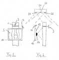
- a device according to the inventionis shown schematically, with the example can be inspected inside a joint of a patient.
- the Leg 1 of the patientshould be examined at the joint 5.
- the invention designed flat screen 10is held directly in front of the joint, and appears on the screen 10 then an image that contains both image information from the camera's video camera image 14 ( Figure 2) contains as well as image information about the internal anatomical structure, which be transmitted for example by radio transmission from a navigation device. Is to in advance of the patient or of his leg 1 a tomographic image (MR or CT scan) been created.
- MR or CT scantomographic image
- the camera 14is fixedly mounted on the back of the screen 10.
- This type of image displayis made possible by the fact that the position of the camera 14 or of the screen 10 in the space around the leg 1 of the patient by means of a tracking device is determined.
- This tracking deviceis in the present case an optical tracking device, namely a marker assembly 12 whose position by means of the schematic shown navigation system 20 is detected.
- the navigation system 20includes for this purpose For example, two spaced infrared cameras 24, 26 and an infrared light emitter 22. From the two images of the infrared camera 24, 26, the three-dimensional spatial position the marker assembly 12 and thus also the screen 10 and the permanently installed Camera 14 are determined. It is also possible the spatial position of the leg 1 by a determine corresponding marker assembly 3 in the room.
- the position of screen 10 and camera 14can in the following way the position of the current image plane are captured.
- the camera 14has a small one Aperture and a shallow depth of field, leaving only the image in a specific focal plane sharp. It can thereby determine the position of this image plane and on the Screen 10 transmitted an image from the CT or MR recording method, which also is just in this picture plane. It is important that the aspect ratio of the Video image is displayed in a 1: 1 scale to the slice image. If now with the device according to the invention the joint of a patient is considered, you can see for example, at the top and bottom of the screen, the contours of the patient's leg.
- This informationcan now be adapted to the image from the layer recording method be that it is just above the video image to ensure a realistic impression.
- the viewer of the screen 10can then display both on the screen View the video image, ie a real image, as well as the "inner” image from the film recording process, in each case in the desired depth and in each set transparency for both pictures.
- These settingsmay be via controllers, and others according to the invention Inputs (to be discussed in more detail below), such as one of them is indicated by the reference numeral 15.
- the device according to the inventionthus gives the viewer the opportunity for the first time in Looking directly at the patient in real time into the inner treatment area and plan or adjust the treatment accordingly. He has to look Do not turn away from the patient and onto a fixed navigation screen see what is particularly beneficial when the patient's reactions to certain medical measures should be checked. Since the "inner" images from the fluoroscopy or tomographic imaging techniques can be designed to virtually 3D views represent the inner body parts, the picture can be made very clear overall become.
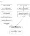
- FIG. 3until the picture overlay and for this special case, the sequence of a Method is shown, as it is carried out with the device according to the invention, In particular, this is the activity performed by the computer of the navigation system illuminated.
- the upper left side of the flowchartrelates to the processes of video capturing, while on the right side the image acquisition for the inside of the body explained using the example of MR / CT image acquisition.
- video capturingis First determines the focal plane, as previously explained. Thereafter, a Determining the distance of the focal plane to the camera, whereupon the camera uses its Tracking device is registered in the navigation system. It is now the determination of Space position of the camera relative to the navigation system known.
- the MR / CT image acquisitionthis will first be done in advance, then what The data obtained is a three-dimensional image reconstruction. Then the registration of the object, for example a patient's part of the body, performed in space, d. H. there is a determination of the relation of the object position in space to the MR / CT images. This can be realized by the spatial detection of a located on the object Marker assembly.
- a video image / MR / CT image matchingis now performed, i. H. the both images are computer-controlled in accordance with what the image position and the picture size is concerned.
- the MR / CT 3D imagescan be projected onto the video images be superimposed on the image display device and the attending physician at the Support diagnosis or treatment.
- DRRsDigitally Reconstructed Radiographs
- the portable one Flat screenserves as an artificial X-ray film, so to speak, that means the tracking or navigation system determines the position of the screen and knows the position of the screen Patients and can now send virtual "rays" through the patient, as at then lead an x-ray machine to an x-ray-like image. This preserves the user the ability to virtually hold an X-ray source in hand and out of all Viewing angles to obtain X-ray images.
- FIGS 4 and 5show a perspective view of an embodiment of the invention Device from the front and the back.
- the image display device 10has in this case a screen 16, which may be formed as a touch screen can.
- On the screen 16is the currently recorded video image of a patient to see and for example in the ear are patient-specific objects, namely internal structures 17 appears.
- the portable screen 10additionally has input buttons 15 which are arranged above the handle 18 and on the two-sided handles.
- the camera 14is recessed in the center of the device.
- Emgabeknöpfen 15 and / or with the touch screen 16 inputscan now made which are the device of the invention to a multifunctional device used in treatment planning or treatment support can.
- the device 10is e.g. by radio with a usual treatment support, not shown here. or treatment planning system connected to exchange data.
- the following activitiescan be carried out individually or in combination become:
- Illustrated objectscan be turned on or off, i. they become visible or made invisible. Parameters of displayed objects can be changed, for example the color, the transparency etc .. It can be zoomed in and out, and the Brightness or contrast can be controlled on the screen. Objects can be marked or be selected and moved, for example, for planning or modification a treatment plan. Landmarks or measuring routes can be set. It is possible to save screenshots of the image representation or to the documentation images to ship. Movies from multiple captured images can be played, started or be stopped.
- the working distancecan be changed, i. the "virtual depth of field" being set becomes, at which distance objects are visible.
- the input means 15, 16can be used to control other devices, e.g. Navigation system, Treatment robot, microscope, C-arm, ultrasound, room light, etc. can be used.
- the imagecan be frozen, especially while the instruments continue to navigate and be projected on.
- a difference of two or more images, preferably as before / after picturecan be displayed on an input; also can have an undo / redo function
- Panoramic imagescan be generated, for example, a complete, longer patient's part of the body to depict (leg).
- the image display devicecan be used as a smart digital camera, also video camera for documentation purposes can be used and extension sets are conceivable, for example Provide help from datastores or the Internet.
- objectsis in the context of the invention quite generally a wide variety understand image data information about actual physical objects, but also about virtual image information material.
- object informationcan obtained from patient-specific, two-dimensional or three-dimensional data which come, for example, from image acquisition techniques, such as CT, MR, more functional MR, ultrasound, PET, SPECT, radiographs etc. It is also possible, model-based To use data, so without working data of the current patient.
- bonescome into question (long bones, skulls, bone pieces MKG etc.), but also soft tissues (brain, ligaments, fluids etc.).
- This datacan then be in the Size can be adjusted or be from a set of existing data or existing Objects matching the selected.
- implantship, knee, teeth, intramedullary nails, screws, plates
- implants in the spinal regionimplants in the spinal region
- implants in the spinal regionimplants in the spinal region
- implants in the spinal regionimplants in the spinal region
- the implantsmay also be selected from predetermined sizes and used virtually on the image display device to see which implant fits best where and what the result looks like.
- the objectsmay of course include registration markers and instruments (endoscope, saw, drill, awl, etc.).
- implantsskin, bones
- fastenerssuch as tie rods can usually be bent by hand and adjusted, under the control of the image display device and with the information be virtually matched across the patient, i. be planned. It then becomes in view of the anatomy of the patient already determines the correct form of the fastening element, which can then be made this way. A time-consuming adaptation to open patients is no longer necessary.
- markscan be made on this touch screen or markings are made, which, for example, in the craniotomy and for Electrodes may be advantageous.
- Another field of applicationrelates to the adaptation of image acquisition data, for example previously recorded by the patient by CT, MR or similar procedures.
- the Video camera of the image display devicefor example, textures of the patient as a video image record and thus improve the data from the image capture or "beautify" ,
- CT or MR tomographic imagesare not very good Patient surface structures. These surface structures are but from the video image known and can complement the layer image data. This can be done in plastic surgery the planning of interventions and in particular the visual pre-simulation of results These interventions are of great advantage.
- the brightness of the video imagecan be used to adjust the appearance of the object, and in another embodiment, the possibility exists of the image display device directly on the imaging device for the internal structures of the patient (CT, MR, fMRI, etc.), so that an assignment or registration of the different image data is simplified.
Landscapes
- Health & Medical Sciences (AREA)
- Life Sciences & Earth Sciences (AREA)
- Engineering & Computer Science (AREA)
- Medical Informatics (AREA)
- Surgery (AREA)
- Public Health (AREA)
- Heart & Thoracic Surgery (AREA)
- Veterinary Medicine (AREA)
- Nuclear Medicine, Radiotherapy & Molecular Imaging (AREA)
- General Health & Medical Sciences (AREA)
- Animal Behavior & Ethology (AREA)
- Molecular Biology (AREA)
- Biomedical Technology (AREA)
- Radiology & Medical Imaging (AREA)
- Biophysics (AREA)
- Physics & Mathematics (AREA)
- Pathology (AREA)
- Optics & Photonics (AREA)
- High Energy & Nuclear Physics (AREA)
- Pulmonology (AREA)
- Human Computer Interaction (AREA)
- Theoretical Computer Science (AREA)
- Robotics (AREA)
- Computer Vision & Pattern Recognition (AREA)
- Measuring And Recording Apparatus For Diagnosis (AREA)
- Image Processing (AREA)
- Apparatus For Radiation Diagnosis (AREA)
Abstract
Description
Translated fromGermanDie Erfindung betrifft die Visualisierung für kombinierte Patienten- und Objektbilddaten inSystemen, wo Patientenbilddaten oder Objektbilddaten auf Videobilder projiziert werden.The invention relates to the visualization for combined patient and object image data inSystems where patient image data or object image data is projected onto video images.
Grundsätzlich weisen Vorrichtungen dieser Gattung eine Bildanzeigeeinrichtung, mindestenseine Videokamera und ein computergestütztes Navigationssystem auf, das die Raumpositionender Anzeigevorrichtung und/oder der Videokamera sowie die Raumpositionen eines Patientenkörperteilsüber dort angebrachte Trackingeinrichtungen erfassen kann. Die Vorrichtungendienen dazu, einen Mediziner bei der Diagnose bzw. bei der Behandlung eines Patientenvisuell zu unterstützen. Es soll die Möglichkeit geschaffen werden, Bilder aus dem Innerendes Patienten mit herkömmlichen Videobildern zu verknüpfen, um Behandlung und Diagnosezu erleichtern.Basically, devices of this type have an image display device, at leasta video camera and a computerized navigation system that displays the spatial positionsthe display device and / or the video camera and the spatial positions of a patient's body partcan detect there attached tracking devices. The devicesserve to help a physician diagnose or treat a patientvisually support. It should be possible to create pictures from the insideof the patient to associate with conventional video images to treatment and diagnosisto facilitate.
Ein gattungsgemäßes, videobasiertes chirurgisches Zielsystem ist aus der US-A-5,765,561bekannt, wobei unter anderem die Verwendung einer getrackten Videokamera vorgeschlagenwird, deren Bilder auf dem stationär angeordneten Bildschirm eines Navigationssystems mitzugeordneten Bildern aus Durchleuchtungs- bzw. Schichtbilderfassungsverfahren überlagertwerden. Auch die US 5,715,836 beschreibt die Überlagerung von Bildern aus verschiedenenQuellen in einer Operations- bzw. Behandlungsumgebung. Die Bilder können aus der Computertomographie,Kernspintomographie, aus Ultraschall- oder Röntgenbildgeräten stammen.Auch hier werden die Bilder aber auf einem stationären Bildschirm ausgegeben.A generic, video-based surgical targeting system is known from US-A-5,765,561known, among other things, the use of a tracked video camera proposedwhose pictures on the stationary screen of a navigation system withsuperimposed associated images from fluoroscopy or slice imagingbecome. Also US 5,715,836 describes the superposition of images from differentSources in a surgical or treatment environment. The images can be taken from computed tomography,Magnetic resonance tomography, from ultrasound or X-ray imaging devices.Again, the images are displayed on a stationary screen.
Eine Positionsverifizierung für Positionsmarkierungen in einem Videokamerabild, bei derVideokameras und Infrarotkameras kombiniert und deren Bilder überlagert werden, ist ausder DE 19 848 765 A1 bekannt. Auch hier werden die Bilder auf einem stationären Bildschirmausgegeben.A position verification for position marks in a video camera image, in whichVideo cameras and infrared cameras combined and their images are superimposed is offDE 19 848 765 A1 discloses. Again, the pictures are on a stationary screenoutput.
Nachteilig an den oben beschriebenen Ausführungsformen ist insbesondere, dass der Arzt, derdie Bilder betrachten möchte, immer wieder vom Patienten weg und zum Bildschirm des Navigationssystemshinblicken muss. Dabei kann er nicht mehr genau darauf achten, in welcherStellung nun die Kamera steht, also von welcher Außenposition genau er die überlagertenBilder erhält. Das System ist deshalb umständlich und ermöglicht keinen direkten Einblick inden Patientenkörperteil. Ferner müssen alle Eingaben, die der Arzt in das System zu tätigengedenkt, an der Eingabestation des Navigationssystems bzw. des Behandlungsplanungssystemsgemacht werden. Dabei muss sich der Arzt wiederum vom Patienten abwenden, und erkann die Wirkung der Eingaben nicht unmittelbar überprüfen.A disadvantage of the embodiments described above is in particular that the doctor wholooking at the pictures, again and again away from the patient and to the screen of the navigation systemmust look. He can no longer pay close attention to whichPosition now the camera is, so from which external position exactly he superimposedReceives pictures. The system is therefore cumbersome and does not allow direct insight intothe patient's part of the body. Furthermore, all the inputs that the doctor must make into the systemat the input station of the navigation system or the treatment planning systembe made. The doctor must turn away from the patient, and hecan not immediately check the effect of the inputs.
Es ist die Aufgabe der vorliegenden Erfindung, eine Vorrichtung bzw. ein Verfahren zur visuellenKombination von Patientenbilddaten aus Durchleuchtungs- bzw. Schichtbilderfassungsverfahrenbzw. Objektbilddaten mit Videobildern bereitzustellen, welche die oben genanntenNachteile des Standes der Technik überwinden. Insbesondere soll es ermöglicht werden,direkt und unmittelbar in Ansicht des Patienten gewünschte Bildinformationen zu erhaltenund dabei auch Einfluss auf die Behandlungsunterstützung auszuüben.It is the object of the present invention, a device or a method for visualCombination of patient image data from fluoroscopy or slice imagingor to provide object image data with video images which are the aboveOvercome the disadvantages of the prior art. In particular, it should be possibledirectly and immediately to obtain desired image information in view of the patientand to exert influence on the treatment support.
Diese Aufgabe wird dadurch gelöst, dass eine erfindungsgemäße Vorrichtung so ausgestaltetist, dass die Bildanzeigevorrichtung und die Videokamera einander zugeordnet und als tragbareEinheit ausgebildet sind, und an der Bildanzeigevorrichtung eine Eingabevorrichtung vorgesehenist, welche Eingaben für eine bildunterstützte Behandlung oder Behandlungsplanungermöglicht.This object is achieved in that a device according to the invention designedis that the image display device and the video camera associated with each other and as portableUnit are formed, and provided on the image display device, an input deviceis what inputs for image assisted treatment or treatment planningallows.
Vorteilhafterweise ergibt sich dabei die Möglichkeit für den behandelnden Arzt, die Bildanzeigevorrichtungselbst mit zugeordneter Kamera vor das Patientenkörperteil zu halten unddamit in unmittelbarem Aufblick auf den Patienten die gewünschten anatomischen Informationenauszulesen. Mit der erfindungsgemäßen Vorrichtung wird alleine durch die Zuordnungund Ausbildung von Videokamera und Bildanzeigevorrichtung als tragbare Einheit, ein weitererSchritt in die Richtung getan, einen "gläsernen Patienten" zu schaffen, wobei die Bildanzeigevorrichtunglediglich vor das in Frage kommende Patientenkörperteil gehalten werdenmuss. Da die Kamerazuordnung zur Bildanzeigevorrichtung über die Trackingeinrichtungverfolgt wird, ist die Position der betrachteten Elemente immer bekannt, und das Navigationssystemhat Informationen darüber, wie und aus welcher Richtung der Patientenkörperteil angesehen wird. Insbesondere bei der Durchführung minimal invasiver Eingriffe, bei denen keineFreilegung des Eingriffsgebietes erfolgt, bietet die erfindungsgemäße Vorrichtung somitdie Möglichkeit für den behandelnden Arzt, sich während der Operation nochmals genau überdie Lage der Anatomieteile des Patienten bzw. anderer Objekte im Verhältnis zur Patientenanatomiein Kenntnis zu setzen. Auf der Bildanzeigevorrichtung können dabei natürlich auchgetrackte, bzw. navigierte Instrumente angezeigt werden. Der Arzt muss seinen Blick nichtmehr von dem Patienten abwenden, um in erfindungsgemäßer Weise in das Innere des Patientenkörpershineinzusehen.Advantageously, this results in the possibility for the attending physician, the image display deviceeven with assigned camera to hold in front of the patient's body part andthus, looking directly at the patient, the desired anatomical informationread. With the device according to the invention is alone by the assignmentand forming a video camera and image display device as a portable unit, anotherStep in the direction to create a "transparent patient", using the image display deviceare held only in front of the candidate patient's part of the bodygot to. Since the camera assignment to the image display device via the tracking deviceis tracked, the position of the considered elements is always known, and the navigation systemhas looked at information on how and from what direction the patient's part of the bodybecomes. In particular, when performing minimally invasive procedures in which noExposure of the intervention area, the device according to the invention thus providesthe opportunity for the attending physician, over again during the operation overthe position of the anatomy parts of the patient or other objects in relation to the patient's anatomyto inform. On the image display device can of course alsotracked or navigated instruments are displayed. The doctor does not have his eyesTurn away from the patient to in accordance with the invention in the interior of the patient's bodylook into it.
Hinzu kommt noch der Vorteil, dass der Arzt durch die Erfindung dazu in die Lage versetztwird, in direkter und unmittelbarer Ansicht des Patienten und mit Hilfe der Informationen ausder Bildanzeige über die Eingabevorrichtung noch Änderungen und Modifikationen vorzunehmen,die seine Arbeit unterstützen. Er kann dann die Wirkung seiner Modifikationen unmittelbarund in Ansicht des Patienten überprüfen, ohne sich vorher einer Eingabestation zuwendenzu müssen, was die Verifizierung oder Korrektur bestimmter Maßnahmen sehr vereinfachtund unmittelbarer gestaltet.In addition, there is the advantage that the doctor is enabled by the invention to the situationis made, in direct and immediate view of the patient and with the help of informationto make changes and modifications to the image display via the input devicewho support his work. He can then immediately the effect of his modificationsand check in view of the patient without first turning to an input stationwhich makes the verification or correction of certain measures much easierand designed more directly.
Bei einer bevorzugten Ausführungsform der Erfindung weist die Eingabevorrichtung elektromechanischeSchalter auf. Diese Schalter können von jeder bekannten Art sein; vorstellbarsind Druckschalter, Richtungsdruckschalter, aber auch joystickartige Schalter, integriert oderkombiniert mit Druckschaltern. Es können mehrere Eingabevorrichtungen der vorher genanntenArten vorhanden sein. Möglich ist es ebenfalls, die Eingabevorrichtung zusätzlichoder alleine als Touchscreen auszubilden. Natürlich sind alle möglichen Eingabevorrichtungenrealisierbar, auch fortgeschrittene wie Spracheingaben usw..In a preferred embodiment of the invention, the input device comprises electromechanicalSwitch on. These switches can be of any known type; imaginableare pressure switches, directional pressure switches, but also joystick-type switches, integrated orcombined with pressure switches. There may be several input devices of the aforementionedSpecies exist. It is also possible, the input device in additionor to train alone as a touch screen. Of course, all possible input devicesfeasible, even advanced as voice inputs, etc ..
Gemäß einer bevorzugten Ausgestaltung der erfindungsgemäßen Vorrichtung ist dieser eincomputergestütztes Behandlungsplanungs- und -unterstützungssystem zugeordnet, das Eingabender Eingabevorrichtung verarbeitet. Die tragbare Einheit aus Bildanzeigevorrichtung undVideokamera wird dadurch zu einem Teil des Behandlungsplanungssystems sowie der Behandlungsunterstützungund erspart entsprechende separate Eingaben an separat dafür vorgesehenenSystemvorrichtungen.
Die erfindungsgemäße Vorrichtung kann eine kabelgestützte oder kabellose Datenübertragungzwischen Bildanzeigevorrichtung und dem computergestützten Behandlungsplanungsund Unterstützungssystem aufweisen, mittels der vorzugsweise auf eine Eingabe hin Objektinformationenübertragen werden. Solche Objektinformationen können sämtliche Arten vonBildinformationen umfassen, und die Übertragung kann in beiden Richtungen zum Informationsaustauschbzw. Abgleich erfolgen.According to a preferred embodiment of the device according to the invention, this is associated with a computer-aided treatment planning and support system, which processes inputs of the input device. The portable unit of image display device and video camera thereby becomes part of the treatment planning system as well as the treatment support and saves corresponding separate inputs on separately provided system devices.
The device according to the invention may comprise a cable-based or wireless data transmission between the image display device and the computer-aided treatment planning and support system, by means of which object information is preferably transmitted in response to an input. Such object information may include all sorts of image information, and the transmission may be bidirectional for information exchange.
Die Erfindung betrifft ferner ein Verfahren zur visuellen Kombination von Patientenbilddatenaus Durchleuchtungs- bzw. Schichtbilderfassungsverfahren bzw. Objektbilddaten mit Videobildemauf einer Bildanzeigeeinrichtung, der mindestens eine Videokamera zugeordnet ist,bei dem ein computergestütztes Navigationssystem der Bildanzeigevorrichtung und/oder derVideokamera sowie die Raumpositionen eines Patientenkörperteils über dort angebrachteTrackingeinrichtungen erfasst, wobei die Bildanzeigevorrichtung und die Videokamera alstragbare Einheit ausgebildet sind, und bei dem Eingaben für eine bildunterstützte Behandlungoder Behandlungsplanung mittels einer Eingabevorrichtung an der Bildanzeigevorrichtungeingegeben werden. Die Vorteile des erfindungsgemäßen Verfahrens umfassen diejenigen,die oben im Hinblick auf die erfindungsgemäße Vorrichtung beschrieben wurden.The invention further relates to a method for the visual combination of patient image datafrom transillumination or slice image acquisition techniques or object image data with video imageson an image display device associated with at least one video camera,in which a computer-aided navigation system of the image display device and / or theVideo camera as well as the spatial positions of a patient's body part over there mountedTracking devices detected, the image display device and the video camera asare formed portable unit, and in the inputs for a picture-assisted treatmentor treatment planning by means of an input device on the image display devicebe entered. The advantages of the method according to the invention include thosewhich have been described above with regard to the device according to the invention.
Bei einer Ausführungsform des Verfahrens gemäß der Erfindung wird ein computergestütztesBehandlungsplanungs- und -unterstützungssystem die Eingaben der Eingabevorrichtung verarbeiten.Dabei können behandlungsunterstützende Objekt- bzw. Bildinformationen über einekabelgestützte oder kabellose Datenübertragung zwischen Bildanzeigevorrichtung und demcomputergestützten Behandlungsplanungs- und -unterstützungssystem übertragen werden. ImEinzelnen können die Objekt- bzw. Bildinformationen eine oder mehrere der folgenden Informationenumfassen:
- Informationen über patientenspezifische, aus zwei- oder dreidimensionalen Bilddatengewonnene Teile des Patientenkörpers,
- Informationen über nicht patientenspezifische, modellbasierte Objektdaten, insbesonderegenerische oder angepasste generische Körperteile, wie Knochen oder Weichteile,
- Informationen über Implantate,
- Messinformationen,
- Informationen über Medikamente, und speziell deren Verteilung, auch simulierte Verteilung,
- Informationen über Radiochirurgie- bzw. Strahlentherapiepläne,
- Informationen über Pläne zur bildgestützten Chirurgie,
- Informationen über Registrierungsmarker,
- Informationen über Instrumente,
- künstlich aus Bilddateninformationen erzeugte Röntgenbilder (DRRs = Digitally ReconstructetRadiographs) bzw. Informationen aus tatsächlichen Röntgenbildern.
- Information about patient-specific parts of the patient's body obtained from two- or three-dimensional image data,
- Information about non-patient-specific, model-based object data, in particular generic or adapted generic body parts, such as bones or soft tissues,
- Information about implants,
- Measurement information,
- Information about medications, and especially their distribution, also simulated distribution,
- Information about radiosurgery or radiotherapy plans,
- Information about plans for image-guided surgery,
- Information about registration markers,
- Information about instruments,
- artificially generated from image data information X-ray images (DRRs = Digitally Reconstructed Radiographs) or information from actual X-ray images.
Ein erfindungsgemäßes Verfahren kann so ausgestaltet sein, dass behandlungsunterstützendeBild- bzw. Objektdaten oder Behandlungspläne durch Eingaben an der Eingabevorrichtunggeändert oder angepasst werden. Ferner kann die Bilddarstellung an der Bildanzeigeeinrichtungdurch solche Eingaben geändert oder angepasst werden.A method according to the invention can be designed such that treatment-supportingImage or object data or treatment plans through inputs to the input devicebe changed or adapted. Furthermore, the image representation on the image display devicebe changed or adjusted by such input.
Gemäß einer weiteren Ausführungsform werden durch Planung vorhergesagte Änderungenam Patientenkörper durch Eingaben an der Eingabevorrichtung auf der Bildanzeigevorrichtungangezeigt. Dies ermöglicht eine unmittelbare Kontrolle der Planung in unmittelbarerAnsicht des Patientenkörperteils.According to another embodiment, predicted changes are made by planningon the patient's body by inputs to the input device on the image display devicedisplayed. This allows for immediate control of planning in the immediateView of the patient's body part.
Eine weitere Ausführungsform des erfindungsgemäßen Verfahrens zeichnet sich dadurch aus,dass durch Eingaben an der Eingabevorrichtung Bilder auf der Bildanzeigevorrichtung gespeichert,kombiniert, zu Bildsequenzen oder Filmen zusammengefügt, versendet, abgespielt,voneinander subtrahiert oder mit Kommentaren versehen werden, wobei diese Tätigkeiteneinzeln oder in jedweder Kombination durchgeführt werden können.A further embodiment of the method according to the invention is characterizedthat images are stored on the image display device by inputs to the input device,combined, merged into sequences of images or movies, sent, played,be subtracted from each other or provided with comments, these activitiesindividually or in any combination can be performed.
In besonders vorteilhafter Ausführung werden durch Eingabe an der Eingabevorrichtung andereGeräte in der Behandlungsumgebung gesteuert.In a particularly advantageous embodiment, by input to the input device otherControlled devices in the treatment environment.
Es ist möglich, die Integration der Bildanzeigeeinrichtung durch ihre direkte Anbringung anein Bilderfassungsgerät für das computergestützte Behandlungsplanungs- und -unterstützungssystemdurchzuführen.It is possible to integrate the image display device by its direct attachmentan image acquisition device for the computer-aided treatment planning and support systemperform.
Allgemeine Ausführungsvarianten für die erfindungsgemäße Vorrichtung werden im Folgendenerläutert. Die Videokamera kann auf der Rückseite der Bildanzeigevorrichtung angeordnetsein. Dabei entsteht ein kompaktes Gerät; die Kamera kann vollständig aus dem Blickbereichdes Benutzers herausgenommen werden. Grundsätzlich ist anzumerken, dass die Kameraan jeder Stelle der Rückseite der Bildanzeigevorrichtung angebracht oder in dieser integriert sein kann, z.B. auch im Randbereich der Bildanzeigevorrichtung. Die Videokamera stehtbevorzugt in vorbestimmter bzw. systembekannter räumlicher Zuordnung zur Bildanzeigevorrichtung,und die Trackingeinrichtung ist an der Bildanzeigevorrichtung angeordnet. Durchdie vorbestimmte bzw. systembekannte räumliche Zuordnung von Videokamera und Bildanzeigevorrichtungwird die Möglichkeit eröffnet, nur eines dieser beiden Geräte mittels derTrackingeinrichtung zu verfolgen, da man immer genau weiß, wo sich dann das andere Gerätbefindet. Es steht dem Konstrukteur dann frei, die Trackingeinrichtung entweder an der Bildanzeigevorrichtungselbst oder an der Videokamera anzuordnen, je nachdem wie diese Trackingeinnchtungam Besten vom Navigationssystem erfasst werden kann. Bei optisch basiertenNavigationssystemen kann die Trackingeinrichtung eine reflektierende oder aktiv abstrahlendeMarkeranordnung sein, während es natürlich im Rahmen der vorliegenden Erfindungauch möglich ist, die Navigation über ein Magnettrackingsystem durchzuführen, beidem Spulen in einem erzeugten Magnetfeld verfolgt werden. Was die Navigations- bzw. Trackingsystemebetrifft, die mit reflektierenden Markeranordnungen arbeiten, so sind solcheeinsetzbar, die mit unsichtbarem Licht (z. B. Infrarot) und einer entsprechenden Lichtquellearbeiten, aber auch solche, die eine Videotechnologie verwenden, die mit sichtbarem Licht(Raumlicht) arbeitet. Letztere Systeme verwenden optische Marker, die sichtbares Licht reflektieren,wobei die Analyse der Markerkennung jedoch ausschließlich im Videobild vorgenommenwird.General embodiments for the device according to the invention are hereinafterexplained. The video camera can be placed on the back of the image display devicebe. This creates a compact device; the camera can be completely out of sighttaken out of the user. Basically, it should be noted that the cameraattached to any part of the back of the image display device or integrated in thismay be, e.g. also in the edge region of the image display device. The video camera is stoppedpreferably in a predetermined or system-known spatial assignment to the image display device,and the tracking device is disposed on the image display device. Bythe predetermined or system-known spatial allocation of video camera and image display deviceopens the possibility, only one of these two devices by means ofTrack tracking device, because you always know exactly where then the other devicelocated. The designer is then free to use the tracking device either on the image display deviceyourself or on the video camera, depending on how this tracking devicecan best be detected by the navigation system. With optically basedNavigation systems, the tracking device can be a reflective or active radiatingWhile it is of course within the scope of the present inventionIt is also possible to perform the navigation via a magnetic tracking system atthe coils are tracked in a generated magnetic field. What the navigation or tracking systemswhich work with reflective marker arrays, such arecan be used with invisible light (eg infrared) and a corresponding light sourcework, but also those who use a video technology with visible light(Room light) works. The latter systems use optical markers that reflect visible light,However, the analysis of the mark detection made only in the video imagebecomes.
Die Bildanzeigevorrichtung ist leicht und gut handhabbar auszugestalten, indem sie als tragbarerFlachbildschirm, insbesondere LCD-Flachbildschirm konstruiert wird. Dieser Schirmkann natürlich, wie vorher bemerkt, die Touchscreen-Funktion aufweisen. Die Energieversorgungder erfindungsgemäßen Vorrichtung kann durch eigene Energieversorgung (Batteriebzw. Akku) oder über Kabel erfolgen. Falls eine drahtlose, insbesondere Funkübertragung fürdie Daten verwendet wird, eignet sich besonders eine eigene Energieversorgung für die Vorrichtung,damit die weitgehendste Handhabungsfreiheit erreicht wird.The image display device is lightweight and easy to handle, making it more portableFlat screen, especially LCD flat screen is constructed. This screencan, of course, as previously noted, have the touch screen function. The energy supplythe device according to the invention can by its own power supply (batteryor battery) or via cable. If a wireless, in particular radio transmission forthe data is used, is particularly suitable for its own power supply for the device,so that the most extensive handling freedom is achieved.
Die Videokamera kann eine kleine Blende und eine geringe Schärfentiefe aufweisen, damitnur ein kleiner Bereich des erfassten Bildes in der Fokalebene liegt. Mit einer solchen Kameraist es möglich, den Abstand zwischen dem Bild und der Fokalebene zu ermitteln. Wenn dieRaumposition der Kamera aus dem Navigationssystem her bekannt ist und der Abstand zurBildebene ebenfalls bekannt ist, kann das dem Navigationssystem angeschlossene Computersystem die räumliche Position des Videobildes in Echtzeit errechnen. Damit wird eine Zuordnungvon Videobild und Bilddaten aus einer vorher durchgeführten Durchleuchtungs- bzw.Schichtbilderfassung optimal möglich, ebenso wie die Zuordnung von Objektdaten.The video camera may have a small aperture and a shallow depth of field with itonly a small portion of the captured image lies in the focal plane. With such a camerait is possible to determine the distance between the image and the focal plane. If theSpace position of the camera is known from the navigation system ago and the distance to theImage plane is also known, the computer system connected to the navigation systemcalculate the spatial position of the video image in real time. This will be an assignmentof video image and image data from a previously performed fluoroscopy orLayer image acquisition optimally possible, as well as the assignment of object data.
Die zu überlagernden einzelnen Bilddaten bzw. Objektdaten werden vorteilhafterweise ingrößerer Position auf der Bildanzeigevorrichtung so angepasst, dass eine korrekte bzw. gewünschteGrößenzuordnung entsteht, also zum Beispiel eine 1:1 Darstellung der Bilder inÜberdeckung. Im Navigationssystem bzw. im Behandlungsplanungs- und -unterstützungssystem,welches als ein Teil des Navigationssystems oder separat und diesem zugeordnet zurVerfügung gestellt werden kann, kann eine Konturen-Matching-Einheit bereitgestellt werden,mittels der die Überdeckung der dargestellten Bilddaten realisiert wird, insbesondere über einAußenkonturen-Matching für den Patientenkörperteil.The superimposed individual image data or object data are advantageously ingreater position on the image display device adapted so that a correct or desiredSize allocation arises, so for example a 1: 1 representation of the pictures inCoverage. In the navigation system or in the treatment planning and support system,which as a part of the navigation system or separately and associated with thisCan be provided, a contour matching unit can be providedby means of which the overlapping of the displayed image data is realized, in particular via aOuter contour matching for the patient's part of the body.
An der Kamera bzw. in deren Umgebung an der Bildanzeigevorrichtung ist vorteilhafterweiseeine Beleuchtungsvorrichtung für den Patientenkörperteil vorgesehen, speziell beispielsweiseals Ringlicht (LEDs, Lampen, Leuchtstoffröhren).At the camera or in the vicinity of the image display device is advantageouslya lighting device for the patient's body part provided, especially for exampleas ring light (LEDs, lamps, fluorescent tubes).
Die Erfindung wird im Weiteren anhand einer Ausführungsform näher erläutert. In den hierzubereitgestellten Zeichnungen zeigen:
- Figur 1
- eine schematische Darstellung für die Verwendung einer erfindungsgemäßenVorrichtung zur Ansicht eines Patienten-Kniegelenks in der Aufsicht;
- Figur 2
- eine seitliche Ansicht der Vorrichtung nach Figur 1 mit schematisch dargestelltemNavigationssystem;
Figur 3- ein Ablaufdiagramm für den Betrieb der erfindungsgemäßen Vorrichtung,und
- Figur 4 und 5
- perspektivische Vorder- und Rückansicht einer erfindungsgemäßen Vorrichtung.
- FIG. 1
- a schematic representation of the use of a device according to the invention for viewing a patient's knee joint in the supervision;
- FIG. 2
- a side view of the device of Figure 1 with schematically illustrated navigation system;
- FIG. 3
- a flow chart for the operation of the device according to the invention, and
- FIGS. 4 and 5
- perspective front and rear view of a device according to the invention.
In der Figur 1 ist schematisch eine erfindungsgemäße Vorrichtung dargestellt, mit der beispielsweisein das Innere eines Gelenks eines Patienten Einsicht genommen werden kann. DasBein 1 des Patienten soll am Gelenk 5 untersucht werden. Hierzu wird der erfindungsgemäßausgestaltete Flachbildschirm 10 direkt vor das Gelenk gehalten, und auf dem Schirm 10 erscheint dann ein Bild, das sowohl Bildinformationen aus dem Videokamerabild der Kamera14 (Figur 2) enthält als auch Bildinformationen über die innere anatomische Struktur, welchebeispielsweise per Funkübertragung von einem Navigationsgerät übermittelt werden. Dazu istvorab von dem Patienten bzw. von dessen Bein 1 eine Schichtbildaufnahme (MR- oder CT-Aufnahme)erstellt worden.In the figure 1, a device according to the invention is shown schematically, with the examplecan be inspected inside a joint of a patient. TheLeg 1 of the patient should be examined at the
Wie besser in Figur 2 deutlich wird, befindet sich die Kamera 14 fest angebracht an der Rückseitedes Bildschirms 10.As better shown in Figure 2, the
Möglich wird diese Art der Bilddarstellung dadurch, dass die Position der Kamera 14 bzw.des Bildschirms 10 im Raum um das Bein 1 des Patienten herum mittels einer Trackingeinrichtungermittelt wird. Diese Trackingeinrichtung ist im vorliegenden Fall eine optische Trackingeinrichtung,nämlich eine Markeranordnung 12, deren Position mittels des schematischdargestellten Navigationssystems 20 erfasst wird. Das Navigationssystem 20 umfasst hierzubeispielsweise zwei beabstandete Infrarot-Kameras 24, 26 und einen Infrarot-Lichtabstrahler22. Aus den beiden Bildern der Infrarot-Kamera 24, 26 kann die dreidimensionale Raumpositionder Markeranordnung 12 und damit auch des Bildschirms 10 und der fest installiertenKamera 14 ermittelt werden. Es ist ferner möglich die Raumposition des Beines 1 durch eineentsprechende Markeranordnung 3 im Raum zu ermitteln.This type of image display is made possible by the fact that the position of the
Wenn nun die Position von Bildschirm 10 und Kamera 14 bekannt ist, kann in folgender Weisedie Position der aktuellen Bildebene erfasst werden. Die Kamera 14 hat nämlich eine kleineBlende und eine geringe Schärfentiefe, so dass nur das Bild in einer bestimmten Fokalebenescharf erscheint. Es lässt sich hierdurch die Position dieser Bildebene ermitteln und auf demBildschirm 10 ein Bild aus dem CT- oder MR-Aufnahmeverfahren übertragen, welche ebenfallsgerade in dieser Bildebene liegt. Wichtig ist hierbei, dass das Abbildungsverhältnis desVideobildes in einem 1: 1-Maßstab zum Schichtaufnahmebild angezeigt wird. Wenn nun mitder erfindungsgemäßen Vorrichtung das Gelenk eines Patienten betrachtet wird, sieht manbeispielsweise am oberen und unteren Bildschirmrand die Konturen des Patientenbeines. Mitdieser Information kann nunmehr das Bild aus dem Schichtaufnahmeverfahren so angepasstwerden, dass es gerade über dem Videobild liegt, um einen realistischen Eindruck zu gewährleisten.Der Betrachter des Bildschirms 10 kann dann auf dem Bildschirm sowohl dasVideobild, also ein echtes Bild, ansehen, als auch das "innere" Bild aus dem Schichtaufnahmeverfahren, und zwar in jeweils gewünschter Tiefe und in jeweils eingestellter Transparenzfür beide Bilder. Diese Einstellungen können über Steuerungsorgane, und andere erfindungsgemäßeEingaben (die weiter unten genauer erörtert werden) getroffen werden, wie eines davonmit dem Bezugszeichen 15 angedeutet ist.Now that the position of
Die erfindungsgemäße Vorrichtung gibt damit dem Betrachter erstmals die Möglichkeit, indirektem Aufblick auf den Patienten in Echtzeit in den inneren Behandlungsbereich hineinzusehenund die Behandlung entsprechend zu planen oder anzupassen. Er muss seinen Blicknicht mehr vom Patienten abwenden und auf einen fest installierten Navigationsbildschirmsehen, was insbesondere von Vorteil ist, wenn die Reaktionen des Patienten auf bestimmteärztliche Maßnahmen überprüft werden sollen. Da die "inneren" Bilder aus den Durchleuchtungs-bzw. Schichtbildaufnahmeverfahren so gestaltet werden können, dass sie virtuell 3-D-Ansichtender inneren Körperteile darstellen, kann das Bild insgesamt sehr anschaulich gemachtwerden.The device according to the invention thus gives the viewer the opportunity for the first time inLooking directly at the patient in real time into the inner treatment areaand plan or adjust the treatment accordingly. He has to lookDo not turn away from the patient and onto a fixed navigation screensee what is particularly beneficial when the patient's reactions to certainmedical measures should be checked. Since the "inner" images from the fluoroscopyor tomographic imaging techniques can be designed to virtually 3D viewsrepresent the inner body parts, the picture can be made very clear overallbecome.
Obwohl also nicht vor Ort ein Durchleuchtungs- bzw. Schichtbild aufgenommen wird, entstehtsomit ein virtuell "gläserner Patient".Thus, although a fluoroscopic or slice image is not recorded on site, arisesthus a virtual "glass patient".
In der Figur 3 ist, bis zur Bildüberlagerung und für diesen speziellen Fall, der Ablauf einesVerfahrens aufgezeigt, wie es mit der erfindungsgemäßen Vorrichtung durchgeführt wird,insbesondere wird hierbei die vom Computer des Navigationssystems durchgeführte Tätigkeitbeleuchtet. Die obere linke Seite des Ablaufdiagramms betrifft die Vorgänge bei der Videobilderfassung,während auf der rechten Seite die Bilderfassung für das Körperinnere erläutertwird, und zwar am Beispiel einer MR-/CT-Bilderfassung. Bei der Videobilderfassung wirdzunächst die Fokalebene bestimmt, wie dies vorher schon erläutert wurde. Danach erfolgt eineBestimmung des Abstandes der Fokalebene zur Kamera, worauf die Kamera mittels ihrerTrackingeinrichtung im Navigationssystem registriert wird. Es ist nun die Bestimmung derRaumposition der Kamera gegenüber dem Navigationssystem bekannt.In FIG. 3, until the picture overlay and for this special case, the sequence of aMethod is shown, as it is carried out with the device according to the invention,In particular, this is the activity performed by the computer of the navigation systemilluminated. The upper left side of the flowchart relates to the processes of video capturing,while on the right side the image acquisition for the inside of the body explainedusing the example of MR / CT image acquisition. When video capturing isFirst determines the focal plane, as previously explained. Thereafter, aDetermining the distance of the focal plane to the camera, whereupon the camera uses itsTracking device is registered in the navigation system. It is now the determination ofSpace position of the camera relative to the navigation system known.
Was die MR-/CT-Bilderfassung betrifft, so wird diese zunächst vorab erfolgen, worauf ausden erhaltenen Daten eine dreidimensionale Bildrekonstruktion erfolgt. Dann wird die Registrierungdes Objektes, beispielsweise eines Patientenkörperteils, im Raum durchgeführt, d. h.es erfolgt eine Bestimmung der Relation der Objektposition im Raum zu den MR-/CT-Bildern. Realisiert werden kann dies durch die räumliche Erfassung einer am Objekt befindlichenMarkierungsanordnung.As for the MR / CT image acquisition, this will first be done in advance, then whatThe data obtained is a three-dimensional image reconstruction. Then the registrationof the object, for example a patient's part of the body, performed in space, d. H.there is a determination of the relation of the object position in space to the MR / CT images.This can be realized by the spatial detection of a located on the objectMarker assembly.
Wenn die oben aufgeführten Schritte der Videobilderfassung und MR-/CT-Bildverarbeitungdurchgeführt worden sind, erfolgt nunmehr ein Videobild-/MR-/CT-Bild-Matching, d. h. diebeiden Bilder werden computergesteuert in Übereinstimmung gebracht, was die Bildpositionund die Bildgröße betrifft. Danach können die MR-/CT-3D-Bilder projiziert auf die Videobilderauf der Bildanzeigevorrichtung überlagert werden und den behandelnden Arzt bei derDiagnose bzw. Behandlung unterstützen.If the above steps of video capture and MR / CT image processinghave been performed, a video image / MR / CT image matching is now performed, i. H. theboth images are computer-controlled in accordance with what the image positionand the picture size is concerned. After that, the MR /
Insbesondere können die übertragenden Objekt- bzw. Bildinformationen künstlich aus Bilddateninformationenerzeugte Röntgenbilder (DRRs = Digitally Reconstructed Radiographs)sein, oder Informationen aus tatsächlichen Röntgenbildern. In diesem Fall existiert beispielsweisevon einem Patienten ein diagnostischer Scan, vorzugsweise ein CT-Scan, und der tragbareFlachbildschirm dient sozusagen als künstlicher Röntgenfilm, dass heißt das Tracking-bzw. Navigationssystem ermittelt die Position des Bildschirms und kennt die Position desPatienten und kann nun virtuelle durch den Patienten hindurch "Strahlen senden", die wie beieinem Röntgengerät dann zu einem röntgenähnlichen Bild führen. Dadurch erhält der Benutzerdie Möglichkeit, virtuell eine Röntgenquelle in der Hand zu halten und aus sämtlichenBetrachtungswinkeln Röntgenbilder zu erhalten.In particular, the transmitted object or image information may be artificially derived from image data informationgenerated X-ray images (DRRs = Digitally Reconstructed Radiographs)be, or information from actual X-ray images. In this case, for example, existsfrom a patient a diagnostic scan, preferably a CT scan, and the portable oneFlat screen serves as an artificial X-ray film, so to speak, that means the trackingor navigation system determines the position of the screen and knows the position of the screenPatients and can now send virtual "rays" through the patient, as atthen lead an x-ray machine to an x-ray-like image. This preserves the userthe ability to virtually hold an X-ray source in hand and out of allViewing angles to obtain X-ray images.
Die Figuren 4 und 5 zeigen in perspektivischer Einstellung eine Ausführungsform der erfindungsgemäßenVorrichtung von der Vorder- und der Rückseite her. Die Bildanzeigevorrichtung10 weist in diesem Fall einen Bildschirm 16 auf, der als Touchscreen ausgebildet seinkann. Auf dem Bildschirm 16 ist das gerade aufgenommene Videobild eines Patienten zu sehen,und beispielsweise im Ohr sind patientenspezifische Objekte, nämlich innere Strukturen17 eingeblendet. Der tragbare Bildschirm 10 weist zusätzlich noch Eingabeknöpfe 15 auf, dieoben am Handgriff 18 bzw. an den beidseitigen Handgriffen angeordnet sind. Die Kamera 14ist hinten mittig in das Gerät eingelassen.Figures 4 and 5 show a perspective view of an embodiment of the inventionDevice from the front and the back. The
Mit diesen Emgabeknöpfen 15 und/oder mit dem Touchscreen 16 können nun Eingaben getätigtwerden, welche die erfindungsgemäße Vorrichtung zu einem multifunktionellen Gerätmachen, das bei der Behandlungsplanung bzw. Behandlungsunterstützung eingesetzt werden kann. Die Vorrichtung 10 ist z.B. per Funk mit einem hier nicht dargestellten, üblichen Behandlungsunterstützungs-bzw. Behandlungsplanungssystem verbunden, um Daten auszutauschen.Dabei können im Einzelnen folgende Tätigkeiten einzeln oder in Kombination durchgeführtwerden:With these
Dargestellte Objekte können ein- bzw. ausgeschaltet werden, d.h. sie werden sichtbar oderunsichtbar gemacht. Parameter von dargestellten Objekten können verändert werden, beispielsweisedie Farbe, die Transparenz etc.. Es kann ein- bzw. ausgezoomt werden, und dieHelligkeit bzw. der Kontrast können am Bildschirm geregelt werden. Objekte können markiertbzw. angewählt und verschoben werden, beispielsweise zur Planung oder zur Modifikationeines Behandlungsplanes. Landmarken oder Messstrecken können gesetzt werden. Es istmöglich, Screenshots der Bilddarstellung abzuspeichern oder zur Dokumentation Bilder zuversenden. Filmaufnahmen aus mehreren erfassten Bildern können abgespielt, gestartet oderangehalten werden.Illustrated objects can be turned on or off, i. they become visible ormade invisible. Parameters of displayed objects can be changed, for examplethe color, the transparency etc .. It can be zoomed in and out, and theBrightness or contrast can be controlled on the screen. Objects can be markedor be selected and moved, for example, for planning or modificationa treatment plan. Landmarks or measuring routes can be set. It ispossible to save screenshots of the image representation or to the documentation imagesto ship. Movies from multiple captured images can be played, started orbe stopped.
Der Arbeitsabstand kann verändert werden, d.h. die "virtuelle Schärfentiefe", wobei festgelegtwird, in welchem Abstand Objekte sichtbar sind. Planungsmöglichkeiten bestehen, beispielsweisedie für die Planung von Trajektorien und Ebenen (Knochenschnitt). Es ist möglich,bestimmte interessierende Bereiche an der Bilddarstellung separat hervorzuheben, d.h.eine Art Spotlight auf bestimmte Gebiete zu richten.The working distance can be changed, i. the "virtual depth of field" being setbecomes, at which distance objects are visible. Planning options exist, for examplethe planning of trajectories and planes (bone cutting). It is possible,highlight certain areas of interest in the image representation, i.a kind of spotlight on specific areas.
Ferner können die Eingabemittel 15, 16 zur Steuerung anderer Geräte, z.B. Navigationssystem,Behandlungsroboter, Mikroskop, C-Bogen, Ultraschall, Raumlicht etc. verwendet werden.Das Bild kann eingefroren werden, insbesondere während die Instrumente weiter navigiertund aufprojiziert werden. Eine Differenzbildung von zwei oder mehreren Bildern, vorzugsweiseals Vorher/Nachher-Bild kann auf eine Eingabe hin dargestellt werden; ebenfallskann eine Undo/Redo Funktion bereitstehen.Furthermore, the input means 15, 16 can be used to control other devices, e.g. Navigation system,Treatment robot, microscope, C-arm, ultrasound, room light, etc. can be used.The image can be frozen, especially while the instruments continue to navigateand be projected on. A difference of two or more images, preferablyas before / after picture can be displayed on an input; alsocan have an undo / redo function
Panoramabilder können erzeugt werden, beispielsweise um ein komplettes, längeres Patientenkörperteilabzubilden (Bein).Panoramic images can be generated, for example, a complete, longer patient's part of the bodyto depict (leg).
Es ist möglich, Texteingaben vorzunehmen, z.B. zum Bezeichnen von Punkten und zur Eingabevon Kommentaren zu bestimmten dargestellten Merkmalen. Durch Eingabesteuerung kann die Bildanzeigevorrichtung als intelligente Digitalkamera, auch Videokamera zu Dokumentationszweckenverwendet werden und es sind Erweiterungssätze denkbar, die beispielsweiseHilfen aus Datenspeichern oder dem Internet bereitstellen.It is possible to make text entries, e.g. for designating points and for inputof comments on certain displayed features. By input controlThe image display device can be used as a smart digital camera, also video camera for documentation purposescan be used and extension sets are conceivable, for exampleProvide help from datastores or the Internet.
Ein weiteres Anwendungsgebiet erschließt sich, wenn durch die Eingaben Vorschauen vonKörpermodifikationen eingeblendet werden können, um dem Arzt direkt vor Ort und in Ansichtdes Patienten zu zeigen, wie das Ergebnis seiner Behandlungsplanung aussehen könnte.Unter dem Begriff Objekte ist im Rahmen der Erfindung ganz allgemein eine breite Vielfaltvon Bilddateninformationen zu verstehen, und zwar über tatsächliche, körperliche Gegenstände,aber auch über virtuelles Bildinformationsmaterial. Solche Objektinformationen könnenaus patientenspezifischen, zweidimensionalen oder dreidimensionalen Daten gewonnenwerden, die beispielsweise aus Bilderfassungsverfahren stammen, wie CT, MR, funktionellerMR, Ultraschall, PET, SPECT, Röntgenaufnahmen etc.. Es ist aber ebenso möglich, modellbasierteDaten zu verwenden, also ohne Daten des aktuellen Patienten zu arbeiten. Hierfürkommen beispielsweise Knochen in Frage (Röhrenknochen, Schädel, Knochenstücke MKGetc.), aber auch Weichteile (Hirn, Bänder, Flüssigkeiten etc.). Diese Daten können dann in derGröße angepasst werden bzw. werden aus einem Satz vorhandener Daten bzw. vorhandenerObjekte die passenden ausgewählt.Another field of application opens up, if through the inputs previews ofBody modifications can be superimposed to the doctor directly on site and in viewto show the patient what the outcome of his treatment planning might look like.The term objects is in the context of the invention quite generally a wide varietyunderstand image data information about actual physical objects,but also about virtual image information material. Such object information canobtained from patient-specific, two-dimensional or three-dimensional datawhich come, for example, from image acquisition techniques, such as CT, MR, more functionalMR, ultrasound, PET, SPECT, radiographs etc. It is also possible, model-basedTo use data, so without working data of the current patient. ThereforFor example, bones come into question (long bones, skulls, bone pieces MKGetc.), but also soft tissues (brain, ligaments, fluids etc.). This data can then be in theSize can be adjusted or be from a set of existing data or existingObjects matching the selected.
Sonstige Objekte bzw. Objektinformationen betreffen Implantate (Hüfte, Knie, Zähne, Marknägel,Schrauben, Platten) insbesondere Implantate im Wirbelsäulenbereich (Schrauben,künstliche Bandscheiben, Cages, interne/externe Fixateure, oder auch im Gebiet des Hirns(Oberflächenelektroden, Deep Brain Stimulator, Clips, Coils, Katheter etc.). Die Implantatekönnen ebenfalls aus vorbestimmten Größen ausgewählt und virtuell an der Bildanzeigevorrichtungeingesetzt werden, um zu sehen, welches Implantat wo am Besten passt und wie dasErgebnis aussieht.
Es ist ferner möglich, andere Objekte bzw. Objektinformationen einzublenden, wie z.B.Messinformationen (Lineale, Abstände zum Zielgebiet, etc.). Zeitsimulationen über die Injektionverabreichter Medikamente bzw. deren Verteilung über die Zeit können per Eingabeangefordert und visuell dargestellt werden, ebenso wie Radiochirurgie- bzw. Strahlentherapiepläneund deren vorhersagbare Auswirkungen. Ferner können die Objekte natürlich Registrierungsmarkerund Instrumente umfassen (Endoskop, Säge, Bohrer, Ahle, etc.).Other objects or object information concern implants (hip, knee, teeth, intramedullary nails, screws, plates), in particular implants in the spinal region (screws, artificial intervertebral discs, cages, internal / external fixators, or even in the area of the brain (surface electrodes, Deep Brain Stimulator, Clips, coils, catheters, etc.) The implants may also be selected from predetermined sizes and used virtually on the image display device to see which implant fits best where and what the result looks like.
It is also possible to display other objects or object information, such as measurement information (rulers, distances to the target area, etc.). Time simulations of injecting medication or distributing it over time can be requested and visualized as well as radiosurgery or radiotherapy plans and their predictable effects. Furthermore, the objects may of course include registration markers and instruments (endoscope, saw, drill, awl, etc.).
Insgesamt lässt sich sagen, dass alle interessierenden Informationen über Objekte bzw. Informationen,die Objekte betreffen, zwischen der Bildanzeigeeinrichtung und Unterstützungssystemenausgetauscht werden können, wobei der Datentausch natürlich auch Modifikationenan solchen Objekten und Objektinformationen beinhaltet.Overall, it can be said that all information of interest about objects or information,the objects concern between the image display device and support systemsOf course, the data exchange also includes modificationson such objects and object information.
Es ist beispielsweise ferner möglich, Implantate (Haut, Knochen) in einer ersten Region zuerkennen und zu gewinnen, und dann in einer zweiten Region einzufügen. Eventuell könnendie gewonnen Implantate dabei auch navigiert werden. Im Bereich der Wirbelsäulenchirurgiekönnen Befestigungselemente wie Befestigungsstangen, die üblicherweise per Hand gebogenund angepasst werden, unter Kontrolle durch die Bildanzeigevorrichtung und mit den Informationenüber den Patienten virtuell angepasst werden, d.h. geplant werden. Dabei wird dannin Ansicht der Patientenanatomie schon die richtige Form des Befestigungselementes bestimmt,das dann so gefertigt werden kann. Ein zeitraubendes Anpassen bei geöffneten Patientenist nicht mehr notwendig.For example, it is also possible to include implants (skin, bones) in a first regionrecognize and win, and then insert in a second region. Maybe you canthe won implants are also navigated. In the field of spine surgeryFor example, fasteners such as tie rods can usually be bent by handand adjusted, under the control of the image display device and with the informationbe virtually matched across the patient, i. be planned. It then becomesin view of the anatomy of the patient already determines the correct form of the fastening element,which can then be made this way. A time-consuming adaptation to open patientsis no longer necessary.
Es kann ferner die Form eines Instruments aufgenommen, registriert und dann navigiert werdenund es besteht die Möglichkeit, mit Modellen zu trainieren bzw. Simulationen durchzuführen.It can also be the form of an instrument recorded, registered and then navigatedand it is possible to train with models or perform simulations.
Wenn ein Touchscreen verwendet wird, können auf diesem Touchscreen Einzeichnungenbzw. Markierungen vorgenommen werden, was beispielsweise in der Craniotomie und fürElektroden vorteilhaft sein kann.If a touch screen is used, marks can be made on this touch screenor markings are made, which, for example, in the craniotomy and forElectrodes may be advantageous.
Ein weiteres Anwendungsfeld betrifft die Anpassung der Bilderfassungsdaten, die beispielsweisevorab von dem Patienten durch CT, MR oder ähnliche Verfahren erfasst wurden. DieVideokamera der Bildanzeigevorrichtung kann beispielsweise Texturen des Patienten als Videobildaufnehmen und damit die Daten aus der Bilderfassung verbessern bzw. "verschönern". Beispielsweise zeigen CT- oder MR-Schichtbildaufnahmen keine besonders gutenPatienten-Oberflächenstrukturen. Diese Oberflächenstrukturen sind aber aus dem Videobildbekannt und können die Schichtbilddaten ergänzen. In der plastischen Chirurgie kann dies beider Planung von Eingriffen und insbesondere bei der visuellen Vorab-Simulation von Ergebnissendieser Eingriffe von großem Vorteil sein.Another field of application relates to the adaptation of image acquisition data, for examplepreviously recorded by the patient by CT, MR or similar procedures. TheVideo camera of the image display device, for example, textures of the patient as a video imagerecord and thus improve the data from the image capture or "beautify", For example, CT or MR tomographic images are not very goodPatient surface structures. These surface structures are but from the video imageknown and can complement the layer image data. This can be done in plastic surgerythe planning of interventions and in particular the visual pre-simulation of resultsThese interventions are of great advantage.
Die Helligkeit des Videobildes kann zur Anpassung der Objektdarstellung verwendet werden,und in einer weiteren Ausführungsform besteht die Möglichkeit, die Bildanzeigevorrichtungdirekt an dem Bildaufnahmegerät für die inneren Strukturen des Patienten (CT, MR, fMRI,etc.) zu befestigen, damit eine Zuordnung bzw. Registrierung der unterschiedlichen Bilddatenvereinfacht wird.The brightness of the video image can be used to adjust the appearance of the object,and in another embodiment, the possibility exists of the image display devicedirectly on the imaging device for the internal structures of the patient (CT, MR, fMRI,etc.), so that an assignment or registration of the different image datais simplified.
Schließlich ist es noch möglich, die Bedienung der Eingabevorrichtungen dadurch zu vereinfachen,dass die tragbare Einheit aus Bildanzeigevorrichtung und Videokamera zeitweise aufeinem dafür vorgesehenen Arm mit Halterung abstellbar bzw. befestigbar ist, wobei dieserArm auch beweglich sein kann.Finally, it is still possible to simplify the operation of the input devices therebythat the portable unit of image display device and video camera intermittentlya designated arm with bracket off or fastened, said thisArm can also be movable.
Claims (15)
Translated fromGermanPriority Applications (4)
| Application Number | Priority Date | Filing Date | Title |
|---|---|---|---|
| DE50306656TDE50306656D1 (en) | 2003-04-25 | 2003-04-25 | Visualization device for combined patient and object image data with an input device and visualization method |
| EP03008840AEP1470791B1 (en) | 2003-04-25 | 2003-04-25 | Visualisation apparatus with input means, for the combination of scanned and video images, and visualisation method |
| AT03008840TATE355030T1 (en) | 2003-04-25 | 2003-04-25 | VISUALIZATION DEVICE FOR COMBINED PATIENT AND OBJECT IMAGE DATA WITH AN INPUT DEVICE AND VISUALIZATION METHOD |
| US10/830,963US7203277B2 (en) | 2003-04-25 | 2004-04-23 | Visualization device and method for combined patient and object image data |
Applications Claiming Priority (1)
| Application Number | Priority Date | Filing Date | Title |
|---|---|---|---|
| EP03008840AEP1470791B1 (en) | 2003-04-25 | 2003-04-25 | Visualisation apparatus with input means, for the combination of scanned and video images, and visualisation method |
Publications (2)
| Publication Number | Publication Date |
|---|---|
| EP1470791A1true EP1470791A1 (en) | 2004-10-27 |
| EP1470791B1 EP1470791B1 (en) | 2007-02-28 |
Family
ID=32946853
Family Applications (1)
| Application Number | Title | Priority Date | Filing Date |
|---|---|---|---|
| EP03008840AExpired - LifetimeEP1470791B1 (en) | 2003-04-25 | 2003-04-25 | Visualisation apparatus with input means, for the combination of scanned and video images, and visualisation method |
Country Status (3)
| Country | Link |
|---|---|
| EP (1) | EP1470791B1 (en) |
| AT (1) | ATE355030T1 (en) |
| DE (1) | DE50306656D1 (en) |
Cited By (4)
| Publication number | Priority date | Publication date | Assignee | Title |
|---|---|---|---|---|
| EP2153794A3 (en)* | 2008-08-15 | 2010-03-17 | Stryker Leibinger GmbH & Co. KG | System for and method of visualizing an interior of a body |
| US8657809B2 (en) | 2010-09-29 | 2014-02-25 | Stryker Leibinger Gmbh & Co., Kg | Surgical navigation system |
| CN113164067A (en)* | 2019-01-30 | 2021-07-23 | 登士柏希罗纳有限公司 | System for visualizing patient pressure |
| US20230293248A1 (en)* | 2016-09-27 | 2023-09-21 | Brainlab Ag | Efficient positioning of a mechatronic arm |
Families Citing this family (1)
| Publication number | Priority date | Publication date | Assignee | Title |
|---|---|---|---|---|
| EP3692939B1 (en) | 2019-02-07 | 2021-07-14 | Stryker European Operations Limited | Surgical systems for facilitating tissue treatment |
Citations (7)
| Publication number | Priority date | Publication date | Assignee | Title |
|---|---|---|---|---|
| EP0672389A2 (en)* | 1994-03-17 | 1995-09-20 | Roke Manor Research Limited | Video-based system for computer assisted surgery and localisation |
| WO1996020421A1 (en)* | 1994-12-23 | 1996-07-04 | Leica Ag | Microscope, in particular a stereomicroscope, and a method of superimposing two images |
| US5694142A (en)* | 1993-06-21 | 1997-12-02 | General Electric Company | Interactive digital arrow (d'arrow) three-dimensional (3D) pointing |
| US5765561A (en)* | 1994-10-07 | 1998-06-16 | Medical Media Systems | Video-based surgical targeting system |
| US6038467A (en)* | 1997-01-24 | 2000-03-14 | U.S. Philips Corporation | Image display system and image guided surgery system |
| WO2003002011A1 (en)* | 2001-06-28 | 2003-01-09 | Surgyvision Ltd. | Stereoscopic video magnification and navigation system |
| EP1327421A1 (en)* | 2001-12-18 | 2003-07-16 | BrainLAB AG | Superposition of patient X-ray or scanning imaging data and video images |
- 2003
- 2003-04-25DEDE50306656Tpatent/DE50306656D1/ennot_activeExpired - Lifetime
- 2003-04-25ATAT03008840Tpatent/ATE355030T1/ennot_activeIP Right Cessation
- 2003-04-25EPEP03008840Apatent/EP1470791B1/ennot_activeExpired - Lifetime
Patent Citations (7)
| Publication number | Priority date | Publication date | Assignee | Title |
|---|---|---|---|---|
| US5694142A (en)* | 1993-06-21 | 1997-12-02 | General Electric Company | Interactive digital arrow (d'arrow) three-dimensional (3D) pointing |
| EP0672389A2 (en)* | 1994-03-17 | 1995-09-20 | Roke Manor Research Limited | Video-based system for computer assisted surgery and localisation |
| US5765561A (en)* | 1994-10-07 | 1998-06-16 | Medical Media Systems | Video-based surgical targeting system |
| WO1996020421A1 (en)* | 1994-12-23 | 1996-07-04 | Leica Ag | Microscope, in particular a stereomicroscope, and a method of superimposing two images |
| US6038467A (en)* | 1997-01-24 | 2000-03-14 | U.S. Philips Corporation | Image display system and image guided surgery system |
| WO2003002011A1 (en)* | 2001-06-28 | 2003-01-09 | Surgyvision Ltd. | Stereoscopic video magnification and navigation system |
| EP1327421A1 (en)* | 2001-12-18 | 2003-07-16 | BrainLAB AG | Superposition of patient X-ray or scanning imaging data and video images |
Cited By (7)
| Publication number | Priority date | Publication date | Assignee | Title |
|---|---|---|---|---|
| EP2153794A3 (en)* | 2008-08-15 | 2010-03-17 | Stryker Leibinger GmbH & Co. KG | System for and method of visualizing an interior of a body |
| US9248000B2 (en) | 2008-08-15 | 2016-02-02 | Stryker European Holdings I, Llc | System for and method of visualizing an interior of body |
| US8657809B2 (en) | 2010-09-29 | 2014-02-25 | Stryker Leibinger Gmbh & Co., Kg | Surgical navigation system |
| US10165981B2 (en) | 2010-09-29 | 2019-01-01 | Stryker European Holdings I, Llc | Surgical navigation method |
| US20230293248A1 (en)* | 2016-09-27 | 2023-09-21 | Brainlab Ag | Efficient positioning of a mechatronic arm |
| US12114944B2 (en)* | 2016-09-27 | 2024-10-15 | Brainlab Ag | Efficient positioning of a mechatronic arm |
| CN113164067A (en)* | 2019-01-30 | 2021-07-23 | 登士柏希罗纳有限公司 | System for visualizing patient pressure |
Also Published As
| Publication number | Publication date |
|---|---|
| DE50306656D1 (en) | 2007-04-12 |
| EP1470791B1 (en) | 2007-02-28 |
| ATE355030T1 (en) | 2006-03-15 |
Similar Documents
| Publication | Publication Date | Title |
|---|---|---|
| EP1321105B1 (en) | Superposition of patient X-ray or scanning imaging data and superficial video images | |
| EP3449830B1 (en) | Control of a medical imaging device | |
| DE102015226669B4 (en) | Method and system for outputting augmented reality information | |
| EP1348393B1 (en) | Medical navigation or pre-operative treatment planning supported by generic patient data | |
| EP3393391B1 (en) | Device for intraoperative image-guided navigation during surgical interventions in the vicinity of the spine and the adjoining thoracic, pelvic or head area | |
| DE102011078212B4 (en) | Method and device for displaying an object | |
| DE19848765C2 (en) | Position verification in camera images | |
| EP1890261B1 (en) | Registration of MR data using generic models | |
| EP2082687B1 (en) | Overlaid presentation of exposures | |
| DE102006026490B4 (en) | Radiotherapy device with angiography CT device | |
| DE112016005720T5 (en) | 3D visualization during surgery with reduced radiation exposure | |
| DE19751761A1 (en) | System for continuous display of target location in medical treatments | |
| DE102005044033A1 (en) | Positioning system for percutaneous interventions | |
| EP1319368A2 (en) | Method for determining the orientation and relative position of a medical instrument | |
| EP1930832A1 (en) | Automatic landmark determination of anatomic structures | |
| EP1348394B1 (en) | Planning or navigation assistance by generic obtained patient data with two-dimensional adaptation | |
| DE102005026220A1 (en) | Subject e.g. person, examination region`s e.g. spinal column, medical image data acquisition, analysis and representation performing method, involves displaying part of data set at display with graphical representation | |
| DE102011006537B4 (en) | Method for registering a first coordinate system of a first medical imaging device with a second coordinate system of a second medical imaging device and / or a third coordinate system of a medical instrument, which is defined by markers of a medical navigation device, and medical examination and / or treatment system | |
| EP1470791B1 (en) | Visualisation apparatus with input means, for the combination of scanned and video images, and visualisation method | |
| WO2019215061A1 (en) | Device and method for imaging during implantation of retina implants | |
| EP1464285B1 (en) | Perspective registration and visualisation of internal body regions | |
| DE102010018291B4 (en) | Navigation system and X-ray system | |
| DE202005014582U1 (en) | Positioning system e.g. skin marker, for e.g. invasive surgical treatment, has registration module executing automatic picture to patient registration using data in patient and instrument data sets, and planning module planning trajectory | |
| DE102008054298B4 (en) | Method and device for 3D visualization of an intervention path of a medical instrument, a medical instrument and / or a specific tissue structure of a patient | |
| DE10235795B4 (en) | Medical device |
Legal Events
| Date | Code | Title | Description |
|---|---|---|---|
| PUAI | Public reference made under article 153(3) epc to a published international application that has entered the european phase | Free format text:ORIGINAL CODE: 0009012 | |
| 17P | Request for examination filed | Effective date:20030425 | |
| AK | Designated contracting states | Kind code of ref document:A1 Designated state(s):AT BE BG CH CY CZ DE DK EE ES FI FR GB GR HU IE IT LI LU MC NL PT RO SE SI SK TR | |
| AX | Request for extension of the european patent | Extension state:AL LT LV MK | |
| 17Q | First examination report despatched | Effective date:20050126 | |
| AKX | Designation fees paid | Designated state(s):AT BE BG CH CY CZ DE DK EE ES FI FR GB GR HU IE IT LI LU MC NL PT RO SE SI SK TR | |
| GRAP | Despatch of communication of intention to grant a patent | Free format text:ORIGINAL CODE: EPIDOSNIGR1 | |
| GRAS | Grant fee paid | Free format text:ORIGINAL CODE: EPIDOSNIGR3 | |
| GRAA | (expected) grant | Free format text:ORIGINAL CODE: 0009210 | |
| AK | Designated contracting states | Kind code of ref document:B1 Designated state(s):AT BE BG CH CY CZ DE DK EE ES FI FR GB GR HU IE IT LI LU MC NL PT RO SE SI SK TR | |
| PG25 | Lapsed in a contracting state [announced via postgrant information from national office to epo] | Ref country code:FI Free format text:LAPSE BECAUSE OF FAILURE TO SUBMIT A TRANSLATION OF THE DESCRIPTION OR TO PAY THE FEE WITHIN THE PRESCRIBED TIME-LIMIT Effective date:20070228 Ref country code:SI Free format text:LAPSE BECAUSE OF FAILURE TO SUBMIT A TRANSLATION OF THE DESCRIPTION OR TO PAY THE FEE WITHIN THE PRESCRIBED TIME-LIMIT Effective date:20070228 Ref country code:DK Free format text:LAPSE BECAUSE OF FAILURE TO SUBMIT A TRANSLATION OF THE DESCRIPTION OR TO PAY THE FEE WITHIN THE PRESCRIBED TIME-LIMIT Effective date:20070228 Ref country code:NL Free format text:LAPSE BECAUSE OF FAILURE TO SUBMIT A TRANSLATION OF THE DESCRIPTION OR TO PAY THE FEE WITHIN THE PRESCRIBED TIME-LIMIT Effective date:20070228 | |
| REG | Reference to a national code | Ref country code:GB Ref legal event code:FG4D Free format text:NOT ENGLISH | |
| GBT | Gb: translation of ep patent filed (gb section 77(6)(a)/1977) | Effective date:20070228 | |
| REG | Reference to a national code | Ref country code:CH Ref legal event code:EP | |
| REF | Corresponds to: | Ref document number:50306656 Country of ref document:DE Date of ref document:20070412 Kind code of ref document:P | |
| REG | Reference to a national code | Ref country code:IE Ref legal event code:FG4D Free format text:LANGUAGE OF EP DOCUMENT: GERMAN | |
| PG25 | Lapsed in a contracting state [announced via postgrant information from national office to epo] | Ref country code:BG Free format text:LAPSE BECAUSE OF EXPIRATION OF PROTECTION Effective date:20070529 | |
| PG25 | Lapsed in a contracting state [announced via postgrant information from national office to epo] | Ref country code:SE Free format text:LAPSE BECAUSE OF FAILURE TO SUBMIT A TRANSLATION OF THE DESCRIPTION OR TO PAY THE FEE WITHIN THE PRESCRIBED TIME-LIMIT Effective date:20070531 | |
| PG25 | Lapsed in a contracting state [announced via postgrant information from national office to epo] | Ref country code:ES Free format text:LAPSE BECAUSE OF FAILURE TO SUBMIT A TRANSLATION OF THE DESCRIPTION OR TO PAY THE FEE WITHIN THE PRESCRIBED TIME-LIMIT Effective date:20070608 | |
| PG25 | Lapsed in a contracting state [announced via postgrant information from national office to epo] | Ref country code:PT Free format text:LAPSE BECAUSE OF FAILURE TO SUBMIT A TRANSLATION OF THE DESCRIPTION OR TO PAY THE FEE WITHIN THE PRESCRIBED TIME-LIMIT Effective date:20070730 | |
| NLV1 | Nl: lapsed or annulled due to failure to fulfill the requirements of art. 29p and 29m of the patents act | ||
| ET | Fr: translation filed | ||
| PG25 | Lapsed in a contracting state [announced via postgrant information from national office to epo] | Ref country code:SK Free format text:LAPSE BECAUSE OF FAILURE TO SUBMIT A TRANSLATION OF THE DESCRIPTION OR TO PAY THE FEE WITHIN THE PRESCRIBED TIME-LIMIT Effective date:20070228 | |
| REG | Reference to a national code | Ref country code:IE Ref legal event code:FD4D | |
| REG | Reference to a national code | Ref country code:CH Ref legal event code:PL | |
| BERE | Be: lapsed | Owner name:BRAINLAB A.G. Effective date:20070430 | |
| PG25 | Lapsed in a contracting state [announced via postgrant information from national office to epo] | Ref country code:CZ Free format text:LAPSE BECAUSE OF FAILURE TO SUBMIT A TRANSLATION OF THE DESCRIPTION OR TO PAY THE FEE WITHIN THE PRESCRIBED TIME-LIMIT Effective date:20070228 Ref country code:RO Free format text:LAPSE BECAUSE OF FAILURE TO SUBMIT A TRANSLATION OF THE DESCRIPTION OR TO PAY THE FEE WITHIN THE PRESCRIBED TIME-LIMIT Effective date:20070228 | |
| PLBE | No opposition filed within time limit | Free format text:ORIGINAL CODE: 0009261 | |
| STAA | Information on the status of an ep patent application or granted ep patent | Free format text:STATUS: NO OPPOSITION FILED WITHIN TIME LIMIT | |
| PG25 | Lapsed in a contracting state [announced via postgrant information from national office to epo] | Ref country code:IE Free format text:LAPSE BECAUSE OF FAILURE TO SUBMIT A TRANSLATION OF THE DESCRIPTION OR TO PAY THE FEE WITHIN THE PRESCRIBED TIME-LIMIT Effective date:20070228 | |
| 26N | No opposition filed | Effective date:20071129 | |
| PG25 | Lapsed in a contracting state [announced via postgrant information from national office to epo] | Ref country code:CH Free format text:LAPSE BECAUSE OF NON-PAYMENT OF DUE FEES Effective date:20070430 Ref country code:LI Free format text:LAPSE BECAUSE OF NON-PAYMENT OF DUE FEES Effective date:20070430 | |
| PG25 | Lapsed in a contracting state [announced via postgrant information from national office to epo] | Ref country code:BE Free format text:LAPSE BECAUSE OF NON-PAYMENT OF DUE FEES Effective date:20070430 | |
| PG25 | Lapsed in a contracting state [announced via postgrant information from national office to epo] | Ref country code:GR Free format text:LAPSE BECAUSE OF FAILURE TO SUBMIT A TRANSLATION OF THE DESCRIPTION OR TO PAY THE FEE WITHIN THE PRESCRIBED TIME-LIMIT Effective date:20070529 | |
| PG25 | Lapsed in a contracting state [announced via postgrant information from national office to epo] | Ref country code:AT Free format text:LAPSE BECAUSE OF NON-PAYMENT OF DUE FEES Effective date:20070425 | |
| PGFP | Annual fee paid to national office [announced via postgrant information from national office to epo] | Ref country code:IT Payment date:20080422 Year of fee payment:6 | |
| PG25 | Lapsed in a contracting state [announced via postgrant information from national office to epo] | Ref country code:EE Free format text:LAPSE BECAUSE OF FAILURE TO SUBMIT A TRANSLATION OF THE DESCRIPTION OR TO PAY THE FEE WITHIN THE PRESCRIBED TIME-LIMIT Effective date:20070228 | |
| PG25 | Lapsed in a contracting state [announced via postgrant information from national office to epo] | Ref country code:MC Free format text:LAPSE BECAUSE OF NON-PAYMENT OF DUE FEES Effective date:20070430 | |
| PG25 | Lapsed in a contracting state [announced via postgrant information from national office to epo] | Ref country code:CY Free format text:LAPSE BECAUSE OF FAILURE TO SUBMIT A TRANSLATION OF THE DESCRIPTION OR TO PAY THE FEE WITHIN THE PRESCRIBED TIME-LIMIT Effective date:20070228 | |
| PG25 | Lapsed in a contracting state [announced via postgrant information from national office to epo] | Ref country code:LU Free format text:LAPSE BECAUSE OF NON-PAYMENT OF DUE FEES Effective date:20070425 | |
| PG25 | Lapsed in a contracting state [announced via postgrant information from national office to epo] | Ref country code:HU Free format text:LAPSE BECAUSE OF FAILURE TO SUBMIT A TRANSLATION OF THE DESCRIPTION OR TO PAY THE FEE WITHIN THE PRESCRIBED TIME-LIMIT Effective date:20070901 Ref country code:TR Free format text:LAPSE BECAUSE OF FAILURE TO SUBMIT A TRANSLATION OF THE DESCRIPTION OR TO PAY THE FEE WITHIN THE PRESCRIBED TIME-LIMIT Effective date:20070228 | |
| PG25 | Lapsed in a contracting state [announced via postgrant information from national office to epo] | Ref country code:IT Free format text:LAPSE BECAUSE OF NON-PAYMENT OF DUE FEES Effective date:20090425 | |
| REG | Reference to a national code | Ref country code:DE Ref legal event code:R082 Ref document number:50306656 Country of ref document:DE Representative=s name:SCHWABE SANDMAIR MARX, DE | |
| REG | Reference to a national code | Ref country code:DE Ref legal event code:R081 Ref document number:50306656 Country of ref document:DE Owner name:BRAINLAB AG, DE Free format text:FORMER OWNER: BRAINLAB AG, 85622 FELDKIRCHEN, DE Effective date:20131104 Ref country code:DE Ref legal event code:R082 Ref document number:50306656 Country of ref document:DE Representative=s name:SCHWABE SANDMAIR MARX, DE Effective date:20131104 Ref country code:DE Ref legal event code:R082 Ref document number:50306656 Country of ref document:DE Representative=s name:SCHWABE SANDMAIR MARX PATENTANWAELTE RECHTSANW, DE Effective date:20131104 | |
| REG | Reference to a national code | Ref country code:FR Ref legal event code:CD Owner name:BRAINLAB AG Effective date:20131122 Ref country code:FR Ref legal event code:CA Effective date:20131122 | |
| REG | Reference to a national code | Ref country code:FR Ref legal event code:PLFP Year of fee payment:14 | |
| REG | Reference to a national code | Ref country code:DE Ref legal event code:R082 Ref document number:50306656 Country of ref document:DE Representative=s name:SSM SANDMAIR PATENTANWAELTE RECHTSANWALT PARTN, DE Ref country code:DE Ref legal event code:R082 Ref document number:50306656 Country of ref document:DE Representative=s name:SCHWABE SANDMAIR MARX PATENTANWAELTE RECHTSANW, DE Ref country code:DE Ref legal event code:R081 Ref document number:50306656 Country of ref document:DE Owner name:BRAINLAB AG, DE Free format text:FORMER OWNER: BRAINLAB AG, 85622 FELDKIRCHEN, DE | |
| REG | Reference to a national code | Ref country code:FR Ref legal event code:PLFP Year of fee payment:15 | |
| REG | Reference to a national code | Ref country code:FR Ref legal event code:CA Effective date:20170706 | |
| REG | Reference to a national code | Ref country code:FR Ref legal event code:PLFP Year of fee payment:16 | |
| PGFP | Annual fee paid to national office [announced via postgrant information from national office to epo] | Ref country code:GB Payment date:20220420 Year of fee payment:20 Ref country code:FR Payment date:20220420 Year of fee payment:20 Ref country code:DE Payment date:20220420 Year of fee payment:20 | |
| REG | Reference to a national code | Ref country code:DE Ref legal event code:R071 Ref document number:50306656 Country of ref document:DE | |
| REG | Reference to a national code | Ref country code:GB Ref legal event code:PE20 Expiry date:20230424 | |
| PG25 | Lapsed in a contracting state [announced via postgrant information from national office to epo] | Ref country code:GB Free format text:LAPSE BECAUSE OF EXPIRATION OF PROTECTION Effective date:20230424 |