EP1470786B1 - Device for preparation of a femoral condyle - Google Patents
Device for preparation of a femoral condyleDownload PDFInfo
- Publication number
- EP1470786B1 EP1470786B1EP03009438AEP03009438AEP1470786B1EP 1470786 B1EP1470786 B1EP 1470786B1EP 03009438 AEP03009438 AEP 03009438AEP 03009438 AEP03009438 AEP 03009438AEP 1470786 B1EP1470786 B1EP 1470786B1
- Authority
- EP
- European Patent Office
- Prior art keywords
- cutting
- jig
- femoral condyle
- drilling
- accordance
- Prior art date
- Legal status (The legal status is an assumption and is not a legal conclusion. Google has not performed a legal analysis and makes no representation as to the accuracy of the status listed.)
- Expired - Lifetime
Links
Images


Classifications
- A—HUMAN NECESSITIES
- A61—MEDICAL OR VETERINARY SCIENCE; HYGIENE
- A61B—DIAGNOSIS; SURGERY; IDENTIFICATION
- A61B17/00—Surgical instruments, devices or methods
- A61B17/14—Surgical saws
- A61B17/15—Guides therefor
- A61B17/154—Guides therefor for preparing bone for knee prosthesis
- A61B17/155—Cutting femur
- A—HUMAN NECESSITIES
- A61—MEDICAL OR VETERINARY SCIENCE; HYGIENE
- A61B—DIAGNOSIS; SURGERY; IDENTIFICATION
- A61B17/00—Surgical instruments, devices or methods
- A61B17/02—Surgical instruments, devices or methods for holding wounds open, e.g. retractors; Tractors
- A61B17/025—Joint distractors
- A61B2017/0268—Joint distractors for the knee
Definitions
- the inventionrelates to a device for preparing a femoral condyle when inserting monocondylar knee implants.
- the contact surfacesare created by cutting away bone material the condyles produced. One strives, so little bone material as possible to remove. It must also be ensured that the Cut surfaces on the tibia and femur correctly relative to each other are oriented so that the tibial and femoral implant in one of the natural Movement of the remaining, healthy part of the knee joint corresponding Way can work together.
- a procedure arthroplasty of knee joints and a toolkit used for this purpose including a cutting blockare known from WO 01/66021 A1.
- the object of the inventionis to provide a device of the aforementioned To create a way with the most simple and reliable way Femoral implant with the highest possible accuracy in the correct position implanted relative to the tibia on the femur.
- the means of cutting according to the invention and drilling jigs and holes to be performedare therefore optimally matched to the actual femoral implant, and indeed in terms of position and orientation relative to the tibial plateau, there according to the invention, the cuts and holes in the right one Target distance from the tibial plateau can be performed and above out through the coupling portion provided for the alignment aid an additional adjustment relative to the femoral condyle consists. This additional adjustment allows a special exact alignment of the combined cutting and drilling gauge depending on from the respective anatomical conditions.
- At least onecan be used as the coupling section of the cutting and drilling jig provided in the Bohrlehrenabrough trained coupling passage be substantially perpendicular to the fixing passage. As a result, a lateral coupling of the alignment is possible.
- the cutting and Drilling jigcoupled with a spreading device, by means of which a Nominal distance between the femoral condyle and one opposite Tibial plateau is adjustable.
- a spreading devicecan by spreading of the knee, i. by increasing the distance between femur and Tibia, during knee surgery, the femur and tibia in their natural Relative position are brought, this natural relative position based the tension of the ligaments is determined by the surgeon can be.
- the spreading deviceis designed such that the cutting and drilling gauge according to the invention in such a way with the Aufsp Dahl boots can be coupled that the cutting and drilling jig is adjustable in height relative to the Aufsp SonISSISS, namely at by means of the spreading device spread knee, i. when set Target distance between tibia and femur.
- the spreading device itselfis not the subject of the present invention, so that details on this are not discussed in detail below becomes.
- the cutting gauge sectionis the cutting and drilling jig at the same time as with the Aufsp Son issued coupling sliding shoe formed over which the cut and drilling jig on the Aufsp SUP installed forcibly guided is adjustable.
- the cutting and drilling jigin addition to the fixing passage with a formed in the Bohrlehrenabêt Positioning passage is provided, over which the cutting and drilling jig before fixation at the femoral condyle via fixation Positionable by means of a positioning pin relative to the femoral condyle is.
- an additional Cutting gaugeprovided with which the cutting and drilling jig can be coupled and with the flexion knee another condyle cut can be fixed, the curved between two before the femoral condyle runs flat cut surfaces of which the one cut surface by means of the Thomaslehrenab songs the combined Cutting and drilling jig and the other cutting surface in extension located knee was formed.
- the two flat cut surfacespreferably run at least substantially perpendicular to each other.
- the additional cutting gaugeby means of the additional cutting gauge the course of the curved side of the combined cutting and drilling jig at least partially on the femoral condyle is mapped. Because the Cutting and drilling jig with its curved side according to the The actual femoral implant is shaped by the interaction the cutting and drilling jig with the additional cutting gauge the Femoral condyle exactly to the corresponding side of the femoral implant be adjusted.
- the additional cutting gaugecan be a cam with a convex Guide surface along which a cutting tool feasible is and whose course is the curved side of the combined cut and Drilling template corresponds.
- the additional Cutting gauge with the cutting and drilling gauge fixed to the femoral condyle coupled state so with respect to the cutting and drilling jigis oriented that the guide surface of the additional cutting gauge and the curved side of the cutting and drilling jig exclusively translational offset from each other.
- the additional cutting gaugecan furthermore be designed in such a way that they are in the fixed with the femoral condyle cutting and drilling jig Coupled state is also fixable to the femoral condyle.
- the inventionproposes that the additional Cutting gauge with at least one and preferably a plurality of Fixier devis saun is that in the combined with the cut and drilling jig coupled state substantially perpendicular to the Fixier notebookgang the combined cutting and drilling jig extend.
- the guide surface with additional attached to the femoral condyle Cutting gaugeadjustable relative to the femoral condyle.
- the additional cutting gaugemakes it possible, if necessary, a last Readjustment of the guide surface before the further condyle cut is performed.
- the additional cutting gaugecan be fixed to the femoral condyle Base section, on which the cam at at the femoral condyle fixed base section for aligning the cam plate trained guide surface with a Kondylenrough adjustable attached, the previously in extension knee in dependent on the thickness of a tibial implant to be inserted Target distance from the tibial plateau was performed.
- the camcan relative to that of the femoral condyle fixed base section be adjustable, that the vertex of the the cam formed guide surface in the by the Kondylenrough defined level.
- the inventionproposes that for the alignment provided coupling section of the combined cutting and drilling jig simultaneously formed for coupling with the additional cutting gauge is.
- a separate coupling deviceis at which the additional cutting gauge can be fixed and with which the additional Cutting jig in the fixed state relative to the combined cutting and drilling jig adjustable, in particular linearly displaceable, is.
- the coupling devicemay comprise a tensioning device, by means of which fixer the additional cutting gauge on the coupling device can be clamped.
- the coupling deviceis preferably designed such that that it can be taken off if both the combined Cutting and drilling jig as well as the additional cutting gauge at the femoral condyle are fixed.
- FIGS. 8 to 10Before with reference to FIGS. 8 to 10 to constructive details of the invention Device is received, first with reference to FIG. 1 7 to 11, that part of a knee operation will be explained in which the device according to the invention is used.
- the instrumentation according to the inventioncomprises according to the following described embodiment, an integrally formed combined Cutting and drilling jig 45, a Bohrlehrenabêt 41 and a cutting gauge section 37 comprises.
- the at in extensionIf the knee is located, it is also initially in extension Knee parallel to the tibial plateau extending first condyle section 39 executed. This is done by means of a spreading device 11, which can also be used in conjunction with the combined cutting and drilling jig 45 is used (see Fig. 1). Instead of the invention Cutting and drilling jig 45 is for the execution of the first condyle cut 39 with knee in extension another functional attachment coupled with the spreading device 11, which is a cutting gauge includes, through which the cutting plane for the first Kondylenschnitt 39 is defined.
- the kneeWith the spreading device 11, the knee is spread open, i. the distance enlarged between tibia 14 and femur 12, until femur 12 and Tibia 14 are brought into their natural relative position, which the surgeon based on the natural tension of the bands can determine. hereby it is guaranteed that the first femoral condyle cut 39 in the correct Height above the tibial plateau is executed.
- the spreading device 11comprises an upper part 19 with a plate-shaped Spreader tongue 29 and a lower part 17 with a likewise plate-shaped Spreader tongue 27.
- 29may be the femoral condyle of the tibial plateau be pushed away by using a trained as a screw Actuator 21, the upper part 19 raised relative to the lower part 17 becomes.
- the inventive Cutting and drilling jig 45by adjusting the functional attachment 13 relative to the spreading device 11 in the correct height above the Tibiaplateau has been brought, the functional attachment 13 by means of a locking device 49 fixed to the Aufsp Son issued 11. Then, the slidable on a head portion of the functional attachment 13 guided cutting and drilling jig 45 to the femoral condyle pushed up.
- the gauge 45Before the cutting and drilling jig 45 is fixed to the femoral condyle, It is by means of an alignment aid 15 (see Fig. 2) relative to the femur 12th aligned.
- the gauge 45by means of alignment aid 15 to an axis substantially perpendicular to the tibial plateau be twisted together with the spreading device 11. Furthermore it is possible, the gauge 45 together with the Aufsp Son worn 11 parallel to the tibial plateau.
- the alignmentcan also be done by eye by using the drill guide section 41 a 90 ° angle to an inserted into the slot 39 stop plate (For example, to the sheet 99 shown in Figs Fig. 7a is used for another purpose).
- a further alignment possibility according to FIG. 11is in the Coupling passages 73 of the Bohrlehrenabitess 41 with pins 101 provided in the facing during use of the knee Corner recessed 90 ° angle plate 100 to insert, which is a control the gap to the stop plate 99 on parallelism relatively simple power.
- the a multi-part linkage with a femoral 12 alignable Justierstange 16 comprehensive alignment aid 15is laterally in two in the Bohrlehrenabêt 41 of the teaching 45 trained together a coupling section 23 of the teaching 45 forming coupling passages 73 pluggable.
- the correctly aligned gauge 45by means of a a positioning passage of the teaching 45 guided positioning 59 (see Fig. 3) positioned at the femoral condyle, whereupon in The teaching 45 trained fixation in the femoral condyle holes for provided in the form of bone screws fixing 61, 63 are produced, by means of which the teaching 45 at the femoral condyle is attached.
- the spreading device 11is removed and by means of a passed through a formed in the Thomaslehrenabêt 37 slot 57 Cutting tool in the form of a saw blade 55 a second Condyle cut 43 (see Fig. 4) executed, the substantially parallel to the tibial plateau and thus substantially perpendicular to the first Condyle cut 39 runs.
- the additional cutting gauge 81by means of a clamping device 95 of the coupling device 93 clamped to this and then via the coupling device 93 in a defined position relative to the gauge 45 coupled thereto by guide pins 97 of the Coupling device 93 from the side in the already mentioned, too for coupling with the alignment aid 15 (see Fig. 2) provided coupling passages 73 are plugged.
- the above-mentioned defined relative positionis characterized by that provided for a cutting tool guide surface 87 of the Cutting gauge 81 in the coupling device 93 with the teaching 45th coupled state so with respect to the curved side of the teaching 45th oriented is that the curved side of the gauge 45 and the guide surface 87 are only translationally offset from each other. consequently can over the guide surface 87 of the course of the curved side of the Teach 45 to be transferred to the femoral condyle by using a cutting tool is moved along the guide surface 87.
- FIG. 5shows how this is done via in the cutting gauge 81 formed in the coupled to the gauge 45 state perpendicular to the Fixier notebook saun the teaching 45 extending Fixier trim sau sau means of a drill 25 the The femoral condyle is pre-drilled.
- Figs. 6, 7a and 7bshow the additional Cutting gauge 81 in by means of the fixing passages in the Femurkondyle pinned pins 90 fixed to the femoral condyle Status.
- the coupling device 93is subsequently removed, as shown in FIG Fig. 6 is indicated. Thereafter, the combined cutting and Drilling jig 45 removed from the femoral condyle.
- the guide surface 87 of the cutting guide 81 of the other Condyle cutis performed, as shown in FIG. 7a by means of a plane Stop plate 99 and an adjustment tool 82, the guide surface 87 relative to the femoral condyle adjusted until the apex of the convex Guide surface 87 in the through the first Kondylenrough 39 defined level lies.
- the stop plate 99 in the first Condyle cut introduced 39whereby the cut surface of the first Condyle cut 39 extended and so a stop for the guide surface 39 is provided.
- the adjustability of the guide surface 87is given by the fact that the Cutting gauge 81 is formed in several parts and a cam 85 at the guide surface 87 is formed, and a base portion 91 provided with the fixing holes for the fixing pins 90 and via which the cutting guide 81 is fixed to the femoral condyle.
- the adjustment tool 82serves to actuate a cam 85 and the base portion 91 interconnecting set screw whose By means of the adjusting tool 82 caused rotational movement a relative movement between cam 85 and base portion 91 result has, whereby the guide surface 87 away from the base portion 91 or on this is moved to.
- FIG. 7bshows how, by means of a guided along the guide surface 87 Cutting tool in the form of a saw blade 55, the curved another Condylar cut is performed, causing the two previously produced flat Kondylenschnitt vom 39, 43 a curved Kondylenschnitt Structure 83 is generated, the course of the curvature of the curved Side of the cutting and drilling jig 45 and thus the corresponding Side of the femoral implant to be used.
- Fig. 7a and 7bare in the femoral condyle in conjunction with the Fixation of the combined cutting and drilling jig trained 45 Holes 62, 64 to recognize in the due to the invention Formation of the Bohrlehrenabitess 41 of the teaching 45 according to the Femoral implant to be inserted whose pin can be inserted.
- the additional cutting guide 81removed from the femoral condyle.
- the according to the surgical planning selected femur implantcan then - if necessary after making further preparation steps, on which will not be discussed here - at the means of the invention Device-prepared femoral condyle can be fixed.
- FIG 8there is a set of existing femoral implants in various sets corresponding sizes provided combined Cutting and drilling jig 45 in the lower area than with a slot 57 for a saw blade provided Thomaslehre 37 and in the upper part as with two fixing passages 69 provided drilling jig 41 formed by the one drill each for pre-drilling the bone and then one Fixing element 61, 63 (see Fig. 3), in particular a bone screw for Fixation of the gauge 45 at the femoral condyle, can be passed.
- the gauge 45corresponds to the curvature their concave during surgery of the femoral condyle Page 71 as well as the position and orientation of the fixation passages 69 with respect to the curved side 71 of a femoral implant same size. In this respect, in the operation by means of the teaching 45 simulates the femoral implant to be used.
- the gauge 45At its upper end is the gauge 45 with a positioning passage 75th through which the positioning pin 59 (see, e.g., Fig. 3) is passed is used to hold the 45 gauge at the femoral condyle while via the fixing passages 69 in the femoral condyle the holes 62, 64th for the fixing screws 61, 63 or for the pins of the used Femoral implant to be performed.
- the gauge 45is in the area between the two fixing passages 69 extending transversely to the fixing passages 69 Coupling passages 73, which together the coupling portion 23 of the Bohrlehrenabitess 41 form.
- the Thomaslehrenab mustard 37 of the teaching 45is also a Gleitsteckschuh trained, with the teaching 45 on the functional attachment 13 of Spreader 11 (see Fig. 1) attached and along the head portion of the functional attachment 13 can be moved.
- the separate coupling device 93 shown in FIG. 9comprises two parallel guide pins 97, which are fixed with a vertical are connected to the guide pins 97 extending boom 65, the at its one end a projecting parallel to the guide pins 97 Stop portion 98 has.
- the distance between the two guide pins 97corresponds to the distance in the inventive Cutting and drilling jig 45 cf. Fig. 8) formed coupling passages 73rd
- a clamping punch 96which has a handle portion 94 and part of a Clamping device 95 of the coupling device 93, the below closer in conjunction with Fig. 10 explained additional cutting gauge 81 clamped in a defined position relative to the coupling device 93 become.
- the clamping punch 96as over the handle portion 94 rotatable clamping screw formed, which via a thread cooperates with the guide pins 97.
- the surgeoncan Coupling device 93 with one hand on a radially expanded Holding the end 67 of the one guide pin 97 and with the other Hand the clamping device 95 on the handle portion 94 actuate.
- the adjustment of the cam 85is effected by means of a set screw 84, which has an externally threaded shaft with a Internal thread cooperates in another passage of the Base portion 91 is formed.
- the annular head of the set screw 84is between the back of the cam 85 and a spring washer trained spring element 86 on the cam 85 free of play held in the adjustment.
- the spring washer 86is supported on a annular support member 92 from that fixed to the cam 85th connected is.
- the course of the convex guide surfacecorresponds 87 of the cam 85 of the concavely curved side 71 of the section and Bohrlehre 45 (see Fig. 8) and thus the corresponding side of a Femoral implant of the same size to be used.
- the free end of the clamping punch 96 of the coupling device 93engages for clamping the additional cutting gauge 81 at the in the guide surface 87 formed opening, via which the screw 84 is accessible.
- the free end of the terminal punch 96rounded off.
Landscapes
- Health & Medical Sciences (AREA)
- Surgery (AREA)
- Life Sciences & Earth Sciences (AREA)
- Biomedical Technology (AREA)
- Medical Informatics (AREA)
- Oral & Maxillofacial Surgery (AREA)
- Nuclear Medicine, Radiotherapy & Molecular Imaging (AREA)
- Transplantation (AREA)
- Physical Education & Sports Medicine (AREA)
- Engineering & Computer Science (AREA)
- Orthopedic Medicine & Surgery (AREA)
- Heart & Thoracic Surgery (AREA)
- Dentistry (AREA)
- Molecular Biology (AREA)
- Animal Behavior & Ethology (AREA)
- General Health & Medical Sciences (AREA)
- Public Health (AREA)
- Veterinary Medicine (AREA)
- Prostheses (AREA)
- Surgical Instruments (AREA)
- Compounds Of Unknown Constitution (AREA)
Abstract
Description
Translated fromGermanDie Erfindung betrifft eine Vorrichtung zur Vorbereitung einer Femurkondylebeim Einsetzen von monokondylären Knieimplantaten.The invention relates to a device for preparing a femoral condylewhen inserting monocondylar knee implants.
Beim Einsetzen von monokondylären, d.h. einseitigen, Knieprothesenmüssen die Kondylen der Tibia und des Femur vorbereitet werden, umAnlageflächen an den Knochen zu schaffen, die eine definierte Lage desTibia- und Femurimplantats der Knieprothese gewährleisten.At the onset of monocondylar, i. one-sided, knee prosthesesthe condyles of the tibia and the femur must be prepared toTo create contact surfaces on the bone, which has a defined position of theEnsure tibial and femoral implantation of the knee prosthesis.
Die Anlageflächen werden durch Wegschneiden von Knochenmaterial anden Kondylen erzeugt. Dabei ist man bestrebt, so wenig Knochenmaterialwie möglich zu entfernen. Ferner muss darauf geachtet werden, dass dieSchnittflächen an der Tibia und am Femur richtig relativ zueinanderorientiert sind, damit das Tibia- und Femurimplantat in einer der natürlichenBewegung des restlichen, gesunden Teils des Kniegelenks entsprechendenWeise zusammenwirken kann.The contact surfaces are created by cutting away bone materialthe condyles produced. One strives, so little bone materialas possible to remove. It must also be ensured that theCut surfaces on the tibia and femur correctly relative to each otherare oriented so that the tibial and femoral implant in one of the naturalMovement of the remaining, healthy part of the knee joint correspondingWay can work together.
Wenn im Verlauf einer Knieoperation zuerst die Tibia vorbereitet und hierbeiein Tibiaplateau erzeugt wird, auf das später ein Tibiaimplantat aufgesetztwird, dann kommt es bei der Vorbereitung der entsprechenden Femurkondyledarauf an, dass die an der Femurkondyle zu erzeugendenSchnittflächen korrekt relativ zu den am Tibiaplateau erzeugten Schnittflächenausgerichtet sind.When preparing the tibia in the course of a knee surgery first and thisa tibial plateau is produced on which later a tibial implant is placedbecomes, then it comes with the preparation of the appropriate Femurkondyleon the fact that to be produced at the FemurkondyleCut surfaces correct relative to the cut surfaces created at the tibial plateauare aligned.
Ein Verfahren Arthroplastik an Kniegelenkensowie ein hierfür verwendetes Instrumentariumeinschließlich eines Schnittblocks sind aus WO 01/66021 A1 bekannt.A procedure arthroplasty of knee jointsand a toolkit used for this purposeincluding a cutting block are known from WO 01/66021 A1.
Aufgabe der Erfindung ist es, eine Vorrichtung der eingangs genanntenArt zu schaffen, mit der auf möglichst einfache und zuverlässige Weise ein Femurimplantat mit möglichst hoher Genauigkeit in der richtigen Lagerelativ zur Tibia am Femur implantiert werden kann.The object of the invention is to provide a device of the aforementionedTo create a way with the most simple and reliable wayFemoral implant with the highest possible accuracy in the correct positionimplanted relative to the tibia on the femur.
Die Lösung dieser Aufgabe erfolgt durch die Merkmale des Anspruchs 1und insbesondere dadurch, dass wenigstens eine kombinierte Schnitt-und Bohrlehre vorgesehen ist, die bei in Flexion befindlichem Knie ineinem von der Dicke eines einzusetzenden Tibiaimplantats abhängigenSollabstand von einem Tibiaplateau an der Femurkondyle fixierbar ist,deren der Femurkondyle zugewandte konkave Seite entsprechend einemeinzusetzenden Femurimplantat gekrümmt ist, die in einem Bohrlehrenabschnittwenigstens einen Fixierdurchgang für einen Bohrer und für einFixierelement aufweist, wobei der Fixierdurchgang bezüglich der gekrümmtenSeite entsprechend dem einzusetzenden Femurimplantat positioniertund orientiert ist, die in einem Schnittlehrenabschnitt wenigstenseinen Schlitz für ein Schneidewerkzeug aufweist, durch den eine Schnittebenefür einen Kondylenschnitt definiert ist, und die einen Kopplungsabschnittfür eine Ausrichthilfe aufweist, mittels welcher die im Sollabstandvom Tibiaplateau befindliche Schnitt- und Bohrlehre relativ zur Femurkondyleverstellbar ist.The solution of this object is achieved by the features of claim 1and in particular the fact that at least one combined cuttingand Bohrlehre is provided, which in flexion in knee independent on the thickness of a tibial implant to be insertedNominal distance from a tibial plateau to the femoral condyle is fixable,their concave side facing the femoral condyle corresponding to acurved femoral implant is curved in a Bohrlehrenabschnittat least one fixing passage for a drill and for aFuser, wherein the fixing passage with respect to the curvedPositioned according to the femoral implant to be insertedand oriented at least in a sectioning sectiona slot for a cutting tool through which a cutting planeis defined for a Kondylenschnitt, and a coupling portionfor an alignment aid, by means of which the target distancefrom the tibial plateau cutting and drilling jig relative to the femoral condyleis adjustable.
Mit der erfindungsgemäßen kombinierten Schnitt- und Bohrlehre wird einMultifunktionsinstrument geschaffen, mit dem bei der Vorbereitung derFemurkondyle das an dieser zu implantierende Femurimplantat insofernsimuliert wird, als die konkave Seite der Lehre entsprechend dem Femurimplantatgekrümmt ist und der Fixierdurchgang der Lehre hinsichtlichLage und Orientierung relativ zu der gekrümmten Seite ebenfalls demFemurimplantat entspricht. Die mittels der erfindungsgemäßen Schnitt-und Bohrlehre auszuführenden Schnitte und Bohrungen sind folglichoptimal auf das eigentliche Femurimplantat abgestimmt, und zwar auchim Hinblick auf die Position und die Orientierung relativ zu dem Tibiaplateau, da erfindungsgemäß die Schnitte und Bohrungen bei dem richtigenSollabstand von dem Tibiaplateau ausgeführt werden können und darüberhinaus durch den für die Ausrichthilfe vorgesehenen Kopplungsabschnitteine zusätzliche Verstellmöglichkeit relativ zur Femurkondylebesteht. Diese zusätzliche Verstellmöglichkeit ermöglicht eine besondersexakte Ausrichtung der kombinierten Schnitt- und Bohrlehre in Abhängigkeitvon den jeweiligen anatomischen Gegebenheiten.With the combined cutting and drilling of the invention is aMultifunction instrument created with which in the preparation of theFemoral condyle to the extent to be implanted in this femoral implantis simulated as the concave side of the gauge corresponding to the femoral implantis curved and the fixing passage of the teaching regardingLocation and orientation relative to the curved side also theFemoral implant corresponds. The means of cutting according to the inventionand drilling jigs and holes to be performed are thereforeoptimally matched to the actual femoral implant, and indeedin terms of position and orientation relative to the tibial plateau,there according to the invention, the cuts and holes in the right oneTarget distance from the tibial plateau can be performed and aboveout through the coupling portion provided for the alignment aidan additional adjustment relative to the femoral condyleconsists. This additional adjustment allows a specialexact alignment of the combined cutting and drilling gauge depending onfrom the respective anatomical conditions.
Von dem aus WO 01/66021 A1 bekanntenSchnittblock unberscheidet sich die erfindungsgemäßeVorrichtung dadurch, dass die Schnitt- und Bohrlehrewie das einzusetzende Femurimplantat gekrummtund an der Femurkondyle fixierbar ist.From that known from WO 01/66021 A1Cutting block does not affect the inventionDevice in that the cutting and drilling jigas the femoral implant to be used curvedand fixable on the femoral condyle.
Vorteilhafte Ausführungsformen der Erfindung sind in den Unteransprüchen,der Beschreibung sowie der Zeichnung angegeben.Advantageous embodiments of the invention are defined in the subclaims,the description and the drawing.
Als Kopplungsabschnitt der Schnitt- und Bohrlehre kann wenigstens einim Bohrlehrenabschnitt ausgebildeter Kopplungsdurchgang vorgesehensein, der im Wesentlichen senkrecht zu dem Fixierdurchgang verläuft.Hierdurch wird eine seitliche Ankoppelung der Ausrichthilfe ermöglicht.At least one can be used as the coupling section of the cutting and drilling jigprovided in the Bohrlehrenabschnitt trained coupling passagebe substantially perpendicular to the fixing passage.As a result, a lateral coupling of the alignment is possible.
In einem besonders bevorzugten Ausführungsbeispiel ist die Schnitt- undBohrlehre mit einer Aufspreizeinrichtung koppelbar, mittels welcher einSollabstand zwischen der Femurkondyle und einem gegenüberliegendenTibiaplateau einstellbar ist.In a particularly preferred embodiment, the cutting andDrilling jig coupled with a spreading device, by means of which aNominal distance between the femoral condyle and one oppositeTibial plateau is adjustable.
Mittels einer derartigen Aufspreizeinrichtung können durch Aufspreizendes Knies, d.h. durch Vergrößern des Abstandes zwischen Femur undTibia, während der Knieoperation das Femur und die Tibia in ihre natürlicheRelativlage gebracht werden, wobei diese natürliche Relativlage anhandder natürlichen Spannung der Bänder vom Operateur ermitteltwerden kann. Vorzugsweise ist die Aufspreizeinrichtung so ausgebildet,dass die erfindungsgemäße Schnitt- und Bohrlehre derart mit der Aufspreizeinrichtunggekoppelt werden kann, dass die Schnitt- und Bohrlehrerelativ zur Aufspreizeinrichtung in der Höhe verstellbar ist, und zwar bei mittels der Aufspreizeinrichtung aufgespreiztem Knie, d.h. bei eingestelltemSollabstand zwischen Tibia und Femur.By means of such a spreading device can by spreadingof the knee, i. by increasing the distance between femur andTibia, during knee surgery, the femur and tibia in their naturalRelative position are brought, this natural relative position basedthe tension of the ligaments is determined by the surgeoncan be. Preferably, the spreading device is designed suchthat the cutting and drilling gauge according to the invention in such a way with the Aufspreizeinrichtungcan be coupled that the cutting and drilling jigis adjustable in height relative to the Aufspreizeinrichtung, namely atby means of the spreading device spread knee, i. when setTarget distance between tibia and femur.
Die Aufspreizeinrichtung selbst ist nicht Gegenstand der vorliegenden Erfindung,so dass auf Details hierzu im Folgenden nicht näher eingegangenwird.The spreading device itself is not the subject of the present invention,so that details on this are not discussed in detail belowbecomes.
In einer weiteren Ausführungsform der Erfindung ist der Schnittlehrenabschnittder Schnitt- und Bohrlehre gleichzeitig als mit der Aufspreizeinrichtungkoppelbarer Gleitsteckschuh ausgebildet, über den die Schnitt-und Bohrlehre an der Aufspreizeinrichtung zwangsgeführt verstellbar ist.In a further embodiment of the invention, the cutting gauge section isthe cutting and drilling jig at the same time as with the Aufspreizeinrichtungcoupling sliding shoe formed over which the cutand drilling jig on the Aufspreizeinrichtung forcibly guided is adjustable.
Ferner kann vorgesehen sein, dass die Schnitt- und Bohrlehre zusätzlichzu dem Fixierdurchgang mit einem im Bohrlehrenabschnitt ausgebildetenPositionierdurchgang versehen ist, über den die Schnitt- und Bohrlehrevor der über den Fixierdurchgang erfolgenden Fixierung an der Femurkondylemittels eines Positionierstiftes relativ zur Femurkondyle positionierbarist.Furthermore, it can be provided that the cutting and drilling jig in additionto the fixing passage with a formed in the BohrlehrenabschnittPositioning passage is provided, over which the cutting and drilling jigbefore fixation at the femoral condyle via fixationPositionable by means of a positioning pin relative to the femoral condyleis.
In einem weiteren Ausführungsbeispiel der Erfindung ist eine zusätzlicheSchnittlehre vorgesehen, mit welcher die Schnitt- und Bohrlehre koppelbarist und mit der bei in Flexion befindlichem Knie ein weiterer Kondylenschnittfestgelegt werden kann, der gekrümmt zwischen zwei zuvor ander Femurkondyle hergestellten ebenen Schnittflächen verläuft, von denendie eine Schnittfläche mittels des Schnittlehrenabschnitts der kombiniertenSchnitt- und Bohrlehre und die andere Schnittfläche bei in Extensionbefindlichem Knie ausgebildet wurde. Die beiden ebenen Schnittflächenlaufen vorzugsweise zumindest im Wesentlichen senkrecht zueinander.In a further embodiment of the invention is an additionalCutting gauge provided with which the cutting and drilling jig can be coupledand with the flexion knee another condyle cutcan be fixed, the curved between two beforethe femoral condyle runs flat cut surfaces of whichthe one cut surface by means of the Schnittlehrenabschnitts the combinedCutting and drilling jig and the other cutting surface in extensionlocated knee was formed. The two flat cut surfacespreferably run at least substantially perpendicular to each other.
Bevorzugt ist ferner vorgesehen, dass mittels der zusätzlichen Schnittlehreder Verlauf der gekrümmten Seite der kombinierten Schnitt- und Bohrlehrezumindest bereichsweise auf der Femurkondyle abbildbar ist. Da dieSchnitt- und Bohrlehre mit ihrer gekrümmten Seite entsprechend demeigentlichen Femurimplantat geformt ist, kann durch das Zusammenwirkender Schnitt- und Bohrlehre mit der zusätzlichen Schnittlehre dieFemurkondyle exakt an die entsprechende Seite des Femurimplantatsangepasst werden.Preferably, it is further provided that by means of the additional cutting gaugethe course of the curved side of the combined cutting and drilling jigat least partially on the femoral condyle is mapped. Because theCutting and drilling jig with its curved side according to theThe actual femoral implant is shaped by the interactionthe cutting and drilling jig with the additional cutting gauge theFemoral condyle exactly to the corresponding side of the femoral implantbe adjusted.
Die zusätzliche Schnittlehre kann eine Kurvenscheibe mit einer konvexenFührungsfläche umfassen, entlang welcher ein Schneidewerkzeug führbarist und deren Verlauf der gekrümmten Seite der kombinierten Schnitt-undBohrlehre entspricht.The additional cutting gauge can be a cam with a convexGuide surface along which a cutting tool feasibleis and whose course is the curved side of the combined cut andDrilling template corresponds.
Des Weiteren kann erfindungsgemäß vorgesehen sein, dass die zusätzlicheSchnittlehre im mit der an der Femurkondyle fixierten Schnitt- und Bohrlehregekoppelten Zustand derart bezüglich der Schnitt- und Bohrlehreorientiert ist, dass die Führungsfläche der zusätzlichen Schnittlehre unddie gekrümmte Seite der Schnitt- und Bohrlehre ausschließlich translatorischgegeneinander versetzt sind.Furthermore, it can be provided according to the invention that the additionalCutting gauge with the cutting and drilling gauge fixed to the femoral condylecoupled state so with respect to the cutting and drilling jigis oriented that the guide surface of the additional cutting gauge andthe curved side of the cutting and drilling jig exclusively translationaloffset from each other.
Die zusätzliche Schnittlehre kann des Weiteren derart ausgebildet sein,dass sie im mit der an der Femurkondyle fixierten Schnitt- und Bohrlehregekoppelten Zustand ebenfalls an der Femurkondyle fixierbar ist.The additional cutting gauge can furthermore be designed in such a waythat they are in the fixed with the femoral condyle cutting and drilling jigCoupled state is also fixable to the femoral condyle.
Des Weiteren wird erfindungsgemäß vorgeschlagen, dass die zusätzlicheSchnittlehre mit wenigstens einem und vorzugsweise einer Mehrzahl vonFixierdurchgängen versehen ist, die sich im mit der kombinierten Schnitt-und Bohrlehre gekoppelten Zustand im Wesentlichen senkrecht zu demFixierdurchgang der kombinierten Schnitt- und Bohrlehre erstrecken.Furthermore, the invention proposes that the additionalCutting gauge with at least one and preferably a plurality ofFixierdurchgängen is that in the combined with the cutand drilling jig coupled state substantially perpendicular to theFixierdurchgang the combined cutting and drilling jig extend.
Gemäß einem weiteren bevorzugten Ausführungsbeispiel der Erfindung istdie Führungsfläche bei an der Femurkondyle fixierter zusätzlicherSchnittlehre relativ zu der Femurkondyle verstellbar. Diese Verstellbarkeitder zusätzlichen Schnittlehre ermöglicht es, im Bedarfsfall eine letzteNachjustage der Führungsfläche vorzunehmen, bevor der weitere Kondylenschnittausgeführt wird.According to another preferred embodiment of the inventionthe guide surface with additional attached to the femoral condyleCutting gauge adjustable relative to the femoral condyle. This adjustabilityThe additional cutting gauge makes it possible, if necessary, a lastReadjustment of the guide surface before the further condyle cutis performed.
Die zusätzliche Schnittlehre kann einen an der Femurkondyle fixierbarenBasisabschnitt umfassen, an dem die Kurvenscheibe bei an der Femurkondylefixiertem Basisabschnitt zur Ausrichtung der an der Kurvenscheibeausgebildeten Führungsfläche mit einem Kondylenschnitt verstellbarangebracht ist, der zuvor bei in Extension befindlichem Knie ineinem von der Dicke eines einzusetzenden Tibiaimplantats abhängigenSollabstand vom Tibiaplateau ausgeführt wurde.The additional cutting gauge can be fixed to the femoral condyleBase section, on which the cam at at the femoral condylefixed base section for aligning the cam platetrained guide surface with a Kondylenschnitt adjustableattached, the previously in extension knee independent on the thickness of a tibial implant to be insertedTarget distance from the tibial plateau was performed.
Dabei kann die Kurvenscheibe derart relativ zu dem an der Femurkondylefixierten Basisabschnitt verstellbar sein, dass der Scheitelpunkt der ander Kurvenscheibe ausgebildeten Führungsfläche in der durch den Kondylenschnittdefinierten Ebene gelegen ist.In this case, the cam can relative to that of the femoral condylefixed base section be adjustable, that the vertex of thethe cam formed guide surface in the by the Kondylenschnittdefined level.
Ferner wird erfindungsgemäß vorgeschlagen, dass der für die Ausrichthilfevorgesehene Kopplungsabschnitt der kombinierten Schnitt- und Bohrlehregleichzeitig zur Koppelung mit der zusätzlichen Schnittlehre ausgebildetist.Furthermore, the invention proposes that for the alignmentprovided coupling section of the combined cutting and drilling jigsimultaneously formed for coupling with the additional cutting gaugeis.
Gemäß einer weiteren Ausführungsform der Erfindung ist vorgesehen,dass zur Koppelung der zusätzlichen Schnittlehre mit der kombiniertenSchnitt- und Bohrlehre eine separate Kopplungseinrichtung vorgesehenist, an der die zusätzliche Schnittlehre fixierbar und mit der die zusätzliche Schnittlehre im fixierten Zustand relativ zu der kombinierter Schnitt- und Bohrlehre verstellbar, insbesondere linear verschiebbar, ist.According to a further embodiment of the invention, it is providedthat for coupling the additional cutting gauge with the combinedCutting and drilling jig provided a separate coupling deviceis at which the additional cutting gauge can be fixed and with which the additionalCutting jig in the fixed state relative to the combined cutting and drilling jig adjustable, in particular linearly displaceable, is.
Die Kopplungseinrichtung kann eine Spannvorrichtung umfassen, mittelswelcher die zusätzliche Schnittlehre an der Kopplungseinrichtung fixerendeingespannt werden kann.The coupling device may comprise a tensioning device, by means ofwhich fixer the additional cutting gauge on the coupling devicecan be clamped.
Des Weiteren ist die Kopplungseinrichtung vorzugsweise derart ausgebildet,dass sie abgenommen werden kann, wenn sowohl die kombinierteSchnitt- und Bohrlehre als auch die zusätzlicher Schnittlehre an der Femurkondylefixiert sind.Furthermore, the coupling device is preferably designed such thatthat it can be taken off if both the combinedCutting and drilling jig as well as the additional cutting gauge at the femoral condyleare fixed.
Vorzugsweise sind sowohl die kombinierte Schnitt- und Bohrlehre alsauch die zusätzliche Schnittlehre jeweils in verschiedenen Größen vorgesehen,die unterschiedlich großen Femurimplantaten entsprechen. Folglichwird in Abhängigkeit von der gemäß der Operationsplanung ausgewähltenGröße des einzusetzenden Femurimplantats aus dem Satz unterschiedlichgroßer Schnitt- und Bohrlehren sowie aus dem Satz unterschiedlichgroßer zusätzlicher Schnittlehren jeweils das größenmäßig aufdas einzusetzende Femurimplantat abgestimmte Exemplar ausgewählt,wodurch eine exakte Vorbereitung der Femurkondyle zum Einsetzen desFemurimplantats sichergestellt ist.Preferably, both the combined cutting and drilling jig thanalso the additional cutting gauge, each in different sizes,the different sized femoral implants correspond. consequentlyis selected according to the selected according to the operation planningSize of the femoral implant to be used differ from the sentencelarge cutting and drilling jigs and from the sentence differentlylarge additional cutting gauges each on the size ofthe femoral implant to be used is selected,whereby an exact preparation of the Femurkondyle for insertion of theFemoral implant is ensured.
Die Erfindung wird im Folgenden beispielhaft unter Bezugnahme auf dieZeichnung beschrieben. Es zeigen:
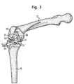
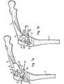
- Fig. 1 bis 7 u. 11
- verschiedene Phasen eines Teils einer Knieoperation, beidem mittels einer erfindungsgemäßen Vorrichtung eineFemurkondyle zum Einsetzen eines Femurimplantatsvorbereitet wird,
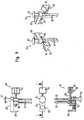
- Fig. 8
- verschiedene Ansichten einer kombinierten Schnitt- undBohrlehre gemäß einer Ausführungsform der Erfindung,
- Fig. 9
- verschiedene Ansichten einer separaten, mit derSchnitt- und Bohrlehre von Fig. 8 koppelbaren Kopp-lungseinrichtung gemäß einer Ausführungsform der Er-findung, und
- Fig. 10
- eine mit der Kopplungseinrichtung von Fig. 9 koppelba-re zusätzliche Schnittlehre gemäß einer Ausführungs-form der Erfindung.
- Fig. 1 to 7 u. 11
- different phases of a part of a knee operation in which a femoral condyle for inserting a femoral implant is prepared by means of a device according to the invention,
- Fig. 8
- various views of a combined cutting and drilling jig according to an embodiment of the invention,
- Fig. 9
- different views of a separate, coupled with the cutting and drilling of Figure 8 coupling device according to an embodiment of the invention, and
- Fig. 10
- 9 can be coupled to the coupling device of FIG. 9 additional cutting gauge according to an embodiment of the invention.
Bevor anhand der Fig. 8 bis 10 auf konstruktive Details der erfindungsgemäßenVorrichtung eingegangen wird, soll zunächst anhand der Fig. 1bis 7 und 11 derjenige Teil einer Knieoperation erläutert werden, bei demdie erfindungsgemäße Vorrichtung zum Einsatz kommt.Before with reference to FIGS. 8 to 10 to constructive details of the inventionDevice is received, first with reference to FIG. 17 to 11, that part of a knee operation will be explained in whichthe device according to the invention is used.
Bei der Operation, in der die erfindungsgemäße Vorrichtung gemäß demin den Figuren gezeigten Ausführungsbeispiel zum Einsatz kommt, handeltes sich um eine unikompartimentale Operation, bei der entweder imlateralen oder im medialen Kompartiment die Tibiakondyle und die Femurkondylezum Einsetzen eines Tibiaimplantats bzw. Femurimplantatsvorbereitet wird.In the operation in which the device according to the invention according to theused in the figures embodiment, is usedit is a unicompartmental operation in which either thelateral or medial compartment the tibial condyle and the femoral condylefor inserting a tibial implant or femoral implantis prepared.
Ausgangspunkt für denjenigen Teil der Operation, in dem die erfindungsgemäßeVorrichtung verwendet wird, ist hier ein durch zwei senkrecht zueinanderverlaufende Knochenschnitte hergestelltes Tibiaplateau, auf dasein gemäß der Operationsplanung vorgesehenes Tibiaimplantat aufgesetztwerden kann, sobald mit Hilfe der erfindungsgemäßen Vorrichtung auch die gegenüberliegende Femurkondyle zur Fixierung des entsprechendenFemurimplantats vorbereitet ist.Starting point for that part of the operation in which the inventiveDevice is used here is one by two perpendicular to each otherTibial plateau produced on the bonea scheduled according to the operation planning tibial implant placedcan be, as soon as with the help of the device according to the invention alsothe opposite femoral condyle to fix the correspondingFemoral Implant is prepared.
Das erfindungsgemäße Instrumentarium umfasst gemäß dem im Folgendenbeschriebenen Ausführungsbeispiel eine einstückig ausgebildete kombinierteSchnitt- und Bohrlehre 45, die einen Bohrlehrenabschnitt 41 undeinen Schnittlehrenabschnitt 37 umfasst.The instrumentation according to the invention comprises according to the followingdescribed embodiment, an integrally formed combinedCutting and
Im Anschluss an die Herstellung des Tibiaplateaus, die bei in Extensionbefindlichem Knie erfolgt, wird zunächst ebenfalls bei in Extension befindlichemKnie ein parallel zum Tibiaplateau verlaufender erster Kondylenschnitt39 ausgeführt. Dies erfolgt mittels einer Aufspreizeinrichtung 11,die auch in Verbindung mit der erfindungsgemäßen kombinierten Schnitt-und Bohrlehre 45 verwendet wird (vgl. Fig. 1). Anstelle der erfindungsgemäßenSchnitt- und Bohrlehre 45 ist zur Ausführung des ersten Kondylenschnittes39 bei in Extension befindlichem Knie ein anderer Funktionsaufsatzmit der Aufspreizeinrichtung 11 gekoppelt, der eine Schnittlehreumfasst, durch welche die Schnittebene für den ersten Kondylenschnitt39 definiert ist.Following the preparation of the tibial plateau, the at in extensionIf the knee is located, it is also initially in extensionKnee parallel to the tibial plateau extending
Mit der Aufspreizeinrichtung 11 wird das Knie aufgespreizt, d.h. der Abstandzwischen Tibia 14 und Femur 12 vergrößert, bis Femur 12 undTibia 14 in ihre natürliche Relativlage gebracht sind, die der Operateuranhand der natürlichen Spannung der Bänder ermitteln kann. Hierdurchist gewährleistet, dass der erste Femurkondylenschnitt 39 in der richtigenHöhe über dem Tibiaplateau ausgeführt wird.With the spreading device 11, the knee is spread open, i. the distanceenlarged between
Entsprechend ist bei in Flexion befindlichem Knie gemäß Fig. 1 und 2durch die Aufspreizeinrichtung 11 sichergestellt, dass Tibia 14 und Femur12 ihre korrekte Relativlage zueinander einnehmen und somit die lösbar mit einem höhenverstellbar an der Aufspreizeinrichtung 11 angebrachtenFunktionsaufsatz 13 koppelbare Schnitt- und Bohrlehre 45 bei korrekterRelativlage zwischen Femur 12 und Tibia 14 in einen an der Aufspreizeinrichtung11 ablesbaren Sollabstand vom Tibiaplateau gebracht werdenkann.Correspondingly, when the knee is in flexion according to FIGS. 1 and 2ensured by the Aufspreizeinrichtung 11 that
Die Aufspreizeinrichtung 11 umfasst ein Oberteil 19 mit einer plattenförmigenSpreizzunge 29 sowie ein Unterteil 17 mit einer ebenfalls plattenförmigenSpreizzunge 27. Mittels der beiden parallel zueinander verlaufendenSpreizzungen 27, 29 kann die Femurkondyle von dem Tibiaplateauweggedrückt werden, indem mittels eines als Stellschraube ausgebildetenBetätigungsorgans 21 das Oberteil 19 gegenüber dem Unterteil 17 angehobenwird.The spreading device 11 comprises an
Nachdem im Anschluss an das Aufspreizen des Knies die erfindungsgemäßeSchnitt- und Bohrlehre 45 durch Verstellen des Funktionsaufsatzes13 relativ zur Aufspreizeinrichtung 11 in die richtige Höhe über demTibiaplateau gebracht worden ist, wird der Funktionsaufsatz 13 mittelseiner Feststelleinrichtung 49 an der Aufspreizeinrichtung 11 festgesetzt.Daraufhin wird die verschiebbar auf einem Kopfabschnitt des Funktionsaufsatzes13 geführte Schnitt- und Bohrlehre 45 an die Femurkondyleherangeschoben.After following the spreading of the knee, the inventiveCutting and
Bevor die Schnitt- und Bohrlehre 45 an der Femurkondyle fixiert wird,wird sie mittels einer Ausrichthilfe 15 (vgl. Fig. 2) relativ zum Femur 12ausgerichtet. Hierzu kann die Lehre 45 mittels der Ausrichthilfe 15 umeine im Wesentlichen senkrecht zum Tibiaplateau verlaufende Achsezusammen mit der Aufspreizeinrichtung 11 verdreht werden. Außerdemist es möglich, die Lehre 45 zusammen mit der Aufspreizeinrichtung 11parallel zum Tibiaplateau zu verschieben.Before the cutting and
Das Ausrichten kann auch von Auge erfolgen, indem mit dem Bohrlehrenabschnitt41 ein 90°-Winkel zu einem in den Schlitz 39 eingesteckten Anschlagblech(z.B. zu dem in Fig. 7a und Fig. 11 gezeigten Blech 99, das inFig. 7a zu einem anderen Zweck verwendet wird) eingestellt wird. Eineweitere Ausrichtungsmöglichkeit gemäß Fig. 11 besteht darin, in dieKopplungsdurchgänge 73 des Bohrlehrenabschnitts 41 ein mit Stiften101 versehenes, in der während der Benutzung dem Knie zugewandtenEcke ausgespartes 90° Winkelblech 100 einzustecken, welches eine Kontrolledes Spaltes zum Anschlagblech 99 auf Parallelität relativ einfachmacht.The alignment can also be done by eye by using the drill guide section41 a 90 ° angle to an inserted into the
Die ein mehrteiliges Gestänge mit einer am Femur 12 ausrichtbarenJustierstange 16 umfassende Ausrichthilfe 15 ist seitlich in zwei im Bohrlehrenabschnitt41 der Lehre 45 ausgebildete, gemeinsam einen Kopplungsabschnitt23 der Lehre 45 bildende Kopplungsdurchgänge 73 steckbar.The a multi-part linkage with a femoral 12
Anschließend wird die korrekt ausgerichtete Lehre 45 mittels eines durcheinen Positionierdurchgang der Lehre 45 hindurchgeführten Positionierstiftes59 (vgl. Fig. 3) an der Femurkondyle positioniert, woraufhin über inder Lehre 45 ausgebildete Fixierdurchgänge in der Femurkondyle Bohrungenfür in Form von Knochenschrauben vorgesehene Fixierelemente 61,63 hergestellt werden, mittels welcher die Lehre 45 an der Femurkondylebefestigt wird.Subsequently, the correctly aligned
Dann wird die Aufspreizeinrichtung 11 abgenommen und mittels einesdurch einen im Schnittlehrenabschnitt 37 ausgebildeten Schlitz 57 hindurchgeführtenSchneidewerkzeugs in Form eines Sägeblatts 55 ein zweiterKondylenschnitt 43 (vgl. Fig. 4) ausgeführt, der im Wesentlichen parallel zum Tibiaplateau und damit im Wesentlichen senkrecht zum erstenKondylenschnitt 39 verläuft.Then the spreading device 11 is removed and by means of apassed through a formed in the
Als nächstes wird mit der nach wie vor an der Femurkondyle fixiertenLehre 45 über eine separate Kopplungseinrichtung 93 eine zusätzlicheSchnittlehre 81 gekoppelt (vgl. Fig. 4 und 5), die dazu dient, einen entsprechendder der Femurkondyle zugewandten gekrümmten Seite derLehre 45 verlaufenden weiteren Kondylenschnitt auszuführen.Next, with the still fixed to the
Hierzu wird die zusätzliche Schnittlehre 81 mittels einer Spannvorrichtung95 der Kopplungseinrichtung 93 an dieser eingespannt und anschließendüber die Kopplungseinrichtung 93 in einer definierten Lagerelativ zu der Lehre 45 mit dieser gekoppelt, indem Führungsstifte 97 derKopplungseinrichtung 93 von der Seite her in die bereits erwähnten, auchzur Koppelung mit der Ausrichthilfe 15 (vgl. Fig. 2) vorgesehenen Kopplungsdurchgänge73 gesteckt werden.For this purpose, the additional cutting
Die vorstehend erwähnte definierte Relativlage zeichnet sich dadurch aus,dass eine für ein Schneidewerkzeug vorgesehene Führungsfläche 87 derSchnittlehre 81 im über die Kopplungseinrichtung 93 mit der Lehre 45gekoppelten Zustand derart bezüglich der gekrümmten Seite der Lehre 45orientiert ist, dass die gekrümmte Seite der Lehre 45 und die Führungsfläche87 lediglich translatorisch gegeneinander versetzt sind. Folglichkann über die Führungsfläche 87 der Verlauf der gekrümmten Seite derLehre 45 auf die Femurkondyle übertragen werden, indem ein Schneidewerkzeugentlang der Führungsfläche 87 bewegt wird.The above-mentioned defined relative position is characterized bythat provided for a cutting
Bevor auf diese Weise der erwähnte weitere Kondylenschnitt ausgeführtwird, wird die zusätzliche Schnittlehre 81 ebenfalls an der Femurkondylefixiert. Fig. 5 zeigt, wie hierzu über in der Schnittlehre 81 ausgebildete, im an die Lehre 45 gekoppelten Zustand senkrecht zu den Fixierdurchgängender Lehre 45 verlaufende Fixierdurchgänge mittels eines Bohrers 25 dieFemurkondyle vorgebohrt wird. Die Fig. 6, 7a und 7b zeigen die zusätzlicheSchnittlehre 81 im mittels durch die Fixierdurchgänge hindurch in dieFemurkondyle gesteckter Fixierstifte 90 an der Femurkondyle fixiertenZustand.Before running in this way, the mentioned further Kondylenschnittis, the
Die richtige Lage der zusätzlichen Schnittlehre 81 relativ zur Femurkondyleist somit durch die ebenfalls korrekt positionierte und ausgerichteteSchnitt- und Bohrlehre 45 sichergestellt.The correct location of the additional cutting
Die Kopplungseinrichtung 93 wird anschließend abgenommen, wie es inFig. 6 angedeutet ist. Danach wird auch die kombinierte Schnitt- undBohrlehre 45 von der Femurkondyle abgenommen.The
Bevor mit Hilfe der Führungsfläche 87 der Schnittlehre 81 der weitereKondylenschnitt ausgeführt wird, wird gemäß Fig. 7a mit Hilfe eines ebenenAnschlagbleches 99 und eines Einstellwerkzeugs 82 die Führungsfläche87 relativ zur Femurkondyle verstellt, bis der Scheitelpunkt der konvexenFührungsfläche 87 in der durch den ersten Kondylenschnitt 39definierten Ebene liegt. Hierzu wird das Anschlagblech 99 in den erstenKondylenschnitt 39 eingeführt, wodurch die Schnittfläche des erstenKondylenschnittes 39 verlängert und so ein Anschlag für die Führungsfläche39 bereitgestellt wird.Before using the
Die Verstellbarkeit der Führungsfläche 87 ist dadurch gegeben, dass dieSchnittlehre 81 mehrteilig ausgebildet ist und eine Kurvenscheibe 85, ander die Führungsfläche 87 ausgebildet ist, sowie einen Basisabschnitt 91umfasst, der mit den Fixierdurchgängen für die Fixierstifte 90 versehenund über den die Schnittlehre 81 an der Femurkondyle fixiert ist.The adjustability of the
Das Einstellwerkzeug 82 dient zur Betätigung einer die Kurvenscheibe 85und den Basisabschnitt 91 miteinander verbindenden Stellschraube, derenmittels des Einstellwerkzeugs 82 bewirkte Drehbewegung eine Relativbewegungzwischen Kurvenscheibe 85 und Basisabschnitt 91 zur Folgehat, wodurch die Führungsfläche 87 vom Basisabschnitt 91 weg oder aufdiesen zu bewegt wird.The
Wenn der Scheitelpunkt der Führungsfläche 87 in der Ebene der erstenSchnittfläche 39 liegt, ist sichergestellt, dass das einzusetzende Femurimplantatsich in jeder Stellung des Kniegelenks im richtigen Abstand vondem einzusetzenden Tibiaimplantat befindet.If the vertex of the
Fig. 7b zeigt, wie mittels eines entlang der Führungsfläche 87 geführtenSchneidewerkzeugs in Form eines Sägeblatts 55 der gekrümmte weitereKondylenschnitt ausgeführt wird, wodurch zwischen den beiden zuvorhergestellten ebenen Kondylenschnittflächen 39, 43 eine gekrümmte Kondylenschnittfläche83 erzeugt wird, deren Verlauf der Krümmung der gekrümmtenSeite der Schnitt- und Bohrlehre 45 und damit der entsprechendenSeite des einzusetzenden Femurimplantats entspricht.FIG. 7b shows how, by means of a guided along the
In Fig. 7a und 7b sind die in der Femurkondyle in Verbindung mit derFixierung der kombinierten Schnitt- und Bohrlehre 45 ausgebildetenBohrungen 62, 64 zu erkennen, in die aufgrund der erfindungsgemäßenAusbildung des Bohrlehrenabschnitts 41 der Lehre 45 entsprechend demeinzusetzenden Femurimplantat dessen Zapfen gesteckt werden können.In Fig. 7a and 7b are in the femoral condyle in conjunction with theFixation of the combined cutting and drilling jig trained 45
Nachdem der gekrümmte Kondylenschnitt 83 ausgeführt worden ist, wirddie zusätzliche Schnittlehre 81 von der Femurkondyle abgenommen. Dasgemäß der Operationsplanung ausgewählte Femurimplantat kann dann - gegebenenfalls nach Vornahme weiterer Vorbereitungsschritte, aufdie hier nicht näher eingegangen werden soll - an der mittels der erfindungsgemäßenVorrichtung vorbereiteten Femurkondyle fixiert werden.After the
Gemäß Fig. 8 ist die in verschiedenen, einem Satz von vorhandenen Femurimplantatenentsprechenden Größen vorgesehene kombinierteSchnitt- und Bohrlehre 45 im unteren Bereich als mit einem Schlitz 57 fürein Sägeblatt versehene Schnittlehre 37 und im oberen Bereich als mitzwei Fixierdurchgängen 69 versehene Bohrlehre 41 ausgebildet, durch diejeweils ein Bohrer zum Vorbohren des Knochens und anschließend einFixierelement 61, 63 (vgl. Fig. 3), insbesondere eine Knochenschraube zurFixierung der Lehre 45 an der Femurkondyle, hindurchführbar sind.Referring now to Figure 8, there is a set of existing femoral implants in various setscorresponding sizes provided combinedCutting and
Wie vorstehend erwähnt, entspricht die Lehre 45 hinsichtlich der Krümmungihrer während der Operation der Femurkondyle zugewandten konkavenSeite 71 sowie hinsichtlich der Lage und der Orientierung der Fixierdurchgänge69 bezüglich der gekrümmten Seite 71 einem Femurimplantatgleicher Größe. Insofern wird bei der Operation mittels der Lehre45 das einzusetzende Femurimplantat simuliert.As mentioned above, the
An ihrem oberen Ende ist die Lehre 45 mit einem Positionierdurchgang 75versehen, durch den der Positionierstift 59 (vgl. z.B. Fig. 3) hindurchgeführtwird, um die Lehre 45 an der Femurkondyle zu halten, währendüber die Fixierdurchgänge 69 in der Femurkondyle die Bohrungen 62, 64für die Fixierschrauben 61, 63 bzw. für die Zapfen des einzusetzendenFemurimplantats ausgeführt werden.At its upper end is the
Des Weiteren ist die Lehre 45 in dem Bereich zwischen den beiden Fixierdurchgängen69 mit quer zu den Fixierdurchgängen 69 verlaufenden Kopplungsdurchgängen 73 versehen, die gemeinsam den Kopplungsabschnitt23 des Bohrlehrenabschnitts 41 bilden.Furthermore, the
Der Schnittlehrenabschnitt 37 der Lehre 45 ist gleichzeitig als Gleitsteckschuhausgebildet, mit dem die Lehre 45 auf den Funktionsaufsatz 13 derAufspreizeinrichtung 11 (vgl. Fig. 1) aufgesteckt und längs des Kopfabschnittsdes Funktionsaufsatzes 13 verschoben werden kann.The
Die in Fig. 9 dargestellte separate Kopplungseinrichtung 93 umfasst zweiparallel verlaufende Führungsstifte 97, die fest mit einem sich senkrechtzu den Führungsstiften 97 erstreckenden Ausleger 65 verbunden sind, deran seinem einen Ende einen parallel zu den Führungsstiften 97 vorstehendenAnschlagabschnitt 98 aufweist. Der Abstand der beiden Führungsstifte97 entspricht dem Abstand der in der erfindungsgemäßenSchnitt- und Bohrlehre 45 vgl. Fig. 8) ausgebildeten Kopplungsdurchgänge73.The
Zwischen dem Anschlagabschnitt 98 und dem freien Ende eines Klemmstempels96, der einen Griffabschnitt 94 aufweist und Bestandteil einerSpannvorrichtung 95 der Kopplungseinrichtung 93 ist, kann die nachstehendnäher in Verbindung mit Fig. 10 erläuterte zusätzliche Schnittlehre81 in einer definierten Lage relativ zur Kopplungseinrichtung 93 eingespanntwerden. Hierzu ist der Klemmstempel 96 als über den Griffabschnitt94 drehbare Klemmschraube ausgebildet, die über ein Gewindemit den Führungsstiften 97 zusammenwirkt.Between the
Zur Handhabung der Kopplungseinrichtung 93 beim Verbinden mit undbeim Lösen von der Schnitt- und Bohrlehre 45 kann der Operateur dieKopplungseinrichtung 93 mit der einen Hand an einem radial erweiterten Halteende 67 des einen Führungsstiftes 97 halten und mit der anderenHand die Spannvorrichtung 95 über den Griffabschnitt 94 betätigen.For handling the
Gemäß Fig. 10 umfasst die entsprechend der Schnitt- und Bohrlehre 45in verschiedenen, den vorhandenen Femurimplantatgrößen entsprechendenGrößen vorgesehene zusätzliche Schnittlehre 81 einen drei Fixierdurchgänge89 aufweisenden Basisabschnitt 91, relativ zu welchem einemit der konvexen Führungsfläche 87 versehene Kurvenscheibe 85 verstellbarist. Über in entsprechenden Durchgängen des Basisabschnitts 91verschiebbar gelagerte Zapfen 88 ist die Kurvenscheibe 85 am Basisabschnitt91 derart zwangsgeführt, dass lediglich eine geradlinige Relativbewegungzwischen Basisabschnitt 91 und Kurvenscheibe 85 möglich ist.According to FIG. 10, that corresponding to the cutting and
Das Verstellen der Kurvenscheibe 85 erfolgt mittels einer Stellschraube84, die über einen mit einem Außengewinde versehenen Schaft mit einemInnengewinde zusammenwirkt, das in einem weiteren Durchgang desBasisabschnitts 91 ausgebildet ist. Der ringförmige Kopf der Stellschraube84 ist zwischen der Rückseite der Kurvenscheibe 85 und einem als Federscheibeausgebildeten Federelement 86 an der Kurvenscheibe 85 spielfreiin Verstellrichtung gehalten. Die Federscheibe 86 stützt sich an einemringförmigen Abstützelement 92 ab, das fest mit der Kurvenscheibe 85verbunden ist.The adjustment of the
Mittels des in Fig. 7a dargestellten Einstellwerkzeugs wird die Stellschraube84 in den mit dem Innengewinde versehenen Durchgang des Basisabschnitts91 hinein oder aus diesem heraus geschraubt und auf diese Wiesedie Kurvenscheibe 85 in der durch die Zapfen 88 bzw. die die Zapfen 88aufnehmenden Durchgänge des Basisabschnitts 91 vorgegebenen Richtungrelativ zum Basisabschnitt 91 verstellt.By means of the adjustment tool shown in Fig. 7a is the
Wie bereits erwähnt, entspricht der Verlauf der konvexen Führungsfläche87 der Kurvenscheibe 85 der konkav gekrümmten Seite 71 der Schnitt-und Bohrlehre 45 (vgl. Fig. 8) und damit der entsprechenden Seite eineseinzusetzenden Femurimplantats gleicher Größe.As already mentioned, the course of the convex guide surface corresponds87 of the
Das freie Ende des Klemmstempels 96 der Kopplungseinrichtung 93 (vgl.Fig. 9) greift zum Einspannen der zusätzlichen Schnittlehre 81 an der inder Führungsfläche 87 ausgebildeten Öffnung an, über welche die Stellschraube84 zugänglich ist. Hierzu ist das freie Ende des Klemmstempels96 mit einer Abrundung versehen.The free end of the clamping
- 1111
- Aufspreizeinrichtungspreading device
- 1212
- Femurfemur
- 1313
- Funktionsaufsatzfunctional attachment
- 1414
- Tibiatibia
- 1515
- Ausrichthilfealignment
- 1616
- Justierstangeadjustment rod
- 1717
- Unterteillower part
- 1919
- Oberteiltop
- 2121
- Betätigungsorgan, StellschraubeActuator, set screw
- 2323
- Kopplungsabschnittcoupling portion
- 2525
- Bohrerdrill
- 2727
- Spreizzunge des UnterteilsSpreader tongue of the lower part
- 2929
- Spreizzunge des OberteilsSpreader tongue of the upper part
- 3737
- SchnittlehrenabschnittCutting guide section
- 3939
- erster Kondylenschnitt, erste Schnittflächefirst condyle incision, first cut surface
- 4141
- BohrlehrenabschnittBohrlehrenabschnitt
- 4343
- zweiter Kondylenschnitt, zweite Schnittflächesecond condyle section, second cut surface
- 4545
- kombinierte Schnitt- und Bohrlehrecombined cutting and drilling jig
- 4949
- FeststelleinrichtungLocking device
- 5555
- Schneidewerkzeug, SägeblattCutting tool, saw blade
- 5757
- Schlitzslot
- 5959
- Positionierstiftpositioning
- 6161
- Fixierelement, SchraubeFixing element, screw
- 6262
- Bohrungdrilling
- 6363
- Fixierelement, SchraubeFixing element, screw
- 6464
- Bohrungdrilling
- 6565
- Auslegerboom
- 6767
- Halteendeholding end
- 6969
- FixierdurchgangFixierdurchgang
- 7171
- gekrümmte Seitecurved side
- 7373
- KopplungsdurchgangCoupling passage
- 7575
- PositionierdurchgangPositionierdurchgang
- 8181
- zusätzliche Schnittlehreadditional cutting gauge
- 8282
- EinstellwerkzeugAdjusting
- 8383
- weiterer Kondylenschnitt, gekrümmte Schnittflächefurther condyle section, curved cut surface
- 8484
- Stellschraubescrew
- 8585
- Kurvenscheibecam
- 8686
- Federelement, FederscheibeSpring element, spring washer
- 8787
- Führungsflächeguide surface
- 8888
- Zapfenspigot
- 8989
- FixierdurchgangFixierdurchgang
- 9090
- Fixierstiftlocating pin
- 9191
- Basisabschnittbase section
- 9292
- Abstützelementsupporting
- 9393
- separate Kopplungseinrichtungseparate coupling device
- 9494
- Griffabschnitthandle portion
- 9595
- Spannvorrichtungjig
- 9696
- Klemmstempelterminal temple
- 9797
- Führungsstiftguide pin
- 9898
- Anschlagabschnittstop section
- 9999
- Anschlagblechstop plate
- 100100
- WinkelblechWinkelblech
- 101101
- Stiftpen
Claims (18)
- An apparatus for the preparation of a femoral condyle for the insertionof monocondylar knee implants,
comprising at least one combined cutting and drilling jig (45)which, when the knee is in flexion, can be fixed to the femoral condyleat a desired spacing from a tibia plateau dependent on thethickness of a tibia implant to be inserted,
the jig having a concave side (71) facing the femoral condyle andprovided with a curvature which has the course of the side of a femurimplant to be inserted facing the femoral condyle,
having at least one fixing passage (69) in a drilling section (41) of thejig for a drill and for a fixing element (61, 63), with the fixing passage(69) being positioned and oriented with respect to the curvedside (71) in accordance with the femur implant to be inserted andbeing suitable for the preparation of a bore for a spigot of the femurimplant to be inserted,
having at least one slot (57) in a cutting section (37) of the jig for acutting tool (55) by which a cutting plane for a condylar cut (43) isdefined, and
having a coupling section (23) for an alignment aid (15) by means ofwhich the cutting and drilling jig (45) located at the desired spacingfrom the tibia plateau is adjustable relative to the femoral condyle. - An apparatus in accordance with claim 1,characterized in that atleast one coupling passage (73) formed in the drilling section (41) ofthe jig and extending substantially perpendicular to the fixing passage (69) is provided as a coupling section (23) of the cutting anddrilling jig (45).
- An apparatus in accordance with claim 1 or claim 2,characterizedin that the cutting and drilling jig (45) can be coupled to a spreadingdevice (11) by means of which a desired spacing can be set betweenthe femoral condyle and an oppositely disposed tibia plateau.
- An apparatus in accordance with claim 3,characterized in that thecutting section (37) of the of the cutting and drilling jig (45) is simultaneouslymade as a slide attachment shoe which can be coupled tothe spreading device (11) and via which the cutting and drilling jig(45) is adjustable in a compulsorily guided manner at the spreadingdevice (11).
- An apparatus in accordance with any one of the preceding claimscharacterized in that the cutting and drilling jig (45) is provided, inaddition to the fixing passage (69), with a positioning passage (75)which is formed in the drilling section (41) of the jig and via whichthe cutting and drilling jig (45) is positionable relative to the femoralcondyle by means of a positioning pin (59) before the fixing to thefemoral condyle taking place via the fixing passage (69).
- An apparatus in accordance with any one of the preceding claimscharacterized in that the cutting and drilling jig (45) can be coupledto an additional cutting jig (81) with which, when the knee is in flexion,a further condylar cut (83) can be fixed which extends in acurved manner between two planar cut surfaces (39, 43) which have previously been established at the femoral condyle and of which theone cut surface (43) was formed by means of the cutting section (37)of the combined cutting and drilling jig (45) and the other cut surface(39) was made when the knee was in extension, with the twoplanar cut surfaces (39, 43) preferably extending at least substantiallyperpendicular to one another.
- An apparatus in accordance with claim 6,characterized in that thecourse of the curved side (71) of the combined cutting and drillingjig (45) is able to be mapped at least regionally on the femoralcondyle by means of the additional cutting jig (81)
- An apparatus in accordance with claim 6 or claim 7,characterizedin that the additional cutting jig (81) includes a disk cam (85) with aconvex guide surface (87) along which a cutting tool (55) is guidableand whose extent corresponds to the curved side (71) of the combinedcutting and drilling jig (45).
- An apparatus in accordance with claim 8,characterized in that theadditional cutting jig (81) is oriented with respect to the cutting anddrilling jig (45) in the state coupled to the cutting and drilling jig (45)fixed to the femoral condyle such that the guide surface (87) of theadditional cutting jig (81) and the curved side (71) of the cutting anddrilling jig (45) are only translatorily offset toward one another.
- An apparatus in accordance with one of claims 6 to 9,characterizedin that the additional cutting jig (81) is likewise fixable to the femoral condyle in the state coupled to the cutting and drilling jig (45)fixed to the femoral condyle.
- An apparatus in accordance with one of claims 6 to 10,characterizedin that the additional cutting jig (81) is provided with at leastone fixing passage (89), and preferably a plurality of fixing passages,which extend substantially perpendicular to the fixing passage (69)of the combined cutting and drilling jig (45) in the state coupled tothe combined cutting and drilling jig (45).
- An apparatus in accordance with one of claims 8 to 11,characterizedin that the guide surface (87) is adjustable relative to the femoralcondyle with the additional cutting jig (81) fixed to the femoralcondyle.
- An apparatus in accordance with one of claims 8 to 12,characterizedin that the additional cutting jig (81) includes a base section(91) which can be fixed to the femoral condyle and to which the diskcam (85) is adjustably attached with the base section (91) fixed tothe femoral condyle for the alignment of the guide surface (87)formed at the cam disk (85) with a condylar cut (39) which was previouslycarried out, when the knee was in extension, at a desiredspacing from the tibia plateau dependent on the thickness of a tibiaimplant to be inserted.
- An apparatus in accordance with claim 13,characterized in that thedisk cam (85) is adjustable relative to the base section (91) fixed tothe femoral condyle such that the vertex of the guide surface (87) formed at the disk cam (85) is disposed in the plane defined by thecondylar cut (39).
- An apparatus in accordance with one of claims 6 to 14,characterizedin that the coupling section (23) of the combined cutting anddrilling jig (45) provided for the alignment aid (15) is simultaneouslymade for coupling to the additional cutting jig (81).
- An apparatus in accordance with one of claims 6 to 15,characterizedin that a separate coupling device (93) is provided for the couplingof the additional cutting jig (81) to the combined cutting anddrilling jig (45) at which the additional cutting jig (81) can be fixedand with which the additional cutting jig (81) is adjustable, in particularlinearly displaceable, relative to the combined cutting anddrilling jig (45) in the fixed state.
- An apparatus in accordance with claim 16,characterized in that thecoupling device (93) includes a clamping device (95) by means ofwhich the additional cutting jig (81) is fixingly clampable to the couplingdevice (93).
- An apparatus in accordance with claim 16 or claim 17,characterizedin that the coupling device (93) is removable with the combinedcutting and drilling jig (45) and the additional cutting jig (81) fixed tothe femoral condyle.
Priority Applications (6)
| Application Number | Priority Date | Filing Date | Title |
|---|---|---|---|
| AT03009438TATE305752T1 (en) | 2003-04-25 | 2003-04-25 | DEVICE FOR PREPARING A FEMURAL CONDYLE |
| ES03009438TES2246438T3 (en) | 2003-04-25 | 2003-04-25 | DEVICE FOR THE PREPARATION OF A FEMORAL CONDILO. |
| DE50301302TDE50301302D1 (en) | 2003-04-25 | 2003-04-25 | Device for preparing a femoral condyle |
| EP03009438AEP1470786B1 (en) | 2003-04-25 | 2003-04-25 | Device for preparation of a femoral condyle |
| US10/822,122US7201755B2 (en) | 2003-04-25 | 2004-04-09 | Apparatus for the preparation of a femoral condyle |
| AU2004201721AAU2004201721B2 (en) | 2003-04-25 | 2004-04-23 | An apparatus for the preparation of a femoral condyle |
Applications Claiming Priority (1)
| Application Number | Priority Date | Filing Date | Title |
|---|---|---|---|
| EP03009438AEP1470786B1 (en) | 2003-04-25 | 2003-04-25 | Device for preparation of a femoral condyle |
Publications (2)
| Publication Number | Publication Date |
|---|---|
| EP1470786A1 EP1470786A1 (en) | 2004-10-27 |
| EP1470786B1true EP1470786B1 (en) | 2005-10-05 |
Family
ID=32946883
Family Applications (1)
| Application Number | Title | Priority Date | Filing Date |
|---|---|---|---|
| EP03009438AExpired - LifetimeEP1470786B1 (en) | 2003-04-25 | 2003-04-25 | Device for preparation of a femoral condyle |
Country Status (6)
| Country | Link |
|---|---|
| US (1) | US7201755B2 (en) |
| EP (1) | EP1470786B1 (en) |
| AT (1) | ATE305752T1 (en) |
| AU (1) | AU2004201721B2 (en) |
| DE (1) | DE50301302D1 (en) |
| ES (1) | ES2246438T3 (en) |
Families Citing this family (68)
| Publication number | Priority date | Publication date | Assignee | Title |
|---|---|---|---|---|
| US7618451B2 (en) | 2001-05-25 | 2009-11-17 | Conformis, Inc. | Patient selectable joint arthroplasty devices and surgical tools facilitating increased accuracy, speed and simplicity in performing total and partial joint arthroplasty |
| US20030055502A1 (en) | 2001-05-25 | 2003-03-20 | Philipp Lang | Methods and compositions for articular resurfacing |
| US8083745B2 (en) | 2001-05-25 | 2011-12-27 | Conformis, Inc. | Surgical tools for arthroplasty |
| US7534263B2 (en) | 2001-05-25 | 2009-05-19 | Conformis, Inc. | Surgical tools facilitating increased accuracy, speed and simplicity in performing joint arthroplasty |
| US7468075B2 (en) | 2001-05-25 | 2008-12-23 | Conformis, Inc. | Methods and compositions for articular repair |
| WO2000035346A2 (en) | 1998-09-14 | 2000-06-22 | Stanford University | Assessing the condition of a joint and preventing damage |
| US7239908B1 (en) | 1998-09-14 | 2007-07-03 | The Board Of Trustees Of The Leland Stanford Junior University | Assessing the condition of a joint and devising treatment |
| US9289153B2 (en)* | 1998-09-14 | 2016-03-22 | The Board Of Trustees Of The Leland Stanford Junior University | Joint and cartilage diagnosis, assessment and modeling |
| DE60136474D1 (en) | 2000-09-14 | 2008-12-18 | Univ R | ASSESSMENT OF THE CONDITION OF A JOINT AND LOSS OF CARTEL TISSUE |
| ATE426357T1 (en) | 2000-09-14 | 2009-04-15 | Univ Leland Stanford Junior | ASSESSING THE CONDITION OF A JOINT AND PLANNING TREATMENT |
| US8439926B2 (en) | 2001-05-25 | 2013-05-14 | Conformis, Inc. | Patient selectable joint arthroplasty devices and surgical tools |
| US7094241B2 (en) | 2002-11-27 | 2006-08-22 | Zimmer Technology, Inc. | Method and apparatus for achieving correct limb alignment in unicondylar knee arthroplasty |
| DE50303568D1 (en)* | 2003-04-25 | 2006-07-06 | Zimmer Gmbh | Device for preparing a femoral condyle |
| JP4231813B2 (en)* | 2003-05-06 | 2009-03-04 | ツィマー ゲーエムベーハー | Traction equipment |
| ATE289787T1 (en) | 2003-09-15 | 2005-03-15 | Zimmer Gmbh | ADJUSTMENT DEVICE |
| US7641661B2 (en)* | 2003-12-26 | 2010-01-05 | Zimmer Technology, Inc. | Adjustable resection guide |
| GB0405386D0 (en)* | 2004-03-10 | 2004-04-21 | Depuy Int Ltd | Device |
| US8167888B2 (en)* | 2004-08-06 | 2012-05-01 | Zimmer Technology, Inc. | Tibial spacer blocks and femoral cutting guide |
| US20060155294A1 (en)* | 2005-01-11 | 2006-07-13 | Zimmer Technology, Inc. | Tibial/femoral recutter with paddle |
| US7601154B2 (en)* | 2005-04-18 | 2009-10-13 | Uni-Knee, Llc | Unicondylar knee instrument system |
| US20080132895A1 (en)* | 2005-08-05 | 2008-06-05 | Ron Clark | Instruments and method for arthroscopic arthroplasty of the knee |
| US7780671B2 (en)* | 2006-01-23 | 2010-08-24 | Zimmer Technology, Inc. | Bone resection apparatus and method for knee surgery |
| US8623026B2 (en) | 2006-02-06 | 2014-01-07 | Conformis, Inc. | Patient selectable joint arthroplasty devices and surgical tools incorporating anatomical relief |
| CN105030296A (en) | 2006-02-06 | 2015-11-11 | 康复米斯公司 | Patient selectable joint arthroplasty devices and surgical tools |
| US8568487B2 (en) | 2006-02-27 | 2013-10-29 | Biomet Manufacturing, Llc | Patient-specific hip joint devices |
| US8603180B2 (en) | 2006-02-27 | 2013-12-10 | Biomet Manufacturing, Llc | Patient-specific acetabular alignment guides |
| US7967868B2 (en) | 2007-04-17 | 2011-06-28 | Biomet Manufacturing Corp. | Patient-modified implant and associated method |
| US9113971B2 (en) | 2006-02-27 | 2015-08-25 | Biomet Manufacturing, Llc | Femoral acetabular impingement guide |
| US9289253B2 (en) | 2006-02-27 | 2016-03-22 | Biomet Manufacturing, Llc | Patient-specific shoulder guide |
| US8407067B2 (en) | 2007-04-17 | 2013-03-26 | Biomet Manufacturing Corp. | Method and apparatus for manufacturing an implant |
| US9918740B2 (en) | 2006-02-27 | 2018-03-20 | Biomet Manufacturing, Llc | Backup surgical instrument system and method |
| US9907659B2 (en) | 2007-04-17 | 2018-03-06 | Biomet Manufacturing, Llc | Method and apparatus for manufacturing an implant |
| US8591516B2 (en) | 2006-02-27 | 2013-11-26 | Biomet Manufacturing, Llc | Patient-specific orthopedic instruments |
| US9173661B2 (en) | 2006-02-27 | 2015-11-03 | Biomet Manufacturing, Llc | Patient specific alignment guide with cutting surface and laser indicator |
| US8092465B2 (en)* | 2006-06-09 | 2012-01-10 | Biomet Manufacturing Corp. | Patient specific knee alignment guide and associated method |
| US9339278B2 (en) | 2006-02-27 | 2016-05-17 | Biomet Manufacturing, Llc | Patient-specific acetabular guides and associated instruments |
| US20150335438A1 (en) | 2006-02-27 | 2015-11-26 | Biomet Manufacturing, Llc. | Patient-specific augments |
| US9345548B2 (en) | 2006-02-27 | 2016-05-24 | Biomet Manufacturing, Llc | Patient-specific pre-operative planning |
| US10278711B2 (en) | 2006-02-27 | 2019-05-07 | Biomet Manufacturing, Llc | Patient-specific femoral guide |
| US9795399B2 (en) | 2006-06-09 | 2017-10-24 | Biomet Manufacturing, Llc | Patient-specific knee alignment guide and associated method |
| US7678115B2 (en)* | 2006-06-21 | 2010-03-16 | Howmedia Osteonics Corp. | Unicondylar knee implants and insertion methods therefor |
| US20080140081A1 (en)* | 2006-12-04 | 2008-06-12 | Zimmer, Inc. | Cut guides |
| US20080172054A1 (en)* | 2007-01-16 | 2008-07-17 | Zimmer Technology, Inc. | Orthopedic device for securing to tissue |
| US20080183176A1 (en)* | 2007-01-26 | 2008-07-31 | Howmedica Osteonics Corp. | Linked tibial resection guide |
| US20080255573A1 (en)* | 2007-04-10 | 2008-10-16 | Zimmer, Inc. | Surgical laser trajectory instrument |
| WO2008157412A2 (en) | 2007-06-13 | 2008-12-24 | Conformis, Inc. | Surgical cutting guide |
| US20090299375A1 (en)* | 2008-06-03 | 2009-12-03 | Zimmer, Inc. | Catheter nail targeting guide |
| US12383287B2 (en) | 2009-02-24 | 2025-08-12 | Microport Orthopedics Holdings, Inc. | Systems and methods for installing an orthopedic implant |
| US9017334B2 (en) | 2009-02-24 | 2015-04-28 | Microport Orthopedics Holdings Inc. | Patient specific surgical guide locator and mount |
| US8808303B2 (en) | 2009-02-24 | 2014-08-19 | Microport Orthopedics Holdings Inc. | Orthopedic surgical guide |
| US8808297B2 (en) | 2009-02-24 | 2014-08-19 | Microport Orthopedics Holdings Inc. | Orthopedic surgical guide |
| SG10201401326SA (en) | 2009-04-16 | 2014-10-30 | Conformis Inc | Patient-specific joint arthroplasty devices for ligament repair |
| GB2475491A (en)* | 2009-11-18 | 2011-05-25 | Biomet Uk Ltd | Alignment tool for a femoral drill guide |
| GB2479899A (en)* | 2010-04-28 | 2011-11-02 | Biomet Uk Ltd | Alignment tool for use in joint replacement |
| US9968376B2 (en) | 2010-11-29 | 2018-05-15 | Biomet Manufacturing, Llc | Patient-specific orthopedic instruments |
| US8672946B2 (en) | 2011-02-11 | 2014-03-18 | Biomet Manfacturing, LLC | Method and apparatus for performing knee arthroplasty |
| US9241745B2 (en) | 2011-03-07 | 2016-01-26 | Biomet Manufacturing, Llc | Patient-specific femoral version guide |
| EP2561814A1 (en)* | 2011-08-25 | 2013-02-27 | Deru GmbH | Cutting guide for creating an external contour for an articulated endoprosthetic |
| US9486226B2 (en) | 2012-04-18 | 2016-11-08 | Conformis, Inc. | Tibial guides, tools, and techniques for resecting the tibial plateau |
| US9675471B2 (en) | 2012-06-11 | 2017-06-13 | Conformis, Inc. | Devices, techniques and methods for assessing joint spacing, balancing soft tissues and obtaining desired kinematics for joint implant components |
| FR3022764A1 (en)* | 2014-06-25 | 2016-01-01 | Orthonova | GUIDE FOR BEING POSITIONED ON A BONE OF A JOINT TO BE OPERATED, METHOD OF MANUFACTURING THE SAME AND METHODS OF SURGICAL OPERATION USING THE SAME |
| US11266420B2 (en)* | 2014-08-06 | 2022-03-08 | Unik Orthopedics, Inc. | Sparse contact femoral jig mechanism |
| US11540928B2 (en)* | 2017-03-03 | 2023-01-03 | Engage Uni Llc | Unicompartmental knee arthroplasty |
| US10722310B2 (en) | 2017-03-13 | 2020-07-28 | Zimmer Biomet CMF and Thoracic, LLC | Virtual surgery planning system and method |
| EP3975939B1 (en) | 2019-05-29 | 2024-11-13 | Wright Medical Technology, Inc. | Device for preparing a tibia for receiving tibial implant component of a replacement ankle |
| WO2021146015A1 (en) | 2020-01-17 | 2021-07-22 | Wright Medical Technology, Inc. | Guidance tools, systems, and methods |
| US11701130B2 (en) | 2021-06-11 | 2023-07-18 | Optimotion Implants LLC | Arthroplasty balance and gap gauge and cutting guidance |
| US11751884B2 (en) | 2021-06-11 | 2023-09-12 | Optimotion Implants LLC | Arthroplasty balance and gap gauge and cutting guidance |
Family Cites Families (16)
| Publication number | Priority date | Publication date | Assignee | Title |
|---|---|---|---|---|
| US4349018A (en) | 1980-12-29 | 1982-09-14 | Chambers Gary R | Osteotomy apparatus |
| US4759350A (en) | 1986-10-17 | 1988-07-26 | Dunn Harold K | Instruments for shaping distal femoral and proximal tibial surfaces |
| FR2679766B1 (en) | 1991-07-30 | 1998-08-28 | Sophia Med | DEVICE FOR LAYING A KNEE PROSTHESIS. |
| US5681320A (en)* | 1991-12-13 | 1997-10-28 | Mcguire; David A. | Bone-cutting guide |
| US5275603A (en) | 1992-02-20 | 1994-01-04 | Wright Medical Technology, Inc. | Rotationally and angularly adjustable tibial cutting guide and method of use |
| US5364402A (en) | 1993-07-29 | 1994-11-15 | Intermedics Orthopedics, Inc. | Tibial spacer saw guide |
| US5643272A (en)* | 1994-09-02 | 1997-07-01 | Hudson Surgical Design, Inc. | Method and apparatus for tibial resection |
| US6695848B2 (en)* | 1994-09-02 | 2004-02-24 | Hudson Surgical Design, Inc. | Methods for femoral and tibial resection |
| FR2726178B1 (en)* | 1994-10-27 | 1997-03-28 | Impact | FEMALE ANCILLARY INSTRUMENTATION FOR THE IMPLANTATION OF A UNICOMPARTMENTAL KNEE PROSTHESIS |
| GB9611074D0 (en) | 1996-05-28 | 1996-07-31 | Howmedica | Surgical apparatus |
| AU737097B2 (en)* | 1997-01-28 | 2001-08-09 | New York Society For The Relief Of The Ruptured And Crippled, Maintaining The Hospital For Special Surgery | Method and apparatus for femoral resection |
| ES2553715T3 (en)* | 2000-03-10 | 2015-12-11 | Smith & Nephew, Inc. | Apparatus for use in arthroplasty in a knee joint |
| AU2001250538A1 (en)* | 2000-04-27 | 2001-11-20 | Finsbury (Development) Limited | Surgical tool |
| US7141053B2 (en)* | 2001-11-28 | 2006-11-28 | Wright Medical Technology, Inc. | Methods of minimally invasive unicompartmental knee replacement |
| DE20303498U1 (en) | 2003-02-26 | 2003-07-03 | Aesculap AG & Co. KG, 78532 Tuttlingen | Surgical adjusting and holding device for tool guiding arrangement, in particular for performance of operation at femur or tibia |
| DE50303568D1 (en)* | 2003-04-25 | 2006-07-06 | Zimmer Gmbh | Device for preparing a femoral condyle |
- 2003
- 2003-04-25EPEP03009438Apatent/EP1470786B1/ennot_activeExpired - Lifetime
- 2003-04-25ATAT03009438Tpatent/ATE305752T1/ennot_activeIP Right Cessation
- 2003-04-25DEDE50301302Tpatent/DE50301302D1/ennot_activeExpired - Lifetime
- 2003-04-25ESES03009438Tpatent/ES2246438T3/ennot_activeExpired - Lifetime
- 2004
- 2004-04-09USUS10/822,122patent/US7201755B2/ennot_activeExpired - Lifetime
- 2004-04-23AUAU2004201721Apatent/AU2004201721B2/ennot_activeCeased
Also Published As
| Publication number | Publication date |
|---|---|
| US7201755B2 (en) | 2007-04-10 |
| AU2004201721A1 (en) | 2004-11-11 |
| US20040249386A1 (en) | 2004-12-09 |
| DE50301302D1 (en) | 2005-11-10 |
| EP1470786A1 (en) | 2004-10-27 |
| ATE305752T1 (en) | 2005-10-15 |
| AU2004201721B2 (en) | 2007-05-17 |
| ES2246438T3 (en) | 2006-02-16 |
Similar Documents
| Publication | Publication Date | Title |
|---|---|---|
| EP1470786B1 (en) | Device for preparation of a femoral condyle | |
| EP1470787B1 (en) | Device for preparation of a femoral condyle | |
| EP1709914B1 (en) | Ligament tensioning device with cutting jig | |
| EP1470788B1 (en) | Bone cutting guide | |
| DE60216667T2 (en) | Device for positioning the cutting plane of a bone saw guide | |
| DE60214290T2 (en) | Auxiliary device for positioning a humeral part of an elbow prosthesis | |
| DE69324233T2 (en) | EXTERNAL ALIGNMENT SYSTEM | |
| DE69621532T2 (en) | Device for correcting the distances between bone resection planes for knee prostheses | |
| DE69630776T2 (en) | TIBIAL RESECTION INSTRUMENT | |
| DE69519169T2 (en) | MECHANICAL DEVICE FOR ALIGNING BONE SCREWS TO BE INSERTED IN A MARKEL | |
| EP0322363A1 (en) | Positioning device for total condylar knee prostheses | |
| EP1561431A1 (en) | Device for determining the position of a cutting guide | |
| DE9301611U1 (en) | Orthopaedic instrument | |
| DE102012201970B4 (en) | Method and device for performing an arthroplasty | |
| DE102010013258A1 (en) | Device for positioning of cutting guide elements at femur bone in the knee endoprosthetics, has fixing element which is connected with cutting guide element and comprises anchor and coupling element | |
| EP2515771A1 (en) | Femoral cutting guide device for revision operations in knee endoprosthetics | |
| DE2442927A1 (en) | KNEE JOINT ENDOPROTHESIS | |
| DE10358926B4 (en) | Resektionsschnittlehre | |
| DE60206772T2 (en) | GUIDANCE ON THE LOCALIZATION OF THE RESEARCH SURFACES OF THE FEMUR | |
| EP3429484B1 (en) | Surgical device for surgery of the human knee | |
| EP2205165B1 (en) | Saw gauge for performing a bone resection | |
| EP1367946B1 (en) | System for reconstructing the natural torsion between the natural knee and the natural hip area | |
| EP3095398B1 (en) | Patient-specific instrument for the referencing of body parts | |
| EP2081505B1 (en) | Jig for performing a transposition osteotomy | |
| DE102023104682A1 (en) | A DEVICE AND METHOD FOR ALIGNING SURGICAL TOOLS |
Legal Events
| Date | Code | Title | Description |
|---|---|---|---|
| PUAI | Public reference made under article 153(3) epc to a published international application that has entered the european phase | Free format text:ORIGINAL CODE: 0009012 | |
| 17P | Request for examination filed | Effective date:20040225 | |
| AK | Designated contracting states | Kind code of ref document:A1 Designated state(s):AT BE BG CH CY CZ DE DK EE ES FI FR GB GR HU IE IT LI LU MC NL PT RO SE SI SK TR | |
| AX | Request for extension of the european patent | Extension state:AL LT LV MK | |
| RIN1 | Information on inventor provided before grant (corrected) | Inventor name:OVERES, TOM Inventor name:FAORO, FRANCISCO | |
| GRAP | Despatch of communication of intention to grant a patent | Free format text:ORIGINAL CODE: EPIDOSNIGR1 | |
| RAP1 | Party data changed (applicant data changed or rights of an application transferred) | Owner name:ZIMMER GMBH | |
| AKX | Designation fees paid | Designated state(s):AT BE BG CH CY CZ DE DK EE ES FI FR GB GR HU IE IT LI LU MC NL PT RO SE SI SK TR | |
| GRAS | Grant fee paid | Free format text:ORIGINAL CODE: EPIDOSNIGR3 | |
| GRAA | (expected) grant | Free format text:ORIGINAL CODE: 0009210 | |
| AK | Designated contracting states | Kind code of ref document:B1 Designated state(s):AT BE BG CH CY CZ DE DK EE ES FI FR GB GR HU IE IT LI LU MC NL PT RO SE SI SK TR | |
| PG25 | Lapsed in a contracting state [announced via postgrant information from national office to epo] | Ref country code:SK Free format text:LAPSE BECAUSE OF FAILURE TO SUBMIT A TRANSLATION OF THE DESCRIPTION OR TO PAY THE FEE WITHIN THE PRESCRIBED TIME-LIMIT Effective date:20051005 Ref country code:RO Free format text:LAPSE BECAUSE OF FAILURE TO SUBMIT A TRANSLATION OF THE DESCRIPTION OR TO PAY THE FEE WITHIN THE PRESCRIBED TIME-LIMIT Effective date:20051005 Ref country code:CZ Free format text:LAPSE BECAUSE OF FAILURE TO SUBMIT A TRANSLATION OF THE DESCRIPTION OR TO PAY THE FEE WITHIN THE PRESCRIBED TIME-LIMIT Effective date:20051005 Ref country code:SI Free format text:LAPSE BECAUSE OF FAILURE TO SUBMIT A TRANSLATION OF THE DESCRIPTION OR TO PAY THE FEE WITHIN THE PRESCRIBED TIME-LIMIT Effective date:20051005 Ref country code:FI Free format text:LAPSE BECAUSE OF FAILURE TO SUBMIT A TRANSLATION OF THE DESCRIPTION OR TO PAY THE FEE WITHIN THE PRESCRIBED TIME-LIMIT Effective date:20051005 Ref country code:NL Free format text:LAPSE BECAUSE OF FAILURE TO SUBMIT A TRANSLATION OF THE DESCRIPTION OR TO PAY THE FEE WITHIN THE PRESCRIBED TIME-LIMIT Effective date:20051005 Ref country code:IE Free format text:LAPSE BECAUSE OF FAILURE TO SUBMIT A TRANSLATION OF THE DESCRIPTION OR TO PAY THE FEE WITHIN THE PRESCRIBED TIME-LIMIT Effective date:20051005 | |
| REG | Reference to a national code | Ref country code:GB Ref legal event code:FG4D Free format text:NOT ENGLISH | |
| REG | Reference to a national code | Ref country code:CH Ref legal event code:EP Ref country code:CH Ref legal event code:NV Representative=s name:DR. GRAF & PARTNER INTELLECTUAL PROPERTY | |
| REG | Reference to a national code | Ref country code:IE Ref legal event code:FG4D Free format text:LANGUAGE OF EP DOCUMENT: GERMAN | |
| REF | Corresponds to: | Ref document number:50301302 Country of ref document:DE Date of ref document:20051110 Kind code of ref document:P | |
| GBT | Gb: translation of ep patent filed (gb section 77(6)(a)/1977) | Effective date:20051128 | |
| PG25 | Lapsed in a contracting state [announced via postgrant information from national office to epo] | Ref country code:DK Free format text:LAPSE BECAUSE OF FAILURE TO SUBMIT A TRANSLATION OF THE DESCRIPTION OR TO PAY THE FEE WITHIN THE PRESCRIBED TIME-LIMIT Effective date:20060105 Ref country code:SE Free format text:LAPSE BECAUSE OF FAILURE TO SUBMIT A TRANSLATION OF THE DESCRIPTION OR TO PAY THE FEE WITHIN THE PRESCRIBED TIME-LIMIT Effective date:20060105 Ref country code:GR Free format text:LAPSE BECAUSE OF FAILURE TO SUBMIT A TRANSLATION OF THE DESCRIPTION OR TO PAY THE FEE WITHIN THE PRESCRIBED TIME-LIMIT Effective date:20060105 Ref country code:BG Free format text:LAPSE BECAUSE OF FAILURE TO SUBMIT A TRANSLATION OF THE DESCRIPTION OR TO PAY THE FEE WITHIN THE PRESCRIBED TIME-LIMIT Effective date:20060105 | |
| REG | Reference to a national code | Ref country code:ES Ref legal event code:FG2A Ref document number:2246438 Country of ref document:ES Kind code of ref document:T3 | |
| NLV1 | Nl: lapsed or annulled due to failure to fulfill the requirements of art. 29p and 29m of the patents act | ||
| PG25 | Lapsed in a contracting state [announced via postgrant information from national office to epo] | Ref country code:PT Free format text:LAPSE BECAUSE OF FAILURE TO SUBMIT A TRANSLATION OF THE DESCRIPTION OR TO PAY THE FEE WITHIN THE PRESCRIBED TIME-LIMIT Effective date:20060306 | |
| PG25 | Lapsed in a contracting state [announced via postgrant information from national office to epo] | Ref country code:HU Free format text:LAPSE BECAUSE OF FAILURE TO SUBMIT A TRANSLATION OF THE DESCRIPTION OR TO PAY THE FEE WITHIN THE PRESCRIBED TIME-LIMIT Effective date:20060406 | |
| PG25 | Lapsed in a contracting state [announced via postgrant information from national office to epo] | Ref country code:MC Free format text:LAPSE BECAUSE OF NON-PAYMENT OF DUE FEES Effective date:20060430 Ref country code:BE Free format text:LAPSE BECAUSE OF NON-PAYMENT OF DUE FEES Effective date:20060430 | |
| REG | Reference to a national code | Ref country code:IE Ref legal event code:FD4D | |
| ET | Fr: translation filed | ||
| PLBE | No opposition filed within time limit | Free format text:ORIGINAL CODE: 0009261 | |
| STAA | Information on the status of an ep patent application or granted ep patent | Free format text:STATUS: NO OPPOSITION FILED WITHIN TIME LIMIT | |
| 26N | No opposition filed | Effective date:20060706 | |
| BERE | Be: lapsed | Owner name:ZIMMER GMBH Effective date:20060430 | |
| PG25 | Lapsed in a contracting state [announced via postgrant information from national office to epo] | Ref country code:EE Free format text:LAPSE BECAUSE OF FAILURE TO SUBMIT A TRANSLATION OF THE DESCRIPTION OR TO PAY THE FEE WITHIN THE PRESCRIBED TIME-LIMIT Effective date:20051005 | |
| PG25 | Lapsed in a contracting state [announced via postgrant information from national office to epo] | Ref country code:TR Free format text:LAPSE BECAUSE OF FAILURE TO SUBMIT A TRANSLATION OF THE DESCRIPTION OR TO PAY THE FEE WITHIN THE PRESCRIBED TIME-LIMIT Effective date:20051005 Ref country code:LU Free format text:LAPSE BECAUSE OF NON-PAYMENT OF DUE FEES Effective date:20060425 | |
| PGFP | Annual fee paid to national office [announced via postgrant information from national office to epo] | Ref country code:ES Payment date:20080429 Year of fee payment:6 | |
| PGFP | Annual fee paid to national office [announced via postgrant information from national office to epo] | Ref country code:AT Payment date:20080415 Year of fee payment:6 | |
| PG25 | Lapsed in a contracting state [announced via postgrant information from national office to epo] | Ref country code:CY Free format text:LAPSE BECAUSE OF FAILURE TO SUBMIT A TRANSLATION OF THE DESCRIPTION OR TO PAY THE FEE WITHIN THE PRESCRIBED TIME-LIMIT Effective date:20051005 | |
| PG25 | Lapsed in a contracting state [announced via postgrant information from national office to epo] | Ref country code:AT Free format text:LAPSE BECAUSE OF NON-PAYMENT OF DUE FEES Effective date:20090425 | |
| REG | Reference to a national code | Ref country code:CH Ref legal event code:PFA Owner name:ZIMMER GMBH Free format text:ZIMMER GMBH#SULZER ALLEE 8#8404 WINTERTHUR (CH) -TRANSFER TO- ZIMMER GMBH#SULZER ALLEE 8#8404 WINTERTHUR (CH) | |
| REG | Reference to a national code | Ref country code:ES Ref legal event code:FD2A Effective date:20090427 | |
| PG25 | Lapsed in a contracting state [announced via postgrant information from national office to epo] | Ref country code:ES Free format text:LAPSE BECAUSE OF NON-PAYMENT OF DUE FEES Effective date:20090427 | |
| REG | Reference to a national code | Ref country code:FR Ref legal event code:PLFP Year of fee payment:14 | |
| REG | Reference to a national code | Ref country code:FR Ref legal event code:PLFP Year of fee payment:15 | |
| REG | Reference to a national code | Ref country code:FR Ref legal event code:PLFP Year of fee payment:16 | |
| PGFP | Annual fee paid to national office [announced via postgrant information from national office to epo] | Ref country code:NL Payment date:20190121 Year of fee payment:15 | |
| PGFP | Annual fee paid to national office [announced via postgrant information from national office to epo] | Ref country code:GB Payment date:20200316 Year of fee payment:18 | |
| PGFP | Annual fee paid to national office [announced via postgrant information from national office to epo] | Ref country code:CH Payment date:20200313 Year of fee payment:18 | |
| PGFP | Annual fee paid to national office [announced via postgrant information from national office to epo] | Ref country code:FR Payment date:20200317 Year of fee payment:18 | |
| PGFP | Annual fee paid to national office [announced via postgrant information from national office to epo] | Ref country code:DE Payment date:20200312 Year of fee payment:18 | |
| PG25 | Lapsed in a contracting state [announced via postgrant information from national office to epo] | Ref country code:IT Free format text:LAPSE BECAUSE OF NON-PAYMENT OF DUE FEES Effective date:20200425 | |
| REG | Reference to a national code | Ref country code:DE Ref legal event code:R119 Ref document number:50301302 Country of ref document:DE | |
| GBPC | Gb: european patent ceased through non-payment of renewal fee | Effective date:20210425 | |
| PG25 | Lapsed in a contracting state [announced via postgrant information from national office to epo] | Ref country code:LI Free format text:LAPSE BECAUSE OF NON-PAYMENT OF DUE FEES Effective date:20210430 Ref country code:CH Free format text:LAPSE BECAUSE OF NON-PAYMENT OF DUE FEES Effective date:20210430 Ref country code:GB Free format text:LAPSE BECAUSE OF NON-PAYMENT OF DUE FEES Effective date:20210425 Ref country code:FR Free format text:LAPSE BECAUSE OF NON-PAYMENT OF DUE FEES Effective date:20210430 Ref country code:DE Free format text:LAPSE BECAUSE OF NON-PAYMENT OF DUE FEES Effective date:20211103 |