EP1468245B1 - Apparatus for OCT imaging with axial line focus for improved resolution and depth of field - Google Patents
Apparatus for OCT imaging with axial line focus for improved resolution and depth of fieldDownload PDFInfo
- Publication number
- EP1468245B1 EP1468245B1EP03705716AEP03705716AEP1468245B1EP 1468245 B1EP1468245 B1EP 1468245B1EP 03705716 AEP03705716 AEP 03705716AEP 03705716 AEP03705716 AEP 03705716AEP 1468245 B1EP1468245 B1EP 1468245B1
- Authority
- EP
- European Patent Office
- Prior art keywords
- intensity distribution
- arrangement
- sample
- axial line
- line focus
- Prior art date
- Legal status (The legal status is an assumption and is not a legal conclusion. Google has not performed a legal analysis and makes no representation as to the accuracy of the status listed.)
- Expired - Lifetime
Links
Images


Classifications
- G—PHYSICS
- G01—MEASURING; TESTING
- G01B—MEASURING LENGTH, THICKNESS OR SIMILAR LINEAR DIMENSIONS; MEASURING ANGLES; MEASURING AREAS; MEASURING IRREGULARITIES OF SURFACES OR CONTOURS
- G01B9/00—Measuring instruments characterised by the use of optical techniques
- G01B9/02—Interferometers
- G01B9/02034—Interferometers characterised by particularly shaped beams or wavefronts
- G01B9/02035—Shaping the focal point, e.g. elongated focus
- G—PHYSICS
- G01—MEASURING; TESTING
- G01B—MEASURING LENGTH, THICKNESS OR SIMILAR LINEAR DIMENSIONS; MEASURING ANGLES; MEASURING AREAS; MEASURING IRREGULARITIES OF SURFACES OR CONTOURS
- G01B9/00—Measuring instruments characterised by the use of optical techniques
- G01B9/02—Interferometers
- G01B9/02015—Interferometers characterised by the beam path configuration
- G01B9/02027—Two or more interferometric channels or interferometers
- G01B9/02028—Two or more reference or object arms in one interferometer
- G—PHYSICS
- G01—MEASURING; TESTING
- G01B—MEASURING LENGTH, THICKNESS OR SIMILAR LINEAR DIMENSIONS; MEASURING ANGLES; MEASURING AREAS; MEASURING IRREGULARITIES OF SURFACES OR CONTOURS
- G01B9/00—Measuring instruments characterised by the use of optical techniques
- G01B9/02—Interferometers
- G01B9/02034—Interferometers characterised by particularly shaped beams or wavefronts
- G01B9/02035—Shaping the focal point, e.g. elongated focus
- G01B9/02036—Shaping the focal point, e.g. elongated focus by using chromatic effects, e.g. a wavelength dependent focal point
- G—PHYSICS
- G01—MEASURING; TESTING
- G01B—MEASURING LENGTH, THICKNESS OR SIMILAR LINEAR DIMENSIONS; MEASURING ANGLES; MEASURING AREAS; MEASURING IRREGULARITIES OF SURFACES OR CONTOURS
- G01B9/00—Measuring instruments characterised by the use of optical techniques
- G01B9/02—Interferometers
- G01B9/0209—Low-coherence interferometers
- G01B9/02091—Tomographic interferometers, e.g. based on optical coherence
- G—PHYSICS
- G01—MEASURING; TESTING
- G01N—INVESTIGATING OR ANALYSING MATERIALS BY DETERMINING THEIR CHEMICAL OR PHYSICAL PROPERTIES
- G01N21/00—Investigating or analysing materials by the use of optical means, i.e. using sub-millimetre waves, infrared, visible or ultraviolet light
- G01N21/17—Systems in which incident light is modified in accordance with the properties of the material investigated
- G01N21/47—Scattering, i.e. diffuse reflection
- G01N21/4795—Scattering, i.e. diffuse reflection spatially resolved investigating of object in scattering medium
Definitions
- the present inventionrelates to apparatus for imaging tissue samples using optical coherence tomography and incorporating an optical element to improve transverse resolution and depth of focus.
- OCToptical coherence tomography
- optical coherence tomography configurationsthat can perform high transverse resolution imaging over a large depth of field. It would be desirable to have a simple device for performing high transverse resolution, large depth of field optical coherence tomography. In addition, by allowing light delivery through a single optical fiber, this device would be also be easily incorporated into catheters or endoscopes. These properties would make this device an enabling technology for performing optical coherence tomography in applications requiring sub-cellular resolution imaging at remote sites within biological systems.
- Axiconshall mean any optic element (or combination thereof) capable of generating an axial line focus. Refractive, diffractive, and reflective axicons have been demonstrated. See, J.H. McLeod, J. Opt. Soc. Am 44, 592 (1954 ); J.H. McLeod, J. Opt. Soc. Am 50, 166 (1960 ); and J.R. Rayces, J. Opt. Soc. Am. 48, 576 (1958 ).
- ⁇sqrt(2) or 2
- the depth of focus for a uniform beam(3 dB full-width-half-maximum intensity response for a planar reflector moved through the longitudinal plane) may be defined as z u ⁇ .9 ⁇ NA 2 .
- the depth of focus for a uniform beamis approximately 17 ⁇ m at 830 nm.
- Longitudinalshall mean substantially parallel to the optical axis.
- Longitudinal resolutionshall mean the minimum distance, ⁇ z, in the longitudinal direction that two points may be separated while still being differentiated by an optical detection means.
- spot sizeshall mean the transverse diameter of a focused spot.
- the spot sizeis defined as transverse width of the spot where the intensity at the focus has decreased by a factor of 1/e 2 .
- Transverseshall mean substantially perpendicular to the optical axis.
- Transverse resolutionshall mean the minimum distance, ⁇ r, in the transverse direction that two points may be separated while still being differentiated by an optical detection means.
- An axial line focuswith a narrow transverse beam diameter and over a large length (or depth of focus), is generated. Used in conjunction with OCT, the diameter of the line focus determines the transverse resolution and the length determines the depth of field.
- the detection of light backreflected from sites along the axial focusis performed using a Michelson interferometer. When the light source has a finite spectral width, this configuration can be used to determine the axial location of the backreflection site. The axial resolution is determined by the coherence length of the light source.
- An axicon(reflective, transmissive, or diffractive optical element (“DOE")) is an acceptable model known to those skilled in the art for this and will be the method that is used in the present invention to demonstrate use of OCT with an axial line focus to achieve high resolution imaging over large depths of field. It is to be understood that this method is illustrative and not intended to be the exclusive model.
- Other known models not falling under the present inventioninclude, but are not limited to, multi-focal lenses, such as the Rayleigh-Wood lens ( Optical Processing and Computting, H.H Arsenault, T. Szoplik, and B. Macukow eds., Academic Press Inc., San Diego, CA, 1989 ), the use of chromatic aberration to produce an array of wavelength dependent foci along the longitudinal axis, and the like.
- Fig. 1The intensity distribution of light transmitted through a refractive axicon lens (see R. Arimoto, C. Saloma, T. Tanaka, and S. Kawata, Appl. Opt.
- Equation (1)is modified, but in all cases it is the diameter of the axial focus that determines the transverse resolution of the imaging system.
- a theme of the present inventionis that the poor transverse resolution typical of current OCT systems can be improved by changing from a standard focusing geometry in which the focal volume (power distribution) is limited in both the transverse and the axial dimensions to one in which the focal volume is limited only in the transverse direction.
- an imaging systemthat provides high three-dimensional localization over large field sizes can be realized.
- Axial resolution for this imaging techniqueis determined solely by the coherence length of the light source ( E.A. Swanson, D. Huang, M.R. Hee, J.G. Fujimoto, C.P. Lin, and C.A. Puliafito, Opt. Lett.
- FWHMfull-width half maximum
- Fig. 4Aillustrates the entire OCT/axicon system of one embodiment of the present invention. All components, other than the axicon probe, are standard to OCT.
- OCTto determine the backreflection as a function of distance along the axial line focus provides a one dimensional raster scan. This is typically accomplished by scanning the length of the interferometer reference arm.
- An axiconhas the property each axial location of the focus corresponds to a unique annulus at the input aperture of the axicon (see Fig. 3 ). This relationship could allow the reference arm length scanning to be replaced by scanning an annulus of illumination at the axicon aperture.
- a scan of another axismust be performed.
- This second scanning dimensionis usually performed at a slower rate.
- Methods of accomplishing this slow scanning of the secondary axisinclude moving the sample arm optics, including the optical fiber, collimating lens and axicon, in the y direction (see Fig. 4B ), rotating the entire probe around the optical fiber axis (see Fig. 4C) or angularly deflecting the line focus in the x-y plane (see Fig. 4D). See, ( G.J. Tearney, S.A. Boppart, B.E. Bouma, M.E. Brezinski, N.J. Weissman, J.F. Southern, and J.G.
- Fig. 5is a schematic of an alternative apparatus used to perform high transverse resolution ranging with a high depth of field.
- the systemcomprises a light source, beam redirecting element, detector, and an optical element.
- the optical elementprovides line focus and an array of focused spots on the sample.
- Fig. 6shows an offset fiber array are directed by the mirror through the objective and used to displace focused (imaged) spots in the longitudinal and transverse dimensions on the sample.
- the spotsare scanned (scan direction being indicated by the horizontal line and arrows) to create a multidimensional image.
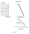
- Fig. 7is a schematic of a fiber array, microlens array and diffraction grating (array of mirrors) used to displace focused (imaged) spots in the longitudinal and transverse dimensions on the sample.
- Light from the light source(not shown) passes through the fibers in the array, and through the microlens array to the diffraction grating.
- Light directed by the gratingpasses through the objective lens and focused on the sample.
- the spotsare scanned (scan direction being indicated by the horizontal line and arrows) to create a multidimensional image.
- An alternative means for providing a high transverse resolution over a large depth of focusis the use of a filter in the back plane of the imaging lens.
- This techniquecommonly termed apodization, allows the production of either a line focus as in the axicon or a multitude of focused spots positioned along the longitudinal dimension.
- the use of annular apodization to shape a beam focushas been previously described in the literature ( M. Martinez-Corral, P. Andres, J. Ojeda-Castaneda, G. Saavedra, Opt. Comm. 119, 491 (1995 )).
- use of apodization to create high transverse resolution over a large focal distance, where the longitudinal data is further resolved by OCThas not been previously described.
- Fig. 8shows an embodiment of an apodized pupil plane filter.
- Fig. 9shows a schematic of the use of an apodizer in front of an imaging lens the output of which is focused in the axial line.
- An advantage of the present inventionis that the OCT imaging apparatus is capable of enabling sub-cellular resolution imaging along transverse and longitudinal dimensions of the sample in a compact, optical fiber-based package.
- Other advantagesinclude the potential compact size and low coat of axial line focus optical elements such as the apodizer-lem combination or axicon.
Landscapes
- Physics & Mathematics (AREA)
- General Physics & Mathematics (AREA)
- Health & Medical Sciences (AREA)
- General Health & Medical Sciences (AREA)
- Chemical & Material Sciences (AREA)
- Nuclear Medicine, Radiotherapy & Molecular Imaging (AREA)
- Biochemistry (AREA)
- Life Sciences & Earth Sciences (AREA)
- Optics & Photonics (AREA)
- Immunology (AREA)
- Pathology (AREA)
- Analytical Chemistry (AREA)
- Radiology & Medical Imaging (AREA)
- Investigating Or Analysing Materials By Optical Means (AREA)
- Length Measuring Devices By Optical Means (AREA)
- Measurement Of Optical Distance (AREA)
- Endoscopes (AREA)
- Microscoopes, Condenser (AREA)
- Instruments For Viewing The Inside Of Hollow Bodies (AREA)
Abstract
Description
- The present invention relates to apparatus for imaging tissue samples using optical coherence tomography and incorporating an optical element to improve transverse resolution and depth of focus.
- Currently, the use of optical coherence tomography (OCT) is limited to the visualization of architectural morphological structures within biological tissues. The imaging of sub-cellular features with OCT has not been well demonstrated because of the relatively poor transverse resolution required to preserve depth of focus. The capability to perform high transverse resolution, large depth of field cross-sectional OCT imaging would permit application to early diagnosis of epithelial cancers and other biomedical imaging diagnostics that require sub-cellular level resolution.
- To date, there are no known optical coherence tomography configurations that can perform high transverse resolution imaging over a large depth of field. It would be desirable to have a simple device for performing high transverse resolution, large depth of field optical coherence tomography. In addition, by allowing light delivery through a single optical fiber, this device would be also be easily incorporated into catheters or endoscopes. These properties would make this device an enabling technology for performing optical coherence tomography in applications requiring sub-cellular resolution imaging at remote sites within biological systems.
- Optical coherence tomography methods are described inJ. A. Izatt, et al.: "Optical Coherence Tomography and Microscopy in Gastrointestinal Tissues", IEEE Journal of Selected Topics in Quantum Electronics Vol. 2, No. 4, December 4, 1996;, andF. Lexer et al.: "Dynamic Coherent Focus for Transversal Resolution Enhancement of OCT" SPIE, Vol. 3251, April 1998.
- The invention is defined by the claims and is illustrated in the drawings in which like reference characters designate the same or similar parts throughout the figures of which:
Fig. 1 is a schematic view describing focusing usinga refractive axicon. A collimated beam, incident from the left, is focused to an axial line with a narrow width and large depth.Fig. 2 is a schematic view of an OCT system with axicon optic in sample arm.Fig. 3 is a schematic view of the relationship between axial location and annulus of illumination.Fig. 4A is a schematic view of the image formation.Fig. 4B is a schematic view of the translation of the entire optical assembly in the y-direction.- Fig. 4C is a schematic view of the rotation of the entire optical assembly.
- Fig. 4D is a schematic view of the angular deflection of the axial line focus in the x-y plane.
Fig. 5 is a schematic view of a system used to perform high transverse resolution ranging with a high depth of field.Fig. 6 is a schematic view of an offset fiber array.Fig. 7 is a schematic of a fiber array, microlens array and diffraction grating.Fig. 8 is a schematic view of an embodiment of an apodized pupil plane filter.Fig. 9 is a schematic view of the use of an apodizer in front of an imaging lens.- "Axicon" shall mean any optic element (or combination thereof) capable of generating an axial line focus. Refractive, diffractive, and reflective axicons have been demonstrated. See,J.H. McLeod, J. Opt. Soc. Am 44, 592 (1954);J.H. McLeod, J. Opt. Soc. Am 50, 166 (1960); andJ.R. Rayces, J. Opt. Soc. Am. 48, 576 (1958).
- "Depth of focus" shall mean the longitudinal distance over which the beam diameter increases by a factor ζ (typically ζ = sqrt(2) or 2). For a Gaussian beam, the sqrt(2) depth of focus is

- For a typical Gaussian spot size (1/e2 diameter) of d = 5 µm, and a wavelength of 830 nm, the depth of focus is approximately 48 µm. The depth of focus for a uniform beam (3 dB full-width-half-maximum intensity response for a planar reflector moved through the longitudinal plane) may be defined as

- For a NA = 0.2, which produces a spot size of 5 µm, the depth of focus for a uniform beam is approximately 17 µm at 830 nm.
- "Longitudinal" shall mean substantially parallel to the optical axis.
- "Longitudinal resolution" shall mean the minimum distance, Δz, in the longitudinal direction that two points may be separated while still being differentiated by an optical detection means.
- "Spot size" shall mean the transverse diameter of a focused spot. For a Gaussian beam, the spot size is defined as transverse width of the spot where the intensity at the focus has decreased by a factor of 1/e2. For a collimated Gaussian beam, the spot size, d, is defined as

where D is the beam diameter at the lens,ƒ is the focal length of the lens and λ is the wavelength. For a flat top or uniform beam, the spot radius is defined as the transverse position of the first zero of the Airy disk,
where
and n is the refractive index of the immersion medium. - "Transverse" shall mean substantially perpendicular to the optical axis.
- "Transverse resolution" shall mean the minimum distance, Δr, in the transverse direction that two points may be separated while still being differentiated by an optical detection means. One commonly used approximation is Δr = d (for a Gaussian beam) or Δr = w (for a uniform beam).
- An axial line focus, with a narrow transverse beam diameter and over a large length (or depth of focus), is generated. Used in conjunction with OCT, the diameter of the line focus determines the transverse resolution and the length determines the depth of field. As in standard OCT, the detection of light backreflected from sites along the axial focus is performed using a Michelson interferometer. When the light source has a finite spectral width, this configuration can be used to determine the axial location of the backreflection site. The axial resolution is determined by the coherence length of the light source.
- Those of ordinary skill in the art will appreciate that there are a variety of known devices for generating a line focus. An axicon (reflective, transmissive, or diffractive optical element ("DOE")) is an acceptable model known to those skilled in the art for this and will be the method that is used in the present invention to demonstrate use of OCT with an axial line focus to achieve high resolution imaging over large depths of field. It is to be understood that this method is illustrative and not intended to be the exclusive model. Other known models not falling under the present invention include, but are not limited to, multi-focal lenses, such as the Rayleigh-Wood lens (Optical Processing and Computting, H.H Arsenault, T. Szoplik, and B. Macukow eds., Academic Press Inc., San Diego, CA, 1989), the use of chromatic aberration to produce an array of wavelength dependent foci along the longitudinal axis, and the like.
- The following section discusses the physical principles of a representative axicon that uses refraction, as shown in
Fig. 1 . The intensity distribution of light transmitted through a refractive axicon lens (seeR. Arimoto, C. Saloma, T. Tanaka, and S. Kawata, Appl. Opt. 31, 6653 (1992)) is given by Equation (1):
where E2(R) is the intensity of the light incident on the axicon as a function of the radius R, λ, is the wavelength of the light, and β is the half angle of the light transmitted through the axicon. The cone angle α is related to β and the depth of focus, zD, by Equations (2a) and (2b):

where n is the refractive index of the axicon. The above equations can be used to determine the diameter of the axial line focus. For plane wave illumination the focus diameter is given by Equation (3):
- In the case of reflective or diffractive axicons, Equation (1) is modified, but in all cases it is the diameter of the axial focus that determines the transverse resolution of the imaging system. A theme of the present invention is that the poor transverse resolution typical of current OCT systems can be improved by changing from a standard focusing geometry in which the focal volume (power distribution) is limited in both the transverse and the axial dimensions to one in which the focal volume is limited only in the transverse direction.
- By combining the high transverse localization (and weak axial localization) of an axicon with OCT (see
Fig. 2 ), an imaging system that provides high three-dimensional localization over large field sizes can be realized. Axial resolution for this imaging technique is determined solely by the coherence length of the light source (E.A. Swanson, D. Huang, M.R. Hee, J.G. Fujimoto, C.P. Lin, and C.A. Puliafito, Opt. Lett. 17, 151 (1992)) and is given by Equation (4):
where Δλ, is the spectral width (full-width half maximum ("FWHM"))of the light source. - In a preferred embodiment, the optical element has a transverse resolution defined as λr=d0 being in the range of about 0.5 µm to about 10 µm, more preferably less than or equal to about 5 µm. The optical element preferably has a Δz = zD of at least about 50 µm.
Fig. 4A illustrates the entire OCT/axicon system of one embodiment of the present invention. All components, other than the axicon probe, are standard to OCT. The use of OCT to determine the backreflection as a function of distance along the axial line focus provides a one dimensional raster scan. This is typically accomplished by scanning the length of the interferometer reference arm. An axicon has the property each axial location of the focus corresponds to a unique annulus at the input aperture of the axicon (seeFig. 3 ). This relationship could allow the reference arm length scanning to be replaced by scanning an annulus of illumination at the axicon aperture.- Regardless of how the axial dimension is scanned, to obtain an image a scan of another axis must be performed. This second scanning dimension is usually performed at a slower rate. Methods of accomplishing this slow scanning of the secondary axis include moving the sample arm optics, including the optical fiber, collimating lens and axicon, in the y direction (see
Fig. 4B ), rotating the entire probe around the optical fiber axis (see Fig. 4C) or angularly deflecting the line focus in the x-y plane (see Fig. 4D). See, (G.J. Tearney, S.A. Boppart, B.E. Bouma, M.E. Brezinski, N.J. Weissman, J.F. Southern, and J.G. Fujimoto, Opt. Lett. 21, 543 (1996)) and (S.A. Boppart, B.E. Bouma, C. Pitris, G.J. Teamey, J.G. Fujimoto, and M.E. Brezinski, Opt. Lett. 22, 1618 (1997)). Both linear motion along the y or z axis and rotation are easily accomplished in a compact probe by use of piezoelectric transducers or mechanical or pneumatic actuators. Fig. 5 is a schematic of an alternative apparatus used to perform high transverse resolution ranging with a high depth of field. The system comprises a light source, beam redirecting element, detector, and an optical element. The optical element provides line focus and an array of focused spots on the sample.Fig. 6 shows an offset fiber array are directed by the mirror through the objective and used to displace focused (imaged) spots in the longitudinal and transverse dimensions on the sample. The spots are scanned (scan direction being indicated by the horizontal line and arrows) to create a multidimensional image.Fig. 7 is a schematic of a fiber array, microlens array and diffraction grating (array of mirrors) used to displace focused (imaged) spots in the longitudinal and transverse dimensions on the sample. Light from the light source (not shown) passes through the fibers in the array, and through the microlens array to the diffraction grating. Light directed by the grating passes through the objective lens and focused on the sample. The spots are scanned (scan direction being indicated by the horizontal line and arrows) to create a multidimensional image.- An alternative means for providing a high transverse resolution over a large depth of focus is the use of a filter in the back plane of the imaging lens. This technique, commonly termed apodization, allows the production of either a line focus as in the axicon or a multitude of focused spots positioned along the longitudinal dimension. The use of annular apodization to shape a beam focus has been previously described in the literature (M. Martinez-Corral, P. Andres, J. Ojeda-Castaneda, G. Saavedra, Opt. Comm. 119, 491 (1995)). However, use of apodization to create high transverse resolution over a large focal distance, where the longitudinal data is further resolved by OCT has not been previously described.
Fig. 8 shows an embodiment of an apodized pupil plane filter.Fig. 9 shows a schematic of the use of an apodizer in front of an imaging lens the output of which is focused in the axial line.- An advantage of the present invention is that the OCT imaging apparatus is capable of enabling sub-cellular resolution imaging along transverse and longitudinal dimensions of the sample in a compact, optical fiber-based package. Other advantages include the potential compact size and low coat of axial line focus optical elements such as the apodizer-lem combination or axicon.
- Although only a few exemplary embodiments of this invention have been described in detail above, those skilled in the art will readily appreciate that many modifications are possible in the exemplary embodiments without materially departing from the novel teachings and advantages of this invention. Accordingly, all such modifications are intended to be included within the scope of this invention as defined in the following claims.


Claims (31)
- An optical coherence tomography apparatus for imaging at least a portion of a sample, comprising:a first interferometric arrangement providing an electro-magnetic radiation; anda second axicon arrangement configured to receive the electro-magnetic radiation capable of generating an axial line focus, and configured to generate a resultant electro-magnetic intensity distribution along the axial line focus,wherein, along a particular direction of the axial line focus, the intensity distribution is approximately constant for at least a predetermined distance, and
wherein a wavelength of the electro-magnetic radiation remains approximately the same for at least the predetermined distance at which the intensity distribution is approximately constant. - The apparatus according to claim 1, wherein the second arrangement is an optical arrangement which is configured to optically image the sample.
- The apparatus according to claim 1, wherein the second arrangement is an axicon lens.
- The apparatus according to claim 1, wherein the second arrangement is a diffractive optical element.
- The apparatus according to claim 1, wherein the second arrangement is an annulus.
- The apparatus according to claim 1, wherein the second arrangement includes a combination of a diffractive element and a lens.
- The apparatus according to claim 1, wherein the second arrangement includes a combination of an apodized lens, a hologram and a diffractive element.
- The apparatus according to claim 1, wherein the intensity distribution is a Bessel beam.
- The apparatus according to claim 1, further comprising a third arrangement adapted to cooperate with the second arrangement so as to translate at least one of the intensity distribution and the sample.
- The apparatus according to claim 9, wherein the translation of the at least one of the intensity distribution and the sample produces an image which has 2 or more dimensions.
- The apparatus according to any one of the preceding claims, wherein the intensity distribution full width at half maximum is less than 10µm.
- The apparatus according to any one of the preceding claims, wherein the predetermined distance is at least 50µm.
- The apparatus according to any one of the preceding claims, wherein at least a portion of the intensity distribution includes a non-Gaussian distribution.
- The apparatus according to any one of the preceding claims, further comprising a fourth arrangement configured to receive information that is associated with the intensity distribution, and display an image on the received information.
- The apparatus according to claim 1, wherein the second arrangement is further configured to focus the received electromagnetic radiation to generate the resultant electro-magnetic intensity distribution.
- The apparatus according to claim 1, wherein the resultant electro-magnetic intensity distribution is constant in the particular direction within the sample.
- The apparatus according to any preceding claim, wherein
the first interferometric arrangement is a light source;
the second arrangement is an optical arrangement comprising an axicon lens, the optical arrangement being configured to receive the light from the light source, to generate a resultant intensity distribution as an axial line focus, and to direct the resultant intensity distribution to the sample;
the intensity distribution is approximately constant for at least a predetermined distance along the direction of the axial line focus; and
the apparatus comprises a detector for receiving light reflected from sites with the sample along the axial line focus. - An optical coherence tomography method for imaging at least a portion of a sample, comprising:a) providing an electro-magnetic radiation using an interferometric arrangement;b) receiving the electro-magnetic radiation at an axicon arrangement capable of generating an axial line focus and generating a resultant electro-magnetic intensity distribution along the axial line focus, wherein, along a particular direction of the axial line focus, the intensity distribution is approximately constant for at least a predetermined distance, and wherein a wavelength of the electro-magnetic radiation remains approximately the same for at least the predetermined distance at which the intensity distribution is approximately constant.
- The method according to claim 18, wherein step (b) is performed using an optical arrangement which is configured to optically image the sample.
- The method according to claim 18, wherein step (b) is performed using an axicon lens.
- The method according to claim 18, wherein step (b) is performed using a diffractive optical element.
- The method according to claim 18, wherein step (b) is performed using an annulus.
- The method according to claim 18, wherein step (b) is performed using a combination of a diffractive element and a lens.
- The method according to claim 18, wherein step (b) is performed using a combination of an apodized lens, a hologram and a diffractive element.
- The method according to claim 18, wherein the intensity distribution is a Bessel beam.
- The method according to claim 18, further comprising the step of (c) translating at least one of the intensity distribution and the sample.
- The method according to claim 26, wherein the translation of the at least one of the intensity distribution and the sample produces an image which has 2 or more dimensions.
- The method according to any one of claims 18 to 27, wherein the intensity distribution full width at half maximum is less than 10 µm.
- The method according to any one of claims 18 to 28, wherein the predetermined distance is at least 50 µm.
- The method according to any one of claims 18 to 29, wherein at least a portion of the intensity distribution includes a non-Gaussian distribution.
- The method according to any one of claims 18 to 30, further comprising the steps of receiving information that is associated with the intensity distribution; and displaying an image based on the received information.
Priority Applications (3)
| Application Number | Priority Date | Filing Date | Title |
|---|---|---|---|
| EP10181734.4AEP2290318B1 (en) | 2002-01-11 | 2003-01-10 | Apparatus for OCT imaging with axial line focus for improved resolution and depth of field |
| EP10181750.0AEP2290319B1 (en) | 2002-01-11 | 2003-01-10 | Apparatus for OCT imaging with axial line focus for improved resolution and depth of field |
| EP20100179690EP2327954A1 (en) | 2002-01-11 | 2003-01-10 | Apparatus for OCT imaging with axial line focus for improved resolution and depth of field |
Applications Claiming Priority (3)
| Application Number | Priority Date | Filing Date | Title |
|---|---|---|---|
| US34752802P | 2002-01-11 | 2002-01-11 | |
| US347528 | 2002-01-11 | ||
| PCT/US2003/000699WO2003060423A2 (en) | 2002-01-11 | 2003-01-10 | Apparatus for low coherence ranging |
Related Child Applications (5)
| Application Number | Title | Priority Date | Filing Date |
|---|---|---|---|
| EP10181734.4ADivisionEP2290318B1 (en) | 2002-01-11 | 2003-01-10 | Apparatus for OCT imaging with axial line focus for improved resolution and depth of field |
| EP10181750.0ADivisionEP2290319B1 (en) | 2002-01-11 | 2003-01-10 | Apparatus for OCT imaging with axial line focus for improved resolution and depth of field |
| EP10179690.2Division-Into | 2010-09-24 | ||
| EP10181750.0Division-Into | 2010-09-29 | ||
| EP10181734.4Division-Into | 2010-09-29 |
Publications (2)
| Publication Number | Publication Date |
|---|---|
| EP1468245A2 EP1468245A2 (en) | 2004-10-20 |
| EP1468245B1true EP1468245B1 (en) | 2011-03-30 |
Family
ID=32987184
Family Applications (4)
| Application Number | Title | Priority Date | Filing Date |
|---|---|---|---|
| EP03705716AExpired - LifetimeEP1468245B1 (en) | 2002-01-11 | 2003-01-10 | Apparatus for OCT imaging with axial line focus for improved resolution and depth of field |
| EP20100179690CeasedEP2327954A1 (en) | 2002-01-11 | 2003-01-10 | Apparatus for OCT imaging with axial line focus for improved resolution and depth of field |
| EP10181734.4AExpired - LifetimeEP2290318B1 (en) | 2002-01-11 | 2003-01-10 | Apparatus for OCT imaging with axial line focus for improved resolution and depth of field |
| EP10181750.0AExpired - LifetimeEP2290319B1 (en) | 2002-01-11 | 2003-01-10 | Apparatus for OCT imaging with axial line focus for improved resolution and depth of field |
Family Applications After (3)
| Application Number | Title | Priority Date | Filing Date |
|---|---|---|---|
| EP20100179690CeasedEP2327954A1 (en) | 2002-01-11 | 2003-01-10 | Apparatus for OCT imaging with axial line focus for improved resolution and depth of field |
| EP10181734.4AExpired - LifetimeEP2290318B1 (en) | 2002-01-11 | 2003-01-10 | Apparatus for OCT imaging with axial line focus for improved resolution and depth of field |
| EP10181750.0AExpired - LifetimeEP2290319B1 (en) | 2002-01-11 | 2003-01-10 | Apparatus for OCT imaging with axial line focus for improved resolution and depth of field |
Country Status (9)
| Country | Link |
|---|---|
| US (1) | US7310150B2 (en) |
| EP (4) | EP1468245B1 (en) |
| JP (1) | JP2005530128A (en) |
| CN (2) | CN1639539A (en) |
| AT (1) | ATE503982T1 (en) |
| AU (2) | AU2003207507A1 (en) |
| CA (1) | CA2473465C (en) |
| DE (1) | DE60336534D1 (en) |
| WO (1) | WO2003060423A2 (en) |
Cited By (2)
| Publication number | Priority date | Publication date | Assignee | Title |
|---|---|---|---|---|
| US9677869B2 (en) | 2012-12-05 | 2017-06-13 | Perimeter Medical Imaging, Inc. | System and method for generating a wide-field OCT image of a portion of a sample |
| US10577573B2 (en) | 2017-07-18 | 2020-03-03 | Perimeter Medical Imaging, Inc. | Sample container for stabilizing and aligning excised biological tissue samples for ex vivo analysis |
Families Citing this family (240)
| Publication number | Priority date | Publication date | Assignee | Title |
|---|---|---|---|---|
| US7231243B2 (en) | 2000-10-30 | 2007-06-12 | The General Hospital Corporation | Optical methods for tissue analysis |
| US9295391B1 (en) | 2000-11-10 | 2016-03-29 | The General Hospital Corporation | Spectrally encoded miniature endoscopic imaging probe |
| AT411269B (en)* | 2001-11-05 | 2003-11-25 | Salzburger Aluminium Ag | ALUMINUM-SILICON ALLOYS WITH IMPROVED MECHANICAL PROPERTIES |
| CA2514189A1 (en)* | 2003-01-24 | 2004-08-12 | The General Hospital Corporation | System and method for identifying tissue using low-coherence interferometry |
| EP2436307B1 (en) | 2003-03-31 | 2015-10-21 | The General Hospital Corporation | Speckle reduction in optical coherence tomography by path length encoded angular compounding |
| KR101386971B1 (en) | 2003-06-06 | 2014-04-18 | 더 제너럴 하스피탈 코포레이션 | Process and apparatus for a wavelength tunning source |
| DE202004021953U1 (en) | 2003-09-12 | 2013-06-19 | Vessix Vascular, Inc. | Selectable eccentric remodeling and / or ablation of atherosclerotic material |
| EP2280256B1 (en) | 2003-10-27 | 2016-11-16 | The General Hospital Corporation | Method and apparatus for performing optical imaging using frequency-domain interferometry |
| AU2005270037B2 (en) | 2004-07-02 | 2012-02-09 | The General Hospital Corporation | Endoscopic imaging probe comprising dual clad fibre |
| EP1782020B1 (en) | 2004-08-06 | 2012-10-03 | The General Hospital Corporation | Process, system and software arrangement for determining at least one location in a sample using an optical coherence tomography |
| EP2272421A1 (en) | 2004-08-24 | 2011-01-12 | The General Hospital Corporation | Method and apparatus for imaging of vessel segments |
| WO2006024014A2 (en) | 2004-08-24 | 2006-03-02 | The General Hospital Corporation | Process, system and software arrangement for measuring a mechanical strain and elastic properties of a sample |
| US9713730B2 (en) | 2004-09-10 | 2017-07-25 | Boston Scientific Scimed, Inc. | Apparatus and method for treatment of in-stent restenosis |
| US8396548B2 (en) | 2008-11-14 | 2013-03-12 | Vessix Vascular, Inc. | Selective drug delivery in a lumen |
| KR101257100B1 (en) | 2004-09-29 | 2013-04-22 | 더 제너럴 하스피탈 코포레이션 | System and Method for Optical Coherence Imaging |
| WO2006058346A1 (en) | 2004-11-29 | 2006-06-01 | The General Hospital Corporation | Arrangements, devices, endoscopes, catheters and methods for performing optical imaging by simultaneously illuminating and detecting multiple points on a sample |
| WO2006086700A2 (en)* | 2005-02-10 | 2006-08-17 | Lightlab Imaging, Inc. | Optical coherence tomography apparatus and methods |
| KR20080013919A (en)* | 2005-04-22 | 2008-02-13 | 더 제너럴 하스피탈 코포레이션 | Apparatus, Systems and Methods for Providing Spectral Domain Polarization Sensitive Optical Coherence Tomography |
| ES2337497T3 (en) | 2005-04-28 | 2010-04-26 | The General Hospital Corporation | EVALUATION OF CHARACTERISTICS OF THE IMAGE OF AN ANATOMICAL STRUCTURE IN IMAGES OF TOMOGRAPHY OF OPTICAL COHERENCE. |
| US9060689B2 (en) | 2005-06-01 | 2015-06-23 | The General Hospital Corporation | Apparatus, method and system for performing phase-resolved optical frequency domain imaging |
| EP2267404B1 (en) | 2005-08-09 | 2016-10-05 | The General Hospital Corporation | Apparatus and method for performing polarization-based quadrature demodulation in optical coherence tomography |
| US8784336B2 (en) | 2005-08-24 | 2014-07-22 | C. R. Bard, Inc. | Stylet apparatuses and methods of manufacture |
| US7843572B2 (en) | 2005-09-29 | 2010-11-30 | The General Hospital Corporation | Method and apparatus for optical imaging via spectral encoding |
| US20070238955A1 (en)* | 2006-01-18 | 2007-10-11 | The General Hospital Corporation | Systems and methods for generating data using one or more endoscopic microscopy techniques |
| US8145018B2 (en) | 2006-01-19 | 2012-03-27 | The General Hospital Corporation | Apparatus for obtaining information for a structure using spectrally-encoded endoscopy techniques and methods for producing one or more optical arrangements |
| DK1973466T3 (en) | 2006-01-19 | 2021-02-01 | Massachusetts Gen Hospital | BALLOON IMAGING CATHETER |
| US20090128824A1 (en)* | 2006-01-24 | 2009-05-21 | Rainer Leitgeb | Optical imaging system with extended depth of focus |
| JP4483793B2 (en)* | 2006-01-27 | 2010-06-16 | セイコーエプソン株式会社 | Microstructure manufacturing method and manufacturing apparatus |
| WO2007149602A2 (en) | 2006-02-01 | 2007-12-27 | The General Hospital Corporation | Methods and systems for providing electromagnetic radiation to at least one portion of a sample using conformal laser therapy procedures |
| JP5680829B2 (en) | 2006-02-01 | 2015-03-04 | ザ ジェネラル ホスピタル コーポレイション | A device that irradiates a sample with multiple electromagnetic radiations |
| EP2982929A1 (en) | 2006-02-24 | 2016-02-10 | The General Hospital Corporation | Methods and systems for performing angle-resolved fourier-domain optical coherence tomography |
| US8019435B2 (en) | 2006-05-02 | 2011-09-13 | Boston Scientific Scimed, Inc. | Control of arterial smooth muscle tone |
| WO2007133961A2 (en) | 2006-05-10 | 2007-11-22 | The General Hospital Corporation | Processes, arrangements and systems for providing frequency domain imaging of a sample |
| US20080024767A1 (en)* | 2006-07-28 | 2008-01-31 | Peter Seitz | Imaging optical coherence tomography with dynamic coherent focus |
| WO2008016927A2 (en)* | 2006-08-01 | 2008-02-07 | The General Hospital Corporation | Systems and methods for receiving and/or analyzing information associated with electro-magnetic radiation |
| CN100401974C (en)* | 2006-09-08 | 2008-07-16 | 浙江大学 | A method and system for realizing axial super-resolution of optical coherence tomography |
| EP2076198A4 (en) | 2006-10-18 | 2009-12-09 | Minnow Medical Inc | Inducing desirable temperature effects on body tissue |
| JP5559539B2 (en) | 2006-10-18 | 2014-07-23 | べシックス・バスキュラー・インコーポレイテッド | System that induces desirable temperature effects on body tissue |
| EP2455036B1 (en) | 2006-10-18 | 2015-07-15 | Vessix Vascular, Inc. | Tuned RF energy and electrical tissue characterization for selective treatment of target tissues |
| US8838213B2 (en) | 2006-10-19 | 2014-09-16 | The General Hospital Corporation | Apparatus and method for obtaining and providing imaging information associated with at least one portion of a sample, and effecting such portion(s) |
| US7794407B2 (en) | 2006-10-23 | 2010-09-14 | Bard Access Systems, Inc. | Method of locating the tip of a central venous catheter |
| US8388546B2 (en) | 2006-10-23 | 2013-03-05 | Bard Access Systems, Inc. | Method of locating the tip of a central venous catheter |
| US20080118886A1 (en)* | 2006-11-21 | 2008-05-22 | Rongguang Liang | Apparatus for dental oct imaging |
| EP2096990A1 (en)* | 2006-12-22 | 2009-09-09 | Koninklijke Philips Electronics N.V. | An imaging system with two imaging modalities |
| EP2104968A1 (en)* | 2007-01-19 | 2009-09-30 | The General Hospital Corporation | Rotating disk reflection for fast wavelength scanning of dispersed broadband light |
| WO2008115965A1 (en)* | 2007-03-19 | 2008-09-25 | The General Hospital Corporation | Apparatus and method for providing a noninvasive diagnosis of internal bleeding |
| US10534129B2 (en) | 2007-03-30 | 2020-01-14 | The General Hospital Corporation | System and method providing intracoronary laser speckle imaging for the detection of vulnerable plaque |
| DE112008002383T5 (en) | 2007-09-06 | 2010-06-24 | LenSx Lasers, Inc., Aliso Viejo | Precise targeting of surgical photodisruption |
| US20090073439A1 (en)* | 2007-09-15 | 2009-03-19 | The General Hospital Corporation | Apparatus, computer-accessible medium and method for measuring chemical and/or molecular compositions of coronary atherosclerotic plaques in anatomical structures |
| EP2040059A3 (en)* | 2007-09-19 | 2013-09-04 | FUJIFILM Corporation | Optical tomography imaging system, contact area detecting method and image processing method using the same, and optical tomographic image obtaining method |
| US10524691B2 (en) | 2007-11-26 | 2020-01-07 | C. R. Bard, Inc. | Needle assembly including an aligned magnetic element |
| US8781555B2 (en) | 2007-11-26 | 2014-07-15 | C. R. Bard, Inc. | System for placement of a catheter including a signal-generating stylet |
| US9521961B2 (en) | 2007-11-26 | 2016-12-20 | C. R. Bard, Inc. | Systems and methods for guiding a medical instrument |
| US10751509B2 (en) | 2007-11-26 | 2020-08-25 | C. R. Bard, Inc. | Iconic representations for guidance of an indwelling medical device |
| US8849382B2 (en) | 2007-11-26 | 2014-09-30 | C. R. Bard, Inc. | Apparatus and display methods relating to intravascular placement of a catheter |
| US10449330B2 (en) | 2007-11-26 | 2019-10-22 | C. R. Bard, Inc. | Magnetic element-equipped needle assemblies |
| US9649048B2 (en) | 2007-11-26 | 2017-05-16 | C. R. Bard, Inc. | Systems and methods for breaching a sterile field for intravascular placement of a catheter |
| ES2465915T3 (en) | 2007-11-26 | 2014-06-09 | C.R. Bard, Inc. | Integrated system for intravascular catheter placement |
| US9636031B2 (en) | 2007-11-26 | 2017-05-02 | C.R. Bard, Inc. | Stylets for use with apparatus for intravascular placement of a catheter |
| US20090225324A1 (en)* | 2008-01-17 | 2009-09-10 | The General Hospital Corporation | Apparatus for providing endoscopic high-speed optical coherence tomography |
| US11123047B2 (en) | 2008-01-28 | 2021-09-21 | The General Hospital Corporation | Hybrid systems and methods for multi-modal acquisition of intravascular imaging data and counteracting the effects of signal absorption in blood |
| US8478382B2 (en) | 2008-02-11 | 2013-07-02 | C. R. Bard, Inc. | Systems and methods for positioning a catheter |
| EP2274572A4 (en) | 2008-05-07 | 2013-08-28 | Gen Hospital Corp | SYSTEM, METHOD AND COMPUTER MEDIUM FOR MONITORING THE MOVEMENT OF VESSELS DURING A THREE-DIMENSIONAL MICROSCOPY EXAMINATION OF CORONARY ARTERIES |
| WO2010009136A2 (en) | 2008-07-14 | 2010-01-21 | The General Hospital Corporation | Apparatus and methods for color endoscopy |
| US9901714B2 (en) | 2008-08-22 | 2018-02-27 | C. R. Bard, Inc. | Catheter assembly including ECG sensor and magnetic assemblies |
| US8437833B2 (en) | 2008-10-07 | 2013-05-07 | Bard Access Systems, Inc. | Percutaneous magnetic gastrostomy |
| US8295902B2 (en) | 2008-11-11 | 2012-10-23 | Shifamed Holdings, Llc | Low profile electrode assembly |
| US9795442B2 (en) | 2008-11-11 | 2017-10-24 | Shifamed Holdings, Llc | Ablation catheters |
| EP2355737B1 (en) | 2008-11-17 | 2021-08-11 | Boston Scientific Scimed, Inc. | Selective accumulation of energy without knowledge of tissue topography |
| US9532724B2 (en) | 2009-06-12 | 2017-01-03 | Bard Access Systems, Inc. | Apparatus and method for catheter navigation using endovascular energy mapping |
| JP5795576B2 (en) | 2009-06-12 | 2015-10-14 | バード・アクセス・システムズ,インコーポレーテッド | Method of operating a computer-based medical device that uses an electrocardiogram (ECG) signal to position an intravascular device in or near the heart |
| AU2010266027B2 (en) | 2009-06-24 | 2015-05-07 | Shifamed Holdings, Llc | Steerable medical delivery devices and methods of use |
| US8920369B2 (en) | 2009-06-24 | 2014-12-30 | Shifamed Holdings, Llc | Steerable delivery sheaths |
| JP5819823B2 (en)* | 2009-07-14 | 2015-11-24 | ザ ジェネラル ホスピタル コーポレイション | Device for measuring the flow and pressure inside a blood vessel and method of operating the device |
| EP2464407A4 (en) | 2009-08-10 | 2014-04-02 | Bard Access Systems Inc | Devices and methods for endovascular electrography |
| CA2776233A1 (en)* | 2009-10-01 | 2011-08-04 | Thunder Bay Regional Research Institute | Apparatus and methods for optical coherence tomography and confocal microscopy |
| WO2011044421A1 (en) | 2009-10-08 | 2011-04-14 | C. R. Bard, Inc. | Spacers for use with an ultrasound probe |
| WO2011047053A2 (en)* | 2009-10-13 | 2011-04-21 | California Institute Of Technology | Holographically illuminated imaging devices |
| US9492322B2 (en) | 2009-11-16 | 2016-11-15 | Alcon Lensx, Inc. | Imaging surgical target tissue by nonlinear scanning |
| US8860948B2 (en)* | 2010-01-22 | 2014-10-14 | Ben Gurion University of the Negev Research and Development Authority Ltd.; Bar Ilan University | High resolution extended depth of field optical coherence tomography |
| WO2011097312A1 (en) | 2010-02-02 | 2011-08-11 | C.R. Bard, Inc. | Apparatus and method for catheter navigation and tip location |
| US8265364B2 (en) | 2010-02-05 | 2012-09-11 | Alcon Lensx, Inc. | Gradient search integrated with local imaging in laser surgical systems |
| US8414564B2 (en) | 2010-02-18 | 2013-04-09 | Alcon Lensx, Inc. | Optical coherence tomographic system for ophthalmic surgery |
| WO2011106324A2 (en)* | 2010-02-23 | 2011-09-01 | California Institute Of Technology | Nondiffracting beam detection devices for three-dimensional imaging |
| KR20130004326A (en)* | 2010-03-05 | 2013-01-09 | 더 제너럴 하스피탈 코포레이션 | Systems, methods and computer-accessible medium which provide microscopic images of at least one anatomical structure at a particular resolution |
| AU2011232335A1 (en) | 2010-03-24 | 2012-10-11 | Shifamed Holdings, Llc | Intravascular tissue disruption |
| WO2011126580A2 (en) | 2010-04-09 | 2011-10-13 | Minnow Medical, Inc. | Power generating and control apparatus for the treatment of tissue |
| US9192790B2 (en) | 2010-04-14 | 2015-11-24 | Boston Scientific Scimed, Inc. | Focused ultrasonic renal denervation |
| US9069130B2 (en) | 2010-05-03 | 2015-06-30 | The General Hospital Corporation | Apparatus, method and system for generating optical radiation from biological gain media |
| US9655677B2 (en) | 2010-05-12 | 2017-05-23 | Shifamed Holdings, Llc | Ablation catheters including a balloon and electrodes |
| AU2011252976A1 (en) | 2010-05-12 | 2012-11-08 | Shifamed Holdings, Llc | Low profile electrode assembly |
| EP2575597B1 (en) | 2010-05-25 | 2022-05-04 | The General Hospital Corporation | Apparatus for providing optical imaging of structures and compositions |
| EP2575598A2 (en) | 2010-05-25 | 2013-04-10 | The General Hospital Corporation | Apparatus, systems, methods and computer-accessible medium for spectral analysis of optical coherence tomography images |
| EP2912999B1 (en) | 2010-05-28 | 2022-06-29 | C. R. Bard, Inc. | Apparatus for use with needle insertion guidance system |
| EP4122385A1 (en) | 2010-05-28 | 2023-01-25 | C. R. Bard, Inc. | Insertion guidance system for needles and medical components |
| JP6066901B2 (en) | 2010-06-03 | 2017-01-25 | ザ ジェネラル ホスピタル コーポレイション | Method for apparatus and device for imaging structures in or in one or more luminal organs |
| US8473067B2 (en) | 2010-06-11 | 2013-06-25 | Boston Scientific Scimed, Inc. | Renal denervation and stimulation employing wireless vascular energy transfer arrangement |
| US8398236B2 (en) | 2010-06-14 | 2013-03-19 | Alcon Lensx, Inc. | Image-guided docking for ophthalmic surgical systems |
| US9358365B2 (en) | 2010-07-30 | 2016-06-07 | Boston Scientific Scimed, Inc. | Precision electrode movement control for renal nerve ablation |
| US9155589B2 (en) | 2010-07-30 | 2015-10-13 | Boston Scientific Scimed, Inc. | Sequential activation RF electrode set for renal nerve ablation |
| US9408661B2 (en) | 2010-07-30 | 2016-08-09 | Patrick A. Haverkost | RF electrodes on multiple flexible wires for renal nerve ablation |
| US9463062B2 (en) | 2010-07-30 | 2016-10-11 | Boston Scientific Scimed, Inc. | Cooled conductive balloon RF catheter for renal nerve ablation |
| US9084609B2 (en) | 2010-07-30 | 2015-07-21 | Boston Scientific Scime, Inc. | Spiral balloon catheter for renal nerve ablation |
| CN103228219B (en) | 2010-08-09 | 2016-04-27 | C·R·巴德股份有限公司 | Support and Covering Structures for Ultrasound Probe Heads |
| BR112013002431B1 (en) | 2010-08-20 | 2021-06-29 | C.R. Bard, Inc | SYSTEM FOR RECONFIRMING THE POSITION OF A CATHETER INSIDE A PATIENT |
| WO2012033957A2 (en) | 2010-09-09 | 2012-03-15 | California Institute Of Technology | Delayed emission detection devices and methods |
| US9532708B2 (en) | 2010-09-17 | 2017-01-03 | Alcon Lensx, Inc. | Electronically controlled fixation light for ophthalmic imaging systems |
| US8974451B2 (en) | 2010-10-25 | 2015-03-10 | Boston Scientific Scimed, Inc. | Renal nerve ablation using conductive fluid jet and RF energy |
| WO2012058381A2 (en) | 2010-10-27 | 2012-05-03 | The General Hospital Corporation | Apparatus, systems and methods for measuring blood pressure within at least one vessel |
| US9220558B2 (en) | 2010-10-27 | 2015-12-29 | Boston Scientific Scimed, Inc. | RF renal denervation catheter with multiple independent electrodes |
| US8801693B2 (en) | 2010-10-29 | 2014-08-12 | C. R. Bard, Inc. | Bioimpedance-assisted placement of a medical device |
| JP5535043B2 (en)* | 2010-11-08 | 2014-07-02 | 三菱電機株式会社 | Resin identification device |
| US9028485B2 (en) | 2010-11-15 | 2015-05-12 | Boston Scientific Scimed, Inc. | Self-expanding cooling electrode for renal nerve ablation |
| US9089350B2 (en) | 2010-11-16 | 2015-07-28 | Boston Scientific Scimed, Inc. | Renal denervation catheter with RF electrode and integral contrast dye injection arrangement |
| US9668811B2 (en) | 2010-11-16 | 2017-06-06 | Boston Scientific Scimed, Inc. | Minimally invasive access for renal nerve ablation |
| US9326751B2 (en) | 2010-11-17 | 2016-05-03 | Boston Scientific Scimed, Inc. | Catheter guidance of external energy for renal denervation |
| US9060761B2 (en) | 2010-11-18 | 2015-06-23 | Boston Scientific Scime, Inc. | Catheter-focused magnetic field induced renal nerve ablation |
| US9192435B2 (en) | 2010-11-22 | 2015-11-24 | Boston Scientific Scimed, Inc. | Renal denervation catheter with cooled RF electrode |
| US9023034B2 (en) | 2010-11-22 | 2015-05-05 | Boston Scientific Scimed, Inc. | Renal ablation electrode with force-activatable conduction apparatus |
| US20120157993A1 (en) | 2010-12-15 | 2012-06-21 | Jenson Mark L | Bipolar Off-Wall Electrode Device for Renal Nerve Ablation |
| US9220561B2 (en) | 2011-01-19 | 2015-12-29 | Boston Scientific Scimed, Inc. | Guide-compatible large-electrode catheter for renal nerve ablation with reduced arterial injury |
| US9999354B2 (en)* | 2011-01-21 | 2018-06-19 | National Research Council Of Canada | Biological tissue inspection method and system |
| US9086536B2 (en) | 2011-03-09 | 2015-07-21 | California Institute Of Technology | Talbot imaging devices and systems |
| WO2012127880A1 (en)* | 2011-03-24 | 2012-09-27 | 株式会社ニコン | Observation device and observation method |
| WO2012145566A2 (en) | 2011-04-20 | 2012-10-26 | California Institute Of Technology | Talbot-illuminated imaging devices, systems, and methods for focal plane tuning |
| US9179843B2 (en) | 2011-04-21 | 2015-11-10 | Hassan Ghaderi MOGHADDAM | Method and system for optically evaluating proximity to the inferior alveolar nerve in situ |
| US8459794B2 (en) | 2011-05-02 | 2013-06-11 | Alcon Lensx, Inc. | Image-processor-controlled misalignment-reduction for ophthalmic systems |
| US9622913B2 (en) | 2011-05-18 | 2017-04-18 | Alcon Lensx, Inc. | Imaging-controlled laser surgical system |
| RU2609203C2 (en) | 2011-07-06 | 2017-01-30 | Си.Ар. Бард, Инк. | Determination and calibration of needle length for needle guidance system |
| TWI447352B (en)* | 2011-07-08 | 2014-08-01 | 私立中原大學 | Optical tomography system |
| US9330092B2 (en) | 2011-07-19 | 2016-05-03 | The General Hospital Corporation | Systems, methods, apparatus and computer-accessible-medium for providing polarization-mode dispersion compensation in optical coherence tomography |
| CN103813745B (en) | 2011-07-20 | 2016-06-29 | 波士顿科学西美德公司 | In order to visualize, be directed at and to melt transcutaneous device and the method for nerve |
| EP2734264B1 (en) | 2011-07-22 | 2018-11-21 | Boston Scientific Scimed, Inc. | Nerve modulation system with a nerve modulation element positionable in a helical guide |
| USD724745S1 (en) | 2011-08-09 | 2015-03-17 | C. R. Bard, Inc. | Cap for an ultrasound probe |
| USD699359S1 (en) | 2011-08-09 | 2014-02-11 | C. R. Bard, Inc. | Ultrasound probe head |
| EP3835718B1 (en) | 2011-08-25 | 2023-07-26 | The General Hospital Corporation | Apparatus for providing micro-optical coherence tomography inside a respiratory system |
| US8398238B1 (en) | 2011-08-26 | 2013-03-19 | Alcon Lensx, Inc. | Imaging-based guidance system for ophthalmic docking using a location-orientation analysis |
| CN106823131B (en) | 2011-09-30 | 2019-12-20 | 柯惠有限合伙公司 | Energy transfer device and method of use |
| WO2013055826A1 (en) | 2011-10-10 | 2013-04-18 | Boston Scientific Scimed, Inc. | Medical devices including ablation electrodes |
| US9420955B2 (en) | 2011-10-11 | 2016-08-23 | Boston Scientific Scimed, Inc. | Intravascular temperature monitoring system and method |
| EP2765940B1 (en) | 2011-10-11 | 2015-08-26 | Boston Scientific Scimed, Inc. | Off-wall electrode device for nerve modulation |
| US9364284B2 (en) | 2011-10-12 | 2016-06-14 | Boston Scientific Scimed, Inc. | Method of making an off-wall spacer cage |
| EP2768568B1 (en) | 2011-10-18 | 2020-05-06 | Boston Scientific Scimed, Inc. | Integrated crossing balloon catheter |
| US9162046B2 (en) | 2011-10-18 | 2015-10-20 | Boston Scientific Scimed, Inc. | Deflectable medical devices |
| JP2015502562A (en) | 2011-10-18 | 2015-01-22 | ザ ジェネラル ホスピタル コーポレイション | Apparatus and method for generating and / or providing recirculating optical delay |
| US9211107B2 (en) | 2011-11-07 | 2015-12-15 | C. R. Bard, Inc. | Ruggedized ultrasound hydrogel insert |
| US8951251B2 (en) | 2011-11-08 | 2015-02-10 | Boston Scientific Scimed, Inc. | Ostial renal nerve ablation |
| WO2013074813A1 (en) | 2011-11-15 | 2013-05-23 | Boston Scientific Scimed, Inc. | Device and methods for renal nerve modulation monitoring |
| US9119632B2 (en) | 2011-11-21 | 2015-09-01 | Boston Scientific Scimed, Inc. | Deflectable renal nerve ablation catheter |
| US9023016B2 (en) | 2011-12-19 | 2015-05-05 | Alcon Lensx, Inc. | Image processor for intra-surgical optical coherence tomographic imaging of laser cataract procedures |
| US9066784B2 (en) | 2011-12-19 | 2015-06-30 | Alcon Lensx, Inc. | Intra-surgical optical coherence tomographic imaging of cataract procedures |
| US20130163003A1 (en)* | 2011-12-21 | 2013-06-27 | Ole Massow | Apparatus and method for optical swept-source coherence tomography |
| US9265969B2 (en) | 2011-12-21 | 2016-02-23 | Cardiac Pacemakers, Inc. | Methods for modulating cell function |
| US9028472B2 (en) | 2011-12-23 | 2015-05-12 | Vessix Vascular, Inc. | Methods and apparatuses for remodeling tissue of or adjacent to a body passage |
| EP2797534A1 (en) | 2011-12-28 | 2014-11-05 | Boston Scientific Scimed, Inc. | Device and methods for nerve modulation using a novel ablation catheter with polymeric ablative elements |
| US9050106B2 (en) | 2011-12-29 | 2015-06-09 | Boston Scientific Scimed, Inc. | Off-wall electrode device and methods for nerve modulation |
| JP5655805B2 (en)* | 2012-03-21 | 2015-01-21 | 住友電気工業株式会社 | Optical probe and optical measurement method |
| WO2013148306A1 (en) | 2012-03-30 | 2013-10-03 | The General Hospital Corporation | Imaging system, method and distal attachment for multidirectional field of view endoscopy |
| US8961550B2 (en) | 2012-04-17 | 2015-02-24 | Indian Wells Medical, Inc. | Steerable endoluminal punch |
| US10660703B2 (en) | 2012-05-08 | 2020-05-26 | Boston Scientific Scimed, Inc. | Renal nerve modulation devices |
| JP2015517387A (en) | 2012-05-21 | 2015-06-22 | ザ ジェネラル ホスピタル コーポレイション | Apparatus, device and method for capsule microscopy |
| EP2861153A4 (en) | 2012-06-15 | 2016-10-19 | Bard Inc C R | Apparatus and methods for detection of a removable cap on an ultrasound probe |
| JP5828811B2 (en)* | 2012-07-23 | 2015-12-09 | キヤノン株式会社 | Imaging apparatus and control method thereof |
| EP2690395A1 (en)* | 2012-07-24 | 2014-01-29 | Hexagon Technology Center GmbH | Interferometric distance measuring assembly and method |
| JP6227652B2 (en) | 2012-08-22 | 2017-11-08 | ザ ジェネラル ホスピタル コーポレイション | System, method, and computer-accessible medium for fabricating a miniature endoscope using soft lithography |
| US10321946B2 (en) | 2012-08-24 | 2019-06-18 | Boston Scientific Scimed, Inc. | Renal nerve modulation devices with weeping RF ablation balloons |
| CN104780859B (en) | 2012-09-17 | 2017-07-25 | 波士顿科学西美德公司 | Self-positioning electrode systems and methods for renal neuromodulation |
| US10398464B2 (en) | 2012-09-21 | 2019-09-03 | Boston Scientific Scimed, Inc. | System for nerve modulation and innocuous thermal gradient nerve block |
| US10549127B2 (en) | 2012-09-21 | 2020-02-04 | Boston Scientific Scimed, Inc. | Self-cooling ultrasound ablation catheter |
| CN104869930B (en) | 2012-10-10 | 2020-12-25 | 波士顿科学国际有限公司 | Renal neuromodulation apparatus and methods |
| KR20140089129A (en) | 2013-01-04 | 2014-07-14 | 삼성전자주식회사 | Optical zoom probe |
| JP6053138B2 (en)* | 2013-01-24 | 2016-12-27 | 株式会社日立エルジーデータストレージ | Optical tomographic observation apparatus and optical tomographic observation method |
| US9968261B2 (en) | 2013-01-28 | 2018-05-15 | The General Hospital Corporation | Apparatus and method for providing diffuse spectroscopy co-registered with optical frequency domain imaging |
| WO2014120791A1 (en) | 2013-01-29 | 2014-08-07 | The General Hospital Corporation | Apparatus, systems and methods for providing information regarding the aortic valve |
| US11179028B2 (en) | 2013-02-01 | 2021-11-23 | The General Hospital Corporation | Objective lens arrangement for confocal endomicroscopy |
| WO2014143571A1 (en) | 2013-03-11 | 2014-09-18 | Boston Scientific Scimed, Inc. | Medical devices for modulating nerves |
| WO2014163987A1 (en) | 2013-03-11 | 2014-10-09 | Boston Scientific Scimed, Inc. | Medical devices for modulating nerves |
| US9808311B2 (en) | 2013-03-13 | 2017-11-07 | Boston Scientific Scimed, Inc. | Deflectable medical devices |
| CN105228546B (en) | 2013-03-15 | 2017-11-14 | 波士顿科学国际有限公司 | Medical devices and methods for treating hypertension utilizing impedance compensation |
| US10478072B2 (en) | 2013-03-15 | 2019-11-19 | The General Hospital Corporation | Methods and system for characterizing an object |
| EP2967734B1 (en) | 2013-03-15 | 2019-05-15 | Boston Scientific Scimed, Inc. | Methods and apparatuses for remodeling tissue of or adjacent to a body passage |
| US10265122B2 (en) | 2013-03-15 | 2019-04-23 | Boston Scientific Scimed, Inc. | Nerve ablation devices and related methods of use |
| EP2968919B1 (en) | 2013-03-15 | 2021-08-25 | Medtronic Ardian Luxembourg S.à.r.l. | Controlled neuromodulation systems |
| KR20150140760A (en) | 2013-04-08 | 2015-12-16 | 아파마 메디칼, 인크. | Cardiac ablation catheters and methods of use thereof |
| US10349824B2 (en) | 2013-04-08 | 2019-07-16 | Apama Medical, Inc. | Tissue mapping and visualization systems |
| US10098694B2 (en) | 2013-04-08 | 2018-10-16 | Apama Medical, Inc. | Tissue ablation and monitoring thereof |
| EP2997354A4 (en) | 2013-05-13 | 2017-01-18 | The General Hospital Corporation | Detecting self-interefering fluorescence phase and amplitude |
| CN105473092B (en) | 2013-06-21 | 2019-05-17 | 波士顿科学国际有限公司 | The medical instrument for renal nerve ablation with rotatable shaft |
| CN105473091B (en) | 2013-06-21 | 2020-01-21 | 波士顿科学国际有限公司 | Renal denervation balloon catheter with co-movable electrode supports |
| US9707036B2 (en) | 2013-06-25 | 2017-07-18 | Boston Scientific Scimed, Inc. | Devices and methods for nerve modulation using localized indifferent electrodes |
| CN105358084B (en) | 2013-07-01 | 2018-11-09 | 波士顿科学国际有限公司 | Medical instrument for renal nerve ablation |
| US10413357B2 (en) | 2013-07-11 | 2019-09-17 | Boston Scientific Scimed, Inc. | Medical device with stretchable electrode assemblies |
| CN105377169B (en) | 2013-07-11 | 2019-04-19 | 波士顿科学国际有限公司 | Devices and methods for neuromodulation |
| EP3021735A4 (en) | 2013-07-19 | 2017-04-19 | The General Hospital Corporation | Determining eye motion by imaging retina. with feedback |
| US9925001B2 (en) | 2013-07-19 | 2018-03-27 | Boston Scientific Scimed, Inc. | Spiral bipolar electrode renal denervation balloon |
| WO2015009932A1 (en) | 2013-07-19 | 2015-01-22 | The General Hospital Corporation | Imaging apparatus and method which utilizes multidirectional field of view endoscopy |
| US10695124B2 (en) | 2013-07-22 | 2020-06-30 | Boston Scientific Scimed, Inc. | Renal nerve ablation catheter having twist balloon |
| US10342609B2 (en) | 2013-07-22 | 2019-07-09 | Boston Scientific Scimed, Inc. | Medical devices for renal nerve ablation |
| WO2015013651A2 (en) | 2013-07-26 | 2015-01-29 | The General Hospital Corporation | System, apparatus and method utilizing optical dispersion for fourier-domain optical coherence tomography |
| DE102013012692A1 (en)* | 2013-07-31 | 2015-02-05 | Fraunhofer-Gesellschaft zur Förderung der angewandten Forschung e.V. | Method and device for detecting foreign bodies or other scattering centers in optically transparent containers |
| CN105473093B (en) | 2013-08-22 | 2019-02-05 | 波士顿科学国际有限公司 | Flexible circuit with improved adhesion to renal neuromodulation balloon |
| US9895194B2 (en) | 2013-09-04 | 2018-02-20 | Boston Scientific Scimed, Inc. | Radio frequency (RF) balloon catheter having flushing and cooling capability |
| EP3043733A1 (en) | 2013-09-13 | 2016-07-20 | Boston Scientific Scimed, Inc. | Ablation balloon with vapor deposited cover layer |
| US11246654B2 (en) | 2013-10-14 | 2022-02-15 | Boston Scientific Scimed, Inc. | Flexible renal nerve ablation devices and related methods of use and manufacture |
| EP3057488B1 (en) | 2013-10-14 | 2018-05-16 | Boston Scientific Scimed, Inc. | High resolution cardiac mapping electrode array catheter |
| US9770606B2 (en) | 2013-10-15 | 2017-09-26 | Boston Scientific Scimed, Inc. | Ultrasound ablation catheter with cooling infusion and centering basket |
| US9962223B2 (en) | 2013-10-15 | 2018-05-08 | Boston Scientific Scimed, Inc. | Medical device balloon |
| EP3057521B1 (en) | 2013-10-18 | 2020-03-25 | Boston Scientific Scimed, Inc. | Balloon catheters with flexible conducting wires |
| CN105658163B (en) | 2013-10-25 | 2020-08-18 | 波士顿科学国际有限公司 | Embedded thermocouple in denervation flexible circuit |
| EP3091922B1 (en) | 2014-01-06 | 2018-10-17 | Boston Scientific Scimed, Inc. | Tear resistant flex circuit assembly |
| WO2015105870A1 (en) | 2014-01-08 | 2015-07-16 | The General Hospital Corporation | Method and apparatus for microscopic imaging |
| US10736494B2 (en) | 2014-01-31 | 2020-08-11 | The General Hospital Corporation | System and method for facilitating manual and/or automatic volumetric imaging with real-time tension or force feedback using a tethered imaging device |
| CN106572881B (en) | 2014-02-04 | 2019-07-26 | 波士顿科学国际有限公司 | Alternative placement of thermal sensors on bipolar electrodes |
| US11000679B2 (en) | 2014-02-04 | 2021-05-11 | Boston Scientific Scimed, Inc. | Balloon protection and rewrapping devices and related methods of use |
| WO2015120256A2 (en) | 2014-02-06 | 2015-08-13 | C.R. Bard, Inc. | Systems and methods for guidance and placement of an intravascular device |
| WO2015153982A1 (en) | 2014-04-04 | 2015-10-08 | The General Hospital Corporation | Apparatus and method for controlling propagation and/or transmission of electromagnetic radiation in flexible waveguide(s) |
| JP2017522066A (en)* | 2014-06-10 | 2017-08-10 | カール ツァイス メディテック インコーポレイテッドCarl Zeiss Meditec Inc. | Imaging system and method with improved frequency domain interferometry |
| US10912462B2 (en) | 2014-07-25 | 2021-02-09 | The General Hospital Corporation | Apparatus, devices and methods for in vivo imaging and diagnosis |
| US10973584B2 (en) | 2015-01-19 | 2021-04-13 | Bard Access Systems, Inc. | Device and method for vascular access |
| US10420537B2 (en) | 2015-03-27 | 2019-09-24 | Shifamed Holdings, Llc | Steerable medical devices, systems, and methods of use |
| JP6820864B2 (en) | 2015-04-24 | 2021-01-27 | カリラ メディカル インコーポレイテッド | Manipulable medical devices, systems and usage |
| WO2016210325A1 (en) | 2015-06-26 | 2016-12-29 | C.R. Bard, Inc. | Connector interface for ecg-based catheter positioning system |
| CN108366715A (en) | 2015-11-09 | 2018-08-03 | 施菲姆德控股有限责任公司 | Steering assembly and application method for medical treatment device |
| EP4302713A3 (en) | 2015-11-16 | 2024-03-13 | Boston Scientific Scimed, Inc. | Energy delivery devices |
| JP6644892B2 (en)* | 2015-12-20 | 2020-02-12 | アップル インコーポレイテッドApple Inc. | Light detection distance measuring sensor |
| JP6703839B2 (en)* | 2016-01-14 | 2020-06-03 | 株式会社トプコン | Ophthalmic measuring device |
| US11000207B2 (en) | 2016-01-29 | 2021-05-11 | C. R. Bard, Inc. | Multiple coil system for tracking a medical device |
| US10982947B2 (en)* | 2017-06-12 | 2021-04-20 | Sightline Innovation Inc. | System and method of surface inspection of an object using mulitplexed optical coherence tomography |
| CN108036726B (en)* | 2017-12-05 | 2020-12-22 | 中国科学院合肥物质科学研究院 | A device for measuring nanowire displacement using polarization-maintaining fibers and dual microlenses |
| JP6880513B2 (en)* | 2018-03-13 | 2021-06-02 | オムロン株式会社 | Optical measuring device and optical measuring method |
| US10992079B2 (en) | 2018-10-16 | 2021-04-27 | Bard Access Systems, Inc. | Safety-equipped connection systems and methods thereof for establishing electrical connections |
| EP3887852B1 (en) | 2019-02-11 | 2025-07-30 | Apple Inc. | Depth sensing using a sparse array of pulsed beams |
| US12306307B2 (en) | 2019-06-10 | 2025-05-20 | Apple Inc. | Selection of pulse repetition intervals for sensing time of flight |
| EP3999897B1 (en) | 2019-07-17 | 2025-06-25 | Scoptonic SP. Z.O.O. | High sensitivity optical devices using pupil splittig means |
| CN112540464A (en)* | 2019-09-20 | 2021-03-23 | 中国空气动力研究与发展中心超高速空气动力研究所 | Laser homogenization illumination light path and device |
| US11733359B2 (en) | 2019-12-03 | 2023-08-22 | Apple Inc. | Configurable array of single-photon detectors |
| US12321046B2 (en)* | 2020-02-12 | 2025-06-03 | Nthalmic Holding Pty Ltd | Spectacle lenses with auxiliary optical elements |
| US12196860B2 (en) | 2021-03-02 | 2025-01-14 | Apple Inc. | Depth sensor calibration using internal reflections |
| CN115502552B (en)* | 2022-09-13 | 2025-06-24 | 长沙麓邦光电科技有限公司 | A Bessel laser processing head with double focal depth |
| DE102023114168A1 (en) | 2023-05-30 | 2024-12-05 | Bayerische Motoren Werke Aktiengesellschaft | Method for determining a quantity characterizing a friction between a vehicle wheel and a ground, and vehicle |
Family Cites Families (170)
| Publication number | Priority date | Publication date | Assignee | Title |
|---|---|---|---|---|
| US347528A (en) | 1886-08-17 | speee | ||
| US2339754A (en) | 1941-03-04 | 1944-01-25 | Westinghouse Electric & Mfg Co | Supervisory apparatus |
| US4295738A (en) | 1979-08-30 | 1981-10-20 | United Technologies Corporation | Fiber optic strain sensor |
| US4300816A (en) | 1979-08-30 | 1981-11-17 | United Technologies Corporation | Wide band multicore optical fiber |
| US5065331A (en) | 1981-05-18 | 1991-11-12 | Vachon Reginald I | Apparatus and method for determining the stress and strain in pipes, pressure vessels, structural members and other deformable bodies |
| US4601036A (en) | 1982-09-30 | 1986-07-15 | Honeywell Inc. | Rapidly tunable laser |
| HU187188B (en) | 1982-11-25 | 1985-11-28 | Koezponti Elelmiszeripari | Device for generating radiation of controllable spectral structure |
| CH663466A5 (en) | 1983-09-12 | 1987-12-15 | Battelle Memorial Institute | METHOD AND DEVICE FOR DETERMINING THE POSITION OF AN OBJECT IN RELATION TO A REFERENCE. |
| US4631498A (en) | 1985-04-26 | 1986-12-23 | Hewlett-Packard Company | CW Laser wavemeter/frequency locking technique |
| US5040889A (en) | 1986-05-30 | 1991-08-20 | Pacific Scientific Company | Spectrometer with combined visible and ultraviolet sample illumination |
| CA1290019C (en) | 1986-06-20 | 1991-10-01 | Hideo Kuwahara | Dual balanced optical signal receiver |
| US4770492A (en) | 1986-10-28 | 1988-09-13 | Spectran Corporation | Pressure or strain sensitive optical fiber |
| CA1339426C (en) | 1987-09-01 | 1997-09-02 | Michael R. Layton | Hydrophone demodulator circuit and method |
| JPH0760273B2 (en)* | 1987-10-26 | 1995-06-28 | キヤノン株式会社 | Magnetic developer |
| FR2626367B1 (en) | 1988-01-25 | 1990-05-11 | Thomson Csf | MULTI-POINT FIBER OPTIC TEMPERATURE SENSOR |
| FR2626383B1 (en)* | 1988-01-27 | 1991-10-25 | Commissariat Energie Atomique | EXTENDED FIELD SCAN AND DEPTH CONFOCAL OPTICAL MICROSCOPY AND DEVICES FOR CARRYING OUT THE METHOD |
| US4925302A (en) | 1988-04-13 | 1990-05-15 | Hewlett-Packard Company | Frequency locking device |
| DE02012428T1 (en) | 1988-07-13 | 2005-12-15 | Optiscan Pty. Ltd., Toorak | Confocal scanning microscope |
| GB8817672D0 (en) | 1988-07-25 | 1988-09-01 | Sira Ltd | Optical apparatus |
| US4868834A (en) | 1988-09-14 | 1989-09-19 | The United States Of America As Represented By The Secretary Of The Army | System for rapidly tuning a low pressure pulsed laser |
| DE3833602A1 (en) | 1988-10-03 | 1990-02-15 | Krupp Gmbh | SPECTROMETER FOR SIMULTANEOUS INTENSITY MEASUREMENT IN DIFFERENT SPECTRAL AREAS |
| DE68925586T2 (en) | 1988-12-21 | 1996-10-24 | Massachusetts Inst Technology | METHOD FOR LASER-INDUCED FLUORESCENCE OF TISSUE |
| US5046501A (en) | 1989-01-18 | 1991-09-10 | Wayne State University | Atherosclerotic identification |
| US5317389A (en) | 1989-06-12 | 1994-05-31 | California Institute Of Technology | Method and apparatus for white-light dispersed-fringe interferometric measurement of corneal topography |
| US5039193A (en) | 1990-04-03 | 1991-08-13 | Focal Technologies Incorporated | Fibre optic single mode rotary joint |
| US5262644A (en) | 1990-06-29 | 1993-11-16 | Southwest Research Institute | Remote spectroscopy for raman and brillouin scattering |
| US5197470A (en) | 1990-07-16 | 1993-03-30 | Eastman Kodak Company | Near infrared diagnostic method and instrument |
| GB9015793D0 (en) | 1990-07-18 | 1990-09-05 | Medical Res Council | Confocal scanning optical microscope |
| US5845639A (en) | 1990-08-10 | 1998-12-08 | Board Of Regents Of The University Of Washington | Optical imaging methods |
| US5127730A (en) | 1990-08-10 | 1992-07-07 | Regents Of The University Of Minnesota | Multi-color laser scanning confocal imaging system |
| US5305759A (en) | 1990-09-26 | 1994-04-26 | Olympus Optical Co., Ltd. | Examined body interior information observing apparatus by using photo-pulses controlling gains for depths |
| US5202745A (en) | 1990-11-07 | 1993-04-13 | Hewlett-Packard Company | Polarization independent optical coherence-domain reflectometry |
| JP3035336B2 (en) | 1990-11-27 | 2000-04-24 | 興和株式会社 | Blood flow measurement device |
| US5293872A (en) | 1991-04-03 | 1994-03-15 | Alfano Robert R | Method for distinguishing between calcified atherosclerotic tissue and fibrous atherosclerotic tissue or normal cardiovascular tissue using Raman spectroscopy |
| US5748598A (en) | 1995-12-22 | 1998-05-05 | Massachusetts Institute Of Technology | Apparatus and methods for reading multilayer storage media using short coherence length sources |
| US6134003A (en) | 1991-04-29 | 2000-10-17 | Massachusetts Institute Of Technology | Method and apparatus for performing optical measurements using a fiber optic imaging guidewire, catheter or endoscope |
| JP3479069B2 (en) | 1991-04-29 | 2003-12-15 | マサチューセッツ・インステチュート・オブ・テクノロジー | Method and apparatus for optical imaging and measurement |
| US6111645A (en) | 1991-04-29 | 2000-08-29 | Massachusetts Institute Of Technology | Grating based phase control optical delay line |
| US6501551B1 (en) | 1991-04-29 | 2002-12-31 | Massachusetts Institute Of Technology | Fiber optic imaging endoscope interferometer with at least one faraday rotator |
| US5956355A (en) | 1991-04-29 | 1999-09-21 | Massachusetts Institute Of Technology | Method and apparatus for performing optical measurements using a rapidly frequency-tuned laser |
| US5465147A (en) | 1991-04-29 | 1995-11-07 | Massachusetts Institute Of Technology | Method and apparatus for acquiring images using a ccd detector array and no transverse scanner |
| US6485413B1 (en) | 1991-04-29 | 2002-11-26 | The General Hospital Corporation | Methods and apparatus for forward-directed optical scanning instruments |
| US6564087B1 (en) | 1991-04-29 | 2003-05-13 | Massachusetts Institute Of Technology | Fiber optic needle probes for optical coherence tomography imaging |
| US5441053A (en) | 1991-05-03 | 1995-08-15 | University Of Kentucky Research Foundation | Apparatus and method for multiple wavelength of tissue |
| WO1993003672A1 (en) | 1991-08-20 | 1993-03-04 | Redd Douglas C B | Optical histochemical analysis, in vivo detection and real-time guidance for ablation of abnormal tissues using a raman spectroscopic detection system |
| DE4128744C1 (en) | 1991-08-29 | 1993-04-22 | Siemens Ag, 8000 Muenchen, De | |
| US5353790A (en) | 1992-01-17 | 1994-10-11 | Board Of Regents, The University Of Texas System | Method and apparatus for optical measurement of bilirubin in tissue |
| US5248876A (en) | 1992-04-21 | 1993-09-28 | International Business Machines Corporation | Tandem linear scanning confocal imaging system with focal volumes at different heights |
| US5486701A (en) | 1992-06-16 | 1996-01-23 | Prometrix Corporation | Method and apparatus for measuring reflectance in two wavelength bands to enable determination of thin film thickness |
| US5772597A (en) | 1992-09-14 | 1998-06-30 | Sextant Medical Corporation | Surgical tool end effector |
| US5698397A (en) | 1995-06-07 | 1997-12-16 | Sri International | Up-converting reporters for biological and other assays using laser excitation techniques |
| ATE151615T1 (en) | 1992-11-18 | 1997-05-15 | Spectrascience Inc | DIAGNOSTIC IMAGE DEVICE |
| US5383467A (en) | 1992-11-18 | 1995-01-24 | Spectrascience, Inc. | Guidewire catheter and apparatus for diagnostic imaging |
| US5987346A (en) | 1993-02-26 | 1999-11-16 | Benaron; David A. | Device and method for classification of tissue |
| DE4309056B4 (en) | 1993-03-20 | 2006-05-24 | Häusler, Gerd, Prof. Dr. | Method and device for determining the distance and scattering intensity of scattering points |
| DE4310209C2 (en) | 1993-03-29 | 1996-05-30 | Bruker Medizintech | Optical stationary imaging in strongly scattering media |
| DE4314189C1 (en) | 1993-04-30 | 1994-11-03 | Bodenseewerk Geraetetech | Device for the examination of optical fibres made of glass by means of heterodyne Brillouin spectroscopy |
| EP0627643B1 (en) | 1993-06-03 | 1999-05-06 | Hamamatsu Photonics K.K. | Laser scanning optical system using axicon |
| US5803082A (en) | 1993-11-09 | 1998-09-08 | Staplevision Inc. | Omnispectramammography |
| US5983125A (en) | 1993-12-13 | 1999-11-09 | The Research Foundation Of City College Of New York | Method and apparatus for in vivo examination of subcutaneous tissues inside an organ of a body using optical spectroscopy |
| JP3261244B2 (en)* | 1993-12-17 | 2002-02-25 | ブラザー工業株式会社 | Scanning optical device |
| US5450203A (en) | 1993-12-22 | 1995-09-12 | Electroglas, Inc. | Method and apparatus for determining an objects position, topography and for imaging |
| US5590660A (en) | 1994-03-28 | 1997-01-07 | Xillix Technologies Corp. | Apparatus and method for imaging diseased tissue using integrated autofluorescence |
| DE4411017C2 (en) | 1994-03-30 | 1995-06-08 | Alexander Dr Knuettel | Optical stationary spectroscopic imaging in strongly scattering objects through special light focusing and signal detection of light of different wavelengths |
| TW275570B (en) | 1994-05-05 | 1996-05-11 | Boehringer Mannheim Gmbh | |
| US5459325A (en) | 1994-07-19 | 1995-10-17 | Molecular Dynamics, Inc. | High-speed fluorescence scanner |
| US6159445A (en) | 1994-07-20 | 2000-12-12 | Nycomed Imaging As | Light imaging contrast agents |
| EP1231496B1 (en) | 1994-08-18 | 2004-12-29 | Carl Zeiss AG | Optical coherence tomography assisted surgical apparatus |
| US5491524A (en) | 1994-10-05 | 1996-02-13 | Carl Zeiss, Inc. | Optical coherence tomography corneal mapping apparatus |
| US5817144A (en) | 1994-10-25 | 1998-10-06 | Latis, Inc. | Method for contemporaneous application OF laser energy and localized pharmacologic therapy |
| US6033721A (en) | 1994-10-26 | 2000-03-07 | Revise, Inc. | Image-based three-axis positioner for laser direct write microchemical reaction |
| US5600486A (en) | 1995-01-30 | 1997-02-04 | Lockheed Missiles And Space Company, Inc. | Color separation microlens |
| US5526338A (en) | 1995-03-10 | 1996-06-11 | Yeda Research & Development Co. Ltd. | Method and apparatus for storage and retrieval with multilayer optical disks |
| US5697373A (en) | 1995-03-14 | 1997-12-16 | Board Of Regents, The University Of Texas System | Optical method and apparatus for the diagnosis of cervical precancers using raman and fluorescence spectroscopies |
| US5735276A (en) | 1995-03-21 | 1998-04-07 | Lemelson; Jerome | Method and apparatus for scanning and evaluating matter |
| US5785651A (en) | 1995-06-07 | 1998-07-28 | Keravision, Inc. | Distance measuring confocal microscope |
| WO1997001167A1 (en) | 1995-06-21 | 1997-01-09 | Massachusetts Institute Of Technology | Apparatus and method for accessing data on multilayered optical media |
| ATA107495A (en) | 1995-06-23 | 1996-06-15 | Fercher Adolf Friedrich Dr | COHERENCE BIOMETRY AND TOMOGRAPHY WITH DYNAMIC COHERENT FOCUS |
| AU1130797A (en) | 1995-08-24 | 1997-03-19 | Purdue Research Foundation | Fluorescence lifetime-based imaging and spectroscopy in tissues and other random media |
| US6615071B1 (en) | 1995-09-20 | 2003-09-02 | Board Of Regents, The University Of Texas System | Method and apparatus for detecting vulnerable atherosclerotic plaque |
| DE19542955C2 (en) | 1995-11-17 | 1999-02-18 | Schwind Gmbh & Co Kg Herbert | endoscope |
| US5719399A (en) | 1995-12-18 | 1998-02-17 | The Research Foundation Of City College Of New York | Imaging and characterization of tissue based upon the preservation of polarized light transmitted therethrough |
| US5995868A (en) | 1996-01-23 | 1999-11-30 | University Of Kansas | System for the prediction, rapid detection, warning, prevention, or control of changes in activity states in the brain of a subject |
| US5840023A (en) | 1996-01-31 | 1998-11-24 | Oraevsky; Alexander A. | Optoacoustic imaging for medical diagnosis |
| US5843000A (en) | 1996-05-07 | 1998-12-01 | The General Hospital Corporation | Optical biopsy forceps and method of diagnosing tissue |
| ATA84696A (en) | 1996-05-14 | 1998-03-15 | Adolf Friedrich Dr Fercher | METHOD AND ARRANGEMENTS FOR INCREASING CONTRAST IN OPTICAL COHERENCE TOMOGRAPHY |
| US5795295A (en) | 1996-06-25 | 1998-08-18 | Carl Zeiss, Inc. | OCT-assisted surgical microscope with multi-coordinate manipulator |
| US5842995A (en) | 1996-06-28 | 1998-12-01 | Board Of Regents, The Univerisity Of Texas System | Spectroscopic probe for in vivo measurement of raman signals |
| US6249349B1 (en) | 1996-09-27 | 2001-06-19 | Vincent Lauer | Microscope generating a three-dimensional representation of an object |
| DE19640495C2 (en) | 1996-10-01 | 1999-12-16 | Leica Microsystems | Device for confocal surface measurement |
| US6044288A (en) | 1996-11-08 | 2000-03-28 | Imaging Diagnostics Systems, Inc. | Apparatus and method for determining the perimeter of the surface of an object being scanned |
| US5872879A (en) | 1996-11-25 | 1999-02-16 | Boston Scientific Corporation | Rotatable connecting optical fibers |
| US5871449A (en) | 1996-12-27 | 1999-02-16 | Brown; David Lloyd | Device and method for locating inflamed plaque in an artery |
| US5991697A (en) | 1996-12-31 | 1999-11-23 | The Regents Of The University Of California | Method and apparatus for optical Doppler tomographic imaging of fluid flow velocity in highly scattering media |
| US5760901A (en)* | 1997-01-28 | 1998-06-02 | Zetetic Institute | Method and apparatus for confocal interference microscopy with background amplitude reduction and compensation |
| US6010449A (en) | 1997-02-28 | 2000-01-04 | Lumend, Inc. | Intravascular catheter system for treating a vascular occlusion |
| US5968064A (en) | 1997-02-28 | 1999-10-19 | Lumend, Inc. | Catheter system for treating a vascular occlusion |
| US6120516A (en) | 1997-02-28 | 2000-09-19 | Lumend, Inc. | Method for treating vascular occlusion |
| US6201989B1 (en) | 1997-03-13 | 2001-03-13 | Biomax Technologies Inc. | Methods and apparatus for detecting the rejection of transplanted tissue |
| US5994690A (en) | 1997-03-17 | 1999-11-30 | Kulkarni; Manish D. | Image enhancement in optical coherence tomography using deconvolution |
| DE69820867T2 (en) | 1997-04-29 | 2004-11-18 | Amersham Health As | LIGHT IMAGING CONTRAST AGENTS |
| US6117128A (en) | 1997-04-30 | 2000-09-12 | Kenton W. Gregory | Energy delivery catheter and method for the use thereof |
| US5887009A (en) | 1997-05-22 | 1999-03-23 | Optical Biopsy Technologies, Inc. | Confocal optical scanning system employing a fiber laser |
| US6002480A (en) | 1997-06-02 | 1999-12-14 | Izatt; Joseph A. | Depth-resolved spectroscopic optical coherence tomography |
| JP4138027B2 (en) | 1997-06-02 | 2008-08-20 | イザット,ジョーゼフ,エイ. | Imaging Doppler flow using optical coherence tomography |
| US6208415B1 (en) | 1997-06-12 | 2001-03-27 | The Regents Of The University Of California | Birefringence imaging in biological tissue using polarization sensitive optical coherent tomography |
| US5920390A (en) | 1997-06-26 | 1999-07-06 | University Of North Carolina | Fiberoptic interferometer and associated method for analyzing tissue |
| US6048349A (en) | 1997-07-09 | 2000-04-11 | Intraluminal Therapeutics, Inc. | Systems and methods for guiding a medical instrument through a body |
| US5921926A (en) | 1997-07-28 | 1999-07-13 | University Of Central Florida | Three dimensional optical imaging colposcopy |
| US5892583A (en)* | 1997-08-21 | 1999-04-06 | Li; Ming-Chiang | High speed inspection of a sample using superbroad radiation coherent interferometer |
| US6069698A (en) | 1997-08-28 | 2000-05-30 | Olympus Optical Co., Ltd. | Optical imaging apparatus which radiates a low coherence light beam onto a test object, receives optical information from light scattered by the object, and constructs therefrom a cross-sectional image of the object |
| US5920373A (en) | 1997-09-24 | 1999-07-06 | Heidelberg Engineering Optische Messysteme Gmbh | Method and apparatus for determining optical characteristics of a cornea |
| US6193676B1 (en) | 1997-10-03 | 2001-02-27 | Intraluminal Therapeutics, Inc. | Guide wire assembly |
| US5951482A (en) | 1997-10-03 | 1999-09-14 | Intraluminal Therapeutics, Inc. | Assemblies and methods for advancing a guide wire through body tissue |
| US6091984A (en) | 1997-10-10 | 2000-07-18 | Massachusetts Institute Of Technology | Measuring tissue morphology |
| US6134010A (en) | 1997-11-07 | 2000-10-17 | Lucid, Inc. | Imaging system using polarization effects to enhance image quality |
| US6048742A (en) | 1998-02-26 | 2000-04-11 | The United States Of America As Represented By The Secretary Of The Air Force | Process for measuring the thickness and composition of thin semiconductor films deposited on semiconductor wafers |
| US6831781B2 (en) | 1998-02-26 | 2004-12-14 | The General Hospital Corporation | Confocal microscopy with multi-spectral encoding and system and apparatus for spectroscopically encoded confocal microscopy |
| JP4709969B2 (en) | 1998-02-26 | 2011-06-29 | ザ ジェネラル ホスピタル コーポレイション | Confocal microscopy using multispectral coding |
| US6066102A (en) | 1998-03-09 | 2000-05-23 | Spectrascience, Inc. | Optical biopsy forceps system and method of diagnosing tissue |
| US6151522A (en) | 1998-03-16 | 2000-11-21 | The Research Foundation Of Cuny | Method and system for examining biological materials using low power CW excitation raman spectroscopy |
| US6384915B1 (en) | 1998-03-30 | 2002-05-07 | The Regents Of The University Of California | Catheter guided by optical coherence domain reflectometry |
| US6175669B1 (en) | 1998-03-30 | 2001-01-16 | The Regents Of The Universtiy Of California | Optical coherence domain reflectometry guidewire |
| DE19814057B4 (en) | 1998-03-30 | 2009-01-02 | Carl Zeiss Meditec Ag | Arrangement for optical coherence tomography and coherence topography |
| WO1999057507A1 (en) | 1998-05-01 | 1999-11-11 | Board Of Regents, The University Of Texas System | Method and apparatus for subsurface imaging |
| US6053613A (en) | 1998-05-15 | 2000-04-25 | Carl Zeiss, Inc. | Optical coherence tomography with new interferometer |
| US6549801B1 (en)* | 1998-06-11 | 2003-04-15 | The Regents Of The University Of California | Phase-resolved optical coherence tomography and optical doppler tomography for imaging fluid flow in tissue with fast scanning speed and high velocity sensitivity |
| AU5101699A (en) | 1998-07-15 | 2000-02-07 | Corazon Technologies, Inc. | Methods and devices for reducing the mineral content of vascular calcified lesions |
| US6166373A (en) | 1998-07-21 | 2000-12-26 | The Institute For Technology Development | Focal plane scanner with reciprocating spatial window |
| WO2000019889A1 (en) | 1998-10-08 | 2000-04-13 | University Of Kentucky Research Foundation | Methods and apparatus for in vivo identification and characterization of vulnerable atherosclerotic plaques |
| US6324419B1 (en) | 1998-10-27 | 2001-11-27 | Nejat Guzelsu | Apparatus and method for non-invasive measurement of stretch |
| US6191862B1 (en) | 1999-01-20 | 2001-02-20 | Lightlab Imaging, Llc | Methods and apparatus for high speed longitudinal scanning in imaging systems |
| US6272376B1 (en) | 1999-01-22 | 2001-08-07 | Cedars-Sinai Medical Center | Time-resolved, laser-induced fluorescence for the characterization of organic material |
| US6445944B1 (en) | 1999-02-01 | 2002-09-03 | Scimed Life Systems | Medical scanning system and related method of scanning |
| US6615072B1 (en) | 1999-02-04 | 2003-09-02 | Olympus Optical Co., Ltd. | Optical imaging device |
| US6185271B1 (en) | 1999-02-16 | 2001-02-06 | Richard Estyn Kinsinger | Helical computed tomography with feedback scan control |
| CA2367804A1 (en) | 1999-03-29 | 2000-10-05 | Mark A. Hamm | Single mode optical fiber coupling systems |
| US6353693B1 (en) | 1999-05-31 | 2002-03-05 | Sanyo Electric Co., Ltd. | Optical communication device and slip ring unit for an electronic component-mounting apparatus |
| US6208887B1 (en) | 1999-06-24 | 2001-03-27 | Richard H. Clarke | Catheter-delivered low resolution Raman scattering analyzing system for detecting lesions |
| US7426409B2 (en) | 1999-06-25 | 2008-09-16 | Board Of Regents, The University Of Texas System | Method and apparatus for detecting vulnerable atherosclerotic plaque |
| DE60020566T2 (en) | 1999-07-30 | 2006-05-04 | Boston Scientific Ltd., St. Michael | CATHETER WITH DRIVE AND CLUTCH FOR TURNING AND LENGTH SHIFTING |
| US6687010B1 (en)* | 1999-09-09 | 2004-02-03 | Olympus Corporation | Rapid depth scanning optical imaging device |
| US6198956B1 (en) | 1999-09-30 | 2001-03-06 | Oti Ophthalmic Technologies Inc. | High speed sector scanning apparatus having digital electronic control |
| US6308092B1 (en) | 1999-10-13 | 2001-10-23 | C. R. Bard Inc. | Optical fiber tissue localization device |
| US6393312B1 (en) | 1999-10-13 | 2002-05-21 | C. R. Bard, Inc. | Connector for coupling an optical fiber tissue localization device to a light source |
| WO2001038820A1 (en) | 1999-11-24 | 2001-05-31 | Haag-Streit Ag | Method and device for measuring the optical properties of at least two regions located at a distance from one another in a transparent and/or diffuse object |
| EP1240476A1 (en) | 1999-12-09 | 2002-09-18 | Oti Ophthalmic Technologies Inc. | Optical mapping apparatus with adjustable depth resolution |
| US6680780B1 (en) | 1999-12-23 | 2004-01-20 | Agere Systems, Inc. | Interferometric probe stabilization relative to subject movement |
| AU2001259435A1 (en) | 2000-05-03 | 2001-11-12 | Stephen T Flock | Optical imaging of subsurface anatomical structures and biomolecules |
| JP4460117B2 (en) | 2000-06-29 | 2010-05-12 | 独立行政法人理化学研究所 | Grism |
| US7231243B2 (en) | 2000-10-30 | 2007-06-12 | The General Hospital Corporation | Optical methods for tissue analysis |
| US9295391B1 (en) | 2000-11-10 | 2016-03-29 | The General Hospital Corporation | Spectrally encoded miniature endoscopic imaging probe |
| US6665075B2 (en) | 2000-11-14 | 2003-12-16 | Wm. Marshurice University | Interferometric imaging system and method |
| US6558324B1 (en) | 2000-11-22 | 2003-05-06 | Siemens Medical Solutions, Inc., Usa | System and method for strain image display |
| US6687007B1 (en) | 2000-12-14 | 2004-02-03 | Kestrel Corporation | Common path interferometer for spectral image generation |
| EP1700573A3 (en) | 2000-12-28 | 2010-12-01 | Palomar Medical Technologies, Inc. | Apparatus for therapeutic EMR treatment of the skin |
| US6515752B2 (en) | 2000-12-28 | 2003-02-04 | Coretek, Inc. | Wavelength monitoring system |
| EP1358443A2 (en) | 2001-01-22 | 2003-11-05 | Jonathan E. Roth | Method and apparatus for polarization-sensitive optical coherence tomography |
| US6552796B2 (en) | 2001-04-06 | 2003-04-22 | Lightlab Imaging, Llc | Apparatus and method for selective data collection and signal to noise ratio enhancement using optical coherence tomography |
| DE10118760A1 (en) | 2001-04-17 | 2002-10-31 | Med Laserzentrum Luebeck Gmbh | Procedure for determining the runtime distribution and arrangement |
| WO2002088684A1 (en) | 2001-04-30 | 2002-11-07 | The General Hospital Corporation | Method and apparatus for improving image clarity and sensitivity in optical coherence tomography using dynamic feedback to control focal properties and coherence gating |
| US20040166593A1 (en) | 2001-06-22 | 2004-08-26 | Nolte David D. | Adaptive interferometric multi-analyte high-speed biosensor |
| US6685885B2 (en) | 2001-06-22 | 2004-02-03 | Purdue Research Foundation | Bio-optical compact dist system |
| US20030045798A1 (en) | 2001-09-04 | 2003-03-06 | Richard Hular | Multisensor probe for tissue identification |
| US6980299B1 (en) | 2001-10-16 | 2005-12-27 | General Hospital Corporation | Systems and methods for imaging a sample |
| US7006231B2 (en) | 2001-10-18 | 2006-02-28 | Scimed Life Systems, Inc. | Diffraction grating based interferometric systems and methods |
| US6947787B2 (en) | 2001-12-21 | 2005-09-20 | Advanced Cardiovascular Systems, Inc. | System and methods for imaging within a body lumen |
| US20030236443A1 (en) | 2002-04-19 | 2003-12-25 | Cespedes Eduardo Ignacio | Methods and apparatus for the identification and stabilization of vulnerable plaque |
| EP1426799A3 (en) | 2002-11-29 | 2005-05-18 | Matsushita Electric Industrial Co., Ltd. | Optical demultiplexer, optical multi-/demultiplexer, and optical device |
| US7376455B2 (en) | 2003-05-22 | 2008-05-20 | Scimed Life Systems, Inc. | Systems and methods for dynamic optical imaging |
- 2003
- 2003-01-10EPEP03705716Apatent/EP1468245B1/ennot_activeExpired - Lifetime
- 2003-01-10EPEP20100179690patent/EP2327954A1/ennot_activeCeased
- 2003-01-10CACA2473465Apatent/CA2473465C/ennot_activeExpired - Fee Related
- 2003-01-10USUS10/501,268patent/US7310150B2/ennot_activeExpired - Lifetime
- 2003-01-10EPEP10181734.4Apatent/EP2290318B1/ennot_activeExpired - Lifetime
- 2003-01-10WOPCT/US2003/000699patent/WO2003060423A2/enactiveApplication Filing
- 2003-01-10CNCNA03805597XApatent/CN1639539A/enactivePending
- 2003-01-10AUAU2003207507Apatent/AU2003207507A1/ennot_activeAbandoned
- 2003-01-10JPJP2003560471Apatent/JP2005530128A/enactivePending
- 2003-01-10CNCN2009101270098Apatent/CN101598685B/ennot_activeExpired - Lifetime
- 2003-01-10ATAT03705716Tpatent/ATE503982T1/ennot_activeIP Right Cessation
- 2003-01-10DEDE60336534Tpatent/DE60336534D1/ennot_activeExpired - Lifetime
- 2003-01-10EPEP10181750.0Apatent/EP2290319B1/ennot_activeExpired - Lifetime
- 2009
- 2009-06-15AUAU2009202383Apatent/AU2009202383B2/ennot_activeCeased
Non-Patent Citations (5)
| Title |
|---|
| DING Z. ET AL: "High-resolution optical coherence tomography over a large depth range with an axicon lens", OPTICS LETTERS, vol. 27, no. 4, 15 February 2002 (2002-02-15), pages 243 - 245, XP007906548* |
| IZATT J.A. ET AL: "Optical Coherence Tomography and Microscopy in Gastrointestinal Tissues", IEEE JOURNAL OF SELECTED TOPICS IN QUANTUM ELECTRONICS, vol. 2, no. 4, 4 December 1996 (1996-12-04), pages 1017 - 1028, XP002186809* |
| LEXER F. ET AL: "Dynamic coherent focus for transversal resolution enhancement of OCT", PROC. SPIE, vol. 3251, April 1998 (1998-04-01), pages 85 - 90, XP007906546* |
| MARTINEZ-CORRAL M. ET AL: "Improvement of three-dimensional resolution in confocal scanning microscopy by combination of two pupil filters", OPTIK, vol. 107, no. 4, 1998, pages 145 - 148, XP007906547* |
| MARTINEZ-CORRAL M. ET AL: "Three-dimensional superresolution by annulr binary filters", OPTICS COMMUNICATIONS, vol. 165, 15 July 1999 (1999-07-15), pages 267 - 278, XP004173015* |
Cited By (4)
| Publication number | Priority date | Publication date | Assignee | Title |
|---|---|---|---|---|
| US9677869B2 (en) | 2012-12-05 | 2017-06-13 | Perimeter Medical Imaging, Inc. | System and method for generating a wide-field OCT image of a portion of a sample |
| US10359271B2 (en) | 2012-12-05 | 2019-07-23 | Perimeter Medical Imaging, Inc. | System and method for tissue differentiation in imaging |
| US10577573B2 (en) | 2017-07-18 | 2020-03-03 | Perimeter Medical Imaging, Inc. | Sample container for stabilizing and aligning excised biological tissue samples for ex vivo analysis |
| US10894939B2 (en) | 2017-07-18 | 2021-01-19 | Perimeter Medical Imaging, Inc. | Sample container for stabilizing and aligning excised biological tissue samples for ex vivo analysis |
Also Published As
| Publication number | Publication date |
|---|---|
| CA2473465A1 (en) | 2003-07-24 |
| CN101598685B (en) | 2013-11-06 |
| AU2003207507A2 (en) | 2003-07-30 |
| CN1639539A (en) | 2005-07-13 |
| WO2003060423A3 (en) | 2003-12-11 |
| EP2290319A1 (en) | 2011-03-02 |
| AU2009202383A1 (en) | 2009-07-09 |
| EP2327954A1 (en) | 2011-06-01 |
| AU2003207507A1 (en) | 2003-07-30 |
| CA2473465C (en) | 2011-04-05 |
| AU2009202383B2 (en) | 2012-09-13 |
| EP2290319B1 (en) | 2015-08-26 |
| EP1468245A2 (en) | 2004-10-20 |
| EP2290318B1 (en) | 2015-08-26 |
| ATE503982T1 (en) | 2011-04-15 |
| US7310150B2 (en) | 2007-12-18 |
| US20050018200A1 (en) | 2005-01-27 |
| WO2003060423A8 (en) | 2005-05-19 |
| EP2290318A1 (en) | 2011-03-02 |
| JP2005530128A (en) | 2005-10-06 |
| CN101598685A (en) | 2009-12-09 |
| WO2003060423A2 (en) | 2003-07-24 |
| DE60336534D1 (en) | 2011-05-12 |
Similar Documents
| Publication | Publication Date | Title |
|---|---|---|
| EP1468245B1 (en) | Apparatus for OCT imaging with axial line focus for improved resolution and depth of field | |
| US8676013B2 (en) | Imaging system using and related techniques | |
| US7477401B2 (en) | Trench measurement system employing a chromatic confocal height sensor and a microscope | |
| US8773757B2 (en) | Slit-scan multi-wavelength confocal lens module and slit-scan microscopic system and method using the same | |
| US20080024767A1 (en) | Imaging optical coherence tomography with dynamic coherent focus | |
| AU2003215503A1 (en) | Low-coherence inferometric device for light-optical scanning of an object | |
| EP1887312A1 (en) | Imaging optical coherence tomography with dynamic coherent Focus | |
| Ruprecht et al. | Confocal micro-optical distance sensor: principle and design | |
| Sato et al. | Signal processing and artificial intelligence for dual-detection confocal probes | |
| CN109489544A (en) | Super-resolution optical coherent chromatography method and system based on optical microstructures | |
| JP2020198999A (en) | Optical interference tomographic imaging apparatus | |
| Quercioli et al. | An optical probe based on spherical aberration for surface figure testing | |
| Sagan et al. | Noncontact dimensional measurement system using holographic scanning |
Legal Events
| Date | Code | Title | Description |
|---|---|---|---|
| PUAI | Public reference made under article 153(3) epc to a published international application that has entered the european phase | Free format text:ORIGINAL CODE: 0009012 | |
| 17P | Request for examination filed | Effective date:20040811 | |
| AK | Designated contracting states | Kind code of ref document:A2 Designated state(s):AT BE BG CH CY CZ DE DK EE ES FI FR GB GR HU IE IT LI LU MC NL PT SE SI SK TR | |
| AX | Request for extension of the european patent | Extension state:AL LT LV MK RO | |
| RIN1 | Information on inventor provided before grant (corrected) | Inventor name:TEARNEY, GUILLERMO, J. Inventor name:BOUMA, BRETT, EUGENE | |
| 17Q | First examination report despatched | Effective date:20081210 | |
| GRAP | Despatch of communication of intention to grant a patent | Free format text:ORIGINAL CODE: EPIDOSNIGR1 | |
| RIC1 | Information provided on ipc code assigned before grant | Ipc:G01B 9/02 20060101AFI20100928BHEP | |
| RTI1 | Title (correction) | Free format text:APPARATUS FOR OCT IMAGING WITH AXIAL LINE FOCUS FOR IMPROVED RESOLUTION AND DEPTH OF FIELD | |
| GRAS | Grant fee paid | Free format text:ORIGINAL CODE: EPIDOSNIGR3 | |
| GRAA | (expected) grant | Free format text:ORIGINAL CODE: 0009210 | |
| AK | Designated contracting states | Kind code of ref document:B1 Designated state(s):AT BE BG CH CY CZ DE DK EE ES FI FR GB GR HU IE IT LI LU MC NL PT SE SI SK TR | |
| REG | Reference to a national code | Ref country code:GB Ref legal event code:FG4D | |
| REG | Reference to a national code | Ref country code:CH Ref legal event code:EP | |
| REG | Reference to a national code | Ref country code:IE Ref legal event code:FG4D | |
| REF | Corresponds to: | Ref document number:60336534 Country of ref document:DE Date of ref document:20110512 Kind code of ref document:P | |
| REG | Reference to a national code | Ref country code:DE Ref legal event code:R096 Ref document number:60336534 Country of ref document:DE Effective date:20110512 | |
| REG | Reference to a national code | Ref country code:NL Ref legal event code:VDEP Effective date:20110330 | |
| PG25 | Lapsed in a contracting state [announced via postgrant information from national office to epo] | Ref country code:GR Free format text:LAPSE BECAUSE OF FAILURE TO SUBMIT A TRANSLATION OF THE DESCRIPTION OR TO PAY THE FEE WITHIN THE PRESCRIBED TIME-LIMIT Effective date:20110701 Ref country code:SE Free format text:LAPSE BECAUSE OF FAILURE TO SUBMIT A TRANSLATION OF THE DESCRIPTION OR TO PAY THE FEE WITHIN THE PRESCRIBED TIME-LIMIT Effective date:20110330 | |
| PG25 | Lapsed in a contracting state [announced via postgrant information from national office to epo] | Ref country code:SI Free format text:LAPSE BECAUSE OF FAILURE TO SUBMIT A TRANSLATION OF THE DESCRIPTION OR TO PAY THE FEE WITHIN THE PRESCRIBED TIME-LIMIT Effective date:20110330 Ref country code:AT Free format text:LAPSE BECAUSE OF FAILURE TO SUBMIT A TRANSLATION OF THE DESCRIPTION OR TO PAY THE FEE WITHIN THE PRESCRIBED TIME-LIMIT Effective date:20110330 Ref country code:CY Free format text:LAPSE BECAUSE OF FAILURE TO SUBMIT A TRANSLATION OF THE DESCRIPTION OR TO PAY THE FEE WITHIN THE PRESCRIBED TIME-LIMIT Effective date:20110330 Ref country code:FI Free format text:LAPSE BECAUSE OF FAILURE TO SUBMIT A TRANSLATION OF THE DESCRIPTION OR TO PAY THE FEE WITHIN THE PRESCRIBED TIME-LIMIT Effective date:20110330 | |
| PG25 | Lapsed in a contracting state [announced via postgrant information from national office to epo] | Ref country code:BE Free format text:LAPSE BECAUSE OF FAILURE TO SUBMIT A TRANSLATION OF THE DESCRIPTION OR TO PAY THE FEE WITHIN THE PRESCRIBED TIME-LIMIT Effective date:20110330 | |
| PG25 | Lapsed in a contracting state [announced via postgrant information from national office to epo] | Ref country code:PT Free format text:LAPSE BECAUSE OF FAILURE TO SUBMIT A TRANSLATION OF THE DESCRIPTION OR TO PAY THE FEE WITHIN THE PRESCRIBED TIME-LIMIT Effective date:20110801 Ref country code:EE Free format text:LAPSE BECAUSE OF FAILURE TO SUBMIT A TRANSLATION OF THE DESCRIPTION OR TO PAY THE FEE WITHIN THE PRESCRIBED TIME-LIMIT Effective date:20110330 | |
| PG25 | Lapsed in a contracting state [announced via postgrant information from national office to epo] | Ref country code:CZ Free format text:LAPSE BECAUSE OF FAILURE TO SUBMIT A TRANSLATION OF THE DESCRIPTION OR TO PAY THE FEE WITHIN THE PRESCRIBED TIME-LIMIT Effective date:20110330 Ref country code:ES Free format text:LAPSE BECAUSE OF FAILURE TO SUBMIT A TRANSLATION OF THE DESCRIPTION OR TO PAY THE FEE WITHIN THE PRESCRIBED TIME-LIMIT Effective date:20110711 Ref country code:SK Free format text:LAPSE BECAUSE OF FAILURE TO SUBMIT A TRANSLATION OF THE DESCRIPTION OR TO PAY THE FEE WITHIN THE PRESCRIBED TIME-LIMIT Effective date:20110330 | |
| PG25 | Lapsed in a contracting state [announced via postgrant information from national office to epo] | Ref country code:NL Free format text:LAPSE BECAUSE OF FAILURE TO SUBMIT A TRANSLATION OF THE DESCRIPTION OR TO PAY THE FEE WITHIN THE PRESCRIBED TIME-LIMIT Effective date:20110330 | |
| PLBE | No opposition filed within time limit | Free format text:ORIGINAL CODE: 0009261 | |
| STAA | Information on the status of an ep patent application or granted ep patent | Free format text:STATUS: NO OPPOSITION FILED WITHIN TIME LIMIT | |
| PG25 | Lapsed in a contracting state [announced via postgrant information from national office to epo] | Ref country code:DK Free format text:LAPSE BECAUSE OF FAILURE TO SUBMIT A TRANSLATION OF THE DESCRIPTION OR TO PAY THE FEE WITHIN THE PRESCRIBED TIME-LIMIT Effective date:20110330 | |
| 26N | No opposition filed | Effective date:20120102 | |
| REG | Reference to a national code | Ref country code:DE Ref legal event code:R097 Ref document number:60336534 Country of ref document:DE Effective date:20120102 | |
| PG25 | Lapsed in a contracting state [announced via postgrant information from national office to epo] | Ref country code:IT Free format text:LAPSE BECAUSE OF FAILURE TO SUBMIT A TRANSLATION OF THE DESCRIPTION OR TO PAY THE FEE WITHIN THE PRESCRIBED TIME-LIMIT Effective date:20110330 | |
| PG25 | Lapsed in a contracting state [announced via postgrant information from national office to epo] | Ref country code:MC Free format text:LAPSE BECAUSE OF NON-PAYMENT OF DUE FEES Effective date:20120131 | |
| REG | Reference to a national code | Ref country code:CH Ref legal event code:PL | |
| REG | Reference to a national code | Ref country code:IE Ref legal event code:MM4A | |
| PG25 | Lapsed in a contracting state [announced via postgrant information from national office to epo] | Ref country code:CH Free format text:LAPSE BECAUSE OF NON-PAYMENT OF DUE FEES Effective date:20120131 Ref country code:LI Free format text:LAPSE BECAUSE OF NON-PAYMENT OF DUE FEES Effective date:20120131 | |
| PG25 | Lapsed in a contracting state [announced via postgrant information from national office to epo] | Ref country code:IE Free format text:LAPSE BECAUSE OF NON-PAYMENT OF DUE FEES Effective date:20120110 | |
| PG25 | Lapsed in a contracting state [announced via postgrant information from national office to epo] | Ref country code:BG Free format text:LAPSE BECAUSE OF FAILURE TO SUBMIT A TRANSLATION OF THE DESCRIPTION OR TO PAY THE FEE WITHIN THE PRESCRIBED TIME-LIMIT Effective date:20110630 | |
| PG25 | Lapsed in a contracting state [announced via postgrant information from national office to epo] | Ref country code:TR Free format text:LAPSE BECAUSE OF FAILURE TO SUBMIT A TRANSLATION OF THE DESCRIPTION OR TO PAY THE FEE WITHIN THE PRESCRIBED TIME-LIMIT Effective date:20110330 | |
| PG25 | Lapsed in a contracting state [announced via postgrant information from national office to epo] | Ref country code:LU Free format text:LAPSE BECAUSE OF NON-PAYMENT OF DUE FEES Effective date:20120110 | |
| PG25 | Lapsed in a contracting state [announced via postgrant information from national office to epo] | Ref country code:HU Free format text:LAPSE BECAUSE OF FAILURE TO SUBMIT A TRANSLATION OF THE DESCRIPTION OR TO PAY THE FEE WITHIN THE PRESCRIBED TIME-LIMIT Effective date:20030110 | |
| REG | Reference to a national code | Ref country code:FR Ref legal event code:PLFP Year of fee payment:13 | |
| REG | Reference to a national code | Ref country code:FR Ref legal event code:PLFP Year of fee payment:14 | |
| REG | Reference to a national code | Ref country code:FR Ref legal event code:PLFP Year of fee payment:15 | |
| REG | Reference to a national code | Ref country code:FR Ref legal event code:PLFP Year of fee payment:16 | |
| PGFP | Annual fee paid to national office [announced via postgrant information from national office to epo] | Ref country code:GB Payment date:20220127 Year of fee payment:20 Ref country code:DE Payment date:20220127 Year of fee payment:20 | |
| PGFP | Annual fee paid to national office [announced via postgrant information from national office to epo] | Ref country code:FR Payment date:20220125 Year of fee payment:20 | |
| REG | Reference to a national code | Ref country code:DE Ref legal event code:R071 Ref document number:60336534 Country of ref document:DE | |
| REG | Reference to a national code | Ref country code:GB Ref legal event code:PE20 Expiry date:20230109 | |
| PG25 | Lapsed in a contracting state [announced via postgrant information from national office to epo] | Ref country code:GB Free format text:LAPSE BECAUSE OF EXPIRATION OF PROTECTION Effective date:20230109 |