EP1462205B1 - A combination of first and a second extruded frame members to be joined to each other by friction stir welding - Google Patents
A combination of first and a second extruded frame members to be joined to each other by friction stir weldingDownload PDFInfo
- Publication number
- EP1462205B1 EP1462205B1EP04011030AEP04011030AEP1462205B1EP 1462205 B1EP1462205 B1EP 1462205B1EP 04011030 AEP04011030 AEP 04011030AEP 04011030 AEP04011030 AEP 04011030AEP 1462205 B1EP1462205 B1EP 1462205B1
- Authority
- EP
- European Patent Office
- Prior art keywords
- plates
- thickened
- frame member
- extruded
- members
- Prior art date
- Legal status (The legal status is an assumption and is not a legal conclusion. Google has not performed a legal analysis and makes no representation as to the accuracy of the status listed.)
- Expired - Lifetime
Links
- 238000003466weldingMethods0.000titleclaimsdescription56
- 238000003756stirringMethods0.000titleclaimsdescription34
- 238000005304joiningMethods0.000description57
- 239000000463materialSubstances0.000description11
- 229910052751metalInorganic materials0.000description9
- 239000002184metalSubstances0.000description9
- 238000000034methodMethods0.000description9
- 238000005520cutting processMethods0.000description7
- 238000010276constructionMethods0.000description6
- 238000003801millingMethods0.000description6
- 238000000227grindingMethods0.000description4
- 238000003754machiningMethods0.000description4
- 229910000838Al alloyInorganic materials0.000description3
- 229910052782aluminiumInorganic materials0.000description3
- XAGFODPZIPBFFR-UHFFFAOYSA-NaluminiumChemical compound[Al]XAGFODPZIPBFFR-UHFFFAOYSA-N0.000description3
- 238000004519manufacturing processMethods0.000description3
- 238000005452bendingMethods0.000description2
- 238000007730finishing processMethods0.000description2
- 239000010935stainless steelSubstances0.000description2
- 229910001220stainless steelInorganic materials0.000description2
- RYGMFSIKBFXOCR-UHFFFAOYSA-NCopperChemical compound[Cu]RYGMFSIKBFXOCR-UHFFFAOYSA-N0.000description1
- 229910001200FerrotitaniumInorganic materials0.000description1
- RTAQQCXQSZGOHL-UHFFFAOYSA-NTitaniumChemical compound[Ti]RTAQQCXQSZGOHL-UHFFFAOYSA-N0.000description1
- 230000001154acute effectEffects0.000description1
- 229910045601alloyInorganic materials0.000description1
- 239000000956alloySubstances0.000description1
- 239000010953base metalSubstances0.000description1
- 239000010949copperSubstances0.000description1
- 229910052802copperInorganic materials0.000description1
- 230000000994depressogenic effectEffects0.000description1
- 239000011261inert gasSubstances0.000description1
- 150000002739metalsChemical class0.000description1
- 230000003287optical effectEffects0.000description1
- 239000004033plasticSubstances0.000description1
- 238000004023plastic weldingMethods0.000description1
- 238000003825pressingMethods0.000description1
- 239000007790solid phaseSubstances0.000description1
- 229920001169thermoplasticPolymers0.000description1
- 239000004416thermosoftening plasticSubstances0.000description1
- 239000010936titaniumSubstances0.000description1
Images


Classifications
- H—ELECTRICITY
- H05—ELECTRIC TECHNIQUES NOT OTHERWISE PROVIDED FOR
- H05B—ELECTRIC HEATING; ELECTRIC LIGHT SOURCES NOT OTHERWISE PROVIDED FOR; CIRCUIT ARRANGEMENTS FOR ELECTRIC LIGHT SOURCES, IN GENERAL
- H05B6/00—Heating by electric, magnetic or electromagnetic fields
- H05B6/64—Heating using microwaves
- H05B6/6408—Supports or covers specially adapted for use in microwave heating apparatus
- B—PERFORMING OPERATIONS; TRANSPORTING
- B23—MACHINE TOOLS; METAL-WORKING NOT OTHERWISE PROVIDED FOR
- B23K—SOLDERING OR UNSOLDERING; WELDING; CLADDING OR PLATING BY SOLDERING OR WELDING; CUTTING BY APPLYING HEAT LOCALLY, e.g. FLAME CUTTING; WORKING BY LASER BEAM
- B23K20/00—Non-electric welding by applying impact or other pressure, with or without the application of heat, e.g. cladding or plating
- B23K20/12—Non-electric welding by applying impact or other pressure, with or without the application of heat, e.g. cladding or plating the heat being generated by friction; Friction welding
- B23K20/122—Non-electric welding by applying impact or other pressure, with or without the application of heat, e.g. cladding or plating the heat being generated by friction; Friction welding using a non-consumable tool, e.g. friction stir welding
- B23K20/1245—Non-electric welding by applying impact or other pressure, with or without the application of heat, e.g. cladding or plating the heat being generated by friction; Friction welding using a non-consumable tool, e.g. friction stir welding characterised by the apparatus
- B23K20/126—Workpiece support, i.e. backing or clamping
- B—PERFORMING OPERATIONS; TRANSPORTING
- B23—MACHINE TOOLS; METAL-WORKING NOT OTHERWISE PROVIDED FOR
- B23K—SOLDERING OR UNSOLDERING; WELDING; CLADDING OR PLATING BY SOLDERING OR WELDING; CUTTING BY APPLYING HEAT LOCALLY, e.g. FLAME CUTTING; WORKING BY LASER BEAM
- B23K33/00—Specially-profiled edge portions of workpieces for making soldering or welding connections; Filling the seams formed thereby
- B—PERFORMING OPERATIONS; TRANSPORTING
- B23—MACHINE TOOLS; METAL-WORKING NOT OTHERWISE PROVIDED FOR
- B23K—SOLDERING OR UNSOLDERING; WELDING; CLADDING OR PLATING BY SOLDERING OR WELDING; CUTTING BY APPLYING HEAT LOCALLY, e.g. FLAME CUTTING; WORKING BY LASER BEAM
- B23K37/00—Auxiliary devices or processes, not specially adapted for a procedure covered by only one of the other main groups of this subclass
- B23K37/08—Auxiliary devices or processes, not specially adapted for a procedure covered by only one of the other main groups of this subclass for flash removal
- B—PERFORMING OPERATIONS; TRANSPORTING
- B23—MACHINE TOOLS; METAL-WORKING NOT OTHERWISE PROVIDED FOR
- B23Q—DETAILS, COMPONENTS, OR ACCESSORIES FOR MACHINE TOOLS, e.g. ARRANGEMENTS FOR COPYING OR CONTROLLING; MACHINE TOOLS IN GENERAL CHARACTERISED BY THE CONSTRUCTION OF PARTICULAR DETAILS OR COMPONENTS; COMBINATIONS OR ASSOCIATIONS OF METAL-WORKING MACHINES, NOT DIRECTED TO A PARTICULAR RESULT
- B23Q3/00—Devices holding, supporting, or positioning work or tools, of a kind normally removable from the machine
- B23Q3/155—Arrangements for automatic insertion or removal of tools, e.g. combined with manual handling
- B23Q3/157—Arrangements for automatic insertion or removal of tools, e.g. combined with manual handling of rotary tools
- B23Q3/15713—Arrangements for automatic insertion or removal of tools, e.g. combined with manual handling of rotary tools a transfer device taking a single tool from a storage device and inserting it in a spindle
- B23Q3/1572—Arrangements for automatic insertion or removal of tools, e.g. combined with manual handling of rotary tools a transfer device taking a single tool from a storage device and inserting it in a spindle the storage device comprising rotating or circulating storing means
- B23Q3/15753—Arrangements for automatic insertion or removal of tools, e.g. combined with manual handling of rotary tools a transfer device taking a single tool from a storage device and inserting it in a spindle the storage device comprising rotating or circulating storing means the storage means rotating or circulating in a plane perpendicular to the axis of the spindle
- B23Q3/1576—Arrangements for automatic insertion or removal of tools, e.g. combined with manual handling of rotary tools a transfer device taking a single tool from a storage device and inserting it in a spindle the storage device comprising rotating or circulating storing means the storage means rotating or circulating in a plane perpendicular to the axis of the spindle the axis of the stored tools being arranged in the rotating or circulating plane of the storage means
- B—PERFORMING OPERATIONS; TRANSPORTING
- B23—MACHINE TOOLS; METAL-WORKING NOT OTHERWISE PROVIDED FOR
- B23K—SOLDERING OR UNSOLDERING; WELDING; CLADDING OR PLATING BY SOLDERING OR WELDING; CUTTING BY APPLYING HEAT LOCALLY, e.g. FLAME CUTTING; WORKING BY LASER BEAM
- B23K2101/00—Articles made by soldering, welding or cutting
- B23K2101/04—Tubular or hollow articles
- B23K2101/045—Hollow panels
- Y—GENERAL TAGGING OF NEW TECHNOLOGICAL DEVELOPMENTS; GENERAL TAGGING OF CROSS-SECTIONAL TECHNOLOGIES SPANNING OVER SEVERAL SECTIONS OF THE IPC; TECHNICAL SUBJECTS COVERED BY FORMER USPC CROSS-REFERENCE ART COLLECTIONS [XRACs] AND DIGESTS
- Y10—TECHNICAL SUBJECTS COVERED BY FORMER USPC
- Y10T—TECHNICAL SUBJECTS COVERED BY FORMER US CLASSIFICATION
- Y10T403/00—Joints and connections
- Y10T403/16—Joints and connections with adjunctive protector, broken parts retainer, repair, assembly or disassembly feature
- Y10T403/1608—Holding means or protector functioning only during transportation, assembly or disassembly
- Y—GENERAL TAGGING OF NEW TECHNOLOGICAL DEVELOPMENTS; GENERAL TAGGING OF CROSS-SECTIONAL TECHNOLOGIES SPANNING OVER SEVERAL SECTIONS OF THE IPC; TECHNICAL SUBJECTS COVERED BY FORMER USPC CROSS-REFERENCE ART COLLECTIONS [XRACs] AND DIGESTS
- Y10—TECHNICAL SUBJECTS COVERED BY FORMER USPC
- Y10T—TECHNICAL SUBJECTS COVERED BY FORMER US CLASSIFICATION
- Y10T403/00—Joints and connections
- Y10T403/47—Molded joint
- Y10T403/477—Fusion bond, e.g., weld, etc.
- Y—GENERAL TAGGING OF NEW TECHNOLOGICAL DEVELOPMENTS; GENERAL TAGGING OF CROSS-SECTIONAL TECHNOLOGIES SPANNING OVER SEVERAL SECTIONS OF THE IPC; TECHNICAL SUBJECTS COVERED BY FORMER USPC CROSS-REFERENCE ART COLLECTIONS [XRACs] AND DIGESTS
- Y10—TECHNICAL SUBJECTS COVERED BY FORMER USPC
- Y10T—TECHNICAL SUBJECTS COVERED BY FORMER US CLASSIFICATION
- Y10T428/00—Stock material or miscellaneous articles
- Y10T428/12—All metal or with adjacent metals
- Y10T428/1234—Honeycomb, or with grain orientation or elongated elements in defined angular relationship in respective components [e.g., parallel, inter- secting, etc.]
- Y—GENERAL TAGGING OF NEW TECHNOLOGICAL DEVELOPMENTS; GENERAL TAGGING OF CROSS-SECTIONAL TECHNOLOGIES SPANNING OVER SEVERAL SECTIONS OF THE IPC; TECHNICAL SUBJECTS COVERED BY FORMER USPC CROSS-REFERENCE ART COLLECTIONS [XRACs] AND DIGESTS
- Y10—TECHNICAL SUBJECTS COVERED BY FORMER USPC
- Y10T—TECHNICAL SUBJECTS COVERED BY FORMER US CLASSIFICATION
- Y10T428/00—Stock material or miscellaneous articles
- Y10T428/12—All metal or with adjacent metals
- Y10T428/12375—All metal or with adjacent metals having member which crosses the plane of another member [e.g., T or X cross section, etc.]
- Y—GENERAL TAGGING OF NEW TECHNOLOGICAL DEVELOPMENTS; GENERAL TAGGING OF CROSS-SECTIONAL TECHNOLOGIES SPANNING OVER SEVERAL SECTIONS OF THE IPC; TECHNICAL SUBJECTS COVERED BY FORMER USPC CROSS-REFERENCE ART COLLECTIONS [XRACs] AND DIGESTS
- Y10—TECHNICAL SUBJECTS COVERED BY FORMER USPC
- Y10T—TECHNICAL SUBJECTS COVERED BY FORMER US CLASSIFICATION
- Y10T428/00—Stock material or miscellaneous articles
- Y10T428/12—All metal or with adjacent metals
- Y10T428/12382—Defined configuration of both thickness and nonthickness surface or angle therebetween [e.g., rounded corners, etc.]
- Y—GENERAL TAGGING OF NEW TECHNOLOGICAL DEVELOPMENTS; GENERAL TAGGING OF CROSS-SECTIONAL TECHNOLOGIES SPANNING OVER SEVERAL SECTIONS OF THE IPC; TECHNICAL SUBJECTS COVERED BY FORMER USPC CROSS-REFERENCE ART COLLECTIONS [XRACs] AND DIGESTS
- Y10—TECHNICAL SUBJECTS COVERED BY FORMER USPC
- Y10T—TECHNICAL SUBJECTS COVERED BY FORMER US CLASSIFICATION
- Y10T428/00—Stock material or miscellaneous articles
- Y10T428/12—All metal or with adjacent metals
- Y10T428/12389—All metal or with adjacent metals having variation in thickness
- Y—GENERAL TAGGING OF NEW TECHNOLOGICAL DEVELOPMENTS; GENERAL TAGGING OF CROSS-SECTIONAL TECHNOLOGIES SPANNING OVER SEVERAL SECTIONS OF THE IPC; TECHNICAL SUBJECTS COVERED BY FORMER USPC CROSS-REFERENCE ART COLLECTIONS [XRACs] AND DIGESTS
- Y10—TECHNICAL SUBJECTS COVERED BY FORMER USPC
- Y10T—TECHNICAL SUBJECTS COVERED BY FORMER US CLASSIFICATION
- Y10T428/00—Stock material or miscellaneous articles
- Y10T428/12—All metal or with adjacent metals
- Y10T428/12493—Composite; i.e., plural, adjacent, spatially distinct metal components [e.g., layers, joint, etc.]
- Y—GENERAL TAGGING OF NEW TECHNOLOGICAL DEVELOPMENTS; GENERAL TAGGING OF CROSS-SECTIONAL TECHNOLOGIES SPANNING OVER SEVERAL SECTIONS OF THE IPC; TECHNICAL SUBJECTS COVERED BY FORMER USPC CROSS-REFERENCE ART COLLECTIONS [XRACs] AND DIGESTS
- Y10—TECHNICAL SUBJECTS COVERED BY FORMER USPC
- Y10T—TECHNICAL SUBJECTS COVERED BY FORMER US CLASSIFICATION
- Y10T428/00—Stock material or miscellaneous articles
- Y10T428/24—Structurally defined web or sheet [e.g., overall dimension, etc.]
- Y10T428/24479—Structurally defined web or sheet [e.g., overall dimension, etc.] including variation in thickness
- Y10T428/2457—Parallel ribs and/or grooves
- Y10T428/24587—Oblique to longitudinal axis of web or sheet
- Y—GENERAL TAGGING OF NEW TECHNOLOGICAL DEVELOPMENTS; GENERAL TAGGING OF CROSS-SECTIONAL TECHNOLOGIES SPANNING OVER SEVERAL SECTIONS OF THE IPC; TECHNICAL SUBJECTS COVERED BY FORMER USPC CROSS-REFERENCE ART COLLECTIONS [XRACs] AND DIGESTS
- Y10—TECHNICAL SUBJECTS COVERED BY FORMER USPC
- Y10T—TECHNICAL SUBJECTS COVERED BY FORMER US CLASSIFICATION
- Y10T428/00—Stock material or miscellaneous articles
- Y10T428/24—Structurally defined web or sheet [e.g., overall dimension, etc.]
- Y10T428/24479—Structurally defined web or sheet [e.g., overall dimension, etc.] including variation in thickness
- Y10T428/24612—Composite web or sheet
Definitions
- the present inventionrelates to a combination of first and second extruded frame members to be joined to each other by friction stir welding.
- the inventionis suitable for use in joining of members of various materials, including, for example, aluminum alloy members, etc.
- Friction stir weldingis a method in which by rotating a round-shaped rod (a rotary body) inserted in a joining region between two members (e.g., but not limiting, two metal bodies, such as two A1 bodies), and further by moving the rotary body along a joining line, the two bodies at the joining region are heated, and material thereof softened and plastically fluidized and thus the two bodies are solid-phase joined, e.g., are welded together at the joining region.
- two memberse.g., but not limiting, two metal bodies, such as two A1 bodies
- the rotary bodycomprises a small diameter portion which is inserted in the joining region and a large diameter portion which is positioned outside the joining region.
- the small diameter portion and the large diameter portionare positioned on the same axis.
- a side of the large diameter portionis rotated, whereby both the large and small diameter portions are rotated.
- a boundary portion between the small diameter portion and the large diameter portioncan be inserted a little into the joining region.
- a joining according to the friction stir welding methodcan be applied to an abutting portion and an overlapping portion.
- This prior techniqueis also described in the article by T. Shinoda and Y. Kondoh, "324 Butt Welding of Plate Using Friction stir Welding; Method Study of Friction Stir Welding", Welding Associate Japan Lecture Meeting Outline, No. 56 (April 1995), pages 208 and 209 .
- This articlediscloses a rotary body (rotary tool) made of stainless steel, members to be welded (joined) made of pure aluminum (A1100), and the members to be welded having a plate thickness of 6 mm.
- the rotary bodyhas a large diameter portion with a diameter of 20 mm, and a small diameter portion (cylindrical) with a diameter of 6 mm and a length (axially) of 5 mm. In operation, the rotary body rotates at 1000-2500 rpm, and moves along the two members to be welded at a speed of 1.0-8.0 mm/s.
- the members to be joinedare made of aluminum. Alloys of aluminum are also suitable for welding by friction stir welding; other metals studied for welding by friction stir welding include copper, titanium and stainless steel.
- EP 0615480 B1discloses friction stir welding of plastic (e.g., thermoplastic) materials. All of these materials can be welded by the process of the present invention.
- a part of an upper face of a joining region of two membersis machined as chips, by a rotation of the large diameter portion of the rotary body, and a dent is caused in the upper face of the joining region.
- a thickened partis caused according to plastic deformation of the members.
- a defaultsuch as a dent, etc.
- a lowering in strengthis caused, and particularly in a large-scale construction it invites a problem.
- the existence of the dentis not as much a problem, and there is no problem except for the strength problem (which, of course, can be a serious problem itself).
- the dentin a side face, etc., of a car body of cars (e.g., railroad cars), it is necessary to remove the dent from a viewpoint of an outward appearance. Further, even in a case where the dent is not visible, the dent becomes a problem from an aspect of the performance (e.g., strength of the weld).
- An object of the present inventionis to prevent generation of a dent in a joining region when joining two members (e.g., but not limited to, two metal members, such as of aluminum alloy) by a friction stir welding method.
- the inventionprovides a combination of first and second extruded frame members to be joined to each other by friction stir welding, as set out in claim 1.
- the rotary bodytypically has large and small diameter portions, e.g., made of a material or materials harder than the material of the members to be welded, the small diameter portion first being inserted in the joining region of the members to be joined, during the joining.
- the members to be joinedare positioned adjacent each other, with the thickened portions positioned adjacent each other in the joining (joint-forming) region.
- the rotary bodyis then caused to enter between the two members, in the joining region, with the small diameter portion of the rotary body being inserted into the joint-forming region of the two members and the large diameter portion of the rotary body extending into the thickened portion (but not below the thickened portion).
- the rotary bodyis then moved along the members to be welded, in the joining region, with the rotary body inserted as described in the previous sentence to perform the friction stir welding. Due to provision of the thickened portions, at the joint-forming region, a dent (depressed region) at the weld region, in the joined members, can be avoided.
- a dentdepressed region
- the large-diameter portion of the rotary bodydoes not extend below the protruding portion of the thickened portion, while moving the rotary body to perform the friction stir welding.
- the thickened portion of the memberis an integral part of the member, and, e.g., extends to the edge (of the member) which is to be positioned adjacent another member to which the member is to be welded.
- the thickened portionhas a side, furthest from the weld location, which, in cross section, is sloped (e.g., makes an acute angle of less than 90° with the plane of the surface of the member (other than the protruding portion); see ⁇ in Fig.4 ).
- this side furthest from the weld locationmakes an angle of 15°-60°, preferably 30°, with the plane of the surface of the member.
- a car body of a railway caris comprised of a side constructive body 41, a roof constructive body 42, a floor constructive body 43, and a constructive body 44 of an end portion at a longitudinal direction.
- the side constructive body 41is constituted by arranging plural hollow extruded frame members (50, 60) and by joining contacting portions thereof. The joining is carried out as shown in Fig. 1 .
- Each of the roof constructive body 42 and the floor constructive body 43is constituted similarly. Connections between the side constructive body 42 and the roof constructive body 41 and the floor constructive body 43 are carried out using an MIG (metal electrode inert gas) welding, etc.
- MIGmetal electrode inert gas
- Fig. 1shows a joint portion of a hollow frame member which constitutes the side constructive body 41.
- the hollow frame members 50 and 60are extruded frame members made from an aluminum alloy, for example.
- the hollow frame members 50 and 60each comprise two plates 51, 52 and 61, 62, and diagonal plates (ribs) 53 and 63 which connect the plates.
- the plural diagonal plates 53 and 63are arranged with a truss shape. The inclination directions of the plates 53 and 63 are alternately.
- An end portion of one hollow frame member 50is entered into an end portion of another hollow frame member 60.
- a vertical plate 54 for joining the plate 51 and the plate 52is provided at a vicinity of the end portion of the hollow frame member 50.
- a reference numeral 54is an extruded member for supporting the end portion of the hollow frame member 50.
- the end portions of the members to be joinedOn an extension line of a center of the thickness direction (in Fig. 1 , a right and left direction) of the plate 54, the end portions of the members to be joined have thickened parts (protruding portions) of the two hollow frame members 50 and 60. Namely, an end portion (a center of a welding region W) of each of the hollow frame members 50 and 60, at which the joining is performed, is thickened so as to form the protruding portions.
- the plates 51, 52 and 61, 62are positioned nearly to the welding region W (see Fig. 2 , for example) and are extruded and formed thick to form the thickened parts at a side of a front face (an outside in the thickness direction of the hollow frame member, or a side facing the tool for carrying out the joining working (welding), namely, a side facing the rotary body 70 which is a tool for friction stir welding.
- the thickened parts 56 and 66are formed respectively at the end portions of the plates 51, 52 and 61, 62.
- the front faces (the outer faces) of the thickened parts 56 and 66are connected smoothly and inclined toward the front faces (the outer faces) of the plates (the non-thickened portions, which may be planar) 51, 52 and 61, 62.
- two thickened parts 56 and 66are aligned, then they can form a trapezoid shape illustrated in Fig. 1 , although the present invention is not limited to the aligned parts 56 and 66 forming a trapezoid shape.
- the rotary bodies 70 and 70which are the joining tools for friction stir welding, are arranged respectively at an upper portion and at a lower portion of the joining regions of the hollow frame member.
- Each rotary body 70has a small diameter round-shape rod 72 (a smaller diameter portion) at a tip end of a large diameter round-shape rod (a larger diameter portion) 71 which acts as a base portion.
- the large diameter portion 71 and the small diameter portion 72are disposed on the same axis.
- the lower side rotary body 70is positioned downwardly substantially vertically below the upper side rotary body 70.
- the rotary bodies 70 and 70can be separated along the joining line; however, to prevent bending of the hollow frame members 50 and 60, it is desirable to not separate the upper and lower rotary bodies a large distance in the direction along the joining line.
- the material of the rotary body 70is harder than the materials of the hollow frame members 50 and 60.
- the small diameter portion 72is inserted into the joining region of the hollow frame members 50 and 60. After that, the two rotary bodies 70 and 70 are moved in the horizontal direction along the longitudinal direction of the joining region of the hollow frame members 50 and 60. The two rotary bodies 70 and 70 are moved at the same time.
- a boundary portion 73(a substantially flat shape portion), between the large diameter portion 71 and the small diameter portion 72 of the rotary body 70, is positioned spaced upward a little, at an upper portion 73a (at a side of a face of an apex of the thickened parts 56 and 66 and in an inner portion of the thickened parts 56 and 66), from an extension of an upper face of the general portion (the non-projecting portion) of the plates 51 and 61.
- the large diameter portion 71 of the upper side rotary body 70extends below the upper face of the thickened part (e.g., is inserted into the thickened part), it does not extend below the level of the non-projecting portion of the plates 51 and 61.
- the boundary portion 73 between the large diameter portion 71 and the small diameter portion 72is positioned a little below an extension of a lower face of the general portion (the non-projecting portion) of the plates 52 and 62 (between the face side of the apex of the thickened parts 56 and 66 and in an inner portion of the thickened parts 56 and 66).
- the boundary portion 73 between the large diameter portion 71 and the small diameter portion 72is positioned at an outer side of the extension line of the face of the outer side of the non-projecting portion of the plates 51 and 52, and further is positioned in the inner portion of the thickened parts 56 and 66.
- the line 73aindicates a position of the boundary portion 73.
- the large diameter portionis inserted to a position (with respect to the upper rotary body) below the apex of the thickened part but not below the extension line of the non-projecting portion of the plates 51 and 52; the large diameter portion of the lower rotary body is correspondingly inserted.
- the frame members 50 and 60are mounted on a bed stand and are fixed thereto. No bed stand exists at a surrounding portion of the thickened part of the lower face.
- a rotating center of the rotary body 70is a center of the joining region; namely, such center is a center of the thickness of the plate 54.
- a width W1 of an apex of the two thickened portions 56 and 66 (two welding portions 56 and 66), in a case where the two thickened portions 56 and 66 (two welding portions 56 and 66) are abutted,is larger than a diameter d of the small diameter portion 72 but is smaller than a diameter D of the large diameter portion 71.
- a width W2 of the basis portion of the two thickened portions 56 and 66is larger than the diameter D of the large diameter portion 71.
- a height H1 of the two thickened portions 56 and 66 (two welding portions 56 and 66)is longer than a length of the small diameter portion 72.
- a tip end of the small diameter portion 72reaches the member 55 or is positioned in the vicinity of the member 55.
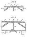
- Fig. 2shows a state in which the friction stir welding has been completed.
- Fig. 2shows the joining (welding) region W at an upper side of Fig. 1 .
- the joining region at a lower sideis symmetrical with the upper side joining region.
- the dent Kis caused, directed toward an inner side of the hollow frame member.
- the thick parts 56T and 66Tare remainders of the thickened parts 56 and 66.
- the thick parts 56T and 66Tinclude matters which are plastically deformed.
- a bottom face of the dent Kis positioned at the outer side portion 73a, outward from an outer face of the plates 51 and 61.
- an excessive part of the upper face joining region(a part extending outward from the faces of the general portions (non-thickened portions) of the plates 51 and 61)) is machined by, illustratively, a grinding machine, and it is performed to have the same plan face as the upper faces of the general portion of the plates 51 and 61. Since the upper face side is machined, it is possible to carry out easily the cutting working.
- the dent K and the thick parts 56T and 66Texist; however, when they exist at the inner face side of the car body, because they are covered by make-up plates it is unnecessary to machine them.
- Fig. 3shows a state in which the frame members 50 and 60 mounted on a bed stand 111 are joined through the upper side and the lower side, and next under a state in which they are mounted on the bed stand 111, the upper face side thick parts 56T and 66T have been machined.
- the end portions 56a and 66a of the thickened parts 56 and 66contact each other; however, in a case where a gap exists between the thickened parts, the base metal of the thickened parts 56 and 66 which has been fluidized under the friction stir welding is pushed into the gap. As a result, in a case of an existence of the gap, a default is not generated in the joining region.
- the height of the thickened part(H1 in Fig. 4 ) is 1 mm
- two members having a gap of 1 mm therebetweencan be joined without default.
- the two members to be joinedcan be in contact with each other, but need not be in contact; there can be a gap between the ends of the two members to be joined.
- the two members to be joinedcan be in contact or can have small gaps therebetween.
- the width W2 of the basis portions of the thickened parts 56 and 66is larger than a diameter D of the large diameter portion 71.
- the width W1 of the apex of the thickened parts 56 and 66is larger than a diameter d of the small diameter portion 72.
- the thickened parts 56 and 66 of the joining regionwhen joined, can have a trapezoid shape; in comparison with a case where the thickened parts 56 and 66 are extruded with four-sided shapes, in the present invention no excessive part exists.
- the present inventioncan dispense with a small amount of the hollow frame member, and further it is possible to lessen the manufacturing cost.
- the plate 54prevents the plates 51 and 61 from bending at the thickened parts 56 and 66, toward the inner side, due to the compressive force caused by the rotary bodies 70 and 70.
- the right-end shape structure of the hollow frame member 50may employ the left-end shape structure of the hollow frame member and also may employ the right-end shape structure of the hollow frame member 60.
- the shape structure of the hollow frame member 60can employ similar structure. In a word, it is preferable to joint the two hollow frame members.
- the rotary body 70is moved by detecting the abutting portion using an optical sensor. By detecting the slope faces 56c and 66c of the thickened parts 56 and 66, the position in the width direction of the rotary body 70 is determined. As shown in Fig. 7 , the slope faces 56n and 66nm for sensing can be provided at a part to which the thickened parts 56m and 66m are opposite. The slope face 56n (66n) can be provided respectively to both of the thickened parts 56m and 66m or can be provided to one of the thickened parts 56m and 66m.
- the two end faces 56a and 66a of the two joining regionsare parallel to the axis center of the rotary body 70; however, the two end faces 56a and 66a can be inclined against the axis center of the rotary body 70.
- the end face 56a of one member 50is inclined and against to this end face 56a the end face 66a of another member 60 can be overlapped at the upper side.
- the hollow frame members 50 and 60are mounted on the bed stands 111, 111 and fixed by a cramp 113.
- the abutting portions of the two hollow frame members 50 and 60are temporarily welded suitably.
- An upper side rotary body 70is hung down from a running body 121 which is run toward a width direction.
- the running body 121is moved along an upper portion frame of a gate type running body 122.
- the running body 122is run along a rail 123 which is arranged to both sides, along a longitudinal direction, of the hollow frame members 50 and 60.
- a lower side rotary body 70is provided on a running body 131 which is arranged between two seats 111 and 111.
- the running body 131is mounted on the running body 132 and is moved toward the width direction.
- the running body 132is run along the rail 133 and also along the longitudinal direction of the hollow frame members 50 and 60.
- the lower side rotary body 70is provided on a lower portion of the upper side rotary body 70.
- the running bodies 121 and 131also move the rotary bodies 70 and 70 in the vertical direction.
- rollers 124 and 134 for pressing the hollow frame members 50 and 60are provided on the running bodies 121 and 131.
- the rollers 124 and 134are arranged at a front portion of the rotary bodies 70 and 70 and on both sides of the thickened parts 56 and 66.
- the rollers 124 and 134are provided with plural rows along the running direction as occasion demands. Rollers can be added in front of and to the rear of the rotary body 70.
- the running bodies 121 and 131have a sensor (not shown in the figure) which can detect the position to be joined.
- the running bodies 121 and 131are moved in the width direction by the sensor.
- the slope faces 56c, 56c and 66c, 66care found and a center to be joined is detected.
- the hollow frame members 50 and 60After the joining of the upper face and the lower face of the hollow frame members 50 and 60 using the rotary bodies 70 and 70, and under a state in which the hollow frame members 50 and 60 are mounted on the bed stands 111 and 111, the hollow frame members 50 and 60 are finished smoothly by machining off the thick parts of the upper face.
- the thick partis machined leaving a little using the machine, and after that the remaining thick part is machined by manual working, it is possible to shorten the cutting working.
- the rotary body 70leaves a rear portion of running body 121 unoccupied, and the cutting tool is provided on the running body 121. And in a case where the rotary body 70 is rotated, the cutting tool carries out the cutting working.
- an end milling machine 126is provided on the upper face side running body 121.
- the end milling machine 126cuts off the thick parts 56T and 66T.
- a lower end of the end milling machine 126is positioned at an upper portion a little from the upper faces of the upper face plates 51 and 61 of the hollow frame members 50 and 60.
- a diameter of the end milling machine 126is sufficiently larger than the widths of the thick parts 56T and 66T which are positioned at the above-stated position.
- the rollers 124 and 134push down a vicinity of the end milling machine 126 from an upper portion and a lower portion and therefore a cutting amount by the end milling machine 126 is made uniformly.
- a pair of the hollow frame membershave respectively the thickened parts at the end portions; as shown in Fig. 8D , it is possible to constitute a case, not within the present invention, where only one of the hollow frame members has a thickened part.
- a metal of the thickened part 66is moved at a clearance between the hollow frame members 50 and 60 and an upper face of the plate of the hollow frame member 50.
- the thickened partis formed at the upper face plate 61, and in another hollow frame member 50 the lower face 52 has the thickened part.
- the frame membere.g., an extruded frame member
- the frame memberis a hollow frame member.
- Fig. 9shows an example of a joint structure, not within the invention, which has the thickened parts 34 and 35 at the end portions of the plate-shape extruded frame members 31 and 32, and the frame members 31 and 32 are joined by abutting the thick parts 34 and 35 to each other and friction stir welding.
- the extruded frame members 31 and 32are arranged on backing tools (bed stands) 36.
- backing tools 36are made of materials harder than the materials of the extruded frame members 31 and 32.
- the dent K and the thick partsare removed smoothly using the grinding machine, etc.
- the roller 124, etc., of the joining apparatusis similar to those of the above-stated embodiments.
- a structure, not within the present invention, shown from Fig. 12 to Fig. 14shows a case where one face of each of the frame members 37 and 38 has plural ribs 39; and at an opposed face to the face having the ribs 39 the extruded frame members 37 and 38, having the thickened parts 34b and 35b, are joined by friction stir welding.
- the bed stand 36Bmounts the lower ends of the ribs 39 and the lower faces of the thickened parts 34 and 35. The friction stir welding is performed similarly to the above-stated embodiments.
- a structure, not within the present invention, shown from Fig. 15 to Fig. 16shows a case where the extruded frame members 37c and 38c, having the thickened parts 34b and 35b, are provided at a side of the ribs 39. With this structure, a side of a bed stand 36C becomes flat.
- the joining region Wis a good joining region and a predetermined thickness thereof can be obtained.
- extruded frame members 150 and 150which extend in (have their lengths extending in) the same direction, are joined to each other, and the extruded frame members 160 and 160, which extend in (have their lengths extending in) the same direction, are joined to each other, by providing the thickened parts, similarly to the above-stated embodiments.
- FIG. 18shows a condition before the friction stir welding.
- the extruded frame members 150 and 160have a rib 153 and a rib 163 at one side of the plates.
- the extruded frame members 150 and 160are not the hollow frame members.
- the extruded frame members 150 and 160mount the plate 151 and the plate 161 on a bed stand 36C.
- the ribs 153 and 163direct toward the upper portions.
- the sides of the ribs 153 and 163are the inner side of the car, and the sides of the plates 151 and 161 are the outer side of the car.
- the end portion of the extruded frame member 150is extruded to a side of the rib 153 and constitutes a thickened part 156.
- the thickened part 156is extruded further toward the extruded frame member 160 to be welded and constitutes an extruded part 157.
- the extruded part 157is overlapped with an inner side of the plate 161 of the extruded frame member 160 (the side of the rib 163).
- the rib 163 of the part of the extruded part 157is cut off and removed.
- an extruded amount L2 of the extruded part 157is the same as a width L1 of the thickened part 156. Namely, the extruded part 157 corresponds to the thickened part 156.
- a tip portion of the extruded part 157has an oblique side surface similarly to that of the thickened part 156.
- the plate 161 at the vicinity of the extruded part 157can be pressed down, and a good welding can be obtained.
- a triangular-shaped groove 158is provided at an outer face of the thickened part 156 which is positioned between the end portion 150b of the extruded frame member 150 and the end portion 160b of the extruded frame member 160.
- This groove 158works a role of a positional mark for determining initially the position of the rotary body 70.
- This groove 158further works a role of a mark for the sensor.
- Fig. 20shows a case where the thickened part 156 and the extruded part 157 are not provided at the side of the rib 153.
- the ribs 153 and 163are mounted on a bed stand 36B.
- the thickened part 156, the extruded part 157 and the plates 151 and 161 surrounding these partsare mounted on a bed stand which projects toward an upper portion from the stand 36B.
- the rib 163 at the vicinity of the end portion of the extruded frame member 160is cut off.
- the thickened part 156 and the extruded part 157 of the extruded frame member 150are positioned at the side of the plate 151 (the outer face side of the car).
- the extruded part toward the adjacent membercan be adapted to the hollow extruded frame member, etc.
- the provision of the extruded partcan be adapted to joining two extruded frame members which are not orthogonal, namely, to the welding of two parallel members.
Landscapes
- Engineering & Computer Science (AREA)
- Mechanical Engineering (AREA)
- Physics & Mathematics (AREA)
- Optics & Photonics (AREA)
- Electromagnetism (AREA)
- Pressure Welding/Diffusion-Bonding (AREA)
Description
- The present invention relates to a combination of first and second extruded frame members to be joined to each other by friction stir welding. The invention is suitable for use in joining of members of various materials, including, for example, aluminum alloy members, etc.
- Friction stir welding is a method in which by rotating a round-shaped rod (a rotary body) inserted in a joining region between two members (e.g., but not limiting, two metal bodies, such as two A1 bodies), and further by moving the rotary body along a joining line, the two bodies at the joining region are heated, and material thereof softened and plastically fluidized and thus the two bodies are solid-phase joined, e.g., are welded together at the joining region.
- Conventionally, the rotary body comprises a small diameter portion which is inserted in the joining region and a large diameter portion which is positioned outside the joining region. The small diameter portion and the large diameter portion are positioned on the same axis. A side of the large diameter portion is rotated, whereby both the large and small diameter portions are rotated. A boundary portion between the small diameter portion and the large diameter portion can be inserted a little into the joining region. A joining according to the friction stir welding method can be applied to an abutting portion and an overlapping portion.
- The above-stated prior technique is disclosed, for example, in Japanese patent announcement laid-open publication No.
Hei 7-505090 EP 0615480 B1 );Dawes, "An Introduction to Friction stir Welding and Its Development", in Welding & Metal Fabrication (January 1995), pages 13, 14 and 16; andEP-A-0797043 . - This prior technique is also described in the article byT. Shinoda and Y. Kondoh, "324 Butt Welding of Plate Using Friction stir Welding; Method Study of Friction Stir Welding", Welding Associate Japan Lecture Meeting Outline, No. 56 (April 1995), pages 208 and 209. This article discloses a rotary body (rotary tool) made of stainless steel, members to be welded (joined) made of pure aluminum (A1100), and the members to be welded having a plate thickness of 6 mm. The rotary body has a large diameter portion with a diameter of 20 mm, and a small diameter portion (cylindrical) with a diameter of 6 mm and a length (axially) of 5 mm. In operation, the rotary body rotates at 1000-2500 rpm, and moves along the two members to be welded at a speed of 1.0-8.0 mm/s.
- In the article described in the foregoing paragraph, the members to be joined are made of aluminum. Alloys of aluminum are also suitable for welding by friction stir welding; other metals studied for welding by friction stir welding include copper, titanium and stainless steel.
EP 0615480 B1 , referred to previously herein, discloses friction stir welding of plastic (e.g., thermoplastic) materials. All of these materials can be welded by the process of the present invention. - According to various experiments with the friction stir welding, a part of an upper face of a joining region of two members is machined as chips, by a rotation of the large diameter portion of the rotary body, and a dent is caused in the upper face of the joining region. At both sides of the dent, a thickened part is caused according to plastic deformation of the members.
- It is easy to delete the thickened part; however, correcting for the dent needs a putty working, etc., and as a result a high manufacturing cost is caused.
- Further, in a case where before the joining working a gap exists between end faces of the abutting faces of the two members, a default such as a dent, etc., is generated at the joining region. As a result, a lowering in strength is caused, and particularly in a large-scale construction it invites a problem. The larger the members, the more a management in the above-stated gap becomes difficult (i.e., the more the gap occurs); accordingly, the dent becomes large, and, moreover, a default is generated easily.
- In a case where the joining region is covered by another member, for example, the existence of the dent is not as much a problem, and there is no problem except for the strength problem (which, of course, can be a serious problem itself). However, in a side face, etc., of a car body of cars (e.g., railroad cars), it is necessary to remove the dent from a viewpoint of an outward appearance. Further, even in a case where the dent is not visible, the dent becomes a problem from an aspect of the performance (e.g., strength of the weld).
- An object of the present invention is to prevent generation of a dent in a joining region when joining two members (e.g., but not limited to, two metal members, such as of aluminum alloy) by a friction stir welding method.
- The invention provides a combination of first and second extruded frame members to be joined to each other by friction stir welding, as set out in claim 1.
- In the friction stir welding of such members, the rotary body typically has large and small diameter portions, e.g., made of a material or materials harder than the material of the members to be welded, the small diameter portion first being inserted in the joining region of the members to be joined, during the joining. The members to be joined are positioned adjacent each other, with the thickened portions positioned adjacent each other in the joining (joint-forming) region. The rotary body is then caused to enter between the two members, in the joining region, with the small diameter portion of the rotary body being inserted into the joint-forming region of the two members and the large diameter portion of the rotary body extending into the thickened portion (but not below the thickened portion). The rotary body is then moved along the members to be welded, in the joining region, with the rotary body inserted as described in the previous sentence to perform the friction stir welding. Due to provision of the thickened portions, at the joint-forming region, a dent (depressed region) at the weld region, in the joined members, can be avoided. By positioning the rotary body such that the large-diameter portion thereof is inserted into the thickened portion (overlaps with the thickened portion), an excellent weld is achieved, while avoiding a dent in the welded joint. Advantageously, the large-diameter portion of the rotary body does not extend below the protruding portion of the thickened portion, while moving the rotary body to perform the friction stir welding.
- The thickened portion of the member is an integral part of the member, and, e.g., extends to the edge (of the member) which is to be positioned adjacent another member to which the member is to be welded.
- Preferably, the thickened portion has a side, furthest from the weld location, which, in cross section, is sloped (e.g., makes an acute angle of less than 90° with the plane of the surface of the member (other than the protruding portion); see θ in
Fig.4 ). Desirably, this side furthest from the weld location makes an angle of 15°-60°, preferably 30°, with the plane of the surface of the member. Figure 1 is a longitudinal cross-sectional view showing a part of one embodiment according to the present invention.Figure 2 is a longitudinal cross-sectional view showing a state after a friction stir welding of the structure ofFig. 1 .Figure 3 is a longitudinal cross-sectional view showing a state in which after a friction stir welding of the structure ofFig. 1 has been carried out, a finishing process is carried out on one side.Figure 4 is a view for explaining dimensions.Figure 5 is a perspective view showing a car body of a railway car.Figure 6 is a longitudinal cross-sectional view showing a part of another embodiment according to the present invention.Figure 7 is a lateral cross-sectional view showing a joining region of another embodiment according to the present invention.Figure 8A is a longitudinal cross-sectional view showing a joining apparatus which may be used in methods described herein.Figure 8B is a longitudinal cross-sectional view of components in a method described herein.Figure 8C is a left-side view ofFigure 8B .Figure 8D is a longitudinal cross-sectional view of a part of a further construction not within the present invention.Figure 9 is a longitudinal cross-sectional view showing a joining region of another construction not within the present invention.Figure 10 is a longitudinal cross-sectional view showing a welded structure after a friction stir welding of the structure ofFig. 9 .Figure 11 is a longitudinal cross-sectional view showing the resulting structure after a thicker part of the structure inFig. 10 is finished smoothly.Figure 12 is a longitudinal cross-sectional view of a joining region of another construction not within the present invention.Figure 13 is a longitudinal cross-sectional view showing the resulting structure after a friction stir welding of the structure shown inFig. 12 .Figure 14 is a longitudinal cross-sectional view showing the resulting structure after a thicker part of the structure shown inFig. 13 is finished smoothly.Figure 15 is a longitudinal cross-sectional view of a joining region of another construction not within the present invention.Figure 16 is a longitudinal cross-sectional view showing the resulting structure after a friction stir welding of the structure shown inFig. 15 .Figure 17 is a front view of a side structure body of a railway vehicle.Figure 18 is a cross-sectional view taken along the line XVIII-XVIII ofFigure 17 .Figure 19 is a right-side view ofFigure 18 .Figure 20 is a longitudinal cross-sectional view of a part of a further construction not within the present invention.- One embodiment of the present invention, which is an application of the present invention for a car body of railway cars, will be explained referring to
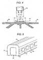
Figs. 1-5 . - In
Fig. 5 , a car body of a railway car is comprised of a sideconstructive body 41, a roofconstructive body 42, a floorconstructive body 43, and aconstructive body 44 of an end portion at a longitudinal direction. The sideconstructive body 41 is constituted by arranging plural hollow extruded frame members (50, 60) and by joining contacting portions thereof. The joining is carried out as shown inFig. 1 . - Each of the roof
constructive body 42 and the floorconstructive body 43 is constituted similarly. Connections between the sideconstructive body 42 and the roofconstructive body 41 and the floorconstructive body 43 are carried out using an MIG (metal electrode inert gas) welding, etc. Fig. 1 shows a joint portion of a hollow frame member which constitutes the sideconstructive body 41. Thehollow frame members hollow frame members plates diagonal plates plates - An end portion of one
hollow frame member 50 is entered into an end portion of anotherhollow frame member 60. Avertical plate 54 for joining theplate 51 and theplate 52 is provided at a vicinity of the end portion of thehollow frame member 50. Areference numeral 54 is an extruded member for supporting the end portion of thehollow frame member 50. - On an extension line of a center of the thickness direction (in
Fig. 1 , a right and left direction) of theplate 54, the end portions of the members to be joined have thickened parts (protruding portions) of the twohollow frame members hollow frame members - The
plates Fig. 2 , for example) and are extruded and formed thick to form the thickened parts at a side of a front face (an outside in the thickness direction of the hollow frame member, or a side facing the tool for carrying out the joining working (welding), namely, a side facing therotary body 70 which is a tool for friction stir welding. - The thickened
parts plates parts parts Fig. 1 , although the present invention is not limited to the alignedparts - The
rotary bodies rotary body 70 has a small diameter round-shape rod 72 (a smaller diameter portion) at a tip end of a large diameter round-shape rod (a larger diameter portion) 71 which acts as a base portion. Thelarge diameter portion 71 and thesmall diameter portion 72 are disposed on the same axis. - The lower
side rotary body 70 is positioned downwardly substantially vertically below the upper siderotary body 70. Therotary bodies hollow frame members rotary body 70 is harder than the materials of thehollow frame members - By rotating the two
rotary bodies small diameter portion 72 is inserted into the joining region of thehollow frame members rotary bodies hollow frame members rotary bodies - During the friction stir welding, at a side of the upper side
rotary body 70, a boundary portion 73 (a substantially flat shape portion), between thelarge diameter portion 71 and thesmall diameter portion 72 of therotary body 70, is positioned spaced upward a little, at anupper portion 73a (at a side of a face of an apex of the thickenedparts parts 56 and 66), from an extension of an upper face of the general portion (the non-projecting portion) of theplates large diameter portion 71 of the upper siderotary body 70 extends below the upper face of the thickened part (e.g., is inserted into the thickened part), it does not extend below the level of the non-projecting portion of theplates - At a side of the lower
side rotary body 70, theboundary portion 73 between thelarge diameter portion 71 and thesmall diameter portion 72 is positioned a little below an extension of a lower face of the general portion (the non-projecting portion) of theplates 52 and 62 (between the face side of the apex of the thickenedparts parts 56 and 66). - Namely, the
boundary portion 73 between thelarge diameter portion 71 and thesmall diameter portion 72 is positioned at an outer side of the extension line of the face of the outer side of the non-projecting portion of theplates parts Fig. 1 , theline 73a indicates a position of theboundary portion 73. In other words, the large diameter portion is inserted to a position (with respect to the upper rotary body) below the apex of the thickened part but not below the extension line of the non-projecting portion of theplates - In a case of performing the welding, the
frame members rotary body 70 is a center of the joining region; namely, such center is a center of the thickness of theplate 54. - In
Fig. 4 , a relationship about the dimensions of the respective portions will be explained. A width W1 of an apex of the two thickenedportions 56 and 66 (twowelding portions 56 and 66), in a case where the two thickenedportions 56 and 66 (twowelding portions 56 and 66) are abutted, is larger than a diameter d of thesmall diameter portion 72 but is smaller than a diameter D of thelarge diameter portion 71. - A width W2 of the basis portion of the two thickened
portions 56 and 66 (twowelding portions 56 and 66) is larger than the diameter D of thelarge diameter portion 71. A height H1 of the two thickenedportions 56 and 66 (twowelding portions 56 and 66) is longer than a length of thesmall diameter portion 72. - When a lower end of the
large diameter portion 71 is positioned at theposition 73a of the two thickenedportions 56 and 66 (twowelding portions 56 and 66), a tip end of thesmall diameter portion 72 reaches themember 55 or is positioned in the vicinity of themember 55. Fig. 2 shows a state in which the friction stir welding has been completed.Fig. 2 shows the joining (welding) region W at an upper side ofFig. 1 . The joining region at a lower side is symmetrical with the upper side joining region. At a side of an outer face of the joining region W, the dent K is caused, directed toward an inner side of the hollow frame member. At both sides of the dent K there arethick parts - The
thick parts parts thick parts outer side portion 73a, outward from an outer face of theplates - In a case where the upper side face of
Fig. 1 is the outer face side of the car body of a railway car, an excessive part of the upper face joining region (a part extending outward from the faces of the general portions (non-thickened portions) of theplates 51 and 61)) is machined by, illustratively, a grinding machine, and it is performed to have the same plan face as the upper faces of the general portion of theplates - At the lower face side, similarly to the above, the dent K and the
thick parts Fig. 3 shows a state in which theframe members bed stand 111 are joined through the upper side and the lower side, and next under a state in which they are mounted on thebed stand 111, the upper face sidethick parts - According to the above structure, an occurrence of the dent K extending to a level below the level of the faces of the general portions (non-thickened portions) of the
plates - Further, in the above-stated embodiment, the
end portions parts parts - Concretely, when the height of the thickened part (H1 in
Fig. 4 ) is 1 mm, two members having a gap of 1 mm therebetween can be joined without default. Further, it is possible to position the dent K outside of an extension line of the outer face of theplates plates - As seen in the foregoing, the two members to be joined can be in contact with each other, but need not be in contact; there can be a gap between the ends of the two members to be joined. Throughout the present disclosure, where it is described that the two members to be joined are adjacent (abutting) each other, the two members can be in contact or can have small gaps therebetween.
- Illustratively, the width W2 of the basis portions of the thickened
parts large diameter portion 71. The width W1 of the apex of the thickenedparts small diameter portion 72. When the center of therotary body 70 is shifted from the center of the thickenedparts - Further, the thickened
parts parts - Further, it is possible to lessen the machining amount by the grinding machine, since, e.g., only remaining portions of the thickened parts need be machined. Further, as shown in
Fig. 6 , aftersides parts plates portions - The
plate 54 prevents theplates parts rotary bodies - In
Fig. 1 , the right-end shape structure of thehollow frame member 50 may employ the left-end shape structure of the hollow frame member and also may employ the right-end shape structure of thehollow frame member 60. The shape structure of thehollow frame member 60 can employ similar structure. In a word, it is preferable to joint the two hollow frame members. - The
rotary body 70 is moved by detecting the abutting portion using an optical sensor. By detecting the slope faces 56c and 66c of the thickenedparts rotary body 70 is determined. As shown inFig. 7 , the slope faces 56n and 66nm for sensing can be provided at a part to which the thickenedparts slope face 56n (66n) can be provided respectively to both of the thickenedparts parts - In each of the above-stated embodiments, the two end faces 56a and 66a of the two joining regions are parallel to the axis center of the
rotary body 70; however, the two end faces 56a and 66a can be inclined against the axis center of therotary body 70. For example, theend face 56a of onemember 50 is inclined and against to thisend face 56a theend face 66a of anothermember 60 can be overlapped at the upper side. - According to this structure, even when the gap between the two end faces is large, according to the rotation of the
rotary body 70 it is possible to prevent the outflow of the fluidized metal from the extrudedmember 55. This structure is suitable to the connection of mutual pipes. - A joining apparatus will be explained referring to
Fig. 8A . Thehollow frame members cramp 113. The abutting portions of the twohollow frame members - An upper side
rotary body 70 is hung down from a runningbody 121 which is run toward a width direction. The runningbody 121 is moved along an upper portion frame of a gatetype running body 122. The runningbody 122 is run along arail 123 which is arranged to both sides, along a longitudinal direction, of thehollow frame members - A lower
side rotary body 70 is provided on a runningbody 131 which is arranged between twoseats body 131 is mounted on the runningbody 132 and is moved toward the width direction. - The running
body 132 is run along therail 133 and also along the longitudinal direction of thehollow frame members side rotary body 70 is provided on a lower portion of the upper siderotary body 70. The runningbodies rotary bodies Plural rollers hollow frame members bodies rollers rotary bodies parts rollers rotary body 70.- The running
bodies bodies - After the joining of the upper face and the lower face of the
hollow frame members rotary bodies hollow frame members hollow frame members - When the machining grinding working is carried out by a manual working, it can be finished more smoothly. For this reason, it is possible to put on at the upper face the thick part for carrying out the machining working.
- Further, first of all, since the thick part is machined leaving a little using the machine, and after that the remaining thick part is machined by manual working, it is possible to shorten the cutting working. In this case the
rotary body 70 leaves a rear portion of runningbody 121 unoccupied, and the cutting tool is provided on the runningbody 121. And in a case where therotary body 70 is rotated, the cutting tool carries out the cutting working. - For example, as shown in
Figs. 8B and 8C , to the rear of therotary body 70 of the upper face side, anend milling machine 126 is provided on the upper faceside running body 121. Theend milling machine 126 cuts off thethick parts end milling machine 126 is positioned at an upper portion a little from the upper faces of theupper face plates hollow frame members end milling machine 126 is sufficiently larger than the widths of thethick parts rollers end milling machine 126 from an upper portion and a lower portion and therefore a cutting amount by theend milling machine 126 is made uniformly. - In the above-stated embodiments, a pair of the hollow frame members have respectively the thickened parts at the end portions; as shown in
Fig. 8D , it is possible to constitute a case, not within the present invention, where only one of the hollow frame members has a thickened part. A metal of the thickenedpart 66 is moved at a clearance between thehollow frame members hollow frame member 50. Further, similarly to the above, in onehollow frame member 60 the thickened part is formed at theupper face plate 61, and in anotherhollow frame member 50 thelower face 52 has the thickened part. - In the above-stated embodiments, the frame member (e.g., an extruded frame member) is a hollow frame member.
Fig. 9 shows an example of a joint structure, not within the invention, which has the thickenedparts frame members frame members thick parts frame members tools 36 are made of materials harder than the materials of the extrudedframe members - Along to the abutting face of this joint, since the
rotary body 70 is rotated and moved, then the joining region W shown inFig. 10 can be obtained. The conditions for therotary body 70 against the thickenedparts - Next, as shown in
Fig. 11 , the dent K and the thick parts are removed smoothly using the grinding machine, etc. Theroller 124, etc., of the joining apparatus is similar to those of the above-stated embodiments. - Further, in a case where the extruded frame member, etc., has only one joining region, in the arrangement shown in
Fig. 8A , in place of the lowerside rotary body 70, a roll for supporting the extruded frame member can be arranged. With this structure, it is unnecessary to support a whole face of theframe members - A structure, not within the present invention, shown from
Fig. 12 to Fig. 14 shows a case where one face of each of theframe members plural ribs 39; and at an opposed face to the face having theribs 39 the extrudedframe members parts ribs 39 and the lower faces of the thickenedparts - A structure, not within the present invention, shown from
Fig. 15 to Fig. 16 shows a case where the extrudedframe members parts ribs 39. With this structure, a side of abed stand 36C becomes flat. - As a result, in a case where at the opposite side of the ribs 39 a little unevenness is permitted, it is possible to delete the finishing process for making the joining smooth, so that the joined structure can be manufactured at a low cost. The joining region W is a good joining region and a predetermined thickness thereof can be obtained.
- A structure, not within the invention, shown from
Fig. 17 to Fig. 19 will be explained. InFig. 17 , aside structure body 416 of a railway vehicle is comprised of pluralextruded frame members frame members exit port 171 and awindow 172, and between thewindow 172 and thewindow 172, extend in a longitudinal direction inFig. 17 (that is, have their length extending in this longitudinal direction). Each of the extrudedframe members window 172 and at the upper portions of thewindow 172 extend in a lateral direction inFig. 17 (that is, have their length extending in this lateral direction). Namely, the extrudedframe members 150 and the extrudedframe members 160 extend in directions (that is, have their lengths) orthogonal to each other. - The extruded
frame members frame members - An intersecting portion of the directions that the
frame members Fig. 18. Fig. 18 shows a condition before the friction stir welding. The extrudedframe members rib 153 and arib 163 at one side of the plates. The extrudedframe members frame members plate 151 and theplate 161 on abed stand 36C. Theribs ribs plates - The end portion of the extruded
frame member 150 is extruded to a side of therib 153 and constitutes a thickenedpart 156. The thickenedpart 156 is extruded further toward the extrudedframe member 160 to be welded and constitutes anextruded part 157. Theextruded part 157 is overlapped with an inner side of theplate 161 of the extruded frame member 160 (the side of the rib 163). Therib 163 of the part of theextruded part 157 is cut off and removed. Illustratively, an extruded amount L2 of theextruded part 157 is the same as a width L1 of the thickenedpart 156. Namely, theextruded part 157 corresponds to the thickenedpart 156. A tip portion of theextruded part 157 has an oblique side surface similarly to that of the thickenedpart 156. - By inserting the
rotary body 70 from an upper portion, when the friction stir welding is carried out, since theextruded part 157 exists overlying aclearance 150c between theend portions frame members extruded part 157, etc., is supplied to theclearance 150c. Further, the metal is supplied also to the upper portion of the extrudedframe member 160. As a result, in a case of the comparison with structure which did not have the thickenedpart 156 and theextruded part 157, and further in comparison with structure which did not have only theextruded part 157, in this case a good welding can be obtained. - Since by cutting off the
rib 163 of the extrudedframe member 160 and the extrudedframe member 160 is overlapped by theextruded part 157, theplate 161 at the vicinity of theextruded part 157 can be pressed down, and a good welding can be obtained. - A triangular-shaped
groove 158 is provided at an outer face of the thickenedpart 156 which is positioned between theend portion 150b of the extrudedframe member 150 and theend portion 160b of the extrudedframe member 160. Thisgroove 158 works a role of a positional mark for determining initially the position of therotary body 70. Thisgroove 158 further works a role of a mark for the sensor. Fig. 20 shows a case where the thickenedpart 156 and theextruded part 157 are not provided at the side of therib 153. Theribs bed stand 36B. The thickenedpart 156, theextruded part 157 and theplates stand 36B. Therib 163 at the vicinity of the end portion of the extrudedframe member 160 is cut off. The thickenedpart 156 and theextruded part 157 of the extrudedframe member 150 are positioned at the side of the plate 151 (the outer face side of the car).- In a case of the welding of the extruded frame members in which the extruded direction is orthogonal, it is possible to use structure having only the thickened
part 156 and not theextruded part 157. Further, the provision of the extruded part toward the adjacent member can be adapted to the hollow extruded frame member, etc. Further, the provision of the extruded part can be adapted to joining two extruded frame members which are not orthogonal, namely, to the welding of two parallel members. - Through use of the present invention, dents extending below the surfaces of the joined members can be avoided. Therefore, finishing of the joined members, to provide a smooth surface extending across the joint between the joined members, can be simplified.
- Furthermore, even when there is a gap (or gaps) between the members to be joined by the friction stir welding and these gaps are large, dents extending below the surfaces of the joined members can be avoided, simplifying finishing work in providing a smooth surface extending across the joint.
Claims (2)
- A combination of first and second extruded frame members (50, 60) to be joined to each other by friction stir welding, each of said frame members (50, 60) having a thickness direction and a width direction and comprising first and second parallel spaced plates (51, 52, 61, 62) extending in said width direction and further plates (53, 54, 63) connected between the first and second plates;
each of said first and second plates (51, 52, 61, 62) of each said frame member thus having an inside face facing the other thereof in the thickness direction and an outside face facing away from the other thereof in the thickness direction, and each of said first and second plates (51, 52, 61, 62) of each said frame member having an end in said width direction at which it is to be joined by the friction stir welding to the respective one of the first and second plates of the other of the frame members;
each of said first and second plates (51, 52, 61, 62) of each said frame member having at said end thereof a thickened portion (56, 66) which protrudes from said outside face of the plate in the thickness direction away from the other of the plates of the frame member, each said thickened portion (56, 66) having, at its side facing away from said end of the respective plate, a surface (56c, 66c) inclined to the respective said outside face;
said further plates of said first frame member (50) being diagonal plates (53) arranged with a truss shape and a vertical plate (54) which connects said thickened portions (56) of said first and second plates (51, 52) of the first frame member; said further plates of said second frame member (60) being diagonal plates (63) arranged with a truss shape;
said first frame member (50) having, adjacent each of said thickened portions (56) of said first frame member, an extruded part (55) which extends outwardly from said vertical plate (54) in said thickness direction so that, when said first and second members are arranged for welding with said thickness directions thereof aligned with each other and said thickened parts of the respective first plates are next to each other and the thickened parts of the respective second plates are next to each other, said extruded parts (55) overlap the first and second plates (61, 62) of the second frame member (60) at the inside faces thereof. - A combination according to claim 1, wherein the angle of said inclined surface (56c, 66c) with the plane of the respective outside face of the frame member is 15-60°C.
Applications Claiming Priority (3)
| Application Number | Priority Date | Filing Date | Title |
|---|---|---|---|
| JP19675997 | 1997-07-23 | ||
| JP19675997 | 1997-07-23 | ||
| EP98301177AEP0893189B1 (en) | 1997-07-23 | 1998-02-18 | Friction stir welding method. |
Related Parent Applications (2)
| Application Number | Title | Priority Date | Filing Date |
|---|---|---|---|
| EP98301177.6Division | 1998-02-18 | ||
| EP98301177ADivisionEP0893189B1 (en) | 1997-07-23 | 1998-02-18 | Friction stir welding method. |
Publications (2)
| Publication Number | Publication Date |
|---|---|
| EP1462205A1 EP1462205A1 (en) | 2004-09-29 |
| EP1462205B1true EP1462205B1 (en) | 2011-04-06 |
Family
ID=16363157
Family Applications (12)
| Application Number | Title | Priority Date | Filing Date |
|---|---|---|---|
| EP04011030AExpired - LifetimeEP1462205B1 (en) | 1997-07-23 | 1998-02-18 | A combination of first and a second extruded frame members to be joined to each other by friction stir welding |
| EP04002653AExpired - LifetimeEP1442821B1 (en) | 1997-07-23 | 1998-02-18 | A joined structure of two members joined by a friction stir welded welding portion |
| EP04002659AExpired - LifetimeEP1442825B9 (en) | 1997-07-23 | 1998-02-18 | Friction stir welding method |
| EP04002662AExpired - LifetimeEP1442828B1 (en) | 1997-07-23 | 1998-02-18 | Friction stir welding method |
| EP04002655AExpired - LifetimeEP1442822B1 (en) | 1997-07-23 | 1998-02-18 | Friction stir welding method, frame members used therein, and product thereby |
| EP04002654AExpired - LifetimeEP1442867B1 (en) | 1997-07-23 | 1998-02-18 | Friction stir welding method, frame members used therein, and product formed thereby |
| EP04002660AExpired - LifetimeEP1442826B1 (en) | 1997-07-23 | 1998-02-18 | Friction stir welded joint structure. |
| EP04002661AExpired - LifetimeEP1442827B1 (en) | 1997-07-23 | 1998-02-18 | Friction stir welded product |
| EP98301177AExpired - LifetimeEP0893189B1 (en) | 1997-07-23 | 1998-02-18 | Friction stir welding method. |
| EP04002657AExpired - LifetimeEP1442823B1 (en) | 1997-07-23 | 1998-02-18 | Friction stir welding method, frame members used therein, and product formed thereby |
| EP04002658AExpired - LifetimeEP1442824B1 (en) | 1997-07-23 | 1998-02-18 | Friction stir welding method, frame members used therein, and product formed thereby |
| EP04002656AExpired - LifetimeEP1442868B1 (en) | 1997-07-23 | 1998-02-18 | Friction stir welding method, frame members used therein, and product formed thereby |
Family Applications After (11)
| Application Number | Title | Priority Date | Filing Date |
|---|---|---|---|
| EP04002653AExpired - LifetimeEP1442821B1 (en) | 1997-07-23 | 1998-02-18 | A joined structure of two members joined by a friction stir welded welding portion |
| EP04002659AExpired - LifetimeEP1442825B9 (en) | 1997-07-23 | 1998-02-18 | Friction stir welding method |
| EP04002662AExpired - LifetimeEP1442828B1 (en) | 1997-07-23 | 1998-02-18 | Friction stir welding method |
| EP04002655AExpired - LifetimeEP1442822B1 (en) | 1997-07-23 | 1998-02-18 | Friction stir welding method, frame members used therein, and product thereby |
| EP04002654AExpired - LifetimeEP1442867B1 (en) | 1997-07-23 | 1998-02-18 | Friction stir welding method, frame members used therein, and product formed thereby |
| EP04002660AExpired - LifetimeEP1442826B1 (en) | 1997-07-23 | 1998-02-18 | Friction stir welded joint structure. |
| EP04002661AExpired - LifetimeEP1442827B1 (en) | 1997-07-23 | 1998-02-18 | Friction stir welded product |
| EP98301177AExpired - LifetimeEP0893189B1 (en) | 1997-07-23 | 1998-02-18 | Friction stir welding method. |
| EP04002657AExpired - LifetimeEP1442823B1 (en) | 1997-07-23 | 1998-02-18 | Friction stir welding method, frame members used therein, and product formed thereby |
| EP04002658AExpired - LifetimeEP1442824B1 (en) | 1997-07-23 | 1998-02-18 | Friction stir welding method, frame members used therein, and product formed thereby |
| EP04002656AExpired - LifetimeEP1442868B1 (en) | 1997-07-23 | 1998-02-18 | Friction stir welding method, frame members used therein, and product formed thereby |
Country Status (6)
| Country | Link |
|---|---|
| US (14) | US6050474A (en) |
| EP (12) | EP1462205B1 (en) |
| JP (5) | JP3070735B2 (en) |
| KR (11) | KR100428535B1 (en) |
| CN (15) | CN1292870C (en) |
| DE (12) | DE69840950D1 (en) |
Families Citing this family (260)
| Publication number | Priority date | Publication date | Assignee | Title |
|---|---|---|---|---|
| NO954273D0 (en)* | 1995-10-26 | 1995-10-26 | Norsk Hydro As | Wheels Wheel |
| CN1165403C (en)* | 1996-03-19 | 2004-09-08 | 株式会社日立制作所 | Components for friction welding |
| JP4406092B2 (en)* | 1997-05-16 | 2010-01-27 | エサブ アクチボラゲット | Welding assembly for rotary friction welding |
| GB9713209D0 (en)* | 1997-06-20 | 1997-08-27 | British Aerospace | Friction welding metal components |
| JP3070735B2 (en)* | 1997-07-23 | 2000-07-31 | 株式会社日立製作所 | Friction stir welding method |
| JP3589863B2 (en)* | 1997-07-23 | 2004-11-17 | 株式会社日立製作所 | Structure and friction stir welding method |
| SE9704800D0 (en)* | 1997-12-19 | 1997-12-19 | Esab Ab | Device for welding |
| JP3333728B2 (en)* | 1997-12-25 | 2002-10-15 | 東海ゴム工業株式会社 | Bush mounting member and method of manufacturing the same |
| US6290117B1 (en)* | 1998-02-17 | 2001-09-18 | Hitachi, Ltd. | Friction stir welding method and friction stir welding apparatus |
| JP3420502B2 (en)* | 1998-06-16 | 2003-06-23 | 株式会社日立製作所 | Structure |
| US6745929B1 (en)* | 1998-06-16 | 2004-06-08 | Hitachi, Ltd. | Method of manufacturing structural body and structural body |
| JP4004150B2 (en)* | 1998-09-11 | 2007-11-07 | 本田技研工業株式会社 | Rear cushion bracket mounting structure |
| ES2281134T3 (en)* | 1998-09-28 | 2007-09-16 | Hitachi, Ltd. | BODYWORK. |
| AU733140B2 (en)* | 1998-09-29 | 2001-05-10 | Hitachi Limited | A friction stir welding method |
| US7748233B2 (en) | 1998-12-23 | 2010-07-06 | S.I.P. Technologies L.L.C. | Sanitized water dispenser |
| US7175054B2 (en)* | 1998-12-23 | 2007-02-13 | S.I.P. Technologies, Llc | Method and apparatus for disinfecting a refrigerated water cooler reservoir |
| US6247633B1 (en)* | 1999-03-02 | 2001-06-19 | Ford Global Technologies, Inc. | Fabricating low distortion lap weld construction |
| WO2000056497A1 (en)* | 1999-03-24 | 2000-09-28 | Framatome Anf Gmbh | Method and device for welding two work pieces |
| JP3459193B2 (en)* | 1999-05-26 | 2003-10-20 | 株式会社日立製作所 | Method of repairing friction stir welding and method of manufacturing railway vehicle |
| TW464576B (en)* | 1999-05-28 | 2001-11-21 | Hitachi Ltd | A structure body and a manufacturing method of a structure body |
| TW460346B (en)* | 1999-05-28 | 2001-10-21 | Hitachi Ltd | A manufacturing method of a structure body and a manufacturing apparatus of a structure body |
| JP3481501B2 (en)* | 1999-05-28 | 2003-12-22 | 株式会社日立製作所 | Structure and method of manufacturing the same |
| JP3868695B2 (en)* | 1999-05-28 | 2007-01-17 | 株式会社日立製作所 | Manufacturing method of structure |
| TW449519B (en) | 1999-05-31 | 2001-08-11 | Hitachi Ltd | A manufacturing method of a structure body |
| JP2000343245A (en)* | 1999-05-31 | 2000-12-12 | Hitachi Ltd | How to make a structure |
| AU7475200A (en)* | 1999-09-03 | 2001-04-10 | Lockheed Martin Corporation | Friction stir welding as a rivet replacement technology |
| JP3563003B2 (en)* | 1999-09-30 | 2004-09-08 | 株式会社日立製作所 | Friction stir welding method for structures |
| DE19957136C1 (en)* | 1999-11-18 | 2001-02-08 | Geesthacht Gkss Forschung | Friction welding appts has a projecting and rotating pin to act on the workpiece materials at the welding zone to follow the welding line and soften the materials to fuse together and bond sheet plates with complex shapes |
| JP3459210B2 (en)* | 1999-11-24 | 2003-10-20 | 株式会社日立製作所 | Friction stir welding method |
| US6722286B2 (en)* | 1999-12-14 | 2004-04-20 | Hitachi, Ltd. | Structure and railway car |
| JP3538357B2 (en)* | 2000-01-24 | 2004-06-14 | 株式会社日立製作所 | Friction stir welding method |
| JP3552978B2 (en)* | 2000-01-27 | 2004-08-11 | 株式会社日立製作所 | Hollow profile |
| US6299050B1 (en)* | 2000-02-24 | 2001-10-09 | Hitachi, Ltd. | Friction stir welding apparatus and method |
| JP3589930B2 (en)* | 2000-02-25 | 2004-11-17 | 株式会社日立製作所 | Friction stir welding method |
| US6237835B1 (en)* | 2000-02-29 | 2001-05-29 | The Boeing Company | Method and apparatus for backing up a friction stir weld joint |
| JP3575748B2 (en) | 2000-03-06 | 2004-10-13 | 株式会社日立製作所 | Friction stir welding method |
| US6367681B1 (en)* | 2000-04-04 | 2002-04-09 | The Boeing Company | Friction stir welding apparatus and method |
| JP2001293582A (en) | 2000-04-13 | 2001-10-23 | Nissan Motor Co Ltd | Aluminum links |
| JP3867475B2 (en)* | 2000-04-28 | 2007-01-10 | マツダ株式会社 | Method for processing metal members |
| JP3400409B2 (en)* | 2000-04-28 | 2003-04-28 | マツダ株式会社 | Joining method and joining device |
| MXPA02010936A (en) | 2000-05-08 | 2004-09-06 | Univ Brigham Young | Friction stir weldin of metal matrix composites, ferrous alloys, non ferrous alloys, and superalloys using a superabrasive tool. |
| JP3429475B2 (en)* | 2000-05-08 | 2003-07-22 | 川崎重工業株式会社 | Spot joining apparatus and spot joining method |
| JP3781099B2 (en)* | 2000-06-02 | 2006-05-31 | トヨタ自動車株式会社 | Hollow product, fluid processing system, and method for joining hollow members |
| JP3274453B2 (en)* | 2000-06-05 | 2002-04-15 | 川崎重工業株式会社 | Joint failure detection method in friction stir welding |
| JP4467723B2 (en)* | 2000-06-30 | 2010-05-26 | 昭和電工株式会社 | Friction stir welding method |
| US6352193B1 (en) | 2000-08-01 | 2002-03-05 | General Electric Company | Apparatus for joining electrically conductive materials |
| US6619533B1 (en)* | 2000-09-22 | 2003-09-16 | Tower Automotive Technology Products, Inc. | Multi-piece extruded link arm |
| JP3538378B2 (en)* | 2000-10-27 | 2004-06-14 | 株式会社日立製作所 | Friction stir welding method |
| JP3763734B2 (en)* | 2000-10-27 | 2006-04-05 | 株式会社日立製作所 | Panel member processing method |
| JP3553012B2 (en)* | 2000-11-17 | 2004-08-11 | 株式会社日立製作所 | Friction stir welding method |
| JP3575749B2 (en)* | 2000-11-17 | 2004-10-13 | 株式会社日立製作所 | Friction stir welding method |
| JP4723081B2 (en)* | 2000-11-29 | 2011-07-13 | 株式会社日立製作所 | Manufacturing method of structure |
| DE10059847B4 (en)* | 2000-11-30 | 2005-07-14 | Webasto Ag | Heat exchanger for vehicle heaters |
| US6769595B2 (en)* | 2000-12-20 | 2004-08-03 | Alcoa Inc. | Friction plunge riveting |
| JP3761786B2 (en) | 2001-01-17 | 2006-03-29 | 株式会社日立製作所 | Friction stir welding method and apparatus |
| US20030111514A1 (en)* | 2001-01-23 | 2003-06-19 | Naoki Miyanagi | Method of friction welding, and frictionally welded structure |
| JP2002239756A (en)* | 2001-02-14 | 2002-08-28 | Nissan Motor Co Ltd | Friction stir welding method and apparatus |
| JP2002273579A (en)* | 2001-03-15 | 2002-09-25 | Hitachi Ltd | Method of joining iron-based material and its structure |
| US6550397B2 (en) | 2001-03-27 | 2003-04-22 | Hitachi, Ltd. | Car body |
| JP3751215B2 (en)* | 2001-04-16 | 2006-03-01 | 株式会社日立製作所 | Friction stir welding method |
| US6582539B2 (en)* | 2001-06-08 | 2003-06-24 | Lockheed Martin Corporation | Method for making large composite structures without use of an autoclave |
| US6732901B2 (en)* | 2001-06-12 | 2004-05-11 | Brigham Young University Technology Transfer Office | Anvil for friction stir welding high temperature materials |
| JP3471338B2 (en)* | 2001-07-30 | 2003-12-02 | 川崎重工業株式会社 | Friction stir welding equipment |
| JP3751236B2 (en)* | 2001-08-24 | 2006-03-01 | 株式会社日立製作所 | Friction stir welding method |
| JP3507050B2 (en)* | 2001-09-25 | 2004-03-15 | 住友軽金属工業株式会社 | Friction stir welding method |
| US20030075584A1 (en)* | 2001-10-04 | 2003-04-24 | Sarik Daniel J. | Method and apparatus for friction stir welding |
| US6910616B2 (en) | 2002-03-07 | 2005-06-28 | The Boeing Company | Preforms for forming machined structural assemblies |
| JP3795824B2 (en)* | 2002-04-16 | 2006-07-12 | 株式会社日立製作所 | Friction stir welding method |
| DE10224198C1 (en)* | 2002-05-31 | 2003-08-14 | Erbsloeh Ag | Light structural element has encompassing circle with diameter of at least 300 mm and wall thickness of maximum of 5 per cent of this |
| DE10226526A1 (en)* | 2002-06-14 | 2003-08-07 | Daimler Chrysler Ag | Running gear frame has interconnected frame sections with at least one frame section seam as a friction stir welded seam which extends three-dimensionally, and at least two frame sections are differently constructed |
| JP3726786B2 (en)* | 2002-07-31 | 2005-12-14 | マツダ株式会社 | Joining method and joining tool |
| RU2325981C2 (en) | 2002-08-07 | 2008-06-10 | Иклипс Эйвиейшн Корпорейшн | Weldes with a polymer sealer |
| KR100868269B1 (en)* | 2002-08-28 | 2008-11-11 | 한라공조주식회사 | Cylindrical material joining device and method |
| JP4633999B2 (en)* | 2002-09-11 | 2011-02-16 | 株式会社日立製作所 | How to make a car body |
| JP4647179B2 (en)* | 2002-09-11 | 2011-03-09 | 株式会社日立製作所 | Processing method |
| US6779708B2 (en) | 2002-12-13 | 2004-08-24 | The Boeing Company | Joining structural members by friction welding |
| JP4292248B2 (en)* | 2003-01-23 | 2009-07-08 | 敏博 福元 | A self-propelled vehicle with a function to change the shape of the frame structure |
| JP2006518671A (en)* | 2003-01-30 | 2006-08-17 | スミス インターナショナル、インコーポレテッド | Out-of-position friction stir welding of high melting point materials |
| US6908145B2 (en)* | 2003-02-10 | 2005-06-21 | Ford Global Technologies, Llc | Vehicle passenger compartment components and manufacturing process for making the same |
| JP2004298955A (en)* | 2003-04-01 | 2004-10-28 | Hitachi Ltd | Friction stir welding method |
| WO2004091839A2 (en)* | 2003-04-11 | 2004-10-28 | Edison Welding Institute | Method and apparatus for locally clamping components that are to be joined by friction stir welding |
| US6758382B1 (en) | 2003-05-02 | 2004-07-06 | The United States Of America As Represented By The Administrator Of The National Aeronautics And Space Administration | Auto-adjustable tool for self-reacting and conventional friction stir welding |
| WO2004101205A2 (en)* | 2003-05-05 | 2004-11-25 | Smith International, Inc. | Applications of friction stir welding using a superabrasive tool |
| US20060138197A1 (en)* | 2003-06-12 | 2006-06-29 | Kinya Aota | Friction stirring-welding method |
| JP4134837B2 (en)* | 2003-07-15 | 2008-08-20 | マツダ株式会社 | Friction welding method and friction welding structure |
| US7225968B2 (en)* | 2003-08-04 | 2007-06-05 | Sii Megadiamond, Inc. | Crack repair using friction stir welding on materials including metal matrix composites, ferrous alloys, non-ferrous alloys, and superalloys |
| US7448528B2 (en)* | 2003-08-12 | 2008-11-11 | The Boeing Company | Stir forming apparatus and method |
| JP4205537B2 (en) | 2003-09-04 | 2009-01-07 | 株式会社日立製作所 | Friction stir welding method |
| US8266800B2 (en) | 2003-09-10 | 2012-09-18 | Siemens Energy, Inc. | Repair of nickel-based alloy turbine disk |
| US7494040B2 (en)* | 2003-09-25 | 2009-02-24 | Sii Megadiamond, Inc. | Friction stir welding improvements for metal matrix composites, ferrous alloys, non-ferrous alloys, and superalloys using a superabrasive tool |
| US20050070374A1 (en)* | 2003-09-29 | 2005-03-31 | Technology Licensing, Llc | Enhanced golf club performance via friction stir processing |
| KR100543160B1 (en)* | 2003-10-01 | 2006-01-20 | 한국기계연구원 | Surface moving friction welding method for thin plate welding |
| US7422684B1 (en) | 2003-10-16 | 2008-09-09 | S.I.P. Technologies, L.L.C. | Method and apparatus for sanitizing water dispensed from a water dispenser having a reservoir |
| US20050115456A1 (en)* | 2003-10-17 | 2005-06-02 | Hideyuki Nakamura | Structural body of railway car and joint structure for friction stir welding |
| US7128948B2 (en)* | 2003-10-20 | 2006-10-31 | The Boeing Company | Sprayed preforms for forming structural members |
| US7404512B2 (en)* | 2003-10-31 | 2008-07-29 | The Boeing Company | Clamping apparatus and methods for manufacturing |
| WO2005053890A2 (en)* | 2003-11-26 | 2005-06-16 | Advanced Metal Products, Inc. | Method for metal and alloy joining using bulk friction stir welding |
| US7398911B2 (en)* | 2003-12-16 | 2008-07-15 | The Boeing Company | Structural assemblies and preforms therefor formed by friction welding |
| US7225967B2 (en)* | 2003-12-16 | 2007-06-05 | The Boeing Company | Structural assemblies and preforms therefor formed by linear friction welding |
| ITBO20030764A1 (en)* | 2003-12-19 | 2005-06-20 | Ferrari Spa | METAL FRAME CONSISTS OF THE UNION OF A PLURALITY OF EXTRUDED ELEMENTS AND METHOD FOR ITS REALIZATION |
| US20050199372A1 (en)* | 2004-03-08 | 2005-09-15 | Frazer James T. | Cold plate and method of making the same |
| US20060032891A1 (en)* | 2004-03-24 | 2006-02-16 | Flak Richard A | Solid state processing of materials through friction stir processing and friction stir mixing |
| US8186561B2 (en)* | 2004-03-24 | 2012-05-29 | Megastir Technologies, LLC | Solid state processing of hand-held knife blades to improve blade performance |
| US7686825B2 (en) | 2004-03-25 | 2010-03-30 | Hauser David L | Vascular filter device |
| US7886933B2 (en)* | 2004-05-07 | 2011-02-15 | Daio Paper Corporation | Household sanitary tissue paper container |
| US20060049234A1 (en)* | 2004-05-21 | 2006-03-09 | Flak Richard A | Friction stirring and its application to drill bits, oil field and mining tools, and components in other industrial applications |
| US20100078224A1 (en) | 2004-05-21 | 2010-04-01 | Smith International, Inc. | Ball hole welding using the friction stir welding (fsw) process |
| JP2006116597A (en) | 2004-09-21 | 2006-05-11 | Hitachi Ltd | Profile processing apparatus and profile processing method |
| CN100584510C (en)* | 2004-10-05 | 2010-01-27 | Sii米加钻石公司 | Expandable mandrel for use in friction stir welding and method of providing the mandrel |
| US20060157531A1 (en)* | 2004-12-17 | 2006-07-20 | Packer Scott M | Single body friction stir welding tool for high melting temperature materials |
| US7357292B2 (en)* | 2005-02-01 | 2008-04-15 | Battelle Energy Alliance, Llc | Friction stir welding tool |
| DE102005008062A1 (en)* | 2005-02-22 | 2006-08-24 | Siemens Ag | Connection of two aluminum pieces by either melt welding or frictional stir welding uses an inlaid strip in a groove between the two pieces |
| US7356897B2 (en)* | 2005-05-11 | 2008-04-15 | The Boeing Company | Systems and methods for verifying a pre-programmed materials processing path |
| DE102005029882A1 (en)* | 2005-06-27 | 2006-12-28 | Gkss-Forschungszentrum Geesthacht Gmbh | Friction stir welding apparatus includes first inner segment surrounding a pin and having first friction surface segment surrounding the first inner segment and rotationally driven independently of the first inner segment |
| US7597236B2 (en)* | 2005-08-16 | 2009-10-06 | Battelle Energy Alliance, Llc | Method for forming materials |
| US7508682B2 (en)* | 2005-09-19 | 2009-03-24 | Hitachi, Ltd. | Housing for an electronic circuit |
| US8632850B2 (en) | 2005-09-26 | 2014-01-21 | Schultz-Creehan Holdings, Inc. | Friction fabrication tools |
| US9511445B2 (en) | 2014-12-17 | 2016-12-06 | Aeroprobe Corporation | Solid state joining using additive friction stir processing |
| US20080041921A1 (en) | 2005-09-26 | 2008-02-21 | Kevin Creehan | Friction stir fabrication |
| US8875976B2 (en) | 2005-09-26 | 2014-11-04 | Aeroprobe Corporation | System for continuous feeding of filler material for friction stir welding, processing and fabrication |
| US9511446B2 (en) | 2014-12-17 | 2016-12-06 | Aeroprobe Corporation | In-situ interlocking of metals using additive friction stir processing |
| US9266191B2 (en) | 2013-12-18 | 2016-02-23 | Aeroprobe Corporation | Fabrication of monolithic stiffening ribs on metallic sheets |
| US8397974B2 (en) | 2005-09-26 | 2013-03-19 | Aeroprobe Corporation | Self-reacting friction stir welding tool with the ability to add filler material |
| JP4586698B2 (en)* | 2005-09-29 | 2010-11-24 | マツダ株式会社 | Friction spot welding device |
| US8550326B2 (en) | 2005-10-05 | 2013-10-08 | Megastir Technologies Llc | Expandable mandrel for use in friction stir welding |
| US8056797B2 (en)* | 2005-10-05 | 2011-11-15 | Megastir Technologies | Expandable mandrel for use in friction stir welding |
| DE102005048001B4 (en)* | 2005-10-06 | 2007-06-14 | Euro-Composites S.A., Zone Industrielle | connecting element |
| US7353978B2 (en)* | 2005-10-13 | 2008-04-08 | The Boeing Company | Method of making tailored blanks using linear friction welding |
| US20070090516A1 (en)* | 2005-10-18 | 2007-04-26 | Applied Materials, Inc. | Heated substrate support and method of fabricating same |
| DE102005061007A1 (en)* | 2005-12-20 | 2007-06-28 | Siemens Ag | Composite system for a wall or floor structure |
| CA2640730A1 (en)* | 2006-01-31 | 2007-08-09 | Sii Megadiamond, Inc. | Thermally enhanced tool for friction stirring |
| US7843834B2 (en)* | 2006-09-15 | 2010-11-30 | Itron, Inc. | Use of minimal propagation delay path to optimize a mesh network |
| CN100413635C (en)* | 2006-09-29 | 2008-08-27 | 哈尔滨工业大学 | A device for controlling welding stress and deformation with welding friction extrusion |
| CN102267006B (en)* | 2006-10-02 | 2016-08-03 | 日本轻金属株式会社 | Joint method |
| JP4882004B2 (en)* | 2006-11-03 | 2012-02-22 | 株式会社東洋鋼鐵 | Manufacturing apparatus and manufacturing method for reinforcing frame for display panel using aluminum alloy extruded material |
| US20080217377A1 (en)* | 2007-03-06 | 2008-09-11 | Alcoa Inc. | Fracture Resistant Friction Stir Welding Tool |
| US20080230584A1 (en)* | 2007-03-19 | 2008-09-25 | The Boeing Company | Method for Manufacturing a Workpiece by Friction Welding to Reduce the Occurrence of Abnormal Grain Growth |
| US8133345B2 (en)* | 2007-04-05 | 2012-03-13 | Curtis Goad | Method and apparatus for lining process tanks |
| US10138053B2 (en) | 2007-04-05 | 2018-11-27 | Curtis Goad | Methods and apparatus for lining process tanks |
| US9278478B2 (en) | 2007-04-05 | 2016-03-08 | Curtis Goad | Methods and apparatus for lining process tanks |
| WO2009022507A1 (en)* | 2007-08-10 | 2009-02-19 | Nippon Light Metal Company, Ltd. | Joining method and method of manufacturing joint structure |
| US7793816B2 (en)* | 2007-09-07 | 2010-09-14 | Alcoa Inc. | Friction stir welding apparatus |
| US7780061B2 (en)* | 2007-09-27 | 2010-08-24 | The Boeing Company | Joining fixtures, methods for joining, and joined structures |
| CA2706955A1 (en)* | 2007-11-28 | 2009-06-04 | Frank's International, Inc. | Methods and apparatus for forming tubular strings |
| US8401507B2 (en)* | 2007-12-21 | 2013-03-19 | Motorola Mobility Llc | Automatic gain control for beamformed signals |
| US7854362B2 (en)* | 2008-03-14 | 2010-12-21 | Alcoa Inc. | Advanced multi-shouldered fixed bobbin tools for simultaneous friction stir welding of multiple parallel walls between parts |
| US7762447B2 (en)* | 2008-03-20 | 2010-07-27 | Ut-Battelle, Llc | Multiple pass and multiple layer friction stir welding and material enhancement processes |
| JP4607206B2 (en)* | 2008-05-19 | 2011-01-05 | 株式会社日立製作所 | Friction stir welding shape and friction stir welding structure |
| JP4607207B2 (en)* | 2008-05-19 | 2011-01-05 | 株式会社日立製作所 | Friction stir welding method |
| US20090294511A1 (en)* | 2008-05-30 | 2009-12-03 | Vanderbilt University | Lateral position detection for friction stir systems |
| JP4854707B2 (en)* | 2008-06-16 | 2012-01-18 | 川崎重工業株式会社 | Railcar structures |
| US8356772B2 (en)* | 2008-08-12 | 2013-01-22 | Airbus Operations Gmbh | Lightweight structure |
| DE102008041172B9 (en)* | 2008-08-12 | 2014-03-13 | Airbus Operations Gmbh | Aircraft with a fuselage structure with welded skin panels |
| DE102008044087A1 (en)* | 2008-11-26 | 2010-05-27 | Airbus Deutschland Gmbh | Method of making lap joint welds and overlap butt weld joint |
| US8322176B2 (en)* | 2009-02-11 | 2012-12-04 | Ford Global Technologies, Llc | System and method for incrementally forming a workpiece |
| DE102009050775B4 (en)* | 2009-10-27 | 2012-06-06 | Audi Ag | Composite profile consisting of at least a first and second metal profile part |
| KR101548792B1 (en) | 2009-11-02 | 2015-08-31 | 메가스터 테크놀로지스, 엘엘씨 | Out of position friction stir welding of casing and small diameter tubing or pipe |
| JP5544855B2 (en)* | 2009-12-10 | 2014-07-09 | 株式会社ジェイテクト | Propeller shaft |
| KR101455561B1 (en)* | 2010-01-15 | 2014-10-27 | 미츠비시 쥬고교 가부시키가이샤 | Method for producing joint member and friction stir welding apparatus |
| JP5165005B2 (en)* | 2010-01-25 | 2013-03-21 | 川崎重工業株式会社 | Railway vehicle |
| US8033443B1 (en)* | 2010-05-25 | 2011-10-11 | GM Global Technology Operations LLC | Anvil with rolling elements for friction stir welding |
| DE102010032402A1 (en)* | 2010-07-27 | 2012-02-02 | Airbus Operations Gmbh | Method of joining two aircraft body segments by means of friction stir welding |
| AT509066B1 (en)* | 2010-08-11 | 2011-06-15 | Stirzone Og | DEVICE FOR REINFORCING WELDING |
| JP5422535B2 (en)* | 2010-10-27 | 2014-02-19 | 三菱重工業株式会社 | Side structure of vehicle body and manufacturing method thereof |
| CN103459081B (en)* | 2011-01-19 | 2016-05-25 | 日本轻金属株式会社 | Rotary tool unit, friction stir welding method, assembly of double-layer panels, and friction stir welding method of double-layer panels |
| US8590767B2 (en)* | 2011-06-21 | 2013-11-26 | Research Institute Of Industrial Science & Technology | Method for welding hollow structure |
| US9095927B2 (en) | 2011-08-19 | 2015-08-04 | Nippon Light Metal Company, Ltd. | Friction stir welding method |
| JP5567530B2 (en)* | 2011-08-19 | 2014-08-06 | 日立オートモティブシステムズ株式会社 | Friction stir welding structure and power semiconductor device |
| DE102011112042A1 (en)* | 2011-09-01 | 2013-03-07 | Airbus Operations Gmbh | Friction friction welding method for connecting plate-shaped workpieces and apparatus therefor |
| FI126050B (en)* | 2011-10-17 | 2016-06-15 | Uponor Infra Oy | Three-dimensional constructions |
| FI126176B (en)* | 2011-10-17 | 2016-07-29 | Uponor Infra Oy | A method for manufacturing a sheet structure |
| CN102528274B (en)* | 2012-01-10 | 2014-04-09 | 沈阳航空航天大学 | Process for eliminating surface indentation of friction stir welding heads and special edge extrusion equipment |
| JP5970692B2 (en)* | 2012-03-06 | 2016-08-17 | 日本軽金属株式会社 | Method for joining members, method for manufacturing freight transport vehicle, and method for manufacturing freight transport container |
| JP5966178B2 (en)* | 2012-03-06 | 2016-08-10 | 日本軽金属株式会社 | Welded structure of members, freight carrying vehicle and freight carrying container |
| US9759380B2 (en) | 2012-03-22 | 2017-09-12 | Curtis Goad | Liners and linings for tanks and other liquid containment vessels |
| US10392186B2 (en) | 2012-03-22 | 2019-08-27 | Curtis Goad | Liners and linings for tanks and other liquid containment vessels |
| US8955711B2 (en) | 2012-03-22 | 2015-02-17 | Curtis Goad | Liners and linings for tanks |
| JP6047951B2 (en) | 2012-06-29 | 2016-12-21 | スズキ株式会社 | Friction stir welding method of metal material and metal material joined body |
| CN102861999A (en)* | 2012-08-24 | 2013-01-09 | 北京科技大学 | Lap joint for stirring and friction welding of dissimilar materials |
| US20140077668A1 (en)* | 2012-09-14 | 2014-03-20 | Apple Inc. | Friction stir welding parts including one or more expendable portions |
| WO2014047650A1 (en) | 2012-09-24 | 2014-03-27 | Inceptus Medical LLC | Device and method for treating vascular occlusion |
| US8784434B2 (en) | 2012-11-20 | 2014-07-22 | Inceptus Medical, Inc. | Methods and apparatus for treating embolism |
| CN103056510A (en)* | 2012-12-19 | 2013-04-24 | 江西洪都航空工业集团有限责任公司 | Technique for controlling indentation depth of friction stir welding |
| KR101422584B1 (en) | 2013-01-11 | 2014-07-24 | 주식회사 우신이엠시 | Friction stir welding method |
| CN103521941A (en)* | 2013-10-14 | 2014-01-22 | 西安航空动力股份有限公司 | Welding method of hollow aluminum alloy structure |
| US20150107545A1 (en)* | 2013-10-21 | 2015-04-23 | Caterpillar Inc. | Method of remanufacturing an engine |
| US10238406B2 (en) | 2013-10-21 | 2019-03-26 | Inari Medical, Inc. | Methods and apparatus for treating embolism |
| CN104570413B (en)* | 2013-10-25 | 2017-12-08 | 纬创资通股份有限公司 | Electronic device shell and manufacturing method thereof |
| JP6059649B2 (en)* | 2013-12-11 | 2017-01-11 | Primetals Technologies Japan株式会社 | Double-side friction stir welding method and double-side friction stir welding apparatus |
| FR3015329B1 (en)* | 2013-12-19 | 2016-05-20 | Aerolia | METHOD, DEVICE AND SYSTEM FOR ASSEMBLING A PLURALITY OF PANELS |
| CN103894725A (en)* | 2014-03-13 | 2014-07-02 | 哈尔滨工业大学 | Friction-stir welding method for generating excess weld metal through additional top plate |
| CN103981517B (en)* | 2014-05-07 | 2016-01-20 | 重庆理工大学 | The aluminum alloy surface abrasion-proof structure of a kind of aluminum alloy surface modified technique and preparation thereof |
| GB2526122B (en) | 2014-05-14 | 2016-09-14 | Acergy France SAS | Fabrication of pipe strings using friction stir welding |
| CN109080735B (en) | 2014-05-16 | 2022-05-03 | 迪根特技术公司 | Modular forming node for vehicle chassis and using method thereof |
| CN106470728A (en) | 2014-06-09 | 2017-03-01 | 因赛普特斯医学有限责任公司 | Retraction and suction device and related systems and methods for treating embolism |
| US9676549B2 (en)* | 2014-12-02 | 2017-06-13 | Fontaine Commercial Trailer, Inc. | Floor assembly for transportable refrigerated container |
| ES2809725T3 (en) | 2015-02-24 | 2021-03-05 | Alumabridge Llc | Modular bridge deck system consisting of hollow extruded aluminum elements |
| DE102015112416A1 (en) | 2015-07-29 | 2017-02-02 | Universität Stuttgart | Method for friction stir welding and friction stir welded workpiece |
| JP6547517B2 (en)* | 2015-08-26 | 2019-07-24 | 日本軽金属株式会社 | Heat exchanger manufacturing method |
| JP2017077565A (en)* | 2015-10-19 | 2017-04-27 | 株式会社東芝 | Method of manufacturing structure support for rotating electrical machine and rotating electrical machine |
| US9700332B2 (en) | 2015-10-23 | 2017-07-11 | Inari Medical, Inc. | Intravascular treatment of vascular occlusion and associated devices, systems, and methods |
| US10342571B2 (en) | 2015-10-23 | 2019-07-09 | Inari Medical, Inc. | Intravascular treatment of vascular occlusion and associated devices, systems, and methods |
| CN113796927B (en) | 2015-10-23 | 2025-03-04 | 伊纳里医疗公司 | Intravascular treatment of vascular occlusion and related devices, systems and methods |
| CN115300748A (en) | 2015-12-18 | 2022-11-08 | 伊纳里医疗有限公司 | Catheter shaft and related devices, systems and methods |
| CN106001903A (en)* | 2016-06-23 | 2016-10-12 | 中车长春轨道客车股份有限公司 | Friction stir welding method for butt-lap joint composite connector aluminum alloy hollow extruded profile |
| US10087618B2 (en) | 2016-07-22 | 2018-10-02 | HFW Solutions, Inc. | System and method for interlocking structural members |
| NO342462B1 (en)* | 2016-09-30 | 2018-05-22 | Eivind Berg | A device for secure storing of items |
| CN107917333A (en)* | 2016-10-11 | 2018-04-17 | 张跃 | A kind of nonmetallic cored slab locally thickeied |
| FI3528717T3 (en) | 2016-10-24 | 2024-08-09 | Inari Medical Inc | Devices for treating vascular occlusion |
| FR3058119B1 (en)* | 2016-10-27 | 2019-01-25 | Alstom Transport Technologies | BODY STRUCTURE FOR A VEHICLE ON RAILS AND METHOD FOR MANUFACTURING SUCH A BODY STRUCTURE |
| CN106734305B (en)* | 2016-12-28 | 2018-07-03 | 阎善武 | A kind of annular extrusion device and method of car body |
| JP2018134668A (en)* | 2017-02-22 | 2018-08-30 | 日本軽金属株式会社 | Joining method |
| JP6819479B2 (en)* | 2017-06-21 | 2021-01-27 | トヨタ自動車株式会社 | Metal members and their manufacturing methods |
| CN107152078B (en)* | 2017-06-29 | 2023-04-07 | 中国建筑第二工程局有限公司 | Hinge device and construction method for releasing welding internal stress of steel gallery by using hinge device |
| WO2019050765A1 (en) | 2017-09-06 | 2019-03-14 | Inari Medical, Inc. | Hemostasis valves and methods of use |
| US10759009B2 (en)* | 2017-09-11 | 2020-09-01 | Hitachi Automotive Systems Americas, Inc. | Friction stir welding flash and burr control |
| JP2019058933A (en) | 2017-09-27 | 2019-04-18 | 日本軽金属株式会社 | Method of manufacturing liquid cooling jacket |
| JP2019058934A (en) | 2017-09-27 | 2019-04-18 | 日本軽金属株式会社 | Method of manufacturing liquid cooling jacket |
| JP2019076950A (en)* | 2017-10-27 | 2019-05-23 | 日本軽金属株式会社 | Joining method |
| JP7089034B2 (en) | 2017-10-31 | 2022-06-21 | メルド マニファクチャリング コーポレーション | Solid-state laminated modeling system as well as material composition and structural background |
| JP6769427B2 (en) | 2017-12-18 | 2020-10-14 | 日本軽金属株式会社 | How to manufacture a liquid-cooled jacket |
| US11154314B2 (en) | 2018-01-26 | 2021-10-26 | Inari Medical, Inc. | Single insertion delivery system for treating embolism and associated systems and methods |
| CN108188566A (en)* | 2018-01-29 | 2018-06-22 | 辽宁忠旺铝合金精深加工有限公司 | A kind of agitating friction weldering welding procedure for aluminium-alloy high-speed train coupler panel |
| JP6927128B2 (en)* | 2018-04-02 | 2021-08-25 | 日本軽金属株式会社 | How to manufacture a liquid-cooled jacket |
| JP2019181473A (en) | 2018-04-02 | 2019-10-24 | 日本軽金属株式会社 | Liquid-cooled jacket manufacturing method |
| DE102018211574B4 (en)* | 2018-07-12 | 2022-06-30 | Thyssenkrupp Ag | workpiece group |
| CA3114285A1 (en) | 2018-08-13 | 2020-02-20 | Inari Medical, Inc. | System for treating embolism and associated devices and methods |
| US11376783B2 (en) | 2018-10-31 | 2022-07-05 | Curtis Goad | Corner profiles and/or corner reinforcement for liners and linings suitable for use with tanks and other storage/containment vessels |
| CA3022652C (en)* | 2018-10-31 | 2019-10-15 | Bombardier Transportation Gmbh | Railcar body made of mating panels having a predetermined gap there in between |
| JP7070389B2 (en) | 2018-12-19 | 2022-05-18 | 日本軽金属株式会社 | Joining method |
| CN109910312B (en)* | 2019-03-14 | 2020-12-08 | 哈尔滨工业大学(威海) | A method for improving the welding strength of fiber-reinforced resin matrix composite backfill friction spot welding |
| US11396125B2 (en) | 2019-04-19 | 2022-07-26 | Goad Company | Liners and methods of making liners |
| CN110280929B (en)* | 2019-04-30 | 2021-04-27 | 武汉武船重型装备工程有限责任公司 | Method for manufacturing stage structure |
| DE102020200472A1 (en)* | 2019-06-13 | 2020-12-17 | Sms Group Gmbh | Fixing a strip end section of a metal strip coil to an adjacent strip winding |
| JP7293965B2 (en)* | 2019-08-08 | 2023-06-20 | 日本軽金属株式会社 | Automatic joining system |
| JP7415844B2 (en)* | 2019-08-08 | 2024-01-17 | 日本軽金属株式会社 | Automatic joining system |
| JP7415842B2 (en)* | 2019-08-08 | 2024-01-17 | 日本軽金属株式会社 | Automatic joining system |
| JP7415841B2 (en)* | 2020-08-07 | 2024-01-17 | 日本軽金属株式会社 | Automatic joining system |
| WO2021025155A1 (en)* | 2019-08-08 | 2021-02-11 | 日本軽金属株式会社 | Automatic joining system |
| JP7415843B2 (en)* | 2019-08-08 | 2024-01-17 | 日本軽金属株式会社 | Automatic joining system |
| JP7293964B2 (en)* | 2019-08-08 | 2023-06-20 | 日本軽金属株式会社 | Automatic joining system |
| JP7361331B2 (en)* | 2019-10-15 | 2023-10-16 | 川崎車両株式会社 | Joint structure, structure, and structure |
| JP7638273B2 (en) | 2019-10-16 | 2025-03-03 | イナリ メディカル, インコーポレイテッド | Systems, devices and methods for treating vascular obstructions |
| CN111014937B (en)* | 2019-11-25 | 2021-08-03 | 长春城际轨道客车配件有限公司 | Manufacturing method of metal structural member based on friction stir welding |
| CN111267283B (en)* | 2020-01-20 | 2022-02-01 | 哈尔滨工业大学 | Electromagnetic induction auxiliary heating stirring head and method for preparing polyether-ether-ketone composite material by using same |
| US12415229B2 (en) | 2020-07-29 | 2025-09-16 | Blue Origin Manufacturing, LLC | Friction stir welding systems and methods |
| KR102239788B1 (en) | 2020-08-28 | 2021-04-12 | 최상식 | Fishing net automatic sorting device and the fishing net automatic sorting system including the same |
| CN112091614A (en)* | 2020-09-22 | 2020-12-18 | 漳州市永良针纺机械有限公司 | High-precision intelligent triangular manufacturing and forming process |
| GB2601393C (en)* | 2021-06-10 | 2023-02-22 | Altro Ltd | Improvements in or relating to flooring |
| CN113732484A (en)* | 2021-09-30 | 2021-12-03 | 郑州郑飞机电技术有限责任公司 | Structure suitable for skeleton welding and welding method |
| CN114194227B (en)* | 2021-12-03 | 2023-05-23 | 中车唐山机车车辆有限公司 | Rail vehicle based on modularized design |
| CN114194232B (en)* | 2021-12-03 | 2023-05-23 | 中车唐山机车车辆有限公司 | Side wall structure, car body and rail vehicle |
| EP4463083A1 (en) | 2022-01-11 | 2024-11-20 | Inari Medical, Inc. | Devices for removing clot material from intravascularly implanted devices, and associated systems and methods |
| CN114406441B (en)* | 2022-02-24 | 2023-12-29 | 江西理工大学 | Friction stir welding method and device for honeycomb plate |
| US12140109B2 (en) | 2023-03-30 | 2024-11-12 | Blue Origin, Llc | Transpiration-cooled systems having permeable and non-permeable portions |
| US12172229B2 (en) | 2023-03-30 | 2024-12-24 | Blue Origin, Llc | Friction stir additive manufacturing devices and methods for forming in-situ rivets |
| US12246392B2 (en) | 2023-03-30 | 2025-03-11 | Blue Origin Manufacturing, LLC | Deposition head for friction stir additive manufacturing devices and methods |
| US12383975B2 (en) | 2023-08-03 | 2025-08-12 | Blue Origin Manufacturing, LLC | Friction stir additive manufacturing formed parts and structures with integrated passages |
| US12303994B2 (en) | 2023-08-03 | 2025-05-20 | Blue Origin Manufacturing, LLC | Friction stir additive manufacturing formed parts and structures with integrated passages |
| CN119870686B (en)* | 2025-03-31 | 2025-07-01 | 东营恒旭石油装备有限公司 | Connection structure of extension shaft and input shaft |
Family Cites Families (87)
| Publication number | Priority date | Publication date | Assignee | Title |
|---|---|---|---|---|
| US405292A (en)* | 1889-06-18 | ztircher | ||
| US2555256A (en)* | 1948-04-14 | 1951-05-29 | Nat Tube Co | Pipe-line pipe |
| DE1580987B2 (en)* | 1967-01-14 | 1976-10-07 | Linke-Hofmann-Busch, Waggon-Fahrzeug-Maschinen Gmbh, 3320 Salzgitter | SIDE WALL OF A SELF-SUPPORTING, SHELL-SHAPED CAR BODY FOR RAILWAY PASSENGER CARS |
| US3603049A (en)* | 1969-08-18 | 1971-09-07 | William C Pierce | Wall panel construction and assembly including improved edge and bottom sealing |
| JPS51111925A (en) | 1975-03-27 | 1976-10-02 | Mitsutoshi Washizu | Tone generator for gas cock |
| JPS52123358A (en)* | 1976-04-09 | 1977-10-17 | Shigeru Kimura | Frictional welding method |
| AU527665B2 (en)* | 1978-05-10 | 1983-03-17 | Anthony Gilbert Martin | Building and/or solar panel |
| US4417526A (en)* | 1981-06-22 | 1983-11-29 | United-American Car Co. | Gondola car construction |
| JPS60166177A (en)* | 1984-02-07 | 1985-08-29 | Toshiba Corp | Fit welding between different kind metal |
| SE457809B (en)* | 1987-05-20 | 1989-01-30 | Lars Svensson | bridge deck |
| US5098007A (en)* | 1989-01-18 | 1992-03-24 | Hitachi, Ltd. | Method of manufacturing a vehicle body |
| JP2604226B2 (en)* | 1989-03-20 | 1997-04-30 | 財団法人 鉄道総合技術研究所 | Railcar structure |
| DE69031328T2 (en)* | 1989-06-30 | 1998-04-02 | Hitachi Ltd | Passenger car structures and their manufacturing processes |
| FR2654056B1 (en)* | 1989-11-07 | 1992-04-30 | Cimt Lorraine | RAILWAY CAR BODY WITH MODULAR WIDTH. |
| US5433151A (en)* | 1990-09-07 | 1995-07-18 | Hitachi, Ltd. | Railway car body structures and methods of making them using welded honeycomb panels connected in an edge to edge relation |
| TW200434B (en)* | 1990-09-07 | 1993-02-21 | Hitachi Seisakusyo Kk | |
| NO172361C (en)* | 1991-01-31 | 1993-07-07 | Norsk Hydro As | PROCEDURE FOR JOINING STRUCTURAL TOPICS |
| JP2915622B2 (en)* | 1991-05-22 | 1999-07-05 | エスケー化研株式会社 | Surface treatment agent for sealing materials |
| IT1250872B (en)* | 1991-12-06 | 1995-04-21 | Altec Srl | METHOD FOR SUPPLYING AN ASSISTANCE GAS ON A PIECE SUBJECTED TO A LASER CUT AND CUTTING EQUIPMENT OPERATING ACCORDING TO SUCH METHOD |
| GB9125978D0 (en) | 1991-12-06 | 1992-02-05 | Welding Inst | Hot shear butt welding |
| FR2691937B1 (en)* | 1992-06-03 | 1994-07-22 | Alsthom Gec | RAILWAY VEHICLE BODY IN STAINLESS STEEL. |
| US5617677A (en)* | 1992-08-20 | 1997-04-08 | Hallsten Corporation | Tank or channel cover |
| JP2773570B2 (en)* | 1992-09-18 | 1998-07-09 | 株式会社日立製作所 | Laminated panel |
| DE4301763C2 (en)* | 1993-01-23 | 1996-10-17 | Vaw Ver Aluminium Werke Ag | Body structure, in particular for railway carriages for passenger transport |
| JP2626471B2 (en)* | 1993-06-22 | 1997-07-02 | 株式会社日立製作所 | Manufacturing method of vehicle structure |
| NO942790D0 (en)* | 1994-03-28 | 1994-07-27 | Norsk Hydro As | Method of friction welding and device for the same |
| US5649399A (en)* | 1994-07-29 | 1997-07-22 | Thermacon Industries, Inc. | Cover panel system |
| US5972406A (en) | 1995-04-14 | 1999-10-26 | Bioelastics Research Ltd. | Bioelastomers suitable as food product additives |
| GB2306366A (en)* | 1995-10-20 | 1997-05-07 | Welding Inst | Friction stir welding |
| US5694865A (en)* | 1995-10-24 | 1997-12-09 | Virco Mfg. Corporation | Lightweight plastic furniture |
| WO1997018356A1 (en)* | 1995-11-13 | 1997-05-22 | Reynolds Metals Company | Modular bridge deck system including hollow extruded aluminum elements securely mounted to support girders |
| US5651154A (en)* | 1995-11-13 | 1997-07-29 | Reynolds Metals Company | Modular bridge deck system consisting of hollow extruded aluminum elements |
| EP0786390B1 (en)* | 1996-01-24 | 2000-06-28 | Alusuisse Technology & Management AG | Car body for high speed railways |
| US5888114A (en)* | 1996-02-16 | 1999-03-30 | Aesop, Inc. | Modular storage system, components, accessories, and applications to structural systems and toy construction sets and the like |
| US5611479A (en)* | 1996-02-20 | 1997-03-18 | Rockwell International Corporation | Friction stir welding total penetration technique |
| CN1165403C (en)* | 1996-03-19 | 2004-09-08 | 株式会社日立制作所 | Components for friction welding |
| US5862975A (en)* | 1996-03-20 | 1999-01-26 | The Boeing Company | Composite/metal structural joint with welded Z-pins |
| US5713507A (en)* | 1996-03-21 | 1998-02-03 | Rockwell International Corporation | Programmable friction stir welding process |
| US5697544A (en)* | 1996-03-21 | 1997-12-16 | Boeing North American, Inc. | Adjustable pin for friction stir welding tool |
| US5968166A (en) | 1996-03-22 | 1999-10-19 | Matsushita Electric Industrial Co., Ltd. | Information processing apparatus and method, and scheduling device for reducing inactivity due to wait state |
| US5718366A (en)* | 1996-05-31 | 1998-02-17 | The Boeing Company | Friction stir welding tool for welding variable thickness workpieces |
| US5794835A (en)* | 1996-05-31 | 1998-08-18 | The Boeing Company | Friction stir welding |
| US5769306A (en)* | 1996-05-31 | 1998-06-23 | The Boeing Company | Weld root closure method for friction stir welds |
| US5697511A (en)* | 1996-09-27 | 1997-12-16 | Boeing North American, Inc. | Tank and method of fabrication |
| US5829664A (en)* | 1996-11-15 | 1998-11-03 | Aluminum Company Of America | Resistance heated stir welding |
| JP3897391B2 (en)* | 1997-03-25 | 2007-03-22 | 昭和電工株式会社 | Friction stir welding method for metal joining members |
| JP3589863B2 (en)* | 1997-07-23 | 2004-11-17 | 株式会社日立製作所 | Structure and friction stir welding method |
| JP3070735B2 (en)* | 1997-07-23 | 2000-07-31 | 株式会社日立製作所 | Friction stir welding method |
| US5893507A (en)* | 1997-08-07 | 1999-04-13 | The United States Of America As Represented By The Administrator Of The National Aeronautics And Space Administration | Auto-adjustable pin tool for friction stir welding |
| US6233892B1 (en)* | 1997-10-25 | 2001-05-22 | The Namlyt Company | Structural panel system |
| US6085485A (en)* | 1997-12-11 | 2000-07-11 | Murdock; Douglas G. | Load bearing pre-fabricated building construction panel |
| US6051325A (en)* | 1997-12-23 | 2000-04-18 | Mcdonnell Douglas Corporation | Joining of machined sandwich assemblies by friction stir welding |
| JP3262161B2 (en)* | 1998-02-12 | 2002-03-04 | 日本軽金属株式会社 | Friction stir welding method of aluminum-based extruded profile and aluminum-based extruded profile for friction-stir welding |
| JPH11277255A (en)* | 1998-03-26 | 1999-10-12 | Hitachi Ltd | Friction stir welding method and apparatus |
| US6290117B1 (en)* | 1998-02-17 | 2001-09-18 | Hitachi, Ltd. | Friction stir welding method and friction stir welding apparatus |
| US5975406A (en)* | 1998-02-27 | 1999-11-02 | The Boeing Company | Method to repair voids in aluminum alloys |
| US6045027A (en)* | 1998-03-04 | 2000-04-04 | The Boeing Company | Friction stir welding interlocking joint design and method |
| US5971247A (en)* | 1998-03-09 | 1999-10-26 | Lockheed Martin Corporation | Friction stir welding with roller stops for controlling weld depth |
| US5971252A (en)* | 1998-04-30 | 1999-10-26 | The Boeing Company | Friction stir welding process to repair voids in aluminum alloys |
| JPH11320127A (en)* | 1998-05-07 | 1999-11-24 | Showa Alum Corp | Friction stir welding method and friction stir welding device |
| JP3420502B2 (en)* | 1998-06-16 | 2003-06-23 | 株式会社日立製作所 | Structure |
| JP3468407B2 (en) | 1998-06-29 | 2003-11-17 | 東光電気株式会社 | Thermosetting resin molding machine |
| JP2000061661A (en)* | 1998-08-24 | 2000-02-29 | Hitachi Ltd | Friction stir welding method |
| AU733140B2 (en)* | 1998-09-29 | 2001-05-10 | Hitachi Limited | A friction stir welding method |
| JP2000153374A (en)* | 1998-11-18 | 2000-06-06 | Hitachi Ltd | Friction stir welding device, friction stir welding tool, and friction stir welding structure |
| NL1011908C1 (en)* | 1999-04-27 | 2000-10-30 | Fokker Aerostructures Bv | Friction stir welding. |
| JP2000317653A (en)* | 1999-05-14 | 2000-11-21 | Hitachi Ltd | Friction stir welding method and structure thereof |
| TW460346B (en)* | 1999-05-28 | 2001-10-21 | Hitachi Ltd | A manufacturing method of a structure body and a manufacturing apparatus of a structure body |
| TW464576B (en)* | 1999-05-28 | 2001-11-21 | Hitachi Ltd | A structure body and a manufacturing method of a structure body |
| JP3481501B2 (en)* | 1999-05-28 | 2003-12-22 | 株式会社日立製作所 | Structure and method of manufacturing the same |
| TW449519B (en)* | 1999-05-31 | 2001-08-11 | Hitachi Ltd | A manufacturing method of a structure body |
| JP2000343245A (en)* | 1999-05-31 | 2000-12-12 | Hitachi Ltd | How to make a structure |
| JP3289779B2 (en)* | 1999-07-30 | 2002-06-10 | 日本軽金属株式会社 | Method for producing hollow panel structure and hollow extruded profile for the production |
| JP3459206B2 (en)* | 1999-09-06 | 2003-10-20 | 株式会社日立製作所 | Hollow profile for friction stir welding |
| JP3563003B2 (en)* | 1999-09-30 | 2004-09-08 | 株式会社日立製作所 | Friction stir welding method for structures |
| JP3459210B2 (en)* | 1999-11-24 | 2003-10-20 | 株式会社日立製作所 | Friction stir welding method |
| US6257479B1 (en)* | 1999-12-07 | 2001-07-10 | The Boeing Company | Tooling and methods for circumferential friction stir welding |
| US6722286B2 (en)* | 1999-12-14 | 2004-04-20 | Hitachi, Ltd. | Structure and railway car |
| JP2000288749A (en)* | 2000-01-01 | 2000-10-17 | Hitachi Ltd | Structure |
| JP3538357B2 (en)* | 2000-01-24 | 2004-06-14 | 株式会社日立製作所 | Friction stir welding method |
| JP3571601B2 (en)* | 2000-02-21 | 2004-09-29 | 株式会社日立製作所 | Friction stir welding method |
| US6299050B1 (en)* | 2000-02-24 | 2001-10-09 | Hitachi, Ltd. | Friction stir welding apparatus and method |
| JP3589930B2 (en)* | 2000-02-25 | 2004-11-17 | 株式会社日立製作所 | Friction stir welding method |
| JP3675714B2 (en)* | 2000-12-20 | 2005-07-27 | 株式会社日立製作所 | Railway vehicle wife manufacturing method and rail car body |
| US20020119336A1 (en)* | 2001-02-26 | 2002-08-29 | Takeshi Kawasaki | Method of friction stir welding structural body, structural body, and extruded material |
| CA2401060C (en)* | 2001-09-04 | 2005-04-12 | Honda Giken Kogyo Kabushiki Kaisha | Vehicle body frame hollow member |
| JP4161792B2 (en)* | 2003-05-12 | 2008-10-08 | 日産自動車株式会社 | Body structure |
- 1998
- 1998-02-04JPJP10022988Apatent/JP3070735B2/ennot_activeExpired - Lifetime
- 1998-02-17USUS09/025,070patent/US6050474A/ennot_activeExpired - Fee Related
- 1998-02-18DEDE69840950Tpatent/DE69840950D1/ennot_activeExpired - Lifetime
- 1998-02-18DEDE69841128Tpatent/DE69841128D1/ennot_activeExpired - Lifetime
- 1998-02-18EPEP04011030Apatent/EP1462205B1/ennot_activeExpired - Lifetime
- 1998-02-18DEDE69841127Tpatent/DE69841127D1/ennot_activeExpired - Lifetime
- 1998-02-18DEDE69841129Tpatent/DE69841129D1/ennot_activeExpired - Lifetime
- 1998-02-18EPEP04002653Apatent/EP1442821B1/ennot_activeExpired - Lifetime
- 1998-02-18DEDE69839972Tpatent/DE69839972D1/ennot_activeExpired - Lifetime
- 1998-02-18EPEP04002659Apatent/EP1442825B9/ennot_activeExpired - Lifetime
- 1998-02-18DEDE69842216Tpatent/DE69842216D1/ennot_activeExpired - Lifetime
- 1998-02-18DEDE69823746Tpatent/DE69823746T2/ennot_activeExpired - Lifetime
- 1998-02-18DEDE69841027Tpatent/DE69841027D1/ennot_activeExpired - Lifetime
- 1998-02-18EPEP04002662Apatent/EP1442828B1/ennot_activeExpired - Lifetime
- 1998-02-18EPEP04002655Apatent/EP1442822B1/ennot_activeExpired - Lifetime
- 1998-02-18EPEP04002654Apatent/EP1442867B1/ennot_activeExpired - Lifetime
- 1998-02-18EPEP04002660Apatent/EP1442826B1/ennot_activeExpired - Lifetime
- 1998-02-18EPEP04002661Apatent/EP1442827B1/ennot_activeExpired - Lifetime
- 1998-02-18DEDE69841126Tpatent/DE69841126D1/ennot_activeExpired - Lifetime
- 1998-02-18EPEP98301177Apatent/EP0893189B1/ennot_activeExpired - Lifetime
- 1998-02-18DEDE69841168Tpatent/DE69841168D1/ennot_activeExpired - Lifetime
- 1998-02-18DEDE69841407Tpatent/DE69841407D1/ennot_activeExpired - Lifetime
- 1998-02-18EPEP04002657Apatent/EP1442823B1/ennot_activeExpired - Lifetime
- 1998-02-18EPEP04002658Apatent/EP1442824B1/ennot_activeExpired - Lifetime
- 1998-02-18EPEP04002656Apatent/EP1442868B1/ennot_activeExpired - Lifetime
- 1998-02-18DEDE69841169Tpatent/DE69841169D1/ennot_activeExpired - Lifetime
- 1998-03-27KRKR10-1998-0010696Apatent/KR100428535B1/ennot_activeExpired - Fee Related
- 1998-04-28CNCNB011089059Apatent/CN1292870C/ennot_activeExpired - Fee Related
- 1998-04-28CNCNB2004100070566Apatent/CN1298483C/ennot_activeExpired - Fee Related
- 1998-04-28CNCNB011109262Apatent/CN100417486C/ennot_activeExpired - Fee Related
- 1998-04-28CNCNB011109270Apatent/CN100453242C/ennot_activeExpired - Lifetime
- 1998-04-28CNCNB2004100473459Apatent/CN1281366C/ennot_activeExpired - Fee Related
- 1998-04-28CNCNB2004100070551Apatent/CN1298482C/ennot_activeExpired - Fee Related
- 1998-04-28CNCNB011109254Apatent/CN100418691C/ennot_activeExpired - Lifetime
- 1998-04-28CNCNB2004100070570Apatent/CN1298484C/ennot_activeExpired - Fee Related
- 1998-04-28CNCNB011109246Apatent/CN1177668C/ennot_activeExpired - Lifetime
- 1998-04-28CNCNB2004100473463Apatent/CN100339174C/ennot_activeExpired - Fee Related
- 1998-04-28CNCNB2004100070547Apatent/CN1318175C/ennot_activeExpired - Fee Related
- 1998-04-28CNCN98107776Apatent/CN1090071C/ennot_activeExpired - Lifetime
- 2000
- 2000-03-06JPJP2000060518Apatent/JP2000263252A/ennot_activeAbandoned
- 2000-03-06JPJP2000060519Apatent/JP2000263253A/ennot_activeAbandoned
- 2000-03-06JPJP2000060520Apatent/JP2000263254A/ennot_activeAbandoned
- 2000-03-06JPJP2000060517Apatent/JP2000263251A/ennot_activeAbandoned
- 2000-04-11USUS09/546,563patent/US6237829B1/ennot_activeExpired - Fee Related
- 2000-04-11USUS09/547,042patent/US6640515B1/ennot_activeExpired - Fee Related
- 2000-04-11USUS09/546,564patent/US6305866B1/ennot_activeExpired - Fee Related
- 2001
- 2001-01-31KRKR1020010004612Apatent/KR100426027B1/ennot_activeExpired - Fee Related
- 2001-01-31KRKR1020010004608Apatent/KR100445130B1/ennot_activeExpired - Fee Related
- 2001-01-31KRKR1020010004606Apatent/KR100428538B1/ennot_activeExpired - Fee Related
- 2001-01-31KRKR1020010004605Apatent/KR100428536B1/ennot_activeExpired - Fee Related
- 2001-01-31KRKR1020010004611Apatent/KR100445142B1/ennot_activeExpired - Fee Related
- 2001-01-31KRKR1020010004610Apatent/KR100445135B1/ennot_activeExpired - Fee Related
- 2001-01-31KRKR1020010004609Apatent/KR100445133B1/ennot_activeExpired - Fee Related
- 2001-01-31KRKR1020010004607Apatent/KR100426020B1/ennot_activeExpired - Fee Related
- 2001-02-28CNCNB011089067Apatent/CN100404188C/ennot_activeExpired - Lifetime
- 2001-03-02CNCNB01110922XApatent/CN1174830C/ennot_activeExpired - Lifetime
- 2001-03-02CNCNB011109238Apatent/CN1174831C/ennot_activeExpired - Fee Related
- 2001-04-10USUS09/828,833patent/US6585443B2/ennot_activeExpired - Fee Related
- 2001-04-10USUS09/828,837patent/US6936332B2/ennot_activeExpired - Fee Related
- 2001-04-10USUS09/828,834patent/US6378754B2/ennot_activeExpired - Fee Related
- 2001-04-10USUS09/828,835patent/US6382498B2/ennot_activeExpired - Fee Related
- 2001-04-10USUS09/828,838patent/US6419144B2/ennot_activeExpired - Fee Related
- 2002
- 2002-03-13USUS10/095,479patent/US6716538B2/ennot_activeExpired - Fee Related
- 2002-03-13USUS10/095,440patent/US6607837B2/ennot_activeExpired - Fee Related
- 2002-05-28USUS10/154,957patent/US6613447B2/ennot_activeExpired - Fee Related
- 2002-07-03USUS10/187,898patent/US6619534B2/ennot_activeExpired - Fee Related
- 2003
- 2003-07-02USUS10/610,625patent/US7036707B2/ennot_activeExpired - Fee Related
- 2004
- 2004-01-28KRKR1020040005298Apatent/KR100459095B1/ennot_activeExpired - Fee Related
- 2004-01-28KRKR1020040005299Apatent/KR100459096B1/ennot_activeExpired - Fee Related
Also Published As
Similar Documents
| Publication | Publication Date | Title |
|---|---|---|
| EP1462205B1 (en) | A combination of first and a second extruded frame members to be joined to each other by friction stir welding |
Legal Events
| Date | Code | Title | Description |
|---|---|---|---|
| PUAI | Public reference made under article 153(3) epc to a published international application that has entered the european phase | Free format text:ORIGINAL CODE: 0009012 | |
| AC | Divisional application: reference to earlier application | Ref document number:0893189 Country of ref document:EP Kind code of ref document:P | |
| AK | Designated contracting states | Kind code of ref document:A1 Designated state(s):DE FR GB IT SE | |
| 17P | Request for examination filed | Effective date:20041028 | |
| AKX | Designation fees paid | Designated state(s):DE FR GB IT SE | |
| 17Q | First examination report despatched | Effective date:20070704 | |
| GRAP | Despatch of communication of intention to grant a patent | Free format text:ORIGINAL CODE: EPIDOSNIGR1 | |
| RTI1 | Title (correction) | Free format text:A COMBINATION OF FIRST AND A SECOND EXTRUDED FRAME MEMBERS TO BE JOINED TO EACH OTHER BY FRICTION STIR WELDING | |
| GRAS | Grant fee paid | Free format text:ORIGINAL CODE: EPIDOSNIGR3 | |
| GRAA | (expected) grant | Free format text:ORIGINAL CODE: 0009210 | |
| AC | Divisional application: reference to earlier application | Ref document number:0893189 Country of ref document:EP Kind code of ref document:P | |
| AK | Designated contracting states | Kind code of ref document:B1 Designated state(s):DE FR GB IT SE | |
| REG | Reference to a national code | Ref country code:GB Ref legal event code:FG4D | |
| REF | Corresponds to: | Ref document number:69842216 Country of ref document:DE Date of ref document:20110519 Kind code of ref document:P | |
| REG | Reference to a national code | Ref country code:DE Ref legal event code:R096 Ref document number:69842216 Country of ref document:DE Effective date:20110519 | |
| REG | Reference to a national code | Ref country code:SE Ref legal event code:TRGR | |
| PLBE | No opposition filed within time limit | Free format text:ORIGINAL CODE: 0009261 | |
| STAA | Information on the status of an ep patent application or granted ep patent | Free format text:STATUS: NO OPPOSITION FILED WITHIN TIME LIMIT | |
| 26N | No opposition filed | Effective date:20120110 | |
| REG | Reference to a national code | Ref country code:DE Ref legal event code:R097 Ref document number:69842216 Country of ref document:DE Effective date:20120110 | |
| PGFP | Annual fee paid to national office [announced via postgrant information from national office to epo] | Ref country code:IT Payment date:20120217 Year of fee payment:15 | |
| PGFP | Annual fee paid to national office [announced via postgrant information from national office to epo] | Ref country code:GB Payment date:20130213 Year of fee payment:16 Ref country code:DE Payment date:20130213 Year of fee payment:16 Ref country code:FR Payment date:20130301 Year of fee payment:16 Ref country code:SE Payment date:20130212 Year of fee payment:16 | |
| REG | Reference to a national code | Ref country code:DE Ref legal event code:R119 Ref document number:69842216 Country of ref document:DE | |
| REG | Reference to a national code | Ref country code:SE Ref legal event code:EUG | |
| GBPC | Gb: european patent ceased through non-payment of renewal fee | Effective date:20140218 | |
| REG | Reference to a national code | Ref country code:FR Ref legal event code:ST Effective date:20141031 | |
| PG25 | Lapsed in a contracting state [announced via postgrant information from national office to epo] | Ref country code:SE Free format text:LAPSE BECAUSE OF NON-PAYMENT OF DUE FEES Effective date:20140219 | |
| REG | Reference to a national code | Ref country code:DE Ref legal event code:R119 Ref document number:69842216 Country of ref document:DE Effective date:20140902 | |
| PG25 | Lapsed in a contracting state [announced via postgrant information from national office to epo] | Ref country code:FR Free format text:LAPSE BECAUSE OF NON-PAYMENT OF DUE FEES Effective date:20140228 Ref country code:GB Free format text:LAPSE BECAUSE OF NON-PAYMENT OF DUE FEES Effective date:20140218 Ref country code:DE Free format text:LAPSE BECAUSE OF NON-PAYMENT OF DUE FEES Effective date:20140902 | |
| PG25 | Lapsed in a contracting state [announced via postgrant information from national office to epo] | Ref country code:IT Free format text:LAPSE BECAUSE OF NON-PAYMENT OF DUE FEES Effective date:20140218 |