EP1460339A1 - Gas turbine - Google Patents
Gas turbineDownload PDFInfo
- Publication number
- EP1460339A1 EP1460339A1EP03006466AEP03006466AEP1460339A1EP 1460339 A1EP1460339 A1EP 1460339A1EP 03006466 AEP03006466 AEP 03006466AEP 03006466 AEP03006466 AEP 03006466AEP 1460339 A1EP1460339 A1EP 1460339A1
- Authority
- EP
- European Patent Office
- Prior art keywords
- gas turbine
- fuel
- combustion
- combustion chamber
- chamber
- Prior art date
- Legal status (The legal status is an assumption and is not a legal conclusion. Google has not performed a legal analysis and makes no representation as to the accuracy of the status listed.)
- Withdrawn
Links
- 239000000446fuelSubstances0.000claimsabstractdescription52
- 238000001816coolingMethods0.000claimsabstractdescription26
- 238000002485combustion reactionMethods0.000claimsdescription109
- 239000007789gasSubstances0.000claimsdescription29
- 238000007789sealingMethods0.000claimsdescription18
- 239000002737fuel gasSubstances0.000claimsdescription4
- 239000000203mixtureSubstances0.000description12
- MWUXSHHQAYIFBG-UHFFFAOYSA-NNitric oxideChemical compoundO=[N]MWUXSHHQAYIFBG-UHFFFAOYSA-N0.000description6
- 238000000034methodMethods0.000description4
- 239000002826coolantSubstances0.000description3
- 230000015572biosynthetic processEffects0.000description1
- 230000000694effectsEffects0.000description1
- 238000010438heat treatmentMethods0.000description1
- 239000003779heat-resistant materialSubstances0.000description1
- 238000009434installationMethods0.000description1
- 239000007788liquidSubstances0.000description1
- 239000011241protective layerSubstances0.000description1
- 239000000725suspensionSubstances0.000description1
- 230000007704transitionEffects0.000description1
- 238000011144upstream manufacturingMethods0.000description1
Images
Classifications
- F—MECHANICAL ENGINEERING; LIGHTING; HEATING; WEAPONS; BLASTING
- F23—COMBUSTION APPARATUS; COMBUSTION PROCESSES
- F23R—GENERATING COMBUSTION PRODUCTS OF HIGH PRESSURE OR HIGH VELOCITY, e.g. GAS-TURBINE COMBUSTION CHAMBERS
- F23R3/00—Continuous combustion chambers using liquid or gaseous fuel
- F23R3/002—Wall structures
- F—MECHANICAL ENGINEERING; LIGHTING; HEATING; WEAPONS; BLASTING
- F23—COMBUSTION APPARATUS; COMBUSTION PROCESSES
- F23R—GENERATING COMBUSTION PRODUCTS OF HIGH PRESSURE OR HIGH VELOCITY, e.g. GAS-TURBINE COMBUSTION CHAMBERS
- F23R3/00—Continuous combustion chambers using liquid or gaseous fuel
- F23R3/28—Continuous combustion chambers using liquid or gaseous fuel characterised by the fuel supply
- F23R3/286—Continuous combustion chambers using liquid or gaseous fuel characterised by the fuel supply having fuel-air premixing devices
Definitions
- the inventionrelates to a gas turbine, the combustion chamber of which is equipped with a number of burners and is provided with an inner lining which forms a flow space for cooling air with the combustion chamber wall, each burner being guided through an opening in the combustion chamber wall which is closed by a sealing plate.
- Gas turbinesare used in many areas to drive generators or work machines.
- the energy content of a fuelis used to generate a rotational movement of a turbine shaft.
- a fuelis burned in a number of burners, with compressed air being supplied by an air compressor.
- the combustion of the fuelcreates a working medium under high pressure at a high temperature.
- This working mediumis fed into a turbine unit downstream of the respective burner, where it relaxes while performing work.
- Each burnercan be assigned a separate combustion chamber, a so-called “can transition combustion chamber”, it being possible for the working medium flowing out of the combustion chambers to be brought together in front of or in the turbine unit.
- the gas turbinecan also be designed in a so-called annular combustion chamber design, in which a plurality, in particular all, of the burners open into a common, usually annular, combustion chamber.
- the components and components exposed to this mediumare exposed to high thermal loads.
- the inside of the combustion chamber wallis generally lined with heat shield elements, which can be provided with particularly heat-resistant protective layers and form an inner lining for the combustion chamber.
- the heat shield elementscan be cooled through the actual combustion chamber wall.
- a cooling processalso known as "impact cooling”
- impingement coolinga coolant, usually cooling air, is fed to the heat shield elements through a plurality of bores in the combustion chamber wall, so that the coolant impinges essentially perpendicularly on its outer surface facing the combustion chamber wall.
- the coolant heated by the cooling processis then removed from the interior, which the combustion chamber wall forms with the heat shield elements, so that the intermediate space formed by the combustion chamber wall and the inner lining serves as a flow space for cooling air.
- the cooling air flowcan then be fed to the burners and thus to the combustion process as combustion air in addition to the compressed combustion air flowing out of the compressor.
- the burnersare usually passed through an opening in the combustion chamber wall closed by a sealing plate, the sealing plate providing a reliable seal of the compressor end air flow from the cooling air flow supplied to each burner.
- a sealing plateproviding a reliable seal of the compressor end air flow from the cooling air flow supplied to each burner.
- the inventionis therefore based on the object of specifying a gas turbine of the above-mentioned type which is particularly suitable for a design in an annular combustion chamber design and which has a particularly high operational stability and safety at high power density.
- the sealing plate assigned to the respective burneris provided with a premixing chamber for mixing at least a partial stream of the fuel gas stream with supplied compressor air.
- the inventionis based on the consideration that the occurrence of combustion chamber vibrations, among other things, should be kept low for a high level of operational safety, especially when using annular combustion chambers. This can be achieved particularly cheaply with a high power density, in that an at least partial mixing with compressor air is provided before the fuel enters the burner in the manner of a premix. This in fact reduces the required mixing in the burner itself, and it is also possible to achieve particularly intimate and homogeneous mixing in the fuel gas stream.
- the mixing process of fuel and airshould therefore take place at least in part as early as possible or before the mixture enters the combustion chamber, in order to increase the degree of mixing for the subsequent combustion in the direction of flow of the mixture.
- the fuel gasis premixed with combustion air
- leaks in the supply of the combustion mixture as well as early ignition of this mixture before it flows into the combustion chambershould be avoided.
- Mixing at a comparatively short distance from the burners, that is to say in the area of the combustion air supply, which would fundamentally meet these requirementshas, however, hitherto not been able to be achieved mechanically reliably because of the extreme external influences in these areas.
- the supply of fuel and combustion air to the mixing locationshould therefore be designed as far as possible in such a way that a fuel supply over the area of the flow-intensive combustion air supply can be avoided or a possibility for reliable supply in this area is allowed.
- a mixing chamberis provided, which is connected upstream of the combustion chamber and the burners. The combustion mixture flowing out of the mixing chamber can thus be fed directly and quickly to the burners. Assigning the mixing chamber to the burners enables the mixing chamber to be supplied with fuel along the burner supply lines.
- the sealing plate usually provided in the ring combustion chamber with closed cooling air ductis provided in the burner suspension.
- the mixing chamberis advantageously positioned between the burner and the combustion chamber wall. This positioning seals the feed and mixing area of fuel and combustion air from the combustion chamber on the combustion chamber wall.
- the mixing chamberis preferably positioned between the cooling air return and the compressor air supply.
- the mixing chambercan thus help to keep the cooling air return of the combustion chamber wall decoupled from the compressor air supply.
- the compressed combustion air flowing out of the compressorcan be fed to the combustion process in the combustion chamber and can be mixed with fuel before flowing into the combustion chamber, channels with outflowing compressor end air expediently open into the mixing chamber.
- the premixing chamberis thus connected to a compressor air duct.
- the premixing chamberis preferably designed in the manner of a ring line arranged on the sealing plate, which surrounds the burner in the circumferential direction.
- the compressor end air flowing into the mixing chambercan be diverted through the ring shape to an inflow opening of the burners and can be mixed particularly intimately with the fuel due to the flow movement resulting from the change in direction.
- the premixing chamberis integrated in the sealing plate. This is a particularly compact design with a high sealing effect achievable with high mechanical stability of the components.
- a fuel supply linein particular a fuel branch line, advantageously opens into the premixing chamber.
- the mixing chambercan be supplied with fuel via this, which can be supplied to the combustion air in this way and thus mixed with it.
- the fuel supply lineadvantageously runs parallel to the supply lines of a burner.
- Particularly homogeneous mixingcan be achieved immediately after the fuel has been fed into the premixing chamber by expediently having a fuel feed line in the mixing chamber having a number of outlet bores through which the fuel can be mixed with the surrounding combustion air flow.
- a fuel supply lineis preferably connected to a ring line which is provided with a number of outlet bores.
- the fuelcan be mixed in with the combustion air flow over the entire circumference of the mixing chamber ring through the annular line shape, which preferably runs in a circle along the premixing chamber wall.
- the burnersare advantageously attached to the gas turbine housing.
- the advantages of the inventionare, in particular, that the combustion process in the interior of the combustion chamber is improved on the one hand by the at least partial mixing of fuel and combustion air before it flows into the combustion chamber or into the burners, so that a high power density can be achieved with comparatively low nitrogen oxide emissions, on the other hand, the combustion chamber vibrations are reduced, so that high operational stability can be achieved.
- the premixing chamberBy introducing the premixing chamber, a high degree of mixing of fuel and combustion air can be ensured even before it flows into the burners, the mixing process of fuel and combustion air taking place in particular through the flow movement of fuel and combustion air.
- the mass flowsare preferably set in such a way that a non-flammable or hardly inflammable gas mixture is formed in the area of the premix (eg so-called "noncombustible lean mixture”), so that unintentional early ignition is avoided.
- a non-flammable or hardly inflammable gas mixtureis formed in the area of the premix (eg so-called "noncombustible lean mixture"), so that unintentional early ignition is avoided.
- the gas turbine 1has a compressor 2 for combustion air, a combustion chamber 4 and a turbine 6 for driving the compressor 2 and a generator or a working machine (not shown).
- the turbine 6 and the compressor 2are arranged on a common turbine shaft 8, also referred to as a turbine rotor, to which the generator or the working machine is also connected, and which is rotatably mounted about its central axis 9.
- the combustion chamber 4, which is designed in the manner of an annular combustion chamber,is equipped with a number of burners 10 for the combustion of a liquid or gaseous fuel B.
- the turbine 6has a number of rotatable rotor blades 12 connected to the turbine shaft 8.
- the blades 12are arranged in a ring shape on the turbine shaft 8 and thus form a number of rows of blades.
- the turbine 6comprises a number of stationary guide vanes 14, which are also attached to an inner casing 16 of the turbine 6 in a ring shape, with the formation of rows of guide vanes.
- the blades 12are used to drive the turbine shaft 8 by transfer of momentum from the working medium M flowing through the turbine 6.
- the guide blades 14,serve to guide the flow of the working medium M between two successive rows of blades or rotor blades as seen in the flow direction of the working medium M.
- a successive pair of a ring of guide vanes 14 or a row of guide vanes and a ring of rotor blades 12 or a row of rotor bladesis also referred to as a turbine stage.
- Each guide vane 14has a platform 18, also referred to as a blade root, which is arranged as a wall element for fixing the respective guide vane 14 to the inner housing 16 of the turbine 6.
- the platform 18is a thermally comparatively heavily loaded component that the outer boundary of a heating gas channel for the flowing through the turbine 6 Working medium M forms.
- Each rotor blade 12is fastened in an analogous manner to the turbine shaft 8 via a platform 20 which is also referred to as a blade root.
- each guide ring 21is arranged on the inner casing 16 of the turbine 6.
- the outer surface of each guide ring 21is likewise exposed to the hot working medium M flowing through the turbine 6 and is spaced in the radial direction from the outer end 22 of the rotor blade 12 lying opposite it by a gap.
- the guide rings 21 arranged between adjacent guide vane rowsserve in particular as cover elements which protect the inner wall 16 or other housing installation parts against thermal overloading by the hot working medium M flowing through the turbine 6.
- the gas turbine 1is designed for a comparatively high outlet temperature of the working medium M emerging from the combustion chamber 4 of approximately 1200 ° C. to 1500 ° C. It is also provided on its combustion chamber wall 24 with an inner lining 26 with heat shield elements, not shown.
- the gas turbine 1is designed for an at least partial premixing of fuel B and combustion air V before it actually enters the burner 10. As shown in FIG. 2 in section, the inflow area of the burners 10 is designed to be suitable for this.
- the combustion chamber 4 of the gas turbine 1 designed as an annular combustion chamberis designed for air cooling.
- the combustion chamber wall 24is provided with the inner lining 26 formed from heat shield elements 28, wherein the heat shield elements 28 are arranged at a distance from the combustion chamber wall 24 to form a flow space 30 for cooling air K.
- the flow space 30can be acted upon via a number of overflow openings 32 with compressor air V provided for use as cooling air K.
- compressor air Vprovided for use as cooling air K.
- the cooling air K warmed up during the cooling of the combustion chamber 4is fed to the combustion process as additional combustion air. This takes place via suitable inflow openings 34 in the housing of the burner 10.
- a sealing plate 38is provided for sealing the openings 36 in the combustion chamber wall 24, through which the burner 10 is guided into the interior of the combustion chamber 4.
- the sealing plate 38ensures that an overflow of the recirculated, already heated cooling air K into the flow space of the compressor air V or vice versa is reliably avoided.
- this sealing plate 38is provided with a premixing chamber 40.
- the burner 10 shown in FIG. 2is otherwise supplied with fuel B via a number of fuel supply lines 42.
- fuel supply lines 42For the at least partial mixing of fuel B and combustion air V in the flow direction of the fuel / combustion air mixture B, V in front of the burner 10, one of the fuel supply lines 42 opens at a feed point 44 in the premixing chamber 40, which between the inflowing combustion air V from the compressor 2 and the flow space 30 for the cooling air K of the combustion chamber wall 4 is arranged.
- This fuel supply line 42thus serves as a fuel branch line 46.
- the premixing chamber 40has an annular structure, the cross section of which is partially open, so that combustion air V flows into the premixing chamber 40 and leaves it again in the direction of the burner 10 can.
- the premixing chamber 40is thus connected to the compressor air duct 47 on the gas side.
- the fuel branch line 46has a number of outlet bores 48 in the region of the premixing chamber 40.
- the dimensions of the componentsare chosen such that the mass flows of fuel B and combustion air V are set such that the mixture formed in the premixing chamber 40 is not ignitable and, for example, a fuel content of 5% to 20%, preferably of about 5% to 7%.
- the combustion mixture mixed in the premixing chamber 40is fed into the burner 10, wherein previously recirculated cooling air K from the combustion chamber wall 4 is fed to the combustion mixture.
- the fuel / combustion air mixture B, Vthen mixes with the fuel B, which can be supplied from the fuel supply lines 42 connected directly to the burner 10.
- an at least partial mixing of fuel B and “used” cooling air K as combustion aircan also be provided in the premixing chamber 40.
- the premixing chamber 40can be connected via overflow openings 50 to the collecting space 52 for the cooling air K flowing out of the flow space 30.
- the premixing chamber 40is integrated in the sealing plate 38, which enables a particularly space-saving design.
- the premixing chamber 40could also be designed as a separate component, in particular as a ring line arranged on the sealing plate 38.
- the burner 10is via the fuel supply lines 42 or via the support structure holding them via a fastening device 60 on the gas turbine housing 62.
Landscapes
- Engineering & Computer Science (AREA)
- Chemical & Material Sciences (AREA)
- Combustion & Propulsion (AREA)
- Mechanical Engineering (AREA)
- General Engineering & Computer Science (AREA)
Abstract
Description
Translated fromGermanDie Erfindung bezieht sich auf eine Gasturbine, deren Brennkammer mit einer Anzahl von Brennern bestückt und mit einer Innenauskleidung versehen ist, die mit der Brennkammerwand einen Strömungsraum für Kühlluft bildet, wobei jeder Brenner durch eine mit einer Abdichtplatte verschlossene Öffnung in der Brennkammerwand hindurch geführt ist.The invention relates to a gas turbine, the combustion chamber of which is equipped with a number of burners and is provided with an inner lining which forms a flow space for cooling air with the combustion chamber wall, each burner being guided through an opening in the combustion chamber wall which is closed by a sealing plate.
Gasturbinen werden in vielen Bereichen zum Antrieb von Generatoren oder von Arbeitsmaschinen eingesetzt. Dabei wird der Energieinhalt eines Brennstoffs zur Erzeugung einer Rotationsbewegung einer Turbinenwelle genutzt. Dazu wird ein Brennstoff in einer Anzahl von Brennern verbrannt, wobei von einem Luftverdichter verdichtete Verbrennungsluft zugeführt wird. Durch die Verbrennung des Brennstoffes wird ein unter hohem Druck stehendes Arbeitsmedium mit einer hohen Temperatur erzeugt. Dieses Arbeitsmedium wird in eine dem jeweiligen Brenner nachgeschaltete Turbineneinheit geführt, wo es sich arbeitsleistend entspannt. Dabei kann jedem Brenner eine separate Brennkammer, eine so genannte "Can-Transition-Brennkammer", zugeordnet sein, wobei das aus den Brennkammern abströmende Arbeitsmedium vor oder in der Turbineneinheit zusammengeführt sein kann. Alternativ kann die Gasturbine aber auch in einer so genannten Ringbrennkammer-Bauweise ausgeführt sein, bei der eine Mehrzahl, insbesondere alle, der Brenner in eine gemeinsame, üblicherweise ringförmige, Brennkammer münden.Gas turbines are used in many areas to drive generators or work machines. The energy content of a fuel is used to generate a rotational movement of a turbine shaft. For this purpose, a fuel is burned in a number of burners, with compressed air being supplied by an air compressor. The combustion of the fuel creates a working medium under high pressure at a high temperature. This working medium is fed into a turbine unit downstream of the respective burner, where it relaxes while performing work. Each burner can be assigned a separate combustion chamber, a so-called “can transition combustion chamber”, it being possible for the working medium flowing out of the combustion chambers to be brought together in front of or in the turbine unit. Alternatively, the gas turbine can also be designed in a so-called annular combustion chamber design, in which a plurality, in particular all, of the burners open into a common, usually annular, combustion chamber.
Bei der Auslegung derartiger Gasturbinen ist zusätzlich zur erreichbaren Leistung üblicherweise ein besonders hoher Wirkungsgrad ein Auslegungsziel. Eine Erhöhung des Wirkungsgrades lässt sich dabei aus thermodynamischen Gründen grundsätzlich durch eine Erhöhung der Temperatur erreichen, mit dem das Arbeitsmedium von der Brennkammer ab- und in die Turbineneinheit einströmt. Daher werden Temperaturen von etwa 1200 °C bis 1500 °C für derartige Gasturbinen angestrebt und auch erreicht.When designing such gas turbines, a particularly high efficiency is usually a design goal in addition to the achievable performance. For thermodynamic reasons, an increase in efficiency can in principle be achieved by increasing the temperature at which the working medium moves off the combustion chamber and into the turbine unit flows. Therefore temperatures of about 1200 ° C to 1500 ° C for such gas turbines are aimed for and also reached.
Bei derartig hohen Temperaturen des Arbeitsmediums sind jedoch die diesem Medium ausgesetzten Komponenten und Bauteile hohen thermischen Belastungen ausgesetzt. Um dennoch bei hoher Zuverlässigkeit eine vergleichsweise lange Lebensdauer der betroffenen Komponenten zu gewährleisten, ist üblicherweise eine Ausgestaltung mit besonders hitzebeständigen Materialien und eine Kühlung der betroffenen Komponenten, insbesondere der Brennkammer, nötig. Die Brennkammerwand ist dazu in der Regel auf ihrer Innenseite mit Hitzeschildelementen ausgekleidet, die mit besonders hitzebeständigen Schutzschichten versehen werden können und eine Innenauskleidung für die Brennkammer bilden. Die Hitzeschildelemente können dabei durch die eigentliche Brennkammerwand hindurch gekühlt werden.At such high temperatures of the working medium, however, the components and components exposed to this medium are exposed to high thermal loads. In order to nevertheless ensure a comparatively long service life of the components concerned with a high degree of reliability, it is usually necessary to design them with particularly heat-resistant materials and to cool the components concerned, in particular the combustion chamber. For this purpose, the inside of the combustion chamber wall is generally lined with heat shield elements, which can be provided with particularly heat-resistant protective layers and form an inner lining for the combustion chamber. The heat shield elements can be cooled through the actual combustion chamber wall.
Dazu wird in der Regel ein auch als "Prallkühlung" bezeichnetes Kühlverfahren eingesetzt. Bei der Prallkühlung wird ein Kühlmittel, in der Regel Kühlluft, durch eine Vielzahl von Bohrungen in der Brennkammerwand den Hitzeschildelementen zugeführt, so dass das Kühlmittel im Wesentlichen senkrecht auf ihre der Brennkammerwand zugewandte, außen liegende Fläche prallt. Das durch den Kühlprozess aufgeheizte Kühlmittel wird anschließend aus dem Innenraum, den die Brennkammerwand mit den Hitzeschildelementen bildet, abgeführt, so dass der von der Brennkammerwand und der Innenauskleidung gebildete Zwischenraum als Strömungsraum für Kühlluft dient. Der Kühlluftstrom kann anschließend den Brennern und damit dem Verbrennungsprozess als Verbrennungsluft zusätzlich zur vom Verdichter abströmenden verdichteten Verbrennungsluft zugeführt werden. Die Brenner sind dabei üblicherweise durch jeweils eine mit einer Abdichtplatte verschlossene Öffnung in der Brennkammerwand hindurch geführt, wobei die Abdichtplatte eine zuverlässige Abdichtung des Verdichter-Endluftstroms von dem jeweiligen Brenner zugeführten Kühlluftstrom bewirken soll. Eine derartige Bauweise kann insbesondere bei der Ausführung einer Brennkammer in Ringbrennkammer-Bauweise zum Einsatz kommen.For this purpose, a cooling process, also known as "impact cooling", is generally used. In the case of impingement cooling, a coolant, usually cooling air, is fed to the heat shield elements through a plurality of bores in the combustion chamber wall, so that the coolant impinges essentially perpendicularly on its outer surface facing the combustion chamber wall. The coolant heated by the cooling process is then removed from the interior, which the combustion chamber wall forms with the heat shield elements, so that the intermediate space formed by the combustion chamber wall and the inner lining serves as a flow space for cooling air. The cooling air flow can then be fed to the burners and thus to the combustion process as combustion air in addition to the compressed combustion air flowing out of the compressor. The burners are usually passed through an opening in the combustion chamber wall closed by a sealing plate, the sealing plate providing a reliable seal of the compressor end air flow from the cooling air flow supplied to each burner. Such a design can be used in particular when designing a combustion chamber in the form of an annular combustion chamber.
Im Übrigen wird bei der Gestaltung von Gasturbinen versucht, beim Verbrennungsprozess im Brennkammerinnenraum möglichst hohe Leistungsdichten zu erhalten und die bei der Verbrennung entstehenden Stickoxidemissionen möglichst gering zu halten. Zudem ist gerade bei der Konzeption von Ringbrennkammern ein Auslegungsziel, für eine hohe betriebliche Stabilität und entsprechend lange Lebensdauer Brennkammerschwingungen möglichst gering zu halten.Incidentally, when designing gas turbines, attempts are made to obtain the highest possible power densities during the combustion process in the interior of the combustion chamber and to keep the nitrogen oxide emissions resulting from combustion as low as possible. In addition, especially when designing ring combustion chambers, a design goal is to keep combustion chamber vibrations as low as possible for high operational stability and a correspondingly long service life.
Der Erfindung liegt daher die Aufgabe zugrunde, eine insbesondere für eine Ausführung in Ringbrennkammer-Bauweise geeignete Gasturbine der oben genannten Art anzugeben, die bei hoher Leistungsdichte eine besonders hohe betriebliche Stabilität und Sicherheit aufweist.The invention is therefore based on the object of specifying a gas turbine of the above-mentioned type which is particularly suitable for a design in an annular combustion chamber design and which has a particularly high operational stability and safety at high power density.
Diese Aufgabe wird erfindungsgemäß gelöst, indem die dem jeweiligen Brenner zugeordnete Abdichtplatte mit einer Vormischkammer zur Vermischung zumindest eines Teilstroms des Brenngasstroms mit zugeführter Verdichterluft versehen ist.This object is achieved according to the invention in that the sealing plate assigned to the respective burner is provided with a premixing chamber for mixing at least a partial stream of the fuel gas stream with supplied compressor air.
Die Erfindung geht dabei von der Überlegung aus, dass für eine hohe betriebliche Sicherheit gerade bei der Verwendung von Ringbrennkammern unter anderem auch das Auftreten von Brennkammerschwingungen gering gehalten werden sollte. Dies ist bei hoher Leistungsdichte besonders günstig erreichbar, indem bereits vor dem Eintritt des Brennstoffs in den Brenner in der Art einer Vormischung eine zumindest teilweise Vermischung mit Verdichterluft vorgesehen ist. Dies reduziert nämlich die erforderliche Vermischung im Brenner selbst, wobei zudem auch eine besonders innige und homogene Vermischung im Brenngasstrom erreichbar ist.The invention is based on the consideration that the occurrence of combustion chamber vibrations, among other things, should be kept low for a high level of operational safety, especially when using annular combustion chambers. This can be achieved particularly cheaply with a high power density, in that an at least partial mixing with compressor air is provided before the fuel enters the burner in the manner of a premix. This in fact reduces the required mixing in the burner itself, and it is also possible to achieve particularly intimate and homogeneous mixing in the fuel gas stream.
Der Vermischungsvorgang von Brennstoff und Luft sollte somit zumindest teilweise möglichst frühzeitig oder vor dem Eintritt des Gemisches in die Brennkammer stattfinden, um so den Vermischungsgrad für die sich in Strömungsrichtung des Gemisches anschließende Verbrennung zu steigern. Gerade bei einer Vorabvermischung des Brenngases mit Verbrennungsluft sollte jedoch beachtet werden, dass Leckagen bei der Zuleitung des Verbrennungsgemisches sowie ein frühzeitiges Entzünden dieses Gemisches vor dem Einströmen in die Brennkammer unbedingt vermieden werden sollten. Eine Vermischung in vergleichsweise geringer Entfernung von den Brennern, also im Bereich der Verbrennungsluftzuführung, die diesen Vorgaben grundsätzlich gerecht werden würde, ist jedoch mechanisch aufgrund der extremen äußeren Einflüsse in diesen Bereichen bisher nicht zuverlässig realisierbar.The mixing process of fuel and air should therefore take place at least in part as early as possible or before the mixture enters the combustion chamber, in order to increase the degree of mixing for the subsequent combustion in the direction of flow of the mixture. Especially when the fuel gas is premixed with combustion air, it should be noted that leaks in the supply of the combustion mixture as well as early ignition of this mixture before it flows into the combustion chamber should be avoided. Mixing at a comparatively short distance from the burners, that is to say in the area of the combustion air supply, which would fundamentally meet these requirements, has, however, hitherto not been able to be achieved mechanically reliably because of the extreme external influences in these areas.
Die Zuleitung von Brennstoff und Verbrennungsluft zum Vermischungsort sollte daher möglichst derart gestaltet sein, dass sich eine Brennstoffzuführung über den Bereich der strömungsintensiven Verbrennungsluftzufuhr vermeiden lässt bzw. eine Möglichkeit zur zuverlässigen Zuführung in diesem Bereich erlaubt. Um diese Anforderungen zu erfüllen, ist eine Mischkammer vorgesehen, die der Brennkammer und den Brennern vorgeschaltet ist. Das aus der Mischkammer ausströmende Verbrennungsgemisch ist somit direkt und auf kurzem Wege den Brennern zuführbar. Eine Zuordnung der Mischkammer zu den Brennern ermöglicht eine Bespeisung der Mischkammer mit Brennstoff entlang der Brennerversorgungsleitungen. Für eine besonders geeignete Positionierung dieser Mischkammer ist die bei Ringbrennkammern mit geschlossener Kühlluftführung üblicherweise vorgesehene Abdichtplatte bei der Brenneraufhängung vorgesehen.The supply of fuel and combustion air to the mixing location should therefore be designed as far as possible in such a way that a fuel supply over the area of the flow-intensive combustion air supply can be avoided or a possibility for reliable supply in this area is allowed. In order to meet these requirements, a mixing chamber is provided, which is connected upstream of the combustion chamber and the burners. The combustion mixture flowing out of the mixing chamber can thus be fed directly and quickly to the burners. Assigning the mixing chamber to the burners enables the mixing chamber to be supplied with fuel along the burner supply lines. For a particularly suitable positioning of this mixing chamber, the sealing plate usually provided in the ring combustion chamber with closed cooling air duct is provided in the burner suspension.
Vorteilhafterweise ist die Mischkammer zwischen Brenner und Brennkammerwand positioniert. Durch diese Positionierung dichtet sie den Zuführ- und Vermischungsbereich von Brennstoff und Verbrennungsluft gegenüber der Brennkammer an der Brennkammerwand ab.The mixing chamber is advantageously positioned between the burner and the combustion chamber wall. This positioning seals the feed and mixing area of fuel and combustion air from the combustion chamber on the combustion chamber wall.
Um die vom Verdichter in den Brennerbereich einströmende Verbrennungsluft von der von der Brennkammerwand zurückströmenden Kühlluft besonders günstig abzudichten, ist die Mischkammer vorzugsweise zwischen Kühlluftrückführung und Verdichterluftzuführung positioniert. Die Mischkammer kann somit dazu beitragen, die Kühlluftrückführung der Brennkammerwand von der Verdichterluftzuführung entkoppelt zu halten.In order to seal the combustion air flowing into the burner area from the compressor from the cooling air flowing back from the combustion chamber wall, the mixing chamber is preferably positioned between the cooling air return and the compressor air supply. The mixing chamber can thus help to keep the cooling air return of the combustion chamber wall decoupled from the compressor air supply.
Damit die vom Verdichter abströmende verdichtete Verbrennungsluft dem Verbrennungsprozess in der Brennkammer zuführbar ist und vor dem Einströmen in die Brennkammer mit Brennstoff vermischt werden kann, münden Kanäle mit abströmender Verdichterendluft zweckmäßigerweise in der Mischkammer. In dieser vorteilhaften Ausgestaltung ist die Vormischkammer somit an einen Verdichterluftkanal angeschlossen.So that the compressed combustion air flowing out of the compressor can be fed to the combustion process in the combustion chamber and can be mixed with fuel before flowing into the combustion chamber, channels with outflowing compressor end air expediently open into the mixing chamber. In this advantageous embodiment, the premixing chamber is thus connected to a compressor air duct.
Eine besonders gute Durchmischung von Verbrennungsluft und Brennstoff ist erreichbar, indem die Vormischkammer vorzugsweise in der Art einer an der Abdichtplatte angeordneten Ringleitung ausgestaltet ist, die den Brenner in Umfangsrichtung umgibt. Dadurch kann die in die Mischkammer einströmende Verdichterendluft durch die Ringform zu einer Einströmöffnung der Brenner umgeleitet werden und sich durch die durch die Richtungsänderung entstehende Strömungsbewegung mit dem Brennstoff besonders innig vermischen.A particularly good mixing of combustion air and fuel can be achieved if the premixing chamber is preferably designed in the manner of a ring line arranged on the sealing plate, which surrounds the burner in the circumferential direction. As a result, the compressor end air flowing into the mixing chamber can be diverted through the ring shape to an inflow opening of the burners and can be mixed particularly intimately with the fuel due to the flow movement resulting from the change in direction.
In alternativer oder zusätzlicher vorteilhafter Ausgestaltung ist die Vormischkammer in die Abdichtplatte integriert. Damit ist bei hoher Dichtwirkung eine besonders kompakte Bauweise mit zudem hoher mechanischer Stabilität der Bauteile erreichbar.In an alternative or additional advantageous embodiment, the premixing chamber is integrated in the sealing plate. This is a particularly compact design with a high sealing effect achievable with high mechanical stability of the components.
Um den Brennstoff zuverlässig in die Vormischkammer einzuleiten, mündet in die Vormischkammer vorteilhafterweise eine Brennstoffzuführleitung, insbesondere eine Brennstoff-Zweigleitung. Über diese ist die Mischkammer mit Brennstoff bespeisbar, der auf diese Weise der Verbrennungsluft zugeführt und dadurch mit ihr vermischt werden kann.In order to reliably feed the fuel into the premixing chamber, a fuel supply line, in particular a fuel branch line, advantageously opens into the premixing chamber. The mixing chamber can be supplied with fuel via this, which can be supplied to the combustion air in this way and thus mixed with it.
Für eine Bespeisung der Mischkammer mit Brennstoff, die eine Zuführung im strömungsstarken Verbrennungsluft-Zuführungsbereich vermeidet, verläuft die Brennstoffzuführleitung vorteilhafterweise parallel zu den Zuführleitungen eines Brenners.For supplying the mixing chamber with fuel, which avoids a supply in the high-flow combustion air supply area, the fuel supply line advantageously runs parallel to the supply lines of a burner.
Eine besonders homogene Vermischung bereits unmittelbar nach der Zuführung des Brennstoffs in die Vormischkammer ist erreichbar, indem eine Brennstoffzuführleitung in der Mischkammer zweckmäßigerweise eine Anzahl von Auslassbohrungen aufweist, über die der Brennstoff dem umgebenden Verbrennungsluftstrom zumischbar ist.Particularly homogeneous mixing can be achieved immediately after the fuel has been fed into the premixing chamber by expediently having a fuel feed line in the mixing chamber having a number of outlet bores through which the fuel can be mixed with the surrounding combustion air flow.
Für einen besonders hohen Vermischungsgrad von Brennstoff und Verbrennungsluft in der Mischkammer ist eine Brennstoffzuführleitung vorzugsweise an eine Ringleitung angeschlossen, die mit einer Anzahl von Auslassbohrungen versehen ist. Über diese ist der Brennstoff durch die ringförmige Leitungsform, die vorzugsweise kreisförmig entlang der Vormischkammerwand verläuft, dem Verbrennungsluftstrom auf dem gesamten Umfang des Mischkammerrings zumischbar.For a particularly high degree of mixing of fuel and combustion air in the mixing chamber, a fuel supply line is preferably connected to a ring line which is provided with a number of outlet bores. The fuel can be mixed in with the combustion air flow over the entire circumference of the mixing chamber ring through the annular line shape, which preferably runs in a circle along the premixing chamber wall.
Um im Bereich der Mischkammer keine zusätzlichen Vorrichtungen zur stabilen Befestigung der Brenner an der Brennkammer bzw. an der Brennkammerwand vorsehen zu müssen und das Einströmen von Verbrennungsluft in diesem Bereich durch entsprechende Befestigungsvorrichtungen nicht zu stören, sind die Brenner vorteilhafterweise am Gasturbinengehäuse befestigt.In order not to have to provide any additional devices for stable attachment of the burners to the combustion chamber or to the combustion chamber wall in the area of the mixing chamber and to not disturb the inflow of combustion air in this area by appropriate attachment devices, the burners are advantageously attached to the gas turbine housing.
Die Vorteile der Erfindung bestehen insbesondere darin, dass durch die zumindest teilweise Vermischung von Brennstoff und Verbrennungsluft bereits vor dem Einströmen in die Brennkammer bzw. in die Brenner einerseits der Verbrennungsvorgang im Brennkammerinnenraum verbessert wird, so dass bei vergleichsweise geringen Stickoxidemissionen eine hohe Leistungsdichte erreichbar ist, wobei andererseits die Brennkammerschwingungen gesenkt werden, so dass eine hohe betriebliche Stabilität erreichbar ist. Durch die Einführung der Vormischkammer kann dabei bereits vor dem Einströmen in die Brenner ein hoher Vermischungsgrad von Brennstoff und Verbrennungsluft gewährleistet werden, wobei der Vermischungsvorgang von Brennstoff und Verbrennungsluft insbesondere durch die Strömungsbewegung von Brennstoff und Verbrennungsluft stattfindet. Die Massenströme werden dabei vorzugsweise derart eingestellt, dass im Bereich der Vormischung ein nicht oder nur schwer entzündliches Gasgemisch entsteht (z. B. so genannte "noncombustible lean mixture"), so dass eine unbeabsichtigte Frühzündung vermieden ist.The advantages of the invention are, in particular, that the combustion process in the interior of the combustion chamber is improved on the one hand by the at least partial mixing of fuel and combustion air before it flows into the combustion chamber or into the burners, so that a high power density can be achieved with comparatively low nitrogen oxide emissions, on the other hand, the combustion chamber vibrations are reduced, so that high operational stability can be achieved. By introducing the premixing chamber, a high degree of mixing of fuel and combustion air can be ensured even before it flows into the burners, the mixing process of fuel and combustion air taking place in particular through the flow movement of fuel and combustion air. The mass flows are preferably set in such a way that a non-flammable or hardly inflammable gas mixture is formed in the area of the premix (eg so-called "noncombustible lean mixture"), so that unintentional early ignition is avoided.
Ein Ausführungsbeispiel der Erfindung wird anhand einer Zeichnung näher erläutert. Darin zeigen:
- FIG 1
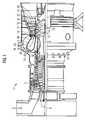
- einen Halbschnitt durch eine Gasturbine, und
- FIG 2
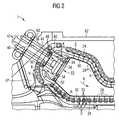
- im Schnitt einen Ausschnitt einer Gasturbine nach FIG 1.
- FIG. 1
- a half section through a gas turbine, and
- FIG 2
- in section a section of a gas turbine according to FIG. 1.
Gleiche Teile sind beiden Figuren mit den selben Bezugszeichen versehen.The same parts are provided with the same reference numerals in both figures.
Die Gasturbine 1 gemäß FIG 1 weist einen Verdichter 2 für Verbrennungsluft, eine Brennkammer 4 sowie eine Turbine 6 zum Antrieb des Verdichters 2 und eines nicht dargestellten Generators oder einer Arbeitsmaschine auf. Dazu sind die Turbine 6 und der Verdichter 2 auf einer gemeinsamen, auch als Turbinenläufer bezeichneten Turbinenwelle 8 angeordnet, mit der auch der Generator bzw. die Arbeitsmaschine verbunden ist, und die um ihre Mittelachse 9 drehbar gelagert ist. Die in der Art einer Ringbrennkammer ausgeführte Brennkammer 4 ist mit einer Anzahl von Brennern 10 zur Verbrennung eines flüssigen oder gasförmigen Brennstoffs B bestückt.The
Die Turbine 6 weist eine Anzahl von mit der Turbinenwelle 8 verbundenen, rotierbaren Laufschaufeln 12 auf. Die Laufschaufeln 12 sind kranzförmig an der Turbinenwelle 8 angeordnet und bilden somit eine Anzahl von Laufschaufelreihen. Weiterhin umfasst die Turbine 6 eine Anzahl von feststehenden Leitschaufeln 14, die ebenfalls kranzförmig unter der Bildung von Leitschaufelreihen an einem Innengehäuse 16 der Turbine 6 befestigt sind. Die Laufschaufeln 12 dienen dabei zum Antrieb der Turbinenwelle 8 durch Impulsübertrag vom die Turbine 6 durchströmenden Arbeitsmedium M. Die Leitschaufeln 14 dienen hingegen zur Strömungsführung des Arbeitsmediums M zwischen jeweils zwei in Strömungsrichtung des Arbeitsmediums M gesehen aufeinanderfolgenden Laufschaufelreihen oder Laufschaufelkränzen. Ein aufeinanderfolgendes Paar aus einem Kranz von Leitschaufeln 14 oder einer Leitschaufelreihe und aus einem Kranz von Laufschaufeln 12 oder einer Laufschaufelreihe wird dabei auch als Turbinenstufe bezeichnet.The turbine 6 has a number of
Jede Leitschaufel 14 weist eine auch als Schaufelfuß bezeichnete Plattform 18 auf, die zur Fixierung der jeweiligen Leitschaufel 14 am Innengehäuse 16 der Turbine 6 als Wandelement angeordnet ist. Die Plattform 18 ist dabei ein thermisch vergleichsweise stark belastetes Bauteil, das die äußere Begrenzung eines Heizgaskanals für das die Turbine 6 durchströmende Arbeitsmedium M bildet. Jede Laufschaufel 12 ist in analoger Weise über eine auch als Schaufelfuß bezeichnete Plattform 20 an der Turbinenwelle 8 befestigt.Each guide vane 14 has a
Zwischen den beabstandet voneinander angeordneten Plattformen 18 der Leitschaufeln 14 zweier benachbarter Leitschaufelreihen ist jeweils ein Führungsring 21 am Innengehäuse 16 der Turbine 6 angeordnet. Die äußere Oberfläche jedes Führungsrings 21 ist dabei ebenfalls dem heißen, die Turbine 6 durchströmenden Arbeitsmedium M ausgesetzt und in radialer Richtung vom äußeren Ende 22 der ihm gegenüber liegenden Laufschaufel 12 durch einen Spalt beabstandet. Die zwischen benachbarten Leitschaufelreihen angeordneten Führungsringe 21 dienen dabei insbesondere als Abdeckelemente, die die Innenwand 16 oder andere Gehäuse-Einbauteile vor einer thermischen Überbeanspruchung durch das die Turbine 6 durchströmende heiße Arbeitsmedium M schützt.Between the spaced-
Zur Erzielung eines vergleichsweise hohen Wirkungsgrades ist die Gasturbine 1 für eine vergleichsweise hohe Austrittstemperatur des aus der Brennkammer 4 austretenden Arbeitsmediums M von etwa 1200 °C bis 1500 °C ausgelegt. Sie ist weiterhin an ihrer Brennkammerwand 24 mit einer Innenauskleidung 26 mit nicht näher dargestellten Hitzeschildelementen versehen.In order to achieve a comparatively high efficiency, the
Um bei hoher betrieblicher Stabilität und Sicherheit eine hohe Leistungsdichte bei der Verbrennung zu gewährleisten, ist die Gasturbine 1 für eine zumindest teilweise Vorvermischung von Brennstoff B und Verbrennungsluft V vor dem eigentlichen Eintritt in die Brenner 10 ausgestaltet. Wie in FIG 2 im Schnitt dargestellt, ist dazu der Einströmbereich der Brenner 10 jeweils geeignet ausgestaltet.In order to ensure a high power density during combustion with high operational stability and safety, the
Wie in FIG 2 erkennbar, ist die als Ringbrennkammer ausgestaltete Brennkammer 4 der Gasturbine 1 für eine Luftkühlung ausgelegt. Dazu ist die Brennkammerwand 24 mit der aus Hitzeschildelementen 28 gebildeten Innenauskleidung 26 versehen, wobei die Hitzeschildelemente 28 unter Bildung eines Strömungsraums 30 für Kühlluft K beabstandet von der Brennkammerwand 24 angeordnet sind. Der Strömungsraum 30 ist dabei über eine Anzahl von Überströmöffnungen 32 mit zur Verwendung als Kühlluft K vorgesehener Verdichterluft V beaufschlagbar. Zur Erhöhung des Wirkungsgrads ist dabei vorgesehen, die bei der Kühlung der Brennkammer 4 aufgewärmte Kühlluft K als zusätzliche Verbrennungsluft dem Verbrennungsprozess zuzuführen. Dies erfolgt über geeignete Einströmöffnungen 34 im Gehäuse des Brenners 10.As can be seen in FIG. 2, the
Zur Abdichtung der Öffnungen 36 in der Brennkammerwand 24, durch die hindurch der Brenner 10 in das Innere der Brennkammer 4 hineingeführt ist, ist eine Abdichtplatte 38 vorgesehen. Die Abdichtplatte 38 stellt dabei sicher, dass ein Überströmen der rückzuführenden, bereits erwärmten Kühlluft K in den Strömungsraum der Verdichterluft V oder umgekehrt sicher vermieden ist. Für die gewünschte Vorvermischung von Brennstoff B und Verdichter- oder Verbrennungsluft V ist diese Abdichtplatte 38 mit einer Vormischkammer 40 versehen.A sealing
Der in der FIG 2 dargestellte Brenner 10 wird im Übrigen über eine Anzahl von Brennstoffzuführleitungen 42 mit Brennstoff B bespeist. Für die zumindest teilweise Vermischung von Brennstoff B und Verbrennungsluft V in Strömungsrichtung des Brennstoff-/Verbrennungsluft-Gemisches B, V vor dem Brenner 10 mündet eine der Brennstoffzuführleitungen 42 an einer Einspeisestelle 44 in der Vormischkammer 40, die zwischen der einströmenden Verbrennungsluft V aus dem Verdichter 2 und dem Strömungsraum 30 für die Kühlluft K der Brennkammerwand 4 angeordnet ist. Diese Brennstoffzuführleitung 42 dient somit als Brennstoff-Zweigleitung 46.The
Die Vormischkammer 40 weist im Ausführungsbeispiel eine ringförmige Struktur auf, die auf ihrem Querschnitt teilweise geöffnet ist, damit Verbrennungsluft V in die Vormischkammer 40 einströmen und diese wieder in Richtung Brenner 10 verlassen kann. Damit ist die Vormischkammer 40 gasseitig an den Verdichterluftkanal 47 angeschlossen. Um den Brennstoff B in diese Verbrennungsluft V einzumischen, weist die Brennstoff-Zweigleitung 46 im Bereich der Vormischkammer 40 eine Anzahl von Auslassbohrungen 48 auf. Die Dimensionierungen der Komponenten sind dabei derart gewählt, dass sich die Massenströme von Brennstoff B und Verbrennungsluft V derart einstellen, dass das in der Vormischkammer 40 entstehende Gemisch nicht zündfähig ist und beispielsweise einen Brennstoffanteil von 5 % bis 20 %, vorzugsweise von etwa 5 % bis 7 %, aufweist.In the exemplary embodiment, the premixing
Das in der Vormischkammer 40 vermischte Verbrennungsgemisch wird in den Brenner 10 geführt, wobei zuvor noch rückgeführte Kühlluft K der Brennkammerwand 4 dem Verbrennungsgemisch zugeführt wird. Im Brenner 10 und in der sich anschließenden Brennkammer 4 vermischt sich dann das Brennstoff-/Verbrennungsluft-Gemisch B, V mit dem Brennstoff B, der aus den direkt an den Brenner 10 angeschlossenen Brennstoffzuführleitungen 42 zuführbar ist.The combustion mixture mixed in the
Alternativ oder zusätzlich kann auch eine zumindest teilweise Vermischung von Brennstoff B und "verbrauchter" Kühlluft K als Verbrennungsluft in der Vormischkammer 40 vorgesehen sein. Dazu kann die Vormischkammer 40 über Überströmöffnungen 50 mit dem Sammelraum 52 für die aus dem Strömungsraum 30 abströmende Kühlluft K verbunden sein.Alternatively or additionally, an at least partial mixing of fuel B and “used” cooling air K as combustion air can also be provided in the
Im Ausführungsbeispiel ist die Vormischkammer 40 in die Abdichtplatte 38 integriert, was eine besonders platzsparende Bauweise ermöglicht. Alternativ oder zusätzlich könnte die Vormischkammer 40 aber auch als separates Bauteil, insbesondere als an der Abdichtplatte 38 angeordnete Ringleitung, ausgeführt sein.In the exemplary embodiment, the premixing
Um den Brenner 10 bzw. die Brennstoffzuführleitungen 42 des Brenners 10 nicht im Bereich der Mischkammer 40 an der Brennkammer 4 zu befestigen, ist der Brenner 10 über die Brennstoffzuführleitungen 42 bzw. über die sie haltende Tragstruktur über eine Befestigungsvorrichtung 60 am Gasturbinengehäuse 62 befestigt.In order not to fasten the
Claims (10)
Translated fromGermanPriority Applications (2)
| Application Number | Priority Date | Filing Date | Title |
|---|---|---|---|
| EP03006466AEP1460339A1 (en) | 2003-03-21 | 2003-03-21 | Gas turbine |
| PCT/EP2004/002292WO2004083731A1 (en) | 2003-03-21 | 2004-03-05 | Gas turbine |
Applications Claiming Priority (1)
| Application Number | Priority Date | Filing Date | Title |
|---|---|---|---|
| EP03006466AEP1460339A1 (en) | 2003-03-21 | 2003-03-21 | Gas turbine |
Publications (1)
| Publication Number | Publication Date |
|---|---|
| EP1460339A1true EP1460339A1 (en) | 2004-09-22 |
Family
ID=32798861
Family Applications (1)
| Application Number | Title | Priority Date | Filing Date |
|---|---|---|---|
| EP03006466AWithdrawnEP1460339A1 (en) | 2003-03-21 | 2003-03-21 | Gas turbine |
Country Status (2)
| Country | Link |
|---|---|
| EP (1) | EP1460339A1 (en) |
| WO (1) | WO2004083731A1 (en) |
Families Citing this family (2)
| Publication number | Priority date | Publication date | Assignee | Title |
|---|---|---|---|---|
| EP3015772B1 (en)* | 2014-10-31 | 2020-01-08 | Ansaldo Energia Switzerland AG | Combustor arrangement for a gas turbine |
| DE102015215207A1 (en)* | 2015-08-10 | 2017-02-16 | Siemens Aktiengesellschaft | Combustion chamber for a gas turbine and heat shield element for lining such a combustion chamber |
Citations (4)
| Publication number | Priority date | Publication date | Assignee | Title |
|---|---|---|---|---|
| US4236378A (en)* | 1978-03-01 | 1980-12-02 | General Electric Company | Sectoral combustor for burning low-BTU fuel gas |
| WO1999046540A1 (en)* | 1998-03-10 | 1999-09-16 | Siemens Aktiengesellschaft | Combustion chamber and method for operating a combustion chamber |
| WO2001059369A1 (en)* | 2000-02-14 | 2001-08-16 | Ulstein Turbine As | Device in a burner for gas turbines |
| WO2002088601A1 (en)* | 2001-04-27 | 2002-11-07 | Siemens Aktiengesellschaft | Combustion chamber, in particular of a gas turbine |
Family Cites Families (2)
| Publication number | Priority date | Publication date | Assignee | Title |
|---|---|---|---|---|
| JP2001510885A (en)* | 1997-07-17 | 2001-08-07 | シーメンス アクチエンゲゼルシヤフト | Burner device for combustion equipment, especially for gas turbine combustors |
| GB0111788D0 (en)* | 2001-05-15 | 2001-07-04 | Rolls Royce Plc | A combustion chamber |
- 2003
- 2003-03-21EPEP03006466Apatent/EP1460339A1/ennot_activeWithdrawn
- 2004
- 2004-03-05WOPCT/EP2004/002292patent/WO2004083731A1/enactiveApplication Filing
Patent Citations (4)
| Publication number | Priority date | Publication date | Assignee | Title |
|---|---|---|---|---|
| US4236378A (en)* | 1978-03-01 | 1980-12-02 | General Electric Company | Sectoral combustor for burning low-BTU fuel gas |
| WO1999046540A1 (en)* | 1998-03-10 | 1999-09-16 | Siemens Aktiengesellschaft | Combustion chamber and method for operating a combustion chamber |
| WO2001059369A1 (en)* | 2000-02-14 | 2001-08-16 | Ulstein Turbine As | Device in a burner for gas turbines |
| WO2002088601A1 (en)* | 2001-04-27 | 2002-11-07 | Siemens Aktiengesellschaft | Combustion chamber, in particular of a gas turbine |
Also Published As
| Publication number | Publication date |
|---|---|
| WO2004083731A1 (en) | 2004-09-30 |
Similar Documents
| Publication | Publication Date | Title |
|---|---|---|
| EP1947293B1 (en) | Guide vane for a gas turbine | |
| DE102009043883A1 (en) | Multiple tube thermal fuse to protect a nozzle from a flame holding or flashback event | |
| WO2005019730A1 (en) | Heat shield arrangement for a hot gas-guiding component, particularly for a combustion chamber of a gas turbine | |
| EP2808611B1 (en) | Injector for introducing a fuel-air mixture into a combustion chamber | |
| WO2014191495A1 (en) | Annular combustion chamber for a gas turbine, with tangential injection for late lean injection | |
| CH701961A2 (en) | Turbomachine. | |
| EP1245806B1 (en) | Cooled gas turbine balde | |
| DE10035676A1 (en) | Gas turbine and method for operating a gas turbine | |
| EP1880140A1 (en) | Combustion chamber wall, gas turbine installation and process for starting or shutting down a gas turbine installation | |
| WO2008052846A1 (en) | Turbine blade | |
| EP1249578A1 (en) | Cooling of a gas turbine | |
| DE60122619T2 (en) | Gas turbine combustion chamber wall | |
| EP1467151A1 (en) | Heat shield element | |
| EP1662202B1 (en) | Burner for a gas turbine | |
| EP1460339A1 (en) | Gas turbine | |
| EP2808610A1 (en) | Gas turbine combustion chamber with tangential late lean injection | |
| EP1537363A1 (en) | Gas turbine | |
| EP1588102B1 (en) | Heat shield element, combustion chamber and gas turbine | |
| EP0597137B1 (en) | Combustion chamber for gas turbine | |
| DE4415916A1 (en) | Method of combusting fluidic fuel in air stream | |
| EP2846096A1 (en) | Tubular combustion chamber with a flame tube and area and gas turbine | |
| WO2004109187A1 (en) | Heat shield element | |
| EP1529181B1 (en) | Gas turbine combustion chamber | |
| EP1731715A1 (en) | Transition between a combustion chamber and a turbine | |
| EP2808612A1 (en) | Gas turbine combustion chamber with tangential late lean injection |
Legal Events
| Date | Code | Title | Description |
|---|---|---|---|
| PUAI | Public reference made under article 153(3) epc to a published international application that has entered the european phase | Free format text:ORIGINAL CODE: 0009012 | |
| AK | Designated contracting states | Kind code of ref document:A1 Designated state(s):AT BE BG CH CY CZ DE DK EE ES FI FR GB GR HU IE IT LI LU MC NL PT RO SE SI SK TR | |
| AX | Request for extension of the european patent | Extension state:AL LT LV MK | |
| AKX | Designation fees paid | ||
| REG | Reference to a national code | Ref country code:DE Ref legal event code:8566 | |
| STAA | Information on the status of an ep patent application or granted ep patent | Free format text:STATUS: THE APPLICATION IS DEEMED TO BE WITHDRAWN | |
| 18D | Application deemed to be withdrawn | Effective date:20050323 |