EP1458299B1 - Device for performing osteosynthesis - Google Patents
Device for performing osteosynthesisDownload PDFInfo
- Publication number
- EP1458299B1 EP1458299B1EP01275091AEP01275091AEP1458299B1EP 1458299 B1EP1458299 B1EP 1458299B1EP 01275091 AEP01275091 AEP 01275091AEP 01275091 AEP01275091 AEP 01275091AEP 1458299 B1EP1458299 B1EP 1458299B1
- Authority
- EP
- European Patent Office
- Prior art keywords
- bushing
- hole
- section
- cross
- bore
- Prior art date
- Legal status (The legal status is an assumption and is not a legal conclusion. Google has not performed a legal analysis and makes no representation as to the accuracy of the status listed.)
- Expired - Lifetime
Links
Images


Classifications
- A—HUMAN NECESSITIES
- A61—MEDICAL OR VETERINARY SCIENCE; HYGIENE
- A61B—DIAGNOSIS; SURGERY; IDENTIFICATION
- A61B17/00—Surgical instruments, devices or methods
- A61B17/56—Surgical instruments or methods for treatment of bones or joints; Devices specially adapted therefor
- A61B17/58—Surgical instruments or methods for treatment of bones or joints; Devices specially adapted therefor for osteosynthesis, e.g. bone plates, screws or setting implements
- A61B17/68—Internal fixation devices, including fasteners and spinal fixators, even if a part thereof projects from the skin
- A61B17/80—Cortical plates, i.e. bone plates; Instruments for holding or positioning cortical plates, or for compressing bones attached to cortical plates
- A61B17/8033—Cortical plates, i.e. bone plates; Instruments for holding or positioning cortical plates, or for compressing bones attached to cortical plates having indirect contact with screw heads, or having contact with screw heads maintained with the aid of additional components, e.g. nuts, wedges or head covers
- A61B17/8047—Cortical plates, i.e. bone plates; Instruments for holding or positioning cortical plates, or for compressing bones attached to cortical plates having indirect contact with screw heads, or having contact with screw heads maintained with the aid of additional components, e.g. nuts, wedges or head covers wherein the additional element surrounds the screw head in the plate hole
- A—HUMAN NECESSITIES
- A61—MEDICAL OR VETERINARY SCIENCE; HYGIENE
- A61B—DIAGNOSIS; SURGERY; IDENTIFICATION
- A61B17/00—Surgical instruments, devices or methods
- A61B17/56—Surgical instruments or methods for treatment of bones or joints; Devices specially adapted therefor
- A61B17/58—Surgical instruments or methods for treatment of bones or joints; Devices specially adapted therefor for osteosynthesis, e.g. bone plates, screws or setting implements
- A61B17/68—Internal fixation devices, including fasteners and spinal fixators, even if a part thereof projects from the skin
- A61B17/84—Fasteners therefor or fasteners being internal fixation devices
- A61B17/86—Pins or screws or threaded wires; nuts therefor
- A61B17/8695—Washers
Definitions
- the inventionrelates to a device for osteosynthesis according to the preamble of claim 1.
- Such devicesbecome polyaxial, rigid Gland used, especially in the field of Spine, for example for pedicle screws or Pedikelhaken. But you can also generally for plate osteosynthesis be used. There are also fixator applications external as well as for intervertebral implants possible.
- the inventionaims to remedy this situation.
- the inventionis the problem underlying a device for osteosynthesis too create, in which the bone screws relative to Bone plate can be moved in a polyaxial way and locked in position are without the need for additional mechanical components are.
- the inventionachieves the stated object with a device which has the features of claim 1.
- each of the exactly circular oneswill be called “non-circular" Area deviating cross section called, in particular prismatic and elliptical cross sections.
- the Hexagonal designallows the bone screw in pivot hexagonal passage simultaneously in three planes, so that any pivot angle is adjustable. This is only by the plate thickness and by the abutment of the Insert limited to the cross-sectional constriction. It can Of course, also used bone plates with multiple passes become.
- the diameter of the central bore of the inserttapers in one direction and the bore preferably formed as a cone.
- This embodimentallows a spreading of the insert by means of a Counter-cone.
- the hole of the insertcan also be formed circular cylindrical.
- the bore of the insertwith a Provided internal thread. This allows a locking of the Insert.
- the orthogonal to the central axis cross section of the Passage in the preferably designed as a bone plate Osteosynthetic devicemay also be elliptical be educated.
- the cross sectionexists the passage of two incomplete semicircles, which with non-circular lines are connected.
- the insert pointsthen on its outer surface corresponding to two pins on which in through the non-circular lines in the passage formed grooves are used.
- the insertradially compressible and radially expandable too
- Thiscan be a continuous, preferably parallel to the longitudinal axis of the insert extending slot exhibit.
- the missionmay include several, Preferably, parallel to the longitudinal axis extending, non-continuous Have slots.
- the surface of the insertpreferably in the area of his peripheral outer surface is conveniently roughened, e.g. rough blasted. Accordingly, the passage in the Bone plate roughened, e.g. be rough blasted.
- the surface of the insertcan also, preferably in Area of its peripheral outer surface, with a macrostructure be provided, e.g. in the form of peripheral peripheral Grooves.
- the passagecan then in a similar way with macrostructuring, e.g. in the form of peripheral circumferential grooves.
- the tapered Passage in thepreferably designed as a bone plate osteosynthetic device against the underside and preferably also towards the top, so that a Narrowing results in the falling out or Pressing out of the insert prevented.
- a Narrowingresults in the falling out or Pressing out of the insert prevented.
- peripheral outer surface of the insertis expediently convex, preferably cylindrical.
- the osteosynthetic deviceis - at least in the area of their passage - and the use - also at least in the area of its peripheral outer surface - made of different materials, preferably those with different hardness.
- the usecan for example a biocompatible plastic and the osteosynthetic device (e.g., a bone plate) a body-friendly metal.
- the usecan also be metallic and the device made of a plastic, preferably a reinforced plastic. The different ones Materials cause a plastic deformation of the surfaces and thereby a positive connection.
- the height of the insertshould be in the direction of its longitudinal axis measured to be less than the height of the passage in the Bone plate measured in the direction of its central axis.
- the amount of the missionis conveniently in the range of 40% - 85%, preferably from 45% to 65% of the height of the passage.
- the bone screws used for insertion into the insertpreferably have a conical screw head, which with an external thread is provided.
- the advantage of this Embodimentis that the spreading and locking of the Use in a single step is possible.
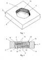
- the device shown in FIGS. 1 to 4 for the Osteosynthesisconsists of a bone plate 1 with a for the plant to the bone certain base 2, a top 3, and a the bottom 2 with the top 3 connecting Passage 4 for receiving a multiaxial pivoting Insert 10 for a bone screw 20 (FIG. 8), wherein the Passage 4 has a central axis 5.
- the one in the passage 4 usable insert 10(Fig. 3) has a central Bore 11 for receiving the bone screw 20 (Fig. 8), wherein the bore 11 has a longitudinal axis 12, and a peripheral Outer surface 17, which for contact with the passage 4th is determined.
- the insert 10has a continuous slot 13, so that it is radially compressible and radially expandable.
- a cross-sectional constriction 9on to the falling out or pushing out of the insert 10 to prevent.
- the cross-sectional constriction 9 of the passage 4 and the Compressibility of the insert 10are one upon another that matched the insert 10 in the compressed state in the Passage 4 can be introduced.
- the surface of the insert 10is in Area of its peripheral outer surface 17 with a macrostructure in the form of peripheral circumferential grooves 18 Mistake. Accordingly, the passage 4 of the bone plate 1 with a macrostructuring in the form of peripherally circulating Grooves 19 (Fig. 2) provided.
- the orthogonal to the central axis 5 standing cross section 6 of the passage 4is approximately hexagonal, that is formed out of round.
- the orthogonal to the longitudinal axis 12 standing cross-section 16 of the insert 10has a cross-section 6 of the passage 4 of the bone plate 1 substantially corresponding shape, so that the inserted in the passage 4 insert 10 is rotationally fixed relative to its longitudinal axis 12, but within the passage 4th remains pivotable relative to the bone plate 1.
- the diameter of the bore 11tapers in the direction of the bottom 2 of the bone plate 1, so that the bore 11 is tapered.
- the bore 11also has an internal thread 15.
- FIG. 5shows another embodiment of the insert 10 shown, the more, parallel to the longitudinal axis 12th extending, non-continuous slots 14 has. Thereby the insert 10 is radial even without a continuous slot compressible and radially expandable.
- Figs. 6 and 7is another embodiment of the Insert 10 and the corresponding bone plate 1 represented, in which the cross section 6 of the passage 4th is defined by two incomplete semicircles 7, which are connected by two non-circular lines 8.
- the in Fig. 7 illustrated inserthas accordingly a ring on, whose peripheral outer surface 17 is spherical and the has two diametrically arranged, hemispherical pin 26.
- the two pins 26are accommodated in the non-circular Lines 8 grooves formed in also spherical Passage 4 of the bone plate 1.
- the insert 10is in inserted state both around its two pins 26 as well rotatable orthogonal to this axis of rotation, so that all Pivoting movements are possible, except for a rotation in the Plate plane (universal joint).
- the bone screw shown in Fig. 8 20are used.
- the bone screw 20has a threaded shaft 21 intended to be anchored in the bone, a screw axis 23, and one for insertion into the central bore 11 of the insert 10 certain screw head 22, which corresponds substantially to the shape of the bore 11.
- the orthogonal to the screw axis 23 standing Cross section through the screw head 22is against the threaded shaft 21 tapers so that a cone results.
- the screw head 22is provided with an external thread 24, which corresponds to the internal thread 15 of the insert 10.
- the screw head 22has a hexagon socket 15 for receiving a (not shown in the drawing) Hex screwdriver.
Landscapes
- Health & Medical Sciences (AREA)
- Orthopedic Medicine & Surgery (AREA)
- Surgery (AREA)
- Life Sciences & Earth Sciences (AREA)
- Heart & Thoracic Surgery (AREA)
- Nuclear Medicine, Radiotherapy & Molecular Imaging (AREA)
- Engineering & Computer Science (AREA)
- Biomedical Technology (AREA)
- Neurology (AREA)
- Medical Informatics (AREA)
- Molecular Biology (AREA)
- Animal Behavior & Ethology (AREA)
- General Health & Medical Sciences (AREA)
- Public Health (AREA)
- Veterinary Medicine (AREA)
- Surgical Instruments (AREA)
- Prostheses (AREA)
Description
Translated fromGermanDie Erfindung betrifft eine Vorrichtung für die Osteosynthesegemäss dem Oberbegriff des Patentanspruchs 1.The invention relates to a device for osteosynthesisaccording to the preamble of
Solche Vorrichtungen werden zur polyaxialen, rigidenVerschraubung verwendet, insbesondere im Bereich derWirbelsäule, beispielsweise für Pedikelschrauben oder Pedikelhaken.Sie können aber auch generell zur Plattenosteosyntheseverwendet werden. Zudem sind auch Anwendungen für Fixateurexternes sowie für Zwischenwirbleimplantate möglich.Such devices become polyaxial, rigidGland used, especially in the field ofSpine, for example for pedicle screws or Pedikelhaken.But you can also generally for plate osteosynthesisbe used. There are also fixator applicationsexternal as well as for intervertebral implants possible.
Aus der US 6,235,033(Basis für den Oberbegriff des Anspruch 1)ist bereits eine derartige Vorrichtungbekannt, bei der zwischen dem Schraubenkopf und der Bohrungder Knochenplatte ein schwenkbarer, ringförmiger Einsatzvorhanden ist, welcher mittels eines Schlitzes komprimierbarund expandierbar ist, um damit eine verbesserte Fixationzwischen Schraube und Platte zu erreichen. Der Nachteil dieserbekannten Vorrichtung besteht darin, dass der verwendete Einsatzkreisrund ausgebildet ist, so dass er beim Schraubeneindrehenmitdrehen kann und dadurch das Verriegeln verhindert. DerEinsatz kann sich aber auch ganz innerhalb der Plattenbohrung verdrehen, so dass er dann mit der falschen Seite (Innenkonusverjüngt sich in die falsche Richtung) nach oben zu liegenkommt.From US 6,235,033(Basis for the preamble of claim 1)is already such a deviceknown at the between the screw head and the borethe bone plate is a swiveling, annular insertis present, which is compressible by means of a slotand expandable to provide improved fixationbetween the screw and the plate. The disadvantage of thisknown device is that the use usedis circular, so that he screwing in the screwcan rotate with it, thereby preventing the locking. Of theUse can also be quite within the plate boretwist it, so that it then with the wrong side (inner conetapers in the wrong direction)comes.
Die obenstehende Diskussion des Standes der Technik erfolgtlediglich zur Erläuterung des Umfeldes der Erfindung undbedeutet nicht, dass der zitierte Stand der Technik zumZeitpunkt dieser Anmeldung auch tatsächlichpubliziert oder öffentlich bekannt war.The above discussion of the prior art is mademerely to explain the environment of the invention anddoes not mean that the cited prior art forDate of this application actuallypublished or publicly known.
Hier will die Erfindung Abhilfe schaffen. Der Erfindung liegtdas Problem zugrunde, eine Vorrichtung für die Osteosynthese zuschaffen, bei welcher die Knochenschrauben relativ zurKnochenplatte polyaxial beweglich und winkelstabil verriegelbarsind, ohne dass dazu zusätzliche mechanische Bauteile notwendigsind.The invention aims to remedy this situation. The invention isthe problem underlying a device for osteosynthesis toocreate, in which the bone screws relative toBone plate can be moved in a polyaxial way and locked in positionare without the need for additional mechanical componentsare.
Die Erfindung löst die gestellte Aufgabe mit einer Vorrichtung,welche die Merkmale des Anspruchs 1 aufweist.The invention achieves the stated object with a devicewhich has the features of
Als "unrund" wird im folgenden jeder von der exakt kreisförmigenFläche abweichende Querschnitt bezeichnet, insbesondereprismatische und elliptische Querschnitte.In the following, each of the exactly circular ones will be called "non-circular"Area deviating cross section called, in particularprismatic and elliptical cross sections.
Damit ist der Vorteil erzielbar, dass sich der Einsatz beimEinschrauben der Knochenschraube nicht mehr um seine eigeneAchse drehen kann. Letzteres würde nämlich dazu führen, dasskeine Relativbewegung mehr zwischen Einsatz und Schraube stattfände, so dass auch kein Aufspreizen des Einsatzes mehrmöglich wäre und damit auch keine Verriegelung der Schraube. Einweiterer Vorteil besteht darin, dass keine zusätzlicheSpreizschraube notwendig ist, wie dies bei der US 6,235,033nötig ist.Thus, the advantage is achieved that the use in theScrewing the bone screw no longer around his ownAxis can rotate. The latter would lead to the fact thatno relative movement between insert and screwtake place, so that no spreading of the use morewould be possible and thus no locking of the screw. OneAnother advantage is that no additionalSpreizschraube is necessary, as in the US 6,235,033is necessary.
Bei einer besonderen Ausführungsform ist der Querschnitt desDurchgangs in der vorzugsweise als Knochenplatte ausgebildetenosteosynthetischen Vorrichtung polygonal, vorzugsweisehexagonal, ausgebildet, so dass der Durchgang ein Prisma,vorzugsweise ein sechsseitiges Prisma darstellt. Bei derhexagonalen Ausführung lässt sich die Knochenschraube imsechskantigen Durchgang gleichzeitig in drei Ebenen schwenken,so dass jeder beliebige Schwenkwinkel einstellbar ist. Dieserist nur durch die Plattendicke und durch das Anstossen desEinsatzes an der Querschnittsverengung begrenzt. Es könnennatürlich auch Knochenplatten mit mehreren Durchgängen verwendetwerden.In a particular embodiment, the cross section of thePassage in the preferably designed as a bone plateosteosynthetic device polygonal, preferablyhexagonal, formed so that the passage is a prism,preferably represents a six-sided prism. In theHexagonal design allows the bone screw inpivot hexagonal passage simultaneously in three planes,so that any pivot angle is adjustable. Thisis only by the plate thickness and by the abutment of theInsert limited to the cross-sectional constriction. It canOf course, also used bone plates with multiple passesbecome.
Bei einer weiteren Ausführungsform ist der Durchmesser derzentralen Bohrung des Einsatzes in einer Richtung verjüngt unddie Bohrung vorzugsweise als Konus augebildet. Diese Ausgestaltungerlaubt eine Aufspreizung des Einsatzes mittels einesGegenkonus. Die Bohrung des Einsatzes kann aber auchkreiszylindrisch ausgebildet sein.In a further embodiment, the diameter of thecentral bore of the insert tapers in one direction andthe bore preferably formed as a cone. This embodimentallows a spreading of the insert by means of aCounter-cone. But the hole of the insert can alsobe formed circular cylindrical.
Vorzugsweise ist die Bohrung des Einsatzes mit einemInnengewinde versehen. Dies gestattet eine Verriegelung desEinsatzes.Preferably, the bore of the insert with aProvided internal thread. This allows a locking of theInsert.
Der orthogonal zur Zentralachse stehende Querschnitt desDurchgangs in der vorzugsweise als Knochenplatte ausgebildetenosteosynthetischen Vorrichtung kann auch ellipsenförmigausgebildet sein.The orthogonal to the central axis cross section of thePassage in the preferably designed as a bone plateOsteosynthetic device may also be ellipticalbe educated.
Bei einer speziellen Ausführungsform besteht der Querschnittdes Durchgangs aus zwei unvollständigen Halbkreisen, welche mitnicht-kreisförmigen Linien verbunden sind. Der Einsatz weistdann auf seiner Aussenfläche entsprechend zwei Zapfen auf,welche in die durch die nicht-kreisförmigen Linien im Durchganggebildeten Nuten einsetzbar sind.In a specific embodiment, the cross section existsthe passage of two incomplete semicircles, which withnon-circular lines are connected. The insert pointsthen on its outer surface corresponding to two pins onwhich in through the non-circular lines in the passageformed grooves are used.
Um den Einsatz radial komprimierbar und radial expandierbar zugestalten, kann dieser einen durchgehenden, vorzugsweiseparallel zur Längsachse des Einsatzes verlaufenden Schlitzaufweisen. Alternativ dazu kann der Einsatz auch mehrere,vorzugsweise parallel zur Längsachse verlaufende, nicht-durchgehendeSchlitze aufweisen.To make the insert radially compressible and radially expandable tooThis can be a continuous, preferablyparallel to the longitudinal axis of the insert extending slotexhibit. Alternatively, the mission may include several,Preferably, parallel to the longitudinal axis extending, non-continuousHave slots.
Die Oberfläche des Einsatzes, vorzugsweise im Bereich seinerperipheren Aussenfläche, ist zweckmässigerweise aufgerauht,z.B. rauh gestrahlt. Entsprechend kann der Durchgang in derKnochenplatte aufgerauht, z.B. rauh gestrahlt sein.The surface of the insert, preferably in the area of hisperipheral outer surface is conveniently roughened,e.g. rough blasted. Accordingly, the passage in theBone plate roughened, e.g. be rough blasted.
Die Oberfläche des Einsatzes kann aber auch, vorzugsweise imBereich seiner peripheren Aussenfläche, mit einer Makrostrukturierungversehen sein, z.B. in Form peripher umlaufenderRillen. Der Durchgang kann dann in entsprechender Weise miteiner Makrostrukturierung versehen sein, z.B. in Form peripherumlaufender Rillen. Der Vorteil dieser Ausgestaltung liegt inder damit erzielten formschlüssigen Verbindung zwischen Einsatzund Knochenplatte.But the surface of the insert can also, preferably inArea of its peripheral outer surface, with a macrostructurebe provided, e.g. in the form of peripheral peripheralGrooves. The passage can then in a similar way withmacrostructuring, e.g. in the form of peripheralcircumferential grooves. The advantage of this embodiment is inthe thus achieved positive connection between useand bone plate.
Bei einer weiteren speziellen Ausführungsform verjüngt sich derDurchgang in der vorzugsweise als Knochenplatte ausgebildetenosteosynthetischen Vorrichtung gegen die Unterseite hin undvorzugsweise auch gegen die Oberseite hin, so dass eineQuerschnittsverengung resultiert, welche das Herausfallen oderHerausdrücken des Einsatzes verhindert. Zweckmässigerweisewerden dabei die Querschnittsverengung des Durchgangs und dieKomprimierbarkeit des Einsatzes derart aufeinander abgestimmt,dass der Einsatz im komprimierten Zustand in den Durchgangeinbringbar ist.In another specific embodiment, the taperedPassage in the preferably designed as a bone plateosteosynthetic device against the underside andpreferably also towards the top, so that aNarrowing results in the falling out orPressing out of the insert prevented. Conveniently,are doing the cross-sectional constriction of the passage and theCompressibility of the insert so matched,that the insert in the compressed state in the passagecan be introduced.
Die periphere Aussenfläche des Einsatzes ist zweckmässigerweisekonvex, vorzugsweise zylinderförmig ausgebildet.The peripheral outer surface of the insert is expedientlyconvex, preferably cylindrical.
Vorteilhafterweise besteht die osteosynthetische Vorrichtung -mindestens im Bereich ihres Durchganges - und der Einsatz -ebenfalls mindestens im Bereich seiner peripheren Aussenfläche -aus verschiedenen Materialien, vorzugsweise solchen mitunterschiedlicher Härte. Der Einsatz kann beispielsweise aus einem biokompatiblen Kunststoff bestehen und dieosteosynthetische Vorrichtung (z.B. eine Knochenplatte) auseinem körperverträglichen Metall. Der Einsatz kann auch abermetallisch sein und die Vorrichtung aus einem Kunststoff,vorzugsweise einem verstärkten Kunststoff. Die unterschiedlichenMaterialien bewirken eine plastische Verformung der Oberflächenund dadurch einen Formschluss.Advantageously, the osteosynthetic device is -at least in the area of their passage - and the use -also at least in the area of its peripheral outer surface -made of different materials, preferably those withdifferent hardness. The use can for examplea biocompatible plastic and theosteosynthetic device (e.g., a bone plate)a body-friendly metal. The use can alsobe metallic and the device made of a plastic,preferably a reinforced plastic. The different onesMaterials cause a plastic deformation of the surfacesand thereby a positive connection.
Die Höhe des Einsatzes sollte in Richtung seiner Längsachsegemessen, kleiner sein als die Höhe des Durchgangs in derKnochenplatte in Richtung seiner Zentralachse gemessen. DieHöhe des Einsatzes liegt zweckmässigerweise im Bereich von 40 %- 85 %, vorzugsweise von 45 % bis 65 % der Höhe des Durchgangs.The height of the insert should be in the direction of its longitudinal axismeasured to be less than the height of the passage in theBone plate measured in the direction of its central axis. TheThe amount of the mission is conveniently in the range of 40%- 85%, preferably from 45% to 65% of the height of the passage.
Die zur Einführung in den Einsatz dienenden Knochenschraubenweisen vorzugsweise einen konischen Schraubenkopf auf, der miteinem Aussengewinde versehen ist. Der Vorteil dieserAusgestaltung liegt darin, dass das Spreizen und Verriegeln desEinsatzes in einem einzigen Schritt ermöglicht wird.The bone screws used for insertion into the insertpreferably have a conical screw head, which withan external thread is provided. The advantage of thisEmbodiment is that the spreading and locking of theUse in a single step is possible.
Die Erfindung und Weiterbildungen der Erfindung werden imfolgenden anhand der teilweise schematischen Darstellungenmehrerer Ausführungsbeispiele noch näher erläutert. AlleAusführungsbeispiele beziehen sich auf eine Knochenplatte alsosteosynthetische Vorrichtung. Analoge Anwendungen fürPedikelschrauben, Pedikelhaken, Fixateur externes oderZwischenwirbelimplantate sind möglich.The invention and developments of the invention are infollowing with the partial schematic representationsseveral embodiments explained in more detail. AllEmbodiments relate to a bone plate asosteosynthetic device. Analog applications forPedicle screws, pedicle hook, external fixator orIntervertebral implants are possible.
Es zeigen:
- Fig. 1
- eine perspektivische Darstellung einer in Formeiner Knochenplatte realisierten Vorrichtung für dieOsteosynthese;
- Fig. 2
- einen Querschnitt durch die Knochenplatte nach Fig.1 mit einem eingesetzten Einsatz;
- Fig. 3
- eine perspektivische Darstellung eines Einsatzes fürdie Vorrichtung für die Osteosynthese;
- Fig. 4
- einen horizontalen Querschnitt durch den Einsatznach Fig. 3;
- Fig. 5
- eine perspektivische Darstellung eines Einsatzes fürdie Vorrichtung für die Osteosynthese;
- Fig. 6
- einen horizontalen Querschnitt durch eine Varianteder Knochenplatte;
- Fig. 7
- eine perspektivische Darstellung eines Einsatzes fürdie Vorrichtung für die Osteosynthese passend zurKnochenplatte nach Fig. 6; und
- Fig. 8
- einen Längsschnitt durch eine Knochenschraube fürdie Vorrichtung für die Osteosynthese.
- Fig. 1
- a perspective view of a realized in the form of a bone plate device for osteosynthesis;
- Fig. 2
- a cross-section through the bone plate of Figure 1 with an inserted insert.
- Fig. 3
- a perspective view of an insert for the device for osteosynthesis;
- Fig. 4
- a horizontal cross section through the insert of Fig. 3;
- Fig. 5
- a perspective view of an insert for the device for osteosynthesis;
- Fig. 6
- a horizontal cross section through a variant of the bone plate;
- Fig. 7
- a perspective view of an insert for the device for osteosynthesis fitting to the bone plate of Fig. 6; and
- Fig. 8
- a longitudinal section through a bone screw for the device for osteosynthesis.
Die in den Fig. 1 bis 4 dargestellte Vorrichtung für dieOsteosynthese besteht aus einer Knochenplatte 1 mit einer fürdie Anlage zum Knochen bestimmten Unterseite 2, einer Oberseite3, sowie einem die Unterseite 2 mit der Oberseite 3 verbindendenDurchgang 4 zur Aufnahme eines multiaxial schwenkbarenEinsatzes 10 für eine Knochenschraube 20 (Fig. 8), wobei derDurchgang 4 eine Zentralachse 5 aufweist. Der in den Durchgang4 einsetzbare Einsatz 10 (Fig. 3) besitzt eine zentraleBohrung 11 zur Aufnahme der Knochenschraube 20 (Fig. 8), wobeidie Bohrung 11 eine Längsachse 12 aufweist, sowie eine periphereAussenfläche 17, welche für den Kontakt mit dem Durchgang 4bestimmt ist.The device shown in FIGS. 1 to 4 for theOsteosynthesis consists of a
Der Einsatz 10 weist einen durchgehenden Schlitz 13 auf, so dasser radial komprimierbar und radial expandierbar ist. DerDurchgang 4 der Knochenplatte 1 weist gegen die Unterseite 2und auch gegen die Oberseite 3 hin, eine Querschnittsverengung 9auf, um das Herausfallen oder Herausdrücken des Einsatzes 10 zuverhindern. Die Querschnittsverengung 9 des Durchgangs 4 und dieKomprimierbarkeit des Einsatzes 10 sind derart aufeinanderabgestimmt, dass der Einsatz 10 im komprimierten Zustand in denDurchgang 4 einbringbar ist.The
Wie in Fig. 3 gezeigt, ist die Oberfläche des Einsatzes 10 imBereich seiner peripheren Aussenfläche 17 mit einer Makrostrukturierungin Form von peripher umlaufenden Rillen 18 versehen. Entsprechend ist der Durchgang 4 der Knochenplatte 1mit einer Makrostrukturierung in Form peripher umlaufenderRillen 19 (Fig. 2) versehen.As shown in Fig. 3, the surface of the
Wie in Fig. 4 gezeigt, ist der orthogonal zur Zentralachse 5stehende Querschnitt 6 des Durchgangs 4 annähernd hexagonal,d.h. unrund ausgebildet ist. Der orthogonal zur Längsachse 12stehende Querschnitt 16 des Einsatzes 10 weist eine zumQuerschnitt 6 des Durchganges 4 der Knochenplatte 1 im wesentlichenkorrespondierende Form auf, so dass der im Durchgang 4eingesetzte Einsatz 10 relativ zu seiner Längsachse 12rotationsfest ist, aber innerhalb des Durchgangs 4 relativ zurKnochenplatte 1 schwenkbar bleibt.
Wie in Fig. 2 dargestellt, verjüngt sich der Durchmesser derBohrung 11 in Richtung der Unterseite 2 der Knochenplatte 1hin, so dass die Bohrung 11 konisch augebildet ist. Die Bohrung11 weist zudem ein Innengewinde 15 auf.As shown in Fig. 4, the orthogonal to the
As shown in Fig. 2, the diameter of the
In Fig. 5 ist eine andere Ausführungsform des Einsatzes 10dargestellt, der mehrere, parallel zur Längsachse 12verlaufende, nicht-durchgehende Schlitze 14 aufweist. Dadurchwird der Einsatz 10 auch ohne durchgehenden Schlitz radialkomprimierbar und radial expandierbar.FIG. 5 shows another embodiment of the
In den Fig. 6 und 7 ist eine andere Ausführungsform desEinsatzes 10 und der dazu korrespondierenden Knochenplatte 1dargestellt, bei welcher der Querschnitt 6 des Durchganges 4durch zwei unvollständige Halbkreise 7 definiert wird, welche durch zwei nicht-kreisförmige Linien 8 verbunden sind. Der inFig. 7 dargestellte Einsatz weist dazu entsprechend einen Ringauf, dessen periphere Aussenfläche 17 kugelförmig ist und derzwei diametral angeordnete, halbkugelförmige Zapfen 26 aufweist.Die beiden Zapfen 26 finden Aufnahme in den von den nicht-kreisförmigenLinien 8 gebildeten Nuten im ebenfalls kugelförmigenDurchgang 4 der Knochenplatte 1. Der Einsatz 10 ist imeingesetzten Zustand sowohl um seine beiden Zapfen 26 als auchorthogonal zu dieser Drehachse drehbar, so dass alleSchwenkbewegungen möglich sind, ausser einer Verdrehung in derPlattenebene (Kardangelenk).In Figs. 6 and 7 is another embodiment of the
In den Einsatz 10 kann die in Fig. 8 dargestellte Knochenschraube20 eingesetzt werden. Die Knochenschraube 20 besitzteinen zur Verankerung im Knochen bestimmten Gewindeschaft 21,eine Schraubenachse 23, sowie einen zur Einführung in diezentrale Bohrung 11 des Einsatzes 10 bestimmten Schraubenkopf22, welcher im wesentlichen der Form der Bohrung 11 entspricht.Der orthogonal zur Schraubenachse 23 stehendeQuerschnitt durch den Schraubenkopf 22 ist gegen den Gewindeschaft21 hin verjüngt, so dass ein Konus resultiert. DerSchraubenkopf 22 ist mit einem Aussengewinde 24 versehen,welches mit dem Innengewinde 15 des Einsatzes 10 korrespondiert.Im weiteren besitzt der Schraubenkopf 22 einen Innensechskant 15zur Aufnahme eines (zeichnerisch nicht dargestellten)Sechskantschraubenziehers.In the
Im folgenden wird die klinische Verwendung der Vorrichtung fürdie Osteosynthese kurz beschrieben.
Der Einsatz 10 der Vorrichtung ist bereits in der Knochenplatte1 oder Backe vormontiert. Ein Einsetzen durch den Chirurgenentfällt somit. Die Knochenplatte wird mit den vormontiertenEinsätzen auf den Knochen gelegt. Dies kann entweder vor oderauch nach dem Reponieren der verschiedenen Bruchstücke, bzw.Wirbelkörper geschehen. Zum Setzen der Knochenschrauben gibt esdrei Standard-Szenarien:
The
Auch die Verwendung von Ziel-, bzw. Bohrbuchsen ist möglich.Natürlich ist die Benützung von festen Zielbuchsen nichtsinnvoll, weil dadurch der Vorteil einer winkelverstellbarenSchraube verloren ginge, hingegen kann eine solche Zielbuchsesinnvoll sein, um den Verstellbereich einzuschränken.Bohrbuchsen kommen dann zum Einsatz wenn keine selbstbohrendenSchrauben verwendet werden und zuerst ein Loch gebohrt werdenmuss. In einem solchen Fall dient die Bohrbuchse dem Schutz derWeichteile.The use of target or Bohrbuchsen is possible.Of course, the use of fixed target sockets is notmakes sense, because thereby the advantage of a angle-adjustableScrew would be lost, however, such a target canbe useful to restrict the adjustment range.Drill bushes are then used if no self-drillingScrews are used and first a hole to be drilledgot to. In such a case, the drill bushing serves to protect theSoft tissues.
Beim Setzen mehrerer Knochenschrauben gibt es grundsätzlich zweiMöglichkeiten:
Claims (33)
- A device for osteosynthesis, includingcharacterized in thatA) a through hole (4) designed to receive a multiaxially adjustable bushing (10)for a bone screw (20), the through hole (4) having a central axis (5);B) a bushing (10) insertable in said through hole (4) including a central bore(11) designed to receive a bone screw (20), the bore (11) having a longitudinalaxis (12), as well as a peripheral outside face (17) designed to be in contactwith the interior of the through hole (4), wherebyC) the bushing (10) is realised in such a way as to be radially compressible andradially expansible;D) the cross section (6) extending orthogonally to the central axis (5) is of non-circularshape; andE) the cross section of the bushing (10) extending orthogonally to thelongitudinal axis (12) is shaped in a form which substantially corresponds to thatof the cross section (6) of the through hole (4); so thatF) the bushing (10) inserted in the through hole (4) is secured against rotationrelative to its longitudinal axis (12) while remaining pivotable within the throughhole (4) relative to the device for osteosynthesis.
- A device as claimed in claim 1,characterised in that the cross section (6) ofthe through hole (4) is shaped in a polygonal, preferably a hexagonal form.
- A device as claimed in claim 1 or 2,characterised in that the through hole (4)is shaped in the form of a prism, preferably a hexagonal prism.
- A device as claimed in any of the claims 1 to 3,characterised in that thethrough hole (4) and the bushing (10) are shaped in a form resembling atoothed wheel.
- A device as claimed in any of the claims 1 to 4,characterised in that thediameter of the bore (11) tapers in one direction and that the bore (11) ispreferably shaped in the form of a cone.
- A device as claimed in any of the claims 1 to 4,characterised in that the bore(11) of the bushing (10) is shaped in a circular cylindrical form.
- A device as claimed in any of the claims 1 to 6,characterised in that the bore(11) has an internal screw thread (15).
- A device as claimed in any of the claims 1 to 5,characterised in that thecross section (6) has an elliptical form.
- A device as claimed in any of the claims 1 to 5,characterised in that thecross section (6) is defined by two incomplete semicircles (7) connected to oneanother by means of the non-circular lines (8).
- A device as claimed in any of the claims 1 to 9,characterised in that thebushing (10) has a continuous slot (13).
- A device as claimed in claim 10,characterised in that the slot (13) extendsparallel to the longitudinal axis (12).
- A device as claimed in claim 10,characterised in that the bushing (10)includes a plurality of non-continuous slots (14) preferably extending parallel tothe longitudinal axis (12).
- A device as claimed in any of the claims 1 to 12,characterised in that thesurface of the bushing (10), preferably in the area of its peripheral, outside face(17), is roughened, preferably by means of grit blasting.
- A device as claimed in any of the claims 1 to 13,characterised in that thesurface of the bushing (10), preferably in the area of its peripheral, outside face(17), is provided with a coating made of a harder material than that of thebushing (10).
- A device as claimed in any of the claims 1 to 14,characterised in that thesurface of the bushing (10), preferably in the area of its peripheral, outside face(17), is provided with a macrostructured portion, preferably with peripheralridges (18).
- A device as claimed in any of the claims 1 to 15,characterised in that thethrough hole (4) is roughened, preferably by means of grit blasting.
- A device as claimed in any of the claims 1 to 15,characterised in that thethrough hole (4) is provided with a coating made of a harder material than thatof the osteosynthetic device.
- A device as claimed in any of the claims 1 to 17,characterised in that thethrough hole (4) is provided with a macrostructured portion, preferably withperipheral ridges (19).
- A device as claimed in any of the claims 1 to 18,characterised in that thethrough hole (4) is provided, towards the bottom surface (2) and preferably alsotowards the top surface (3), with a reduced cross section (9) designed toprevent the bushing (10) from falling out or from being pressed out.
- A device as claimed in claims 10 and 19,characterised in that the reducedcross section (9) of the through hole (4) and the compressibility of the bushing (10) are adequately adapted to one another so that it is still possible tointroduce the compressed bushing (10) into the through hole (4).
- A device as claimed in any of the claims 1 to 20,characterised in that theperipheral outside face (17) of the bushing (10) is shaped in a convex form.
- A device as claimed in any of the claims 1 to 20,characterised in that theinner surface of the through hole (4) is concave and that the peripheral outsideface (17) of the bushing (10) is prismatic.
- A device as claimed in any of the claims 1 to 22,characterised in that theosteosynthetic device, at least in the area of its through hole (4), and thebushing (10), at least in the area of its peripheral, outside face (17), consist ofdifferent materials, said materials being preferably of different hardness.
- A device as claimed in any of the claims 1 to 23,characterised in that theosteosynthetic device consists of a plastic material, preferably a reinforcedplastic material, and that the bushing (10) is metallic.
- A device as claimed in any of the claims 1 to 14,characterised in that theheight of the bushing (10) measured in the direction of its longitudinal axis (12)is inferior to the height of the through hole (4) measured in the direction of itscentral axis (5).
- A device as claimed in claim 25,characterised in that the height of thebushing (10) is between 40 and 85 percent, preferably between 45 and65 percent of the height of the through hole (4).
- A device as claimed in any of the claims 1 to 26,characterised in that itcomprises a bone screw (20) having a threaded shaft (21) for anchoring withinthe bone, a screw axis (23), and a screw head (22) designed to be introduced into the central bore (11) of the bushing (10), said screw head correspondingsubstantially to the form of the bore (11).
- A device as claimed in claim 27,characterised in that the cross section ofthe screw head (22) extending orthogonally to the screw axis (23) taperstowards the threaded shaft (21), said taper being preferably conical.
- A device as claimed in claim 27 or 28,characterised in that the screw head(22) is provided with an external screw thread (24).
- A device as claimed in any of the claims 1 to 29,characterised in that theosteosynthesis device is a bone plate (1) including a bottom surface (2)designed to bear against the bone, a top surface (3), and at least one throughhole (4) connecting the bottom surface (2) with the top surface (3).
- A device as claimed in any of the claims 1 to 29,characterised in that theosteosynthesis device is a pedicle screw or a pedicle hook.
- A device as claimed in any of the claims 1 to 29,characterised in that theosteosynthesis device is an external fixator.
- A device as claimed in any of the claims 1 to 29,characterised in that theosteosynthesis device is an intervertebral implant.
Applications Claiming Priority (1)
| Application Number | Priority Date | Filing Date | Title |
|---|---|---|---|
| PCT/CH2001/000740WO2003055401A1 (en) | 2001-12-24 | 2001-12-24 | Device for performing osteosynthesis |
Publications (2)
| Publication Number | Publication Date |
|---|---|
| EP1458299A1 EP1458299A1 (en) | 2004-09-22 |
| EP1458299B1true EP1458299B1 (en) | 2005-10-12 |
Family
ID=4358275
Family Applications (1)
| Application Number | Title | Priority Date | Filing Date |
|---|---|---|---|
| EP01275091AExpired - LifetimeEP1458299B1 (en) | 2001-12-24 | 2001-12-24 | Device for performing osteosynthesis |
Country Status (19)
| Country | Link |
|---|---|
| US (6) | US7682379B2 (en) |
| EP (1) | EP1458299B1 (en) |
| JP (1) | JP4125238B2 (en) |
| CN (1) | CN1271976C (en) |
| AR (1) | AR037904A1 (en) |
| AT (1) | ATE306221T1 (en) |
| AU (1) | AU2002220448B2 (en) |
| BR (1) | BR0117199B1 (en) |
| CA (1) | CA2471843C (en) |
| DE (1) | DE50107716D1 (en) |
| DK (1) | DK1458299T3 (en) |
| ES (1) | ES2250307T3 (en) |
| IL (1) | IL162232A0 (en) |
| MY (1) | MY134176A (en) |
| NO (1) | NO20043153L (en) |
| NZ (1) | NZ533664A (en) |
| SI (1) | SI1458299T1 (en) |
| TW (1) | TWI225396B (en) |
| WO (1) | WO2003055401A1 (en) |
Families Citing this family (100)
| Publication number | Priority date | Publication date | Assignee | Title |
|---|---|---|---|---|
| US7857836B2 (en) | 2005-07-13 | 2010-12-28 | Acumed Llc | Bone plates with movable locking elements |
| US7326212B2 (en) | 2002-11-19 | 2008-02-05 | Acumed Llc | Bone plates with reference marks |
| CA2471843C (en) | 2001-12-24 | 2011-04-12 | Synthes (U.S.A.) | Device for osteosynthesis |
| US20060129151A1 (en)* | 2002-08-28 | 2006-06-15 | Allen C W | Systems and methods for securing fractures using plates and cable clamps |
| US7758620B2 (en) | 2002-09-24 | 2010-07-20 | Stryker Trauma Sa | Device for connecting a screw to a support plate |
| BR0215966A (en)* | 2002-12-02 | 2005-09-13 | Mathys Medizinaltechnik Ag | Bone fixation implant |
| EP1567075B1 (en) | 2002-12-06 | 2013-11-27 | Synthes GmbH | Device for osteosynthesis |
| US8172885B2 (en)* | 2003-02-05 | 2012-05-08 | Pioneer Surgical Technology, Inc. | Bone plate system |
| DE502004010444D1 (en)* | 2003-04-03 | 2010-01-14 | Medartis Ag | RECORDING FOR A BLOCKING ELEMENT AND BLOCKING ELEMENT |
| US8105367B2 (en) | 2003-09-29 | 2012-01-31 | Smith & Nephew, Inc. | Bone plate and bone plate assemblies including polyaxial fasteners |
| FR2861980B1 (en)* | 2003-11-07 | 2006-09-01 | Euros Sa | IMPLANT SYSTEM COMPRISING AN IMPLANT AND IMPLANT MOUNTING MEANS HAVING A SCREW-IN ANCHOR SCREW IN A CLIPPING BLOCK MEMBER IN THE IMPLANT |
| ATE390893T1 (en)* | 2004-02-23 | 2008-04-15 | Synthes Gmbh | BONE SCREW |
| US8900277B2 (en) | 2004-02-26 | 2014-12-02 | Pioneer Surgical Technology, Inc. | Bone plate system |
| FR2874316B1 (en)* | 2004-08-23 | 2006-10-20 | Medicrea Sa | OSTEOSYNTHESIS OR ARTHRODESIS EQUIPMENT |
| US7931678B2 (en) | 2004-12-08 | 2011-04-26 | Depuy Spine, Inc. | Hybrid spinal plates |
| ES2300967T3 (en)* | 2005-03-11 | 2008-06-16 | Orthofix S.R.L. | DEVICE FOR OSTEOSYNTHESIS OF PROXIMAL FRACTURES OF THE HUMER. |
| DE102005014546B4 (en)* | 2005-03-30 | 2010-07-08 | Königsee Implantate und Instrumente zur Osteosynthese GmbH | Large fragment plate and adapter for a large fragment plate |
| DE102005015496B4 (en)* | 2005-03-31 | 2012-11-15 | Intercus Gmbh | Osteosynthesis implant with non-intermeshing bushings for the insertion of bone screws |
| US7749257B2 (en)* | 2005-04-12 | 2010-07-06 | Robert J. Medoff | Bearing plate for use in fracture fixation having a spherical bearing hole with yielding expandability |
| US8382807B2 (en) | 2005-07-25 | 2013-02-26 | Smith & Nephew, Inc. | Systems and methods for using polyaxial plates |
| CA2616798C (en) | 2005-07-25 | 2014-01-28 | Smith & Nephew, Inc. | Systems and methods for using polyaxial plates |
| KR101246113B1 (en)* | 2005-10-25 | 2013-03-20 | 앤썸 오르소패딕스, 엘엘씨 | Bone fastening assembly and bushing and screw for use therewith |
| US8100952B2 (en)* | 2005-12-22 | 2012-01-24 | Anthem Orthopaedics Llc | Drug delivering bone plate and method and targeting device for use therewith |
| US9687282B2 (en)* | 2006-03-07 | 2017-06-27 | Orthohelix Surgical Designs, Inc. | Orthopedic plate having threaded holes for locking screws or pegs and non-threaded holes for a variable axis locking mechanism |
| SE531987C2 (en)* | 2006-03-17 | 2009-09-22 | Sven Olerud | Device for attaching and fixing a first element to a second element |
| AU2007241124A1 (en)* | 2006-03-28 | 2007-11-01 | Synthes Gmbh | Locking bone plates with controlled locking screw misalignment |
| US20080004626A1 (en)* | 2006-05-26 | 2008-01-03 | Glazer Paul A | Orthopedic coil screw insert |
| US8172842B2 (en)* | 2006-07-31 | 2012-05-08 | Orthopaedic International, Inc. | Cervical plate system having an insertable rotating element |
| FR2905589B1 (en)* | 2006-09-08 | 2009-04-17 | Alexandre Worcel | SURGICAL APPARATUS FOR OSTEOSYNTHESIS. |
| US8287575B2 (en) | 2006-11-09 | 2012-10-16 | Stryker Trauma Gmbh | Polyaxial locking mechanism |
| FR2908627B1 (en)* | 2006-11-20 | 2009-07-03 | Tornier Sas | PROTHETIC OR OSTEOSYNTHESIS DEVICE WITH A SLICED OLIVE |
| US9320551B2 (en) | 2007-01-26 | 2016-04-26 | Biomet Manufacturing, Llc | Lockable intramedullary fixation device |
| US9308031B2 (en) | 2007-01-26 | 2016-04-12 | Biomet Manufacturing, Llc | Lockable intramedullary fixation device |
| US8142432B2 (en)* | 2007-02-05 | 2012-03-27 | Synthes Usa, Llc | Apparatus for repositioning portions of fractured bone and method of using same |
| US8268000B2 (en)* | 2007-04-03 | 2012-09-18 | Warsaw Orthopedic, Inc. | Composite interbody spacer |
| US8425607B2 (en)* | 2007-04-03 | 2013-04-23 | Warsaw Orthopedic, Inc. | Anchor member locking features |
| FR2915081B1 (en)* | 2007-04-17 | 2010-01-15 | D L P Sarl | IMPLANTABLE ORTHOPEDIC DEVICE COMPRISING A SUPPORT STRUCTURE PROVIDED WITH AT LEAST ONE ORIFICE ASSOCIATED WITH A NUT, FOR PASSING A FASTENING SCREW. |
| EP1987792B1 (en) | 2007-05-03 | 2011-06-22 | Medartis AG | Fixing device, combination of a fixing device with a long element, assembly with such a combination and osteosynthesis set |
| US9072548B2 (en) | 2007-06-07 | 2015-07-07 | Anthem Orthopaedics Llc | Spine repair assembly |
| US8623019B2 (en) | 2007-07-03 | 2014-01-07 | Pioneer Surgical Technology, Inc. | Bone plate system |
| US8361126B2 (en)* | 2007-07-03 | 2013-01-29 | Pioneer Surgical Technology, Inc. | Bone plate system |
| US8388666B2 (en) | 2007-09-27 | 2013-03-05 | Biomet C.V. | Locking screw system with relatively hard spiked polyaxial bushing |
| US8852247B2 (en)* | 2007-12-07 | 2014-10-07 | Custom Spine, Inc. | Orthopedic anti back-out mechanism |
| US8556943B2 (en)* | 2007-12-13 | 2013-10-15 | Alexandre Worcel | Lock ring for osteosynthesis device and osteosynthesis device including such ring |
| US20090192549A1 (en)* | 2008-01-30 | 2009-07-30 | Ebi, Llc | Bone plating system |
| US20090248087A1 (en)* | 2008-03-03 | 2009-10-01 | Orthohelix Surgical Designs, Inc. | Variable axis locking mechanism for use in orthopedic implants |
| WO2009132302A1 (en) | 2008-04-25 | 2009-10-29 | Pioneer Surgical Technology, Inc. | Bone plate system |
| WO2009148697A1 (en)* | 2008-06-03 | 2009-12-10 | Synthes Usa, Llc | Variable angle fixation element system |
| US10251757B2 (en)* | 2008-09-17 | 2019-04-09 | Skeletal Dynamics Llc | Grooved slot allowing adjustment of the position of a bone fixation device for osteosynthesis |
| ATE538742T1 (en)* | 2008-09-30 | 2012-01-15 | Frowein Ezh Gmbh | OSTEOSYNTHESIS PLATE |
| WO2010065666A1 (en) | 2008-12-02 | 2010-06-10 | Eminent Spine Llc | Bone plate and plating system for use of same |
| WO2010132252A1 (en)* | 2009-05-12 | 2010-11-18 | Synthes Usa, Llc | Readjustable locking plate hole |
| EP2434971A2 (en)* | 2009-05-26 | 2012-04-04 | Synthes GmbH | Variable angle screw plate systems |
| US9259255B2 (en)* | 2009-07-15 | 2016-02-16 | Orthohelix Surgical Designs, Inc. | Variable axis locking mechanism for use in orthopedic implants |
| US8444680B2 (en) | 2009-11-09 | 2013-05-21 | Arthrex, Inc. | Polyaxial bushing for locking plate |
| CN101849856A (en)* | 2010-05-24 | 2010-10-06 | 胡火星 | Locking device used for cervical steel plate |
| US8777999B2 (en) | 2010-07-08 | 2014-07-15 | Matthew N. Songer | Variable angle locking plate system |
| KR101781790B1 (en)* | 2010-07-21 | 2017-09-26 | 신세스 게엠바하 | Device for osteosynthesis |
| US10342583B2 (en)* | 2010-10-01 | 2019-07-09 | K2M, Inc. | Dynamic plate with inserts |
| DE102010042930A1 (en)* | 2010-10-26 | 2012-04-26 | Dieter Marquardt Medizintechnik Gmbh | Osteosynthesis device for fixation of bone, has aligning sleeve screwed into ridge, lip, edge, threaded lip, threaded bar, threaded edge or threaded hole of bone plate, and bone screw comprising head that is provided in aligning sleeve |
| EP2457527B1 (en) | 2010-11-24 | 2014-04-16 | Biedermann Technologies GmbH & Co. KG | Polyaxial bone anchoring device with enlarged pivot angle |
| EP2460484A1 (en)* | 2010-12-01 | 2012-06-06 | FACET-LINK Inc. | Variable angle bone screw fixation assembly |
| CN102525630B (en)* | 2010-12-28 | 2014-02-12 | 北京国人骨科医疗器械有限公司 | Self-adaptive locking bone fracture plate |
| CN102008348B (en)* | 2011-01-10 | 2013-06-05 | 南方医科大学 | Steel plate screw system with universal locking screws |
| US8940030B1 (en) | 2011-01-28 | 2015-01-27 | Nuvasive, Inc. | Spinal fixation system and related methods |
| US9226735B2 (en) | 2011-05-19 | 2016-01-05 | DePuy Synthes Products, Inc. | Articulating cranial bolt |
| US8771324B2 (en) | 2011-05-27 | 2014-07-08 | Globus Medical, Inc. | Securing fasteners |
| FR2975889B1 (en)* | 2011-06-06 | 2013-07-05 | Alexandre Worcel | PLATE AND PINE OSTEOSYNTHESIS DEVICE |
| AU2012271441B2 (en) | 2011-06-15 | 2017-02-02 | Smith & Nephew, Inc. | Variable angle locking implant |
| US10149707B2 (en)* | 2011-08-17 | 2018-12-11 | Globus Medical, Inc. | Bone fixation plate system and method |
| AU2012307305B2 (en)* | 2011-09-14 | 2016-12-22 | Zimmer Gmbh | Implantable device |
| US9522023B2 (en)* | 2011-12-09 | 2016-12-20 | Zimmer Gmbh | Orthopedic plate, orthopedic device, method of coupling bone segments, and method of assembling an orthopedic plate |
| US9198769B2 (en) | 2011-12-23 | 2015-12-01 | Pioneer Surgical Technology, Inc. | Bone anchor assembly, bone plate system, and method |
| US8852248B2 (en)* | 2012-01-13 | 2014-10-07 | A.M. Surgical, Inc. | Cross pin fixator for bone fragments and use thereof |
| US9039745B2 (en)* | 2012-04-26 | 2015-05-26 | Biomet Manufacturing, Llc | One-piece variable angle locking washer |
| GB201207975D0 (en)* | 2012-05-08 | 2012-06-20 | Ortho Solutions Ltd | Improvements in or relating to pelvic reconstruction |
| US20130317554A1 (en)* | 2012-05-23 | 2013-11-28 | Thomas Purcell | Locking mechanism for an implantable medical device |
| US9387021B2 (en) | 2012-08-20 | 2016-07-12 | Ebi, Llc | Implant with semi-enclosed screws |
| EP2719348A1 (en)* | 2012-10-10 | 2014-04-16 | FACET-LINK Inc. | Bone screw fixation assembly protected against excess tightening |
| US9103367B2 (en) | 2013-03-14 | 2015-08-11 | Imds Llc | Polyaxial locking interface |
| US9404525B2 (en)* | 2013-03-14 | 2016-08-02 | Imds Llc | Polyaxial locking interface |
| US9028498B2 (en) | 2013-03-14 | 2015-05-12 | Innovasis, Inc. | Modular bone fixation plate assembly |
| US9510880B2 (en) | 2013-08-13 | 2016-12-06 | Zimmer, Inc. | Polyaxial locking mechanism |
| US11452553B1 (en)* | 2014-04-14 | 2022-09-27 | Avanti Orthopaedics, LLC | Load sharing bone plate |
| EP3164093B1 (en) | 2014-07-03 | 2024-02-14 | Acumed LLC | Bone plate with movable joint |
| US10213237B2 (en) | 2014-10-03 | 2019-02-26 | Stryker European Holdings I, Llc | Periprosthetic extension plate |
| US10966765B2 (en)* | 2015-09-05 | 2021-04-06 | Life Spine, Inc. | Orthopedic implants with variable angle bone screw locking |
| GB2557840B (en) | 2015-09-18 | 2021-07-21 | Smith & Nephew Inc | Bone plate |
| US10251685B2 (en)* | 2016-03-17 | 2019-04-09 | Stryker European Holdings I, Llc | Floating locking insert |
| WO2018027676A1 (en)* | 2016-08-10 | 2018-02-15 | 北京爱康宜诚医疗器材有限公司 | Artificial vertebral body fixing system |
| US10687873B2 (en) | 2016-08-17 | 2020-06-23 | Globus Medical Inc. | Stabilization systems |
| EP3629960B1 (en)* | 2017-05-22 | 2024-10-09 | McGinley Engineered Solutions, LLC | Variable angle orthopedic fasteners for fixation of an orthopedic implant |
| EP3524205A1 (en)* | 2018-02-07 | 2019-08-14 | Straumann Holding AG | Improved fixation pin sleeve for dental prostheses and production method |
| EP4108194A1 (en) | 2018-03-02 | 2022-12-28 | Stryker European Holdings I, LLC | Bone plates and associated screws |
| KR102245477B1 (en)* | 2018-12-27 | 2021-04-29 | 주식회사 모레컴퍼니 | Bone anchor assemblies for Multi-axial coupling |
| DE102019108777A1 (en)* | 2019-04-03 | 2020-10-08 | Osteobionix SL | Device for fixing bones |
| US10743922B1 (en) | 2019-09-27 | 2020-08-18 | Trilliant Surgical Llc | Variable angle locking construct for orthopedic applications |
| US11877779B2 (en) | 2020-03-26 | 2024-01-23 | Xtant Medical Holdings, Inc. | Bone plate system |
| KR102399608B1 (en)* | 2020-04-03 | 2022-05-19 | 주식회사 모레컴퍼니 | Bone fixing apparatus |
| USD949341S1 (en) | 2020-09-29 | 2022-04-19 | Trilliant Surgical Llc | Bone fixation plate |
Family Cites Families (136)
| Publication number | Priority date | Publication date | Assignee | Title |
|---|---|---|---|---|
| US2549998A (en)* | 1945-12-06 | 1951-04-24 | Grigsby Allison Co Inc | Electric switch construction |
| US3596656A (en)* | 1969-01-21 | 1971-08-03 | Bernd B Kaute | Fracture fixation device |
| DE2438669C3 (en) | 1974-08-12 | 1978-10-05 | Bezold Geb. Graefin Von Sponeck, Margarete Von, 8035 Gauting | Osteosynthesis plate |
| US3993397A (en) | 1975-07-31 | 1976-11-23 | Gutshall Charles E | Tilting terminal clamp assembly |
| US4097112A (en)* | 1976-09-02 | 1978-06-27 | Howard S. Langdon | Tilting terminal clamp assembly |
| CH645264A5 (en)* | 1980-05-28 | 1984-09-28 | Straumann Inst Ag | FITTING WITH A PLATE AND SCREWS THAT FIX IT TO A BONE. |
| CH651192A5 (en)* | 1980-11-20 | 1985-09-13 | Synthes Ag | OSTEOSYNTHETIC DEVICE AND CORRESPONDING DRILL GAUGE. |
| CH672245A5 (en) | 1987-02-02 | 1989-11-15 | Synthes Ag | Inner osteosynthesis fastener with bone screws |
| MX170527B (en) | 1987-11-03 | 1993-08-30 | Synthes Ag | IMPLEMENTATION FOR OSTEOSYNTHESIS |
| US5057111A (en) | 1987-11-04 | 1991-10-15 | Park Joon B | Non-stress-shielding bone fracture healing device |
| DE3831657A1 (en)* | 1988-09-17 | 1990-03-22 | Boehringer Ingelheim Kg | DEVICE FOR THE OSTEOSYNTHESIS AND METHOD FOR THE PRODUCTION THEREOF |
| US5474553A (en) | 1989-04-18 | 1995-12-12 | Rainer Baumgart | System for setting tubular bone fractures |
| US5085660A (en)* | 1990-11-19 | 1992-02-04 | Lin Kwan C | Innovative locking plate system |
| FR2674118B1 (en)* | 1991-03-19 | 1998-02-20 | Benoit Girard Cie Sa | SPINAL OSTEOSYNTHESIS DEVICE. |
| CH686339A5 (en)* | 1991-12-10 | 1996-03-15 | Synthes Ag | Nut for the plate fixation. |
| GB9206018D0 (en)* | 1992-03-19 | 1992-04-29 | Dall Desmond Meiring | Bone fixation system |
| JP3308271B2 (en)* | 1992-06-25 | 2002-07-29 | ジンテーズ アクチエンゲゼルシャフト,クール | Osteosynthesis fixation device |
| US5352226A (en) | 1993-02-08 | 1994-10-04 | Lin Chih I | Side locking system rotatable in all directions for use in spinal surgery |
| FR2702362B3 (en)* | 1993-02-24 | 1995-04-14 | Soprane Sa | Fixator for osteosynthesis of the lumbosacral spine. |
| DE4307576C1 (en)* | 1993-03-10 | 1994-04-21 | Biedermann Motech Gmbh | Bone screw esp. for spinal column correction - has U=shaped holder section for receiving straight or bent rod |
| US5470333A (en) | 1993-03-11 | 1995-11-28 | Danek Medical, Inc. | System for stabilizing the cervical and the lumbar region of the spine |
| US5304179A (en) | 1993-06-17 | 1994-04-19 | Amei Technologies Inc. | System and method for installing a spinal fixation system at variable angles |
| US5628740A (en)* | 1993-12-23 | 1997-05-13 | Mullane; Thomas S. | Articulating toggle bolt bone screw |
| SE9402130D0 (en)* | 1994-06-17 | 1994-06-17 | Sven Olerud | Device and method for plate fixation of legs |
| US6176861B1 (en) | 1994-10-25 | 2001-01-23 | Sdgi Holdings, Inc. | Modular spinal system |
| US5595512A (en)* | 1994-11-09 | 1997-01-21 | The Fastron Company | Tilted terminal clamp |
| US5474551A (en) | 1994-11-18 | 1995-12-12 | Smith & Nephew Richards, Inc. | Universal coupler for spinal fixation |
| US5976141A (en) | 1995-02-23 | 1999-11-02 | Synthes (U.S.A.) | Threaded insert for bone plate screw hole |
| DE19507141B4 (en) | 1995-03-01 | 2004-12-23 | Harms, Jürgen, Prof. Dr.med. | Locking |
| FR2731344B1 (en)* | 1995-03-06 | 1997-08-22 | Dimso Sa | SPINAL INSTRUMENTATION ESPECIALLY FOR A ROD |
| DE19509332C1 (en) | 1995-03-15 | 1996-08-14 | Harms Juergen | Anchoring element |
| US5669911A (en) | 1995-04-13 | 1997-09-23 | Fastenetix, L.L.C. | Polyaxial pedicle screw |
| US5888204A (en)* | 1996-04-15 | 1999-03-30 | Fastenetix, Llc | Acetabular cup having capped polyaxial locking screws |
| US5520690A (en)* | 1995-04-13 | 1996-05-28 | Errico; Joseph P. | Anterior spinal polyaxial locking screw plate assembly |
| US5882350A (en)* | 1995-04-13 | 1999-03-16 | Fastenetix, Llc | Polyaxial pedicle screw having a threaded and tapered compression locking mechanism |
| US6780186B2 (en)* | 1995-04-13 | 2004-08-24 | Third Millennium Engineering Llc | Anterior cervical plate having polyaxial locking screws and sliding coupling elements |
| US5607428A (en)* | 1995-05-01 | 1997-03-04 | Lin; Kwan C. | Orthopedic fixation device having a double-threaded screw |
| US5613968A (en)* | 1995-05-01 | 1997-03-25 | Lin; Chih-I | Universal pad fixation device for orthopedic surgery |
| CA2158890C (en) | 1995-09-22 | 2002-01-22 | John Runciman | Spherical washer for use with a bone screw |
| DE19548395A1 (en) | 1995-12-22 | 1997-09-18 | Leibinger Gmbh | Osteosynthesis device |
| FR2744011B1 (en)* | 1996-01-25 | 1998-04-24 | Richard Rossin | RACHIS OSTEOSYNTHESIS DEVICE |
| US5683465A (en) | 1996-03-18 | 1997-11-04 | Shinn; Gary Lee | Artificial intervertebral disk prosthesis |
| FR2748387B1 (en)* | 1996-05-13 | 1998-10-30 | Stryker France Sa | BONE FIXATION DEVICE, IN PARTICULAR TO THE SACRUM, IN OSTEOSYNTHESIS OF THE SPINE |
| US5885286A (en)* | 1996-09-24 | 1999-03-23 | Sdgi Holdings, Inc. | Multi-axial bone screw assembly |
| US5797911A (en)* | 1996-09-24 | 1998-08-25 | Sdgi Holdings, Inc. | Multi-axial bone screw assembly |
| US5800435A (en) | 1996-10-09 | 1998-09-01 | Techsys, Llc | Modular spinal plate for use with modular polyaxial locking pedicle screws |
| US5964760A (en) | 1996-10-18 | 1999-10-12 | Spinal Innovations | Spinal implant fixation assembly |
| ES2191775T3 (en)* | 1996-12-12 | 2003-09-16 | Synthes Ag | DEVICE FOR CONNECTING A LONGITUDINAL SUPPORT WITH A PEDICULAR SCREW. |
| US5782833A (en)* | 1996-12-20 | 1998-07-21 | Haider; Thomas T. | Pedicle screw system for osteosynthesis |
| DE19702201C1 (en)* | 1997-01-23 | 1998-08-06 | Aesculap Ag & Co Kg | Pin-shaped holding component for orthopaedic retention system |
| FR2758971B1 (en) | 1997-01-31 | 1999-06-25 | Albert P Alby | INTERVERTEBRAL PEDICULAR CONNECTION DEVICE |
| FR2762986B1 (en)* | 1997-05-07 | 1999-09-24 | Aesculap Jbs | OSTEOSYNTHESIS SYSTEM FOR VERTEBRAL ARTHRODESIS |
| US6017345A (en)* | 1997-05-09 | 2000-01-25 | Spinal Innovations, L.L.C. | Spinal fixation plate |
| ZA983955B (en)* | 1997-05-15 | 2001-08-13 | Sdgi Holdings Inc | Anterior cervical plating system. |
| DE29710484U1 (en)* | 1997-06-16 | 1998-10-15 | Howmedica GmbH, 24232 Schönkirchen | Receiving part for a holding component of a spinal implant |
| US5891145A (en)* | 1997-07-14 | 1999-04-06 | Sdgi Holdings, Inc. | Multi-axial screw |
| US5954722A (en)* | 1997-07-29 | 1999-09-21 | Depuy Acromed, Inc. | Polyaxial locking plate |
| US6030389A (en)* | 1997-08-04 | 2000-02-29 | Spinal Concepts, Inc. | System and method for stabilizing the human spine with a bone plate |
| US6454769B2 (en)* | 1997-08-04 | 2002-09-24 | Spinal Concepts, Inc. | System and method for stabilizing the human spine with a bone plate |
| WO1999009903A1 (en) | 1997-08-27 | 1999-03-04 | Synthes Ag Chur | Locking ring with bayonet for plate osteosynthesis |
| JP3917744B2 (en)* | 1998-01-27 | 2007-05-23 | 三菱重工業株式会社 | Engine exhaust pipe cover mounting structure |
| EP0933065A1 (en) | 1998-02-02 | 1999-08-04 | Sulzer Orthopädie AG | Pivotable attachment system for a bone screw |
| US6010503A (en)* | 1998-04-03 | 2000-01-04 | Spinal Innovations, Llc | Locking mechanism |
| ATE256432T1 (en) | 1998-05-19 | 2004-01-15 | Synthes Ag | OSTEOSYNTHETIC IMPLANT WITH EMBEDDED JOINT CONNECTION |
| DE19823283A1 (en)* | 1998-05-25 | 1999-12-02 | Basf Ag | Automatic pipetting machine |
| US6113601A (en) | 1998-06-12 | 2000-09-05 | Bones Consulting, Llc | Polyaxial pedicle screw having a loosely coupled locking cap |
| US5904683A (en)* | 1998-07-10 | 1999-05-18 | Sulzer Spine-Tech Inc. | Anterior cervical vertebral stabilizing device |
| DE19832513A1 (en) | 1998-07-20 | 2000-02-17 | Impag Gmbh Medizintechnik | Fastening arrangement |
| WO2000015125A1 (en)* | 1998-09-11 | 2000-03-23 | Synthes Ag Chur | Variable angle spinal fixation system |
| EP0988833B1 (en) | 1998-09-24 | 2003-10-01 | Centerpulse Orthopedics Ltd. | Osteosynthesis plate with multiple bone screws |
| US6355038B1 (en)* | 1998-09-25 | 2002-03-12 | Perumala Corporation | Multi-axis internal spinal fixation |
| US6669697B1 (en) | 1998-09-25 | 2003-12-30 | Perumala Corporation | Self-retaining bolt for internal spinal stabilizers |
| FR2790198B1 (en) | 1999-02-26 | 2001-06-15 | Numedic | DEVICE FOR SOLIDARIZING A WORKPIECE ON A SUPPORT, SUCH AS AN OSTEOSYNTHESIS PLATE ON A BONE MASS |
| US6206882B1 (en)* | 1999-03-30 | 2001-03-27 | Surgical Dynamics Inc. | Plating system for the spine |
| US6280445B1 (en) | 1999-04-16 | 2001-08-28 | Sdgi Holdings, Inc. | Multi-axial bone anchor system |
| US6315779B1 (en) | 1999-04-16 | 2001-11-13 | Sdgi Holdings, Inc. | Multi-axial bone anchor system |
| FR2792185A1 (en) | 1999-04-19 | 2000-10-20 | Numedic | Bone fixation plate fixing screw has rounded head on screw and rounded recess in bone fixing plate to accommodate angular fixing of screw |
| US6342055B1 (en)* | 1999-04-29 | 2002-01-29 | Theken Surgical Llc | Bone fixation system |
| US6261291B1 (en)* | 1999-07-08 | 2001-07-17 | David J. Talaber | Orthopedic implant assembly |
| DE19936286C2 (en) | 1999-08-02 | 2002-01-17 | Lutz Biedermann | bone screw |
| ES2153331B1 (en) | 1999-08-05 | 2001-09-01 | Traiber S A | INTERVERTEBRAL FIXING SYSTEM FOR COLUMN TREATMENTS. |
| US6280442B1 (en)* | 1999-09-01 | 2001-08-28 | Sdgi Holdings, Inc. | Multi-axial bone screw assembly |
| FR2801778B1 (en)* | 1999-12-03 | 2002-02-08 | Spinevision | CONNECTION ASSEMBLY FOR THE FIELD OF RACHIDIAN OSTEOSYNTHESIS |
| US6331179B1 (en)* | 2000-01-06 | 2001-12-18 | Spinal Concepts, Inc. | System and method for stabilizing the human spine with a bone plate |
| US6767351B2 (en)* | 2000-02-01 | 2004-07-27 | Hand Innovations, Inc. | Fixation system with multidirectional stabilization pegs |
| US20040153073A1 (en)* | 2000-02-01 | 2004-08-05 | Hand Innovations, Inc. | Orthopedic fixation system including plate element with threaded holes having divergent axes |
| DE10015734A1 (en) | 2000-03-02 | 2001-09-13 | Med Medical Engineering Dev Lt | Screw connection for osteosynthesis, e.g. to fix tibia head plate; has screw with conical head and ring, which can be moved in bearing ring, but is spread by screw head to fix angle of implant |
| US6235033B1 (en)* | 2000-04-19 | 2001-05-22 | Synthes (Usa) | Bone fixation assembly |
| JP2002000611A (en) | 2000-05-12 | 2002-01-08 | Sulzer Orthopedics Ltd | Bone screw to be joined with the bone plate |
| EP1153577B9 (en) | 2000-05-12 | 2008-07-23 | Zimmer GmbH | Fixation comprising a bone screw and a bone plate |
| FR2810532B1 (en)* | 2000-06-26 | 2003-05-30 | Stryker Spine Sa | BONE IMPLANT WITH ANNULAR LOCKING MEANS |
| AU757023B2 (en)* | 2000-06-26 | 2003-01-30 | Stryker European Holdings I, Llc | Bone screw retaining system |
| AU2001270720B2 (en)* | 2000-06-30 | 2007-02-08 | Henry Graf | Intervertebral linking device |
| US6524315B1 (en)* | 2000-08-08 | 2003-02-25 | Depuy Acromed, Inc. | Orthopaedic rod/plate locking mechanism |
| US7651516B2 (en)* | 2000-12-01 | 2010-01-26 | Spinevision S.A. | Connection assembly for the field of spinal osteosynthesis and method for using at least one such assembly |
| FR2819169A1 (en) | 2001-01-09 | 2002-07-12 | Brice Edouard | OSTEOSYNTHESIS DEVICE FOR SPINE |
| JP2004524887A (en) | 2001-01-12 | 2004-08-19 | デピュイ スパイン、インコーポレイテッド | Multi-axis screw with improved fixation |
| US6402756B1 (en)* | 2001-02-15 | 2002-06-11 | Third Millennium Engineering, Llc | Longitudinal plate assembly having an adjustable length |
| US6666867B2 (en)* | 2001-02-15 | 2003-12-23 | Fast Enetix, Llc | Longitudinal plate assembly having an adjustable length |
| FR2822052B1 (en)* | 2001-03-15 | 2003-09-19 | Stryker Spine Sa | ANCHOR WITH LOCK FOR RACHIDIAN OSTEOSYNTHESIS SYSTEM |
| US6641583B2 (en) | 2001-03-29 | 2003-11-04 | Endius Incorporated | Apparatus for retaining bone portions in a desired spatial relationship |
| US20020156474A1 (en) | 2001-04-20 | 2002-10-24 | Michael Wack | Polyaxial locking plate |
| DE20110393U1 (en) | 2001-06-23 | 2001-08-23 | AlloCon GmbH, 42929 Wermelskirchen | Peg plate |
| DE20110402U1 (en) | 2001-06-23 | 2001-08-23 | AlloCon GmbH, 42929 Wermelskirchen | Peg plate |
| DE10136129A1 (en)* | 2001-07-27 | 2003-02-20 | Biedermann Motech Gmbh | Bone screw and fastening tool for this |
| US6623485B2 (en)* | 2001-10-17 | 2003-09-23 | Hammill Manufacturing Company | Split ring bone screw for a spinal fixation system |
| US6887242B2 (en)* | 2001-10-17 | 2005-05-03 | Ortho Innovations, Llc | Split ring bone screw for a spinal fixation system |
| DE10152094C2 (en) | 2001-10-23 | 2003-11-27 | Biedermann Motech Gmbh | Bone fixation device |
| KR100379194B1 (en)* | 2001-10-31 | 2003-04-08 | U & I Co Ltd | Apparatus for fixing bone |
| US6679883B2 (en)* | 2001-10-31 | 2004-01-20 | Ortho Development Corporation | Cervical plate for stabilizing the human spine |
| JP2003145400A (en)* | 2001-11-08 | 2003-05-20 | Nidek Co Ltd | Spectacle lens machining device |
| FR2832308B1 (en) | 2001-11-22 | 2004-09-24 | Guillaume Derouet | ORTHOPEDIC IMPLANT CONSTITUTES A SUPPORT STRUCTURE EQUIPPED WITH AT LEAST ONE ORIFICE FOR THE PASSING OF A FIXATION SCREW ASSOCIATED WITH A NUT |
| CA2471843C (en) | 2001-12-24 | 2011-04-12 | Synthes (U.S.A.) | Device for osteosynthesis |
| US7303564B2 (en) | 2002-02-01 | 2007-12-04 | Spinal Concepts, Inc. | Spinal plate extender system and method |
| US6641586B2 (en)* | 2002-02-01 | 2003-11-04 | Depuy Acromed, Inc. | Closure system for spinal fixation instrumentation |
| US20040019353A1 (en) | 2002-02-01 | 2004-01-29 | Freid James M. | Spinal plate system for stabilizing a portion of a spine |
| US20040006342A1 (en)* | 2002-02-13 | 2004-01-08 | Moti Altarac | Posterior polyaxial plate system for the spine |
| US7163538B2 (en)* | 2002-02-13 | 2007-01-16 | Cross Medical Products, Inc. | Posterior rod system |
| US6695846B2 (en) | 2002-03-12 | 2004-02-24 | Spinal Innovations, Llc | Bone plate and screw retaining mechanism |
| FR2838041B1 (en) | 2002-04-04 | 2004-07-02 | Kiscomedica | SPINAL OSTEOSYNTHESIS SYSTEM |
| US7004944B2 (en)* | 2002-07-16 | 2006-02-28 | Sdgi Holdings, Inc. | Bone plate fastener retaining mechanisms and methods |
| JP4988203B2 (en)* | 2002-07-19 | 2012-08-01 | インターヴェンショナル スパイン、インコーポレイテッド | Spinal fixation method and spinal fixation device |
| US7220263B2 (en)* | 2002-10-04 | 2007-05-22 | Seaspine, Inc. | Cervical plate/screw system for immobilizing vertebral bodies |
| US20040147928A1 (en)* | 2002-10-30 | 2004-07-29 | Landry Michael E. | Spinal stabilization system using flexible members |
| AU2003287273C1 (en)* | 2002-10-30 | 2010-01-07 | Zimmer Spine, Inc. | Spinal stabilization system insertion and methods |
| US7524325B2 (en)* | 2002-11-04 | 2009-04-28 | Farid Bruce Khalili | Fastener retention system |
| FR2846869B1 (en)* | 2002-11-08 | 2005-02-18 | Scient X | TIGHTENING NUT FOR OSTEOSYNTHESIS DEVICE |
| FR2847152B1 (en)* | 2002-11-19 | 2005-02-18 | Eurosurgical | VERTEBRAL ANCHORING DEVICE AND ITS LOCKING DEVICE ON A POLY AXIAL SCREW |
| KR100495876B1 (en)* | 2002-11-25 | 2005-06-16 | 유앤아이 주식회사 | bone fixation appratus and assembling method and tool |
| US7175624B2 (en)* | 2002-12-31 | 2007-02-13 | Depuy Spine, Inc. | Bone plate and screw system allowing bi-directional assembly |
| US7048739B2 (en)* | 2002-12-31 | 2006-05-23 | Depuy Spine, Inc. | Bone plate and resilient screw system allowing bi-directional assembly |
| US7914561B2 (en)* | 2002-12-31 | 2011-03-29 | Depuy Spine, Inc. | Resilient bone plate and screw system allowing bi-directional assembly |
| US6843791B2 (en)* | 2003-01-10 | 2005-01-18 | Depuy Acromed, Inc. | Locking cap assembly for spinal fixation instrumentation |
| DE20300987U1 (en)* | 2003-01-23 | 2003-04-10 | stryker Trauma GmbH, 24232 Schönkirchen | Implant for osteosynthesis |
| US20040158247A1 (en)* | 2003-02-07 | 2004-08-12 | Arthit Sitiso | Polyaxial pedicle screw system |
| US6716214B1 (en)* | 2003-06-18 | 2004-04-06 | Roger P. Jackson | Polyaxial bone screw with spline capture connection |
- 2001
- 2001-12-24CACA2471843Apatent/CA2471843C/ennot_activeExpired - Fee Related
- 2001-12-24BRBRPI0117199-2Apatent/BR0117199B1/ennot_activeIP Right Cessation
- 2001-12-24DKDK01275091Tpatent/DK1458299T3/enactive
- 2001-12-24CNCNB018239080Apatent/CN1271976C/ennot_activeExpired - Fee Related
- 2001-12-24JPJP2003555980Apatent/JP4125238B2/ennot_activeExpired - Fee Related
- 2001-12-24WOPCT/CH2001/000740patent/WO2003055401A1/enactiveIP Right Grant
- 2001-12-24SISI200130470Tpatent/SI1458299T1/enunknown
- 2001-12-24NZNZ533664Apatent/NZ533664A/enunknown
- 2001-12-24ATAT01275091Tpatent/ATE306221T1/enactive
- 2001-12-24ILIL16223201Apatent/IL162232A0/enunknown
- 2001-12-24EPEP01275091Apatent/EP1458299B1/ennot_activeExpired - Lifetime
- 2001-12-24DEDE50107716Tpatent/DE50107716D1/ennot_activeExpired - Lifetime
- 2001-12-24ESES01275091Tpatent/ES2250307T3/ennot_activeExpired - Lifetime
- 2001-12-24AUAU2002220448Apatent/AU2002220448B2/ennot_activeCeased
- 2002
- 2002-11-06TWTW091132700Apatent/TWI225396B/ennot_activeIP Right Cessation
- 2002-12-18ARARP020104949Apatent/AR037904A1/ennot_activeApplication Discontinuation
- 2002-12-19MYMYPI20024786Apatent/MY134176A/enunknown
- 2004
- 2004-06-24USUS10/877,096patent/US7682379B2/ennot_activeExpired - Fee Related
- 2004-07-23NONO20043153Apatent/NO20043153L/ennot_activeApplication Discontinuation
- 2007
- 2007-08-20USUS11/841,066patent/US7794482B2/ennot_activeExpired - Fee Related
- 2010
- 2010-02-02USUS12/698,433patent/US8216283B2/ennot_activeExpired - Fee Related
- 2010-08-10USUS12/853,740patent/US8226692B2/ennot_activeExpired - Fee Related
- 2012
- 2012-06-11USUS13/493,204patent/US8486118B2/ennot_activeExpired - Fee Related
- 2013
- 2013-06-17USUS13/919,522patent/US20130274813A1/ennot_activeAbandoned
Also Published As
| Publication number | Publication date |
|---|---|
| CN1582132A (en) | 2005-02-16 |
| CA2471843A1 (en) | 2003-07-10 |
| JP4125238B2 (en) | 2008-07-30 |
| US7682379B2 (en) | 2010-03-23 |
| JP2005512725A (en) | 2005-05-12 |
| IL162232A0 (en) | 2005-11-20 |
| BR0117199B1 (en) | 2010-09-08 |
| WO2003055401A8 (en) | 2004-05-06 |
| EP1458299A1 (en) | 2004-09-22 |
| US8486118B2 (en) | 2013-07-16 |
| AR037904A1 (en) | 2004-12-22 |
| TW200407101A (en) | 2004-05-16 |
| WO2003055401A1 (en) | 2003-07-10 |
| US20100137867A1 (en) | 2010-06-03 |
| CA2471843C (en) | 2011-04-12 |
| CN1271976C (en) | 2006-08-30 |
| DK1458299T3 (en) | 2006-02-20 |
| US8226692B2 (en) | 2012-07-24 |
| US7794482B2 (en) | 2010-09-14 |
| US20080172094A1 (en) | 2008-07-17 |
| US20050043736A1 (en) | 2005-02-24 |
| ES2250307T3 (en) | 2006-04-16 |
| TWI225396B (en) | 2004-12-21 |
| AU2002220448A1 (en) | 2003-07-15 |
| MY134176A (en) | 2007-11-30 |
| DE50107716D1 (en) | 2005-11-17 |
| NO20043153L (en) | 2004-07-23 |
| NZ533664A (en) | 2005-01-28 |
| US8216283B2 (en) | 2012-07-10 |
| SI1458299T1 (en) | 2006-04-30 |
| AU2002220448B2 (en) | 2005-06-30 |
| ATE306221T1 (en) | 2005-10-15 |
| US20130274813A1 (en) | 2013-10-17 |
| US20120259371A1 (en) | 2012-10-11 |
| BR0117199A (en) | 2004-12-14 |
| US20100324604A1 (en) | 2010-12-23 |
Similar Documents
| Publication | Publication Date | Title |
|---|---|---|
| EP1458299B1 (en) | Device for performing osteosynthesis | |
| EP1567075B1 (en) | Device for osteosynthesis | |
| EP2515779B1 (en) | Bone plate system for osteosynthesis | |
| EP1272116B1 (en) | Osteosynthetic anchoring element | |
| EP1486175B1 (en) | Osteosynthetic plate or similar implant with a spherical sleeve | |
| DE19858889B4 (en) | Fixation system for bones | |
| EP1430846B1 (en) | Bone screw for spinal or orthopaedic surgery | |
| DE102005042766B4 (en) | Plate hole of a bone plate for osteosynthesis | |
| EP2190369B1 (en) | Bone anchoring device for the operative repair of fractures | |
| DE60108662T2 (en) | CONNECTING DEVICE FOR VARIABLE ANGLE IN A SPINAL IMPLANT SYSTEM | |
| DE10319781B3 (en) | Bone anchor, to attach a component to the bone, has a head to hold the component and a shaft with screw thread sections and thread-free sections along the shaft length | |
| EP1274354B1 (en) | Device for the articulated connection of two bodies | |
| CH686610A5 (en) | Compression implant. | |
| EP1547535B1 (en) | Self-drilling bone screw | |
| DE3916198A1 (en) | Anchoring element for spinal column support - incorporates U=shaped slot to receive shaft to support | |
| DE102010042930A1 (en) | Osteosynthesis device for fixation of bone, has aligning sleeve screwed into ridge, lip, edge, threaded lip, threaded bar, threaded edge or threaded hole of bone plate, and bone screw comprising head that is provided in aligning sleeve | |
| EP1572018B1 (en) | Fracture pin | |
| DE102009060396B4 (en) | Bone plate with device for angular stable screw fixation and screws therefor | |
| WO2006103245A1 (en) | Large-fragment plate comprising a screwable adapter | |
| EP2956073B1 (en) | Bone plate system | |
| DE102005015496B4 (en) | Osteosynthesis implant with non-intermeshing bushings for the insertion of bone screws | |
| WO2004045432A1 (en) | Bone plate, especially for fixing fractures of the neck of the femur | |
| AT507501B1 (en) | BONE SCREW | |
| DE102010023640B4 (en) | Nail screw system for angular stable osteosynthesis | |
| DE20013191U1 (en) | Surgical perforated disc |
Legal Events
| Date | Code | Title | Description |
|---|---|---|---|
| PUAI | Public reference made under article 153(3) epc to a published international application that has entered the european phase | Free format text:ORIGINAL CODE: 0009012 | |
| 17P | Request for examination filed | Effective date:20040526 | |
| AK | Designated contracting states | Kind code of ref document:A1 Designated state(s):AT BE CH CY DE DK ES FI FR GB GR IE IT LI LU MC NL PT SE TR | |
| AX | Request for extension of the european patent | Extension state:AL LT LV MK RO SI | |
| RIN1 | Information on inventor provided before grant (corrected) | Inventor name:MATHIEU, CLAUDE Inventor name:FRIGG, ROBERT Inventor name:SANER, HARALD | |
| GRAP | Despatch of communication of intention to grant a patent | Free format text:ORIGINAL CODE: EPIDOSNIGR1 | |
| GRAS | Grant fee paid | Free format text:ORIGINAL CODE: EPIDOSNIGR3 | |
| GRAA | (expected) grant | Free format text:ORIGINAL CODE: 0009210 | |
| AK | Designated contracting states | Kind code of ref document:B1 Designated state(s):AT BE CH CY DE DK ES FI FR GB GR IE IT LI LU MC NL PT SE TR | |
| AX | Request for extension of the european patent | Extension state:AL LT LV MK RO SI | |
| REG | Reference to a national code | Ref country code:GB Ref legal event code:FG4D Free format text:NOT ENGLISH | |
| REG | Reference to a national code | Ref country code:CH Ref legal event code:EP | |
| REG | Reference to a national code | Ref country code:IE Ref legal event code:FG4D Free format text:LANGUAGE OF EP DOCUMENT: GERMAN | |
| REF | Corresponds to: | Ref document number:50107716 Country of ref document:DE Date of ref document:20051117 Kind code of ref document:P | |
| PGFP | Annual fee paid to national office [announced via postgrant information from national office to epo] | Ref country code:NL Payment date:20051219 Year of fee payment:5 | |
| PGFP | Annual fee paid to national office [announced via postgrant information from national office to epo] | Ref country code:IE Payment date:20051222 Year of fee payment:5 | |
| PGFP | Annual fee paid to national office [announced via postgrant information from national office to epo] | Ref country code:DK Payment date:20051223 Year of fee payment:5 Ref country code:FI Payment date:20051223 Year of fee payment:5 Ref country code:GR Payment date:20051223 Year of fee payment:5 | |
| PG25 | Lapsed in a contracting state [announced via postgrant information from national office to epo] | Ref country code:LU Free format text:LAPSE BECAUSE OF NON-PAYMENT OF DUE FEES Effective date:20051231 Ref country code:MC Free format text:LAPSE BECAUSE OF NON-PAYMENT OF DUE FEES Effective date:20051231 | |
| REG | Reference to a national code | Ref country code:SE Ref legal event code:TRGR | |
| REG | Reference to a national code | Ref country code:CH Ref legal event code:NV Representative=s name:DR. LUSUARDI AG | |
| PGFP | Annual fee paid to national office [announced via postgrant information from national office to epo] | Ref country code:BE Payment date:20060120 Year of fee payment:5 | |
| PGFP | Annual fee paid to national office [announced via postgrant information from national office to epo] | Ref country code:PT Payment date:20060127 Year of fee payment:5 | |
| GBT | Gb: translation of ep patent filed (gb section 77(6)(a)/1977) | Effective date:20060112 | |
| REG | Reference to a national code | Ref country code:DK Ref legal event code:T3 | |
| REG | Reference to a national code | Ref country code:GR Ref legal event code:EP Ref document number:20060400159 Country of ref document:GR | |
| REG | Reference to a national code | Ref country code:ES Ref legal event code:FG2A Ref document number:2250307 Country of ref document:ES Kind code of ref document:T3 | |
| ET | Fr: translation filed | ||
| PLBE | No opposition filed within time limit | Free format text:ORIGINAL CODE: 0009261 | |
| STAA | Information on the status of an ep patent application or granted ep patent | Free format text:STATUS: NO OPPOSITION FILED WITHIN TIME LIMIT | |
| 26N | No opposition filed | Effective date:20060713 | |
| REG | Reference to a national code | Ref country code:CH Ref legal event code:PUE Owner name:SYNTHES GMBH Free format text:SYNTHES AG CHUR#GRABENSTRASSE 15#7002 CHUR (CH) -TRANSFER TO- SYNTHES GMBH#EIMATTSTRASSE 3#4436 OBERDORF (CH) | |
| REG | Reference to a national code | Ref country code:GB Ref legal event code:732E | |
| PG25 | Lapsed in a contracting state [announced via postgrant information from national office to epo] | Ref country code:FI Free format text:LAPSE BECAUSE OF NON-PAYMENT OF DUE FEES Effective date:20061224 | |
| PG25 | Lapsed in a contracting state [announced via postgrant information from national office to epo] | Ref country code:IE Free format text:LAPSE BECAUSE OF NON-PAYMENT OF DUE FEES Effective date:20061225 | |
| PG25 | Lapsed in a contracting state [announced via postgrant information from national office to epo] | Ref country code:BE Free format text:LAPSE BECAUSE OF NON-PAYMENT OF DUE FEES Effective date:20061231 | |
| NLS | Nl: assignments of ep-patents | Owner name:SYNTHES GMBH Effective date:20061030 | |
| PG25 | Lapsed in a contracting state [announced via postgrant information from national office to epo] | Ref country code:DK Free format text:LAPSE BECAUSE OF NON-PAYMENT OF DUE FEES Effective date:20070102 | |
| REG | Reference to a national code | Ref country code:PT Ref legal event code:PC4A Owner name:SYNTHES GMBH, CH Effective date:20061213 | |
| REG | Reference to a national code | Ref country code:FR Ref legal event code:TP | |
| PG25 | Lapsed in a contracting state [announced via postgrant information from national office to epo] | Ref country code:NL Free format text:LAPSE BECAUSE OF NON-PAYMENT OF DUE FEES Effective date:20070701 | |
| REG | Reference to a national code | Ref country code:DK Ref legal event code:EBP | |
| LTLA | Lt: lapse of european patent or patent extension | Effective date:20061224 | |
| NLV4 | Nl: lapsed or anulled due to non-payment of the annual fee | Effective date:20070701 | |
| REG | Reference to a national code | Ref country code:IE Ref legal event code:MM4A | |
| REG | Reference to a national code | Ref country code:SI Ref legal event code:KO00 Effective date:20070830 | |
| PG25 | Lapsed in a contracting state [announced via postgrant information from national office to epo] | Ref country code:CY Free format text:LAPSE BECAUSE OF NON-PAYMENT OF DUE FEES Effective date:20061224 | |
| BECA | Be: change of holder's address | Owner name:*SYNTHES G.M.B.H.EIMATTSTRASSE 3, CH-4436 OBERDORF Effective date:20051012 | |
| BECH | Be: change of holder | Owner name:*SYNTHES G.M.B.H. Effective date:20051012 | |
| BERE | Be: lapsed | Owner name:*SYNTHES G.M.B.H. Effective date:20061231 | |
| PG25 | Lapsed in a contracting state [announced via postgrant information from national office to epo] | Ref country code:GR Free format text:LAPSE BECAUSE OF NON-PAYMENT OF DUE FEES Effective date:20060113 | |
| PGFP | Annual fee paid to national office [announced via postgrant information from national office to epo] | Ref country code:CY Payment date:20051224 Year of fee payment:5 | |
| REG | Reference to a national code | Ref country code:PT Ref legal event code:MM4A Free format text:LAPSE DUE TO NON-PAYMENT OF FEES Effective date:20080624 | |
| PG25 | Lapsed in a contracting state [announced via postgrant information from national office to epo] | Ref country code:TR Free format text:LAPSE BECAUSE OF FAILURE TO SUBMIT A TRANSLATION OF THE DESCRIPTION OR TO PAY THE FEE WITHIN THE PRESCRIBED TIME-LIMIT Effective date:20051012 | |
| PGFP | Annual fee paid to national office [announced via postgrant information from national office to epo] | Ref country code:SE Payment date:20091207 Year of fee payment:9 | |
| REG | Reference to a national code | Ref country code:SE Ref legal event code:EUG | |
| PG25 | Lapsed in a contracting state [announced via postgrant information from national office to epo] | Ref country code:SE Free format text:LAPSE BECAUSE OF NON-PAYMENT OF DUE FEES Effective date:20101225 | |
| PG25 | Lapsed in a contracting state [announced via postgrant information from national office to epo] | Ref country code:PT Free format text:LAPSE BECAUSE OF NON-PAYMENT OF DUE FEES Effective date:20051012 | |
| PGFP | Annual fee paid to national office [announced via postgrant information from national office to epo] | Ref country code:ES Payment date:20151112 Year of fee payment:15 Ref country code:AT Payment date:20151125 Year of fee payment:15 | |
| REG | Reference to a national code | Ref country code:FR Ref legal event code:PLFP Year of fee payment:16 | |
| REG | Reference to a national code | Ref country code:AT Ref legal event code:MM01 Ref document number:306221 Country of ref document:AT Kind code of ref document:T Effective date:20161224 | |
| PG25 | Lapsed in a contracting state [announced via postgrant information from national office to epo] | Ref country code:AT Free format text:LAPSE BECAUSE OF NON-PAYMENT OF DUE FEES Effective date:20161224 | |
| REG | Reference to a national code | Ref country code:FR Ref legal event code:PLFP Year of fee payment:17 | |
| PG25 | Lapsed in a contracting state [announced via postgrant information from national office to epo] | Ref country code:ES Free format text:LAPSE BECAUSE OF NON-PAYMENT OF DUE FEES Effective date:20161225 | |
| REG | Reference to a national code | Ref country code:ES Ref legal event code:FD2A Effective date:20181116 | |
| PGFP | Annual fee paid to national office [announced via postgrant information from national office to epo] | Ref country code:DE Payment date:20191210 Year of fee payment:19 | |
| PGFP | Annual fee paid to national office [announced via postgrant information from national office to epo] | Ref country code:FR Payment date:20191113 Year of fee payment:19 Ref country code:IT Payment date:20191209 Year of fee payment:19 | |
| PGFP | Annual fee paid to national office [announced via postgrant information from national office to epo] | Ref country code:CH Payment date:20191213 Year of fee payment:19 | |
| PGFP | Annual fee paid to national office [announced via postgrant information from national office to epo] | Ref country code:GB Payment date:20191219 Year of fee payment:19 | |
| REG | Reference to a national code | Ref country code:DE Ref legal event code:R119 Ref document number:50107716 Country of ref document:DE | |
| REG | Reference to a national code | Ref country code:CH Ref legal event code:PL | |
| GBPC | Gb: european patent ceased through non-payment of renewal fee | Effective date:20201224 | |
| PG25 | Lapsed in a contracting state [announced via postgrant information from national office to epo] | Ref country code:IT Free format text:LAPSE BECAUSE OF NON-PAYMENT OF DUE FEES Effective date:20201224 Ref country code:FR Free format text:LAPSE BECAUSE OF NON-PAYMENT OF DUE FEES Effective date:20201231 | |
| PG25 | Lapsed in a contracting state [announced via postgrant information from national office to epo] | Ref country code:LI Free format text:LAPSE BECAUSE OF NON-PAYMENT OF DUE FEES Effective date:20201231 Ref country code:GB Free format text:LAPSE BECAUSE OF NON-PAYMENT OF DUE FEES Effective date:20201224 Ref country code:DE Free format text:LAPSE BECAUSE OF NON-PAYMENT OF DUE FEES Effective date:20210701 Ref country code:CH Free format text:LAPSE BECAUSE OF NON-PAYMENT OF DUE FEES Effective date:20201231 |