EP1457229B1 - Intravenous catheter inserting device - Google Patents
Intravenous catheter inserting deviceDownload PDFInfo
- Publication number
- EP1457229B1 EP1457229B1EP20030251576EP03251576AEP1457229B1EP 1457229 B1EP1457229 B1EP 1457229B1EP 20030251576EP20030251576EP 20030251576EP 03251576 AEP03251576 AEP 03251576AEP 1457229 B1EP1457229 B1EP 1457229B1
- Authority
- EP
- European Patent Office
- Prior art keywords
- surrounding
- axis
- wall
- wall surface
- barrel
- Prior art date
- Legal status (The legal status is an assumption and is not a legal conclusion. Google has not performed a legal analysis and makes no representation as to the accuracy of the status listed.)
- Expired - Lifetime
Links
Images


Classifications
- A—HUMAN NECESSITIES
- A61—MEDICAL OR VETERINARY SCIENCE; HYGIENE
- A61M—DEVICES FOR INTRODUCING MEDIA INTO, OR ONTO, THE BODY; DEVICES FOR TRANSDUCING BODY MEDIA OR FOR TAKING MEDIA FROM THE BODY; DEVICES FOR PRODUCING OR ENDING SLEEP OR STUPOR
- A61M25/00—Catheters; Hollow probes
- A61M25/01—Introducing, guiding, advancing, emplacing or holding catheters
- A61M25/06—Body-piercing guide needles or the like
- A61M25/065—Guide needles
- A—HUMAN NECESSITIES
- A61—MEDICAL OR VETERINARY SCIENCE; HYGIENE
- A61M—DEVICES FOR INTRODUCING MEDIA INTO, OR ONTO, THE BODY; DEVICES FOR TRANSDUCING BODY MEDIA OR FOR TAKING MEDIA FROM THE BODY; DEVICES FOR PRODUCING OR ENDING SLEEP OR STUPOR
- A61M25/00—Catheters; Hollow probes
- A61M25/01—Introducing, guiding, advancing, emplacing or holding catheters
- A61M25/06—Body-piercing guide needles or the like
- A61M25/0606—"Over-the-needle" catheter assemblies, e.g. I.V. catheters
- A—HUMAN NECESSITIES
- A61—MEDICAL OR VETERINARY SCIENCE; HYGIENE
- A61M—DEVICES FOR INTRODUCING MEDIA INTO, OR ONTO, THE BODY; DEVICES FOR TRANSDUCING BODY MEDIA OR FOR TAKING MEDIA FROM THE BODY; DEVICES FOR PRODUCING OR ENDING SLEEP OR STUPOR
- A61M5/00—Devices for bringing media into the body in a subcutaneous, intra-vascular or intramuscular way; Accessories therefor, e.g. filling or cleaning devices, arm-rests
- A61M5/178—Syringes
- A61M5/31—Details
- A61M5/32—Needles; Details of needles pertaining to their connection with syringe or hub; Accessories for bringing the needle into, or holding the needle on, the body; Devices for protection of needles
- A61M5/3205—Apparatus for removing or disposing of used needles or syringes, e.g. containers; Means for protection against accidental injuries from used needles
- A61M5/321—Means for protection against accidental injuries by used needles
- A61M5/322—Retractable needles, i.e. disconnected from and withdrawn into the syringe barrel by the piston
- A61M5/3221—Constructional features thereof, e.g. to improve manipulation or functioning
- A61M2005/3231—Proximal end of needle captured or embedded inside piston head, e.g. by friction or hooks
- A—HUMAN NECESSITIES
- A61—MEDICAL OR VETERINARY SCIENCE; HYGIENE
- A61M—DEVICES FOR INTRODUCING MEDIA INTO, OR ONTO, THE BODY; DEVICES FOR TRANSDUCING BODY MEDIA OR FOR TAKING MEDIA FROM THE BODY; DEVICES FOR PRODUCING OR ENDING SLEEP OR STUPOR
- A61M5/00—Devices for bringing media into the body in a subcutaneous, intra-vascular or intramuscular way; Accessories therefor, e.g. filling or cleaning devices, arm-rests
- A61M5/178—Syringes
- A61M5/31—Details
- A61M5/32—Needles; Details of needles pertaining to their connection with syringe or hub; Accessories for bringing the needle into, or holding the needle on, the body; Devices for protection of needles
- A61M5/3205—Apparatus for removing or disposing of used needles or syringes, e.g. containers; Means for protection against accidental injuries from used needles
- A61M5/321—Means for protection against accidental injuries by used needles
- A61M5/322—Retractable needles, i.e. disconnected from and withdrawn into the syringe barrel by the piston
- A61M5/3234—Fully automatic needle retraction, i.e. in which triggering of the needle does not require a deliberate action by the user
- A61M2005/3241—Needle retraction energy is accumulated inside of a hollow plunger rod
- A61M2005/3242—Needle retraction by vacuum
Definitions
- This inventionrelates to an intravenous catheter inserting device, more particularly to an intravenous catheter inserting device which enables a needle cannula to be retracted within a plunger cavity having a reduced pressure therein.
- Intravenous catheter inserting devicesare generally used to administer medication fluid into or draw blood from a patient's vein.
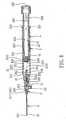
- a conventional intravenous catheter inserting device 1is shown to include a tubular needle seat 11 with a hub end 111, a needle cannula 12 secured to the hub end 111, a catheter hub 13 sleeved on the needle seat 11, and a flexible tubular catheter 14 secured to the catheter hub 13.
- the catheter 14 and the needle cannula 12are inserted into the patient' s vein by a health care worker by piercing the patient's vein with a sharp tip of the needle cannula 12 which projects outwardly of the catheter 14..
- the health care workerthen withdraws the needle cannula 12 from the catheter 14 with one hand and, at the same time, applies pressure to the patient' s skin with the other hand, thereby leaving the catheter 14 in the patient's vein.
- a transfusion member(not shown) with medication fluid or an empty barrel is connected to the catheter hub 13 for administering the medication fluid into the patient's vein or for drawing blood.
- the exposed sharp tip of the used needle cannula 12may create a danger of an accidental needle stick.
- blood contaminationmay occur during connection of the catheter hub 13 to the transfusion member or the empty barrel.
- the needle cannular 12lends to be bent during passage of the catheter 14 into the patient's vein.
- the blood in the catheter 14is not visible when the portion of the needle cannula 12 with the notch 121 is inserted into the patient's vein.
- US-A-5,376,071(Henderson ) describes an approved assembly for insertion of an intravenous catheter and a method of insertion which minimizes or eliminates the potential for exposure to blood and other bodily fluids during the use and insertion of an intravenous catheter.
- An intravenous catheter hubhas a side opening directly connected to a port of a multi-port stopcock.
- a modified syringe and hollow-bore needleare attached directly to the base of the catheter and when properly inserted, the needle extend slightly beyond the tip of the catheter. After the needle is inserted into the skin, the syringe is used to generate slight negative pressure so that blood immediately flows into the syringe as soon as a vein is punctured by the needle.
- FR-A-2,675,999(Ferras ) describes a syringe having a needle cannula which can he retractably received in the open forward end of the syringe barrel.
- the syringe plungerhas a cavity extending in the longitudinal direction and containing fluid at a reduced pressure and which is coupled with the needle cannula within the passage of the barrel such that the needle cannula can be retracted into the cavity once the needle cannula is subject to a suction force that arises a result of a pressure difference between the ambient air and the reduced pressure.
- the object of the present inventionis to provide an intravenous catheter inserting device which can prevent accidental, inadvertent contact with a needle cannula after use, and which can prevent contamination of that was drawn with the use of the same.
- the intravenous catheter inserting deviceincludes a catheter hub, a tubular catheter, a barrel, a needle cannula, a tubular needle scat, and a plunger.
- the catheter hubincludes a surrounding tip wall which surrounds a first axis and which confines a through hole, a sleeve wall which has an inner sleeve wall surface that confines an insert hole larger than the through hole, and an intermediate tubular wall which is interposed between the surrounding tip wall and the sleeve wall, which confines a duct communicating the insert hole with the through hole, and which has a communicating port to communicate the duct with ambient air.
- the tubular catheterincludes a proximate segment which is disposed in the through hole and which extends along the first axis to communicate with the duct, and a distal segment which extends from the proximate segment along the first axis to project outwardly of the surrounding tip wall.
- the barrelhas outer and inner surrounding barrel wall surfaces opposite to each other and surrounding a second axis.
- the inner surrounding barrel wall surfaceconfines a passage which has opposite open forward and rearward ends, and includes a larger-diameter segment and a smaller-diameter segment that confine rear and front passageways, respectively, and that are disposed proximate to the open rearward and forward ends, respectively, to form a surrounding shoulder portion.
- the outer surrounding barrel wall surfacehas a front surrounding region which is secured relative to the inner sleeve wall surface, thereby resulting in coincidence of the first axis with the second axis.
- the needle cannulaincludes opposite tip and fixed ends and a middle segment interposed therebetween.
- the tubular needle seatis received in the passage, and extends along the second axis.
- the tubular needle seatincludes a hub end which is disposed to secure the fixed end, a surrounding engaged wall which extends from the hub end along the second axis and which confines an axial path to accommodate or communicate with the fixed end, and an anchoring segment which confines an axial through hole to communicate with the passage and which extends outwardly of the front passageway from the surrounding engaged wall.
- the surrounding engaged wallhas an outer engaged wall surface which engages the smaller-diameter segment and which is rotatable relative to the smaller-diameter segment about the second axis between interengaged and released positions, where the surrounding engaged wall is respectively unmovable and movable relative to the smaller-diameter segment along the second axis, respectively.
- the anchoring segmentterminates at an anchoring end which is rotated with the surrounding engaged wall. As such, when the surrounding engaged wall is turned in a clockwise direction from the interengaged position to the released position, the anchoring end can move from a hook-up position that is closer to the surrounding shoulder portion, to a depressed position that is remote from the surrounding shoulder portion.
- the plungeris received in the passage such that in a use position, the plunger is movable along the larger-diameter segment, and such that in a disposal position, the plunger is unmovable along but is rotatable relative to the larger-diameter segment.
- the plungerincludes a plunger body and a seal member.
- the plunger bodyincludes a top end wall disposed to confront the surrounding shoulder portion, and a bottom end wall extending outwardly of the open rearward end to permit movement and rotation of the plunger.
- the top end wallhas an inner peripheral edge portion which surrounds the second axis, and which defines a cavity therein. The cavity extends along the second axis and towards the bottom end wall, and contains fluid at a reduced pressure.
- the seal memberincludes an anchored portion and a sealing portion.
- the anchored portionis disposed to be engageable with the anchoring end such that when the plunger is in the disposal position, and when the surrounding engaged wall is in the interengaged position, rotation of the plunger body in a clockwise direction relative to the larger-diameter segment brings the surrounding engaged wall to turn from the interengaged position to the released position, thereby moving the anchoring end from the hook-up position to the depressed position.
- the sealing portionis sealingly attached to the inner peripheral edge portion along a sealing line so as to trap the fluid in the cavity. Movement of the anchoring end from the hook-up position to the depressed position results in depression of the anchored portion so as to rip the sealing line, thereby releasing the seal member from the plunger body.
- the tubular needle seat together with the needle cannulacan be pulled by the seal member which is suctioned into the cavity due to a pressure difference between the reduced pressure and the ambient air that is introduced through the communicating port, thereby permitting retraction of the needle cannula from the tubular catheter into the cavity.
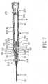
- the first preferred embodiment of an intravenous catheter inserting deviceis shown to comprise a catheter hub 5, a tubular catheter 6, a barrel 2, a needle assembly 3, and a plunger 4.
- the catheter hub 5includes a surrounding tip wall 512, a sleeve wall 511 which is opposite to the surrounding tip wall 512 along a first axis, and an intermediate tubular wall 51 which is interposed between the surrounding tip wall 512 and the sleeve wall 511.
- the surrounding tip wall 512surrounds the first axis, and confines a through hole 516 which extends along the first axis.
- the sleeve wall 511has an inner sleeve wall surface which surrounds the first axis and which confines an insert hole 517 larger than the through hole 516.
- the intermediate tubular wall 51has an inner tubular wall surface that confines a duct 513 which communicates the insert hole 517 with the through hole 516, and an outer tubular wall surface opposite to the inner tubular wall surface in radial directions.
- the intermediate tubular wall 51has a communicating port 514 which extends radially through the inner and outer tubular wall surfaces to communicate the duct 513 with ambient air.
- a plug 52is disposed to close the communicating port 514, as shown in Fig. 4 .
- the inner tubular wall surface of the intermediate tubular wall 51forms a retaining shoulder 518 with the surrounding tip wall 512.
- the retaining shoulder 518confronts the duct 513 along the first axis.
- the tubular catheter 6includes a proximate segment 61 which is disposed in the through hole 516 and which extends along the first axis to communicate with the duct 517 and to project outwardly of the through hole 516, and a distal segment 62 which extends from the proximate segment 61 along the first axis to project outwardly of the surrounding tip wall 512.
- the proximate segment 61terminates at a flange portion 611 which abuts against and which is retained at the retaining shoulder 518.
- the barrel 2has outer and inner surrounding barrel wall surfaces 221,222 opposite to each other and surrounding a second axis.
- the inner surrounding barrel wall surface 222confines a passage 21 which has open forward and rearward ends 223,224 that are disposed opposite to each other in a longitudinal direction parallel to the second axis, and includes a larger-diameter segment 212 and a smaller-diameter segment 211 which confine rear and front passageways, respectively, and which are disposed proximate to the open rearward and forward ends 224,223, respectively, to form a surrounding shoulder portion 213 between the larger-diameter segment 212 and the smaller-diameter segment 211.
- the outer surrounding barrel wall surface 221has a front surrounding region 2211 which is proximate to the open forward end 223, and which is insertable into the insert hole 517 so as to abut against the inner sleeve wall surface of the sleeve wall 511, thereby resulting in coincidence of the first axis with the second axis.
- a first female screw thread segment 225includes a plurality of angularly displaced ribs, and is disposed on the larger-diameter segment 212 adjacent to the open rearward end 224.
- a second female screw thread segment 226 in the form of a spiral grooveis disposed on the smaller-diameter segment 211 adjacent to the surrounding shoulder portion 213.
- the needle assembly 3includes a needle cannula 32 and a tubular needle seat 31.
- the needle cannula 32includes tip and fixed ends 321,322 opposite to each other, and a middle segment 323 interposed between the tip and fixed ends 321,322.
- the tubular needle seat 31is made of a light transmissible material, is received in the passage 21, and extends along the second axis.
- the tubular needle seat 31includes a hub end 313 which is disposed to secure the fixed end 322 of the needle cannula 32, and a surrounding engaged wall 311 which extends from the hub end 313 along the second axis, and which confines an axial path to accommodate or communicate with the fixed end 322 of the needle cannula 32.
- the surrounding engaged wall 311has an outer engaged wall surface which is provided with a (second) male screw thread segment 314 that includes a plurality of angularly displaced ribs and that surrounds the second axis to threadedly engage the second female screw thread segment 226 in an interengaged position, whereby the surrounding engaged wall 311 of the tubular needle seat 31 is unmovable relative to the smaller-diameter segment 211 along the second axis.
- a (second) male screw thread segment 314that includes a plurality of angularly displaced ribs and that surrounds the second axis to threadedly engage the second female screw thread segment 226 in an interengaged position, whereby the surrounding engaged wall 311 of the tubular needle seat 31 is unmovable relative to the smaller-diameter segment 211 along the second axis.
- the tubular needle seat 31further includes an anchoring segment 312 which confines an axial through hole 3121 to communicate with the passage 21, and which extends outwardly of the front passageway of the smaller-diameter segment 211 from the surrounding engaged wall 311 to terminate at an anchoring end 3122.
- a (third) male screw thread segment 315includes a plurality of ribs and is disposed on the anchoring end 3122.
- the plunger 4is received in the passage 21 such that in a use position, as shown in Fig. 4 , the plunger 4 is movable along the larger-diameter segment 212 in the longitudinal direction, and such that in a disposal position, as shown in Fig. 5 , the plunger 4 is unmovable along, but is rotatable relative to the larger-diameter segment 212.
- the plunger 4includes a plunger body 42 and a seal member 43.
- the plunger body 42includes a top end wall 421 which is disposed to confront the surrounding shoulder portion 213, and a bottom end wall 422 opposite to the top end wall 421 in the longitudinal direction.
- the bottom end wall 422extends outwardly of the open rearward end 224 to permit movement and rotation of the plunger 4.
- the top end wall 421has an inner peripheral edge portion 424 which surrounds the second axis, and which defines a cavity 41 therein.
- the cavity 41extends along the second axis and towards the bottom end wall 422, and contains fluid at a reduced pressure.
- the plunger body 42has an outer plunger wall surface 423 which surrounds the second axis.
- a first male screw thread segment 425includes a plurality of ribs, and is disposed on the outer plunger wall surface 423.
- a catcher portion 426is disposed on the inner peripheral edge portion 424 proximate to the bottom end wall 422.
- the seal member 43is formed from an elastomeric material, and includes an anchored portion 432 and a sealing portion 434.
- the anchored portion 432has an inner surrounding wall which extends along the second axis to confine a recess 431 that is configured to accommodate and to be engageable with the anchoring end 3122 of the anchoring segment 312.
- the inner surrounding wallis formed with a third female screw thread segment 433 that is in the form of a spiral groove.
- a surrounding protrusion 4241is disposed to extend from the inner peripheral edge portion 424 in a radial direction and towards the second axis so as to be in frictional contact with the sealing portion 434, thereby establishing a sealing line to trap the fluid in the cavity 41.
- a health care workerholds the barrel 2 with one hand to insert the tip end 321 of the needle cannula 32 and the distal segment 62 of the tubular catheter 6 into the patient's vein.
- the anchoring segment 312 of the tubular needle seat 31is light transmissible and has a convex surface 316 to provide a magnified view of the blood flowing through the axial through hole 3121.
- the plug 52 shown in Fig. 4is removed from the communicating port 514 so as to communicate the duct 513 with the ambient air.
- the plunger 4is pressed forwardly to contact the tubular needle seat 31 (see Fig. 5 ) .
- the first male and female screw thread segments 425,225By means of the first male and female screw thread segments 425,225, displacement of the plunger 4 along the larger-diameter segment 212 is restrained, whereas rotation of the plunger 4 in a clockwise direction relative to the larger-diameter segment 212 is permitted.
- the plunger 4is screwed toward the open forward end 223.
- the seal member 43is rotated relative to the tubular needle seat 31, and the anchored portion 432 of the seal member 43 is brought to engage the anchoring end 3122 by virtue of the engagement of the third male and female screw thread segments 315,433, as shown in Fig. 6 .
- the tubular needle seat 31is rotatable together with the seal member 43.
- the tubular needle seat 31 together with the needle cannula 32can be pulled by the seal member 43 that is suctioned into the cavity 41 due to the pressure difference between the reduced pressure and the ambient air that is introduced through the communicating port 514, thereby permitting retraction of the needle cannula 32 from the tubular catheter 6 into the cavity 41, as shown in Fig. 8 .
- the tubular needle seat 31 as well as the needle cannula 32can be prevented from impinging upon the bottom end wall 422.
- a blood collecting member 7is connected to the catheter hub 5.
- the blood collecting member 7includes a surrounding wall 72 which confines a receiving space 71 and which has an introduced port 73 communicating with the receiving space 71.
- a first connecting flexible tube 81is disposed to interconnect the introduced port 73 and the communicating port 514. The blood can flow into the blood collecting member 7 through the tubular catheter 6, the duct 513, and the first connecting flexible tube 81 without the need to pull the plunger body 42, thereby preventing the health care worker from coming into contact with the blood.
- the second preferred embodiment of the intravenous catheter inserting deviceis shown to be similar to the previous embodiment in construction.
- the inner sleeve wall surface of the sleeve wall 511 of the catheter hub 5has a reentry port 515 which extends radially through the sleeve wall 511 to communicate with the insert hole 517, and which is opposite to the communicating port 514 relative to a boundary area 519.
- the intravenous catheter inserting device of this embodimentfurther includes a barrier member 54 and a tubular insert 53.
- the barrier member 54is formed from an elastomeric material, such as a rubber.
- the tubular insert 53has a front neck end 534 which is connected to the barrier member 54 and which confines a through way 531 along the first axis, and a rear flared end 532 which extends from the front neck end 534 along the first axis, and which has an inner abutted surface 536.
- the inner abutted surface 536surrounds the first axis, and confines a fluid path 535 which extends to communicate with the reentry port 515.
- the blood collecting member 7has an air outlet 74 spaced apart from the introduced port 73.
- a second connecting flexible tube 82is disposed to interconnect the air outlet 74 and the reentry port 515.
- the barrier member 54In assembly, the barrier member 54, on which the front neck end 534 is connected, is engaged with the inner sleeve wall surface of the sleeve wall 511 of the catheter hub 5 at the boundary area 519.
- the front surrounding region 2211 of the barrel 2is engaged with the inner abutted surface 536 of the tubular insert 53, thereby aligning the through way 531 with the passage 21 of the barrel 2.
- the needle cannula 32(not shown in Fig. 10 ) extends through the through way 531, a slit in the barrier member 54, the duct 513, and the tubular catheter 6.
- the health care workercan pull the plunger body 42 rearwardly so as to introduce an air flow from the air outlet 74 through the second connecting flexible tube 82, the reentry port 515, and the fluid path 535 to the passage 21 of the barrel 2, thereby facilitating blood flow into the blood collecting member 7.
- the third preferred embodiment of the intravenous catheter inserting deviceis shown to be similar to the first preferred embodiment in construction.
- the duct 513 of the catheter hub 5is communicated with the passage 21 of the barrel 2 through a tubular insert 55.
- the tubular insert 55has a front neck end 554 which is connected to a barrier member 54 and which confines a through way along the axis, and a rear flared end 552 which extends from the front neck end 554 along the first axis.
- the rear flared end 552has an inner abutted surface which surrounds the first axis and which confines a fluid path 551, and a reentry port 555 which extends radially therethrough to communicate with the fluid path 551.
- the front surrounding region 2211 of the barrel 2engages the inner abutted surface of the tubular insert 55.
- the slit in the barrier member 54is closed by means of its elastomeric material property.
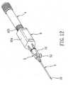
- the fourth preferred embodiment of the intravenous catheter inserting deviceis shown to include a barrel 9 which is shorter than that of the previous embodiments.
- the barrel 9also has an inner surrounding barrel wall surface 936 which includes smaller-diameter and larger-diameter segments 91,92 and which confines a passage having open forward and rearward ends 931,932.
- the sleeve wall 511 of the catheter hub 5is brought to engage the open forward end 931.
- the larger-diameter segment 92has a male screw thread segment 935 so as to threadedly engage the female screw thread segment 425 formed on the outer plunger wall surface of the plunger 4.
- the health care workercan grasp the outer surrounding barrel wall surface 934 and insert the needle cannula 32, as well as the tubular catheter 6, into the patient's vein such that blood can flow into the barrel 9. Then, in the same manner described hereinabove, the needle cannula 32 can be retracted into the cavity 41 of the plunger 4 for safe disposal.
- a tip protector 33is disposed to shield the needle cannula 32 and the catheter hub 5, and has a larger open end 331 for insertion of a front half portion of the barrel 9.
- a sleeve tube 34is disposed to shield the plunger 4, and has an open end 341 for insertion of a rear half portion of the barrel 9.
- the intravenous catheter inserting device of this inventionhas the following advantages:
Landscapes
- Health & Medical Sciences (AREA)
- Life Sciences & Earth Sciences (AREA)
- Hematology (AREA)
- Animal Behavior & Ethology (AREA)
- Engineering & Computer Science (AREA)
- Anesthesiology (AREA)
- Biomedical Technology (AREA)
- Heart & Thoracic Surgery (AREA)
- Biophysics (AREA)
- Pulmonology (AREA)
- General Health & Medical Sciences (AREA)
- Public Health (AREA)
- Veterinary Medicine (AREA)
- Infusion, Injection, And Reservoir Apparatuses (AREA)
- Media Introduction/Drainage Providing Device (AREA)
- Thermotherapy And Cooling Therapy Devices (AREA)
Abstract
Description
- This invention relates to an intravenous catheter inserting device, more particularly to an intravenous catheter inserting device which enables a needle cannula to be retracted within a plunger cavity having a reduced pressure therein.
- Intravenous catheter inserting devices are generally used to administer medication fluid into or draw blood from a patient's vein. Referring to
Figs. 1 and2 , a conventional intravenouscatheter inserting device 1 is shown to include a tubular needle seat 11 with ahub end 111, aneedle cannula 12 secured to thehub end 111, acatheter hub 13 sleeved on the needle seat 11, and a flexibletubular catheter 14 secured to thecatheter hub 13. In use, thecatheter 14 and theneedle cannula 12 are inserted into the patient' s vein by a health care worker by piercing the patient's vein with a sharp tip of theneedle cannula 12 which projects outwardly of thecatheter 14.. The health care worker then withdraws theneedle cannula 12 from thecatheter 14 with one hand and, at the same time, applies pressure to the patient' s skin with the other hand, thereby leaving thecatheter 14 in the patient's vein. Subsequently, a transfusion member (not shown) with medication fluid or an empty barrel is connected to thecatheter hub 13 for administering the medication fluid into the patient's vein or for drawing blood. At this time, as the health care worker must place theused needle cannula 12 and the needle seat 11 on a tray (not shown) nearby, the exposed sharp tip of the usedneedle cannula 12 may create a danger of an accidental needle stick. Moreover, blood contamination may occur during connection of thecatheter hub 13 to the transfusion member or the empty barrel. - Referring to
Fig. 2 , during the insertion procedure, the now of blood into thecatheter 14 through anotch 121 in theneedle cannula 12 can be observed through thetranslucent catheter 14. However, due to the presence of thenotch 121, theneedle cannular 12 lends to be bent during passage of thecatheter 14 into the patient's vein. In addition, the blood in thecatheter 14 is not visible when the portion of theneedle cannula 12 with thenotch 121 is inserted into the patient's vein. US-A-5,376,071 (Henderson ) describes an approved assembly for insertion of an intravenous catheter and a method of insertion which minimizes or eliminates the potential for exposure to blood and other bodily fluids during the use and insertion of an intravenous catheter. An intravenous catheter hub has a side opening directly connected to a port of a multi-port stopcock. A modified syringe and hollow-bore needle are attached directly to the base of the catheter and when properly inserted, the needle extend slightly beyond the tip of the catheter. After the needle is inserted into the skin, the syringe is used to generate slight negative pressure so that blood immediately flows into the syringe as soon as a vein is punctured by the needle.FR-A-2,675,999 (Ferras - The object of the present invention is to provide an intravenous catheter inserting device which can prevent accidental, inadvertent contact with a needle cannula after use, and which can prevent contamination of that was drawn with the use of the same.
- According to this invention, the intravenous catheter inserting device includes a catheter hub, a tubular catheter, a barrel, a needle cannula, a tubular needle scat, and a plunger.
- The catheter hub includes a surrounding tip wall which surrounds a first axis and which confines a through hole, a sleeve wall which has an inner sleeve wall surface that confines an insert hole larger than the through hole, and an intermediate tubular wall which is interposed between the surrounding tip wall and the sleeve wall, which confines a duct communicating the insert hole with the through hole, and which has a communicating port to communicate the duct with ambient air.
- The tubular catheter includes a proximate segment which is disposed in the through hole and which extends along the first axis to communicate with the duct, and a distal segment which extends from the proximate segment along the first axis to project outwardly of the surrounding tip wall.
- The barrel has outer and inner surrounding barrel wall surfaces opposite to each other and surrounding a second axis. The inner surrounding barrel wall surface confines a passage which has opposite open forward and rearward ends, and includes a larger-diameter segment and a smaller-diameter segment that confine rear and front passageways, respectively, and that are disposed proximate to the open rearward and forward ends, respectively, to form a surrounding shoulder portion. The outer surrounding barrel wall surface has a front surrounding region which is secured relative to the inner sleeve wall surface, thereby resulting in coincidence of the first axis with the second axis.
- The needle cannula includes opposite tip and fixed ends and a middle segment interposed therebetween.
- The tubular needle seat is received in the passage, and extends along the second axis. The tubular needle seat includes a hub end which is disposed to secure the fixed end, a surrounding engaged wall which extends from the hub end along the second axis and which confines an axial path to accommodate or communicate with the fixed end, and an anchoring segment which confines an axial through hole to communicate with the passage and which extends outwardly of the front passageway from the surrounding engaged wall. The surrounding engaged wall has an outer engaged wall surface which engages the smaller-diameter segment and which is rotatable relative to the smaller-diameter segment about the second axis between interengaged and released positions, where the surrounding engaged wall is respectively unmovable and movable relative to the smaller-diameter segment along the second axis, respectively. The anchoring segment terminates at an anchoring end which is rotated with the surrounding engaged wall. As such, when the surrounding engaged wall is turned in a clockwise direction from the interengaged position to the released position, the anchoring end can move from a hook-up position that is closer to the surrounding shoulder portion, to a depressed position that is remote from the surrounding shoulder portion.
- The plunger is received in the passage such that in a use position, the plunger is movable along the larger-diameter segment, and such that in a disposal position, the plunger is unmovable along but is rotatable relative to the larger-diameter segment. The plunger includes a plunger body and a seal member.
- The plunger body includes a top end wall disposed to confront the surrounding shoulder portion, and a bottom end wall extending outwardly of the open rearward end to permit movement and rotation of the plunger. The top end wall has an inner peripheral edge portion which surrounds the second axis, and which defines a cavity therein. The cavity extends along the second axis and towards the bottom end wall, and contains fluid at a reduced pressure.
- The seal member includes an anchored portion and a sealing portion. The anchored portion is disposed to be engageable with the anchoring end such that when the plunger is in the disposal position, and when the surrounding engaged wall is in the interengaged position, rotation of the plunger body in a clockwise direction relative to the larger-diameter segment brings the surrounding engaged wall to turn from the interengaged position to the released position, thereby moving the anchoring end from the hook-up position to the depressed position. The sealing portion is sealingly attached to the inner peripheral edge portion along a sealing line so as to trap the fluid in the cavity. Movement of the anchoring end from the hook-up position to the depressed position results in depression of the anchored portion so as to rip the sealing line, thereby releasing the seal member from the plunger body. Hence, the tubular needle seat together with the needle cannula can be pulled by the seal member which is suctioned into the cavity due to a pressure difference between the reduced pressure and the ambient air that is introduced through the communicating port, thereby permitting retraction of the needle cannula from the tubular catheter into the cavity.
- Other features and advantages of the present invention will become apparent in the following detailed description of the preferred embodiments of the invention, with reference to the accompanying drawings, in which:
Fig. 1 is a perspective view of a conventional intravenous catheter inserting device;Fig. 2 is a partly sectional schematic view illustrating a needle cannula sleeved over by a catheter of the conventional intravenous catheter inserting device;Fig. 3 is an exploded sectional view of the first preferred embodiment of an intravenous catheter inserting device according to this invention;Fig. 4 is a sectional view of the first preferred embodiment in a state of use;Fig. 5 is a sectional view of the first preferred embodiment in a state where a seal member is in contact with a tubular needle seat;Fig. 6 is a sectional view of the first preferred embodiment in a state where the seal member engages the tubular needle seat;Fig. 7 is a sectional view of the first preferred embodiment in a state where the seal member is disengaged from a plunger body;Fig. 8 is a sectional view of the first preferred embodiment in a state where the tubular needle seat and a needle cannula are retracted into the plunger body;Fig. 9 is a fragmentary sectional view of the first preferred embodiment in another state of use;Fig. 10 is a fragmentary sectional view of the second preferred embodiment of an intravenous catheter inserting device according to this invention;Fig. 11 is a sectional view of the third preferred embodiment of an intravenous catheter inserting device according to this invention;Fig. 12 is a perspective view of the fourth preferred embodiment of an intravenous catheter inserting device according to this invention; andFig. 13 is a sectional view of the fourth preferred embodiment of the intravenous catheter inserting device.- Before the present invention is described in greater detail, it should be noted that same reference numerals have been used to denote like elements throughout the specification.
- Referring to
Figs. 3 and4 , the first preferred embodiment of an intravenous catheter inserting device according to the present invention is shown to comprise acatheter hub 5, atubular catheter 6, abarrel 2, aneedle assembly 3, and aplunger 4. - The
catheter hub 5 includes a surroundingtip wall 512, asleeve wall 511 which is opposite to the surroundingtip wall 512 along a first axis, and an intermediatetubular wall 51 which is interposed between the surroundingtip wall 512 and thesleeve wall 511. - The surrounding
tip wall 512 surrounds the first axis, and confines a throughhole 516 which extends along the first axis. Thesleeve wall 511 has an inner sleeve wall surface which surrounds the first axis and which confines aninsert hole 517 larger than the throughhole 516. The intermediatetubular wall 51 has an inner tubular wall surface that confines aduct 513 which communicates theinsert hole 517 with the throughhole 516, and an outer tubular wall surface opposite to the inner tubular wall surface in radial directions. In addition, the intermediatetubular wall 51 has a communicatingport 514 which extends radially through the inner and outer tubular wall surfaces to communicate theduct 513 with ambient air. Aplug 52 is disposed to close the communicatingport 514, as shown inFig. 4 . The inner tubular wall surface of the intermediatetubular wall 51 forms aretaining shoulder 518 with the surroundingtip wall 512. The retainingshoulder 518 confronts theduct 513 along the first axis. - The
tubular catheter 6 includes aproximate segment 61 which is disposed in the throughhole 516 and which extends along the first axis to communicate with theduct 517 and to project outwardly of the throughhole 516, and adistal segment 62 which extends from theproximate segment 61 along the first axis to project outwardly of the surroundingtip wall 512. Theproximate segment 61 terminates at aflange portion 611 which abuts against and which is retained at the retainingshoulder 518. - The
barrel 2 has outer and inner surrounding barrel wall surfaces 221,222 opposite to each other and surrounding a second axis. The inner surroundingbarrel wall surface 222 confines apassage 21 which has open forward and rearward ends 223,224 that are disposed opposite to each other in a longitudinal direction parallel to the second axis, and includes a larger-diameter segment 212 and a smaller-diameter segment 211 which confine rear and front passageways, respectively, and which are disposed proximate to the open rearward and forward ends 224,223, respectively, to form asurrounding shoulder portion 213 between the larger-diameter segment 212 and the smaller-diameter segment 211. The outer surroundingbarrel wall surface 221 has a frontsurrounding region 2211 which is proximate to the openforward end 223, and which is insertable into theinsert hole 517 so as to abut against the inner sleeve wall surface of thesleeve wall 511, thereby resulting in coincidence of the first axis with the second axis. A first femalescrew thread segment 225 includes a plurality of angularly displaced ribs, and is disposed on the larger-diameter segment 212 adjacent to the openrearward end 224. A second femalescrew thread segment 226 in the form of a spiral groove is disposed on the smaller-diameter segment 211 adjacent to thesurrounding shoulder portion 213. - The
needle assembly 3 includes aneedle cannula 32 and atubular needle seat 31. - The
needle cannula 32 includes tip and fixed ends 321,322 opposite to each other, and amiddle segment 323 interposed between the tip and fixed ends 321,322. - The
tubular needle seat 31 is made of a light transmissible material, is received in thepassage 21, and extends along the second axis. Thetubular needle seat 31 includes ahub end 313 which is disposed to secure thefixed end 322 of theneedle cannula 32, and a surrounding engagedwall 311 which extends from thehub end 313 along the second axis, and which confines an axial path to accommodate or communicate with thefixed end 322 of theneedle cannula 32. The surrounding engagedwall 311 has an outer engaged wall surface which is provided with a (second) malescrew thread segment 314 that includes a plurality of angularly displaced ribs and that surrounds the second axis to threadedly engage the second femalescrew thread segment 226 in an interengaged position, whereby the surrounding engagedwall 311 of thetubular needle seat 31 is unmovable relative to the smaller-diameter segment 211 along the second axis. - The
tubular needle seat 31 further includes ananchoring segment 312 which confines an axial throughhole 3121 to communicate with thepassage 21, and which extends outwardly of the front passageway of the smaller-diameter segment 211 from the surrounding engagedwall 311 to terminate at ananchoring end 3122. A (third) malescrew thread segment 315 includes a plurality of ribs and is disposed on the anchoringend 3122. - The
plunger 4 is received in thepassage 21 such that in a use position, as shown inFig. 4 , theplunger 4 is movable along the larger-diameter segment 212 in the longitudinal direction, and such that in a disposal position, as shown inFig. 5 , theplunger 4 is unmovable along, but is rotatable relative to the larger-diameter segment 212. Theplunger 4 includes aplunger body 42 and aseal member 43. - The
plunger body 42 includes atop end wall 421 which is disposed to confront thesurrounding shoulder portion 213, and abottom end wall 422 opposite to thetop end wall 421 in the longitudinal direction. Thebottom end wall 422 extends outwardly of the openrearward end 224 to permit movement and rotation of theplunger 4. Thetop end wall 421 has an innerperipheral edge portion 424 which surrounds the second axis, and which defines acavity 41 therein. Thecavity 41 extends along the second axis and towards thebottom end wall 422, and contains fluid at a reduced pressure. In addition, theplunger body 42 has an outerplunger wall surface 423 which surrounds the second axis. A first malescrew thread segment 425 includes a plurality of ribs, and is disposed on the outerplunger wall surface 423. Acatcher portion 426 is disposed on the innerperipheral edge portion 424 proximate to thebottom end wall 422. - The
seal member 43 is formed from an elastomeric material, and includes an anchoredportion 432 and a sealingportion 434. The anchoredportion 432 has an inner surrounding wall which extends along the second axis to confine arecess 431 that is configured to accommodate and to be engageable with the anchoringend 3122 of theanchoring segment 312. The inner surrounding wall is formed with a third femalescrew thread segment 433 that is in the form of a spiral groove. Referring toFig. 4 , a surroundingprotrusion 4241 is disposed to extend from the innerperipheral edge portion 424 in a radial direction and towards the second axis so as to be in frictional contact with the sealingportion 434, thereby establishing a sealing line to trap the fluid in thecavity 41. - In use, as shown in
Fig. 4 , a health care worker holds thebarrel 2 with one hand to insert thetip end 321 of theneedle cannula 32 and thedistal segment 62 of thetubular catheter 6 into the patient's vein. Theanchoring segment 312 of thetubular needle seat 31 is light transmissible and has aconvex surface 316 to provide a magnified view of the blood flowing through the axial throughhole 3121. Once the health care worker notes that the blood does not flow into theanchoring segment 312, he/she can pull theplunger 4 slightly rearward to draw the blood until the blood is visible through theanchoring segment 312 so as to confirm correct insertion of thetubular catheter 6 into the patient's vein. - Referring to
Figs. 5 and6 , theplug 52 shown inFig. 4 is removed from the communicatingport 514 so as to communicate theduct 513 with the ambient air. Theplunger 4 is pressed forwardly to contact the tubular needle seat 31 (seeFig. 5 ) . By means of the first male and female screw thread segments 425,225, displacement of theplunger 4 along the larger-diameter segment 212 is restrained, whereas rotation of theplunger 4 in a clockwise direction relative to the larger-diameter segment 212 is permitted. Theplunger 4 is screwed toward the openforward end 223. By the screw movement of theplunger 4, theseal member 43 is rotated relative to thetubular needle seat 31, and the anchoredportion 432 of theseal member 43 is brought to engage theanchoring end 3122 by virtue of the engagement of the third male and female screw thread segments 315,433, as shown inFig. 6 . Thus, thetubular needle seat 31 is rotatable together with theseal member 43. - Subsequently, as shown in
Fig. 7 , when theplunger 4 is further rotated in the clockwise direction relative to the larger-diameter segment 212 such that thetubular needle seat 31 is rotated to turn the second malescrew thread segment 314 about the second axis to a released position for removal from the second femalescrew thread segment 226, the surrounding engagedwall 311 of thetubular needle seat 31 is moved relative to the smaller-diameter segment 211 along the second axis towards the openrearward end 224. The anchoringend 3122 is also rotated to move from a hook-up position that is closer to thesurrounding shoulder portion 213 to a depressed position that is remote from the surroundingshoulder portion 213. At the same time, movement of the anchoringend 3122 from the hook-up position to the depressed position will result in depression of the anchoredportion 432 so as to rip the sealing line, thereby releasing theseal member 43 from theplunger body 42. As such, thetubular needle seat 31 together with theneedle cannula 32 can be pulled by theseal member 43 that is suctioned into thecavity 41 due to the pressure difference between the reduced pressure and the ambient air that is introduced through the communicatingport 514, thereby permitting retraction of theneedle cannula 32 from thetubular catheter 6 into thecavity 41, as shown inFig. 8 . Furthermore, by means of thecatcher portion 426, thetubular needle seat 31 as well as theneedle cannula 32 can be prevented from impinging upon thebottom end wall 422. - Therefore, in use, the health care worker can close the communicating
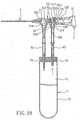
port 514 with theplug 52, and then pull theplunger body 42, in which theseal member 43 and theneedle assembly 3 are left, towards the openrearward end 224 so as to draw a smaller amount of blood into thepassage 21 of thebarrel 2 through thetubular catheter 6. Referring toFig. 9 , when the health care worker needs to draw a larger amount of blood, ablood collecting member 7 is connected to thecatheter hub 5. Theblood collecting member 7 includes a surroundingwall 72 which confines a receivingspace 71 and which has an introducedport 73 communicating with the receivingspace 71. A first connectingflexible tube 81 is disposed to interconnect the introducedport 73 and the communicatingport 514. The blood can flow into theblood collecting member 7 through thetubular catheter 6, theduct 513, and the first connectingflexible tube 81 without the need to pull theplunger body 42, thereby preventing the health care worker from coming into contact with the blood. - Alternatively, referring to
Fig. 10 , the second preferred embodiment of the intravenous catheter inserting device according to this invention is shown to be similar to the previous embodiment in construction. In addition to the component parts of the previous embodiment, the inner sleeve wall surface of thesleeve wall 511 of thecatheter hub 5 has areentry port 515 which extends radially through thesleeve wall 511 to communicate with theinsert hole 517, and which is opposite to the communicatingport 514 relative to aboundary area 519. Moreover, the intravenous catheter inserting device of this embodiment further includes abarrier member 54 and atubular insert 53. Thebarrier member 54 is formed from an elastomeric material, such as a rubber. Thetubular insert 53 has afront neck end 534 which is connected to thebarrier member 54 and which confines a throughway 531 along the first axis, and a rear flaredend 532 which extends from thefront neck end 534 along the first axis, and which has an inner abuttedsurface 536. The inner abuttedsurface 536 surrounds the first axis, and confines afluid path 535 which extends to communicate with thereentry port 515. Furthermore, theblood collecting member 7 has an air outlet 74 spaced apart from the introducedport 73. A second connectingflexible tube 82 is disposed to interconnect the air outlet 74 and thereentry port 515. In assembly, thebarrier member 54, on which thefront neck end 534 is connected, is engaged with the inner sleeve wall surface of thesleeve wall 511 of thecatheter hub 5 at theboundary area 519. The frontsurrounding region 2211 of thebarrel 2 is engaged with the inner abuttedsurface 536 of thetubular insert 53, thereby aligning the throughway 531 with thepassage 21 of thebarrel 2. The needle cannula 32 (not shown inFig. 10 ) extends through the throughway 531, a slit in thebarrier member 54, theduct 513, and thetubular catheter 6. After the used needle assembly 3 (not shown inFig. 10 ) has been retracted into the plunger body (not shown inFig. 10 ) in the same manner as described above, the slit in thebarrier member 54 is closed by means of its elastomeric material property. - As such, due to the arrangement of the
barrier member 54, once it is noted that blood cannot flow into theblood collecting member 7, the health care worker can pull theplunger body 42 rearwardly so as to introduce an air flow from the air outlet 74 through the second connectingflexible tube 82, thereentry port 515, and thefluid path 535 to thepassage 21 of thebarrel 2, thereby facilitating blood flow into theblood collecting member 7. - Alternatively, referring to
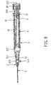
Fig. 11 , the third preferred embodiment of the intravenous catheter inserting device according to this invention is shown to be similar to the first preferred embodiment in construction. Theduct 513 of thecatheter hub 5 is communicated with thepassage 21 of thebarrel 2 through atubular insert 55. Thetubular insert 55 has afront neck end 554 which is connected to abarrier member 54 and which confines a through way along the axis, and a rear flaredend 552 which extends from thefront neck end 554 along the first axis. The rear flaredend 552 has an inner abutted surface which surrounds the first axis and which confines afluid path 551, and areentry port 555 which extends radially therethrough to communicate with thefluid path 551. The frontsurrounding region 2211 of thebarrel 2 engages the inner abutted surface of thetubular insert 55. As such, in the same manner as that of the second preferred embodiment, after the usedneedle assembly 3 has been retracted into theplunger body 42, the slit in thebarrier member 54 is closed by means of its elastomeric material property. - Referring to
Figs. 12 and13 , the fourth preferred embodiment of the intravenous catheter inserting device according to this invention is shown to include abarrel 9 which is shorter than that of the previous embodiments. Thebarrel 9 also has an inner surroundingbarrel wall surface 936 which includes smaller-diameter and larger-diameter segments sleeve wall 511 of thecatheter hub 5 is brought to engage the openforward end 931. The larger-diameter segment 92 has a malescrew thread segment 935 so as to threadedly engage the femalescrew thread segment 425 formed on the outer plunger wall surface of theplunger 4. As such, in use, the health care worker can grasp the outer surroundingbarrel wall surface 934 and insert theneedle cannula 32, as well as thetubular catheter 6, into the patient's vein such that blood can flow into thebarrel 9. Then, in the same manner described hereinabove, theneedle cannula 32 can be retracted into thecavity 41 of theplunger 4 for safe disposal. - Furthermore, a
tip protector 33 is disposed to shield theneedle cannula 32 and thecatheter hub 5, and has a largeropen end 331 for insertion of a front half portion of thebarrel 9. Asleeve tube 34 is disposed to shield theplunger 4, and has anopen end 341 for insertion of a rear half portion of thebarrel 9. Thus, theneedle cannula 32 and theplunger 4 can be completely shielded by thetip protector 33 and thesleeve tube 34 so as to prevent the health care worker from coming into contact therewith. - As illustrated, the intravenous catheter inserting device of this invention has the following advantages:
- 1. After insertion of the
needle cannula 32, by rotating theplunger body 42 in the clockwise direction relative to the larger-diameter segment 212, the usedneedle assembly 3 can be retracted into thecavity 41 of theplunger body 42, thereby facilitating safe disposal of the intravenous catheter inserting device. - 2. Since the
anchoring segment 312 of thetubular needle seat 31 is light-transmissible and has theconvex surface 316, blood flowing through the axial throughhole 3121 is visible to the health care worker in a magnified state. - 3. After the used
needle assembly 3 has been retracted into thecavity 41, the health care worker can directly pull theplunger body 42 for drawing blood into thepassage 21 or theblood collecting member 7 without the need to remove thebarrel 2 and thecatheter hub 5, thereby reducing the possibility of the health care worker coming into contact with blood.
Claims (14)
- An intravenous catheter inserting device,characterized by:a catheter hub (5) including
a surrounding tip wall (512) which surrounds a first axis, and which confines a through hole (516) extending along the first axis,
a sleeve wall (511) which is opposite to said surrounding tip wall (512) along the first axis, and which has an inner sleeve wall surface that surrounds the first axis, and that confines an insert hole (517) larger than said through hole (516), and
an intermediate tubular wall (51) which is interposed between said surrounding tip wall (512) and said sleeve wall (511), which confines a duct (513) communicating said insert hole (517) with said through hole (516), and which has a communicating port (514) extending therethrough to communicate said duct (513) with ambient air;a tubular catheter (6) including a proximate segment (61) which is disposed in said through hole (516) and which extends along the first axis to communicate with said duct (513), and a distal segment (62) which extends from said proximate segment (61) along the first axis to project outwardly of said surrounding tip wall (512);a barrel (2,9) having outer and inner surrounding barrel wall surfaces (221,222) opposite to each other and surrounding a second axis, said inner surrounding barrel wall surface (222) confining a passage (21) having open forward and rearward ends (223,224,931,932) that are disposed opposite to each other in a longitudinal direction parallel to the second axis, said inner surrounding barrel wall surface (222) including a larger-diameter segment (212, 92) and a smaller-diameter segment (211,91) that confine rear and front passageways, respectively, and that are disposed proximate to said open rearward and forward ends (224, 223, 932, 931), respectively, to form a surrounding shoulder portion (213) between said larger-diameter segment (212,92) and said smaller-diameter segment (211,91), said outer surrounding barrel wall surface (221) having a front surrounding region (2211) which is proximate to said open forward end (223, 931), and which is secured relative to said inner sleeve wall surface, thereby resulting in coincidence of the first axis with the second axis;a needle cannula (32) including tip and fixed ends (321,322) opposite to each other, and a middle segment (323) interposed between said tip and fixed ends (321,322);a tubular needle seat (31) received in said passage (21) and extending along the second axis, said tubular needle seat (31) including
a hub end (313) disposed to secure said fixed end (322),
a surrounding engaged wall (311) which extends from said hub end (313) along the second axis, and which confines an axial path to accommodate or communicate with said fixed end (322), said surrounding engaged wall (311) having an outer engaged wall surface which surrounds the second axis, and which engages and which is rotatable relative to said smaller-diameter segment (211,91) about the second axis between interengaged and released positions, where said surrounding engaged wall (311) is unmovable and movable relative to said smaller-diameter segment (211, 91) along the second axis, respectively, and
an anchoring segment (312) which confines an axial through hole (3121) to communicate with said passage (21), and which extends outwardly of said front passageway from said surrounding engaged wall (311), said anchoring segment (312) terminating at an anchoring end (3122) which is rotated with said surrounding engaged wall (311) to move from a hook-up position that is closer to said surrounding shoulder portion (213), to a depressed position that is remote from said surrounding shoulder portion (213) when said surrounding engaged wall (311) is turned in a clockwise direction from the interengaged position to the released position; anda plunger (4) received in said passage (21) such that in a use position, said plunger (4) is movable along said larger-diameter segment (212,92) in the longitudinal direction, and such that in a disposal position, said plunger (4) is unmovable along but is rotatable relative to the larger-diameter segment (212,92), said plunger (4) including
a plunger body (42) which includes a top end wall (421) disposed to confront said surrounding shoulder portion (213), and a bottom end wall (422) opposite to said top end wall (421) in the longitudinal direction, said bottom end wall (422) extending outwardly of said open rearward end (224,932) to permit movement and rotation of said plunger (4), said top end wall (421) having an inner peripheral edge portion (424) which surrounds the second axis, and which defines a cavity (41) therein, said cavity (41) extending along the second axis and towards said bottom end wall (422) and containing fluid at reduced pressure, anda seal member (43) including
an anchored portion (432) disposed to be engageable with said anchoring end (3122) such that when said plunger (4) is in the disposal position and when said surrounding engaged wall (311) is in the interengaged position, rotation of said plunger body (42) in the clockwise direction relative to said larger-diameter segment (212,92) brings said surrounding engaged wall (311) to turn from the interengaged position to the released position, thereby moving said anchoring end (3122) from the hook-up position to the depressed position, and
a sealing portion (434) which is sealingly attached to said inner peripheral edge portion (424) along a sealing line so as to trap said fluid in said cavity (41), the sealing line being configured such that movement of said anchoring end (3122) from the hook-up position to the depressed position results in depression of said anchored portion (432) so as to rip the sealing line, thereby releasing said seal member (43) from said plunger body (42), so that said tubular needle seat (31) together with said needle cannula (32) will be pulled by said seal member (43) which is suctioned into said cavity (41) due to a pressure difference-between the reduced pressure and the ambient air that is introduced through said communicating port (514), thereby permitting retraction of said needle cannula (32) from said tubular catheter (6) into said cavity (41). - The intravenous catheter inserting device according to Claim 1,characterized in that said front surrounding region (2211) of said outer surrounding barrel wall surface (221) of said barrel (2) is inserted into said insert hole (517) so as to abut against said inner sleeve wall surface of said sleeve wall (511) of said catheter hub (5).
- The intravenous catheter inserting device according to Claim 2,characterized in that said plunger body (42) has an outer plunger wall surface (423) which surrounds the second axis, said intravenous catheter inserting device further comprising first male and female screw thread segments (425,225) respectively disposed on said outer plunger wall surface (423) and said larger-diameter segment (212,92) to restrain said plunger body (42) from displacing along said larger-diameter segment (212, 92) while permitting rotation of said plunger body (42) in a clockwise direction relative to said larger-diameter segment (212,92) in the disposal position.
- The intravenous catheter inserting device according to Claim 3, furthercharacterized by second male and female screw thread segments (314,226) respectively disposed on said outer engaged wall surface and said smaller-diameter segment (211,91) to permit rotation of said outer engaged wall surface relative to said smaller-diameter segment (211,91).
- The intravenous catheter inserting device according to Claim 4,characterized in that said anchoring segment (312) is made of a material that is light transmissible so as to permit viewing of liquid, flowing through said axial through hole (3121).
- The intravenous catheter inserting device according to Claim 5,characterized in that said anchoring segment (312) is configured in such a manner so as to provide a magnified view of blood in said axial through hole (3121).
- The intravenous catheter inserting device according to Claim 6,characterized in that said seal member (43) is formed from an elastomeric material.
- The intravenous catheter inserting device according to Claim 7,characterized in that said anchored portion (432) has an inner surrounding wall which extends along the second axis to confine a recess (431) that is configured to accommodate said anchoring end (3122), said intravenous catheter inserting device further comprising third male and female screw thread segments (315,433) disposed respectively on said anchoring end (3122) and said inner surrounding wall so as to permit said anchored portion (432) to be brought to engage with said anchoring end (3122) by virtue of rotation of said third male and female screw thread segments (315,433) relative to each other.
- The intravenous catheter inserting device according to Claim 8, furthercharacterized by a surrounding protrusion (4241) disposed to extend from said inner peripheral edge portion (424) in radial directions and towards the second axis so as to be in frictional contact with said sealing portion (434), thereby establishing the sealing line.
- The intravenous catheter inserting device according to Claim 9, furthercharacterized by a catcher portion (426) disposed on said inner peripheral edge portion (424) proximate to said bottom end wall (422) and configured to prevent said tubular needle seat (31) and said needle cannula (32) from impinging upon said bottom end wall (422).
- The intravenous catheter inserting device according to Claim 1,characterized in that said inner sleeve wall surface of said sleeve wall (511) confines a boundary area (519) which surrounds the first axis, and has a reentry port (515) which extends radially through said sleeve wall (511) to communicate with said insert hole (517) and which is opposite to said communicating port (514) relative to said boundary area (519), said intravenous catheter inserting device further comprising: a barrier member (54) which engages said inner sleeve wall surface at said boundary area (519); and
a tubular insert (53) which has a front neck end (534) that is connected to said barrier member (54) and that confines a through way (531) along the first axis, and a rear flared end (532) that extends from said front neck end (534) along the first axis and that has an inner abutted surface (536), said inner abutted surface (536) surrounding the first axis and confining a fluid path (535) which extends to communicate with said reentry port (515), said inner abutted surface (536) engaging said front surrounding region (2211) of said outer surrounding barrel wall surface (221) of said barrel (2), thereby aligning said through way (531) with said passage (21) of said barrel (2) so as to permit said needle cannula (32) to extend through said through way (531) and outwardly of said tubular catheter (6). - An intravenous catheter device for use with a disposable syringe which includes
a barrel (2, 9) having an inner surrounding barrel wall surface (222) which confines a passage (21) that extends in a longitudinal directions and that has open forward and rearward ends (223,224,931,932) opposite to each other in the longitudinal direction, and an outer surrounding barrel wall surface (221) which has a font surrounding region (2211) that is proximate to the open forward end (223, 931),
a needle cannula (32) retractably receive in the open forward end (223,931), and
a plunger (4) which is received in the passage (21) to be movable in the longitudinal direction, which extends outwardly o:f the open rearward end (224, 932) so as to be manually operable, which has a cavity (41) extending in the longitudinal direction and containing fluid at a reduced pressure, and which is coupled with the needle cannula (32) within the passage (21) such that the needle cannula (32) will be retracted into the cavity (41) once the needle cannula (32) is subjected to a suction force that arises as a result of a pressure difference between the ambient air and the reduced pressure, said intravenous catheter devicebeingcharacterized by:a catheter hub (5) including
a surrounding tip wall (512) which surrounds an axis, and which confines a through hole (516) extending along the axis,
a sleeve wall (511) which is opposite to said surrounding tip wall (512) along the axis, and which has an inner sleeve wall surface that surrounds the axis, and that confines an insert hole (517) larger than said through hole (516), said inner sleeve wall surface being adapted to be secured relative to the front surrounding region (2211) of the outer surrounding barrel wall surface (221) of the barrel (2) so as to bring the passage (21) into alignment with said through hole (516), and
an intermediate tubular wall (51) which is interposed between said surrounding tip wall (512) and said sleeve wall 1. (511), which confines a duct (513) that communicates said insert hole (517) with said through hole (516), and that is adapted for the needle cannula (32) to pass trough when said inner sleeve wall surface is secured relative to the front surrounding region (2211) of the outer surrounding barrel wall surface (221) of the barrel (2) , and which has a communicating port (514) extending therethrough to communicate said duct (513) with ambient air; anda tubular catheter (6) including a proximate segment (61) which is disposed in said through hole (516) and which extends along the axis to communicate with said duct (513), and a distal segment (62) which extends from said proximate segment (61) along the axis to project outwardly of said surrounding tip wall (512), and which is adapted to be sleeved on the needle cannula (32) and to permit the needle cannula (32) to extend outwardly thereof, when the needle cannula (32) is brought to pass through said duct (513);said intermediate tubular wall (51) having an inner tubular wall surface to confine said duct (513), and an outer tubular wall surface opposite to said inner tubular wall surface in radial directions, said inner tubular wall surface forming a retaining shoulder (518) with said surrounding tip wall (512), said retaining shoulder (518) confronting said duct (513) along the axis, said proximate segment (61) extending along the axis to project outwardly of said through hole (516) and terminating at a flange portion (611) which abuts against and which is retained at said retaining shoulder (518);said communicating port (514) extending radially through said inner and outer tubular wall surfaces;said inner sleeve wall surface confining a boundary area (519) which surrounds the axis, and having a reentry port (515) which extends radially through said sleeve wall (511) to communicate with staid insert hole (517), and which is opposite to said communicating port (514) relative to said boundary area (519);said intravenous catheter device further comprising:a barrier member (54) which engages said inner sleeve wall surface at said boundary area (519); anda tubular insert (53) which has a front neck end (534) that is connected to said barrier member (54) and that confines a through way (531) along the axis, and a rear flared end (532) that extends from said front neck end (534) along the axis and that has an inner abutted surface (536), said inner abutted surface (536) surrounding the axis and confining a fluid path (535) which extend to communicate with said reentry port (515), said inner abutted surface (536) being adapted to engage the front surrounding region (2211) of the outer surrounding barrel wall surface (221) of the barrel (2), thereby aligning said through way (531) with the passage (21) of the barrel (2) so as to permit the needle cannula (32) to extend through said through way (531) and outwardly of said tubular catheter (6). - The intravenous catheter device according to Claim 12,characterized in that said barrier member (54) is formed from an elastomeric material.
- An intravenous catheter device for use with a disposable syringe which includes
a barrel (2, 9) having an inner surrounding barrel wall surface (222) which confines a passage (21) that extends in a longitudinal direction and that has open forward and rearward ends (223, 224, 931, 932) opposite to each other in the longitudinal direction, and an outer surrounding barrel wall surface (221) which has a front surrounding region (2211) that is proximate to the open forward end (223, 931),
a needle cannula (32) retractably received in the open forward end (223,931), and
a plunger (4) which is received in the passage (21) to be movable in the longitudinale direction, which extends outwardly of the open rearward end (224,932) so as top be manually operable, which has a cavity (41) extending in the longitudinal direction and containing fluid at a reduced pressure, and which is coupled with the needle cannula (32) within the passage (21) such that the needle cannula (32) will he retracted into the cavity (41) once the needle cannula (32) is subjected to a section force that arises as a result of a pressure difference between the ambient air and the reduced pressure, said intravenous catheter devicebeing
characterized by:a catheter hub (5) including
a surrounding tip wall (512) which surrounds an axis, and which confines a through halo (516) extending along the axis,
a sleeve wall (511) which is opposite to said surrounding tip wall (512) along the axis, and which has an inner sleeve wall surface that surrounds the axis, and that confines an insert hole (517) larger than said through hole (516), said inner sleeve wall surface being adapted to be secured relative to the front surrounding region (2211) of the outer surrounding barrel wall surface (221) of the barrel (2) so as to bring the passage (21) into alignment with said through hole (516), and
an intermediate tubular wall (51) which is interposed between said surrounding tip wall (512) and said sleeve wall (511), which confines a duct (513) that communicates said insert hole (517) with said through hole (516), and that is adapted for the needle cannula (32) to pass through when said inner sleeve wall surface is secured relative to the front surrounding region (2211) or the outer surrounding barrel wall surface (221) of the barrel (2), and which has a communicating port (514) extending therethrough to communicate said duct (513) with ambient air; anda tubular catheter (6) including a proximate segment (61) which is disposed in said through hole (516) and which extends along the axis to communicate with said duct (513), and a distal segment (62) which extends from said proximate segment (61) along the axis to project outwardly of said surrounding tip wall (512), and which is adapted to be sleeved on the needle cannula (32) and to permit the needle cannula (32) to extend outwardly thereof, when the needle cannula (32) is brought to pass through said duct (513):said intermediate tubular wall (51) having an inner tubular wall surface to confine said duct (513), and an outer tubular wall surface opposite to said inner tubular wall surface in radial directions, said inner tubular wall surface forming a retraining shoulder (518) with said surrounding tip wall (512), said retaining shoulder (518) confronting said duct (513) along the axis, said proximate segment (61) extending along the axis to project outwardly of said through hole (516) and terminating at a flange portion (611) which abuts against and which is retained at said retaining shoulder (518) ;said communicating port (514) extending radically through said inner and outer tubular wall surfaces;said inner sleeve wall surface confining a boundary area which surrounds the axis;said intravenous catheter device further comprising:a barrier member (54) which engages said inner sleeve wall surface at said boundary area; anda tubular insert (55) which has a front neck end (554) that is connected to said barrier member (54) and that confines a through way along the axis, and a rear flared end (552) that extends from said front neck end (554) along the axis, said rear flared end (552) having an inner abutted surface which surrounds the axis, and which confines a fluid path (551), and a reentry port (555) which extends radially to communicate with said fluid path (551) and which is opposite to said communicating port (514) relative to said boundary area, said inner abutted surface of said rear flared end (552) being adapted to engage the front surrounding region (2211) of the outer surrounding barrel wall surface (221) of the barren (2), thereby aligning said through way with the passage (21) of the barrel (2) so as to permit the needle cannula (32) to extend through said through way and outwardly of said tubular catheter (6).
Priority Applications (3)
| Application Number | Priority Date | Filing Date | Title |
|---|---|---|---|
| AT03251576TATE417645T1 (en) | 2003-03-14 | 2003-03-14 | DEVICE FOR INSERTING AN INTRAVENOUS CATHETER |
| EP20030251576EP1457229B8 (en) | 2003-03-14 | 2003-03-14 | Intravenous catheter inserting device |
| DE60325323TDE60325323D1 (en) | 2003-03-14 | 2003-03-14 | Device for introducing an intravenous catheter |
Applications Claiming Priority (1)
| Application Number | Priority Date | Filing Date | Title |
|---|---|---|---|
| EP20030251576EP1457229B8 (en) | 2003-03-14 | 2003-03-14 | Intravenous catheter inserting device |
Publications (3)
| Publication Number | Publication Date |
|---|---|
| EP1457229A1 EP1457229A1 (en) | 2004-09-15 |
| EP1457229B1true EP1457229B1 (en) | 2008-12-17 |
| EP1457229B8 EP1457229B8 (en) | 2009-04-08 |
Family
ID=32748989
Family Applications (1)
| Application Number | Title | Priority Date | Filing Date |
|---|---|---|---|
| EP20030251576Expired - LifetimeEP1457229B8 (en) | 2003-03-14 | 2003-03-14 | Intravenous catheter inserting device |
Country Status (3)
| Country | Link |
|---|---|
| EP (1) | EP1457229B8 (en) |
| AT (1) | ATE417645T1 (en) |
| DE (1) | DE60325323D1 (en) |
Families Citing this family (27)
| Publication number | Priority date | Publication date | Assignee | Title |
|---|---|---|---|---|
| WO2008005618A2 (en) | 2006-07-06 | 2008-01-10 | Vascular Pathways, Inc. | Intravenous catheter insertion device and method of use |
| EP1907042B1 (en) | 2005-07-06 | 2009-03-11 | Vascular Pathways Inc. | Intravenous catheter insertion device and method of use |
| TW200800319A (en) | 2006-06-16 | 2008-01-01 | ming-zheng Xu | Apparatus for setting catheter inside vein with drawing force |
| DE602007002264D1 (en)* | 2007-01-12 | 2009-10-15 | Ming-Jeng Shue | Intravenous catheter introducer |
| EP2150304B1 (en) | 2007-05-07 | 2010-12-01 | Vascular Pathways Inc. | Intravenous catheter insertion and blood sample devices and method of use |
| AU2007229352B1 (en)* | 2007-10-17 | 2009-05-07 | Deborah Huang | Intravenous catheter introducing device |
| US10384039B2 (en) | 2010-05-14 | 2019-08-20 | C. R. Bard, Inc. | Catheter insertion device including top-mounted advancement components |
| US11925779B2 (en) | 2010-05-14 | 2024-03-12 | C. R. Bard, Inc. | Catheter insertion device including top-mounted advancement components |
| US9872971B2 (en) | 2010-05-14 | 2018-01-23 | C. R. Bard, Inc. | Guidewire extension system for a catheter placement device |
| US9950139B2 (en) | 2010-05-14 | 2018-04-24 | C. R. Bard, Inc. | Catheter placement device including guidewire and catheter control elements |
| US8932258B2 (en) | 2010-05-14 | 2015-01-13 | C. R. Bard, Inc. | Catheter placement device and method |
| US8652104B2 (en) | 2010-06-25 | 2014-02-18 | Smiths Medical Asd, Inc. | Catheter assembly with seal member |
| US9545495B2 (en) | 2010-06-25 | 2017-01-17 | Smiths Medical Asd, Inc. | Catheter assembly with seal member |
| US8690833B2 (en) | 2011-01-31 | 2014-04-08 | Vascular Pathways, Inc. | Intravenous catheter and insertion device with reduced blood spatter |
| ES2835652T3 (en) | 2011-02-25 | 2021-06-22 | Bard Inc C R | Medical component insertion device including a retractable needle |
| USD903101S1 (en) | 2011-05-13 | 2020-11-24 | C. R. Bard, Inc. | Catheter |
| WO2014120741A1 (en) | 2013-01-30 | 2014-08-07 | Vascular Pathways, Inc. | Systems and methods for venipuncture and catheter placement |
| WO2016037127A1 (en) | 2014-09-05 | 2016-03-10 | C.R. Bard, Inc. | Catheter insertion device including retractable needle |
| USD903100S1 (en) | 2015-05-01 | 2020-11-24 | C. R. Bard, Inc. | Catheter placement device |
| CN113350614A (en) | 2015-05-15 | 2021-09-07 | C·R·巴德股份有限公司 | Catheter placement device including extendable needle safety feature |
| US10493262B2 (en) | 2016-09-12 | 2019-12-03 | C. R. Bard, Inc. | Blood control for a catheter insertion device |
| EP3585471B1 (en) | 2017-03-01 | 2025-01-01 | C. R. Bard, Inc. | Catheter insertion device |
| EP3630257A4 (en) | 2017-05-26 | 2021-03-17 | Piper Access, LLC | Catheter delivery devices, systems, and methods |
| ES2980192T3 (en) | 2018-03-07 | 2024-09-30 | Bard Access Systems Inc | Guidewire advancement and blood reflux systems for a medical device insertion system |
| USD921884S1 (en) | 2018-07-27 | 2021-06-08 | Bard Access Systems, Inc. | Catheter insertion device |
| CN109550103B (en)* | 2019-01-27 | 2024-01-26 | 浙江百获健康科技有限公司 | Vein catheter device capable of plugging |
| CA3151126A1 (en) | 2019-08-19 | 2021-02-25 | Becton, Dickinson And Company | Midline catheter placement device |
Family Cites Families (5)
| Publication number | Priority date | Publication date | Assignee | Title |
|---|---|---|---|---|
| US5407431A (en)* | 1989-07-11 | 1995-04-18 | Med-Design Inc. | Intravenous catheter insertion device with retractable needle |
| FR2675999A1 (en)* | 1991-04-30 | 1992-11-06 | Ferras Jean | Safety syringe |
| US5376071A (en)* | 1993-11-19 | 1994-12-27 | Henderson; David D. | Intravenous catheter assembly and method of insertion |
| EP0738520B1 (en)* | 1995-04-21 | 1999-01-27 | C.R. Bard, Inc. | Interlocking catheter assembly |
| US6077245A (en)* | 1999-02-18 | 2000-06-20 | Texas Applied Biomedical Services, Inc. | Disposable syringe with retractable needle |
- 2003
- 2003-03-14DEDE60325323Tpatent/DE60325323D1/ennot_activeExpired - Lifetime
- 2003-03-14ATAT03251576Tpatent/ATE417645T1/ennot_activeIP Right Cessation
- 2003-03-14EPEP20030251576patent/EP1457229B8/ennot_activeExpired - Lifetime
Also Published As
| Publication number | Publication date |
|---|---|
| ATE417645T1 (en) | 2009-01-15 |
| DE60325323D1 (en) | 2009-01-29 |
| EP1457229B8 (en) | 2009-04-08 |
| EP1457229A1 (en) | 2004-09-15 |
Similar Documents
| Publication | Publication Date | Title |
|---|---|---|
| US6921386B2 (en) | Intravenous catheter inserting device | |
| EP1457229B1 (en) | Intravenous catheter inserting device | |
| US5352205A (en) | Bloodless insertion catheter assembly | |
| CN113521494B (en) | Closed system catheter | |
| US6547762B1 (en) | Retractable needle medical device | |
| US9233230B2 (en) | Catheter introducer assembly | |
| EP1100562B1 (en) | Retractable needle medical device | |
| US7524306B2 (en) | Catheter insertion device with retractable needle | |
| US6398743B1 (en) | Medical device for inserting a guide wire having a retractable needle | |
| US5591138A (en) | Protected needle assembly | |
| US4511359A (en) | Sterile connection device | |
| EP1030702B1 (en) | Catheter insertion device with retractable needle | |
| US20070088278A1 (en) | Intravenous catheter introducing device with a flashback member | |
| US20020045843A1 (en) | Medical device with shield having a retractable needle | |
| CN113117216A (en) | Integrated catheter with independent fluid path | |
| EP1378263A2 (en) | Retractable needle medical device | |
| TW201315495A (en) | Intravenous catheter introducer with needle retraction controlled by catheter hub seal | |
| US7147622B2 (en) | I.V. catheter assembly with blood exposure prevention | |
| US20180014996A1 (en) | Self sheathing anesthetic needle with a dedicated syringe | |
| US20070073237A1 (en) | Cannula/catheter introducer | |
| US12186497B2 (en) | Intravenous cannula | |
| AU2003204253B1 (en) | Intravenous catheter inserting device | |
| KR20210111801A (en) | Telescopic needle shield to prevent blood exposure | |
| US20250311951A1 (en) | Blood Collection Tube Holder with Slidable Needle Safety Device | |
| AU2003203669B2 (en) | Retractable needle medical device |
Legal Events
| Date | Code | Title | Description |
|---|---|---|---|
| PUAI | Public reference made under article 153(3) epc to a published international application that has entered the european phase | Free format text:ORIGINAL CODE: 0009012 | |
| AK | Designated contracting states | Kind code of ref document:A1 Designated state(s):AT BE BG CH CY CZ DE DK EE ES FI FR GB GR HU IE IT LI LU MC NL PT RO SE SI SK TR | |
| AX | Request for extension of the european patent | Extension state:AL LT LV MK | |
| 17P | Request for examination filed | Effective date:20050228 | |
| AKX | Designation fees paid | Designated state(s):AT BE BG CH CY CZ DE DK EE ES FI FR GB GR HU IE IT LI LU MC NL PT RO SE SI SK TR | |
| 17Q | First examination report despatched | Effective date:20070920 | |
| GRAP | Despatch of communication of intention to grant a patent | Free format text:ORIGINAL CODE: EPIDOSNIGR1 | |
| GRAS | Grant fee paid | Free format text:ORIGINAL CODE: EPIDOSNIGR3 | |
| GRAA | (expected) grant | Free format text:ORIGINAL CODE: 0009210 | |
| AK | Designated contracting states | Kind code of ref document:B1 Designated state(s):AT BE BG CH CY CZ DE DK EE ES FI FR GB GR HU IE IT LI LU MC NL PT RO SE SI SK TR | |
| REG | Reference to a national code | Ref country code:GB Ref legal event code:FG4D | |
| REG | Reference to a national code | Ref country code:CH Ref legal event code:EP | |
| REG | Reference to a national code | Ref country code:IE Ref legal event code:FG4D | |
| REF | Corresponds to: | Ref document number:60325323 Country of ref document:DE Date of ref document:20090129 Kind code of ref document:P | |
| RIN2 | Information on inventor provided after grant (corrected) | Inventor name:SHUE, PHILLIP Inventor name:HUANG, DEBORAH Inventor name:SHUE, MING-JENG | |
| PG25 | Lapsed in a contracting state [announced via postgrant information from national office to epo] | Ref country code:NL Free format text:LAPSE BECAUSE OF FAILURE TO SUBMIT A TRANSLATION OF THE DESCRIPTION OR TO PAY THE FEE WITHIN THE PRESCRIBED TIME-LIMIT Effective date:20081217 Ref country code:FI Free format text:LAPSE BECAUSE OF FAILURE TO SUBMIT A TRANSLATION OF THE DESCRIPTION OR TO PAY THE FEE WITHIN THE PRESCRIBED TIME-LIMIT Effective date:20081217 Ref country code:SI Free format text:LAPSE BECAUSE OF FAILURE TO SUBMIT A TRANSLATION OF THE DESCRIPTION OR TO PAY THE FEE WITHIN THE PRESCRIBED TIME-LIMIT Effective date:20081217 | |
| NLV1 | Nl: lapsed or annulled due to failure to fulfill the requirements of art. 29p and 29m of the patents act | ||
| PGFP | Annual fee paid to national office [announced via postgrant information from national office to epo] | Ref country code:GB Payment date:20090319 Year of fee payment:7 | |
| PG25 | Lapsed in a contracting state [announced via postgrant information from national office to epo] | Ref country code:BE Free format text:LAPSE BECAUSE OF FAILURE TO SUBMIT A TRANSLATION OF THE DESCRIPTION OR TO PAY THE FEE WITHIN THE PRESCRIBED TIME-LIMIT Effective date:20081217 Ref country code:ES Free format text:LAPSE BECAUSE OF FAILURE TO SUBMIT A TRANSLATION OF THE DESCRIPTION OR TO PAY THE FEE WITHIN THE PRESCRIBED TIME-LIMIT Effective date:20090328 Ref country code:BG Free format text:LAPSE BECAUSE OF FAILURE TO SUBMIT A TRANSLATION OF THE DESCRIPTION OR TO PAY THE FEE WITHIN THE PRESCRIBED TIME-LIMIT Effective date:20090317 Ref country code:EE Free format text:LAPSE BECAUSE OF FAILURE TO SUBMIT A TRANSLATION OF THE DESCRIPTION OR TO PAY THE FEE WITHIN THE PRESCRIBED TIME-LIMIT Effective date:20081217 Ref country code:RO Free format text:LAPSE BECAUSE OF FAILURE TO SUBMIT A TRANSLATION OF THE DESCRIPTION OR TO PAY THE FEE WITHIN THE PRESCRIBED TIME-LIMIT Effective date:20081217 | |
| PG25 | Lapsed in a contracting state [announced via postgrant information from national office to epo] | Ref country code:CZ Free format text:LAPSE BECAUSE OF FAILURE TO SUBMIT A TRANSLATION OF THE DESCRIPTION OR TO PAY THE FEE WITHIN THE PRESCRIBED TIME-LIMIT Effective date:20081217 Ref country code:AT Free format text:LAPSE BECAUSE OF FAILURE TO SUBMIT A TRANSLATION OF THE DESCRIPTION OR TO PAY THE FEE WITHIN THE PRESCRIBED TIME-LIMIT Effective date:20081217 Ref country code:SE Free format text:LAPSE BECAUSE OF FAILURE TO SUBMIT A TRANSLATION OF THE DESCRIPTION OR TO PAY THE FEE WITHIN THE PRESCRIBED TIME-LIMIT Effective date:20090317 Ref country code:PT Free format text:LAPSE BECAUSE OF FAILURE TO SUBMIT A TRANSLATION OF THE DESCRIPTION OR TO PAY THE FEE WITHIN THE PRESCRIBED TIME-LIMIT Effective date:20090518 | |
| PGFP | Annual fee paid to national office [announced via postgrant information from national office to epo] | Ref country code:IT Payment date:20090326 Year of fee payment:7 | |
| PG25 | Lapsed in a contracting state [announced via postgrant information from national office to epo] | Ref country code:SK Free format text:LAPSE BECAUSE OF FAILURE TO SUBMIT A TRANSLATION OF THE DESCRIPTION OR TO PAY THE FEE WITHIN THE PRESCRIBED TIME-LIMIT Effective date:20081217 | |
| PLBE | No opposition filed within time limit | Free format text:ORIGINAL CODE: 0009261 | |
| STAA | Information on the status of an ep patent application or granted ep patent | Free format text:STATUS: NO OPPOSITION FILED WITHIN TIME LIMIT | |
| PG25 | Lapsed in a contracting state [announced via postgrant information from national office to epo] | Ref country code:MC Free format text:LAPSE BECAUSE OF NON-PAYMENT OF DUE FEES Effective date:20090331 Ref country code:DK Free format text:LAPSE BECAUSE OF FAILURE TO SUBMIT A TRANSLATION OF THE DESCRIPTION OR TO PAY THE FEE WITHIN THE PRESCRIBED TIME-LIMIT Effective date:20081217 | |
| PGFP | Annual fee paid to national office [announced via postgrant information from national office to epo] | Ref country code:FR Payment date:20090312 Year of fee payment:7 | |
| REG | Reference to a national code | Ref country code:CH Ref legal event code:PL | |
| 26N | No opposition filed | Effective date:20090918 | |
| PG25 | Lapsed in a contracting state [announced via postgrant information from national office to epo] | Ref country code:LI Free format text:LAPSE BECAUSE OF NON-PAYMENT OF DUE FEES Effective date:20090331 Ref country code:CH Free format text:LAPSE BECAUSE OF NON-PAYMENT OF DUE FEES Effective date:20090331 Ref country code:IE Free format text:LAPSE BECAUSE OF NON-PAYMENT OF DUE FEES Effective date:20090314 | |
| PG25 | Lapsed in a contracting state [announced via postgrant information from national office to epo] | Ref country code:GR Free format text:LAPSE BECAUSE OF FAILURE TO SUBMIT A TRANSLATION OF THE DESCRIPTION OR TO PAY THE FEE WITHIN THE PRESCRIBED TIME-LIMIT Effective date:20090318 | |
| GBPC | Gb: european patent ceased through non-payment of renewal fee | Effective date:20100314 | |
| REG | Reference to a national code | Ref country code:FR Ref legal event code:ST Effective date:20101130 | |
| PG25 | Lapsed in a contracting state [announced via postgrant information from national office to epo] | Ref country code:FR Free format text:LAPSE BECAUSE OF NON-PAYMENT OF DUE FEES Effective date:20100331 | |
| PG25 | Lapsed in a contracting state [announced via postgrant information from national office to epo] | Ref country code:IT Free format text:LAPSE BECAUSE OF NON-PAYMENT OF DUE FEES Effective date:20100314 Ref country code:GB Free format text:LAPSE BECAUSE OF NON-PAYMENT OF DUE FEES Effective date:20100314 | |
| PG25 | Lapsed in a contracting state [announced via postgrant information from national office to epo] | Ref country code:LU Free format text:LAPSE BECAUSE OF NON-PAYMENT OF DUE FEES Effective date:20090314 | |
| PG25 | Lapsed in a contracting state [announced via postgrant information from national office to epo] | Ref country code:HU Free format text:LAPSE BECAUSE OF FAILURE TO SUBMIT A TRANSLATION OF THE DESCRIPTION OR TO PAY THE FEE WITHIN THE PRESCRIBED TIME-LIMIT Effective date:20090618 | |
| PG25 | Lapsed in a contracting state [announced via postgrant information from national office to epo] | Ref country code:TR Free format text:LAPSE BECAUSE OF FAILURE TO SUBMIT A TRANSLATION OF THE DESCRIPTION OR TO PAY THE FEE WITHIN THE PRESCRIBED TIME-LIMIT Effective date:20081217 | |
| PG25 | Lapsed in a contracting state [announced via postgrant information from national office to epo] | Ref country code:CY Free format text:LAPSE BECAUSE OF FAILURE TO SUBMIT A TRANSLATION OF THE DESCRIPTION OR TO PAY THE FEE WITHIN THE PRESCRIBED TIME-LIMIT Effective date:20081217 | |
| REG | Reference to a national code | Ref country code:DE Ref legal event code:R082 Ref document number:60325323 Country of ref document:DE Representative=s name:PATENTANWAELTE WEICKMANN & WEICKMANN, DE Ref country code:DE Ref legal event code:R082 Ref document number:60325323 Country of ref document:DE Representative=s name:WEICKMANN & WEICKMANN PATENTANWAELTE - RECHTSA, DE Ref country code:DE Ref legal event code:R082 Ref document number:60325323 Country of ref document:DE Representative=s name:WEICKMANN & WEICKMANN PATENT- UND RECHTSANWAEL, DE | |
| PGFP | Annual fee paid to national office [announced via postgrant information from national office to epo] | Ref country code:DE Payment date:20170314 Year of fee payment:15 | |
| REG | Reference to a national code | Ref country code:DE Ref legal event code:R119 Ref document number:60325323 Country of ref document:DE | |
| PG25 | Lapsed in a contracting state [announced via postgrant information from national office to epo] | Ref country code:DE Free format text:LAPSE BECAUSE OF NON-PAYMENT OF DUE FEES Effective date:20181002 |