EP1457226A2 - Multifunctional catheter handle - Google Patents
Multifunctional catheter handleDownload PDFInfo
- Publication number
- EP1457226A2 EP1457226A2EP04251416AEP04251416AEP1457226A2EP 1457226 A2EP1457226 A2EP 1457226A2EP 04251416 AEP04251416 AEP 04251416AEP 04251416 AEP04251416 AEP 04251416AEP 1457226 A2EP1457226 A2EP 1457226A2
- Authority
- EP
- European Patent Office
- Prior art keywords
- core
- cam
- piston
- puller wire
- handle
- Prior art date
- Legal status (The legal status is an assumption and is not a legal conclusion. Google has not performed a legal analysis and makes no representation as to the accuracy of the status listed.)
- Granted
Links
Images


Classifications
- A—HUMAN NECESSITIES
- A61—MEDICAL OR VETERINARY SCIENCE; HYGIENE
- A61M—DEVICES FOR INTRODUCING MEDIA INTO, OR ONTO, THE BODY; DEVICES FOR TRANSDUCING BODY MEDIA OR FOR TAKING MEDIA FROM THE BODY; DEVICES FOR PRODUCING OR ENDING SLEEP OR STUPOR
- A61M25/00—Catheters; Hollow probes
- A61M25/01—Introducing, guiding, advancing, emplacing or holding catheters
- A61M25/0105—Steering means as part of the catheter or advancing means; Markers for positioning
- A61M25/0133—Tip steering devices
- A61M25/0136—Handles therefor
Definitions
- the present inventionrelates to an improved multifunctional catheter handle for manipulating two wires within a catheter.
- Electrode cathetershave been in common use in medical practice for many years. They are used to stimulate and map electrical activity in the heart and to ablate sites of aberrant electrical activity.
- the electrode catheterIn use, the electrode catheter is inserted into a major vein or artery, e.g., femoral artery, and then guided into the chamber of the heart which is of concern. Within the heart, the ability to control the exact position and orientation of the catheter tip is critical and largely determines how useful the catheter is.
- a major vein or arterye.g., femoral artery
- U.S. Patent No. Re 34,502describes a catheter having a control handle comprising a housing having a piston chamber at its distal end.
- a pistonis mounted in the piston chamber and is afforded lengthwise movement.
- the proximal end of the elongated catheter bodyis attached to the piston.
- a puller wireis attached to the housing and extends through the piston, through the catheter body, and into a tip section at the distal end of the catheter body.
- the distal end of the puller wireis anchored in the tip section of the catheter.
- the design described in RE 34,502is generally limited to a catheter having a single puller- wire. If a multifunctional catheter is desired, such as a catheter that can be deflected to form two different curves (e.g., deflect in more than one direction), more than one puller wire becomes necessary.
- the handle design disclosed in RE 34,502is not suitable for a two puller wire system. Accordingly, a need exists for a control handle capable of independently moving each of two puller wires.
- the handlecomprises a handle body and a core mounted within the handle body.
- a pistonis provided having a distal end mounted in the handle body and a proximal end extending outside the handle body, to which a catheter body can be attached.
- the pistonis longitudinally moveable relative to the core and handle body.
- a first puller wire anchoris fixedly mounted to the core.
- a cam receiveris mounted in the handle body so that the cam receiver is longitudinally slidable relative to the piston and core.
- a second puller wire anchoris fixedly mounted to the cam receiver.
- a generally cylindrical camis mounted distal to the cam receiver in surrounding relation to the piston. Rotation of the cam relative to the piston causes longitudinal movement of the cam receiver and second puller wire anchor.
- the inventionis directed to a multifunctional catheter handle comprising a handle body and a core mounted within the handle body.
- the corehas a longitudinal passage extending therethrough.
- a pistonhas a distal end mounted in the handle body in surrounding relation to the core and a proximal end extending outside the handle body.
- the pistonis longitudinally moveable relative to the core and handle body.
- a first puller wire anchoris fixedly mounted to the core.
- a generally tubular cam receiveris provided having proximal and distal ends.
- the generally tubular cam receiveris mounted in surrounding relation to the piston so that the cam receiver is longitudinally slidable over the piston.
- a second puller wire anchoris fixedly mounted to the cam receiver.
- a generally cylindrical camis mounted distal to the cam receiver in surrounding relation to the piston and core. The cam has a ramped proximal end. Rotation of the cam relative to the piston and core causes longitudinal movement of the cam receiver and second puller wire anchor.
- the inventionis directed to a catheter comprising an elongated catheter body having proximal and distal ends.
- a first puller wireextends through the catheter body. The distal end of the first puller wire is anchored at or near the distal end of the catheter body or to a structure mounted at the distal end of the catheter body.
- a second puller wireextends through the catheter body and has a distal end anchored at or near the distal end of the catheter body or to a structure mounted at the distal end of the catheter body.
- a control handleis mounted at the proximal end of the catheter body.
- the control handlecomprises a handle body and a core mounted within the handle body. The core has a longitudinal passage extending therethrough.
- a pistonhaving a distal end mounted in the handle body and a proximal end extending outside the handle body.
- the proximal end of the catheteris mounted, directly or indirectly, to the piston.
- the pistonis longitudinally moveable relative to the core and handle body.
- a cam receiveris mounted in the handle body so that the cam receiver is longitudinally slidable relative to the piston and core.
- a generally cylindrical camis mounted distal to the cam receiver in surrounding relation to the piston. Rotation of the cam relative to the piston causes longitudinal movement of the cam receiver and second putter, wire anchor.
- the first puller wireis fixedly mounted to the core such that longitudinal movement of the piston and catheter body relative to the core causes longitudinal movement of the first puller wire relative to the catheter body.
- the second puller Wireis anchored to the cam receiver such that rotation of the cam causes longitudinal movement of the cam receiver and second puller wire relative to the piston and catheter body.
- the catheterhaving a mapping assembly at its distal end.
- the cathetercomprises an elongated catheter body 12 having proximal and distal ends, a control handle 16 at the proximal end of the catheter body, and a mapping assembly 17 mounted at the distal end of the catheter body.
- the catheter body 12includes an elongated proximal shaft 13 at its proximal end and a shorter distal shaft 14 at its distal end.
- the proximal shaft 13comprises an elongated tubular construction having a single, axial or central lumen 18.
- the proximal shaft 13is flexible, i.e., bendable, but substantially non-compressible along its length.
- the proximal shaft 13can be of any suitable construction and made of any suitable material.
- a presently preferred constructioncomprises an outer wall 20 made of polyurethane or PEBAX.
- the outer wall 20comprises an imbedded braided mesh of stainless steel or the like, as is generally known in the art, to increase torsional stiffness of the proximal shaft 13 so that, when the control handle 16 is rotated, the distal shaft 14 will rotate in a corresponding manner.
- the outer diameter of the proximal shaft 13is not critical, but is preferably no more than about 8 French, more preferably 7 French. Likewise the thickness of the outer wall 20 is not critical., but is thin enough so that the central lumen 18 can accommodate any desired wires, cables and/or tubes.
- the inner surface of the outer wall 20is lined with a stiffening tube 21 to provide improved torsional stability.
- the outer diameter of the stiffening tube 21is about the same as or slightly smaller than the inner diameter of the outer wall 20.
- the stiffening tube 21can be made of any suitable material, such as polyimide, which provides very good stiffness and does not soften at body temperature.
- the distal shaft 14comprises a short section of tubing having four lumens, namely, a lead wire lumen 30, a contraction wire lumen 32, a support member lumen 34, and a deflection wire lumen 36.
- the tubing of the distal shaft 14is made of a suitable non-toxic material that is preferably more flexible than the proximal shaft 13.
- a presently preferred material for the distal shaft tubingis braided polyurethane, i.e., polyurethane with an embedded mesh of braided stainless steel or the like.
- the size of each lumenis not critical, but is sufficient to house the components extending therethrough, as discussed further below.
- the useful length of the catheteri.e., that portion that can be inserted into the body excluding the mapping assembly 17, can vary as desired. Preferably the useful length ranges from about 110 cm to about 120 cm.
- the length of the distal shaft 14is a relatively small portion of the useful length, and preferably ranges from about 3.5 cm to about 10 cm, more preferably from about 5 cm to about 6.5 cm..
- FIG. 2A preferred means for attaching the proximal shaft 13 to the distal shaft 14 is illustrated in FIG. 2.
- the proximal end of the distal shalt 14comprises an outer circumferential notch 23 that receives the inner surface of the outer wall 20 of the catheter body 12.
- the distal shaft 14 and catheter body 12are attached by glue or the like.
- a spacer(not shown) can be provided within the proximal shaft 13 between the distal end.of the stiffening tube 20 and the proximal end of the distal shaft 14 to provide a transition in flexibility at the junction of the proximal shaft and distal shaft, which allows the junction of the proximal and distal shafts to bend smoothly without folding or kinking.
- An example of such a spaceris described in more detail in U.S. Patent No. 5,964,757, the disclosure of which is incorporated herein by reference.
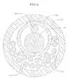
- the mapping assembly 17comprises a generally straight proximal region 38 and a generally circular main region 39.
- the proximal region 38is mounted on the distal shaft 14, as described in more detail below, so that its axis is generally parallel to the axis of the distal shaft.
- the proximal region 38preferably has an exposed length, e.g., not contained within the distal shaft 14, ranging from about 3 mm to about 12 mm, more preferably about 3 mm to about 8 mm, still more preferably about 5 mm inch, but can vary as desired.
- the generally circular main region 39is generally traverse to the catheter body 12.
- the generally circular main region 39is preferably generally perpendicular to the catheter body 12.
- the generally circular main region 39can form a flat circle or can be very slightly helical, as shown in FIG. 3.
- the main region 39has an outer diameter preferably ranging to about 10 mm to about 25 mm, more preferably about 12 mm to about 20 mm.
- the generally circular main region 39can curve in a clockwise direction or a counterclockwise direction.
- the mapping assembly 17is formed of a non-conductive cover 22, which is preferably generally tubular, but can have any cross-sectional shape as desired.
- the non-conductive cover 22can be made of any suitable material, and is preferably made of a biocompatible plastic such as polyurethane or PEBAX.
- the non-conductive cover 22can be pre-formed into the desired generally circular shape of the generally circular main region. Alternatively, the shape of the generally circular main region can be defined by a wire or other component extending through the non-conductive cover 22.
- a pre-formed support member 24extends through the non-conductive cover 22 to define the shape of the generally circular main region 39.
- the support member 24is made of a material having shape-memory, i.e., that can be straightened or bent out of its original shape upon exertion of a force and is capable of substantially returning to its original shape upon removal of the force.
- a particularly preferred material for the support member 24is a nickel/titanium alloy. Such alloys typically comprise about 55% nickel and 45% titanium, but may comprise from about 54% to about 57% nickel with the balance being titanium.
- a preferred nickel/titanium alloyis Nitinol, which has excellent shape memory, together with ductility, strength, corrosion resistance, electrical resistivity and temperature stability.
- a series of ring electrodes 26are mounted on the non-conductive cover 22 of the generally circular main region 39 of the mapping assembly 17, as shown in FIGs. 4a and 4b.
- the ring electrodes 26can be made of any suitable solid conductive material, such as platinum or gold, preferably a combination of platinum and iridium, and mounted onto the non-conductive cover 22 with glue or the like.
- the ring electrodes 26can be formed by coating the non-conductive cover 22 with an electrically conducting material, like platinum, gold and/or iridium. The coating can be applied using sputtering, ion beam deposition or an equivalent technique.
- each ring electrode 26is mounted by first forming a hole in the non-conductive cover 22. An electrode lead wire 50 is fed through the hole. and the ring electrode 26 is welded in place over the lead wire and non-conductive cover 22. The lead wires 50 extend through the non-conductive cover 22 and into the catheter body 12. The proximal end of each lead wire 50 is electrically connected to a suitable connector (not shown), which is connected an appropriate monitor or other device for receiving and displaying the information received from the ring electrodes 26.
- the number of ring electrodes 26 on the assemblycan vary as desired. Preferably the number of ring electrodes ranges from about six to about twenty, more preferably from about eight to about twelve. In one embodiment, the assembly carries ten ring electrodes.
- the ring electrodes 26can be approximately evenly spaced around the generally circular main region 39, as shown in FIG. 4a. In a particularly preferred embodiment, a distance of approximately 5 mm is provided between the centers of the ring electrodes 26.
- the mapping assembly 17includes a series of ring electrode pairs 25.
- Each ring electrode pair 25comprises two closely-spaced ring electrodes 26.
- the term "ring electrode pair”refers to a pair of ring electrodes that are arranged closer to each ether than they are to the other adjacent ring electrodes.
- the distance between two electrodes 26 of an electrode pair 25is less than about 3 mm, more preferably less than about 2 mm, still more preferably from about 0.5 mm to about 1.5 mm.
- the number of electrode pairs 25can vary as desired, and preferably ranges from 6 to 14 pairs, more preferably 10 pairs.
- the mapping assemblycarries 10 pairs of electrodes with a space of approximately 1 mm between the two electrodes 26 of each pair 25.
- each ring electrode 26is relatively short, having a length ranging from about 0.4 mm to about 0.75 mm, with the most distal ring electrode 26c being longer than the other ring electrodes, preferably having a length ranging from about 1 mm to about 1.5 mm.
- the longer ring electrodeprovides a signal to the user when the catheter is being viewed under fluoroscopy.
- the mapping assemblyis generally circular, it can be difficult for the user to determine which electrodes are placed at a particular location in the heart.
- the userhas a reference point when viewing the catheter under fluoroscopy.
- the electrode pairs 25arc preferably approximately evenly spaced around the generally circular main region 39.
- the closely-spaced electrode pairs 25allow for more accurate detection of near field pulmonary vein potential versus far field atrial signals, which is very important when trying to treat atrial fibrillation.
- the near field pulmonary vein potentialsare very small signals whereas the atria, located very close to the pulmonary vein, provides much larger signals. Accordingly, even when the mapping array is placed in the pulmonary vein, it can be difficult for the physician to determine whether the signal is a small, close potential (from the pulmonary vein) or a larger, farther potential (from the atria).
- Closely-spaced bipolespermit the physician to more accurately determine whether he is looking at a close signal or a far signal. Accordingly, by having closely-spaced electrodes, one is able to target exactly the locations of myocardial tissue that have pulmonary vein potentials and therefore allows the clinician to deliver therapy to the specific tissue. Moreover, the closely-spaced electrodes allow the physician to determine the exact anatomical location of the ostium by the electrical signal.
- additional electrodescould be mounted along the distal shaft 14 and/or the generally straight proximal section 39.
- a contraction wire 40is provided to contract the generally circular main region 39 to thereby reduce its diameter.
- the contraction Wire 40has a proximal end anchored in the control handle 16, which is used to manipulate the contraction wire as described further below.
- the contraction wire 40extends through the central lumen 18 of the proximal shaft 13, through the contraction wire lumen 32 of the distal shaft 14 and into the non-conductive cover 22.
- the portion of the contraction wire 40 extending through the non-conductive cover 22is positioned on the side of the generally circular main region 39 closer to the center of the generally circular main region, as best shown in FIGs. 5 and 6.
- the center of the generally circular main regionrefers to the center of the circle formed by the generally circular main region.
- the contraction wire 40extends through a plastic tube 42.
- the plastic tube 42comprise three layers, including an inner layer of polyimide over which a braided layer is formed, the braided layer comprising a braided stainless steel mesh or the like. as is generally known in the art.
- the braided layerenhances the strength of the plastic tube 42, reducing the tendency for contraction wire 40 to straighten the preformed curve of the mapping assembly.
- a thin plastic layer of potytetrafluoroethyleneis provided over the braided layer to protect the braided layer from getting tangled with the lead wires 50 within the non-conductive cover 22.
- the plastic tube 42has a proximal end anchored to the distal end of the distal shaft 14.
- the support member 24extends through the plastic tube 42 with the contraction wire 40.
- the distal ends of the support member 24 and the contraction wire 40are soldered or otherwise attached to a small stainless steel tube 44.
- the relative positions of the contraction wire 40 and the support member 24can be controlled so that the contraction wire 40 can be positioned on the side of the generally circular region closer to the center of the generally circular region, as described above.
- the contraction wire 40 on the inside of the curvepulls the support member 24 to the inside Of the curve, enhancing contraction of the generally circular region 39.
- the plastic tube 42includes a braided layer, it keeps the contraction wire 40 from tearing through the non-conductive cover 22.
- a first compression coil 46is situated within the proximal shaft 13 and distal shaft 14 in surrounding relation to the contraction wire 40.
- the first compression coil 46extends from the proximal end of the proximal shaft 13 and through the contraction wire lumen 32.
- the first compression coil 46is made of any suitable metal, preferably stainless steel, and is tightly wound on itself to provide flexibility, i.e., bending, but to resist compression.
- the inner diameter of the first compression coil 46is preferably slightly larger than the diameter of the contraction wire 40.
- the outer surface of the first compression coil 46is covered by a flexible, non-conductive sheath 68. e.g., made of polyimide tubing.
- the first compression coil 46preferably is formed of a wire having a square or rectangular cross-sectional area, which makes it less compressible than a compression coil formed from a wire having a circular cross-sectional area. As a result, the first compression coil 46 keeps the catheter body 12, and particularly the distal shaft 14, from deflecting when the contraction wire 40 is manipulated to contract the mapping assembly 17 as it absorbs more of the compression.
- the first compression coil 46is anchored at its proximal end to the outer wall 20 of the catheter body 12 by proximal glue joint 70 and to the distal shaft 14 by distal glue joint 72.
- Both glue joints 70 and 72preferably comprise polyurethane glue or the like.
- the gluemay be applied by means of a syringe or the like through a hole made between the outer surface of the catheter body 12 and the central lumen 18. Such a hole may be formed, for example, by a needle or the like that punctures the outer wall 20 of the catheter body 12 which is heated sufficiently to form a permanent hole.
- the glueis then introduced through the hole to the outer surface of the first compression coil 46 and wicks around the outer circumference to form a glue joint about the entire circumference of the compression coil.
- the distal end of the mapping assembly 17is seated closed with a dome 54 of polyurethane glue or the like.
- a short ring 56made of metal or plastic, and preferably polyamide, is mounted within the distal end of the non-conductive cover 22. The short ring 56 prevents the distal end of the non-conductive cover 22 from collapsing, there by maintaining the diameter of the non-conductive cover at its distal end.
- the non-conductive cover 22is attached to the distal shaft by glue or the like.
- the plastic tube 42has its proximal end inserted and glued in the distal end of the distal shaft 14.
- the glue from the plastic tube 42can further serve to anchor the distal end of the first compression coil 46 in place within the contraction wire lumen 32.
- the support member 24extends from the support member lumen 32 into the plastic tube 42 within the non-conductive cover 22.
- the proximal end of the support member 24terminates a short distance within the support member lumen 34, approximately about 5 mm, so as not to adversely affect the ability of the distal shaft 14 to deflect. However, if desired, the proximal end of the support member 24 can extend further into the catheter body 12.
- the lead wires 50 attached to the ring electrodes 26extend through the lead wire lumen 30 of the distal shaft 14, through the central lumen 18 of the catheter body 12, and the control handle 16, and terminate at their proximal end in a connector (not shown).
- the portion of the lead wires 50 extending through the central lumen 18 of the catheter body 12, control handle 16 and proximal end of the distal shaft 14are enclosed within a protective sheath 52, which can be made of any suitable material, preferably polyimide.
- the protective sheath 52is anchored at its distal end to the proximal end of the distal shaft 14 by gluing it in the lead wire lumen 30 with polyurethane glue or the like.
- a deflection wire 64is provided for deflection of the distal shalt 14.
- the deflection wire 64extends through the proximal shaft 13, and is anchored at its proximal end to control handle 16 and at its distal end to the distal shall 14.
- the deflection wire 64is made of any suitable metal, such as stainless steel or Nitinol, and is preferably coated with Teflon® or the like. The coating imparts lubricity to the puller wire 64.
- the puller wire 64preferably has a diameter ranging from about 0.006 to about 0.010 inch.
- the deflection wire 64extends into the defection wire lumen 36 of the distal shaft 14.
- the deflection wire 64is anchored at its distal end to the sidewall of the distal shaft 14. as is generally described in U.S. Patent No. 6,371,955, the disclosure of which is incorporated herein by reference.
- a second compression coil 66is situated within the proximal shaft 13 in surrounding relation to the deflection wire 64.
- the second compression coil 66extends from the proximal end of the proximal shaft 13 to the distal end of the proximal shaft.
- the second compression coil 66is made of any suitable metal, preferably stainless steel, and is tightly wound on itself to provide flexibility, i.e., bending, but to resist compression.
- the inner diameter of the second compression coil 66is preferably slightly larger than the diameter of the deflection wire 64.
- the Teflon® coating on the deflection wire 64allows it to slide freely within the second compression coil 66.
- the outer surface of the second compression coil 66is also covered by a flexible, non-conductive sheath 68, e.g., made of polyimide tubing.
- the second compression coil 66is anchored at its proximal end to the outer wall 20 of the catheter body 12 by the proximal glue joint 70 and to the distal shaft 14 by the distal glue joint 72.
- the deflection wire 64 and second compression coil 66extends through a plastic, preferably Teflon®, puller wire sheath 71, which prevents the puller wire 64 from cutting into the wall of the distai shaft when the distal shaft is deflected.
- the catheterincludes a control handle 16 as shown in FIGs. 8 to 10.
- the control handle 16includes a handle body 74 in which a core 76 is fixedly mounted.
- the core 76is separate from the handle body 74, the core could instead be formed as a single unitary piece with the handle body.
- the corehas a generally cylindrical distal region 75 and a generally cylindrical proximal region 77 having a larger diameter than the proximal region.
- a piston 82is slidahly mounted over the distal region 77 of the core 76. the proximal end of the piston 82 is maintained within the handle body 74, and the distal end of the piston extends outside the handle body.
- a thumb knob 84is mounted in surrounding relation to a portion of the distal end of the piston 82 so that the user can more easily move the piston longitudinally relative to the core 76 and handle body 74.
- the proximal end of the catheter body 12is fixedly mounted to the distal end of the piston 82 through a tip portion 78 that is mounted on the distal old of the piston.
- the proximal end of the catheter body 12is inserted into an axial passage 80 in the tip portion and optionally glued in place.
- the pistonincludes an axial passage 86 in communication with the axial passage 80 of the tip portion 78, and the core 76 includes an axial passage 88 in communication with the axial passage in the piston.
- the lead wires 50can extend out the proximal end of the control handle 16 or can be connected to a connector (not shown) that is incorporated into the control handle as is generally known in the art.
- the proximal end of the deflection wire 64is anchored to the core 76.
- the portion of the axial passage 88 extending through the proximal region 77 of the core 76has a larger diameter than the portion of the axial passage extending through the distal region 75 of the core 76.
- a deflection wire adjuster 90is adjustably mounted, as described further below, in a portion of the axial passage 88 near the distal end of the proximal region 77 of the core 76.
- the deflection wire adjuster 90has an opening 92 extending therethrough in a direction generally transverse, and preferably generally perpendicular, to the axial passage 88 of the core 76.
- the deflection wire 64extends through the opening 92 in the deflection wire adjuster 90 such that the deflection wire changes directions.
- the distal region 77 of the core 76includes a generally rectangular opening 94 that extends generally parallel to the axial passage 88 of the core.
- a channel 96connects the proximal end of the generally rectangular opening 94 to the distal end of tire portion of the axial passage 88 in the proximal region 75 of the core 76.
- the proximal end of the deflection wire 64extends through the channel 96 and into the generally rectangular opening 94.
- a deflection wire anchor 98which can comprise a short piece of hypodermic stock, is fixedly attached, for example, by crimping, to a portion of the proximal end of the deflection wire 64 within the generally rectangular opening 94.
- the deflection wire anchor 98has a diameter greater than the width of the channel 96 and thus prevents the proximal end of the deflection wire 64 from being pulled through the channel, thereby anchoring the deflection wire to the core 76.
- the deflection wire anchor 98is fixedly mounted to the core 76 even though the deflection wire anchor still has a small amount of free play within the opening 94.
- the piston 82is moved distally relative to the handle body 74 and core 76, thereby pulling the catheter body 12 distally relative to the deflection wire 64, which is anchored to the core.
- the deflection wire 64pulls on the side of the distal shaft 14 to which it is anchored. thereby deflecting the distal shalt in that direction.
- the piston 82is moved proximally back to its original position relative to the handle body 74 and core 76.
- Manipulation of the deflection wire adjuster 90adjusts the amount of free play in the deflection wire 64.
- the deflection wire adjuster 90is adjustably mounted in a portion of the axial passage 88 near the distal end of the proximal region 77 of the core 76.
- the portion of the axial passage 88 in which the deflection wire adjuster 90 is mountedincludes a series of ridges 100 extending along the surface of the core 76, with the ridges being generally perpendicular to the axis of the core.
- the deflection wire adjuster 90carries an outwardly extending tab 102 that fits in the spaces between the ridges 100.
- the deflection wire adjuster 90can be moved along the length of the core 76 and snapped into place by placing the tab 102 between two ridges 100. As the deflection wire adjuster 90 is moved proximally (away from catheter body 12) less free play is provided for the deflection wire 64.
- the precise mechanism for adjusting the amount of free play of the deflection wire 64is not critical, and alternative mechanisms can be provided. Alternatively, the deflection wire 64 can be anchored directly to the core 76 so that it is not adjustable.
- the control handle 16is also used for longitudinal movement of the contraction wire 40.
- the contraction wire 40extends from the catheter body 12, through the axial passage 86 in the piston 82 and through the axial passage 88 within the distal region 75 of the core 76.
- the proximal end of the contraction wire 40is anchored to a contraction wire adjuster 104 that is slidably mounted in the core 76.
- the contraction wire adjuster 104is generally rectangular having a bottom region 108 that extends downward through a slot 110 in the proximal region 77 of the core 76, the slot being in communication with the axial passage 88 of the core.
- the proximal end of the contraction wire 40which, as noted above, extends through the axial passage 88, is anchored in the contraction wire adjuster 104 in a manner very similar to the manner in which the deflection wire 64 is anchored to the core 76, as described above.
- a contraction wire anchor 108which can comprise a short piece of hypodermic stock, is fixedly attached, for example, by crimping, to a portion of the proximal end of the contraction wire 40 within an opening 110 in the contraction Wire adjuster 104.
- a channel 112connects the opening 110 to the axial passage 88 in the core.
- the contraction wire anchor 98has a diameter greater than the width of the channel 112 and thus prevents the proximal end of the contraction wire 40 from being pulled through the channel, thereby anchoring the contraction wire to the contraction wire adjuster 104.
- the distal end of the contraction wire adjuster 104is adjustably attached to a cam receiver 106.
- the cam receiver 106is generally tubular, having a short slot 114 extending from its proximal end sized to receive the distal end of the contraction wire adjuster 104.
- the cam receiver 106is slidably mounted over the piston 82 and the distal region 75 of the core 76 with the bottom portion of the contraction wire adjuster 104 positioned in the slot 114 in the core and a corresponding slot 115 in the piston.
- the contraction wire anchor 98is fixedly mounted to the cam receiver 106 through the contraction wire adjuster 104, even though the contraction wire anchor has some free play within the opening 110 in the contraction wire adjuster.
- the top of the distal end of the contraction wire adjuster 104includes a series of outwardly extending teeth 116 that mate with a plurality of notches 118 within the slot 114 of the cam receiver 106 so that the contraction wire adjuster can be snapped into the cam receiver.
- the position of the contraction wire adjuster 104 relative to the cam receiver 106can be longitudinally adjusted by repositioning the teeth 116 relative to the notches 118, to thereby adjust the tension on the contraction wire 40.
- the contraction wire 40is not adjustable, in which case the contraction wire anchor 98 is mounted within an opening (not shown) within the cam receiver 106.
- the cam 120includes a ramped proximal surface 122.
- the cam receiver 106includes a ramped distal surface 123 and an outwardly extending tab 124 at the most distal point of the ramped distal surface.
- the tab 124contacts the ramped proximal surface 122 of the cam 120.
- the ramped proximal surface 112correspondingly rotates and pushes the cam receiver 104 proximally relative to the core 76 and catheter body 12.
- the contraction wire 40is pulled proximally to thereby contract the generally circular main region 39 of the mapping assembly 17.
- the ramped proximal surface 122 of the cam 120includes an outwardly extending tab 126 at its most proximal point.
- the tab 124 on the cam receiver 104contacts the tab 126 on the ramped proximal surface 122, thereby prohibiting further rotation of the cam relative to the cam receiver.
- the tab 126 on the ramped proximal surface 122pushes the tab 124 on the cam receiver 104 such that the cam receiver moves distally, thereby releasing the tension on the contraction wire 40 so that the generally circular main region 39 of the mapping assembly 17 returns to its original configuration.
- the direction of the ramped proximal surface 122can be changed so that clockwise rotation of the cam 120 causes contraction of generally circular main region 39 of the mapping assembly 17 and counterclockwise rotation causes it to return to its original configuration.
- a flexible grip 128is provided over the cam 120 for the user to more easily and comfortably rotate the cam 120.
- a suitable guiding sheathis inserted into the patient with its distal end positioned at a desired mapping location.
- An example of a suitable guiding sheath for use in connection with the present inventionis the PrefaceTM Braiding Guiding Sheath, commercially available from Biosense Webster, Inc. (Diamond Bar, California).
- the distal end of the sheathis guided into one of the atria.
- a catheter in accordance with the present inventionis fed through the guiding sheath until its distal end extends out of the distal end of the guiding sheath.
- the mapping assembly 17is straightened to fit through the sheath.
- mapping assembly 17is then inserted into a pulmonary vein or other tubular region (such as the coronary sinus, superior vena cava, or inferior vena cava) so that the outer circumference of the generally circular main region 39 of the assembly is in contact with a circumference inside the tubular region.
- a pulmonary vein or other tubular regionsuch as the coronary sinus, superior vena cava, or inferior vena cava
- the outer circumference of the generally circular main region 39 of the assemblyis in contact with a circumference inside the tubular region.
- at least about 50%, more preferably at least about 70%, and still more preferably at least about 80% of the circumference of the generally circular main regionis in contact with a circumference inside the tubular region.
- the circular arrangement of the electrodes 26permits measurement of the electrical activity at that circumference of the tubular structure so that ectopic beats between the electrodes can be identified.
- the size of the generally circular main region 39permits measurement of electrical activity along a diameter of a pulmonary vein or other tubular structure of or near the heart because the circular main region has a diameter generally corresponding to that of a pulmonary vein or the coronary sinus.
Landscapes
- Health & Medical Sciences (AREA)
- Life Sciences & Earth Sciences (AREA)
- Biophysics (AREA)
- Pulmonology (AREA)
- Engineering & Computer Science (AREA)
- Anesthesiology (AREA)
- Biomedical Technology (AREA)
- Heart & Thoracic Surgery (AREA)
- Hematology (AREA)
- Animal Behavior & Ethology (AREA)
- General Health & Medical Sciences (AREA)
- Public Health (AREA)
- Veterinary Medicine (AREA)
- Media Introduction/Drainage Providing Device (AREA)
Abstract
Description
The distal end of the
Claims (11)
- A multifunctional handle comprising:a handle body;a core mounted within the handle body, the core having a longitudinal passageextending therethrough;a piston having a distal end mounted in the handle body and a proximal endextending outside the handle body, the piston being longitudinally moveable relative to thecore and handle body;a first puller wire anchor fixedly mounted to the core;a cam receiver mounted within the handle body so that the cam receiver islongitudinally slidable relative to the piston and core;a second puller wire anchor fixedly mounted to the cam receiver; anda generally cylindrical cam mounted distal to the cam receiver in surroundingrelation to the piston, wherein rotation of the cam relative to the piston causes longitudinalmovement of the cam receiver and second puller wire anchor.
- A multifunctional handle according to claim 1, wherein the cam has aramped proximal end.
- A multifunctional handle according to claim 2, wherein the cam receiver isgenerally tubular and is mounted in surrounding relation to the core.
- A multifunctional handle according to claim 3, wherein the cam receiverhas a distal end with a tab extending distally therefrom, wherein the tab contacts theramped proximal end of the cam.
- A multifunctional handle according to claim 4, wherein the rampedproximal end of the cam has a tab extending proximally therefrom, such that, when thecam is rotated relative to the piston and core, the tab on the cam contacts the tab on thecore to thereby limit the ability of the cam to rotate.
- A multifunctional handle according to claim 1, wherein the second pullerwire anchor is fixedly mounted to the cam receiver by being fixedly mounted within apuller wire adjuster that is adjustably mounted to the cam receiver such that thelongitudinal position of the puller wire adjuster relative to the cam can be altered.
- A multifunctional handle according to claim 6, wherein the puller wireadjuster has one or more teeth extending outward therefrom in a direction generallyperpendicular to the axis of the handle and is mounted within a slot in the cam receiver, theslot containing one or more notches that mate with the teeth.
- A multifunctional handle according to claim 1, further comprising a pullerwire adjuster mounted within the core at a position proximal to the first puller wire anchor,wherein the longitudinal position of the puller wire adjuster relative to the core can bealtered, the puller wire adjuster comprising an opening extending therethrough in adirection generally transverse to the axis of the handle, such that a wire extending throughthe core and having an end anchored to the first puller wire anchor can pass through theopening of the puller wire adjuster and reverse directions.
- A multifunctional handle comprising:a handle body;a core mounted within the handle body, the core having a longitudinal passageextending therethrough;a piston having a distal end mounted in the handle body in surrounding relation tothe core and a proximal end extending outside the handle body, the piston beinglongitudinally moveable relative to the core and handle body;a first puller wire anchor fixedly mounted to the core;a generally tubular cam receiver having proximal and distal ends and beingmounted in surrounding relation to the piston so that the cam receiver is longitudinallyslidable over the piston;a second puller wire anchor fixedly mounted to the cam receiver; anda generally cylindrical cam mounted distal to the cam receiver in surroundingrelation to the piston and core and having a ramped proximal end, wherein rotation of the cam relative to the piston and core causes longitudinal movement of the cam receiver andsecond puller wire anchor.
- A multifunctional handle according to claim 9, wherein the cam receiverhas a tab extending distally therefrom that contacts the ramped proximal end of the cam.
- A catheter comprising:wherein the first puller wire is fixedly mounted to the core such that longitudinalmovement of the piston and catheter body relative to the core causes longitudinalmovement of the first puller wire relative to the catheter body,an elongated catheter body having proximal and distal ends;a first puller wire extending through the catheter body and having proximal anddistal ends, wherein the distal end of the first puller wire is anchored at or near the distalend of the catheter body or to a structure mounted at the distal end of the catheter body;a second puller wire extending through the catheter body and having proximal anddistal ends, wherein the distal end of the second puller wire is anchored at or near the distalend of the catheter body or to a structure mounted at the distal end of the catheter body;a control handle at the proximal end of the catheter body, the control handlecomprising:a handle body;a core mounted within the handle body, the core having a longitudinalpassage extending therethrough;a piston having a distal end mounted in the handle body and a proximal endextending outside the handle body, wherein the proximal end of the catheter is mounted tothe piston, the piston being longitudinally moveable relative to the core and handle body;a cam receiver mounted within the handle body so that the cam receiver islongitudinally slidable relative to the piston and core; anda generally cylindrical cam mounted distal to the cam receiver insurrounding relation to the piston, wherein rotation of the cam relative to the piston causeslongitudinal movement of the cam receiver and second puller wire anchor;
and wherein the second puller wire is anchored to the cam receiver such thatrotation of the cam causes longitudinal movement of the cam receiver and second pullerwire relative to the piston and catheter body.
Applications Claiming Priority (2)
| Application Number | Priority Date | Filing Date | Title |
|---|---|---|---|
| US10/386,594US6987995B2 (en) | 2003-03-12 | 2003-03-12 | Multifunctional catheter handle |
| US386594 | 2003-03-12 |
Publications (3)
| Publication Number | Publication Date |
|---|---|
| EP1457226A2true EP1457226A2 (en) | 2004-09-15 |
| EP1457226A3 EP1457226A3 (en) | 2005-04-27 |
| EP1457226B1 EP1457226B1 (en) | 2007-04-25 |
Family
ID=32771593
Family Applications (1)
| Application Number | Title | Priority Date | Filing Date |
|---|---|---|---|
| EP04251416AExpired - LifetimeEP1457226B1 (en) | 2003-03-12 | 2004-03-11 | Multifunctional catheter handle |
Country Status (4)
| Country | Link |
|---|---|
| US (3) | US6987995B2 (en) |
| EP (1) | EP1457226B1 (en) |
| JP (1) | JP4401827B2 (en) |
| DE (1) | DE602004006039T2 (en) |
Cited By (6)
| Publication number | Priority date | Publication date | Assignee | Title |
|---|---|---|---|---|
| EP2471455A3 (en)* | 2010-12-30 | 2012-10-17 | Biosense Webster, Inc. | Catheter with single axial sensors |
| US8617087B2 (en) | 2010-12-03 | 2013-12-31 | Biosense Webster, Inc. | Control handle with rotational cam mechanism for contraction/deflection of medical device |
| EP2792382A1 (en)* | 2005-12-19 | 2014-10-22 | Cook Medical Technologies LLC | Medical catheters of modular construction |
| CN108778388A (en)* | 2016-03-21 | 2018-11-09 | 爱德华兹生命科学公司 | Cam-controlled multi-directional steerable handle |
| US10849521B2 (en) | 2015-12-23 | 2020-12-01 | Biosense Webster (Israel) Ltd. | Multi-layered catheter shaft construction with embedded single axial sensors, and related methods |
| US12396657B2 (en) | 2021-04-29 | 2025-08-26 | Biosense Webster (Israel) Ltd. | Non-linear single axis navigation sensor with strain relief |
Families Citing this family (115)
| Publication number | Priority date | Publication date | Assignee | Title |
|---|---|---|---|---|
| US20050267495A1 (en)* | 2004-05-17 | 2005-12-01 | Gateway Medical, Inc. | Systems and methods for closing internal tissue defects |
| US6733499B2 (en)* | 2002-02-28 | 2004-05-11 | Biosense Webster, Inc. | Catheter having circular ablation assembly |
| US6752767B2 (en) | 2002-04-16 | 2004-06-22 | Vivant Medical, Inc. | Localization element with energized tip |
| US7998062B2 (en) | 2004-03-29 | 2011-08-16 | Superdimension, Ltd. | Endoscope structures and techniques for navigating to a target in branched structure |
| US6987995B2 (en)* | 2003-03-12 | 2006-01-17 | Biosense Webster, Inc. | Multifunctional catheter handle |
| EP2113189B1 (en) | 2003-09-15 | 2013-09-04 | Covidien LP | System of accessories for use with bronchoscopes |
| EP2316328B1 (en) | 2003-09-15 | 2012-05-09 | Super Dimension Ltd. | Wrap-around holding device for use with bronchoscopes |
| US7967829B2 (en)* | 2003-10-09 | 2011-06-28 | Boston Scientific Scimed, Inc. | Medical device delivery system |
| US20070149246A1 (en)* | 2004-01-09 | 2007-06-28 | Revolabs, Inc. | Wireless multi-user audio system |
| US8764725B2 (en) | 2004-02-09 | 2014-07-01 | Covidien Lp | Directional anchoring mechanism, method and applications thereof |
| US20060089637A1 (en)* | 2004-10-14 | 2006-04-27 | Werneth Randell L | Ablation catheter |
| US8617152B2 (en)* | 2004-11-15 | 2013-12-31 | Medtronic Ablation Frontiers Llc | Ablation system with feedback |
| US7429261B2 (en)* | 2004-11-24 | 2008-09-30 | Ablation Frontiers, Inc. | Atrial ablation catheter and method of use |
| US7468062B2 (en) | 2004-11-24 | 2008-12-23 | Ablation Frontiers, Inc. | Atrial ablation catheter adapted for treatment of septal wall arrhythmogenic foci and method of use |
| EP2759276A1 (en) | 2005-06-20 | 2014-07-30 | Medtronic Ablation Frontiers LLC | Ablation catheter |
| AU2006268238A1 (en)* | 2005-07-11 | 2007-01-18 | Medtronic Ablation Frontiers Llc | Low power tissue ablation system |
| US8657814B2 (en) | 2005-08-22 | 2014-02-25 | Medtronic Ablation Frontiers Llc | User interface for tissue ablation system |
| WO2007059199A2 (en) | 2005-11-14 | 2007-05-24 | C.R. Bard, Inc. | Sling anchor system |
| JP2009528851A (en)* | 2005-12-28 | 2009-08-13 | シー・アール・バード・インコーポレイテツド | Apparatus and method for inserting an implant |
| USD550356S1 (en)* | 2006-08-04 | 2007-09-04 | Cathrx Ltd | Catheter handle |
| WO2008033950A2 (en) | 2006-09-13 | 2008-03-20 | C. R. Bard, Inc. | Urethral support system |
| US8641704B2 (en)* | 2007-05-11 | 2014-02-04 | Medtronic Ablation Frontiers Llc | Ablation therapy system and method for treating continuous atrial fibrillation |
| US8905920B2 (en) | 2007-09-27 | 2014-12-09 | Covidien Lp | Bronchoscope adapter and method |
| US8206280B2 (en) | 2007-11-13 | 2012-06-26 | C. R. Bard, Inc. | Adjustable tissue support member |
| US8292880B2 (en) | 2007-11-27 | 2012-10-23 | Vivant Medical, Inc. | Targeted cooling of deployable microwave antenna |
| US8103327B2 (en)* | 2007-12-28 | 2012-01-24 | Rhythmia Medical, Inc. | Cardiac mapping catheter |
| WO2009122273A2 (en) | 2008-04-03 | 2009-10-08 | Superdimension, Ltd. | Magnetic interference detection system and method |
| EP2297673B1 (en) | 2008-06-03 | 2020-04-22 | Covidien LP | Feature-based registration method |
| US8218847B2 (en) | 2008-06-06 | 2012-07-10 | Superdimension, Ltd. | Hybrid registration method |
| US8323209B2 (en)* | 2008-06-06 | 2012-12-04 | Williams Iii John | Chorionic villus sampling catheter |
| US8932207B2 (en) | 2008-07-10 | 2015-01-13 | Covidien Lp | Integrated multi-functional endoscopic tool |
| US10517719B2 (en) | 2008-12-22 | 2019-12-31 | Valtech Cardio, Ltd. | Implantation of repair devices in the heart |
| US8712550B2 (en) | 2008-12-30 | 2014-04-29 | Biosense Webster, Inc. | Catheter with multiple electrode assemblies for use at or near tubular regions of the heart |
| US8808345B2 (en)* | 2008-12-31 | 2014-08-19 | Medtronic Ardian Luxembourg S.A.R.L. | Handle assemblies for intravascular treatment devices and associated systems and methods |
| US8611984B2 (en) | 2009-04-08 | 2013-12-17 | Covidien Lp | Locatable catheter |
| US8747351B2 (en) | 2009-08-28 | 2014-06-10 | Biosense Webster, Inc. | Catheter with multi-functional control handle having linear mechanism |
| US9033916B2 (en)* | 2009-08-28 | 2015-05-19 | Biosense Webster, Inc. | Catheter with multi-functional control handle having rotational mechanism |
| US8449599B2 (en) | 2009-12-04 | 2013-05-28 | Edwards Lifesciences Corporation | Prosthetic valve for replacing mitral valve |
| US10582834B2 (en) | 2010-06-15 | 2020-03-10 | Covidien Lp | Locatable expandable working channel and method |
| US10314650B2 (en) | 2010-06-16 | 2019-06-11 | Biosense Webster (Israel) Ltd. | Spectral sensing of ablation |
| US11490957B2 (en) | 2010-06-16 | 2022-11-08 | Biosense Webster (Israel) Ltd. | Spectral sensing of ablation |
| USD638934S1 (en)* | 2010-10-22 | 2011-05-31 | Greatbatch Ltd. | Catheter handle |
| US20120158021A1 (en)* | 2010-12-19 | 2012-06-21 | Mitralign, Inc. | Steerable guide catheter having preformed curved shape |
| EP3345573B1 (en) | 2011-06-23 | 2020-01-29 | Valtech Cardio, Ltd. | Closure element for use with annuloplasty structure |
| US9220433B2 (en)* | 2011-06-30 | 2015-12-29 | Biosense Webster (Israel), Ltd. | Catheter with variable arcuate distal section |
| US9662169B2 (en) | 2011-07-30 | 2017-05-30 | Biosense Webster (Israel) Ltd. | Catheter with flow balancing valve |
| US9717555B2 (en)* | 2012-05-14 | 2017-08-01 | Biosense Webster (Israel), Ltd. | Catheter with helical end section for vessel ablation |
| US9439763B2 (en) | 2013-02-04 | 2016-09-13 | Edwards Lifesciences Corporation | Prosthetic valve for replacing mitral valve |
| US9622863B2 (en) | 2013-11-22 | 2017-04-18 | Edwards Lifesciences Corporation | Aortic insufficiency repair device and method |
| US10952593B2 (en) | 2014-06-10 | 2021-03-23 | Covidien Lp | Bronchoscope adapter |
| US10206595B2 (en) | 2014-11-17 | 2019-02-19 | 3VO Medical, Inc. | Intrauterine balloon apparatus, system, and method for augmenting uterine birthing forces during parturition |
| US9414857B2 (en)* | 2014-11-20 | 2016-08-16 | Medtronic, Inc. | Delivery system assemblies for implantable medical devices |
| WO2016090308A1 (en) | 2014-12-04 | 2016-06-09 | Edwards Lifesciences Corporation | Percutaneous clip for repairing a heart valve |
| US11534239B2 (en) | 2014-12-22 | 2022-12-27 | Biosense Webster (Israel) Ltd. | Systems and method or uses of ablating cardiac tissue |
| US10426555B2 (en) | 2015-06-03 | 2019-10-01 | Covidien Lp | Medical instrument with sensor for use in a system and method for electromagnetic navigation |
| US10799676B2 (en) | 2016-03-21 | 2020-10-13 | Edwards Lifesciences Corporation | Multi-direction steerable handles for steering catheters |
| US10835714B2 (en) | 2016-03-21 | 2020-11-17 | Edwards Lifesciences Corporation | Multi-direction steerable handles for steering catheters |
| US10799677B2 (en) | 2016-03-21 | 2020-10-13 | Edwards Lifesciences Corporation | Multi-direction steerable handles for steering catheters |
| US11219746B2 (en) | 2016-03-21 | 2022-01-11 | Edwards Lifesciences Corporation | Multi-direction steerable handles for steering catheters |
| US10478254B2 (en) | 2016-05-16 | 2019-11-19 | Covidien Lp | System and method to access lung tissue |
| US10905329B2 (en) | 2016-06-09 | 2021-02-02 | Biosense Webster (Israel) Ltd. | Multi-function conducting elements for a catheter |
| US10973638B2 (en) | 2016-07-07 | 2021-04-13 | Edwards Lifesciences Corporation | Device and method for treating vascular insufficiency |
| US10722311B2 (en) | 2016-10-28 | 2020-07-28 | Covidien Lp | System and method for identifying a location and/or an orientation of an electromagnetic sensor based on a map |
| US10615500B2 (en) | 2016-10-28 | 2020-04-07 | Covidien Lp | System and method for designing electromagnetic navigation antenna assemblies |
| US10792106B2 (en) | 2016-10-28 | 2020-10-06 | Covidien Lp | System for calibrating an electromagnetic navigation system |
| US10751126B2 (en) | 2016-10-28 | 2020-08-25 | Covidien Lp | System and method for generating a map for electromagnetic navigation |
| US10517505B2 (en) | 2016-10-28 | 2019-12-31 | Covidien Lp | Systems, methods, and computer-readable media for optimizing an electromagnetic navigation system |
| US10418705B2 (en) | 2016-10-28 | 2019-09-17 | Covidien Lp | Electromagnetic navigation antenna assembly and electromagnetic navigation system including the same |
| US10638952B2 (en) | 2016-10-28 | 2020-05-05 | Covidien Lp | Methods, systems, and computer-readable media for calibrating an electromagnetic navigation system |
| US10446931B2 (en) | 2016-10-28 | 2019-10-15 | Covidien Lp | Electromagnetic navigation antenna assembly and electromagnetic navigation system including the same |
| US10653862B2 (en) | 2016-11-07 | 2020-05-19 | Edwards Lifesciences Corporation | Apparatus for the introduction and manipulation of multiple telescoping catheters |
| US11400205B2 (en) | 2016-11-23 | 2022-08-02 | Biosense Webster (Israel) Ltd. | Balloon-in-balloon irrigation balloon catheter |
| US10905554B2 (en) | 2017-01-05 | 2021-02-02 | Edwards Lifesciences Corporation | Heart valve coaptation device |
| EP4613214A2 (en) | 2017-04-18 | 2025-09-10 | Edwards Lifesciences Corporation | Heart valve sealing devices and delivery devices therefor |
| US11224511B2 (en) | 2017-04-18 | 2022-01-18 | Edwards Lifesciences Corporation | Heart valve sealing devices and delivery devices therefor |
| US10799312B2 (en) | 2017-04-28 | 2020-10-13 | Edwards Lifesciences Corporation | Medical device stabilizing apparatus and method of use |
| US10959846B2 (en) | 2017-05-10 | 2021-03-30 | Edwards Lifesciences Corporation | Mitral valve spacer device |
| US12029545B2 (en) | 2017-05-30 | 2024-07-09 | Biosense Webster (Israel) Ltd. | Catheter splines as location sensors |
| US11051940B2 (en) | 2017-09-07 | 2021-07-06 | Edwards Lifesciences Corporation | Prosthetic spacer device for heart valve |
| US11065117B2 (en) | 2017-09-08 | 2021-07-20 | Edwards Lifesciences Corporation | Axisymmetric adjustable device for treating mitral regurgitation |
| US11040174B2 (en)* | 2017-09-19 | 2021-06-22 | Edwards Lifesciences Corporation | Multi-direction steerable handles for steering catheters |
| US11219489B2 (en) | 2017-10-31 | 2022-01-11 | Covidien Lp | Devices and systems for providing sensors in parallel with medical tools |
| FI3964175T3 (en) | 2018-01-09 | 2024-12-03 | Edwards Lifesciences Corp | Native valve repair devices |
| US10231837B1 (en) | 2018-01-09 | 2019-03-19 | Edwards Lifesciences Corporation | Native valve repair devices and procedures |
| US10123873B1 (en) | 2018-01-09 | 2018-11-13 | Edwards Lifesciences Corporation | Native valve repair devices and procedures |
| US10111751B1 (en) | 2018-01-09 | 2018-10-30 | Edwards Lifesciences Corporation | Native valve repair devices and procedures |
| US11071585B2 (en) | 2018-09-14 | 2021-07-27 | Biosense Webster (Israel) Ltd. | Systems and methods of ablating cardiac tissue |
| JP2022500160A (en) | 2018-09-14 | 2022-01-04 | バイオセンス・ウエブスター・(イスラエル)・リミテッドBiosense Webster (Israel), Ltd. | Systems and methods or uses for ablating heart tissue |
| WO2020053831A1 (en) | 2018-09-14 | 2020-03-19 | Biosense Webster (Israel) Ltd. | Systems for ablating cardiac tissue |
| US10945844B2 (en) | 2018-10-10 | 2021-03-16 | Edwards Lifesciences Corporation | Heart valve sealing devices and delivery devices therefor |
| CN113226223A (en) | 2018-11-20 | 2021-08-06 | 爱德华兹生命科学公司 | Deployment tools and methods for delivering devices to native heart valves |
| CA3118988A1 (en) | 2018-11-21 | 2020-05-28 | Edwards Lifesciences Corporation | Heart valve sealing devices, delivery devices therefor, and retrieval devices |
| CR20210312A (en) | 2018-11-29 | 2021-09-14 | Edwards Lifesciences Corp | Catheterization method and apparatus |
| ES2969252T3 (en) | 2019-02-14 | 2024-05-17 | Edwards Lifesciences Corp | Heart valve sealing devices and delivery devices therefor |
| US12220541B2 (en) | 2019-07-03 | 2025-02-11 | Biosense Webster (Israel) Ltd. | Sensing and mapping catheter for guiding and supporting balloon catheter |
| US12004878B2 (en) | 2019-07-03 | 2024-06-11 | Biosense Webster (Israel) Ltd. | Composite catheter with single axial sensors and ring electrodes and related methods |
| US12369975B2 (en) | 2019-09-12 | 2025-07-29 | Biosense Webster (Israel) Ltd. | Balloon catheter with force sensor |
| US11633228B2 (en) | 2019-10-04 | 2023-04-25 | Biosense Webster (Israel) Ltd. | Identifying pulmonary vein occlusion by dimension deformations of balloon catheter |
| US12369974B2 (en) | 2019-10-10 | 2025-07-29 | Biosense Webster (Israel) Ltd. | Touch indication of balloon-catheter ablation electrode via balloon surface temperature measurement |
| CN110575604A (en)* | 2019-10-14 | 2019-12-17 | 苏州法兰克曼医疗器械有限公司 | A medical device with an angle adjustment device |
| US12137967B2 (en) | 2019-11-12 | 2024-11-12 | Biosense Webster (Israel) Ltd. | Accurate positioning and shape visualization of balloon catheter ablation tags |
| US20220095947A1 (en) | 2020-09-29 | 2022-03-31 | Biosense Webster (Israel) Ltd. | Circular navigation catheter with surface mounted inductive navigation sensors |
| US12239364B2 (en) | 2020-10-07 | 2025-03-04 | Biosense Webster (Israel) Ltd. | Printed proximal electrodes of an expandable catheter for use as a common electrode |
| US11974803B2 (en) | 2020-10-12 | 2024-05-07 | Biosense Webster (Israel) Ltd. | Basket catheter with balloon |
| US11957852B2 (en) | 2021-01-14 | 2024-04-16 | Biosense Webster (Israel) Ltd. | Intravascular balloon with slidable central irrigation tube |
| CN112704465A (en)* | 2021-01-15 | 2021-04-27 | 宁波胜杰康生物科技有限公司 | Rotatable endoscope outer channel |
| US11849995B2 (en) | 2021-02-18 | 2023-12-26 | Biosense Webster (Israel) Ltd. | Detection of balloon catheter tissue contact using optical measurement |
| IL307916A (en) | 2021-04-26 | 2023-12-01 | Pulse Biosciences Inc | Circumferential ablation devices and methods |
| US20230009573A1 (en) | 2021-07-09 | 2023-01-12 | Biosense Webster (Israel) Ltd. | Ablation and mapping with a singular multi-electrode catheter |
| USD1034977S1 (en)* | 2021-07-23 | 2024-07-09 | Ipg Photonics Corporation | Control handle grip for a catheter |
| US20230043627A1 (en) | 2021-08-06 | 2023-02-09 | Biosense Webster (Israel) Ltd. | Steerable sheath and catheter with circular deflection |
| US20230058649A1 (en) | 2021-08-17 | 2023-02-23 | Biosense Webster (Israel) Ltd. | Sheath, catheter, and method of controlling radial orientation thereof |
| US20230226638A1 (en) | 2022-01-20 | 2023-07-20 | Biosense Webster (Israel) Ltd. | Intravascular device including high voltage coaxial conductor wiring |
| CN114305704B (en)* | 2022-03-11 | 2022-05-27 | 极限人工智能(北京)有限公司 | Multifunctional channel device and minimally invasive surgery robot |
| USD1071198S1 (en) | 2023-06-28 | 2025-04-15 | Edwards Lifesciences Corporation | Cradle |
Family Cites Families (11)
| Publication number | Priority date | Publication date | Assignee | Title |
|---|---|---|---|---|
| US4960134A (en)* | 1988-11-18 | 1990-10-02 | Webster Wilton W Jr | Steerable catheter |
| US5826576A (en)* | 1996-08-08 | 1998-10-27 | Medtronic, Inc. | Electrophysiology catheter with multifunction wire and method for making |
| US6013052A (en)* | 1997-09-04 | 2000-01-11 | Ep Technologies, Inc. | Catheter and piston-type actuation device for use with same |
| US6123699A (en)* | 1997-09-05 | 2000-09-26 | Cordis Webster, Inc. | Omni-directional steerable catheter |
| US6267746B1 (en) | 1999-03-22 | 2001-07-31 | Biosense Webster, Inc. | Multi-directional steerable catheters and control handles |
| US6468260B1 (en)* | 1999-05-07 | 2002-10-22 | Biosense Webster, Inc. | Single gear drive bidirectional control handle for steerable catheter |
| US6371955B1 (en)* | 1999-08-10 | 2002-04-16 | Biosense Webster, Inc. | Atrial branding iron catheter and a method for treating atrial fibrillation |
| US6795721B2 (en)* | 2000-01-27 | 2004-09-21 | Biosense Webster, Inc. | Bidirectional catheter having mapping assembly |
| US6522933B2 (en)* | 2001-03-30 | 2003-02-18 | Biosense, Webster, Inc. | Steerable catheter with a control handle having a pulley mechanism |
| US6913594B2 (en)* | 2001-12-31 | 2005-07-05 | Biosense Webster, Inc. | Dual-function catheter handle |
| US6987995B2 (en)* | 2003-03-12 | 2006-01-17 | Biosense Webster, Inc. | Multifunctional catheter handle |
- 2003
- 2003-03-12USUS10/386,594patent/US6987995B2/ennot_activeExpired - Lifetime
- 2004
- 2004-03-11EPEP04251416Apatent/EP1457226B1/ennot_activeExpired - Lifetime
- 2004-03-11DEDE602004006039Tpatent/DE602004006039T2/ennot_activeExpired - Lifetime
- 2004-03-11JPJP2004069323Apatent/JP4401827B2/ennot_activeExpired - Fee Related
- 2005
- 2005-12-30USUS11/322,582patent/US7274957B2/ennot_activeExpired - Lifetime
- 2007
- 2007-09-25USUS11/861,142patent/US7720517B2/ennot_activeExpired - Lifetime
Cited By (16)
| Publication number | Priority date | Publication date | Assignee | Title |
|---|---|---|---|---|
| EP2792382A1 (en)* | 2005-12-19 | 2014-10-22 | Cook Medical Technologies LLC | Medical catheters of modular construction |
| US10252031B2 (en) | 2010-12-03 | 2019-04-09 | Biosense Webster, Inc. | Control handle with rotational cam mechanism for contraction/deflection of medical device |
| US11213655B2 (en) | 2010-12-03 | 2022-01-04 | Biosense Webster, Inc. | Control handle with rotational cam mechanism for contraction/deflection of medical device |
| US11931527B2 (en) | 2010-12-03 | 2024-03-19 | Biosense Webster (Israel) Ltd. | Control handle with rotational cam mechanism for contraction/deflection of medical device |
| US8617087B2 (en) | 2010-12-03 | 2013-12-31 | Biosense Webster, Inc. | Control handle with rotational cam mechanism for contraction/deflection of medical device |
| US9220868B2 (en) | 2010-12-03 | 2015-12-29 | Biosense Webster, Inc. | Control handle with rotational cam mechanism for contraction/deflection of medical device |
| US9682214B2 (en) | 2010-12-03 | 2017-06-20 | Biosense Webster (Israel) Ltd. | Control handle with rotational cam mechanism for contraction/deflection of medical device |
| EP2471455A3 (en)* | 2010-12-30 | 2012-10-17 | Biosense Webster, Inc. | Catheter with single axial sensors |
| US10405774B2 (en) | 2010-12-30 | 2019-09-10 | Biosense Webster, Inc. | Catheter with single axial sensors |
| RU2503408C2 (en)* | 2010-12-30 | 2014-01-10 | Байосенс Уэбстер, Инк. | Catheter with uniaxial sensors |
| US8792962B2 (en) | 2010-12-30 | 2014-07-29 | Biosense Webster, Inc. | Catheter with single axial sensors |
| US10849521B2 (en) | 2015-12-23 | 2020-12-01 | Biosense Webster (Israel) Ltd. | Multi-layered catheter shaft construction with embedded single axial sensors, and related methods |
| CN108778388A (en)* | 2016-03-21 | 2018-11-09 | 爱德华兹生命科学公司 | Cam-controlled multi-directional steerable handle |
| EP3432967A4 (en)* | 2016-03-21 | 2019-05-22 | Edwards Lifesciences Corporation | MULTIDIRECTIONAL ADJUSTABLE HANDLES WITH CAM CONTROL |
| EP4154935A1 (en)* | 2016-03-21 | 2023-03-29 | Edwards Lifesciences Corporation | Cam controlled multi-direction steerable handles |
| US12396657B2 (en) | 2021-04-29 | 2025-08-26 | Biosense Webster (Israel) Ltd. | Non-linear single axis navigation sensor with strain relief |
Also Published As
| Publication number | Publication date |
|---|---|
| EP1457226A3 (en) | 2005-04-27 |
| DE602004006039T2 (en) | 2007-12-27 |
| JP2004275766A (en) | 2004-10-07 |
| US7720517B2 (en) | 2010-05-18 |
| US20060106297A1 (en) | 2006-05-18 |
| JP4401827B2 (en) | 2010-01-20 |
| US20080009882A1 (en) | 2008-01-10 |
| US20040181135A1 (en) | 2004-09-16 |
| EP1457226B1 (en) | 2007-04-25 |
| DE602004006039D1 (en) | 2007-06-06 |
| US6987995B2 (en) | 2006-01-17 |
| US7274957B2 (en) | 2007-09-25 |
Similar Documents
| Publication | Publication Date | Title |
|---|---|---|
| US6987995B2 (en) | Multifunctional catheter handle | |
| EP1457225B1 (en) | Catheter with contractable mapping assembly | |
| EP1287782B1 (en) | Catheter having mapping assembly | |
| EP1120082B1 (en) | Catheter having mapping assembly | |
| US7917187B2 (en) | Catheter having mapping assembly |
Legal Events
| Date | Code | Title | Description |
|---|---|---|---|
| PUAI | Public reference made under article 153(3) epc to a published international application that has entered the european phase | Free format text:ORIGINAL CODE: 0009012 | |
| AK | Designated contracting states | Kind code of ref document:A2 Designated state(s):AT BE BG CH CY CZ DE DK EE ES FI FR GB GR HU IE IT LI LU MC NL PL PT RO SE SI SK TR | |
| AX | Request for extension of the european patent | Extension state:AL HR LT LV MK | |
| PUAL | Search report despatched | Free format text:ORIGINAL CODE: 0009013 | |
| AK | Designated contracting states | Kind code of ref document:A3 Designated state(s):AT BE BG CH CY CZ DE DK EE ES FI FR GB GR HU IE IT LI LU MC NL PL PT RO SE SI SK TR | |
| AX | Request for extension of the european patent | Extension state:AL HR LT LV MK | |
| 17P | Request for examination filed | Effective date:20051006 | |
| AKX | Designation fees paid | Designated state(s):DE GB NL | |
| GRAP | Despatch of communication of intention to grant a patent | Free format text:ORIGINAL CODE: EPIDOSNIGR1 | |
| GRAS | Grant fee paid | Free format text:ORIGINAL CODE: EPIDOSNIGR3 | |
| GRAA | (expected) grant | Free format text:ORIGINAL CODE: 0009210 | |
| AK | Designated contracting states | Kind code of ref document:B1 Designated state(s):DE GB NL | |
| REG | Reference to a national code | Ref country code:GB Ref legal event code:FG4D | |
| REF | Corresponds to: | Ref document number:602004006039 Country of ref document:DE Date of ref document:20070606 Kind code of ref document:P | |
| PLBE | No opposition filed within time limit | Free format text:ORIGINAL CODE: 0009261 | |
| STAA | Information on the status of an ep patent application or granted ep patent | Free format text:STATUS: NO OPPOSITION FILED WITHIN TIME LIMIT | |
| 26N | No opposition filed | Effective date:20080128 | |
| PGFP | Annual fee paid to national office [announced via postgrant information from national office to epo] | Ref country code:NL Payment date:20220215 Year of fee payment:19 | |
| PGFP | Annual fee paid to national office [announced via postgrant information from national office to epo] | Ref country code:GB Payment date:20230202 Year of fee payment:20 Ref country code:DE Payment date:20230131 Year of fee payment:20 | |
| REG | Reference to a national code | Ref country code:NL Ref legal event code:MM Effective date:20230401 | |
| PG25 | Lapsed in a contracting state [announced via postgrant information from national office to epo] | Ref country code:NL Free format text:LAPSE BECAUSE OF NON-PAYMENT OF DUE FEES Effective date:20230401 | |
| REG | Reference to a national code | Ref country code:DE Ref legal event code:R071 Ref document number:602004006039 Country of ref document:DE | |
| REG | Reference to a national code | Ref country code:GB Ref legal event code:PE20 Expiry date:20240310 | |
| PG25 | Lapsed in a contracting state [announced via postgrant information from national office to epo] | Ref country code:GB Free format text:LAPSE BECAUSE OF EXPIRATION OF PROTECTION Effective date:20240310 |