EP1457225A2 - Catheter with contractable mapping assembly - Google Patents
Catheter with contractable mapping assemblyDownload PDFInfo
- Publication number
- EP1457225A2 EP1457225A2EP04251415AEP04251415AEP1457225A2EP 1457225 A2EP1457225 A2EP 1457225A2EP 04251415 AEP04251415 AEP 04251415AEP 04251415 AEP04251415 AEP 04251415AEP 1457225 A2EP1457225 A2EP 1457225A2
- Authority
- EP
- European Patent Office
- Prior art keywords
- catheter body
- catheter
- generally circular
- mapping assembly
- conductive cover
- Prior art date
- Legal status (The legal status is an assumption and is not a legal conclusion. Google has not performed a legal analysis and makes no representation as to the accuracy of the status listed.)
- Granted
Links
Images


Classifications
- A—HUMAN NECESSITIES
- A61—MEDICAL OR VETERINARY SCIENCE; HYGIENE
- A61B—DIAGNOSIS; SURGERY; IDENTIFICATION
- A61B5/00—Measuring for diagnostic purposes; Identification of persons
- A61B5/68—Arrangements of detecting, measuring or recording means, e.g. sensors, in relation to patient
- A61B5/6846—Arrangements of detecting, measuring or recording means, e.g. sensors, in relation to patient specially adapted to be brought in contact with an internal body part, i.e. invasive
- A61B5/6847—Arrangements of detecting, measuring or recording means, e.g. sensors, in relation to patient specially adapted to be brought in contact with an internal body part, i.e. invasive mounted on an invasive device
- A61B5/6852—Catheters
- A61B5/6857—Catheters with a distal pigtail shape
- A—HUMAN NECESSITIES
- A61—MEDICAL OR VETERINARY SCIENCE; HYGIENE
- A61B—DIAGNOSIS; SURGERY; IDENTIFICATION
- A61B5/00—Measuring for diagnostic purposes; Identification of persons
- A61B5/24—Detecting, measuring or recording bioelectric or biomagnetic signals of the body or parts thereof
- A61B5/25—Bioelectric electrodes therefor
- A61B5/279—Bioelectric electrodes therefor specially adapted for particular uses
- A61B5/28—Bioelectric electrodes therefor specially adapted for particular uses for electrocardiography [ECG]
- A61B5/283—Invasive
- A61B5/287—Holders for multiple electrodes, e.g. electrode catheters for electrophysiological study [EPS]
Definitions
- the present inventionrelates to an improved mapping catheter that is particularly useful for mapping electrical activity in a tubular region of or near the heart.
- Atrial fibrillationis a common sustained cardiac arrhythmia and a major cause of stroke. This condition is perpetuated by reentrant wavelets propagating in an abnormal atrial-tissue substrate.
- Various approacheshave been developed to interrupt wavelets, including surgical or catheter-mediated atriotomy. Prior to treating the condition, one has to first determine the location of the wavelets. Various techniques have been proposed for making such a determination. None of the proposed techniques, however, provide for measurement of the activity within a pulmonary vein, coronary sinus or other tubular structure about the inner circumference of the structure.
- the present inventionis directed to a catheter having a mapping assembly and a method for measuring electrical activity within a tubular region of or near the heart, e.g., a pulmonary vein, the coronary sinus, the superior vena cava, or the pulmonary outflow tract.
- the inventionis directed to a mapping catheter useful for mapping tubular regions in and around the heart.
- the cathetercomprises an elongated tubular catheter body.
- a mapping assemblyis provided at the distal end of the catheter body.
- the mapping assemblycomprises a tubular structure comprising a pre-formed generally circular main region generally transverse and distal to the catheter body and having an outer circumference.
- the tubular structurecomprises a non-conductive cover over at least the main region of the mapping assembly.
- a plurality of electrodesare carried by the generally circular main region of the mapping assembly.
- a control handleis mounted at the proximal end of the catheter body.
- a contraction wireextends through the catheter body and non-conductive cover of the mapping assembly for contracting the generally circular main region of the mapping assemhly.
- the contraction wirehas a distal end anchored in the non-conductive cover and a proximal end anchored to a mechanism in the control handle that facilitates longitudinal movement of the contraction wire relative to the catheter body.
- the portion of the contraction wire extending through the non-conductive coveris positioned on the side of the generally circular main region closer to the center of the generally circular region.
- the inventionis directed to a mapping catheter comprising an elongated tubular catheter body having an outer wall and proximal and distal ends.
- a mapping assemblyis provided at the distal end of the catheter body.
- the mapping assemblycomprises a tubular structure comprising a pre-formed generally circular main region generally transverse and distal to the catheter body and having an outer circumference.
- the tubular structurecomprises a non-conductive cover over at least the main region of the mapping assembly and a pre-formed support member extending through a plastic tube that extends through the non-conductive cover.
- a plurality of electrodesare carried by the generally circular main region of the mapping assembly.
- a control handleis mounted at the proximal end of the catheter body. A contraction .
- the wireextends through the catheter body and through the plastic tube within non-conductive cover of the mapping assembly for contracting the generally circular main region of the mapping assembly.
- the contraction wirehas a distal end anchored in the non-conductive cover and a proximal end anchored to a mechanism in the control handle that facilitates longitudinal movement of the contraction wire relative to the catheter body.
- the portion of the contraction wire extending through the non-conductive coveris positioned on the side of the generally circular main region closer to the center of the generally circular region.
- a deflection wirealso extends through the catheter body.
- the deflection wirehas a distal end fixedly attached to the catheter body near the catheter body's distal end and a proximal end anchored to a mechanism in the control handle that facilitates longitudinal movement of the deflection wire relative to the catheter body.
- the inventionis directed to method for mapping electrical activity within a tubular region of or near the heart having a inner circumference.
- the methodcomprises inserting the distal end of a catheter as described above into the heart.
- the outer circumference of the generally circular main regionis contacted with the inner circumference of the tubular region.
- the electrical activity within the tubular regionis mapped with the electrodes along the generally circular main region.
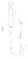
- the catheterhaving a mapping assembly at its distal end.
- the cathetercomprises an elongated catheter body 12 having proximal and distal ends. a control handle 16 at the proximal end of the catheter body, and a mapping assembly 17 mounted at the distal end of the catheter body.
- the catheter body 12includes an elongated proximal shaft 13 at its proximal end and a shorter distal shaft 14 at its distal end.
- the proximal shaft 13comprises an elongated tubular construction having a single, axial or central lumen 18 .
- the proximal shaft 13is flexible, i.e., bendable, but substantially non-compressible along its length.
- the proximal shaft 13can be of any suitable construction and made of any suitable material.
- a presently preferred constructioncomprises an outer wall 20 made of polyurethane or PEBAX.
- the outer wall 20comprises an imbedded braided mesh of stainless steel or the like, as is generally known in the art, to increase torsional stiffness of the proximal shaft 13 so that, when the control handle 16 is rotated, the distal shaft 14 will rotate in a corresponding manner.
- the outer diameter of the proximal shaft 13is not critical, but is preferably no more than about 8 french, more preferably 7 french. Likewise the thickness of the outer wall 20 is not critical, but is thin enough so that the central lumen 18 can accommodate any desired wires, cables and/or tubes.
- the inner surface of the outer wall 20is lined with a stiffening tube 21 to provide improved torsional stability.
- the outer diameter of the stiffening tube 21is about the same as or slightly smaller than the inner diameter of the outer wall 20.
- the stiffening tube 21can be made of any suitable material, such as polyimide, which provides very good stiffness and does not soften at body temperature.
- the distal shaft 14comprises a short section of tubing having four lumens, namely, a lead wire lumen 30, a contraction wire lumen 32, a support member lumen 34, and a deflection wire lumen 36.
- the tubing of the distal shaft 14is made of a suitable non-toxic material that is preferably more flexible than the proximal shaft 13 .
- a presently preferred material for the distal shaft tubingis braided polyurethane, i.e., polyurethane with an embedded mesh of braided stainless steel or the like.
- the size of each lumenis not critical, but is sufficient to house the components extending therethrough, as discussed further below.
- the useful length of the catheteri.e., that portion that can be inserted into the body excluding the mapping assembly 17, can vary as desired. Preferably the useful length ranges from about 110 cm to about 120 cm.
- the length of the distal shaft 14is a relatively small portion of the useful length, and preferably ranges from about 3.5 cm to about 10 cm, more preferably from about 5cm to about 6.5 cm.
- FIG. 2A preferred means for attaching the proximal shalt 13 to the distal shaft 14 is illustrated in FIG. 2.
- the proximal end of the distal shaft 14comprises an outer circumferential notch 23 that receives the inner surface of the outer wall 20 of the catheter body 12 .
- the distal shaft 14 and catheter body 12are attached by glue or the like.
- a spacer(not shown) can be provided within the proximal shaft 13 between the distal end of the stiffening tube 20 and the proximal end of the distal shaft 14 to provide a transition in flexibility at the junction of the proximal shaft and distal shaft, which allows the junction of the proximal and distal shafts to bend smoothly without folding or kinking.
- An example of such a spaceris described in more detail in U.S. Patent No. 5,964,757, the disclosure of which is incorporated herein by reference.
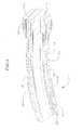
- the mapping assembly 17comprises a generally straight proximal region 38 and a generally circular main region 39.
- the proximal region 38is mounted on the distal shaft 14, as described in more detail below, so that its axis is generally parallel to the axis of the distal shaft.
- the proximal region 38preferably has an exposed length, e.g., not contained within the distal shaft 14, ranging from about 3 mm to about 12 mm, more preferably about 3 mm to about 8 mill, still more preferably about 5 mm inch, but can vary as desired.
- the generally circular main region 39is generally traverse to the catheter body 12.
- the generally circular main region 39is preferably generally perpendicular to the catheter body 12.
- the generally circular main region 39can form a flat circle or can be very slightly helical, as shown in FIG. 3.
- the main region 39has an outer diameter preferably ranging to about 10 mm to about 25 mm, more preferably about 12 mm to about 20 mm.
- the generally circular main region 39can curve in a clockwise direction or a counterclockwise direction.
- the mapping assembly 17is formed of a non-conductive cover 22, which is preferably generally tubular, but can have any cross-sectional shape as desired.
- the non-conductive cover 22can be made of any suitable material, and is preferably made of a biocompatible plastic such as polyurethane or PEBAX.
- the non-conductive cover 22can be pre-formed into the desired generally circular shape of the generally circular main region. Alternatively, the shape of the generally circular main region can be defined by a wire or other component extending through the non-conductive cover 22.
- a pre-formed support member 24extends through the non-conductive cover 22 to define the shape of the generally circular main region 39.
- the support member 24is made of a material having shape-memory, i.e., that can be straightened or bent out of its original shape upon exertion of a force and is capable of substantially returning to its original shape upon removal of the force.
- a particularly preferred material for the support member 24is a nickel/titanium alloy. Such alloys typically comprise about 55% nickel and 45% titanium, but may comprise from about 54% to about 57% nickel with the balance being titanium.
- a preferred nickel/titanium alloyis Nitinol, which has excellent shape memory, together with ductility, strength, corrosion resistance, electrical resistivity and temperature stability.
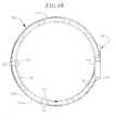
- a series of ring electrodes 26are mounted on the non-conductive cover 22 of the generally circular main region 39 of the mapping assembly 17 , as shown in FIGs. 4a and 4b.
- the ring electrodes 26can be made of any suitable solid conductive material, such as platinum or gold, preferably a combination of platinum and iridium, and mounted onto the non-conductive cover 22 with glue or the like.
- the ring electrodes 26can be formed by coating the non-conductive cover 22 with an electrically conducting material, like platinum, gold and/or iridium. The coating can be applied using sputtering, ion beam deposition or an equivalent technique.
- each ring electrode 26is mounted by first forming a hole in the non-conductive cover 22 .
- An electrode lead wire 50is fed through the hole, and the ring electrode 26 is welded in place over the lead wire and non-conductive cover 22 .
- the lead wires 50extend through the non-conductive cover 22 and into the catheter body 12.
- the proximal end of each lead wire 50is electrically connected to a suitable connector (not shown), which is connected an appropriate monitor or other device for receiving and displaying the information received from the ring electrodes 26.
- the number of ring electrodes 26 on the assemblycan vary as desired. Preferably the number of ring electrodes ranges nom about six to about twenty, more preferably from about eight to about twelve, in one embodiment, the assembly carries ten ring electrodes.
- the ring electrodes 26can be approximately evenly spaced around the generally circular main region 39 , as shown in FIG. 4a. In a particularly preferred embodiment, a distance of approximately 5 mm is provided between the centers of the ring electrodes 26.
- the mapping assembly 17includes a series of ring electrode pairs 25.
- Each ring electrode pair 25comprises two closely-spaced ring electrodes 26.
- the term "ring electrode pair”refers to a pair of ring electrodes that are arranged closer to each other than they are to the other adjacent ring electrodes.
- the distance between two electrodes 26 of an electrode pair 25is less than about 3 mm, more preferably less than about 2 mm, still more preferably from about 0.5 mm to about 1.5 mm.
- the number of electrode pairs 25can vary as desired, and preferably ranges from 6 to 14 pairs, more preferably 10 pairs.
- the mapping assemblycarries 10 pairs of electrodes with a space of approximately 1 mm between the two electrodes 26 of each pair 25.
- each ring electrode 26is relatively short, having a length ranging from about 0.4 mm to about 0.75 mm, with the most distal ring electrode 26c being longer than the other ring electrodes, preferably having a length ranging from about 1 mm to about 1.5 mm.
- the longer ring electrodeprovides a signal to the user when the catheter is being viewed under fluoroscopy.
- the mapping assemblyis generally circular, it can be difficult for the user to determine which electrodes are placed at a particular location in the heart. By having one ring electrode, such as the most distal ring electrode, sized differently from the other ring electrodes, the user has a reference point when viewing the catheter under fluoroscopy.
- the electrode pairs 25are preferably approximately evenly spaced around the generally circular main region 39.
- the closely-spaced electrode pairs 25allow for more accurate detection of near field pulmonary vein potential versus far field atrial signals, which is very important when trying to treat atrial fibrillation.
- the near field pulmonary vein potentialsare very small signals whereas the atria, located very close to the pulmonary vein, provides much larger signals. Accordingly, even when the mapping array is placed in the pulmonary vein, it can be difficult for the physician to determine whether the signal is a small, close potential (from the pulmonary vein) or a larger, farther potential (from the atria).
- Closely-spaced bipolespermit the physician to more accurately determine whether he is looking at a close signal or a far signal. Accordingly, by having closely-spaced electrodes, one is able to target exactly the locations of myocardial tissue that have pulmonary vein potentials and therefore allows the clinician to deliver therapy to the specific tissue. Moreover, the closely-spaced electrodes allow the physician to determine the exact anatomical location of the ostium by the electrical signal.
- additional electrodescould be mounted along the distal shaft 14 and/or the generally straight proximal section 39.
- a contraction wire 40is provided to contract the generally circular main region 39 to thereby reduce its diameter.
- the contraction wire 40has a proximal end anchored in the control handle 16, which is used to manipulate the contraction wire as described further below.
- the contraction wire 40extends through the central lumen 18 of the proximal shaft 13, through the contraction wire lumen 32 of the distal shaft 14 and into the non-conductive cover 22.
- the portion of the contraction wire 40 extending through the non-conductive cover 22is positioned on the side of the generally circular main region 39 closer to the center of the generally circular main region, as best shown in FIGS. 5 and 6.
- the center of the generally circular main regionrefers to the center of the circle formed by the generally circular main region.
- the contraction wire 40extends through a plastic tube 42.
- the plastic tube 42comprise three layers, including an inner layer of polyimide over which a braided layer is formed, the braided layer comprising a braided stainless steel mesh or the like, as is generally known in the art.
- the braided layerenhances the strength of the plastic tube 42, reducing the tendency for the contraction wire 40 to straighten the preformed curve of the mapping assembly.
- a thin plastic layer of polytetrafluoroethyleneis provided over the braided layer to protect the braided layer from getting tangled with the lead wires 50 within the non-conductive cover 22 .
- the plastic tube 42has a proximal end anchored to the distal end of the distal shaft 14.
- the support member 24extends through the plastic tube 42 with the contraction wire 40.
- the distal ends of the support member 24 and the contraction wire 40are soldered or otherwise attached to a small stainless steel tube 44.
- the retative positions of the contraction wire 40 and the support member 24can be controlled so that the contraction wire 40 can be positioned on the side of the generally circular region closer to the center of the generally circular region, as described above.
- the contraction wire 40 on the inside of the curvepulls the support member 24 to the inside of the curve, enhancing contraction of the generally circular region 39.
- the plastic tube 42includes a braided layer, it keeps the contraction wire 40 from tearing through the non-conductive cover 22.
- a first compression coil 46is situated within the proximal shaft 13 and distal shaft 14 in surrounding relation to the contraction wire 40.
- the first compression coil 46extends from the proximal end of the proximal shaft 13 and through the contraction wire lumen 32.
- the first compression coil 46is made of any suitable metal, preferably stainless steel, and is tightly wound on itself to provide flexibility, i.e., bending, but to resist compression.
- the inner diameter of the first compression coil 46is preferably slightly larger than the diameter of the contraction wire 40.
- the outer surface of the first compression coil 46is covered by a flexible, non-conductive sheath 68, e.g., made of polyimide tubing.
- the first compression coil 46preferably is formed of a wire having a square or rectangular cross-sectional area, which makes it less compressible than a compression coil formed from a wire having a circular cross-sectional area. As a result, the first compression coil 46 keeps the catheter body 12, and particularly the distal shaft 14, from deflecting when the contraction wire 40 is manipulated to contract the mapping assembly 17 as it absorbs more of the compression.
- the first compression coil 46is anchored at its proximal end to the outer wall 20 of the catheter body 12 by proximal glue joint 70 and to the distal shaft 14 by distal glue joint 72.
- Both glue joints 70 and 72preferably comprise polyurethane glue or the like.
- the gluemay be applied by means of a syringe or the like through a hole made between the outer surface of the catheter body 12 and the central lumen 18. Such a hole may be formed, for example, by a needle or the like that punctures the outer wall 20 of the catheter body 12 which is heated Sufficiently to form a permanent hole.
- the glueis then introduced through the hole to the outer surface of the first compression coil 46 and wicks around the outer circumference to form a glue joint about the entire circumference of the compression coil.
- the distal out of the mapping assembly 17is sealed closed with a dome 54 of polyurethane glue or the like.
- a short ring 56made or metal or plastic, and preferably polyamide, is mounted within the distal end of the non-conductive cover 22. The short ring 56 prevents the distal end of the non-conductive cover 22 from collapsing, there by maintaining the diameter of the non-conductive cover at its distal end.
- the non-conductive cover 22is attached to the distal shaft by glue or the like.
- the plastic tube 42has its proximal end inserted and glued in the distal end of the distal shaft 14.
- the glue from the plastic tube 42can further serve to anchor the distal end of the first compression coil 46 in place within the contraction wire lumen 32.
- the support member 24extends from the support member lumen 32 into the plastic tube 42 within the non-conductive cover 22.
- the proximal end of the support member 24terminates a short distance within the support member lumen 34, approximately about 5 mm, so as not to adversely affect the ability of the distal shaft 14 to deflect. However, if desired, the proximal end of the support member 24 can extend further into the catheter body 12.
- the lead wires 50 attached to the ring electrodes 26extend through the lead wire lumen 30 of the distal shaft 14, through the central lumen 18 of the catheter body 12 , and the control handle 16, and terminate at their proximal end in a connector (not shown).
- the portion of the lead wires 50 extending through the central lumen 18 of the catheter body 12 , control handle 16 and proximal end of the distal shaft 14are enclosed within a protective sheath 52 , which can be made of any suitable material, preferably polyimide.
- the protective sheath 52is anchored at its distal end to the proximal end of the distal shaft 14 by gluing it in the lead wire lumen 30 with polyurethane glue or the like.
- a deflection wire 64is provided for deflection of the distal shaft 14 .
- the deflection wire 64extends through the proximal shaft 13, and is anchored at its proximal end to the control handle 16 and at its distal end to the distal shaft 14.
- the deflection wire 64is made of any suitable metal, such as stainless steel or Nitinol, and is preferably coated with Teflon® or the like. The coating imparts lubricity to the puller wire 64.
- the puller wire 64preferably has a diameter ranging from about 0.006 to about 0.0 10 inch.
- the deflection wire 64extends into the deflection wire lumen 36 of the distal shaft 14.
- the deflection wire 64is anchored at its distal end to the sidewall of the distal shaft 14, as is generally described in U.S. Patent No. 6,371,955, the disclosure of which is incorporated herein by reference.
- a second compression coil 66is situated within the proximal shaft 13 in surrounding relation to the deflection wire 64.
- the second compression coil 66extends from the proximal end of the proximal shaft 13 to the distal end of the proximal shaft.
- the second compression coil 66is made of any suitable metal, preferably stainless steel, and is tightly wound on itself to provide flexibility, i.e., bending, but to resist compression.
- the inner diameter of the second compression coil 66is preferably slightly larger than the diameter of the deflection wire 64 .
- the Teflon® coating on the deflection wire 64allows it to slide freely within the second compression coil 66.
- the outer surface of the second compression coil 66is also covered by a flexible, non-conductive sheath 68, e.g., made of polyimide tubing.
- the second compression coil 66is anchored at its proximal end to the outer wall 20 of the catheter body 12 by the proximal glue joint 70 and to the distal shaft 14 by the distal glue joint 72.
- the deflection wire 64 and second compression coil 66extends through a plastic, preferably Teflon®, puller wire sheath 71, which prevents the puller wire 64 from cutting into the wall of the distal shaft when the distal shaft is deflected.
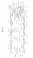
- the catheterincludes a control handle 16 as shown in FIGs. 8 to 10.
- the control handle 16includes a handle body 74 in which a core 76 is fixedly mounted.
- the corehas a generally cylindrical distal region 75 and a generally cylindrical proximal region 77 having a larger diameter than the proximal region.
- a piston 82is slidably mounted over the distal region 77 of the core 76.
- the proximal end of the piston 82is maintained within the handle body 74, and the distal end of the piston extends outside the handle body
- a thumb knob 84is mounted in surrounding relation to a portion of the distal end of the piston 82 so that the user can more easily move the piston longitudinally relative to the core 76 and handle body 74.
- the proximal end of the catheter body 12is fixedly mounted to the distal end of the piston 82 through a tip portion 78 that is mounted on the distal end of the piston.
- the proximal end of the catheter body 12is inserted into an axial passage 80 in the tip portion and optionally glued in place.
- the pistonincludes an axial passage 86 in communication with the axial passage 80 of the tip portion 78, and the core 76 includes an axial passage 88 in communication with the axial passage in the piston.
- the lead wires 50, contraction wire 46 and deflection wire 66 that extend through the catheter body 12extend out the proximal end of the catheter body and through the axial passages in the tip portion 78, piston 82 and core 76.
- the lead wires 50can extend out the proximal end of the control handle 16 or can be connected to a connector (not shown) that is incorporated into the control handle, as is generally known in the art.
- the proximal end of the deflection wire 64is anchored to the core 76.
- the portion of the axial passage 88 extending through the proximal region 77 of the core 76has a larger diameter than the portion of the axial passage extending through the distal region 75 of the core 76.
- a deflection wire adjuster 90is adjustably mounted, as described further below, in a portion of the axial passage 88 near the distal end of the proximal region 77 of the core 76.
- the deflection wire adjuster 90has an opening 92 extending therethrough in a direction generally perpendicular to the axial passage 88 of the core 76.
- the deflection wire 64extends through the opening 92 in the deflection wire adjuster 90 such that the deflection wire changes directions.
- the proximal end of the deflection wire 64is then anchored to the core 76.
- the distal region 77 of the core 76includes a generally rectangular opening 94 that extends generally parallel to the axial passage 88 of the core.
- a channel 96connects the proximal end of the generally rectangular opening 94 to the distal end of the portion of the axial passage 88 in the proximal region 75 of the core 76.
- the proximal end of the deflection wire 64extends through the channel 96 and into the generally rectangular opening 94 .
- a deflection wire anchor 98which can comprise a short piece of hypodermic stock.
- the deflection wire anchor 98has a diameter greater than the width of the channel 96 and thus prevents the proximal end of the deflection wire 64 from being pulled through the channel, thereby anchoring the deflection wire to the core 76.
- the piston 82is moved distally relative to the handle body 74 and core 76, thereby pulling the catheter body 12 distally relative to the deflection wire 64, which is anchored to the core.
- the deflection wire 64pulls on the side of the distal shaft 14 to which it is anchored, thereby deflecting the distal shaft in that direction.
- the piston 82is moved proximally back to its original position relative to the handle body 74 and core 76.
- Manipulation of the deflection wire adjuster 90adjusts the amount of free play in the deflection wire 64 .
- the deflection wire adjuster 90is adjustahly mounted in a portion of the axial passage 88 near the distal end of the proximal region 77 of the core 76.
- the portion of the axial passage 88 in which the deflection wire adjuster 90 is mountedincludes a series of ridges 100 extending along the surface of the core 76, with the ridges being generally perpendicular to the axis of the core.
- the deflection wire adjuster 90carries an outwardly extending tab 102 that fits in the spaces between the ridges 100.
- the deflection wire adjuster 90can be moved along the length of the core 76 and snapped into place by placing the tab 102 between two ridges 100. As the deflection wire adjuster 90 is moved proximally (away from catheter body 12) less free play is provided for the deflection wire 64.
- the precise mechanism for adjusting the amount of free play of the deflection wire 64is not critical, and alternative mechanisms can be provided. Alternatively, the deflection wire 64 can be anchored directly to the core 76 so that it is not adjustable.
- the control handle 16is also used for longitudinal movement of the contraction wire 40.
- the contraction wire 40extends from the catheter body 12, through the axial passage 86 in the piston 82 and through the axial passage 88 within the distal region 75 of the core 76.
- the proximal end of the contraction wire 40is anchored to a contraction wire adjuster 104 that is slidably mounted in the core 76 .
- the contraction wire adjuster 104is generally rectangular having a bottom region 108 that extends downward through a slot 110 in the proximal region 77 of the core 76, the slot being in commumcation with the axial passage 88 of the core.
- the proximal end of the contraction wire 40which, as noted above, extends through the axial passage 88 . is anchored in the contraction wire adjuster 104 in a manner very similar to the manner in which the deflection wire 64 is anchored to the core 76 . as described above. Spccifically, a contraction wire anchor 108.
- the contraction wire anchor 98has a diameter greater than the width of the channel 112 and thus prevents the proximal end of the contraction wire 40 from being pulled through the channel, thereby anchoring the contraction wire to the contraction wire adjuster 104.
- the distal end of the contraction wire adjuster 104is adjustably attached to a cam receiver 106.
- the cam receiver 106is generally tubular, having a short slot 114 extending from its proximal end sized to receive the distal end of the contraction wire adjuster 104.
- the cam receiver 106is slidably mounted over the piston 82 and the distal region 75 of the core 76 with the bottom portion of the contraction wire adjuster 104 positioned in the slot 114 in the core and a corresponding slot 115 in the piston.
- the top of the distal end of the contraction wire adjuster 104includes a series of outwardly extending teeth 116 that mate with a plurality of notches 118 within the slot 114 of the cam receiver 106 so that the contraction wire adjuster can be snapped into the cam receiver.
- the position of the contraction wire adjuster 104 relative to the cam receiver 106can be longitudinally adjusted by repositioning the teeth 116 rotative to the notches 118 , to thereby adjust the tension on the contraction wire 40 .
- the cam 120includcs a ramped proximal surface 122.
- the cam receiver 106includes a ramped distal surface 123 and an outwardly extending tab 124 at the most distal point of the ramped distal surface.
- the tab 124contacts the ramped proximal surface 122 of the cam 120
- the ramped proximal surface 112correspondingly rotates and pushes the cam receiver 104 proximally relative to the core 76 and catheter body 12.
- the contraction wire 40is pulled proximally to thereby contract the generally circular main region 39 of the mapping assembly 17 .
- the ramped proximal surface 122 of the cam 120includes an outwardly extending tab 126 at its most proximal point.
- the tab 124 on the cam receiver 104contacts the tab 126 on the ramped proximal surface 122, thereby prohibiting further rotation of the cam relative to the cam receiver.
- the tab 126 on the ramped proximal surface 122pushes the tab 124 on the cam receiver 104 such that the cam receiver moves distally, thereby releasing the tension on the contraction wire 40 so that the generally circular main region 39 of the mapping assembly 17 returns to its original configuration.
- the direction of the ramped proximal surface 122can be changed so that clockwise rotation of the cam 120 causes contraction of generally circular main region 39 of the mapping assembly 17 and counterclockwise rotation causes it to return to its original configuration.
- a flexible grip 128is provided over the cam 120 for the user to more easily and comfortably rotate the cam 120.
- a suitable guiding sheathis inserted into the patient with its distal end positioned at a desired mapping location.
- An example of a suitable guiding sheath for use in connection with the present inventionis the PrefaceTM Braiding Guiding Sheath, commercially available from Biosense Webster, Inc. (Diamond Bar, California).
- the distal end of the sheathis guided into one of the atria.
- a catheter in accordance with the present inventionis fed through the guiding sheath until its distal end extends out of the distal end of the guiding sheath.
- the mapping assembly 17is straightened to fit through the sheath.
- mapping assembly 17is then inserted into a pulmonary vein or other tubular region (such as the coronary sinus, superior vena cava, or inferior vena cava) SO that the outer circumference of the generally circular main region 39 of the assembly is in contact with a circumference inside the tubular region.
- a pulmonary vein or other tubular regionsuch as the coronary sinus, superior vena cava, or inferior vena cava
- the outer circumference of the generally circular main region 39 of the assemblyis in contact with a circumference inside the tubular region.
- at least about 50%, more preferably at least about 70%, and still more preferably at least about 80% of the circumference of the generally circular main regionis in contact with a circumference inside the tubular region.
- the circular arrangement of the electrodes 26permits measurement of the electrical activity at that circumference of the tubular structure so that ectopic beats between the electrodes can be identified.
- the size of the generally circular main region 39permits measurement of electrical activity along a diameter of a pulmonary vein or other tubular structure of or near the heart because the circular main region has a diameter generally corresponding to that of a pulmonary vein or the coronary sinus.
Landscapes
- Health & Medical Sciences (AREA)
- Life Sciences & Earth Sciences (AREA)
- Biomedical Technology (AREA)
- Molecular Biology (AREA)
- Veterinary Medicine (AREA)
- Biophysics (AREA)
- Pathology (AREA)
- Engineering & Computer Science (AREA)
- Public Health (AREA)
- Heart & Thoracic Surgery (AREA)
- Medical Informatics (AREA)
- Physics & Mathematics (AREA)
- Surgery (AREA)
- Animal Behavior & Ethology (AREA)
- General Health & Medical Sciences (AREA)
- Physiology (AREA)
- Cardiology (AREA)
- Media Introduction/Drainage Providing Device (AREA)
- Measurement And Recording Of Electrical Phenomena And Electrical Characteristics Of The Living Body (AREA)
Abstract
Description
Claims (12)
- A mapping catheter comprising:an elongated tubular catheter body having an outer wall and proximal and distalends;a mapping assembly at the distal end of the catheter body, the mapping assemblycomprising:a tubular structure comprising a pre-formed generally circular main regiongenerally transverse and distal to the catheter body and having an outer circumference,wherein the tubular structure comprises a non-conductive cover over at least the mainregion of the mapping assembly, anda plurality of electrodes carried by the generally circular main region of themapping assembly;a control handle mounted at the proximal end of the catheter body; anda contraction wire extending through the catheter body and non-conductive coverof the mapping assembly for contracting the generally circular main region of the mappingassembly, the contraction wire having a distal end anchored in the non-conductive coverand a proximal end anchored to a mechanism in the control handle that facilitateslongitudinal movement of the contraction wire relative to the catheter body, wherein theportion of the contraction wire extending through the non-conductive cover is positionedon the side of the generally circular main region closer to the center of the generallycircular region.
- A catheter according to claim 1, wherein the portion of the contraction wireextending through the non-conductive cover extends through a plastic tube.
- A catheter according to claim 2, wherein the plastic tube comprisespolyimide.
- A catheter according to claim 2, wherein the plastic tube comprises apolyimide layer and a braided metal layer over the polyimide layer.
- A catheter according to claim 1, wherein the mapping assembly furthercomprises a pre-formed support member having at least a portion extending through thenon-conductive cover.
- A catheter according to claim 5, wherein the pre-formed support membercomprises nitinol.
- A catheter according to claim 5, wherein the portion of the contraction wireand the portion of the pre-formed support member extending through the non-conductivecover extend through a plastic tube.
- A catheter according to claim 7, wherein the plastic tube comprisespolyimide.
- A catheter according to claim 7, wherein the plastic tube comprises apolyimide layer and a braided metal layer over the polyimide layer.
- A catheter according to claim 7, wherein the contraction wire and the pre-formedsupport member each have a distal end anchored to a metal tube.
- A catheter according to claim 7, wherein the portion of the contraction wireextending through the non-conductive cover is positioned closer than the support memberto the center of the generally circular region.
- A mapping catheter comprising:an elongated tubular catheter body having an outer wall and proximal and distalends;a mapping assembly at the distal end of the catheter body, the mapping assemblycomprising:a tubular structure comprising a pre-formed generally circular main regiongenerally transverse and distal to the catheter body and having an outer circumference,wherein the tubular structure comprises a non-conductive cover over at least the main region of the mapping assembly and a pre-formed support member extending through aplastic tube that extends through the non-conductive cover, anda plurality of electrodes carried by the generally circular main region of themapping assembly;a control handle mounted at the proximal end of the catheter body;a contraction wire extending through the catheter body and through the plastic tubewithin non-conductive cover of the mapping assembly for contracting the generallycircular main region of the mapping assembly, the contraction wire having a distal endanchored in the non-conductive cover and a proximal end anchored to a mechanism in thecontrol handle that facilitates longitudinal movement of the contraction wire relative to thecatheter body, wherein the portion of the contraction wire extending through the non-conductivecover is positioned on the side of the generally circular main region closer tothe center of the generally circular region; anda deflection wire extending through the catheter body, the deflection wire having adistal end fixedly attached to the catheter body near the catheter body's distal end and aproximal end anchored to a mechanism in the control handle that facilitates longitudinalmovement of the deflection wire relative to the catheter body.
Applications Claiming Priority (2)
| Application Number | Priority Date | Filing Date | Title |
|---|---|---|---|
| US386872 | 1982-06-10 | ||
| US10/386,872US7142903B2 (en) | 2003-03-12 | 2003-03-12 | Catheter with contractable mapping assembly |
Publications (3)
| Publication Number | Publication Date |
|---|---|
| EP1457225A2true EP1457225A2 (en) | 2004-09-15 |
| EP1457225A3 EP1457225A3 (en) | 2005-04-20 |
| EP1457225B1 EP1457225B1 (en) | 2007-10-31 |
Family
ID=32771601
Family Applications (1)
| Application Number | Title | Priority Date | Filing Date |
|---|---|---|---|
| EP04251415AExpired - LifetimeEP1457225B1 (en) | 2003-03-12 | 2004-03-11 | Catheter with contractable mapping assembly |
Country Status (4)
| Country | Link |
|---|---|
| US (5) | US7142903B2 (en) |
| EP (1) | EP1457225B1 (en) |
| JP (1) | JP4468022B2 (en) |
| DE (1) | DE602004009720T2 (en) |
Cited By (8)
| Publication number | Priority date | Publication date | Assignee | Title |
|---|---|---|---|---|
| EP2022397A1 (en)* | 2007-08-08 | 2009-02-11 | ProRhythm, Inc. | Miniature circular mapping catheter |
| WO2010006229A1 (en)* | 2008-07-11 | 2010-01-14 | Boston Scientific Scimed, Inc. | Miniature circular mapping catheter |
| US7860578B2 (en) | 2007-08-08 | 2010-12-28 | Boston Scientific Scimed, Inc. | Miniature circular mapping catheter |
| EP2289408A1 (en)* | 2009-08-28 | 2011-03-02 | Biosense Webster, Inc. | Catheter with multi-functional control handle having rotational mechanism |
| CN102551705A (en)* | 2012-01-19 | 2012-07-11 | 赖珩莉 | Auricular tachycardia mapping catheter and preparation method thereof |
| US8747351B2 (en) | 2009-08-28 | 2014-06-10 | Biosense Webster, Inc. | Catheter with multi-functional control handle having linear mechanism |
| US9545495B2 (en) | 2010-06-25 | 2017-01-17 | Smiths Medical Asd, Inc. | Catheter assembly with seal member |
| US11207495B2 (en) | 2010-06-25 | 2021-12-28 | Smiths Medical Asd, Inc. | Catheter assembly with seal member |
Families Citing this family (66)
| Publication number | Priority date | Publication date | Assignee | Title |
|---|---|---|---|---|
| US7142903B2 (en) | 2003-03-12 | 2006-11-28 | Biosense Webster, Inc. | Catheter with contractable mapping assembly |
| WO2005053555A1 (en)* | 2003-12-01 | 2005-06-16 | Biotronik Crm Patent Ag | Electrode catheter for the electrotherapy of cardiac tissue |
| US7412273B2 (en)* | 2004-11-15 | 2008-08-12 | Biosense Webster, Inc. | Soft linear mapping catheter with stabilizing tip |
| WO2006083881A1 (en)* | 2005-01-31 | 2006-08-10 | Medtronic, Inc. | Method of manufacturing a medical lead |
| US8292827B2 (en) | 2005-12-12 | 2012-10-23 | Boston Scientific Scimed, Inc. | Micromachined medical devices |
| US8172758B2 (en)* | 2006-03-06 | 2012-05-08 | Imacor Inc. | Transesophageal ultrasound probe with an adaptive bending section |
| US11389232B2 (en) | 2006-06-28 | 2022-07-19 | Kardium Inc. | Apparatus and method for intra-cardiac mapping and ablation |
| US9119633B2 (en) | 2006-06-28 | 2015-09-01 | Kardium Inc. | Apparatus and method for intra-cardiac mapping and ablation |
| US20080058765A1 (en)* | 2006-08-31 | 2008-03-06 | Pierri Jais | Catheter for linear and circular mapping |
| US8043288B2 (en)* | 2006-12-28 | 2011-10-25 | St. Jude Medical, Atrial Fibrillation Division, Inc. | Virtual electrode ablation catheter with electrode tip and variable radius capability actuated with at least one rack and pinion mechanisms |
| CA2676119C (en) | 2007-01-29 | 2021-01-19 | Simon Fraser University | Transvascular nerve stimulation apparatus and methods |
| US8906011B2 (en) | 2007-11-16 | 2014-12-09 | Kardium Inc. | Medical device for use in bodily lumens, for example an atrium |
| US8712550B2 (en) | 2008-12-30 | 2014-04-29 | Biosense Webster, Inc. | Catheter with multiple electrode assemblies for use at or near tubular regions of the heart |
| US8808345B2 (en) | 2008-12-31 | 2014-08-19 | Medtronic Ardian Luxembourg S.A.R.L. | Handle assemblies for intravascular treatment devices and associated systems and methods |
| US8287532B2 (en) | 2009-04-13 | 2012-10-16 | Biosense Webster, Inc. | Epicardial mapping and ablation catheter |
| US8562890B2 (en)* | 2010-01-25 | 2013-10-22 | Apple Inc. | Method for molding a cable structure |
| US20110213260A1 (en)* | 2010-02-26 | 2011-09-01 | Pacesetter, Inc. | Crt lead placement based on optimal branch selection and optimal site selection |
| US8556664B2 (en)* | 2010-04-20 | 2013-10-15 | Apple Inc. | Plug assembly with core structural member |
| IN2014MN01970A (en) | 2012-03-05 | 2015-07-03 | Univ Fraser Simon | |
| US10827977B2 (en) | 2012-05-21 | 2020-11-10 | Kardium Inc. | Systems and methods for activating transducers |
| US9017321B2 (en) | 2012-05-21 | 2015-04-28 | Kardium, Inc. | Systems and methods for activating transducers |
| US9198592B2 (en) | 2012-05-21 | 2015-12-01 | Kardium Inc. | Systems and methods for activating transducers |
| EP2863987B1 (en) | 2012-06-21 | 2023-08-02 | Lungpacer Medical Inc. | Transvascular diaphragm pacing systems |
| JP5729778B2 (en) | 2013-01-30 | 2015-06-03 | 日本ライフライン株式会社 | Electrode catheter |
| CN105873630B (en) | 2013-11-22 | 2020-01-03 | 隆佩瑟尔医疗公司 | Device and method for assisted respiration by transvascular nerve stimulation |
| JP2015112114A (en)* | 2013-12-06 | 2015-06-22 | 株式会社グッドマン | Catheter for measuring nerve potential |
| AU2015208640B2 (en) | 2014-01-21 | 2020-02-20 | Lungpacer Medical Inc. | Systems and related methods for optimization of multi-electrode nerve pacing |
| CN103784181A (en)* | 2014-03-06 | 2014-05-14 | 山东威高集团医用高分子制品股份有限公司 | single-use monopolar probe |
| US10722184B2 (en) | 2014-11-17 | 2020-07-28 | Kardium Inc. | Systems and methods for selecting, activating, or selecting and activating transducers |
| US10368936B2 (en) | 2014-11-17 | 2019-08-06 | Kardium Inc. | Systems and methods for selecting, activating, or selecting and activating transducers |
| US11534239B2 (en) | 2014-12-22 | 2022-12-27 | Biosense Webster (Israel) Ltd. | Systems and method or uses of ablating cardiac tissue |
| CN104771162A (en)* | 2015-05-04 | 2015-07-15 | 中国人民解放军总医院 | Heart electricity information mapping electrode |
| US20160338769A1 (en) | 2015-05-18 | 2016-11-24 | Biosense Webster (Israel) Ltd. | Catheter with anchoring balloon assembly |
| US10905329B2 (en) | 2016-06-09 | 2021-02-02 | Biosense Webster (Israel) Ltd. | Multi-function conducting elements for a catheter |
| WO2018064070A1 (en)* | 2016-09-27 | 2018-04-05 | Cardiac Pacemakers, Inc. | Mapping and/or ablation catheter with a closed distal loop |
| US11400205B2 (en) | 2016-11-23 | 2022-08-02 | Biosense Webster (Israel) Ltd. | Balloon-in-balloon irrigation balloon catheter |
| US10828091B2 (en) | 2016-12-28 | 2020-11-10 | Biosense Webster (Israel) Ltd. | Catheter with tapered support member for variable arcuate distal assembly |
| US10918832B2 (en) | 2017-03-27 | 2021-02-16 | Biosense Webster (Israel) Ltd | Catheter with improved loop contraction and greater contraction displacement |
| GB2561167A (en)* | 2017-03-30 | 2018-10-10 | Creo Medical Ltd | Electrosurgical energy conveying structure and electrosurgical device incorporating the same |
| US10293164B2 (en) | 2017-05-26 | 2019-05-21 | Lungpacer Medical Inc. | Apparatus and methods for assisted breathing by transvascular nerve stimulation |
| US12029545B2 (en) | 2017-05-30 | 2024-07-09 | Biosense Webster (Israel) Ltd. | Catheter splines as location sensors |
| CN111163834A (en) | 2017-06-30 | 2020-05-15 | 隆佩瑟尔医疗公司 | Device for preventing, reducing and/or treating cognitive impairment |
| US10195429B1 (en) | 2017-08-02 | 2019-02-05 | Lungpacer Medical Inc. | Systems and methods for intravascular catheter positioning and/or nerve stimulation |
| US10940308B2 (en) | 2017-08-04 | 2021-03-09 | Lungpacer Medical Inc. | Systems and methods for trans-esophageal sympathetic ganglion recruitment |
| US20190175908A1 (en) | 2017-12-11 | 2019-06-13 | Lungpacer Medical Inc. | Systems and methods for strengthening a respiratory muscle |
| JP2022500160A (en) | 2018-09-14 | 2022-01-04 | バイオセンス・ウエブスター・(イスラエル)・リミテッドBiosense Webster (Israel), Ltd. | Systems and methods or uses for ablating heart tissue |
| WO2020053831A1 (en) | 2018-09-14 | 2020-03-19 | Biosense Webster (Israel) Ltd. | Systems for ablating cardiac tissue |
| US11071585B2 (en) | 2018-09-14 | 2021-07-27 | Biosense Webster (Israel) Ltd. | Systems and methods of ablating cardiac tissue |
| EP4548964A1 (en) | 2018-11-08 | 2025-05-07 | Lungpacer Medical Inc. | Stimulation systems and related user interfaces |
| WO2020232333A1 (en) | 2019-05-16 | 2020-11-19 | Lungpacer Medical Inc. | Systems and methods for sensing and stimulation |
| WO2020252037A1 (en) | 2019-06-12 | 2020-12-17 | Lungpacer Medical Inc. | Circuitry for medical stimulation systems |
| US12004878B2 (en) | 2019-07-03 | 2024-06-11 | Biosense Webster (Israel) Ltd. | Composite catheter with single axial sensors and ring electrodes and related methods |
| US12220541B2 (en)* | 2019-07-03 | 2025-02-11 | Biosense Webster (Israel) Ltd. | Sensing and mapping catheter for guiding and supporting balloon catheter |
| US12369975B2 (en) | 2019-09-12 | 2025-07-29 | Biosense Webster (Israel) Ltd. | Balloon catheter with force sensor |
| US11633228B2 (en) | 2019-10-04 | 2023-04-25 | Biosense Webster (Israel) Ltd. | Identifying pulmonary vein occlusion by dimension deformations of balloon catheter |
| US12369974B2 (en) | 2019-10-10 | 2025-07-29 | Biosense Webster (Israel) Ltd. | Touch indication of balloon-catheter ablation electrode via balloon surface temperature measurement |
| US12137967B2 (en) | 2019-11-12 | 2024-11-12 | Biosense Webster (Israel) Ltd. | Accurate positioning and shape visualization of balloon catheter ablation tags |
| US12239364B2 (en) | 2020-10-07 | 2025-03-04 | Biosense Webster (Israel) Ltd. | Printed proximal electrodes of an expandable catheter for use as a common electrode |
| US11974803B2 (en) | 2020-10-12 | 2024-05-07 | Biosense Webster (Israel) Ltd. | Basket catheter with balloon |
| US11957852B2 (en) | 2021-01-14 | 2024-04-16 | Biosense Webster (Israel) Ltd. | Intravascular balloon with slidable central irrigation tube |
| US11849995B2 (en) | 2021-02-18 | 2023-12-26 | Biosense Webster (Israel) Ltd. | Detection of balloon catheter tissue contact using optical measurement |
| IL307916A (en) | 2021-04-26 | 2023-12-01 | Pulse Biosciences Inc | Circumferential ablation devices and methods |
| US20230008044A1 (en) | 2021-07-09 | 2023-01-12 | Biosense Webster (Israel) Ltd. | Pulsed field ablation catheter |
| CN116158833A (en)* | 2021-11-24 | 2023-05-26 | 杭州德诺电生理医疗科技有限公司 | Ablation system |
| US20230226638A1 (en) | 2022-01-20 | 2023-07-20 | Biosense Webster (Israel) Ltd. | Intravascular device including high voltage coaxial conductor wiring |
| EP4338695A1 (en) | 2022-09-11 | 2024-03-20 | Biosense Webster (Israel) Ltd. | System for combined ablation modalities |
Family Cites Families (76)
| Publication number | Priority date | Publication date | Assignee | Title |
|---|---|---|---|---|
| US4203430A (en)* | 1976-12-16 | 1980-05-20 | Nagashige Takahashi | Device for controlling curvature of an end section in an endoscope |
| US4207873A (en)* | 1977-05-16 | 1980-06-17 | American Cystoscope Makers, Inc. | Endoscope deflection control |
| US4882777A (en)* | 1987-04-17 | 1989-11-21 | Narula Onkar S | Catheter |
| US4920980A (en)* | 1987-09-14 | 1990-05-01 | Cordis Corporation | Catheter with controllable tip |
| US4777955A (en)* | 1987-11-02 | 1988-10-18 | Cordis Corporation | Left ventricle mapping probe |
| US4984581A (en)* | 1988-10-12 | 1991-01-15 | Flexmedics Corporation | Flexible guide having two-way shape memory alloy |
| US4960134A (en)* | 1988-11-18 | 1990-10-02 | Webster Wilton W Jr | Steerable catheter |
| DE69019509T2 (en)* | 1990-03-30 | 1996-02-15 | Pacesetter Ab | Device for positioning an electrode. |
| US5646030A (en)* | 1990-06-21 | 1997-07-08 | President And Fellows Of Harvard College | Method for isolating mutant cells |
| US5383923A (en)* | 1990-10-20 | 1995-01-24 | Webster Laboratories, Inc. | Steerable catheter having puller wire with shape memory |
| US5156151A (en) | 1991-02-15 | 1992-10-20 | Cardiac Pathways Corporation | Endocardial mapping and ablation system and catheter probe |
| US5275162A (en)* | 1991-11-08 | 1994-01-04 | Ep Technologies, Inc. | Valve mapping catheter |
| US5327905A (en)* | 1992-02-14 | 1994-07-12 | Boaz Avitall | Biplanar deflectable catheter for arrhythmogenic tissue ablation |
| US5354297A (en)* | 1992-02-14 | 1994-10-11 | Boaz Avitall | Biplanar deflectable catheter for arrhythmogenic tissue ablation |
| US5263493A (en)* | 1992-02-24 | 1993-11-23 | Boaz Avitall | Deflectable loop electrode array mapping and ablation catheter for cardiac chambers |
| EP0634907B1 (en)* | 1992-04-10 | 1997-01-29 | Cardiorhythm | Intracardiac electrical potential reference catheter |
| US5255679A (en)* | 1992-06-02 | 1993-10-26 | Cardiac Pathways Corporation | Endocardial catheter for mapping and/or ablation with an expandable basket structure having means for providing selective reinforcement and pressure sensing mechanism for use therewith, and method |
| DE4304353A1 (en)* | 1992-10-24 | 1994-04-28 | Helmut Dipl Ing Wurster | Suturing device used in endoscopic surgical operations - has helical needle with fixed non-traumatic thread held and rotated by rollers attached to instrument head extended into patients body. |
| US5364351A (en)* | 1992-11-13 | 1994-11-15 | Ep Technologies, Inc. | Catheter steering mechanism |
| US5706809A (en)* | 1993-01-29 | 1998-01-13 | Cardima, Inc. | Method and system for using multiple intravascular sensing devices to detect electrical activity |
| ES2174875T3 (en)* | 1993-04-28 | 2002-11-16 | Biosense Webster Inc | ELECTROPHYSIOLOGICAL CATHETER WITH PRECURVED POINT. |
| US5462544A (en)* | 1993-05-05 | 1995-10-31 | Energy Life System Corporation | Continuous heart tissue mapping and lasing catheter |
| US5611777A (en)* | 1993-05-14 | 1997-03-18 | C.R. Bard, Inc. | Steerable electrode catheter |
| US5545200A (en)* | 1993-07-20 | 1996-08-13 | Medtronic Cardiorhythm | Steerable electrophysiology catheter |
| US5984909A (en)* | 1993-08-13 | 1999-11-16 | Daig Corporation | Coronary sinus catheter |
| US5423772A (en)* | 1993-08-13 | 1995-06-13 | Daig Corporation | Coronary sinus catheter |
| US5562619A (en)* | 1993-08-19 | 1996-10-08 | Boston Scientific Corporation | Deflectable catheter |
| CA2174129C (en)* | 1993-10-14 | 2004-03-09 | Sidney D. Fleischman | Electrode elements for forming lesion patterns |
| US5407513A (en) | 1993-10-14 | 1995-04-18 | The Procter & Gamble Company | Apparatus and process for cyclically accelerating and decelerating a strip of material |
| US5582609A (en)* | 1993-10-14 | 1996-12-10 | Ep Technologies, Inc. | Systems and methods for forming large lesions in body tissue using curvilinear electrode elements |
| US6129724A (en)* | 1993-10-14 | 2000-10-10 | Ep Technologies, Inc. | Systems and methods for forming elongated lesion patterns in body tissue using straight or curvilinear electrode elements |
| US5673695A (en)* | 1995-08-02 | 1997-10-07 | Ep Technologies, Inc. | Methods for locating and ablating accessory pathways in the heart |
| WO1995010225A1 (en) | 1993-10-15 | 1995-04-20 | Ep Technologies, Inc. | Multiple electrode element for mapping and ablating |
| AU680569B2 (en)* | 1993-11-10 | 1997-07-31 | Cardiorhythm | Electrode array catheter |
| US5730127A (en)* | 1993-12-03 | 1998-03-24 | Avitall; Boaz | Mapping and ablation catheter system |
| US5487385A (en)* | 1993-12-03 | 1996-01-30 | Avitall; Boaz | Atrial mapping and ablation catheter system |
| US5882333A (en)* | 1994-05-13 | 1999-03-16 | Cardima, Inc. | Catheter with deflectable distal section |
| US5617854A (en)* | 1994-06-22 | 1997-04-08 | Munsif; Anand | Shaped catheter device and method |
| US5680860A (en)* | 1994-07-07 | 1997-10-28 | Cardiac Pathways Corporation | Mapping and/or ablation catheter with coilable distal extremity and method for using same |
| US5797905A (en)* | 1994-08-08 | 1998-08-25 | E. P. Technologies Inc. | Flexible tissue ablation elements for making long lesions |
| US5836947A (en)* | 1994-10-07 | 1998-11-17 | Ep Technologies, Inc. | Flexible structures having movable splines for supporting electrode elements |
| US5656030A (en)* | 1995-05-22 | 1997-08-12 | Boston Scientific Corporation | Bidirectional steerable catheter with deflectable distal tip |
| US6090104A (en)* | 1995-06-07 | 2000-07-18 | Cordis Webster, Inc. | Catheter with a spirally wound flat ribbon electrode |
| US5823955A (en)* | 1995-11-20 | 1998-10-20 | Medtronic Cardiorhythm | Atrioventricular valve tissue ablation catheter and method |
| US5755760A (en)* | 1996-03-11 | 1998-05-26 | Medtronic, Inc. | Deflectable catheter |
| US5997526A (en)* | 1996-03-25 | 1999-12-07 | The Uab Research Foundation | Shape memory catheter |
| US5800428A (en)* | 1996-05-16 | 1998-09-01 | Angeion Corporation | Linear catheter ablation system |
| US5882346A (en)* | 1996-07-15 | 1999-03-16 | Cardiac Pathways Corporation | Shapable catheter using exchangeable core and method of use |
| US5826576A (en)* | 1996-08-08 | 1998-10-27 | Medtronic, Inc. | Electrophysiology catheter with multifunction wire and method for making |
| US5779669A (en)* | 1996-10-28 | 1998-07-14 | C. R. Bard, Inc. | Steerable catheter with fixed curve |
| US6096036A (en)* | 1998-05-05 | 2000-08-01 | Cardiac Pacemakers, Inc. | Steerable catheter with preformed distal shape and method for use |
| US6002955A (en)* | 1996-11-08 | 1999-12-14 | Medtronic, Inc. | Stabilized electrophysiology catheter and method for use |
| US6088614A (en)* | 1997-03-31 | 2000-07-11 | Boston Scientific Corporation | Tissue characterization to identify an ablation site |
| US5879295A (en)* | 1997-04-02 | 1999-03-09 | Medtronic, Inc. | Enhanced contact steerable bowing electrode catheter assembly |
| US5827278A (en)* | 1997-05-20 | 1998-10-27 | Cordis Webster, Inc. | Deflectable tip electrode catheter with nylon stiffener and compression coil |
| US6123699A (en)* | 1997-09-05 | 2000-09-26 | Cordis Webster, Inc. | Omni-directional steerable catheter |
| US5964757A (en)* | 1997-09-05 | 1999-10-12 | Cordis Webster, Inc. | Steerable direct myocardial revascularization catheter |
| US6171277B1 (en) | 1997-12-01 | 2001-01-09 | Cordis Webster, Inc. | Bi-directional control handle for steerable catheter |
| US6120476A (en) | 1997-12-01 | 2000-09-19 | Cordis Webster, Inc. | Irrigated tip catheter |
| US6183463B1 (en)* | 1997-12-01 | 2001-02-06 | Cordis Webster, Inc. | Bidirectional steerable cathether with bidirectional control handle |
| US6308090B1 (en)* | 1998-03-09 | 2001-10-23 | Irvine Biomedical, Inc. | Devices and methods for coronary sinus mapping |
| US5951471A (en)* | 1998-03-09 | 1999-09-14 | Irvine Biomedical, Inc. | Catheter-based coronary sinus mapping and ablation |
| US6064902A (en)* | 1998-04-16 | 2000-05-16 | C.R. Bard, Inc. | Pulmonary vein ablation catheter |
| US6146381A (en)* | 1998-05-05 | 2000-11-14 | Cardiac Pacemakers, Inc. | Catheter having distal region for deflecting axial forces |
| US6219582B1 (en)* | 1998-12-30 | 2001-04-17 | Daig Corporation | Temporary atrial cardioversion catheter |
| US20010007070A1 (en)* | 1999-04-05 | 2001-07-05 | Medtronic, Inc. | Ablation catheter assembly and method for isolating a pulmonary vein |
| US6325797B1 (en)* | 1999-04-05 | 2001-12-04 | Medtronic, Inc. | Ablation catheter and method for isolating a pulmonary vein |
| US6468260B1 (en)* | 1999-05-07 | 2002-10-22 | Biosense Webster, Inc. | Single gear drive bidirectional control handle for steerable catheter |
| US6371955B1 (en)* | 1999-08-10 | 2002-04-16 | Biosense Webster, Inc. | Atrial branding iron catheter and a method for treating atrial fibrillation |
| US6711428B2 (en)* | 2000-01-27 | 2004-03-23 | Biosense Webster, Inc. | Catheter having mapping assembly |
| US6795721B2 (en)* | 2000-01-27 | 2004-09-21 | Biosense Webster, Inc. | Bidirectional catheter having mapping assembly |
| US6522933B2 (en)* | 2001-03-30 | 2003-02-18 | Biosense, Webster, Inc. | Steerable catheter with a control handle having a pulley mechanism |
| US6972016B2 (en)* | 2001-05-01 | 2005-12-06 | Cardima, Inc. | Helically shaped electrophysiology catheter |
| US6913594B2 (en)* | 2001-12-31 | 2005-07-05 | Biosense Webster, Inc. | Dual-function catheter handle |
| US6866662B2 (en)* | 2002-07-23 | 2005-03-15 | Biosense Webster, Inc. | Ablation catheter having stabilizing array |
| US7142903B2 (en)* | 2003-03-12 | 2006-11-28 | Biosense Webster, Inc. | Catheter with contractable mapping assembly |
- 2003
- 2003-03-12USUS10/386,872patent/US7142903B2/ennot_activeExpired - Lifetime
- 2004
- 2004-03-11JPJP2004069336Apatent/JP4468022B2/ennot_activeExpired - Lifetime
- 2004-03-11DEDE602004009720Tpatent/DE602004009720T2/ennot_activeExpired - Lifetime
- 2004-03-11EPEP04251415Apatent/EP1457225B1/ennot_activeExpired - Lifetime
- 2006
- 2006-08-29USUS11/512,620patent/US7593760B2/ennot_activeExpired - Lifetime
- 2009
- 2009-08-21USUS12/545,703patent/US7853302B2/ennot_activeExpired - Lifetime
- 2010
- 2010-11-11USUS12/944,626patent/US8000765B2/ennot_activeExpired - Lifetime
- 2011
- 2011-08-04USUS13/198,456patent/US8275440B2/ennot_activeExpired - Fee Related
Cited By (22)
| Publication number | Priority date | Publication date | Assignee | Title |
|---|---|---|---|---|
| US8116884B2 (en) | 2007-08-08 | 2012-02-14 | Boston Scientific Scimed, Inc. | Miniature circular mapping catheter |
| US7860578B2 (en) | 2007-08-08 | 2010-12-28 | Boston Scientific Scimed, Inc. | Miniature circular mapping catheter |
| EP2022397A1 (en)* | 2007-08-08 | 2009-02-11 | ProRhythm, Inc. | Miniature circular mapping catheter |
| US8353900B2 (en) | 2007-08-08 | 2013-01-15 | Boston Scientific Scimed, Inc. | Miniature circular mapping catheter |
| WO2010006229A1 (en)* | 2008-07-11 | 2010-01-14 | Boston Scientific Scimed, Inc. | Miniature circular mapping catheter |
| CN102000379B (en)* | 2009-08-28 | 2016-06-15 | 韦伯斯特生物官能公司 | Band has the conduit of the Multifunctional control handle of rotating mechanism |
| US9999366B2 (en) | 2009-08-28 | 2018-06-19 | Biosense Webster, Inc. | Catheter with multi-functional control handle having rotational mechanism |
| CN102000379A (en)* | 2009-08-28 | 2011-04-06 | 韦伯斯特生物官能公司 | Catheter with multi-functional control handle having rotational mechanism |
| US8747351B2 (en) | 2009-08-28 | 2014-06-10 | Biosense Webster, Inc. | Catheter with multi-functional control handle having linear mechanism |
| US9033916B2 (en) | 2009-08-28 | 2015-05-19 | Biosense Webster, Inc. | Catheter with multi-functional control handle having rotational mechanism |
| EP2289408A1 (en)* | 2009-08-28 | 2011-03-02 | Biosense Webster, Inc. | Catheter with multi-functional control handle having rotational mechanism |
| US11911575B2 (en) | 2009-08-28 | 2024-02-27 | Biosense Webster, Inc. | Catheter with multi-functional control handle having linear mechanism |
| US9566416B2 (en) | 2009-08-28 | 2017-02-14 | Biosense Webster, Inc. | Catheter with multi-functional control handle having linear mechanism |
| US9572958B2 (en) | 2009-08-28 | 2017-02-21 | Biosense Webster, Inc. | Catheter with multi-functional control handle having rotational mechanism |
| US10940291B2 (en) | 2009-08-28 | 2021-03-09 | Biosense Webster, Inc. | Catheter with multi-functional control handle having linear mechanism |
| US10016576B2 (en) | 2009-08-28 | 2018-07-10 | Biosense Webster, Inc. | Catheter with multi-functional control handle having linear mechanism |
| US10806361B2 (en) | 2009-08-28 | 2020-10-20 | Biosense Webster, Inc. | Catheter with multi-functional control handle having rotational mechanism |
| US11207495B2 (en) | 2010-06-25 | 2021-12-28 | Smiths Medical Asd, Inc. | Catheter assembly with seal member |
| US11617856B2 (en) | 2010-06-25 | 2023-04-04 | Smiths Medical Asd, Inc. | Catheter assembly with seal member |
| US11738173B2 (en) | 2010-06-25 | 2023-08-29 | Smiths Medical Asd, Inc. | Catheter assembly with seal member |
| US9545495B2 (en) | 2010-06-25 | 2017-01-17 | Smiths Medical Asd, Inc. | Catheter assembly with seal member |
| CN102551705A (en)* | 2012-01-19 | 2012-07-11 | 赖珩莉 | Auricular tachycardia mapping catheter and preparation method thereof |
Also Published As
| Publication number | Publication date |
|---|---|
| US8000765B2 (en) | 2011-08-16 |
| US20110295098A1 (en) | 2011-12-01 |
| JP2004275767A (en) | 2004-10-07 |
| DE602004009720D1 (en) | 2007-12-13 |
| JP4468022B2 (en) | 2010-05-26 |
| DE602004009720T2 (en) | 2008-08-28 |
| EP1457225B1 (en) | 2007-10-31 |
| US20110060207A1 (en) | 2011-03-10 |
| EP1457225A3 (en) | 2005-04-20 |
| US7593760B2 (en) | 2009-09-22 |
| US7142903B2 (en) | 2006-11-28 |
| US20090312623A1 (en) | 2009-12-17 |
| US20040181137A1 (en) | 2004-09-16 |
| US7853302B2 (en) | 2010-12-14 |
| US8275440B2 (en) | 2012-09-25 |
| US20060287592A1 (en) | 2006-12-21 |
Similar Documents
| Publication | Publication Date | Title |
|---|---|---|
| US8000765B2 (en) | Catheter with contractable mapping assembly | |
| US6987995B2 (en) | Multifunctional catheter handle | |
| EP1287782B1 (en) | Catheter having mapping assembly | |
| US7099711B2 (en) | Method for mapping electrical activity | |
| US20090259119A1 (en) | Catheter having mapping assembly |
Legal Events
| Date | Code | Title | Description |
|---|---|---|---|
| PUAI | Public reference made under article 153(3) epc to a published international application that has entered the european phase | Free format text:ORIGINAL CODE: 0009012 | |
| AK | Designated contracting states | Kind code of ref document:A2 Designated state(s):AT BE BG CH CY CZ DE DK EE ES FI FR GB GR HU IE IT LI LU MC NL PL PT RO SE SI SK TR | |
| AX | Request for extension of the european patent | Extension state:AL HR LT LV MK | |
| PUAL | Search report despatched | Free format text:ORIGINAL CODE: 0009013 | |
| AK | Designated contracting states | Kind code of ref document:A3 Designated state(s):AT BE BG CH CY CZ DE DK EE ES FI FR GB GR HU IE IT LI LU MC NL PL PT RO SE SI SK TR | |
| AX | Request for extension of the european patent | Extension state:AL HR LT LV MK | |
| 17P | Request for examination filed | Effective date:20051004 | |
| AKX | Designation fees paid | Designated state(s):DE GB NL | |
| 17Q | First examination report despatched | Effective date:20051216 | |
| GRAP | Despatch of communication of intention to grant a patent | Free format text:ORIGINAL CODE: EPIDOSNIGR1 | |
| GRAS | Grant fee paid | Free format text:ORIGINAL CODE: EPIDOSNIGR3 | |
| GRAA | (expected) grant | Free format text:ORIGINAL CODE: 0009210 | |
| AK | Designated contracting states | Kind code of ref document:B1 Designated state(s):DE GB NL | |
| REG | Reference to a national code | Ref country code:GB Ref legal event code:FG4D | |
| REF | Corresponds to: | Ref document number:602004009720 Country of ref document:DE Date of ref document:20071213 Kind code of ref document:P | |
| PLBE | No opposition filed within time limit | Free format text:ORIGINAL CODE: 0009261 | |
| STAA | Information on the status of an ep patent application or granted ep patent | Free format text:STATUS: NO OPPOSITION FILED WITHIN TIME LIMIT | |
| 26N | No opposition filed | Effective date:20080801 | |
| PGFP | Annual fee paid to national office [announced via postgrant information from national office to epo] | Ref country code:NL Payment date:20220215 Year of fee payment:19 | |
| PGFP | Annual fee paid to national office [announced via postgrant information from national office to epo] | Ref country code:GB Payment date:20230202 Year of fee payment:20 Ref country code:DE Payment date:20230131 Year of fee payment:20 | |
| REG | Reference to a national code | Ref country code:NL Ref legal event code:MM Effective date:20230401 | |
| PG25 | Lapsed in a contracting state [announced via postgrant information from national office to epo] | Ref country code:NL Free format text:LAPSE BECAUSE OF NON-PAYMENT OF DUE FEES Effective date:20230401 | |
| REG | Reference to a national code | Ref country code:DE Ref legal event code:R071 Ref document number:602004009720 Country of ref document:DE | |
| REG | Reference to a national code | Ref country code:GB Ref legal event code:PE20 Expiry date:20240310 | |
| PG25 | Lapsed in a contracting state [announced via postgrant information from national office to epo] | Ref country code:GB Free format text:LAPSE BECAUSE OF EXPIRATION OF PROTECTION Effective date:20240310 |