EP1457223B1 - Breathing device - Google Patents
Breathing deviceDownload PDFInfo
- Publication number
- EP1457223B1 EP1457223B1EP03028063AEP03028063AEP1457223B1EP 1457223 B1EP1457223 B1EP 1457223B1EP 03028063 AEP03028063 AEP 03028063AEP 03028063 AEP03028063 AEP 03028063AEP 1457223 B1EP1457223 B1EP 1457223B1
- Authority
- EP
- European Patent Office
- Prior art keywords
- device module
- module
- respiratory
- modules
- disposed
- Prior art date
- Legal status (The legal status is an assumption and is not a legal conclusion. Google has not performed a legal analysis and makes no representation as to the accuracy of the status listed.)
- Expired - Lifetime
Links
- 230000029058respiratory gaseous exchangeEffects0.000titledescription8
- 230000000241respiratory effectEffects0.000claimsabstractdescription16
- XLYOFNOQVPJJNP-UHFFFAOYSA-NwaterSubstancesOXLYOFNOQVPJJNP-UHFFFAOYSA-N0.000claimsdescription8
- 238000010438heat treatmentMethods0.000claimsdescription6
- 239000007788liquidSubstances0.000claimsdescription4
- 241000237519BivalviaSpecies0.000claims1
- 235000020639clamNutrition0.000claims1
- 239000012530fluidSubstances0.000abstract1
- 230000008878couplingEffects0.000description13
- 238000010168coupling processMethods0.000description13
- 238000005859coupling reactionMethods0.000description13
- 238000004140cleaningMethods0.000description4
- 238000009423ventilationMethods0.000description4
- 238000010276constructionMethods0.000description2
- 238000011513continuous positive airway pressure therapyMethods0.000description2
- 238000000926separation methodMethods0.000description2
- 238000002560therapeutic procedureMethods0.000description2
- 230000005540biological transmissionEffects0.000description1
- 230000018044dehydrationEffects0.000description1
- 238000006297dehydration reactionMethods0.000description1
- 201000010099diseaseDiseases0.000description1
- 208000037265diseases, disorders, signs and symptomsDiseases0.000description1
- 210000002345respiratory systemAnatomy0.000description1
- 238000007789sealingMethods0.000description1
- 201000002859sleep apneaDiseases0.000description1
- 208000024891symptomDiseases0.000description1
Images


Classifications
- A—HUMAN NECESSITIES
- A61—MEDICAL OR VETERINARY SCIENCE; HYGIENE
- A61M—DEVICES FOR INTRODUCING MEDIA INTO, OR ONTO, THE BODY; DEVICES FOR TRANSDUCING BODY MEDIA OR FOR TAKING MEDIA FROM THE BODY; DEVICES FOR PRODUCING OR ENDING SLEEP OR STUPOR
- A61M16/00—Devices for influencing the respiratory system of patients by gas treatment, e.g. ventilators; Tracheal tubes
- A61M16/10—Preparation of respiratory gases or vapours
- A61M16/14—Preparation of respiratory gases or vapours by mixing different fluids, one of them being in a liquid phase
- A61M16/16—Devices to humidify the respiration air
- A—HUMAN NECESSITIES
- A62—LIFE-SAVING; FIRE-FIGHTING
- A62B—DEVICES, APPARATUS OR METHODS FOR LIFE-SAVING
- A62B9/00—Component parts for respiratory or breathing apparatus
- A62B9/003—Means for influencing the temperature or humidity of the breathing gas
Definitions
- the inventionrelates to a device for ventilation, which has a breathing gas supply and a respiratory gas humidifier, which is provided with a liquid reservoir and a heater, and in which the respiratory gas supply is arranged in a first device module.
- CPAPcontinuous-positive-airway-pressure
- respiratory gas at elevated pressureis provided to a patient in association with sleep apnea therapy, at least in phases of disease symptoms, to provide airway support.
- a heating of a water tank of the humidification system used as a liquid reservoirtakes place indirectly via a lower metallic bottom of the water tank.
- the metallic bottomis placed similarly to a stove on a hot plate and in the heating plate electrical heating elements are arranged. Due to the hygienic requirements to be met, the floor must be removable for cleaning and still ensure adequate sealing against the water to be heated. Direct heating is possible by means of a heating rod directly in the water.
- the known ventilatorsare both with permanently integrated humidifiers as well as activated if necessary Humidification modules used. With fixed humidifiers there is the disadvantage that they must be cleaned even when not using the moistening. In addition, the ventilators are unnecessarily large and heavy and the cost of care and cleaning unnecessarily high in unused humidifier. In addition, the handling for a patient who does not need humidification of the breathing gas, unnecessarily complicated.
- a ventilation deviceaccording to the preamble of claim 1 is known from document WO-A-01/10489 A.
- the object of the present inventionis to construct a device of the type mentioned in the introduction in such a way that both when used with an activated humidifier and without a humidifier an improved ease of use and an improved safety of use are provided.
- the first device moduleis detachably connected to a second device module that the Atemgasbefeuchter is arranged in a third device module and that the third device module at least partially between the first device module and the second device module can be arranged.
- the modular design of the device componentsmakes it possible to use only the device components that actually needed.
- By arranging the third device module with the humidifier between the first device module and the second device moduleit is possible to arrange the respective required electrical and pneumatic coupling elements protected in each operating state against dirt and mechanical damage.
- a useris given in each operating state of the device, a substantially same appearance and there is no significant change in an arrangement or functionality of controls.
- a control panelbe arranged in the region of the second device module.
- control panelhas electrical controls.
- control panelhas pneumatic controls.
- An independent of the respective device configuration interface for connecting a breathing tubecan be effected in that the second device module has a connection element for a connecting hose.
- a mechanically very stable constructionis provided in that the second device module has a drawer-shaped holder for at least partially receiving the third device module.
- the third device modulehas a removable water chamber.
- Another design variantis that the second device module is designed removable from the first device module.
- a typical field of applicationis defined by the fact that the device modules are adapted for use with a CPAP or bilevel ventilator.
- Another field of applicationis that the device modules are designed for use in a ventilator for invasive applications.
- Fig. 1shows the basic structure of a device for ventilation.
- a breathing gas pumpis arranged in a device interior.
- a coupling hose (5)is connected via a coupling (4).
- the coupling (4)engages in a connecting piece (6) of the ventilator (1).
- an additional Druckmeßschlauch (7)extend, which is connectable via a pressure input port (8) with the ventilator (1).
- the ventilator (1)has an interface (9).
- An exhalation element (14)is arranged in the region of an extension of the connecting tube (5) facing away from the ventilator (1).
- Fig. 1also shows a respiratory mask (11), which is designed as a nasal mask.
- a fixation in the region of a head of a patientcan be done via a hood (12).
- the. Respiratory mask (11)a coupling element (13).
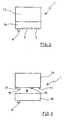
- FIG 2shows the ventilator according to Figure 1 in a highly schematic representation.
- the ventilatoris formed of a first device module (15) and a second device module (16).
- the second device module (16)is provided for receiving the control panel (2) and the display (3).
- FIG. 3illustrates that the second device module (16) from the first device module (15) is separable.
- the first device module (15) and the second device module (16)are interconnected via mechanical couplings (17), pneumatic couplings (18) and electrical couplings (19). In particular, it is thought to form the couplings (17, 18, 19) similar to male-female connections.
- FIG. 4shows the ventilator (1) after the positioning of a third device module (20) between the first device module (15) and the second device module (16).
- a respiratory gas humidifier (21) and a water chamber (22)are arranged in the area of the third device module (20).
- the water chamber (22)is preferably separable from the third device module (20) for ease of cleaning.
- the third device module (20)is provided with mechanical couplings (23), pneumatic couplings (24) and electrical couplings (25) in order to be able to connect both to the first device module (15) and to the second device module (16)
- the third device module (20)for this connection elements, which are formed to match the couplings (17, 18, 19).
- the third device module (20)can thereby be arranged between the first device module (15) and the second device module (16) and ensures a mechanical, pneumatic and electrical connection of the modules (15, 16, 20) with each other and with each other.
- FIG. 5shows the device modules (15, 16, 20) according to FIG. 4 in an interconnected state. It can be seen in particular that even with a combination of the device modules (15, 16, 20) together an extremely compact device construction is provided. In addition, there is no change in the area of the positioning of the display (3) and the functionality of the control panel (2).
Landscapes
- Health & Medical Sciences (AREA)
- Emergency Medicine (AREA)
- Pulmonology (AREA)
- Engineering & Computer Science (AREA)
- Anesthesiology (AREA)
- Biomedical Technology (AREA)
- Heart & Thoracic Surgery (AREA)
- Hematology (AREA)
- Life Sciences & Earth Sciences (AREA)
- Animal Behavior & Ethology (AREA)
- General Health & Medical Sciences (AREA)
- Public Health (AREA)
- Veterinary Medicine (AREA)
- Air Humidification (AREA)
- Glass Compositions (AREA)
- Separation Of Particles Using Liquids (AREA)
Abstract
Description
Translated fromGermanDie Erfindung betrifft eine Vorrichtung zur Beatmung, die eine Atemgasversorgung sowie einen Atemgasbefeuchter aufweist, der mit einem Flüssigkeitsreservoir sowie einer Heizung versehen ist, sowie bei der die Atemgasversorgung in einem ersten Gerätemodul angeordnet ist.The invention relates to a device for ventilation, which has a breathing gas supply and a respiratory gas humidifier, which is provided with a liquid reservoir and a heater, and in which the respiratory gas supply is arranged in a first device module.
Eine typische Verwendung derartiger Atemluftbefeuchter erfolgt im Zusammenhang mit Atemluftversorgungen, die im Rahmen einer CPAP-Therapie oder Bilevel-Therapie eingesetzt werden. Bei einer derartigen CPAP-Therapie (Continious-Positive-Airway-Pressure) wird einem Patienten im Zusammenhang mit der Therapie der Schlafapnoe wenigstens in Phasen eines Auftretens von Krankheitssymptomen Atemgas mit erhöhtem Druck zur Verfügung gestellt, um eine Abstützung des Atemweges zu erreichen.A typical use of such humidifiers is in connection with respiratory air supplies, which are used in the context of CPAP therapy or bilevel therapy. In such continuous-positive-airway-pressure (CPAP) therapy, respiratory gas at elevated pressure is provided to a patient in association with sleep apnea therapy, at least in phases of disease symptoms, to provide airway support.
Zur Vermeidung eines Austrocknens der Atemwege erweist es sich insbesondere bei längeren Beatmungsphasen als zweckmäßig, eine Befeuchtung der Atemluft durchzuführen. Derartige Befeuchtungen der Atemluft können auch bei anderen Anwendungen realisiert werden.To avoid dehydration of the respiratory tract, it proves to be particularly useful for longer periods of ventilation to carry out a humidification of the air. Such humidification of the breathing air can also be realized in other applications.
Typischerweise erfolgt eine Beheizung eines als Flüssigkeitsreservoir verwendeten Wassertanks des Befeuchtungssystems indirekt über einen unteren metallischen Boden des Wassertanks. Der metallische Boden wird ähnlich wie bei einem Herd auf eine Heizplatte aufgesetzt und im Bereich der Heizplatte sind elektrische Heizelemente angeordnet. Aufgrund der einzuhaltenden hygienischen Anforderungen muß der Boden zum Reinigen abnehmbar sein und trotzdem eine ausreichende Abdichtung gegen das zu erwärmende Wasser gewährleisten. Eine direkte Beheizung ist mittels eines Heizstabes direkt im Wasser möglich.Typically, a heating of a water tank of the humidification system used as a liquid reservoir takes place indirectly via a lower metallic bottom of the water tank. The metallic bottom is placed similarly to a stove on a hot plate and in the heating plate electrical heating elements are arranged. Due to the hygienic requirements to be met, the floor must be removable for cleaning and still ensure adequate sealing against the water to be heated. Direct heating is possible by means of a heating rod directly in the water.
Ebenfalls ist es bereits bekannt, an ein Beatmungsgerät extern außenseitig einen Atemgasbefeuchter anzuschließen. Da die Atemgasbefeuchter in der Regel mit einer elektrischen Heizung ausgestattet sind, ist es bei derartigen Ausführungsformen aber erforderlich, außenseitig am Beatmungsgerät elektrische Anschlüsse vorzusehen. Eine derartige Ausführungsform wird beispielsweise in der PCT-WO 01/10489 beschrieben. Innerhalb eines Beatmungsgerätes angeordnete Atemgasbefeuchter werden beispielsweise in der PCT-WO 98/04311 beschrieben. Eine derartige Anordnung führt jedoch bei einem Betrieb des Beatmungsgerätes ohne Befeuchtung zu einem unnötig großen Gerätevolumen, wodurch der Benutzungskomfort reduziert wird.It is also already known to connect to a respirator externally on the outside a Atemgasbefeuchter. Since the humidifiers are usually equipped with an electric heater, it is necessary in such embodiments, however, to provide electrical connections on the outside of the ventilator. Such an embodiment is described for example in PCT-WO 01/10489. Within a ventilator arranged breathing gas humidifiers are described for example in PCT WO 98/04311. However, such an arrangement results in an operation of the ventilator without humidification to an unnecessarily large volume of equipment, whereby the ease of use is reduced.
Die bekannten Beatmungsgeräte werden sowohl mit fest integrierten Anfeuchtern als auch mit bei Bedarf aktivierbaren Anfeuchtungsmodulen verwendet. Bei fest eingebauten Anfeuchtern besteht der Nachteil, daß diese auch bei einer Nichtbenutzung der Anfeuchtung gereinigt werden müssen. Die Beatmungsgeräte sind darüber hinaus unnötig groß sowie schwer und der Aufwand für die Pflege und die Reinigung wird bei unbenutztem Anfeuchter unnötig hoch. Darüber hinaus wird auch die Handhabung für einen Patienten, der keine Anfeuchtung des Atemgases benötigt, unnötig kompliziert.The known ventilators are both with permanently integrated humidifiers as well as activated if necessary Humidification modules used. With fixed humidifiers there is the disadvantage that they must be cleaned even when not using the moistening. In addition, the ventilators are unnecessarily large and heavy and the cost of care and cleaning unnecessarily high in unused humidifier. In addition, the handling for a patient who does not need humidification of the breathing gas, unnecessarily complicated.
Bei außenseitig am Beatmungsgerät angebrachten Befeuchtungsmodulen besteht häufig das 'Problem einer ungenügenden Standfestigkeit, da bei einer häufigen Benutzung durch den Patienten selbst hohe Beanspruchungen im Hinblick auf die mechanische Festigkeit erfolgen. Darüber hinaus sind häufig elektrische Kontakte für die Übergabe der benötigten elektrischen Leistung ohne angekoppelten Anfeuchter ungeschützt und können verschmutzen.When moistening modules are mounted on the outside of the ventilator, there is often the problem of inadequate stability, since frequent use by the patient places high demands on mechanical strength. In addition, often electrical contacts for the transfer of the required electrical power without coupled humidifier unprotected and can pollute.
Eine Vorrichtung zur Beatmung gemäss der Oberbegriff vom Anspruch 1 ist aus dem Dokument WO-A-01/10489 A bekannt.A ventilation device according to the preamble of
Aufgabe der vorliegenden Erfindung ist es, eine Vorrichtung der einleitend genannten Art derart zu konstruieren, daß sowohl bei einer Verwendung mit aktiviertem Anfeuchter als auch ohne Anfeuchter ein verbesserter Benutzungskomfort sowie eine verbesserte Benutzungssicherheit bereitgestellt werden.The object of the present invention is to construct a device of the type mentioned in the introduction in such a way that both when used with an activated humidifier and without a humidifier an improved ease of use and an improved safety of use are provided.
Diese Aufgabe wird erfindungsgemäß dadurch gelöst, daß das erste Gerätemodul lösbar mit einem zweiten Gerätemodul verbunden ist, daß der Atemgasbefeuchter in einem dritten Gerätemodul angeordnet ist und daß das dritte Gerätemodul mindestens bereichsweise zwischen dem ersten Gerätemodul und dem zweiten Gerätemodul anordbar ist.This object is achieved in that the first device module is detachably connected to a second device module that the Atemgasbefeuchter is arranged in a third device module and that the third device module at least partially between the first device module and the second device module can be arranged.
Die modulare Ausbildung der Gerätekomponenten ermöglicht es, jeweils nur die Gerätekomponenten zu verwenden, die auch tatsächlich benötigt werden. Durch die Anordbarkeit des dritten Gerätemoduls mit dem Befeuchter zwischen dem ersten Gerätemodul und dem zweiten Gerätemodul ist es möglich, die jeweils benötigten elektrischen und pneumatischen Kupplungselemente in jedem Betriebszustand gegenüber von Verschmutzungen und mechanischen Beschädigungen geschützt anzuordnen. Darüber hinaus wird einem Benutzer in jedem Betriebszustand des Gerätes ein im wesentlichen gleiches äußeres Erscheinungsbild vermittelt und es erfolgt keine wesentliche Veränderung einer Anordnung oder Funktionalität von Bedienungselementen.The modular design of the device components makes it possible to use only the device components that actually needed. By arranging the third device module with the humidifier between the first device module and the second device module, it is possible to arrange the respective required electrical and pneumatic coupling elements protected in each operating state against dirt and mechanical damage. In addition, a user is given in each operating state of the device, a substantially same appearance and there is no significant change in an arrangement or functionality of controls.
Zur Bereitstellung einer von einer jeweiligen Gerätekonfiguration unabhängigen Bedienoberfläche wird vorgeschlagen, daß im Bereich des zweiten Gerätemoduls ein Bedienfeld angeordnet ist.In order to provide a user interface independent of a respective device configuration, it is proposed that a control panel be arranged in the region of the second device module.
Insbesondere ist daran gedacht, daß das Bedienfeld elektrische Bedienelemente aufweist.In particular, it is contemplated that the control panel has electrical controls.
Darüber hinaus ist auch vorgesehen, daß das Bedienfeld pneumatische Bedienelemente aufweist.In addition, it is also envisaged that the control panel has pneumatic controls.
Eine von der jeweiligen Gerätekonfiguration unabhängige Schnittstelle zum Anschluß eines Beatmungsschlauches kann dadurch erfolgen, daß das zweite Gerätemodul ein Anschlußelement für einen verbindungsschlauch aufweist.An independent of the respective device configuration interface for connecting a breathing tube can be effected in that the second device module has a connection element for a connecting hose.
Eine mechanisch sehr stabile Konstruktion wird dadurch bereitgestellt, daß das zweite Gerätemodul eine schubladenförmige Halterung zur mindestens teilweisen Aufnahme des dritten Gerätemoduls aufweist.A mechanically very stable construction is provided in that the second device module has a drawer-shaped holder for at least partially receiving the third device module.
Zur Erleichterung einer Gerätereinigung wird vorgeschlagen, daß das dritte Gerätemodul eine abnehmbare Wasserkammer aufweist.To facilitate a device cleaning is proposed that the third device module has a removable water chamber.
Ein einfaches Trennen und Zusammensetzen der Gerätemodule wird dadurch unterstützt, daß das zweite Gerätemodul aus dem ersten Gerätemodul herausziehbar ausgebildet ist.Simple separation and assembly of the device modules is supported by the fact that the second device module is designed to be pulled out of the first device module.
Eine weitere Konstruktionsvariante besteht darin, daß das zweite Gerätemodul aus dem ersten Gerätemodul herausnehmbar ausgebildet ist.Another design variant is that the second device module is designed removable from the first device module.
Ein typisches Anwendungsgebiet wird dadurch definiert, daß die Gerätemodule zur verwendung für ein CPAP- oder Bilevel-Beatmungsgerät ausgebildet sind.A typical field of application is defined by the fact that the device modules are adapted for use with a CPAP or bilevel ventilator.
Ein weiteres Anwendungsfeld besteht darin, daß die Gerätemodule zur verwendung bei einem Beatmungsgerät für invasive Anwendungen ausgebildet sind.Another field of application is that the device modules are designed for use in a ventilator for invasive applications.
In den Zeichnungen sind Ausführungsbeispiele der Erfindung schematisch dargestellt. Es zeigen:
- Fig. 1
- Eine perspektivische Darstellung eines Beatmungsgerätes ohne angekoppelten Vorratsbehälter für Befeuchtungsflüssigkeit,
- Fig. 2
- eine schematisierte Darstellung des Gerätes nach
Figur 1 mit Aufteilung in ein erstes Gerätemodul und ein zweites Gerätemodul, - Fig. 3
- die Vorrichtung gemäß
Figur 2 nach einer Trennung der beiden Gerätemodule, - Fig. 4
- die vorrichtung gemäß Fig. 3 nach einem Positionieren eines dritten Gerätemoduls, das den Anfeuchter beinhaltet und
- Fig. 5
- die Vorrichtung der es Figur 4 nach einem Zusammenfügen der drei Gerätemodule.
- Fig. 1
- A perspective view of a ventilator without a coupled reservoir for moistening liquid,
- Fig. 2
- 1 is a schematic illustration of the device according to FIG. 1 with a division into a first device module and a second device module, FIG.
- Fig. 3
- the device according to FIG. 2 after a separation of the two device modules,
- Fig. 4
- the device of FIG. 3 after positioning a third device module, which includes the humidifier and
- Fig. 5
- the device of Figure 4 after joining the three device modules.
Fig. 1 zeigt den grundsätzlichen Aufbau einer Vorrichtung zur Beatmung. Im Bereich eines Beatmungsgerätes (1) mit Bedienfeld (2) sowie Anzeige (3) ist in einem Geräteinnenraum eine Atemgaspumpe angeordnet. Über eine Kopplung (4) wird ein Verbindungsschlauch (5) angeschlossen. Die Kopplung (4) greift in einen Anschlußstutzen (6) des Beatmungsgerätes (1) ein. Entlang des Verbindungsschlauches (5) kann ein zusätzlicher Druckmeßschlauch (7) verlaufen, der über einen Druckeingangsstutzen (8) mit dem Beatmungsgerät (1) verbindbar ist. Zur Ermöglichung einer Datenübertragung weist das Beatmungsgerät (1) eine Schnittstelle (9) auf.Fig. 1 shows the basic structure of a device for ventilation. In the area of a ventilator (1) with control panel (2) and display (3), a breathing gas pump is arranged in a device interior. A coupling hose (5) is connected via a coupling (4). The coupling (4) engages in a connecting piece (6) of the ventilator (1). Along the connecting tube (5), an additional Druckmeßschlauch (7) extend, which is connectable via a pressure input port (8) with the ventilator (1). To enable data transmission, the ventilator (1) has an interface (9).
Im Bereich einer dem Beatmungsgerät (1) abgewandten Ausdehnung des verbindungsschlauches (5) ist ein Ausatmungselement (14) angeordnet.An exhalation element (14) is arranged in the region of an extension of the connecting tube (5) facing away from the ventilator (1).
Fig. 1 zeigt darüber hinaus eine Beatmungsmaske (11), die als Nasalmaske ausgebildet ist. Eine Fixierung im Bereich eines Kopfes eines Patienten kann über eine Kopfhaube (12) erfolgen. Im Bereich ihrer dem Verbindungsschlauch (5) zugewandten Ausdehnung weist die. Beatmungsmaske (11) ein Kupplungselement (13) auf.Fig. 1 also shows a respiratory mask (11), which is designed as a nasal mask. A fixation in the region of a head of a patient can be done via a hood (12). In the region of the connection hose (5) facing extension, the. Respiratory mask (11) a coupling element (13).
Figur 2 zeigt das Beatmungsgerät entsprechend Figur 1 in einer stark schematisierten Darstellung. Insbesondere ist zu erkennen, daß das Beatmungsgerät aus einem ersten Gerätemodul (15) sowie einem zweiten Gerätemodul (16) ausgebildet ist. Im Bereich des ersten Gerätemoduls (15) ist eine Atemgasversorgung angeordnet. Das zweite Gerätemodul (16) ist zur Aufnahme des Bedienfeldes (2) sowie der Anzeige (3) vorgesehen.Figure 2 shows the ventilator according to Figure 1 in a highly schematic representation. In particular, it can be seen that the ventilator is formed of a first device module (15) and a second device module (16). In the area of the first device module (15) is a Breathing gas supply arranged. The second device module (16) is provided for receiving the control panel (2) and the display (3).
Die Darstellung in Figur 3 veranschaulicht, daß das zweite Gerätemodul (16) vom ersten Gerätemodul (15) trennbar ist. Das erste Gerätemodul (15) und das zweite Gerätemodul (16) sind über mechanische Kopplungen (17), pneumatische Kopplungen (18) sowie elektrische Kopplungen (19) miteinander verbunden. Insbesondere ist daran gedacht, die Kopplungen (17, 18, 19) ähnlich zu Stecker-Buchsen-Verbindungen auszubilden.The illustration in Figure 3 illustrates that the second device module (16) from the first device module (15) is separable. The first device module (15) and the second device module (16) are interconnected via mechanical couplings (17), pneumatic couplings (18) and electrical couplings (19). In particular, it is thought to form the couplings (17, 18, 19) similar to male-female connections.
Figur 4 zeigt das Beatmungsgerät (1) nach der Positionierung eines dritten Gerätemoduls (20) zwischen dem ersten Gerätemodul (15) und dem zweiten Gerätemodul (16). Im Bereich des dritten Gerätemoduls (20) sind ein Atemgasbefeuchter (21) sowie eine Wasserkammer (22) angeordnet. Die Wasserkammer (22) ist zur Erleichterung einer Reinigungsfähigkeit vorzugsweise vom dritten Gerätemodul (20) trennbar ausgebildet.FIG. 4 shows the ventilator (1) after the positioning of a third device module (20) between the first device module (15) and the second device module (16). In the area of the third device module (20) a respiratory gas humidifier (21) and a water chamber (22) are arranged. The water chamber (22) is preferably separable from the third device module (20) for ease of cleaning.
Das dritte Gerätemodul (20) ist mit mechanischen Kopplungen (23), pneumatischen Kopplungen (24) sowie elektrischen Kopplungen (25) versehen, um eine verbindung sowohl mit dem ersten Gerätemodul (15) als auch mit dem zweiten Gerätemodul (16) durchführen zu können.. Insbesondere weist das dritte Gerätemodul (20) hierfür Verbindungselemente auf, die zu den Kopplungen (17, 18, 19) passend ausgebildet sind. Das dritte Gerätemodul (20) ist hierdurch zwischen dem ersten Gerätemodul (15) und dem zweiten Gerätemodul (16) anordbar und gewährleistet eine mechanische, pneumatische und elektrische Verbindung der Module (15, 16, 20) miteinander und untereinander.The third device module (20) is provided with mechanical couplings (23), pneumatic couplings (24) and electrical couplings (25) in order to be able to connect both to the first device module (15) and to the second device module (16) In particular, the third device module (20) for this connection elements, which are formed to match the couplings (17, 18, 19). The third device module (20) can thereby be arranged between the first device module (15) and the second device module (16) and ensures a mechanical, pneumatic and electrical connection of the modules (15, 16, 20) with each other and with each other.
Figur 5 zeigt die Gerätemodule (15, 16, 20) nach Figur 4 in einem miteinander verbundenen Zustand. Es ist insbesondere erkennbar, daß auch bei einer Kombination der Gerätemodule (15, 16, 20) miteinander eine äußerst kompakte Gerätekonstruktion bereitgestellt wird. Es erfolgt darüber hinaus keine Änderung im Bereich der Positionierung der Anzeige (3) sowie der Funktionalität des Bedienfeldes (2).FIG. 5 shows the device modules (15, 16, 20) according to FIG. 4 in an interconnected state. It can be seen in particular that even with a combination of the device modules (15, 16, 20) together an extremely compact device construction is provided. In addition, there is no change in the area of the positioning of the display (3) and the functionality of the control panel (2).
Claims (11)
- Respiratory device with a respiratory gas supply and a respiratory gas humidifier, which is provided with a liquid reservoir and a heating system, the respiratory gas supply being disposed in a first device module,characterised in that the first device module (15) is releasably connected to a second device module (16), the respiratory gas humidifier (21) is disposed in a third device module (20) and at least certain regions of the third device module (20) can be disposed between the first device module (15) and the second device module (16).
- Device as claimed in claim 1,characterised in that a control panel (2) is disposed in the region of the second device module (15).
- Device as claimed in claim 1 and 2,characterised in that the control panel (2) has electric control elements.
- Device as claimed in claim 1 and 2,characterised in that the control panel (2) has pneumatic control elements.
- Device as claimed in one of claims 1 to 4,characterised in that the second device module (16) has a connector element for a connecting flexible pipe (5).
- Device as claimed in one of clams 1 to 5,characterised in that the second device module (16) has a drawer-shaped retaining means for at least partially accommodating the third device module (20).
- Device as claimed in one of claims 1 to 6,characterised in that the third device module (20) has a removable water chamber (22).
- Device as claimed in one of claims 1 to 7,characterised in that the second device module (16) can be pulled out of the first device module (15).
- Device as claimed in one of claims 1 to 7,characterised in that the second device module (16) is designed so that it can be removed from the first device module (15).
- Device as claimed in one of claims 1 to 9,characterised in that the device modules (15, 16, 20) are designed for use with a CPAP or bi-level respiratory device.
- Device as claimed in one of claims 1 to 9,characterised in that the device modules (15, 16, 20) are designed for use with a respiratory device for invasive applications.
Applications Claiming Priority (2)
| Application Number | Priority Date | Filing Date | Title |
|---|---|---|---|
| DE10310462.3ADE10310462B4 (en) | 2003-03-11 | 2003-03-11 | Apparatus for ventilation |
| DE10310462 | 2003-03-11 |
Publications (2)
| Publication Number | Publication Date |
|---|---|
| EP1457223A1 EP1457223A1 (en) | 2004-09-15 |
| EP1457223B1true EP1457223B1 (en) | 2006-10-11 |
Family
ID=32748184
Family Applications (1)
| Application Number | Title | Priority Date | Filing Date |
|---|---|---|---|
| EP03028063AExpired - LifetimeEP1457223B1 (en) | 2003-03-11 | 2003-12-09 | Breathing device |
Country Status (3)
| Country | Link |
|---|---|
| EP (1) | EP1457223B1 (en) |
| AT (1) | ATE342086T1 (en) |
| DE (2) | DE10310462B4 (en) |
Cited By (6)
| Publication number | Priority date | Publication date | Assignee | Title |
|---|---|---|---|---|
| WO2015038013A1 (en)* | 2013-09-13 | 2015-03-19 | Fisher And Paykel Healthcare Limited | Connections for humidifcation system |
| US10974015B2 (en) | 2012-03-15 | 2021-04-13 | Fisher & Paykel Healthcare Limited | Respiratory gas humidification system |
| US11129956B2 (en) | 2012-04-27 | 2021-09-28 | Fisher & Paykel Healthcare Limited | Usability features for respiratory humidification system |
| US11324911B2 (en) | 2014-06-03 | 2022-05-10 | Fisher & Paykel Healthcare Limited | Flow mixers for respiratory therapy systems |
| US11351332B2 (en) | 2016-12-07 | 2022-06-07 | Fisher & Paykel Healthcare Limited | Sensing arrangements for medical devices |
| US11559653B2 (en) | 2014-02-07 | 2023-01-24 | Fisher & Paykel Healthcare Limited | Respiratory humidification system |
Families Citing this family (8)
| Publication number | Priority date | Publication date | Assignee | Title |
|---|---|---|---|---|
| US7677246B2 (en)* | 2005-09-23 | 2010-03-16 | Ric Investments, Llc | Modular pressure support system |
| DK3685877T3 (en) | 2011-06-03 | 2023-10-02 | Fisher & Paykel Healthcare Ltd | MEDICAL TUBES CONSISTING OF CONDUCTIVE FILAMENTS AND METHODS OF PRODUCTION |
| GB2527210B (en) | 2012-12-04 | 2020-02-05 | Fisher & Paykel Healthcare Ltd | A Breathing Tube and Method of Manufacturing a Breathing Tube |
| US10814091B2 (en) | 2013-10-24 | 2020-10-27 | Fisher & Paykel Healthcare Limited | System for delivery of respiratory gases |
| CN106029147B (en) | 2013-12-20 | 2020-01-21 | 费雪派克医疗保健有限公司 | Humidification system connection |
| CN111265754B (en) | 2014-03-17 | 2023-06-06 | 费雪派克医疗保健有限公司 | Medical tube for respiratory system |
| NZ737589A (en) | 2015-06-24 | 2023-03-31 | Fisher & Paykel Healthcare Ltd | Breathing assistance apparatus |
| WO2017043981A1 (en) | 2015-09-09 | 2017-03-16 | Po-Yen Liu | Zone heating for respiratory circuits |
Family Cites Families (8)
| Publication number | Priority date | Publication date | Assignee | Title |
|---|---|---|---|---|
| CH576791A5 (en)* | 1974-03-28 | 1976-06-30 | Hoffmann La Roche | |
| US4016878A (en)* | 1975-06-27 | 1977-04-12 | Foundation For Ocean Research | Heater and humidifier for breathing apparatus |
| ZA835856B (en)* | 1982-08-23 | 1985-03-27 | Kendall & Co | Pediatric cartridge humidifier |
| GB2173107B (en)* | 1985-04-04 | 1988-06-15 | Boc Group Plc | Improvements in inhalation apparatus |
| SE503089C2 (en)* | 1991-09-20 | 1996-03-25 | Gibeck Respiration Ab | Apparatus for connecting a patient to a respirator comprising a humidifier heat exchanger and use of a humidifier for heat exchanger in this apparatus |
| GB2284356B (en)* | 1993-11-22 | 1997-10-29 | Fisher & Paykel | Respiratory humidifier conduit |
| DE19630466C2 (en)* | 1996-07-27 | 1998-05-07 | Nikolaus Netzer | Device for supplying gas for sleep apnea |
| EP2308539B1 (en)* | 1999-08-05 | 2016-04-20 | ResMed R&D Germany GmbH | Device for supplying respiratory gas, humidifying device, respiratory gas tube, and connecting device therefor |
- 2003
- 2003-03-11DEDE10310462.3Apatent/DE10310462B4/ennot_activeExpired - Lifetime
- 2003-12-09EPEP03028063Apatent/EP1457223B1/ennot_activeExpired - Lifetime
- 2003-12-09ATAT03028063Tpatent/ATE342086T1/ennot_activeIP Right Cessation
- 2003-12-09DEDE50305345Tpatent/DE50305345D1/ennot_activeExpired - Lifetime
Cited By (11)
| Publication number | Priority date | Publication date | Assignee | Title |
|---|---|---|---|---|
| US10974015B2 (en) | 2012-03-15 | 2021-04-13 | Fisher & Paykel Healthcare Limited | Respiratory gas humidification system |
| US12350436B2 (en) | 2012-03-15 | 2025-07-08 | Fisher & Paykel Healthcare Limited | Respiratory gas humidification system |
| US11129956B2 (en) | 2012-04-27 | 2021-09-28 | Fisher & Paykel Healthcare Limited | Usability features for respiratory humidification system |
| WO2015038013A1 (en)* | 2013-09-13 | 2015-03-19 | Fisher And Paykel Healthcare Limited | Connections for humidifcation system |
| GB2534496A (en)* | 2013-09-13 | 2016-07-27 | Fisher & Paykel Healthcare Ltd | Connections for humidification system |
| US10245407B2 (en) | 2013-09-13 | 2019-04-02 | Fisher & Paykel Healthcare Limited | Connections for humidification system |
| GB2534496B (en)* | 2013-09-13 | 2020-04-01 | Fisher & Paykel Healthcare Ltd | A cartridge for a respiratory humidifier |
| US11801360B2 (en) | 2013-09-13 | 2023-10-31 | Fisher & Paykel Healthcare Limited | Connections for humidification system |
| US11559653B2 (en) | 2014-02-07 | 2023-01-24 | Fisher & Paykel Healthcare Limited | Respiratory humidification system |
| US11324911B2 (en) | 2014-06-03 | 2022-05-10 | Fisher & Paykel Healthcare Limited | Flow mixers for respiratory therapy systems |
| US11351332B2 (en) | 2016-12-07 | 2022-06-07 | Fisher & Paykel Healthcare Limited | Sensing arrangements for medical devices |
Also Published As
| Publication number | Publication date |
|---|---|
| DE50305345D1 (en) | 2006-11-23 |
| ATE342086T1 (en) | 2006-11-15 |
| DE10310462B4 (en) | 2017-01-05 |
| DE10310462A1 (en) | 2004-09-23 |
| EP1457223A1 (en) | 2004-09-15 |
Similar Documents
| Publication | Publication Date | Title |
|---|---|---|
| EP1457223B1 (en) | Breathing device | |
| DE4441380B4 (en) | Line for heated, humidified breathing air | |
| DE60224947T2 (en) | MEDICAL CONNECTING PIECE FOR A VENTILATION ASSEMBLY | |
| EP2819732B1 (en) | Respiratory tube | |
| EP2703034B1 (en) | Device for the humidification of respiratory gas | |
| DE102011054131A1 (en) | Breathing circuit | |
| DE202006007397U1 (en) | Ventilation hose with different heating zones | |
| DE19903732A1 (en) | Ventilation device and method for processing a respiratory gas | |
| EP1197237B1 (en) | Breathing device | |
| DE102012009639A1 (en) | Ceiling Supply Unit | |
| EP1479404B1 (en) | Method for supplying breathable gas and breathing device | |
| EP1277488B1 (en) | Filtering device for respiratory air | |
| DE102023100948A1 (en) | Clamp, particularly for a connection between a ventilator and a patient | |
| DE102012223445A1 (en) | Medical tube unit and device for administering a breathing gas | |
| EP0806217A2 (en) | Heated respiratory hose and method of producing the same | |
| DE102012002632B4 (en) | Ventilation system and connector system for this to reduce contamination | |
| EP3858413A1 (en) | Curved connecting unit for connecting a patient side coupling unit to a medical apparatus | |
| DE102011014018B4 (en) | Apparatus for filtering respiratory gas | |
| EP2452717B1 (en) | Heated breathing tube system | |
| DE202004020412U1 (en) | Ventilation system and heated tube arrangement with temperature sensor for a respiratory system | |
| EP3852853B1 (en) | System for assisting breathing | |
| WO2021027983A1 (en) | Coupling part for ventilator circuit | |
| DE102015119523A1 (en) | Breathing circuit | |
| DE102005012753A1 (en) | Breathing apparatus for patients has control unit for compressed gas source and sequence valve for enriching breathing gas with oxygen that is connected to control unit | |
| DE20023472U1 (en) | Respiration apparatus has heating element in region of water tank for humidifying air supplied for breathing |
Legal Events
| Date | Code | Title | Description |
|---|---|---|---|
| PUAI | Public reference made under article 153(3) epc to a published international application that has entered the european phase | Free format text:ORIGINAL CODE: 0009012 | |
| 17P | Request for examination filed | Effective date:20040330 | |
| AK | Designated contracting states | Kind code of ref document:A1 Designated state(s):AT BE BG CH CY CZ DE DK EE ES FI FR GB GR HU IE IT LI LU MC NL PT RO SE SI SK TR | |
| AX | Request for extension of the european patent | Extension state:AL LT LV MK | |
| AKX | Designation fees paid | Designated state(s):AT BE BG CH CY CZ DE DK EE ES FI FR GB GR HU IE IT LI LU MC NL PT RO SE SI SK TR | |
| GRAP | Despatch of communication of intention to grant a patent | Free format text:ORIGINAL CODE: EPIDOSNIGR1 | |
| GRAS | Grant fee paid | Free format text:ORIGINAL CODE: EPIDOSNIGR3 | |
| GRAA | (expected) grant | Free format text:ORIGINAL CODE: 0009210 | |
| AK | Designated contracting states | Kind code of ref document:B1 Designated state(s):AT BE BG CH CY CZ DE DK EE ES FI FR GB GR HU IE IT LI LU MC NL PT RO SE SI SK TR | |
| PG25 | Lapsed in a contracting state [announced via postgrant information from national office to epo] | Ref country code:CZ Free format text:LAPSE BECAUSE OF FAILURE TO SUBMIT A TRANSLATION OF THE DESCRIPTION OR TO PAY THE FEE WITHIN THE PRESCRIBED TIME-LIMIT Effective date:20061011 Ref country code:IE Free format text:LAPSE BECAUSE OF FAILURE TO SUBMIT A TRANSLATION OF THE DESCRIPTION OR TO PAY THE FEE WITHIN THE PRESCRIBED TIME-LIMIT Effective date:20061011 Ref country code:SK Free format text:LAPSE BECAUSE OF FAILURE TO SUBMIT A TRANSLATION OF THE DESCRIPTION OR TO PAY THE FEE WITHIN THE PRESCRIBED TIME-LIMIT Effective date:20061011 Ref country code:NL Free format text:LAPSE BECAUSE OF FAILURE TO SUBMIT A TRANSLATION OF THE DESCRIPTION OR TO PAY THE FEE WITHIN THE PRESCRIBED TIME-LIMIT Effective date:20061011 Ref country code:FI Free format text:LAPSE BECAUSE OF FAILURE TO SUBMIT A TRANSLATION OF THE DESCRIPTION OR TO PAY THE FEE WITHIN THE PRESCRIBED TIME-LIMIT Effective date:20061011 Ref country code:SI Free format text:LAPSE BECAUSE OF FAILURE TO SUBMIT A TRANSLATION OF THE DESCRIPTION OR TO PAY THE FEE WITHIN THE PRESCRIBED TIME-LIMIT Effective date:20061011 Ref country code:RO Free format text:LAPSE BECAUSE OF FAILURE TO SUBMIT A TRANSLATION OF THE DESCRIPTION OR TO PAY THE FEE WITHIN THE PRESCRIBED TIME-LIMIT Effective date:20061011 | |
| REG | Reference to a national code | Ref country code:GB Ref legal event code:FG4D Free format text:NOT ENGLISH | |
| REG | Reference to a national code | Ref country code:CH Ref legal event code:EP | |
| REG | Reference to a national code | Ref country code:IE Ref legal event code:FG4D Free format text:LANGUAGE OF EP DOCUMENT: GERMAN | |
| REF | Corresponds to: | Ref document number:50305345 Country of ref document:DE Date of ref document:20061123 Kind code of ref document:P | |
| PG25 | Lapsed in a contracting state [announced via postgrant information from national office to epo] | Ref country code:BE Free format text:LAPSE BECAUSE OF NON-PAYMENT OF DUE FEES Effective date:20061231 Ref country code:MC Free format text:LAPSE BECAUSE OF NON-PAYMENT OF DUE FEES Effective date:20061231 | |
| PG25 | Lapsed in a contracting state [announced via postgrant information from national office to epo] | Ref country code:SE Free format text:LAPSE BECAUSE OF FAILURE TO SUBMIT A TRANSLATION OF THE DESCRIPTION OR TO PAY THE FEE WITHIN THE PRESCRIBED TIME-LIMIT Effective date:20070111 Ref country code:BG Free format text:LAPSE BECAUSE OF FAILURE TO SUBMIT A TRANSLATION OF THE DESCRIPTION OR TO PAY THE FEE WITHIN THE PRESCRIBED TIME-LIMIT Effective date:20070111 Ref country code:DK Free format text:LAPSE BECAUSE OF FAILURE TO SUBMIT A TRANSLATION OF THE DESCRIPTION OR TO PAY THE FEE WITHIN THE PRESCRIBED TIME-LIMIT Effective date:20070111 | |
| PG25 | Lapsed in a contracting state [announced via postgrant information from national office to epo] | Ref country code:ES Free format text:LAPSE BECAUSE OF FAILURE TO SUBMIT A TRANSLATION OF THE DESCRIPTION OR TO PAY THE FEE WITHIN THE PRESCRIBED TIME-LIMIT Effective date:20070122 | |
| PG25 | Lapsed in a contracting state [announced via postgrant information from national office to epo] | Ref country code:PT Free format text:LAPSE BECAUSE OF FAILURE TO SUBMIT A TRANSLATION OF THE DESCRIPTION OR TO PAY THE FEE WITHIN THE PRESCRIBED TIME-LIMIT Effective date:20070319 | |
| NLV1 | Nl: lapsed or annulled due to failure to fulfill the requirements of art. 29p and 29m of the patents act | ||
| GBV | Gb: ep patent (uk) treated as always having been void in accordance with gb section 77(7)/1977 [no translation filed] | Effective date:20061011 | |
| REG | Reference to a national code | Ref country code:IE Ref legal event code:FD4D | |
| EN | Fr: translation not filed | ||
| PLBE | No opposition filed within time limit | Free format text:ORIGINAL CODE: 0009261 | |
| STAA | Information on the status of an ep patent application or granted ep patent | Free format text:STATUS: NO OPPOSITION FILED WITHIN TIME LIMIT | |
| 26N | No opposition filed | Effective date:20070712 | |
| PG25 | Lapsed in a contracting state [announced via postgrant information from national office to epo] | Ref country code:GB Free format text:LAPSE BECAUSE OF FAILURE TO SUBMIT A TRANSLATION OF THE DESCRIPTION OR TO PAY THE FEE WITHIN THE PRESCRIBED TIME-LIMIT Effective date:20061011 | |
| BERE | Be: lapsed | Owner name:WEINMANN GERATE FUR MEDIZIN G.M.B.H. & CO. KG Effective date:20061231 | |
| PG25 | Lapsed in a contracting state [announced via postgrant information from national office to epo] | Ref country code:AT Free format text:LAPSE BECAUSE OF NON-PAYMENT OF DUE FEES Effective date:20061209 | |
| PG25 | Lapsed in a contracting state [announced via postgrant information from national office to epo] | Ref country code:GR Free format text:LAPSE BECAUSE OF FAILURE TO SUBMIT A TRANSLATION OF THE DESCRIPTION OR TO PAY THE FEE WITHIN THE PRESCRIBED TIME-LIMIT Effective date:20070112 Ref country code:FR Free format text:LAPSE BECAUSE OF FAILURE TO SUBMIT A TRANSLATION OF THE DESCRIPTION OR TO PAY THE FEE WITHIN THE PRESCRIBED TIME-LIMIT Effective date:20070601 | |
| PG25 | Lapsed in a contracting state [announced via postgrant information from national office to epo] | Ref country code:EE Free format text:LAPSE BECAUSE OF FAILURE TO SUBMIT A TRANSLATION OF THE DESCRIPTION OR TO PAY THE FEE WITHIN THE PRESCRIBED TIME-LIMIT Effective date:20061011 | |
| PG25 | Lapsed in a contracting state [announced via postgrant information from national office to epo] | Ref country code:TR Free format text:LAPSE BECAUSE OF FAILURE TO SUBMIT A TRANSLATION OF THE DESCRIPTION OR TO PAY THE FEE WITHIN THE PRESCRIBED TIME-LIMIT Effective date:20061011 Ref country code:HU Free format text:LAPSE BECAUSE OF FAILURE TO SUBMIT A TRANSLATION OF THE DESCRIPTION OR TO PAY THE FEE WITHIN THE PRESCRIBED TIME-LIMIT Effective date:20070412 Ref country code:LU Free format text:LAPSE BECAUSE OF NON-PAYMENT OF DUE FEES Effective date:20061209 | |
| REG | Reference to a national code | Ref country code:CH Ref legal event code:PL | |
| PG25 | Lapsed in a contracting state [announced via postgrant information from national office to epo] | Ref country code:LI Free format text:LAPSE BECAUSE OF NON-PAYMENT OF DUE FEES Effective date:20071231 Ref country code:CH Free format text:LAPSE BECAUSE OF NON-PAYMENT OF DUE FEES Effective date:20071231 | |
| PG25 | Lapsed in a contracting state [announced via postgrant information from national office to epo] | Ref country code:CY Free format text:LAPSE BECAUSE OF FAILURE TO SUBMIT A TRANSLATION OF THE DESCRIPTION OR TO PAY THE FEE WITHIN THE PRESCRIBED TIME-LIMIT Effective date:20061011 Ref country code:FR Free format text:LAPSE BECAUSE OF FAILURE TO SUBMIT A TRANSLATION OF THE DESCRIPTION OR TO PAY THE FEE WITHIN THE PRESCRIBED TIME-LIMIT Effective date:20061011 | |
| PGFP | Annual fee paid to national office [announced via postgrant information from national office to epo] | Ref country code:IT Payment date:20101228 Year of fee payment:8 | |
| PG25 | Lapsed in a contracting state [announced via postgrant information from national office to epo] | Ref country code:IT Free format text:LAPSE BECAUSE OF NON-PAYMENT OF DUE FEES Effective date:20121209 | |
| REG | Reference to a national code | Ref country code:DE Ref legal event code:R082 Ref document number:50305345 Country of ref document:DE Representative=s name:MARX, THOMAS, DR., DE Ref country code:DE Ref legal event code:R081 Ref document number:50305345 Country of ref document:DE Owner name:LOEWENSTEIN MEDICAL TECHNOLOGY S.A., LU Free format text:FORMER OWNER: WEINMANN GERAETE FUER MEDIZIN GMBH & CO. KG, 22525 HAMBURG, DE | |
| PGFP | Annual fee paid to national office [announced via postgrant information from national office to epo] | Ref country code:DE Payment date:20221221 Year of fee payment:20 | |
| P01 | Opt-out of the competence of the unified patent court (upc) registered | Effective date:20230524 | |
| REG | Reference to a national code | Ref country code:DE Ref legal event code:R071 Ref document number:50305345 Country of ref document:DE |