EP1454653A1 - Patient positioning device and patient positioning method - Google Patents
Patient positioning device and patient positioning methodDownload PDFInfo
- Publication number
- EP1454653A1 EP1454653A1EP04001952AEP04001952AEP1454653A1EP 1454653 A1EP1454653 A1EP 1454653A1EP 04001952 AEP04001952 AEP 04001952AEP 04001952 AEP04001952 AEP 04001952AEP 1454653 A1EP1454653 A1EP 1454653A1
- Authority
- EP
- European Patent Office
- Prior art keywords
- image information
- patient
- particle beam
- set area
- ray
- Prior art date
- Legal status (The legal status is an assumption and is not a legal conclusion. Google has not performed a legal analysis and makes no representation as to the accuracy of the status listed.)
- Granted
Links
- 238000000034methodMethods0.000titleclaimsdescription38
- 239000002245particleSubstances0.000claimsabstractdescription74
- 238000012545processingMethods0.000claimsabstractdescription46
- 206010028980NeoplasmDiseases0.000claimsabstractdescription43
- 238000004846x-ray emissionMethods0.000claimsabstractdescription22
- 230000001678irradiating effectEffects0.000claimsabstractdescription7
- 230000005855radiationEffects0.000claimsdescription8
- 239000004065semiconductorSubstances0.000claimsdescription8
- 238000010884ion-beam techniqueMethods0.000abstractdescription30
- 230000009466transformationEffects0.000description13
- 238000010276constructionMethods0.000description6
- 210000004894snoutAnatomy0.000description5
- 238000009826distributionMethods0.000description4
- 238000009434installationMethods0.000description4
- 150000002500ionsChemical class0.000description4
- 238000006243chemical reactionMethods0.000description3
- 230000008569processEffects0.000description3
- 238000004876x-ray fluorescenceMethods0.000description3
- 201000011510cancerDiseases0.000description2
- 229910052799carbonInorganic materials0.000description2
- -1carbon ionChemical class0.000description2
- 238000012937correctionMethods0.000description2
- 230000006870functionEffects0.000description2
- 230000004048modificationEffects0.000description2
- 238000012986modificationMethods0.000description2
- 230000003287optical effectEffects0.000description2
- 238000013519translationMethods0.000description2
- PXFBZOLANLWPMH-UHFFFAOYSA-N16-EpiaffinineNatural productsC1C(C2=CC=CC=C2N2)=C2C(=O)CC2C(=CC)CN(C)C1C2COPXFBZOLANLWPMH-UHFFFAOYSA-N0.000description1
- 101000642630Homo sapiens Sine oculis-binding protein homologProteins0.000description1
- 102100036670Sine oculis-binding protein homologHuman genes0.000description1
- 230000004913activationEffects0.000description1
- 238000005520cutting processMethods0.000description1
- 238000001514detection methodMethods0.000description1
- 230000006866deteriorationEffects0.000description1
- 230000004044responseEffects0.000description1
- 238000003860storageMethods0.000description1
- 238000011144upstream manufacturingMethods0.000description1
Images


Classifications
- E—FIXED CONSTRUCTIONS
- E05—LOCKS; KEYS; WINDOW OR DOOR FITTINGS; SAFES
- E05B—LOCKS; ACCESSORIES THEREFOR; HANDCUFFS
- E05B65/00—Locks or fastenings for special use
- E05B65/0025—Locks or fastenings for special use for glass wings
- A—HUMAN NECESSITIES
- A61—MEDICAL OR VETERINARY SCIENCE; HYGIENE
- A61B—DIAGNOSIS; SURGERY; IDENTIFICATION
- A61B6/00—Apparatus or devices for radiation diagnosis; Apparatus or devices for radiation diagnosis combined with radiation therapy equipment
- A61B6/46—Arrangements for interfacing with the operator or the patient
- A61B6/467—Arrangements for interfacing with the operator or the patient characterised by special input means
- A61B6/469—Arrangements for interfacing with the operator or the patient characterised by special input means for selecting a region of interest [ROI]
- A—HUMAN NECESSITIES
- A61—MEDICAL OR VETERINARY SCIENCE; HYGIENE
- A61B—DIAGNOSIS; SURGERY; IDENTIFICATION
- A61B6/00—Apparatus or devices for radiation diagnosis; Apparatus or devices for radiation diagnosis combined with radiation therapy equipment
- A61B6/04—Positioning of patients; Tiltable beds or the like
- A—HUMAN NECESSITIES
- A61—MEDICAL OR VETERINARY SCIENCE; HYGIENE
- A61N—ELECTROTHERAPY; MAGNETOTHERAPY; RADIATION THERAPY; ULTRASOUND THERAPY
- A61N5/00—Radiation therapy
- A61N5/10—X-ray therapy; Gamma-ray therapy; Particle-irradiation therapy
- A61N5/1048—Monitoring, verifying, controlling systems and methods
- A61N5/1049—Monitoring, verifying, controlling systems and methods for verifying the position of the patient with respect to the radiation beam
- A61N2005/1061—Monitoring, verifying, controlling systems and methods for verifying the position of the patient with respect to the radiation beam using an x-ray imaging system having a separate imaging source
- A61N2005/1062—Monitoring, verifying, controlling systems and methods for verifying the position of the patient with respect to the radiation beam using an x-ray imaging system having a separate imaging source using virtual X-ray images, e.g. digitally reconstructed radiographs [DRR]
- A—HUMAN NECESSITIES
- A61—MEDICAL OR VETERINARY SCIENCE; HYGIENE
- A61N—ELECTROTHERAPY; MAGNETOTHERAPY; RADIATION THERAPY; ULTRASOUND THERAPY
- A61N5/00—Radiation therapy
- A61N5/10—X-ray therapy; Gamma-ray therapy; Particle-irradiation therapy
- A61N2005/1085—X-ray therapy; Gamma-ray therapy; Particle-irradiation therapy characterised by the type of particles applied to the patient
- A61N2005/1087—Ions; Protons
- A—HUMAN NECESSITIES
- A61—MEDICAL OR VETERINARY SCIENCE; HYGIENE
- A61N—ELECTROTHERAPY; MAGNETOTHERAPY; RADIATION THERAPY; ULTRASOUND THERAPY
- A61N5/00—Radiation therapy
- A61N5/10—X-ray therapy; Gamma-ray therapy; Particle-irradiation therapy
- A61N5/1048—Monitoring, verifying, controlling systems and methods
- A61N5/1064—Monitoring, verifying, controlling systems and methods for adjusting radiation treatment in response to monitoring
- A61N5/1069—Target adjustment, e.g. moving the patient support
Definitions
- the present inventionrelates to a patient positioning device and a patient positioning method. More particularly, the present invention relates to a patient positioning device and a patient positioning method, which are suitably employed in a particle beam treatment system for irradiating a charged particle beam (ion beam), such as a proton and a carbon ion, to a tumor for treatment.
- a charged particle beamion beam
- An apparatus for use with such a treatment methodcomprises a charged particle beam generator, a beam transport system, and a rotating gantry.
- An ion beam accelerated by the charged particle beam generatorreaches the rotating gantry through a first beam transport system, and is irradiated to the tumor from an irradiation nozzle after having passed through a second beam transport system provided in the rotating gantry.
- a patient positioning device for use with irradiation of the particle beamis a device for positioning a patient couch to make the patient lie in the proper position (see, e.g., Patent Reference 1, JP,A 2000-510023 (pages 27-31 and Figs. 1, 6, 7A and 7B)).
- activation energy for the proton beamis selected so as to stop protons at the isocenter and apply most of the proton energy to only cells in the tumor, which is positioned at the isocenter, by utilizing a characteristic that most of the proton energy is released upon the stop of protons (this phenomenon is called "Brag peak"). Therefore, the alignment of the ion beam with the isocenter is very important.
- the position of the isocenteris decided beforehand relative to monuments (or landmarks, i.e., anatomical base points; for example, portions of the patient's skeleton), which are set in the patient body.
- monumentsor landmarks, i.e., anatomical base points; for example, portions of the patient's skeleton
- the position of the isocenter including a diseased tissue, e.g., a tumoris marked on a DRR (digitally reconstructed radiograph). Then, display images looking from other directions are edited as required.
- an X-ray sourceis disposed on a path of the proton beam
- an X-ray receiveris disposed on the side opposed to the X-ray source with respect to the patient along the path of the proton beam.
- the X-ray receiverproduces an X-ray image of the tumor and its surroundings in the patient body.
- the direction in and the distance by which the patient couch is moved relative to the irradiation nozzlemust be determined by employing the offset distance on an X-ray image from each of the particular monuments to the center of the X-ray beam and the offset distance on the DRR from the same particular monument to the isocenter. Positioning control of the patient couch is performed based on the thus-determined direction and distance of movement of the patient couch.
- an operatordesignates plural monument positions on the skeleton of the patient on a DRR as a reference image, displayed on a display unit, and also designates the same positions of the same plural monuments on a captured image as an X-ray image obtained by the X-ray receiver, displayed on the display unit.
- the respective corresponding positions designated on the DRR and the captured imageare not in alignment and offset from each other. If the respective designated positions to be kept in alignment on the DRR and the captured image are offset from each other, deterioration of accuracy occurs in aligning the patient couch (particularly the tumor), which should be properly positioned based on both the designated positions, with the beam line.
- a processing unitexecutes pattern matching between a part of first image information in a first set area including an isocenter, the first image information representing a tumor in the body of the patient and serving as a reference including the isocenter, and a part of second image information in a second set area including a position corresponding to a path of a charged particle beam, the second image information representing a portion of the patient lying across the path of the charged particle beam, thereby producing information used for positioning of the patient (couch).
- the positioning informationis produced through the pattern matching between the first image information in the first set area and the second image information in the second set area, accuracy in producing the positioning information is avoided from being affected by the skill of an operator, such as required when designating the positions of monuments, unlike the case of producing the positioning information based on the positions of monuments designated by the operator. As a result, the positioning accuracy can be increased regardless of the skills of individual operators.
- a medical particle beam irradiation system 40comprises a charged particle beam generator 41 and a rotating gantry 1.
- Ionse.g., proton ions or carbon ions
- the pre-stage acceleratore.g., a linear accelerator
- An ion beam (proton beam) accelerated by the pre-stage accelerator 42enters the synchrotron 43.
- a proton beamis employed as the ion beam.
- the ion beam in the form of a charged particle beam(also called a particle beam) is accelerated by being given with energy applied as high-frequency electric power from a high-frequency accelerator cavity 44 in the synchrotron 43.
- a high frequency waveis applied to the ion beam from a high-frequency applying device 45 for exiting of the ion beam.
- the ion beam circling within a stable limit high frequency waveis caused to shift out of the stable limit and to exit from the synchrotron 43 through an exit deflector 50.
- the ion beam having exited from the synchrotron 43reaches, through a beam transport system 49, a particle beam irradiation section (also called a particle beam irradiator) 4 for irradiating the ion beam.
- the ion beamis irradiated from the particle beam irradiation section 4 to a tumor (cancer) in the body of a patient 8 lying on a treatment couch (patient couch) 59.
- the particle beam irradiation section 4generates the ion beam providing a dose distribution optimum for the treatment utilizing the particle beam.
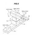
- the rotating gantry 1comprises a substantially cylindrical rotating drum (rotating body) 3 having a front ring 2, and a motor (rotating device), not shown, for rotating the rotating drum 3.
- the front ring 2 provided at one end of the rotating drum 3is supported by a plurality of rotatable support rolls 6.
- the support rolls 6are rotatably mounted to a support unit 10 installed on a rotating gantry installation area (building base) 9.
- the other ring(having an outer diameter equal to that of the front ring 2) provided at the other end of the rotating drum 3 is similarly supported by a plurality of support rolls 6 which are rotatably mounted to the other support unit 10.
- An inverted U-shaped beam transport system 5 serving as a part of the beam transport system 49 and the particle beam irradiation section 4are mounted on the rotating drum 3 and are rotated with the rotation of the rotating gantry 1.
- the beam transport system 5includes electromagnets, such as deflecting electromagnets 51, 52.
- a treatment gauge (treatment chamber) 14is formed inside the rotating drum 3.
- Fig. 4is a schematic view showing a vertical sectional structure of the particle beam irradiation section 4.
- the particle beam irradiation section 4comprises a casing 90 mounted to the rotating drum 3 and coupled to the inverted U-shaped beam transport system 5, and a snout 21 provided at one end of the casing 90, i.e., on the side nearer to the nozzle end.
- a scatterernot shown
- Those componentsare successively arranged to lie on a beam line m along which the ion beam passes.
- Additional unitssuch as an SOBP forming unit of ridge filter type and a range adjusting unit having a pair of wedge-shaped blocks, may also be disposed to lie on the beam line m.
- the ring collimator 22is to roughly collimate an irradiation field of the ion beam and is mounted to the snout 21 through a mounting member (not shown).
- the patient collimator 23is to shape the ion beam in match with the tumor shape in the direction perpendicular to the beam line m, and it is also mounted to the snout 21 through a mounting member (not shown).
- the ion beam formed by the particle beam irradiation section 4 of the above-described construction and having the proper irradiation fieldreleases its energy in the tumor in the body of the patient 8, thereby forming a high-dose area.
- an X-ray emission device (X-ray tube) 26 serving as an X-ray sourcewill be described later.
- the medical particle beam irradiation system 40includes an irradiation chamber 55 for the particle beam treatment in the rotating drum 3 of the rotating gantry 1.
- the irradiation chamber 55 for the particle beam treatmentis provided with a fixed annular frame (ring member) 15.
- the annular frame 15is disposed on one end side of the rotating drum 3, i.e., on the same side as the front ring 2, and is fixed to a mount base 18 installed in the rotating gantry installation area 9.
- the other annular frame(not shown) is disposed on the other end side of the rotating drum 3 so as to sandwich a path of movement of the particle beam irradiation section 4 between itself and the annular frame 15.
- the other annular frameis supported by a plurality of support rolls 20 which are rotatably held by a support frame 19 fixed to an inner surface of the rotating drum 3.
- the other annular frameis rotatable relative to the rotating drum 3 through the support rolls 20.
- These annular frames including the one 15have guide grooves (not shown) each comprising a lower horizontal portion and an upper arc-shaped portion, which are formed in respective side surfaces of the annular frames in an opposed relation to each other.
- Each of the guide grooveshas a substantially semicylindrical shape defined by the lower horizontal portion and the upper arc-shaped portion.
- the irradiation chamber 55 for the particle beam treatmentis further provided with a movable floor 17.
- the movable floor 17has a freely bendable articulated structure such that it comprises a number of plates 24 and every adjacent two of the plates 24 are coupled to each other by links (not shown).
- One end of the movable floor 17is engaged in the guide groove of the annular frame 15, and the other end of the movable floor 17 is engaged in the guide groove of the other annular frame.
- circumferential opposite ends of the movable floor 17are connected to the particle beam irradiation section 4.
- the particle beam irradiation section 4is also rotated in the same rotating direction as the rotating gantry 1.
- the movable floor 17 connected to the particle beam irradiation section 4is pulled together and moved in the same rotating direction.
- the movement of the movable floor 17is smoothly performed along the guide grooves of the annular frames including the one 15.
- the movable floor 17is made up of a horizontal floor portion 57 formed by the horizontal portions of the guide grooves in the lower side of the annular frames including the one 15, and an arc-shaped wall portion 58 formed by the arc-shaped portions of the guide grooves in the upper side of the annular frames including the one 15.
- the treatment gauge 14is formed within the movable floor 17.
- the treatment couch 59is inserted in the treatment gauge 14 when the ion beam is irradiated to the patient from the particle beam irradiation section 4.
- a treatment bench 7comprises a couch driver 12 and the treatment couch 59 installed on the couch driver 12.
- the treatment bench 7is installed outside the rotating gantry 1 in an opposed relation to the front ring 2 within a treatment couch installation area (not shown) located at a level elevated one step from the rotating gantry installation area 9 (see Fig. 3).
- the couch driver 12has four articulation axes 12A, 12B, 12C and 12D, and includes motors 11a, 11b, 11c and 11d for driving the treatment couch 59.
- Driving of the motor 11amoves the treatment couch 59 in the direction of the articulation axis 12A (X-axis) that is horizontally extended parallel to the front ring 2.
- Driving of the motor 11bmoves the treatment couch 59 in the direction of the articulation axis 12B (Z-axis) that is perpendicular to the articulation axis 12A.
- Driving of the motor 11cmoves the treatment couch 59 in the direction of the articulation axis 12C (Y-axis) that is perpendicular to both the articulation axis 12A (X-axis) and the articulation axis 12B (Z-axis) and is extended in the direction of a rotation axis of the rotating gantry 1.
- the treatment couch 59is moved into and out of the treatment gauge 14 with the driving of the motor 11c.
- driving of the motor 11drotates the treatment couch 59 about the articulation axis 12D ( ⁇ -axis) that is perpendicular to the articulation axis 12C (Y-axis).
- the patient positioning device of this embodimentis provided in the medical particle beam irradiation system 40 having the basic construction described above. The construction and functions of the patient positioning device will be described in detail below.
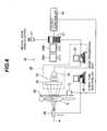
- a patient positioning device 28comprises an X-ray emission device (X-ray tube or source) 26, an X-ray image capturing device (image information generator) 29, an X-ray tube controller 36, a positioning data generator (positioning information generator) 37 having not-shown input means (such as a keyboard and a mouse), a medical image archive server 17, a couch controller 38, and display units 39A, 39B.
- the positioning data generator 37is constituted a work station (processing unit).
- the X-ray image capturing device 29comprises an X-ray fluorescence multiplier (X-ray image intensifier) 30, an optical system 33, and a CCD camera (image information producing unit) 34.
- a fluorescence film board 32is disposed on the side nearer to an inlet window 64, and an output fluorescence film 53 is disposed on the side nearer to an outlet window 63.
- the fluorescence film board 32has an input fluorescence film (X-ray entry device or X-ray transducer) 48 disposed on its rear side (i.e., on the side opposed to the inlet window 64).
- the output fluorescence film 53has a smaller diameter than the input fluorescence film 48.
- a photocathode 50is disposed in contact with the input fluorescence film 48.
- a converging electrode 54is disposed in the vacuum vessel 31 so as to surround a photoelectron path 65.
- An anode 60 surrounding the output fluorescence film 53is also disposed in the vacuum vessel 31.
- a voltageis applied between the photocathode 50 and the converging electrode 54 from a convergence power supply 56. Further, a voltage is applied between the photocathode 50 and the anode 60 from an anode power supply 61.
- the X-ray image capturing device 29is mounted to the rotating drum 3 of the rotating gantry 1 and is rotated together with the rotation of the rotating gantry 1.
- the X-ray image capturing device 29is positioned on the beam line m on the side opposed to the particle beam irradiation section 4 with respect to the treatment couch 59.
- the X-ray emission device 26is provided on a support member 16, which is mounted to the snout 21, to be movable in a direction perpendicular to the beam line m.
- the support member 16has an opening through which the ion beam and the X-ray pass.
- the X-ray emission device 26is retreated to a position P 1 away from the beam line m.
- an operatore.g., a doctor
- the couch controller 38controls the couch driver 12 to move the treatment couch 59 so that the cross mark on the patient's body surface is aligned with the beam line m. With this alignment, an offset between the tumor and the beam line m is held within the range on the order of millimeter.
- the operatorinputs a command for starting advance of the X-ray emission device 26 to an X-ray tube controller 36, e.g., a personal computer, through an input means (not shown).
- the X-ray tube controller 36having received the start command outputs an X-ray tube movement signal to a not-shown driver (e.g., a motor) for the X-ray emission device 26.
- a not-shown drivere.g., a motor
- the X-ray emission device 26is advanced to a position P 2 on the beam line m.
- an X-ray irradiation start signal outputted from the X-ray tube controller 36is inputted to the X-ray emission device 26.
- the X-ray emission device 26irradiates an X-ray beam toward the patient 8 along the beam line m.
- the X-ray having penetrated the patient 8is inputted to the vacuum vessel 31 through the inlet window 64 and then reaches the input fluorescence film 48 through the fluorescence film board 32 for conversion into a visible image.
- Light of the visible imageis converted into photoelectrons by the photocathode 50.
- the photoelectronsare converged by the converging electrode 54 and then reach the output fluorescence film 53 through the anode 60 along the photoelectron path 65 for conversion into a bright visible image.
- This bright visible imageis captured by the CCD camera 34 through lenses 62 in the optical system 33.
- the image captured by the CCD camera 34is inputted to a personal computer (image processing unit) 35 serving as a first processing unit.
- the image processing unit 35executes predetermined processing on the input image for the purpose of image processing (such as color correction and blur correction).
- Image dataalso called current image data or captured image data
- a tumor imagewhich has been subjected to the image processing
- the image processing unit 35is inputted to the positioning data generator 37 from the image processing unit 35.
- the positioning data generator 37produces positioning data for the treatment couch 59 based on the current image data outputted from the X-ray image capturing device 29 and image data stored in the medical image archive server 17, and then outputs the produced positioning data to the couch controller 38.
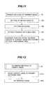
- a sequence of processing executed by the positioning data generator 37 to produce the positioning datawill be described below with reference to Fig. 8. This processing sequence is stored, as a program, in a memory (e.g., a not-shown ROM or other storage medium) provided in the positioning data generator 37.
- the medical image archive server 17accumulates and stores, as reference image data (control image data) serving as a positioning reference, data of a tomographic image of the relevant patient 8 captured by X-ray CT (e.g., a DRR image, or an X-ray image captured by the patient positioning device shown in Fig. 6 in advance, for example, until the day before the treatment day, or an image obtained by editing such an image using the known method in match with the direction in which the ion beam is now to be irradiated).
- the reference image datais first loaded into a memory (not shown) of the positioning data generator 37 from medical image archive server 17 (step 71).
- the expression “data (or information) is inputted to the positioning data generator 37"means that "the data (or information) is stored in the above-mentioned memory in the positioning data generator 37".
- the current image data of the tumorwhich is outputted from the image processing unit 35 after being subjected to the above-mentioned image processing, is also inputted to the positioning data generator 37 (step 72).
- the reference image data taken into the positioning data generator 37is outputted to the display unit (second display unit) 39A (step 73), and the current image data taken into the positioning data generator 37 is outputted to the display unit (first display units) 39B (step 74).
- a reference imageis displayed on the display unit 39A and a current image is displayed on the display unit 39B.
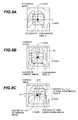
- Fig. 9(A)shows an example of a screen image of the reference image displayed on the display unit 39A
- Fig. 9(B)shows an example of a screen image of the current image displayed on the display unit 39B.
- the reference image displayed on the display unit 39A in step 73does not yet indicate a frame of a comparison area A.
- the current image displayed on the display unit 39B in step 74does not yet indicate a frame of a comparison area B.
- the reference image and the current imagemay be displayed on one display unit side by side or in a superposed relation instead of separately displaying them on the respective display units 39A, 39B.
- the reference image and the current imagemay be displayed on a display of the image processing unit 35.
- the operatorsets a predetermined comparison area (clipping area) A in the reference image displayed on the display unit 39A with the isocenter positioned at the center.
- the comparison area A(more exactly speaking, the frame of the comparison area A) is inputted for setting (clipping) by using the input unit of the positioning data generator 37.
- the comparison area Ais employed as an area for comparison with the current image having the center aligned with the beam line m through pattern matching.
- the input data for setting the comparison area Ais taken into the positioning data generator 37 (step 75).
- display information of the set comparison area A(more exactly speaking, the frame of the set comparison area A), i.e., display information of the frame of the comparison area A, is outputted to the display unit 39A (step 76).
- the data of the frame of the comparison area Ais displayed on the display unit 39A in a superposed relation to the reference image while the center of the comparison area A is aligned with the isocenter.
- Fig. 9(A)shows one practical example in which the data of the frame of the comparison area A is displayed on the reference image. A region inside the frame of the comparison area A defines the comparison area A.
- the positioning data generator 37instead of manually setting the comparison area A by the operator as described above, it is also possible to automatically set the comparison area A by the positioning data generator 37 (for example, through a step of automatically setting a preset area of a predetermined size with the isocener positioned at the center, or an area of a size variable depending on a treatment plan supplied from the medical image archive server 17).
- the positioning data generator 37sets a comparison area B (more exactly speaking, a frame of the comparison area B), which has the same size as the comparison area A, on the current image displayed on the display unit 39B with the origin defined at the center (beam line m) of the current image (step 77).
- the setting of the size of the comparison area Bis automatically performed using the setting input data that has been entered through the input unit of the positioning data generator 37 to set the comparison area A.
- the data of the comparison area B(more exactly speaking, the frame of the comparison area B) thus set is outputted to the display unit 39B (step 78).
- the data of the frame of the comparison area Bis displayed on the display unit 39B in a superposed relation to the current image while the center of the comparison area B is aligned with the center of the current image.
- Fig. 9(B)shows one practical example in which the frame of the comparison area B is displayed on the current image. A region inside the frame of the comparison area B defines the comparison area B. Note that the comparison area B may be set with manual setting made by the operator.
- the positioning data generator 37executes primary pattern matching between the comparison area A and the comparison area B based on image similarity searching (e.g., pattern matching through comparison of pixel information) utilizing correlation between two images (step 79).
- the comparison area A and the comparison area Bhave the same number of pixels in each of the X- and Y-directions, and also have the same total number of pixels in the respective entire areas.
- a search area 70(see Fig. 9(B)) is set which is smaller than the current image, but larger than the comparison area B (step 79A).
- pattern matchingis executed through comparison between pixel information of a reference image present inside the frame of the comparison area A (referred to as the reference image in the comparison area A) and pixel information of a current image present inside the frame of the comparison area B (referred to as the current image in the comparison area B) (step 79B). It is generally thought that an image is made up of a large number of pixels (see Figs. 10(A) and 10(B)) two-dimensionally arrayed in a mesh-like pattern, and pixel information (pixel value) is stored in each of the pixels. In this embodiment, the pattern matching between the current image and the reference image is executed by utilizing those pixel values.
- step 79Bthe pattern matching is first executed on the pixel values (scalar quantities) of all pixels of the current image included within the frame of the comparison area B and the pixel values of all pixels of the reference image included within the frame of the comparison area A while successively moving, e.g., translating, the frame of the comparison area B in the search area 70 in each of the X-and Y-directions. More specifically, in Fig. 9(B), an upper end of the frame of the comparison area B is aligned with an upper end of the search area 70, and an upper left corner of the frame of the comparison area B is aligned with an upper left corner of the search area 70.
- the pixel value for each of the pixels of the reference image in the comparison area A and the pixel value for each of the pixels of the current image in the comparison area Bare compared with each other while the pixels in both the images are made correspondent to each other in a one-to-one relation.
- This comparisonis performed through steps of computing a square value of a difference between the pixel value of each pixel of the reference image in the comparison area A and the pixel value of each pixel, corresponding to the above each pixel of the reference image, of the current image in the comparison area B for all the corresponding pixels in both the comparison areas, and then adding the thus-computed square values.
- the total sum resulting from the above additionrepresents a deviation between the reference image in the comparison area A and the current image in the comparison area B set in the aforesaid position
- the aforesaid comparisonrepresents an arithmetic operation for computing a deviation between the pixel values of all the corresponding pixels included in both the images and compared with each other.
- Such a deviationis repeatedly computed for each position of the comparison area B while successively translating the frame of the comparison area B to the right (in the X-direction) on the one-pixel by one-pixel basis.
- the right end of the frame of the comparison area Breaches the right end of the search area 70 with the movement of the frame of the comparison area B in the X-direction
- the upper end of the frame of the comparison area Bis translated by a distance of one pixel downward (in the Y-direction).
- a similar deviationis computed in the same manner as described above for each position of the comparison area B while successively translating the frame of the comparison area B to the right (in the X-direction) on the one-pixel by one-pixel basis.
- the movement of the frame of the comparison area B in the Y-axisis repeated.
- the movement of the frame of the comparison area Bis performed until the lower end and the lower right corner of the frame of the comparison area B are aligned respectively with the lower end and the lower right corner of the search area 70, whereby the above-described deviation is computed for each position of the frame of the comparison area B.
- a primary matching area having an image similar to the reference image in the comparison area Ais extracted (step 79C). More specifically, the comparison area B is extracted of which deviation has the smallest value among all of the deviations computed in step 79B through the pattern matching performed for each position of the frame of the comparison area B.
- the extracted comparison area Bwill be referred to as a final comparison area B.
- the current image in the final comparison area Bis most similar to the reference image in the comparison area A.
- the final comparison area Bis the primary matching area.
- a position offset between the center (beam line m) of the current image and the center of the final comparison area B (primary matching area)is then computed (step 79D).
- such a position offsetis computed by using coordinate values (X c , Y c ) of the center of the current image and coordinate values (X rc , Y rc ) of the center of the final comparison area B to obtain a position offset ⁇ X1 in the X-direction between the center of the current image and the center of the final comparison area B and a position offset ⁇ Y1 in the Y-direction between the center of the current image and the center of the final comparison area B.
- the position offsets ⁇ X1, ⁇ Y1are stored in the memory provided in the positioning data generator 37.
- the primary pattern matchingis performed based on the reference image in the comparison area A and the current image in the comparison area B each having a restricted two-dimensional range, the time required for the pattern matching can be cut down.
- the primary pattern matchingis performed by linearly moving the comparison area B in the X- and Y-directions without rotating the comparison area B, and this pattern matching method also contributes to cutting down the time required for the pattern matching.
- a superposition deviation(residual error) is computed from pixel information of all meshes. Then, the position of the comparison area B where the computed residual error is minimum is determined while moving the comparison area B in the up-and-down direction and the left-and-right direction.
- comparison area Btarget pattern
- comparison area Amaster pattern
- normalized distributions of pixel information of all meshesare separately computed. Then, the position of the comparison area B where a value of the correlation coefficient between the two computed distributions is maximum is determined while moving the comparison area B in the up-and-down direction and the left-and-right direction.
- This methodrequires a longer computing time than the residual error matching of above (1), but practical processing can be performed with speed-up through division of the distribution into layers.
- comparison area Btarget pattern
- comparison area Amaster pattern
- pixel information patterns of all meshesare separately subjected to Fourier transformation. Then, phase-only processing is performed on the Fourier transformation plane to determine a matching point between both the patterns.
- thisis a matching method utilizing a series of edge points. This method enables the matching to be performed without being affected by overlapping and hiding.
- This matching methodutilizes a series of edge points similarly to the above methods (4) and (5), and enables the matching to be performed without being affected by rotation and resizing, as well as by overlapping and hiding.
- any other suitable onee.g., the least square method used in step 81 described later, may also be used to perform the primary pattern matching.
- the data of the frame of the final comparison area B extracted through the primary pattern matchingis outputted to the display unit 39B (step 80).
- the frame of the final comparison area Bis displayed on the display unit 39B together with the information of the current image (see Fig. 9C).
- Secondary pattern matching for the current image in the final comparison area Bis executed by employing just the reference image in the comparison area A and the current image in the final comparison area B (step 81). In other words, the entire regions of the reference image and the current image are not used here.
- the primary matching area (final comparison area B) obtained through the primary pattern matchingis employed as a secondary matching candidate area. Then, based on the reference image in the comparison area A and the current image in the secondary matching candidate area (final comparison area B), the positioning data generator 37 executes coordinate transformation of the current image in the final comparison area B and finely determines the amounts of translation in the X- and Y-directions and the amount of a rotational angle at which both the images are most matched with each other. Practically, the secondary pattern matching is performed in this embodiment by using the least square method.
- step 81Aa similar area, i.e., the current image in the comparison area B, is moved and rotated (step 81A).
- the current image in the comparison area Bis subjected to coordinate transformation by using coordinate transformation coefficients.
- the amount of translation and the amount of a rotational anglecan be designated as the coordinate transformation coefficients.
- the movement of the comparison area Bis performed by translating the current image in the final comparison area B in the X- and Y-directions and rotating it until the center of the final comparison area B (i.e., the position at which two diagonals of the final comparison area B cross each other) (see Fig.
- step 81Bpattern matching is executed (step 81B).
- the least square methodis employed to evaluate similarity (degree of matching) between the reference image in the comparison area A the current image in the final comparison area B. More specifically, in a state of Fig. 10(B), the current image in the final comparison area B is translated in the X- and Y-directions and rotated in step 81A with respect to the reference image in the comparison area A, and the degree of matching between the moved current image in the final comparison area B and the reference image in the comparison area A is evaluated.
- the pattern matchingis made on the reference image in the comparison area A and the current image in the comparison area B (final comparison area B) each having a restricted two-dimensional range, processing for the pattern matching can be executed in a non-wasteful manner and hence the processing time required for the pattern matching can be cut down.
- the processing for the pattern matching in step 81Awill be described below. It is here assumed that the position of a pixel of the reference image in the comparison area A is A(X, Y) and the position of a pixel, corresponding to the above pixel of the reference image, of the current image in the final comparison area B is B(X', Y'). Thus, the position of each pixel is expressed, by way of example, as follows.
- the position of a pixel locating at an upper left corner of the reference image in the comparison area Ais expressed by coordinate values of A(1, 1)
- the position of a pixel locating at an upper left corner of the current image in the final comparison area Bis expressed by coordinate values of B(1, 1).
- a square value of a difference (deviation) between the pixel value of each pixel A(X, Y) and the pixel value of each corresponding pixel B(X', Y')is computed for each pair of all the corresponding pixels in both the reference image in the comparison area A and the current image in the final comparison area B, and the thus-computed square values are added to determine the total sum. Then, while repeating the processing sequence of step 81A, i.e., translating the current image in the final comparison area B in the X- and Y-directions and rotating it with respect to the reference image in the comparison area A, the above-mentioned total sum is successively computed in step 81B.
- the coordinate transformation coefficients providing the minimum total sumare obtained.
- the thus-obtained coordinate transformation coefficientsrepresent a position offset of the final position of the current image in the final comparison area B with respect to the reference image in the comparison area A, i.e., a position offset ⁇ X2 in the X-direction, a position offset ⁇ Y2 in the Y-direction, and a rotation amount (angle) ⁇ .
- the position offsets ⁇ X2, ⁇ Y2 and the rotation amount ⁇are all stored in the memory provided in the positioning data generator 37.
- the pattern matchingis performed on the current image in the comparison area B having a restricted two-dimensional range and the reference image in the comparison area A also having a restricted two-dimensional range while translating the current image in the primary matching area (final comparison area B) in the X- and Y-directions and rotating it.
- the time required for the pattern matchingcan be cut down even with the matching process including the image rotation.
- the method used for executing the secondary pattern matchingis not limited to the least square method described above, and the secondary pattern matching may be performed by using any other suitable method, for example, by executing one of the above-mentioned methods (1) to (6) again.
- the data of the current image in the final comparison area Bwhich is located in the final position of the current image determined through the secondary pattern matching, is outputted to the display unit 39A (step 82).
- the current image in that final positionis displayed (though not shown) on the display unit 39A in a superposed relation to the reference image in the comparison area A.
- the operatorsuch as the doctor, can visually confirm the aligned state of the tumor.
- couch (patient) positioning datais produced (step 83).
- Couch movement amounts (couch movement information) constituting the couch positioning dataare computed by using the position offsets ⁇ X1, ⁇ Y1, ⁇ X2 and ⁇ Y2 and the rotation amount ⁇ which are all stored in the memory provided in the positioning data generator 37. More specifically, a couch movement amount ⁇ X in the X-direction is computed as ( ⁇ X1 + ⁇ X2), a couch movement amount ⁇ Y in the Y-direction is computed as ( ⁇ Y1 + ⁇ Y2), and a couch movement amount (couch rotation amount) ⁇ in the rotating direction is computed as ⁇ . These couch movement amounts ⁇ X, ⁇ Y and ⁇ constitute couch positioning information used for the positioning of the couch. This couch positioning information serves also as the couch movement information. Subsequently, in step 83, the couch movement amounts ⁇ X, ⁇ Y and ⁇ are outputted to and displayed on the display unit 39A.
- the doctordetermines whether the treatment couch 59 is to be moved to execute again for alignment of the tumor. If the doctor determines that the operation for alignment of the tumor is required with the movement of the treatment couch 59, the doctor inputs information indicative of "necessity of couch movement" to the positioning data generator 37 by using the input unit (not shown), the input information being separated into data per X-direction, Y-direction and rotating direction. On the other hand, if the doctor determines that the operation for aligning the tumor is not required with the movement of the treatment couch 59, the doctor inputs information indicative of "non-necessity of couch movement" to the positioning data generator 37 by using the input unit.
- the positioning data generator 37determines whether the "couch is to be moved" (step 84). More specifically, if the information inputted from the input unit indicates "non-necessity of couch movement", this means that the tumor is positioned on the beam line m. Hence, the movement of the treatment couch 59, i.e., the alignment of the tumor in the body of the patient 8 with the beam line m, is not performed by the couch driver 12, and the couch positioning process is completed. On the other hand, if the information inputted from the input unit indicates "necessity of couch movement", the couch positioning information is outputted to the couch controller 38 (step 85). Practically, the couch movement amounts ⁇ X, ⁇ Y and ⁇ obtained in above step 83 are sent to the couch controller 38. The couch movement amounts ⁇ X, ⁇ Y and ⁇ constitute information used for the positioning of the treatment couch 59. Thereafter, the alignment of the tumor is performed through the movement of the treatment couch 59 as described later.
- step 84it is also possible to determine in step 84 as to "whether the couch movement amount is equal to a preset movement value (e.g., a movement value 0)" instead of "whether the couch is to be moved", and to instruct the positioning data generator 37 to carry out the movement of the couch.
- a preset movement valuee.g., a movement value 0
- the movement of the treatment couch 59i.e., the alignment of the tumor in the body of the patient 8 with the beam line m, is not performed by the couch driver 12, and the couch positioning process is completed.
- the processing of step 85is performed and the couch positioning information is outputted to the couch controller 38.
- the couch movement amounts ⁇ X, ⁇ Y and ⁇ obtained in step 83are sent to the couch controller 38.
- modified step 84information indicating the determination result, i.e., "completion of the patient positioning” or "re-execution of the patient positioning” is outputted to and displayed on, for example, the display unit 39A.
- the couch movement amounts ⁇ X, ⁇ Y and ⁇are outputted to and displayed on the display unit 39A.
- the couch controller 38receives respective detected data regarding X- and Y-directional positions (X0, Y0) of the treatment couch 59 and a rotational angle (e.g., ⁇ 0) thereof in the rotating direction in the state before the X-ray is irradiated from the X-ray emission device 26 as described above. Those data are detected by respective sensors (not shown) disposed on the couch driver 12. Also, the couch controller 38 receives the couch movement amounts ⁇ X, ⁇ Y and ⁇ and compute the position of the treatment couch 59, i.e., (X0 + ⁇ X), (Y0 + ⁇ Y) and ( ⁇ 0 + ⁇ ), to which it is to be moved. Then, the couch controller 38 drives the motors 11a, 11c and 11d to move the treatment couch 59 so that the position of the tumor in the body of the patient 8 lying on the treatment couch 59 is aligned with the computed position.
- a rotational anglee.g., ⁇ 0
- step 84After moving the treatment couch 59 in such a manner, the X-ray irradiation along the beam line m is performed on the patient 8 again, and the processing of steps 72 to 84 are repeated by the positioning data generator 37 using the current image captured by the X-ray image capturing device 29 until the information "non-necessity of couch movement" is inputted in step 84.
- pattern matchingis performed on the reference image in the set comparison area A and the current image in the set comparison area B to produce information for the positioning of the patient (couch).
- the positions of the monuments or the likesmust be designated on each of the reference image and the current image at high accuracy without an offset between the reference image and the current image.
- the operatorsince the reference image in the set comparison area A and the current image in the set comparison area B are subjected to the pattern matching, the operator is not required to designate the positions of the monuments or the likes, and hence the accuracy in producing the patient positioning data is avoided from being affected by the skills of individual operators. Accordingly, the patient positioning accuracy can be increased regardless of the skills of individual operators. As a result, a patient positioning device can be constructed of which operation does not depend upon amounts of the skills of individual operators. Further, it is possible to cut the time and labor required for setting the monuments or the likes, and to quickly and smoothly carry out the positioning operation.
- the movement amount of the treatment couch 59(specifically the movement amount of the tumor in the body of the patient 8 lying on the treatment couch 59) is determined through pattern matching made on a plurality of corresponding areas (e.g., pixels) in both the above-mentioned images, the positioning accuracy of the treatment couch 59 with respect to the beam line m is further increased.
- the pattern matching between the reference image and the current imageis performed by using respective image information (pixel values of respective pixels) specific to the reference image and the current image, there is no need of adding new information for the pattern matching.
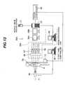
- an X-ray image capturing device (image information generator) 29Amay be used instead of the X-ray image capturing device 29 shown in Fig. 13.
- a patient positioning device 28A using the X-ray image capturing device 29Awill be described below with reference to Fig. 13.
- the patient positioning device 28Adiffers from the above-described patient positioning device 28 in using the X-ray image capturing device 29A.
- the X-ray image capturing device 29Acomprises a plurality of semiconductor radiation detectors (X-ray entry devices or flat panel detector) 66, a plurality of signal amplifiers 67, a plurality of signal processors 68, and an image processing unit (image information producing unit) 69.
- the plurality of semiconductor radiation detectors 66are arranged in a grid pattern comprising a plurality of rows in the X-direction and a plurality of columns in the Y-direction, which are arrayed in a closely contacted state with each other.
- the signal amplifiers 67 and the signal processors 68are disposed in a one-to-one relation to the semiconductor radiation detectors 66 and are serially connected to corresponding ones of the semiconductor radiation detectors 66.
- Information outputted from the individual signal processors 68 and indicating the intensity of X-rayis sent to the image processing unit 69.
- An X-ray beam for detecting the tumor in the body of the patient 8is emitted from the X-ray emission device 26, which has been moved to position on the beam line m, and penetrates the tumor and the surroundings thereof. Then, the X-ray beam enters the flat panel detector (all the semiconductor radiation detectors 66) disposed on the side of the treatment couch 59 away from the patient 8 for conversion into electrical signals.
- the electrical signal outputted from each of the semiconductor radiation detectors 66is amplified by the corresponding signal amplifier 67 and is integrated by the corresponding signal processor 68 for a preset interval of time. As a result of integrating the electrical signal, X-ray intensity information is obtained.
- the image processing unit 69produces image information (information of a current image or a captured image) by using the X-ray intensity information outputted from each signal processor 68.
- the information of the current imageis taken into the positioning data generator 37, which executes similar processing to that described in the above embodiment.
- This modified embodimentcan also provide similar advantages as those obtained with the above embodiment.
Landscapes
- Health & Medical Sciences (AREA)
- Life Sciences & Earth Sciences (AREA)
- Engineering & Computer Science (AREA)
- Biomedical Technology (AREA)
- Medical Informatics (AREA)
- Veterinary Medicine (AREA)
- Public Health (AREA)
- General Health & Medical Sciences (AREA)
- Nuclear Medicine, Radiotherapy & Molecular Imaging (AREA)
- Animal Behavior & Ethology (AREA)
- Pathology (AREA)
- Radiology & Medical Imaging (AREA)
- Biophysics (AREA)
- Heart & Thoracic Surgery (AREA)
- Molecular Biology (AREA)
- Surgery (AREA)
- Optics & Photonics (AREA)
- High Energy & Nuclear Physics (AREA)
- Physics & Mathematics (AREA)
- Human Computer Interaction (AREA)
- Radiation-Therapy Devices (AREA)
Abstract
Description
Claims (18)
- A patient positioning device for positioning acouch supporting a patient to which a charged particle beamis irradiated from a particle beam irradiation system, saidpatient positioning device comprising:an X-ray emission device mounted to said particle beamirradiation system, being movable between a first positionlocated in a path of said charged particle beam and a secondposition located away from the path of said charged particlebeam to be out of interference with advance of said chargedparticle beam, and emitting an X-ray in said first position;an X-ray entry device for receiving the X-ray emittedfrom said X-ray emission device and outputting an outputsignal depending on the received X-ray;an image information generator for generating secondimage information regarding a portion of the patient lyingacross the path of said charged particle beam by using theoutput signal outputted from said X-ray entry device; anda processing unit for executing pattern matchingbetween a part of first image information in a first setarea including an isocenter, the first image informationrepresenting a tumor in the body of the patient and servingas a reference including the isocenter, and a part of thesecond image information in a second set area including aposition corresponding to the path of said charged particlebeam, thereby producing information used for positioning ofsaid couch.
- A patient positioning device according to Claim 1,further comprising a couch controller for controllingmovement of said couch in accordance with said positioninginformation.
- A patient positioning device according to Claim 1,wherein said processing unit executes the pattern matchingby using information of a plurality of pixels contained inthe first image information in said first set area andinformation of a plurality of pixels contained in the secondimage information in said second set area.
- A patient positioning device according to Claim 3,wherein said processing unit produces said positioninginformation based on the least square method such that adeviation between the information of a plurality of pixelscontained in the first image information in said first setarea and the information of a plurality of pixels containedin the second image information in said second set area isminimized.
- A patient positioning device for positioning acouch supporting a patient to which a charged particle beamis irradiated from a particle beam irradiation system, saidpatient positioning device comprising:an X-ray emission device mounted to said particle beamirradiation system, being movable between a first position located in a path of said charged particle beam and a secondposition located away from the path of said charged particlebeam to be out of interference with advance of said chargedparticle beam, and emitting an X-ray in said first position;an image information generator for generating secondimage information regarding a portion of the patient lyingacross the path of said charged particle beam by using asignal depending on the X-ray emitted from said X-rayemission device;a display unit for displaying first image informationrepresenting a tumor in the body of the patient and servingas a reference including the isocenter, and the second imageinformation; anda processing unit for setting a first set areaincluding the isocenter with respect to the first imageinformation, setting a second set area including a positioncorresponding to the path of said charged particle beam withrespect to the second image information, executing patternmatching between the first image information in said firstset area and the second image information in said second setarea, producing information used for positioning of saidcouch, and outputting information for displaying respectiveframes of said first set area and said second set area tosaid display unit.
- A patient positioning device according to Claim 5,wherein said display unit comprises a first display unit fordisplaying the first image information and a second display unit for displaying the second image information, saidsecond display unit being separate from said first displayunit.
- A patient positioning device according to Claim 5,wherein said image information generator comprises an X-raytransducer for converting the incident X-ray into light, anda camera for capturing the light and producing the secondimage information.
- A patient positioning device according to Claim 5,wherein said image information generator comprises aplurality of semiconductor radiation detectors forconverting the incident X-ray into electrical signals, aplurality of signal processors disposed in a one-to-onerelation to said semiconductor radiation detectors andprocessing said electrical signals, and an image informationproducing unit for receiving outputs from said signalprocessors and producing the second image information.
- A patient positioning device according to Claim 5,wherein said processing unit executes the pattern matchingby using information of a plurality of pixels contained inthe first image information in said first set area andinformation of a plurality of pixels contained in the secondimage information in said second set area.
- A patient positioning device according to Claim 9, wherein said processing unit produces said positioninginformation based on the least square method such that adeviation between the information of a plurality of pixelscontained in the first image information in said first setarea and the information of a plurality of pixels containedin the second image information in said second set area isminimized.
- A patient positioning device for positioning acouch supporting a patient to which a charged particle beamis irradiated from a particle beam irradiation system, saidpatient positioning device comprising:an X-ray emission device mounted to said particle beamirradiation system, being movable between a first positionlocated in a path of said charged particle beam and a secondposition located away from the path of said charged particlebeam to be out of interference with advance of said chargedparticle beam, and emitting an X-ray in said first position;an image information generator for generating secondimage information regarding a portion of the patient lyingacross the path of said charged particle beam by using asignal depending on the X-ray emitted from said X-rayemission device; anda processing unit for setting a first set areaincluding an isocenter with respect to first imageinformation representing a tumor in the body of the patientand serving as a reference including the isocenter, setting,with respect to the second image information, a second set area having substantially the same size as said first setarea and including a position corresponding to the path ofsaid charged particle beam, executing primary patternmatching between the first image information in said firstset area and the second image information in said second setarea to determine a primary matching area with respect tothe second image information, and executing secondarypattern matching between the first image information in saidfirst set area and the second image information in saidprimary matching area, thereby producing information usedfor positioning of said couch.
- A patient positioning device according to Claim 11,further comprising a couch controller for controllingmovement of said couch in accordance with said positioninginformation.
- A patient positioning device according to Claim 11,wherein said processing unit executes the pattern matchingby using information of a plurality of pixels contained inthe first image information in said first set area andinformation of a plurality of pixels contained in the secondimage information in said second set area.
- A patient positioning device according to Claim 13,wherein said processing unit produces said positioninginformation based on the least square method such that adeviation between the information of a plurality of pixels contained in the first image information in said first setarea and the information of a plurality of pixels containedin the second image information in said second set area isminimized.
- A patient positioning device according to Claim 11,further comprising a display unit for displaying the firstimage information at least in said first set area and thesecond image information at least in said second set area,
wherein said processing unit outputs information fordisplaying respective frames of said first set area and saidsecond set area to said display unit. - A patient positioning device according to Claim 11,wherein said display unit comprises a first display unit fordisplaying the first image information and a second displayunit for displaying the second image information, saidsecond display unit being separate from said first displayunit.
- A patient positioning method for positioning acouch supporting a patient to which a charged particle beamis irradiated from a particle beam irradiation system, saidpatient positioning method comprising the steps of:moving an X-ray emission device for emitting an X-rayto be located in a path of said charged particle beam;irradiating the X-ray emitted from said X-ray emissiondevice to a tumor in the body of the patient on said couch along the path of said charged particle beam;generating, based on the X-ray having penetrated aportion of the patient lying across the path of said chargedparticle beam, second image information regarding theportion of the patient;taking, into a processing unit, first image informationrepresenting the tumor in the body of the patient andserving as a reference including the isocenter;taking second image information into said processingunit;executing, by utilizing said processing unit, patternmatching between a part of the first image information in afirst set area including the isocenter and a part of thesecond image information in a second set area including aposition corresponding to the path of said charged particlebeam, thereby producing information used for positioning ofsaid couch.
- A patient positioning method for positioning acouch supporting a patient to which a charged particle beamis irradiated from a particle beam irradiation system, saidpatient positioning method comprising the steps of:moving an X-ray emission device for emitting an X-rayto be located in a path of said charged particle beam;irradiating the X-ray emitted from said X-ray emissiondevice to a tumor in the body of the patient on said couchalong the path of said charged particle beam;generating, based on the X-ray having penetrated a portion of the patient lying across the path of said chargedparticle beam, second image information regarding theportion of the patient;setting a first set area including an isocenter withrespect to first image information representing the tumor inthe body of the patient and serving as a reference includingthe isocenter;setting, with respect to the second image information,a second set area having substantially the same size as saidfirst set area and including a position corresponding to thepath of said charged particle beam;executing primary pattern matching between the firstimage information in said first set area and the secondimage information in said second set area to determine aprimary matching area with respect to the second imageinformation; andexecuting secondary pattern matching between the firstimage information in said first set area and the secondimage information in said primary pattern matching area,thereby producing information used for positioning of saidcouch.
Priority Applications (1)
| Application Number | Priority Date | Filing Date | Title |
|---|---|---|---|
| DE602004009122TDE602004009122T3 (en) | 2003-03-05 | 2004-01-29 | Device for positioning a patient |
Applications Claiming Priority (2)
| Application Number | Priority Date | Filing Date | Title |
|---|---|---|---|
| JP2003058199 | 2003-03-05 | ||
| JP2003058199AJP3748433B2 (en) | 2003-03-05 | 2003-03-05 | Bed positioning device and positioning method thereof |
Publications (3)
| Publication Number | Publication Date |
|---|---|
| EP1454653A1true EP1454653A1 (en) | 2004-09-08 |
| EP1454653B1 EP1454653B1 (en) | 2007-09-26 |
| EP1454653B2 EP1454653B2 (en) | 2011-09-14 |
Family
ID=32821199
Family Applications (1)
| Application Number | Title | Priority Date | Filing Date |
|---|---|---|---|
| EP04001952AExpired - LifetimeEP1454653B2 (en) | 2003-03-05 | 2004-01-29 | Patient positioning device |
Country Status (6)
| Country | Link |
|---|---|
| US (2) | US7212608B2 (en) |
| EP (1) | EP1454653B2 (en) |
| JP (1) | JP3748433B2 (en) |
| KR (1) | KR100695377B1 (en) |
| AU (1) | AU2004200350A1 (en) |
| DE (1) | DE602004009122T3 (en) |
Cited By (32)
| Publication number | Priority date | Publication date | Assignee | Title |
|---|---|---|---|---|
| EP1683545A2 (en) | 2005-01-24 | 2006-07-26 | Hitachi, Ltd. | Ion beam therapy system and couch positioning method |
| EP1702650A1 (en)* | 2005-03-14 | 2006-09-20 | Hitachi, Ltd. | Patient positioning system and method |
| US7173265B2 (en) | 2003-08-12 | 2007-02-06 | Loma Linda University Medical Center | Modular patient support system |
| WO2006136947A3 (en)* | 2005-06-22 | 2007-03-08 | Emedica S L | Method and system for validating an external radiotherapy treatment |
| US7199382B2 (en) | 2003-08-12 | 2007-04-03 | Loma Linda University Medical Center | Patient alignment system with external measurement and object coordination for radiation therapy system |
| WO2008142695A1 (en)* | 2007-05-24 | 2008-11-27 | P-Cure Ltd. | Irradiation treatment apparatus and method |
| EP2005806A4 (en)* | 2006-04-07 | 2010-04-21 | Varian Med Sys Inc | Patient setup using tomosynthesis techniques |
| EP2243515A1 (en) | 2009-04-22 | 2010-10-27 | Ion Beam Applications | Charged particle beam therapy system having an X-Ray imaging device |
| US7847275B2 (en) | 2007-05-24 | 2010-12-07 | Pcure Ltd. | Method and apparatus for teletherapy positioning and validation |
| CN102883777A (en)* | 2010-02-10 | 2013-01-16 | 株式会社东芝 | Particle beam irradiation device and control method for particle beam irradiation device |
| US8565378B2 (en) | 2005-05-06 | 2013-10-22 | Deutsches Krebsforschungszentrum Stiftung Des Oeffentlichen Rechts | Method and device for defining a beam of high-energy rays |
| WO2014041004A1 (en) | 2012-09-11 | 2014-03-20 | Ion Beam Applications S.A. | Hadron therapy installation comprising an imaging device |
| US9406411B2 (en) | 2011-02-08 | 2016-08-02 | Accuray Incorporated | Automatic calibration for device with controlled motion range |
| US9622335B2 (en) | 2012-09-28 | 2017-04-11 | Mevion Medical Systems, Inc. | Magnetic field regenerator |
| US9661736B2 (en) | 2014-02-20 | 2017-05-23 | Mevion Medical Systems, Inc. | Scanning system for a particle therapy system |
| US9681531B2 (en) | 2012-09-28 | 2017-06-13 | Mevion Medical Systems, Inc. | Control system for a particle accelerator |
| US9706636B2 (en) | 2012-09-28 | 2017-07-11 | Mevion Medical Systems, Inc. | Adjusting energy of a particle beam |
| US9723705B2 (en) | 2012-09-28 | 2017-08-01 | Mevion Medical Systems, Inc. | Controlling intensity of a particle beam |
| US9730308B2 (en) | 2013-06-12 | 2017-08-08 | Mevion Medical Systems, Inc. | Particle accelerator that produces charged particles having variable energies |
| US9925395B2 (en) | 2005-11-18 | 2018-03-27 | Mevion Medical Systems, Inc. | Inner gantry |
| US9950194B2 (en) | 2014-09-09 | 2018-04-24 | Mevion Medical Systems, Inc. | Patient positioning system |
| US9962560B2 (en) | 2013-12-20 | 2018-05-08 | Mevion Medical Systems, Inc. | Collimator and energy degrader |
| US10155124B2 (en) | 2012-09-28 | 2018-12-18 | Mevion Medical Systems, Inc. | Controlling particle therapy |
| US10254739B2 (en) | 2012-09-28 | 2019-04-09 | Mevion Medical Systems, Inc. | Coil positioning system |
| US10258810B2 (en) | 2013-09-27 | 2019-04-16 | Mevion Medical Systems, Inc. | Particle beam scanning |
| US10646728B2 (en) | 2015-11-10 | 2020-05-12 | Mevion Medical Systems, Inc. | Adaptive aperture |
| US10653892B2 (en) | 2017-06-30 | 2020-05-19 | Mevion Medical Systems, Inc. | Configurable collimator controlled using linear motors |
| USRE48047E1 (en) | 2004-07-21 | 2020-06-09 | Mevion Medical Systems, Inc. | Programmable radio frequency waveform generator for a synchrocyclotron |
| US10675487B2 (en) | 2013-12-20 | 2020-06-09 | Mevion Medical Systems, Inc. | Energy degrader enabling high-speed energy switching |
| US10925147B2 (en) | 2016-07-08 | 2021-02-16 | Mevion Medical Systems, Inc. | Treatment planning |
| US11103730B2 (en) | 2017-02-23 | 2021-08-31 | Mevion Medical Systems, Inc. | Automated treatment in particle therapy |
| US11291861B2 (en) | 2019-03-08 | 2022-04-05 | Mevion Medical Systems, Inc. | Delivery of radiation by column and generating a treatment plan therefor |
Families Citing this family (160)
| Publication number | Priority date | Publication date | Assignee | Title |
|---|---|---|---|---|
| CA2465511C (en) | 2001-10-30 | 2007-12-18 | Loma Linda University Medical Center | Method and device for delivering radiotherapy |
| US7073508B2 (en) | 2004-06-25 | 2006-07-11 | Loma Linda University Medical Center | Method and device for registration and immobilization |
| DE102004062473B4 (en)* | 2004-09-30 | 2006-11-30 | Siemens Ag | Medical radiation therapy arrangement |
| EP1709994A1 (en)* | 2005-04-04 | 2006-10-11 | Ion Beam Applications S.A. | Patient positioning imaging device and method |
| EP1871477B1 (en)* | 2005-03-09 | 2011-03-23 | Paul Scherrer Institut | System for taking wide-field beam-eye-view (bev) x-ray-images simultaneously to the proton therapy delivery |
| EP1720173A1 (en)* | 2005-05-06 | 2006-11-08 | Deutsches Krebsforschungszentrum Stiftung des öffentlichen Rechts | Collimator for collimating a beam of high energy rays |
| DE102005030609A1 (en)* | 2005-06-30 | 2007-01-04 | Siemens Ag | Method or X-ray device for creating a series recording of medical X-ray images of a possibly moving patient during the series recording |
| DE102005036564A1 (en)* | 2005-08-03 | 2007-02-22 | Siemens Ag | Operating method for an imaging medical device and corresponding articles |
| JP4386288B2 (en) | 2005-08-31 | 2009-12-16 | 株式会社日立製作所 | Radiotherapy apparatus positioning system and positioning method |
| DE102005053971B4 (en)* | 2005-11-11 | 2009-08-27 | Siemens Ag | Particle therapy system with a fluoroscopy system for continuous acquisition of fluoroscopic image data |
| CN101112318B (en)* | 2006-07-28 | 2010-05-12 | Ge医疗系统环球技术有限公司 | Radiography equipment and method for arranging the rotating plane |
| ATE479398T1 (en)* | 2006-09-11 | 2010-09-15 | Koninkl Philips Electronics Nv | SYSTEM AND METHOD FOR POSITIONING ELECTRODES ON A PATIENT'S BODY |
| US8045677B2 (en)* | 2006-09-25 | 2011-10-25 | Koninklijke Philips Electronics N V Eindhoven | Shifting an object for complete trajectories in rotational X-ray imaging |
| JP5448831B2 (en) | 2006-11-21 | 2014-03-19 | ローマ リンダ ユニヴァーシティ メディカル センター | Apparatus and method for securing a patient for breast radiation therapy |
| DE102007011399A1 (en)* | 2007-03-08 | 2008-09-11 | Siemens Ag | Particle therapy facility |
| JP4941974B2 (en)* | 2007-03-20 | 2012-05-30 | 株式会社日立製作所 | Radiation therapy bed positioning system, treatment planning apparatus, and bed positioning apparatus |
| CN101340811B (en)* | 2007-07-06 | 2010-12-08 | 鸿富锦精密工业(深圳)有限公司 | Image Optimal Matching System and Method |
| US8003964B2 (en) | 2007-10-11 | 2011-08-23 | Still River Systems Incorporated | Applying a particle beam to a patient |
| US8581523B2 (en) | 2007-11-30 | 2013-11-12 | Mevion Medical Systems, Inc. | Interrupted particle source |
| US8933650B2 (en) | 2007-11-30 | 2015-01-13 | Mevion Medical Systems, Inc. | Matching a resonant frequency of a resonant cavity to a frequency of an input voltage |
| WO2009105703A1 (en) | 2008-02-22 | 2009-08-27 | Loma Linda University Medical Center | Systems and methods for characterizing spatial distortion in 3d imaging systems |
| JP5002488B2 (en)* | 2008-02-26 | 2012-08-15 | 株式会社日立製作所 | Bed positioning system and radiotherapy apparatus |
| US8896239B2 (en) | 2008-05-22 | 2014-11-25 | Vladimir Yegorovich Balakin | Charged particle beam injection method and apparatus used in conjunction with a charged particle cancer therapy system |
| US8436327B2 (en) | 2008-05-22 | 2013-05-07 | Vladimir Balakin | Multi-field charged particle cancer therapy method and apparatus |
| US8373145B2 (en) | 2008-05-22 | 2013-02-12 | Vladimir Balakin | Charged particle cancer therapy system magnet control method and apparatus |
| US7953205B2 (en)* | 2008-05-22 | 2011-05-31 | Vladimir Balakin | Synchronized X-ray / breathing method and apparatus used in conjunction with a charged particle cancer therapy system |
| CA2725493C (en) | 2008-05-22 | 2015-08-18 | Vladimir Yegorovich Balakin | Charged particle cancer therapy beam path control method and apparatus |
| US8688197B2 (en)* | 2008-05-22 | 2014-04-01 | Vladimir Yegorovich Balakin | Charged particle cancer therapy patient positioning method and apparatus |
| US8288742B2 (en)* | 2008-05-22 | 2012-10-16 | Vladimir Balakin | Charged particle cancer therapy patient positioning method and apparatus |
| US8399866B2 (en) | 2008-05-22 | 2013-03-19 | Vladimir Balakin | Charged particle extraction apparatus and method of use thereof |
| US7940894B2 (en)* | 2008-05-22 | 2011-05-10 | Vladimir Balakin | Elongated lifetime X-ray method and apparatus used in conjunction with a charged particle cancer therapy system |
| US8624528B2 (en) | 2008-05-22 | 2014-01-07 | Vladimir Balakin | Method and apparatus coordinating synchrotron acceleration periods with patient respiration periods |
| US8368038B2 (en) | 2008-05-22 | 2013-02-05 | Vladimir Balakin | Method and apparatus for intensity control of a charged particle beam extracted from a synchrotron |
| US8178859B2 (en) | 2008-05-22 | 2012-05-15 | Vladimir Balakin | Proton beam positioning verification method and apparatus used in conjunction with a charged particle cancer therapy system |
| US8710462B2 (en) | 2008-05-22 | 2014-04-29 | Vladimir Balakin | Charged particle cancer therapy beam path control method and apparatus |
| US9744380B2 (en) | 2008-05-22 | 2017-08-29 | Susan L. Michaud | Patient specific beam control assembly of a cancer therapy apparatus and method of use thereof |
| US8129699B2 (en)* | 2008-05-22 | 2012-03-06 | Vladimir Balakin | Multi-field charged particle cancer therapy method and apparatus coordinated with patient respiration |
| US9910166B2 (en) | 2008-05-22 | 2018-03-06 | Stephen L. Spotts | Redundant charged particle state determination apparatus and method of use thereof |
| US8093564B2 (en)* | 2008-05-22 | 2012-01-10 | Vladimir Balakin | Ion beam focusing lens method and apparatus used in conjunction with a charged particle cancer therapy system |
| US9155911B1 (en) | 2008-05-22 | 2015-10-13 | Vladimir Balakin | Ion source method and apparatus used in conjunction with a charged particle cancer therapy system |
| US9855444B2 (en) | 2008-05-22 | 2018-01-02 | Scott Penfold | X-ray detector for proton transit detection apparatus and method of use thereof |
| US8045679B2 (en)* | 2008-05-22 | 2011-10-25 | Vladimir Balakin | Charged particle cancer therapy X-ray method and apparatus |
| US8569717B2 (en) | 2008-05-22 | 2013-10-29 | Vladimir Balakin | Intensity modulated three-dimensional radiation scanning method and apparatus |
| US9056199B2 (en)* | 2008-05-22 | 2015-06-16 | Vladimir Balakin | Charged particle treatment, rapid patient positioning apparatus and method of use thereof |
| JP2011523169A (en) | 2008-05-22 | 2011-08-04 | エゴロヴィチ バラキン、ウラジミール | Charged particle beam extraction method and apparatus for use with a charged particle cancer treatment system |
| US8373143B2 (en) | 2008-05-22 | 2013-02-12 | Vladimir Balakin | Patient immobilization and repositioning method and apparatus used in conjunction with charged particle cancer therapy |
| US8642978B2 (en) | 2008-05-22 | 2014-02-04 | Vladimir Balakin | Charged particle cancer therapy dose distribution method and apparatus |
| US7939809B2 (en)* | 2008-05-22 | 2011-05-10 | Vladimir Balakin | Charged particle beam extraction method and apparatus used in conjunction with a charged particle cancer therapy system |
| US10092776B2 (en) | 2008-05-22 | 2018-10-09 | Susan L. Michaud | Integrated translation/rotation charged particle imaging/treatment apparatus and method of use thereof |
| US8373146B2 (en)* | 2008-05-22 | 2013-02-12 | Vladimir Balakin | RF accelerator method and apparatus used in conjunction with a charged particle cancer therapy system |
| EP2283711B1 (en) | 2008-05-22 | 2018-07-11 | Vladimir Yegorovich Balakin | Charged particle beam acceleration apparatus as part of a charged particle cancer therapy system |
| US9579525B2 (en) | 2008-05-22 | 2017-02-28 | Vladimir Balakin | Multi-axis charged particle cancer therapy method and apparatus |
| US8975600B2 (en)* | 2008-05-22 | 2015-03-10 | Vladimir Balakin | Treatment delivery control system and method of operation thereof |
| US8969834B2 (en) | 2008-05-22 | 2015-03-03 | Vladimir Balakin | Charged particle therapy patient constraint apparatus and method of use thereof |
| US9682254B2 (en) | 2008-05-22 | 2017-06-20 | Vladimir Balakin | Cancer surface searing apparatus and method of use thereof |
| US9616252B2 (en) | 2008-05-22 | 2017-04-11 | Vladimir Balakin | Multi-field cancer therapy apparatus and method of use thereof |
| US9981147B2 (en)* | 2008-05-22 | 2018-05-29 | W. Davis Lee | Ion beam extraction apparatus and method of use thereof |
| US8907309B2 (en) | 2009-04-17 | 2014-12-09 | Stephen L. Spotts | Treatment delivery control system and method of operation thereof |
| US9737272B2 (en) | 2008-05-22 | 2017-08-22 | W. Davis Lee | Charged particle cancer therapy beam state determination apparatus and method of use thereof |
| WO2009142546A2 (en) | 2008-05-22 | 2009-11-26 | Vladimir Yegorovich Balakin | Multi-field charged particle cancer therapy method and apparatus |
| US9095040B2 (en) | 2008-05-22 | 2015-07-28 | Vladimir Balakin | Charged particle beam acceleration and extraction method and apparatus used in conjunction with a charged particle cancer therapy system |
| US8718231B2 (en) | 2008-05-22 | 2014-05-06 | Vladimir Balakin | X-ray tomography method and apparatus used in conjunction with a charged particle cancer therapy system |
| WO2009142549A2 (en) | 2008-05-22 | 2009-11-26 | Vladimir Yegorovich Balakin | Multi-axis charged particle cancer therapy method and apparatus |
| US8637833B2 (en) | 2008-05-22 | 2014-01-28 | Vladimir Balakin | Synchrotron power supply apparatus and method of use thereof |
| US9168392B1 (en) | 2008-05-22 | 2015-10-27 | Vladimir Balakin | Charged particle cancer therapy system X-ray apparatus and method of use thereof |
| US8144832B2 (en)* | 2008-05-22 | 2012-03-27 | Vladimir Balakin | X-ray tomography method and apparatus used in conjunction with a charged particle cancer therapy system |
| US10143854B2 (en) | 2008-05-22 | 2018-12-04 | Susan L. Michaud | Dual rotation charged particle imaging / treatment apparatus and method of use thereof |
| US9498649B2 (en) | 2008-05-22 | 2016-11-22 | Vladimir Balakin | Charged particle cancer therapy patient constraint apparatus and method of use thereof |
| US8309941B2 (en)* | 2008-05-22 | 2012-11-13 | Vladimir Balakin | Charged particle cancer therapy and patient breath monitoring method and apparatus |
| US8188688B2 (en) | 2008-05-22 | 2012-05-29 | Vladimir Balakin | Magnetic field control method and apparatus used in conjunction with a charged particle cancer therapy system |
| US8374314B2 (en) | 2008-05-22 | 2013-02-12 | Vladimir Balakin | Synchronized X-ray / breathing method and apparatus used in conjunction with a charged particle cancer therapy system |
| US8598543B2 (en) | 2008-05-22 | 2013-12-03 | Vladimir Balakin | Multi-axis/multi-field charged particle cancer therapy method and apparatus |
| US9937362B2 (en) | 2008-05-22 | 2018-04-10 | W. Davis Lee | Dynamic energy control of a charged particle imaging/treatment apparatus and method of use thereof |
| US7943913B2 (en) | 2008-05-22 | 2011-05-17 | Vladimir Balakin | Negative ion source method and apparatus used in conjunction with a charged particle cancer therapy system |
| US8378321B2 (en) | 2008-05-22 | 2013-02-19 | Vladimir Balakin | Charged particle cancer therapy and patient positioning method and apparatus |
| US8378311B2 (en) | 2008-05-22 | 2013-02-19 | Vladimir Balakin | Synchrotron power cycling apparatus and method of use thereof |
| WO2009142548A2 (en) | 2008-05-22 | 2009-11-26 | Vladimir Yegorovich Balakin | X-ray method and apparatus used in conjunction with a charged particle cancer therapy system |
| US10029122B2 (en) | 2008-05-22 | 2018-07-24 | Susan L. Michaud | Charged particle—patient motion control system apparatus and method of use thereof |
| US9177751B2 (en) | 2008-05-22 | 2015-11-03 | Vladimir Balakin | Carbon ion beam injector apparatus and method of use thereof |
| US9737733B2 (en) | 2008-05-22 | 2017-08-22 | W. Davis Lee | Charged particle state determination apparatus and method of use thereof |
| US9974978B2 (en) | 2008-05-22 | 2018-05-22 | W. Davis Lee | Scintillation array apparatus and method of use thereof |
| US9044600B2 (en)* | 2008-05-22 | 2015-06-02 | Vladimir Balakin | Proton tomography apparatus and method of operation therefor |
| US8089054B2 (en) | 2008-05-22 | 2012-01-03 | Vladimir Balakin | Charged particle beam acceleration and extraction method and apparatus used in conjunction with a charged particle cancer therapy system |
| US8198607B2 (en)* | 2008-05-22 | 2012-06-12 | Vladimir Balakin | Tandem accelerator method and apparatus used in conjunction with a charged particle cancer therapy system |
| US10684380B2 (en) | 2008-05-22 | 2020-06-16 | W. Davis Lee | Multiple scintillation detector array imaging apparatus and method of use thereof |
| US9737734B2 (en) | 2008-05-22 | 2017-08-22 | Susan L. Michaud | Charged particle translation slide control apparatus and method of use thereof |
| US10070831B2 (en) | 2008-05-22 | 2018-09-11 | James P. Bennett | Integrated cancer therapy—imaging apparatus and method of use thereof |
| US9782140B2 (en) | 2008-05-22 | 2017-10-10 | Susan L. Michaud | Hybrid charged particle / X-ray-imaging / treatment apparatus and method of use thereof |
| US10137316B2 (en)* | 2008-05-22 | 2018-11-27 | Vladimir Balakin | Charged particle treatment, rapid patient positioning apparatus and method of use thereof |
| US10548551B2 (en) | 2008-05-22 | 2020-02-04 | W. Davis Lee | Depth resolved scintillation detector array imaging apparatus and method of use thereof |
| US8519365B2 (en) | 2008-05-22 | 2013-08-27 | Vladimir Balakin | Charged particle cancer therapy imaging method and apparatus |
| US8129694B2 (en)* | 2008-05-22 | 2012-03-06 | Vladimir Balakin | Negative ion beam source vacuum method and apparatus used in conjunction with a charged particle cancer therapy system |
| US7834336B2 (en)* | 2008-05-28 | 2010-11-16 | Varian Medical Systems, Inc. | Treatment of patient tumors by charged particle therapy |
| US8627822B2 (en) | 2008-07-14 | 2014-01-14 | Vladimir Balakin | Semi-vertical positioning method and apparatus used in conjunction with a charged particle cancer therapy system |
| US8625739B2 (en) | 2008-07-14 | 2014-01-07 | Vladimir Balakin | Charged particle cancer therapy x-ray method and apparatus |
| US8229072B2 (en) | 2008-07-14 | 2012-07-24 | Vladimir Balakin | Elongated lifetime X-ray method and apparatus used in conjunction with a charged particle cancer therapy system |
| JP5145169B2 (en)* | 2008-08-27 | 2013-02-13 | 富士フイルム株式会社 | Medical image photographing support apparatus and program |
| US8170319B2 (en)* | 2008-09-05 | 2012-05-01 | Siemens Medical Solutions Usa, Inc. | Motion detection by direct imaging during radiotherapy |
| US8525833B2 (en)* | 2008-10-13 | 2013-09-03 | George Papaioannou | Dynamic biplane roentgen stereophotogrammetric analysis |
| BRPI0924903B8 (en) | 2009-03-04 | 2021-06-22 | Zakrytoe Aktsionernoe Obshchestvo Protom | apparatus for generating a negative ion beam for use in charged particle radiation therapy and method for generating a negative ion beam for use with charged particle radiation therapy |
| US8121252B2 (en)* | 2009-03-11 | 2012-02-21 | Varian Medical Systems, Inc. | Use of planning atlas in radiation therapy |
| JP5286145B2 (en)* | 2009-04-16 | 2013-09-11 | 株式会社日立製作所 | Bed positioning method |
| JP5279637B2 (en)* | 2009-07-02 | 2013-09-04 | 株式会社日立製作所 | Bed positioning system and bed positioning method |
| DE102009033284A1 (en)* | 2009-07-15 | 2011-01-27 | Gsi Helmholtzzentrum Für Schwerionenforschung Gmbh | Device and method for controlling an irradiation system |
| KR101127680B1 (en)* | 2009-09-08 | 2012-03-23 | 중앙대학교 산학협력단 | Apparatus for charged particle beam computed tomography using toroidal coils and method of the same |
| US9687200B2 (en)* | 2010-06-08 | 2017-06-27 | Accuray Incorporated | Radiation treatment delivery system with translatable ring gantry |
| US8934605B2 (en) | 2010-02-24 | 2015-01-13 | Accuray Incorporated | Gantry image guided radiotherapy system and related treatment delivery methods |
| JP5451461B2 (en)* | 2010-03-05 | 2014-03-26 | 三菱電機株式会社 | Driving patient table, driving patient table control device, driving patient table control program, and particle beam therapy system using the same |
| US8306628B2 (en) | 2010-04-06 | 2012-11-06 | BDS Medical Corporation | Deep heating hyperthermia using phased arrays and patient positioning |
| US10555710B2 (en) | 2010-04-16 | 2020-02-11 | James P. Bennett | Simultaneous multi-axes imaging apparatus and method of use thereof |
| US11648420B2 (en) | 2010-04-16 | 2023-05-16 | Vladimir Balakin | Imaging assisted integrated tomography—cancer treatment apparatus and method of use thereof |
| US10179250B2 (en) | 2010-04-16 | 2019-01-15 | Nick Ruebel | Auto-updated and implemented radiation treatment plan apparatus and method of use thereof |
| US10086214B2 (en) | 2010-04-16 | 2018-10-02 | Vladimir Balakin | Integrated tomography—cancer treatment apparatus and method of use thereof |
| US10625097B2 (en) | 2010-04-16 | 2020-04-21 | Jillian Reno | Semi-automated cancer therapy treatment apparatus and method of use thereof |
| US10751551B2 (en) | 2010-04-16 | 2020-08-25 | James P. Bennett | Integrated imaging-cancer treatment apparatus and method of use thereof |
| US10589128B2 (en) | 2010-04-16 | 2020-03-17 | Susan L. Michaud | Treatment beam path verification in a cancer therapy apparatus and method of use thereof |
| US10556126B2 (en) | 2010-04-16 | 2020-02-11 | Mark R. Amato | Automated radiation treatment plan development apparatus and method of use thereof |
| US9737731B2 (en) | 2010-04-16 | 2017-08-22 | Vladimir Balakin | Synchrotron energy control apparatus and method of use thereof |
| US10349906B2 (en) | 2010-04-16 | 2019-07-16 | James P. Bennett | Multiplexed proton tomography imaging apparatus and method of use thereof |
| US10638988B2 (en) | 2010-04-16 | 2020-05-05 | Scott Penfold | Simultaneous/single patient position X-ray and proton imaging apparatus and method of use thereof |
| US10188877B2 (en) | 2010-04-16 | 2019-01-29 | W. Davis Lee | Fiducial marker/cancer imaging and treatment apparatus and method of use thereof |
| US10376717B2 (en) | 2010-04-16 | 2019-08-13 | James P. Bennett | Intervening object compensating automated radiation treatment plan development apparatus and method of use thereof |
| US10518109B2 (en) | 2010-04-16 | 2019-12-31 | Jillian Reno | Transformable charged particle beam path cancer therapy apparatus and method of use thereof |
| USD666723S1 (en)* | 2010-04-29 | 2012-09-04 | Planmed Oy | Extremity CT scanner |
| USD665911S1 (en)* | 2010-04-29 | 2012-08-21 | Planmed Oy | Extremity CT scanner |
| US8088055B2 (en)* | 2010-05-24 | 2012-01-03 | Mitsubishi Electric Research Laboratories, Inc. | Plan-based medical image registration for radiotherapy |
| US8755489B2 (en) | 2010-11-11 | 2014-06-17 | P-Cure, Ltd. | Teletherapy location and dose distribution control system and method |
| US8536547B2 (en) | 2011-01-20 | 2013-09-17 | Accuray Incorporated | Ring gantry radiation treatment delivery system with dynamically controllable inward extension of treatment head |
| US8963112B1 (en) | 2011-05-25 | 2015-02-24 | Vladimir Balakin | Charged particle cancer therapy patient positioning method and apparatus |
| JP5693388B2 (en)* | 2011-06-10 | 2015-04-01 | 三菱電機株式会社 | Image collation device, patient positioning device, and image collation method |
| KR101205891B1 (en)* | 2011-09-26 | 2012-11-28 | 한국과학기술연구원 | Electrode placement device for stereotactic surgery |
| US9326907B2 (en)* | 2012-07-31 | 2016-05-03 | Varian Medical Systems, Inc. | Patient positioning and support systems |
| JP6254600B2 (en) | 2012-09-28 | 2017-12-27 | メビオン・メディカル・システムズ・インコーポレーテッド | Particle accelerator |
| JP6523957B2 (en) | 2012-09-28 | 2019-06-05 | メビオン・メディカル・システムズ・インコーポレーテッド | Magnetic shim for changing the magnetic field |
| EP2901822B1 (en) | 2012-09-28 | 2020-04-08 | Mevion Medical Systems, Inc. | Focusing a particle beam |
| US8933651B2 (en) | 2012-11-16 | 2015-01-13 | Vladimir Balakin | Charged particle accelerator magnet apparatus and method of use thereof |
| KR20140134379A (en)* | 2013-05-14 | 2014-11-24 | 엘에스산전 주식회사 | Data acquisition apparatus |
| US8791656B1 (en) | 2013-05-31 | 2014-07-29 | Mevion Medical Systems, Inc. | Active return system |
| DE102013211492B4 (en)* | 2013-06-19 | 2020-10-15 | Trimble Jena Gmbh | Determination of a measurement error |
| US9566452B2 (en) | 2013-09-20 | 2017-02-14 | ProNova Solutions, LLC | Systems and methods of modifying a proton beam in a proton treatment system |
| KR101341288B1 (en) | 2013-10-24 | 2013-12-12 | 사회복지법인 삼성생명공익재단 | Quality assurance system and the method for radiotherapy apparatus |
| JP6351164B2 (en)* | 2014-06-12 | 2018-07-04 | 国立研究開発法人量子科学技術研究開発機構 | Beam irradiation object confirmation device, beam irradiation object confirmation program, and stopping power ratio calculation program |
| US9616251B2 (en) | 2014-07-25 | 2017-04-11 | Varian Medical Systems, Inc. | Imaging based calibration systems, devices, and methods |
| KR20160103518A (en)* | 2015-02-24 | 2016-09-01 | 삼성전자주식회사 | Medical image processing apparatus and method for the same |
| JP6523076B2 (en)* | 2015-06-30 | 2019-05-29 | 株式会社日立製作所 | Particle therapy system |
| JP6307056B2 (en)* | 2015-10-28 | 2018-04-04 | 住友重機械工業株式会社 | Particle therapy equipment |
| US9907981B2 (en) | 2016-03-07 | 2018-03-06 | Susan L. Michaud | Charged particle translation slide control apparatus and method of use thereof |
| US10037863B2 (en) | 2016-05-27 | 2018-07-31 | Mark R. Amato | Continuous ion beam kinetic energy dissipater apparatus and method of use thereof |
| US10434336B2 (en) | 2016-09-21 | 2019-10-08 | Electronics & Telecommunications Research Institute | Ion therapy device and therapy method using ion beam |
| EP4464251A3 (en) | 2016-11-15 | 2025-02-19 | RefleXion Medical, Inc. | Radiation therapy patient platform |
| US10695586B2 (en) | 2016-11-15 | 2020-06-30 | Reflexion Medical, Inc. | System for emission-guided high-energy photon delivery |
| US10434335B2 (en)* | 2017-03-30 | 2019-10-08 | Shimadzu Corporation | Positioning apparatus and method of positioning by generation of DRR image from X-ray CT image data |
| US10688320B2 (en) | 2017-05-30 | 2020-06-23 | Reflexion Medical, Inc. | Methods for real-time image guided radiation therapy |
| EP3641884B8 (en) | 2017-06-22 | 2024-01-03 | RefleXion Medical, Inc. | Methods for calculating bounded dose-volume histograms (dvh) for evaluating a treatment plan |
| AU2018297168A1 (en)* | 2017-07-06 | 2020-02-13 | Bioprotonics, Inc. | A method to measure tissue texture using NMR spectroscopy to identify chemical species of component textural elements in a targeted region of tissue |
| CN111372653B (en) | 2017-09-22 | 2022-06-17 | 反射医疗公司 | System and method for shuttle mode radiation delivery |
| WO2019160958A1 (en) | 2018-02-13 | 2019-08-22 | Reflexion Medical, Inc. | Beam station treatment planning and radiation delivery methods |
| CN111821582A (en)* | 2019-04-18 | 2020-10-27 | 西安大医集团股份有限公司 | Patient positioning method and device |
| US20220212037A1 (en)* | 2019-04-22 | 2022-07-07 | Suzhou Linatech Medical Science and Technology Co.,Ltd. | Radiotherapy device and radiotherapy method |
| WO2021007849A1 (en)* | 2019-07-18 | 2021-01-21 | 西安大医集团股份有限公司 | Tumor positioning method and device, and radiotherapy system |
Citations (5)
| Publication number | Priority date | Publication date | Assignee | Title |
|---|---|---|---|---|
| DE3436444A1 (en)* | 1984-10-04 | 1986-04-10 | Peter Dr. 7915 Elchingen Blank | Method and device for the reproducible, three-dimensional positioning of a patient, especially for irradiation |
| US4907252A (en)* | 1988-04-27 | 1990-03-06 | Siemens Aktiengesellschaft | Medical examination system with generation of the internal patient image controlled by a surface image of the patient |
| WO1998018523A1 (en)* | 1996-10-28 | 1998-05-07 | Loma Linda University Medical Center | Proton beam digital imaging system |
| US6322249B1 (en)* | 1999-07-26 | 2001-11-27 | Siemens Medical Solutions Usa, Inc. | System and method for automatic calibration of a multileaf collimator |
| US20020188194A1 (en)* | 1991-01-28 | 2002-12-12 | Sherwood Services Ag | Surgical positioning system |
Family Cites Families (11)
| Publication number | Priority date | Publication date | Assignee | Title |
|---|---|---|---|---|
| US188194A (en)* | 1877-03-06 | Improvement in heaters for fire-places | ||
| DE3844716C2 (en) | 1987-08-24 | 2001-02-22 | Mitsubishi Electric Corp | Ionised particle beam therapy device |
| US5207223A (en)* | 1990-10-19 | 1993-05-04 | Accuray, Inc. | Apparatus for and method of performing stereotaxic surgery |
| JP2999298B2 (en) | 1991-07-16 | 2000-01-17 | ローム株式会社 | Electronic component position detecting device using image recognition means |
| JPH07198336A (en) | 1993-12-31 | 1995-08-01 | Ricoh Co Ltd | Positioning device |
| JPH0884740A (en) | 1994-09-16 | 1996-04-02 | Toshiba Corp | Treatment equipment |
| JPH1119234A (en) | 1997-07-09 | 1999-01-26 | Mitsubishi Electric Corp | Beam irradiation device and radiotherapy device using this beam irradiation device |
| JP3053389B1 (en)* | 1998-12-03 | 2000-06-19 | 三菱電機株式会社 | Moving object tracking irradiation device |
| US6560354B1 (en)* | 1999-02-16 | 2003-05-06 | University Of Rochester | Apparatus and method for registration of images to physical space using a weighted combination of points and surfaces |
| JP2001161839A (en) | 1999-12-09 | 2001-06-19 | Mitsubishi Electric Corp | Beam irradiation therapy equipment |
| JP2002126106A (en) | 2000-10-23 | 2002-05-08 | Toshiba Corp | Radiation therapy equipment |
- 2003
- 2003-03-05JPJP2003058199Apatent/JP3748433B2/ennot_activeExpired - Fee Related
- 2004
- 2004-01-19KRKR1020040003636Apatent/KR100695377B1/ennot_activeExpired - Fee Related
- 2004-01-29DEDE602004009122Tpatent/DE602004009122T3/ennot_activeExpired - Lifetime
- 2004-01-29EPEP04001952Apatent/EP1454653B2/ennot_activeExpired - Lifetime
- 2004-01-30USUS10/767,330patent/US7212608B2/ennot_activeExpired - Fee Related
- 2004-01-30AUAU2004200350Apatent/AU2004200350A1/ennot_activeAbandoned
- 2006
- 2006-05-12USUS11/432,363patent/US7212609B2/ennot_activeExpired - Fee Related
Patent Citations (5)
| Publication number | Priority date | Publication date | Assignee | Title |
|---|---|---|---|---|
| DE3436444A1 (en)* | 1984-10-04 | 1986-04-10 | Peter Dr. 7915 Elchingen Blank | Method and device for the reproducible, three-dimensional positioning of a patient, especially for irradiation |
| US4907252A (en)* | 1988-04-27 | 1990-03-06 | Siemens Aktiengesellschaft | Medical examination system with generation of the internal patient image controlled by a surface image of the patient |
| US20020188194A1 (en)* | 1991-01-28 | 2002-12-12 | Sherwood Services Ag | Surgical positioning system |
| WO1998018523A1 (en)* | 1996-10-28 | 1998-05-07 | Loma Linda University Medical Center | Proton beam digital imaging system |
| US6322249B1 (en)* | 1999-07-26 | 2001-11-27 | Siemens Medical Solutions Usa, Inc. | System and method for automatic calibration of a multileaf collimator |
Cited By (57)
| Publication number | Priority date | Publication date | Assignee | Title |
|---|---|---|---|---|
| US7696499B2 (en) | 2003-08-12 | 2010-04-13 | Loma Linda University Medical Center | Modular patient support system |
| US7173265B2 (en) | 2003-08-12 | 2007-02-06 | Loma Linda University Medical Center | Modular patient support system |
| US7199382B2 (en) | 2003-08-12 | 2007-04-03 | Loma Linda University Medical Center | Patient alignment system with external measurement and object coordination for radiation therapy system |
| US7280633B2 (en) | 2003-08-12 | 2007-10-09 | Loma Linda University Medical Center | Path planning and collision avoidance for movement of instruments in a radiation therapy environment |
| US7446328B2 (en) | 2003-08-12 | 2008-11-04 | Loma Linda University Medical Centre | Patient alignment system with external measurement and object coordination for radiation therapy system |
| US8418288B2 (en) | 2003-08-12 | 2013-04-16 | Loma Linda University Medical Center | Modular patient support system |
| US8093569B2 (en) | 2003-08-12 | 2012-01-10 | Loma Linda University Medical Centre | Modular patient support system |
| USRE48047E1 (en) | 2004-07-21 | 2020-06-09 | Mevion Medical Systems, Inc. | Programmable radio frequency waveform generator for a synchrocyclotron |
| EP1683545A2 (en) | 2005-01-24 | 2006-07-26 | Hitachi, Ltd. | Ion beam therapy system and couch positioning method |
| EP1683545A3 (en)* | 2005-01-24 | 2008-12-24 | Hitachi, Ltd. | Ion beam therapy system and couch positioning method |
| EP1702650A1 (en)* | 2005-03-14 | 2006-09-20 | Hitachi, Ltd. | Patient positioning system and method |
| US8565378B2 (en) | 2005-05-06 | 2013-10-22 | Deutsches Krebsforschungszentrum Stiftung Des Oeffentlichen Rechts | Method and device for defining a beam of high-energy rays |
| ES2303403B1 (en)* | 2005-06-22 | 2009-05-20 | Emedica, S.L. | METHOD AND SYSTEM FOR THE VALIDATION OF AN EXTERNAL RADIOTHERAPY TREATMENT. |
| WO2006136947A3 (en)* | 2005-06-22 | 2007-03-08 | Emedica S L | Method and system for validating an external radiotherapy treatment |
| ES2303403A1 (en)* | 2005-06-22 | 2008-08-01 | Emedica, S.L. | Method and system for validating an external radiotherapy treatment |
| US10722735B2 (en) | 2005-11-18 | 2020-07-28 | Mevion Medical Systems, Inc. | Inner gantry |
| US10279199B2 (en) | 2005-11-18 | 2019-05-07 | Mevion Medical Systems, Inc. | Inner gantry |
| US9925395B2 (en) | 2005-11-18 | 2018-03-27 | Mevion Medical Systems, Inc. | Inner gantry |
| EP2005806A4 (en)* | 2006-04-07 | 2010-04-21 | Varian Med Sys Inc | Patient setup using tomosynthesis techniques |
| US7847275B2 (en) | 2007-05-24 | 2010-12-07 | Pcure Ltd. | Method and apparatus for teletherapy positioning and validation |
| CN101765406B (en)* | 2007-05-24 | 2012-04-18 | P治疗有限公司 | Radiation therapy apparatus and methods |
| WO2008142695A1 (en)* | 2007-05-24 | 2008-11-27 | P-Cure Ltd. | Irradiation treatment apparatus and method |
| US7796730B2 (en) | 2007-05-24 | 2010-09-14 | P-Cure, Ltd. | Irradiation treatment apparatus and method |
| US8111806B2 (en) | 2009-04-22 | 2012-02-07 | Ion Beam Applications | Charged particle beam therapy system having an X-ray imaging device |
| EP2243515A1 (en) | 2009-04-22 | 2010-10-27 | Ion Beam Applications | Charged particle beam therapy system having an X-Ray imaging device |
| CN102883777A (en)* | 2010-02-10 | 2013-01-16 | 株式会社东芝 | Particle beam irradiation device and control method for particle beam irradiation device |
| US9406411B2 (en) | 2011-02-08 | 2016-08-02 | Accuray Incorporated | Automatic calibration for device with controlled motion range |
| WO2014041004A1 (en) | 2012-09-11 | 2014-03-20 | Ion Beam Applications S.A. | Hadron therapy installation comprising an imaging device |
| US9723705B2 (en) | 2012-09-28 | 2017-08-01 | Mevion Medical Systems, Inc. | Controlling intensity of a particle beam |
| US9706636B2 (en) | 2012-09-28 | 2017-07-11 | Mevion Medical Systems, Inc. | Adjusting energy of a particle beam |
| US9622335B2 (en) | 2012-09-28 | 2017-04-11 | Mevion Medical Systems, Inc. | Magnetic field regenerator |
| US10155124B2 (en) | 2012-09-28 | 2018-12-18 | Mevion Medical Systems, Inc. | Controlling particle therapy |
| US10254739B2 (en) | 2012-09-28 | 2019-04-09 | Mevion Medical Systems, Inc. | Coil positioning system |
| US9681531B2 (en) | 2012-09-28 | 2017-06-13 | Mevion Medical Systems, Inc. | Control system for a particle accelerator |
| US10368429B2 (en) | 2012-09-28 | 2019-07-30 | Mevion Medical Systems, Inc. | Magnetic field regenerator |
| US9730308B2 (en) | 2013-06-12 | 2017-08-08 | Mevion Medical Systems, Inc. | Particle accelerator that produces charged particles having variable energies |
| US10456591B2 (en) | 2013-09-27 | 2019-10-29 | Mevion Medical Systems, Inc. | Particle beam scanning |
| US10258810B2 (en) | 2013-09-27 | 2019-04-16 | Mevion Medical Systems, Inc. | Particle beam scanning |
| US10675487B2 (en) | 2013-12-20 | 2020-06-09 | Mevion Medical Systems, Inc. | Energy degrader enabling high-speed energy switching |
| US9962560B2 (en) | 2013-12-20 | 2018-05-08 | Mevion Medical Systems, Inc. | Collimator and energy degrader |
| US11717700B2 (en) | 2014-02-20 | 2023-08-08 | Mevion Medical Systems, Inc. | Scanning system |
| US9661736B2 (en) | 2014-02-20 | 2017-05-23 | Mevion Medical Systems, Inc. | Scanning system for a particle therapy system |
| US10434331B2 (en) | 2014-02-20 | 2019-10-08 | Mevion Medical Systems, Inc. | Scanning system |
| US9950194B2 (en) | 2014-09-09 | 2018-04-24 | Mevion Medical Systems, Inc. | Patient positioning system |
| US11786754B2 (en) | 2015-11-10 | 2023-10-17 | Mevion Medical Systems, Inc. | Adaptive aperture |
| US10786689B2 (en) | 2015-11-10 | 2020-09-29 | Mevion Medical Systems, Inc. | Adaptive aperture |
| US11213697B2 (en) | 2015-11-10 | 2022-01-04 | Mevion Medical Systems, Inc. | Adaptive aperture |
| US10646728B2 (en) | 2015-11-10 | 2020-05-12 | Mevion Medical Systems, Inc. | Adaptive aperture |
| US10925147B2 (en) | 2016-07-08 | 2021-02-16 | Mevion Medical Systems, Inc. | Treatment planning |
| US12150235B2 (en) | 2016-07-08 | 2024-11-19 | Mevion Medical Systems, Inc. | Treatment planning |
| US11103730B2 (en) | 2017-02-23 | 2021-08-31 | Mevion Medical Systems, Inc. | Automated treatment in particle therapy |
| US10653892B2 (en) | 2017-06-30 | 2020-05-19 | Mevion Medical Systems, Inc. | Configurable collimator controlled using linear motors |
| US11291861B2 (en) | 2019-03-08 | 2022-04-05 | Mevion Medical Systems, Inc. | Delivery of radiation by column and generating a treatment plan therefor |
| US11717703B2 (en) | 2019-03-08 | 2023-08-08 | Mevion Medical Systems, Inc. | Delivery of radiation by column and generating a treatment plan therefor |
| US11311746B2 (en) | 2019-03-08 | 2022-04-26 | Mevion Medical Systems, Inc. | Collimator and energy degrader for a particle therapy system |
| US12161885B2 (en) | 2019-03-08 | 2024-12-10 | Mevion Medical Systems, Inc. | Delivery of radiation by column and generating a treatment plan therefor |
| US12168147B2 (en) | 2019-03-08 | 2024-12-17 | Mevion Medical Systems, Inc. | Collimator and energy degrader for a particle therapy system |
Also Published As
| Publication number | Publication date |
|---|---|
| DE602004009122T2 (en) | 2008-01-10 |
| DE602004009122T3 (en) | 2012-02-09 |
| EP1454653B1 (en) | 2007-09-26 |
| US7212609B2 (en) | 2007-05-01 |
| US7212608B2 (en) | 2007-05-01 |
| JP3748433B2 (en) | 2006-02-22 |
| KR100695377B1 (en) | 2007-03-15 |
| EP1454653B2 (en) | 2011-09-14 |
| KR20040079835A (en) | 2004-09-16 |
| JP2004267250A (en) | 2004-09-30 |
| US20040184583A1 (en) | 2004-09-23 |
| US20060203958A1 (en) | 2006-09-14 |
| DE602004009122D1 (en) | 2007-11-08 |
| AU2004200350A1 (en) | 2004-09-23 |
Similar Documents
| Publication | Publication Date | Title |
|---|---|---|
| EP1454653B1 (en) | Patient positioning device | |
| JP4425879B2 (en) | Bed positioning apparatus, positioning method therefor, and particle beam therapy apparatus | |
| JP4130680B2 (en) | Treatment apparatus and bed positioning apparatus using ion beam | |
| US10307617B2 (en) | Charged particle ? patient motion control system apparatus and method of use there | |
| KR101949019B1 (en) | Radiation imaging apparatus and particle radiation therapy system | |
| US9061143B2 (en) | Charged particle beam irradiation system and charged particle beam irradiation planning method | |
| EP2586494B1 (en) | Bolus, method for manufacturing bolus, particle-beam therapy device, and therapy-planning device | |
| AU2017203109A1 (en) | Cancer treatment room fiducial marker apparatus and method of use thereof | |
| CN117836035A (en) | Positioning device, radiotherapy device, and positioning method | |
| JP3859683B2 (en) | Bed positioning apparatus, positioning method therefor, and particle beam therapy apparatus | |
| US9981147B2 (en) | Ion beam extraction apparatus and method of use thereof | |
| US9744380B2 (en) | Patient specific beam control assembly of a cancer therapy apparatus and method of use thereof | |
| TW201900236A (en) | Particle beam therapy apparatus | |
| JP2005021311A (en) | Bed alignment device | |
| JP2024158687A (en) | Positioning device, radiation therapy device, and positioning method |
Legal Events
| Date | Code | Title | Description |
|---|---|---|---|
| PUAI | Public reference made under article 153(3) epc to a published international application that has entered the european phase | Free format text:ORIGINAL CODE: 0009012 | |
| AK | Designated contracting states | Kind code of ref document:A1 Designated state(s):AT BE BG CH CY CZ DE DK EE ES FI FR GB GR HU IE IT LI LU MC NL PT RO SE SI SK TR | |
| AX | Request for extension of the european patent | Extension state:AL LT LV MK | |
| 17P | Request for examination filed | Effective date:20050304 | |
| AKX | Designation fees paid | Designated state(s):DE FR IT SE | |
| GRAP | Despatch of communication of intention to grant a patent | Free format text:ORIGINAL CODE: EPIDOSNIGR1 | |
| RTI1 | Title (correction) | Free format text:PATIENT POSITIONING DEVICE | |
| RAP1 | Party data changed (applicant data changed or rights of an application transferred) | Owner name:HITACHI, LTD. | |
| GRAS | Grant fee paid | Free format text:ORIGINAL CODE: EPIDOSNIGR3 | |
| GRAA | (expected) grant | Free format text:ORIGINAL CODE: 0009210 | |
| AK | Designated contracting states | Kind code of ref document:B1 Designated state(s):DE FR IT SE | |
| REF | Corresponds to: | Ref document number:602004009122 Country of ref document:DE Date of ref document:20071108 Kind code of ref document:P | |
| ET | Fr: translation filed | ||
| PG25 | Lapsed in a contracting state [announced via postgrant information from national office to epo] | Ref country code:SE Free format text:LAPSE BECAUSE OF FAILURE TO SUBMIT A TRANSLATION OF THE DESCRIPTION OR TO PAY THE FEE WITHIN THE PRESCRIBED TIME-LIMIT Effective date:20071226 | |
| PLBI | Opposition filed | Free format text:ORIGINAL CODE: 0009260 | |
| PLAX | Notice of opposition and request to file observation + time limit sent | Free format text:ORIGINAL CODE: EPIDOSNOBS2 | |
| 26 | Opposition filed | Opponent name:SIEMENS ABTEILUNG: CT IP TS Effective date:20080624 | |
| PLAF | Information modified related to communication of a notice of opposition and request to file observations + time limit | Free format text:ORIGINAL CODE: EPIDOSCOBS2 | |
| PLBB | Reply of patent proprietor to notice(s) of opposition received | Free format text:ORIGINAL CODE: EPIDOSNOBS3 | |
| PUAH | Patent maintained in amended form | Free format text:ORIGINAL CODE: 0009272 | |
| STAA | Information on the status of an ep patent application or granted ep patent | Free format text:STATUS: PATENT MAINTAINED AS AMENDED | |
| 27A | Patent maintained in amended form | Effective date:20110914 | |
| AK | Designated contracting states | Kind code of ref document:B2 Designated state(s):DE FR IT SE | |
| REG | Reference to a national code | Ref country code:DE Ref legal event code:R102 Ref document number:602004009122 Country of ref document:DE | |
| REG | Reference to a national code | Ref country code:DE Ref legal event code:R102 Ref document number:602004009122 Country of ref document:DE Effective date:20110914 | |
| REG | Reference to a national code | Ref country code:FR Ref legal event code:PLFP Year of fee payment:13 | |
| REG | Reference to a national code | Ref country code:FR Ref legal event code:PLFP Year of fee payment:14 | |
| REG | Reference to a national code | Ref country code:FR Ref legal event code:PLFP Year of fee payment:15 | |
| PGFP | Annual fee paid to national office [announced via postgrant information from national office to epo] | Ref country code:FR Payment date:20171211 Year of fee payment:15 | |
| PGFP | Annual fee paid to national office [announced via postgrant information from national office to epo] | Ref country code:DE Payment date:20180117 Year of fee payment:15 | |
| PGFP | Annual fee paid to national office [announced via postgrant information from national office to epo] | Ref country code:IT Payment date:20180122 Year of fee payment:15 | |
| REG | Reference to a national code | Ref country code:DE Ref legal event code:R119 Ref document number:602004009122 Country of ref document:DE | |
| PG25 | Lapsed in a contracting state [announced via postgrant information from national office to epo] | Ref country code:FR Free format text:LAPSE BECAUSE OF NON-PAYMENT OF DUE FEES Effective date:20190131 Ref country code:DE Free format text:LAPSE BECAUSE OF NON-PAYMENT OF DUE FEES Effective date:20190801 | |
| PG25 | Lapsed in a contracting state [announced via postgrant information from national office to epo] | Ref country code:IT Free format text:LAPSE BECAUSE OF NON-PAYMENT OF DUE FEES Effective date:20190129 |