EP1454328B1 - Protective device for sterile chamber - Google Patents
Protective device for sterile chamberDownload PDFInfo
- Publication number
- EP1454328B1 EP1454328B1EP02805389AEP02805389AEP1454328B1EP 1454328 B1EP1454328 B1EP 1454328B1EP 02805389 AEP02805389 AEP 02805389AEP 02805389 AEP02805389 AEP 02805389AEP 1454328 B1EP1454328 B1EP 1454328B1
- Authority
- EP
- European Patent Office
- Prior art keywords
- enclosure
- flange
- protective
- door
- protective device
- Prior art date
- Legal status (The legal status is an assumption and is not a legal conclusion. Google has not performed a legal analysis and makes no representation as to the accuracy of the status listed.)
- Expired - Lifetime
Links
- 230000001681protective effectEffects0.000titleclaimsabstractdescription31
- 230000003100immobilizing effectEffects0.000claimsdescription4
- 230000000903blocking effectEffects0.000claimsdescription2
- 230000001012protectorEffects0.000abstract1
- 238000006073displacement reactionMethods0.000description6
- 230000002093peripheral effectEffects0.000description6
- 238000011109contaminationMethods0.000description4
- 238000007789sealingMethods0.000description4
- 210000000056organAnatomy0.000description2
- 238000004806packaging method and processMethods0.000description2
- 230000000712assemblyEffects0.000description1
- 238000000429assemblyMethods0.000description1
- 229920002457flexible plasticPolymers0.000description1
- 238000009434installationMethods0.000description1
- 239000000463materialSubstances0.000description1
- 239000003758nuclear fuelSubstances0.000description1
- 229920003023plasticPolymers0.000description1
Images


Classifications
- B—PERFORMING OPERATIONS; TRANSPORTING
- B01—PHYSICAL OR CHEMICAL PROCESSES OR APPARATUS IN GENERAL
- B01L—CHEMICAL OR PHYSICAL LABORATORY APPARATUS FOR GENERAL USE
- B01L1/00—Enclosures; Chambers
- B01L1/02—Air-pressure chambers; Air-locks therefor
- G—PHYSICS
- G21—NUCLEAR PHYSICS; NUCLEAR ENGINEERING
- G21F—PROTECTION AGAINST X-RADIATION, GAMMA RADIATION, CORPUSCULAR RADIATION OR PARTICLE BOMBARDMENT; TREATING RADIOACTIVELY CONTAMINATED MATERIAL; DECONTAMINATION ARRANGEMENTS THEREFOR
- G21F7/00—Shielded cells or rooms
- G21F7/005—Shielded passages through walls; Locks; Transferring devices between rooms
- G—PHYSICS
- G21—NUCLEAR PHYSICS; NUCLEAR ENGINEERING
- G21F—PROTECTION AGAINST X-RADIATION, GAMMA RADIATION, CORPUSCULAR RADIATION OR PARTICLE BOMBARDMENT; TREATING RADIOACTIVELY CONTAMINATED MATERIAL; DECONTAMINATION ARRANGEMENTS THEREFOR
- G21F7/00—Shielded cells or rooms
- G21F7/04—Shielded glove-boxes
- G21F7/047—Shielded passages; Closing or transferring means between glove-boxes
- Y—GENERAL TAGGING OF NEW TECHNOLOGICAL DEVELOPMENTS; GENERAL TAGGING OF CROSS-SECTIONAL TECHNOLOGIES SPANNING OVER SEVERAL SECTIONS OF THE IPC; TECHNICAL SUBJECTS COVERED BY FORMER USPC CROSS-REFERENCE ART COLLECTIONS [XRACs] AND DIGESTS
- Y02—TECHNOLOGIES OR APPLICATIONS FOR MITIGATION OR ADAPTATION AGAINST CLIMATE CHANGE
- Y02E—REDUCTION OF GREENHOUSE GAS [GHG] EMISSIONS, RELATED TO ENERGY GENERATION, TRANSMISSION OR DISTRIBUTION
- Y02E50/00—Technologies for the production of fuel of non-fossil origin
- Y02E50/30—Fuel from waste, e.g. synthetic alcohol or diesel
Definitions
- the present inventionrelates to a protection device for a sterile enclosure that can be placed in communication with another sterile enclosure to allow the transfer of objects from one enclosure to another.
- first speakerthe first speaker cited
- second speakerthe second speaker cited
- the first chambermay in particular be an enclosure in which work must be performed on sterile parts
- the second chambermay in particular be an enclosure for the transfer of these sterile parts, before or after the completion of said work.
- the inventionfinds a particularly interesting application in the case of enclosures used to assemble syringe components.
- the first enclosureis the one in which this assembly is made, and the second enclosure generally comprises a flexible plastic bag for receiving components or sets of components to be transferred.
- these enclosuresFor their communication with each other, these enclosures include flanges for sealing connection from one chamber to another and are equipped with access doors, received sealed in these flanges.
- US 4,310,034describes a connecting device between a nuclear fuel transport container and a horizontal unloading wall, using a funnel coming into contact with the container area forming the seat of the door of said container.
- the present inventionaims to overcome this essential disadvantage, by providing a protective device capable of eliminating any risk of contamination of a first enclosure by a second enclosure as a result of placing these speakers in communication with each other. other.
- the present inventionrelates to a protective device for a sterile enclosure that can be placed in communication with another sterile enclosure, according to claim 1.
- This protection pieceis contained in one of the speakers and is placed in this non-contact covering position immediately after opening the speaker doors. It makes it possible to prevent the objects to be transferred, the packaging of these objects and / or the operator's gloves or clothing from coming into contact with the gasket located at the interface connecting the seats of the doors.
- the inventionthus completely eliminates this risk of contact or displacement and therefore solves the risk of residual contamination that present the speakers according to the prior art.
- said positioning meansare constituted by one or more zones of the protective part, shaped to take support against the room delimiting the seat of one of the doors, in sterile locations thereof.
- This positioningis thus achieved in a particularly simple manner, in particular by one hand of the operator.
- the protection devicecomprises at least one support arm of the protection piece, connected on the one hand to this protection piece and on the other hand to one of the walls of the protective part. an enclosure, this arm allowing the displacement of the protective part between said non-contact covering position and an erasure position.
- the protective membercan thus be easily moved between its non-contact and erasing covering positions, and in this erasure position, does not interfere with the work performed in the enclosure.
- the support armmay in particular be pivotally mounted on the wall of the enclosure to which it is connected.
- the protection devicecomprises means for immobilizing the protective piece in said non-contact covering position, so that any risk of displacement of this part during the transfer of objects is eliminated.
- immobilizing meansmay for example comprise at least one lock, or, if the device comprises a pivoting arm as mentioned above, locking or clamping means acting between this arm and the pivot axis or between this axis and the console ensuring the mounting of this axis on the corresponding wall of the enclosure.
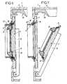
- the figure 1represents a sterile chamber 1 to which is connected to another sterile chamber 2 to allow the transfer of objects from the chamber 2 to the chamber 1, or vice versa.
- the enclosure 1is an enclosure in which work must be performed on sterile parts, for example the assembly of syringe components.
- the enclosure 2is itself an enclosure for the transfer of these sterile parts, before or after the completion of said work. In the example shown in the drawing, this chamber 2 is for single use, as will appear below.
- Each enclosure 1, 2comprises walls, respectively 3, 4 which delimit its interior volume, a circular flange, respectively 5, 6, and an access door, respectively 7, 8.
- the flanges 5, 6form the reception frames doors 7, 8 with sealing, and are adapted to be connected to each other for the communication of the speakers 1 and 2, after which the doors 7, 8 are open.
- the flange 5 of the chamber 1has a radially inwardly projecting circular rim 10 which forms sealing surfaces against which a circular seal 11 mounted on the door 7 tightly engages in the closed position of this door 7.
- the flange 5also has fingers 12 projecting from its outer face to the chamber 1, allowing the positioning of the flange 6 relative thereto.
- the door 7comprises an annular rib 13 for mounting the gasket 11 and a central boss 14 protruding axially from its outer face.
- This door 7is also connected to an arm 15 pivotally mounted on one of the walls 3.
- This arm 15allows the pivoting of the door 7 between the closed position shown in FIG. figure 1 and a position of complete opening, in which this door 7 is folded against one of the walls 3.
- the enclosure 1also comprises a protection device 20 formed by an annular part 21 and an arm 22 for supporting this part 21.
- the part 21comprises a portion 25 of frustoconical shape and a portion 26 of circular shape.
- the figure 8shows that the portion 25 is dimensioned so that, when the door 7 is in the open position, be engaged through the seat defined by the flange 5, so as to cover the areas of the flange 5 forming the seat, until beyond the outer face of the flange 10 and the seal 50 that includes the flange 6, and without contact with these areas.
- the wall of the portion 25is adapted to cover, when engaged in the openings defined by the seats of the doors (7,8) of the speakers (1,2) the connecting interface of these seats, without contact with this interface and with the surrounding areas, that is to say the areas of the flange 5 forming the seat of the door 7 to beyond the outer face of the flange 10 and the seal 50 that includes the flange 6 .
- the circular portion 26is in turn shaped so as to bear against the face of the flange 5 facing the inside of the chamber 1 in order to position the portion 25 axially relative to the flange 5 in this overlapping position. without touching.
- the arm 22is pivotally mounted on one of the walls 3 of the enclosure 1 and allows the movement of the part 21 between this non-contact covering position and an erasing position shown on the figure 1 , in which the device 20 is folded against one of the walls 3 and does not interfere with the work inside the enclosure 1.
- the enclosure 1further comprises locking assemblies 30 of the door 7 in the closed position, one of which is visible on the Figures 4 and 5 .
- each assembly 30comprises a shaft 31 mounted free to rotate in a bore passing through the flange 5, a latch 32 fixed on one end of the shaft 31 protruding into the enclosure 1, and a lever 33 wedged on the other end of the shaft 31, which protrudes outside the enclosure 1.
- the latch 32has the shape of a pallet and can occupy either an angular position in which it plates the door 7 against the flange 5 or an angular position in which it is located radially outside this door 7 to allow movements thereof.
- the shaft 31also comprises, on the outside of the flange 5, as visible on the figure 5 a latch 34 also in the form of a pallet and two radial fingers 35, 36 wedged on it.
- the latch 34can occupy either an angular position in which it plates the flange 6 against the flange 5, or an angular position in which it is located radially outside this flange 6 to allow the introduction or removal of this one with respect to the flange 5.
- the figure 5shows that the latch 34 is angularly offset relative to the latch 32 so that the latch 34 is erased when the latch 32 holds the door 7 against the flange 5 and that the latch 34 bears against the flange 6 before the latch 32 release the door 7.
- the radial fingers 35, 36are also angularly offset and make it possible to actuate pins 40, 41, 42 described below, to unlock / lock the door 8.
- the walls 4are made in the form of a bag made of a flexible and waterproof plastic material.
- the flange 6has a tubular skirt 45 for its sealed connection to said bag, a wall 46 projecting radially outwardly, intended to come into application against the flange 5 and to cooperate with the latch 34, and an intermediate zone 47 forming the reception seat of the door 8.
- the skirt 45has a groove made from its outer face, receiving a strapping 48 which provides the sealed connection of said bag to it.
- the wall 46includes notches 49 arranged from its outer edge, intended to receive the fingers 12 when the flange 6 is brought into contact with the flange 5 for the connection of the chamber 2 to the enclosure 1. These fingers 12 and notches 49 and form means for positioning the flanges 6, 5 relative to each other.
- the intermediate zone 47forms, as shown by figure 2 , a groove for receiving a seal 50 sealing between this flange 6 and the door 8.
- This seal 50has a mounting portion 51 engaged in this groove, a front portion 52 projecting slightly beyond the face axial end of the flange 6, and the bearing surfaces 53 for receiving the peripheral zone 8a of the door 8.
- the flange 6comprises two radial bores 55, 56 arranged so that they are directly above the fingers 35 and 36 when the flange 6 is in contact with the flange 5, as shown in FIG. figure 4 .
- the door 8comprises a recess 60 arranged from its outer face, dimensioned so as to be able to closely receive the boss 14 of the door 7, and has a peripheral rib 61 forming an edge, intended to come close against the seal 11 when the speakers 1 and 2 are connected to each other.
- This door 8further comprises two blind radial bores 65, 66 of the same diameter as the bores 55 and 56, coming when this door 8 is in the closed position shown on the Figures 4 and 5 respectively in front of these bores 55 and 56.
- the locking pins 40, 41, 42 mentioned aboveare engaged closely in the bores 55, 56, 65, 66 but with the possibility of sliding therein.
- the pin 40is partially engaged in the bore 55 so that its radially inner end is flush with the inner radial face of the flange 6. It has a length such that its protruding portion of the flange 6 is, when the flanges 6 and 5 are contiguous, on the angular displacement stroke of the finger 35 and can be pushed in the radially inner direction of the flange 6 by this finger 35 during this trip.
- the pin 41is engaged partially in the bore 56. It has a length such that, when the flanges 6 and 5 are contiguous, its portion protruding from the flange 6 is on the angular displacement stroke of the finger 36 and can be pushed in the radially inner direction of the flange 6 by this finger 36 to during this trip; the length of this pin 41 is furthermore equal to the length of the bore 56.
- the pin 42is partially engaged in the bore 56, following the pin 41, and in the bore 66. It thus holds the door 8 in position closure.
- the flanges 5 and 6are contiguous and positioned relative to each other by engagement of the flange 6 on the fingers 12 and the boss 14 in the cavity 60.
- the doors 7 and 8are then connected to each other. the other by appropriate means such as magnetic means and / or the practice of a vacuum between the doors
- the levers 33are then actuated clockwise appearing on the figure 5 so as to engage the latch 34 behind the wall 46 and to release the latch 32 from behind the door 7. Simultaneously, the finger 36 presses the pin 41 so as to fully engage the latter in the bore 56, which forces the pin 42 in the bore 66 and releases the door 8.
- the arm 15can then pivot to bring the door 7, and the door 8 connected to it, in the open position, as shown in FIG. figure 7 .
- the device 20is then rotated from its erasure position shown on the Figures 6 and 7 at its aforementioned non-contact covering position, shown on the figure 8 .
- the portion 26 of the part 21comes to rest against the inner face of the flange 5 and the portion 25 comes to cover the junction interface of the flanges 5 and 6, in particular the flange 10 and the seal 50.
- the objects or components contained in one enclosurecan then be transferred to the other enclosure without risk of contact or movement, even very light, of the seal 50, and therefore without risk of communication of the atmosphere of the speakers 1, 2 with the contaminated area isolated by this joint 50.
- the device 20is brought into the erasing position and then the doors 7 and 8 are brought into contact with their respective seats, after which the levers 33 are pivoted in the counterclockwise direction appearing on the figure 5 , which ensures the blocking of the door 7 by the latch 32 and the release of the flange 6 by the latch 34.
- the finger 35comes to bear against the pin 40, which it pushes completely into the bore 55, and thus in the bore 65, which ensures the 8.
- the flange 6is then separated from the flange 5 so as to extract the boss 14 from the cavity 60.
- the inventionprovides a significant improvement to the prior art, by providing a protective device 20 to eliminate any risk of contamination of an enclosure 1 by the other enclosure 2 as a result communicating these speakers with each other.
Landscapes
- Engineering & Computer Science (AREA)
- General Engineering & Computer Science (AREA)
- High Energy & Nuclear Physics (AREA)
- Physics & Mathematics (AREA)
- Health & Medical Sciences (AREA)
- Clinical Laboratory Science (AREA)
- Chemical & Material Sciences (AREA)
- Chemical Kinetics & Catalysis (AREA)
- Casings For Electric Apparatus (AREA)
- Electrical Discharge Machining, Electrochemical Machining, And Combined Machining (AREA)
- Closures For Containers (AREA)
- Physical Deposition Of Substances That Are Components Of Semiconductor Devices (AREA)
- Sealing Devices (AREA)
- Professional, Industrial, Or Sporting Protective Garments (AREA)
- Vacuum Packaging (AREA)
- Emergency Alarm Devices (AREA)
- Measuring Pulse, Heart Rate, Blood Pressure Or Blood Flow (AREA)
- Infusion, Injection, And Reservoir Apparatuses (AREA)
- Medical Preparation Storing Or Oral Administration Devices (AREA)
- Devices For Use In Laboratory Experiments (AREA)
- Sampling And Sample Adjustment (AREA)
Abstract
Description
Translated fromFrenchLa présente invention concerne un dispositif de protection pour une enceinte stérile susceptible d'être mise en communication avec une autre enceinte stérile afin de permettre le transfert d'objets d'une enceinte à l'autre.The present invention relates to a protection device for a sterile enclosure that can be placed in communication with another sterile enclosure to allow the transfer of objects from one enclosure to another.
Pour distinguer ces deux enceintes, la première enceinte citée sera dénommée ci-après "première enceinte" tandis que la deuxième enceinte citée sera dénommée "deuxième enceinte".To distinguish these two speakers, the first speaker cited will be referred to hereinafter as "first speaker" while the second speaker cited will be called "second speaker".
La première enceinte peut notamment être une enceinte dans laquelle un travail doit être réalisé sur des pièces stériles, et la deuxième enceinte peut notamment être une enceinte permettant le transfert de ces pièces stériles, avant ou après l'accomplissement dudit travail.The first chamber may in particular be an enclosure in which work must be performed on sterile parts, and the second chamber may in particular be an enclosure for the transfer of these sterile parts, before or after the completion of said work.
L'invention trouve une application particulièrement intéressante dans le cas des enceintes utilisées pour assembler des composants de seringues. La première enceinte est celle dans laquelle cet assemblage est réalisé, et la deuxième enceinte comprend généralement un sac souple en matière plastique, de réception des composants ou ensembles de composants à transférer.The invention finds a particularly interesting application in the case of enclosures used to assemble syringe components. The first enclosure is the one in which this assembly is made, and the second enclosure generally comprises a flexible plastic bag for receiving components or sets of components to be transferred.
Pour leur mise en communication l'une avec l'autre, ces enceintes comprennent des brides de raccordement étanche d'une enceinte à l'autre et sont équipées de portes d'accès, reçues avec étanchéité dans ces brides.For their communication with each other, these enclosures include flanges for sealing connection from one chamber to another and are equipped with access doors, received sealed in these flanges.
Sur un type d'enceintes existantes, décrites dans les documents
Ces enceintes existantes donnent satisfaction en pratique, mais il a pu être constaté qu'elles laissent subsister certains risques résiduels de contamination de l'enceinte de travail.These existing enclosures are satisfactory in practice, but it has been found that they leave some residual risk of contamination of the work area.
La présente invention vise à remédier à cet inconvénient essentiel, en fournissant un dispositif de protection propre à éliminer tout risque de contamination d'une première enceinte par une deuxième enceinte à la suite de la mise en communication de ces enceintes l'une avec l'autre.The present invention aims to overcome this essential disadvantage, by providing a protective device capable of eliminating any risk of contamination of a first enclosure by a second enclosure as a result of placing these speakers in communication with each other. other.
La présente invention se rapporte à un dispositif de protection pour une enceinte stérile susceptible d'être mise en communication avec une autre enceinte stérile, selon la revendication 1.The present invention relates to a protective device for a sterile enclosure that can be placed in communication with another sterile enclosure, according to
Cette pièce de protection est contenue dans l'une des enceintes et est placée dans cette position de recouvrement sans contact immédiatement après l'ouverture des portes des enceintes. Elle permet d'empêcher toute venue en contact des objets à transférer, des emballages de ces objets et/ou des gants ou des vêtements de l'opérateur avec le joint d'étanchéité se trouvant à l'interface de raccordement des sièges des portes.This protection piece is contained in one of the speakers and is placed in this non-contact covering position immediately after opening the speaker doors. It makes it possible to prevent the objects to be transferred, the packaging of these objects and / or the operator's gloves or clothing from coming into contact with the gasket located at the interface connecting the seats of the doors.
Il existe en effet le risque que ce joint soit touché ou déplacé, même très légèrement, par lesdits objets, emballages, gants ou vêtements lorsque ceux-ci sont transférés d'une enceinte à l'autre. Un tel contact ou déplacement conduit, s'il se produit, à rompre l'intégrité du contact de ce joint avec les surfaces contre lesquelles ce joint est appliqué, et donc à mettre un espace contaminé en communication avec l'atmosphère des enceintes.There is indeed the risk that this seal is touched or moved, even very slightly, by said objects, packaging, gloves or clothing when they are transferred from one enclosure to another. Such contact or displacement leads, if it occurs, to break the integrity of the contact of this seal with the surfaces against which this seal is applied, and thus to put a contaminated space in communication with the atmosphere of the speakers.
L'invention permet ainsi d'éliminer complètement ce risque de contact ou de déplacement et solutionne par conséquent les risques de contamination résiduels que présentent les enceintes selon la technique antérieure.The invention thus completely eliminates this risk of contact or displacement and therefore solves the risk of residual contamination that present the speakers according to the prior art.
De préférence, lesdits moyens de positionnement sont constitués par une ou plusieurs zones de la pièce de protection, conformées pour prendre appui contre la pièce délimitant le siège de l'une des portes, en des emplacements stériles de celle-ci.Preferably, said positioning means are constituted by one or more zones of the protective part, shaped to take support against the room delimiting the seat of one of the doors, in sterile locations thereof.
Ce positionnement est ainsi réalisé de manière particulièrement simple, notamment par une seule main de l'opérateur.This positioning is thus achieved in a particularly simple manner, in particular by one hand of the operator.
Selon une forme de réalisation préférée de l'invention, le dispositif de protection comprend au moins un bras de support de la pièce de protection, relié d'une part à cette pièce de protection et d'autre part à l'une des parois d'une enceinte, ce bras permettant le déplacement de la pièce de protection entre ladite position de recouvrement sans contact et une position d'effacement.According to a preferred embodiment of the invention, the protection device comprises at least one support arm of the protection piece, connected on the one hand to this protection piece and on the other hand to one of the walls of the protective part. an enclosure, this arm allowing the displacement of the protective part between said non-contact covering position and an erasure position.
La pièce de protection peut ainsi être facilement déplacée entre ses positions de recouvrement sans contact et d'effacement, et, dans cette position d'effacement, ne gêne pas le travail opéré dans l'enceinte.The protective member can thus be easily moved between its non-contact and erasing covering positions, and in this erasure position, does not interfere with the work performed in the enclosure.
Le bras de support peut notamment être monté pivotant sur la paroi de l'enceinte à laquelle il est relié.The support arm may in particular be pivotally mounted on the wall of the enclosure to which it is connected.
Avantageusement, le dispositif de protection comprend des moyens permettant d'immobiliser la pièce de protection dans ladite position de recouvrement sans contact, de sorte que tout risque de déplacement de cette pièce lors du transfert des objets est éliminé.Advantageously, the protection device comprises means for immobilizing the protective piece in said non-contact covering position, so that any risk of displacement of this part during the transfer of objects is eliminated.
Ces moyens d'immobilisation peuvent par exemple comprendre au moins un verrou, ou, si le dispositif comprend un bras pivotant tel que précité, des moyens de blocage ou de serrage agissant entre ce bras et l'axe de pivotement ou entre cet axe et la console assurant le montage de cet axe sur la paroi correspondante de l'enceinte.These immobilizing means may for example comprise at least one lock, or, if the device comprises a pivoting arm as mentioned above, locking or clamping means acting between this arm and the pivot axis or between this axis and the console ensuring the mounting of this axis on the corresponding wall of the enclosure.
Pour sa bonne compréhension, l'invention est à nouveau décrite ci-dessous en référence au dessin schématique annexé représentant, à titre d'exemple non limitatif, une forme de réalisation préférée du dispositif de protection qu'elle concerne.
- La
figure 1 est une vue en coupe longitudinale de deux enceintes stériles destinées à être raccordées l'une à l'autre ; chaque enceinte comprend à cet effet une porte qui la ferme normalement, une bride formant le dormant de cette porte et un joint placé entre cette porte et cette bride ; - la
figure 2 est une vue en coupe longitudinale et à échelle agrandie d'une portion d'un bord périphérique de la porte qui ferme l'une de ces enceintes, de la bride correspondante et du joint placé entre cette porte et cette bride ; - la
figure 3 est une vue similaire à lafigure 2 d'une portion du bord périphérique de la porte, de la bride et du joint qui assurent la fermeture de l'autre enceinte ; - la
figure 4 est une vue partielle, en coupe selon la ligne IV-IV de lafigure 5 et à échelle agrandie, d'un ensemble de verrouillage des brides l'une à l'autre et d'organes de verrouillage de chaque porte sur la bride correspondante ; - la
figure 5 est une vue de cet ensemble de verrouillage et de ces organes en coupe selon la ligne V-V de lafigure 4 ; - la
figure 6 est une vue partielle des enceintes, similaire à lafigure 1 , après raccordement de ces enceintes et avant ouverture des portes ; - la
figure 7 est une vue des enceintes similaire à lafigure 6 après ouverture des portes, et - la
figure 8 est une vue des enceintes similaire à lafigure 7 après mise en place au niveau de la zone de raccordement des brides d'un dispositif de protection que comprend l'une des enceintes.
- The
figure 1 is a longitudinal sectional view of two sterile enclosures intended to be connected to each other; each enclosure comprises for this purpose a door which closes normally, a flange forming the frame of this door and a seal placed between this door and this flange; - the
figure 2 is a longitudinal sectional view on an enlarged scale of a portion of a peripheral edge of the door which closes one of these enclosures, the corresponding flange and the seal placed between this door and this flange; - the
figure 3 is a view similar to thefigure 2 a portion of the peripheral edge of the door, the flange and the seal which ensure the closure of the other enclosure; - the
figure 4 is a partial view, in section along the line IV-IV of thefigure 5 and on an enlarged scale, a set of locking flanges to each other and locking members of each door on the corresponding flange; - the
figure 5 is a view of this locking assembly and these members in section along the line VV of thefigure 4 ; - the
figure 6 is a partial view of the speakers, similar to thefigure 1 , after connecting these speakers and before opening the doors; - the
figure 7 is a view of the speakers similar to thefigure 6 after opening the doors, and - the
figure 8 is a view of the speakers similar to thefigure 7 after installation at the flange connection area of a protective device that includes one of the speakers.
La
L'enceinte 1 est une enceinte dans laquelle un travail doit être réalisé sur des pièces stériles, par exemple l'assemblage de composants de seringues. L'enceinte 2 est quant à elle une enceinte permettant le transfert de ces pièces stériles, avant ou après l'accomplissement dudit travail. Dans l'exemple représenté au dessin, cette enceinte 2 est à usage unique, ainsi que cela apparaîtra plus loin.The
Chaque enceinte 1, 2 comprend des parois, respectivement 3, 4 qui délimitent son volume intérieur, une bride circulaire, respectivement 5, 6, et une porte d'accès, respectivement 7, 8. Les brides 5, 6 forment les dormants de réception des portes 7, 8 avec étanchéité, et sont propres à être raccordées l'une à l'autre pour la mise en communication des enceintes 1 et 2, après quoi les portes 7, 8 sont ouvertes.Each
Comme le montre plus précisément la
La bride 5 comporte également des doigts 12 faisant saillie de sa face extérieure à l'enceinte 1, permettant le positionnement de la bride 6 par rapport à elle.The
La porte 7 comprend une nervure annulaire 13 de montage du joint 11 et un bossage central 14 faisant saillie axialement de sa face extérieure.The door 7 comprises an
Cette porte 7 est en outre reliée à un bras 15 monté pivotant sur l'une des parois 3. Ce bras 15 permet le pivotement de la porte 7 entre la position de fermeture représentée sur la
L'enceinte 1 comprend également un dispositif de protection 20 formé par une pièce annulaire 21 et un bras 22 de support de cette pièce 21.The
La pièce 21 comprend une portion 25 de forme tronconique et une portion 26 de forme circulaire.The
La
Ainsi, la paroi de la portion 25 est propre à recouvrir, lorsqu'elle est engagée dans les ouvertures délimitées par les sièges des portes (7,8) des enceintes (1,2) l'interface de raccordement de ces sièges, sans contact avec cette interface ni avec les zones environnantes, c'est-à-dire les zones de la bride 5 formant le siège de la porte 7 jusqu'au-delà de la face extérieure du rebord 10 et du joint 50 que comprend la bride 6.Thus, the wall of the
La portion circulaire 26 est quant à elle conformée de manière à venir en appui contre la face de la bride 5 tournée vers l'intérieur de l'enceinte 1 afin de positionner axialement la portion 25 par rapport à la bride 5 dans cette position de recouvrement sans contact.The
Le bras 22 est monté pivotant sur l'une des parois 3 de l'enceinte 1 et permet le déplacement de la pièce 21 entre cette position de recouvrement sans contact et une position d'effacement montrée sur la
L'enceinte 1 comprend en outre des ensembles 30 de verrouillage de la porte 7 en position de fermeture, dont un est visible sur les
En référence à ces figures, chaque ensemble 30 comprend un arbre 31 monté libre en rotation dans un alésage traversant la bride 5, un verrou 32 calé sur une extrémité de l'arbre 31 dépassant dans l'enceinte 1, et un levier 33 calé sur l'autre extrémité de l'arbre 31, qui dépasse à l'extérieur de l'enceinte 1. Le verrou 32 présente la forme d'une palette et peut occuper soit une position angulaire dans laquelle il plaque la porte 7 contre la bride 5, soit une position angulaire dans laquelle il est situé radialement à l'extérieur de cette porte 7 pour autoriser les mouvements de celle-ci.With reference to these figures, each
L'arbre 31 comporte également, sur l'extérieur de la bride 5, comme visible sur la
Les doigts radiaux 35, 36 sont également décalés angulairement et permettent d'actionner des pions 40, 41, 42 décrits plus loin, de déverrouillage/verrouillage de la porte 8.The
S'agissant de l'enceinte 2, les parois 4 sont réalisées sous la forme d'un sac en une matière plastique souple et étanche.As regards the enclosure 2, the
La bride 6 présente une jupe tubulaire 45 pour sa jonction étanche audit sac, une paroi 46 faisant saillie radialement vers l'extérieur, destinée à venir en application contre la bride 5 et à coopérer avec le verrou 34, et une zone intermédiaire 47 formant le siège de réception de la porte 8.The
La jupe 45 présente une gorge aménagée à partir de sa face extérieure, recevant un cerclage 48 qui assure la jonction étanche dudit sac à elle.The
La paroi 46 comprend des encoches 49 aménagées à partir de son bord extérieur, destinées à recevoir les doigts 12 lorsque la bride 6 est amenée au contact de la bride 5 en vue du raccordement de l'enceinte 2 à l'enceinte 1. Ces doigts 12 et encoches 49 forment ainsi des moyens de positionnement des brides 6, 5 l'une par rapport à l'autre.The
La zone intermédiaire 47 forme, ainsi que le montre la
En outre, comme le montrent les
La porte 8 comprend un embrèvement 60 aménagé à partir de sa face extérieure, dimensionné de manière à pouvoir recevoir étroitement le bossage 14 de la porte 7, et présente une nervure périphérique 61 formant une arête, destinée à venir porter étroitement contre le joint 11 lorsque les enceintes 1 et 2 sont raccordées l'une à l'autre.The
Cette porte 8 comprend en outre deux alésages radiaux borgnes 65, 66 de même diamètres que les alésages 55 et 56, venant, lorsque cette porte 8 est en position de fermeture montrée sur les
Les pions de verrouillage 40, 41, 42 précités sont engagés étroitement dans les alésages 55, 56, 65, 66 mais avec possibilité de coulissement dans ceux-ci.The locking pins 40, 41, 42 mentioned above are engaged closely in the
Ainsi que cela apparaît sur les
Egalement avant mise en connexion de l'enceinte 2 avec l'enceinte 1, le pion 41 est engagé partiellement dans l'alésage 56. Il a une longueur telle que, lorsque les brides 6 et 5 sont accolées, sa partie dépassant de la bride 6 se trouve sur la course de déplacement angulaire du doigt 36 et qu'il peut être poussé dans la direction radialement interne de la bride 6 par ce doigt 36 au cours de ce déplacement ; la longueur de ce pion 41 est en outre égale à la longueur de l'alésage 56.Also before connection of the chamber 2 with the
Egalement avant mise en connexion de l'enceinte 2 avec l'enceinte 1, le pion 42 est engagé partiellement dans l'alésage 56, à la suite du pion 41, et dans l'alésage 66. Il maintien ainsi la porte 8 en position de fermeture.Also before connection of the chamber 2 with the
En pratique, comme le montre la
Les leviers 33 sont alors actionnés dans le sens horaire apparaissant sur la
Le bras 15 peut alors pivoter pour amener la porte 7, et la porte 8 reliée à elle, en position d'ouverture, comme le montre la
Le dispositif 20 est ensuite pivoté de sa position d'effacement montrée sur les
Pour refermer et séparer les enceintes 1, 2, le dispositif 20 est amené en position d'effacement puis les portes 7 et 8 sont ramenées au contact de leur sièges respectifs, après quoi les leviers 33 sont pivotés dans le sens anti-horaire apparaissant sur la
Ainsi qu'il apparaît de ce qui précède, l'invention apporte une amélioration notable à la technique antérieure, en fournissant un dispositif de protection 20 propre à éliminer tout risque de contamination d'une enceinte 1 par l'autre enceinte 2 à la suite de la mise en communication de ces enceintes l'une avec l'autre.As it appears from the foregoing, the invention provides a significant improvement to the prior art, by providing a
Il va de soi que l'invention n'est pas limitée à la forme de réalisation décrite ci-dessus à titre d'exemple mais qu'elle en embrasse au contraire toutes les variantes de réalisation entrant dans le champ de protection défini par les revendications ci-annexées.It goes without saying that the invention is not limited to the embodiment described above by way of example but that it embraces on the contrary all variants within the scope of protection defined by the claims appended.
Claims (8)
- A protective device (20) for protecting a sterile enclosure (1) likely to be placed in communication with another sterile enclosure (2) so as to allow sterile parts to be transferred from one enclosure to the other for the purpose of working on these parts, each enclosure (1,2) comprising a door (7,8), each door comprising a flange (5,6) forming a seat delimiting an opening, these seats having an interface where they meet,characterized in that it comprises:- a protective component (21) having a wall (25) capable, when engaged in the openings delimited by the seats of the doors (7, 8) of the enclosures (1, 2), of covering the interface where these two seats meet, without contact with this interface or with the surrounding regions, that is to say the regions of the flange (5) forming the seat of the door (7) as far as beyond the exterior face of a rim (10) and of a seal (50) that the flange (6) has, and- positioning means (26) allowing this wall (25) to be positioned with respect to this interface in this contactless covering position.
- The protective device (20) as claimed in claim 1,characterized in that, the seat of one of the doors (7) being delimited by a component (5), said positioning means consist of one or more regions (26) of the protective component (21), which are shaped to bear against the component (5) delimiting the seat of one of the doors (7), at sterile locations thereof.
- The protective device (20) as claimed in claim 1 or claim 2,characterized in that it comprises at least one arm (22) for supporting the protective component (21), which arm is connected on the one hand to this protective component (21) and on the other hand to one of the walls (3) of an enclosure (1), this arm (22) allowing the protective component (21) to be moved between said contactless covering position and a retracted position.
- The protective device (20) as claimed in claim 3,characterized in that the support arm (22) is mounted so that it can pivot on the wall (3) of the enclosure (1) to which it is connected.
- The protective device (20) as claimed in one of claims 1 to 4,characterized in that it comprises means allowing the protective component (21) to be immobilized in said contactless covering position.
- The protective device (20) as claimed in claim 5,characterized in that the means of immobilizing the protective component (21) in said contactless covering position comprise at least one latch.
- The protective device (20) as claimed in claim 5,characterized in that the means of immobilizing the protective component (21) in said contactless covering position comprise blocking or clamping means acting between the arm (22) supporting the protective component (21) and the axle about which this arm (22) pivots or between this axle and the bracket used for mounting this axle on the corresponding wall (3) of the enclosure (1).
- A sterile enclosure (1) likely to be placed in communication with another sterile enclosure (2) so as to allow objects to be transferred from one enclosure to the other,characterized in that it comprises the protective device (20) as claimed in one of claims 1 to 7.
Applications Claiming Priority (3)
| Application Number | Priority Date | Filing Date | Title |
|---|---|---|---|
| FR0116254 | 2001-12-14 | ||
| FR0116254AFR2833745B1 (en) | 2001-12-14 | 2001-12-14 | PROTECTION DEVICE FOR STERILE SPEAKER |
| PCT/FR2002/004357WO2003053784A2 (en) | 2001-12-14 | 2002-12-13 | Protective device for sterile chamber |
Publications (2)
| Publication Number | Publication Date |
|---|---|
| EP1454328A2 EP1454328A2 (en) | 2004-09-08 |
| EP1454328B1true EP1454328B1 (en) | 2010-02-17 |
Family
ID=8870542
Family Applications (1)
| Application Number | Title | Priority Date | Filing Date |
|---|---|---|---|
| EP02805389AExpired - LifetimeEP1454328B1 (en) | 2001-12-14 | 2002-12-13 | Protective device for sterile chamber |
Country Status (9)
| Country | Link |
|---|---|
| US (1) | US9314787B2 (en) |
| EP (1) | EP1454328B1 (en) |
| JP (1) | JP5009489B2 (en) |
| AT (1) | ATE458252T1 (en) |
| AU (1) | AU2002366750A1 (en) |
| DE (1) | DE60235397D1 (en) |
| ES (1) | ES2339928T3 (en) |
| FR (1) | FR2833745B1 (en) |
| WO (1) | WO2003053784A2 (en) |
Cited By (2)
| Publication number | Priority date | Publication date | Assignee | Title |
|---|---|---|---|---|
| US9168520B2 (en) | 2009-11-23 | 2015-10-27 | Sartorius Stedim Aseptics | Chamber for sealed junction device and aseptic transfer device |
| US9283556B2 (en) | 2009-11-23 | 2016-03-15 | Sartorius Stedim Aseptics | Tight connection and tight transfer between two housings in view of an aseptic transfer therebetween |
Families Citing this family (18)
| Publication number | Priority date | Publication date | Assignee | Title |
|---|---|---|---|---|
| FR2872446A1 (en)* | 2004-07-02 | 2006-01-06 | Commissariat Energie Atomique | Sealed double-door transfer system e.g. for confinement chamber has doors fitted with internal actuators and peepholes for viewing |
| JP2007137477A (en)* | 2005-11-18 | 2007-06-07 | Chiyoda Maintenance Kk | Device to store item in airtight container |
| FR3010120B1 (en)* | 2013-09-03 | 2016-03-04 | Getinge La Calhene | SEALED CONNECTION DEVICE BETWEEN TWO CLOSED VOLUMES COMPRISING MEANS FOR MAINTAINING BEFORE THE CONNECTION |
| FR3010119A1 (en)* | 2013-09-03 | 2015-03-06 | Getinge La Calhene | SAFELY CONNECTED CONNECTION DEVICE FOR IMPROVED OPERATION |
| FR3010118B1 (en) | 2013-09-03 | 2016-02-26 | Getinge La Calhene | SEALED SPEAKER HAVING AN OPENING AND CLOSING CONTROL MECHANISM FOR A SEALED CONNECTION DEVICE BETWEEN TWO CLOSED VOLUMES |
| GB2542123A (en)* | 2015-09-08 | 2017-03-15 | Chargepoint Tech Ltd | Transfer device |
| FR3046206B1 (en)* | 2015-12-23 | 2018-01-12 | Sartorius Stedim Aseptics | METHOD FOR MANUFACTURING A SEALED CONTAINER |
| JP6772596B2 (en)* | 2016-06-30 | 2020-10-21 | 澁谷工業株式会社 | Isolator |
| US10926305B2 (en)* | 2017-08-02 | 2021-02-23 | Marc Cordes | Methods and systems for decontaminating harmful material |
| KR20200091919A (en) | 2017-12-11 | 2020-07-31 | 글락소스미스클라인 인털렉츄얼 프로퍼티 디벨로프먼트 리미티드 | Modular aseptic production system |
| JP6975373B2 (en)* | 2017-12-27 | 2021-12-01 | 澁谷工業株式会社 | Aseptic work system |
| FR3082126B1 (en)* | 2018-06-11 | 2022-10-28 | Getinge La Calhene | TRANSFER SYSTEM FOR WATERPROOF ENCLOSURE COMPRISING A WATERPROOF CONNECTION DEVICE WITH A CLOSED VOLUME |
| FR3102698B1 (en)* | 2019-11-05 | 2023-03-03 | Abc Transfer | WATERPROOF CONTAINER COMPRISING A DEVICE FOR REMOVABLE CONNECTION TO A SPEAKER |
| FR3105186B1 (en)* | 2019-12-20 | 2021-11-12 | Abc Transfer | WATERPROOF CONTAINER INCLUDING A DEVICE ALLOWING REMOVABLE CONNECTION TO A SPEAKER |
| FR3105055B1 (en)* | 2019-12-20 | 2021-11-26 | Abc Tranfer | DOOR ARRANGEMENT EQUIPPING A FIRST CLOSED VOLUME TO REDUCE THE RISKS OF CONTAMINATION WHEN CONNECTING A SECOND CLOSED VOLUME TO THE FIRST CLOSED VOLUME |
| FR3105184B1 (en)* | 2019-12-20 | 2021-11-12 | Abc Transfer | REINFORCED WATERPROOF CONTAINER |
| FR3124414A1 (en)* | 2021-06-23 | 2022-12-30 | Jce Biotechnology | Installation for preparing a centrifuged product, as well as corresponding method of preparation using such an installation |
| KR102860037B1 (en)* | 2025-02-04 | 2025-09-15 | (주)씨에이치씨 바이오텍 | Glove box with double sealing structure |
Family Cites Families (14)
| Publication number | Priority date | Publication date | Assignee | Title |
|---|---|---|---|---|
| US2678252A (en)* | 1953-05-08 | 1954-05-11 | Oscar R Swearingen | Toilet cabinet |
| FR2625023B2 (en)* | 1978-03-09 | 1990-04-20 | Commissariat Energie Atomique | JOINING DEVICE BETWEEN A TRANSPORT CONTAINER AND A HORIZONTAL WALL OF A UNLOADING ENCLOSURE |
| FR2419568A1 (en)* | 1978-03-09 | 1979-10-05 | Commissariat Energie Atomique | JUNCTION DEVICE BETWEEN A CONTAINER AND A UNLOADING ENCLOSURE |
| US4260312A (en)* | 1978-09-27 | 1981-04-07 | United Kingdom Atomic Energy Authority | Apparatus for transferring toxic and radioactive materials |
| JPS5830930A (en)* | 1981-08-18 | 1983-02-23 | 大日本印刷株式会社 | Container feeding device for aseptic filling machine |
| DE3814938A1 (en)* | 1988-05-03 | 1989-11-16 | Wiederaufarbeitung Von Kernbre | DOCKING DEVICE FOR CONNECTING A TRANSPORT AND / OR STORAGE CONTAINER TO A RADIOACTIVELY LOADED WORK SPACE |
| FR2673990B1 (en)* | 1991-03-14 | 1993-07-16 | Sne Calhene | VALVE FORMING DEVICE FOR THE SEALED CONNECTION OF TWO CONTAINERS AND CONTAINER PROVIDED TO BE COUPLED TO SUCH A DEVICE. |
| FR2674225B1 (en)* | 1991-03-20 | 1993-07-16 | Euritech | PROCESS AND INSTALLATION FOR TRANSFERRING PRODUCTS FROM A CONTAMINATED ENCLOSURE TO A SECOND ENCLOSURE, WITHOUT CONTAMINATING THE LATTER. |
| US5447699A (en) | 1993-11-17 | 1995-09-05 | The West Company | Combination container for holding sterilized elements and a sterilizable transfer port |
| US5460439A (en)* | 1994-01-07 | 1995-10-24 | Delaware Capital Formation, Inc. | Sealed transfer system |
| FR2721289B1 (en)* | 1994-06-17 | 1996-08-30 | Idc Isolateur Denominateur | Sealed connection device between two enclosures isolated from an external environment. |
| US6779567B1 (en)* | 1998-07-10 | 2004-08-24 | La Calhene, Inc. | Rapid transfer port |
| FR2787235B1 (en) | 1998-12-11 | 2001-01-19 | Becton Dickinson France | DEVICE FOR CONNECTING DOORS BETWEEN TWO ENCLOSURES ISOLATED FROM THE EXTERNAL ENVIRONMENT |
| FR2787190B1 (en) | 1998-12-11 | 2001-02-16 | Becton Dickinson France | DEVICE FOR DETECTING THE SEALING OF THE CONNECTION BETWEEN THE ELEMENTS OF A DEVICE FOR SEALING TWO ISOLATED ENCLOSURES FROM THE EXTERNAL ENVIRONMENT |
- 2001
- 2001-12-14FRFR0116254Apatent/FR2833745B1/ennot_activeExpired - Fee Related
- 2002
- 2002-12-13ESES02805389Tpatent/ES2339928T3/ennot_activeExpired - Lifetime
- 2002-12-13ATAT02805389Tpatent/ATE458252T1/enactive
- 2002-12-13USUS10/497,952patent/US9314787B2/enactiveActive
- 2002-12-13DEDE60235397Tpatent/DE60235397D1/ennot_activeExpired - Lifetime
- 2002-12-13WOPCT/FR2002/004357patent/WO2003053784A2/enactiveApplication Filing
- 2002-12-13AUAU2002366750Apatent/AU2002366750A1/ennot_activeAbandoned
- 2002-12-13JPJP2003554515Apatent/JP5009489B2/ennot_activeExpired - Lifetime
- 2002-12-13EPEP02805389Apatent/EP1454328B1/ennot_activeExpired - Lifetime
Cited By (2)
| Publication number | Priority date | Publication date | Assignee | Title |
|---|---|---|---|---|
| US9168520B2 (en) | 2009-11-23 | 2015-10-27 | Sartorius Stedim Aseptics | Chamber for sealed junction device and aseptic transfer device |
| US9283556B2 (en) | 2009-11-23 | 2016-03-15 | Sartorius Stedim Aseptics | Tight connection and tight transfer between two housings in view of an aseptic transfer therebetween |
Also Published As
| Publication number | Publication date |
|---|---|
| WO2003053784A2 (en) | 2003-07-03 |
| US9314787B2 (en) | 2016-04-19 |
| AU2002366750A1 (en) | 2003-07-09 |
| DE60235397D1 (en) | 2010-04-01 |
| EP1454328A2 (en) | 2004-09-08 |
| AU2002366750A8 (en) | 2003-07-09 |
| WO2003053784A3 (en) | 2003-12-18 |
| FR2833745B1 (en) | 2004-10-01 |
| ES2339928T3 (en) | 2010-05-27 |
| JP2005517594A (en) | 2005-06-16 |
| JP5009489B2 (en) | 2012-08-22 |
| FR2833745A1 (en) | 2003-06-20 |
| ATE458252T1 (en) | 2010-03-15 |
| US20050168117A1 (en) | 2005-08-04 |
Similar Documents
| Publication | Publication Date | Title |
|---|---|---|
| EP1454328B1 (en) | Protective device for sterile chamber | |
| FR2981386A1 (en) | HIGH-LEVEL SAFETY CONTROL MECHANISM FOR A TRANSFER DEVICE SEALED BETWEEN TWO CLOSED VOLUMES | |
| FR2695343A1 (en) | Centralized control mechanism, with incorporated safety devices, for a sealed transfer device between two enclosed volumes. | |
| EP0505269B1 (en) | Method and installation for transferring products from a contaminated enclosure to a second enclosure without contaminating the latter | |
| EP3042380B1 (en) | Device providing fluidtight connection in two enclosed volumes comprising means of holding prior to connection | |
| WO2008049879A1 (en) | Radioactive waste storage container | |
| FR2949599A1 (en) | DOUBLE DOOR TEMPORARY SEALED JUNCTION DEVICE | |
| EP4351781B1 (en) | Sealed double-door connection device with reinforced security | |
| WO2012175506A1 (en) | System for sealingly attaching a mobile container onto a cell and for opening the container | |
| EP3230018B1 (en) | Transfer assembly | |
| FR2613526A1 (en) | Disconnectable device for placing two enclosed volumes in communication | |
| EP2946833B1 (en) | Device for watertight connection between two enclosures | |
| FR2781550A1 (en) | METHOD FOR CHANGING A FILTER CARTRIDGE MOUNTED IN A FLUID FLOW CONDUIT AND ARRANGEMENT FOR IMPLEMENTING THE METHOD | |
| FR2781186A1 (en) | DEVICE FOR SHUTTERING A HOUSING IN THE BODY OF A VEHICLE, WITH ROTATING HANDLE | |
| FR2877968A1 (en) | LOCK OF MOTOR VEHICLE | |
| CA3140657C (en) | Key gripper system | |
| FR2827521A1 (en) | Air bag component insertion procedure uses circular aperture with adjoining oblong extension and inner reinforcing layer | |
| WO2024156757A1 (en) | Improved cell flange for a sealed transfer system | |
| WO2024156758A1 (en) | Cell flange for a double sealed door with reduced opening forces | |
| FR2845645A1 (en) | Motor vehicle fuel tank filler has spring-loaded flap that is opened with light pressure and inner seal engaging with bowl surface | |
| FR2617717A1 (en) | Connection, injection or withdrawal device for medical use, comprising a protective casing and a connection site | |
| FR3145231A1 (en) | CONTAINER DOOR FOR WATERPROOF TRANSFER SYSTEM | |
| FR3133210A1 (en) | Actuating device suitable for different types of transmission element for door lock | |
| WO2025196131A1 (en) | Cell flange for a double airlock door with pressurizing channel | |
| FR2878196A1 (en) | Pivoting device for vehicle seat, has stop unit that cooperates with plate and is slidingly mounted with respect to plate for permitting adjustment of position of stop unit before immobilization of stop unit |
Legal Events
| Date | Code | Title | Description |
|---|---|---|---|
| PUAI | Public reference made under article 153(3) epc to a published international application that has entered the european phase | Free format text:ORIGINAL CODE: 0009012 | |
| 17P | Request for examination filed | Effective date:20040602 | |
| AK | Designated contracting states | Kind code of ref document:A2 Designated state(s):AT BE BG CH CY CZ DE DK EE ES FI FR GB GR IE IT LI LU MC NL PT SE SI SK TR | |
| AX | Request for extension of the european patent | Extension state:AL LT LV MK RO | |
| RAP1 | Party data changed (applicant data changed or rights of an application transferred) | Owner name:BECTON DICKINSON FRANCE | |
| 17Q | First examination report despatched | Effective date:20081121 | |
| GRAP | Despatch of communication of intention to grant a patent | Free format text:ORIGINAL CODE: EPIDOSNIGR1 | |
| GRAS | Grant fee paid | Free format text:ORIGINAL CODE: EPIDOSNIGR3 | |
| GRAA | (expected) grant | Free format text:ORIGINAL CODE: 0009210 | |
| AK | Designated contracting states | Kind code of ref document:B1 Designated state(s):AT BE BG CH CY CZ DE DK EE ES FI FR GB GR IE IT LI LU MC NL PT SE SI SK TR | |
| REG | Reference to a national code | Ref country code:GB Ref legal event code:FG4D Free format text:NOT ENGLISH | |
| REG | Reference to a national code | Ref country code:CH Ref legal event code:EP | |
| REG | Reference to a national code | Ref country code:IE Ref legal event code:FG4D Free format text:LANGUAGE OF EP DOCUMENT: FRENCH | |
| REG | Reference to a national code | Ref country code:CH Ref legal event code:NV Representative=s name:CABINET GERMAIN & MAUREAU | |
| REF | Corresponds to: | Ref document number:60235397 Country of ref document:DE Date of ref document:20100401 Kind code of ref document:P | |
| REG | Reference to a national code | Ref country code:SE Ref legal event code:TRGR | |
| REG | Reference to a national code | Ref country code:NL Ref legal event code:T3 | |
| REG | Reference to a national code | Ref country code:ES Ref legal event code:FG2A Ref document number:2339928 Country of ref document:ES Kind code of ref document:T3 | |
| PG25 | Lapsed in a contracting state [announced via postgrant information from national office to epo] | Ref country code:PT Free format text:LAPSE BECAUSE OF FAILURE TO SUBMIT A TRANSLATION OF THE DESCRIPTION OR TO PAY THE FEE WITHIN THE PRESCRIBED TIME-LIMIT Effective date:20100617 | |
| PG25 | Lapsed in a contracting state [announced via postgrant information from national office to epo] | Ref country code:SI Free format text:LAPSE BECAUSE OF FAILURE TO SUBMIT A TRANSLATION OF THE DESCRIPTION OR TO PAY THE FEE WITHIN THE PRESCRIBED TIME-LIMIT Effective date:20100217 Ref country code:FI Free format text:LAPSE BECAUSE OF FAILURE TO SUBMIT A TRANSLATION OF THE DESCRIPTION OR TO PAY THE FEE WITHIN THE PRESCRIBED TIME-LIMIT Effective date:20100217 | |
| REG | Reference to a national code | Ref country code:CH Ref legal event code:PFA Owner name:BECTON DICKINSON FRANCE Free format text:BECTON DICKINSON FRANCE#11, RUE ARISTIDE BERGES, B.P. 4#38800 LE PONT DE CLAIX (FR) -TRANSFER TO- BECTON DICKINSON FRANCE#11, RUE ARISTIDE BERGES, B.P. 4#38800 LE PONT DE CLAIX (FR) | |
| PG25 | Lapsed in a contracting state [announced via postgrant information from national office to epo] | Ref country code:GR Free format text:LAPSE BECAUSE OF FAILURE TO SUBMIT A TRANSLATION OF THE DESCRIPTION OR TO PAY THE FEE WITHIN THE PRESCRIBED TIME-LIMIT Effective date:20100518 Ref country code:EE Free format text:LAPSE BECAUSE OF FAILURE TO SUBMIT A TRANSLATION OF THE DESCRIPTION OR TO PAY THE FEE WITHIN THE PRESCRIBED TIME-LIMIT Effective date:20100217 Ref country code:CY Free format text:LAPSE BECAUSE OF FAILURE TO SUBMIT A TRANSLATION OF THE DESCRIPTION OR TO PAY THE FEE WITHIN THE PRESCRIBED TIME-LIMIT Effective date:20100217 | |
| PG25 | Lapsed in a contracting state [announced via postgrant information from national office to epo] | Ref country code:SK Free format text:LAPSE BECAUSE OF FAILURE TO SUBMIT A TRANSLATION OF THE DESCRIPTION OR TO PAY THE FEE WITHIN THE PRESCRIBED TIME-LIMIT Effective date:20100217 Ref country code:CZ Free format text:LAPSE BECAUSE OF FAILURE TO SUBMIT A TRANSLATION OF THE DESCRIPTION OR TO PAY THE FEE WITHIN THE PRESCRIBED TIME-LIMIT Effective date:20100217 Ref country code:BG Free format text:LAPSE BECAUSE OF FAILURE TO SUBMIT A TRANSLATION OF THE DESCRIPTION OR TO PAY THE FEE WITHIN THE PRESCRIBED TIME-LIMIT Effective date:20100517 | |
| PLBE | No opposition filed within time limit | Free format text:ORIGINAL CODE: 0009261 | |
| STAA | Information on the status of an ep patent application or granted ep patent | Free format text:STATUS: NO OPPOSITION FILED WITHIN TIME LIMIT | |
| 26N | No opposition filed | Effective date:20101118 | |
| PG25 | Lapsed in a contracting state [announced via postgrant information from national office to epo] | Ref country code:DK Free format text:LAPSE BECAUSE OF FAILURE TO SUBMIT A TRANSLATION OF THE DESCRIPTION OR TO PAY THE FEE WITHIN THE PRESCRIBED TIME-LIMIT Effective date:20100217 | |
| PG25 | Lapsed in a contracting state [announced via postgrant information from national office to epo] | Ref country code:MC Free format text:LAPSE BECAUSE OF NON-PAYMENT OF DUE FEES Effective date:20101231 | |
| PG25 | Lapsed in a contracting state [announced via postgrant information from national office to epo] | Ref country code:LU Free format text:LAPSE BECAUSE OF NON-PAYMENT OF DUE FEES Effective date:20101213 | |
| PG25 | Lapsed in a contracting state [announced via postgrant information from national office to epo] | Ref country code:TR Free format text:LAPSE BECAUSE OF FAILURE TO SUBMIT A TRANSLATION OF THE DESCRIPTION OR TO PAY THE FEE WITHIN THE PRESCRIBED TIME-LIMIT Effective date:20100217 | |
| REG | Reference to a national code | Ref country code:CH Ref legal event code:PCAR Free format text:NEW ADDRESS: RUE DU RHONE 14, 1204 GENEVE (CH) | |
| REG | Reference to a national code | Ref country code:FR Ref legal event code:PLFP Year of fee payment:14 | |
| REG | Reference to a national code | Ref country code:FR Ref legal event code:PLFP Year of fee payment:15 | |
| REG | Reference to a national code | Ref country code:FR Ref legal event code:PLFP Year of fee payment:16 | |
| PGFP | Annual fee paid to national office [announced via postgrant information from national office to epo] | Ref country code:SE Payment date:20211119 Year of fee payment:20 Ref country code:DE Payment date:20211117 Year of fee payment:20 Ref country code:AT Payment date:20211118 Year of fee payment:20 Ref country code:FR Payment date:20211118 Year of fee payment:20 Ref country code:NL Payment date:20211118 Year of fee payment:20 Ref country code:IE Payment date:20211118 Year of fee payment:20 Ref country code:GB Payment date:20211118 Year of fee payment:20 | |
| PGFP | Annual fee paid to national office [announced via postgrant information from national office to epo] | Ref country code:IT Payment date:20211117 Year of fee payment:20 Ref country code:CH Payment date:20211119 Year of fee payment:20 Ref country code:BE Payment date:20211122 Year of fee payment:20 | |
| PGFP | Annual fee paid to national office [announced via postgrant information from national office to epo] | Ref country code:ES Payment date:20220103 Year of fee payment:20 | |
| REG | Reference to a national code | Ref country code:DE Ref legal event code:R071 Ref document number:60235397 Country of ref document:DE | |
| REG | Reference to a national code | Ref country code:NL Ref legal event code:MK Effective date:20221212 | |
| REG | Reference to a national code | Ref country code:CH Ref legal event code:PL | |
| REG | Reference to a national code | Ref country code:BE Ref legal event code:MK Effective date:20221213 Ref country code:GB Ref legal event code:PE20 Expiry date:20221212 | |
| PG25 | Lapsed in a contracting state [announced via postgrant information from national office to epo] | Ref country code:GB Free format text:LAPSE BECAUSE OF EXPIRATION OF PROTECTION Effective date:20221212 | |
| REG | Reference to a national code | Ref country code:SE Ref legal event code:EUG | |
| REG | Reference to a national code | Ref country code:IE Ref legal event code:MK9A | |
| REG | Reference to a national code | Ref country code:AT Ref legal event code:MK07 Ref document number:458252 Country of ref document:AT Kind code of ref document:T Effective date:20221213 | |
| PG25 | Lapsed in a contracting state [announced via postgrant information from national office to epo] | Ref country code:IE Free format text:LAPSE BECAUSE OF EXPIRATION OF PROTECTION Effective date:20221213 | |
| REG | Reference to a national code | Ref country code:ES Ref legal event code:FD2A Effective date:20230428 | |
| PG25 | Lapsed in a contracting state [announced via postgrant information from national office to epo] | Ref country code:ES Free format text:LAPSE BECAUSE OF EXPIRATION OF PROTECTION Effective date:20221214 |