EP1452753B1 - Roller bearing with integrated sensor - Google Patents
Roller bearing with integrated sensorDownload PDFInfo
- Publication number
- EP1452753B1 EP1452753B1EP04290379AEP04290379AEP1452753B1EP 1452753 B1EP1452753 B1EP 1452753B1EP 04290379 AEP04290379 AEP 04290379AEP 04290379 AEP04290379 AEP 04290379AEP 1452753 B1EP1452753 B1EP 1452753B1
- Authority
- EP
- European Patent Office
- Prior art keywords
- elastic member
- rotating
- assembly
- bearing
- sensor assembly
- Prior art date
- Legal status (The legal status is an assumption and is not a legal conclusion. Google has not performed a legal analysis and makes no representation as to the accuracy of the status listed.)
- Expired - Lifetime
Links
Images


Classifications
- F—MECHANICAL ENGINEERING; LIGHTING; HEATING; WEAPONS; BLASTING
- F16—ENGINEERING ELEMENTS AND UNITS; GENERAL MEASURES FOR PRODUCING AND MAINTAINING EFFECTIVE FUNCTIONING OF MACHINES OR INSTALLATIONS; THERMAL INSULATION IN GENERAL
- F16C—SHAFTS; FLEXIBLE SHAFTS; ELEMENTS OR CRANKSHAFT MECHANISMS; ROTARY BODIES OTHER THAN GEARING ELEMENTS; BEARINGS
- F16C41/00—Other accessories, e.g. devices integrated in the bearing not relating to the bearing function as such
- F16C41/007—Encoders, e.g. parts with a plurality of alternating magnetic poles
- F—MECHANICAL ENGINEERING; LIGHTING; HEATING; WEAPONS; BLASTING
- F16—ENGINEERING ELEMENTS AND UNITS; GENERAL MEASURES FOR PRODUCING AND MAINTAINING EFFECTIVE FUNCTIONING OF MACHINES OR INSTALLATIONS; THERMAL INSULATION IN GENERAL
- F16C—SHAFTS; FLEXIBLE SHAFTS; ELEMENTS OR CRANKSHAFT MECHANISMS; ROTARY BODIES OTHER THAN GEARING ELEMENTS; BEARINGS
- F16C25/00—Bearings for exclusively rotary movement adjustable for wear or play
- F16C25/06—Ball or roller bearings
- F16C25/08—Ball or roller bearings self-adjusting
- F16C25/083—Ball or roller bearings self-adjusting with resilient means acting axially on a race ring to preload the bearing
- F—MECHANICAL ENGINEERING; LIGHTING; HEATING; WEAPONS; BLASTING
- F16—ENGINEERING ELEMENTS AND UNITS; GENERAL MEASURES FOR PRODUCING AND MAINTAINING EFFECTIVE FUNCTIONING OF MACHINES OR INSTALLATIONS; THERMAL INSULATION IN GENERAL
- F16C—SHAFTS; FLEXIBLE SHAFTS; ELEMENTS OR CRANKSHAFT MECHANISMS; ROTARY BODIES OTHER THAN GEARING ELEMENTS; BEARINGS
- F16C33/00—Parts of bearings; Special methods for making bearings or parts thereof
- F16C33/30—Parts of ball or roller bearings
- F16C33/58—Raceways; Race rings
- F16C33/583—Details of specific parts of races
- G—PHYSICS
- G01—MEASURING; TESTING
- G01P—MEASURING LINEAR OR ANGULAR SPEED, ACCELERATION, DECELERATION, OR SHOCK; INDICATING PRESENCE, ABSENCE, OR DIRECTION, OF MOVEMENT
- G01P3/00—Measuring linear or angular speed; Measuring differences of linear or angular speeds
- G01P3/42—Devices characterised by the use of electric or magnetic means
- G01P3/44—Devices characterised by the use of electric or magnetic means for measuring angular speed
- G01P3/443—Devices characterised by the use of electric or magnetic means for measuring angular speed mounted in bearings
- F—MECHANICAL ENGINEERING; LIGHTING; HEATING; WEAPONS; BLASTING
- F16—ENGINEERING ELEMENTS AND UNITS; GENERAL MEASURES FOR PRODUCING AND MAINTAINING EFFECTIVE FUNCTIONING OF MACHINES OR INSTALLATIONS; THERMAL INSULATION IN GENERAL
- F16C—SHAFTS; FLEXIBLE SHAFTS; ELEMENTS OR CRANKSHAFT MECHANISMS; ROTARY BODIES OTHER THAN GEARING ELEMENTS; BEARINGS
- F16C19/00—Bearings with rolling contact, for exclusively rotary movement
- F16C19/02—Bearings with rolling contact, for exclusively rotary movement with bearing balls essentially of the same size in one or more circular rows
- F16C19/04—Bearings with rolling contact, for exclusively rotary movement with bearing balls essentially of the same size in one or more circular rows for radial load mainly
- F16C19/06—Bearings with rolling contact, for exclusively rotary movement with bearing balls essentially of the same size in one or more circular rows for radial load mainly with a single row or balls
- F—MECHANICAL ENGINEERING; LIGHTING; HEATING; WEAPONS; BLASTING
- F16—ENGINEERING ELEMENTS AND UNITS; GENERAL MEASURES FOR PRODUCING AND MAINTAINING EFFECTIVE FUNCTIONING OF MACHINES OR INSTALLATIONS; THERMAL INSULATION IN GENERAL
- F16C—SHAFTS; FLEXIBLE SHAFTS; ELEMENTS OR CRANKSHAFT MECHANISMS; ROTARY BODIES OTHER THAN GEARING ELEMENTS; BEARINGS
- F16C2380/00—Electrical apparatus
- F16C2380/26—Dynamo-electric machines or combinations therewith, e.g. electro-motors and generators
Definitions
- the inventionproposes to remedy the disadvantages described above.
- the inventionproposes an instrumented rolling bearing which is economical and easy to mount in the machine for which it is intended, in particular an electric motor.
- the axial retention of the resilient member on the detection assembly prior to mounting said detection assembly on the rolling bearing which it is intendedallows a reduction in the number of parts to supply and assemble. Manufacturing errors resulting from the omission of the elastic member are avoided.
- the detection assemblyhas a small radial size, because of the elastic member whose outer diameter is less than or equal to that of the outer ring of the bearing.
- the axial forcecan be exerted by direct contact of the elastic member on the non-rotating ring. Alternatively, the axial force can be exerted via another element, for example a printed circuit board.
- the inventionalso proposes an electric motor comprising a rotor, a stator, a rolling bearing and an instrumented rolling bearing device as described above.
- the elastic memberis disposed axially between the sensor assembly and a non-rotating part of the engine, for example a portion of the housing or an attached portion connected to the housing.
- the instrumented rolling bearingreferenced 1 as a whole, is intended to be mounted on the end of a rotating shaft of an electric motor not shown.
- the bearing 1comprises an outer ring 2 provided with a raceway 3, an inner race 4 provided with a raceway 5, a row of rolling elements 6, here balls, arranged between the raceways 3 and 5, a cage 7 for maintaining the circumferential spacing of the rolling elements 5 and a seal 8 mounted in a groove 9 of the outer ring 2 on one side of the
- the rolling element 1is furthermore equipped with a detection assembly 10 consisting of an encoder 11 and a sensor assembly 12.
Landscapes
- Engineering & Computer Science (AREA)
- General Engineering & Computer Science (AREA)
- Mechanical Engineering (AREA)
- Physics & Mathematics (AREA)
- General Physics & Mathematics (AREA)
- Rolling Contact Bearings (AREA)
- Support Of The Bearing (AREA)
- Sliding-Contact Bearings (AREA)
- Rotary Pumps (AREA)
- Rolls And Other Rotary Bodies (AREA)
- Motor Or Generator Frames (AREA)
Abstract
Description
Translated fromFrenchLa présente invention concerne le domaine des paliers à roulement instrumentés munis d'un ensemble de détection des paramètres de rotation, tels que la position angulaire, le sens de rotation, la vitesse, l'accélération.The present invention relates to the field of instrumented rolling bearings provided with a set of detection of rotation parameters, such as the angular position, the direction of rotation, the speed, the acceleration.
L'invention concerne plus particulièrement un palier à roulement instrumenté comprenant un capteur solidaire d'une bague non tournante et un codeur solidaire d'une bague tournante.The invention more particularly relates to an instrumented rolling bearing comprising a sensor integral with a non-rotating ring and an encoder integral with a rotating ring.
De tels paliers à roulement sont utilisés par exemple pour le pilotage de moteurs électriques du type synchrone. L'indexation du capteur permet de connaître en particulier la vitesse de rotation et la position angulaire des pôles du rotor par rapport aux pôles du stator.Such rolling bearings are used for example for controlling electric motors of the synchronous type. The indexing of the sensor makes it possible to know in particular the rotational speed and the angular position of the poles of the rotor relative to the poles of the stator.
On connaît par le document EP A 1 037 051 un dispositif de palier à roulement instrumenté dans lequel un organe codeur est solidaire d'un arbre, un bloc capteur étant solidaire d'une bague tournante. La bague tournante est montée dans un alésage d'une partie fixe de façon à autoriser un déplacement axial relativement à la partie fixe, des rondelles coniques exerçant une force axiale sur la bague non tournante pour la maintenir en position.Document EP A 1 037 051 discloses an instrumented rolling bearing device in which an encoder member is integral with a shaft, a sensor unit being integral with a rotating ring. The rotating ring is mounted in a bore of a fixed part so as to allow axial movement relative to the fixed part, conical washers exerting an axial force on the non-rotating ring to hold it in position.
Un tel dispositif utilisant plusieurs rondelles de précontrainte indépendantes du roulement et du système de détection, le constructeur de moteur doit donc gérer, manipuler et assembler un grand nombre de pièces.Such a device using several preloading washers independent of the bearing and the detection system, the engine manufacturer must therefore manage, manipulate and assemble a large number of parts.
L'invention se propose de remédier aux inconvénients décrits ci-dessus.The invention proposes to remedy the disadvantages described above.
L'invention propose un palier à roulement instrumenté économique et facile à monter dans la machine à laquelle il est destiné, notamment un moteur électrique.The invention proposes an instrumented rolling bearing which is economical and easy to mount in the machine for which it is intended, in particular an electric motor.
Le dispositif de palier à roulement instrumenté, selon un aspect de l'invention, estdu type comprenant une bague non tournante, une bague tournante, au moins une rangée d'éléments roulants disposés entre deux chemins de roulement des bagues tournante et non tournante, un ensemble de détection des paramètres de rotation comprenant un ensemble capteur non tournant et un codeur annulaire tournant et un organe élastique de mise en précontrainte axiale du palier à roulement, la précontrainte passant par les éléments roulants. Ledit organe élastique est de forme annulaire et de diamètre inférieur ou égal à celui de la bague extérieure du roulement, ledit organe élastique comprenant une surface d'appui prévue pour être en contact avec un élément extérieur audit dispositif afin d'exercer, par réaction un effort axial sur la bague non tournante dans une direction opposée à l'ensemble de détection. Ledit organe élastique est retenu axialement sur l'ensemble capteur. L'effort axial est exercé directement ou indirectement.The instrumented rolling bearing device, according to one aspect of the invention, isof the type comprising a non-rotating ring, a rotating ring, at least one row of rolling elements arranged between two raceways of the rotating and non-rotating rings. , a set of rotational parameter detection comprising a non-rotating sensor assembly and a rotating annular encoder and a resilient member for axial prestressing of the rolling bearing, the prestressing passing through the rolling elements. Said elastic member is of annular shape and of diameter less than or equal to that of the outer ring of the bearing, said elastic member comprising a bearing surface intended to be in contact with an element external to said device in order to exert, by reaction a axial force on the non-rotating ring in a direction opposite to the detection assembly. Said elastic member is retained axially on the sensor assembly. The axial force is exerted directly or indirectly.
La retenue axiale de l'organe élastique sur l'ensemble de détection préalable au montage dudit ensemble de détection sur le palier à roulement auquel il est destiné permet une réduction du nombre de pièces à approvisionner et à monter. On évite des erreurs de fabrication résultant de l'oubli de l'organe élastique. L'ensemble de détection présente un encombrement radial faible, du fait de l'organe élastique dont le diamètre extérieur est inférieur ou égal à celui de la bague extérieure du roulement. L'effort axial peut être exercé par contact direct de l'organe élastique sur la bague non tournante. Alternativement, l'effort axial peut être exercé par l'intermédiaire d'un autre élément, par exemple une carte de circuit imprimé.The axial retention of the resilient member on the detection assembly prior to mounting said detection assembly on the rolling bearing which it is intended allows a reduction in the number of parts to supply and assemble. Manufacturing errors resulting from the omission of the elastic member are avoided. The detection assembly has a small radial size, because of the elastic member whose outer diameter is less than or equal to that of the outer ring of the bearing. The axial force can be exerted by direct contact of the elastic member on the non-rotating ring. Alternatively, the axial force can be exerted via another element, for example a printed circuit board.
Dans un mode de réalisation de l'invention, l'organe élastique est une rondelle ondulée.In one embodiment of the invention, the elastic member is a wave washer.
Dans un autre mode de réalisation de l'invention, l'organe élastique est une rondelle conique.In another embodiment of the invention, the elastic member is a conical washer.
Dans un mode de réalisation de l'invention, l'organe élastique est une rondelle munie de languettes élastiques.In one embodiment of the invention, the elastic member is a washer provided with elastic tongues.
Avantageusement, l'ensemble capteur comprend un corps ou bloc-capteur muni de moyens de retenue de l'organe élastique. Les moyens de retenue peuvent comprendre au moins un doigt.Advantageously, the sensor assembly comprises a body or sensor block provided with means for retaining the elastic member. The retaining means may comprise at least one finger.
Dans un mode de réalisation de l'invention, l'ensemble capteur comprend un circuit imprimé et un élément capteur supporté par le circuit imprimé, l'organe élastique étant en contact avec le circuit imprimé d'un côté opposé à l'élément capteur. L'organe élastique peut être disposé axialement entre le circuit imprimé et des moyens de retenue de l'organe élastique faisant partie de l'ensemble capteur, le circuit imprimé prenant part à la transmission de l'effort axial entre la bague non tournante et l'organe élastique. Le dispositif, outre sa compacité radiale, peut présenter une compacité axiale satisfaisante.In one embodiment of the invention, the sensor assembly comprises a printed circuit and a sensor element supported by the printed circuit, the elastic member being in contact with the printed circuit on a side opposite to the sensor element. The elastic member may be disposed axially between the printed circuit and means for retaining the elastic member forming part of the sensor assembly, the printed circuit being part of the transmission of the axial force between the non-rotating ring and the elastic member. The device, in addition to its radial compactness, may have a satisfactory axial compactness.
Dans un mode de réalisation de l'invention, les éléments roulants transmettent ladite précontrainte axiale d'une bague à l'autre du palier à roulement.In one embodiment of the invention, the rolling elements transmit said axial preload from one ring to the other of the rolling bearing.
Dans un mode de réalisation de l'invention, l'organe élastique de mise en précontrainte axiale du palier à roulement pousse la bague non tournante à l'opposé dudit ensemble de détection des paramètres de rotation.In one embodiment of the invention, the elastic member axially biasing the rolling bearing pushes the non-rotating ring opposite said set of rotation parameters detection.
L'invention propose également un ensemble de détection des paramètres de rotationdestiné à être monté dans un palier comprenant un ensemble capteur non tournant, un codeur annulaire tournant, et un organe élastique de mise en précontrainte axiale. Ledit organe élastique est de forme annulaire. Ledit organe élastique est de diamètre inférieur ou égal à celui de l'ensemble de détection. Ledit organe élastique comprend une surface d'appui prévue pour être en contact avec un élément extérieur audit dispositif afin d'exercer par réaction un effort axial sur l'ensemble de détection dans une direction opposée à l'ensemble de détection. L'organe élastique est retenu axialement sur l'ensemble capteur. L'effort axial est exercé directement ou indirectement.The invention also proposes a set of detection of the rotational parametersd estiné to be mounted in a bearing comprising a non-rotating sensor assembly, a rotating annular encoder, and an elastic member for axial prestressing. Said elastic member is of annular shape. Said elastic member is of diameter less than or equal to that of the detection assembly. Said elastic member comprises a bearing surface adapted to be in contact with an element external to said device in order to exert by reaction an axial force on the detection assembly in a direction opposite to the detection assembly. The elastic member is retained axially on the sensor assembly. The axial force is exerted directly or indirectly.
Dans un mode de réalisation de l'invention, l'organe élastique comprend une rondelle.In one embodiment of the invention, the elastic member comprises a washer.
L'invention propose également un moteur électrique comprenant un rotor, un stator, un palier à roulement et un dispositif de palier à roulement instrumentétel que décrit ci-dessus.The invention also proposes an electric motor comprising a rotor, a stator, a rolling bearing and an instrumented rolling bearing deviceas described above.
Avantageusement, l'organe élastique est disposé axialement entre l'ensemble capteur et une partie non tournante du moteur, par exemple une partie du carter ou une partie rapportée liée au carter.Advantageously, the elastic member is disposed axially between the sensor assembly and a non-rotating part of the engine, for example a portion of the housing or an attached portion connected to the housing.
L'invention sera mieux comprise et d'autres avantages apparaîtront à la lecture de la description détaillée de quelques modes de réalisation pris à titre d'exemples nullement limitatifs et illustrés par les dessins annexés, sur lesquels :
- la figure 1 est une vue en coupe axiale d'un palier à roulement instrumenté selon un mode de réalisation de l'invention ;
- la figure 2 est une vue en perspective du palier à roulement de la figure 1 ;
- la figure 3 est une vue partielle en coupe axiale d'un moteur électrique selon un mode de réalisation de l'invention ; et
- la figure 4 est une vue en coupe axiale du moteur électrique de la figure 3.
- Figure 1 is an axial sectional view of an instrumented rolling bearing according to one embodiment of the invention;
- Figure 2 is a perspective view of the rolling bearing of Figure 1;
- Figure 3 is a partial axial sectional view of an electric motor according to one embodiment of the invention; and
- FIG. 4 is an axial sectional view of the electric motor of FIG. 3.
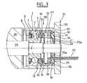
Sur la figure 1, le palier à roulement instrumenté, référencé 1 dans son ensemble, est prévu pour être monté sur l'extrémité d'un arbre tournant d'un moteur électrique non représenté. Le roulement 1 comprend une bague extérieure 2 pourvue d'un chemin de roulement 3, une bague intérieure 4 pourvue d'un chemin de roulement 5, une rangée d'éléments roulants 6, ici des billes, disposés entre les chemins de roulement 3 et 5, une cage 7 de maintien de l'espacement circonférentiel des éléments roulants 5 et un joint d'étanchéité 8 monté dans une rainure 9 de la bague extérieure 2 d'un côté de la rangée d'éléments roulants 6. Le roulement 1 est en outre équipé d'un ensemble de détection 10 se composant d'un codeur 11 et d'un ensemble capteur 12.In Figure 1, the instrumented rolling bearing, referenced 1 as a whole, is intended to be mounted on the end of a rotating shaft of an electric motor not shown. The bearing 1 comprises an
Le codeur 11 comprend un support annulaire 13 à section en S, avec une portion cylindrique emmanchée sur une portée extérieure de la bague intérieure tournante 4, une portion radiale dirigée vers l'extérieur et une autre portion cylindrique orientée à l'opposé des éléments roulants 6, et une partie active 14 sous la forme d'un anneau multipolaire réalisé en plastoferrite ou en élastoferrite surmoulé sur le support 13, la partie active 14 étant disposée axialement en saillie par rapport aux surfaces frontales radiales délimitant les bagues extérieure 2 et intérieure 4 du roulement 1.The
L'ensemble capteur 12 comprend un bloc capteur 15 en matériau synthétique, solidarisé de façon rigide à la bague extérieure 2. Le bloc capteur 15 vient en contact avec la surface radiale frontale de la bague extérieure 2 du côté opposé au joint d'étanchéité 8 et vient se fixer dans une rainure 16 symétrique de la rainure 8 par rapport à un plan passant par le centre des éléments roulants 6. Le bloc capteur 15 comprend une partie substantiellement radiale 17 disposée axialement entre les éléments roulants 6 et la partie radiale du support 13 du codeur 11 et radialement entre la rainure 16 et la partie cylindrique du support 13 emmanchée sur la portée extérieure de la bague intérieure 4, et une partie 18 substantiellement tubulaire présentant un diamètre extérieur légèrement inférieur au diamètre extérieur de la bague extérieure 2 et s'étendant axialement à l'opposé des éléments roulants 6. La partie tubulaire 18 comprend un alésage 19 pourvu d'un épaulement 20. La partie tubulaire 18 entoure radialement la partie active 14 du codeur 11.The
L'ensemble capteur 12 comprend également une carte 21 de circuit imprimé ou de circuit intégré de forme annulaire montée dans l'alésage 19 jusqu'à contact avec l'épaulement 20 disposé sensiblement au milieu de la partie tubulaire 18, un ou plusieurs éléments capteurs 22 supportés par la carte 21 du côté du codeur 11, et une nappe de connexion 23. La carte 21 possède un alésage permettant de laisser passer un arbre de moteur. Le ou les éléments capteurs 22 peuvent être du type à effet Hall. La nappe de connexion 23 est reliée à la carte 21 du côté opposé aux éléments capteurs 22 et comprend une pluralité de conducteurs 24 susceptibles de transmettre de l'énergie et/ou des signaux électriques. Le ou les éléments capteurs 22 sont disposé avec un léger entrefer axial par rapport à la partie active 14 du codeur 11.The
Le roulement 1 comprend en outre un organe de précontrainte axiale 25, se présentant ici sous la forme d'une rondelle ondulée, disposé dans l'alésage 19 et en contact avec la carte 21 par une surface 25a du même côté que la nappe de connexion 23. A l'extrémité libre de la partie tubulaire 18 du bloc capteur 15, sont formés une pluralité de doigts parmi lesquels trois doigts 26 assurent la retenue axiale de la carte 21 de façon qu'elle soit immobilisée axialement entre l'épaulement 20 et les doigts 26. Les doigts 26 s'étendent radialement vers l'intérieur en saillie par rapport à l'alésage 19.The bearing 1 further comprises an
Il est également prévu trois autres doigts de retenue 27 également circonférentiellement répartis pour la retenue de l'organe de précontrainte axiale 25 faisant également saillie vers l'intérieur par rapport à l'alésage 19. Les doigts de retenue 27 sont en contact avec une surface 25b de l'organe de précontrainte axiale 25 du côté opposé à la surface 25a. L'organe de précontrainte axiale 25 constitue avec le roulement 1 un sous-ensemble prémonté qui peut être assemblé de façon économique avec les autres constituants d'un moteur électrique.There are also three other retaining
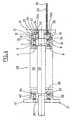
Comme on peut le voir sur la figure 3, le roulement instrumenté 1 est monté dans un moteur 28 dont seule une partie de l'extrémité est représentée. L'alésage de la bague intérieure 4 est monté avec serrage sur un arbre 29 solidaire d'un rotor 30. La bague extérieure 2 est montée dans un carter moteur 31 comportant généralement plusieurs éléments et dont seulement une partie est représentée. La bague extérieure 2 est montée avec un ajustement glissant dans une portion tubulaire 32 du carter 31. Le carter 31 comporte également une partie radiale 33 disposée à l'extrémité de la partie tubulaire 32 opposée au rotor 30 et présentant une forme annulaire avec un alésage 34 par lequel passe l'extrémité de l'arbre 29 et la nappe de connexion 24. La surface 25b de l'organe de précontrainte axiale 25 est en appui sur la face radiale intérieure de la partie radiale 33 du carter 31. Ainsi, l'organe de précontrainte axiale 25 tend à pousser la bague extérieure 2 vers le rotor 30 par l'intermédiaire de la carte 21 et du bloc capteur 15, ce qui permet une précharge axiale du roulement 1.As can be seen in Figure 3, the instrumented bearing 1 is mounted in a
Sur la figure 4, le moteur 28 est partiellement représenté de façon schématique. L'extrémité de l'arbre 29 opposée au roulement 1 est équipée d'un roulement 35 de type conventionnel non instrumenté à une rangée d'éléments roulants, comprenant une bague extérieure 36, une rangée d'éléments roulants 37, ici des billes, une bague intérieure 38 solidaire de l'arbre 29 par emmanchement serré et un élément d'étanchéité 39 solidaire de la bague extérieure 36 et venant former un passage étroit avec la bague intérieure 38. La bague extérieure 36 est montée dans le carter 31 du moteur, qui comprend une partie tubulaire 40 et une partie radiale 41 disposée à l'extrémité de la partie tubulaire 40 opposée au rotor 30, laissant ouvert un passage central dans lequel l'arbre 29 fait saillie. La bague extérieure 36 du roulement 35 peut être emmanchée à force dans la partie tubulaire 40. Bien entendu, les différentes parties du carter 32, 33, 40 et 41 sont fermement liées ensemble de façon non représentée.In Figure 4, the
La précontrainte axiale exercée par l'organe de précontrainte axiale 25 se transmet de la bague extérieure 2 du roulement 1 à la bague intérieure 4 par l'intermédiaire des éléments roulants 6, puis à l'arbre 29, à la bague intérieure 38 du roulement 35, aux éléments roulants 37 et à la bague extérieure 36. On comprend que la présence d'un seul organe de précontrainte axiale 25 permet de précharger axialement le roulement 1 et le roulement 35 tout en s'accomodant des dilatations différentes de l'arbre en général en acier et du carter en général à base d'aluminium, le roulement 1 pouvant glisser axialement par rapport au carter qui le supporte.The axial preload exerted by the
L'assemblage du roulement 1 est effectué de la façon suivante. On positionne la carte 21 dans l'alésage 19 du bloc capteur 15 jusqu'à venir en butée contre l'épaulement 20. On positionne ensuite l'organe de précontrainte axiale 25 dans l'alésage 19 contre la carte 21. On déforme ensuite par chauffage des pions issus de l'extrémité libre de la partie tubulaire 18 du bloc capteur 15 pour former les doigts de retenue 26 et 27 qui assurent le positionnement définitif et la retenue axiale de la carte 21 et de l'organe de retenue axiale 25.The assembly of the bearing 1 is carried out as follows. The
L'organe de retenue axiale 25 est ainsi en appui sur une partie du moteur extérieure au palier à roulement et exerce par réaction une précontrainte axiale la bague non tournante, les éléments roulants et la bague tournante. Le roulement est préchargé axialement. Dans le mode réalisation représenté, la précharge est transmise par la carte 21 et le bloc capteur 15, toutefois on peut aussi prévoir un contact direct de l'organe de retenue axiale 25 avec le bloc capteur 15 ou encore avec la bague non tournante.The
Bien entendu, on pourrait prévoir une bague extérieure tournante et une bague intérieure non tournante en fonction de la machine à laquelle le roulement est destiné. Les termes " tournant" et "non tournant" s'entendent de façon relative.Of course, one could provide a rotating outer ring and a non-rotating inner ring depending on the machine to which the bearing is intended. The terms "turning" and "non-turning" mean relatively.
L'ensemble ainsi obtenu est particulièrement compact. Son transport et sa manipulation se font en toute sécurité sans risque de perte de la rondelle élastique. Le fabriquant de moteurs a une pièce en moins à approvisionner, à gérer et à monter. Le montage de l'ensemble dans le moteur est particulièrement aisé et ne demande aucune précaution particulière. On assure ainsi avec un seul ensemble de palier à roulement, la fonction palier, une fonction électronique de détection, par exemple la détection de la vitesse ou la détection dans la position angulaire et la fonction mécanique de mise en précontrainte axiale des roulements du moteur.The assembly thus obtained is particularly compact. Its transport and its manipulation are done safely without risk of loss of the elastic washer. The engine manufacturer has one less room to supply, manage and assemble. Mounting the assembly in the engine is particularly easy and requires no special precautions. Thus, with a single rolling bearing assembly, the bearing function is provided with an electronic detection function, for example the detection of the speed or the detection in the angular position and the mechanical function of axially placing the motor bearings in axial prestressing.
Claims (14)
- Instrumented rolling bearing device (1) of the type comprising a non-rotating race (2), a rotating race (4), at least one row of rolling elements (6) arranged between two raceways (3, 5) of the rotating (4) and non-rotating (2) races, an assembly (10) for detecting rotation parameters comprising a non-rotating sensor assembly (12) and a rotating annular encoder (11), and an elastic member (25), for axially prestressing the rolling bearing, the prestress passing through the rolling elements, said elastic member (25) being of annular shape and having a diameter smaller than or equal to that of the outer race of the bearing, said elastic member (25) comprising a supporting surface designed to be in contact with an element outside said device in order to exert, by reaction, an axial force on the non-rotating race (2) in a direction opposite to the detection assembly (10),characterized in that said elastic member (25) is retained axially on the sensor assembly, the axial force being exerted directly or indirectly.
- Device according to Claim 1,characterized in that the elastic member (25) is a corrugated washer.
- Device according to Claim 1,characterized in that the elastic member is a conical washer.
- Device according to any one of the preceding claims,characterized in that the elastic member is a washer provided with elastic tongues.
- Device according to any one of the preceding claims,characterized in that the sensor assembly (12) comprises a body fitted with means for retaining the elastic member (25).
- Device according to Claim 5,characterized in that said retaining means comprise at least one finger (27).
- Device according to any one of the preceding claims,characterized in that the sensor assembly (12) comprises a printed circuit (21) and at least one sensor element (22) supported by the printed circuit, the elastic member (25) being in contact with the printed circuit on an opposite side to the sensor element (22).
- Device according to Claim 7,characterized in that the elastic member (25) is arranged axially between the printed circuit (21) and means for retaining said elastic member (25), forming part of the sensor assembly (12).
- Device according to any one of the preceding claims,characterized in that the rolling elements (6) transmit said axial prestress.
- Device according to any one of the preceding claims,characterized in that the elastic member (25) for axially prestressing the rolling bearing pushes the non-rotating race (2) away from said assembly (10) for detecting rotation parameters.
- Assembly (10) for detecting rotation parameters, intended to be mounted in a bearing, comprising a non-rotating sensor assembly (12), a rotating annular encoder (11), and an axially prestressing elastic member (25), said elastic member (25) being of annular shape, said elastic member (25) having a diameter smaller than or equal to that of the detection assembly, said elastic member (25) comprising a supporting surface designed to be in contact with an element outside said device in order to exert, by reaction, an axial force on the detection assembly in a direction opposite to the detection assembly (10),characterized in that the elastic member (25) is retained axially on the sensor assembly (12), the axial force being exerted directly or indirectly.
- Assembly according to Claim 11,characterized in that the elastic member (25) comprises a washer.
- Electric motor (28) comprising a rotor (30), a stator and an instrumented rolling bearing device (1) according to any one of Claims 1 to 10.
- Motor according to Claim 13,characterized in that the elastic member (25) is arranged between the sensor assembly (12) and a non-rotating part of the motor.
Applications Claiming Priority (2)
| Application Number | Priority Date | Filing Date | Title |
|---|---|---|---|
| FR0302363AFR2851624B1 (en) | 2003-02-26 | 2003-02-26 | INSTRUMENT BEARING BEARING |
| FR0302363 | 2003-02-26 |
Publications (2)
| Publication Number | Publication Date |
|---|---|
| EP1452753A1 EP1452753A1 (en) | 2004-09-01 |
| EP1452753B1true EP1452753B1 (en) | 2006-05-03 |
Family
ID=32749732
Family Applications (1)
| Application Number | Title | Priority Date | Filing Date |
|---|---|---|---|
| EP04290379AExpired - LifetimeEP1452753B1 (en) | 2003-02-26 | 2004-02-12 | Roller bearing with integrated sensor |
Country Status (7)
| Country | Link |
|---|---|
| US (1) | US7367714B2 (en) |
| EP (1) | EP1452753B1 (en) |
| JP (1) | JP2004257557A (en) |
| AT (1) | ATE325282T1 (en) |
| DE (1) | DE602004000775T2 (en) |
| ES (1) | ES2259171T3 (en) |
| FR (1) | FR2851624B1 (en) |
Families Citing this family (39)
| Publication number | Priority date | Publication date | Assignee | Title |
|---|---|---|---|---|
| FR2820476B1 (en)* | 2001-02-02 | 2004-04-02 | Skf Ab | DEVICE FOR DETECTING THE ROTATION SPEED OF A ROTATING ELEMENT |
| FR2829429B1 (en)* | 2001-09-12 | 2003-12-12 | Skf Ab | STOP SUSPENSION DEVICE |
| FR2832201B1 (en)* | 2001-11-13 | 2004-03-19 | Skf Ab | INSTRUMENT TENSIONING DEVICE AND ASSOCIATED CONTROL METHOD |
| FR2835297B1 (en) | 2002-01-29 | 2004-04-16 | Skf Ab | FIXING SUPPORT, ROLLING BEARING AND ASSEMBLY METHOD THEREFOR |
| FR2841304B1 (en) | 2002-06-20 | 2007-01-05 | Skf Ab | VOLTAGE DEVICE FOR PRECONTRATING ROD AND ASSOCIATED VOLTAGE METHOD |
| FR2841990B1 (en)* | 2002-07-02 | 2005-07-29 | Skf Ab | INSTRUMENTAL BEARING BEARING DEVICE AND ELECTRIC MOTOR THUS EQUIPPED |
| FR2853165B1 (en)* | 2003-03-27 | 2005-12-02 | Skf Ab | SENSOR ASSEMBLY, AND HOUSING FOR CARRYING OUT SUCH AN ASSEMBLY. |
| FR2853065B1 (en)* | 2003-03-27 | 2006-01-06 | Skf Ab | PORTABLE MEASURING INSTRUMENT, PARTICULARLY FOR SPORT PRACTICE. |
| FR2856757B1 (en)* | 2003-06-27 | 2006-10-20 | Skf Ab | INSTRUMENT BEARING BEARING AND ENCODER FOR INFORMATION SENSOR ASSEMBLY |
| FR2858376B1 (en)* | 2003-07-28 | 2006-03-03 | Skf France | FREEWHEEL BEARING DEVICE WITH TORQUE LIMITER. |
| FR2860847B1 (en) | 2003-10-14 | 2006-03-31 | Skf Ab | CLUTCH STOPPING DEVICE |
| FR2872558B1 (en)* | 2004-07-02 | 2006-09-29 | Skf Ab | CLUTCH FASTER AND METHOD OF MANUFACTURE |
| FR2882580B1 (en)* | 2005-02-28 | 2007-05-25 | Skf Ab | INSTRUMENT BELT TENSIONER ROLLING DEVICE AND METHOD OF CONTROLLING THE SAME |
| DE202005016992U1 (en)* | 2005-10-31 | 2005-12-29 | Litens Automotive Gmbh | Belt tightener for a belt drive in an internal combustion engine comprises a glide element arrangement incorporating at least two opposing gliding surfaces are made of the same material |
| FR2902699B1 (en) | 2006-06-26 | 2010-10-22 | Skf Ab | SUSPENSION STOP DEVICE AND FORCE LEG. |
| FR2904671B1 (en)* | 2006-08-02 | 2009-03-13 | Skf Ab | INSTRUMENT JOINT SYSTEM. |
| FR2906587B1 (en) | 2006-10-03 | 2009-07-10 | Skf Ab | TENDERING ROLLER DEVICE. |
| FR2913081B1 (en) | 2007-02-27 | 2009-05-15 | Skf Ab | DEBRAYABLE PULLEY DEVICE |
| FR2915280B1 (en)* | 2007-04-19 | 2009-07-10 | Skf Ab | INSTRUMENT JOINT SYSTEM. |
| FR2917476B1 (en)* | 2007-06-12 | 2010-02-26 | Skf Ab | INSTRUMENT BEARING DEVICE WITH INDEXING |
| FR2918221B1 (en)* | 2007-06-29 | 2009-12-25 | Skf Ab | SHAFT SUPPORT SYSTEM FOR ELECTRIC MOTOR, ELECTRIC MOTOR AND ASSEMBLY METHOD. |
| US20090027043A1 (en)* | 2007-07-26 | 2009-01-29 | Dematic Corp. | Roller encoder |
| WO2010038102A1 (en)* | 2008-10-03 | 2010-04-08 | Aktiebolaget Skf | Pin for a joint between two pivoting parts, joint system provided with such a pin, automotive vehicle equipped with such a joint system and process for manufacturing such a pin |
| WO2010038103A1 (en)* | 2008-10-03 | 2010-04-08 | Aktiebolaget Skf | Detection assembly and pin for a joint between two pivoting parts |
| JP2011012796A (en)* | 2009-07-06 | 2011-01-20 | Ntn Corp | Bearing with rotation sensor |
| WO2011045631A1 (en)* | 2009-10-12 | 2011-04-21 | Aktiebolaget Skf | Sensor unit, support member, rolling bearing assembly and method for assembling such a rolling bearing assembly |
| US20120144939A1 (en)* | 2010-12-13 | 2012-06-14 | Arne Lars Jonas Kullin | Double Bearing Assembly for Rotating Shaft |
| JP2012220192A (en)* | 2011-04-04 | 2012-11-12 | Ntn Corp | Roller bearing device having rotation detection function |
| DE102011085711A1 (en) | 2011-11-03 | 2013-05-08 | Schaeffler Technologies AG & Co. KG | Roller bearing for use as e.g. grooved ball bearing, has force measuring unit provided with force sensor held in bearing cage in place of roller bodies, where force sensor wirelessly transmits sensor signals to evaluation device |
| EP2682621B1 (en)* | 2012-07-05 | 2015-02-25 | Aktiebolaget SKF | Instrumented bearing |
| EP2918845B2 (en) | 2014-03-11 | 2022-01-12 | Skf Magnetic Mechatronics | Rotary machine and method for manufacturing a rotary machine |
| WO2016192752A1 (en)* | 2015-05-29 | 2016-12-08 | Aktiebolaget Skf | Rolling bearing assembly with pre-stressing element and sensor unit |
| CN105003552B (en)* | 2015-07-23 | 2018-03-06 | 张露丹 | A kind of two-way bearing of electrical control |
| CN105065470B (en)* | 2015-07-23 | 2018-07-10 | 衢州熊妮妮计算机科技有限公司 | A kind of two-way bearing of electric limiting |
| DE102018211843A1 (en) | 2018-07-17 | 2020-01-23 | Ziehl-Abegg Se | Electric motor and fan with a corresponding electric motor |
| DE102019127241A1 (en)* | 2019-10-10 | 2021-04-15 | Dr. Ing. H.C. F. Porsche Aktiengesellschaft | Bearing arrangement |
| US11821467B2 (en) | 2021-05-17 | 2023-11-21 | Aktiebolaget Skf | Sensor bearing unit |
| US11982317B2 (en) | 2021-05-17 | 2024-05-14 | Aktiebolaget Skf | Sensor bearing unit |
| CN115711262B (en)* | 2021-08-23 | 2023-06-16 | 中国科学院理化技术研究所 | Spindle support structure of a rotating machine and the rotating machine |
Family Cites Families (94)
| Publication number | Priority date | Publication date | Assignee | Title |
|---|---|---|---|---|
| FR2304829A1 (en) | 1975-03-21 | 1976-10-15 | Ferodo Sa | RELEASE STOP |
| US4046238A (en) | 1976-02-03 | 1977-09-06 | Mendoza Orozco Hector | Free-wheeling mechanism for bicycles |
| US4319220A (en) | 1976-08-31 | 1982-03-09 | Dennis G. Pappas | Alarm system for monitoring pressurized vehicular tires |
| FR2384990A1 (en) | 1977-03-25 | 1978-10-20 | Skf Cie Applic Mecanique | ELASTIC SELF-ALIGNING CLUTCH STOPPER WITH GUIDING MEANS |
| FR2461158A1 (en) | 1979-07-10 | 1981-01-30 | Skf Cie Applic Mecanique | SELF-CENTERING CLUTCH STOP |
| JPS595226Y2 (en)* | 1979-12-10 | 1984-02-16 | 東芝テック株式会社 | bearing device |
| JPS57161344A (en) | 1981-03-27 | 1982-10-04 | Nippon Denso Co Ltd | Belt tension control device |
| US4601374A (en) | 1982-04-22 | 1986-07-22 | Federal-Mogul Corporation | Hydraulic clutch piston and seal |
| FR2544429B1 (en) | 1983-04-15 | 1985-08-02 | Valeo | METHOD FOR MOUNTING A RELEASE STOPPER, AND CORRESPONDING RELEASE STOPPER, PARTICULARLY FOR A MOTOR VEHICLE |
| DE3445541A1 (en) | 1984-01-04 | 1985-07-11 | Skandiafabriken AB, Mullsjö | LIQUID LEVEL INDICATOR |
| GB8407519D0 (en) | 1984-03-22 | 1984-05-02 | Cambridge Electronic Ind | Tachogenerators |
| FR2568258B1 (en)* | 1984-07-25 | 1987-02-13 | Inst Francais Du Petrole | POLYIMIDE PRECURSOR COMPOSITIONS, THEIR PREPARATION, THE POLYIMIDES DERIVATIVE THEREOF AND THEIR USES, IN PARTICULAR IN THE MANUFACTURE OF ENAMELING VARNISHES FOR ELECTRICAL CONDUCTORS |
| JPS61101465U (en)* | 1984-12-07 | 1986-06-28 | ||
| FR2577291B1 (en) | 1985-02-08 | 1989-10-13 | Valeo | SELF-CENTERING CLUTCH STOPPER, PARTICULARLY FOR MOTOR VEHICLE, WITH SIMPLIFIED COMPACT ASSEMBLY |
| US5033013A (en) | 1985-04-22 | 1991-07-16 | Yamasa Tokei Meter Co., Ltd. | Method and apparatus for measuring the amount of exercise |
| US4699530A (en) | 1985-06-28 | 1987-10-13 | Oiless Industry Co., Ltd. | Thrust ball bearing unit |
| JPS634150U (en)* | 1986-06-24 | 1988-01-12 | ||
| FR2602872B1 (en) | 1986-08-05 | 1989-03-31 | Renault | ANGULAR SPEED SENSOR AND ITS APPLICATION TO A COMBINED TORQUE AND ANGULAR SPEED SENSOR FOR A STEERING COLUMN OF A MOTOR VEHICLE |
| FR2609126B1 (en) | 1986-12-29 | 1989-10-27 | Valeo | RELEASE STOP, ESPECIALLY FOR A MOTOR VEHICLE |
| FR2611009B1 (en) | 1987-02-17 | 1989-05-19 | Valeo | RELEASE STOP, ESPECIALLY FOR A MOTOR VEHICLE |
| JPS63246516A (en) | 1987-04-02 | 1988-10-13 | Nippon Seiko Kk | Clutch release bearing device |
| US4815867A (en) | 1987-09-23 | 1989-03-28 | Federal-Mogul Corporation | Side assembled clip for self-aligning bearing |
| DE3742030C2 (en) | 1987-12-11 | 1997-06-19 | Skf Gmbh | Swivel bearing for clamping devices |
| DE8810259U1 (en) | 1988-08-12 | 1988-11-17 | Messer Griesheim Gmbh, 6000 Frankfurt | Flushing block |
| FR2640706B1 (en) | 1988-12-20 | 1991-02-01 | Roulements Soc Nouvelle | INFORMATION SENSOR BEARING |
| US5008647A (en) | 1989-02-06 | 1991-04-16 | Orleander S.A. | Wireless bicycle wheel monitor system |
| FR2645929B1 (en) | 1989-04-18 | 1991-06-07 | Roulements Soc Nouvelle | DEVICE FOR CLAMPING A THRUST BEARING ON A SLIDING SUPPORT |
| US5018384A (en)* | 1989-07-21 | 1991-05-28 | Nippon Seiko Kabushiki Kaisha | Rotational speed detector |
| FR2655735B1 (en) | 1989-12-07 | 1994-05-13 | Skf France | ROTATION SPEED SENSOR DEVICE. |
| IT1240481B (en) | 1990-07-04 | 1993-12-17 | Skf Ind Spa | DEVICE SUITABLE FOR ALLOWING THE ROTATION SPEED TO BE DETECTED BETWEEN TWO BODIES IN RELATIVE ROTATION SUCH AS THE SUPPORT BODIES OF A WHEEL OF A VEHICLE. |
| US5051693A (en)* | 1990-09-07 | 1991-09-24 | The Torrington Company | Bearing seat encoder mount for rotational parameter sensor apparatus |
| FR2675860B1 (en)* | 1991-04-24 | 1993-08-20 | Jaeger | BEARING COMPRISING A SPEED SENSOR. |
| FR2678329B1 (en) | 1991-06-28 | 1993-09-03 | Roulements Soc Nouvelle | SEALING MOUNT FOR INFORMATION SENSOR SUITABLE FOR A SEALED BEARING. |
| IT1256785B (en) | 1992-01-28 | 1995-12-15 | Skf Ind Spa | SEALING COMPLEX WITH A SENSOR DEVICE ON BOARD, FOR A ROLLING BEARING. |
| DE4228988A1 (en)* | 1992-08-31 | 1994-03-03 | Hackewitz Friedrich W Von Dr I | Lubrication monitor for rotating machine part - has inductive sensor for rotational speed and with program to monitor lubricant thickness |
| JP2602146Y2 (en)* | 1993-04-19 | 1999-12-27 | 日本精工株式会社 | Rolling bearing with rotation detection device |
| DE9418459U1 (en) | 1994-11-18 | 1995-02-02 | FAG OEM und Handel AG, 97421 Schweinfurt | Rolling bearing with speed sensor |
| US6539336B1 (en) | 1996-12-12 | 2003-03-25 | Phatrat Technologies, Inc. | Sport monitoring system for determining airtime, speed, power absorbed and other factors such as drop distance |
| DE19503469C1 (en) | 1995-02-03 | 1996-05-30 | Freudenberg Carl Fa | Seal for relatively rotating components cooperating with rotation sensor |
| FR2730566B1 (en) | 1995-02-09 | 1997-06-13 | Skf France | ENCODER DEVICE FOR ROTATION SPEED SENSOR AND BEARING PROVIDED WITH SUCH A DEVICE |
| FR2730534B1 (en) | 1995-02-09 | 1997-04-04 | Valeo | HYDRAULICALLY CONTROLLED CLUTCH STOPPER FOR A MOTOR VEHICLE DIAPHRAGM CLUTCH |
| US5592401A (en) | 1995-02-28 | 1997-01-07 | Virtual Technologies, Inc. | Accurate, rapid, reliable position sensing using multiple sensing technologies |
| JPH08292111A (en) | 1995-04-24 | 1996-11-05 | Mitsubishi Electric Corp | Belt tension measuring device |
| US5598913A (en) | 1995-06-07 | 1997-02-04 | Ntn Corporation | One-way over-running clutch pulley |
| US6011491A (en) | 1995-10-10 | 2000-01-04 | Goetzl; Brent A. | Speedometer for in-line skates |
| US5721539A (en) | 1995-10-10 | 1998-02-24 | Goetzl; Brent A. | Speedometer for in-line skates |
| US5845230A (en) | 1996-01-30 | 1998-12-01 | Skf Condition Monitoring | Apparatus and method for the remote monitoring of machine condition |
| DE19614385A1 (en) | 1996-03-04 | 1997-09-11 | Schaeffler Waelzlager Kg | Seal for an annular piston of a hydraulic clutch release device |
| US5780731A (en) | 1996-04-11 | 1998-07-14 | Denso Corporation | Method for judging the locked state of auxiliaries for automobiles |
| FR2748536B1 (en) | 1996-05-09 | 1998-07-03 | Skf France | ELASTIC WASHER CLUTCH STOP DEVICE |
| DE29615910U1 (en) | 1996-08-05 | 1997-12-04 | Lumpert, Jürg B., Zürich | Sports equipment with data display for the user |
| DE19637585C2 (en) | 1996-09-14 | 1999-07-01 | Bernd Voelkel | Speedometer for roller skates |
| FR2754903B1 (en) | 1996-10-23 | 1998-12-04 | Skf France | ENCODER DEVICE FOR ROTATION SPEED SENSOR AND BEARING PROVIDED WITH SUCH A DEVICE |
| US6415900B1 (en) | 1996-12-23 | 2002-07-09 | Valeo | Hydraulic control receiver with closing plate |
| DE19716218C2 (en) | 1997-04-18 | 2001-08-30 | Schaeffler Waelzlager Ohg | Clutch release bearing |
| DE29708535U1 (en) | 1997-05-05 | 1997-08-28 | Zimmermann, Hartmut, Dr.rer.nat., 12589 Berlin | Device for recording movement parameters during in-line skating |
| BR9809790A (en) | 1997-05-07 | 2000-06-27 | Litens Automotive Inc | System driven by serpentine belt for an automotive vehicle, and device to transmit movement from a belt driven by an engine output shaft to an auxiliary component shaft to be driven |
| DE19809074A1 (en) | 1997-06-30 | 1999-01-07 | Schaeffler Waelzlager Ohg | Strut mounting for shock absorber in motor vehicle front wheel suspension |
| FR2772920B1 (en) | 1997-12-18 | 2000-02-04 | Skf France | IN-LINE SKATE WHEEL MOUNTING WITH ROTATION SPEED DETECTION DEVICE |
| ITTO980035A1 (en) | 1998-01-16 | 1999-07-16 | Skf Ind Spa | ROLLING BEARING WITH ROTATION SPEED DETECTION DEVICE. |
| US6013007A (en) | 1998-03-26 | 2000-01-11 | Liquid Spark, Llc | Athlete's GPS-based performance monitor |
| FR2779096B1 (en) | 1998-05-28 | 2000-12-15 | Skf France | SUSPENSION STOP DEVICE |
| US6196552B1 (en) | 1998-06-08 | 2001-03-06 | Automotive Products (Usa), Inc. | Seal assembly for annular hydraulic cylinder |
| GB9813961D0 (en) | 1998-06-30 | 1998-08-26 | Renold Plc | Method and apparatus for tensioning a chain of an internal combustion engine |
| JP2000065847A (en)* | 1998-08-20 | 2000-03-03 | Nippon Seiko Kk | Rolling bearing unit with rotation speed detector |
| IT1304673B1 (en) | 1998-10-06 | 2001-03-28 | Skf Ind Spa | METHOD FOR THE CONSTRUCTION OF A PHONIC WHEEL FOR A ROLLING BEARING, AND RELATED PRODUCT. |
| FR2791103B1 (en) | 1999-03-17 | 2001-04-13 | Skf France | INSTRUMENT BEARING |
| US6160480A (en) | 1999-09-24 | 2000-12-12 | Su-Yueh; Hsien Huang | Wireless inline-skate and skate board pulse watch with speed and heart rate monitoring |
| US6666784B1 (en) | 1999-10-06 | 2003-12-23 | Ntn Corporation | Piston rod piston detector, autotensioner and belt tension adjuster |
| WO2001042809A2 (en) | 1999-12-07 | 2001-06-14 | Esport Incorporated | Gps athletic performance monitor methods and apparatus thereof |
| DE19960699B4 (en) | 1999-12-16 | 2010-09-30 | Schaeffler Technologies Gmbh & Co. Kg | Strut bearing |
| DE10011820B4 (en) | 2000-03-10 | 2012-01-12 | Schaeffler Technologies Gmbh & Co. Kg | Measuring device for rolling bearings |
| FR2807802B1 (en) | 2000-04-12 | 2002-07-26 | Skf France | RELEASE STOP AND DRIVING ELEMENT FOR RELEASE STOP |
| IT1320364B1 (en) | 2000-05-25 | 2003-11-26 | A E Assemblaggi Elettromeccani | WEAR SENSOR DEVICE OF A DRIVE BELT OR CHAIN, IN PARTICULAR FOR A DRIVE SHAFT OF THE DRIVE SHAFT |
| DE50011024D1 (en) | 2000-06-16 | 2005-09-29 | Amo Automatisierung Mestechnik | Inductive length measuring system |
| FR2813644B1 (en) | 2000-09-06 | 2003-01-24 | Skf France | INSTRUMENTED ROLLING BEARING DEVICE, PARTICULARLY FOR CONTROL WHEEL |
| FR2818708B1 (en)* | 2000-12-22 | 2003-04-25 | Skf Ab | BL0C SENSOR HOLDER AND ROLLING BEARING WITH INFORMATION SENSOR |
| BR0108568B1 (en) | 2000-12-22 | 2009-12-01 | clutch stop and mounting process for a piston with a bearing. | |
| FR2819864B1 (en) | 2001-01-23 | 2003-04-25 | Skf Ab | SELF-CENTERING RELEASE STOP DEVICE |
| FR2820476B1 (en) | 2001-02-02 | 2004-04-02 | Skf Ab | DEVICE FOR DETECTING THE ROTATION SPEED OF A ROTATING ELEMENT |
| JP2002266855A (en)* | 2001-03-09 | 2002-09-18 | Japan Servo Co Ltd | Housing structure storing bearing and spring |
| FR2829429B1 (en) | 2001-09-12 | 2003-12-12 | Skf Ab | STOP SUSPENSION DEVICE |
| DE10148388A1 (en) | 2001-09-29 | 2003-04-24 | Ina Schaeffler Kg | Roller bearing for a clutch disengagement unit, comprises a rotating ring, a fixed ring, an inner chamber and ball bearings |
| FR2832201B1 (en) | 2001-11-13 | 2004-03-19 | Skf Ab | INSTRUMENT TENSIONING DEVICE AND ASSOCIATED CONTROL METHOD |
| FR2835297B1 (en) | 2002-01-29 | 2004-04-16 | Skf Ab | FIXING SUPPORT, ROLLING BEARING AND ASSEMBLY METHOD THEREFOR |
| FR2841304B1 (en) | 2002-06-20 | 2007-01-05 | Skf Ab | VOLTAGE DEVICE FOR PRECONTRATING ROD AND ASSOCIATED VOLTAGE METHOD |
| FR2841990B1 (en) | 2002-07-02 | 2005-07-29 | Skf Ab | INSTRUMENTAL BEARING BEARING DEVICE AND ELECTRIC MOTOR THUS EQUIPPED |
| FR2853165B1 (en) | 2003-03-27 | 2005-12-02 | Skf Ab | SENSOR ASSEMBLY, AND HOUSING FOR CARRYING OUT SUCH AN ASSEMBLY. |
| FR2856448B1 (en) | 2003-06-18 | 2006-09-01 | Skf Ab | STOP CLUTCH |
| FR2856447B1 (en) | 2003-06-18 | 2005-09-09 | Skf Ab | CLUTCH FASTENING AND MOUNTING METHOD |
| FR2856757B1 (en) | 2003-06-27 | 2006-10-20 | Skf Ab | INSTRUMENT BEARING BEARING AND ENCODER FOR INFORMATION SENSOR ASSEMBLY |
| FR2859412B1 (en) | 2003-09-04 | 2006-02-24 | Skf Ab | STOP SUSPENSION DEVICE |
| FR2860847B1 (en) | 2003-10-14 | 2006-03-31 | Skf Ab | CLUTCH STOPPING DEVICE |
| FR2872558B1 (en) | 2004-07-02 | 2006-09-29 | Skf Ab | CLUTCH FASTER AND METHOD OF MANUFACTURE |
- 2003
- 2003-02-26FRFR0302363Apatent/FR2851624B1/ennot_activeExpired - Fee Related
- 2004
- 2004-02-12EPEP04290379Apatent/EP1452753B1/ennot_activeExpired - Lifetime
- 2004-02-12ESES04290379Tpatent/ES2259171T3/ennot_activeExpired - Lifetime
- 2004-02-12DEDE602004000775Tpatent/DE602004000775T2/ennot_activeExpired - Fee Related
- 2004-02-12ATAT04290379Tpatent/ATE325282T1/ennot_activeIP Right Cessation
- 2004-02-16JPJP2004038115Apatent/JP2004257557A/enactivePending
- 2004-02-20USUS10/783,389patent/US7367714B2/ennot_activeExpired - Fee Related
Also Published As
| Publication number | Publication date |
|---|---|
| EP1452753A1 (en) | 2004-09-01 |
| JP2004257557A (en) | 2004-09-16 |
| FR2851624B1 (en) | 2006-03-31 |
| ES2259171T3 (en) | 2006-09-16 |
| US20040202392A1 (en) | 2004-10-14 |
| US7367714B2 (en) | 2008-05-06 |
| ATE325282T1 (en) | 2006-06-15 |
| DE602004000775T2 (en) | 2006-11-16 |
| DE602004000775D1 (en) | 2006-06-08 |
| FR2851624A1 (en) | 2004-08-27 |
Similar Documents
| Publication | Publication Date | Title |
|---|---|---|
| EP1452753B1 (en) | Roller bearing with integrated sensor | |
| EP0475841B1 (en) | Rolling bearing with rotating electrical contacts | |
| EP0821240B1 (en) | Roller bearing with measuring sensor | |
| WO2007104894A1 (en) | Shaft support system for electric motor, electric motor and method for making same | |
| EP0875683B1 (en) | Rolling contact bearing with an information sensor | |
| FR2791103A1 (en) | INSTRUMENT BEARING | |
| EP1366370B1 (en) | Roller device with instrumented ball bearing | |
| FR2991412A1 (en) | BEARING BEARING DEVICE FOR STEERING COLUMN. | |
| FR3004769A1 (en) | BEARING BEARING DEVICE FOR STEERING COLUMN | |
| FR3004770A1 (en) | BEARING BEARING DEVICE FOR STEERING COLUMN | |
| FR2994721A1 (en) | CAGE FOR BEARING BEARING, BEARING BEARING AND ELECTRIC DIRECTION OF MOTOR VEHICLE | |
| FR2993332A1 (en) | CAGE FOR BEARING BEARING, BEARING BEARING AND ELECTRIC DIRECTION OF MOTOR VEHICLE | |
| EP1397690B1 (en) | Roller bearing equipped with an angular velocity sensor | |
| FR3001510A1 (en) | CAGE FOR BEARING, IN PARTICULAR FOR THE ELECTRIC DIRECTION BEARING OF A MOTOR VEHICLE | |
| FR2994722A1 (en) | CAGE FOR BEARING, IN PARTICULAR FOR MOTOR VEHICLE ELECTRIC DIRECTION BEARING | |
| EP1476760A2 (en) | Monitored roller bearing | |
| EP1433968B1 (en) | Compact locked antifriction roller bearing | |
| EP1693677A1 (en) | Device for detecting the rotation parameters of two elements | |
| FR3001511A1 (en) | CAGE FOR BEARING, IN PARTICULAR FOR MOTOR VEHICLE ELECTRIC DIRECTION BEARING | |
| EP1287267A1 (en) | Locked antifriction bearing | |
| FR2782758A1 (en) | Roller bearing for motor vehicle steering column, comprises an electrically conductive tolerance collar between the bearing race and the interior surface of the steering column | |
| WO2006030090A1 (en) | Bearing housing | |
| EP1619478A2 (en) | Detector of a wheel rotation parameter, particularly a vehicle wheel | |
| EP1473570A1 (en) | Rolling bearing with integrated speed sensing device | |
| FR2798170A1 (en) | Ball bearing unit for steering column of a motor vehicle, has a blocking washer to block the bearing on the shaft |
Legal Events
| Date | Code | Title | Description |
|---|---|---|---|
| PUAI | Public reference made under article 153(3) epc to a published international application that has entered the european phase | Free format text:ORIGINAL CODE: 0009012 | |
| AK | Designated contracting states | Kind code of ref document:A1 Designated state(s):AT BE BG CH CY CZ DE DK EE ES FI FR GB GR HU IE IT LI LU MC NL PT RO SE SI SK TR | |
| AX | Request for extension of the european patent | Extension state:AL LT LV MK | |
| RIN1 | Information on inventor provided before grant (corrected) | Inventor name:CHAUSSAT, SYLVAIN Inventor name:NIARFEIX, FRANEOIS | |
| 17P | Request for examination filed | Effective date:20040922 | |
| 17Q | First examination report despatched | Effective date:20050124 | |
| AKX | Designation fees paid | Designated state(s):AT BE BG CH CY CZ DE DK EE ES FI FR GB GR HU IE IT LI LU MC NL PT RO SE SI SK TR | |
| GRAP | Despatch of communication of intention to grant a patent | Free format text:ORIGINAL CODE: EPIDOSNIGR1 | |
| GRAS | Grant fee paid | Free format text:ORIGINAL CODE: EPIDOSNIGR3 | |
| GRAA | (expected) grant | Free format text:ORIGINAL CODE: 0009210 | |
| AK | Designated contracting states | Kind code of ref document:B1 Designated state(s):AT BE BG CH CY CZ DE DK EE ES FI FR GB GR HU IE IT LI LU MC NL PT RO SE SI SK TR | |
| PG25 | Lapsed in a contracting state [announced via postgrant information from national office to epo] | Ref country code:IT Free format text:LAPSE BECAUSE OF FAILURE TO SUBMIT A TRANSLATION OF THE DESCRIPTION OR TO PAY THE FEE WITHIN THE PRESCRIBED TIME-LIMIT;WARNING: LAPSES OF ITALIAN PATENTS WITH EFFECTIVE DATE BEFORE 2007 MAY HAVE OCCURRED AT ANY TIME BEFORE 2007. THE CORRECT EFFECTIVE DATE MAY BE DIFFERENT FROM THE ONE RECORDED. Effective date:20060503 Ref country code:SK Free format text:LAPSE BECAUSE OF FAILURE TO SUBMIT A TRANSLATION OF THE DESCRIPTION OR TO PAY THE FEE WITHIN THE PRESCRIBED TIME-LIMIT Effective date:20060503 Ref country code:IE Free format text:LAPSE BECAUSE OF FAILURE TO SUBMIT A TRANSLATION OF THE DESCRIPTION OR TO PAY THE FEE WITHIN THE PRESCRIBED TIME-LIMIT Effective date:20060503 Ref country code:SI Free format text:LAPSE BECAUSE OF FAILURE TO SUBMIT A TRANSLATION OF THE DESCRIPTION OR TO PAY THE FEE WITHIN THE PRESCRIBED TIME-LIMIT Effective date:20060503 Ref country code:GB Free format text:LAPSE BECAUSE OF FAILURE TO SUBMIT A TRANSLATION OF THE DESCRIPTION OR TO PAY THE FEE WITHIN THE PRESCRIBED TIME-LIMIT Effective date:20060503 Ref country code:RO Free format text:LAPSE BECAUSE OF FAILURE TO SUBMIT A TRANSLATION OF THE DESCRIPTION OR TO PAY THE FEE WITHIN THE PRESCRIBED TIME-LIMIT Effective date:20060503 Ref country code:NL Free format text:LAPSE BECAUSE OF FAILURE TO SUBMIT A TRANSLATION OF THE DESCRIPTION OR TO PAY THE FEE WITHIN THE PRESCRIBED TIME-LIMIT Effective date:20060503 Ref country code:CZ Free format text:LAPSE BECAUSE OF FAILURE TO SUBMIT A TRANSLATION OF THE DESCRIPTION OR TO PAY THE FEE WITHIN THE PRESCRIBED TIME-LIMIT Effective date:20060503 Ref country code:FI Free format text:LAPSE BECAUSE OF FAILURE TO SUBMIT A TRANSLATION OF THE DESCRIPTION OR TO PAY THE FEE WITHIN THE PRESCRIBED TIME-LIMIT Effective date:20060503 | |
| REG | Reference to a national code | Ref country code:GB Ref legal event code:FG4D Free format text:NOT ENGLISH | |
| REG | Reference to a national code | Ref country code:CH Ref legal event code:EP | |
| REF | Corresponds to: | Ref document number:602004000775 Country of ref document:DE Date of ref document:20060608 Kind code of ref document:P | |
| REG | Reference to a national code | Ref country code:IE Ref legal event code:FG4D Free format text:LANGUAGE OF EP DOCUMENT: FRENCH | |
| PG25 | Lapsed in a contracting state [announced via postgrant information from national office to epo] | Ref country code:DK Free format text:LAPSE BECAUSE OF FAILURE TO SUBMIT A TRANSLATION OF THE DESCRIPTION OR TO PAY THE FEE WITHIN THE PRESCRIBED TIME-LIMIT Effective date:20060803 Ref country code:SE Free format text:LAPSE BECAUSE OF FAILURE TO SUBMIT A TRANSLATION OF THE DESCRIPTION OR TO PAY THE FEE WITHIN THE PRESCRIBED TIME-LIMIT Effective date:20060803 | |
| REG | Reference to a national code | Ref country code:ES Ref legal event code:FG2A Ref document number:2259171 Country of ref document:ES Kind code of ref document:T3 | |
| PG25 | Lapsed in a contracting state [announced via postgrant information from national office to epo] | Ref country code:PT Free format text:LAPSE BECAUSE OF FAILURE TO SUBMIT A TRANSLATION OF THE DESCRIPTION OR TO PAY THE FEE WITHIN THE PRESCRIBED TIME-LIMIT Effective date:20061003 | |
| NLV1 | Nl: lapsed or annulled due to failure to fulfill the requirements of art. 29p and 29m of the patents act | ||
| GBV | Gb: ep patent (uk) treated as always having been void in accordance with gb section 77(7)/1977 [no translation filed] | Effective date:20060503 | |
| REG | Reference to a national code | Ref country code:IE Ref legal event code:FD4D | |
| PG25 | Lapsed in a contracting state [announced via postgrant information from national office to epo] | Ref country code:MC Free format text:LAPSE BECAUSE OF NON-PAYMENT OF DUE FEES Effective date:20070228 | |
| PLBE | No opposition filed within time limit | Free format text:ORIGINAL CODE: 0009261 | |
| STAA | Information on the status of an ep patent application or granted ep patent | Free format text:STATUS: NO OPPOSITION FILED WITHIN TIME LIMIT | |
| 26N | No opposition filed | Effective date:20070206 | |
| BERE | Be: lapsed | Owner name:A.B. SKF Effective date:20070228 | |
| PG25 | Lapsed in a contracting state [announced via postgrant information from national office to epo] | Ref country code:BE Free format text:LAPSE BECAUSE OF NON-PAYMENT OF DUE FEES Effective date:20070228 | |
| PG25 | Lapsed in a contracting state [announced via postgrant information from national office to epo] | Ref country code:GR Free format text:LAPSE BECAUSE OF FAILURE TO SUBMIT A TRANSLATION OF THE DESCRIPTION OR TO PAY THE FEE WITHIN THE PRESCRIBED TIME-LIMIT Effective date:20060804 | |
| PGFP | Annual fee paid to national office [announced via postgrant information from national office to epo] | Ref country code:ES Payment date:20080226 Year of fee payment:5 | |
| PGFP | Annual fee paid to national office [announced via postgrant information from national office to epo] | Ref country code:IT Payment date:20080226 Year of fee payment:5 | |
| PG25 | Lapsed in a contracting state [announced via postgrant information from national office to epo] | Ref country code:BG Free format text:LAPSE BECAUSE OF FAILURE TO SUBMIT A TRANSLATION OF THE DESCRIPTION OR TO PAY THE FEE WITHIN THE PRESCRIBED TIME-LIMIT Effective date:20060803 | |
| PGFP | Annual fee paid to national office [announced via postgrant information from national office to epo] | Ref country code:AT Payment date:20080122 Year of fee payment:5 | |
| PG25 | Lapsed in a contracting state [announced via postgrant information from national office to epo] | Ref country code:EE Free format text:LAPSE BECAUSE OF FAILURE TO SUBMIT A TRANSLATION OF THE DESCRIPTION OR TO PAY THE FEE WITHIN THE PRESCRIBED TIME-LIMIT Effective date:20060503 | |
| PGFP | Annual fee paid to national office [announced via postgrant information from national office to epo] | Ref country code:FR Payment date:20080218 Year of fee payment:5 Ref country code:DE Payment date:20080331 Year of fee payment:5 | |
| PGFP | Annual fee paid to national office [announced via postgrant information from national office to epo] | Ref country code:TR Payment date:20080125 Year of fee payment:5 | |
| REG | Reference to a national code | Ref country code:CH Ref legal event code:PL | |
| PG25 | Lapsed in a contracting state [announced via postgrant information from national office to epo] | Ref country code:CH Free format text:LAPSE BECAUSE OF NON-PAYMENT OF DUE FEES Effective date:20080229 Ref country code:LI Free format text:LAPSE BECAUSE OF NON-PAYMENT OF DUE FEES Effective date:20080229 | |
| PG25 | Lapsed in a contracting state [announced via postgrant information from national office to epo] | Ref country code:CY Free format text:LAPSE BECAUSE OF FAILURE TO SUBMIT A TRANSLATION OF THE DESCRIPTION OR TO PAY THE FEE WITHIN THE PRESCRIBED TIME-LIMIT Effective date:20060503 Ref country code:LU Free format text:LAPSE BECAUSE OF NON-PAYMENT OF DUE FEES Effective date:20070212 | |
| PG25 | Lapsed in a contracting state [announced via postgrant information from national office to epo] | Ref country code:HU Free format text:LAPSE BECAUSE OF FAILURE TO SUBMIT A TRANSLATION OF THE DESCRIPTION OR TO PAY THE FEE WITHIN THE PRESCRIBED TIME-LIMIT Effective date:20061104 | |
| PG25 | Lapsed in a contracting state [announced via postgrant information from national office to epo] | Ref country code:AT Free format text:LAPSE BECAUSE OF NON-PAYMENT OF DUE FEES Effective date:20090212 | |
| REG | Reference to a national code | Ref country code:FR Ref legal event code:ST Effective date:20091030 | |
| PG25 | Lapsed in a contracting state [announced via postgrant information from national office to epo] | Ref country code:DE Free format text:LAPSE BECAUSE OF NON-PAYMENT OF DUE FEES Effective date:20090901 | |
| REG | Reference to a national code | Ref country code:ES Ref legal event code:FD2A Effective date:20090213 | |
| PG25 | Lapsed in a contracting state [announced via postgrant information from national office to epo] | Ref country code:FR Free format text:LAPSE BECAUSE OF NON-PAYMENT OF DUE FEES Effective date:20090302 | |
| PG25 | Lapsed in a contracting state [announced via postgrant information from national office to epo] | Ref country code:ES Free format text:LAPSE BECAUSE OF NON-PAYMENT OF DUE FEES Effective date:20090213 | |
| PG25 | Lapsed in a contracting state [announced via postgrant information from national office to epo] | Ref country code:TR Free format text:LAPSE BECAUSE OF NON-PAYMENT OF DUE FEES Effective date:20090212 |