EP1452196A1 - Device and method of making the package of medicament - Google Patents
Device and method of making the package of medicamentDownload PDFInfo
- Publication number
- EP1452196A1 EP1452196A1EP03405122AEP03405122AEP1452196A1EP 1452196 A1EP1452196 A1EP 1452196A1EP 03405122 AEP03405122 AEP 03405122AEP 03405122 AEP03405122 AEP 03405122AEP 1452196 A1EP1452196 A1EP 1452196A1
- Authority
- EP
- European Patent Office
- Prior art keywords
- wall
- seat
- cavity
- needle
- reservoir
- Prior art date
- Legal status (The legal status is an assumption and is not a legal conclusion. Google has not performed a legal analysis and makes no representation as to the accuracy of the status listed.)
- Withdrawn
Links
Images


Classifications
- A—HUMAN NECESSITIES
- A61—MEDICAL OR VETERINARY SCIENCE; HYGIENE
- A61M—DEVICES FOR INTRODUCING MEDIA INTO, OR ONTO, THE BODY; DEVICES FOR TRANSDUCING BODY MEDIA OR FOR TAKING MEDIA FROM THE BODY; DEVICES FOR PRODUCING OR ENDING SLEEP OR STUPOR
- A61M5/00—Devices for bringing media into the body in a subcutaneous, intra-vascular or intramuscular way; Accessories therefor, e.g. filling or cleaning devices, arm-rests
- A61M5/002—Packages specially adapted therefor, e.g. for syringes or needles, kits for diabetics
- A—HUMAN NECESSITIES
- A61—MEDICAL OR VETERINARY SCIENCE; HYGIENE
- A61B—DIAGNOSIS; SURGERY; IDENTIFICATION
- A61B5/00—Measuring for diagnostic purposes; Identification of persons
- A61B5/15—Devices for taking samples of blood
- A61B5/150007—Details
- A61B5/150015—Source of blood
- A61B5/15003—Source of blood for venous or arterial blood
- A—HUMAN NECESSITIES
- A61—MEDICAL OR VETERINARY SCIENCE; HYGIENE
- A61B—DIAGNOSIS; SURGERY; IDENTIFICATION
- A61B5/00—Measuring for diagnostic purposes; Identification of persons
- A61B5/15—Devices for taking samples of blood
- A61B5/150007—Details
- A61B5/150053—Details for enhanced collection of blood or interstitial fluid at the sample site, e.g. by applying compression, heat, vibration, ultrasound, suction or vacuum to tissue; for reduction of pain or discomfort; Skin piercing elements, e.g. blades, needles, lancets or canulas, with adjustable piercing speed
- A61B5/150061—Means for enhancing collection
- A61B5/150099—Means for enhancing collection by negative pressure, other than vacuum extraction into a syringe by pulling on the piston rod or into pre-evacuated tubes
- A—HUMAN NECESSITIES
- A61—MEDICAL OR VETERINARY SCIENCE; HYGIENE
- A61B—DIAGNOSIS; SURGERY; IDENTIFICATION
- A61B5/00—Measuring for diagnostic purposes; Identification of persons
- A61B5/15—Devices for taking samples of blood
- A61B5/150007—Details
- A61B5/150206—Construction or design features not otherwise provided for; manufacturing or production; packages; sterilisation of piercing element, piercing device or sampling device
- A61B5/150274—Manufacture or production processes or steps for blood sampling devices
- A61B5/150297—Manufacture or production processes or steps for blood sampling devices for piercing devices, i.e. devices ready to be used for lancing or piercing
- A—HUMAN NECESSITIES
- A61—MEDICAL OR VETERINARY SCIENCE; HYGIENE
- A61B—DIAGNOSIS; SURGERY; IDENTIFICATION
- A61B5/00—Measuring for diagnostic purposes; Identification of persons
- A61B5/15—Devices for taking samples of blood
- A61B5/150007—Details
- A61B5/150206—Construction or design features not otherwise provided for; manufacturing or production; packages; sterilisation of piercing element, piercing device or sampling device
- A61B5/150305—Packages specially adapted for piercing devices or blood sampling devices
- A—HUMAN NECESSITIES
- A61—MEDICAL OR VETERINARY SCIENCE; HYGIENE
- A61B—DIAGNOSIS; SURGERY; IDENTIFICATION
- A61B5/00—Measuring for diagnostic purposes; Identification of persons
- A61B5/15—Devices for taking samples of blood
- A61B5/150007—Details
- A61B5/150374—Details of piercing elements or protective means for preventing accidental injuries by such piercing elements
- A61B5/150381—Design of piercing elements
- A61B5/150389—Hollow piercing elements, e.g. canulas, needles, for piercing the skin
- A—HUMAN NECESSITIES
- A61—MEDICAL OR VETERINARY SCIENCE; HYGIENE
- A61B—DIAGNOSIS; SURGERY; IDENTIFICATION
- A61B5/00—Measuring for diagnostic purposes; Identification of persons
- A61B5/15—Devices for taking samples of blood
- A61B5/150007—Details
- A61B5/150374—Details of piercing elements or protective means for preventing accidental injuries by such piercing elements
- A61B5/150381—Design of piercing elements
- A61B5/150473—Double-ended needles, e.g. used with pre-evacuated sampling tubes
- A61B5/150496—Details of construction of hub, i.e. element used to attach the double-ended needle to a piercing device or sampling device
- A—HUMAN NECESSITIES
- A61—MEDICAL OR VETERINARY SCIENCE; HYGIENE
- A61B—DIAGNOSIS; SURGERY; IDENTIFICATION
- A61B5/00—Measuring for diagnostic purposes; Identification of persons
- A61B5/15—Devices for taking samples of blood
- A61B5/150007—Details
- A61B5/150374—Details of piercing elements or protective means for preventing accidental injuries by such piercing elements
- A61B5/150534—Design of protective means for piercing elements for preventing accidental needle sticks, e.g. shields, caps, protectors, axially extensible sleeves, pivotable protective sleeves
- A61B5/150541—Breakable protectors, e.g. caps, shields or sleeves, i.e. protectors separated destructively, e.g. by breaking a connecting area
- A—HUMAN NECESSITIES
- A61—MEDICAL OR VETERINARY SCIENCE; HYGIENE
- A61B—DIAGNOSIS; SURGERY; IDENTIFICATION
- A61B5/00—Measuring for diagnostic purposes; Identification of persons
- A61B5/15—Devices for taking samples of blood
- A61B5/150007—Details
- A61B5/150374—Details of piercing elements or protective means for preventing accidental injuries by such piercing elements
- A61B5/150534—Design of protective means for piercing elements for preventing accidental needle sticks, e.g. shields, caps, protectors, axially extensible sleeves, pivotable protective sleeves
- A61B5/15058—Joining techniques used for protective means
- A61B5/150618—Integrally moulded protectors, e.g. protectors simultaneously moulded together with a further component, e.g. a hub, of the piercing element
- A—HUMAN NECESSITIES
- A61—MEDICAL OR VETERINARY SCIENCE; HYGIENE
- A61B—DIAGNOSIS; SURGERY; IDENTIFICATION
- A61B5/00—Measuring for diagnostic purposes; Identification of persons
- A61B5/15—Devices for taking samples of blood
- A61B5/150007—Details
- A61B5/150374—Details of piercing elements or protective means for preventing accidental injuries by such piercing elements
- A61B5/150534—Design of protective means for piercing elements for preventing accidental needle sticks, e.g. shields, caps, protectors, axially extensible sleeves, pivotable protective sleeves
- A61B5/150694—Procedure for removing protection means at the time of piercing
- A61B5/150717—Procedure for removing protection means at the time of piercing manually removed
- A—HUMAN NECESSITIES
- A61—MEDICAL OR VETERINARY SCIENCE; HYGIENE
- A61B—DIAGNOSIS; SURGERY; IDENTIFICATION
- A61B5/00—Measuring for diagnostic purposes; Identification of persons
- A61B5/15—Devices for taking samples of blood
- A61B5/153—Devices specially adapted for taking samples of venous or arterial blood, e.g. with syringes
- A—HUMAN NECESSITIES
- A61—MEDICAL OR VETERINARY SCIENCE; HYGIENE
- A61M—DEVICES FOR INTRODUCING MEDIA INTO, OR ONTO, THE BODY; DEVICES FOR TRANSDUCING BODY MEDIA OR FOR TAKING MEDIA FROM THE BODY; DEVICES FOR PRODUCING OR ENDING SLEEP OR STUPOR
- A61M5/00—Devices for bringing media into the body in a subcutaneous, intra-vascular or intramuscular way; Accessories therefor, e.g. filling or cleaning devices, arm-rests
- A61M5/178—Syringes
- A61M5/28—Syringe ampoules or carpules, i.e. ampoules or carpules provided with a needle
- A61M5/281—Syringe ampoules or carpules, i.e. ampoules or carpules provided with a needle using emptying means to expel or eject media, e.g. pistons, deformation of the ampoule, or telescoping of the ampoule
- A61M5/282—Syringe ampoules or carpules, i.e. ampoules or carpules provided with a needle using emptying means to expel or eject media, e.g. pistons, deformation of the ampoule, or telescoping of the ampoule by compression of deformable ampoule or carpule wall
- A—HUMAN NECESSITIES
- A61—MEDICAL OR VETERINARY SCIENCE; HYGIENE
- A61M—DEVICES FOR INTRODUCING MEDIA INTO, OR ONTO, THE BODY; DEVICES FOR TRANSDUCING BODY MEDIA OR FOR TAKING MEDIA FROM THE BODY; DEVICES FOR PRODUCING OR ENDING SLEEP OR STUPOR
- A61M5/00—Devices for bringing media into the body in a subcutaneous, intra-vascular or intramuscular way; Accessories therefor, e.g. filling or cleaning devices, arm-rests
- A61M5/178—Syringes
- A61M5/31—Details
- A61M2005/3117—Means preventing contamination of the medicament compartment of a syringe
- A61M2005/3118—Means preventing contamination of the medicament compartment of a syringe via the distal end of a syringe, i.e. syringe end for mounting a needle cannula
- A61M2005/312—Means preventing contamination of the medicament compartment of a syringe via the distal end of a syringe, i.e. syringe end for mounting a needle cannula comprising sealing means, e.g. severable caps, to be removed prior to injection by, e.g. tearing or twisting
Definitions
- the present inventionrelates to a disposable device for packaging and injecting a dose of medication, comprising a hollow body in which are formed a flexible and waterproof plastic tank, chemically inert to this drug and a fixation seat a hypodermic needle, as well as a method for packaging of a liquid medicine in a device disposable injection. It also relates to a device disposable for blood sampling.
- This decrease volumeallows to consider changing the operating mode that conventional syringes require and which consists of attach a sterile hypodermic needle to the syringe and fill the syringe with the amount of medicine to inject.
- the transfer time of the liquid to be injected, from the vial into the syringewhich is about 20 seconds, the risk of cost during the filling of the syringe, the cost of medicine bottle and the bottle of the syringe and needle represent a fee and hazards that can be avoided.
- This devicedoes not however include protection of the needle before use, so that a packaging protection must be provided to hold the needles sterile until used.
- the object of the present inventionis to remedy, at least in part, to the disadvantages of existing solutions.
- the subject of this inventionis a device disposable for packaging and injecting a drug according to claim 1. It also relates to a method for packaging a liquid drug in a disposable injection device according to claim 6. Finally, it relates to a disposable device for blood sample according to claim 7.
- this deviceincludes a housing protection of the hypodermic needle, making it possible to avoid any other packaging to ensure the sterility of the needle, which constitutes a significant cost saving, as well as a guarantee as to the sterility of the device.
- a rupture initiatoris formed between the needle seat and the protective housing of this needle, allowing easy separation of the protection of the needle from the rest of the device when in use.
- the volume formed between the second wall deformable and the waterproof membrane separating the tank of fluid from the hypodermic needleis at least equal to volume of the conduit of this needle, so that by deforming the deformable wall to perforate the membrane, the liquid contained in the volume formed between the second wall deformable and the waterproof membrane fills the volume of the needle hypodermic. Thanks to this arrangement, the break of the membrane simultaneously and automatically puts the device injection condition. it corresponds to what medical personnel do above all injection when he pushes the plunger of a syringe to expel the air until a drop of liquid comes out the tip of the needle, without the risk of losing a part of the drug.
- the design of this deviceallows manufacturing and packaging of drug doses using facilities packaging of known types, from materials in strips, either previously formed or trained in during the conditioning process.
- the conditioning processes usedare usual in the field of packaging of products for medical use, allowing high production rates under the conditions asepsis required.
- the disposable device for packaging and injection of a dose of medication illustrated in Figures 1 and 2results from folding around a line 2 ( Figure 3) and welding of two parts, lower 1a, upper 1b of a sheet 1, previously thermoformed, or even injection molded.
- the lower parts 1a and upper 1bcan be two separate elements welded together the other rather than a single element folded around line 2.
- the material of sheet 1can be COC (copolymer cycloolefin) or other inert thermoplastic material vis-à-vis the drug to be packaged.
- the sheet material 1can be either under in the form of a continuous strip, either in the form of a sheet containing a specific number of doses to be injected, per example 10 or 12, separated from each other by pre-cutting lines 21.
- a specific number of doses to be injectedper example 10 or 12
- pre-cutting lines 21When starting from sheets separated containing a certain number of doses, one can advantageously conform these sheets by molding by injection rather than thermoforming. In this case, he may be advantageous to make the lower parts 1a and upper 1b in the form of separate leaves. In the case of a continuous strip, this can be separated as and when measure, between series with a desired number of doses remaining attached to each other by the lines pre-cutting 21.
- the lower parts 1a and upper 1b of the sheet 1are thermoformed for household use, in the lower part 1 has a cavity 3 to form at least partially a reservoir for the liquid medication to be injected.
- the wall of this cavity 3preferably has ribs 3a intended to make it more rigid.
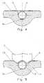
- This cavity 3is followed by a small footprint 4 extending on either side of the axis longitudinal of the device and whose role will be explained by the continuation then by a recess 5 whose section is in U-shaped (see Figure 4), intended to form a seat for receive a hypodermic needle 6. Then the section of the recess 5 increases to provide an elongated housing serving protection 7 for the part of the hypodermic needle 6 which is located outside the seat 5.
- the upper part 1b of the sheet 1has a cavity 8 symmetrical to cavity 3 and constituting the other tank wall for the dose of liquid medicine.
- the wall of this cavity 8has no ribs and can also be thinner than that of cavity 3, in particular when the two cavities 3 and 8 are produced from two separate sheets, so that when one pressure is exerted on the walls of these cavities 3, 8, only the wall of the cavity 8 deforms until it conforms to the shape of the cavity 3.
- this cavity 3 and that of the cavity 8are substantially symmetrical and chosen so that once the deformable wall of the cavity 8 is applied against it, this wall remains naturally in this deformed position and is thus bi-stable, being convex in one position and concave in the other position, so the reuse of the syringe is made impossible, thus avoiding any risk of contamination that would result.
- This cavity 8is followed by another cavity 9 substantially smaller, then by a wall 10 for closing of the seat 5 of the hypodermic needle 6 and finally by a wall 11 for closing the needle protection housing 7 6.
- Two projections 9aare formed inside the cavity 9. They have a profile complementary to that of the recess 4. Their role will be explained later.
- the part wall separating the cavity 8 from the upper part 1b of the cavity 9is shaped to reserve a communication passage 14 between the two cavities.
- a membrane waterproof 13is welded, so as to cover the entire area of the lower part 1a located between the communication passage 14 and the seat 5 of the needle 6, so as to form a tight separation between the tank formed between the walls of the cavities 3, 8 and the seat 5 of the needle 6, isolating the latter from the liquid contained in this reservoir and in the cavity 9 until the injection of this liquid.
- FIG 4illustrates the seat 5 and the needle 6 covered by the waterproof film 13, showing that the seal is not ensured between the film 13 and the needle 6.
- the figure 5shows the welding of the waterproof sheet 13 by a sonotrode S which causes the deformation of the film 13 and the creep of the thermoplastic from part 1a of the sheet 1 adjacent to seat 5, so as to surround the needle 6 tightly.
- the thermoplastic material sheet 1a subjected to the induced heating by the sonotrode Sfills the space between seat 5 and a dish 6a formed on the external face of the needle 6, of so as to anchor the needle to seat 5.
- a sonotrode S similar to that represented by Figure 4will be used to deform the closure wall 10 from seat 5 of hypodermic needle 6, so that deform this wall 10 to make it conform to the shape of the membrane 13, weld it to this membrane 13 and ensure thus sealing the seat 5 around the needle 6.
- a groove 15is formed between the cavities 3 and 8.
- a cutout 15ais provided in the center of the groove 15, on fold line 2, so that when the upper part 1b is folded over the lower part 1a around the fold line 2, an opening 16 appears allowing the reservoir formed to communicate between the cavities 3 and 8 with the outside.
- This opening 16serves to allow the introduction of a double tubular element line 17 in the tank.
- One of the conduits of this tubular element 17is connected to a suction source 18 intended to withdraw the air from the reservoir 3, 8, while the other line is connected to a source of liquid medication 19 which is drawn into the reservoir 3, 8 and into the volume formed between the membrane 13 and the second cavity 9, by the depression created by the aspiration of the source 18.
- the last operationis to weld parts 1a, 1b to the place of the opening 16 to seal the tank 3, 8.
- the actual injectionis done by pressing the walls 3, 8 of the reservoir until the liquid is completely expelled from this tank, after having introduced the needle at the desired location on the body of a patient or animal. After use, the device is intended to be discarded.
- the device describedcan be slightly modified so that it can be used to withdraw blood instead of injecting a dose of medicine.
- this deviceno longer has a membrane 13 or a cavity 9.
- the wall 8is shaped so as not to present only a stable position and not two, so as to return always in the position illustrated in figure 2. The rest of the device is the same as that described above.
- connection between the protection 6, 7 and the seat 5, 10 of the needle 6,we crush the wall 8 against the wall 3, we introduce the needle in the patient’s vein, and the pressure is released on the wall of the cavity 8 to allow it to return to the position illustrated in Figure 2 by drawing blood.
Landscapes
- Health & Medical Sciences (AREA)
- Life Sciences & Earth Sciences (AREA)
- Engineering & Computer Science (AREA)
- Public Health (AREA)
- Veterinary Medicine (AREA)
- Hematology (AREA)
- General Health & Medical Sciences (AREA)
- Animal Behavior & Ethology (AREA)
- Biomedical Technology (AREA)
- Heart & Thoracic Surgery (AREA)
- Physics & Mathematics (AREA)
- Molecular Biology (AREA)
- Surgery (AREA)
- Pathology (AREA)
- Biophysics (AREA)
- Medical Informatics (AREA)
- Manufacturing & Machinery (AREA)
- Diabetes (AREA)
- Vascular Medicine (AREA)
- Anesthesiology (AREA)
- Dermatology (AREA)
- Pain & Pain Management (AREA)
- Infusion, Injection, And Reservoir Apparatuses (AREA)
Abstract
Description
Translated fromFrenchLa présente invention se rapporte à un dispositif jetablepour le conditionnement et l'injection d'une dose de médicament,comprenant un corps creux dans lequel sont ménagésun réservoir souple et étanche en plastique, chimiquementinerte vis-à-vis de ce médicament et un siège de fixationd'une aiguille hypodermique, ainsi qu'à un procédé pour leconditionnement d'un médicament liquide dans un dispositifd'injection jetable. Elle se rapporte également à un dispositifjetable pour la prise de sang.The present invention relates to a disposable devicefor packaging and injecting a dose of medication,comprising a hollow body in which are formeda flexible and waterproof plastic tank, chemicallyinert to this drug and a fixation seata hypodermic needle, as well as a method forpackaging of a liquid medicine in a devicedisposable injection. It also relates to a devicedisposable for blood sampling.
La proportion de prises de sang et de médicaments injectésà très faibles volumes, typiquement entre 0,1 et 5 mlcroít constamment, en raison de la sensibilité de plus enplus grande des dispositifs d'analyse ainsi que de la plusgrande efficacité des médicaments injectés. Cette diminutionde volume permet d'envisager de changer le mode opératoireque nécessite les seringues classiques et qui consiste àfixer une aiguille hypodermique stérile sur la seringue et àremplir la seringue de la quantité de médicament à injecter.Le temps de transfert du liquide à injecter, du flacon dansla seringue qui est d'environ 20 secondes, le risque de sepiquer durant le remplissage de la seringue, le coût duflacon de médicament ainsi que celui des emballages de laseringue et de l'aiguille représentent une somme de frais etde dangers qui peuvent être évités.The proportion of blood tests and drugs injectedat very low volumes, typically between 0.1 and 5 mlconstantly growing, due to the increasing sensitivitylarger analysis devices as well as the morehigh effectiveness of the drugs injected. This decreasevolume allows to consider changing the operating modethat conventional syringes require and which consists ofattach a sterile hypodermic needle to the syringe andfill the syringe with the amount of medicine to inject.The transfer time of the liquid to be injected, from the vial intothe syringe which is about 20 seconds, the risk ofcost during the filling of the syringe, the cost ofmedicine bottle and the bottle of thesyringe and needle represent a fee andhazards that can be avoided.
On a déjà proposé depuis longtemps différentes solutionsde dispositifs permettant le conditionnement d'un médicamentliquide dans un réservoir souple en plastique chimiquementinerte auquel on fixe une aiguille hypodermiquequi est séparée du liquide à injecter par un joint ou unefermeture susceptible de se rompre lors de l'application d'une pression suffisante sur le réservoir souple, permettantla distribution du médicament à travers l'aiguille. Untel dispositif est décrit notamment dans le US 3'736'933.We have already proposed various solutions for a long timeof devices allowing the packaging of a drugliquid in a chemically plastic flexible tankinert to which a hypodermic needle is attachedwhich is separated from the liquid to be injected by a seal or aclosure likely to break during applicationsufficient pressure on the flexible tank, allowingdispensing the drug through the needle. Asuch a device is described in particular in US 3,736,933.
Ce dispositif ne comporte cependant pas de protectionde l'aiguille avant son utilisation, de sorte qu'un emballagede protection doit être prévu pour maintenir les aiguillesstériles jusqu'à leur utilisation.This device does not however include protectionof the needle before use, so that a packagingprotection must be provided to hold the needlessterile until used.
On a déjà prévu dans le US 4'130'117 une ampoule d'injectionmunie d'une aiguille, une fermeture susceptibled'être rompue séparant le contenu de l'ampoule de l'aiguilleet une coiffe soudée à l'ampoule protégeant l'aiguille jusqu'àson utilisation.In US 4'130'117, there is already an injection bulbfitted with a needle, a likely closureto be broken separating the contents of the ampoule from the needleand a cap welded to the bulb protecting the needle up toits use.
La production d'une telle ampoule doit être faite piècepar pièce. Aucune solution pour son remplissage n'est prévue,de sorte que la production d'un tel dispositif ne peutpas être obtenue sur des machines de conditionnement classiques,nécessitant le travail en continu à partir de matériauen bande, ou semi continu à partir de matériau en feuilledestiné à la formation de plusieurs dispositifs d'injectiondisposés côte à côte.The production of such a bulb must be done individuallyby piece. No solution for its filling is planned,so the production of such a device can onlynot be obtained on conventional packaging machines,requiring continuous work from materialstrip, or semi-continuous from sheet materialintended for the formation of several injection devicesarranged side by side.
La présente invention a pour but de remédier, au moinsen partie, aux inconvénients des solutions existantes.The object of the present invention is to remedy, at leastin part, to the disadvantages of existing solutions.
A cet effet, cette invention a pour objet un dispositifjetable pour le conditionnement et l'injection d'un médicamentselon la revendication 1. Elle a également pour objetun procédé pour le conditionnement d'un médicament liquidedans un dispositif d'injection jetable selon la revendication6. Elle a enfin pour objet un dispositif jetable pourprise de sang selon la revendication 7.To this end, the subject of this invention is a devicedisposable for packaging and injecting a drugaccording to
Par sa conception, ce dispositif comporte un logementde protection de l'aiguille hypodermique, permettant d'évitertout autre emballage pour assurer la stérilité de l'aiguille, ce qui constitue un gain de coût non négligeable,ainsi qu'une garantie quant à la stérilité du dispositif.By design, this device includes a housingprotection of the hypodermic needle, making it possible to avoidany other packaging to ensure the sterility of the needle,which constitutes a significant cost saving,as well as a guarantee as to the sterility of the device.
De préférence, une amorce de rupture est formée entrele siège de l'aiguille et le logement de protection de cetteaiguille, permettant une séparation aisée de la protectionde l'aiguille du reste du dispositif lors de son utilisation.Preferably, a rupture initiator is formed betweenthe needle seat and the protective housing of thisneedle, allowing easy separation of the protectionof the needle from the rest of the device when in use.
Avantageusement, le volume ménagé entre la seconde paroidéformable et la membrane étanche séparant le réservoirde liquide de l'aiguille hypodermique est au moins égal auvolume du conduit de cette aiguille, de sorte qu'en déformantla paroi déformable pour perforer la membrane, le liquidecontenu dans le volume ménagé entre la seconde paroidéformable et la membrane étanche remplit le volume de l'aiguillehypodermique. Grâce à cette disposition, la rupturede la membrane met simultanément et automatiquement le dispositifd'injection en condition d'utilisation. Celacorrespond à ce que fait le personnel médical avant touteinjection lorsqu'il pousse le piston d'une seringue pour enchasser l'air jusqu'à ce qu'une goutte de liquide sorte àl'extrémité de l'aiguille, sans le risque de perdre unepartie du médicament.Advantageously, the volume formed between the second walldeformable and the waterproof membrane separating the tankof fluid from the hypodermic needle is at least equal tovolume of the conduit of this needle, so that by deformingthe deformable wall to perforate the membrane, the liquidcontained in the volume formed between the second walldeformable and the waterproof membrane fills the volume of the needlehypodermic. Thanks to this arrangement, the breakof the membrane simultaneously and automatically puts the deviceinjection condition. itcorresponds to what medical personnel do above allinjection when he pushes the plunger of a syringe toexpel the air until a drop of liquid comes outthe tip of the needle, without the risk of losing apart of the drug.
Outre les avantages susmentionnés du dispositif de conditionnementet d'injection selon la présente invention, laconception de ce dispositif permet une fabrication et unconditionnement des doses de médicaments à l'aide d'installationsde conditionnement de types connus, à partir de matériauxen bandes, soit préalablement formés soit formés aucours du processus de conditionnement. Dans tous les cas lesprocédés de conditionnement utilisés sont habituels dans ledomaine du conditionnement de produits à usage médical, permettantdes cadences de production élevées dans les conditionsd'asepsie requises.In addition to the aforementioned advantages of the packaging deviceand injection according to the present invention, thedesign of this device allows manufacturing andpackaging of drug doses using facilitiespackaging of known types, from materialsin strips, either previously formed or trained induring the conditioning process. In all cases theconditioning processes used are usual in thefield of packaging of products for medical use, allowinghigh production rates under the conditionsasepsis required.
D'autres particularités et avantages du dispositif selonla présente invention apparaítront à la lumière de ladescription suivante qui sera faite à l'aide des dessins annexésqui illustrent, schématiquement et à titre d'exemple,une forme d'exécution du dispositif jetable pour le conditionnementet l'injection d'une dose de médicament, ainsiqu'un mode de mise en oeuvre du procédé de conditionnement,objets de la présente invention.
Le dispositif jetable pour le conditionnement et l'injectiond'une dose de médicament illustré par les figures 1et 2 résulte du pliage autour d'une ligne 2 (figure 3) et dusoudage de deux parties, inférieure 1a, supérieure 1b d'unefeuille 1, préalablement thermoformée, voire moulée par injection.En variante, les parties inférieure 1a et supérieure1b peuvent être deux éléments séparés soudés l'un àl'autre plûtot qu'un seul élément plié autour de la ligne 2.La matière de la feuille 1 peut être en COC (copolymèrecyclo-oléfine) ou un autre matériau thermoplastique inertevis-à-vis du médicament à conditionner.The disposable device for packaging and injectionof a dose of medication illustrated in Figures 1and 2 results from folding around a line 2 (Figure 3) andwelding of two parts, lower 1a, upper 1b of a
Le matériau en feuille 1 peut se présenter soit sousforme d'une bande continue, soit sous forme d'une feuillecontenant un nombre déterminé de doses à injecter, par exemple 10 ou 12, séparées les unes des autres par deslignes de pré-découpage 21. Lorsque l'on part de feuillesséparées contenant un certain nombre de doses, on peutavantageusement conformer ces feuilles par moulage parinjection plutôt que par thermoformage. Dans ce cas, il peutêtre avantageux de réaliser les parties inférieure 1a etsupérieure 1b sous forme de feuilles séparées. Dans le casd'une bande continue, celle-ci peut être séparée au fur et àmesure, entre des séries comportant un nombre désiré dedoses restant attachées les unes aux autres par les lignesde pré-découpage 21.The
Lorsqu'on part d'un matériau en bande, avant d'être repliéesl'une contre l'autre autour de la ligne de pliage 2,les parties inférieure 1a et supérieure 1b de la feuille 1sont thermoformées pour ménager, dans la partie inférieure1a une cavité 3 pour former au moins en partie un réservoirpour le médicament liquide à injecter. La paroi de cette cavité3 présente, de préférence, des nervures 3a destinées àla rendre plus rigide. Cette cavité 3 est suivie par unepetite empreinte 4 s'étendant de part et d'autre de l'axelongitudinal du dispositif et dont le rôle sera expliqué parla suite puis par un évidement 5 dont la section est enforme de U (voir figure 4), destiné à former un siège pourrecevoir une aiguille hypodermique 6. Ensuite, la section del'évidement 5 augmente pour ménager un logement allongé servantde protection 7 pour la partie de l'aiguille hypodermique6 qui est située à l'extérieur du siège 5.When starting from a strip material, before being foldedone against the other around the fold line 2,the lower parts 1a and upper 1b of the
La partie supérieure 1b de la feuille 1 présente unecavité 8 symétrique à la cavité 3 et constituant l'autreparoi du réservoir pour la dose de médicament liquide. Laparoi de cette cavité 8 ne présente pas de nervures et peutaussi être plus mince que celle de la cavité 3, notammentlorsque les deux cavités 3 et 8 sont réalisées à partir de deux feuilles distinctes, de manière à ce que, lorsqu'unepression est exercée sur les parois de ces cavités 3, 8,seule la paroi de la cavité 8 se déforme jusqu'à ce qu'elleépouse la forme de la cavité 3. La forme de cette cavité 3et celle de la cavité 8 sont sensiblement symétriques etchoisies pour qu'une fois que la paroi déformable de lacavité 8 est appliquée contre elle, cette paroi reste naturellementdans cette position déformée et est ainsi bi-stable,étant convexe dans une position et concave dans l'autreposition, de sorte que la réutilisation de la seringue estrendue impossible, ce qui évite ainsi tout risque de contaminationqui en résulterait.The
Cette cavité 8 est suivie par une autre cavité 9 sensiblementplus petite, puis par une paroi 10 pour la fermeturedu siège 5 de l'aiguille hypodermique 6 et enfin par une paroi11 de fermeture du logement de protection 7 de l'aiguille6. Deux saillies 9a sont formées à l'intérieur de lacavité 9. Elles ont un profil complémentaire à celui de l'évidement4. Leur rôle sera expliqué par la suite. La portionde paroi séparant la cavité 8 de la partie supérieure 1b dela cavité 9 est conformée pour réserver un passage de communication14 entre les deux cavités.This cavity 8 is followed by another cavity 9 substantiallysmaller, then by a
Comme on peut le voir sur la figure 2, une membraneétanche 13 est soudée, de manière à recouvrir toute la zonede la partie inférieure 1a située entre le passage de communication14 et le siège 5 de l'aiguille 6, de manière à formerune séparation étanche entre le réservoir formé entreles parois des cavités 3, 8 et le siège 5 de l'aiguille 6,isolant cette dernière du liquide contenu dans ce réservoiret dans la cavité 9 jusqu'à l'injection de ce liquide.As can be seen in Figure 2, a membranewaterproof 13 is welded, so as to cover the entire areaof the lower part 1a located between the communication passage14 and the
La figure 4 illustre le siège 5 et l'aiguille 6 recouvertspar le film étanche 13, montrant que l'étanchéitén'est pas assurée entre le film 13 et l'aiguille 6. La figure 5 montre le soudage de la feuille étanche 13 par une sonotrodeS qui provoque la déformation du film 13 et lefluage de la matière thermoplastique de la partie 1a de lafeuille 1 adjacente au siège 5, de manière à entourer l'aiguille6 de façon étanche. Simultanément, la matière thermoplastiquede la feuille 1a soumise à l'échauffement provoquépar la sonotrode S remplit l'espace situé entre le siège 5et un plat 6a formé sur la face externe de l'aiguille 6, demanière à assurer l'ancrage de l'aiguille au siège 5.Figure 4 illustrates the
Lors du soudage des deux parties 1a, 1b l'une contrel'autre, une sonotrode S similaire à celle représentée parla figure 4 sera utilisée pour déformer la paroi de fermeture10 du siège 5 de l'aiguille hypodermique 6, de manière àdéformer cette paroi 10 pour lui faire épouser la forme dela membrane 13, la souder à cette membrane 13 et assurerainsi l'étanchéité du siège 5 autour de l'aiguille 6.When welding the two
Comme illustré par la figure 3, lors du thermoformagede la feuille 1, une rainure 15 est ménagée entre les cavités3 et 8. Une découpe 15a est ménagée au centre de larainure 15, sur la ligne de pliage 2, de sorte que lorsquela partie supérieure 1b est pliée sur la partie inférieure1a autour de la ligne de pliage 2, une ouverture 16 apparaítpermettant de faire communiquer le réservoir formé entre lescavités 3 et 8 avec l'extérieur. Cette ouverture 16 sert àpermettre l'introduction d'un élément tubulaire à doubleconduit 17 dans le réservoir. L'un des conduits de cetélément tubulaire 17 est relié à une source d'aspiration 18destinée à retirer l'air du réservoir 3, 8, tandis quel'autre conduit est relié à une source de médicament liquide19 qui est aspiré dans le réservoir 3, 8 et dans le volumeménagé entre la membrane 13 et la seconde cavité 9, par ladépression créée par l'aspiration de la source 18. Ladernière opération consiste à souder les parties 1a, 1b à l'endroit de l'ouverture 16 pour fermer hermétiquement leréservoir 3, 8.As illustrated in Figure 3, during thermoformingof the
Avant le remplissage de ce réservoir, simultanément aupliage des deux parties 1a, 1b l'une sur l'autre autour dela ligne de pliage 2, on découpe dans les zones planes desdeux parties assemblées 1a, 1b de part et d'autre de l'extrémitéexterne du siège 5, à la jonction entre ce siège 5et le logement de protection 7 de l'aiguille 6, deux lignes20, formant un angle aigu en direction du réservoir 3, 8pour dégager l'extrémité avant de la seringue, comme illustréen particulier sur la figure 1. Ces deux lignes découpées20 forment une amorce de rupture entre la portion dudispositif contenant le logement de protection 7 et cellequi contient le réservoir (3, 8).Before filling this tank, simultaneously withfolding of the two
Lors de l'utilisation d'une dose de médicament, on sépareun dispositif contenant cette dose le long d'une lignede pré-découpage 21. On imprime ensuite une torsion entreles deux portions du dispositif de conditionnement et d'injectionsituées de part et d'autre des deux lignes découpées20, qui permettent de rompre facilement par cisaillement, lamatière qui relie la portion de ce dispositif comportant lelogement de protection 7 à celle qui comporte la dose demédicament, pour dégager l'aiguille hypodermique 6. Ensuite,une pression sur la cavité 9 permet de perforer la membrane13 à l'aide des saillies 9a. L'évidement 4 reçoit les saillies9a, de sorte que le liquide qui se trouvait dans la cavité9 est chassé dans le canal de l'aiguille 6. Le volumede la cavité 9 est choisi pour être légèrement supérieur àcelui du canal de l'aiguille 6, de sorte qu'une petite gouttede liquide perlera à l'extrémité de l'aiguille 6 une foisle liquide chassé hors de la cavité 9, montrant à l'utilisateurque le dispositif est prêt pour l'injection.When using a dose of medication, separatea device containing this dose along a linepre-cutting 21. We then print a twist betweenthe two portions of the packaging and injection devicelocated on either side of the two
L'injection proprement dite s'effectue en pressant surles parois 3, 8 du réservoir jusqu'à ce que le liquide soitcomplètement expulsé de ce réservoir, après avoir introduitl'aiguille à l'endroit désiré du corps d'un patient ou d'unanimal. Après utilisation, le dispositif est destiné à êtrejeté.The actual injection is done by pressingthe
Selon une variante, le dispositif décrit peut être légèrementmodifié pour pouvoir l'utiliser pour prélever dusang au lieu d'injecter une dose de médicament. A cet effet,ce dispositif ne comporte plus ni membrane 13, ni cavité 9.D'autre part, la paroi 8 est conformée pour ne présenterqu'une position stable et non deux, de manière à revenirtoujours dans la position illustrée par la figure 2. Lereste du dispositif est le même que celui décrit précédemment.According to a variant, the device described can be slightlymodified so that it can be used to withdrawblood instead of injecting a dose of medicine. To this end,this device no longer has a
Pour faire une prise de sang, on rompt la liaison entrela protection 6, 7 et le siège 5, 10 de l'aiguille 6, onécrase la paroi 8 contre la paroi 3, on introduit l'aiguilledans la veine du patient, et on relâche la pression sur laparoi de la cavité 8 pour lui permettre de revenir dans laposition illustrée par la figure 2 en aspirant du sang.To take a blood test, the connection betweenthe protection 6, 7 and the
Claims (7)
Translated fromFrenchPriority Applications (2)
| Application Number | Priority Date | Filing Date | Title |
|---|---|---|---|
| EP03405122AEP1452196A1 (en) | 2003-02-25 | 2003-02-25 | Device and method of making the package of medicament |
| PCT/CH2004/000097WO2004075955A1 (en) | 2003-02-25 | 2004-02-24 | Device and method for packaging a medicine and blood sample |
Applications Claiming Priority (1)
| Application Number | Priority Date | Filing Date | Title |
|---|---|---|---|
| EP03405122AEP1452196A1 (en) | 2003-02-25 | 2003-02-25 | Device and method of making the package of medicament |
Publications (1)
| Publication Number | Publication Date |
|---|---|
| EP1452196A1true EP1452196A1 (en) | 2004-09-01 |
Family
ID=32749028
Family Applications (1)
| Application Number | Title | Priority Date | Filing Date |
|---|---|---|---|
| EP03405122AWithdrawnEP1452196A1 (en) | 2003-02-25 | 2003-02-25 | Device and method of making the package of medicament |
Country Status (2)
| Country | Link |
|---|---|
| EP (1) | EP1452196A1 (en) |
| WO (1) | WO2004075955A1 (en) |
Cited By (3)
| Publication number | Priority date | Publication date | Assignee | Title |
|---|---|---|---|---|
| EP1983964A4 (en)* | 2006-02-16 | 2009-04-08 | Pka Softtouch Corp | DRUGS CHARGE DEVICE |
| EP2786774A1 (en)* | 2013-04-04 | 2014-10-08 | Flamina Holding AG | Disposable syringe |
| US11865321B2 (en) | 2016-12-15 | 2024-01-09 | Pka Softtouch Corp. | Fluid delivery device |
Families Citing this family (5)
| Publication number | Priority date | Publication date | Assignee | Title |
|---|---|---|---|---|
| ITBO20070166A1 (en)* | 2007-03-12 | 2008-09-13 | Gianpaolo Belloli | DEVICE FOR THE ADMINISTRATION OF A PRODUCT. |
| IL295010B1 (en) | 2015-03-10 | 2025-06-01 | Regeneron Pharma | Pollution-free piercing system and method |
| CN119950880A (en) | 2017-05-05 | 2025-05-09 | 里珍纳龙药品有限公司 | Auto-injectors and related methods of use |
| CN115361983A (en)* | 2020-04-05 | 2022-11-18 | 科斯卡家族有限公司 | Systems and methods for prefilled medical delivery devices |
| USD1007676S1 (en) | 2021-11-16 | 2023-12-12 | Regeneron Pharmaceuticals, Inc. | Wearable autoinjector |
Citations (4)
| Publication number | Priority date | Publication date | Assignee | Title |
|---|---|---|---|---|
| US2618263A (en)* | 1951-03-14 | 1952-11-18 | Sterling Drug Inc | Disposable single-use syringe |
| US4548601A (en)* | 1984-04-09 | 1985-10-22 | Lary Banning G | Prepackaged, injectable pharmaceutical and hypodermic needle combination |
| WO1989010765A2 (en)* | 1988-04-27 | 1989-11-16 | Morais Marcos Antonio Mendes | Discarded anesthesic applier through digital pressure |
| WO2003008021A1 (en)* | 2001-07-17 | 2003-01-30 | Bernd Hansen | Device for distributing substances |
- 2003
- 2003-02-25EPEP03405122Apatent/EP1452196A1/ennot_activeWithdrawn
- 2004
- 2004-02-24WOPCT/CH2004/000097patent/WO2004075955A1/enactiveApplication Filing
Patent Citations (4)
| Publication number | Priority date | Publication date | Assignee | Title |
|---|---|---|---|---|
| US2618263A (en)* | 1951-03-14 | 1952-11-18 | Sterling Drug Inc | Disposable single-use syringe |
| US4548601A (en)* | 1984-04-09 | 1985-10-22 | Lary Banning G | Prepackaged, injectable pharmaceutical and hypodermic needle combination |
| WO1989010765A2 (en)* | 1988-04-27 | 1989-11-16 | Morais Marcos Antonio Mendes | Discarded anesthesic applier through digital pressure |
| WO2003008021A1 (en)* | 2001-07-17 | 2003-01-30 | Bernd Hansen | Device for distributing substances |
Cited By (5)
| Publication number | Priority date | Publication date | Assignee | Title |
|---|---|---|---|---|
| EP1983964A4 (en)* | 2006-02-16 | 2009-04-08 | Pka Softtouch Corp | DRUGS CHARGE DEVICE |
| JP2009526575A (en)* | 2006-02-16 | 2009-07-23 | ピーケーエイ ソフトタッチ コーポレーション | Drug supply device |
| US8597257B2 (en) | 2006-02-16 | 2013-12-03 | Pka Softtouch Corp. | Drug delivery device |
| EP2786774A1 (en)* | 2013-04-04 | 2014-10-08 | Flamina Holding AG | Disposable syringe |
| US11865321B2 (en) | 2016-12-15 | 2024-01-09 | Pka Softtouch Corp. | Fluid delivery device |
Also Published As
| Publication number | Publication date |
|---|---|
| WO2004075955A1 (en) | 2004-09-10 |
Similar Documents
| Publication | Publication Date | Title |
|---|---|---|
| EP0403626B1 (en) | Storage and transfer bottle designed for storing two components of a medicamental substance | |
| EP1827353B1 (en) | Safety device for a bottle for medical use | |
| EP1079789B1 (en) | Ampoule containing a liquid for medical purposes | |
| FR2819174A1 (en) | AMPOULE FOR THE PACKAGING AND TRANSFER OF A LIQUID OR A POWDER FOR MEDICAL USE IN A CONTAINER | |
| EP0114145A2 (en) | Syringe for medical use | |
| LU88193A1 (en) | ADMINISTRATION DEVICE | |
| WO2019115974A1 (en) | Ready-to-use cryoresistant injection device | |
| EP0816252A1 (en) | Package for liquids having peelable film | |
| CA2875492A1 (en) | Injection assembly | |
| EP1034772B1 (en) | Device for transfering a substance contained in a vial to a pouch containing a solute | |
| EP1452196A1 (en) | Device and method of making the package of medicament | |
| EP3551253B1 (en) | Multi-dose dispenser | |
| EP0299991B1 (en) | Connecting device for an instrument for transferring liquid | |
| EP4251239A1 (en) | Pre-filled syringe (pfs) with twist-breakable tip, ensuring that the syringe is tamper-resistant and can be reliably opened | |
| FR2665633A1 (en) | Improvements to receptacles holding sterile contents, in particular to flexible bags for medical use | |
| EP1458326A2 (en) | Administration tip for a flexible bag for medical use | |
| EP1778564B1 (en) | Liquid container with a closing member | |
| EP1044670B1 (en) | Bag system with integrated safety means | |
| BE562703A (en) | ||
| EP3348249B1 (en) | Device for extemporaneous preparation of an amount of sterile fluid | |
| CA1315626C (en) | Connecting device for adapting an end part on a liquid transfer apparatus | |
| BE517434A (en) | ||
| CH660868A5 (en) | Mixer container with cartridge | |
| BE533912A (en) | ||
| CH502107A (en) | Hypodermic injection device needle holder |
Legal Events
| Date | Code | Title | Description |
|---|---|---|---|
| PUAI | Public reference made under article 153(3) epc to a published international application that has entered the european phase | Free format text:ORIGINAL CODE: 0009012 | |
| AK | Designated contracting states | Kind code of ref document:A1 Designated state(s):AT BE BG CH CY CZ DE DK EE ES FI FR GB GR HU IE IT LI LU MC NL PT SE SI SK TR | |
| AX | Request for extension of the european patent | Extension state:AL LT LV MK RO | |
| AKX | Designation fees paid | ||
| REG | Reference to a national code | Ref country code:DE Ref legal event code:8566 | |
| STAA | Information on the status of an ep patent application or granted ep patent | Free format text:STATUS: THE APPLICATION IS DEEMED TO BE WITHDRAWN | |
| 18D | Application deemed to be withdrawn | Effective date:20050302 |