EP1450899B1 - Disposable single-use external dosimeters for use in radiation therapies - Google Patents
Disposable single-use external dosimeters for use in radiation therapiesDownload PDFInfo
- Publication number
- EP1450899B1 EP1450899B1EP02784637.7AEP02784637AEP1450899B1EP 1450899 B1EP1450899 B1EP 1450899B1EP 02784637 AEP02784637 AEP 02784637AEP 1450899 B1EP1450899 B1EP 1450899B1
- Authority
- EP
- European Patent Office
- Prior art keywords
- patch
- sensor
- radiation
- patches
- patient
- Prior art date
- Legal status (The legal status is an assumption and is not a legal conclusion. Google has not performed a legal analysis and makes no representation as to the accuracy of the status listed.)
- Expired - Lifetime
Links
- 238000001959radiotherapyMethods0.000titleclaimsdescription12
- 230000005855radiationEffects0.000claimsdescription154
- 238000011282treatmentMethods0.000claimsdescription61
- 230000001070adhesive effectEffects0.000claimsdescription31
- 239000000853adhesiveSubstances0.000claimsdescription30
- 230000015654memoryEffects0.000claimsdescription29
- 239000000758substrateSubstances0.000claimsdescription28
- 239000000463materialSubstances0.000claimsdescription21
- 239000000523sampleSubstances0.000claimsdescription19
- 238000004590computer programMethods0.000claimsdescription18
- 238000003860storageMethods0.000claimsdescription17
- 206010028980NeoplasmDiseases0.000claimsdescription16
- 230000005055memory storageEffects0.000claimsdescription16
- 238000005259measurementMethods0.000claimsdescription14
- 238000012545processingMethods0.000claimsdescription11
- 230000035945sensitivityEffects0.000claimsdescription7
- 238000000034methodMethods0.000claimsdescription5
- 238000012544monitoring processMethods0.000claimsdescription5
- 230000001186cumulative effectEffects0.000claimsdescription4
- 239000002019doping agentSubstances0.000claimsdescription4
- 150000002500ionsChemical class0.000claimsdescription4
- 238000002560therapeutic procedureMethods0.000claimsdescription4
- 238000012546transferMethods0.000claimsdescription4
- 238000012790confirmationMethods0.000claimsdescription3
- 230000001225therapeutic effectEffects0.000claimsdescription3
- 238000011002quantificationMethods0.000claims1
- 238000010586diagramMethods0.000description13
- 238000004980dosimetryMethods0.000description12
- 206010073306Exposure to radiationDiseases0.000description9
- 230000000875corresponding effectEffects0.000description9
- 230000008859changeEffects0.000description8
- 230000003287optical effectEffects0.000description6
- 230000006870functionEffects0.000description5
- 239000004065semiconductorSubstances0.000description5
- 230000004044responseEffects0.000description4
- 239000004593EpoxySubstances0.000description3
- 239000011248coating agentSubstances0.000description3
- 238000000576coating methodMethods0.000description3
- 230000000694effectsEffects0.000description3
- 238000007667floatingMethods0.000description3
- 238000011065in-situ storageMethods0.000description3
- 238000003780insertionMethods0.000description3
- 230000037431insertionEffects0.000description3
- 238000004519manufacturing processMethods0.000description3
- 230000008569processEffects0.000description3
- 230000003068static effectEffects0.000description3
- 230000001954sterilising effectEffects0.000description3
- 238000004659sterilization and disinfectionMethods0.000description3
- 238000011088calibration curveMethods0.000description2
- 238000006243chemical reactionMethods0.000description2
- 238000004891communicationMethods0.000description2
- 238000004883computer applicationMethods0.000description2
- 239000007799corkSubstances0.000description2
- 230000008878couplingEffects0.000description2
- 238000010168coupling processMethods0.000description2
- 238000005859coupling reactionMethods0.000description2
- 238000011156evaluationMethods0.000description2
- 230000005669field effectEffects0.000description2
- 238000001727in vivoMethods0.000description2
- 239000000976inkSubstances0.000description2
- 239000012212insulatorSubstances0.000description2
- 239000002184metalSubstances0.000description2
- 239000003973paintSubstances0.000description2
- 239000011253protective coatingSubstances0.000description2
- 230000001681protective effectEffects0.000description2
- 238000009718spray depositionMethods0.000description2
- 238000012360testing methodMethods0.000description2
- 210000001685thyroid glandAnatomy0.000description2
- 238000012795verificationMethods0.000description2
- IAYPIBMASNFSPL-UHFFFAOYSA-NEthylene oxideChemical compoundC1CO1IAYPIBMASNFSPL-UHFFFAOYSA-N0.000description1
- WQZGKKKJIJFFOK-GASJEMHNSA-NGlucoseNatural productsOC[C@H]1OC(O)[C@H](O)[C@@H](O)[C@@H]1OWQZGKKKJIJFFOK-GASJEMHNSA-N0.000description1
- 231100000987absorbed doseToxicity0.000description1
- 230000004913activationEffects0.000description1
- 230000004888barrier functionEffects0.000description1
- 230000036760body temperatureEffects0.000description1
- 210000004556brainAnatomy0.000description1
- 238000004422calculation algorithmMethods0.000description1
- 201000011510cancerDiseases0.000description1
- 238000012512characterization methodMethods0.000description1
- 230000003749cleanlinessEffects0.000description1
- 229920001577copolymerPolymers0.000description1
- 230000002596correlated effectEffects0.000description1
- 238000013500data storageMethods0.000description1
- 230000002950deficientEffects0.000description1
- 231100000673dose–response relationshipToxicity0.000description1
- 238000005516engineering processMethods0.000description1
- 125000003700epoxy groupChemical group0.000description1
- 238000011067equilibrationMethods0.000description1
- 239000008103glucoseSubstances0.000description1
- 239000007943implantSubstances0.000description1
- 230000036512infertilityEffects0.000description1
- 239000003112inhibitorSubstances0.000description1
- 230000000977initiatory effectEffects0.000description1
- 238000005468ion implantationMethods0.000description1
- 238000010884ion-beam techniqueMethods0.000description1
- 230000005865ionizing radiationEffects0.000description1
- WABPQHHGFIMREM-UHFFFAOYSA-Nlead(0)Chemical compound[Pb]WABPQHHGFIMREM-UHFFFAOYSA-N0.000description1
- WABPQHHGFIMREM-BJUDXGSMSA-Nlead-206Chemical compound[206Pb]WABPQHHGFIMREM-BJUDXGSMSA-N0.000description1
- 239000004973liquid crystal related substanceSubstances0.000description1
- 210000004072lungAnatomy0.000description1
- 230000000873masking effectEffects0.000description1
- 229910044991metal oxideInorganic materials0.000description1
- 150000004706metal oxidesChemical class0.000description1
- 239000000203mixtureSubstances0.000description1
- 239000013307optical fiberSubstances0.000description1
- 210000000056organAnatomy0.000description1
- 238000004806packaging method and processMethods0.000description1
- 230000036961partial effectEffects0.000description1
- 229920002120photoresistant polymerPolymers0.000description1
- 229920001084poly(chloroprene)Polymers0.000description1
- 229920003223poly(pyromellitimide-1,4-diphenyl ether)Polymers0.000description1
- 229920000647polyepoxidePolymers0.000description1
- 229920000642polymerPolymers0.000description1
- 238000011158quantitative evaluationMethods0.000description1
- 230000000191radiation effectEffects0.000description1
- 230000002441reversible effectEffects0.000description1
- 238000011896sensitive detectionMethods0.000description1
- 238000000926separation methodMethods0.000description1
- 238000004088simulationMethods0.000description1
- 230000000007visual effectEffects0.000description1
Images


Classifications
- G—PHYSICS
- G01—MEASURING; TESTING
- G01T—MEASUREMENT OF NUCLEAR OR X-RADIATION
- G01T1/00—Measuring X-radiation, gamma radiation, corpuscular radiation, or cosmic radiation
- G01T1/02—Dosimeters
- G01T1/026—Semiconductor dose-rate meters
- A—HUMAN NECESSITIES
- A61—MEDICAL OR VETERINARY SCIENCE; HYGIENE
- A61N—ELECTROTHERAPY; MAGNETOTHERAPY; RADIATION THERAPY; ULTRASOUND THERAPY
- A61N5/00—Radiation therapy
- A61N5/10—X-ray therapy; Gamma-ray therapy; Particle-irradiation therapy
- A61N5/1048—Monitoring, verifying, controlling systems and methods
- A61N5/1071—Monitoring, verifying, controlling systems and methods for verifying the dose delivered by the treatment plan
- A61N2005/1072—Monitoring, verifying, controlling systems and methods for verifying the dose delivered by the treatment plan taking into account movement of the target
- A—HUMAN NECESSITIES
- A61—MEDICAL OR VETERINARY SCIENCE; HYGIENE
- A61N—ELECTROTHERAPY; MAGNETOTHERAPY; RADIATION THERAPY; ULTRASOUND THERAPY
- A61N5/00—Radiation therapy
- A61N5/10—X-ray therapy; Gamma-ray therapy; Particle-irradiation therapy
- A61N5/1048—Monitoring, verifying, controlling systems and methods
- A61N5/1071—Monitoring, verifying, controlling systems and methods for verifying the dose delivered by the treatment plan
Definitions
- the present inventiongenerally relates to the assessment or quantitative evaluation of the amount of radiation delivered to a patient undergoing radiation therapy.
- radiation therapyis delivered over a successive series of radiation treatment sessions.
- High-energy photons and/or electronsare carefully directed and/or focused from an ex vivo radiation source so that they travel into a targeted treatment area in a patient's body.
- the size, shape, and position of the treatment area(typically where a tumor is or was) as well as its anatomical location in the body and its proximity to sensitive normal tissues are considered when generating a particular patient's treatment plan. That is, the treatment is planned so as to deliver a suitably high dose of radiation to the tumor or targeted tissue while minimizing the dose to nearby sensitive tissue that typically cannot be completely avoided.
- Directing radiation into non-affected regionsmay produce undesired side effects particularly as it relates to tissue that may be sensitive to certain dosages of radiation.
- Conventional external or skin-mounted radiation dosimeter systemsuse semiconductor circuitry and lead wires that power/operate the dosimeters. These types of dosimeters are available from Scandatronics and/or IBA ("Ion Beam Applications") having an international headquarters location in Belgium. While these radiation dosimeter systems may provide radiation dose estimations, they can, unfortunately, be relatively expensive. Further, these types of dosimeters are used for a plurality of patients potentially raising sterility or cleanliness problems between patients. Conventional dosimeter systems may also require substantial technician time before and during the radiation session. For example, conventional dosimeter systems need to be calibrated before the radiation session may begin.
- the lead wirescan be cumbersome to connect to the patients and may require excessive set-up time as the technician has to connect the lead wires to run from the patient to the monitoring system and then store the lead wire bundle between patient treatment sessions. Therefore, technicians do not always take the time to use this type of system, and no confirmation estimate of the actual radiation delivered is obtained.
- thermo-luminescent detectorsOther radiation sensors include thermo-luminescent detectors (TLD's).
- TLD detectorsdo not require wires during operation, they are analyzed using a spectrophotometer (that may be located in an offsite laboratory) and are not conducive to real-time readings.
- US 5,444,254discloses a dosimeter patch according to the preamble of claims 1 and 2. It is an object of the present invention to provide a cost-effective surface mount radiation dosimeter that can be used to evaluate the radiation dose delivered to a patient undergoing radiation therapy.
- This memory storage devicemay be queried at any time in order to obtain a record of the dose applied to the patch.
- Other informationsuch as patient identification, time, date, hospital, therapist, state of the device, dosed/undosed and calibration data may be stored in the memory storage device.
- a disposable, single-use skin mounted radiation dosimeterthat has a self-contained package that is small, adhesively attachable to the skin of the patient, and operates in a relatively easy to operate and read manner without requiring the use of lead wires.
- an external use radiation dosimeter patchas described in claim 1.
- an external use radiation dosimeter patchas described in claim 2.
- the sensor patchmay be pre-dosed and/or calibrated before the sensor patch is secured to the patient.
- the obtained datamay be stored in an electronic storage device provided on the sensor patch itself.
- the storage devicemay be, for example, an EEPROM.
- Other informationsuch as the patient's name, the doctor's name, the test date and the like, may also be stored in the storage device provided on the sensor patch.
- the datacan be stored on a computer readable memory integrated on a physical record sheet that can be placed in the patient's file.
- a system for monitoring radiation administered to a patient during a therapeutic treatmentcomprises:
- the at least one dosimeter patchis a plurality of discrete sensor patches and the reader is configured to serially contact with each respective sensor patch to obtain the threshold voltage value associate therewith.
- a sheet of sensor patchesmay be pre-dosed and/or calibrated simultaneously or individually before the sensor patches are secured to the patient.
- the calibration and/or pre-dosingmay be performed at the original equipment manufacturer (OEM) or at the actual test site.
- the sheet of sensor patchesmay includes about 30 to about 100 sensors.
- the sensorsmay also be provided in a high density array of sensors where so many sensors are provided in a certain area of the high density array, for example, multiple sensors may be provided per square inch or per 3 by 3 inch regions of the high density array.
- kit of disposable single-use radiation dosimeter patchescomprising:
- the operational electronic componentmay be a radiation sensitive biased MOSFET or MOSFETs (such as MOSFET pairs) and the detectable operational parameter that changes can be the MOSFET threshold voltage(s).
- a medical grade adhesiveis supplied on the lower primary surface of the sensor body such that the sensor may be adhered to the patient's skin.
- an adhesive coverlaymay be provided over the body of the sensor to secure the sensor to the patient's skin.
- a computer program productfor evaluating a radiation dose delivered to a patient during a therapy session, the computer program product comprising:
- the computer program productcomprises a computer readable storage medium having computer readable program code embodied in the medium.
- the computer-readable program codecomprises: (a) computer readable program code for receiving pre-irradiation threshold voltage data associated with a plurality of disposable sensor patches; (b) computer readable program code for accepting data from a reader configured to electrically serially contact each of the plurality of disposable sensors for a short time; and (c) computer readable program code for determining the voltage threshold shift of the disposable sensor patches after radiation to determine the radiation exposure.
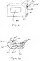
- Figure 1illustrates an example of a radiation system 10 with a radiation beam source 20 directed at a patient 50 having a tumor site.
- the patient 50can be positioned so as to be aligned and stationary with respect to the beam 20b (illustrated by the diverging dotted lines) during the treatment.
- the patient 50can be arranged in any desired position depending on the direction of the beam, the location of the tumor, and the type of radiation therapy system employed.
- the patientis reclined, substantially flat and face up on a table so that the beam 20b is directed into the targeted tumor site in the body as the patient undergoes radiation therapy in a treatment session.
- the patientwill undergo a plurality of successive treatment sessions over a treatment period.
- Each treatment sessionmay be planned to administer radiation doses of between about 1-2 Gray (100-200cGy) with an overall treatment limit of about 35-80 Gray.
- At least one disposable single-use dosimeter sensor patch 30can be positioned externally on the skin of the patient 50.
- single-useis used to refer to a use for a single patient during a treatment session.
- the sensor patch 30may be episodically worn or continuously worn. It will be understood that a treatment session may include an active radiotherapy administration during a single treatment session or serially spaced apart treatment sessions. The treatment session may have a duration of minutes, hours, days and the like. Furthermore, a calibration dose obtained before the sensor patch 30 is positioned on a patient is not to be considered the "single-use.”
- a plurality of sensor patches 30are located both on the front and back of the patient 50.
- the sensor patches 30are configured to change an operational parameter in a predictable manner that correlates to radiation dose it receives, as will be discussed further below.
- the sensor patch 30can be configured so as to be self-contained and discrete and devoid of dangling lead wires extending to a remote power source or operating system during use and in position on the patient.
- a readerfor example, reader 75 ( Figures 6 and 7 ), can be configured to obtain the data from the sensor patch 30 by, for example, electrically contacting with each sensor patch 30 of interest.
- the reference number "75"will be used to refer generally to a reader device according to embodiments of the present invention. Particular embodiments of a reader device 75 may be referred to using the reference number 75 and one or more primes attached thereto. For example, particular embodiments of the reader device may be denoted 75' or 75". This convention may similarly be used with respect to other features of the present invention. For example, the reference number "30"' will be used to refer to particular embodiments of a sensor patch herein. It will be understood that features discussed with respect to any embodiment of the present invention may be incorporated into other embodiments of the present invention even if these features are not discussed specifically with reference to each individual embodiment.
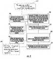
- At least one single-use disposable dosimeter sensor patchcan be releasably secured to the skin of the patient ( block 100 ).
- the sensor patchmay be calibrated and/or pre-dosed before being attached to the patient ( block 101 ).
- the calibration and/or pre-dosing of the sensor patchmay be done on an individual patch basis or many sensor patches may be calibrated and/or pre-dosed in batches simultaneously as discussed further below.
- the patch(es)can be conveniently attached to the patient in operation-ready condition before the patient enters the radiation treatment room or chamber ( block 102 ) to limit or reduce the set-up time required or the "down-time" of the equipment or the treatment room.
- the sensor patch or patchesmay be secured to the patient prior to his/her entry into the radiation treatment room.
- a pre-irradiation or pre-dose measurement or reading of data associated with an operational parameter of the sensor patch(es) 30can be obtained prior to initiation of the radiation treatment ( block 105 ).
- the datacan be obtained in situ, with the sensor patch(es) 30 in position on the patient.
- the pre-dose datacan be established prior to positioning the sensor patch(es) onto the subject as discussed above and the data then transferred to the reader or associated controller and/or computer at a desired time.
- the post-radiation readingcan be taken when the patient leaves the treatment room to evaluate the dose delivered during the treatment session to limit the amount of room-use time.
- the sensor patches 30can be removed from the patient and then read by a handheld portable or a bench top reader. The reading can be obtained while the sensor patches 30 remain on the patient. The reading may be able to be obtained in situ during the treatment session (without removing the sensor patch(es) from the patient) to provide real-time feedback to the clinician estimating whether the desired dose is being administered to the patient.
- the temperature of the sensor patch(such as at a location adjacent the circuitry) or of the subject (skin or core body) can also be ascertained or obtained and taken into account when calculating the radiation dose. In any event the dose reading can be obtained without requiring external powering or externally applied biasing of the sensor patches 30 during the radiation treatment.
- a plurality of discrete sensor patches 30can be positioned to cover a region on the skin that is in the radiation beam path so as to reside over the tumor site.
- One or more sensor patches 30can also be positioned in radiation sensitive areas of the body to confirm stray radiation is not unduly transmitted thereto.
- Figure 2illustrates that a sensor patch can be located at the neck over the thyroid when the tumor site is over the chest region.
- sensitive regionsinclude, but are not limited to, the thyroid, the spine, the heart, the lungs, the brain, and the like.
- radiationis administered to the patient in a first treatment session ( block 110 ).
- Data associated with a change in an operational parameter in the dosimeter sensor patch circuitrymay be obtained from the sensor patch using a reader device ( block 120 ) after administering the radiation to the patient ( block 110 ).
- a sensor patchmay be removed from the patient and inserted into the reader device to transfer the data from the sensor patch.
- the reader devicemay contact the sensor patch as discussed further below.
- the radiation dose received by the patientcan be determined based on the obtained data ( block 125 ).
- the obtained data as well as other informationmay be stored in a memory device included on the sensor patch as described further below ( block 130 ).
- the sensor patchdoes not require lead wires extending from a remote power source or computer system to operate.
- the sensor patch 30is configured to be a discrete patch (or a patch array of sensors) that can transmit or relay data upon contact with and/or insertion into a reader device 75 and may store data in an electronic memory device included on the sensor patch.
- the sensor patch 30may be configured to communicate wirelessly with the reader 75.
- the radiation dose received by the sensor patch 30can be determined and used to estimate the dose received by the patient during the radiation therapy session based on the data obtained by the reader.
- the readeritself can be a handheld portable unit that may or may not include wires to connect with a remote controller or computer as will be discussed further below.
- the operationscan be carried out for each or a selected radiation treatment session. If the operations are repeated for each treatment session, a cumulative amount of delivered radiation can be estimated/confirmed to allow a clinician to evaluate whether additional treatments are desired.
- Figure 3Aillustrates that the sensor patches 30 can be provided in a kit or set 130 including a plurality of sensors 30p.
- the plurality of sensors 30pmay be configured in sufficient numbers or types for a single patient or so as to be able to supply sensors across a plurality of patients.
- a strip of six sensor patches 30can be packaged together as a set 130' as shown in Figure 15A . It is contemplated that, depending on the treatment type, the treatment location, the tumor site, and the like, different numbers of sensor patches 30 may be used for different patients.
- the kit 130may include from about 2 to about 10 or more sensor patches 30 that can be selectively chosen for use by the clinician.
- Each sensor patch 30can be sterilized and sealed in a sterile package or the kit 130 itself can be sized and configured to hold a plurality of the sensor patches 30p in a sterile package that, once opened, can be either used or discarded.
- the sensor kit 130is sized for multi-patient use, then larger quantities may be packaged individually, or in sets within the multi-patient package, together.
- the sterilizationcan be performed by heat or chemical exposure, such as by ethylene oxide sterilization. In certain embodiments, sterilization and/or sterile packaging may not be required.
- each sensor patch 30can be packaged with pre-irradiation characterizing data 132.
- This data 132can be included in optically or electronically readable formats such as in bar code format for the reader to be able to read without having the clinician enter the information into a controller/computer.
- the data 132may be included in a memory storage device 67, for example, an electrically programmable memory such as an electrically erasable read only programmable memory (EEPROM), provided on each sensor patch 30p as discussed further below.
- the memory storage device 67may include information such as patient identification, time, date, hospital, therapist, state of the device, dosed/undosed sensor data and calibration data.
- the memory storage device 67may further be used to store bias parameters and/or information with respect to measurement methodology for each individual patch 30.
- Each sensor patch 30can have an individual calibration coefficient, dose data or characterizing data label located on the sensor patch 30 or as a corresponding label held with the package or kit 130.
- each sensor patch 30 produced in a common production run (off of the same wafer or chip) with substantially similar characterizing datamay be packaged together and a single calibration characterizing data or label 132 can be included with the set 130 or sets or production run.
- the calibration related characterizing datacan include the pre-irradiation threshold voltage value of a metal-oxide semiconductor field-effect transistor(s) (MOSFET(s)) that is measured at an OEM and provided in or with the sensor patch set 130.
- MOSFET(s)metal-oxide semiconductor field-effect transistor
- identifying indiciamay be disposed on the sensor patches 30 to allow a clinician to easily visually identify and/or account for the sensors used.
- Figure 3Aillustrates three discrete sensor patches labeled as 1F, 2F, and 3F as well as a sensor with a pictorial representation of a heart 4F (other visual images can also be used such as a yellow caution sign, other anatomical symbols, and the like).
- the heart or caution sensor patch 30scan be positioned in a radiation sensitive area to detect the amount of radiation delivered to that area.
- the radiation beamis adjusted to reduce the radiation exposure to sensitive areas and a caution-sensitive sensor patch 30s (or patches) can indicate whether adjustments need to be made to reduce the detected exposure for each or selected treatment sessions.
- the sensor patches 30s used for sensitive detectionmay be configured with increased sensitivity for enhanced dose resolution capability for measuring small, residual, or stray doses of radiation (such as those located over critical organs which are not in the treatment volume).
- the circuit 30c ( Figure 9A ) for the high sensitivity sensor 30sincludes at least one radiation-sensitive field-effect transistor (RADFET) that can be configured to produce a larger threshold voltage shift for a given amount of received or absorbed dose relative to the sensors 30 positioned in the window of the targeted treatment volume.
- the larger voltage shiftmay increase dose resolution and possibly dose repeatability.
- single-use dosimeterscan be optimized to work over a much lower dose range than multiple use dosimeters. Since the typical per day fraction for radiation therapy is about 200 cGy, the dosimeter sensor 30 can be optimized for accuracy and repeatability over this dose range. A 50-500 cGy operating range should meet performance goals while providing adequate flexibility for varying treatment plans. A multiple-session fraction dosimeter sensor 30 may require a much larger dose range that depends on the number of fractions over which the sensor will operate.
- "disposable"means that the sensor patch is not reusable and can be disposed of or placed in the patient's records.
- the indiciacan include an alphanumeric identifier such as the letter "F" located to be externally visible on the sensor patches 30.
- the letter "F”can represent that the sensors are placed on a first side or front of the patient.
- Figure 3Billustrates that a second set of sensors 130' can be supplied, these sensor patches 30 can be labeled with different indicia, such as 1B, 2B, 3B and the like, representing that they are located at a different location relative to the first set (such as a second side or back of the patient).
- Using data from opposing outer surfacescan allow an interpolated radiation dose amount to be established for the internal tumor site.
- indicia described abovenamely “F” and “B” are provided herein for exemplary purposes only and that indicia according to embodiments of the present invention are not limited by the examples provided. Any label, mark, color or the like may be used that would serve to distinguish one patch or set of patches from another patch or set of patches without departing from the teachings of the present invention.
- the first set of patches 130may be blue and the second set of patches 130' may be red.
- the indiciamay be, for example, on the sensor patch itself or on an adhesive covering placed on or over the sensor patch without departing from the teachings of the present invention.
- Figure 3Cillustrates a patient anatomical map 150 that can be used to identify where each of the sensor patches 30 are placed on the body of the patient.
- the map 150may be stored in the patient chart or file.
- the cliniciancan allocate the same sensor patch identifier ("A", "1F", etc...) to the same location.
- the map 150 and/or indicia on the sensor patches 30can, in turn, help the clinician consistently identify whether a particular location may have undue or deficient exposure. For example, if sensor patch F1 indicates a low radiation exposure, while F3 indicates a relatively high exposure, and the two are positioned in the targeted beam region, either one or both of the sensor patches 30 is not functioning properly, or the radiation beam may need adjustment.
- Using substantially the same sensor patch position for successive treatment sessionsmay allow cumulative radiation dose data to be obtained and correlated to provide a more reliable indication of dose.
- the clinicianmay also draw markings on the patient's skin to help align the sensor patches 30 in relation thereto over the different treatments sessions.
- the discrete sensor patches 30can be arranged to reside on a common substrate or to be attached to each other so as to define known or constant distances therebetween (not shown).
- the sensor patches 30may be configured to be at the body temperature of the patient during use or at room temperature, or temperatures in between.
- a temperature readingmay be obtained, assumed, or estimated.
- the temperaturemay impact the operational change if substantially different from that upon which the calibration data is established.
- a first set-up pre-dose verification protocolcan be carried out to deliver a first radiation dose and a first radiation dose value can be obtained for at least one selected patch to confirm that the radiation beam focus location is correct or suitable (or whether a sensitive area is receiving radiation).
- the systemcan be configured to map a dose gradient by correlating the determined radiation dose values at each patch location to the anatomical location on the subject of each patch.
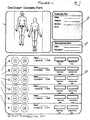
- Figure 4illustrates an exemplary patient dosimetry form 99, which may be, for example, a paper sheet or computer printable document.
- the form 99can contain an anatomical map 150 as discussed above with respect to Figure 3C .
- Sicel Technologies, Inc.asserts copyright protection for the form illustrated in Figure 4 and has no objection to reproduction of the patent document, as it appears in the Patent and Trademark Office patent file or records, but reserves all other rights whatsoever.
- the map 150may be used to identify and/or memorialize for the patient record where each of the sensor patches 30 are placed on the body of the patient during use.
- An anatomical map 150can be used to record the specifics of each radiation session and may be placed in each patient's chart or file to assist the doctor and/or clinician.
- Patients being treated on an ongoing basismay have multiple dosimetry forms 99 in their chart and/or file corresponding to each treatment session.
- the cliniciancan, as desired, allocate the same sensor patch identifier to the same location aided by the map 150.
- the dosimetry form 99may further include a dosimetry plan portion 152, a measurement data portion 154 and a sensor patch record portion 156.
- the dosimetry plan portion 152may include the patient's name, the date or dates the patient is scheduled for the treatment, the patient's doctor, and any information that may be specific to the patient or the patient's treatment.
- the measurement data portion 154may include information such as the date of the treatment and the therapist administering the treatment on that date.
- the sensor patch record portion 156may include labeled sections 158 (A, B,..) giving each patient a discrete identifier which may correspond to sensor patch locations (A, B,...) with the identifiers indicated on the anatomical map 150.
- the sensor patch record portion 156may further include dosing data, for example, target and measured doses as illustrated in Figure 4 .
- the sensor patch record portion 156may further include the actual sensor patch used on the patient in each of the labeled sections 158.
- the form 99can include two separate storage regions, namely a pre and post dose use storage region.
- the form 99can also allow a clinician to indicate whether the sensor patch was held in the entrance and/or exit field.
- the sensor patch 30may contain a storage or memory device 67 ( Figures 3A , 9B ), the storage or memory device on the sensor patches may be accessed to determine dosing information etc. if this information fails to be recorded, is misplaced or requires verification.
- the memory device 67 included on the sensor patch 30may further include the data recorded in the map portion 150, the dosimetry plan portion 152 and the measurement data portion 154 of the dosimetry form 99. Accordingly, the memory device 67 on the sensor patch 30 may serve as an electronic dosimetry patient record form. It will be understood that the dosimetry form 99 of Figure 4 is provided for exemplary purposes only and that it is possible to provide data and/or hold sensor patches in alternate manners.
- Figure 5Aillustrates the use of five primary sensor patches 30 positioned over the targeted treatment region (on the front side of the patient) and one sensor patch 30s positioned over the heart.
- Figure 5Billustrates three primary sensors 30 located over the back surface proximate the area corresponding to the underlying tumor site 25.
- Figure 6illustrates a reader or data acquisition device 75' in point contact with the underlying sensor patch 30 in order to detect the amount of radiation that the sensor patch 30 was exposed to during (or after) the treatment session.
- the sensor patch(es) 30can be secured to a patient's chart or dosimetry form 150 and read after removal from the patient.
- the reader 75' illustrated in Figure 6may be configured to contact a portion of an electrical circuit on the sensor patch 30 that includes a device that has an operating characteristic or parameter that changes upon exposure to radiation in a predictable manner to allow radiation doses to be determined.
- the reader 75'can be configured with a probe 75p that is configured to electrically contact an electrically conductive probe region on the sensor patch 30 so as to obtain a reading in a "short" time of under about 30 seconds, and typically in less than about 5-10 seconds, for each of the sensor patches 30.
- a sensor patch 30' disposed in a reader or data acquisition device 75"may be adapted to be inserted into the reader 75".
- the reader 75"is adapted to receive the sensor patch 30'.
- the sensor patch 30'is formed to include a tab portion 36 that at least a portion of is sufficiently rigid to sustain its shape for proper electrical coupling when inserted into a port 32 in the reader device 75".
- the reader 75"may include a sensor port 32 and the sensor patch 30' may be inserted into the port 32 in the reader 75" in order to detect the amount of radiation that the sensor patch 30' was exposed to.
- the port 32can read the sensor patch 30 as it is held in selected orientations in the port 32.
- the port 32may be configured similar to conventional devices that read, for example, glucose strip sensors and the like.
- the port 32 illustrated in Figure 7may contain one or more electrical contacts configured to contact one or more electrical contacts on the sensor patch 30' to electrically connect the reader 75" to an electrical circuit on the sensor patch 30'.
- the electrical circuit on the sensor patch 30'includes a radiation-sensitive component that has an operating characteristic or parameter that changes upon exposure to radiation in a predictable manner to allow radiation doses to be determined.
- the reader 75"may obtain a reading in under about 30 seconds, and typically in less than about 5-10 seconds, for each of the sensor patches 30.
- the reader device 75"can be held in a portable housing 37. It may be pocket sized and battery powered. In certain embodiments, the reader device 75 may be rechargeable. As shown in Figures 7 , 15A and 15B , the reader 75 may include a display portion 75d, for example, a liquid crystal display (LCD), to provide an interface to depict data to the doctor and/or technician.
- a display portion 75dfor example, a liquid crystal display (LCD), to provide an interface to depict data to the doctor and/or technician.
- LCDliquid crystal display
- the function of the reader device 75may be incorporated into any portable device adapted to receive a sensor patch 30 in, for example, a sensor port 32.
- the reader 75 functionality/circuitrycould be disposed in a personal digital assistant (PDA) that is adapted to include a radiation sensor port 32.
- PDApersonal digital assistant
- the reader 75may further include a remote computer port 33.
- the port 33may be, for example, RS 232, infrared data association (IrDA) or universal serial bus (USB), and may be used to download radiation and/or other selected data from the sensor patch 30 to a computer application or remote computer.
- the sensor patch 30 and the reader device 75may both be equipped with an RF interface and information may be shared between them wirelessly.
- the sensor patch 30includes a storage or memory device 67.
- the reader 75may be configured to obtain data stored in the memory device 67 of the sensor patch 30 using, for example, electrical contacts on the reader 75 and the patch 30, to transfer the data stored in the memory device 67 of the sensor patch 30.
- This data obtained from the sensor patch memory device 67may, for example, be stored locally on the reader 75 or be downloaded to an application on, for example, a remote computer using a port 33 provided in the reader 75.
- the memory device 67 on the sensor patch 30may serve as a permanent record of the radiation dose and may contain a real time clock such that the obtained data may include a time and date stamp.
- Figure 8Aillustrates exemplary embodiments of a sensor patch 30.
- the sensor patch 30includes a substrate layer 60, a circuit layer 61, and an upper layer 62 that may be defined by a coating, film, or coverlay material.
- the substrate layer 60can be selected such that it is resilient, compliant, or substantially conformable to the skin of the patient. Examples of suitable substrate layer materials include, but are not limited to, Kapton, neoprene, polymers, co-polymers, blends and derivatives thereof, and the like.
- the underside or bottom of the sensor patch 30bmay include a releasable adhesive 30a so as to be able to attach to the skin of the patient.
- the adhesive 30acan be a medical grade releasable adhesive to allow the sensor patch 30 to be secured to the skin during the treatment session and then easily removed without harming the skin.
- the adhesive 30acan be applied to portions, or all, of the bottom surface of the substrate layer 60.
- the underside of the sensor patch 30bmay be free of the adhesive.
- an adhesive coverlay 30cl( Figure 9C ) may be placed over the body of the sensor patch 30 to secure the sensor patch 30 to the patient.
- the adhesive coverlay 30clmay be sized to extend beyond the outer perimeter of the sensor substrate 60.
- the adhesivemay be on a portion or all of the underside of the coverlay 30cl .
- the sensor patch(es) 30is configured as a discrete, low profile, compact non-invasive and minimally obtrusive device that conforms to the skin of the patient.
- the sensor patch(es)may be less from about 0.25 to about 1.5 inches long and wide and have a thin thickness of from about 1 to about 5 mm or less.
- the sensor patches 30can be secured to the patient and allowed to reside thereon for a plurality or all of the successive treatments.
- the sensor patches 30can be configured to reside on the patient in its desired position for a 1-4 week, and typically about a 1-2 week period. In this manner, the same sensor patches 30 can be used to track cumulative doses (as well as the dose at each treatment session).
- An adhesivemay be applied in a quantity and type so as to be sufficiently strong to withstand normal life functions (showers, etc.) during this time.
- selected ones of the sensor patches 30can also be replaced as desired over the course of treatment as needed or desired. It may be important to attach the sensor patch 30 to the patient so that it makes and retains snug contact with the patient's skin. Air gaps between the sensor 30 and the patient's skin may cause complications with respect to obtaining the estimated dosage data.
- some embodiments of the present inventioninclude the placement of an overlay material 30fl over the sensor patch 30 to, for example, simulate placement of the sensor patch 30 beneath the patient's skin.
- This type of simulationmay help to focus a narrow portion of the radiation beam in proximity to the sensor patch 30 and, therefore, increase the reliability of radiation measurement.
- Radiation measurement using the sensor subsurface electronicsmay be optimal at from about .5 to about 3 cm beneath the patient's skin, but typically is from about 1 to about 1.5 cm beneath the patient's skin.
- the overlay material 30flmay be from about .5 to about 3 cm thick to simulate subsurface depth measurement conditions. The presence of this overlay material 30fl may decrease the influence of air gaps between the sensor 30 and the patient's skin.
- the overlay material 30flmay be, for example, a resilient flubber like or flexible material that will conform to the skin such as an elastomeric or the like. As illustrated in Figure 9D , the overlay material 30fl may be placed between the adhesive coverlay 30cl and the sensor patch 30 such that the adhesive coverlay 30cl adheres the sensor patch 30 and the overlay material 30fl to the patient's skin. As illustrated in Figure 9E , the overlay material 30fl may be placed over the adhesive coverlay 30cl and the sensor patch 30. In certain embodiments, the overlay material may have adhesive properties such that the overlay 30fl may be adhered to the patient's skin. The overlay material 30fl may also be integrated with the sensor patch 30 without departing from the teachings of the present invention.
- the sensor circuit layer 61can be attached to, and/or formed on, the underlying substrate layer 60.
- the upper layer 62can be configured as a moisture inhibitor or barrier layer that can be applied over all, or selected portions of, the underlying circuit layer 61. It is noted that, as shown, the thickness of the layers 60-62 are exaggerated for clarity and shown as the same relative thickness, however the thickness of the layers may vary.
- the sensor patch 30is configured as a low profile, thin device that, when viewed from the side, is substantially planar.
- Figure 8Bis a top view of embodiments of a sensor patch 30.
- the circuitmay layer include two conductive probe contacting regions 30p.
- the probe contacting regions 30pare configured to provide the connections between the operating circuitry on the circuit layer 61 and the external reader.
- the probe contacting region(s) 30pcan be directly accessible or covered with a protective upper layer 62. If directly accessible, during operation, the reader 75 can merely press against, contact or clip to the sensor patch 30 to contact the exposed surface of the conductive probe region 30p to obtain the reading.
- an upper layer 62that is a protective coating or other non-conductive insulator material, the clinician may need to form an opening into the coating or upper layer over the region 30p so as to be able to penetrate into the sensor patch 30' a certain depth to make electrical contact between the probe region 30p and the probe of the reader 75p.
- Figure 8Cillustrates a probe portion 75p of the reader 75' of Figure 6 .
- the probe portion 75pmay be configured so that the probe 75p includes, for example, conductive calipers, pinchers, or other piercing means, that can penetrate to make electrical contact with the probe contacting region 30p of the sensor patch.
- Figure 9Aillustrates a top view of embodiments of a circuit layer 61.
- the circuit layer 61includes the radiation sensitive operative sensor patch circuitry 30c that is self-contained and devoid of outwardly extending or hanging lead wires that connects to an operational member.
- the sensor patch circuitry 30cincludes a radiation sensitive device 63 that exhibits a detectable operational change when exposed to radiation.
- the radiation sensitive device 63is a miniaturized semiconductor component such as a MOSFET. Suitable MOSFETs include RADFETs available from NMRC of Cork, Ireland.
- the MOSFETmay be sized and configured to be about 1-2mm in width and length.
- the circuitry 30calso includes at least one conductive lead or trace 64 extending from the radiation sensitive device 63 to the conductive probe contacting region 30p.
- the conductive probe contacting region 30pis an annular ring.
- the traces or leads 64'may be formed, placed, or deposited onto the substrate layer 60 in any suitable manner including, but not limited to, applying conductive ink or paint or metal spray deposition on the surface thereof in a suitable metallic pattern, or using wires.
- an upper layer 62such as described above (such as epoxy) may be formed over the circuit layer 61 (or even the entire sensor patch).
- the sensor patch 30may include integrated Electro Static Discharge (ESD) protection, the reader 75 may include ESD protection components, or the user/operator may use ESD straps and the like during readings.
- ESDElectro Static Discharge
- the sensor patch 30 and circuit 30ccan be configured with two or more MOSFETS.
- onemay be positioned over the other on opposing sides of the substrate in face-to-face alignment to inhibit orientation influence of the substrate. (not shown).
- other materialse.g ., certain epoxies, can be used to both encapsulate the MOSFETs and provide further scattering influence to facilitate isotropic response of the MOSFETs.
- the backscatter effectcan be taken into account when calculating an entrance or exit dose or sufficient build-up may be provided on the top of the dosimeter to promote the equilibration of scattered electrons.
- Figure 9Bis a top view of further embodiments of a sensor patch 30' that includes a tab portion 36 that is adapted to be received by a reader, for example, reader 75" illustrated in Figure 7 .
- the circuit 30c'includes a circuit layer 61 that includes at least one electrical contact 31 shown as a plurality of substantially parallel leads.
- the sensor patch 30'is inserted into the reader port 32 of the reader 75" ( Figure 7 ) and the at least one electrical contact 31 is configured to provide the electrical connections between the operating circuitry on the circuit layer 61 and the external reader 75".
- the electrical contact(s) 31may be covered with a protective upper layer 62 ( Figure 8A ).
- an upper layer 62that is a protective coating or other non-conductive insulator material, the clinician may need to form an opening into the coating or upper layer over the electrical contact(s) 31 so these contact(s) 31 may make electrical contact with the reader via sensor port 32 ( Figure 7 ).
- Figure 9Bfurther illustrates the circuit layer 61 that includes the radiation sensitive operative sensor patch circuitry 30c'.
- the sensor patch circuitry 30c'includes a radiation sensitive device 63 that exhibits a detectable operational change when exposed to radiation and may include a memory device 67.
- the radiation sensitive device 63is a miniaturized semiconductor component such as a MOSFET. Suitable MOSFETs include RADFETs available from NMRC of Cork, Ireland. In certain embodiments, the MOSFET may be sized and configured to be about 1-2mm in width and length.
- the circuitry 30c'also includes at least one conductive lead or trace 64' extending from the radiation sensitive device 63 and/or the memory device 67 to the at least one electrical contact(s) 31.
- the traces or leads 64'may be formed, placed, or deposited onto the substrate layer 60 in any suitable manner including, but not limited to, applying conductive ink or paint or metal spray deposition on the surface thereof in a suitable metallic pattern, or using wires.
- an upper layer 62such as described above (such as epoxy) may be formed over the circuit layer 61 (or even the entire sensor patch).
- Each sensor patch 30may be from about 0.25 to about 1.5 inches long and wide and have a thin thickness of from about 1 to about 5 mm or less.
- the underside or bottom of the sensor patch 30bincludes a releasable adhesive 30a so as to be able to attach to the skin of the patient.
- the adhesive 30acan be a medical grade releasable adhesive to allow the sensor patch 30 to be secured to the skin during the treatment session and then easily removed without harming the skin.
- the adhesive 30acan be applied to portions, or all, of the bottom surface of the substrate layer 60.
- the underside of the sensor patch 30bmay be free of the adhesive.
- an adhesive coverlay 30clmay be placed over the entire body of the sensor patch 30 to secure the sensor patch 30 to the patient.
- the adhesive coverlay 30clmay be sized to extend beyond the outer perimeter of the sensor substrate 60 and leave the tab portion 36 of the sensor 30' exposed.
- the adhesive provided on the underside of the coverlay 30clmay be provided on a portion of the coverlay 30cl, for example, the portion of the coverlay 30cl contacting the patient's skin outside the perimeter of the sensor substrate 60, or on the entire underside of the coverlay 30cl.
- Sensor patches 30may be provided individually or in sheets containing multiple sensor patches 30.
- the sensor patches 30may be fabricated in high-density sheets.
- high densityrefers to multiple sensor patches provided on a unitary sheet. High density is intended to encompass very large sheets containing, for example, hundreds or thousands of sensors, as well as, for example, 3 X 3 regions of these very large sheets typically including 6 or more sensors per region.
- Providing the sensor patches 30 including memory devices 67, for example EEPROMs, on high density sheets 200 as illustrated in Figures 10A and 10Bprovide the capability of calibrating and/or pre-dosing the entire sheet of sensor patches 30 at one time.
- the sheets 200may include perforations for subsequent separation of the individual sensor patches 30 from the high density sheet 200.
- the sheet of sensor patches 200may include from about 30 to about 100 sensor patches 30 per sheet.
- multiple patches 30may be provided per square inch of the high density sheet 200 and/or multiple patches 30, typically at least 6 patches, may be provided in a 3 by 3 inch region of the high density sheet.
- the sensor patches 30may be calibrated at the factory or OEM. Each of the sensor patches 30 or the entire sheet 200 of sensor patches 30 may be calibrated by providing a wire(s) 205 illustrated in Figure 10B that electrically couples each of the sensor patches 30 on the sheet 200. For ease of reference, only a single electrical line to one sensor is shown on Figure 10B .
- the calibration datamay be provided to the sensor patches 30 through the wire(s) 205 and may be stored in the memory storage device 67 of the sensor patch 30.
- the ability to calibrate a plurality of sensor patches 30 simultaneouslymay provide more precision in the dosimetry process and, therefore, possibly more reliable results.
- the sensor patches 30may each have a dedicated wire or the sheet can have a calibration line all connected to a common lead 206 as shown in Figure 10e that may be used to calibrate and/or pre-dose the sensor patches 30 individually.
- the sensor patches 30may be pre-dosed, i.e. dosed prior to placement on the patient.
- Dosing a sensor patchmay include, for example, setting the amount of radiation to be delivered to a patient and the particular region(s) on the patient to which the radiation should be delivered. This process is typically performed by a physicist and can be very time consuming.
- the possibility of accurately pre-dosing a sensor patch 30may significantly reduce the need for a physicist to be involved in the dosimetry confirmation process. In other words, using reliable dose patches can reduce the time a physicist expends to confirm the treatment beam and path dose.
- sensor patches 30 adapted to be received by a reader 75are not limited to the configuration illustrated in the figures provided herein. These figures are provided for exemplary purposes only and are not meant to limit the present invention.
- the sensor patch 30' of Figure 9Bcan be configured with a geometry that allows it (entirely or partially) to be received by a reader 75".
- the insertable geometrymay take the form of an elongated tab, one end of the tab containing the radiation sensitive circuitry as well as the memory and the other end of the tab containing the electrical contacts for insertion into the reader device (not shown).
- the radiation sensitive device 63is a RADFET.
- the RADFETcan be biased with a gate/drain short so that it acts as a two-terminal device.
- Figure 11illustrates a portion of the circuit 30c with a RADFET 63 and two associated reader 75 interface or contact points 63I 1 , 63I 2 .
- Figure 12Aillustrates a reader 75 (upper broken line box) and the circuit 30c (lower broken line box) with the RADFET 63 configured with a gate to drain short.
- the reader 75can include a RADFET bias circuit 75b that includes a controlled current source to allow a voltage reading to be obtained corresponding to the threshold voltage of the RADFET.
- FIG. 12Billustrates a radiation response of a standard P210W2 400nm implanted gate oxide RADFET with lines for 0V (the -0- marked line) and 5V (the line with the -*- markings) irradiation bias responses.
- Vththreshold voltage
- the Vth valuezero dose
- the calibration curvecan be pre-loaded into the controller of the reader or a computer to provide the dose data.
- the clinicianmay wear grounding straps to reduce static sensitivity of the circuitry.
- ESD protectionmay be integrated into the sensor patch 30 itself.
- the Vth changecan be measured by determining the change in applied gate voltage necessary to induce a set current flow.
- the RADFET characterization datacan be obtained prior to exposure to radiation (zero dose).
- the starting threshold voltage of the sensor patch 30will be known from a priori information (or can be obtained by the clinician prior to placing on the patient or after on the patient but before radiation exposure) and can be placed in the reader 75 or computer associated or in communication therewith.
- Figure 13illustrates the threshold voltage relationship between output voltage (voltage) and current Ids (the electrical current, drain-to source, in microamps) as measured using the output voltage of the reader circuit shown in Figure 12A .
- the reader circuitis configured to contact the sensor to provide a constant current source to the circuit so as to be able measure Vth at a substantially constant or fixed bias condition.
- FIGs 14A and 14Billustrate alternate examples of MOSFET based circuits 30c.
- Each circuit 30cemploys a RADFET pair 63p ( Figure 14A ), 63p' ( Figure 14B ) as the radiation sensitive device 63.
- the configuration on the left of each of these figuresillustrates the irradiation configuration and the configuration on the right illustrates the read dose configuration.
- the RADFET pair 63pare differentially biased during irradiation to create different voltage offsets.
- Each of the RADFETs in the pair 63p 1 , 63p 2can be differentially biased during radiation to generate different voltage offsets when exposed to radiation.
- Using a pair of RADFETScan reduce the influence of temperature in the detected voltage shift value.
- the RADFET paircan be matched (such as taken from the same part of the substrate during fabrication) to reduce drift effects (Vth drift).
- the voltage readingcan be obtained with a zero bias state, and/or without requiring wires during radiation, and/or without requiring a floating gate structure.
- one of the RADFETs 63p 1 ' in the pair 63pis selectively implanted with dopant ions to shift the threshold voltage (Vth) of that RADFET with respect to the other RADFET 63p 2 '.
- the ion implantationcan be carried out in various manners as known to those of skill in the art, such as by masking one of the FETs with photoresist to inhibit ions from entering into the gate region.
- using the proper implant species and/or dopant materialcan increase the FET sensitivity to radiation effects.
- a MOSFET (RADFET) pairis used to effectively provide "differential biasing" without the need to apply an external voltage and without the need for a floating gate structure. That is, the MOSFETs can be configured to be individually unbiased and readings of the two MOSFETs (one at a different threshold voltage value) generates the differential biasing.
- this radiation sensitive MOSFET pair configurationthat does not require floating gate structures and/or external voltage can be used in implantable as well as skin mounted sensors, such as in implantable sensors used as described in United States Patent No. 6,402,689 to Scarantino et al.
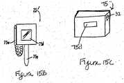
- Figure 15Aillustrates embodiments of a radiation dose evaluation system 15 according to embodiments of the present invention.
- the system 15includes a reader 75 and a set of radiation sensor patches 130'.
- the reader 75may include, for example, the reader 75' of Figure 15B or the reader 75" of Figure 15C .
- the sensor patches 30can be arranged as a strip of patches 30 held in a single-patient sized package 130p.
- the package 130pmay also include bar coded radiation calibration characterizing data labels 132 for the sensor patches 30 and/or a memory 167 in each or selected memory patches 30.
- the reader 75' as shown in Figure 15Bcan include the probe 75p, an optical wand 75w and a display screen 75d.
- the reader 75" as shown in Figure 15Ccan include a sensor port 32 and a display screen 75d.
- the reader 75can also include a RADFET bias circuit 75b.
- the reader 75is a portable flat pocket or palm size reader that a clinician can carry relatively non-obtrusively in his/her pocket or a similar sized casing.
- the reader 75may hold a power source 78 and plurality of operational software modules including: an optical bar code reader module 76, a zero-dose threshold voltage data module 77, a radiation dose conversion module (based on a predetermined voltage threshold to radiation dose response curve) 79, and a threshold voltage post radiation data module 80.
- the reader 75can be configured to supply a bias current to the RADFET by attaching to the sensor patch 30 and electrically contacting the conductive probe region 30p or the electrical contacts 31.
- the reader 75can measure the voltage shift response of the RADFET on the sensor patch 30 and calculate radiation dose based on the shift and the dose conversion algorithm.
- the reader 75can display the results to the clinician (such as on an integrated LCD screen 75d incorporated into the body of the reader) and may be configured to download or upload the data to another device (such as a computer or computer network) for electronic record generation or storage.
- the dose amountcan be calculated for each sensor patch 30 used.
- the systemcan be configured to generate an average or weighted average of the dose amount determined over a plurality of the patches.
- the systemcan be configured to discard that sensor value or to alert the clinician of potential data corruption.
- much smaller valuesare predicted in sensitive areas away from the targeted zone and the system can be configured to evaluate whether the sensor is in a primary location or in a secondary zone as regards the radiation path.
- the present inventionmay be embodied as a system, or computer program product. Accordingly, the present invention may take the form of an entirely hardware embodiment or an embodiment combining software and hardware aspects. Furthermore, the present invention may take the form of a computer program product on a computer-usable storage medium having computer-usable program code means embodied in the medium. Any suitable computer readable medium may be utilized including hard disks, CD-ROMs, optical storage devices, or magnetic storage devices.
- the computer-usable or computer-readable mediummay be, for example but not limited to, an electronic, magnetic, optical, electromagnetic, infrared, or semiconductor system, apparatus, device, or propagation medium. More specific examples (a non-exhaustive list) of the computer-readable medium would include the following: an electrical connection having one or more wires, a portable computer diskette, a random access memory (RAM), a read-only memory (ROM), an erasable programmable read-only memory (EPROM or Flash memory), an optical fiber, and a portable compact disc read-only memory (CD-ROM).
- RAMrandom access memory
- ROMread-only memory
- EPROM or Flash memoryerasable programmable read-only memory
- CD-ROMportable compact disc read-only memory
- the computer-usable or computer-readable mediumcould even be paper or another suitable medium upon which the program is printed, as the program can be electronically captured, via, for instance, optical scanning of the paper or other medium, then compiled, interpreted or otherwise processed in a suitable manner if necessary, and then stored in a computer memory.
- Computer program code for carrying out operations of the present inventionmay be written in an object oriented programming language such as LABVIEW, Java®, Smalltalk, Python, or C++. However, the computer program code for carrying out operations of the present invention may also be written in conventional procedural programming languages, such as the "C" programming language or even assembly language.
- the program codemay execute entirely on the user's computer, partly on the user's computer, as a stand-alone software package, partly on the user's computer and partly on a remote computer or entirely on the remote computer. In the latter scenario, the remote computer may be connected to the user's computer through a local area network (LAN) or a wide area network (WAN), or the connection may be made to an external computer (for example, through the Internet using an Internet Service Provider).
- LANlocal area network
- WANwide area network
- Internet Service Providerfor example, AT&T, MCI, Sprint, EarthLink, MSN, GTE, etc.
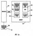
- FIG 16is a block diagram of exemplary embodiments of data processing systems that illustrate systems and computer program products in accordance with embodiments of the present invention.
- the processor 310communicates with the memory 314 via an address/data bus 348.
- the processor 310can be any commercially available or custom microprocessor.
- the memory 314is representative of the overall hierarchy of memory devices containing the software and data used to implement the functionality of the data processing system.
- the memory 314can include, but is not limited to, the following types of devices: cache, ROM, PROM, EPROM, EEPROM, flash memory, SRAM, and DRAM.
- the memory 314may include several categories of software and data used in the data processing system 305: the operating system 352; the application programs 354; the input/output (I/O) device drivers 358; a radiation estimator module 350; and the data 356.
- the data 356may include threshold voltage data 340 (zero dose and post irradiation dose levels) which may be obtained from a reader data acquisition system 320.
- the operating system 352may be any operating system suitable for use with a data processing system, such as OS/2, AIX, OS/390 or System390 from International Business Machines Corporation, Armonk, NY, Windows CE, Windows NT, Windows95, Windows98, Windows2000 or Windows XP from Microsoft Corporation, Redmond, WA, Unix or Linux or FreeBSD, Palm OS from Palm, Inc., Mac OS from Apple Computer, or proprietary operating systems.
- the I/O device drivers 358typically include software routines accessed through the operating system 352 by the application programs 354 to communicate with devices such as I/O data port(s), data storage 356 and certain memory 314 components and/or the image acquisition system 320.
- the application programs 354are illustrative of the programs that implement the various features of the data processing system 305 and preferably include at least one application that supports operations according to embodiments of the present invention.
- the data 356represents the static and dynamic data used by the application programs 354, the operating system 352, the I/O device drivers 358, and other software programs that may reside in the memory 314.
- the radiation estimation module 350may also be incorporated into the operating system 352, the I/O device drivers 358 or other such logical division of the data processing system.
- the present inventionshould not be construed as limited to the configuration of Figure 16 , which is intended to encompass any configuration capable of carrying out the operations described herein.
- the radiation estimation module 350includes computer program code for estimating radiation dose based on the measured threshold voltage shift.
- the I/O data portcan be used to transfer information between the data processing system and the reader data acquisition system 320 or another computer system or a network ( e.g ., the Internet) or to other devices controlled by the processor.
- These componentsmay be conventional components such as those used in many conventional data processing systems that may be configured in accordance with the present invention to operate as described herein.
- each block in the flow charts or block diagramsrepresents a module, segment, or portion of code, which comprises one or more executable instructions for implementing the specified logical function(s).
- the functions noted in the blocksmay occur out of the order noted in the figures. For example, two blocks shown in succession may in fact be executed substantially concurrently or the blocks may sometimes be executed in the reverse order, depending upon the functionality involved.
- FIG 17is a block diagram illustration of one embodiment of a reader 75 according to the present invention.
- the reader 75includes an operating system 422, a processor 410, a power source 456, and a user activation /input module 460.
- the reader 75can also include a RADFET interface module 475 and a sensor patch memory interface module 478.
- the sensor patch 30may be configured to communicate wirelessly with the reader 75.
- the interface module 475may be configured to receive wireless signals from the sensor patch 30.
- the reader 75may optionally include a sensor patch identifier module 428 to track which sensor patch 30 has a particular radiation dose result.
- the identifier module 428may allow the user to input via an input keypad associated with the reader, an alphanumeric identifier (F1, B1, etc.) for a particular sensor patch prior to obtaining the reading, or a bar code identifier or other automated identifier means can be used (such as scanning a bar code label on the sensor and the like).
- an alphanumeric identifierF1, B1, etc.
- a bar code identifier or other automated identifier meanscan be used (such as scanning a bar code label on the sensor and the like).
- the reader 75also includes pre-radiation (zero dose) threshold voltage data 440, post radiation threshold voltage data 441, and a radiation estimation module 458.
- the radiation estimation module 458may also be configured to extrapolate to arrive at the radiation dose delivered to the tumor site.
- the reader 75may also include an optical bar code scanner module 476 to allow the reader to input the characterizing zero dose threshold voltage values by optically reading same.
- calibration datacan be entered via the bar the bar code scanner 476 or memory 67 from the patches 30. Alternatively, the clinician can enter the desired data in situ as desired.
Landscapes
- Health & Medical Sciences (AREA)
- Life Sciences & Earth Sciences (AREA)
- Engineering & Computer Science (AREA)
- Biomedical Technology (AREA)
- General Health & Medical Sciences (AREA)
- Physics & Mathematics (AREA)
- Nuclear Medicine, Radiotherapy & Molecular Imaging (AREA)
- Animal Behavior & Ethology (AREA)
- Pathology (AREA)
- Public Health (AREA)
- Veterinary Medicine (AREA)
- Radiology & Medical Imaging (AREA)
- General Physics & Mathematics (AREA)
- High Energy & Nuclear Physics (AREA)
- Molecular Biology (AREA)
- Spectroscopy & Molecular Physics (AREA)
- Measurement Of Radiation (AREA)
- Radiation-Therapy Devices (AREA)
Description
- The present invention generally relates to the assessment or quantitative evaluation of the amount of radiation delivered to a patient undergoing radiation therapy.
- Conventionally, radiation therapy is delivered over a successive series of radiation treatment sessions. High-energy photons and/or electrons are carefully directed and/or focused from anex vivo radiation source so that they travel into a targeted treatment area in a patient's body. The size, shape, and position of the treatment area (typically where a tumor is or was) as well as its anatomical location in the body and its proximity to sensitive normal tissues are considered when generating a particular patient's treatment plan. That is, the treatment is planned so as to deliver a suitably high dose of radiation to the tumor or targeted tissue while minimizing the dose to nearby sensitive tissue that typically cannot be completely avoided. Directing radiation into non-affected regions may produce undesired side effects particularly as it relates to tissue that may be sensitive to certain dosages of radiation. Unfortunately, even when the patient plan is carefully constructed to account for the location of the cancerous tissue and the sensitive non-affected regions, even small errors in set-up due to beam angle or patient position during delivery of the radiation therapy can inadvertently misdirect radiation into those regions or can influence the dose amount that is actually received by the targeted tissue. Further, the demand for radiation treatment equipment is typically relatively high and this demand may limit the set-up time allowed or allocated in the treatment room between patients.
- In the past, implantable devices for oncology applications have been proposed to evaluate the radiation dose amount receivedin vivo at the tumor site.See e.g., United States Patent No.
6,402,689 to Scarantino et al. , the contents of which are hereby incorporated by reference herein. Measuring the radiation at the tumor sitein vivo can provide improved estimates of doses received. However, for certain tumor types or situations, a skin-mounted or external surface radiation dosimeter may be desirable and sufficient for clinical purposes. - Conventional external or skin-mounted radiation dosimeter systems use semiconductor circuitry and lead wires that power/operate the dosimeters. These types of dosimeters are available from Scandatronics and/or IBA ("Ion Beam Applications") having an international headquarters location in Belgium. While these radiation dosimeter systems may provide radiation dose estimations, they can, unfortunately, be relatively expensive. Further, these types of dosimeters are used for a plurality of patients potentially raising sterility or cleanliness problems between patients. Conventional dosimeter systems may also require substantial technician time before and during the radiation session. For example, conventional dosimeter systems need to be calibrated before the radiation session may begin. In addition, the lead wires can be cumbersome to connect to the patients and may require excessive set-up time as the technician has to connect the lead wires to run from the patient to the monitoring system and then store the lead wire bundle between patient treatment sessions. Therefore, technicians do not always take the time to use this type of system, and no confirmation estimate of the actual radiation delivered is obtained.
- Other radiation sensors include thermo-luminescent detectors (TLD's). However, while TLD detectors do not require wires during operation, they are analyzed using a spectrophotometer (that may be located in an offsite laboratory) and are not conducive to real-time readings.
- In view of the foregoing there remains a need for improved economical and easy to use radiation dosimeters.
US 5,444,254 discloses a dosimeter patch according to the preamble ofclaims - It is a further object of the present invention to provide devices that can reduce labor set-up time in the radiation treatment chamber over conventional evaluation methods and devices.
- It is an additional object of the present invention to provide a memory storage device on the patch to record the dose history of the patch. This memory storage device may be queried at any time in order to obtain a record of the dose applied to the patch. Other information, such as patient identification, time, date, hospital, therapist, state of the device, dosed/undosed and calibration data may be stored in the memory storage device.
- These and other objects can be satisfied by the present invention by a disposable, single-use skin mounted radiation dosimeter that has a self-contained package that is small, adhesively attachable to the skin of the patient, and operates in a relatively easy to operate and read manner without requiring the use of lead wires.
- According to a first aspect of the present invention there is provided an external use radiation dosimeter patch as described in
claim 1. - According to a second aspect of the present invention there is provided an external use radiation dosimeter patch as described in
claim 2. - Preferably, the sensor patch may be pre-dosed and/or calibrated before the sensor patch is secured to the patient. The obtained data may be stored in an electronic storage device provided on the sensor patch itself. The storage device may be, for example, an EEPROM. Other information, such as the patient's name, the doctor's name, the test date and the like, may also be stored in the storage device provided on the sensor patch. Alternatively, the data can be stored on a computer readable memory integrated on a physical record sheet that can be placed in the patient's file.
- According to an embodiment of the present invention there is provided a system for monitoring radiation administered to a patient during a therapeutic treatment, the system comprises:
- at least one dosimeter holding a circuit with at least one MOSFET and an external reader contact region thereon, the at least one MOSFET having an associated threshold voltage that changes when exposed to radiation; and
- an external portable dose-reader being configured to make electrical contact with the dosimeter by physically engaging with the contact region on the dosimeter to obtain voltage threshold data corresponding to the dose amount of radiation exposure exposed to the dosimeter in use; characterised in that each dosimeter is a single-use dosimeter patch, the patch comprising a resilient substrate (body) configured to, in position, be in intimate contact with skin of a patient, the substrate (body) comprising opposing upper and lower primary surfaces and each dosimeter has a perimeter that is devoid of outwardly extending loose lead wires.
- Advantageously, the at least one dosimeter patch is a plurality of discrete sensor patches and the reader is configured to serially contact with each respective sensor patch to obtain the threshold voltage value associate therewith.
- Conveniently, a sheet of sensor patches may be pre-dosed and/or calibrated simultaneously or individually before the sensor patches are secured to the patient. The calibration and/or pre-dosing may be performed at the original equipment manufacturer (OEM) or at the actual test site. The sheet of sensor patches may includes about 30 to about 100 sensors. The sensors may also be provided in a high density array of sensors where so many sensors are provided in a certain area of the high density array, for example, multiple sensors may be provided per square inch or per 3 by 3 inch regions of the high density array.
- According to an embodiment of the present invention, there is provided a kit of disposable single-use radiation dosimeter patches comprising:
- a plurality of discrete single-use dosimeter patches, each patch comprising a conformable resilient substrate holding a circuit with an FET that changes a parameter in a detectable predictable manner when exposed to radiation and wherein, the circuit further comprises electronic memory with stored calibration data, the body comprising opposing upper and lower primary surfaces, wherein the dosimeter patch in use, is devoid of externally hanging lead wires, and wherein the kit is configured to provide at least a first plurality of patches that are configured to be concurrently positioned at spaced apart locations on a common subject.
- Preferably the operational electronic component may be a radiation sensitive biased MOSFET or MOSFETs (such as MOSFET pairs) and the detectable operational parameter that changes can be the MOSFET threshold voltage(s).
- Furthermore, a medical grade adhesive is supplied on the lower primary surface of the sensor body such that the sensor may be adhered to the patient's skin. Alternatively, an adhesive coverlay may be provided over the body of the sensor to secure the sensor to the patient's skin.
- According to yet another embodiment of the present invention there is provided a computer program product for evaluating a radiation dose delivered to a patient during a therapy session, the computer program product comprising:
- a computer readable storage medium having computer readable program code embodied in the medium, the computer-readable program code comprising:
- computer readable program code for serially receiving calibration data associated with each of a plurality of single use sensor patches that is stored in memory on the respective sensor patches; and
- computer readable program code for determining a voltage threshold shift of each of the disposable sensor patches based on the received calibration data from each sensor patch after radiation to determine the radiation exposure of each of the plurality of sensor patches during a therapy session.
- Another embodiment is directed to a computer program product for evaluating a radiation dose delivered to a patient. The computer program product comprises a computer readable storage medium having computer readable program code embodied in the medium. The computer-readable program code comprises: (a) computer readable program code for receiving pre-irradiation threshold voltage data associated with a plurality of disposable sensor patches; (b) computer readable program code for accepting data from a reader configured to electrically serially contact each of the plurality of disposable sensors for a short time; and (c) computer readable program code for determining the voltage threshold shift of the disposable sensor patches after radiation to determine the radiation exposure.
- The foregoing and other objects and aspects of the present invention are explained in detail in the specification set forth below.
Figure 1 is a schematic illustration of a patient undergoing radiation treatment.Figure 2 is a block diagram of operations for monitoring patients undergoing radiation treatments.Figures 3A and3B are illustrations of sets of disposable dosimeter patches according to embodiments of the present invention.Figure 3C is an anatomical map of sensor location.Figure 4 illustrates an exemplary patient information form.Figures 5A and5B are schematic illustrations of sensor placement on a patient.Figure 6 is a schematic illustration of embodiments of a reader contacting the sensor to obtain the radiation dosage data according to embodiments of the present invention.Figure 7 is a schematic illustration of further embodiments of a reader receiving the sensor in a sensor port to obtain the radiation dosage data according to embodiments of the present invention.Figure 8A is a greatly enlarged side view of a disposable radiation dosimeter according to embodiments of the present invention.Figure 8B is a top view of the dosimeter shown inFigure 8A .Figure 8C is a partial cutaway view of a probe head for a reader according to embodiments of the present invention.Figure 9A is a schematic of embodiments of a sensor patch with a circuit thereon according to embodiments of the present invention.Figure 9B is a schematic of further embodiments of a sensor patch with a circuit thereon according to embodiments of the present invention.Figure 9C is a schematic of further embodiments of a sensor patch with a circuit thereon according to embodiments of the present invention.Figure 9D is a schematic of further embodiments of a sensor patch according to embodiments of the present invention.Figure 9E is a schematic of further embodiments of a sensor patch according to embodiments of the present invention.Figure 10A is a schematic illustration of a sheet of sensors according to embodiments of the present invention.Figure 10B is yet another schematic illustration of a sheet of sensors according to embodiments of the present invention.Figure 10C is a further schematic illustration of a sheet of sensors according to embodiments of the present invention.Figure 11 is a schematic of a circuit diagram of a MOSFET sensor with a reader interface and an optional memory.Figure 12A is a schematic of a threshold voltage reader circuit according to embodiments of the present invention.Figure 12B is a graph of the change in the threshold voltage value versus radiation dose.Figure 13 is a graph of the threshold voltage dependence on Ids using the voltage (V0) of the reader illustrated inFigure 12A .Figure 14A is a schematic of a circuit diagram with a MOSFET pair, the left side of the figure corresponding to an irradiation operative configuration and the right side of the figure corresponding to a read dose operative configuration.Figure 14B is a schematic of a circuit diagram with a MOSFET pair, the left side of the figure corresponding to an irradiation operative configuration and the right side of the figure corresponding to a read dose operative configuration.Figure 15A is a schematic of a system or computer program product for estimating radiation based on data taken from a point contact-reader data acquisition system according to embodiments of the present invention.Figure 15B is a block diagram illustrating a reader device according to embodiments of the present invention.Figure 15C is a block diagram illustrating a reader device according to further embodiments of the present invention.Figure 16 is a block diagram of a computer program having a radiation estimation module according to embodiments of the present invention.Figure 17 is a block diagram of a point-contact reader data acquisition system.Figure 1 illustrates an example of aradiation system 10 with aradiation beam source 20 directed at a patient50 having a tumor site. The patient50 can be positioned so as to be aligned and stationary with respect to thebeam 20b (illustrated by the diverging dotted lines) during the treatment. As such, the patient50 can be arranged in any desired position depending on the direction of the beam, the location of the tumor, and the type of radiation therapy system employed. As shown, the patient is reclined, substantially flat and face up on a table so that thebeam 20b is directed into the targeted tumor site in the body as the patient undergoes radiation therapy in a treatment session. Typically, the patient will undergo a plurality of successive treatment sessions over a treatment period. Each treatment session may be planned to administer radiation doses of between about 1-2 Gray (100-200cGy) with an overall treatment limit of about 35-80 Gray.- To help monitor or estimate the amount of radiation that is delivered to the patient during a treatment session, at least one disposable single-use
dosimeter sensor patch 30 can be positioned externally on the skin of thepatient 50. As used herein, "single-use" is used to refer to a use for a single patient during a treatment session. Thesensor patch 30 may be episodically worn or continuously worn. It will be understood that a treatment session may include an active radiotherapy administration during a single treatment session or serially spaced apart treatment sessions. The treatment session may have a duration of minutes, hours, days and the like. Furthermore, a calibration dose obtained before thesensor patch 30 is positioned on a patient is not to be considered the "single-use." - As shown in
Figure 1 , a plurality ofsensor patches 30 are located both on the front and back of thepatient 50. Thesensor patches 30 are configured to change an operational parameter in a predictable manner that correlates to radiation dose it receives, as will be discussed further below. Thesensor patch 30 can be configured so as to be self-contained and discrete and devoid of dangling lead wires extending to a remote power source or operating system during use and in position on the patient. As such, a reader, for example, reader75 (Figures 6 and7 ), can be configured to obtain the data from thesensor patch 30 by, for example, electrically contacting with eachsensor patch 30 of interest. - As used herein, the reference number"75" will be used to refer generally to a reader device according to embodiments of the present invention. Particular embodiments of a
reader device 75 may be referred to using thereference number 75 and one or more primes attached thereto. For example, particular embodiments of the reader device may be denoted75' or75". This convention may similarly be used with respect to other features of the present invention. For example, the reference number"30"' will be used to refer to particular embodiments of a sensor patch herein. It will be understood that features discussed with respect to any embodiment of the present invention may be incorporated into other embodiments of the present invention even if these features are not discussed specifically with reference to each individual embodiment. - Referring to
Figure 2 , operations that can be carried out to monitor the radiation dose that is delivered to a patient undergoing radiation therapy are illustrated. At least one single-use disposable dosimeter sensor patch can be releasably secured to the skin of the patient (block 100). The sensor patch may be calibrated and/or pre-dosed before being attached to the patient (block 101). The calibration and/or pre-dosing of the sensor patch may be done on an individual patch basis or many sensor patches may be calibrated and/or pre-dosed in batches simultaneously as discussed further below. The patch(es) can be conveniently attached to the patient in operation-ready condition before the patient enters the radiation treatment room or chamber (block 102) to limit or reduce the set-up time required or the "down-time" of the equipment or the treatment room. In other words, the sensor patch or patches may be secured to the patient prior to his/her entry into the radiation treatment room. A pre-irradiation or pre-dose measurement or reading of data associated with an operational parameter of the sensor patch(es)30 can be obtained prior to initiation of the radiation treatment (block 105). The data can be obtainedin situ, with the sensor patch(es)30 in position on the patient. Alternatively, the pre-dose data can be established prior to positioning the sensor patch(es) onto the subject as discussed above and the data then transferred to the reader or associated controller and/or computer at a desired time. The post-radiation reading can be taken when the patient leaves the treatment room to evaluate the dose delivered during the treatment session to limit the amount of room-use time. Thesensor patches 30 can be removed from the patient and then read by a handheld portable or a bench top reader. The reading can be obtained while thesensor patches 30 remain on the patient. The reading may be able to be obtainedin situ during the treatment session (without removing the sensor patch(es) from the patient) to provide real-time feedback to the clinician estimating whether the desired dose is being administered to the patient. The temperature of the sensor patch (such as at a location adjacent the circuitry) or of the subject (skin or core body) can also be ascertained or obtained and taken into account when calculating the radiation dose. In any event the dose reading can be obtained without requiring external powering or externally applied biasing of thesensor patches 30 during the radiation treatment. A plurality ofdiscrete sensor patches 30 can be positioned to cover a region on the skin that is in the radiation beam path so as to reside over the tumor site. One ormore sensor patches 30 can also be positioned in radiation sensitive areas of the body to confirm stray radiation is not unduly transmitted thereto.Figure 2 illustrates that a sensor patch can be located at the neck over the thyroid when the tumor site is over the chest region. As such, sensitive regions include, but are not limited to, the thyroid, the spine, the heart, the lungs, the brain, and the like. In any event, referring again toFigure 1 , radiation is administered to the patient in a first treatment session (block 110). Data associated with a change in an operational parameter in the dosimeter sensor patch circuitry may be obtained from the sensor patch using a reader device (block 120) after administering the radiation to the patient (block 110). A sensor patch may be removed from the patient and inserted into the reader device to transfer the data from the sensor patch. The reader device may contact the sensor patch as discussed further below. The radiation dose received by the patient can be determined based on the obtained data (block 125). The obtained data as well as other information may be stored in a memory device included on the sensor patch as described further below (block 130). - The sensor patch does not require lead wires extending from a remote power source or computer system to operate. Instead, the
sensor patch 30 is configured to be a discrete patch (or a patch array of sensors) that can transmit or relay data upon contact with and/or insertion into areader device 75 and may store data in an electronic memory device included on the sensor patch. In certain embodiments, thesensor patch 30 may be configured to communicate wirelessly with thereader 75. The radiation dose received by thesensor patch 30 can be determined and used to estimate the dose received by the patient during the radiation therapy session based on the data obtained by the reader. The reader itself can be a handheld portable unit that may or may not include wires to connect with a remote controller or computer as will be discussed further below. In any event, the operations can be carried out for each or a selected radiation treatment session. If the operations are repeated for each treatment session, a cumulative amount of delivered radiation can be estimated/confirmed to allow a clinician to evaluate whether additional treatments are desired. Figure 3A illustrates that thesensor patches 30 can be provided in a kit or set130 including a plurality ofsensors 30p. The plurality ofsensors 30p may be configured in sufficient numbers or types for a single patient or so as to be able to supply sensors across a plurality of patients. In certain embodiments, a strip of sixsensor patches 30 can be packaged together as a set130' as shown inFigure 15A . It is contemplated that, depending on the treatment type, the treatment location, the tumor site, and the like, different numbers ofsensor patches 30 may be used for different patients. Thus, if thesensor kit 130 is sized for a single patient, the kit may include from about 2 to about 10 ormore sensor patches 30 that can be selectively chosen for use by the clinician. Eachsensor patch 30 can be sterilized and sealed in a sterile package or thekit 130 itself can be sized and configured to hold a plurality of thesensor patches 30p in a sterile package that, once opened, can be either used or discarded. Similarly, if thesensor kit 130 is sized for multi-patient use, then larger quantities may be packaged individually, or in sets within the multi-patient package, together. The sterilization can be performed by heat or chemical exposure, such as by ethylene oxide sterilization. In certain embodiments, sterilization and/or sterile packaging may not be required.- As is also shown in
Figure 3A , eachsensor patch 30 can be packaged withpre-irradiation characterizing data 132. Thisdata 132 can be included in optically or electronically readable formats such as in bar code format for the reader to be able to read without having the clinician enter the information into a controller/computer. In certain embodiments, thedata 132 may be included in amemory storage device 67, for example, an electrically programmable memory such as an electrically erasable read only programmable memory (EEPROM), provided on eachsensor patch 30p as discussed further below. Thememory storage device 67 may include information such as patient identification, time, date, hospital, therapist, state of the device, dosed/undosed sensor data and calibration data. Thememory storage device 67 may further be used to store bias parameters and/or information with respect to measurement methodology for eachindividual patch 30. - Each
sensor patch 30 can have an individual calibration coefficient, dose data or characterizing data label located on thesensor patch 30 or as a corresponding label held with the package orkit 130. In other embodiments, eachsensor patch 30 produced in a common production run (off of the same wafer or chip) with substantially similar characterizing data may be packaged together and a single calibration characterizing data orlabel 132 can be included with theset 130 or sets or production run. In certain embodiments, the calibration related characterizing data can include the pre-irradiation threshold voltage value of a metal-oxide semiconductor field-effect transistor(s) (MOSFET(s)) that is measured at an OEM and provided in or with the sensor patch set130. - In certain embodiments, identifying indicia may be disposed on the
sensor patches 30 to allow a clinician to easily visually identify and/or account for the sensors used. For example,Figure 3A illustrates three discrete sensor patches labeled as1F, 2F, and3F as well as a sensor with a pictorial representation of aheart 4F (other visual images can also be used such as a yellow caution sign, other anatomical symbols, and the like). The heart or caution sensor patch30s can be positioned in a radiation sensitive area to detect the amount of radiation delivered to that area. Typically, the radiation beam is adjusted to reduce the radiation exposure to sensitive areas and a caution-sensitive sensor patch30s (or patches) can indicate whether adjustments need to be made to reduce the detected exposure for each or selected treatment sessions. The sensor patches30s used for sensitive detection may be configured with increased sensitivity for enhanced dose resolution capability for measuring small, residual, or stray doses of radiation (such as those located over critical organs which are not in the treatment volume). For example, for "normal" single use sensors may be configured to operate over a range of between about 50-500 cGy; the "high sensitivity" sensor might be configured to operate from about 1-50 cGy. In particular embodiments, thecircuit 30c (Figure 9A ) for the high sensitivity sensor30s includes at least one radiation-sensitive field-effect transistor (RADFET) that can be configured to produce a larger threshold voltage shift for a given amount of received or absorbed dose relative to thesensors 30 positioned in the window of the targeted treatment volume. The larger voltage shift may increase dose resolution and possibly dose repeatability. - In addition, single-use dosimeters can be optimized to work over a much lower dose range than multiple use dosimeters. Since the typical per day fraction for radiation therapy is about 200 cGy, the
dosimeter sensor 30 can be optimized for accuracy and repeatability over this dose range. A 50-500 cGy operating range should meet performance goals while providing adequate flexibility for varying treatment plans. A multiple-sessionfraction dosimeter sensor 30 may require a much larger dose range that depends on the number of fractions over which the sensor will operate. As used herein, "disposable" means that the sensor patch is not reusable and can be disposed of or placed in the patient's records. - As shown in
Figure 3A , the indicia can include an alphanumeric identifier such as the letter "F" located to be externally visible on thesensor patches 30. The letter "F" can represent that the sensors are placed on a first side or front of the patient.Figure 3B illustrates that a second set of sensors130' can be supplied, thesesensor patches 30 can be labeled with different indicia, such as1B, 2B, 3B and the like, representing that they are located at a different location relative to the first set (such as a second side or back of the patient). Using data from opposing outer surfaces can allow an interpolated radiation dose amount to be established for the internal tumor site. - It will be understood that the indicia described above, namely "F" and "B", are provided herein for exemplary purposes only and that indicia according to embodiments of the present invention are not limited by the examples provided. Any label, mark, color or the like may be used that would serve to distinguish one patch or set of patches from another patch or set of patches without departing from the teachings of the present invention. For example, instead of "F" and "B", the first set of
patches 130 may be blue and the second set of patches130' may be red. Furthermore, the indicia may be, for example, on the sensor patch itself or on an adhesive covering placed on or over the sensor patch without departing from the teachings of the present invention. Figure 3C illustrates a patientanatomical map 150 that can be used to identify where each of thesensor patches 30 are placed on the body of the patient. Themap 150 may be stored in the patient chart or file. For each treatment session for which dose monitoring is desired, the clinician can allocate the same sensor patch identifier ("A", "1F", etc...) to the same location. Themap 150 and/or indicia on thesensor patches 30 can, in turn, help the clinician consistently identify whether a particular location may have undue or deficient exposure. For example, if sensor patchF1 indicates a low radiation exposure, whileF3 indicates a relatively high exposure, and the two are positioned in the targeted beam region, either one or both of thesensor patches 30 is not functioning properly, or the radiation beam may need adjustment. Using substantially the same sensor patch position for successive treatment sessions may allow cumulative radiation dose data to be obtained and correlated to provide a more reliable indication of dose. The clinician may also draw markings on the patient's skin to help align thesensor patches 30 in relation thereto over the different treatments sessions.- In certain embodiments, the
discrete sensor patches 30 can be arranged to reside on a common substrate or to be attached to each other so as to define known or constant distances therebetween (not shown). Thesensor patches 30 may be configured to be at the body temperature of the patient during use or at room temperature, or temperatures in between. To establish a calculated dose amount, a temperature reading may be obtained, assumed, or estimated. In certain particular embodiments, the temperature may impact the operational change if substantially different from that upon which the calibration data is established. A first set-up pre-dose verification protocol can be carried out to deliver a first radiation dose and a first radiation dose value can be obtained for at least one selected patch to confirm that the radiation beam focus location is correct or suitable (or whether a sensitive area is receiving radiation). In addition, the system can be configured to map a dose gradient by correlating the determined radiation dose values at each patch location to the anatomical location on the subject of each patch. Figure 4 illustrates an exemplary patient dosimetry form99, which may be, for example, a paper sheet or computer printable document. The form99 can contain ananatomical map 150 as discussed above with respect toFigure 3C . Sicel Technologies, Inc. asserts copyright protection for the form illustrated inFigure 4 and has no objection to reproduction of the patent document, as it appears in the Patent and Trademark Office patent file or records, but reserves all other rights whatsoever.- As discussed above, the
map 150 may be used to identify and/or memorialize for the patient record where each of thesensor patches 30 are placed on the body of the patient during use. Ananatomical map 150 can be used to record the specifics of each radiation session and may be placed in each patient's chart or file to assist the doctor and/or clinician. Patients being treated on an ongoing basis may have multiple dosimetry forms99 in their chart and/or file corresponding to each treatment session. As noted above, for each treatment session, the clinician can, as desired, allocate the same sensor patch identifier to the same location aided by themap 150. As further illustrated inFigure 4 , the dosimetry form99 may further include a dosimetry plan portion152, ameasurement data portion 154 and a sensor patch record portion156. - The dosimetry plan portion152 may include the patient's name, the date or dates the patient is scheduled for the treatment, the patient's doctor, and any information that may be specific to the patient or the patient's treatment. The
measurement data portion 154 may include information such as the date of the treatment and the therapist administering the treatment on that date. The sensor patch record portion156 may include labeled sections158 (A, B,..) giving each patient a discrete identifier which may correspond to sensor patch locations (A, B,...) with the identifiers indicated on theanatomical map 150. The sensor patch record portion156 may further include dosing data, for example, target and measured doses as illustrated inFigure 4 . The sensor patch record portion156 may further include the actual sensor patch used on the patient in each of the labeled sections158. As shown, the form99 can include two separate storage regions, namely a pre and post dose use storage region. In addition, the form99 can also allow a clinician to indicate whether the sensor patch was held in the entrance and/or exit field. - In certain embodiments, the
sensor patch 30 may contain a storage or memory device67 (Figures 3A ,9B ), the storage or memory device on the sensor patches may be accessed to determine dosing information etc. if this information fails to be recorded, is misplaced or requires verification. Furthermore, thememory device 67 included on thesensor patch 30 may further include the data recorded in themap portion 150, the dosimetry plan portion152 and themeasurement data portion 154 of the dosimetry form99. Accordingly, thememory device 67 on thesensor patch 30 may serve as an electronic dosimetry patient record form. It will be understood that the dosimetry form99 ofFigure 4 is provided for exemplary purposes only and that it is possible to provide data and/or hold sensor patches in alternate manners. Figure 5A illustrates the use of fiveprimary sensor patches 30 positioned over the targeted treatment region (on the front side of the patient) and one sensor patch30s positioned over the heart.Figure 5B illustrates threeprimary sensors 30 located over the back surface proximate the area corresponding to theunderlying tumor site 25.Figure 6 illustrates a reader or data acquisition device75' in point contact with theunderlying sensor patch 30 in order to detect the amount of radiation that thesensor patch 30 was exposed to during (or after) the treatment session. As discussed above, the sensor patch(es)30 can be secured to a patient's chart ordosimetry form 150 and read after removal from the patient. The reader75' illustrated inFigure 6 may be configured to contact a portion of an electrical circuit on thesensor patch 30 that includes a device that has an operating characteristic or parameter that changes upon exposure to radiation in a predictable manner to allow radiation doses to be determined. The reader75' can be configured with aprobe 75p that is configured to electrically contact an electrically conductive probe region on thesensor patch 30 so as to obtain a reading in a "short" time of under about 30 seconds, and typically in less than about 5-10 seconds, for each of thesensor patches 30.- Referring now to
Figure 7 a sensor patch30' disposed in a reader ordata acquisition device 75" according to further embodiments of the present invention. Sensor patches30' according to embodiments of the present invention may be adapted to be inserted into thereader 75". Similarly, thereader 75" is adapted to receive the sensor patch30'. As shown, the sensor patch30' is formed to include atab portion 36 that at least a portion of is sufficiently rigid to sustain its shape for proper electrical coupling when inserted into aport 32 in thereader device 75". As illustrated inFigure 7 , thereader 75" may include asensor port 32 and the sensor patch30' may be inserted into theport 32 in thereader 75" in order to detect the amount of radiation that the sensor patch30' was exposed to. Theport 32 can read thesensor patch 30 as it is held in selected orientations in theport 32. Theport 32 may be configured similar to conventional devices that read, for example, glucose strip sensors and the like. Theport 32 illustrated inFigure 7 may contain one or more electrical contacts configured to contact one or more electrical contacts on the sensor patch30' to electrically connect thereader 75" to an electrical circuit on the sensor patch30'. The electrical circuit on the sensor patch30' includes a radiation-sensitive component that has an operating characteristic or parameter that changes upon exposure to radiation in a predictable manner to allow radiation doses to be determined. As before, thereader 75" may obtain a reading in under about 30 seconds, and typically in less than about 5-10 seconds, for each of thesensor patches 30. - The
reader device 75" can be held in aportable housing 37. It may be pocket sized and battery powered. In certain embodiments, thereader device 75 may be rechargeable. As shown inFigures 7 ,15A and15B , thereader 75 may include adisplay portion 75d, for example, a liquid crystal display (LCD), to provide an interface to depict data to the doctor and/or technician. - The function of the
reader device 75 may be incorporated into any portable device adapted to receive asensor patch 30 in, for example, asensor port 32. For example, thereader 75 functionality/circuitry could be disposed in a personal digital assistant (PDA) that is adapted to include aradiation sensor port 32. Thereader 75 may further include aremote computer port 33. Theport 33 may be, for example, RS 232, infrared data association (IrDA) or universal serial bus (USB), and may be used to download radiation and/or other selected data from thesensor patch 30 to a computer application or remote computer. In some embodiments, thesensor patch 30 and thereader device 75 may both be equipped with an RF interface and information may be shared between them wirelessly. - In certain embodiments, as noted above, the
sensor patch 30 includes a storage ormemory device 67. In these embodiments, thereader 75 may be configured to obtain data stored in thememory device 67 of thesensor patch 30 using, for example, electrical contacts on thereader 75 and thepatch 30, to transfer the data stored in thememory device 67 of thesensor patch 30. This data obtained from the sensorpatch memory device 67 may, for example, be stored locally on thereader 75 or be downloaded to an application on, for example, a remote computer using aport 33 provided in thereader 75. Thememory device 67 on thesensor patch 30 may serve as a permanent record of the radiation dose and may contain a real time clock such that the obtained data may include a time and date stamp. Figure 8A illustrates exemplary embodiments of asensor patch 30. As shown, thesensor patch 30 includes asubstrate layer 60, acircuit layer 61, and anupper layer 62 that may be defined by a coating, film, or coverlay material. Thesubstrate layer 60 can be selected such that it is resilient, compliant, or substantially conformable to the skin of the patient. Examples of suitable substrate layer materials include, but are not limited to, Kapton, neoprene, polymers, co-polymers, blends and derivatives thereof, and the like. The underside or bottom of thesensor patch 30b may include a releasable adhesive30a so as to be able to attach to the skin of the patient. The adhesive30a can be a medical grade releasable adhesive to allow thesensor patch 30 to be secured to the skin during the treatment session and then easily removed without harming the skin. The adhesive30a can be applied to portions, or all, of the bottom surface of thesubstrate layer 60. Alternatively, the underside of thesensor patch 30b may be free of the adhesive. In this case, an adhesive coverlay30cl (Figure 9C ) may be placed over the body of thesensor patch 30 to secure thesensor patch 30 to the patient. The adhesive coverlay30cl may be sized to extend beyond the outer perimeter of thesensor substrate 60. The adhesive may be on a portion or all of the underside of the coverlay30cl.- In other embodiments, the sensor patch(es)30 is configured as a discrete, low profile, compact non-invasive and minimally obtrusive device that conforms to the skin of the patient. The sensor patch(es) may be less from about 0.25 to about 1.5 inches long and wide and have a thin thickness of from about 1 to about 5 mm or less. As such, the
sensor patches 30 can be secured to the patient and allowed to reside thereon for a plurality or all of the successive treatments. For example, thesensor patches 30 can be configured to reside on the patient in its desired position for a 1-4 week, and typically about a 1-2 week period. In this manner, thesame sensor patches 30 can be used to track cumulative doses (as well as the dose at each treatment session). An adhesive may be applied in a quantity and type so as to be sufficiently strong to withstand normal life functions (showers, etc.) during this time. Of course, selected ones of thesensor patches 30 can also be replaced as desired over the course of treatment as needed or desired. It may be important to attach thesensor patch 30 to the patient so that it makes and retains snug contact with the patient's skin. Air gaps between thesensor 30 and the patient's skin may cause complications with respect to obtaining the estimated dosage data. As illustrated inFigures 9D and9E , some embodiments of the present invention include the placement of an overlay material30fl over thesensor patch 30 to, for example, simulate placement of thesensor patch 30 beneath the patient's skin. This type of simulation may help to focus a narrow portion of the radiation beam in proximity to thesensor patch 30 and, therefore, increase the reliability of radiation measurement. Radiation measurement using the sensor subsurface electronics may be optimal at from about .5 to about 3 cm beneath the patient's skin, but typically is from about 1 to about 1.5 cm beneath the patient's skin. Accordingly, the overlay material30fl may be from about .5 to about 3 cm thick to simulate subsurface depth measurement conditions. The presence of this overlay material30fl may decrease the influence of air gaps between thesensor 30 and the patient's skin. - The overlay material30fl may be, for example, a resilient flubber like or flexible material that will conform to the skin such as an elastomeric or the like. As illustrated in
Figure 9D , the overlay material30fl may be placed between the adhesive coverlay30cl and thesensor patch 30 such that the adhesive coverlay30cl adheres thesensor patch 30 and the overlay material30fl to the patient's skin. As illustrated inFigure 9E , the overlay material30fl may be placed over the adhesive coverlay30cl and thesensor patch 30. In certain embodiments, the overlay material may have adhesive properties such that the overlay30fl may be adhered to the patient's skin. The overlay material30fl may also be integrated with thesensor patch 30 without departing from the teachings of the present invention. - Still referring to
Figure 8A , thesensor circuit layer 61 can be attached to, and/or formed on, theunderlying substrate layer 60. Theupper layer 62 can be configured as a moisture inhibitor or barrier layer that can be applied over all, or selected portions of, theunderlying circuit layer 61. It is noted that, as shown, the thickness of the layers60-62 are exaggerated for clarity and shown as the same relative thickness, however the thickness of the layers may vary. In certain embodiments, thesensor patch 30 is configured as a low profile, thin device that, when viewed from the side, is substantially planar. Figure 8B is a top view of embodiments of asensor patch 30. As shown, in certain embodiments, the circuit may layer include two conductiveprobe contacting regions 30p. During data readings/acquisitions, theprobe contacting regions 30p are configured to provide the connections between the operating circuitry on thecircuit layer 61 and the external reader. The probe contacting region(s)30p can be directly accessible or covered with a protectiveupper layer 62. If directly accessible, during operation, thereader 75 can merely press against, contact or clip to thesensor patch 30 to contact the exposed surface of theconductive probe region 30p to obtain the reading. If covered by anupper layer 62 that is a protective coating or other non-conductive insulator material, the clinician may need to form an opening into the coating or upper layer over theregion 30p so as to be able to penetrate into the sensor patch30' a certain depth to make electrical contact between theprobe region 30p and the probe of thereader 75p.Figure 8C illustrates aprobe portion 75p of the reader75' ofFigure 6 . As illustrated, theprobe portion 75p may be configured so that theprobe 75p includes, for example, conductive calipers, pinchers, or other piercing means, that can penetrate to make electrical contact with theprobe contacting region 30p of the sensor patch.Figure 9A illustrates a top view of embodiments of acircuit layer 61. As shown, thecircuit layer 61 includes the radiation sensitive operativesensor patch circuitry 30c that is self-contained and devoid of outwardly extending or hanging lead wires that connects to an operational member. Thesensor patch circuitry 30c includes a radiationsensitive device 63 that exhibits a detectable operational change when exposed to radiation. In certain embodiments, the radiationsensitive device 63 is a miniaturized semiconductor component such as a MOSFET. Suitable MOSFETs include RADFETs available from NMRC of Cork, Ireland. In certain embodiments, the MOSFET may be sized and configured to be about 1-2mm in width and length. Thecircuitry 30c also includes at least one conductive lead or trace64 extending from the radiationsensitive device 63 to the conductiveprobe contacting region 30p. In the embodiment shown, the conductiveprobe contacting region 30p is an annular ring. As also shown there are twotraces 64i, 64o that connect thedevice 63 to thering 30p. The traces or leads64' may be formed, placed, or deposited onto thesubstrate layer 60 in any suitable manner including, but not limited to, applying conductive ink or paint or metal spray deposition on the surface thereof in a suitable metallic pattern, or using wires. As desired, anupper layer 62 such as described above (such as epoxy) may be formed over the circuit layer61 (or even the entire sensor patch). Thesensor patch 30 may include integrated Electro Static Discharge (ESD) protection, thereader 75 may include ESD protection components, or the user/operator may use ESD straps and the like during readings.- In particular embodiments, the
sensor patch 30 andcircuit 30c can be configured with two or more MOSFETS. In embodiments configured to have two MOSFETS, one may be positioned over the other on opposing sides of the substrate in face-to-face alignment to inhibit orientation influence of the substrate. (not shown). Additionally, other materials,e.g., certain epoxies, can be used to both encapsulate the MOSFETs and provide further scattering influence to facilitate isotropic response of the MOSFETs. In addition, there are well known influences of radiation backscatter from the surface of patients on whom surface-mounted dosimeters are used. The backscatter effect can be taken into account when calculating an entrance or exit dose or sufficient build-up may be provided on the top of the dosimeter to promote the equilibration of scattered electrons.See,Cancer, Principles and Practice of Oncology, 3d edition, ed. VT DeVita, S. Hellman, and SA Rosenberg (JB Lippincott Co., Phila., 1989), the contents of which are hereby incorporated by reference as if recited in full herein. Figure 9B is a top view of further embodiments of a sensor patch30' that includes atab portion 36 that is adapted to be received by a reader, for example,reader 75" illustrated inFigure 7 . As shown, thecircuit 30c' includes acircuit layer 61 that includes at least oneelectrical contact 31 shown as a plurality of substantially parallel leads. During data readings/acquisitions, the sensor patch30' is inserted into thereader port 32 of thereader 75" (Figure 7 ) and the at least oneelectrical contact 31 is configured to provide the electrical connections between the operating circuitry on thecircuit layer 61 and theexternal reader 75". The electrical contact(s)31 may be covered with a protective upper layer62 (Figure 8A ). If covered by anupper layer 62 that is a protective coating or other non-conductive insulator material, the clinician may need to form an opening into the coating or upper layer over the electrical contact(s)31 so these contact(s)31 may make electrical contact with the reader via sensor port32 (Figure 7 ).Figure 9B further illustrates thecircuit layer 61 that includes the radiation sensitive operativesensor patch circuitry 30c'. Thesensor patch circuitry 30c' includes a radiationsensitive device 63 that exhibits a detectable operational change when exposed to radiation and may include amemory device 67. In certain embodiments, the radiationsensitive device 63 is a miniaturized semiconductor component such as a MOSFET. Suitable MOSFETs include RADFETs available from NMRC of Cork, Ireland. In certain embodiments, the MOSFET may be sized and configured to be about 1-2mm in width and length. Thecircuitry 30c' also includes at least one conductive lead or trace64' extending from the radiationsensitive device 63 and/or thememory device 67 to the at least one electrical contact(s)31. The traces or leads64' may be formed, placed, or deposited onto thesubstrate layer 60 in any suitable manner including, but not limited to, applying conductive ink or paint or metal spray deposition on the surface thereof in a suitable metallic pattern, or using wires. As desired, anupper layer 62 such as described above (such as epoxy) may be formed over the circuit layer61 (or even the entire sensor patch). Eachsensor patch 30 may be from about 0.25 to about 1.5 inches long and wide and have a thin thickness of from about 1 to about 5 mm or less.- As discussed above with respect to
Figure 8A , the underside or bottom of thesensor patch 30b includes a releasable adhesive30a so as to be able to attach to the skin of the patient. The adhesive30a can be a medical grade releasable adhesive to allow thesensor patch 30 to be secured to the skin during the treatment session and then easily removed without harming the skin. The adhesive30a can be applied to portions, or all, of the bottom surface of thesubstrate layer 60. Referring now toFigure 9C , the underside of thesensor patch 30b may be free of the adhesive. As illustrated, an adhesive coverlay30cl may be placed over the entire body of thesensor patch 30 to secure thesensor patch 30 to the patient. As further illustrated, the adhesive coverlay30cl may be sized to extend beyond the outer perimeter of thesensor substrate 60 and leave thetab portion 36 of the sensor30' exposed. The adhesive provided on the underside of the coverlay30cl may be provided on a portion of the coverlay30cl, for example, the portion of the coverlay30cl contacting the patient's skin outside the perimeter of thesensor substrate 60, or on the entire underside of the coverlay30cl. Sensor patches 30 according to embodiments of the present invention may be provided individually or in sheets containingmultiple sensor patches 30. In particular, thesensor patches 30 may be fabricated in high-density sheets. As used herein, "high density" refers to multiple sensor patches provided on a unitary sheet. High density is intended to encompass very large sheets containing, for example, hundreds or thousands of sensors, as well as, for example, 3X 3 regions of these very large sheets typically including 6 or more sensors per region. Providing thesensor patches 30 includingmemory devices 67, for example EEPROMs, onhigh density sheets 200 as illustrated inFigures 10A and10B provide the capability of calibrating and/or pre-dosing the entire sheet ofsensor patches 30 at one time. As shown inFigure 10A , thesheets 200 may include perforations for subsequent separation of theindividual sensor patches 30 from thehigh density sheet 200. In certain embodiments, the sheet ofsensor patches 200 may include from about 30 to about 100sensor patches 30 per sheet. In other embodiments,multiple patches 30 may be provided per square inch of thehigh density sheet 200 and/ormultiple patches 30, typically at least 6 patches, may be provided in a 3 by 3 inch region of the high density sheet.- The
sensor patches 30 may be calibrated at the factory or OEM. Each of thesensor patches 30 or theentire sheet 200 ofsensor patches 30 may be calibrated by providing a wire(s)205 illustrated inFigure 10B that electrically couples each of thesensor patches 30 on thesheet 200. For ease of reference, only a single electrical line to one sensor is shown onFigure 10B . The calibration data may be provided to thesensor patches 30 through the wire(s)205 and may be stored in thememory storage device 67 of thesensor patch 30. The ability to calibrate a plurality ofsensor patches 30 simultaneously may provide more precision in the dosimetry process and, therefore, possibly more reliable results. It will be understood that thesensor patches 30 may each have a dedicated wire or the sheet can have a calibration line all connected to a common lead206 as shown inFigure 10e that may be used to calibrate and/or pre-dose thesensor patches 30 individually. - As discussed above, the
sensor patches 30 may be pre-dosed,i.e. dosed prior to placement on the patient. Dosing a sensor patch may include, for example, setting the amount of radiation to be delivered to a patient and the particular region(s) on the patient to which the radiation should be delivered. This process is typically performed by a physicist and can be very time consuming. The possibility of accurately pre-dosing asensor patch 30 may significantly reduce the need for a physicist to be involved in the dosimetry confirmation process. In other words, using reliable dose patches can reduce the time a physicist expends to confirm the treatment beam and path dose. - It will be understood that
sensor patches 30 adapted to be received by areader 75 are not limited to the configuration illustrated in the figures provided herein. These figures are provided for exemplary purposes only and are not meant to limit the present invention. For example, the sensor patch30' ofFigure 9B can be configured with a geometry that allows it (entirely or partially) to be received by areader 75". The insertable geometry may take the form of an elongated tab, one end of the tab containing the radiation sensitive circuitry as well as the memory and the other end of the tab containing the electrical contacts for insertion into the reader device (not shown). - As shown in
Figure 11 , in certain embodiments, the radiationsensitive device 63 is a RADFET. The RADFET can be biased with a gate/drain short so that it acts as a two-terminal device.Figure 11 illustrates a portion of thecircuit 30c with aRADFET 63 and two associatedreader 75 interface or contact points63I1, 63I2.Figure 12A illustrates a reader75 (upper broken line box) and thecircuit 30c (lower broken line box) with theRADFET 63 configured with a gate to drain short. As shown, thereader 75 can include aRADFET bias circuit 75b that includes a controlled current source to allow a voltage reading to be obtained corresponding to the threshold voltage of the RADFET. - As shown by the graph in
Figure 12B , changes in surface state charge density induced by ionizing radiation causes a shift in threshold voltage in the RADFET.Figure 12B illustrates a radiation response of a standard P210W2 400nm implanted gate oxide RADFET with lines for 0V (the -0- marked line) and 5V (the line with the -*- markings) irradiation bias responses. To obtain the amount of threshold voltage ("Vth") shift, the Vth value (zero dose) can be subtracted from the post-irradiation value and the calibration curve used to determine radiation dose. The calibration curve can be pre-loaded into the controller of the reader or a computer to provide the dose data. In certain embodiments, when obtaining the readings, the clinician may wear grounding straps to reduce static sensitivity of the circuitry. In certain embodiments, such as where contact points are exposed, ESD protection may be integrated into thesensor patch 30 itself. - As shown in
Figure 12A , the Vth change can be measured by determining the change in applied gate voltage necessary to induce a set current flow. As noted above, the RADFET characterization data can be obtained prior to exposure to radiation (zero dose). Thus, the starting threshold voltage of thesensor patch 30 will be known froma priori information (or can be obtained by the clinician prior to placing on the patient or after on the patient but before radiation exposure) and can be placed in thereader 75 or computer associated or in communication therewith. Figure 13 illustrates the threshold voltage relationship between output voltage (voltage) and current Ids (the electrical current, drain-to source, in microamps) as measured using the output voltage of the reader circuit shown inFigure 12A . In operation, the reader circuit is configured to contact the sensor to provide a constant current source to the circuit so as to be able measure Vth at a substantially constant or fixed bias condition.Figures 14A and14B illustrate alternate examples of MOSFET basedcircuits 30c. Eachcircuit 30c employs aRADFET pair 63p (Figure 14A ),63p' (Figure 14B ) as the radiationsensitive device 63. The configuration on the left of each of these figures illustrates the irradiation configuration and the configuration on the right illustrates the read dose configuration. In the example shown inFigure 14A , theRADFET pair 63p are differentially biased during irradiation to create different voltage offsets. Each of the RADFETs in thepair - In the example shown in
Figure 14B , one of theRADFETs 63p1' in thepair 63p is selectively implanted with dopant ions to shift the threshold voltage (Vth) of that RADFET with respect to theother RADFET 63p2'. The ion implantation can be carried out in various manners as known to those of skill in the art, such as by masking one of the FETs with photoresist to inhibit ions from entering into the gate region. As is well known, using the proper implant species and/or dopant material can increase the FET sensitivity to radiation effects. In certain embodiments of the present invention, a MOSFET (RADFET) pair is used to effectively provide "differential biasing" without the need to apply an external voltage and without the need for a floating gate structure. That is, the MOSFETs can be configured to be individually unbiased and readings of the two MOSFETs (one at a different threshold voltage value) generates the differential biasing. In particular embodiments, this radiation sensitive MOSFET pair configuration that does not require floating gate structures and/or external voltage can be used in implantable as well as skin mounted sensors, such as in implantable sensors used as described in United States Patent No.6,402,689 to Scarantino et al. Figure 15A illustrates embodiments of a radiationdose evaluation system 15 according to embodiments of the present invention. As shown, thesystem 15 includes areader 75 and a set of radiation sensor patches130'. Thereader 75 may include, for example, the reader75' ofFigure 15B or thereader 75" ofFigure 15C . Thesensor patches 30 can be arranged as a strip ofpatches 30 held in a single-patientsized package 130p. As before, thepackage 130p may also include bar coded radiation calibration characterizingdata labels 132 for thesensor patches 30 and/or amemory 167 in each or selectedmemory patches 30. The reader75' as shown inFigure 15B can include theprobe 75p, anoptical wand 75w and adisplay screen 75d. Thereader 75" as shown inFigure 15C can include asensor port 32 and adisplay screen 75d. Thereader 75 can also include aRADFET bias circuit 75b. In certain embodiments, thereader 75 is a portable flat pocket or palm size reader that a clinician can carry relatively non-obtrusively in his/her pocket or a similar sized casing.- As shown by the dotted line boxes in
Figure 15A , thereader 75 may hold apower source 78 and plurality of operational software modules including: an optical barcode reader module 76, a zero-dose thresholdvoltage data module 77, a radiation dose conversion module (based on a predetermined voltage threshold to radiation dose response curve)79, and a threshold voltage postradiation data module 80. - In operation, the
reader 75 can be configured to supply a bias current to the RADFET by attaching to thesensor patch 30 and electrically contacting theconductive probe region 30p or theelectrical contacts 31. Thereader 75 can measure the voltage shift response of the RADFET on thesensor patch 30 and calculate radiation dose based on the shift and the dose conversion algorithm. Thereader 75 can display the results to the clinician (such as on anintegrated LCD screen 75d incorporated into the body of the reader) and may be configured to download or upload the data to another device (such as a computer or computer network) for electronic record generation or storage. - The dose amount can be calculated for each
sensor patch 30 used. In particular embodiments, the system can be configured to generate an average or weighted average of the dose amount determined over a plurality of the patches. In certain embodiments, where there is a large variation in values (or if it departs from a statistical norm or predicted value) the system can be configured to discard that sensor value or to alert the clinician of potential data corruption. Of course, much smaller values are predicted in sensitive areas away from the targeted zone and the system can be configured to evaluate whether the sensor is in a primary location or in a secondary zone as regards the radiation path. - It is noted that features described with respect to one embodiment of the sensor, reader and/or system may be incorporated into other embodiments and the description and illustrations of such features are not be construed as limited to the particular embodiment for which it was described.
- As will be appreciated by one of skill in the art, the present invention may be embodied as a system, or computer program product. Accordingly, the present invention may take the form of an entirely hardware embodiment or an embodiment combining software and hardware aspects. Furthermore, the present invention may take the form of a computer program product on a computer-usable storage medium having computer-usable program code means embodied in the medium. Any suitable computer readable medium may be utilized including hard disks, CD-ROMs, optical storage devices, or magnetic storage devices.
- The computer-usable or computer-readable medium may be, for example but not limited to, an electronic, magnetic, optical, electromagnetic, infrared, or semiconductor system, apparatus, device, or propagation medium. More specific examples (a non-exhaustive list) of the computer-readable medium would include the following: an electrical connection having one or more wires, a portable computer diskette, a random access memory (RAM), a read-only memory (ROM), an erasable programmable read-only memory (EPROM or Flash memory), an optical fiber, and a portable compact disc read-only memory (CD-ROM). Note that the computer-usable or computer-readable medium could even be paper or another suitable medium upon which the program is printed, as the program can be electronically captured, via, for instance, optical scanning of the paper or other medium, then compiled, interpreted or otherwise processed in a suitable manner if necessary, and then stored in a computer memory.
- Computer program code for carrying out operations of the present invention may be written in an object oriented programming language such as LABVIEW, Java®, Smalltalk, Python, or C++. However, the computer program code for carrying out operations of the present invention may also be written in conventional procedural programming languages, such as the "C" programming language or even assembly language. The program code may execute entirely on the user's computer, partly on the user's computer, as a stand-alone software package, partly on the user's computer and partly on a remote computer or entirely on the remote computer. In the latter scenario, the remote computer may be connected to the user's computer through a local area network (LAN) or a wide area network (WAN), or the connection may be made to an external computer (for example, through the Internet using an Internet Service Provider).
Figure 16 is a block diagram of exemplary embodiments of data processing systems that illustrate systems and computer program products in accordance with embodiments of the present invention. Theprocessor 310 communicates with the memory314 via an address/data bus 348. Theprocessor 310 can be any commercially available or custom microprocessor. The memory314 is representative of the overall hierarchy of memory devices containing the software and data used to implement the functionality of the data processing system. The memory314 can include, but is not limited to, the following types of devices: cache, ROM, PROM, EPROM, EEPROM, flash memory, SRAM, and DRAM.- As shown in
Figure 16 , the memory314 may include several categories of software and data used in the data processing system305: theoperating system 352; theapplication programs 354; the input/output (I/O)device drivers 358; aradiation estimator module 350; and thedata 356. Thedata 356 may include threshold voltage data340 (zero dose and post irradiation dose levels) which may be obtained from a readerdata acquisition system 320. As will be appreciated by those of skill in the art, theoperating system 352 may be any operating system suitable for use with a data processing system, such as OS/2, AIX, OS/390 or System390 from International Business Machines Corporation, Armonk, NY, Windows CE, Windows NT, Windows95, Windows98, Windows2000 or Windows XP from Microsoft Corporation, Redmond, WA, Unix or Linux or FreeBSD, Palm OS from Palm, Inc., Mac OS from Apple Computer, or proprietary operating systems. The I/O device drivers 358 typically include software routines accessed through theoperating system 352 by theapplication programs 354 to communicate with devices such as I/O data port(s),data storage 356 and certain memory314 components and/or theimage acquisition system 320. Theapplication programs 354 are illustrative of the programs that implement the various features of thedata processing system 305 and preferably include at least one application that supports operations according to embodiments of the present invention. Finally, thedata 356 represents the static and dynamic data used by theapplication programs 354, theoperating system 352, the I/O device drivers 358, and other software programs that may reside in the memory314. - While the present invention is illustrated, for example, with reference to the
radiation estimator module 350 being an application program inFigure 16 , as will be appreciated by those of skill in the art, other configurations may also be utilized while still benefiting from the teachings of the present invention. - For example, the
radiation estimation module 350 may also be incorporated into theoperating system 352, the I/O device drivers 358 or other such logical division of the data processing system. Thus, the present invention should not be construed as limited to the configuration ofFigure 16 , which is intended to encompass any configuration capable of carrying out the operations described herein. - In certain embodiments, the
radiation estimation module 350 includes computer program code for estimating radiation dose based on the measured threshold voltage shift. The I/O data port can be used to transfer information between the data processing system and the readerdata acquisition system 320 or another computer system or a network (e.g., the Internet) or to other devices controlled by the processor. These components may be conventional components such as those used in many conventional data processing systems that may be configured in accordance with the present invention to operate as described herein. - While the present invention is illustrated, for example, with reference to particular divisions of programs, functions and memories, the present invention should not be construed as limited to such logical divisions. Thus, the present invention should not be construed as limited to the configurations illustrated in the figures but is intended to encompass any configuration capable of carrying out the operations described herein.
- The flowcharts and block diagrams of certain of the figures herein illustrate the architecture, functionality, and operation of possible implementations of probe cell estimation means according to the present invention. In this regard, each block in the flow charts or block diagrams represents a module, segment, or portion of code, which comprises one or more executable instructions for implementing the specified logical function(s). It should also be noted that in some alternative implementations, the functions noted in the blocks may occur out of the order noted in the figures. For example, two blocks shown in succession may in fact be executed substantially concurrently or the blocks may sometimes be executed in the reverse order, depending upon the functionality involved.
Figure 17 is a block diagram illustration of one embodiment of areader 75 according to the present invention. As shown, thereader 75 includes anoperating system 422, aprocessor 410, apower source 456, and a user activation /input module 460. Thereader 75 can also include aRADFET interface module 475 and a sensor patch memory interface module478. In certain embodiments, thesensor patch 30 may be configured to communicate wirelessly with thereader 75. In these embodiments, theinterface module 475 may be configured to receive wireless signals from thesensor patch 30. Thereader 75 may optionally include a sensorpatch identifier module 428 to track whichsensor patch 30 has a particular radiation dose result. Theidentifier module 428 may allow the user to input via an input keypad associated with the reader, an alphanumeric identifier (F1, B1, etc.) for a particular sensor patch prior to obtaining the reading, or a bar code identifier or other automated identifier means can be used (such as scanning a bar code label on the sensor and the like).- The
reader 75 also includes pre-radiation (zero dose)threshold voltage data 440, post radiationthreshold voltage data 441, and aradiation estimation module 458. Theradiation estimation module 458 may also be configured to extrapolate to arrive at the radiation dose delivered to the tumor site. As shown, thereader 75 may also include an optical barcode scanner module 476 to allow the reader to input the characterizing zero dose threshold voltage values by optically reading same. Similarly, calibration data can be entered via the bar thebar code scanner 476 ormemory 67 from thepatches 30. Alternatively, the clinician can enter the desired datain situ as desired. - The invention is defined by the following claims.
Claims (48)
- An external use radiation dosimeter patch (30, 30') comprising a substrate (60) holding a sensor circuit layer (61) with at least one MOSFET or RADFET (63) that changes a threshold voltage in a detectable predictable manner when exposed to radiation, wherein the dosimeter patch (30) is adapted to be inserted into a reader device (75) and electrically couple the reader device (75) to the circuit layer (61), and wherein the substrate (60) comprises opposing upper and lower primary surfaces, and the substrate (60) is resilient and conformable to the skin of a patient,characterised in that the circuit layer, in use, is self-contained and devoid of externally extending lead wires connecting to an operational member, andin that the patch is a disposable single-use dosimeter patch that is adhesively securable to the skin of a patient with a releasable adhesive (30a) on the lower primary surface (30b).
- An external use radiation dosimeter patch (30, 30') comprising a substrate (60) holding a sensor circuit layer (61) with at least one MOSFET or RADFET (63) that changes a threshold voltage in a detectable predictable manner when exposed to radiation, wherein the substrate (60) comprises opposing upper and lower primary surfaces, and the substrate (60) is resilient and conformable to the skin of a patient,characterised in that the circuit layer, in use, is self-contained and devoid of externally extending lead wires connecting to an operational member, andin that the patch is a disposable single-use dosimeter patch that is adhesively securable to the skin of a patient with a releasable adhesive on the lower primary surface (30b), andin that the disposable patch is configured to communicate with a reader device wirelessly to obtain measured radiation data.
- A disposable dosimeter patch according to Claim 1 or 2, wherein the circuit further comprises a memory storage device (67).
- A disposable dosimeter patch according to Claim 3, wherein the memory storage device (67) comprises an EEPROM.
- A disposable dosimeter patch according to Claim 3, wherein the patch (30) is at least one of a pre-dosed and/or calibrated and the pre-dosing and/or calibration data is stored in the memory storage device (67).
- A disposable dosimeter patch according to Claim 1, wherein the MOSFETS or RADFET is at least one MOSFET (63), wherein the detectable operational parameter that changes is the at least one MOSFET threshold voltage, and wherein the circuit comprises electronic memory (67) that is configured to communicate with the external reader to automatically determine and store the date and time stamp of when the circuit MOSFETS threshold voltage was measured by the external reader.
- A disposable dosimeter patch according to Claim 6, wherein the at least one MOSFETS (63) is configured to electrically short the gate to drain connection.
- A disposable dosimeter patch according to Claim 6, wherein the at Least one MOSFET is a pair of MOSFETs, wherein one of the MOSFETs in the pair is selectively implanted with dopant ions so as to shift its threshold voltage relative to that of the other MOSFETS and/or to increase the sensitivity of the implanted MOSFET relative to the other MOSFET to thereby allow a differential voltage measurement to be obtained to measure radiation.
- A disposable dosimeter patch according to Claim 1 or 2, wherein the circuit comprises at least two MOSFETS, a respective one positioned over another on opposing sides of the substrate in face-to-face alignment to inhibit orientation influence of the substrate.
- A kit of disposable single-use radiation dosimeter patches comprising:a plurality of discrete single-use dosimeter patches according to claim 5, wherein the kit is configured to provide at least a first plurality of patches that are configured to be concurrently positioned at spaced apart locations on a common subject.
- A kit of patches according to Claim 10, wherein the lower primary surfaces comprise an adhesive thereon, and wherein the patches are thin and substantially planar when viewed from the side.
- A kit of sensor patches according to Claim 10, wherein the sensor patches are configured with identifying indicia thereon.
- A kit of sensor patches according to Claim 10, further comprising zero dose characterizing data of threshold voltage stored in the memory of each of the sensor patches.
- A kit of sensor patches according to Claim 10, wherein the memory of each patch is configured to store patient specific data, radiation measurement data, date of radiation measurement, and calibration data.
- A kit of sensor patches according to Claim 10, Wherein each of the sensor patches are configured to detect radiation doses in the range of at least from about 10 to about 200 cGy, and wherein the sensor patches are sealed in a sterile package prior to use.
- A kit of sensor patches according to Claim 15, wherein each of the sensor patches are configured to detect radiation doses in the range of at least from about 40 to about 70 cGy.
- A kit of sensors patches according to Claim 15, wherein the sensor patches are configured with a low profile when viewed from the side.
- A kit of sensor patches according to Claim 17, wherein a low profile sensor patch includes a sensor patch that is substantially planar when viewed from the side.
- A kit according to Claim 10, wherein the set of patches are disposed on a common sheet and wherein the sheet of patches is at least one of pre-dosed and/or calibrated before the set of patches are exposed to active therapeutic radiation.
- A kit of patches according to Claim 19, wherein the set of patches are electrically coupled to each other during calibration and/or pre-dosing.
- A system for monitoring radiation administered to a patient during a therapeutic treatment, the system comprises:at least one dosimeter according to claim 1, wherein the at least one MOSFET or RADFET is at least one MOSFET (63), wherein the dosimeter has an external reader contact region thereon, and wherein the parameter that changes in a detectable predictable manner is threshold voltage associated with the at least one MOSFET that changes when exposed to radiation;an external portable dose-reader being configured to make electrical contact with the dosimeter by physically engaging with the contact region on the dosimeter to obtain voltage threshold data corresponding to the dose amount of radiation exposure exposed to the dosimeter in use.
- A system according to Claim 21, wherein the at least one patch (30) comprises a tab portion (30p) that is configured to be inserted in the external portable dose-reader and to make electrical contact therewith.
- A system according to Claim 22, wherein the external portable dose-reader (75) comprises a sensor port (75p), the sensor port being configured to receive the tab portion (30p) of the patch and make electrical contact therewith to obtain the threshold voltage value associated with the patch.
- A system according to Claim 21, wherein the at least one dosimeter patch is a plurality of discrete sensor patches, the patches configured to be used concurrently at multiple different positions on the patient.
- A system according to Claim 21, wherein the reader (75) has a probe end portion that is configured to penetrate or pierce the body of the patch to make direct electrical contact with the circuit at the reader contact region.
- A System according to Claim 21, wherein the reader further comprises a display (75d) for outputting the calculated dose amount, and wherein the reader is configured to serially contact with each respective sensor patch to obtain the threshold voltage value associated therewith before and after active radiation therapy.
- A system according to Claim 21, wherein the reader (75) comprises data transfer means to transmit the calculated dose amount to a local or remote controlled for electronic storage into a patient's records.
- A system according to Claim 21, wherein the patch (30) further comprises a memory storage device (67) that is electrically coupled to the at least one MOSFET, the memory storage device configured to include obtained radiation measurement data, time and date of radiation measurement and patient data.
- A system according to Claim 28, wherein the memory storage device comprises an EEPROM and is configured to store information with respect to measurement methodology.
- A system according to Claim 28, wherein the memory storage device (67) comprises data corresponding to an electronic bias parameter for radiation quantification.
- A system according to Claim 28. wherein the at least one patch (30) is at least one of pre-dosed and/or calibrated prior to placing the at least one patch on the patient and wherein the pre-dosing and/or calibration data is stored in the memory storage device of the patch.
- A system according to Claim 31, wherein a plurality of patches are provided on a unitary sheet, the sheet of patches being at least one of pre-dosed and/or calibrated simultaneously, and wherein the pre-dosing and/or calibration data is stored.. in the memory storage device (67) of the respective patches.
- A system according to Claim 21, further comprising computer program code for execution by a data processing system to enable the system to determine a radiation value for each patch and determine a delivered dose for each treatment session, the patch being configured to measure between about 1.8-2 Gray per session.
- A system according to Claim 33, further comprising computer program code for execution by a data processing system to enable the system to accumulate the individual amounts for each patch during each session to generate confirmation of the delivered cumulative doses in the range of between 35-80 Gray.
- A system according to Claim 21, wherein the at least one MOSFET includes a MOSFET pair, wherein the MOSFET pair are differentially biased during irradiation to create different voltage offsets.
- A System according to Claim 21, wherein the at least one MOSFET includes a MOSFET pair, wherein one of the MOSFET in the pair is selectively implanted with dopant ions to shift the threshold voltage with respect to the other MOSFET and/or to increase the radiation sensitivity of the implanted MOSFETS relative to the other MOSFET.
- A system according to Claim 21, wherein the lower primary surface (60) of the patch (30) comprises a medical grade adhesive (30a) thereon.
- A disposable dosimeter patch according to claim 1 or 2, a kit according to claim 10, or a system according to Claim 21, wherein the patch (30) or each patch in the set of patches comprises a coverlay that includes a medical grade adhesive that is configured to overlie the circuit substrate and hold the sensor patch in position on the patient.
- A system according to Claim 21, further comprising an overlay material over the surface of the at least one sensor patch to simulate a subsurface placement of the at least one sensor patch corresponding to a desired distance beneath the skin of the patient.
- A system according to Claim 39, wherein the overlay material is configured to be integrated with the sensor patch.
- A system according to Claim 39, wherein the overlay material comprises a flexible, resilient, skin-life material.
- A system according to Claim 39, wherein the overlay material has a thickness of from about 5 to about 3 cm.
- A system according to Claim 21, wherein the at least one patch is sealed in a sterile package prior to use.
- A system according to claim 21, further comprising a computer program product, for evaluating a radiation dose delivered to a patient during a therapy session, the computer program product comprising:a computer readable storage medium having computer readable program code embodied in the medium, the computer-readable program code comprising:computer readable program code for execution by a data processing system to enable the system to serially receive calibration data associated with each of a plurality of single use sensor patches that is stored in memory on the respective sensor patches; anddetermine a voltage threshold shift of each of the disposable sensor patches based on the received calibration data from each sensor patch after radiation to determine the radiation exposure of each of the plurality of sensor patches during a therapy session.
- A system according to Claim 44, further comprising computer program code that can (a) extrapolate the determined dose of the sensor patches to estimate a radiation dose delivered to the tumor based on data obtained from the plurality of patches; and/or (b) average the dose amount over a plurality of the patches to determine a representative radiation dose.
- A system according to Claim 44, further comprising computer code that stores patient data, time and date of radiation reading, and calibration data in the sensor patch memory (67).
- A system according to Claim 46, further comprising computer code for discarding statistically incorrect values.
- A system according to Claim 47, further comprising computer program code for alerting of potential data corruption or discarding dose values that substantially depart from predicted values.
Applications Claiming Priority (5)
| Application Number | Priority Date | Filing Date | Title |
|---|---|---|---|
| US33458001P | 2001-11-30 | 2001-11-30 | |
| US334580P | 2001-11-30 | ||
| US303591 | 2002-11-25 | ||
| US10/303,591US7557353B2 (en) | 2001-11-30 | 2002-11-25 | Single-use external dosimeters for use in radiation therapies |
| PCT/US2002/038111WO2003047694A2 (en) | 2001-11-30 | 2002-11-26 | Disposable single-use external dosimeters for use in radiation therapies |
Publications (2)
| Publication Number | Publication Date |
|---|---|
| EP1450899A2 EP1450899A2 (en) | 2004-09-01 |
| EP1450899B1true EP1450899B1 (en) | 2018-04-25 |
Family
ID=26973549
Family Applications (1)
| Application Number | Title | Priority Date | Filing Date |
|---|---|---|---|
| EP02784637.7AExpired - LifetimeEP1450899B1 (en) | 2001-11-30 | 2002-11-26 | Disposable single-use external dosimeters for use in radiation therapies |
Country Status (8)
| Country | Link |
|---|---|
| US (10) | US7557353B2 (en) |
| EP (1) | EP1450899B1 (en) |
| JP (1) | JP4727145B2 (en) |
| AU (1) | AU2002346568A1 (en) |
| CA (1) | CA2467654A1 (en) |
| NO (1) | NO20042710L (en) |
| TW (1) | TWI261523B (en) |
| WO (1) | WO2003047694A2 (en) |
Families Citing this family (139)
| Publication number | Priority date | Publication date | Assignee | Title |
|---|---|---|---|---|
| US20040122308A1 (en)* | 2000-10-20 | 2004-06-24 | Wei Ding | Radiation dosimetry reports and a method of producing same |
| US20020193685A1 (en) | 2001-06-08 | 2002-12-19 | Calypso Medical, Inc. | Guided Radiation Therapy System |
| US7557353B2 (en) | 2001-11-30 | 2009-07-07 | Sicel Technologies, Inc. | Single-use external dosimeters for use in radiation therapies |
| SE522162C2 (en)* | 2002-05-06 | 2004-01-20 | Goergen Nilsson | Dose delivery quantification enabling method for radiotherapy treatment, involves analyzing measurements to obtain information about relation between measurements in phantom and information between phantom and treatment source |
| US20060079764A1 (en)* | 2004-07-23 | 2006-04-13 | Wright J N | Systems and methods for real time tracking of targets in radiation therapy and other medical applications |
| US7698909B2 (en) | 2002-10-01 | 2010-04-20 | Nellcor Puritan Bennett Llc | Headband with tension indicator |
| ATE479343T1 (en) | 2002-10-01 | 2010-09-15 | Nellcor Puritan Bennett Inc | USE OF A HEADBAND FOR VOLTAGE DISPLAY AND SYSTEM OF OXYMETER AND HEADBAND |
| US8078274B2 (en) | 2003-02-21 | 2011-12-13 | Dtherapeutics, Llc | Device, system and method for measuring cross-sectional areas in luminal organs |
| US10172538B2 (en) | 2003-02-21 | 2019-01-08 | 3Dt Holdings, Llc | Body lumen junction localization |
| US7818053B2 (en) | 2003-02-21 | 2010-10-19 | Dtherapeutics, Llc | Devices, systems and methods for plaque type determination |
| US10413211B2 (en) | 2003-02-21 | 2019-09-17 | 3Dt Holdings, Llc | Systems, devices, and methods for mapping organ profiles |
| WO2004075789A2 (en)* | 2003-02-26 | 2004-09-10 | Cook Incorporated | PROTHESIS ADAPTED FOR PLACEDd UNDER EXTERNAL IMAGING |
| EP1608427B1 (en)* | 2003-03-11 | 2011-10-12 | THE GOVERNMENT OF THE UNITED STATES OF AMERICA as represented by the SECRETARY OF THE DEPARTMENT OF HEALTH AND HUMAN SERVICES | Apparatus for dose-guided radiotherapy |
| US7047056B2 (en) | 2003-06-25 | 2006-05-16 | Nellcor Puritan Bennett Incorporated | Hat-based oximeter sensor |
| US20050027196A1 (en)* | 2003-07-30 | 2005-02-03 | Fitzgerald Loretta A. | System for processing patient radiation treatment data |
| US8412297B2 (en) | 2003-10-01 | 2013-04-02 | Covidien Lp | Forehead sensor placement |
| WO2005058145A2 (en)* | 2003-12-17 | 2005-06-30 | The Regents Of The University Of Colorado, A Body Corporate | Activeinvasive eeg device and technique |
| USD510625S1 (en) | 2004-01-21 | 2005-10-11 | Sicel Technologies, Inc. | Portable oncologic external dosimeter reader |
| US7203278B2 (en)* | 2004-03-26 | 2007-04-10 | Wisconsin Alumni Research Foundation | Radiography plate with automatic exposure time recording mechanism |
| US9586059B2 (en) | 2004-07-23 | 2017-03-07 | Varian Medical Systems, Inc. | User interface for guided radiation therapy |
| US7899513B2 (en) | 2004-07-23 | 2011-03-01 | Calypso Medical Technologies, Inc. | Modular software system for guided radiation therapy |
| US8095203B2 (en)* | 2004-07-23 | 2012-01-10 | Varian Medical Systems, Inc. | Data processing for real-time tracking of a target in radiation therapy |
| US8437449B2 (en) | 2004-07-23 | 2013-05-07 | Varian Medical Systems, Inc. | Dynamic/adaptive treatment planning for radiation therapy |
| US7399977B2 (en)* | 2004-07-23 | 2008-07-15 | University Health Network | Apparatus and method for determining radiation dose |
| WO2006012631A2 (en)* | 2004-07-23 | 2006-02-02 | Calypso Medical Technologies, Inc. | Integrated radiation therapy systems and methods for treating a target in a patient |
| US20060027756A1 (en)* | 2004-08-09 | 2006-02-09 | Ian Thomson | Dosimeter having an array of sensors for measuring ionizing radiation, and dosimetry system and method using such a dosimeter |
| USD533472S1 (en) | 2004-08-30 | 2006-12-12 | Sicel Technologies, Inc. | External dosimeter patch |
| EP1817610A1 (en)* | 2004-11-23 | 2007-08-15 | Koninklijke Philips Electronics N.V. | Radiation dosimeter |
| EP1838807A4 (en) | 2004-12-17 | 2008-06-04 | Newsouth Innovations Pty Ltd | Radiation storage phosphor&applications |
| JP4798476B2 (en)* | 2005-02-22 | 2011-10-19 | 独立行政法人放射線医学総合研究所 | Dosimeter wearing wear, body surface exposure dose distribution measuring device using this |
| KR20080049716A (en)* | 2005-07-22 | 2008-06-04 | 토모테라피 인코포레이티드 | Methods and systems for evaluating quality assurance criteria associated with delivery of treatment plans |
| JP5060476B2 (en) | 2005-07-22 | 2012-10-31 | トモセラピー・インコーポレーテッド | System and method for detecting respiratory phase of a patient undergoing radiation therapy |
| US8442287B2 (en) | 2005-07-22 | 2013-05-14 | Tomotherapy Incorporated | Method and system for evaluating quality assurance criteria in delivery of a treatment plan |
| WO2007014104A2 (en)* | 2005-07-22 | 2007-02-01 | Tomotherapy Incorporated | System and method of evaluating dose delivered by a radiation therapy system |
| GB0518415D0 (en)* | 2005-09-09 | 2005-10-19 | Johnson Matthey Plc | Radiation monitor |
| WO2007035798A2 (en) | 2005-09-19 | 2007-03-29 | Calypso Medical Technologies, Inc. | Apparatus and methods for implanting objects, such as bronchoscopically implanting markers in the lung of patients |
| US20100127181A1 (en)* | 2005-09-22 | 2010-05-27 | Lovoi Paul A | Radiation sensor arrays for use with brachytherapy |
| JP4921906B2 (en)* | 2005-10-14 | 2012-04-25 | 憲彦 上紺屋 | Radiation therapy monitoring device |
| SE0502594L (en)* | 2005-11-28 | 2007-05-29 | Micropos Medical Ab | A device for measuring administered dose in a target range |
| US9596994B2 (en)* | 2006-06-02 | 2017-03-21 | J. William J. Futrell | System and methods for illuminating materials |
| US20100133440A1 (en)* | 2006-11-14 | 2010-06-03 | Koninklijke Philips Electronics N. V. | system for determining a distribution of radioactive agents in a subject |
| US8500771B2 (en) | 2007-01-16 | 2013-08-06 | Radiadyne, Llc | Rectal balloon apparatus with pressure relieving lumen and sensors |
| US20140336441A1 (en)* | 2007-01-16 | 2014-11-13 | Radiadyne Llc | Endorectal balloon with gas release lumen |
| CN101680952B (en)* | 2007-05-07 | 2012-10-10 | 皇家飞利浦电子股份有限公司 | Staff dose awareness indication |
| US8742357B2 (en) | 2007-06-04 | 2014-06-03 | University Of Wollongong | Radiation sensor and dosimeter |
| US20090018403A1 (en)* | 2007-07-12 | 2009-01-15 | Sicel Technologies, Inc. | Trackable implantable sensor devices, systems, and related methods of operation |
| US20090065565A1 (en)* | 2007-09-12 | 2009-03-12 | Vascular Technologies, Inc. | System, method and apparatus for preventing reuse of medical instruments |
| US8467497B2 (en) | 2007-10-25 | 2013-06-18 | Tomotherapy Incorporated | System and method for motion adaptive optimization for radiation therapy delivery |
| WO2009126582A2 (en)* | 2008-04-07 | 2009-10-15 | Mirion Technologies, Inc. | Dosimetry apparatus, systems, and methods |
| US9237860B2 (en) | 2008-06-05 | 2016-01-19 | Varian Medical Systems, Inc. | Motion compensation for medical imaging and associated systems and methods |
| JP2010054309A (en)* | 2008-08-27 | 2010-03-11 | Mitsubishi Heavy Ind Ltd | Radiotherapy apparatus using transmission type dosimeter |
| US8257274B2 (en) | 2008-09-25 | 2012-09-04 | Nellcor Puritan Bennett Llc | Medical sensor and technique for using the same |
| US8364220B2 (en) | 2008-09-25 | 2013-01-29 | Covidien Lp | Medical sensor and technique for using the same |
| JP5386139B2 (en)* | 2008-10-09 | 2014-01-15 | 富士フイルム株式会社 | Medical examination support system, medical examination support method, and medical examination support program |
| US8519345B2 (en)* | 2008-10-16 | 2013-08-27 | King Abdullah University of Science and Technology (KAUST) | Miniaturized, low power FGMOSFET radiation sensor and wireless dosimeter system |
| WO2010080905A2 (en)* | 2009-01-08 | 2010-07-15 | The Board Of Regents Of The University Of Texas System | Real-time in vivo radiation dosimetry using scintillation detectors |
| US8643837B2 (en)* | 2009-01-14 | 2014-02-04 | Alverix, Inc. | Methods and materials for calibration of a reader |
| US8515515B2 (en) | 2009-03-25 | 2013-08-20 | Covidien Lp | Medical sensor with compressible light barrier and technique for using the same |
| US8781548B2 (en) | 2009-03-31 | 2014-07-15 | Covidien Lp | Medical sensor with flexible components and technique for using the same |
| AU2010237616A1 (en)* | 2009-04-17 | 2011-10-20 | Dosimetry & Imaging Pty Ltd | Apparatus and method for detecting radiation exposure levels |
| FR2945128B1 (en)* | 2009-04-29 | 2011-07-01 | Sarl Trad | DOSIMETER FOR THE TREATMENT OF RADIOTHERAPY |
| DK2256518T3 (en) | 2009-05-26 | 2015-03-23 | Dosibiologica S L | A method and equipment for measuring of ionizing radiation doses in patients |
| EP2461747B1 (en)* | 2009-08-06 | 2019-03-06 | Peter Theophilos Banos | Device for monitoring the effects of cellular stress and damage resulting from radiation exposure |
| US20110084213A1 (en)* | 2009-10-13 | 2011-04-14 | Randall Boudouris | Organic Radiation Monitoring Device |
| US8633455B2 (en)* | 2010-01-12 | 2014-01-21 | Landauer, Inc. | Optical system for dosimeter reader |
| US8686865B2 (en) | 2010-06-18 | 2014-04-01 | The Invention Science Fund I, Llc | Interactive technique to reduce irradiation from external source |
| US8810425B2 (en) | 2010-06-18 | 2014-08-19 | The Invention Science Fund I, Llc | Travel route mapping based on radiation exposure risks |
| US8462002B2 (en) | 2010-06-18 | 2013-06-11 | The Invention Science Fund I, Llc | Personal telecommunication device with target-based exposure control |
| US8463288B2 (en) | 2010-06-18 | 2013-06-11 | The Invention Science Fund I, Llc | Irradiation self-protection from user telecommunication device |
| EP2591380A4 (en) | 2010-07-07 | 2018-03-07 | University Health Network | Fiber optic radiochromic dosimeter probe and method to make the same |
| WO2012032477A1 (en) | 2010-09-09 | 2012-03-15 | Koninklijke Philips Electronics N.V. | A dosimeter, therapeutic apparatus, and computer program product for measuring radiation dosage to a subject during magnetic resonance imaging |
| AU2010360735B2 (en) | 2010-09-13 | 2016-02-18 | Rmit University | Brachytherapy dose verification apparatus, system and method |
| US20120080602A1 (en)* | 2010-09-30 | 2012-04-05 | Alberto Angel Garcia Diego | Process and equipment for the measurement of ionizing radiation doses in patients |
| US8302865B2 (en)* | 2011-01-31 | 2012-11-06 | Metrologic Instruments, Inc. | Method, apparatus, and system for programming a barcode symbol scanning terminal with two-dimensional programming code |
| US9833637B2 (en) | 2011-05-02 | 2017-12-05 | Radiadyne Llc | Skin patch dosimeter |
| JP5508340B2 (en)* | 2011-05-30 | 2014-05-28 | 富士フイルム株式会社 | Radiation image detection apparatus and method for controlling radiation image detection apparatus |
| JP5848047B2 (en)* | 2011-07-07 | 2016-01-27 | 富士フイルム株式会社 | Radiation detection element, radiation image capturing apparatus, and radiation image capturing system |
| US9259155B2 (en)* | 2011-08-16 | 2016-02-16 | Koninklijke Philips N.V. | Method to estimate interfractional and intrafractional organ motion for adaptive external beam radiotherapy |
| US8361829B1 (en)* | 2011-08-31 | 2013-01-29 | International Business Machines Corporation | On-chip radiation dosimeter |
| GB201115419D0 (en) | 2011-09-07 | 2011-10-19 | Univ Leuven Kath | Non-invasive in-situ radiation dosimetry |
| US8693633B2 (en) | 2011-09-08 | 2014-04-08 | Elwha Llc | Systems, devices, and methods including implants for managing cumulative x-ray radiation dosage |
| US8787526B2 (en) | 2011-09-08 | 2014-07-22 | Elwha Llc | Systems, devices, and methods including implants for managing cumulative X-ray radiation dosage including X-ray radiation direction determination devices |
| EP3281608B1 (en) | 2012-02-10 | 2020-09-16 | CVDevices, LLC | Medical product comprising a frame and visceral pleura |
| JP2015516846A (en) | 2012-04-05 | 2015-06-18 | バード・アクセス・システムズ,インコーポレーテッド | Device and system for navigating and positioning a central venous catheter within a patient |
| US11759268B2 (en) | 2012-04-05 | 2023-09-19 | C. R. Bard, Inc. | Apparatus and methods relating to intravascular positioning of distal end of catheter |
| US10159531B2 (en) | 2012-04-05 | 2018-12-25 | C. R. Bard, Inc. | Apparatus and methods relating to intravascular positioning of distal end of catheter |
| US8810391B2 (en)* | 2012-08-31 | 2014-08-19 | Eastman Kodak Company | Sensing exposure to environmental factors |
| US9050460B2 (en) | 2012-05-02 | 2015-06-09 | Sun Nuclear Corporation | System and method for radiation beam measurement normalization |
| EP2856210B1 (en) | 2012-05-29 | 2018-04-25 | Sun Nuclear Corporation | Method and system for calorimetry probe |
| US9002438B2 (en) | 2012-05-30 | 2015-04-07 | Lucerno Dynamics | System for the detection of gamma radiation from a radioactive analyte |
| US9939533B2 (en) | 2012-05-30 | 2018-04-10 | Lucerno Dynamics, Llc | System and method for the detection of gamma radiation from a radioactive analyte |
| JP5930896B2 (en)* | 2012-07-19 | 2016-06-08 | 富士フイルム株式会社 | Radiation detector, radiation detector control program, and radiation detector control method |
| US10244986B2 (en)* | 2013-01-23 | 2019-04-02 | Avery Dennison Corporation | Wireless sensor patches and methods of manufacturing |
| CA2900862C (en) | 2013-02-11 | 2017-10-03 | Cook Medical Technologies Llc | Expandable support frame and medical device |
| EP2962309B1 (en) | 2013-02-26 | 2022-02-16 | Accuray, Inc. | Electromagnetically actuated multi-leaf collimator |
| US9168002B2 (en) | 2013-03-14 | 2015-10-27 | Malecare, Inc. | Device and method for measuring radiation exposure |
| US9823134B1 (en)* | 2013-10-24 | 2017-11-21 | Tda Research, Inc. | Burn saver device |
| US10876901B1 (en)* | 2013-10-24 | 2020-12-29 | Tda Research, Inc | Burn saver device |
| US20150162369A1 (en)* | 2013-12-09 | 2015-06-11 | Tower Semiconductor Ltd. | Single-Poly Floating Gate Solid State Direct Radiation Sensor Using STI Dielectric And Isolated PWells |
| US9442089B2 (en) | 2013-12-23 | 2016-09-13 | Lifescan Scotland Limited | Analyte meter test strip detection |
| GB2523178A (en) | 2014-02-18 | 2015-08-19 | Dosevue Nv | Locally injectable dosimetric organ spacer |
| US9480861B2 (en) | 2014-04-03 | 2016-11-01 | Sun Nuclear Corporation | Dosimetry for radiotherapy treatment verification |
| US9919165B2 (en) | 2014-05-07 | 2018-03-20 | Varian Medical Systems, Inc. | Systems and methods for fiducial to plan association |
| US10043284B2 (en) | 2014-05-07 | 2018-08-07 | Varian Medical Systems, Inc. | Systems and methods for real-time tumor tracking |
| CA2992263A1 (en)* | 2014-06-25 | 2015-12-30 | Canary Medical Inc. | Devices, systems and methods for using and monitoring tubes in body passageways |
| US9480448B2 (en) | 2014-07-23 | 2016-11-01 | General Electric Company | System and method for use in mapping a radiation dose applied in an angiography imaging procedure of a patient |
| USD771089S1 (en)* | 2014-07-23 | 2016-11-08 | General Electric Company | Display screen or portion thereof with graphical user interface for a radiation dose mapping system |
| GB2528492A (en)* | 2014-07-24 | 2016-01-27 | Dosevue Nv | Direct skin radiation dose measurement system with quantitative optical read-out |
| US9649079B1 (en) | 2014-10-09 | 2017-05-16 | General Electric Company | System and method to illustrate a radiation dose applied to different anatomical stages of an exposed subject |
| JP6523653B2 (en) | 2014-10-22 | 2019-06-05 | キヤノンメディカルシステムズ株式会社 | Radiation irradiation apparatus and dose control system |
| WO2016100739A1 (en) | 2014-12-19 | 2016-06-23 | Sun Nuclear Corporation | Radiation therapy dose calculation |
| US10617891B2 (en) | 2015-04-23 | 2020-04-14 | Sun Nuclear Corporation | Radiation detector calibration |
| WO2017113894A1 (en)* | 2015-12-29 | 2017-07-06 | 同方威视技术股份有限公司 | Method and system for performing radiation-based examination on human body |
| CN106932829B (en)* | 2015-12-29 | 2020-10-30 | 同方威视技术股份有限公司 | Radiation body examination method and radiation body examination system |
| WO2017192953A2 (en)* | 2016-05-05 | 2017-11-09 | Jia Guang | High-resolution x-ray imaging device, system, and method for imaging internal tissues |
| WO2018023049A1 (en) | 2016-07-28 | 2018-02-01 | Sun Nuclear Corporation | Beam angle direction determination |
| EP3279699A1 (en) | 2016-08-05 | 2018-02-07 | Universitätsklinikum Regensburg | Imaging technologies |
| JP6565120B2 (en) | 2016-09-23 | 2019-08-28 | 住友重機械工業株式会社 | Neutron capture therapy system and treatment planning system for neutron capture therapy |
| CN106772529B (en)* | 2016-11-28 | 2019-03-29 | 北京格物时代科技发展有限公司 | A kind of dose of radiation residual activity value monitoring method and system |
| FR3060133B1 (en)* | 2016-12-09 | 2020-10-30 | Biomediqa | DEVICE FOR MEASURING A RADIO-ELECTRIC DOSE ON A SURFACE, ESPECIALLY FOR MEASURING THE RADIOLOGICAL DOSE OF A PATIENT DURING A RADIOLOGY OPERATION |
| EP3580585A4 (en)* | 2017-02-07 | 2020-11-11 | Formative Holdings, LLC | RADON MEASUREMENT PROCEDURES AND RADON MEASUREMENT TOOLS |
| WO2018160763A1 (en) | 2017-02-28 | 2018-09-07 | Sun Nuclear Corporation | Radiation therapy treatment verification with electronic portal imaging device transit images |
| FR3063550B1 (en) | 2017-03-03 | 2020-12-25 | Fibermetrix | METHOD OF MEASURING AND REPRESENTATION OF THE LEVEL OF LOCAL IRRADIATION DOSES |
| US10012739B1 (en)* | 2017-08-30 | 2018-07-03 | Rotem Ind. Ltd. | Radiation dosimeter and method of operation |
| US10403506B2 (en)* | 2018-01-07 | 2019-09-03 | Infineon Technologies Ag | Separation of workpiece with three material removal stages |
| ES3016007T3 (en) | 2018-05-10 | 2025-05-08 | Univ Washington | Multi-detector personalized home dosimetry garment |
| US11278744B2 (en) | 2018-09-28 | 2022-03-22 | Sun Nuclear Corporation | Systems and methods to account for tilt of a radiation measurement system |
| US12357250B2 (en) | 2019-04-02 | 2025-07-15 | Lucerno Dynamics, Llc | System and method of using temporal measurements of localized radiation to estimate the magnitude, location, and volume of radioactive material in the body |
| EP3730187A1 (en) | 2019-04-25 | 2020-10-28 | DoseVue NV | Single-use patch |
| US11600004B2 (en) | 2019-07-10 | 2023-03-07 | Sun Nuclear Corporation | Image-based radiation therapy quality assurance |
| US12011616B2 (en) | 2019-07-10 | 2024-06-18 | Sun Nuclear Corporation | Image-based radiation therapy quality assurance |
| US11378700B2 (en) | 2019-07-10 | 2022-07-05 | Sun Nuclear Corporation | Scintillator-based radiation therapy quality assurance |
| JP7603651B2 (en)* | 2019-07-18 | 2024-12-20 | アイエスピー インヴェストメンツ エルエルシー | Flexible self-adhesive label with radiation sensitive indicator for syringes - Patents.com |
| EP4078242A1 (en)* | 2019-12-19 | 2022-10-26 | Carestream Health, Inc. | Radiographic detector readout |
| EP4240227A4 (en) | 2020-11-06 | 2024-09-18 | University of Washington | PERSONALIZED DOSIMETRY DEVICES, SYSTEMS AND METHODS |
| KR102685062B1 (en)* | 2021-12-31 | 2024-07-15 | 주식회사 파프리카랩 | Dosimeter kit of flexible patch type |
| CA3240697A1 (en)* | 2022-01-12 | 2023-07-20 | Steven Perrin | System and methods for measuring patient-specific extravasation dosimetry |
| US12201850B2 (en) | 2022-06-16 | 2025-01-21 | Sun Nuclear Corporation | High dose rate radiation therapy systems and dosimetry |
| IT202200015666A1 (en)* | 2022-07-26 | 2024-01-26 | Univ Bologna Alma Mater Studiorum | Detection system of ionizing radiation emitted by sources, such as radiopharmaceuticals, radioactive samples and the like, detection sensors and detection method |
Citations (2)
| Publication number | Priority date | Publication date | Assignee | Title |
|---|---|---|---|---|
| US5444254A (en)* | 1992-06-12 | 1995-08-22 | Thomson And Nielsen Electronics Ltd. | Flexible radiation probe |
| WO2001022874A1 (en)* | 1999-09-29 | 2001-04-05 | Sicel Technologies, Inc. | Methods of calibrating in vivo sensor systems using in vivo generating electrodes and related devices |
Family Cites Families (231)
| Publication number | Priority date | Publication date | Assignee | Title |
|---|---|---|---|---|
| US4989A (en)* | 1847-02-27 | X h hanging carriage-bodies | ||
| US455063A (en)* | 1891-06-30 | Peocess of and machine for billet forming | ||
| JPS36022343B1 (en) | 1959-12-24 | 1961-11-18 | Univ Tokyo | |
| US3638640A (en) | 1967-11-01 | 1972-02-01 | Robert F Shaw | Oximeter and method for in vivo determination of oxygen saturation in blood using three or more different wavelengths |
| SU414900A1 (en) | 1972-02-28 | 1976-07-25 | Localized dose calorimeter | |
| US3972320A (en) | 1974-08-12 | 1976-08-03 | Gabor Ujhelyi Kalman | Patient monitoring system |
| US4055762A (en) | 1976-03-25 | 1977-10-25 | The United States Of America As Represented By The Secretary Of The Interior | Radon daughter dosimeter |
| US4142383A (en) | 1977-08-17 | 1979-03-06 | Eberhart Glass Blowing Ltd. | Liquid filled sealed glass ornament and method |
| US4163380A (en) | 1977-10-11 | 1979-08-07 | Lockheed Corporation | Forming of preconsolidated metal matrix composites |
| US4265635A (en)* | 1978-07-07 | 1981-05-05 | E. I. Du Pont De Nemours And Company | Gaseous contaminant dosimeter with diffusion device therefor and method |
| USRE32361E (en) | 1979-05-14 | 1987-02-24 | Medtronic, Inc. | Implantable telemetry transmission system for analog and digital data |
| US4326535A (en) | 1980-05-13 | 1982-04-27 | Akron City Hospital | Circuit and method for the radiotelemetry of esophageal pH in an ECG radiotelemetry system |
| US4361153A (en) | 1980-05-27 | 1982-11-30 | Cordis Corporation | Implant telemetry system |
| US4494545A (en) | 1980-05-27 | 1985-01-22 | Cordis Corporation | Implant telemetry system |
| US4556063A (en) | 1980-10-07 | 1985-12-03 | Medtronic, Inc. | Telemetry system for a medical device |
| US4523279A (en) | 1980-11-24 | 1985-06-11 | Oximetrix, Inc. | Apparatus for determining oxygen saturation levels in blood |
| US4397314A (en) | 1981-08-03 | 1983-08-09 | Clini-Therm Corporation | Method and apparatus for controlling and optimizing the heating pattern for a hyperthermia system |
| US4397313A (en) | 1981-08-03 | 1983-08-09 | Clini-Therm Corporation | Multiple microwave applicator system and method for microwave hyperthermia treatment |
| US4416283A (en) | 1981-08-31 | 1983-11-22 | Cordis Corporation | Programming and telemetry system for biomedical implantable device |
| CA1188431A (en) | 1981-10-02 | 1985-06-04 | Canadian Astronautics Limited | Direct reading dosimeter |
| US4431004A (en) | 1981-10-27 | 1984-02-14 | Bessman Samuel P | Implantable glucose sensor |
| US4480189A (en) | 1981-11-20 | 1984-10-30 | Kasei Optonix, Ltd. | Thermoluminescence dosimeter reader |
| US5186172A (en) | 1982-03-22 | 1993-02-16 | Mountpelier Investments, S.A. | Remote sensing tonometric catheter apparatus |
| US4475401A (en) | 1982-05-20 | 1984-10-09 | The United States Of America As Represented By The Department Of Health And Human Services | Vibration dosimeter |
| DE3219558C2 (en) | 1982-05-25 | 1986-10-23 | Norbert H.L. Dr.-Ing. 5173 Aldenhoven Koster | Device for determining the local temperature in living tissue |
| US4571292A (en) | 1982-08-12 | 1986-02-18 | Case Western Reserve University | Apparatus for electrochemical measurements |
| CH658729A5 (en) | 1982-09-17 | 1986-11-28 | Lehner Max & Co Ag | DEVICE FOR REGISTERING THE RADIATION EXPOSURE OF PEOPLE TO BE USED WITH RADIATION. |
| US4571589A (en) | 1982-11-22 | 1986-02-18 | Cordis Corporation | Biomedical implant with high speed, low power two-way telemetry |
| DE3490016T1 (en) | 1983-01-21 | 1985-02-07 | Ramm Associates, Creve Coeur, Mo. | Implantable hyperthermia device and system |
| US4961422A (en) | 1983-01-21 | 1990-10-09 | Marchosky J Alexander | Method and apparatus for volumetric interstitial conductive hyperthermia |
| US4575676A (en) | 1983-04-04 | 1986-03-11 | Advanced Research And Applications Corporation | Method and apparatus for radiation testing of electron devices |
| US4554639A (en) | 1983-04-06 | 1985-11-19 | E. I. Du Pont De Nemours And Company | Audio dosimeter |
| GB2140563B (en) | 1983-04-27 | 1987-03-04 | Critikon Inc | Method and apparatus for zero calibration of oxygen-sensing polarographic devices |
| US4543953A (en) | 1983-07-18 | 1985-10-01 | Cordis Corporation | Analog telemetry system for biomedical implant |
| US4655880A (en) | 1983-08-01 | 1987-04-07 | Case Western Reserve University | Apparatus and method for sensing species, substances and substrates using oxidase |
| US4519401A (en) | 1983-09-20 | 1985-05-28 | Case Western Reserve University | Pressure telemetry implant |
| FI68734C (en) | 1983-11-11 | 1985-10-10 | Seppo Saeynaejaekangas | FOER FARAND FOR ORORDING FOR TELEMETRIC MAINTENANCE AV HANDLING FOR ECG SIGNAL WITH ANALYTICAL AV ETT MAGNETISKT NAERFAELT |
| GB8422876D0 (en) | 1984-09-11 | 1984-10-17 | Secr Defence | Silicon implant devices |
| US4638436A (en) | 1984-09-24 | 1987-01-20 | Labthermics Technologies, Inc. | Temperature control and analysis system for hyperthermia treatment |
| US4642463A (en) | 1985-01-11 | 1987-02-10 | Thoms William H | Intelligent radiation monitor |
| US4681111A (en) | 1985-04-05 | 1987-07-21 | Siemens-Pacesetter, Inc. | Analog and digital telemetry system for an implantable device |
| US4651741A (en) | 1985-05-30 | 1987-03-24 | Baxter Travenol Laboratories, Inc. | Method and apparatus for determining oxygen saturation in vivo |
| US5012411A (en) | 1985-07-23 | 1991-04-30 | Charles J. Policastro | Apparatus for monitoring, storing and transmitting detected physiological information |
| CA1204885A (en) | 1985-09-18 | 1986-05-20 | Thomson & Nielson Electronics Ltd. | Dosimeter |
| US4796547A (en)* | 1986-01-24 | 1989-01-10 | Hitachi Zosen Corporation | Fine particle dispersing device for mixing reactant with combustion gas |
| US4804547A (en)* | 1986-02-19 | 1989-02-14 | Eastman Kodak Company | Animal feed supplement formulation |
| US4703756A (en) | 1986-05-06 | 1987-11-03 | The Regents Of The University Of California | Complete glucose monitoring system with an implantable, telemetered sensor module |
| US4796825A (en)* | 1986-06-09 | 1989-01-10 | Hawkins F Jr | Electronic paper towel dispenser |
| NO872732L (en) | 1986-07-01 | 1988-01-04 | Terumo Corp | MEASUREMENT INSTRUMENT FOR BIOLOGICAL PARAMETERS. |
| US5083031A (en) | 1986-08-19 | 1992-01-21 | International Sensor Technology, Inc. | Radiation dosimeters |
| US4976266A (en) | 1986-08-29 | 1990-12-11 | United States Department Of Energy | Methods of in vivo radiation measurement |
| US5074318A (en) | 1986-10-06 | 1991-12-24 | Bio Medic Data Systems, Inc. | Animal marker |
| DE3700119A1 (en) | 1987-01-03 | 1988-07-14 | Inst Diabetestechnologie Gemei | IMPLANTABLE ELECTROCHEMICAL SENSOR |
| US4804847A (en) | 1987-01-27 | 1989-02-14 | Medrad, Inc. | Radiation detector with an ionizable gas atop an integrated circuit |
| US4769547A (en) | 1987-01-27 | 1988-09-06 | Medrad, Inc. | Personal dosimeter having a volume of gas atop an integrated circuit |
| US4970391A (en) | 1987-01-27 | 1990-11-13 | Medrad, Inc. | Radiation detector with an ionizable gas atop an integrated circuit |
| JPS63221278A (en) | 1987-03-11 | 1988-09-14 | Hitachi Ltd | Irradiation dose detector |
| US4935345A (en) | 1987-04-07 | 1990-06-19 | Arizona Board Of Regents | Implantable microelectronic biochemical sensor incorporating thin film thermopile |
| US4750495A (en) | 1987-06-05 | 1988-06-14 | Medtronic, Inc. | Oxygen sensing pacemaker |
| US4796641A (en) | 1987-07-06 | 1989-01-10 | Data Sciences, Inc. | Device and method for chronic in-vivo measurement of internal body pressure |
| US4847617A (en) | 1987-08-14 | 1989-07-11 | Siemens-Pacesetter, Inc. | High speed digital telemetry system for implantable devices |
| US4913153A (en) | 1987-11-13 | 1990-04-03 | Florida International University | Personal dosimeter |
| GB8726933D0 (en) | 1987-11-18 | 1987-12-23 | Cadell T E | Telemetry system |
| US4827617A (en)* | 1987-12-07 | 1989-05-09 | Shepherd David J | Tree cutting guide shoe for clearing saw |
| US4989601A (en) | 1988-05-02 | 1991-02-05 | Medical Engineering & Development Institute, Inc. | Method, apparatus, and substance for treating tissue having neoplastic cells |
| SU1603314A1 (en) | 1988-05-24 | 1990-10-30 | Специальное конструкторско-технологическое бюро с экспериментальным производством Института ядерных исследований АН УССР | Dosimeter of ionizing radiation |
| US4846191A (en) | 1988-05-27 | 1989-07-11 | Data Sciences, Inc. | Device for chronic measurement of internal body pressure |
| US4900422A (en) | 1988-07-05 | 1990-02-13 | Bryan Avron I | System for monitoring and reporting the operability and calibration status of a dissolved oxygen sensor |
| KR0147309B1 (en) | 1988-08-26 | 1998-08-01 | 한즈 아흐조팰로 및 올리 릭카라 | Remote Sensing Pressure Measuring Catheter Device and Measurement Method |
| NL8802481A (en) | 1988-10-10 | 1990-05-01 | Texas Instruments Holland | TRANSPONDER AND METHOD FOR MAKING THE SAME |
| US5098547A (en) | 1988-10-11 | 1992-03-24 | Bryan Avron I | Dissolved oxygen sensor calibration, monitoring and reporting system |
| JPH02147882A (en) | 1988-11-29 | 1990-06-06 | Nippon Dempa Kogyo Co Ltd | Radiation detection device |
| US6219573B1 (en) | 1989-04-14 | 2001-04-17 | Exergen Corporation | Radiation detector probe |
| US5354314A (en) | 1988-12-23 | 1994-10-11 | Medical Instrumentation And Diagnostics Corporation | Three-dimensional beam localization apparatus and microscope for stereotactic diagnoses or surgery mounted on robotic type arm |
| EP0458850B1 (en) | 1989-02-14 | 1994-04-27 | Pacesetter AB | In a living body implantable electromedical device |
| CA2010200A1 (en)* | 1989-03-06 | 1990-09-06 | Lu A. N. Sidney | Acid-sensitive leuco dye polymeric films |
| US5264843A (en) | 1989-04-05 | 1993-11-23 | Siemens Pacesetter, Inc. | High speed reflected impedance telemetry system for implantable medical device |
| US5166073A (en) | 1989-05-05 | 1992-11-24 | The Dow Chemical Company | Miniaturized sensor for ionizing radiation |
| US4944299A (en) | 1989-08-08 | 1990-07-31 | Siemens-Pacesetter, Inc. | High speed digital telemetry system for implantable device |
| DE3932428A1 (en) | 1989-09-28 | 1991-04-11 | Argumens Gmbh | DEVICE FOR WIRELESS MEASUREMENT OF A LOCAL PHYSICAL SIZE |
| US5127404A (en) | 1990-01-22 | 1992-07-07 | Medtronic, Inc. | Telemetry format for implanted medical device |
| US5354319A (en) | 1990-01-22 | 1994-10-11 | Medtronic, Inc. | Telemetry system for an implantable medical device |
| US5109850A (en) | 1990-02-09 | 1992-05-05 | Massachusetts Institute Of Technology | Automatic blood monitoring for medication delivery method and apparatus |
| CA2079331A1 (en) | 1990-03-30 | 1991-10-01 | Jack Edgar Bridges | Method and apparatus for rendering medical materials safe |
| DE4015264C1 (en) | 1990-05-12 | 1991-07-18 | Schott Glaswerke | |
| US5008546A (en) | 1990-06-18 | 1991-04-16 | The Regents Of The University Of California | Intraoperative beta probe and method of using the same |
| CA2086124C (en) | 1990-07-06 | 2002-04-16 | Jack E. Bridges | Method and apparatus for rendering medical materials safe |
| US5117113A (en)* | 1990-07-06 | 1992-05-26 | Thompson And Nielson Electronics Ltd. | Direct reading dosimeter |
| JPH0829894B2 (en)* | 1990-07-13 | 1996-03-27 | 三菱電機株式会社 | Elevator scale equipment |
| US5137022A (en) | 1990-07-13 | 1992-08-11 | Cook Pacemaker Corporation | Synchronous telemetry system and method for an implantable medical device |
| US5252962A (en) | 1990-08-03 | 1993-10-12 | Bio Medic Data Systems | System monitoring programmable implantable transponder |
| US5163380A (en) | 1990-08-09 | 1992-11-17 | United States Of America | Method and apparatus for assessing metabolic behavioral and physiological status of animals |
| KR930002824B1 (en) | 1990-08-21 | 1993-04-10 | 손병기 | Measuring circuit for biosensor using deionized field effect transistor |
| NL9002191A (en) | 1990-10-09 | 1992-05-06 | Texas Instruments Holland | TRANSPONDER AND METHOD FOR MAKING THE SAME |
| US5117824A (en) | 1990-11-14 | 1992-06-02 | Medtronic, Inc. | Apparatus for monitoring electrical physiologic signals |
| JP2646848B2 (en) | 1990-11-30 | 1997-08-27 | 日本電気株式会社 | Glucose sensor measurement method |
| US5205294A (en) | 1991-02-19 | 1993-04-27 | Pacific Communications, Inc. | Apparatus and methodology for digital telemetry of biomedical signals |
| US5332903A (en)* | 1991-03-19 | 1994-07-26 | California Institute Of Technology | p-MOSFET total dose dosimeter |
| US5377676A (en) | 1991-04-03 | 1995-01-03 | Cedars-Sinai Medical Center | Method for determining the biodistribution of substances using fluorescence spectroscopy |
| US5318023A (en) | 1991-04-03 | 1994-06-07 | Cedars-Sinai Medical Center | Apparatus and method of use for a photosensitizer enhanced fluorescence based biopsy needle |
| GB9107751D0 (en) | 1991-04-12 | 1991-05-29 | Elopak Systems | Treatment of material |
| US5159262A (en) | 1991-07-09 | 1992-10-27 | Cascade Microtech, Inc. | Method for measuring the electrical and optical performance of on-wafer microwave devices |
| US5179281A (en)* | 1991-07-26 | 1993-01-12 | Solon Technologies, Inc. | Extremity dosimetry system, dosimeter and method |
| US5264103A (en) | 1991-10-18 | 1993-11-23 | Matsushita Electric Industrial Co., Ltd. | Biosensor and a method for measuring a concentration of a substrate in a sample |
| DE4139122C1 (en) | 1991-11-28 | 1993-04-08 | Fenzlein, Paul-Gerhard, 8500 Nuernberg, De | |
| US5231878A (en) | 1991-12-23 | 1993-08-03 | Ford Motor Company | Mass air flow sensor |
| GB9200569D0 (en) | 1992-01-11 | 1992-03-11 | Atomic Energy Authority Uk | Semiconductor dosimeter |
| NL9200207A (en) | 1992-02-05 | 1993-09-01 | Nedap Nv | IMPLANTABLE BIOMEDICAL SENSOR DEVICE, IN PARTICULAR FOR MEASUREMENT OF THE GLUCOSE CONCENTRATION. |
| US5400382A (en) | 1992-04-19 | 1995-03-21 | Alpha Omega Technologies, Inc. | Automated irradiator for the processing of products and a method of operation |
| US5355880A (en) | 1992-07-06 | 1994-10-18 | Sandia Corporation | Reliable noninvasive measurement of blood gases |
| JP2758535B2 (en)* | 1992-07-16 | 1998-05-28 | 株式会社日立製作所 | Electronic throttle control |
| US5676651A (en) | 1992-08-06 | 1997-10-14 | Electric Boat Corporation | Surgically implantable pump arrangement and method for pumping body fluids |
| US5330634A (en) | 1992-08-28 | 1994-07-19 | Via Medical Corporation | Calibration solutions useful for analyses of biological fluids and methods employing same |
| CA2147478A1 (en) | 1992-11-09 | 1994-05-26 | Michael D. Halleck | Apparatus and method for remote monitoring of physiological parameters |
| US5620479A (en) | 1992-11-13 | 1997-04-15 | The Regents Of The University Of California | Method and apparatus for thermal therapy of tumors |
| US5383909A (en) | 1993-01-29 | 1995-01-24 | Medtronic, Inc. | Diagnostic telemetry system for an apparatus for detection and treatment of tachycardia and fibrillation |
| US5383912A (en) | 1993-05-05 | 1995-01-24 | Intermedics, Inc. | Apparatus for high speed data communication between an external medical device and an implantable medical device |
| US5431171A (en) | 1993-06-25 | 1995-07-11 | The Regents Of The University Of California | Monitoring fetal characteristics by radiotelemetric transmission |
| US5324315A (en) | 1993-08-12 | 1994-06-28 | Medtronic, Inc. | Closed-loop downlink telemetry and method for implantable medical device |
| KR100193462B1 (en) | 1993-08-31 | 1999-06-15 | 미쯔이 고오헤이 | Anti-theft detector |
| US5791344A (en) | 1993-11-19 | 1998-08-11 | Alfred E. Mann Foundation For Scientific Research | Patient monitoring system |
| US5497772A (en) | 1993-11-19 | 1996-03-12 | Alfred E. Mann Foundation For Scientific Research | Glucose monitoring system |
| DE4341903A1 (en) | 1993-12-09 | 1995-06-14 | Josef Prof Dr Rer Nat Binder | Implantable biometric sensor and telemetry device |
| US5476488A (en) | 1993-12-15 | 1995-12-19 | Pacesetter, Inc. | Telemetry system power control for implantable medical devices |
| DE4444577B4 (en) | 1993-12-15 | 2005-02-10 | Bridgestone Corp. | Method for producing an optical waveguide |
| IES66403B2 (en) | 1993-12-31 | 1995-12-27 | Rodney Arthur Stafford | Electronic animal identification device |
| US5441530A (en)* | 1994-01-25 | 1995-08-15 | The United States Of America As Represented By The Department Of Health And Human Services | Photochemotherapy dosimeter |
| SE9400622D0 (en) | 1994-02-23 | 1994-02-23 | Siemens Elema Ab | Medical implant |
| NL9400534A (en) | 1994-04-05 | 1995-11-01 | Rijksuniversiteit | System for determining a composition of radionuclides. |
| US5507786A (en) | 1994-04-14 | 1996-04-16 | Pacesetter, Inc. | System and method for measuring and storing parametric data pertaining to operating characteristics of an implantable medical device |
| US5549654A (en) | 1994-04-15 | 1996-08-27 | Medtronic, Inc. | Interactive interpretation of event markers in body-implantable medical device |
| SE9401402D0 (en) | 1994-04-25 | 1994-04-25 | Siemens Elema Ab | Medical implant |
| JPH07306269A (en) | 1994-05-11 | 1995-11-21 | Aloka Co Ltd | Personal dose managing system |
| US5477050A (en) | 1994-06-16 | 1995-12-19 | The United States Of America As Represented By The Secretary Of The Army | Radiation sensor dosimetry circuit |
| US5470345A (en) | 1994-06-16 | 1995-11-28 | Medtronic, Inc. | Implantable medical device with multi-layered ceramic enclosure |
| US6093381A (en) | 1994-07-13 | 2000-07-25 | Neoprobe Corporation | Modulation of the sensitivity of tumor cells to chemotherapeutics |
| US5466246A (en) | 1994-07-29 | 1995-11-14 | Pacesetter, Inc. | Telemetry receiver for implantable device, incorporating digital signal processing |
| US5626862A (en) | 1994-08-02 | 1997-05-06 | Massachusetts Institute Of Technology | Controlled local delivery of chemotherapeutic agents for treating solid tumors |
| US5571148A (en) | 1994-08-10 | 1996-11-05 | Loeb; Gerald E. | Implantable multichannel stimulator |
| US5572996A (en) | 1994-09-19 | 1996-11-12 | Pdt Systems, Inc. | In vivo pharmacokinetics of photosensitive drugs and method |
| US5626630A (en) | 1994-10-13 | 1997-05-06 | Ael Industries, Inc. | Medical telemetry system using an implanted passive transponder |
| US5591217A (en) | 1995-01-04 | 1997-01-07 | Plexus, Inc. | Implantable stimulator with replenishable, high value capacitive power source and method therefor |
| US5606163A (en) | 1995-01-11 | 1997-02-25 | The United States Of America As Represented By The Secretary Of The Navy | All-optical, rapid readout, fiber-coupled thermoluminescent dosimeter system |
| US5572027A (en) | 1995-01-12 | 1996-11-05 | Saint-Gobain/Norton Industrial Ceramics Corp. | Integrated dosimeter for simultaneous passive and active dosimetry |
| US5620472A (en) | 1995-01-12 | 1997-04-15 | Pacesetter, Inc. | Apparatus and method for dynamically interpreting and displaying a real-time telemetry link |
| US5562713A (en) | 1995-01-18 | 1996-10-08 | Pacesetter, Inc. | Bidirectional telemetry apparatus and method for implantable device |
| US5593430A (en) | 1995-01-27 | 1997-01-14 | Pacesetter, Inc. | Bus system for interconnecting an implantable medical device with a plurality of sensors |
| ES2112069T3 (en) | 1995-02-04 | 1998-03-16 | Baumann & Haldi Sa | INDIVIDUAL SYSTEM OF MEASUREMENT, TREATMENT AND TRANSMISSION OF ESSENTIALLY PHYSIOLOGICAL PARAMETERS. |
| US5596199A (en) | 1995-02-06 | 1997-01-21 | Clemson University | Passive solid state microdosimeter with electronic readout |
| US5517313A (en) | 1995-02-21 | 1996-05-14 | Colvin, Jr.; Arthur E. | Fluorescent optical sensor |
| US5556421A (en) | 1995-02-22 | 1996-09-17 | Intermedics, Inc. | Implantable medical device with enclosed physiological parameter sensors or telemetry link |
| US5564434A (en) | 1995-02-27 | 1996-10-15 | Medtronic, Inc. | Implantable capacitive absolute pressure and temperature sensor |
| US5535752A (en) | 1995-02-27 | 1996-07-16 | Medtronic, Inc. | Implantable capacitive absolute pressure and temperature monitor system |
| US5633161A (en) | 1995-03-29 | 1997-05-27 | Millennium Pharmaceuticals, Inc. | Murine gene fomy030 coding for tumor progression inhibitor |
| US5840148A (en) | 1995-06-30 | 1998-11-24 | Bio Medic Data Systems, Inc. | Method of assembly of implantable transponder |
| US5759199A (en) | 1995-08-02 | 1998-06-02 | Pacesetter, Inc. | System and method for ambulatory monitoring and programming of an implantable medical device |
| US5720771A (en) | 1995-08-02 | 1998-02-24 | Pacesetter, Inc. | Method and apparatus for monitoring physiological data from an implantable medical device |
| US5732704A (en) | 1995-10-13 | 1998-03-31 | Neoprobe Corporation | Radiation based method locating and differentiating sentinel nodes |
| US5857463A (en) | 1995-10-13 | 1999-01-12 | Neoprobe Corporation | Remotely controlled apparatus and system for tracking and locating a source of photoemissions |
| US5637876A (en)* | 1995-11-07 | 1997-06-10 | Isp Investments Inc. | Radiation dosimetry method and apparatus |
| GB2307052B (en) | 1995-11-13 | 2000-07-19 | Secretary Trade Ind Brit | Real time radiation resistant meter |
| US5656815A (en) | 1996-02-08 | 1997-08-12 | The United States Of America As Represented By The Secretary Of The Navy | Thermoluminescence radiation dosimetry using transparent glass containing nanocrystalline phosphor |
| US5811814A (en) | 1996-02-12 | 1998-09-22 | Cordis Corporation | Radiation measuring catheter apparatus and method |
| JP3796635B2 (en) | 1996-03-06 | 2006-07-12 | 富士写真フイルム株式会社 | Fluorescence detection device |
| US5833603A (en) | 1996-03-13 | 1998-11-10 | Lipomatrix, Inc. | Implantable biosensing transponder |
| US5932879A (en) | 1996-05-07 | 1999-08-03 | Regents Of The University Of Michigan | Solid state beta-sensitive surgical probe |
| US6076009A (en) | 1997-05-05 | 2000-06-13 | The University Of Michigan | Solid state beta-sensitive surgical probe |
| US5744805A (en) | 1996-05-07 | 1998-04-28 | University Of Michigan | Solid state beta-sensitive surgical probe |
| JP3117123B2 (en)* | 1996-05-08 | 2000-12-11 | 勉 松本 | Authentication type security system |
| DE19621420C2 (en) | 1996-05-28 | 1998-12-03 | Engel Konrad Dr Med | Device for treating male and female urinary bladder emptying disorders |
| DE19621996C2 (en) | 1996-05-31 | 1998-04-09 | Siemens Ag | Method for producing a combination of a pressure sensor and an electrochemical sensor |
| US5682888A (en) | 1996-06-13 | 1997-11-04 | Neoprobe Corporation | Apparatus and system for detecting and locating photon emissions with remote switch control |
| US5731957A (en) | 1996-06-24 | 1998-03-24 | Texas Instruments Incorporated | Transponder including a fluid cushioning medium and a method for its production |
| US6589433B2 (en)* | 1996-06-26 | 2003-07-08 | Simon Fraser University | Accelerometer without proof mass |
| EP0944414B1 (en) | 1996-07-11 | 2005-11-09 | Medtronic, Inc. | Minimally invasive implantable device for monitoring physiologic events |
| FR2751989B1 (en) | 1996-08-01 | 1998-10-30 | Soc D Rech Et De Dev En Activa | METHOD FOR IDENTIFYING EUKARYOTIC CELLS BY FIXING SAID CELLS ON A CARRIER AND CARRIER FOR CARRYING OUT SAID METHOD |
| US5787144A (en) | 1996-11-14 | 1998-07-28 | Ethicon, Inc. | Sterilization process for medical devices |
| IT1289760B1 (en) | 1996-12-17 | 1998-10-16 | Hospal Dasco Spa | SYSTEM FOR STERILIZATION OF MEDICAL PRODUCTS THROUGH BETA RAYS RADIATION. |
| US5814089A (en) | 1996-12-18 | 1998-09-29 | Medtronic, Inc. | Leadless multisite implantable stimulus and diagnostic system |
| US6001067A (en) | 1997-03-04 | 1999-12-14 | Shults; Mark C. | Device and method for determining analyte levels |
| USD424453S (en) | 1997-03-18 | 2000-05-09 | Neoprobe Corporation | Detector unit for radiation detecting probe |
| USD423377S (en) | 1997-03-18 | 2000-04-25 | Neoprobe Corporation | Radiation detecting probe |
| DE69841076D1 (en) | 1997-03-27 | 2009-10-01 | Advanced Bionics Corp | SYSTEM OF IMPLANTABLE DEVICES FOR MONITORING AND INFLUENCING BODY PARAMETERS |
| JP2002505008A (en) | 1997-06-16 | 2002-02-12 | エラン コーポレーション ピーエルシー | Methods for calibrating and testing sensors for in vivo measurement of analytes and devices for use in such methods |
| US5949075A (en) | 1997-08-26 | 1999-09-07 | Citizen Watch Co., Ltd. | Radiation dosimeter |
| CA2215369C (en) | 1997-09-12 | 2008-11-18 | Nicholas Garry Tarr | Method of monitoring radiation using a floating gate field effect transistor dosimeter, and dosimeter for use therein |
| US6132681A (en)* | 1997-09-16 | 2000-10-17 | Skyrad Ltd. | Disposable dosimeter for sun radiation |
| US5928150A (en) | 1997-10-04 | 1999-07-27 | Neoprobe Corporation | System for locating and detecting a source of photon emissions |
| US5916167A (en) | 1997-10-10 | 1999-06-29 | Neoprobe Corporation | Surgical probe apparatus and system |
| US5987350A (en) | 1997-10-10 | 1999-11-16 | Neoprobe Corporation | Surgical probe apparatus and system |
| US6240312B1 (en) | 1997-10-23 | 2001-05-29 | Robert R. Alfano | Remote-controllable, micro-scale device for use in in vivo medical diagnosis and/or treatment |
| US6031454A (en) | 1997-11-13 | 2000-02-29 | Sandia Corporation | Worker-specific exposure monitor and method for surveillance of workers |
| US5891179A (en) | 1997-11-20 | 1999-04-06 | Paceseter, Inc. | Method and apparatus for monitoring and displaying lead impedance in real-time for an implantable medical device |
| US5855203A (en) | 1997-12-19 | 1999-01-05 | Matter; Jean-Paul | Respiratory circuit with in vivo sterilization |
| US6431175B1 (en)* | 1997-12-30 | 2002-08-13 | Remon Medical Technologies Ltd. | System and method for directing and monitoring radiation |
| US6140740A (en)* | 1997-12-30 | 2000-10-31 | Remon Medical Technologies, Ltd. | Piezoelectric transducer |
| US6239724B1 (en) | 1997-12-30 | 2001-05-29 | Remon Medical Technologies, Ltd. | System and method for telemetrically providing intrabody spatial position |
| AU2652599A (en) | 1998-01-06 | 1999-07-26 | University Of Virginia Patent Foundation | Nuclear scintigraphic assessment of mucosal function |
| US6087666A (en) | 1998-02-18 | 2000-07-11 | The United States Of America As Represented By The Secretary Of The Navy | Optically stimulated luminescent fiber optic radiation dosimeter |
| GB9805896D0 (en) | 1998-03-20 | 1998-05-13 | Eglise David | Remote analysis system |
| EP2289423A1 (en) | 1998-05-14 | 2011-03-02 | David N. Krag | System for bracketing tissue |
| US6363940B1 (en) | 1998-05-14 | 2002-04-02 | Calypso Medical Technologies, Inc. | System and method for bracketing and removing tissue |
| US5939453A (en) | 1998-06-04 | 1999-08-17 | Advanced Polymer Systems, Inc. | PEG-POE, PEG-POE-PEG, and POE-PEG-POE block copolymers |
| US6047214A (en) | 1998-06-09 | 2000-04-04 | North Carolina State University | System and method for powering, controlling, and communicating with multiple inductively-powered devices |
| US6015390A (en) | 1998-06-12 | 2000-01-18 | D. Krag Llc | System and method for stabilizing and removing tissue |
| US6295680B1 (en) | 1998-07-05 | 2001-10-02 | The Regents Of The University Of Michigan | Method for detecting early atherosclerosis and vascular damage using radioactive tracers and intravascular radiation detection devices |
| US6304766B1 (en) | 1998-08-26 | 2001-10-16 | Sensors For Medicine And Science | Optical-based sensing devices, especially for in-situ sensing in humans |
| TW355947U (en)* | 1998-09-24 | 1999-04-11 | Yun Yen Co Ltd | Improved structure for hair drier with far infrared ray |
| PT1117328E (en) | 1998-09-30 | 2008-12-02 | Univ North Carolina State | Methods, systems, and associated implantable devices for dynamic monitoring of tumors |
| US6242741B1 (en) | 1998-10-23 | 2001-06-05 | United States Surgical Corporation | Radiation detection apparatus |
| US6259095B1 (en) | 1998-10-23 | 2001-07-10 | Neoprobe Corporation | System and apparatus for detecting and locating sources of radiation |
| US6272373B1 (en) | 1998-10-23 | 2001-08-07 | Neoprobe Corporation | Scanning system and method for locating sources of radiation emission |
| US6274159B1 (en) | 1998-10-28 | 2001-08-14 | University Of Florida | Surface modified silicone drug depot |
| JP4079528B2 (en)* | 1998-10-28 | 2008-04-23 | 株式会社巴川製紙所 | Radiation dose history indicator |
| US6113795A (en) | 1998-11-17 | 2000-09-05 | The University Of Kansas | Process and apparatus for size selective separation of micro- and nano-particles |
| AU762948B2 (en) | 1998-12-02 | 2003-07-10 | Ut-Battelle, Llc | In vivo biosensor apparatus and method of use |
| AU2491900A (en) | 1999-01-06 | 2000-07-24 | Ball Semiconductor Inc. | Radiation dosimetry system |
| US6444475B1 (en) | 1999-08-02 | 2002-09-03 | Alltech Associates, Inc. | Ion chromatography apparatus and method for removing gas prior to sample detection |
| USD424456S (en)* | 1999-09-01 | 2000-05-09 | Fluke Corporation | Network test instrument case |
| US6975021B1 (en)* | 1999-09-03 | 2005-12-13 | Micron Technology, Inc. | Carrier for substrate film |
| AU1729501A (en) | 1999-12-09 | 2001-06-18 | Skyrad Ltd. | Dosimeter for sun radiation for use with sunscreen lotion |
| US6614025B2 (en) | 2000-03-28 | 2003-09-02 | Thomson & Nielsen Electronics Ltd. | Radiation sensor and dosimeter incorporating same |
| WO2002009775A2 (en) | 2000-08-02 | 2002-02-07 | Sicel Technologies, Inc. | Evaluation of irradiated foods or other items with telemetric dosimeters and associated methods |
| CA2324048A1 (en) | 2000-10-20 | 2002-04-20 | Wei Ding | Computer assisted radiotherapy dosimeter system and software therefor |
| EP2130511A1 (en) | 2000-11-17 | 2009-12-09 | Calypso Medical, Inc | System for locating and defining a target location within a human body |
| US7011814B2 (en) | 2001-04-23 | 2006-03-14 | Sicel Technologies, Inc. | Systems, methods and devices for in vivo monitoring of a localized response via a radiolabeled analyte in a subject |
| US20020193685A1 (en) | 2001-06-08 | 2002-12-19 | Calypso Medical, Inc. | Guided Radiation Therapy System |
| US7557353B2 (en)* | 2001-11-30 | 2009-07-07 | Sicel Technologies, Inc. | Single-use external dosimeters for use in radiation therapies |
| US6746465B2 (en) | 2001-12-14 | 2004-06-08 | The Regents Of The University Of California | Catheter based balloon for therapy modification and positioning of tissue |
| US6929070B2 (en)* | 2001-12-21 | 2005-08-16 | Schlumberger Technology Corporation | Compositions and methods for treating a subterranean formation |
| US7655603B2 (en)* | 2005-05-13 | 2010-02-02 | Baker Hughes Incorported | Clean-up additive for viscoelastic surfactant based fluids |
- 2002
- 2002-11-25USUS10/303,591patent/US7557353B2/enactiveActive
- 2002-11-26JPJP2003548946Apatent/JP4727145B2/ennot_activeExpired - Fee Related
- 2002-11-26AUAU2002346568Apatent/AU2002346568A1/ennot_activeAbandoned
- 2002-11-26CACA002467654Apatent/CA2467654A1/ennot_activeAbandoned
- 2002-11-26WOPCT/US2002/038111patent/WO2003047694A2/enactiveApplication Filing
- 2002-11-26EPEP02784637.7Apatent/EP1450899B1/ennot_activeExpired - Lifetime
- 2002-11-29TWTW091134799Apatent/TWI261523B/ennot_activeIP Right Cessation
- 2004
- 2004-06-10USUS10/865,430patent/US7966054B2/enactiveActive
- 2004-06-10USUS10/865,615patent/US7495224B2/ennot_activeExpired - Lifetime
- 2004-06-10USUS10/865,312patent/US7491942B2/ennot_activeExpired - Lifetime
- 2004-06-28NONO20042710Apatent/NO20042710L/enunknown
- 2009
- 2009-01-15USUS12/354,461patent/US7897927B2/ennot_activeExpired - Fee Related
- 2009-01-26USUS12/359,660patent/US8148696B2/ennot_activeExpired - Fee Related
- 2009-05-29USUS12/474,908patent/US7923694B2/ennot_activeExpired - Lifetime
- 2011
- 2011-01-31USUS13/017,493patent/US20110121188A1/ennot_activeAbandoned
- 2011-03-07USUS13/041,906patent/US20110161012A1/ennot_activeAbandoned
- 2011-05-13USUS13/107,258patent/US20110210258A1/ennot_activeAbandoned
Patent Citations (2)
| Publication number | Priority date | Publication date | Assignee | Title |
|---|---|---|---|---|
| US5444254A (en)* | 1992-06-12 | 1995-08-22 | Thomson And Nielsen Electronics Ltd. | Flexible radiation probe |
| WO2001022874A1 (en)* | 1999-09-29 | 2001-04-05 | Sicel Technologies, Inc. | Methods of calibrating in vivo sensor systems using in vivo generating electrodes and related devices |
Also Published As
| Publication number | Publication date |
|---|---|
| WO2003047694A3 (en) | 2003-10-09 |
| US20110121188A1 (en) | 2011-05-26 |
| US7491942B2 (en) | 2009-02-17 |
| US20050010110A1 (en) | 2005-01-13 |
| US20090127469A1 (en) | 2009-05-21 |
| AU2002346568A1 (en) | 2003-06-17 |
| US20110210258A1 (en) | 2011-09-01 |
| US7923694B2 (en) | 2011-04-12 |
| US7557353B2 (en) | 2009-07-07 |
| TWI261523B (en) | 2006-09-11 |
| US20040236207A1 (en) | 2004-11-25 |
| US20090121144A1 (en) | 2009-05-14 |
| JP2005512028A (en) | 2005-04-28 |
| US20110161012A1 (en) | 2011-06-30 |
| TW200303774A (en) | 2003-09-16 |
| US8148696B2 (en) | 2012-04-03 |
| CA2467654A1 (en) | 2003-06-12 |
| WO2003047694A2 (en) | 2003-06-12 |
| US20090250602A1 (en) | 2009-10-08 |
| US20030125616A1 (en) | 2003-07-03 |
| US20050090738A1 (en) | 2005-04-28 |
| US7495224B2 (en) | 2009-02-24 |
| US7897927B2 (en) | 2011-03-01 |
| US7966054B2 (en) | 2011-06-21 |
| NO20042710L (en) | 2004-08-30 |
| JP4727145B2 (en) | 2011-07-20 |
| EP1450899A2 (en) | 2004-09-01 |
Similar Documents
| Publication | Publication Date | Title |
|---|---|---|
| EP1450899B1 (en) | Disposable single-use external dosimeters for use in radiation therapies | |
| US5444254A (en) | Flexible radiation probe | |
| US20240369719A1 (en) | System and method for the detection of gamma radiation from a radioactive analyte and providing real time administration feedback | |
| ES2923858T3 (en) | System for gamma radiation detection of a radioactive analyte | |
| JP2005512028A5 (en) | ||
| US20060027756A1 (en) | Dosimeter having an array of sensors for measuring ionizing radiation, and dosimetry system and method using such a dosimeter | |
| US20120037807A1 (en) | Apparatus and method for detecting radiation exposure levels | |
| Tendler et al. | Rapid multisite remote surface dosimetry for total skin electron therapy: scintillator target imaging | |
| US11638837B2 (en) | Apparatus for combined localization and dosimetry in image guided radiation therapy of the head and neck | |
| EP2150839B1 (en) | Radiation sensor and dosimeter | |
| Rickey et al. | A quality assurance tool for high‐dose‐rate brachytherapy | |
| US20100127181A1 (en) | Radiation sensor arrays for use with brachytherapy | |
| EP0575800B1 (en) | Flexible radiation probe | |
| CA2125374A1 (en) | Flexible radiation probe | |
| CN109414594B (en) | Real-time dosimetry for ultrasound imaging probes | |
| Strojnik | In vivo dosimetry with diodes in radiotherapy patients treated with four field box technique |
Legal Events
| Date | Code | Title | Description |
|---|---|---|---|
| PUAI | Public reference made under article 153(3) epc to a published international application that has entered the european phase | Free format text:ORIGINAL CODE: 0009012 | |
| 17P | Request for examination filed | Effective date:20040623 | |
| AK | Designated contracting states | Kind code of ref document:A2 Designated state(s):AT BE BG CH CY CZ DE DK EE ES FI FR GB GR IE IT LI LU MC NL PT SE SK TR | |
| AX | Request for extension of the european patent | Extension state:AL LT LV MK RO SI | |
| 17Q | First examination report despatched | Effective date:20070118 | |
| STAA | Information on the status of an ep patent application or granted ep patent | Free format text:STATUS: EXAMINATION IS IN PROGRESS | |
| GRAP | Despatch of communication of intention to grant a patent | Free format text:ORIGINAL CODE: EPIDOSNIGR1 | |
| STAA | Information on the status of an ep patent application or granted ep patent | Free format text:STATUS: GRANT OF PATENT IS INTENDED | |
| INTG | Intention to grant announced | Effective date:20171106 | |
| RIN1 | Information on inventor provided before grant (corrected) | Inventor name:MANN, GREGORY GLENWOOD Inventor name:BLACK, ROBERT D. Inventor name:LEHMAN, PHILLIP M. Inventor name:WIDENER, STEVEN R. | |
| GRAS | Grant fee paid | Free format text:ORIGINAL CODE: EPIDOSNIGR3 | |
| GRAA | (expected) grant | Free format text:ORIGINAL CODE: 0009210 | |
| STAA | Information on the status of an ep patent application or granted ep patent | Free format text:STATUS: THE PATENT HAS BEEN GRANTED | |
| AK | Designated contracting states | Kind code of ref document:B1 Designated state(s):AT BE BG CH CY CZ DE DK EE ES FI FR GB GR IE IT LI LU MC NL PT SE SK TR | |
| REG | Reference to a national code | Ref country code:GB Ref legal event code:FG4D | |
| REG | Reference to a national code | Ref country code:CH Ref legal event code:EP | |
| REG | Reference to a national code | Ref country code:AT Ref legal event code:REF Ref document number:992248 Country of ref document:AT Kind code of ref document:T Effective date:20180515 | |
| REG | Reference to a national code | Ref country code:IE Ref legal event code:FG4D | |
| REG | Reference to a national code | Ref country code:DE Ref legal event code:R096 Ref document number:60249397 Country of ref document:DE | |
| REG | Reference to a national code | Ref country code:CH Ref legal event code:NV Representative=s name:TR-IP CONSULTING LLC, CH | |
| REG | Reference to a national code | Ref country code:NL Ref legal event code:MP Effective date:20180425 | |
| PG25 | Lapsed in a contracting state [announced via postgrant information from national office to epo] | Ref country code:NL Free format text:LAPSE BECAUSE OF FAILURE TO SUBMIT A TRANSLATION OF THE DESCRIPTION OR TO PAY THE FEE WITHIN THE PRESCRIBED TIME-LIMIT Effective date:20180425 | |
| PG25 | Lapsed in a contracting state [announced via postgrant information from national office to epo] | Ref country code:ES Free format text:LAPSE BECAUSE OF FAILURE TO SUBMIT A TRANSLATION OF THE DESCRIPTION OR TO PAY THE FEE WITHIN THE PRESCRIBED TIME-LIMIT Effective date:20180425 Ref country code:BG Free format text:LAPSE BECAUSE OF FAILURE TO SUBMIT A TRANSLATION OF THE DESCRIPTION OR TO PAY THE FEE WITHIN THE PRESCRIBED TIME-LIMIT Effective date:20180725 Ref country code:FI Free format text:LAPSE BECAUSE OF FAILURE TO SUBMIT A TRANSLATION OF THE DESCRIPTION OR TO PAY THE FEE WITHIN THE PRESCRIBED TIME-LIMIT Effective date:20180425 Ref country code:SE Free format text:LAPSE BECAUSE OF FAILURE TO SUBMIT A TRANSLATION OF THE DESCRIPTION OR TO PAY THE FEE WITHIN THE PRESCRIBED TIME-LIMIT Effective date:20180425 | |
| PG25 | Lapsed in a contracting state [announced via postgrant information from national office to epo] | Ref country code:GR Free format text:LAPSE BECAUSE OF FAILURE TO SUBMIT A TRANSLATION OF THE DESCRIPTION OR TO PAY THE FEE WITHIN THE PRESCRIBED TIME-LIMIT Effective date:20180726 | |
| REG | Reference to a national code | Ref country code:AT Ref legal event code:MK05 Ref document number:992248 Country of ref document:AT Kind code of ref document:T Effective date:20180425 | |
| PG25 | Lapsed in a contracting state [announced via postgrant information from national office to epo] | Ref country code:PT Free format text:LAPSE BECAUSE OF FAILURE TO SUBMIT A TRANSLATION OF THE DESCRIPTION OR TO PAY THE FEE WITHIN THE PRESCRIBED TIME-LIMIT Effective date:20180827 | |
| RAP2 | Party data changed (patent owner data changed or rights of a patent transferred) | Owner name:SNC HOLDINGS CORPORATION | |
| REG | Reference to a national code | Ref country code:DE Ref legal event code:R097 Ref document number:60249397 Country of ref document:DE | |
| PG25 | Lapsed in a contracting state [announced via postgrant information from national office to epo] | Ref country code:DK Free format text:LAPSE BECAUSE OF FAILURE TO SUBMIT A TRANSLATION OF THE DESCRIPTION OR TO PAY THE FEE WITHIN THE PRESCRIBED TIME-LIMIT Effective date:20180425 Ref country code:SK Free format text:LAPSE BECAUSE OF FAILURE TO SUBMIT A TRANSLATION OF THE DESCRIPTION OR TO PAY THE FEE WITHIN THE PRESCRIBED TIME-LIMIT Effective date:20180425 Ref country code:CZ Free format text:LAPSE BECAUSE OF FAILURE TO SUBMIT A TRANSLATION OF THE DESCRIPTION OR TO PAY THE FEE WITHIN THE PRESCRIBED TIME-LIMIT Effective date:20180425 Ref country code:EE Free format text:LAPSE BECAUSE OF FAILURE TO SUBMIT A TRANSLATION OF THE DESCRIPTION OR TO PAY THE FEE WITHIN THE PRESCRIBED TIME-LIMIT Effective date:20180425 Ref country code:AT Free format text:LAPSE BECAUSE OF FAILURE TO SUBMIT A TRANSLATION OF THE DESCRIPTION OR TO PAY THE FEE WITHIN THE PRESCRIBED TIME-LIMIT Effective date:20180425 | |
| PG25 | Lapsed in a contracting state [announced via postgrant information from national office to epo] | Ref country code:IT Free format text:LAPSE BECAUSE OF FAILURE TO SUBMIT A TRANSLATION OF THE DESCRIPTION OR TO PAY THE FEE WITHIN THE PRESCRIBED TIME-LIMIT Effective date:20180425 | |
| PLBE | No opposition filed within time limit | Free format text:ORIGINAL CODE: 0009261 | |
| STAA | Information on the status of an ep patent application or granted ep patent | Free format text:STATUS: NO OPPOSITION FILED WITHIN TIME LIMIT | |
| 26N | No opposition filed | Effective date:20190128 | |
| PG25 | Lapsed in a contracting state [announced via postgrant information from national office to epo] | Ref country code:MC Free format text:LAPSE BECAUSE OF FAILURE TO SUBMIT A TRANSLATION OF THE DESCRIPTION OR TO PAY THE FEE WITHIN THE PRESCRIBED TIME-LIMIT Effective date:20180425 | |
| REG | Reference to a national code | Ref country code:CH Ref legal event code:PCAR Free format text:NEW ADDRESS: ROUTE DU COUTSET 18, 1485 NUVILLY (CH) | |
| PG25 | Lapsed in a contracting state [announced via postgrant information from national office to epo] | Ref country code:TR Free format text:LAPSE BECAUSE OF FAILURE TO SUBMIT A TRANSLATION OF THE DESCRIPTION OR TO PAY THE FEE WITHIN THE PRESCRIBED TIME-LIMIT Effective date:20180425 | |
| PG25 | Lapsed in a contracting state [announced via postgrant information from national office to epo] | Ref country code:CY Free format text:LAPSE BECAUSE OF FAILURE TO SUBMIT A TRANSLATION OF THE DESCRIPTION OR TO PAY THE FEE WITHIN THE PRESCRIBED TIME-LIMIT Effective date:20180425 | |
| PGFP | Annual fee paid to national office [announced via postgrant information from national office to epo] | Ref country code:DE Payment date:20201216 Year of fee payment:19 | |
| PGFP | Annual fee paid to national office [announced via postgrant information from national office to epo] | Ref country code:BE Payment date:20201216 Year of fee payment:19 | |
| PGFP | Annual fee paid to national office [announced via postgrant information from national office to epo] | Ref country code:LU Payment date:20201224 Year of fee payment:19 | |
| PGFP | Annual fee paid to national office [announced via postgrant information from national office to epo] | Ref country code:FR Payment date:20211125 Year of fee payment:20 Ref country code:IE Payment date:20211123 Year of fee payment:20 Ref country code:GB Payment date:20211123 Year of fee payment:20 | |
| PGFP | Annual fee paid to national office [announced via postgrant information from national office to epo] | Ref country code:CH Payment date:20211126 Year of fee payment:20 | |
| REG | Reference to a national code | Ref country code:DE Ref legal event code:R119 Ref document number:60249397 Country of ref document:DE | |
| PG25 | Lapsed in a contracting state [announced via postgrant information from national office to epo] | Ref country code:LU Free format text:LAPSE BECAUSE OF NON-PAYMENT OF DUE FEES Effective date:20211126 Ref country code:BE Free format text:LAPSE BECAUSE OF NON-PAYMENT OF DUE FEES Effective date:20211130 | |
| REG | Reference to a national code | Ref country code:BE Ref legal event code:MM Effective date:20211130 | |
| PG25 | Lapsed in a contracting state [announced via postgrant information from national office to epo] | Ref country code:DE Free format text:LAPSE BECAUSE OF NON-PAYMENT OF DUE FEES Effective date:20220601 | |
| REG | Reference to a national code | Ref country code:CH Ref legal event code:PL | |
| REG | Reference to a national code | Ref country code:GB Ref legal event code:PE20 Expiry date:20221125 | |
| REG | Reference to a national code | Ref country code:IE Ref legal event code:MK9A | |
| PG25 | Lapsed in a contracting state [announced via postgrant information from national office to epo] | Ref country code:IE Free format text:LAPSE BECAUSE OF EXPIRATION OF PROTECTION Effective date:20221126 Ref country code:GB Free format text:LAPSE BECAUSE OF EXPIRATION OF PROTECTION Effective date:20221125 |