EP1450708B1 - Damping element and device for stabilisation of adjacent vertebral bodies - Google Patents
Damping element and device for stabilisation of adjacent vertebral bodiesDownload PDFInfo
- Publication number
- EP1450708B1 EP1450708B1EP02708113AEP02708113AEP1450708B1EP 1450708 B1EP1450708 B1EP 1450708B1EP 02708113 AEP02708113 AEP 02708113AEP 02708113 AEP02708113 AEP 02708113AEP 1450708 B1EP1450708 B1EP 1450708B1
- Authority
- EP
- European Patent Office
- Prior art keywords
- spring
- damping element
- damping
- pedicle
- longitudinal axis
- Prior art date
- Legal status (The legal status is an assumption and is not a legal conclusion. Google has not performed a legal analysis and makes no representation as to the accuracy of the status listed.)
- Expired - Lifetime
Links
Images


Classifications
- A—HUMAN NECESSITIES
- A61—MEDICAL OR VETERINARY SCIENCE; HYGIENE
- A61B—DIAGNOSIS; SURGERY; IDENTIFICATION
- A61B17/00—Surgical instruments, devices or methods
- A61B17/56—Surgical instruments or methods for treatment of bones or joints; Devices specially adapted therefor
- A61B17/58—Surgical instruments or methods for treatment of bones or joints; Devices specially adapted therefor for osteosynthesis, e.g. bone plates, screws or setting implements
- A61B17/68—Internal fixation devices, including fasteners and spinal fixators, even if a part thereof projects from the skin
- A61B17/70—Spinal positioners or stabilisers, e.g. stabilisers comprising fluid filler in an implant
- F—MECHANICAL ENGINEERING; LIGHTING; HEATING; WEAPONS; BLASTING
- F16—ENGINEERING ELEMENTS AND UNITS; GENERAL MEASURES FOR PRODUCING AND MAINTAINING EFFECTIVE FUNCTIONING OF MACHINES OR INSTALLATIONS; THERMAL INSULATION IN GENERAL
- F16F—SPRINGS; SHOCK-ABSORBERS; MEANS FOR DAMPING VIBRATION
- F16F3/00—Spring units consisting of several springs, e.g. for obtaining a desired spring characteristic
- F16F3/08—Spring units consisting of several springs, e.g. for obtaining a desired spring characteristic with springs made of a material having high internal friction, e.g. rubber
- F16F3/10—Spring units consisting of several springs, e.g. for obtaining a desired spring characteristic with springs made of a material having high internal friction, e.g. rubber combined with springs made of steel or other material having low internal friction
- A—HUMAN NECESSITIES
- A61—MEDICAL OR VETERINARY SCIENCE; HYGIENE
- A61B—DIAGNOSIS; SURGERY; IDENTIFICATION
- A61B17/00—Surgical instruments, devices or methods
- A61B17/56—Surgical instruments or methods for treatment of bones or joints; Devices specially adapted therefor
- A61B17/58—Surgical instruments or methods for treatment of bones or joints; Devices specially adapted therefor for osteosynthesis, e.g. bone plates, screws or setting implements
- A61B17/68—Internal fixation devices, including fasteners and spinal fixators, even if a part thereof projects from the skin
- A61B17/70—Spinal positioners or stabilisers, e.g. stabilisers comprising fluid filler in an implant
- A61B17/7001—Screws or hooks combined with longitudinal elements which do not contact vertebrae
- A61B17/7002—Longitudinal elements, e.g. rods
- A61B17/7019—Longitudinal elements having flexible parts, or parts connected together, such that after implantation the elements can move relative to each other
- A61B17/7026—Longitudinal elements having flexible parts, or parts connected together, such that after implantation the elements can move relative to each other with a part that is flexible due to its form
- A61B17/7028—Longitudinal elements having flexible parts, or parts connected together, such that after implantation the elements can move relative to each other with a part that is flexible due to its form the flexible part being a coil spring
- F—MECHANICAL ENGINEERING; LIGHTING; HEATING; WEAPONS; BLASTING
- F16—ENGINEERING ELEMENTS AND UNITS; GENERAL MEASURES FOR PRODUCING AND MAINTAINING EFFECTIVE FUNCTIONING OF MACHINES OR INSTALLATIONS; THERMAL INSULATION IN GENERAL
- F16F—SPRINGS; SHOCK-ABSORBERS; MEANS FOR DAMPING VIBRATION
- F16F1/00—Springs
- F16F1/02—Springs made of steel or other material having low internal friction; Wound, torsion, leaf, cup, ring or the like springs, the material of the spring not being relevant
- F16F1/04—Wound springs
- F16F1/12—Attachments or mountings
- F16F1/123—Attachments or mountings characterised by the ends of the spring being specially adapted, e.g. to form an eye for engagement with a radial insert
- A—HUMAN NECESSITIES
- A61—MEDICAL OR VETERINARY SCIENCE; HYGIENE
- A61B—DIAGNOSIS; SURGERY; IDENTIFICATION
- A61B17/00—Surgical instruments, devices or methods
- A61B17/56—Surgical instruments or methods for treatment of bones or joints; Devices specially adapted therefor
- A61B17/58—Surgical instruments or methods for treatment of bones or joints; Devices specially adapted therefor for osteosynthesis, e.g. bone plates, screws or setting implements
- A61B17/68—Internal fixation devices, including fasteners and spinal fixators, even if a part thereof projects from the skin
- A61B17/70—Spinal positioners or stabilisers, e.g. stabilisers comprising fluid filler in an implant
- A61B17/7001—Screws or hooks combined with longitudinal elements which do not contact vertebrae
- A61B17/7002—Longitudinal elements, e.g. rods
- A61B17/7004—Longitudinal elements, e.g. rods with a cross-section which varies along its length
Definitions
- the inventionrelates to a damping element, according to the preamble of patent claim 1, and to a device for stabilizing adjacent vertebral bodies, according to the preamble of claim 25.
- a spinal fixation devicewhich consists of a number of tulip-shaped pedicle screws, which are connected to each other instead of the usual rigid side member with individual coil spring elements.
- the length of the coil springsis adjustable, one achieves only a change in the spring force between two adjacent pedicle screws and thus between two adjacent vertebral bodies. Whether the spring elements are inserted in a prestressed state between the pedicle screws is not apparent from this document.
- Another spinal fixation devicewhich consists of a number of pedicle screws with pierced head, which are connected to one another by the bores of the pedicle screws retractable elastic plastic band instead of the usual rigid longitudinal member. Between the individual pedicle screws - lined up on the plastic band - are hollow-cylindrical support elements that can absorb any compression forces between the pedicle screws. The disadvantages of this device are many.
- the plastic band and the support elements - as in a string of pearls -must be threaded into, or between the holes of the already implanted pedicle screws, which is cumbersome and time-consuming for the surgeon.
- the - to some extent elastic plastic tape -has no bias. Since the length of the support body is fixed even in this device, predetermined breaking points are proposed on the support body, so that it can be cut by the surgeon intraoperatively to the effective distance between the two affected pedicle screws. This is cumbersome and time-consuming for the surgeon and should usually lead to too short a support element, so that its damping effect occurs only with a certain delay, which of course is undesirable.
- the connecting partsare rod-shaped or büchsenförming.
- the sleeveis connectable with a rod-shaped fastener.
- the inventionaims to remedy this situation.
- the inventionhas for its object to provide a combined, biased train-pressure element which is fastened between two pedicle screws, or Pedikelhaken and on the one hand acts on train as a spring element with a certain spring rate and on the other hand to pressure as a damping element with a different spring rate ,
- the inventionsolves the stated object with a damping element, which has the features of claim 1, and with a device for stabilizing adjacent vertebral bodies, which has the features of claim 25.
- one of the spring elementsis arranged as a compression spring.
- damping element arranged at the ends of the spring elements connecting partsare at the ends of the spring element arranged as a compression spring, so that the first spring element can be loaded on train and can be prestressed.
- the two connecting parts with the spring elementsare detachably connectable.
- the connection between the connecting parts and at least one of the spring elementsis preferably effected by a threaded connection. This is achievable that depending on the application, different, adapted to the needs of connecting parts can be used.
- the damping element according to the inventionforms a uniform tension / compression element whose length is variably adjustable.
- At least one of the two connecting partsis designed in one piece with at least one of the spring elements.
- the connecting partsmay be rod-shaped or sleeve-shaped, at least one connecting part having a sleeve having at least one connecting part being circular-cylindrical, and one connecting part being arranged coaxially with the longitudinal axis at one end of the spring elements.
- the sleevehas a central bore coaxial with the longitudinal axis and preferably comprises locking means for fixing a rod inserted in the central bore.
- the locking meanscomprise at least one screw which can be screwed into the sleeve transversely to the longitudinal axis and serves to fix a rod-shaped part inserted into the central bore of the sleeve.
- the connecting parts at the two ends of the spring elementscan be designed in the manner of a rod, both in the form of bushes or one as a bush, and the other rod-shaped.
- one of the connecting partsis preferably fixed to a pedicle screw or a pedicle hook and connected by the second connecting element with a rod-shaped longitudinal member.
- the configuration of the connecting partsis such that one of the connecting parts is designed as a sleeve while the second connecting part is rod-shaped.
- the longitudinal memberis inserted into the central bore of the sleeve and fixed by means of locking means in the sleeve, while the rod-shaped connecting part in the usually configured as a channel receiving means to the pedicle screws or Pedikelhaken is inserted and also fixed there.
- the rod-shaped connecting partaxially has a length which is greater than the length of the receiving means, so that the damping element can be axially displaced and adjusted as needed.
- the diameter D of the central bore of the connecting part designed as a sleeve and the diameter d of the rod-shaped connecting partare selected such that D ⁇ d.
- the spring elementsare designed so that they have a constant spring rate. It is thus achievable that when the damping element is relieved, the state of the unloaded spring elements can be restored.
- thishas a kidney-shaped cross-section which is orthogonal to the longitudinal axis.
- the second spring elementis arranged in the interior of the first spring element.
- the second spring elementis designed as a compression spring, so that when assembled damping element, a bias of at least the first spring element is reached.
- the arrangement of the two spring elementsis preferably concentric. The advantage of this embodiment is also in the thus achievable small external dimensions of the damping element.
- the second spring element arranged in the interior of the first spring element and designed as a compression springhas a central bore coaxial with the longitudinal axis, the diameter of which preferably corresponds to the diameter of the central bore in the bushing.
- the first spring elementis designed as a helical spring.
- the helical slot of the coil springis preferably closed by a complementary helical and elastically deformable elevation on the second spring element.
- the spring coil of the coil springcan also be configured more or less.
- the second spring elementis made of a castable material, so that the second spring element can be poured into the already completed first spring element.
- the spring element designed as a compression springis made of a polymer, preferably of polycarbonate urethane (PCU).
- the spring constant F of the first spring element and the spring constant f of the second spring elementare different from each other.
- the two spring constants F; fmay differ by a factor of at least 1.2, preferably at least 5.
- the advantageis achieved that the spring forces of the damping element are different from each other under load to train or pressure.
- the spring constantsmay also differ by a factor between 10 and 100.
- the spring rate f of the second damping elementis between 50 N / mm and 5000 N / mm, preferably between 100 N / mm and 2000 N / mm.
- the device according to the invention for stabilizing adjacent vertebral bodiesessentially comprises a plurality of pedicle screws or pedicle hooks connectable with different attachment means. Between two pedicle screws or Pedikelhaken can be used as fastening means, for example, rod-shaped side members, springs or inventive damping elements.
- the pedicle screws or pedicle hookscomprise receiving means, which hold the (preferably axially slidable) receiving fasteners, such as rod-shaped longitudinal members, respectively, allow the rod-shaped connecting parts on the inventive damping elements.
- the pedicle screws or Pedikelhakenmay comprise locking means, which may for example be arranged terminally and may consist of clamping screws or clamping nuts.
- the device according to the inventioncan be adapted to the respective conditions with regard to its stability by the use of rigid elements on the one hand, such as, for example, side members and, on the other hand, damping elements.
- At least one pedicle screw or a pedicle hookcomprises receiving means, which at the same time allows the reception of two parallel longitudinal fastening elements.
- an acting as a spring elementfor example, an inventive damping element for attachment between at least one provided with receiving means pedicle screw or Pedikelhaken and another, adjacent pedicle screw or Pedikelhaken is used.
- Pedicle screws or Pedikelhaken with receiving meanswhich allow that at the same time two parallel, longitudinal fastening elements with the pedicle screw or Pedikelhaken are connectable, for example, from US-A-4,653,481 HOWLAND known.
- the damping elements according to the inventioncan be fixed to the screw heads, for example in parallel channels, analogously to the longitudinal members shown in the above-mentioned patent, by means of rods attached to the connecting parts parallel to the longitudinal axis.
- the possible by such an arrangement displaceability of the damping element parallel to the longitudinal axis in the channelsallows to insert a pre-implantation to a desired spring force biased inventive damping element without further manipulation of the damping element in the receiving means on the pedicle screws.
- the bias of the damping elementallows, for example, the consideration of various instabilities, indication or the weight of the patient.
- the damping elementis loaded on an extension of the associated spinal column parts to pressure, while it is loaded in a flexion of the associated spinal column parts to train.
- the choice of the spring material, such as a polymer, preferably polycarbonate urethane (PCU) for the pressure-loaded spring element and a metal for the loaded also train train spring element, the choice of geometrical dimensions and the set bias of the spring loaded on train spring elementallow optimal adaptation the inventive device to the biomechanical conditions in a patient.
- PCUpolycarbonate urethane
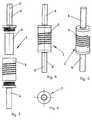
- the first spring element 2is designed as a helical spring with a central cavity 15, while the second spring element 4 is designed rod-shaped and is arranged in the cavity 15.
- the terminal connecting parts 5, 6are also arranged coaxially to the longitudinal axis 3 and have directed against the spring elements 2, 4, depending on the longitudinal axis 3 coaxial threaded piece 16, 17 with an external thread 18.
- the first spring element 2is provided at its axial ends 21 with internal threads 24 mounted in the cavity 15, which are designed to be complementary to the external threads 18, so that the threaded pieces of the connecting parts 5; 6 can be screwed into the first spring element 2.
- each connecting part 5, 6comprises a longitudinal axis 3 arranged coaxially and at the inner end 19 of the connecting part 5, 6 open recess 23 so that the rod-shaped second spring element 4 at its axial ends 22 in the recesses 23 can be accommodated.
- the connecting parts 5, 6are coaxially bar-shaped at their outer end 20.
- This distance L and the length of the non-deformed first spring element 2are dimensioned so that when screwing the threaded pieces 16, 17 in the internal thread 24, the first spring element 2 is stretched axially by a desired length, whereby the damping element 1 receives a bias.
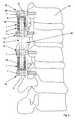
- a device for stabilizing adjacent vertebral bodies(not shown) is shown.
- a plurality of pedicle screws or hooks 12are attached to the pedicles of the vertebrae to be connected such that their central axes 28 are arranged transversely to the longitudinal axis of the spine.
- the receiving means 13 on the pedicle screws or hooks 12are arranged perpendicular to the central axes 28 and formed as channels 26.
- the rod-shaped, outer ends 20 of the connecting parts 5, 6(FIG. 1) can be inserted, so that the damping elements 1 in the channels 26 are axially displaceable before being fixed by means of screws 27 relative to the pedicle screws or hooks 12 become.
- the receiving means 13 on the pedicle screws or hooks 12each comprise two parallel channels 26, so that, for example, a rod-shaped fastening element 7 can be fixed to a pedicle screw or hook 12 in addition to a damping element 1.
- FIG. 3shows a damping element 1 with a first spring element 2 designed as a helical spring, a rod-shaped second spring element 4 and two connection parts 5, 6 arranged coaxially with respect to the longitudinal axis 3.
- FIGS. 4 and 5show a damping element 1 with a first spring element 2 designed as a helical spring and two connecting parts 5, 6 connected coaxially with the first spring element 2 with respect to the longitudinal axis 3.
- FIG. 6shows an embodiment of the damping element 1 according to the invention, which has a circular cross section which is orthogonal to the longitudinal axis 3.
- Other cross-sectional shapesfor example oval or elliptical Cross sections, which favor the implantation of the damping element 1 are also possible.
- a connecting part 5, 6is arranged, wherein the two connecting parts 5, 6 are integral with the first spring element 2 in this embodiment.
- the first connecting part 5is formed as a sleeve 30 with a central bore 32 coaxial with the longitudinal axis 3, while the second connecting part 6 is formed as a coaxial rod to the longitudinal axis 3.
- the second, rod-shaped connecting part 6is arranged at the end 21 of the first spring element 2, where the cavity 15 is axially closed.
- the central bore 32 in the first connection part 5has a diameter D.
- the second connecting part 6is also configured circular-cylindrical and has a diameter d, which in the embodiment of the damping element 1 shown here is the same size as the diameter D of the central bore 32 in the first connecting part 5.
- a longitudinal bar belonging to a device for stabilizing vertebral bodies or the second, rod-shaped connecting part 6 of a further damping element 1can be introduced into the central bore 32.
- the second spring element 4is arranged coaxially to the longitudinal axis 3 in the cavity 15 of the first spring element 2 and has a helical slot 34 in the first spring element 2 complementary helical, elastically deformable elevation 35, which closes the slot 34 in the first spring element 2. Furthermore, the second spring element 4 is provided with a central bore 33 which is coaxial with the longitudinal axis 3 and has the same diameter as the central bore 32 in the sleeve 30.
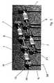
- FIG. 8shows an embodiment of the device 38 according to the invention in an application for stabilizing adjacent vertebral bodies 37.
- a pedicle screw 12is screwed into each of four adjoining vertebral bodies 37.
- the device 38comprises coaxially to the longitudinal axis 3 arranged between one of the outer of the four adjacent vertebrae 37 and the adjacent inner vertebral body 37 acting as a spring element 14 and between the two adjacent inner vertebral bodies 37 a rod-shaped side member 8.
- the acting as a spring elements 14thconsist of damping elements 1, each of which at one of its ends 21 (Fig. 7) comprise a rod-shaped connecting part 6 and at the other end 21 a sleeve 30 (Fig. 7).
- the rod-shaped connecting parts 6serve as fastening elements 7, which are inserted into the receiving means 13 of the two terminal pedicle screws 12 with respect to the device 38 and are detachably connected there to the pedicle screws by means of the locking means 29 designed as screws.
- the connecting parts 5 of the damping elements 1 designed as bushes 30(FIG. 7) are directed against the inner two of the four vertebral bodies 37 to be stabilized.
- a rod-shaped side member 8is used, wherein the longitudinal member 8 is formed so that the fastening elements 7 are formed in the receiving means 13 of the two inner pedicle screws 12 by axial segments of the longitudinal member 8.
- the longitudinal member 8is connected on the one hand by means of the locking means 29 formed as screws of the two inner pedicle screws 12 with the device 38 and on the other hand with its two ends 39, 40 in the central bores 32, 33 in the connecting parts 5 and the second spring elements 4 (FIG ) and releasably blocked there by means of the locking means 31 (FIG. 7).
- the longitudinal axis 3may also be curved or angled in various applications of the device 38 according to the invention.
- FIG. 9shows an embodiment of the device according to the invention, which differs from the embodiment shown in FIG. 8 only in that it two parallel to the longitudinal axes 3 devices 38, each with two axially integral damping elements 1 and each one arranged therebetween longitudinal member 8 includes. Furthermore, five pedicle screws 12 are provided.
Landscapes
- Health & Medical Sciences (AREA)
- Orthopedic Medicine & Surgery (AREA)
- Engineering & Computer Science (AREA)
- General Engineering & Computer Science (AREA)
- Life Sciences & Earth Sciences (AREA)
- Neurology (AREA)
- Surgery (AREA)
- Mechanical Engineering (AREA)
- Molecular Biology (AREA)
- Biomedical Technology (AREA)
- Heart & Thoracic Surgery (AREA)
- Medical Informatics (AREA)
- Nuclear Medicine, Radiotherapy & Molecular Imaging (AREA)
- Animal Behavior & Ethology (AREA)
- General Health & Medical Sciences (AREA)
- Public Health (AREA)
- Veterinary Medicine (AREA)
- Surgical Instruments (AREA)
- Prostheses (AREA)
- Springs (AREA)
- Vibration Prevention Devices (AREA)
- Transition And Organic Metals Composition Catalysts For Addition Polymerization (AREA)
- Materials For Medical Uses (AREA)
- Registering, Tensioning, Guiding Webs, And Rollers Therefor (AREA)
- Control Of Motors That Do Not Use Commutators (AREA)
- Beans For Foods Or Fodder (AREA)
- Orthopedics, Nursing, And Contraception (AREA)
Abstract
Description
Translated fromGermanDie Erfindung bezieht sich auf eine Dämpfungselement, gemäss dem Oberbegriff des Patentanspruchs 1, sowie auf eine Vorrichtung zur Stabilisierung benachbarter Wirbelkörper, gemäss dem Oberbegriff des Patentanspruchs 25.The invention relates to a damping element, according to the preamble of
Aus der
Aus der
Aus der
Erstens müssen das Kunststoffband und die Stützelemente - wie bei einer Perlenkette - in, bzw. zwischen die Bohrungen der bereits implantierten Pedikelschrauben eingefädelt werden, was für den Chirurgen umständlich und zeitraubend ist. Zweitens weist das - bis zu einem gewissen Grade elastische Kunststoffband - keine Vorspannung auf. Da die Länge der Stützkörpers auch bei dieser Vorrichtung fix ist, werden Sollbruchstellen am Stützkörper vorgeschlagen, so dass dieser intraoperativ an die effektive Distanz zwischen beiden betroffenen Pedikelschrauben vom Chirurgen zurechtgeschnitten werden kann. Dies ist für den Chirurgen umständlich und zeitraubend und dürfte in der Regel zu einem zu kurzen Stützelement führen, so dass seine Dämpfungswirkung erst mit einer gewissen Verzögerung eintritt, was natürlich unerwünscht ist.First, the plastic band and the support elements - as in a string of pearls - must be threaded into, or between the holes of the already implanted pedicle screws, which is cumbersome and time-consuming for the surgeon. Second, the - to some extent elastic plastic tape - has no bias. Since the length of the support body is fixed even in this device, predetermined breaking points are proposed on the support body, so that it can be cut by the surgeon intraoperatively to the effective distance between the two affected pedicle screws. This is cumbersome and time-consuming for the surgeon and should usually lead to too short a support element, so that its damping effect occurs only with a certain delay, which of course is undesirable.
Aus der
Hier will die Erfindung Abhilfe schaffen. Der Erfindung liegt die Aufgabe zugrunde, ein kombiniertes, vorgespanntes Zug-Druck-Element zu schaffen, welches zwischen zwei Pedikelschrauben, bzw. Pedikelhaken befestigbar ist und einerseits auf Zug als Federelement mit einer gewissen Federrate und anderseits auf Druck als Dämpfungselement mit einer anderen Federrate wirkt.The invention aims to remedy this situation. The invention has for its object to provide a combined, biased train-pressure element which is fastened between two pedicle screws, or Pedikelhaken and on the one hand acts on train as a spring element with a certain spring rate and on the other hand to pressure as a damping element with a different spring rate ,
Die Erfindung löst die gestellte Aufgabe mit einem Dämpfungselement, welches die Merkmale des Anspruchs 1 aufweist, sowie mit einer Vorrichtung zur Stabilisierung benachbarter Wirbelkörper, welche die Merkmale des Anspruchs 25 aufweist.The invention solves the stated object with a damping element, which has the features of
In der bevorzugten Ausführungsform des erfindungsgemässen Dämpfungselementes ist eines der Federelemente als Druckfeder angeordnet. Bei montiertem Dämpfungselement stehen die an den Enden der Federelemente angeordneten Verbindungsteile an den Enden des als Druckfeder angeordneten Federelementes an, so dass das erste Federelement auf Zug belastet werden kann und vorspannbar ist.In the preferred embodiment of the inventive damping element one of the spring elements is arranged as a compression spring. When mounted damping element arranged at the ends of the spring elements connecting parts are at the ends of the spring element arranged as a compression spring, so that the first spring element can be loaded on train and can be prestressed.
Die durch die Erfindung erreichten Vorteile sind im wesentlichen die folgenden:
- durch Wahl unterschiedlich langer Innenzylinder können die Dämpfungseigenschaften variiert werden.
- die bereits im vormontierten Zustand des Dämpfungselementes vorhandene Vorspannkraft ist klar definiert und kann dem Chirurgen in einer Auswahl zur Verfügung gestellt werden, welche den unterschiedlichen Körpergewichten der Patienten und den unterschiedlichen Indikationen entsprechen; und
- die Dämpfungselemente können nach dem Distrahieren der Wirbelkörper rasch und einfach zwischen die Pedikelschrauben eingelegt und daran fixiert werden.
- by choosing differently long inner cylinder, the damping properties can be varied.
- the already existing in the preassembled state of the damping element biasing force is clearly defined and the surgeon in a selection for Be made available, which correspond to the different body weights of the patients and the different indications; and
- the damping elements can be inserted quickly and easily between the pedicle screws after distraction of the vertebral body and fixed to it.
In einer weiteren Ausführungsform des erfindungsgemässen Dämpfungselementes sind die beiden Verbindungsteile mit den Federelementen lösbar verbindbar. Die Verbindung zwischen den Verbindungsteilen und mindestens einem der Federelemente erfolgt vorzugsweise durch eine Gewindeverbindung. Damit ist erreichbar, dass je nach Anwendungsfall verschiedene, den Bedürfnissen angepasste Verbindungsteile eingesetzt werden können. Zudem bildet das erfindungsgemässe Dämpfungselement ein einheitliches Zug/Druck-Element, dessen Länge variabel einstellbar ist.In a further embodiment of the inventive damping element, the two connecting parts with the spring elements are detachably connectable. The connection between the connecting parts and at least one of the spring elements is preferably effected by a threaded connection. This is achievable that depending on the application, different, adapted to the needs of connecting parts can be used. In addition, the damping element according to the invention forms a uniform tension / compression element whose length is variably adjustable.
In einer anderen Ausführungsform des erfindungsgemässen Dämpfungselementes ist mindestens eines der beiden Verbindungsteile einstückig mit mindestens einem der Federelemente ausgeführt. Durch eine solche Ausgestaltung ist eine kompaktere Bauweise des erfindungsgemässen Dämpfungselementes erreichbar.In another embodiment of the damping element according to the invention, at least one of the two connecting parts is designed in one piece with at least one of the spring elements. By such a configuration, a more compact design of the inventive damping element can be achieved.
Die Verbindungsteile können je nach Anwendung des erfindungsgemässen Dämpfungselementes stabförmig oder als Büchse ausgebildet sein, wobei mindestens ein Verbindungsteil mit einer Büchse mindestens ein Verbindungsteil kreiszylindrische ausgestallet ist, und je ein Verbindungsteil zur Längsachse koaxial an einem Ende der Federelemente angeordnet ist. Die Büchse weist eine zur Längsachse koaxiale Zentralbohrung auf und umfasst vorzugsweise Arretiermittel zur Fixierung eines in der Zentralbohrung eingeführten Stabes. Durch diese Ausgestaltung des Dämpfungselementes ist erreichbar, dass koaxial zur Längsachse ein stabförmiges Befestigungselement oder ein kreiszylindrische Verbindungsteil eines weiteren Dämpfungselementes mit dem als Büchse ausgestalteten Verbindungsteil des ersten Dämpfungselementes verbindbar ist.Depending on the application of the damping element according to the invention, the connecting parts may be rod-shaped or sleeve-shaped, at least one connecting part having a sleeve having at least one connecting part being circular-cylindrical, and one connecting part being arranged coaxially with the longitudinal axis at one end of the spring elements. The sleeve has a central bore coaxial with the longitudinal axis and preferably comprises locking means for fixing a rod inserted in the central bore. By means of this embodiment of the damping element, it can be achieved that a rod-shaped fastening element or a circular-cylindrical connecting part of a further damping element can be connected coaxially with the connecting part of the first damping element designed as a bushing.
Vorzugsweise umfassen die Arretiermittel mindestens eine Schraube, welche quer zur Längsachse in die Büchse einschraubbar ist und zur Fixierung eines in die Zentralbohrung der Büchse eingeführten stabförmigen Teiles dient. Durch Verwendung einer radial nicht über die Büchse hinausragende Stiftschraube als Arretiermittel ist eine kompakte Bauweise des Dämpfungselementes erreichbar, was für die Anwendung des Dämpfungselementes innerhalb einer Vorrichtung zur Stabilisierung von Wirbelkörpern vorteilhaft ist.Preferably, the locking means comprise at least one screw which can be screwed into the sleeve transversely to the longitudinal axis and serves to fix a rod-shaped part inserted into the central bore of the sleeve. By using a radially beyond the sleeve protruding stud than locking means a compact design of the damping element can be achieved, which is for the application of the Damping element is advantageous within a device for stabilizing vertebral bodies.
Die Verbindungsteile an den beiden Enden der Federelemente können je nach Anwendung des Dämpfungselementes beide stabförmig, beide als Büchsen oder eines als Büchse und das Andere stabförmig ausgestaltet sein.Depending on the application of the damping element, the connecting parts at the two ends of the spring elements can be designed in the manner of a rod, both in the form of bushes or one as a bush, and the other rod-shaped.
Bei einer Anwendung eines oder mehrerer erfindungsgemässen Dämpfungselemente innerhalb einer Vorrichtung zur Stabilisierung von benachbarten Wirbelkörpern wird vorzugsweise eines der Verbindungsteile an einer Pedikelschraube oder einem Pedikelhaken fixiert und durch das zweite Verbindungselement mit einem stabförmigen Längsträger verbunden. Dazu eignet sich die Ausgestaltung der Verbindungsteile derart, dass eines der Verbindungsteile als Büchse ausgeführt ist während das zweite Verbindungsteil stabförmig ausgebildet ist. Der Längsträger wird in die Zentralbohrung der Büchse eingeführt und mittels Arretiermittel in der Büchse fixiert, während das stabförmige Verbindungsteil in die üblicherweise als Kanal ausgestalteten Aufnahmemittel an den Pedikelschrauben oder Pedikelhaken einführbar und dort ebenfalls fixierbar ist. Vorzugsweise weist das stabförmig ausgestaltete Verbindungsteil axial eine Länge auf, welche grösser als die Länge der Aufnahmemittel ist, so dass das Dämpfungselement je nach bedarf axial verschoben und justiert werden kann.In an application of one or more inventive damping elements within a device for stabilizing adjacent vertebral bodies, one of the connecting parts is preferably fixed to a pedicle screw or a pedicle hook and connected by the second connecting element with a rod-shaped longitudinal member. For this purpose, the configuration of the connecting parts is such that one of the connecting parts is designed as a sleeve while the second connecting part is rod-shaped. The longitudinal member is inserted into the central bore of the sleeve and fixed by means of locking means in the sleeve, while the rod-shaped connecting part in the usually configured as a channel receiving means to the pedicle screws or Pedikelhaken is inserted and also fixed there. Preferably, the rod-shaped connecting part axially has a length which is greater than the length of the receiving means, so that the damping element can be axially displaced and adjusted as needed.
Zur Vereinfachung einer kombinierten Anwendung von stabförmigen Befestigungselementen, beispielsweise Längsträgern und erfindungsgemässen Dämpfungselementen innerhalb einer Vorrichtung zur Stabilisierung von benachbarten Wirbelkörpern werden der Durchmesser D der Zentralbohrung des als Büchse ausgestalteten Verbindungsteiles und der Durchmesser d des stabförmigen Verbindungsteiles so gewählt, dass D ≅ d ist.To simplify a combined application of rod-shaped fasteners, such as side rails and damping elements according to the invention within a device for stabilizing adjacent vertebral bodies, the diameter D of the central bore of the connecting part designed as a sleeve and the diameter d of the rod-shaped connecting part are selected such that D ≅ d.
In einer Ausführungsform des erfindungsgemässen Dämpfungselementes sind die Federelemente so ausgestaltet, dass sie eine konstante Federrate aufweisen. Damit ist erreichbar, dass bei Entlastung des Dämpfungselementes der Zustand der unbelasteten Federelemente wieder herstellbar ist.In one embodiment of the inventive damping element, the spring elements are designed so that they have a constant spring rate. It is thus achievable that when the damping element is relieved, the state of the unloaded spring elements can be restored.
In einer anderen Ausführungsform des erfindungsgemässen Dämpfungselementes weist dieses einen zur Längsachse orthogonalen, nierenförmigen Querschnitt auf. Die Vorteile einer solchen Ausführung liegen darin, dass bei der Implantation eines oder mehrerer Dämpfungselemente, beispielsweise innerhalb einer Wirbelsäulenfixation, diese mit Berücksichtigung von Wirbelfortsätzen oder anderen Implantatteilen günstiger plazierbar sind.In another embodiment of the damping element according to the invention, this has a kidney-shaped cross-section which is orthogonal to the longitudinal axis. The advantages of such an embodiment are that in the implantation of one or more damping elements, for example, within a spinal fixation, they are cheaper to place with consideration of spinous processes or other implant parts.
In einer weiteren Ausführungsform des erfindungsgemässen Dämpfungselementes ist das zweite Federelement im Innern des ersten Federelementes angeordnet. Vorzugsweise ist das zweite Federelement als Druckfeder ausgebildet, so dass bei zusammengebautem Dämpfungselement eine Vorspannung mindestens des ersten Federelementes erreichbar ist. Ferner ist die Anordnung der beiden Federelemente vorzugsweise konzentrisch. Der Vorteil dieser Ausführungsform liegt ebenfalls in den damit erreichbaren geringen Aussenabmessungen des Dämpfungselementes.In a further embodiment of the inventive damping element, the second spring element is arranged in the interior of the first spring element. Preferably, the second spring element is designed as a compression spring, so that when assembled damping element, a bias of at least the first spring element is reached. Furthermore, the arrangement of the two spring elements is preferably concentric. The advantage of this embodiment is also in the thus achievable small external dimensions of the damping element.
In wiederum einer weiteren Ausführungsform des erfindungsgemässen Dämpfungselementes weist das im Innern des ersten Federelementes angeordnete und als Druckfeder ausgestaltete zweite Federelement eine zur Längsachse koaxiale Zentralbohrung auf, deren Durchmesser vorzugsweise dem Durchmesser der Zentralbohrung in der Büchse entspricht. Dadurch ist eine längere axiale Führung eines in die Zentralbohrungen eingeführten stabförmigen Teiles möglich, wodurch eine höhere Stabilität der Verbindung zwischen dem Dämpfungselement und dem stabförmigen Teil erreichbar ist.In yet another embodiment of the damping element according to the invention, the second spring element arranged in the interior of the first spring element and designed as a compression spring has a central bore coaxial with the longitudinal axis, the diameter of which preferably corresponds to the diameter of the central bore in the bushing. As a result, a longer axial guidance of an inserted into the central bores rod-shaped part is possible, whereby a higher stability of the connection between the damping element and the rod-shaped part can be achieved.
In einer anderen Ausführungsform des erfindungsgemässen Dämpfungselementes ist das erste Federelement als Schraubenfeder ausgestaltet. Der schraubenförmige Schlitz der Schraubenfeder wird vorzugsweise durch eine komplementär schraubenförmige und elastisch deformierbare Erhebung am zweiten Federelement verschlossen. Die Federwendel der Schraubenfeder kann dabei auch mehrgängig ausgestaltet sein. Vorzugsweise ist das zweite Federelement aus einem giessfähigen Material hergestellt, so dass das zweite Federelement in das bereits fertiggestellte erste Federelement eingiessbar ist.In another embodiment of the inventive damping element, the first spring element is designed as a helical spring. The helical slot of the coil spring is preferably closed by a complementary helical and elastically deformable elevation on the second spring element. The spring coil of the coil spring can also be configured more or less. Preferably, the second spring element is made of a castable material, so that the second spring element can be poured into the already completed first spring element.
In einer Ausführungsform des erfindungsgemässen Dämpfungselementes ist das als Druckfeder ausgestaltete Federelement aus einem Polymer, vorzugsweise aus Polycarbonurethan (PCU) hergestellt.In one embodiment of the damping element according to the invention, the spring element designed as a compression spring is made of a polymer, preferably of polycarbonate urethane (PCU).
In einer weiteren Ausführungsform des erfindungsgemässen Dämpfungselementes ist das als Büchse ausgestaltete Verbindungsteil mit dem Federelement einstückig ausgebildet, wodurch eine einfache Bauweise des Dämpfungselementes erreichbar ist. Dabei sind auch Ausgestaltungen des Dämpfungselementes möglich, wo beide Verbindungsteile mit dem ersten Federelement einstückig ausgebildet sind.In a further embodiment of the inventive damping element designed as a sleeve connecting part with the spring element is integrally formed, whereby a simple construction of the damping element can be achieved. In this case, embodiments of the damping element are possible where both connecting parts are integrally formed with the first spring element.
In allen Ausführungsformen des erfindungsgemässen Dämpfungselementes sind die Federkonstante F des ersten Federelementes und die Federkonstante f des zweiten Federelementes voneinander verschieden. Die beiden Federkonstanten F;f können sich dabei um einen Faktor von mindestens 1,2, vorzugsweise mindestens 5 unterscheiden. Dadurch ist der Vorteil erreichbar, dass die Federkräfte des Dämpfungselementes bei Belastung auf Zug oder Druck voneinander verschieden sind. Je nach Anwendungsbereich des Dämpfungselementes können sich die Federkonstanten auch um einen Faktor zwischen 10 und 100 unterscheiden.In all embodiments of the inventive damping element, the spring constant F of the first spring element and the spring constant f of the second spring element are different from each other. The two spring constants F; f may differ by a factor of at least 1.2, preferably at least 5. As a result, the advantage is achieved that the spring forces of the damping element are different from each other under load to train or pressure. Depending on the field of application of the damping element, the spring constants may also differ by a factor between 10 and 100.
In weiteren Ausführungsformen des erfindungsgemässen Dämpfungselementes beträgt die Federrate f des zweiten Dämpfungselementes zwischen 50 N/mm und 5000 N/mm, vorzugsweise zwischen 100 N/mm und 2000 N/mm.In further embodiments of the inventive damping element, the spring rate f of the second damping element is between 50 N / mm and 5000 N / mm, preferably between 100 N / mm and 2000 N / mm.
Weitere vorteilhafte Ausgestaltungen der Erfindung sind in den abhängigen Ansprüchen gekennzeichnet.Further advantageous embodiments of the invention are characterized in the dependent claims.
Die erfindungsgemässe Vorrichtung zur Stabilisierung benachbarter Wirbelkörper umfasst im wesentlichen mehrere, mit verschiedenen Befestigungsmitteln verbindbare Pedikelschrauben oder Pedikelhaken. Zwischen zwei Pedikelschrauben oder Pedikelhaken können als Befestigungsmittel beispielsweise stabförmige Längsträger, Federn oder erfindungsgemässe Dämpfungselemente eingesetzt werden.The device according to the invention for stabilizing adjacent vertebral bodies essentially comprises a plurality of pedicle screws or pedicle hooks connectable with different attachment means. Between two pedicle screws or Pedikelhaken can be used as fastening means, for example, rod-shaped side members, springs or inventive damping elements.
In der erfindungsgemässen Vorrichtung umfassen die Pedikelschrauben oder Pedikelhaken Aufnahmemittel, welche die (vorzugsweise axial verschiebbare) Aufnahme von Befestigungselemente, beispielsweise stabförmigen Längsträgern, respektive der stabförmig ausgebildeten Verbindungsteile an den erfindungsgemässen Dämpfungselementen gestatten. Zur Fixierung der Befestigungselemente in den Aufnahmemitteln können die Pedikelschrauben oder Pedikelhaken Feststellmittel umfassen, welche beispielsweise endständig angeordnet sein können und aus Klemmschrauben oder Klemmuttern bestehen können. Die erfindungsgemässen Vorrichtung ist durch den Einsatz von einerseits rigiden Elementen, wie beispielsweise Längsträger und andererseits dämpfenden Elementen bezüglich ihrer Stabilität an die jeweiligen Bedingungen anpassbar.In the device according to the invention, the pedicle screws or pedicle hooks comprise receiving means, which hold the (preferably axially slidable) receiving fasteners, such as rod-shaped longitudinal members, respectively, allow the rod-shaped connecting parts on the inventive damping elements. To fix the fastening elements in the receiving means, the pedicle screws or Pedikelhaken may comprise locking means, which may for example be arranged terminally and may consist of clamping screws or clamping nuts. The device according to the invention can be adapted to the respective conditions with regard to its stability by the use of rigid elements on the one hand, such as, for example, side members and, on the other hand, damping elements.
In einer Ausführungsform der erfindungsgemässen Vorrichtung umfasst mindestens eine Pedikelschraube oder ein Pedikelhaken Aufnahmemittel, welche zugleich die Aufnahme von zwei parallelen longitudinalen Befestigungselementen gestattet. Auf diese Weise wird ermöglicht, dass ein als Feder wirkendes Element, beispielsweise ein erfindungsgemässes Dämpfungselement zur Befestigung zwischen mindestens einer mit Aufnahmemitteln versehenen Pedikelschraube oder Pedikelhaken und einer weiteren, benachbarten Pedikelschraube oder Pedikelhaken einsetzbar ist.In one embodiment of the device according to the invention, at least one pedicle screw or a pedicle hook comprises receiving means, which at the same time allows the reception of two parallel longitudinal fastening elements. In this way, it is possible that an acting as a spring element, for example, an inventive damping element for attachment between at least one provided with receiving means pedicle screw or Pedikelhaken and another, adjacent pedicle screw or Pedikelhaken is used.
Pedikelschrauben oder Pedikelhaken mit Aufnahmemitteln, welche gestatten, dass zugleich zwei parallele, longitudinale Befestigungselemente mit der Pedikelschraube oder dem Pedikelhaken verbindbar sind, sind beispielsweise aus der
Die Vorspannung des Dämpfungselementes gestattet beispielsweise die Berücksichtigung verschiedener Instabilitäten, Indikation oder des Gewichtes des Patienten. Das Dämpfungselement ist bei einer Extension der damit verbundenen Wirbelsäulenteile auf Druck belastet, während es bei einer Flexion der damit verbundenen Wirbelsäulenteile auf Zug belastet wird. Die Wahl des Federmateriales, beispielsweise ein Polymer, vorzugsweise Polycarbonaturethan (PCU) für das auf Druck belastete Federelement und ein Metall für das auch auf Zug belastete Federelement, die Wahl der geometrischen Abmessungen sowie die eingestellte Vorspannung des auch auf Zug belasteten Federelementes gestatten eine optimale Anpassung der erfindungsgemässen Vorrichtung an die biomechanischen Gegebenheiten bei einem Patienten.The bias of the damping element allows, for example, the consideration of various instabilities, indication or the weight of the patient. The damping element is loaded on an extension of the associated spinal column parts to pressure, while it is loaded in a flexion of the associated spinal column parts to train. The choice of the spring material, such as a polymer, preferably polycarbonate urethane (PCU) for the pressure-loaded spring element and a metal for the loaded also train train spring element, the choice of geometrical dimensions and the set bias of the spring loaded on train spring element allow optimal adaptation the inventive device to the biomechanical conditions in a patient.
Die Vorteile der erfindungsgemässen Vorrichtung sind im wesentlichen die folgenden:
- harmonischer Steifigkeitsübergang vom stabiliserten Wirbelsäulensegment zu den gesunden Wirbelsäulensegementen.
- Die Dämpfungselemente können wahlweise mit rigiden Stäben segementweise kombiniert werden.
- harmonic stiffness transition from the stabilized spinal segment to the healthy spinal segments.
- The damping elements can optionally be combined segementweise with rigid rods.
Die Erfindung und Weiterbildungen der Erfindung werden im folgenden anhand der teilweise schematischen Darstellungen mehrerer Ausführungsbeispiele noch näher erläutert.The invention and further developments of the invention will be explained in more detail below with reference to the partially schematic representations of several embodiments.
Es zeigen:
- Fig. 1 einen Längsschnitt durch ein nicht erfindungsgemässes Dämpfungselement;
- Fig. 2 eine Ansicht einer nicht erfindungsgemässen Vorrichtung zur Stabilisierung benachbarter Wirbelkörper;
- Fig. 3 eine Explosionsdarstellung eines nicht erfindungsgemässen Dämpfungselementes;
- Fig. 4 eine Ansicht eines nicht erfindungsgemässen Dämpfungselementes;
- Fig. 5 eine perspektivische Darstellung eines nicht erfindungsgemässen Dämpfungselementes;
- Fig. 6 eine Aufsicht auf ein nicht erfindungsgemässes Dämpfungselement;
- Fig. 7 einen Längsschnitt durch eine Ausführungsform des erfindungsgemässen Dämpfungselementes;
- Fig. 8 eine Ansicht einer Ausführungsform der erfindungsgemässen Vorrichtung bei ihrer Anwendung zur Stabilisierung von benachbarten Wirbelkörpern; und
- Fig. 9 eine perspektivische Ansicht einer Ausführungsform der erfindungsgemässen Vorrichtung.
- 1 shows a longitudinal section through a not according to the invention damping element.
- FIG. 2 shows a view of a device according to the invention for stabilizing adjacent vertebral bodies; FIG.
- 3 is an exploded view of a damping element not according to the invention;
- 4 shows a view of a damping element not according to the invention;
- 5 is a perspective view of a non-inventive damping element.
- 6 is a plan view of a non-inventive damping element.
- 7 shows a longitudinal section through an embodiment of the inventive damping element.
- 8 shows a view of an embodiment of the device according to the invention in its application for stabilizing adjacent vertebral bodies; and
- Fig. 9 is a perspective view of an embodiment of the inventive device.
Die Fig. 1 zeigt ein Dämpfungselement 1 mit zwei zur Längsachse 3 konzentrisch angeordneten Federelementen 2;4. Das erste Federelement 2 ist als Schraubenfeder mit einem zentralen Hohlraum 15 ausgeführt, während das zweite Federelement 4 stabförmig ausgestaltet ist und im Hohlraum 15 angeordnet ist. Die endständigen Verbindungsteile 5;6 sind ebenfalls zur Längsachse 3 koaxial angeordnet und weisen gegen die Federelemente 2;4 gerichtet, je ein zur Längsachse 3 koaxiales Gewindestück 16;17 mit einem Aussengewinde 18 auf. Das erste Federelement 2 ist an seinen axialen Enden 21 mit im Hohlraum 15 angebrachten Innengewinden 24 versehen, welche zu den Aussengewinden 18 komplementär ausgestaltet sind, so dass die Gewindestücke der Verbindungsteile 5;6 in das erste Federelement 2 einschraubbar sind. Ferner umfasst jedes Verbindungsteil 5;6 eine zur Längsachse 3 koaxial angeordnete und am inneren Ende 19 des Verbindungsteils 5;6 offene Vertiefung 23, so dass das stabförmig ausgebildete zweite Federelement 4 an seinen axialen Enden 22 in den Vertiefungen 23 aufnehmbar ist. Ferner sind die Verbindungsteile 5;6 an ihren äusseren Ende 20 koaxial stabförmig ausgebildet. Bei montiertem Dämpfungselement 1 liegen die Enden 22 der zweiten Feder 4 an den zur Längsachse 3 orthogonalen Stirnflächen 25 der Vertiefungen 23 auf, so dass die Verbindungsteile 5;6 zwischen diesen Stirnflächen 25 einen Abstand L aufweisen. Dieser Abstand L sowie die Länge des nicht deformierten ersten Federelementes 2 sind so bemessen, dass beim Einschrauben der Gewindestücke 16;17 in die Innengewinde 24 das erste Federelement 2 axial um eine gewünschte Länge gedehnt wird, wodurch das Dämpfungselement 1 eine Vorspannung erhält.1 shows a damping
In Fig. 2 ist eine Vorrichtung zur Stabilisierung benachbarter Wirbelkörper (nicht gezeichnet) dargestellt. Mehrere Pedikelschrauben oder -haken 12 sind so an den Pedikeln der zu verbindenden Wirbelkörper befestigt, dass ihre Zentralachsen 28 quer zur Wirbelsäulenlängsachse angeordnet sind. Die Aufnahmemittel 13 an den Pedikelschrauben oder-haken 12 sind zu den Zentralachsen 28 senkrecht angeordnet und als Kanäle 26 ausgebildet. In diesen Kanälen 26 sind die stabförmigen, äusseren Enden 20 der Verbindungsteile 5;6 (Fig. 1) einführbar, so dass die Dämpfungselemente 1 in den Kanälen 26 axial verschiebbar sind, bevor sie mittels Schrauben 27 relativ zu den Pedikelschrauben oder -haken 12 fixiert werden. Die Aufnahmemittel 13 an den Pedikelschrauben oder -haken 12 umfassen je zwei parallele Kanäle 26, so dass an einer Pedikelschraube oder -haken 12 neben einem Dämpfungselement 1 beispielsweise ein stabförmiges Befestigungselement 7 fixierbar ist.In Fig. 2, a device for stabilizing adjacent vertebral bodies (not shown) is shown. A plurality of pedicle screws or hooks 12 are attached to the pedicles of the vertebrae to be connected such that their
Fig. 3 zeigt ein Dämpfungselement 1 mit einem als Schraubenfeder ausgestalteten, ersten Federelement 2, einem stabförmig ausgebildeten, zweiten Federelement 4 und zwei zur Längsachse 3 koaxial angeordneten Verbindungsteilen 5;6.3 shows a damping
Fig. 4 und 5 zeigen ein Dämpfungselement 1 mit einem als Schraubenfeder ausgestalteten ersten Federelement 2 und zwei zur Längsachse 3 koaxial mit dem ersten Federelement 2 verbundenen Verbindungsteilen 5;6.4 and 5 show a damping
In Fig. 6 ist eine Ausführungsform des erfindungsgemässen Dämpfungselementes 1 dargestellt, welches einen zur Längsachse 3 orthogonalen, kreisförmigen Querschnitt aufweist. Andere Querschnittsformen, beispielsweise ovale oder elliptische Querschnitte, welche die Implantation des Dämpfungselementes 1 begünstigen sind ebenfalls möglich.FIG. 6 shows an embodiment of the damping
In Fig. 7 ist eine Ausführungsform des erfindungsgemässen Dämpfungselementes 1 dargestellt, welches eine zur Längsachse 3 koaxial angeordnete, kreiszylindrische Schraubenfeder als erstes Federelement 2 umfasst. Dieses erste Federelement 2 weist einen schraubenlinienförmigen Schlitz 34 auf und ist mit einem zur Längsachse 3 koaxialen, nur an einem Ende 21 des ersten Federelementes 2 offenen Hohlraum 15 ausgestattet. An jedem der beiden axialen Enden 21 ist ein Verbindungsteil 5;6 angeordnet, wobei die beiden Verbindungsteile 5;6 in dieser Ausführungsform mit dem ersten Federelement 2 einstückig sind. Das erste Verbindungsteil 5 ist als Büchse 30 mit einer zur Längsachse 3 koaxialen Zentralbohrung 32 ausgebildet, während das zweite Verbindungsteil 6 als ebenfalls zur Längsachse 3 koaxialer Stab ausgebildet ist. Das zweite, stabförmige Verbindungsteil 6 ist an dem Ende 21 des ersten Federelementes 2 angeordnet, wo der Hohlraum 15 axial geschlossen ist. Die Zentralbohrung 32 im ersten Verbindungsteil 5 weist einen Durchmesser D auf. Das zweite Verbindungsteil 6 ist ebenfalls kreiszylindrisch ausgestaltet und weist einen Durchmesser d auf, welcher in der hier dargestellten Ausführungsform des Dämpfungselementes 1 gleich gross wie der Durchmesser D der Zentralbohrung 32 im ersten Verbindungsteil 5 ist. Somit lässt sich beispielsweise ein zu einer Vorrichtung zur Stabilisierung von Wirbelkörpern gehörender Längsstab oder das zweite, stabförmige Verbindungsteil 6 eines weiteren Dämpfungselementes 1 in die Zentralbohrung 32 einführen. Mittels Arretiermitteln 31, welche in der hier dargestellten Ausführungsform des Dämpfungselementes 1 als quer zur Längsachse 3 in die Büchse 30 einschraubbare Stiftschraube ausgebildet sind, ist ein solcher in die Zentralbohrung 32 eingeführter Stab fixierbar. Das zweite Federelement 4 ist koaxial zur Längsachse 3 im Hohlraum 15 des ersten Federelementes 2 angeordnet und weist eine zum schraubenlinienartigen Schlitz 34 im ersten Federelement 2 komplementäre schraubenlinienartige, elastisch deformierbare Erhebung 35 auf, welche den Schlitz 34 im ersten Federelement 2 verschliesst. Ferner ist das zweite Federelement 4 mit einer zur Längsachse 3 koaxialen Zentralbohrung 33 ausgestattet, welche denselben Durchmesser aufweist wie die Zentralbohrung 32 in der Büchse 30.In Fig. 7, an embodiment of the inventive damping
Fig. 8 zeigt eine Ausführungsform der erfindungsgemässen Vorrichtung 38 in einer Anwendung zur Stabilisierung von benachbarten Wirbelkörpern 37. In vier aneinandergrenzenden Wirbelkörpern 37 ist je eine Pedikelschraube 12 eingeschraubt. Die Vorrichtung 38 umfasst koaxial zur Längsachse 3 angeordnet jeweils zwischen einem der äusseren der vier aneinandergrenzenden Wirbelkörper 37 und dem benachbarten inneren Wirbelkörper 37 ein als Feder wirkendes Element 14 sowie zwischen den beiden benachbarten inneren Wirbelkörpern 37 einen stabförmigen Längsträger 8. Die als Feder wirkenden Elemente 14 bestehen aus Dämpfungselementen 1, welche je an einem ihrer Enden 21 (Fig. 7) ein stabförmiges Verbindungsteil 6 und am anderen Ende 21 eine Büchse 30 (Fig. 7) umfassen. Die stabförmigen Verbindungsteile 6 dienen als Befestigungselemente 7, welche in die Aufnahmemittel 13 der beiden bezüglich der Vorrichtung 38 endständigen Pedikelschrauben 12 eingeführt sind und dort mittels der als Schrauben ausgeführten Feststellmittel 29 mit den Pedikelschrauben lösbar verbunden sind. Die als Büchsen 30 (Fig. 7) ausgeführten Verbindungsteile 5 der Dämpfungselemente 1 sind gegen die inneren beiden der vier zu stabilisierenden Wirbelkörper 37 gerichtet. Zwischen den beiden Dämpfungselementen 1 ist ein stabförmiger Längsträger 8 eingesetzt, wobei der Längsträger 8 so ausgebildet ist, dass die Befestigungselemente 7 in den Aufnahmemitteln 13 der beiden inneren Pedikelschrauben 12 durch axiale Segmente des Längsträgers 8 gebildet werden. Der Längsträger 8 ist einerseits mittels der als Schrauben ausgebildeten Feststellmittel 29 der beiden inneren Pedikelschrauben 12 mit der Vorrichtung 38 verbunden und andererseits mit seinen beiden Enden 39;40 in die Zentralbohrungen 32;33 in den Verbindungsteilen 5 und den zweiten Federelementen 4 (Fig. 7) eingeführt und dort mittels der Arretiermittel 31 (Fig. 7) lösbar blockiert. Je nach Anwendungsfall sind auch andere zur Längsachse 3 koaxiale Kombinationen von Längsträger 8 und Dämpfungselementen 1 möglich. Anstelle eines Längsträgers 8 können mehrere Längsträger 8 eingesetzt werden oder der oder die Längsträger 8 können durch Verbindungsteile 6 an einem oder mehreren Dämpfungselementen 1, welche in diesem Fall eine axial ausreichende Länge aufweisen müssen, ersetzt sein. Die Längsachse 3 kann bei verschiedenen Anwendungen der erfindungsgemässen Vorrichtung 38 auch gekrümmt oder abgewinkelt sein.FIG. 8 shows an embodiment of the
Fig. 9 zeigt eine Ausführungsform der erfindungsgemässen Vorrichtung, welche sich von der in Fig. 8 dargestellten Ausführungsform nur dadurch unterscheidet, dass sie zwei zu den Längsachsen 3 parallele Vorrichtungen 38 mit je zwei axial enständigen Dämpfungselementen 1 und je einem dazwischenliegend angeordneten Längsträger 8 umfasst. Ferner sind je fünf Pedikelschrauben 12 vorgesehen.FIG. 9 shows an embodiment of the device according to the invention, which differs from the embodiment shown in FIG. 8 only in that it two parallel to the
Claims (29)
- A damping element (1) which is fixable between two pedicle screws, respectively pedicle hooks comprising:(a) two spring elements (2, 4) coaxial with or parallel to a longitudinal axis (3) and two axially end-situated connectors (5, 6), where(b) the first spring element (2) exhibits a spring rate F,(c) the second spring element (4) exhibits a spring rate f,(d) the spring rates F and f are different,
characterized in that(e) at least one connector (5) comprises a bush (30) fitted with a central borehole (32) which is coaxial with the longitudinal axis (3); said bush (30) being connectable to a bar-shaped fixation element or with another damping element; and(f) the central borehole (32) in the bush (30) exhibits an internal diameter D and that the second connector (6) is circular-cylindrical and exhibits an external diameter d ≅ D. - Damping element (1) as claimed in claim 1,characterized in that the connectors (5, 6) may be so linked to the spring elements (2, 4) that at least one of the spring elements (2, 4) is connected to the connectors (5, 6).
- Damping element (1) as claimed in claim 1,characterized in that at least one of the connectors (5, 6) is integral with at least one of the spring elements (2, 4).
- Damping element (1) as claimed in one of claims 1 through 3,characterized in that locking means (31) to lock a bar inserted into the central borehole (32) are configured at the bush (30).
- Damping element (1) as claimed in one of claims 1 through 4,characterized in that at least one of the connectors (5, 6) is bar-shaped.
- Damping element (1) as claimed in claim 4 or 5,characterized in that the locking means (31) include at least a screw which can be screwed orthogonally to the longitudinal axis (3) into the bush (30).
- Damping element (1) as claimed in one of claims 1 through 6,characterized in that the spring elements (2, 4) are configured coaxially with the longitudinal axis (3).
- Damping element (1) as claimed in one of claims 1 through 7,characterized in that at least one of the spring elements (2, 4) is prestressed.
- Damping element (1) as claimed in one of claims 1 through 8,characterized in that the spring elements (2, 4) exhibit constant spring rates F, f.
- Damping element (1) as claimed in one of claims 1 through 9,characterized in that it exhibits a kidney-shaped cross-section perpendicularly to the longitudinal axis (3).
- Damping element (1) as claimed in one of claims 1 through 10,characterized in that one spring element (4) is designed as a compression spring.
- Damping element (1) as claimed in one of claims 1 through 11,characterized in that the second spring element (4) is configured inside the first spring element (2).
- Damping element (1) as claimed in claim 12,characterized in that the second spring element (4) is fitted with a central borehole (33) which is coaxial with the longitudinal axis (3).
- Damping element (1) as claimed in one of claims 1 through 13,characterized in that the first spring element (2) is designed as a helical spring and comprises a helical slot (34).
- Damping element (1) as claimed in claim 14,characterized in that the second spring element (4) comprises an elastically deforming elevation (35) which is complementary to the helical slot (34) at the first spring element (2) and which seals off the slot (34).
- Damping element (1) as claimed in one of claims 1 through 15,characterized in that a spring element (2, 4) is fitted with a multiple spring coil.
- Damping element (1) as claimed in one of claims 11 through 16,characterized in that the spring element (4) acting as a compression spring is made of a polymer, preferably polycarbonate urethane (PCU).
- Damping element (1) as claimed in one of claims 1 through 16,characterized in that the second spring element (4) is integral with one of the connectors (5, 6).
- Damping element (1) as claimed in one of claims 4 through 18,characterized in that the bush (30) is integral with the first spring element (2).
- Damping element (1) as claimed in one of claims 1 through 19,characterized in that the first spring element (2) is integral with both connectors (5, 6).
- Damping element (1) as claimed in one of claims 1 through 20,characterized in that the two spring constants F, f differ by at least the factor 1,2, preferably at least by the factor 5.
- Damping element (1) as claimed in claim 21,characterized in that the two spring constants F, f differ by a factor between 10 and 100.
- Damping element (1) as claimed in one of claims 1 through 22,characterized in that the spring rate f of the second spring element (4) is between 50 N/mm and 5000 N/mm.
- Damping element (1) as claimed in claim 23,characterized in that the spring rate f of the second spring element (4) is between 100 N/mm and 2000 N/mm.
- A device stabilizing adjacent vertebras, comprising a damping element (1) as claimed in one of claims 1 through 24, further(a) N pedicle screws (12) or pedicle hooks, where N ≥ 3 and where(b) each pedicle screw (12) or pedicle hook comprises receiving means (13) receiving longitudinal affixation means (7),
characterized in that(c) at least one damping element (1) is inserted between two adjacent pedicle screws (12) or pedicle hooks. - Device as claimed in claim 25,characterized in that the pedicle screws (12) or pedicle hooks comprise locking means (29) which detachably lock the affixation means (7) into the receiving means (13).
- Device as claimed in either of claims 25 and 26,characterized in that a bar-shaped connector (5, 6) of a damping element (1) acting as an affixation means (7) is detachably locked in the receiving means (13).
- Device as claimed in claim 27,characterized in that the bar-shaped connector (5, 6) is displaceably received parallel to the longitudinal axis (3) in the receiving means (23).
- Device as claimed in one of claims 25 through 28,characterized in that at least one pedicle screw or one pedicle hook (12) comprises receiving means (13) simultaneously permitting receiving two parallel affixation elements (7).
Priority Applications (1)
| Application Number | Priority Date | Filing Date | Title |
|---|---|---|---|
| EP07021854AEP1880684A3 (en) | 2001-12-07 | 2002-03-28 | Device for stabilisation of adjacent vertebrae with damping element |
Applications Claiming Priority (3)
| Application Number | Priority Date | Filing Date | Title |
|---|---|---|---|
| PCT/CH2001/000705WO2003047441A1 (en) | 2001-12-07 | 2001-12-07 | Damping element |
| WOPCT/CH01/00705 | 2001-12-07 | ||
| PCT/CH2002/000180WO2003047442A1 (en) | 2001-12-07 | 2002-03-28 | Damping element and device for stabilisation of adjacent vertebral bodies |
Related Child Applications (1)
| Application Number | Title | Priority Date | Filing Date |
|---|---|---|---|
| EP07021854ADivisionEP1880684A3 (en) | 2001-12-07 | 2002-03-28 | Device for stabilisation of adjacent vertebrae with damping element |
Publications (2)
| Publication Number | Publication Date |
|---|---|
| EP1450708A1 EP1450708A1 (en) | 2004-09-01 |
| EP1450708B1true EP1450708B1 (en) | 2007-11-14 |
Family
ID=4358270
Family Applications (3)
| Application Number | Title | Priority Date | Filing Date |
|---|---|---|---|
| EP01274864AExpired - LifetimeEP1450707B1 (en) | 2001-12-07 | 2001-12-07 | Damping element for the spine |
| EP07021854AWithdrawnEP1880684A3 (en) | 2001-12-07 | 2002-03-28 | Device for stabilisation of adjacent vertebrae with damping element |
| EP02708113AExpired - LifetimeEP1450708B1 (en) | 2001-12-07 | 2002-03-28 | Damping element and device for stabilisation of adjacent vertebral bodies |
Family Applications Before (2)
| Application Number | Title | Priority Date | Filing Date |
|---|---|---|---|
| EP01274864AExpired - LifetimeEP1450707B1 (en) | 2001-12-07 | 2001-12-07 | Damping element for the spine |
| EP07021854AWithdrawnEP1880684A3 (en) | 2001-12-07 | 2002-03-28 | Device for stabilisation of adjacent vertebrae with damping element |
Country Status (19)
| Country | Link |
|---|---|
| US (3) | US7329258B2 (en) |
| EP (3) | EP1450707B1 (en) |
| JP (3) | JP4299669B2 (en) |
| KR (2) | KR20040077670A (en) |
| CN (2) | CN1578644A (en) |
| AT (2) | ATE373994T1 (en) |
| AU (2) | AU2002218099B2 (en) |
| BR (2) | BR0117188A (en) |
| CA (2) | CA2469005A1 (en) |
| CZ (1) | CZ2004691A3 (en) |
| DE (2) | DE50113074D1 (en) |
| ES (2) | ES2293963T3 (en) |
| HU (2) | HUP0402275A2 (en) |
| IL (2) | IL162363A0 (en) |
| MX (1) | MXPA04005398A (en) |
| NO (1) | NO20042859L (en) |
| NZ (2) | NZ533301A (en) |
| RU (1) | RU2004120706A (en) |
| WO (2) | WO2003047441A1 (en) |
Families Citing this family (275)
| Publication number | Priority date | Publication date | Assignee | Title |
|---|---|---|---|---|
| FR2812186B1 (en)* | 2000-07-25 | 2003-02-28 | Spine Next Sa | FLEXIBLE CONNECTION PIECE FOR SPINAL STABILIZATION |
| FR2812185B1 (en)* | 2000-07-25 | 2003-02-28 | Spine Next Sa | SEMI-RIGID CONNECTION PIECE FOR RACHIS STABILIZATION |
| US7833250B2 (en) | 2004-11-10 | 2010-11-16 | Jackson Roger P | Polyaxial bone screw with helically wound capture connection |
| US7862587B2 (en) | 2004-02-27 | 2011-01-04 | Jackson Roger P | Dynamic stabilization assemblies, tool set and method |
| US10729469B2 (en)* | 2006-01-09 | 2020-08-04 | Roger P. Jackson | Flexible spinal stabilization assembly with spacer having off-axis core member |
| US8353932B2 (en) | 2005-09-30 | 2013-01-15 | Jackson Roger P | Polyaxial bone anchor assembly with one-piece closure, pressure insert and plastic elongate member |
| US8292926B2 (en) | 2005-09-30 | 2012-10-23 | Jackson Roger P | Dynamic stabilization connecting member with elastic core and outer sleeve |
| US10258382B2 (en) | 2007-01-18 | 2019-04-16 | Roger P. Jackson | Rod-cord dynamic connection assemblies with slidable bone anchor attachment members along the cord |
| US20160242816A9 (en)* | 2001-05-09 | 2016-08-25 | Roger P. Jackson | Dynamic spinal stabilization assembly with elastic bumpers and locking limited travel closure mechanisms |
| FR2827498B1 (en)* | 2001-07-18 | 2004-05-14 | Frederic Fortin | FLEXIBLE VERTEBRAL CONNECTION DEVICE CONSISTING OF PALLIANT ELEMENTS OF THE RACHIS |
| FR2843538B1 (en)* | 2002-08-13 | 2005-08-12 | Frederic Fortin | DEVICE FOR DISTRACTING AND DAMPING ADJUSTABLE TO THE GROWTH OF THE RACHIS |
| US8876868B2 (en) | 2002-09-06 | 2014-11-04 | Roger P. Jackson | Helical guide and advancement flange with radially loaded lip |
| US7887539B2 (en) | 2003-01-24 | 2011-02-15 | Depuy Spine, Inc. | Spinal rod approximators |
| US7621918B2 (en) | 2004-11-23 | 2009-11-24 | Jackson Roger P | Spinal fixation tool set and method |
| US7713287B2 (en)* | 2003-05-02 | 2010-05-11 | Applied Spine Technologies, Inc. | Dynamic spine stabilizer |
| US20050171543A1 (en)* | 2003-05-02 | 2005-08-04 | Timm Jens P. | Spine stabilization systems and associated devices, assemblies and methods |
| CA2524145A1 (en) | 2003-05-02 | 2004-11-18 | Yale University | Dynamic spine stabilizer |
| US7377923B2 (en) | 2003-05-22 | 2008-05-27 | Alphatec Spine, Inc. | Variable angle spinal screw assembly |
| JP5078355B2 (en)* | 2003-05-23 | 2012-11-21 | グローバス メディカル インコーポレイティッド | Spine stabilization system |
| DE10327358A1 (en)* | 2003-06-16 | 2005-01-05 | Ulrich Gmbh & Co. Kg | Implant for correction and stabilization of the spine |
| US8092500B2 (en)* | 2007-05-01 | 2012-01-10 | Jackson Roger P | Dynamic stabilization connecting member with floating core, compression spacer and over-mold |
| US8926670B2 (en) | 2003-06-18 | 2015-01-06 | Roger P. Jackson | Polyaxial bone screw assembly |
| US8366753B2 (en) | 2003-06-18 | 2013-02-05 | Jackson Roger P | Polyaxial bone screw assembly with fixed retaining structure |
| US7967850B2 (en) | 2003-06-18 | 2011-06-28 | Jackson Roger P | Polyaxial bone anchor with helical capture connection, insert and dual locking assembly |
| US7766915B2 (en) | 2004-02-27 | 2010-08-03 | Jackson Roger P | Dynamic fixation assemblies with inner core and outer coil-like member |
| US7776067B2 (en) | 2005-05-27 | 2010-08-17 | Jackson Roger P | Polyaxial bone screw with shank articulation pressure insert and method |
| BRPI0412565A (en)* | 2003-07-15 | 2006-09-19 | Sasol Tech Pty Ltd | process for producing gaseous and optionally gaseous reactant liquids |
| US20050203513A1 (en)* | 2003-09-24 | 2005-09-15 | Tae-Ahn Jahng | Spinal stabilization device |
| US7137985B2 (en)* | 2003-09-24 | 2006-11-21 | N Spine, Inc. | Marking and guidance method and system for flexible fixation of a spine |
| US8979900B2 (en) | 2003-09-24 | 2015-03-17 | DePuy Synthes Products, LLC | Spinal stabilization device |
| US7815665B2 (en)* | 2003-09-24 | 2010-10-19 | N Spine, Inc. | Adjustable spinal stabilization system |
| CN100435746C (en)* | 2003-09-29 | 2008-11-26 | 斯恩蒂斯有限公司 | Device for elastically stabilizing vertebral bodies |
| WO2005030067A1 (en)* | 2003-09-29 | 2005-04-07 | Synthes Gmbh | Damping element |
| DE102004021861A1 (en) | 2004-05-04 | 2005-11-24 | Biedermann Motech Gmbh | Implant for temporary or permanent replacement of vertebra or intervertebral disk, comprising solid central element and outer elements with openings |
| DE502004004126D1 (en)* | 2003-10-17 | 2007-08-02 | Biedermann Motech Gmbh | Rod-shaped element for connecting bone anchoring elements, and stabilizing device with such a rod-shaped element |
| JP2007508085A (en)* | 2003-10-17 | 2007-04-05 | ヴィーダーマン モテッヒ ゲーエムベーハー | Flexible implant |
| DE10348329B3 (en)* | 2003-10-17 | 2005-02-17 | Biedermann Motech Gmbh | Rod-shaped element used in spinal column and accident surgery for connecting two bone-anchoring elements comprises a rigid section and an elastic section that are made in one piece |
| CN1897884B (en)* | 2003-11-07 | 2010-05-05 | 比德曼莫泰赫有限公司 | Bone anchoring element and stabilization device for bones or vertebrae comprising a bone anchoring element of this type |
| US8632570B2 (en) | 2003-11-07 | 2014-01-21 | Biedermann Technologies Gmbh & Co. Kg | Stabilization device for bones comprising a spring element and manufacturing method for said spring element |
| US7217291B2 (en)* | 2003-12-08 | 2007-05-15 | St. Francis Medical Technologies, Inc. | System and method for replacing degenerated spinal disks |
| US7553320B2 (en)* | 2003-12-10 | 2009-06-30 | Warsaw Orthopedic, Inc. | Method and apparatus for replacing the function of facet joints |
| US7179261B2 (en) | 2003-12-16 | 2007-02-20 | Depuy Spine, Inc. | Percutaneous access devices and bone anchor assemblies |
| US11419642B2 (en) | 2003-12-16 | 2022-08-23 | Medos International Sarl | Percutaneous access devices and bone anchor assemblies |
| US7527638B2 (en) | 2003-12-16 | 2009-05-05 | Depuy Spine, Inc. | Methods and devices for minimally invasive spinal fixation element placement |
| FR2865375B1 (en)* | 2004-01-27 | 2006-12-15 | Medicrea International | MATERIAL OF VERTEBRAL OSTEOSYNTHESIS |
| US7815664B2 (en)* | 2005-01-04 | 2010-10-19 | Warsaw Orthopedic, Inc. | Systems and methods for spinal stabilization with flexible elements |
| US8029548B2 (en) | 2008-05-05 | 2011-10-04 | Warsaw Orthopedic, Inc. | Flexible spinal stabilization element and system |
| US11241261B2 (en) | 2005-09-30 | 2022-02-08 | Roger P Jackson | Apparatus and method for soft spinal stabilization using a tensionable cord and releasable end structure |
| US7160300B2 (en) | 2004-02-27 | 2007-01-09 | Jackson Roger P | Orthopedic implant rod reduction tool set and method |
| US8152810B2 (en) | 2004-11-23 | 2012-04-10 | Jackson Roger P | Spinal fixation tool set and method |
| JP2007525274A (en) | 2004-02-27 | 2007-09-06 | ロジャー・ピー・ジャクソン | Orthopedic implant rod reduction instrument set and method |
| DE102004011685A1 (en)* | 2004-03-09 | 2005-09-29 | Biedermann Motech Gmbh | Spine supporting element, comprising spiraled grooves at outer surface and three plain areas |
| FR2868285B1 (en)* | 2004-03-30 | 2006-11-24 | Scient X Sa | INTERVERTEBRAL CONNECTION DEVICE WITH CONTROLLED MULTIDIRECTIONAL MOVEMENTS |
| US7833256B2 (en)* | 2004-04-16 | 2010-11-16 | Biedermann Motech Gmbh | Elastic element for the use in a stabilization device for bones and vertebrae and method for the manufacture of such elastic element |
| FR2869523A1 (en)* | 2004-04-28 | 2005-11-04 | Frederic Fortin | FLEXIBLE AND MODULAR VERTEBRAL CONNECTION DEVICE HAVING AN ADJUSTABLE ELEMENT FOR WORKING MULTIDIRECTIONALLY |
| KR101276414B1 (en)* | 2004-05-04 | 2013-06-19 | 비이더만 테크놀로지스 게엠베하 & 코. 카게 | Flexible space holder |
| US7500972B2 (en)* | 2004-05-07 | 2009-03-10 | Ethicon Endo-Surgery, Inc. | Device for alternately holding, or effecting relative longitudinal movement, of members of a medical instrument |
| FR2870718B1 (en)* | 2004-05-25 | 2006-09-22 | Spine Next Sa | TREATMENT ASSEMBLY FOR THE DEGENERATION OF AN INTERVERTEBRAL DISC |
| US8858599B2 (en)* | 2004-06-09 | 2014-10-14 | Warsaw Orthopedic, Inc. | Systems and methods for flexible spinal stabilization |
| DE102004040886A1 (en)* | 2004-08-24 | 2006-03-02 | Volkswagen Ag | Operating device for a motor vehicle |
| US7651502B2 (en) | 2004-09-24 | 2010-01-26 | Jackson Roger P | Spinal fixation tool set and method for rod reduction and fastener insertion |
| US20060085076A1 (en)* | 2004-10-15 | 2006-04-20 | Manoj Krishna | Posterior spinal arthroplasty-development of a new posteriorly inserted artificial disc and an artificial facet joint |
| US20070239159A1 (en)* | 2005-07-22 | 2007-10-11 | Vertiflex, Inc. | Systems and methods for stabilization of bone structures |
| WO2009042489A2 (en)* | 2004-10-20 | 2009-04-02 | Vertiflex, Inc. | Dynamic rod |
| US7935134B2 (en)* | 2004-10-20 | 2011-05-03 | Exactech, Inc. | Systems and methods for stabilization of bone structures |
| US8267969B2 (en) | 2004-10-20 | 2012-09-18 | Exactech, Inc. | Screw systems and methods for use in stabilization of bone structures |
| US8226690B2 (en)* | 2005-07-22 | 2012-07-24 | The Board Of Trustees Of The Leland Stanford Junior University | Systems and methods for stabilization of bone structures |
| US8025680B2 (en)* | 2004-10-20 | 2011-09-27 | Exactech, Inc. | Systems and methods for posterior dynamic stabilization of the spine |
| US8162985B2 (en) | 2004-10-20 | 2012-04-24 | The Board Of Trustees Of The Leland Stanford Junior University | Systems and methods for posterior dynamic stabilization of the spine |
| US20060265074A1 (en) | 2004-10-21 | 2006-11-23 | Manoj Krishna | Posterior spinal arthroplasty-development of a new posteriorly inserted artificial disc, a new anteriorly inserted artifical disc and an artificial facet joint |
| AU2005302633A1 (en)* | 2004-10-28 | 2006-05-11 | Axial Biotech, Inc. | Apparatus and method for concave scoliosis expansion |
| US8926672B2 (en) | 2004-11-10 | 2015-01-06 | Roger P. Jackson | Splay control closure for open bone anchor |
| US9168069B2 (en) | 2009-06-15 | 2015-10-27 | Roger P. Jackson | Polyaxial bone anchor with pop-on shank and winged insert with lower skirt for engaging a friction fit retainer |
| US9216041B2 (en) | 2009-06-15 | 2015-12-22 | Roger P. Jackson | Spinal connecting members with tensioned cords and rigid sleeves for engaging compression inserts |
| US8444681B2 (en) | 2009-06-15 | 2013-05-21 | Roger P. Jackson | Polyaxial bone anchor with pop-on shank, friction fit retainer and winged insert |
| WO2006057837A1 (en) | 2004-11-23 | 2006-06-01 | Jackson Roger P | Spinal fixation tool attachment structure |
| US9980753B2 (en) | 2009-06-15 | 2018-05-29 | Roger P Jackson | pivotal anchor with snap-in-place insert having rotation blocking extensions |
| WO2006058221A2 (en) | 2004-11-24 | 2006-06-01 | Abdou Samy M | Devices and methods for inter-vertebral orthopedic device placement |
| WO2006066053A1 (en)* | 2004-12-15 | 2006-06-22 | Stryker Spine | Spinal rods having segments of different elastic properties and methods of using them |
| US20060149242A1 (en)* | 2004-12-17 | 2006-07-06 | Gary Kraus | Spinal stabilization systems supplemented with diagnostically opaque materials |
| EP1719468A1 (en)* | 2004-12-17 | 2006-11-08 | Zimmer GmbH | Intervertebral stabilization system |
| US20060229613A1 (en)* | 2004-12-31 | 2006-10-12 | Timm Jens P | Sheath assembly for spinal stabilization device |
| US7604654B2 (en) | 2005-02-22 | 2009-10-20 | Stryker Spine | Apparatus and method for dynamic vertebral stabilization |
| US7901437B2 (en) | 2007-01-26 | 2011-03-08 | Jackson Roger P | Dynamic stabilization member with molded connection |
| US20060212033A1 (en)* | 2005-03-03 | 2006-09-21 | Accin Corporation | Vertebral stabilization using flexible rods |
| US7556639B2 (en)* | 2005-03-03 | 2009-07-07 | Accelerated Innovation, Llc | Methods and apparatus for vertebral stabilization using sleeved springs |
| US7951172B2 (en) | 2005-03-04 | 2011-05-31 | Depuy Spine Sarl | Constrained motion bone screw assembly |
| US7951175B2 (en) | 2005-03-04 | 2011-05-31 | Depuy Spine, Inc. | Instruments and methods for manipulating a vertebra |
| ES2556111T3 (en) | 2005-04-08 | 2016-01-13 | Paradigm Spine, Llc | Interspinous vertebral and lumbosacral stabilization devices |
| US20060282080A1 (en)* | 2005-06-08 | 2006-12-14 | Accin Corporation | Vertebral facet stabilizer |
| US7951169B2 (en) | 2005-06-10 | 2011-05-31 | Depuy Spine, Inc. | Posterior dynamic stabilization cross connectors |
| US7828825B2 (en)* | 2005-06-20 | 2010-11-09 | Warsaw Orthopedic, Inc. | Multi-level multi-functional spinal stabilization systems and methods |
| US8523865B2 (en) | 2005-07-22 | 2013-09-03 | Exactech, Inc. | Tissue splitter |
| US7811309B2 (en)* | 2005-07-26 | 2010-10-12 | Applied Spine Technologies, Inc. | Dynamic spine stabilization device with travel-limiting functionality |
| DE602005007223D1 (en)* | 2005-08-24 | 2008-07-10 | Biedermann Motech Gmbh | Rod-shaped element for use in spine or trauma surgery and stabilization device with such an element |
| WO2007038429A1 (en) | 2005-09-27 | 2007-04-05 | Endius, Inc. | Methods and apparatuses for stabilizing the spine through an access device |
| EP1942817B1 (en) | 2005-09-27 | 2014-05-07 | Paradigm Spine, LLC | Interspinous vertebral stabilization devices |
| US20080140076A1 (en)* | 2005-09-30 | 2008-06-12 | Jackson Roger P | Dynamic stabilization connecting member with slitted segment and surrounding external elastomer |
| US8105368B2 (en) | 2005-09-30 | 2012-01-31 | Jackson Roger P | Dynamic stabilization connecting member with slitted core and outer sleeve |
| US20070093813A1 (en)* | 2005-10-11 | 2007-04-26 | Callahan Ronald Ii | Dynamic spinal stabilizer |
| US20070093814A1 (en)* | 2005-10-11 | 2007-04-26 | Callahan Ronald Ii | Dynamic spinal stabilization systems |
| US20070093815A1 (en)* | 2005-10-11 | 2007-04-26 | Callahan Ronald Ii | Dynamic spinal stabilizer |
| US7722651B2 (en) | 2005-10-21 | 2010-05-25 | Depuy Spine, Inc. | Adjustable bone screw assembly |
| GB0521582D0 (en) | 2005-10-22 | 2005-11-30 | Depuy Int Ltd | An implant for supporting a spinal column |
| US8137385B2 (en) | 2005-10-31 | 2012-03-20 | Stryker Spine | System and method for dynamic vertebral stabilization |
| WO2007061960A2 (en)* | 2005-11-18 | 2007-05-31 | Life Spine, Inc. | Dynamic spinal stabilization devices and systems |
| US7704271B2 (en) | 2005-12-19 | 2010-04-27 | Abdou M Samy | Devices and methods for inter-vertebral orthopedic device placement |
| DE602005008265D1 (en)* | 2005-12-23 | 2008-08-28 | Biedermann Motech Gmbh | Flexible stabilization device for the dynamic stabilization of bones or vertebrae |
| GB0600662D0 (en) | 2006-01-13 | 2006-02-22 | Depuy Int Ltd | Spinal support rod kit |
| US8518084B2 (en) | 2006-01-24 | 2013-08-27 | Biedermann Technologies Gmbh & Co. Kg | Connecting rod with external flexible element |
| DE102006003374A1 (en)* | 2006-01-24 | 2007-07-26 | Biedermann Motech Gmbh | Connecting rod with outer flexible element |
| US8348952B2 (en) | 2006-01-26 | 2013-01-08 | Depuy International Ltd. | System and method for cooling a spinal correction device comprising a shape memory material for corrective spinal surgery |
| US7682376B2 (en)* | 2006-01-27 | 2010-03-23 | Warsaw Orthopedic, Inc. | Interspinous devices and methods of use |
| US7815663B2 (en) | 2006-01-27 | 2010-10-19 | Warsaw Orthopedic, Inc. | Vertebral rods and methods of use |
| US7578849B2 (en)* | 2006-01-27 | 2009-08-25 | Warsaw Orthopedic, Inc. | Intervertebral implants and methods of use |
| EP1815812B1 (en)* | 2006-02-03 | 2009-07-29 | Spinelab AG | Spinal implant |
| US8361129B2 (en)* | 2006-04-28 | 2013-01-29 | Depuy Spine, Inc. | Large diameter bone anchor assembly |
| US7785350B2 (en)* | 2006-05-08 | 2010-08-31 | Warsaw Orthopedic, Inc. | Load bearing flexible spinal connecting element |
| US20070270838A1 (en)* | 2006-05-08 | 2007-11-22 | Sdgi Holdings, Inc. | Dynamic spinal stabilization device with dampener |
| US7905906B2 (en)* | 2006-06-08 | 2011-03-15 | Disc Motion Technologies, Inc. | System and method for lumbar arthroplasty |
| US8858600B2 (en)* | 2006-06-08 | 2014-10-14 | Spinadyne, Inc. | Dynamic spinal stabilization device |
| US20070288009A1 (en)* | 2006-06-08 | 2007-12-13 | Steven Brown | Dynamic spinal stabilization device |
| US7666211B2 (en)* | 2006-12-28 | 2010-02-23 | Mi4Spine, Llc | Vertebral disc annular fibrosis tensioning and lengthening device |
| US7927356B2 (en)* | 2006-07-07 | 2011-04-19 | Warsaw Orthopedic, Inc. | Dynamic constructs for spinal stabilization |
| US8425601B2 (en) | 2006-09-11 | 2013-04-23 | Warsaw Orthopedic, Inc. | Spinal stabilization devices and methods of use |
| US7947045B2 (en)* | 2006-10-06 | 2011-05-24 | Zimmer Spine, Inc. | Spinal stabilization system with flexible guides |
| US8096996B2 (en) | 2007-03-20 | 2012-01-17 | Exactech, Inc. | Rod reducer |
| AR064013A1 (en)* | 2006-11-30 | 2009-03-04 | Paradigm Spine Llc | VERTEBRAL, INTERLAMINAR, INTERESPINOUS STABILIZATION SYSTEM |
| US20080177316A1 (en)* | 2006-11-30 | 2008-07-24 | Bergeron Brian J | Apparatus and methods for spinal implant |
| CA2670988C (en)* | 2006-12-08 | 2014-03-25 | Roger P. Jackson | Tool system for dynamic spinal implants |
| CN102525623B (en)* | 2006-12-10 | 2015-04-29 | 帕拉迪格脊骨有限责任公司 | Posterior functionally dynamic stabilization system |
| FR2910267B1 (en) | 2006-12-21 | 2009-01-23 | Ldr Medical Soc Par Actions Si | VERTEBRAL SUPPORT DEVICE |
| US7892265B2 (en) | 2006-12-28 | 2011-02-22 | Mi4Spine, Llc | Surgical screw including a body that facilitates bone in-growth |
| US8029544B2 (en)* | 2007-01-02 | 2011-10-04 | Zimmer Spine, Inc. | Spine stiffening device |
| US8475498B2 (en)* | 2007-01-18 | 2013-07-02 | Roger P. Jackson | Dynamic stabilization connecting member with cord connection |
| US8366745B2 (en) | 2007-05-01 | 2013-02-05 | Jackson Roger P | Dynamic stabilization assembly having pre-compressed spacers with differential displacements |
| US8034081B2 (en) | 2007-02-06 | 2011-10-11 | CollabComl, LLC | Interspinous dynamic stabilization implant and method of implanting |
| US8012177B2 (en)* | 2007-02-12 | 2011-09-06 | Jackson Roger P | Dynamic stabilization assembly with frusto-conical connection |
| US10842535B2 (en)* | 2007-02-14 | 2020-11-24 | William R. Krause | Flexible spine components having multiple slots |
| US8097022B2 (en)* | 2007-02-20 | 2012-01-17 | Warsaw Orthopedic, Inc. | Flexible coupling members for spinal stabilization members |
| USD618349S1 (en) | 2007-03-23 | 2010-06-22 | Disc Motion Technologies, Inc. | Spinal stabilization device |
| USD618348S1 (en) | 2007-03-23 | 2010-06-22 | Disc Motion Technologies, Inc. | Spinal stabilization device |
| US20080275567A1 (en) | 2007-05-01 | 2008-11-06 | Exploramed Nc4, Inc. | Extra-Articular Implantable Mechanical Energy Absorbing Systems |
| US8894714B2 (en) | 2007-05-01 | 2014-11-25 | Moximed, Inc. | Unlinked implantable knee unloading device |
| US10383660B2 (en) | 2007-05-01 | 2019-08-20 | Roger P. Jackson | Soft stabilization assemblies with pretensioned cords |
| US7655041B2 (en)* | 2007-05-01 | 2010-02-02 | Moximed, Inc. | Extra-articular implantable mechanical energy absorbing systems and implantation method |
| US8979904B2 (en) | 2007-05-01 | 2015-03-17 | Roger P Jackson | Connecting member with tensioned cord, low profile rigid sleeve and spacer with torsion control |
| CA2690038C (en)* | 2007-05-31 | 2012-11-27 | Roger P. Jackson | Dynamic stabilization connecting member with pre-tensioned solid core |
| US20080312694A1 (en)* | 2007-06-15 | 2008-12-18 | Peterman Marc M | Dynamic stabilization rod for spinal implants and methods for manufacturing the same |
| US8313515B2 (en)* | 2007-06-15 | 2012-11-20 | Rachiotek, Llc | Multi-level spinal stabilization system |
| US8292925B2 (en) | 2007-06-19 | 2012-10-23 | Zimmer Spine, Inc. | Flexible member with variable flexibility for providing dynamic stability to a spine |
| US8080038B2 (en)* | 2007-08-17 | 2011-12-20 | Jmea Corporation | Dynamic stabilization device for spine |
| WO2009026519A1 (en)* | 2007-08-23 | 2009-02-26 | Life Spine Inc. | Resilient spinal rod system with controllable angulation |
| US20090088782A1 (en)* | 2007-09-28 | 2009-04-02 | Missoum Moumene | Flexible Spinal Rod With Elastomeric Jacket |
| US20090093846A1 (en)* | 2007-10-04 | 2009-04-09 | Zimmer Spine Inc. | Pre-Curved Flexible Member For Providing Dynamic Stability To A Spine |
| US20090093843A1 (en)* | 2007-10-05 | 2009-04-09 | Lemoine Jeremy J | Dynamic spine stabilization system |
| US20090093820A1 (en)* | 2007-10-09 | 2009-04-09 | Warsaw Orthopedic, Inc. | Adjustable spinal stabilization systems |
| EP2047810B1 (en)* | 2007-10-11 | 2011-09-28 | BIEDERMANN MOTECH GmbH | Modular rod system for spinal stabilization |
| US20090099606A1 (en)* | 2007-10-16 | 2009-04-16 | Zimmer Spine Inc. | Flexible member with variable flexibility for providing dynamic stability to a spine |
| US8911477B2 (en)* | 2007-10-23 | 2014-12-16 | Roger P. Jackson | Dynamic stabilization member with end plate support and cable core extension |
| US20090105764A1 (en)* | 2007-10-23 | 2009-04-23 | Jackson Roger P | Dynamic stabilization member with fin support and solid core extension |
| GB0720762D0 (en)* | 2007-10-24 | 2007-12-05 | Depuy Spine Sorl | Assembly for orthopaedic surgery |
| US8043339B2 (en) | 2007-10-24 | 2011-10-25 | Zimmer Spine, Inc. | Flexible member for use in a spinal column and method for making |
| US20100318130A1 (en)* | 2007-12-15 | 2010-12-16 | Parlato Brian D | Flexible rod assembly for spinal fixation |
| US9232968B2 (en)* | 2007-12-19 | 2016-01-12 | DePuy Synthes Products, Inc. | Polymeric pedicle rods and methods of manufacturing |
| US8252028B2 (en) | 2007-12-19 | 2012-08-28 | Depuy Spine, Inc. | Posterior dynamic stabilization device |
| US8940019B2 (en)* | 2007-12-28 | 2015-01-27 | Osteomed Spine, Inc. | Bone tissue fixation device and method |
| WO2009086402A1 (en)* | 2007-12-28 | 2009-07-09 | Pronto Products, Llc | Rib bone tissue clamp |
| KR100837108B1 (en)* | 2008-01-11 | 2008-06-11 | 최길운 | Flexible Rod for Spinal Fixation |
| USD620109S1 (en) | 2008-02-05 | 2010-07-20 | Zimmer Spine, Inc. | Surgical installation tool |
| US8709015B2 (en) | 2008-03-10 | 2014-04-29 | DePuy Synthes Products, LLC | Bilateral vertebral body derotation system |
| US8608746B2 (en) | 2008-03-10 | 2013-12-17 | DePuy Synthes Products, LLC | Derotation instrument with reduction functionality |
| DE102008017741B4 (en)* | 2008-04-07 | 2014-03-20 | H & R Spezialfedern Gmbh & Co. Kg | Tool for screwing and unscrewing a coil spring in and out of the cavity of a long bone |
| US8034083B2 (en)* | 2008-05-01 | 2011-10-11 | Custom Spine, Inc. | Artificial ligament assembly |
| US8617215B2 (en)* | 2008-05-14 | 2013-12-31 | Warsaw Orthopedic, Inc. | Connecting element and system for flexible spinal stabilization |
| US10973556B2 (en) | 2008-06-17 | 2021-04-13 | DePuy Synthes Products, Inc. | Adjustable implant assembly |
| US20090326583A1 (en)* | 2008-06-25 | 2009-12-31 | Missoum Moumene | Posterior Dynamic Stabilization System With Flexible Ligament |
| US20090326584A1 (en)* | 2008-06-27 | 2009-12-31 | Michael Andrew Slivka | Spinal Dynamic Stabilization Rods Having Interior Bumpers |
| WO2010003139A1 (en) | 2008-07-03 | 2010-01-07 | Krause William R | Flexible spine components having a concentric slot |
| AU2010260521C1 (en) | 2008-08-01 | 2013-08-01 | Roger P. Jackson | Longitudinal connecting member with sleeved tensioned cords |
| US8287571B2 (en) | 2008-08-12 | 2012-10-16 | Blackstone Medical, Inc. | Apparatus for stabilizing vertebral bodies |
| US20100094344A1 (en)* | 2008-10-14 | 2010-04-15 | Kyphon Sarl | Pedicle-Based Posterior Stabilization Members and Methods of Use |
| US20100114165A1 (en)* | 2008-11-04 | 2010-05-06 | Abbott Spine, Inc. | Posterior dynamic stabilization system with pivoting collars |
| EP2346425A4 (en) | 2008-11-12 | 2012-04-18 | Simpirica Spine Inc | Modulated constraining apparatus and methods of use |
| US20100137908A1 (en)* | 2008-12-01 | 2010-06-03 | Zimmer Spine, Inc. | Dynamic Stabilization System Components Including Readily Visualized Polymeric Compositions |
| US9055979B2 (en)* | 2008-12-03 | 2015-06-16 | Zimmer Gmbh | Cord for vertebral fixation having multiple stiffness phases |
| WO2010078029A1 (en)* | 2008-12-17 | 2010-07-08 | Synthes Usa, Llc | Posterior spine dynamic stabilizer |
| US20100160968A1 (en)* | 2008-12-19 | 2010-06-24 | Abbott Spine Inc. | Systems and methods for pedicle screw-based spine stabilization using flexible bands |
| US8137356B2 (en)* | 2008-12-29 | 2012-03-20 | Zimmer Spine, Inc. | Flexible guide for insertion of a vertebral stabilization system |
| US8641734B2 (en)* | 2009-02-13 | 2014-02-04 | DePuy Synthes Products, LLC | Dual spring posterior dynamic stabilization device with elongation limiting elastomers |
| US20100217319A1 (en) | 2009-02-24 | 2010-08-26 | Abbott Spine Inc. | System and method for spinal stabilization |
| US9482260B1 (en) | 2009-02-24 | 2016-11-01 | William R Krause | Flexible fastening device for industrial use |
| US8118840B2 (en) | 2009-02-27 | 2012-02-21 | Warsaw Orthopedic, Inc. | Vertebral rod and related method of manufacture |
| US8372146B2 (en)* | 2009-03-26 | 2013-02-12 | Warsaw Orthopedic, Inc. | Distensible ligament systems |
| US9204886B2 (en)* | 2009-05-15 | 2015-12-08 | Zimmer, Inc. | Threaded, flexible implant and method for threading a curved hole |
| US20110040331A1 (en)* | 2009-05-20 | 2011-02-17 | Jose Fernandez | Posterior stabilizer |
| US11229457B2 (en) | 2009-06-15 | 2022-01-25 | Roger P. Jackson | Pivotal bone anchor assembly with insert tool deployment |
| CN103826560A (en) | 2009-06-15 | 2014-05-28 | 罗杰.P.杰克逊 | Polyaxial Bone Anchor with Socket Stem and Winged Inserts with Friction Fit Compression Collars |
| US9668771B2 (en) | 2009-06-15 | 2017-06-06 | Roger P Jackson | Soft stabilization assemblies with off-set connector |
| US8998959B2 (en) | 2009-06-15 | 2015-04-07 | Roger P Jackson | Polyaxial bone anchors with pop-on shank, fully constrained friction fit retainer and lock and release insert |
| US8636772B2 (en) | 2009-06-23 | 2014-01-28 | Osteomed Llc | Bone plates, screws, and instruments |
| EP2445428A2 (en) | 2009-06-23 | 2012-05-02 | Osteomed Spine, Inc. | Bone tissue clamp |
| US8876867B2 (en) | 2009-06-24 | 2014-11-04 | Zimmer Spine, Inc. | Spinal correction tensioning system |
| US9320543B2 (en) | 2009-06-25 | 2016-04-26 | DePuy Synthes Products, Inc. | Posterior dynamic stabilization device having a mobile anchor |
| US20110009906A1 (en)* | 2009-07-13 | 2011-01-13 | Zimmer Spine, Inc. | Vertebral stabilization transition connector |
| US8105360B1 (en) | 2009-07-16 | 2012-01-31 | Orthonex LLC | Device for dynamic stabilization of the spine |
| BR112012003050A2 (en) | 2009-08-10 | 2019-09-24 | Osteomed Llc | bone plate assembly, bone surface attachment plate, cushion and bone plate |
| US9668868B2 (en) | 2009-08-27 | 2017-06-06 | Cotera, Inc. | Apparatus and methods for treatment of patellofemoral conditions |
| US9278004B2 (en) | 2009-08-27 | 2016-03-08 | Cotera, Inc. | Method and apparatus for altering biomechanics of the articular joints |
| US10349980B2 (en) | 2009-08-27 | 2019-07-16 | The Foundry, Llc | Method and apparatus for altering biomechanics of the shoulder |
| US9861408B2 (en) | 2009-08-27 | 2018-01-09 | The Foundry, Llc | Method and apparatus for treating canine cruciate ligament disease |
| CA2771332C (en) | 2009-08-27 | 2020-11-10 | Cotera, Inc. | Method and apparatus for force redistribution in articular joints |
| US8657856B2 (en) | 2009-08-28 | 2014-02-25 | Pioneer Surgical Technology, Inc. | Size transition spinal rod |
| US9011494B2 (en)* | 2009-09-24 | 2015-04-21 | Warsaw Orthopedic, Inc. | Composite vertebral rod system and methods of use |
| EP2485654B1 (en) | 2009-10-05 | 2021-05-05 | Jackson P. Roger | Polyaxial bone anchor with non-pivotable retainer and pop-on shank, some with friction fit |
| US8361123B2 (en) | 2009-10-16 | 2013-01-29 | Depuy Spine, Inc. | Bone anchor assemblies and methods of manufacturing and use thereof |
| WO2011055396A1 (en)* | 2009-11-09 | 2011-05-12 | Sintea Plustek S.R.L. | Modular element for dynamic spinal vertebra stabilization systems |
| US8328849B2 (en)* | 2009-12-01 | 2012-12-11 | Zimmer Gmbh | Cord for vertebral stabilization system |
| US8764806B2 (en) | 2009-12-07 | 2014-07-01 | Samy Abdou | Devices and methods for minimally invasive spinal stabilization and instrumentation |
| DE102010000339A1 (en) | 2010-02-08 | 2011-08-11 | Aesculap AG, 78532 | Connecting element for a spine stabilization system and spine stabilization system |
| US9445844B2 (en) | 2010-03-24 | 2016-09-20 | DePuy Synthes Products, Inc. | Composite material posterior dynamic stabilization spring rod |
| US8740945B2 (en) | 2010-04-07 | 2014-06-03 | Zimmer Spine, Inc. | Dynamic stabilization system using polyaxial screws |
| CN101856260B (en)* | 2010-06-23 | 2012-08-08 | 北京市富乐科技开发有限公司 | Dynamic non-fusion connector |
| EP3639775B1 (en) | 2010-06-23 | 2024-07-17 | Zimmer, Inc. | Flexible plate fixation of bone fractures |
| US8790379B2 (en) | 2010-06-23 | 2014-07-29 | Zimmer, Inc. | Flexible plate fixation of bone fractures |
| US8382803B2 (en) | 2010-08-30 | 2013-02-26 | Zimmer Gmbh | Vertebral stabilization transition connector |
| AU2011299558A1 (en) | 2010-09-08 | 2013-05-02 | Roger P. Jackson | Dynamic stabilization members with elastic and inelastic sections |
| AU2011324058A1 (en) | 2010-11-02 | 2013-06-20 | Roger P. Jackson | Polyaxial bone anchor with pop-on shank and pivotable retainer |
| US8721566B2 (en) | 2010-11-12 | 2014-05-13 | Robert A. Connor | Spinal motion measurement device |
| US9358122B2 (en) | 2011-01-07 | 2016-06-07 | K2M, Inc. | Interbody spacer |
| CN103040510B (en)* | 2011-02-17 | 2015-01-21 | 上海微创骨科医疗科技有限公司 | Dynamic spine connecting rod |
| JP5865479B2 (en) | 2011-03-24 | 2016-02-17 | ロジャー・ピー・ジャクソン | Multiaxial bone anchor with compound joint and pop-mounted shank |
| DE102012202797B4 (en)* | 2011-07-12 | 2021-05-20 | Ngmedical Gmbh | Dynamic movement element of a spinal implant |
| US9144506B2 (en)* | 2011-08-11 | 2015-09-29 | Jeff Phelps | Interbody axis cage |
| US8845728B1 (en) | 2011-09-23 | 2014-09-30 | Samy Abdou | Spinal fixation devices and methods of use |
| US20130090690A1 (en)* | 2011-10-06 | 2013-04-11 | David A. Walsh | Dynamic Rod Assembly |
| US8523922B2 (en) | 2011-10-24 | 2013-09-03 | Warsaw Orthopedic | Dynamic multi-axial fastener |
| US8911479B2 (en) | 2012-01-10 | 2014-12-16 | Roger P. Jackson | Multi-start closures for open implants |
| US9295508B2 (en) | 2012-02-03 | 2016-03-29 | Zimmer, Inc. | Bone plate for elastic osteosynthesis |
| US20130226240A1 (en) | 2012-02-22 | 2013-08-29 | Samy Abdou | Spinous process fixation devices and methods of use |
| CN103565502B (en)* | 2012-07-25 | 2015-11-25 | 上海微创骨科医疗科技有限公司 | A kind of spinal column dynamic connection rod |
| US9468466B1 (en) | 2012-08-24 | 2016-10-18 | Cotera, Inc. | Method and apparatus for altering biomechanics of the spine |
| US9198767B2 (en) | 2012-08-28 | 2015-12-01 | Samy Abdou | Devices and methods for spinal stabilization and instrumentation |
| US9320617B2 (en) | 2012-10-22 | 2016-04-26 | Cogent Spine, LLC | Devices and methods for spinal stabilization and instrumentation |
| US8911478B2 (en) | 2012-11-21 | 2014-12-16 | Roger P. Jackson | Splay control closure for open bone anchor |
| TWM456793U (en)* | 2013-01-11 | 2013-07-11 | Paonan Biotech Co Ltd | Coil rod member for linking with spine connecting device |
| US10058354B2 (en) | 2013-01-28 | 2018-08-28 | Roger P. Jackson | Pivotal bone anchor assembly with frictional shank head seating surfaces |
| US8852239B2 (en) | 2013-02-15 | 2014-10-07 | Roger P Jackson | Sagittal angle screw with integral shank and receiver |
| US9566092B2 (en) | 2013-10-29 | 2017-02-14 | Roger P. Jackson | Cervical bone anchor with collet retainer and outer locking sleeve |
| US9717533B2 (en) | 2013-12-12 | 2017-08-01 | Roger P. Jackson | Bone anchor closure pivot-splay control flange form guide and advancement structure |
| US9451993B2 (en) | 2014-01-09 | 2016-09-27 | Roger P. Jackson | Bi-radial pop-on cervical bone anchor |
| US10758274B1 (en) | 2014-05-02 | 2020-09-01 | Nuvasive, Inc. | Spinal fixation constructs and related methods |
| US10064658B2 (en) | 2014-06-04 | 2018-09-04 | Roger P. Jackson | Polyaxial bone anchor with insert guides |
| US9597119B2 (en) | 2014-06-04 | 2017-03-21 | Roger P. Jackson | Polyaxial bone anchor with polymer sleeve |
| US10478238B2 (en) | 2014-12-02 | 2019-11-19 | Activortho, Inc. | Active compression devices, methods of assembly and methods of use |
| US9763703B2 (en) | 2015-05-05 | 2017-09-19 | Degen Medical, Inc. | Cross connectors, kits, and methods |
| EP3097877B1 (en)* | 2015-05-29 | 2019-04-17 | Mega Spine Medical Co., Ltd. | Spring elastic device that links fixed components on more than two levels of bone |
| US9905213B2 (en) | 2015-07-09 | 2018-02-27 | Aleks BEZGINAS | Solar guitar |
| US10857003B1 (en) | 2015-10-14 | 2020-12-08 | Samy Abdou | Devices and methods for vertebral stabilization |
| US10639078B2 (en)* | 2015-11-17 | 2020-05-05 | Warsaw Orthopedic, Inc. | Spinal implant system and method |
| US10456172B2 (en) | 2016-02-12 | 2019-10-29 | Nuvasive, Inc. | Magnetically actuateable rod insertion for minimally invasive surgery |
| EP3413820B1 (en) | 2016-02-12 | 2024-04-10 | Nuvasive, Inc. | Post-operatively adjustable spinal fixation devices |
| US11224467B2 (en) | 2016-02-26 | 2022-01-18 | Activortho, Inc. | Active compression apparatus, methods of assembly and methods of use |
| CA3015902A1 (en) | 2016-02-26 | 2017-08-31 | Activortho, Inc. | Active compression apparatus, methods of assembly and methods of use |
| US10973648B1 (en) | 2016-10-25 | 2021-04-13 | Samy Abdou | Devices and methods for vertebral bone realignment |
| US10744000B1 (en) | 2016-10-25 | 2020-08-18 | Samy Abdou | Devices and methods for vertebral bone realignment |
| US10224702B1 (en)* | 2017-11-30 | 2019-03-05 | General Electric Company | System for a flexible bus duct and bus bar |
| US10945763B2 (en)* | 2018-05-31 | 2021-03-16 | Texas Scottish Rite Hospital For Children | Orthopedic spring hinge system and methods thereof |
| DE102018120113B4 (en)* | 2018-08-17 | 2022-03-24 | Nidec Gpm Gmbh | Damping element with threaded section |
| US11179248B2 (en) | 2018-10-02 | 2021-11-23 | Samy Abdou | Devices and methods for spinal implantation |
| US11566681B2 (en) | 2018-12-17 | 2023-01-31 | Raytheon Canada Limited | Coaxial spring damper device and system |
| US11583318B2 (en) | 2018-12-21 | 2023-02-21 | Paradigm Spine, Llc | Modular spine stabilization system and associated instruments |
| US11324538B2 (en) | 2019-12-04 | 2022-05-10 | Biomet Manufacturing, Llc | Active bone plate |
| US11497527B1 (en) | 2021-09-09 | 2022-11-15 | Texas Scottish Rite Hospital For Children | Orthopedic spring hinge systems and methods |
| CN118267069B (en)* | 2024-05-29 | 2024-08-27 | 北京大学人民医院 | Elastic damping bionic assembled pedicle screw rod fixing system |
Family Cites Families (60)
| Publication number | Priority date | Publication date | Assignee | Title |
|---|---|---|---|---|
| US2322879A (en)* | 1940-04-02 | 1943-06-29 | Transit Res Corp | Combined steel and rubber spring |
| BE601666A (en) | 1960-03-28 | 1961-07-17 | Spofa Vereinigte Pharma Werke | Process for the manufacture of a preparation exerting an antipeptic activity |
| DE1147494B (en)* | 1960-04-12 | 1963-04-18 | Maschf Augsburg Nuernberg Ag | In its preload adjustable spring element for vehicles |
| DE1127671B (en) | 1961-04-28 | 1962-04-12 | William Gerb Dipl Ing | Damped coil spring |
| US3559976A (en)* | 1968-10-17 | 1971-02-02 | Joseph Jerz Jr | Variable stiffness suspension system |
| US3862751A (en)* | 1972-09-28 | 1975-01-28 | Bernard L Schwaller | Dual stage compressor spring |
| US3977397A (en)* | 1974-11-27 | 1976-08-31 | Kalnberz Viktor Konstantinovic | Surgical compression-distraction instrument |
| US4164794A (en)* | 1977-04-14 | 1979-08-21 | Union Carbide Corporation | Prosthetic devices having coatings of selected porous bioengineering thermoplastics |
| CH628803A5 (en) | 1978-05-12 | 1982-03-31 | Sulzer Ag | Implant insertable between adjacent vertebrae |
| DE3134310C2 (en)* | 1981-08-29 | 1983-06-30 | Daimler-Benz Ag, 7000 Stuttgart | "Device for damping vibrations in the drive train of a motor vehicle" |
| US4743260A (en)* | 1985-06-10 | 1988-05-10 | Burton Charles V | Method for a flexible stabilization system for a vertebral column |
| US4653481A (en) | 1985-07-24 | 1987-03-31 | Howland Robert S | Advanced spine fixation system and method |
| USRE36221E (en)* | 1989-02-03 | 1999-06-01 | Breard; Francis Henri | Flexible inter-vertebral stabilizer as well as process and apparatus for determining or verifying its tension before installation on the spinal column |
| FR2666981B1 (en)* | 1990-09-21 | 1993-06-25 | Commarmond Jacques | SYNTHETIC LIGAMENT VERTEBRAL. |
| DE4109941A1 (en)* | 1991-03-26 | 1992-10-01 | Reljica Kostic Zlatko Dr | Flexible prosthesis for backbone - comprises flexible spring forming supporting element connected to two fixing elements attached to adjacent vertebrae |
| FR2676911B1 (en)* | 1991-05-30 | 1998-03-06 | Psi Ste Civile Particuliere | INTERVERTEBRAL STABILIZATION DEVICE WITH SHOCK ABSORBERS. |
| DE4128332A1 (en)* | 1991-08-27 | 1993-03-04 | Man Ceramics Gmbh | SPINE BONE REPLACEMENT |
| FR2692952B1 (en)* | 1992-06-25 | 1996-04-05 | Psi | IMPROVED SHOCK ABSORBER WITH MOVEMENT LIMIT. |
| DE4239716C1 (en)* | 1992-11-26 | 1994-08-04 | Kernforschungsz Karlsruhe | Elastic implant for stabilising degenerated spinal column segments |
| FR2701650B1 (en)* | 1993-02-17 | 1995-05-24 | Psi | Double shock absorber for intervertebral stabilization. |
| FR2702263B1 (en) | 1993-03-02 | 1995-06-09 | Peugeot | DEVICE FOR CONTROLLING A GEARBOX. |
| US5415661A (en)* | 1993-03-24 | 1995-05-16 | University Of Miami | Implantable spinal assist device |
| US5423816A (en)* | 1993-07-29 | 1995-06-13 | Lin; Chih I. | Intervertebral locking device |
| FR2709246B1 (en)* | 1993-08-27 | 1995-09-29 | Martin Jean Raymond | Dynamic implanted spinal orthosis. |
| FR2709247B1 (en)* | 1993-08-27 | 1995-09-29 | Martin Jean Raymond | Device for anchoring spinal instrumentation on a vertebra. |
| US5639278A (en)* | 1993-10-21 | 1997-06-17 | Corvita Corporation | Expandable supportive bifurcated endoluminal grafts |
| US5723004A (en)* | 1993-10-21 | 1998-03-03 | Corvita Corporation | Expandable supportive endoluminal grafts |
| FR2712481B1 (en)* | 1993-11-18 | 1996-01-12 | Graf Henry | Improvements to flexible inter-vertebral stabilizers. |
| ATE180402T1 (en) | 1994-02-28 | 1999-06-15 | Sulzer Orthopaedie Ag | STABILIZATION OF ADJACENT BACK VERTEBRATE |
| FR2717370A1 (en)* | 1994-03-18 | 1995-09-22 | Moreau Patrice | Intervertebral stabilising prosthesis for spinal reinforcement inserted during spinal surgery |
| FR2718946B1 (en)* | 1994-04-25 | 1996-09-27 | Soprane Sa | Flexible rod for lumbosacral osteosynthesis fixator. |
| FR2726995B1 (en) | 1994-11-18 | 1997-06-13 | Euros Sa | DEVICE FOR POSTERIOR STABILIZATION OF THE SPINAL BY MEANS OF A ROD |
| US5658286A (en)* | 1996-02-05 | 1997-08-19 | Sava; Garard A. | Fabrication of implantable bone fixation elements |
| DE19620976C2 (en)* | 1996-05-24 | 1998-11-19 | Freudenberg Carl Fa | Hydro bearing |
| FR2755844B1 (en)* | 1996-11-15 | 1999-01-29 | Stryker France Sa | OSTEOSYNTHESIS SYSTEM WITH ELASTIC DEFORMATION FOR SPINE |
| EP0999795A1 (en)* | 1997-07-31 | 2000-05-17 | Plus Endoprothetik Ag | Device for stiffening and/or correcting a vertebral column or such like |
| FR2771280B1 (en)* | 1997-11-26 | 2001-01-26 | Albert P Alby | RESILIENT VERTEBRAL CONNECTION DEVICE |
| FR2774581B1 (en)* | 1998-02-10 | 2000-08-11 | Dimso Sa | INTEREPINOUS STABILIZER TO BE ATTACHED TO SPINOUS APOPHYSIS OF TWO VERTEBRES |
| US6136031A (en)* | 1998-06-17 | 2000-10-24 | Surgical Dynamics, Inc. | Artificial intervertebral disc |
| FR2799949B1 (en)* | 1999-10-22 | 2002-06-28 | Abder Benazza | SPINAL OSTETHOSYNTHESIS DEVICE |
| FR2809304A1 (en)* | 2000-05-24 | 2001-11-30 | Henry Graf | Intervertebral stabiliser comprises implant between adjacent vertebrae and movement damper to rear of spine |
| US6543799B2 (en)* | 2000-01-13 | 2003-04-08 | Shimano Inc. | Bicycle suspension |
| US6293949B1 (en)* | 2000-03-01 | 2001-09-25 | Sdgi Holdings, Inc. | Superelastic spinal stabilization system and method |
| US6402750B1 (en)* | 2000-04-04 | 2002-06-11 | Spinlabs, Llc | Devices and methods for the treatment of spinal disorders |
| FR2812186B1 (en)* | 2000-07-25 | 2003-02-28 | Spine Next Sa | FLEXIBLE CONNECTION PIECE FOR SPINAL STABILIZATION |
| FR2812185B1 (en)* | 2000-07-25 | 2003-02-28 | Spine Next Sa | SEMI-RIGID CONNECTION PIECE FOR RACHIS STABILIZATION |
| JP2002224131A (en) | 2001-02-05 | 2002-08-13 | Mizuho Co Ltd | Inter-vertebral fixing device |
| FR2827498B1 (en)* | 2001-07-18 | 2004-05-14 | Frederic Fortin | FLEXIBLE VERTEBRAL CONNECTION DEVICE CONSISTING OF PALLIANT ELEMENTS OF THE RACHIS |
| JP4755781B2 (en)* | 2001-08-01 | 2011-08-24 | 昭和医科工業株式会社 | Jointing member for osteosynthesis |
| GB2382304A (en) | 2001-10-10 | 2003-05-28 | Dilip Kumar Sengupta | An assembly for soft stabilisation of vertebral bodies of the spine |
| US20030220643A1 (en)* | 2002-05-24 | 2003-11-27 | Ferree Bret A. | Devices to prevent spinal extension |
| DE10236691B4 (en)* | 2002-08-09 | 2005-12-01 | Biedermann Motech Gmbh | Dynamic stabilization device for bones, in particular for vertebrae |
| FR2844180B1 (en)* | 2002-09-11 | 2005-08-05 | Spinevision | CONNECTING ELEMENT FOR THE DYNAMIC STABILIZATION OF A SPINAL FIXING SYSTEM AND SPINAL FASTENING SYSTEM COMPRISING SUCH A MEMBER |
| US20050171543A1 (en)* | 2003-05-02 | 2005-08-04 | Timm Jens P. | Spine stabilization systems and associated devices, assemblies and methods |
| US6986771B2 (en)* | 2003-05-23 | 2006-01-17 | Globus Medical, Inc. | Spine stabilization system |
| DE10348329B3 (en)* | 2003-10-17 | 2005-02-17 | Biedermann Motech Gmbh | Rod-shaped element used in spinal column and accident surgery for connecting two bone-anchoring elements comprises a rigid section and an elastic section that are made in one piece |
| US8632570B2 (en)* | 2003-11-07 | 2014-01-21 | Biedermann Technologies Gmbh & Co. Kg | Stabilization device for bones comprising a spring element and manufacturing method for said spring element |
| US7815664B2 (en)* | 2005-01-04 | 2010-10-19 | Warsaw Orthopedic, Inc. | Systems and methods for spinal stabilization with flexible elements |
| FR2867057B1 (en)* | 2004-03-02 | 2007-06-01 | Spinevision | DYNAMIC BONDING ELEMENT FOR A SPINAL FIXING SYSTEM AND FIXING SYSTEM COMPRISING SUCH A CONNECTING MEMBER |
| US7931675B2 (en)* | 2004-06-23 | 2011-04-26 | Yale University | Dynamic stabilization device including overhanging stabilizing member |
- 2001
- 2001-12-07ILIL16236301Apatent/IL162363A0/enunknown
- 2001-12-07USUS10/497,875patent/US7329258B2/ennot_activeExpired - Lifetime
- 2001-12-07JPJP2003548707Apatent/JP4299669B2/ennot_activeExpired - Fee Related
- 2001-12-07KRKR10-2004-7008732Apatent/KR20040077670A/ennot_activeCeased
- 2001-12-07AUAU2002218099Apatent/AU2002218099B2/ennot_activeCeased
- 2001-12-07WOPCT/CH2001/000705patent/WO2003047441A1/enactiveIP Right Grant
- 2001-12-07BRBR0117188-7Apatent/BR0117188A/ennot_activeApplication Discontinuation
- 2001-12-07MXMXPA04005398Apatent/MXPA04005398A/enunknown
- 2001-12-07ESES01274864Tpatent/ES2293963T3/ennot_activeExpired - Lifetime
- 2001-12-07CACA002469005Apatent/CA2469005A1/ennot_activeAbandoned
- 2001-12-07CNCNA018238661Apatent/CN1578644A/enactivePending
- 2001-12-07ATAT01274864Tpatent/ATE373994T1/ennot_activeIP Right Cessation
- 2001-12-07EPEP01274864Apatent/EP1450707B1/ennot_activeExpired - Lifetime
- 2001-12-07NZNZ533301Apatent/NZ533301A/enunknown
- 2001-12-07HUHU0402275Apatent/HUP0402275A2/enunknown
- 2001-12-07DEDE50113074Tpatent/DE50113074D1/ennot_activeExpired - Lifetime
- 2002
- 2002-03-28BRBR0214584-7Apatent/BR0214584A/ennot_activeIP Right Cessation
- 2002-03-28ATAT02708113Tpatent/ATE378011T1/ennot_activeIP Right Cessation
- 2002-03-28NZNZ533300Apatent/NZ533300A/enunknown
- 2002-03-28CNCNA02824382XApatent/CN1599580A/enactivePending
- 2002-03-28ILIL16236402Apatent/IL162364A0/enunknown
- 2002-03-28DEDE50211225Tpatent/DE50211225D1/ennot_activeExpired - Lifetime
- 2002-03-28USUS10/497,794patent/US7377921B2/ennot_activeExpired - Fee Related
- 2002-03-28CACA002469008Apatent/CA2469008A1/ennot_activeAbandoned
- 2002-03-28CZCZ2004691Apatent/CZ2004691A3/enunknown
- 2002-03-28ESES02708113Tpatent/ES2296901T3/ennot_activeExpired - Lifetime
- 2002-03-28KRKR10-2004-7008733Apatent/KR20040088475A/ennot_activeWithdrawn
- 2002-03-28JPJP2003548708Apatent/JP4220389B2/ennot_activeExpired - Fee Related
- 2002-03-28WOPCT/CH2002/000180patent/WO2003047442A1/enactiveIP Right Grant
- 2002-03-28AUAU2002242566Apatent/AU2002242566B2/ennot_activeCeased
- 2002-03-28EPEP07021854Apatent/EP1880684A3/ennot_activeWithdrawn
- 2002-03-28HUHU0402255Apatent/HUP0402255A2/enunknown
- 2002-03-28RURU2004120706/14Apatent/RU2004120706A/ennot_activeApplication Discontinuation
- 2002-03-28EPEP02708113Apatent/EP1450708B1/ennot_activeExpired - Lifetime
- 2004
- 2004-07-06NONO20042859Apatent/NO20042859L/ennot_activeApplication Discontinuation
- 2007
- 2007-10-18USUS11/874,426patent/US8012180B2/ennot_activeExpired - Fee Related
- 2007-11-13JPJP2007294974Apatent/JP4680249B2/ennot_activeExpired - Fee Related
Also Published As
Similar Documents
| Publication | Publication Date | Title |
|---|---|---|
| EP1450708B1 (en) | Damping element and device for stabilisation of adjacent vertebral bodies | |
| EP1388323B1 (en) | Dynamic stabilising arrangement for bones, in particular for the spinal column | |
| EP1667591B1 (en) | Device for elastically stabilising vertebral bodies | |
| EP1570795B1 (en) | Apparatus for dynamic stabilisation of the spine or bones and rod-like element for same | |
| EP1574173B1 (en) | Elastic rod-shaped element for use in spinal or accident surgery and stabilising device comprising such an element | |
| EP1261288B1 (en) | Connector element for bone rods or spinal rods | |
| DE102004010382B4 (en) | Bone anchoring element for anchoring in a bone or in a vertebra and its use in a stabilizing device | |
| EP1684652B1 (en) | Bone fixing element and stabilising device comprising one such bone fixing element | |
| DE10348329B3 (en) | Rod-shaped element used in spinal column and accident surgery for connecting two bone-anchoring elements comprises a rigid section and an elastic section that are made in one piece | |
| EP1474051B1 (en) | Device for linking a longitudinal support with a bone | |
| WO2005044123A1 (en) | Bone fixing element and stabilising device comprising one such bone fixing element | |
| WO2005030067A1 (en) | Damping element | |
| EP1408859B1 (en) | Connecting element | |
| WO2005023125A1 (en) | Longitudinal support | |
| EP2848223B1 (en) | Connecting element and spinal column stabilzation system | |
| DE102015010741A1 (en) | Polyaxial pedicle screw with spherical segment-shaped head | |
| DE10351978A1 (en) | Bone fixing unit e.g. bone screw, for stabilizing device, has shaft provided with elastic sections, and head formed to connect rod with unit that receives axial force due to elastic sections toward shaft axis and bending and torsion forces |
Legal Events
| Date | Code | Title | Description |
|---|---|---|---|
| PUAI | Public reference made under article 153(3) epc to a published international application that has entered the european phase | Free format text:ORIGINAL CODE: 0009012 | |
| 17P | Request for examination filed | Effective date:20040601 | |
| AK | Designated contracting states | Kind code of ref document:A1 Designated state(s):AT BE CH CY DE DK ES FI FR GB GR IE IT LI LU MC NL PT SE TR | |
| AX | Request for extension of the european patent | Extension state:AL LT LV MK RO SI | |
| RIN1 | Information on inventor provided before grant (corrected) | Inventor name:FRIGG, ROBERT Inventor name:STUDER, ARMIN | |
| RAP1 | Party data changed (applicant data changed or rights of an application transferred) | Owner name:SYNTHES GMBH | |
| RAP1 | Party data changed (applicant data changed or rights of an application transferred) | Owner name:SYNTHES GMBH | |
| 17Q | First examination report despatched | Effective date:20060118 | |
| GRAP | Despatch of communication of intention to grant a patent | Free format text:ORIGINAL CODE: EPIDOSNIGR1 | |
| GRAS | Grant fee paid | Free format text:ORIGINAL CODE: EPIDOSNIGR3 | |
| GRAA | (expected) grant | Free format text:ORIGINAL CODE: 0009210 | |
| AK | Designated contracting states | Kind code of ref document:B1 Designated state(s):AT BE CH CY DE DK ES FI FR GB GR IE IT LI LU MC NL PT SE TR | |
| REG | Reference to a national code | Ref country code:GB Ref legal event code:FG4D Free format text:NOT ENGLISH | |
| REG | Reference to a national code | Ref country code:CH Ref legal event code:EP | |
| REG | Reference to a national code | Ref country code:IE Ref legal event code:FG4D Free format text:LANGUAGE OF EP DOCUMENT: GERMAN | |
| REG | Reference to a national code | Ref country code:CH Ref legal event code:NV Representative=s name:DR. LUSUARDI AG | |
| GBT | Gb: translation of ep patent filed (gb section 77(6)(a)/1977) | Effective date:20071205 | |
| REF | Corresponds to: | Ref document number:50211225 Country of ref document:DE Date of ref document:20071227 Kind code of ref document:P | |
| REG | Reference to a national code | Ref country code:SE Ref legal event code:TRGR | |
| ET | Fr: translation filed | ||
| PG25 | Lapsed in a contracting state [announced via postgrant information from national office to epo] | Ref country code:NL Free format text:LAPSE BECAUSE OF FAILURE TO SUBMIT A TRANSLATION OF THE DESCRIPTION OR TO PAY THE FEE WITHIN THE PRESCRIBED TIME-LIMIT Effective date:20071114 | |
| NLV1 | Nl: lapsed or annulled due to failure to fulfill the requirements of art. 29p and 29m of the patents act | ||
| REG | Reference to a national code | Ref country code:ES Ref legal event code:FG2A Ref document number:2296901 Country of ref document:ES Kind code of ref document:T3 | |
| PG25 | Lapsed in a contracting state [announced via postgrant information from national office to epo] | Ref country code:FI Free format text:LAPSE BECAUSE OF FAILURE TO SUBMIT A TRANSLATION OF THE DESCRIPTION OR TO PAY THE FEE WITHIN THE PRESCRIBED TIME-LIMIT Effective date:20071114 | |
| PG25 | Lapsed in a contracting state [announced via postgrant information from national office to epo] | Ref country code:DK Free format text:LAPSE BECAUSE OF FAILURE TO SUBMIT A TRANSLATION OF THE DESCRIPTION OR TO PAY THE FEE WITHIN THE PRESCRIBED TIME-LIMIT Effective date:20071114 | |
| PLBE | No opposition filed within time limit | Free format text:ORIGINAL CODE: 0009261 | |
| STAA | Information on the status of an ep patent application or granted ep patent | Free format text:STATUS: NO OPPOSITION FILED WITHIN TIME LIMIT | |
| BERE | Be: lapsed | Owner name:YNTHES GMBH Effective date:20080331 | |
| PG25 | Lapsed in a contracting state [announced via postgrant information from national office to epo] | Ref country code:PT Free format text:LAPSE BECAUSE OF FAILURE TO SUBMIT A TRANSLATION OF THE DESCRIPTION OR TO PAY THE FEE WITHIN THE PRESCRIBED TIME-LIMIT Effective date:20080414 | |
| REG | Reference to a national code | Ref country code:IE Ref legal event code:FD4D | |
| 26N | No opposition filed | Effective date:20080815 | |
| PG25 | Lapsed in a contracting state [announced via postgrant information from national office to epo] | Ref country code:MC Free format text:LAPSE BECAUSE OF NON-PAYMENT OF DUE FEES Effective date:20080331 Ref country code:IE Free format text:LAPSE BECAUSE OF FAILURE TO SUBMIT A TRANSLATION OF THE DESCRIPTION OR TO PAY THE FEE WITHIN THE PRESCRIBED TIME-LIMIT Effective date:20071114 | |
| PG25 | Lapsed in a contracting state [announced via postgrant information from national office to epo] | Ref country code:GR Free format text:LAPSE BECAUSE OF FAILURE TO SUBMIT A TRANSLATION OF THE DESCRIPTION OR TO PAY THE FEE WITHIN THE PRESCRIBED TIME-LIMIT Effective date:20080215 | |
| PG25 | Lapsed in a contracting state [announced via postgrant information from national office to epo] | Ref country code:BE Free format text:LAPSE BECAUSE OF NON-PAYMENT OF DUE FEES Effective date:20080331 | |
| PG25 | Lapsed in a contracting state [announced via postgrant information from national office to epo] | Ref country code:CY Free format text:LAPSE BECAUSE OF FAILURE TO SUBMIT A TRANSLATION OF THE DESCRIPTION OR TO PAY THE FEE WITHIN THE PRESCRIBED TIME-LIMIT Effective date:20071114 | |
| PGFP | Annual fee paid to national office [announced via postgrant information from national office to epo] | Ref country code:SE Payment date:20091218 Year of fee payment:9 | |
| PGFP | Annual fee paid to national office [announced via postgrant information from national office to epo] | Ref country code:AT Payment date:20100312 Year of fee payment:9 | |
| PG25 | Lapsed in a contracting state [announced via postgrant information from national office to epo] | Ref country code:LU Free format text:LAPSE BECAUSE OF NON-PAYMENT OF DUE FEES Effective date:20080328 | |
| PG25 | Lapsed in a contracting state [announced via postgrant information from national office to epo] | Ref country code:TR Free format text:LAPSE BECAUSE OF FAILURE TO SUBMIT A TRANSLATION OF THE DESCRIPTION OR TO PAY THE FEE WITHIN THE PRESCRIBED TIME-LIMIT Effective date:20071114 | |
| REG | Reference to a national code | Ref country code:SE Ref legal event code:EUG | |
| PG25 | Lapsed in a contracting state [announced via postgrant information from national office to epo] | Ref country code:AT Free format text:LAPSE BECAUSE OF NON-PAYMENT OF DUE FEES Effective date:20110328 | |
| PGFP | Annual fee paid to national office [announced via postgrant information from national office to epo] | Ref country code:CH Payment date:20120313 Year of fee payment:11 Ref country code:FR Payment date:20120319 Year of fee payment:11 | |
| PGFP | Annual fee paid to national office [announced via postgrant information from national office to epo] | Ref country code:IT Payment date:20120321 Year of fee payment:11 Ref country code:GB Payment date:20120328 Year of fee payment:11 | |
| PGFP | Annual fee paid to national office [announced via postgrant information from national office to epo] | Ref country code:DE Payment date:20120411 Year of fee payment:11 | |
| PGFP | Annual fee paid to national office [announced via postgrant information from national office to epo] | Ref country code:ES Payment date:20120419 Year of fee payment:11 | |
| PG25 | Lapsed in a contracting state [announced via postgrant information from national office to epo] | Ref country code:SE Free format text:LAPSE BECAUSE OF NON-PAYMENT OF DUE FEES Effective date:20110329 | |
| REG | Reference to a national code | Ref country code:CH Ref legal event code:PL | |
| GBPC | Gb: european patent ceased through non-payment of renewal fee | Effective date:20130328 | |
| REG | Reference to a national code | Ref country code:FR Ref legal event code:ST Effective date:20131129 | |
| REG | Reference to a national code | Ref country code:DE Ref legal event code:R119 Ref document number:50211225 Country of ref document:DE Effective date:20131001 | |
| PG25 | Lapsed in a contracting state [announced via postgrant information from national office to epo] | Ref country code:DE Free format text:LAPSE BECAUSE OF NON-PAYMENT OF DUE FEES Effective date:20131001 Ref country code:LI Free format text:LAPSE BECAUSE OF NON-PAYMENT OF DUE FEES Effective date:20130331 Ref country code:CH Free format text:LAPSE BECAUSE OF NON-PAYMENT OF DUE FEES Effective date:20130331 Ref country code:FR Free format text:LAPSE BECAUSE OF NON-PAYMENT OF DUE FEES Effective date:20130402 Ref country code:GB Free format text:LAPSE BECAUSE OF NON-PAYMENT OF DUE FEES Effective date:20130328 | |
| PG25 | Lapsed in a contracting state [announced via postgrant information from national office to epo] | Ref country code:IT Free format text:LAPSE BECAUSE OF NON-PAYMENT OF DUE FEES Effective date:20130328 | |
| REG | Reference to a national code | Ref country code:ES Ref legal event code:FD2A Effective date:20140609 | |
| PG25 | Lapsed in a contracting state [announced via postgrant information from national office to epo] | Ref country code:ES Free format text:LAPSE BECAUSE OF NON-PAYMENT OF DUE FEES Effective date:20130329 |