EP1449606B1 - Universal quick change hole saw arbor - Google Patents
Universal quick change hole saw arborDownload PDFInfo
- Publication number
- EP1449606B1 EP1449606B1EP04075355AEP04075355AEP1449606B1EP 1449606 B1EP1449606 B1EP 1449606B1EP 04075355 AEP04075355 AEP 04075355AEP 04075355 AEP04075355 AEP 04075355AEP 1449606 B1EP1449606 B1EP 1449606B1
- Authority
- EP
- European Patent Office
- Prior art keywords
- shank
- adaptor
- assembly
- arbour
- hole saw
- Prior art date
- Legal status (The legal status is an assumption and is not a legal conclusion. Google has not performed a legal analysis and makes no representation as to the accuracy of the status listed.)
- Expired - Lifetime
Links
- 229910000831SteelInorganic materials0.000description17
- 239000010959steelSubstances0.000description17
- 239000002184metalSubstances0.000description5
- -1such asSubstances0.000description4
- 238000005553drillingMethods0.000description3
- 230000003213activating effectEffects0.000description1
- 238000013459approachMethods0.000description1
- 238000005452bendingMethods0.000description1
- 238000004891communicationMethods0.000description1
- 239000012530fluidSubstances0.000description1
- 230000014759maintenance of locationEffects0.000description1
- 238000012986modificationMethods0.000description1
- 230000004048modificationEffects0.000description1
- 230000008520organizationEffects0.000description1
- 230000000717retained effectEffects0.000description1
Images


Classifications
- E—FIXED CONSTRUCTIONS
- E02—HYDRAULIC ENGINEERING; FOUNDATIONS; SOIL SHIFTING
- E02B—HYDRAULIC ENGINEERING
- E02B3/00—Engineering works in connection with control or use of streams, rivers, coasts, or other marine sites; Sealings or joints for engineering works in general
- E02B3/04—Structures or apparatus for, or methods of, protecting banks, coasts, or harbours
- E02B3/12—Revetment of banks, dams, watercourses, or the like, e.g. the sea-floor
- E02B3/14—Preformed blocks or slabs for forming essentially continuous surfaces; Arrangements thereof
- B—PERFORMING OPERATIONS; TRANSPORTING
- B23—MACHINE TOOLS; METAL-WORKING NOT OTHERWISE PROVIDED FOR
- B23B—TURNING; BORING
- B23B51/00—Tools for drilling machines
- B23B51/04—Drills for trepanning
- B23B51/0426—Drills for trepanning with centering devices
- A—HUMAN NECESSITIES
- A01—AGRICULTURE; FORESTRY; ANIMAL HUSBANDRY; HUNTING; TRAPPING; FISHING
- A01G—HORTICULTURE; CULTIVATION OF VEGETABLES, FLOWERS, RICE, FRUIT, VINES, HOPS OR SEAWEED; FORESTRY; WATERING
- A01G9/00—Cultivation in receptacles, forcing-frames or greenhouses; Edging for beds, lawn or the like
- A01G9/02—Receptacles, e.g. flower-pots or boxes; Glasses for cultivating flowers
- A01G9/022—Pots for vertical horticulture
- A01G9/025—Containers and elements for greening walls
- B—PERFORMING OPERATIONS; TRANSPORTING
- B23—MACHINE TOOLS; METAL-WORKING NOT OTHERWISE PROVIDED FOR
- B23B—TURNING; BORING
- B23B31/00—Chucks; Expansion mandrels; Adaptations thereof for remote control
- B23B31/02—Chucks
- B23B31/10—Chucks characterised by the retaining or gripping devices or their immediate operating means
- B23B31/107—Retention by laterally-acting detents, e.g. pins, screws, wedges; Retention by loose elements, e.g. balls
- B23B31/1071—Retention by balls
- B—PERFORMING OPERATIONS; TRANSPORTING
- B23—MACHINE TOOLS; METAL-WORKING NOT OTHERWISE PROVIDED FOR
- B23B—TURNING; BORING
- B23B51/00—Tools for drilling machines
- B23B51/04—Drills for trepanning
- B23B51/0473—Details about the connection between the driven shaft and the tubular cutting part; Arbors
- E—FIXED CONSTRUCTIONS
- E02—HYDRAULIC ENGINEERING; FOUNDATIONS; SOIL SHIFTING
- E02D—FOUNDATIONS; EXCAVATIONS; EMBANKMENTS; UNDERGROUND OR UNDERWATER STRUCTURES
- E02D29/00—Independent underground or underwater structures; Retaining walls
- E02D29/02—Retaining or protecting walls
- E02D29/0258—Retaining or protecting walls characterised by constructional features
- E02D29/0266—Retaining or protecting walls characterised by constructional features made up of preformed elements
- B—PERFORMING OPERATIONS; TRANSPORTING
- B23—MACHINE TOOLS; METAL-WORKING NOT OTHERWISE PROVIDED FOR
- B23B—TURNING; BORING
- B23B2260/00—Details of constructional elements
- B23B2260/124—Screws
- Y—GENERAL TAGGING OF NEW TECHNOLOGICAL DEVELOPMENTS; GENERAL TAGGING OF CROSS-SECTIONAL TECHNOLOGIES SPANNING OVER SEVERAL SECTIONS OF THE IPC; TECHNICAL SUBJECTS COVERED BY FORMER USPC CROSS-REFERENCE ART COLLECTIONS [XRACs] AND DIGESTS
- Y02—TECHNOLOGIES OR APPLICATIONS FOR MITIGATION OR ADAPTATION AGAINST CLIMATE CHANGE
- Y02P—CLIMATE CHANGE MITIGATION TECHNOLOGIES IN THE PRODUCTION OR PROCESSING OF GOODS
- Y02P60/00—Technologies relating to agriculture, livestock or agroalimentary industries
- Y02P60/20—Reduction of greenhouse gas [GHG] emissions in agriculture, e.g. CO2
- Y—GENERAL TAGGING OF NEW TECHNOLOGICAL DEVELOPMENTS; GENERAL TAGGING OF CROSS-SECTIONAL TECHNOLOGIES SPANNING OVER SEVERAL SECTIONS OF THE IPC; TECHNICAL SUBJECTS COVERED BY FORMER USPC CROSS-REFERENCE ART COLLECTIONS [XRACs] AND DIGESTS
- Y10—TECHNICAL SUBJECTS COVERED BY FORMER USPC
- Y10T—TECHNICAL SUBJECTS COVERED BY FORMER US CLASSIFICATION
- Y10T408/00—Cutting by use of rotating axially moving tool
- Y10T408/89—Tool or Tool with support
- Y10T408/895—Having axial, core-receiving central portion
- Y—GENERAL TAGGING OF NEW TECHNOLOGICAL DEVELOPMENTS; GENERAL TAGGING OF CROSS-SECTIONAL TECHNOLOGIES SPANNING OVER SEVERAL SECTIONS OF THE IPC; TECHNICAL SUBJECTS COVERED BY FORMER USPC CROSS-REFERENCE ART COLLECTIONS [XRACs] AND DIGESTS
- Y10—TECHNICAL SUBJECTS COVERED BY FORMER USPC
- Y10T—TECHNICAL SUBJECTS COVERED BY FORMER US CLASSIFICATION
- Y10T408/00—Cutting by use of rotating axially moving tool
- Y10T408/94—Tool-support
- Y10T408/95—Tool-support with tool-retaining means
Definitions
- This inventionrelates to an arbor assembly which allows a hole saw to be quickly mounted and dismounted from an electric drill.
- Hole sawsare commonly used in connection with electric drills to create holes in work pieces. It is often necessary to create holes of varying sizes and therefore is convenient to be able to quickly mount and dismount hole saws of different sizes to and from an electric drill.
- an arbor assemblyfor mounting a hole saw to a drill, the arbor assembly comprising a shank for engagement with the drill, an adaptor for supporting the hole saw, the adaptor being mounted to the shank, and means for locking the adaptor in engagement with the shank and for unlocking the adaptor from engagement with the shank, the means for locking including a sleeve.
- a general object of the present inventionis to provide an arbor assembly which allows for easy mounting of a hole saw to an electric drill and dismounting of the hole saw from an electric drill.
- Another object of the present inventionis to provide an arbor assembly which allows the hole saw to be mounted and dismounted from the arbor assembly without removing the pilot drill bit.
- Yet another object of the present inventionis to reduce vibration of the arbor assembly and the hole saw when in use.
- Still another object of the present inventionis to allow for easy replacement of the hole saw when the hole saw becomes worn.
- a further object of the present inventionis to provide an arbor assembly which allows for easy removal of a slug from the hole saw.
- Yet a further object of the present inventionis to allow for greater visibility upon drilling of a pilot hole.
- Still a further object of the present inventionis to eliminate the tendency of the hole saw to crash into the workpiece upon drilling of the pilot hole.
- the present inventionprovides an arbor assembly according to claim 1 including a shank, a sleeve and an adaptor.
- the sleeve of the arbor assemblyis mounted over a portion of the shank.
- the shankis mounted within the chuck of an electric drill to provide rotation to the arbor assembly.
- a hole sawis mounted to the adaptor of the arbor assembly.
- the adaptor and hole saware easily mounted to the remainder of the arbor assembly by inserting a portion of the adaptor within a passageway of the shank. By moving the sleeve distally, steel balls are forced into engagement with the adaptor to lock the adaptor within the remainder of the arbor assembly.
- proximalshall refer to elements, surfaces or positions closest to a user of the present invention and “distal” shall refer to elements, surfaces or positions furthest from a user of the present invention.
- An arbor assembly 10, 200allows for the quick mounting and dismounting of a hole saw to and from the arbor assembly 10, 200.
- the quick mounting and dismountingallows for easy use of varying sized hole saws and also allows for the slug which has been cut by the hole saw to be easily ejected from the hole saw.
- FIGURES 1-5A first embodiment of the arbor assembly 10 is shown in FIGURES 1-5 and a second embodiment of the arbor assembly 200 is shown in FIGURES 6-8 .
- a bushing 250 for use with the second embodiment of the arbor assembly 200is shown in FIGURES 9a-9b .
- the arbor assembly 10generally includes a shank 20, a sleeve 22, an adaptor 24, a set screw 26, steel balls 28, a steel C-ring 30 and an O-ring 32.
- the arbor assembly 10is shown in its unlocked/open position in FIGURE 1 .
- a hole saw 34 and a pilot drill bit 36are mounted to the arbor assembly 10.
- the shank 20is best shown in FIGURES 2a-2e .
- the shank 20is preferably made from metal, such as steel.
- the shank 20generally includes an elongated gripping portion 38, an intermediate portion 40 and a flange portion 42.
- the gripping portion 38extends from the proximal end of the shank 20 to the intermediate portion 40.
- the intermediate portion 40extends from the gripping portion 38 to the flange portion 42.
- the gripping portion 38 of the shank 20includes gripping surfaces to be received by the chuck (not shown) of an electric drill (not shown) to provide rotation to the arbor assembly 10.
- the intermediate portion 40 and the flange portion 42receives the adaptor 24 as will be described herein.
- the diameter of the intermediate portion 40is larger than the diameter of the gripping portion 38.
- the intermediate portion 40includes an outer wall 46 which will engage the sleeve 20 and an inner wall 48 which will engage the adaptor 24 as will be described herein.
- the outer wall 46includes a first portion 50, a second portion 52 and third portion 54.
- the first portion 50 of the outer wall 46is generally angled and joins the gripping portion 38 to the intermediate portion 40.
- the second portion 52 of the outer wallis generally cylindrical.
- the third portion 54is angled relative to the second portion 52 and joins the intermediate portion 40 to the flange 42. Preferably the angle between the second portion 52 and the third portion 54 is approximately 15 degrees.
- the outer wall 46 of the intermediate portion 40includes a C-ring recess 56 which houses the C-ring 30 for engagement with the sleeve 22 as will be described herein.
- the C-ring recessis spaced from the distal end of the intermediate portion 40.
- Two diametrically opposed ball passageways 58extend from the outer wall 46 to the inner wall 48. The ball passageways 58 are positioned proximally of the C-ring recess 56.
- the diameter of the flange portion 42is larger than the diameter of the intermediate portion 40.
- the flange portion 42includes a proximal wall 60 and a distal wall 62.
- the proximal wall 60extends outwardly from the third portion 54 of the outer wall 46 of the intermediate portion 40.
- the proximal wall 60is generally perpendicular to the axial center line of the shank 20.
- the distal wall 62forms the distal end of the shank 20.
- the distal wall 62is preferably angled approximately 80° relative to the axial center line of the shank 20 as best illustrated in FIGURE 1 .
- a shank passageway 64is defined by the inner wall 48 and extends from the distal end of the shank 20, through the flange portion 42 of the shank 20 and into the intermediate portion 40 of the shank 20.
- the shank passageway 64includes a pilot portion 66 and an adaptor portion 68.
- the pilot portion 66 of the shank passageway 64is generally cylindrical and is located within the intermediate portion 40 of the shank 20.
- the pilot portion 66 of the shank passageway 64receives the pilot drill bit 36 as will be described herein.
- the adaptor portion 68 of the shank passageway 64extends through the flange portion 42 of the shank 20, into the intermediate portion 40 of the shank 20 and to the pilot portion 66 of the shank passageway 64.
- the diameter of the adaptor portion 68 of the shank passageway 64is larger than the diameter of the pilot portion 66 of the shank passageway 64.
- the adaptor portion 68 of the shank passageway 64is in fluid communication with the diametrically opposed ball passageways 58.
- the adaptor portion 68 of the shank passageway 64includes a first section 70, a second section 72 and a third section 74.
- the first section 70is generally cylindrical and extends from the pilot portion 66 of the shank passageway 64 to the second section 72 of the adaptor portion 68 of the shank passageway 64.
- the first section 70extends proximally and distally of the ball passageways 58.
- the second section 72 of the adaptor portion 68 of the shank passageway 64is hexagonally-shaped and extends from the first section 70 to the third section 74.
- the second section 72 of the adaptor portion 68extends proximally and distally of the C-ring recess 56.
- the third section 74 of the adaptor portion 68 of the shank passageway 64is cylindrically-shaped and extends from the second section 72 to the distal end of the shank 20.
- the diameter of the third section 74 of the adaptor portion 68 of the shank passageway 64is larger than the diameter of the second section 72 of the adaptor portion 68 of the shank passageway 64.
- a shank shoulder 76is provided where the second section 72 and third section 74 of the adaptor portion 68 of the shank passageway 64 meet.
- the third section 74also includes an O-ring recess 77 where the second section 72 and the third section 74 of the adaptor portion 68 of the shank passageway 64 meet.
- a set screw passageway 78is provided within the intermediate portion 40 of the shank 20.
- the set screw passageway 78is located proximally of the ball passageways 58.
- the set screw passageway 78extends from the outer wall 46 of the shank 20 to the pilot portion 66 of the shank passageway 64.
- the set screw passageway 78is generally perpendicular to the shank passageway 64. Threads are provided along the wall of the set screw passageway 78 for engaging a set screw 26 (see FIGURE 1 ) as will be described herein.
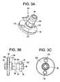
- the adaptor 24 of the arbor assembly 10is best shown in FIGURES 3a-3c .
- the adaptor 24is preferably made from metal, such as, steel and generally includes a shaft 90, a flange 92 and a nose 94.
- the shaft 90is generally cylindrically-shaped.
- the flange 92is generally disc-shaped.
- the diameter of the flange 92is larger than the diameter of the shaft 90.
- the nose 94is also generally cylindrically-shaped.
- the diameter of the nose 94is smaller than the diameter of the flange 92.
- a cylindrically-shaped adaptor passageway 96extends through the adaptor 24.
- the shaft 90 of the adaptor 24has an outer wall 97 which includes a first portion 98, a second portion 100, and a third portion 102.
- the first portion 98is located at the proximal end of the shaft 90 and is generally cylindrically-shaped.
- the first portion 98extends distally from the proximal end to the second portion 100.
- a concave groove 104is provided within the first portion 98 of the outer wall 97 to receive the steel balls 28 as will be described herein.
- the second portion 100extends from the first portion 98 to the third portion 102.
- the second portion 100is hexagonally-shaped.
- the third portion 102extends from the second portion 100 to the flange 92.
- the third portion 102 of the outer wall 97is generally cylindrically-shaped.
- An adaptor shoulder 103is provided where the second portion 100 and the third portion 102 of the outer wall 97 meet.
- the flange 92includes a proximal wall 106 and a distal wall 108.
- Two diametrically opposed mounting apertures 110are provided through the flange 92 of the adaptor 24 and extend from the distal wall 108 to the proximal wall 106 of the flange 92.
- the nose 94 of the adaptor 24is generally cylindrically-shaped.
- the nose 94extends distally from the flange 92 and forms the distal end of the adaptor 24.
- the sleeve 22 of the arbor assembly 10is best shown in FIGURES 4a-4b .
- the sleeve 22is generally tubularly-shaped and is preferably made from metal, such as, steel.
- the sleeve 22includes an exterior surface 116 and an interior surface 118.
- a sleeve passageway 119extends through the axial center of the sleeve 22 from the proximal end of the sleeve 22 to the distal end of the sleeve 22 and is defined by the interior surface 118.
- a cylindrically-shaped ball protrusion 120extends inwardly from the interior surface 118 around the interior circumference of the sleeve 22.
- the ball protrusion 120is provided at approximately the midpoint of the sleeve 22.
- the ball protrusion 120includes a proximal wall 122, a distal wall 124 and an interior wall 126.
- a generally cylindrically-shaped locking protrusion 128also extends inwardly from the interior surface 118 around the interior circumference of the of the sleeve 22.
- the locking protrusion 128is proximate to the distal end of the sleeve 22.
- the locking protrusion 128includes a proximal wall 130 and a convexly curved interior wall 132.
- a flat portion 132aextends distally from the curved interior wall 132 and a flat portion 132b extends distally from the curved interior wall 132.
- An end wall 134is provided proximate the proximal end of the sleeve 22 and extends around the interior circumference of the sleeve 22.
- a set screw recess 136is provided between the end wall 134 and the proximal wall 122 of the ball protrusion 120.
- the set screw recess 136extends around the interior circumference of the sleeve 22.
- the set screw recess 120extends along the length of the sleeve for a distance greater than the diameter of the set screw passageway 78 of the shank 20.
- a ball recess 138is provided between the distal wall 124 of the ball protrusion 120 and the proximal wall 130 of the locking protrusion 128.
- the ball recess 138extends along the length of the sleeve for a distance slightly greater than the diameter of the balls 28.
- An access passageway 140extends from the exterior wall 116 to the interior wall 118.
- the access passageway 140provides access to the set screw 26 as will be described herein.
- the access passageway 140is generally positioned toward the distal end of the set screw recess 136.
- Assembly of the arbor assembly 10begins by placing the C-ring 30 in the C-ring recess 56 of the shank 20.
- the O-ring 32is placed in the O-ring recess 77.
- the pilot drill bit 36is inserted into the shank 20 and the steel balls 28 are placed in the ball passageways 58 of the shank 20.
- the distal end of the sleeve 22is passed over the gripping portion 38 of the shank 20 and then over the intermediate portion 40 of the shank 20 until the distal end of the sleeve 22 passes over the C-ring 30.
- the interior wall 132contacts the steel balls 128 and forces the steel balls 128 within the ball passageways 58 of the shank 20.
- the ball recess 138 of the sleeve 22is generally aligned with the ball passageways 58 of the shank 20, as shown in FIGURE 1 , and the steel balls 28 are free to move into the ball recess 138 of the sleeve 22.
- the set screw 26is passed through the access passageway 140 of the sleeve 22 and into the set screw passageway 78 of the shank 20 until it engages the pilot drill bit 36.
- the sleeve 22can move proximally and distally along the shank 20 for a limited distance. Proximal movement of the sleeve 22 is limited by the contact between the set screw 26 and the proximal wall 122 of the ball protrusion 120 of the sleeve 22. Distal movement of the sleeve 22 is limited by the contact between the set screw 26 and the end wall 134 of the sleeve 22. In this manner, the set screw 26 prohibits the sleeve 22 from sliding off of the shank 20.
- the hole saw 34 to be used in connection with the arbor assemblyincludes a circular back plate 142 and a cylindrically shaped skirt 144 which depends from the back plate 142.
- An aperture 146is provided through the back plate 142 of the hole saw 34 at its axial center.
- Two diametrically opposed mounting apertures 148are also provided through the back plate 142 of the hole saw 34 and are spaced from the aperture 146.
- the hole saw 34is attached to the adaptor 24 of the arbor assembly 10 by passing the nose 94 of the adaptor 24 through the aperture 146 in the backplate 142 of the hole saw 34.
- mounting screws 150are passed through the mounting apertures 148 of the hole saw and then through the mounting passageways 110 of the adaptor 24. The mounting screws 150 are then used to secure the hole saw 34 to the adaptor 24.
- the adaptor 24is then mounted to the remainder of the arbor assembly 10. 5
- the pilot drill bit 36is passed through the adaptor passageway 96 until the proximal wall of the flange 92 of the adaptor 24 is proximate the distal wall of the flange portion 42 of the shank 20.
- the second portion 100 of the shaft 90 of the adaptor 24will rest within the second section 72 of the adaptor portion 68 of the shank passageway 64.
- the hexagonally shaped portion 100 of the shaft 90will rest within the hexagonally shaped portion 72 of the shank passageway 64.
- the shaft 90 and the shank passageway 64can be any one of a variety of shapes which allows the adaptor 24 to be positioned within the shank passageway 64 yet prevents rotation of the adaptor 24 relative to the shank 20.
- the adaptor 24is then locked with the shank 20 and sleeve 22 by sliding the sleeve 22 in the distal direction relative to the shank 20.
- the locking protrusion 128 of the sleeve 22forces the C-ring 30 to compress into the C-ring recess 56 of the shank 20.
- the ball protrusion 120 of the sleeve 22forces the steel balls 28 into the ball passageways 58 of the shank 20.
- the usercontinues to slide the sleeve 22 forward until the locked position of the sleeve 22 is reached.
- the locking protrusion 128 of the sleeve 22is positioned distally of the C-ring 30 and the C-ring 30 expands so that it contacts the flat portion 132a of the inner wall 118 of the sleeve 22 distally of the ball recess 138.
- the ball protrusion 120 of the sleeve 22is positioned radially outwardly of the ball passageways 58 of the shank 20. The ball protrusion 120 forces the balls 28 into the passageways 58 so that the balls 28 contact the concave groove 104 of the adaptor 24.
- the arbor assembly 10is shown in FIGURE 5 in its locked position.
- the pilot drill bit 36is also rotated due to the retention of the pilot drill bit 36 within the pilot portion 66 of the shank passageway 64 by the set screw 26.
- the hexagonally-shaped second section 72 of the adaptor portion 68 of the shank passageway 64transfers rotational force from the drill to the hexagonally-shaped second portion 100 of the adaptor shaft 90, and in turn to the hole saw 34.
- the O-ring 32reduces vibrations as the hole saw 34 is rotated and advanced within the workpiece. As the hole saw 34 cuts the hole in the workpiece, a slug is formed and is generally retained within the skirt 144 of the hole saw.
- the userremoves the adaptor 24 with the attached hole saw 34 in the following manner.
- the userslides the sleeve 22 in the proximal direction relative to the shank 20.
- the locking protrusion 128causes the C-ring 30 to compress.
- the ball protrusion 120 of the sleeve 22moves proximally of the ball passageways 58 of the shank 20 and the ball recess 138 of the sleeve 22 is aligned with the ball passageways 58.
- the sleeve 22is in the unlocked position and the balls 28 can move into the ball recess 138 of the sleeve 22.
- the adaptor 24can be removed from the shank 20 simply by pulling the adaptor 24 in the distal direction.
- the pilot drill 36is stripped from the slug allowing the slug to be easily removed from the skirt 144 of the hole saw 34.
- a new hole saw mounted to another adaptor 24can then be mounted within the shank 20 in the manner described above.
- the hole saw 34can be removed from the adaptor 24 and the new hole saw can be mounted to the adaptor 24 and then mounted within the shank 20.
- the pilot drill bit 36is left in place while the hole saw 34 and the adaptor 24 are dismounted from the remainder of the arbor assembly 10.
- the usercan remove the hole saw 34 to drill the pilot hole in the work piece, allowing the user greater visibility of the workpiece.
- the pilot holecan be more accurately located.
- the adaptor 24 and hole saw 34can be mounted within the shank 20 and sleeve 22.
- the pilot drill bit 36can then be passed through the pilot hole to align the hole saw 34 with the workpiece and the hole saw 34 can be placed close to the workpiece prior to activating the electric drill.
- the improved control over the hole saw 34also reduces the possibility of bending the pilot drill bit 36 which sometimes occurs when a conventional hole saw "crashes into” the workpiece.
- the hole saw 34can be easily removed from the adaptor 24. This allows the hole saw 34 to be replaced when it becomes dull and worn without also replacing the adaptor 24.
- the arbor assembly 200includes a shank 20, a sleeve 22, and an adaptor 224.
- the shank 20 and sleeve 22are identical to the shank 20 and sleeve 22 of the first embodiment 10 of the arbor assembly 10 and therefore the specifics of same are not repeated herein.
- the adaptor 224 of the second embodimentis designed for use with smaller diameter hole saws.
- the adaptor 224is best shown in FIGURES 7a-7d .
- the adaptor 224is generally cylindrically shaped and is preferably made from metal, such as, steel.
- the adaptor 224includes a shaft 226 and a nose 228.
- the shaft 226extends from the proximal end of the adaptor 224 to the nose 228.
- the nose 228 of the adaptor 224extends from the shaft 226 to the distal end of the adaptor 224.
- the adaptor 224includes an inner wall 230 and an outer wall 232.
- a cylindrically shaped adaptor passageway 234is defined by the inner wall 230 and extends from the proximal end to the distal end of the adaptor 224.
- the outer wall 232 of the adaptor 224includes a first portion 236, a second portion 238, and a third portion 240.
- the first portion 236 of the outer wall 232is generally cylindrically-shaped.
- the second portion 238 of the outer wall 232is generally hexagonally-shaped.
- the diameter of the second portion 238is larger than the diameter of the first portion236.
- the third portion 240 of the outer wall 232is generally cylindrically-shaped.
- the diameter of the third portion 240is larger than the diameter of the second portion 238.
- the first portion 236extends from the proximal end of the shaft 226 to the second portion 238; the second portion 238 extends distally from the first portion 236 to the third portion 240; and the third portion 240 extends distally from the second portion 238 to the nose 228.
- a concave groove 242is spaced from the proximal end of the adaptor 224 and is provided within the first portion 236 of the outer wall 232 to receive the steel balls 28.
- a tapered adaptor shoulder 244is provided where the second portion 238 and the third portion 240 of the outer wall 232 meet.
- the nose 228 of the adaptor 224extends distally from the shaft 226.
- a thread 246is provided on the outer wall of the nose 228 of the adaptor 224 for attachment of a hole saw as will be described herein.
- Assembly of the arbor assembly 200begins with assembly of the shank 20, sleeve 22, pilot drill bit 36, and set screw 26 as described with respect to the first embodiment.
- the hole saw(not shown) is then mounted to the adaptor 224.
- the hole sawincludes a circular shaped back plate with a skirt depending therefrom.
- An apertureis provided through the axial center in the back plate of the hole saw.
- a threadis provided on the wall of the aperture in the back plate of the hole saw which is engaged with the thread on the nose 228 of the adaptor 224.
- the adaptor 224is then mounted within the shank 20 and sleeve 22 by aligning the pilot drill bit 36 with the adaptor passageway 234.
- the adaptor 224is moved proximally along the pilot drill bit 36 and within the adaptor passageway 234 until the adaptor shoulder 244 compresses the O-ring 32 within the shank shoulder 74.
- the adaptor 224is then locked with the shank 20 and sleeve 22 by sliding the sleeve 22 in the distal direction relative to the shank 20.
- the shank 20 and the sleeve 22interact in the same manner as described above with respect to the first embodiment to force the balls 28 within the passageways 58 of the shank 20.
- the balls 28As the balls 28 are forced within the ball passageways 58, the balls 28 contact the concave groove 242 of the adaptor 224.
- the adaptor 224is fixed axially within the shank 20.
- the arbor assembly 200is shown in FIGURE 8 in its locked position.
- the arbor assembly 200is used in the same manner as the arbor assembly 10.
- the hexagonally-shaped second section 72 of the adaptor portion 68 of the shank passageway 64provides rotational force to the hexagonally shaped second portion 238 of the adaptor shaft 226, and in turn to the hole saw (not shown).
- the second section 72 of the adaptor portion 68 of the shank passageway 64 and the second portion 238 of the adaptor shaft 226have been described as hexagonally-shaped, it is to be understood that the second section 72 and the second portion 238 could be of a variety of shapes so long as the second portion 238 of the adaptor shaft 226 fits within the second section 72 of the adaptor portion 68 of the shank passageway 64 and rotation of the adaptor 224 relative to the shank 20 is prevented.
- the userremoves the adaptor 224 with the attached hole saw.
- the userslides the sleeve 22 in the proximal direction relative to the shank 20.
- the locking protrusion 128causes the C-ring 30 to compress.
- the ball protrusion 120 of the sleeve 22moves proximally of the ball passageways 58 of the shank 20 and the ball recess 138 of the sleeve 22 are aligned with the ball passageways 58.
- the sleeve 22is in the unlocked position and the balls 28 can move into the ball recesses 138 of the sleeve 22.
- the adaptor 224can be removed from the shank 20 simply by pulling the adaptor 224 in the distal direction.
- the pilot drill 36is stripped from the slug allowing the slug to be easily removed from the skirt 144 of the hole saw 34.
- a new hole saw mounted to another adaptor 224can then be mounted within the shank 20 in the manner described above.
- the hole sawcan be removed from the adaptor 224 and the new hole saw can be mounted to the adaptor 224 and then mounted within the shank 20.
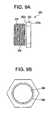
- a bushing 250is shown in FIGURES 9a and 9b .
- the bushing 250is used with the second embodiment of the arbor assembly 200.
- the bushing 250is preferably made from metal, such as, steel and is used to provide additional support to hole saws with larger diameters but which are not so large as to include mounting screws.
- the bushing 250includes a hexagonally shaped flange 252 and a threaded nose 254.
- the flange 252includes a proximal surface 252a and a distal surface 252b.
- the diameter of the nose 254is smaller than the diameter of the flange 252.
- a cylindrically shaped bushing passageway 256extends through the bushing 250 from its proximal end to its distal end.
- An outer thread 258is provided on the outer surface of the nose 254 and an inner thread 260 is provided along the wall of the bushing passageway 256.
- the bushing 250is mounted to the adaptor 224 by passing the nose 228 of the adaptor 224 through the flange 252 of the bushing 250 and then engaging the thread 246 on the adaptor 224 with the inner thread 260 of the bushing 250. Mounting of the bushing 250 to the adaptor 224 is complete when the proximal surface 252a of the flange 252 contacts the distal end of the shaft 226 of the adaptor 224.
- the hole sawis then mounted to the adaptor 224 and bushing 250 by passing the nose 254 of the bushing and the nose 228 of the adaptor 224 through the aperture in the back plate of the hole saw and threadedly engaging the aperture in the hole saw with the outer thread 258 of the bushing 250.
- the adaptor 224is then mounted within the shank 20 and the sleeve 22 and can be dismounted from the shank 20 and the sleeve 22 as described above with respect to the second embodiment of the arbor assembly 200.
Landscapes
- Engineering & Computer Science (AREA)
- Mechanical Engineering (AREA)
- General Engineering & Computer Science (AREA)
- Structural Engineering (AREA)
- Civil Engineering (AREA)
- Environmental & Geological Engineering (AREA)
- Life Sciences & Earth Sciences (AREA)
- Ocean & Marine Engineering (AREA)
- General Life Sciences & Earth Sciences (AREA)
- Mining & Mineral Resources (AREA)
- Paleontology (AREA)
- Environmental Sciences (AREA)
- Drilling Tools (AREA)
- Earth Drilling (AREA)
Abstract
Description
- This invention relates to an arbor assembly which allows a hole saw to be quickly mounted and dismounted from an electric drill. Hole saws are commonly used in connection with electric drills to create holes in work pieces. It is often necessary to create holes of varying sizes and therefore is convenient to be able to quickly mount and dismount hole saws of different sizes to and from an electric drill.
- In
EP 1193014 is disclosed an arbor assembly for mounting a hole saw to a drill, the arbor assembly comprising a shank for engagement with the drill, an adaptor for supporting the hole saw, the adaptor being mounted to the shank, and means for locking the adaptor in engagement with the shank and for unlocking the adaptor from engagement with the shank, the means for locking including a sleeve. - A general object of the present invention is to provide an arbor assembly which allows for easy mounting of a hole saw to an electric drill and dismounting of the hole saw from an electric drill.
- Another object of the present invention is to provide an arbor assembly which allows the hole saw to be mounted and dismounted from the arbor assembly without removing the pilot drill bit.
- Yet another object of the present invention is to reduce vibration of the arbor assembly and the hole saw when in use.
- Still another object of the present invention is to allow for easy replacement of the hole saw when the hole saw becomes worn.
- A further object of the present invention is to provide an arbor assembly which allows for easy removal of a slug from the hole saw.
- Yet a further object of the present invention is to allow for greater visibility upon drilling of a pilot hole.
- Still a further object of the present invention is to eliminate the tendency of the hole saw to crash into the workpiece upon drilling of the pilot hole.
- Briefly, and in accordance with the foregoing, the present invention provides an arbor assembly according to claim 1 including a shank, a sleeve and an adaptor. The sleeve of the arbor assembly is mounted over a portion of the shank. The shank is mounted within the chuck of an electric drill to provide rotation to the arbor assembly. A hole saw is mounted to the adaptor of the arbor assembly. The adaptor and hole saw are easily mounted to the remainder of the arbor assembly by inserting a portion of the adaptor within a passageway of the shank. By moving the sleeve distally, steel balls are forced into engagement with the adaptor to lock the adaptor within the remainder of the arbor assembly.
- The organization and manner of the structure and operation of the invention, together with further objects and advantages thereof, may best be understood by reference to the following description, taken in connection with the accompanying drawings, wherein like reference numerals identify like elements in which:
FIGURE 1 is a cross sectional view of a first embodiment of an arbor assembly in an unlocked position with a hole saw and a pilot drill bit mounted to the arbor assembly;FIGURE 2a is a perspective view of a shank of the arbor assembly ofFIGURE 1 ;FIGURE 2b is a top plan view of the shank ofFIGURE 2a ;FIGURE 2c is a cross-sectional view of the shank along line 2c-2c ofFIGURE 2b ;FIGURE 2d is a left elevational view of the shank ofFIGURE 2a ;FIGURE 2e is a right elevational view of the shank ofFIGURE 2a ;FIGURE 3a is a perspective view of an adaptor of the arbor assembly ofFIGURE 1 ;FIGURE 3b is a front elevational view of the adaptor ofFIGURE 3a and steel balls;FIGURE 3c is a right elevational view of the adaptor ofFIGURE 3b ;FIGURE 4a is a perspective view of a sleeve of the arbor assembly ofFIGURE 1 ;FIGURE 4b is a cross sectional view of the sleeve of theFIGURE 4a ;FIGURE 5 is a cross-sectional view of the arbor assembly ofFIGURE 1 in a locked position with a hole saw and pilot drill bit mounted to the arbor assembly;FIGURE 6 is a cross-sectional view of a second embodiment of the arbor assembly in an unlocked position with a pilot drill bit mounted to the arbor assembly;FIGURE 7a is a front elevational view of the adaptor of the arbor assembly ofFIGURE 6 and steel balls;FIGURE 7b is a cross-sectional view of the adaptor ofFIGURE 7a ;FIGURE 7c is a left elevational view of the adaptor ofFIGURE 7a ;FIGURE 7d is a right elevational view of the adaptor ofFIGURE 7a ;FIGURE 8 is a cross-sectional view of the arbor assembly ofFIGURE 6 in the locked position with a pilot drill bit mounted to the arbor assembly;FIGURE 9a is a front elevational view of a bushing for use in connection with the arbor assembly ofFIGURE 6 ; andFIGURE 9b is a right elevational view of the bushing ofFIGURE 9a .- While the invention may be susceptible to embodiment in different forms, there is shown in the drawings, and herein will be described in detail, specific embodiments with the understanding that the present disclosure is to be considered an exemplification of the invention as defined in the claims, and is not intended to limit the invention to that as illustrated and described herein.
- In describing the invention, use of the word "proximal" shall refer to elements, surfaces or positions closest to a user of the present invention and "distal" shall refer to elements, surfaces or positions furthest from a user of the present invention.
- An
arbor assembly arbor assembly - A first embodiment of the
arbor assembly 10 is shown inFIGURES 1-5 and a second embodiment of thearbor assembly 200 is shown inFIGURES 6-8 . Abushing 250 for use with the second embodiment of thearbor assembly 200 is shown inFIGURES 9a-9b . - Attention is invited to the first embodiment of the
arbor assembly 10 shown inFIGURES 1-5 . Thearbor assembly 10 generally includes ashank 20, asleeve 22, anadaptor 24, aset screw 26,steel balls 28, a steel C-ring 30 and an O-ring 32. Thearbor assembly 10 is shown in its unlocked/open position inFIGURE 1 . A hole saw 34 and apilot drill bit 36 are mounted to thearbor assembly 10. - The
shank 20 is best shown inFIGURES 2a-2e . Theshank 20 is preferably made from metal, such as steel. Theshank 20 generally includes anelongated gripping portion 38, anintermediate portion 40 and aflange portion 42. The grippingportion 38 extends from the proximal end of theshank 20 to theintermediate portion 40. Theintermediate portion 40 extends from thegripping portion 38 to theflange portion 42. Thegripping portion 38 of theshank 20 includes gripping surfaces to be received by the chuck (not shown) of an electric drill (not shown) to provide rotation to thearbor assembly 10. Theintermediate portion 40 and theflange portion 42 receives theadaptor 24 as will be described herein. - The diameter of the
intermediate portion 40 is larger than the diameter of the grippingportion 38. Theintermediate portion 40 includes anouter wall 46 which will engage thesleeve 20 and aninner wall 48 which will engage theadaptor 24 as will be described herein. - The
outer wall 46 includes afirst portion 50, asecond portion 52 andthird portion 54. Thefirst portion 50 of theouter wall 46 is generally angled and joins the grippingportion 38 to theintermediate portion 40. Thesecond portion 52 of the outer wall is generally cylindrical. Thethird portion 54 is angled relative to thesecond portion 52 and joins theintermediate portion 40 to theflange 42. Preferably the angle between thesecond portion 52 and thethird portion 54 is approximately 15 degrees. Theouter wall 46 of theintermediate portion 40 includes a C-ring recess 56 which houses the C-ring 30 for engagement with thesleeve 22 as will be described herein. The C-ring recess is spaced from the distal end of theintermediate portion 40. Two diametricallyopposed ball passageways 58 extend from theouter wall 46 to theinner wall 48. The ball passageways 58 are positioned proximally of the C-ring recess 56. - The diameter of the
flange portion 42 is larger than the diameter of theintermediate portion 40. Theflange portion 42 includes aproximal wall 60 and adistal wall 62. Theproximal wall 60 extends outwardly from thethird portion 54 of theouter wall 46 of theintermediate portion 40. Theproximal wall 60 is generally perpendicular to the axial center line of theshank 20. Thedistal wall 62 forms the distal end of theshank 20. Thedistal wall 62 is preferably angled approximately 80° relative to the axial center line of theshank 20 as best illustrated inFIGURE 1 . - A
shank passageway 64 is defined by theinner wall 48 and extends from the distal end of theshank 20, through theflange portion 42 of theshank 20 and into theintermediate portion 40 of theshank 20. Theshank passageway 64 includes apilot portion 66 and anadaptor portion 68. - The
pilot portion 66 of theshank passageway 64 is generally cylindrical and is located within theintermediate portion 40 of theshank 20. Thepilot portion 66 of theshank passageway 64 receives thepilot drill bit 36 as will be described herein. - The
adaptor portion 68 of theshank passageway 64 extends through theflange portion 42 of theshank 20, into theintermediate portion 40 of theshank 20 and to thepilot portion 66 of theshank passageway 64. The diameter of theadaptor portion 68 of theshank passageway 64 is larger than the diameter of thepilot portion 66 of theshank passageway 64. Theadaptor portion 68 of theshank passageway 64 is in fluid communication with the diametrically opposed ball passageways 58. - The
adaptor portion 68 of theshank passageway 64 includes afirst section 70, a second section 72 and athird section 74. Thefirst section 70 is generally cylindrical and extends from thepilot portion 66 of theshank passageway 64 to the second section 72 of theadaptor portion 68 of theshank passageway 64. Thefirst section 70 extends proximally and distally of the ball passageways 58. The second section 72 of theadaptor portion 68 of theshank passageway 64 is hexagonally-shaped and extends from thefirst section 70 to thethird section 74. The second section 72 of theadaptor portion 68 extends proximally and distally of the C-ring recess 56. Thethird section 74 of theadaptor portion 68 of theshank passageway 64 is cylindrically-shaped and extends from the second section 72 to the distal end of theshank 20. The diameter of thethird section 74 of theadaptor portion 68 of theshank passageway 64 is larger than the diameter of the second section 72 of theadaptor portion 68 of theshank passageway 64. Ashank shoulder 76 is provided where the second section 72 andthird section 74 of theadaptor portion 68 of theshank passageway 64 meet. Thethird section 74 also includes an O-ring recess 77 where the second section 72 and thethird section 74 of theadaptor portion 68 of theshank passageway 64 meet. - A
set screw passageway 78 is provided within theintermediate portion 40 of theshank 20. Theset screw passageway 78 is located proximally of the ball passageways 58. Theset screw passageway 78 extends from theouter wall 46 of theshank 20 to thepilot portion 66 of theshank passageway 64. Theset screw passageway 78 is generally perpendicular to theshank passageway 64. Threads are provided along the wall of theset screw passageway 78 for engaging a set screw 26 (seeFIGURE 1 ) as will be described herein. - The
adaptor 24 of thearbor assembly 10 is best shown inFIGURES 3a-3c . Theadaptor 24 is preferably made from metal, such as, steel and generally includes ashaft 90, aflange 92 and anose 94. Theshaft 90 is generally cylindrically-shaped. Theflange 92 is generally disc-shaped. The diameter of theflange 92 is larger than the diameter of theshaft 90. Thenose 94 is also generally cylindrically-shaped. The diameter of thenose 94 is smaller than the diameter of theflange 92. A cylindrically-shapedadaptor passageway 96 extends through theadaptor 24. - The
shaft 90 of theadaptor 24 has anouter wall 97 which includes afirst portion 98, asecond portion 100, and athird portion 102. Thefirst portion 98 is located at the proximal end of theshaft 90 and is generally cylindrically-shaped. Thefirst portion 98 extends distally from the proximal end to thesecond portion 100. Aconcave groove 104 is provided within thefirst portion 98 of theouter wall 97 to receive thesteel balls 28 as will be described herein. Thesecond portion 100 extends from thefirst portion 98 to thethird portion 102. Thesecond portion 100 is hexagonally-shaped. Thethird portion 102 extends from thesecond portion 100 to theflange 92. Thethird portion 102 of theouter wall 97 is generally cylindrically-shaped. Anadaptor shoulder 103 is provided where thesecond portion 100 and thethird portion 102 of theouter wall 97 meet. - The
flange 92 includes aproximal wall 106 and adistal wall 108. Two diametrically opposed mountingapertures 110 are provided through theflange 92 of theadaptor 24 and extend from thedistal wall 108 to theproximal wall 106 of theflange 92. - The
nose 94 of theadaptor 24 is generally cylindrically-shaped. Thenose 94 extends distally from theflange 92 and forms the distal end of theadaptor 24. - The
sleeve 22 of thearbor assembly 10 is best shown inFIGURES 4a-4b . Thesleeve 22 is generally tubularly-shaped and is preferably made from metal, such as, steel. Thesleeve 22 includes anexterior surface 116 and aninterior surface 118. Asleeve passageway 119 extends through the axial center of thesleeve 22 from the proximal end of thesleeve 22 to the distal end of thesleeve 22 and is defined by theinterior surface 118. - A cylindrically-shaped
ball protrusion 120 extends inwardly from theinterior surface 118 around the interior circumference of thesleeve 22. Theball protrusion 120 is provided at approximately the midpoint of thesleeve 22. Theball protrusion 120 includes aproximal wall 122, adistal wall 124 and aninterior wall 126. - A generally cylindrically-shaped
locking protrusion 128 also extends inwardly from theinterior surface 118 around the interior circumference of the of thesleeve 22. The lockingprotrusion 128 is proximate to the distal end of thesleeve 22. The lockingprotrusion 128 includes aproximal wall 130 and a convexly curvedinterior wall 132. Aflat portion 132a extends distally from the curvedinterior wall 132 and aflat portion 132b extends distally from the curvedinterior wall 132. - An
end wall 134 is provided proximate the proximal end of thesleeve 22 and extends around the interior circumference of thesleeve 22. Aset screw recess 136 is provided between theend wall 134 and theproximal wall 122 of theball protrusion 120. Theset screw recess 136 extends around the interior circumference of thesleeve 22. Theset screw recess 120 extends along the length of the sleeve for a distance greater than the diameter of theset screw passageway 78 of theshank 20. - A
ball recess 138 is provided between thedistal wall 124 of theball protrusion 120 and theproximal wall 130 of the lockingprotrusion 128. Theball recess 138 extends along the length of the sleeve for a distance slightly greater than the diameter of theballs 28. - An
access passageway 140 extends from theexterior wall 116 to theinterior wall 118. Theaccess passageway 140 provides access to theset screw 26 as will be described herein. Theaccess passageway 140 is generally positioned toward the distal end of theset screw recess 136. - Assembly of the
arbor assembly 10 begins by placing the C-ring 30 in the C-ring recess 56 of theshank 20. The O-ring 32 is placed in the O-ring recess 77. Thepilot drill bit 36 is inserted into theshank 20 and thesteel balls 28 are placed in the ball passageways 58 of theshank 20. Next, the distal end of thesleeve 22 is passed over the grippingportion 38 of theshank 20 and then over theintermediate portion 40 of theshank 20 until the distal end of thesleeve 22 passes over the C-ring 30. As the distal end of thesleeve 22 is passed over theshank 20, theinterior wall 132 contacts thesteel balls 128 and forces thesteel balls 128 within the ball passageways 58 of theshank 20. When the distal end of thesleeve 22 has passed over the C-ring 30 theball recess 138 of thesleeve 22 is generally aligned with the ball passageways 58 of theshank 20, as shown inFIGURE 1 , and thesteel balls 28 are free to move into theball recess 138 of thesleeve 22. - Next, the
set screw 26 is passed through theaccess passageway 140 of thesleeve 22 and into theset screw passageway 78 of theshank 20 until it engages thepilot drill bit 36. Theset screw 26, when mounted in the setscrew passage way 78, provides a "stop" for thesleeve 22. Thesleeve 22 can move proximally and distally along theshank 20 for a limited distance. Proximal movement of thesleeve 22 is limited by the contact between theset screw 26 and theproximal wall 122 of theball protrusion 120 of thesleeve 22. Distal movement of thesleeve 22 is limited by the contact between theset screw 26 and theend wall 134 of thesleeve 22. In this manner, theset screw 26 prohibits thesleeve 22 from sliding off of theshank 20. - As shown in
FIGURE 5 , the hole saw 34 to be used in connection with the arbor assembly includes acircular back plate 142 and a cylindrically shapedskirt 144 which depends from theback plate 142. Anaperture 146 is provided through theback plate 142 of thehole saw 34 at its axial center. Two diametrically opposed mountingapertures 148 are also provided through theback plate 142 of thehole saw 34 and are spaced from theaperture 146. - The
hole saw 34 is attached to theadaptor 24 of thearbor assembly 10 by passing thenose 94 of theadaptor 24 through theaperture 146 in thebackplate 142 of thehole saw 34. Next, mountingscrews 150 are passed through the mountingapertures 148 of the hole saw and then through the mountingpassageways 110 of theadaptor 24. The mountingscrews 150 are then used to secure the hole saw 34 to theadaptor 24. - The
adaptor 24 is then mounted to the remainder of thearbor assembly 10. 5 Thepilot drill bit 36 is passed through theadaptor passageway 96 until the proximal wall of theflange 92 of theadaptor 24 is proximate the distal wall of theflange portion 42 of theshank 20. When theadaptor 24 is mounted within theshank 20, thesecond portion 100 of theshaft 90 of theadaptor 24 will rest within the second section 72 of theadaptor portion 68 of theshank passageway 64. Thus, the hexagonally shapedportion 100 of theshaft 90 will rest within the hexagonally shaped portion 72 of theshank passageway 64. When theadaptor 24 is properly aligned within theshank 20, the O-ring 32 is compressed between theshank shoulder 76 and theadaptor shoulder 103. Although the second portion 72 of theshank passageway 64 of theshank 20 and theportion 100 of theshaft 90 of theadaptor 24 are described as hexagonally-shaped, it is to be understood that theshaft 90 and theshank passageway 64 can be any one of a variety of shapes which allows theadaptor 24 to be positioned within theshank passageway 64 yet prevents rotation of theadaptor 24 relative to theshank 20. - The
adaptor 24 is then locked with theshank 20 andsleeve 22 by sliding thesleeve 22 in the distal direction relative to theshank 20. As thesleeve 22 slides in the distal direction, the lockingprotrusion 128 of thesleeve 22 forces the C-ring 30 to compress into the C-ring recess 56 of theshank 20. At the same time, theball protrusion 120 of thesleeve 22 forces thesteel balls 28 into the ball passageways 58 of theshank 20. The user continues to slide thesleeve 22 forward until the locked position of thesleeve 22 is reached. When thesleeve 22 is in the locked position, the lockingprotrusion 128 of thesleeve 22 is positioned distally of the C-ring 30 and the C-ring 30 expands so that it contacts theflat portion 132a of theinner wall 118 of thesleeve 22 distally of theball recess 138. Also, when thesleeve 22 is in the locked position, theball protrusion 120 of thesleeve 22 is positioned radially outwardly of the ball passageways 58 of theshank 20. Theball protrusion 120 forces theballs 28 into thepassageways 58 so that theballs 28 contact theconcave groove 104 of theadaptor 24. As a result of the contact between theballs 28 and theadaptor 24, theadaptor 24 is fixed axially within theshank 20. Thearbor assembly 10 is shown inFIGURE 5 in its locked position. - In use, as the
shank 20 is rotated by the drill, thepilot drill bit 36 is also rotated due to the retention of thepilot drill bit 36 within thepilot portion 66 of theshank passageway 64 by theset screw 26. The hexagonally-shaped second section 72 of theadaptor portion 68 of theshank passageway 64 transfers rotational force from the drill to the hexagonally-shapedsecond portion 100 of theadaptor shaft 90, and in turn to thehole saw 34. The O-ring 32 reduces vibrations as thehole saw 34 is rotated and advanced within the workpiece. As thehole saw 34 cuts the hole in the workpiece, a slug is formed and is generally retained within theskirt 144 of the hole saw. - If the user desires to use a different hole saw, perhaps one with a skirt with a different diameter, the user removes the
adaptor 24 with the attachedhole saw 34 in the following manner. The user slides thesleeve 22 in the proximal direction relative to theshank 20. As thesleeve 22 is pulled in the proximal direction, the lockingprotrusion 128 causes the C-ring 30 to compress. As the user continues to pull thesleeve 22 in the proximal direction, theball protrusion 120 of thesleeve 22 moves proximally of the ball passageways 58 of theshank 20 and theball recess 138 of thesleeve 22 is aligned with the ball passageways 58. At this point thesleeve 22 is in the unlocked position and theballs 28 can move into theball recess 138 of thesleeve 22. As theballs 28 are no longer in engagement with theadaptor 24, theadaptor 24 can be removed from theshank 20 simply by pulling theadaptor 24 in the distal direction. As theadaptor 24 is pulled distally, thepilot drill 36 is stripped from the slug allowing the slug to be easily removed from theskirt 144 of thehole saw 34. A new hole saw mounted to anotheradaptor 24 can then be mounted within theshank 20 in the manner described above. Alternatively, thehole saw 34 can be removed from theadaptor 24 and the new hole saw can be mounted to theadaptor 24 and then mounted within theshank 20. - As can be seen from the above description, the
pilot drill bit 36 is left in place while thehole saw 34 and theadaptor 24 are dismounted from the remainder of thearbor assembly 10. The user can remove the hole saw 34 to drill the pilot hole in the work piece, allowing the user greater visibility of the workpiece. Thus, the pilot hole can be more accurately located. In addition, by drilling the pilot hole without thehole saw 34 attached, the pilot hole can be drilled without concern of thehole saw 34 "crashing into" the workpiece. Once the pilot hole is drilled, theadaptor 24 andhole saw 34 can be mounted within theshank 20 andsleeve 22. Thepilot drill bit 36 can then be passed through the pilot hole to align thehole saw 34 with the workpiece and thehole saw 34 can be placed close to the workpiece prior to activating the electric drill. Thus, the user has greater control over thehole saw 34 as it approaches the workpiece. The improved control over thehole saw 34 also reduces the possibility of bending thepilot drill bit 36 which sometimes occurs when a conventional hole saw "crashes into" the workpiece. - As also can be seen from the above description, the
hole saw 34 can be easily removed from theadaptor 24. This allows the hole saw 34 to be replaced when it becomes dull and worn without also replacing theadaptor 24. - Attention is now invited to the second embodiment of the arbor assembly shown in
FIGURES 6-8 . Thearbor assembly 200 includes ashank 20, asleeve 22, and anadaptor 224. Theshank 20 andsleeve 22 are identical to theshank 20 andsleeve 22 of thefirst embodiment 10 of thearbor assembly 10 and therefore the specifics of same are not repeated herein. Theadaptor 224 of the second embodiment is designed for use with smaller diameter hole saws. - The
adaptor 224 is best shown inFIGURES 7a-7d . Theadaptor 224 is generally cylindrically shaped and is preferably made from metal, such as, steel. Theadaptor 224 includes ashaft 226 and anose 228. Theshaft 226 extends from the proximal end of theadaptor 224 to thenose 228. Thenose 228 of theadaptor 224 extends from theshaft 226 to the distal end of theadaptor 224. Theadaptor 224 includes aninner wall 230 and anouter wall 232. A cylindrically shapedadaptor passageway 234 is defined by theinner wall 230 and extends from the proximal end to the distal end of theadaptor 224. - The
outer wall 232 of theadaptor 224 includes afirst portion 236, asecond portion 238, and athird portion 240. Thefirst portion 236 of theouter wall 232 is generally cylindrically-shaped. Thesecond portion 238 of theouter wall 232 is generally hexagonally-shaped. The diameter of thesecond portion 238 is larger than the diameter of the first portion236. Thethird portion 240 of theouter wall 232 is generally cylindrically-shaped. The diameter of thethird portion 240 is larger than the diameter of thesecond portion 238. Thefirst portion 236 extends from the proximal end of theshaft 226 to thesecond portion 238; thesecond portion 238 extends distally from thefirst portion 236 to thethird portion 240; and thethird portion 240 extends distally from thesecond portion 238 to thenose 228. Aconcave groove 242 is spaced from the proximal end of theadaptor 224 and is provided within thefirst portion 236 of theouter wall 232 to receive thesteel balls 28. A taperedadaptor shoulder 244 is provided where thesecond portion 238 and thethird portion 240 of theouter wall 232 meet. - The
nose 228 of theadaptor 224 extends distally from theshaft 226. Athread 246 is provided on the outer wall of thenose 228 of theadaptor 224 for attachment of a hole saw as will be described herein. - Assembly of the
arbor assembly 200 begins with assembly of theshank 20,sleeve 22,pilot drill bit 36, and setscrew 26 as described with respect to the first embodiment. - The hole saw (not shown) is then mounted to the
adaptor 224. The hole saw includes a circular shaped back plate with a skirt depending therefrom. An aperture is provided through the axial center in the back plate of the hole saw. A thread is provided on the wall of the aperture in the back plate of the hole saw which is engaged with the thread on thenose 228 of theadaptor 224. - The
adaptor 224 is then mounted within theshank 20 andsleeve 22 by aligning thepilot drill bit 36 with theadaptor passageway 234. Theadaptor 224 is moved proximally along thepilot drill bit 36 and within theadaptor passageway 234 until theadaptor shoulder 244 compresses the O-ring 32 within theshank shoulder 74. - The
adaptor 224 is then locked with theshank 20 andsleeve 22 by sliding thesleeve 22 in the distal direction relative to theshank 20. Theshank 20 and thesleeve 22 interact in the same manner as described above with respect to the first embodiment to force theballs 28 within thepassageways 58 of theshank 20. As theballs 28 are forced within the ball passageways 58, theballs 28 contact theconcave groove 242 of theadaptor 224. As a result of the contact between theballs 28 and theadaptor 224, theadaptor 224 is fixed axially within theshank 20. Thearbor assembly 200 is shown inFIGURE 8 in its locked position. - The
arbor assembly 200 is used in the same manner as thearbor assembly 10. The hexagonally-shaped second section 72 of theadaptor portion 68 of theshank passageway 64 provides rotational force to the hexagonally shapedsecond portion 238 of theadaptor shaft 226, and in turn to the hole saw (not shown). Although the second section 72 of theadaptor portion 68 of theshank passageway 64 and thesecond portion 238 of theadaptor shaft 226 have been described as hexagonally-shaped, it is to be understood that the second section 72 and thesecond portion 238 could be of a variety of shapes so long as thesecond portion 238 of theadaptor shaft 226 fits within the second section 72 of theadaptor portion 68 of theshank passageway 64 and rotation of theadaptor 224 relative to theshank 20 is prevented. - If the user desires to use a different hole saw, perhaps one with a skirt with a different diameter, the user removes the
adaptor 224 with the attached hole saw. The user slides thesleeve 22 in the proximal direction relative to theshank 20. As thesleeve 22 is pulled in the proximal direction, the lockingprotrusion 128 causes the C-ring 30 to compress. As the user continues to pull thesleeve 22 in the proximal direction theball protrusion 120 of thesleeve 22 moves proximally of the ball passageways 58 of theshank 20 and theball recess 138 of thesleeve 22 are aligned with the ball passageways 58. At this point thesleeve 22 is in the unlocked position and theballs 28 can move into the ball recesses 138 of thesleeve 22. As theballs 28 are no longer in engagement with theadaptor 224, theadaptor 224 can be removed from theshank 20 simply by pulling theadaptor 224 in the distal direction. As theadaptor 224 is pulled distally, thepilot drill 36 is stripped from the slug allowing the slug to be easily removed from theskirt 144 of thehole saw 34. A new hole saw mounted to anotheradaptor 224 can then be mounted within theshank 20 in the manner described above. Alternatively, the hole saw can be removed from theadaptor 224 and the new hole saw can be mounted to theadaptor 224 and then mounted within theshank 20. - A
bushing 250 is shown inFIGURES 9a and 9b . Thebushing 250 is used with the second embodiment of thearbor assembly 200. Thebushing 250 is preferably made from metal, such as, steel and is used to provide additional support to hole saws with larger diameters but which are not so large as to include mounting screws. - The
bushing 250 includes a hexagonally shapedflange 252 and a threadednose 254. Theflange 252 includes aproximal surface 252a and adistal surface 252b. The diameter of thenose 254 is smaller than the diameter of theflange 252. A cylindrically shapedbushing passageway 256 extends through thebushing 250 from its proximal end to its distal end. Anouter thread 258 is provided on the outer surface of thenose 254 and aninner thread 260 is provided along the wall of thebushing passageway 256. - The
bushing 250 is mounted to theadaptor 224 by passing thenose 228 of theadaptor 224 through theflange 252 of thebushing 250 and then engaging thethread 246 on theadaptor 224 with theinner thread 260 of thebushing 250. Mounting of thebushing 250 to theadaptor 224 is complete when theproximal surface 252a of theflange 252 contacts the distal end of theshaft 226 of theadaptor 224. - The hole saw is then mounted to the
adaptor 224 andbushing 250 by passing thenose 254 of the bushing and thenose 228 of theadaptor 224 through the aperture in the back plate of the hole saw and threadedly engaging the aperture in the hole saw with theouter thread 258 of thebushing 250. - The
adaptor 224 is then mounted within theshank 20 and thesleeve 22 and can be dismounted from theshank 20 and thesleeve 22 as described above with respect to the second embodiment of thearbor assembly 200. - While preferred embodiments of the present invention are shown and described, it is envisioned that those skilled in the art may devise various modifications of the present invention without departing from the scope of the attached claims.
Claims (25)
- An arbour assembly (10) for mounting a hole saw (34) to a drill, the arbor assembly (10) comprising:a shank (20) for engagement with the drill;an adaptor (24) for supporting the hole saw (34), said adaptor (24) being mounted to said shank (20); andmeans (22, 28) for locking said adaptor (24) in engagement with said shank (20) and for unlocking said adaptor (24) from engagement with said shank (20), said means (22, 28) for locking including a sleeve (22);characterised in that said shank (20) includes a set screw passageway (78) and a set screw (26) is positioned within said set screw passageway (78); and said means for locking includes a set screw recess (136) in said sleeve (22), said sleeve being maintained on said shank (20) due to engagement between said set screw (26) and said set screw recess (136).
- An arbour assembly as defined in claim 1,characterised in that said sleeve (22) includes a set screw access passageway (140) for providing access to said set screw (26).
- An arbour assembly as defined in claim 1, further including a pilot drill bit (36) mounted within said shank (20).
- An arbour assembly as defined in claim 1,characterised in that said assembly further includes a pilot drill bit (36) maintained within said shank (20) by said set screw (26).
- An arbour assembly as defined in claim 1,characterised in that said means for locking further includes at least one locking ball passageway (58) through said shank (20) and a locking ball (28), andcharacterised in that movement of said sleeve (22) is limited by said set screw (26) to maintain said locking ball (28) at least partially within said locking ball passageway (58).
- An arbour assembly for mounting a hole saw to a drill as defined in claim 1, furthercharacterised in that
said sleeve (22) further includes a set screw access passageway (140) for providing access to said set screw (26). - An arbour assembly for mounting a hole saw to a drill as defined in claim 1, furthercharacterized in that:said_set screw (26) is mounted to said shank (20);said adaptor (24) is slidably engaged with said shank (20); and said sleeve (22) is slidably engaged with said shank (20).
- An arbour assembly for mounting a hole saw to a drill as defined in claim 1, furthercharacterized in that said shank (20) includes an O-ring recess (77);
an O-ring (32) is positioned within said O-ring recess (77), said O-ring (32) reducing vibrations when the hole saw is rotated by the arbor assembly; and
said adaptor (24) further includes a shoulder (103) for engaging said O-ring (32). - An arbour assembly as defined in claim 8,characterised in that said shank (20) includes a shank passageway (64) and a portion of said adaptor is mounted within said shank passageway (64).
- An arbour assembly as defined in claim 9,characterised in that a portion of said shank passageway (64) includes flats and said adaptor (24) includes flats on an exterior surface,characterised in that said flats on said portion of said shank passageway mate with said flats on said exterior surface of said adaptor (24).
- An arbour assembly as defined in claim 9,characterised in that said means for locking includes at least one ball passageway (58) in said shank and a ball groove (184) in said adaptor (24), andcharacterised in that when said adaptor (24) is positioned within said shank passageway (64), said at least one ball passageway (58) is aligned with said ball groove (104).
- An arbour assembly as defined in claim 11,characterised in that said means for locking further includes at least one locking ball (28) positioned within said at least one ball passageway (58).
- An arbour assembly as defined in claim 12,characterised in that said means for locking further includes a ball protrusion (120) extending from an inner surface of said sleeve (22) for moving said locking ball (28) into engagement with said ball groove (104) of said adaptor (24).
- An arbour assembly as defined in claim 8, further including a C-ring recess (56) on an outer surface of said shank (20); a C-ring (30) positioned therein; and said means for locking includes a locking protrusion extending from an inner surface of said sleeve (22), andcharacterised in that when said locking protrusion (128) is positioned distally of said C-ring (56) to lock said assembly and said locking protrusion (128) is positioned proximally of said C-ring (56) to unlock said assembly.
- An arbour assembly as defined in claim 8,characterised in that said adaptor (224) includes a threaded nose (228) for positioning within an aperture through a backplate of a hole saw.
- An arbour assembly as defined in claim 15, further including a bushing (250) mounted to said nose (228) of said adaptor (224).
- An arbour assembly as defined in claim 8,characterised in that said O-ring (32) is compressed between said shoulder of said adaptor (24) and said shank (20).
- An arbour assembly as defined in claim 8,characterised in that said adaptor (24) includes a shaft (90) having a proximal end and a distal end, a flange (92) extending outwardly from said shaft (90) adjacent said distal end; and at least two apertures (110) through said flange (92) capable of receiving hole saw mounting screws.
- An arbour assembly as defined in claim 8,characterised in that said shank (20) includes a set screw passageway (78) and a set screw (26) positioned within said set screw passageway (78).
- An arbour assembly for mounting a hole saw to a drill as defined in claim 1, furthercharacterized in that
said shank (20) includes an O-ring recess (77);
said adaptor includes a shaft (90) having a proximal end and a distal end, a flange (92) extending outwardly from said shaft (90) adjacent said distal end, and at least two apertures (110) through said flange (92) capable of receiving hole saw mounting screws;
an O-ring (32) is positioned within said O-ring recess (77), said O-ring (32) reducing vibrations when the hole saw is rotated by the arbour assembly; and
said adaptor (24) further includes a nose (94) extending from said distal end of said shaft (90) wherein the diameter of said nose (94) is sized to extend through an aperture through the backplate of the hole saw. - An arbour assembly for mounting a hole saw to a drill as defined in claim 1, furthercharacterized in that:said adaptor (24) is slidably engaged with said shank (20), said adaptor (24) further including a shaft (90) having a proximal end and a distal end and a flange (92) extending outwardly from said shaft (90) adjacent said distal end, and at least two apertures (110) provided through said flange (92) for accepting fasteners extending through a backplate of the hole saw; anda nose (94) extending from said distal end of said shaft (90) wherein the diameter of said nose (94) is sized to extend through an aperture through the backplate of the hole saw.
- An arbour assembly as defined in claim 1, furthercharacterised in that said adaptor (24) is configured for use in connection with a quick change assembly and further includes a shaft (90) having a proximal end and a distal end;
a pilot drill bit passageway (96) through said shaft (90);
a flange (92) extending outwardly from said shaft (90) adjacent said distal end; at least two apertures (110) extending through said flange (92) capable of receiving hole saw mounting screws; and
a nose (94) extending from said distal end of said shaft (90) wherein the diameter of said nose (94) is sized to extend through an aperture through the backplate of the hole saw. - An arbour assembly as defined in claim 1, furthercharacterized in that said adaptor (24) is configured for use in connection with a quick change assembly and further includes
a shaft (90) having a proximal end and a distal end;
a pilot drill bit passageway (96) through said shaft (90);
a flange (92) extending outwardly from said shaft (90) adjacent said distal end; at least two apertures (110) extending through said flange (92) capable of receiving hole saw mounting screws; and
a shoulder (103) extending around a circumference of said shaft (90). - An arbour assembly as defined in claim 23,characterised in that at least a portion (100) of the outer surface of said shaft (90) is hexagonally-shaped.
- An arbour assembly as defined in claim 23, further including a ball groove (104) extending around a circumference of said shaft (90).
Applications Claiming Priority (2)
| Application Number | Priority Date | Filing Date | Title |
|---|---|---|---|
| US44838703P | 2003-02-18 | 2003-02-18 | |
| US448387P | 2003-02-18 |
Publications (3)
| Publication Number | Publication Date |
|---|---|
| EP1449606A2 EP1449606A2 (en) | 2004-08-25 |
| EP1449606A3 EP1449606A3 (en) | 2006-04-05 |
| EP1449606B1true EP1449606B1 (en) | 2010-09-22 |
Family
ID=32736521
Family Applications (1)
| Application Number | Title | Priority Date | Filing Date |
|---|---|---|---|
| EP04075355AExpired - LifetimeEP1449606B1 (en) | 2003-02-18 | 2004-02-06 | Universal quick change hole saw arbor |
Country Status (8)
| Country | Link |
|---|---|
| US (1) | US7112016B2 (en) |
| EP (1) | EP1449606B1 (en) |
| KR (1) | KR20040074943A (en) |
| CN (3) | CN1332776C (en) |
| AT (1) | ATE482045T1 (en) |
| CA (1) | CA2457241C (en) |
| DE (1) | DE602004029213D1 (en) |
| TW (1) | TWI266665B (en) |
Families Citing this family (52)
| Publication number | Priority date | Publication date | Assignee | Title |
|---|---|---|---|---|
| CA2485935C (en) | 2003-10-23 | 2007-12-18 | Darren L. Wendzina | Arbor apparatus for rotary tools |
| ES2332054T3 (en)* | 2004-12-10 | 2010-01-25 | A.V. Custom Style B.V. | FAST MOUNTING TOOL HOLDER TREE WITH PLUG EJECTION, FOR A CROWN SAW. |
| DE102004062912A1 (en)* | 2004-12-22 | 2006-08-17 | C. & E. Fein Gmbh | Drilling tool and drill |
| US20060280569A1 (en)* | 2004-12-23 | 2006-12-14 | Davis John D | Hole Saw Arbor System For Power Drill Assisted Tightening And Loosening |
| WO2007036043A1 (en)* | 2005-09-28 | 2007-04-05 | Maxtech Manufacturing Inc. | Hole saw mandrel |
| TWM294374U (en)* | 2006-01-11 | 2006-07-21 | K & W Tools Co Ltd | Hole cutter knife with quick-release function |
| US7824137B2 (en)* | 2006-05-17 | 2010-11-02 | Maxtech Consumer Products Limited | Universal quick connect system for a hole saw |
| US7802948B1 (en)* | 2006-06-07 | 2010-09-28 | Matthew R Bastiaans | Drill extender |
| US8038371B2 (en)* | 2007-04-13 | 2011-10-18 | Black & Decker Inc. | Push button holesaw mandrel assembly |
| US8038372B2 (en) | 2007-04-13 | 2011-10-18 | Black & Decker Inc. | Push button holesaw mandrel assembly |
| US8434976B2 (en)* | 2009-03-20 | 2013-05-07 | Black & Decker Inc. | Small hole saw mandrel assembly |
| CA2712796A1 (en)* | 2009-08-06 | 2011-02-06 | Textron Innovations Inc. | Hole saw with tapered pilot bit |
| US8721236B2 (en)* | 2009-10-23 | 2014-05-13 | Milwaukee Electric Tool Corporation | Power tool arbor device |
| BR112012026814A2 (en)* | 2010-04-20 | 2016-07-12 | Starrett L S Co | spindle and hollow saw spindle system |
| CN101972157B (en)* | 2010-09-30 | 2011-12-21 | 重庆润泽医疗器械有限公司 | Drill bit locking device and drill bit |
| CN101926671B (en)* | 2010-09-30 | 2011-08-31 | 重庆润泽医疗器械有限公司 | Locking equipment for drill and drill |
| US20120093599A1 (en)* | 2010-10-14 | 2012-04-19 | Thomas Evatt | Cutting tool |
| WO2012154283A1 (en)* | 2011-03-08 | 2012-11-15 | Infusion Brands, Inc. | Dual blade hole saw |
| NL2006364C2 (en)* | 2011-03-10 | 2012-09-11 | Mpe Techniek B V | QUICK-CHANGE SYSTEM FOR ROTATABLE TOOLS, AND FOOT OF SUCH SYSTEM. |
| CH705121A1 (en) | 2011-06-16 | 2012-12-31 | Arx Ag | Quick coupling for connecting a replaceable head. |
| CA2850582A1 (en)* | 2011-06-16 | 2012-12-20 | Von Arx Ag | Quick coupling system for fastening an interchangeable head on a press tool |
| CH705122A1 (en) | 2011-06-16 | 2012-12-31 | Arx Ag | Quick coupling for connecting a replaceable head. |
| PL2800645T3 (en)* | 2012-01-03 | 2016-09-30 | Multi-position hole saw assembly with plug ejector | |
| US9573263B2 (en) | 2012-04-18 | 2017-02-21 | Ridge Tool Company | Work tools having interchangeable work heads |
| WO2014015154A1 (en) | 2012-07-18 | 2014-01-23 | Milwaukee Electric Tool Corporation | Hole saw |
| NL1040196C2 (en)* | 2013-05-03 | 2014-11-04 | Boorwerk B V | QUICK-CHANGE SYSTEM FOR ROTARY TOOLS. |
| DE202013006690U1 (en)* | 2013-07-19 | 2013-08-07 | EasyWork UG (haftungsbeschrängt) | Pick-up for a hole saw and tool arrangement |
| CN103487281B (en)* | 2013-10-16 | 2015-12-02 | 齐鲁工业大学 | Powder machine is got in a kind of concrete chloride ion content test |
| CH709351A1 (en)* | 2014-03-11 | 2015-09-15 | Erowa Ag | Coupling device for a handling device. |
| US9707626B2 (en) | 2014-10-22 | 2017-07-18 | Rote Mate Industry Co., Ltd. | Hole saw assembly |
| NL2013758B1 (en)* | 2014-11-07 | 2016-10-06 | Boorwerk B V | System for releasably coupling a hole saw to a drill shank. |
| CN106476081B (en)* | 2015-08-27 | 2018-11-30 | 广颖机械工业股份有限公司 | Rolling mechanism for transmission shaft of carpentry machine |
| CN106903351B (en)* | 2015-12-22 | 2020-06-05 | 博世电动工具(中国)有限公司 | Adapter for hole saw and electric tool with same |
| SE540445C2 (en)* | 2016-04-29 | 2018-09-18 | Kapman Ab | Holder for a rotary tool, such as a hole saw |
| CN109070244B (en)* | 2016-06-08 | 2020-10-16 | 格利浦-X有限公司 | Hole saw assembly |
| NL2018062B1 (en)* | 2016-12-23 | 2018-07-02 | Toproc A G | Quick change tool |
| US11364558B2 (en)* | 2017-11-03 | 2022-06-21 | Milwaukee Electric Tool Corporation | Hole saw arbor having an adjustable connection mechanism |
| USD851145S1 (en) | 2017-11-20 | 2019-06-11 | John D. Davis | Modular flywheel holesaw |
| US10442011B1 (en)* | 2017-11-20 | 2019-10-15 | Me3, Inc | Modular flywheel holesaw system |
| JP7079475B2 (en)* | 2018-02-14 | 2022-06-02 | 株式会社ミヤナガ | Drilling device for enlarged holes |
| CN216028284U (en) | 2018-07-10 | 2022-03-15 | 米沃奇电动工具公司 | Hole saw |
| US10368880B1 (en) | 2018-10-17 | 2019-08-06 | King Saud University | Universal base attachment bit and cutting bit assembly |
| CN109626293A (en)* | 2019-01-08 | 2019-04-16 | 江苏普华盛包装科技有限公司 | A kind of Cao rotating head of fast demountable |
| USD903454S1 (en)* | 2019-01-24 | 2020-12-01 | William Edwin Kuhns | Hole saw arbor |
| AU2020295404B2 (en) | 2019-06-20 | 2025-05-29 | Milwaukee Electric Tool Corporation | Hole saw with circular sidewall openings |
| USD958855S1 (en) | 2019-12-09 | 2022-07-26 | Milwaukee Electric Tool Corporation | Hole saw |
| KR102460895B1 (en) | 2020-09-11 | 2022-11-01 | 박도준 | Hallsaw socket |
| WO2023004319A1 (en)* | 2021-07-20 | 2023-01-26 | Milwaukee Electric Tool Corporation | Cutting tool |
| US11872642B2 (en) | 2021-11-12 | 2024-01-16 | Robert James Suhling | Dynamicaly configurable arbor assembly apparatus |
| CN114700534A (en)* | 2022-04-28 | 2022-07-05 | 俞安郭 | A hole opener for quick change of handle |
| CN114918461B (en)* | 2022-07-22 | 2022-11-18 | 江苏万众精密工具有限公司 | Multi-aperture integrated drill bit and working method thereof |
| WO2025112037A1 (en)* | 2023-12-01 | 2025-06-05 | 宁波文舰五金有限公司 | Hole spacing quick-change adapter |
Family Cites Families (27)
| Publication number | Priority date | Publication date | Assignee | Title |
|---|---|---|---|---|
| US3138183A (en)* | 1962-09-04 | 1964-06-23 | William S Stewart | Rotary saw control means |
| US3647310A (en)* | 1970-04-03 | 1972-03-07 | Mansfield K Morse | Universal hole saw arbor |
| JPS5153514Y2 (en)* | 1973-12-01 | 1976-12-21 | ||
| US3973862A (en)* | 1975-06-02 | 1976-08-10 | Segal F | Pilot drill locating means for hole saw assembly |
| US4171821A (en)* | 1978-02-16 | 1979-10-23 | Chamberlain Manufacturing Company | Quick change collet tool holder assembly |
| JPS5689414A (en) | 1979-12-15 | 1981-07-20 | Oomi Kogyo Kk | Drilling cutter for reinforced concrete |
| US4551045A (en)* | 1984-03-12 | 1985-11-05 | Joseph Bossler | Countersink core drill assembly and method of utilizing same |
| US4741651A (en)* | 1986-04-25 | 1988-05-03 | Despres Roger J | Hole saw |
| JPS6458409A (en)* | 1987-08-31 | 1989-03-06 | Tobu Cleaner Service | Cutter |
| JPH07100247B2 (en)* | 1989-10-11 | 1995-11-01 | 株式会社ハウスビーエム | Hole saw |
| CN2134902Y (en)* | 1991-12-04 | 1993-06-02 | 翁渊源 | Combined multi-axis boring, drilling, reaming, tapping device |
| US5779404A (en)* | 1994-05-02 | 1998-07-14 | Jore; Matthew B. | Reversible drill/driver tool |
| US5577743A (en)* | 1995-05-10 | 1996-11-26 | Power Tool Holders, Inc. | Quick release chuck device |
| US5624213A (en)* | 1995-05-11 | 1997-04-29 | Evergreen Tool Co., Inc. | Hole producing assembly |
| US5658102A (en)* | 1995-09-12 | 1997-08-19 | The L. S. Starrett Company | Hole saw arbor method and apparatus |
| US5988957A (en)* | 1998-12-21 | 1999-11-23 | Black & Decker Inc. | Quick clamp |
| EP1066902A3 (en) | 1999-06-30 | 2002-10-09 | Nicotec Co., Ltd. | Separation type hole saw |
| JP4386517B2 (en)* | 1999-12-09 | 2009-12-16 | 株式会社水道技術開発機構 | Hole saw for fluid transport pipe and drilling method in fluid transport pipe using the same |
| US6341925B1 (en)* | 2000-03-02 | 2002-01-29 | Roger J. Despres | Plug ejecting hole saw with twist-locking interchangeable saw cups |
| US6375396B1 (en)* | 2000-03-27 | 2002-04-23 | Jancy Engineering Company | Hole cutting tool with drill pilot |
| EP1193014B1 (en) | 2000-09-01 | 2004-07-07 | Credo Technology Corporation | Mandrel assembly for hole saw and drill bit |
| JP3602069B2 (en)* | 2001-06-01 | 2004-12-15 | 株式会社ミヤナガ | Core body connection structure of core drill |
| DE20113578U1 (en)* | 2001-08-16 | 2001-10-31 | Huang, Li Shiu, Wu Zh, Taichung | Cylindrical drilling tool |
| AUPR780301A0 (en)* | 2001-09-21 | 2001-10-11 | Keightley, Kym | Improved hole saw |
| JP2004268166A (en)* | 2003-03-05 | 2004-09-30 | House Bm Co Ltd | Tool installing structure and its manufacturing method |
| AU2003901440A0 (en)* | 2003-03-28 | 2003-04-10 | Keightley, Kym John | An improved hole saw boss |
| WO2005000506A2 (en)* | 2003-06-27 | 2005-01-06 | Jore Corporation | Hole saw arbor |
- 2004
- 2004-02-06ATAT04075355Tpatent/ATE482045T1/ennot_activeIP Right Cessation
- 2004-02-06CACA002457241Apatent/CA2457241C/ennot_activeExpired - Fee Related
- 2004-02-06DEDE602004029213Tpatent/DE602004029213D1/ennot_activeExpired - Lifetime
- 2004-02-06EPEP04075355Apatent/EP1449606B1/ennot_activeExpired - Lifetime
- 2004-02-06USUS10/773,746patent/US7112016B2/ennot_activeExpired - Lifetime
- 2004-02-16TWTW093103650Apatent/TWI266665B/ennot_activeIP Right Cessation
- 2004-02-17KRKR1020040010226Apatent/KR20040074943A/ennot_activeWithdrawn
- 2004-02-18CNCNB2004100054031Apatent/CN1332776C/ennot_activeExpired - Lifetime
- 2004-02-18CNCN200610108663Apatent/CN100592949C/ennot_activeExpired - Lifetime
- 2004-02-18CNCNB2006101086626Apatent/CN100450679C/ennot_activeExpired - Lifetime
Also Published As
| Publication number | Publication date |
|---|---|
| EP1449606A2 (en) | 2004-08-25 |
| ATE482045T1 (en) | 2010-10-15 |
| US20040161313A1 (en) | 2004-08-19 |
| TW200425980A (en) | 2004-12-01 |
| EP1449606A3 (en) | 2006-04-05 |
| CN1332776C (en) | 2007-08-22 |
| CN1919511A (en) | 2007-02-28 |
| DE602004029213D1 (en) | 2010-11-04 |
| CA2457241C (en) | 2007-07-03 |
| CA2457241A1 (en) | 2004-08-18 |
| CN1919510A (en) | 2007-02-28 |
| KR20040074943A (en) | 2004-08-26 |
| CN1530202A (en) | 2004-09-22 |
| CN100450679C (en) | 2009-01-14 |
| US7112016B2 (en) | 2006-09-26 |
| CN100592949C (en) | 2010-03-03 |
| TWI266665B (en) | 2006-11-21 |
Similar Documents
| Publication | Publication Date | Title |
|---|---|---|
| EP1449606B1 (en) | Universal quick change hole saw arbor | |
| EP1427575B1 (en) | An improved hole saw assembly | |
| CA2315918C (en) | Tool device with reversible drill bit/screw bit | |
| US5470180A (en) | Reversible drill/driver tool | |
| US6176654B1 (en) | Reversible drill/driver tool | |
| EP2386373B1 (en) | Depth gauge for drill bit | |
| CN101578165A (en) | A hole saw assembly includes a drive shaft supported by a rotatable annulus | |
| US20070166116A1 (en) | Hole cutter and guide | |
| US9364903B2 (en) | Drilling apparatus and method | |
| EP2800645B1 (en) | Multi-position hole saw assembly with plug ejector | |
| EP2845673B1 (en) | Arbor assembly and method of assembly | |
| EP3912753A1 (en) | Hole cutter having plug ejection and associated method | |
| US5190422A (en) | Device for the quick fastening of a tool intended to be driven in rotation | |
| US5746552A (en) | Adjustable drill bushing | |
| RU2028878C1 (en) | Holder for tools installation and fixation | |
| US5746551A (en) | Hole preparation apparatus and method of use | |
| US4879929A (en) | Tapper/threader assembly | |
| EP1462198B1 (en) | Quick change mandrel assembly for hole saw and drill bit | |
| US10245655B2 (en) | Colleted bushing and method of use | |
| US20020134203A1 (en) | Hand-operated multifunction tool | |
| KR200270894Y1 (en) | Air pressure chuck having a fixed key for turn prevention | |
| AU2002331447A1 (en) | An improved hole saw assembly | |
| HK1003203A (en) | Reversible drill driver tool |
Legal Events
| Date | Code | Title | Description |
|---|---|---|---|
| PUAI | Public reference made under article 153(3) epc to a published international application that has entered the european phase | Free format text:ORIGINAL CODE: 0009012 | |
| AK | Designated contracting states | Kind code of ref document:A2 Designated state(s):AT BE BG CH CY CZ DE DK EE ES FI FR GB GR HU IE IT LI LU MC NL PT RO SE SI SK TR | |
| AX | Request for extension of the european patent | Extension state:AL LT LV MK | |
| PUAL | Search report despatched | Free format text:ORIGINAL CODE: 0009013 | |
| AK | Designated contracting states | Kind code of ref document:A3 Designated state(s):AT BE BG CH CY CZ DE DK EE ES FI FR GB GR HU IE IT LI LU MC NL PT RO SE SI SK TR | |
| AX | Request for extension of the european patent | Extension state:AL LT LV MK | |
| RIC1 | Information provided on ipc code assigned before grant | Ipc:B23B 51/04 20060101AFI20060215BHEP Ipc:B23B 31/107 20060101ALI20060215BHEP | |
| 17P | Request for examination filed | Effective date:20061005 | |
| AKX | Designation fees paid | Designated state(s):AT BE BG CH CY CZ DE DK EE ES FI FR GB GR HU IE IT LI LU MC NL PT RO SE SI SK TR | |
| 17Q | First examination report despatched | Effective date:20070426 | |
| GRAP | Despatch of communication of intention to grant a patent | Free format text:ORIGINAL CODE: EPIDOSNIGR1 | |
| GRAS | Grant fee paid | Free format text:ORIGINAL CODE: EPIDOSNIGR3 | |
| GRAA | (expected) grant | Free format text:ORIGINAL CODE: 0009210 | |
| AK | Designated contracting states | Kind code of ref document:B1 Designated state(s):AT BE BG CH CY CZ DE DK EE ES FI FR GB GR HU IE IT LI LU MC NL PT RO SE SI SK TR | |
| REG | Reference to a national code | Ref country code:GB Ref legal event code:FG4D | |
| REG | Reference to a national code | Ref country code:CH Ref legal event code:EP | |
| REG | Reference to a national code | Ref country code:IE Ref legal event code:FG4D | |
| REF | Corresponds to: | Ref document number:602004029213 Country of ref document:DE Date of ref document:20101104 Kind code of ref document:P | |
| PG25 | Lapsed in a contracting state [announced via postgrant information from national office to epo] | Ref country code:AT Free format text:LAPSE BECAUSE OF FAILURE TO SUBMIT A TRANSLATION OF THE DESCRIPTION OR TO PAY THE FEE WITHIN THE PRESCRIBED TIME-LIMIT Effective date:20100922 Ref country code:FI Free format text:LAPSE BECAUSE OF FAILURE TO SUBMIT A TRANSLATION OF THE DESCRIPTION OR TO PAY THE FEE WITHIN THE PRESCRIBED TIME-LIMIT Effective date:20100922 | |
| REG | Reference to a national code | Ref country code:NL Ref legal event code:VDEP Effective date:20100922 | |
| PG25 | Lapsed in a contracting state [announced via postgrant information from national office to epo] | Ref country code:SI Free format text:LAPSE BECAUSE OF FAILURE TO SUBMIT A TRANSLATION OF THE DESCRIPTION OR TO PAY THE FEE WITHIN THE PRESCRIBED TIME-LIMIT Effective date:20100922 | |
| PG25 | Lapsed in a contracting state [announced via postgrant information from national office to epo] | Ref country code:SE Free format text:LAPSE BECAUSE OF FAILURE TO SUBMIT A TRANSLATION OF THE DESCRIPTION OR TO PAY THE FEE WITHIN THE PRESCRIBED TIME-LIMIT Effective date:20100922 Ref country code:GR Free format text:LAPSE BECAUSE OF FAILURE TO SUBMIT A TRANSLATION OF THE DESCRIPTION OR TO PAY THE FEE WITHIN THE PRESCRIBED TIME-LIMIT Effective date:20101223 | |
| PG25 | Lapsed in a contracting state [announced via postgrant information from national office to epo] | Ref country code:PT Free format text:LAPSE BECAUSE OF FAILURE TO SUBMIT A TRANSLATION OF THE DESCRIPTION OR TO PAY THE FEE WITHIN THE PRESCRIBED TIME-LIMIT Effective date:20110124 Ref country code:EE Free format text:LAPSE BECAUSE OF FAILURE TO SUBMIT A TRANSLATION OF THE DESCRIPTION OR TO PAY THE FEE WITHIN THE PRESCRIBED TIME-LIMIT Effective date:20100922 Ref country code:RO Free format text:LAPSE BECAUSE OF FAILURE TO SUBMIT A TRANSLATION OF THE DESCRIPTION OR TO PAY THE FEE WITHIN THE PRESCRIBED TIME-LIMIT Effective date:20100922 Ref country code:CZ Free format text:LAPSE BECAUSE OF FAILURE TO SUBMIT A TRANSLATION OF THE DESCRIPTION OR TO PAY THE FEE WITHIN THE PRESCRIBED TIME-LIMIT Effective date:20100922 Ref country code:SK Free format text:LAPSE BECAUSE OF FAILURE TO SUBMIT A TRANSLATION OF THE DESCRIPTION OR TO PAY THE FEE WITHIN THE PRESCRIBED TIME-LIMIT Effective date:20100922 Ref country code:IT Free format text:LAPSE BECAUSE OF FAILURE TO SUBMIT A TRANSLATION OF THE DESCRIPTION OR TO PAY THE FEE WITHIN THE PRESCRIBED TIME-LIMIT Effective date:20100922 Ref country code:NL Free format text:LAPSE BECAUSE OF FAILURE TO SUBMIT A TRANSLATION OF THE DESCRIPTION OR TO PAY THE FEE WITHIN THE PRESCRIBED TIME-LIMIT Effective date:20100922 | |
| PG25 | Lapsed in a contracting state [announced via postgrant information from national office to epo] | Ref country code:BE Free format text:LAPSE BECAUSE OF FAILURE TO SUBMIT A TRANSLATION OF THE DESCRIPTION OR TO PAY THE FEE WITHIN THE PRESCRIBED TIME-LIMIT Effective date:20100922 | |
| REG | Reference to a national code | Ref country code:GB Ref legal event code:732E Free format text:REGISTERED BETWEEN 20110609 AND 20110615 | |
| PG25 | Lapsed in a contracting state [announced via postgrant information from national office to epo] | Ref country code:ES Free format text:LAPSE BECAUSE OF FAILURE TO SUBMIT A TRANSLATION OF THE DESCRIPTION OR TO PAY THE FEE WITHIN THE PRESCRIBED TIME-LIMIT Effective date:20110102 | |
| PLBE | No opposition filed within time limit | Free format text:ORIGINAL CODE: 0009261 | |
| STAA | Information on the status of an ep patent application or granted ep patent | Free format text:STATUS: NO OPPOSITION FILED WITHIN TIME LIMIT | |
| 26N | No opposition filed | Effective date:20110623 | |
| PG25 | Lapsed in a contracting state [announced via postgrant information from national office to epo] | Ref country code:DK Free format text:LAPSE BECAUSE OF FAILURE TO SUBMIT A TRANSLATION OF THE DESCRIPTION OR TO PAY THE FEE WITHIN THE PRESCRIBED TIME-LIMIT Effective date:20100922 | |
| PG25 | Lapsed in a contracting state [announced via postgrant information from national office to epo] | Ref country code:MC Free format text:LAPSE BECAUSE OF NON-PAYMENT OF DUE FEES Effective date:20110228 | |
| REG | Reference to a national code | Ref country code:CH Ref legal event code:PL | |
| REG | Reference to a national code | Ref country code:DE Ref legal event code:R097 Ref document number:602004029213 Country of ref document:DE Effective date:20110623 | |
| GBPC | Gb: european patent ceased through non-payment of renewal fee | Effective date:20110206 | |
| PG25 | Lapsed in a contracting state [announced via postgrant information from national office to epo] | Ref country code:CH Free format text:LAPSE BECAUSE OF NON-PAYMENT OF DUE FEES Effective date:20110228 Ref country code:LI Free format text:LAPSE BECAUSE OF NON-PAYMENT OF DUE FEES Effective date:20110228 | |
| REG | Reference to a national code | Ref country code:IE Ref legal event code:MM4A | |
| PG25 | Lapsed in a contracting state [announced via postgrant information from national office to epo] | Ref country code:IE Free format text:LAPSE BECAUSE OF NON-PAYMENT OF DUE FEES Effective date:20110206 | |
| REG | Reference to a national code | Ref country code:DE Ref legal event code:R082 Ref document number:602004029213 Country of ref document:DE Representative=s name:ANDREJEWSKI - HONKE PATENT- UND RECHTSANWAELTE, DE | |
| PG25 | Lapsed in a contracting state [announced via postgrant information from national office to epo] | Ref country code:GB Free format text:LAPSE BECAUSE OF NON-PAYMENT OF DUE FEES Effective date:20110206 | |
| REG | Reference to a national code | Ref country code:DE Ref legal event code:R082 Ref document number:602004029213 Country of ref document:DE Representative=s name:ANDREJEWSKI - HONKE PATENT- UND RECHTSANWAELTE, DE Effective date:20120201 Ref country code:DE Ref legal event code:R081 Ref document number:602004029213 Country of ref document:DE Owner name:TEXTRON INNOVATIONS INC., PROVIDENCE, US Free format text:FORMER OWNER: GREENLEE TEXTRON INC., ROCKFORD, ILL., US Effective date:20120201 Ref country code:DE Ref legal event code:R081 Ref document number:602004029213 Country of ref document:DE Owner name:TEXTRON INNOVATIONS INC., US Free format text:FORMER OWNER: GREENLEE TEXTRON INC., ROCKFORD, US Effective date:20120201 | |
| REG | Reference to a national code | Ref country code:FR Ref legal event code:TP Owner name:TEXTRON INNOVATIONS INC., US Effective date:20120220 | |
| PG25 | Lapsed in a contracting state [announced via postgrant information from national office to epo] | Ref country code:LU Free format text:LAPSE BECAUSE OF NON-PAYMENT OF DUE FEES Effective date:20110206 Ref country code:CY Free format text:LAPSE BECAUSE OF FAILURE TO SUBMIT A TRANSLATION OF THE DESCRIPTION OR TO PAY THE FEE WITHIN THE PRESCRIBED TIME-LIMIT Effective date:20100922 | |
| PG25 | Lapsed in a contracting state [announced via postgrant information from national office to epo] | Ref country code:BG Free format text:LAPSE BECAUSE OF FAILURE TO SUBMIT A TRANSLATION OF THE DESCRIPTION OR TO PAY THE FEE WITHIN THE PRESCRIBED TIME-LIMIT Effective date:20101222 Ref country code:TR Free format text:LAPSE BECAUSE OF FAILURE TO SUBMIT A TRANSLATION OF THE DESCRIPTION OR TO PAY THE FEE WITHIN THE PRESCRIBED TIME-LIMIT Effective date:20100922 | |
| PG25 | Lapsed in a contracting state [announced via postgrant information from national office to epo] | Ref country code:HU Free format text:LAPSE BECAUSE OF FAILURE TO SUBMIT A TRANSLATION OF THE DESCRIPTION OR TO PAY THE FEE WITHIN THE PRESCRIBED TIME-LIMIT Effective date:20100922 | |
| REG | Reference to a national code | Ref country code:FR Ref legal event code:PLFP Year of fee payment:13 | |
| REG | Reference to a national code | Ref country code:FR Ref legal event code:PLFP Year of fee payment:14 | |
| REG | Reference to a national code | Ref country code:FR Ref legal event code:PLFP Year of fee payment:15 | |
| PGFP | Annual fee paid to national office [announced via postgrant information from national office to epo] | Ref country code:FR Payment date:20200225 Year of fee payment:17 | |
| PG25 | Lapsed in a contracting state [announced via postgrant information from national office to epo] | Ref country code:FR Free format text:LAPSE BECAUSE OF NON-PAYMENT OF DUE FEES Effective date:20210228 | |
| PGFP | Annual fee paid to national office [announced via postgrant information from national office to epo] | Ref country code:DE Payment date:20230119 Year of fee payment:20 | |
| P01 | Opt-out of the competence of the unified patent court (upc) registered | Effective date:20230615 | |
| REG | Reference to a national code | Ref country code:DE Ref legal event code:R071 Ref document number:602004029213 Country of ref document:DE |