EP1447057A1 - Delivery mechanism for implantable stent - Google Patents
Delivery mechanism for implantable stentDownload PDFInfo
- Publication number
- EP1447057A1 EP1447057A1EP04011875AEP04011875AEP1447057A1EP 1447057 A1EP1447057 A1EP 1447057A1EP 04011875 AEP04011875 AEP 04011875AEP 04011875 AEP04011875 AEP 04011875AEP 1447057 A1EP1447057 A1EP 1447057A1
- Authority
- EP
- European Patent Office
- Prior art keywords
- catheter
- stent
- coupled
- housing
- inner tube
- Prior art date
- Legal status (The legal status is an assumption and is not a legal conclusion. Google has not performed a legal analysis and makes no representation as to the accuracy of the status listed.)
- Withdrawn
Links
Images


Classifications
- A—HUMAN NECESSITIES
- A61—MEDICAL OR VETERINARY SCIENCE; HYGIENE
- A61F—FILTERS IMPLANTABLE INTO BLOOD VESSELS; PROSTHESES; DEVICES PROVIDING PATENCY TO, OR PREVENTING COLLAPSING OF, TUBULAR STRUCTURES OF THE BODY, e.g. STENTS; ORTHOPAEDIC, NURSING OR CONTRACEPTIVE DEVICES; FOMENTATION; TREATMENT OR PROTECTION OF EYES OR EARS; BANDAGES, DRESSINGS OR ABSORBENT PADS; FIRST-AID KITS
- A61F2/00—Filters implantable into blood vessels; Prostheses, i.e. artificial substitutes or replacements for parts of the body; Appliances for connecting them with the body; Devices providing patency to, or preventing collapsing of, tubular structures of the body, e.g. stents
- A61F2/95—Instruments specially adapted for placement or removal of stents or stent-grafts
- A61F2/962—Instruments specially adapted for placement or removal of stents or stent-grafts having an outer sleeve
- A61F2/966—Instruments specially adapted for placement or removal of stents or stent-grafts having an outer sleeve with relative longitudinal movement between outer sleeve and prosthesis, e.g. using a push rod
- A—HUMAN NECESSITIES
- A61—MEDICAL OR VETERINARY SCIENCE; HYGIENE
- A61F—FILTERS IMPLANTABLE INTO BLOOD VESSELS; PROSTHESES; DEVICES PROVIDING PATENCY TO, OR PREVENTING COLLAPSING OF, TUBULAR STRUCTURES OF THE BODY, e.g. STENTS; ORTHOPAEDIC, NURSING OR CONTRACEPTIVE DEVICES; FOMENTATION; TREATMENT OR PROTECTION OF EYES OR EARS; BANDAGES, DRESSINGS OR ABSORBENT PADS; FIRST-AID KITS
- A61F2/00—Filters implantable into blood vessels; Prostheses, i.e. artificial substitutes or replacements for parts of the body; Appliances for connecting them with the body; Devices providing patency to, or preventing collapsing of, tubular structures of the body, e.g. stents
- A61F2/95—Instruments specially adapted for placement or removal of stents or stent-grafts
- A61F2/9517—Instruments specially adapted for placement or removal of stents or stent-grafts handle assemblies therefor
Definitions
- the present inventionrelates to implantable medical devices. More particularly, the present invention relates to mechanisms for implanting a self-expanding stent graft which is used to sustain a weakened body vessel.
- Various diseases of blood vessels or hollow organscause a stenosis or complete occlusion of their lumen, which results in a decrease or complete loss of their functional attributes.
- Various implantable prosthetic devices for sustaining a blood vessel or hollow organ lumentypically have a tubular-shaped frame body which is introduced into the vessel or hollow organ and fixed in the necessary location to sustain the lumen.
- a commonly used implantis a tubular-shaped wire frame known as a stent graft.
- the wire frameis made of self-expanding nickel-titanium (nitinol) shape memory alloy which is laser cut and encapsulated within two layers of expanded polytetrafluoroethylene (ePTFE).
- ePTFEexpanded polytetrafluoroethylene
- the layers of ePTFEare processed such that the material forms a monolithic structure, fully enclosing the metallic stent where the cover is present.
- the encapsulationis intended to prevent restenosis of the vessel.
- the inner blood contacting lumen of the stent graftis impregnated with carbon.
- one or both ends of the stent graftis flared and free of encapsulation in order to facilitate anchoring within the vessel.
- the nitinol alloyis placed into the body during surgery at room temperature. As it increases to body temperature, it expands to its desired size. Balloon angioplasty may be done after implantation of the stent to set its final shape.
- Typical prior art devicesemploy a simple ratchet mechanism in conjunction with the outer sheath and an inner lumen. The inner lumen is maintained stationary to fix the stent in position and the outer lumen is drawn away from the stent by means of the ratchet mechanism actuated by a spring loaded trigger. Each pull on the trigger causes the outer sheath to retract by an amount corresponding to the stroke of the trigger.
- An anchor to which the outer sheath is attachedincludes a tooth which engages with each tooth of the ratchet mechanism.
- This mechanismhas drawbacks in that it is awkward to operate and difficult to maintain steady so that the stent graft does not migrate away from its desired position during sheath retraction.
- the present inventionis directed to a stent delivery mechanism which is both easy to operate and facilitates extremely precise stent positioning.
- a simple V-shaped grip aligned generally longitudinally with the catheter to be deployedis utilized.
- a mechanical advantage gear mechanismis employed, which operates in conjunction with a ratchet to smoothly retract a sheath hub to which the outer sheath of the catheter is attached.
- the mechanismis easy to grasp and actuate in any rotational configuration.
- the V-shaped mechanismincludes a body which contains the ratchet and a drive gear lever handle.
- the lever handleinteracts with a drive pinion to drive the ratchet by a predetermined amount, thus retracting the sheath hub by a corresponding amount.
- the drive gear lever handle mechanismprovides both the mechanical advantage, which results in movement of the outer sheath by a relatively small amount for a large displacement of the lever handle, and a much smoother operation than the direct ratchet operation of the prior art device.
- a second embodimentemploys a hydraulic mechanism to both provide the mechanical advantage and achieve extremely smooth retraction operation.
- the hydraulic systemmay be actuated by means of a drive plunger similar to the operation of a syringe, or may be equipped with a lever handle to allow a gripping action to be employed for actuation.
- a rack and pinion drive system operated by a thumb wheelis employed.
- the rack and pinion drive systemalso provides a desirable mechanical advantage and promotes smooth operation.
- a power screw drive systemis employed. This drive system is actuated by a thumb driven concentric drive knob which rotates to retract an internal power screw to which the outer sheath is secured. Again, a mechanical advantage is provided to promote smooth. retraction of the outer sheath.
- the inner lumen of the delivery systemmay be formed of a metal spring, which is contained in its fully compressed state.
- a metal springwhich is contained in its fully compressed state.
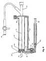
- Fig. 1illustrates the distal end of a catheter 11 having a stent 16 carried within it for implantation into the body of a patient.
- the proximal end of the catheter 11is connected to any of the delivery mechanisms to be described, and the catheter 11 is of sufficient length to reach the point of implantation of the stent 16 from the introduction point into the body.
- the catheter 11includes an outer sheath 10 , a middle tube 12 which in the preferred embodiment is formed of a compressed spring, and a flexible (e.g., polyamide) inner tube 14 .
- the outer sheath 10preferably has an ePTFE liner with a polyether blocked amide plastic (pebax) basecoat with reinforced braid, and an external layer of pebax.
- pebaxpolyether blocked amide plastic
- a stent 16 for implantation into a patientis carried within the outer sheath 10 .
- the stent 16includes a nitinol memory metal alloy frame 18 which is formed in a criss-cross pattern which may be laser cut. Most or all of the length of the stent is encapsulated within two layers of ePTFE to form a monolithic body structure 20, fully enclosing the metallic stent 16 both internally and externally where the cover 20 is present. One or both ends of the stent 16 may be left uncovered as illustrated at 22 and 24 to provide anchoring within the vessel where the stent 16 is to be implanted.
- a radiopaque atraumatic tip 26is secured to the end of the inner tube 14 of the catheter.
- the atraumatic tip 26has a rounded end and is gradually sloped to aid in the movement of the catheter through the body vessel.
- the atraumatic tip 26is radiopaque so that its location may be monitored by appropriate equipment during the surgical procedure.
- the inner tube 14is hollow so as to accommodate a guide wire, which is commonly placed in the vessel prior to insertion of the catheter, although the invention may employ a solid inner section and be used without a guide wire.
- Inner tube 14has sufficient kink resistance to engage the vascular anatomy without binding during placement and withdrawal of the delivery system.
- inner tube 14is of sufficient size and strength to allow saline injections without rupture.
- a generally cup-shaped element 28is provided within the catheter 11 adjacent the rear end of the stent 16 and is attached to the end of the spring 12 by appropriate means, e.g., the cup element 28 may be plastic wherein the spring 12 is molded into its base, or the cup element 28 may be stainless steel wherein the spring 12 is secured by welding or the like.
- the open end of the cup element 28serves to compress the end 24 of the stent 16 in order to provide a secure interface between the stent 16 and the spring 12.
- the element 28could be formed of a simple disk having either a flat or slightly concave surface for contacting the end 24 of the stent 16.
- the catheter 11In order to deploy the stent 16 inside a body vessel during a surgical procedure, the catheter 11 is introduced into the designated vessel via an introducer positioned at the skin of the patient.
- a guide wiremay have previously been introduced into the vessel, in which case the catheter 11 is introduced by passing the tip 26 over the end of the guide wire outside of the patient and moving the catheter 11 along the path within the vessel which has been established by the guide wire.
- the position of the catheter 11is tracked by monitoring the tip 26 by means of a fluoroscope.
- the catheter 11When the catheter 11 is at the desired location i.e., when the stent 16 is positioned at the location where it is be implanted, the movement of the catheter 11 is halted. The catheter 11 must then be removed, leaving the stent 16 in place at the desired location within the vessel. This is accomplished by initially retracting the outer sheath 10, i.e., towards the left in Fig. 1, until it no longer covers the stent 16.
- the spring 12is maintained in a fixed position and, in conjunction with the cup element 28 , serves to maintain the stent 16 in its desired position during the retraction of the outer sheath 10 .
- the tip 26can be pulled back through the stent 16 until the tip 26 abuts the outer sheath 10 .
- the diameter of the tip 26is slightly greater than the inner diameter of stent 16 when it is inside the outer sheath 10 .
- the stent 16will expand as it heats up to body temperature as a result of its memory metal characteristics.
- the tip 26is then pulled through the center of the stent 16 after the stent 16 has expanded following withdrawal of the sheath 10.
- the catheter 11can be removed from the vessel of the patient. This retraction procedure ensures that the tip 26 does not get caught on or embedded in any body vessel when being pulled out of the patient.
- the tube spring 12is maintained stationary during the withdrawal of the outer sheath 10 and serves to keep the stent 16 in its desired location.
- the tube spring 12is very well suited for this task since it has extremely low compression in a longitudinal direction once it is fully compressed. It is also well suited for the introduction of the catheter 11 into the body vessel, since it is extremely flexible. Alternatively, other materials, such as various plastics materials, could be employed as the middle tube 12 , so long as the compression is low to maintain stent positioning and the necessary flexibility is provided for moving through the vessel.
- the outer sheath 10In order to properly deploy the stent 16 , the outer sheath 10 must be smoothly retracted while the tube spring 12 maintains its position. A number of mechanisms are contemplated, intended to perform this operation with maximum ease of use and minimal stent migration.
- Fig. 2illustrates a first embodiment of a delivery mechanism for implanting the stent 16 .
- This mechanismis generally in the form of a V-shaped lever device having a housing shell 30 from which the outer sheath 10 extends.
- the sheath 10is secured to a pawl/sheath hub 32 .
- a spring pawl 34 attached to the hub 32engages a ratchet 36 which is integrated into the housing shell 30 . Movement of the sheath hub 32 within the housing shell 30 is thus constrained to moving to the right as shown in Fig. 2.
- the tube spring 12is secured in a fixed position to a guide wire port 38.
- the interior of the devicemay be flushed by means of a flush stop cock 40.
- a ratchet rail 42is provided at the bottom of the housing shell 30 and is reciprocal back and forth within the shell 30 .
- the rail 42includes ratchet teeth 44 on the upper side which engage with the spring pawl 34 and a rack gear 46 on the bottom surface thereof which engages a pinion 48 .
- the pinion 48is rotated by means of a lever handle 50 which includes a drive gear 52 .
- the lever handle 50is spring biased by means of a spring 54 to its open position.
- Other types of springs, such as a spring contained within the pivot point 56 of the lever handlecould alternatively be employed.
- the handle 50is in its open position, which forms an angle of approximately twenty-five degrees with the housing shell 30 .
- the drive gear 52rotates the pinion 48 in a clockwise direction as illustrated by arrow 60.
- the pinion 48drives the rail 42 to the right, which in turn drives the sheath hub 32 to the right, thus extracting the outer sheath 10 by an incremental distance illustrated at 62. In the described device, the incremental distance is approximately 1 cm.
- the handle 50when the handle 50 is released, the spring action returns it to the open position, thus rotating the pinion 48 counterclockwise and returning the rail 42 to its leftward position.
- the sheath hub 32is maintained stationary by the ratchet 36 .
- Fig. 6illustrates the mechanism in which the handle 50 has been operated to move the hub 32 , and therefore the outer sheath 10 , back to its completely rightmost position. In this position (or sooner depending upon the length of the stent) the outer sheath 10 will be completely away from the stent 16 , allowing the stent 16 to expand. As described above, once the stent 16 expands, the inner tube 14 and tip 26 are pulled back through the middle of the stent 16 until the tip 26 is tight against the outer sheath 10 . The entire catheter 11 can then be removed, leaving the stent 16 in place at the desired location.
- FIG. 7A preferred embodiment of the device shown in Fig. 2 is illustrated by the exploded view in Fig. 7.
- a left housing assembly 31 and a right housing assembly 33can be seen.
- An inner catheter assembly 37is disposed between the housing assemblies 31 and 33 to support the tube spring 12 as well as the spring pawl 34 .
- a strain relief member 51fits over the end of housing shell 30 to reduce any potential pressure caused in the actuation of the mechanism.
- a safety pin 53is insertable into the lever handle 50 for additional protection.
- the inner catheter assembly 37which is coupled to the inner tube 14 , is pulled back away from the housing assemblies 31 and 33 in order to retract the inner tube 14 far enough so that tip 26 is snuggly against the outer sheath 10 .
- the catheter 11including the outer sheath 10 , the inner tube 14 and the tip 26 can then be removed from the body. Retraction of the catheter 11 in this manner ensures that the tip 26 can not get caught on anything outside of the body or inside the delivery mechanism.
- the gear mechanism including the lever gear 52 , pinion 48 and rack 46is designed to provide a mechanical advantage of approximately 4:1.
- the mechanical advantage along with the rotating pinion configurationprovides very smooth and linear operation with minimal fly back during the return stroke.
- the lever handle configurationis extremely convenient, as it can be easily operated in almost any rotational orientation. This is important due to the fact that when a catheter is introduced into the patient, it is often necessary to rotate the catheter in order for it to most easily follow the desired path through the vessel to the stent location. Therefore, the final orientation when the stent is to be deployed is variable.
- the configuration of the V-shaped lever handle mechanismenables a simple gripping action to be applied, and is easily gripped by the surgeon regardless of its final orientation.
- FIG. 8A second embodiment of the stent delivery mechanism is illustrated in Fig. 8.
- This delivery mechanismemploys a hydraulic system to achieve extremely smooth operation.
- a housing 62defines a reservoir chamber 64 within which is carried a piston 66 .
- the outer sheath 10is connected to the piston 66 to be moved therewith.
- a V-cup seal 68prevents leakage of the hydraulic fluid carried within the housing.
- a piston displacement chamber 70is defined between the piston 66 and the opening through which the sheath 10 exits.
- Conduits 72 and 74are coupled to opposite ends of the piston housing 62 .
- Directional check valves 76 and 78are contained within the conduits 72 and 74 , respectively.
- a drive plunger 80is contained within a plunger housing 82 .
- Hydraulic fluidsuch as saline solution, is provided through a port 84 .
- Figs. 9-12the reservoir 64 is filled with fluid and the system is ready for operation.
- the plunger 80is pulled rearward and transfers saline from the reservoir 64 through the conduit 72 via valve 76 .
- the valve 76is open in this state and the valve 78 is closed.
- the plunger 80is pressed inward to open the valve 78 and move fluid through the conduit 74 into the piston chamber 70 , thus moving the piston 66 to the right by a fixed amount and, in turn, retracting the outer sheath 10 from the stent.
- one stroke of the plunger 80provides approximately 1 cm of travel of the piston 66 .
- the plunger and pistonare sized to provide a mechanical advantage of approximately 4:1.
- a lever or trigger mechanismcould be employed to actuate the plunger 80 .
- Such mechanismwould include a spring return or the like to bias the plunger to the extended position.
- the use of a lever mechanismin which case the plunger orientation would be reversed and a lever handle coupled to it) would allow grip pressure to be utilized as opposed to finger or thumb pressure.
- FIG. 13a third embodiment of the invention will be described.
- This embodimentemploys a rack and pinion mechanism actuated by means of a thumb knob.
- the deviceincludes a housing 82 within which is carried a rack 84 , movable from left to right as illustrated in Figs. 15 and 16.
- the rack 84interacts with a rack drive gear 86 coupled to a reduction drive gear 88 , which in turn is driven by a knob 90 having a gear 92 .
- the outer sheath 10is coupled to the rack 84 to be movable therewith.
- Fig. 14is a cross-sectional view of Fig. 13 along line 14-14, showing a different perspective of knob 90 in relation to housing 82 .
- the knob 90is rotated counterclockwise as illustrated in Fig. 15, causing the gear 92 to move in the same direction.
- This actioncauses the reduction drive gear 88 and the rack drive gear 86 to move in a clockwise position, which in turn causes the rack 84 to retract within the housing by a distance of approximately 1 cm per revolution of the knob as indicated at 94 .
- the mechanical advantageis controlled by appropriate sizing of the gears which drive the rack 84 . After a sufficient number of rotations, the rack 84 will be fully retracted, as illustrated in Fig. 16 and the outer sheath 10 will be completely removed from the stent 16 so that the catheter 11 can be removed from the patient as described above.
- a fourth embodiment of the delivery systemwill be described.
- a power screw drive systemis employed.
- a drive knob 96is carried within a collar 98 of a housing 100 .
- the drive knob 96is fixed to a power nut 102 having a threaded interior surface which mates with the threaded surface of a power screw 104 which is slidably carried within the housing 100 .
- the outer sheath 10is coupled to the power screw 104 to move in conjunction therewith.
- the power nut 102rotates and drives the power screw 104 to the right as shown in the Figs. 19 and 20.
- Fig. 18is an end plan view, illustrating the drive knob 96 within the collar 98 .
- the mechanical advantage of this fourth embodimentis determined by the pitch of the power screw 104 and the size of the knob 96 .
- a single rotation of the knob 96achieves a movement of the power screw 104 of approximately 1 cm, as indicated at 106 .
- the high mechanical advantage provided by the configurationfacilitates smooth retraction of the outer sheath 10 .
- the power screw 104will be fully retracted, as illustrated in Fig. 20, and the outer sheath 10 will be completely withdrawn from the stent 16 .
- the catheter 11can then be removed as described above.
- each of the disclosed systemsprovides a significant mechanical advantage which facilitates smooth retraction of the outer sheath 10 which covers the stent 16 . This minimizes migration of the stent 10 during sheath retraction, thus ensuring that the stent 16 will remain in its desired location.
- various configurationsare provided which are operable in numerous orientations, thus providing convenient and simple use during surgery.
- a shape memory metal stenthas been illustrated as being the type of stent that is to be delivered by the delivery mechanism of the present invention. It should be apparent, however, that the inventive concepts described above would be equally applicable to other types of expandable stents.
- the words used in this specification to describe the invention and its various embodimentsare to be understood not only in the sense of their commonly defined meanings, but to include by special definition in this specification structure, material or acts beyond the scope of the commonly defined meanings.
Landscapes
- Health & Medical Sciences (AREA)
- Engineering & Computer Science (AREA)
- Biomedical Technology (AREA)
- Cardiology (AREA)
- Oral & Maxillofacial Surgery (AREA)
- Transplantation (AREA)
- Heart & Thoracic Surgery (AREA)
- Vascular Medicine (AREA)
- Life Sciences & Earth Sciences (AREA)
- Animal Behavior & Ethology (AREA)
- General Health & Medical Sciences (AREA)
- Public Health (AREA)
- Veterinary Medicine (AREA)
- Media Introduction/Drainage Providing Device (AREA)
- Prostheses (AREA)
Abstract

Description
- The present invention relates to implantable medical devices. Moreparticularly, the present invention relates to mechanisms for implanting aself-expanding stent graft which is used to sustain a weakened bodyvessel.
- Various diseases of blood vessels or hollow organs cause astenosis or complete occlusion of their lumen, which results in a decreaseor complete loss of their functional attributes. Various implantableprosthetic devices for sustaining a blood vessel or hollow organ lumentypically have a tubular-shaped frame body which is introduced into thevessel or hollow organ and fixed in the necessary location to sustain thelumen.
- A commonly used implant is a tubular-shaped wire frame known asa stent graft. In one type of stent graft, the wire frame is made of self-expandingnickel-titanium (nitinol) shape memory alloy which is laser cutand encapsulated within two layers of expanded polytetrafluoroethylene(ePTFE). The layers of ePTFE are processed such that the material formsa monolithic structure, fully enclosing the metallic stent where the cover ispresent. The encapsulation is intended to prevent restenosis of thevessel. The inner blood contacting lumen of the stent graft is impregnatedwith carbon. Typically, one or both ends of the stent graft is flared andfree of encapsulation in order to facilitate anchoring within the vessel. Thenitinol alloy is placed into the body during surgery at room temperature.As it increases to body temperature, it expands to its desired size. Balloonangioplasty may be done after implantation of the stent to set its finalshape.
- In order to introduce the stent into the body vessel, it is placedwithin a tubular sheath catheter. When the device is positioned at thedesired location, it is released from the tubular sheath and permitted toexpand radially against the wall of the vessel. When the outer sheath isremoved, the physician must be careful to avoid migration of the stentaway from the desired location. Typical prior art devices employ a simpleratchet mechanism in conjunction with the outer sheath and an innerlumen. The inner lumen is maintained stationary to fix the stent in positionand the outer lumen is drawn away from the stent by means of the ratchetmechanism actuated by a spring loaded trigger. Each pull on the triggercauses the outer sheath to retract by an amount corresponding to thestroke of the trigger. An anchor to which the outer sheath is attachedincludes a tooth which engages with each tooth of the ratchet mechanism.This mechanism has drawbacks in that it is awkward to operate anddifficult to maintain steady so that the stent graft does not migrate awayfrom its desired position during sheath retraction.
- The present invention is directed to a stent delivery mechanismwhich is both easy to operate and facilitates extremely precise stentpositioning. Several different configurations are described. In the firstembodiment, a simple V-shaped grip aligned generally longitudinally withthe catheter to be deployed is utilized. A mechanical advantage gearmechanism is employed, which operates in conjunction with a ratchet tosmoothly retract a sheath hub to which the outer sheath of the catheter isattached. The mechanism is easy to grasp and actuate in any rotationalconfiguration. The V-shaped mechanism includes a body which containsthe ratchet and a drive gear lever handle. The lever handle interacts witha drive pinion to drive the ratchet by a predetermined amount, thusretracting the sheath hub by a corresponding amount. The drive gearlever handle mechanism provides both the mechanical advantage, which results in movement of the outer sheath by a relatively small amount for alarge displacement of the lever handle, and a much smoother operationthan the direct ratchet operation of the prior art device.
- A second embodiment employs a hydraulicmechanism to both provide the mechanical advantage and achieveextremely smooth retraction operation. In addition, the use of hydraulics,as opposed to other systems, creates positive positioning so that theactuator will not cause any unexpected motion. The hydraulic system maybe actuated by means of a drive plunger similar to the operation of asyringe, or may be equipped with a lever handle to allow a gripping actionto be employed for actuation.
- In a third embodiment, a rack and pinion drive system operated bya thumb wheel is employed. The rack and pinion drive system alsoprovides a desirable mechanical advantage and promotes smoothoperation.
- In a fourth embodiment, a power screw drive system is employed.This drive system is actuated by a thumb driven concentric drive knobwhich rotates to retract an internal power screw to which the outer sheathis secured. Again, a mechanical advantage is provided to promote smooth.retraction of the outer sheath.
- In order to further facilitate the stent deployment, the inner lumen ofthe delivery system may be formed of a metal spring, which is containedin its fully compressed state. The use of such a spring for the inner lumenprovides significant advantages in that it is extremely flexible, enablingintroduction of the catheter into the body and proper positioning of thestent, and yet is very rigid and non-compressible so as to maintain thestent in the desired position during outer sheath retraction.
- The invention will be described by reference to the accompanyingdrawings, wherein:
- Fig. 1 is a cross-sectional view of the end of a catheter illustrating astent to be implanted;
- Fig. 2 is a cross-sectional view of a first embodiment of a stentdelivery mechanism incorporating a moving railmechanism;
- Figs. 3-6 are cross-sectional views illustrating the retractionoperation of the moving rail system;
- Fig. 7 is an exploded view of a preferred embodiment of the stentdelivery mechanism shown in Fig. 2.
- Fig. 8 is a cross-sectional view of a second embodiment of thestent delivery mechanism of the present invention incorporating ahydraulic mechanism
- Figs. 9-12 are cross-sectional views illustrating the operation of theembodiment of Fig. 7;
- Fig. 13 is a cross-sectional view of a third embodiment of a stentdelivery mechanism employing a rack and pinionthumb actuated drive system;
- Fig. 14 is a view of the system of Fig. 13 along line 14-14;
- Figs. 15 and 16 are cross-sectional views illustrating the operationof the drive system of Fig. 13;
- Fig. 17 is a cross-sectional view of a fourth embodiment of astent delivery mechanism employing a powerscrew drive system;
- Fig. 18 is an end plan view illustrating the drive knob and collarconfiguration of the system of Fig. 17; and
- Figs. 19 and 20 are cross-sectional views illustrating the operationof the power screw drive system of Fig. 17.
- The following description is of the best presently contemplatedmodes of carrying out the invention. The description is made for illustrating the general principles of the invention and is not to be taken ina limiting sense.
- Fig. 1 illustrates the distal end of a catheter11 having a stent16carried within it for implantation into the body of a patient. The proximalend of the catheter11 is connected to any of the delivery mechanisms tobe described, and the catheter11 is of sufficient length to reach the pointof implantation of the stent16 from the introduction point into the body.The catheter11 includes an
outer sheath 10, amiddle tube 12 which inthe preferred embodiment is formed of a compressed spring, and aflexible (e.g., polyamide)inner tube 14. Theouter sheath 10 preferablyhas an ePTFE liner with a polyether blocked amide plastic (pebax)basecoat with reinforced braid, and an external layer of pebax. A stent16for implantation into a patient is carried within theouter sheath 10. Thestent16 includes a nitinol memorymetal alloy frame 18 which is formed ina criss-cross pattern which may be laser cut. Most or all of the length ofthe stent is encapsulated within two layers of ePTFE to form amonolithicbody structure 20, fully enclosing the metallic stent16 both internally andexternally where thecover 20 is present. One or both ends of the stent16may be left uncovered as illustrated at22 and24 to provide anchoringwithin the vessel where the stent16 is to be implanted. - A radiopaque
atraumatic tip 26 is secured to the end of theinnertube 14 of the catheter. Theatraumatic tip 26 has a rounded end and isgradually sloped to aid in the movement of the catheter through the bodyvessel. Theatraumatic tip 26 is radiopaque so that its location may bemonitored by appropriate equipment during the surgical procedure. Theinner tube 14 is hollow so as to accommodate a guide wire, which iscommonly placed in the vessel prior to insertion of the catheter, althoughthe invention may employ a solid inner section and be used without aguide wire.Inner tube 14 has sufficient kink resistance to engage thevascular anatomy without binding during placement and withdrawal of the delivery system. In addition,inner tube 14 is of sufficient size and strengthto allow saline injections without rupture. - A generally cup-shaped
element 28 is provided within the catheter11 adjacent the rear end of the stent16 and is attached to the end of thespring 12 by appropriate means, e.g., thecup element 28 may be plasticwherein thespring 12 is molded into its base, or thecup element 28 maybe stainless steel wherein thespring 12 is secured by welding or the like.The open end of thecup element 28 serves to compress theend 24 of thestent16 in order to provide a secure interface between the stent16 andthespring 12. Alternatively, instead of a cup shape, theelement 28 couldbe formed of a simple disk having either a flat or slightly concave surfacefor contacting theend 24 of the stent16. - In order to deploy the stent16 inside a body vessel during asurgical procedure, the catheter11 is introduced into the designatedvessel via an introducer positioned at the skin of the patient. Asmentioned above, a guide wire may have previously been introduced intothe vessel, in which case the catheter11 is introduced by passing the
tip 26 over the end of the guide wire outside of the patient and moving thecatheter11 along the path within the vessel which has been establishedby the guide wire. - The position of the catheter11 is tracked by monitoring the
tip 26by means of a fluoroscope. When the catheter11 is at the desiredlocation i.e., when the stent16 is positioned at the location where it is beimplanted, the movement of the catheter11 is halted. The catheter11must then be removed, leaving the stent16 in place at the desiredlocation within the vessel. This is accomplished by initially retracting theouter sheath 10, i.e., towards the left in Fig. 1, until it no longer covers thestent16. Thespring 12 is maintained in a fixed position and, inconjunction with thecup element 28, serves to maintain the stent16 in itsdesired position during the retraction of theouter sheath 10. After theouter sheath 10 has been retracted such that it no longer covers the stent16 and the stent16 is expanded, thetip 26 can be pulled back throughthe stent16 until thetip 26 abuts theouter sheath 10. As illustrated, thediameter of thetip 26 is slightly greater than the inner diameter of stent16when it is inside theouter sheath 10. The stent16 will expand as it heatsup to body temperature as a result of its memory metal characteristics.Thetip 26 is then pulled through the center of the stent16 after the stent16 has expanded following withdrawal of thesheath 10. Once thetip 26has been pulled back against theouter sheath 10, the catheter11 can beremoved from the vessel of the patient. This retraction procedure ensuresthat thetip 26 does not get caught on or embedded in any body vesselwhen being pulled out of the patient. - As discussed above, the
tube spring 12 is maintained stationaryduring the withdrawal of theouter sheath 10 and serves to keep the stent16 in its desired location. Thetube spring 12 is very well suited for thistask since it has extremely low compression in a longitudinal directiononce it is fully compressed. It is also well suited for the introduction of thecatheter11 into the body vessel, since it is extremely flexible.Alternatively, other materials, such as various plastics materials, could beemployed as themiddle tube 12, so long as the compression is low tomaintain stent positioning and the necessary flexibility is provided formoving through the vessel. In order to properly deploy the stent16, theouter sheath 10 must be smoothly retracted while thetube spring 12maintains its position. A number ofmechanisms are contemplated, intended to perform this operation with maximum ease ofuse and minimal stent migration. - Fig. 2 illustrates a first embodiment of a delivery mechanism forimplanting the stent16. This mechanism is generally in the form of a V-shapedlever device having a
housing shell 30 from which theoutersheath 10 extends. Thesheath 10 is secured to a pawl/sheath hub 32. Aspring pawl 34 attached to thehub 32 engages aratchet 36 which isintegrated into thehousing shell 30. Movement of thesheath hub 32 within thehousing shell 30 is thus constrained to moving to the right asshown in Fig. 2. Thetube spring 12 is secured in a fixed position to aguide wire port 38. The interior of the device may be flushed by means ofaflush stop cock 40. Aratchet rail 42 is provided at the bottom of thehousing shell 30 and is reciprocal back and forth within theshell 30. Therail 42 includesratchet teeth 44 on the upper side which engage with thespring pawl 34 and arack gear 46 on the bottom surface thereof whichengages apinion 48. Thepinion 48 is rotated by means of alever handle 50 which includes adrive gear 52. The lever handle50 is spring biased bymeans of a spring54 to its open position. Other types of springs, such asa spring contained within thepivot point 56 of the lever handle couldalternatively be employed. - The operation of the device of Fig. 2 will be described withreference to Figs. 3-6. Initially, as illustrated in Fig. 3, the
handle 50 is inits open position, which forms an angle of approximately twenty-fivedegrees with thehousing shell 30. When the handle is squeezed, bringingit adjacent to the housing shell as indicated byarrow 58 in Fig. 4, thedrivegear 52 rotates thepinion 48 in a clockwise direction as illustrated byarrow 60. Thepinion 48 drives therail 42 to the right, which in turn drivesthesheath hub 32 to the right, thus extracting theouter sheath 10 by anincremental distance illustrated at62. In the described device, theincremental distance is approximately 1 cm. Referring to Fig. 5, when thehandle 50 is released, the spring action returns it to the open position,thus rotating thepinion 48 counterclockwise and returning therail 42 to itsleftward position. Thesheath hub 32 is maintained stationary by theratchet 36. - The described device is intended for use with stents ofapproximately 40-100 mm in length. In order to fully retract the
outersheath 10, the lever handle50 must be closed and opened a number oftimes. Fig. 6 illustrates the mechanism in which thehandle 50 has beenoperated to move thehub 32, and therefore theouter sheath 10, back to its completely rightmost position. In this position (or sooner dependingupon the length of the stent) theouter sheath 10 will be completely awayfrom the stent16, allowing the stent16 to expand. As described above,once the stent16 expands, theinner tube 14 andtip 26 are pulled backthrough the middle of the stent16 until thetip 26 is tight against theoutersheath 10. The entire catheter 11 can then be removed, leaving the stent16 in place at the desired location. - A preferred embodiment of the device shown in Fig. 2 is illustratedby the exploded view in Fig. 7. In this view, a
left housing assembly 31and aright housing assembly 33 can be seen. Aninner catheter assembly 37 is disposed between thehousing assemblies tube spring 12 as well as thespring pawl 34. Astrain relief member 51 fitsover the end ofhousing shell 30 to reduce any potential pressure causedin the actuation of the mechanism. Asafety pin 53 is insertable into thelever handle50 for additional protection. Upon completion of thedeployment of the stent16 and the retraction ofouter sheath 10, aretractor sleeve 49 is pulled back slightly, releasing aretractor latch 47from its locked position on theinner catheter assembly 37. Theinnercatheter assembly 37, which is coupled to theinner tube 14, is pulledback away from thehousing assemblies inner tube 14 far enough so thattip 26 is snuggly against theouter sheath 10. The catheter11, including theouter sheath 10, theinner tube 14 andthetip 26 can then be removed from the body. Retraction of the catheter11 in this manner ensures that thetip 26 can not get caught on anythingoutside of the body or inside the delivery mechanism. - The gear mechanism including the
lever gear 52,pinion 48 andrack 46 is designed to provide a mechanical advantage of approximately4:1. The mechanical advantage along with the rotating pinionconfiguration provides very smooth and linear operation with minimal flyback during the return stroke. In addition, the lever handle configuration isextremely convenient, as it can be easily operated in almost any rotational orientation. This is important due to the fact that when a catheter isintroduced into the patient, it is often necessary to rotate the catheter inorder for it to most easily follow the desired path through the vessel to thestent location. Therefore, the final orientation when the stent is to bedeployed is variable. The configuration of the V-shaped lever handlemechanism enables a simple gripping action to be applied, and is easilygripped by the surgeon regardless of its final orientation. Generally,approximately ten cycles (i.e., squeezing and releasing) of the leverhandle50 are necessary to fully remove theouter sheath 10 from thestent. The configuration of this embodiment enables retraction to be donein a very smooth and linear fashion. - A second embodiment of the stent delivery mechanism isillustrated in Fig. 8. This delivery mechanism employs a hydraulic systemto achieve extremely smooth operation. A
housing 62 defines areservoirchamber 64 within which is carried apiston 66. Theouter sheath 10 isconnected to thepiston 66 to be moved therewith. A V-cup seal 68prevents leakage of the hydraulic fluid carried within the housing. Apistondisplacement chamber 70 is defined between thepiston 66 and theopening through which thesheath 10 exits. Conduits pistonhousing 62.Directional check valves conduits drive plunger 80 is contained within aplunger housing 82. Hydraulic fluid, such as saline solution, is providedthrough aport 84.- The operation of the hydraulic mechanism will be described withreference to Figs. 9-12. In Fig. 9, the
reservoir 64 is filled with fluid andthe system is ready for operation. In Fig. 10, theplunger 80 is pulledrearward and transfers saline from thereservoir 64 through theconduit 72viavalve 76. Thevalve 76 is open in this state and thevalve 78 is closed. - Referring to Fig. 11, the
plunger 80 is pressed inward to open thevalve 78 and move fluid through theconduit 74 into thepiston chamber 70, thus moving thepiston 66 to the right by a fixed amount and, in turn,retracting theouter sheath 10 from the stent. In the present embodiment,one stroke of theplunger 80 provides approximately 1 cm of travel of thepiston 66. The plunger and piston are sized to provide a mechanicaladvantage of approximately 4:1. By repeatedly operating the plunger, thepiston 66 will be drawn back to its fully deployed position as illustrated inFig.12. At this point, theouter sheath 10 is fully withdrawn from the stent16, and the catheter 11 can be pulled out of the patient as describedabove. - Although the described embodiment employs a plunger which ismanually operated, a lever or trigger mechanism could be employed toactuate the
plunger 80. Such mechanism would include a spring return orthe like to bias the plunger to the extended position. The use of a levermechanism (in which case the plunger orientation would be reversed anda lever handle coupled to it) would allow grip pressure to be utilized asopposed to finger or thumb pressure. - Referring to Figs. 13-16, a third embodiment of the invention will bedescribed. This embodiment employs a rack and pinion mechanismactuated by means of a thumb knob. In Fig. 13, the device includes a
housing 82 within which is carried arack 84, movable from left to right asillustrated in Figs. 15 and 16. Therack 84 interacts with arack drive gear 86 coupled to areduction drive gear 88, which in turn is driven by aknob 90 having agear 92. Theouter sheath 10 is coupled to therack 84 to bemovable therewith. Fig. 14 is a cross-sectional view of Fig. 13 along line14-14, showing a different perspective ofknob 90 in relation tohousing 82. - In operation, the
knob 90 is rotated counterclockwise as illustratedin Fig. 15, causing thegear 92 to move in the same direction. This actioncauses thereduction drive gear 88 and therack drive gear 86 to move ina clockwise position, which in turn causes therack 84 to retract within thehousing by a distance of approximately 1 cm per revolution of the knob as indicated at94. The mechanical advantage is controlled by appropriatesizing of the gears which drive therack 84. After a sufficient number ofrotations, therack 84 will be fully retracted, as illustrated in Fig. 16 andtheouter sheath 10 will be completely removed from the stent16 so thatthe catheter11 can be removed from the patient as described above. - Referring to Figs. 17-20, a fourth embodiment of the deliverysystem will be described. In this embodiment, a power screw drive systemis employed. A
drive knob 96 is carried within acollar 98 of ahousing 100. Thedrive knob 96 is fixed to apower nut 102 having a threadedinterior surface which mates with the threaded surface of apower screw 104 which is slidably carried within thehousing 100. Theouter sheath 10is coupled to thepower screw 104 to move in conjunction therewith. Byrotating thedrive knob 96, thepower nut 102 rotates and drives thepowerscrew 104 to the right as shown in the Figs. 19 and 20. Fig. 18 is an endplan view, illustrating thedrive knob 96 within thecollar 98. Themechanical advantage of this fourth embodiment is determined by thepitch of thepower screw 104 and the size of theknob 96. - As shown in Fig. 19, a single rotation of the
knob 96 achieves amovement of thepower screw 104 of approximately 1 cm, as indicated at106. The high mechanical advantage provided by the configurationfacilitates smooth retraction of theouter sheath 10. After a number ofrotations of theknob 96, thepower screw 104 will be fully retracted, asillustrated in Fig. 20, and theouter sheath 10 will be completely withdrawnfrom the stent16. The catheter11 can then be removed as describedabove. - In summary, each of the disclosed systems provides a significantmechanical advantage which facilitates smooth retraction of the
outersheath 10 which covers the stent16. This minimizes migration of thestent 10 during sheath retraction, thus ensuring that the stent16 will remain inits desired location. In addition, various configurations are provided which are operable in numerous orientations, thus providing convenient andsimple use during surgery. - Many alterations and modifications may be made by those havingordinary skill in the art without departing from the scope of thepresent invention. For example, a shape memory metal stent has beenillustrated as being the type of stent that is to be delivered by the deliverymechanism of the present invention. It should be apparent, however, thatthe inventive concepts described above would be equally applicable toother types of expandable stents. Moreover, the words used in thisspecification to describe the invention and its various embodiments are tobe understood not only in the sense of their commonly defined meanings,but to include by special definition in this specification structure, materialor acts beyond the scope of the commonly defined meanings. Thus, if anelement can be understood in the context of this specification as includingmore than one meaning, then its use in a claim must be understood asbeing generic to all possible meanings supported by the specification andby the word itself. The definitions of the words or elements of the followingclaims are, therefore, defined in this specification to include not only thecombination of elements which are literally set forth, but all equivalentstructure, material or acts for performing substantially the same function insubstantially the same way to obtain substantially the same result. Thedescribed embodiments are to be considered illustrative rather thanrestrictive. The invention is defined by the following claims.
Claims (44)
- An apparatus for introducing a stent into a bodyvessel, comprising:characterized in that:a housing, providing a passage therein;a movable member disposed within said passage;actuating means for moving said movable member in thepassage;a catheter comprising an outer sheath (10) coupled tosaid movable member to move the outer sheath along with themoving member;an inner tube extending through said catheter; anda stabilizing element for maintaining the position ofa stent during movement of the outer sheath;said movable member comprises a power screw that hasa threaded exterior surface and said actuating meanscomprises a power nut, wherein said power nut has athreaded interior surface that mates with the threadedexterior surface of the power screw, and relative rotationbetween the power nut and power screw causes the movablemember to move in said passage.
- The apparatus according to Claim 1, wherein saidstabilizing element extends through the catheter betweenthe inner tube and outer sheath and comprises a tube springcoupled to a holding member, wherein said holding membergrips a proximal end of the stent.
- The apparatus according to Claim 2, wherein saidholding member is cup-shaped.
- The apparatus according to Claim 1, further comprisinga tip (26) attached to a distal end of the inner tube, andwherein said tip is radiopaque.
- The apparatus according to Claim 1, further comprisinga withdrawing element for proximally withdrawing said innertube and a locking mechanism, wherein said withdrawingelement is attached to said inner tube and said lockingmechanism is releasably coupled to said withdrawingelement.
- The apparatus according to Claim 1, further comprising:a plunger chamber coupled to said housing;an inlet conduit providing a path for fluid from saidplunger chamber to said housing, including a directionalcheck valve;an outlet conduit providing a path for fluid from saidhousing to said plunger chamber, including a directionalcheck valve; anda fluid port for inserting fluid into said housing.
- The apparatus according to Claim 1, wherein saidactuating means further comprises a drive knob coupled tothe power nut.
- An apparatus for introducing a stent into a bodyvessel, comprising:an elongated housing, providing a passage therein;a movable member disposed within said passage;actuating means coupled to said housing for incrementallymoving said movable member in a first direction;a catheter coupled to said movable member,an inner tube extending through said catheter,a tip attached to said inner tube; anda stabilizing element extending through said catheter formaintaining the position of the stent during retractionof said catheter.
- The apparatus according to Claim 8, wherein saidstabilizing element comprises a tube spring coupled to aholding member, wherein said holding member grips aproximal end of the stent.
- The apparatus according to Claim 9, wherein saidholding member is cup-shaped.
- The apparatus according to Claim 8, wherein said tipis radiopaque.
- The apparatus according to Claim 8, wherein saidhousing further comprises a stationary ratchet on a firstside, a movable ratchet on a second side directly oppositesaid first side, and a pinion engaging said movableratchet.
- The apparatus according to Claim 12, wherein saidmovable member comprises a pawl hub, including a first andsecond spring pawl, wherein said first spring pawl is located on a first side of said pawl hub engaging saidstationary ratchet, and said second spring pawl is locatedon a second side directly opposite said first side of saidpawl hub engaging said movable ratchet.
- The apparatus according to Claim 12, wherein saidactuating means comprises a lever handle coupled to saidhousing including a drive gear engaging said pinion.
- The apparatus according to Claim 12, furthercomprising a withdrawing element for proximally withdrawingsaid inner tube and a locking mechanism, wherein saidwithdrawing element is attached to said inner tube and saidlocking mechanism is releasably coupled to said withdrawingelement.
- The apparatus deployment system according 14, furthercomprising a spring disposed between said housing and saidlevel handle, biasing said lever handle in an openposition.
- The apparatus according to Claim 8, further comprising:a plunger chamber coupled to said housing;an inlet conduit providing a path for fluid from saidplunger chamber to said housing, including a directionalcheck valve;an outlet conduit providing a path for fluid from saidhousing to said plunger chamber, including a directionalcheck valve; anda fluid port for inserting fluid into said housing.
- The apparatus according to Claim 17, wherein saidmovable member comprises a piston.
- The apparatus according to Claim 17, wherein saidactuating means comprises a plunger disposed within saidplunger chamber for moving fluids to and from said housing.
- The apparatus according to Claim 8, further comprisinga rack drive gear coupled to a reduction drive gear,wherein said rack drive gear engages said movable member.
- The apparatus according to Claim 20, wherein saidmovable member comprises a rack element.
- The apparatus according to Claim 20, wherein saidactuating means comprises knob coupled to a knob gear,wherein said knob gear engages said reduction drive gear.
- The apparatus according to Claim 8, wherein saidmovable member comprises a power screw that has a threadedexterior surface.
- The apparatus according to Claim 23, wherein saidactuating means comprises a drive knob coupled to a powernut, wherein said power nut has a threaded interior surfacethat mates with the threaded exterior surface of said powerscrew.
- An apparatus for introducing a stent into a bodyvessel, comprising:an elongated housing, providing a passage therein, whereinsaid housing further comprises a stationary ratchet ona first side, a movable ratchet on a second sidedirectly opposite said first side, and a pinion engagingsaid movable ratchet;a pawl hub disposed within said passage, including a firstand second spring pawl, wherein said first springpawl is located on a first side of said pawl hubengaging said stationary ratchet, and said secondspring pawl is located on a second side directlyopposite said first side of said pawl hub engagingsaid movable ratchet;a lever handle coupled to said housing, including a drivegear engaging said pinion;a catheter coupled to said pawl hub,an inner tube extending through said catheter;a tip attached to said inner tube; anda stabilizing element extending through said catheter formaintaining the position of the stent during retractionof said catheter.
- The apparatus according to Claim 25, wherein saidstabilizing element comprises a tube spring coupled to aholding member, wherein said holding member grips aproximal end of the stent.
- The apparatus according to Claim 26, wherein saidholding member is cup-shaped.
- The apparatus according to Claim 25, furthercomprising a spring disposed between said housing and saidlever handle, biasing said lever handle in an openposition.
- The apparatus according to Claim 25, further comprisinga withdrawing element for proximally withdrawing said innertube and a locking mechanism, wherein said withdrawingelement is attached to said inner tube and said lockingmechanism is releasably coupled to said withdrawingelement.
- The apparatus according to any one of Claim 25,wherein said tip is radiopaque.
- An apparatus for introducing a stent into a bodyvessel, comprising:an elongated housing, providing a passage thereinincluding a port for inserting fluid;a piston disposed within said passage;a plunger chamber coupled to said housing;an inlet conduit providing a path for fluid from saidplunger chamber to said housing, including a directionalcheck valve;an outlet conduit providing a path for fluid from saidhousing to said plunger chamber, including a directionalcheck valve;a plunger disposed within said plunger chamber for moving fluids to and from said housing;a catheter coupled to said piston,an inner tube extending through said catheter;a tip attached to said inner tube; anda stabilizing element extending through said catheterfor maintaining the position of the stent during retractionof said catheter.
- The apparatus according to Claim 31, wherein saidstabilizing element comprises a tube spring coupled to aholding member, wherein said holding member grips aproximal end of the stent.
- The apparatus according to Claim 32, wherein saidholding member is cup-shaped.
- The apparatus according to Claim 31, wherein said tipis radiopaque.
- An apparatus for introducing a stent into a bodyvessel, comprising:an elongated housing, providing a passage therein;a rack element disposed within said passage;a reduction drive gear coupled to said housing;a rack drive gear coupled to said reduction drivegear, wherein said rack drive gear engages said rackelement;a knob including a knob gear, wherein said knobgear engages said reduction drive gear;a catheter coupled to said rack element,an inner tube extending through said catheter;a tip attached to said inner tube; anda stabilizing element extending through saidcatheter for maintaining the position of the stent duringretraction of said catheter.
- The apparatus according to Claim 35, wherein saidstabilizing element comprises a tube spring coupled to aholding member, wherein said holding member grips aproximal end of the stent.
- The apparatus according to Claim 36, wherein saidholding member is cup-shaped.
- The apparatus according to Claim 35, wherein said tipis radiopaque.
- An apparatus for introducing a stent into a bodyvessel, comprising:an elongated housing, providing a passage therein;a power screw disposed within said passage, including athreaded exterior surface;a drive knob coupled to said housing;a power nut coupled to said drive knob, wherein said powernut has a threaded interior surface that mates withthe threaded exterior surface of said power screw;a catheter coupled to said power screw,an inner tube extending through said catheter;a tip attached to said inner tube; anda stabilizing element extending through said catheter formaintaining the position of the stent during retractionof said catheter.
- The apparatus according to Claim 39, wherein saidstabilizing element comprises a tube spring coupled to aholding member, wherein said holding member grips aproximal end of the stent.
- The apparatus according to Claim 40, wherein saidholding member is cup-shaped.
- The apparatus according to Claim 39, wherein said tipis radiopaque.
- A method for introducing a stent into a body vesselusing a delivery mechanism including a catheter, whereinsaid catheter has an outer sheath, wherein an inner tubeand a stabilizing element extend through said catheter, andwherein a tip is coupled to a distal end of said innertube, comprising the steps of:loading the stent into a distal end of the catheter, whereinthe stent is coupled to the stabilizing element, andwherein a portion of said tip extends beyond thedistal end of said catheter;inserting said catheter into the body vessel to a desiredlocation;activating said delivery mechanism, wherein said outersheath is incrementally retracted while said stent ismaintained in position by said stabilizing element;removing said catheter from the body vessel;expanding said stent; andwithdrawing said inner tube, said tip, and said stabilizingelement, wherein said inner tube and tip arewithdrawn through the center of the expanded stent.
- The method according to Claim 43, wherein saidinserting step further comprises tracking the position ofthe catheter, wherein said tip is radiopaque.
Applications Claiming Priority (5)
| Application Number | Priority Date | Filing Date | Title |
|---|---|---|---|
| US10249898P | 1998-09-30 | 1998-09-30 | |
| US102498P | 1998-09-30 | ||
| EP99951695AEP1117341B1 (en) | 1998-09-30 | 1999-09-30 | Delivery mechanism for implantable stent |
| US409210 | 1999-09-30 | ||
| US09/409,210US6514261B1 (en) | 1998-09-30 | 1999-09-30 | Delivery mechanism for implantable stent |
Related Parent Applications (2)
| Application Number | Title | Priority Date | Filing Date |
|---|---|---|---|
| EP99951695ADivisionEP1117341B1 (en) | 1998-09-30 | 1999-09-30 | Delivery mechanism for implantable stent |
| EP99951695ADivision-IntoEP1117341B1 (en) | 1998-09-30 | 1999-09-30 | Delivery mechanism for implantable stent |
Publications (1)
| Publication Number | Publication Date |
|---|---|
| EP1447057A1true EP1447057A1 (en) | 2004-08-18 |
Family
ID=22290170
Family Applications (3)
| Application Number | Title | Priority Date | Filing Date |
|---|---|---|---|
| EP04011875AWithdrawnEP1447057A1 (en) | 1998-09-30 | 1999-09-30 | Delivery mechanism for implantable stent |
| EP04011876AWithdrawnEP1447058A1 (en) | 1998-09-30 | 1999-09-30 | Delivery mechanism for implantable stent |
| EP99951695AExpired - LifetimeEP1117341B1 (en) | 1998-09-30 | 1999-09-30 | Delivery mechanism for implantable stent |
Family Applications After (2)
| Application Number | Title | Priority Date | Filing Date |
|---|---|---|---|
| EP04011876AWithdrawnEP1447058A1 (en) | 1998-09-30 | 1999-09-30 | Delivery mechanism for implantable stent |
| EP99951695AExpired - LifetimeEP1117341B1 (en) | 1998-09-30 | 1999-09-30 | Delivery mechanism for implantable stent |
Country Status (8)
| Country | Link |
|---|---|
| US (4) | US6514261B1 (en) |
| EP (3) | EP1447057A1 (en) |
| JP (1) | JP2002525168A (en) |
| CA (1) | CA2345686C (en) |
| DE (1) | DE69922976T2 (en) |
| ES (1) | ES2237168T3 (en) |
| MX (1) | MXPA01003283A (en) |
| WO (1) | WO2000018330A1 (en) |
Cited By (9)
| Publication number | Priority date | Publication date | Assignee | Title |
|---|---|---|---|---|
| US7935141B2 (en) | 2005-08-17 | 2011-05-03 | C. R. Bard, Inc. | Variable speed stent delivery system |
| US8062344B2 (en) | 2001-04-30 | 2011-11-22 | Angiomed Gmbh & Co. Medizintechnik Kg | Variable speed self-expanding stent delivery system and luer locking connector |
| US8323331B2 (en) | 2007-09-18 | 2012-12-04 | C. R. Bard, Inc. | Radially expansible stent |
| US8500789B2 (en) | 2007-07-11 | 2013-08-06 | C. R. Bard, Inc. | Device for catheter sheath retraction |
| US8808346B2 (en) | 2006-01-13 | 2014-08-19 | C. R. Bard, Inc. | Stent delivery system |
| US8852266B2 (en) | 1998-09-30 | 2014-10-07 | Bard Peripheral Vascular, Inc. | Delivery mechanism for implantable stent |
| US9078779B2 (en) | 2006-08-07 | 2015-07-14 | C. R. Bard, Inc. | Hand-held actuator device |
| US9801745B2 (en) | 2010-10-21 | 2017-10-31 | C.R. Bard, Inc. | System to deliver a bodily implant |
| US11026822B2 (en) | 2006-01-13 | 2021-06-08 | C. R. Bard, Inc. | Stent delivery system |
Families Citing this family (338)
| Publication number | Priority date | Publication date | Assignee | Title |
|---|---|---|---|---|
| US7491232B2 (en) | 1998-09-18 | 2009-02-17 | Aptus Endosystems, Inc. | Catheter-based fastener implantation apparatus and methods with implantation force resolution |
| US7018401B1 (en) | 1999-02-01 | 2006-03-28 | Board Of Regents, The University Of Texas System | Woven intravascular devices and methods for making the same and apparatus for delivery of the same |
| US6726712B1 (en)* | 1999-05-14 | 2004-04-27 | Boston Scientific Scimed | Prosthesis deployment device with translucent distal end |
| US6638239B1 (en) | 2000-04-14 | 2003-10-28 | Glaukos Corporation | Apparatus and method for treating glaucoma |
| US7867186B2 (en) | 2002-04-08 | 2011-01-11 | Glaukos Corporation | Devices and methods for treatment of ocular disorders |
| US8632583B2 (en) | 2011-05-09 | 2014-01-21 | Palmaz Scientific, Inc. | Implantable medical device having enhanced endothelial migration features and methods of making the same |
| US7163552B2 (en)* | 2000-10-13 | 2007-01-16 | Medtronic Vascular, Inc. | Stent delivery system with hydraulic deployment |
| US6884257B1 (en)* | 2000-11-28 | 2005-04-26 | Advanced Cardiovascular Systems, Inc. | Stent delivery system with adjustable length balloon |
| US6699274B2 (en)* | 2001-01-22 | 2004-03-02 | Scimed Life Systems, Inc. | Stent delivery system and method of manufacturing same |
| US6743210B2 (en)* | 2001-02-15 | 2004-06-01 | Scimed Life Systems, Inc. | Stent delivery catheter positioning device |
| AU2002258754B2 (en) | 2001-04-07 | 2006-08-17 | Glaukos Corporation | Glaucoma stent and methods thereof for glaucoma treatment |
| US6660031B2 (en) | 2001-04-11 | 2003-12-09 | Scimed Life Systems, Inc. | Multi-length delivery system |
| DE10118944B4 (en) | 2001-04-18 | 2013-01-31 | Merit Medical Systems, Inc. | Removable, essentially cylindrical implants |
| US6770080B2 (en) | 2001-04-26 | 2004-08-03 | Fenestra Medical, Inc. | Mechanically registered videoscopic myringotomy/tympanostomy tube placement system |
| GB0110551D0 (en) | 2001-04-30 | 2001-06-20 | Angiomed Ag | Self-expanding stent delivery service |
| US6679909B2 (en)* | 2001-07-31 | 2004-01-20 | Advanced Cardiovascular Systems, Inc. | Rapid exchange delivery system for self-expanding stent |
| US7331984B2 (en) | 2001-08-28 | 2008-02-19 | Glaukos Corporation | Glaucoma stent for treating glaucoma and methods of use |
| DE10148185B4 (en) | 2001-09-28 | 2005-08-11 | Alveolus, Inc. | Instrument for implanting vascular prostheses |
| US6939352B2 (en) | 2001-10-12 | 2005-09-06 | Cordis Corporation | Handle deployment mechanism for medical device and method |
| US6866669B2 (en) | 2001-10-12 | 2005-03-15 | Cordis Corporation | Locking handle deployment mechanism for medical device and method |
| US7147657B2 (en)* | 2003-10-23 | 2006-12-12 | Aptus Endosystems, Inc. | Prosthesis delivery systems and methods |
| US9320503B2 (en)* | 2001-11-28 | 2016-04-26 | Medtronic Vascular, Inc. | Devices, system, and methods for guiding an operative tool into an interior body region |
| US20070073389A1 (en)* | 2001-11-28 | 2007-03-29 | Aptus Endosystems, Inc. | Endovascular aneurysm devices, systems, and methods |
| US20090112303A1 (en)* | 2001-11-28 | 2009-04-30 | Lee Bolduc | Devices, systems, and methods for endovascular staple and/or prosthesis delivery and implantation |
| US8231639B2 (en) | 2001-11-28 | 2012-07-31 | Aptus Endosystems, Inc. | Systems and methods for attaching a prosthesis within a body lumen or hollow organ |
| US20050177180A1 (en)* | 2001-11-28 | 2005-08-11 | Aptus Endosystems, Inc. | Devices, systems, and methods for supporting tissue and/or structures within a hollow body organ |
| AU2002353807B2 (en) | 2001-11-28 | 2008-08-14 | Aptus Endosystems, Inc. | Endovascular aneurysm repair system |
| US20110087320A1 (en)* | 2001-11-28 | 2011-04-14 | Aptus Endosystems, Inc. | Devices, Systems, and Methods for Prosthesis Delivery and Implantation, Including a Prosthesis Assembly |
| US7052511B2 (en)* | 2002-04-04 | 2006-05-30 | Scimed Life Systems, Inc. | Delivery system and method for deployment of foreshortening endoluminal devices |
| US7105016B2 (en) | 2002-04-23 | 2006-09-12 | Medtronic Vascular, Inc. | Integrated mechanical handle with quick slide mechanism |
| US6911039B2 (en)* | 2002-04-23 | 2005-06-28 | Medtronic Vascular, Inc. | Integrated mechanical handle with quick slide mechanism |
| EP1524942B1 (en) | 2002-07-26 | 2008-09-10 | Emphasys Medical, Inc. | Bronchial flow control devices with membrane seal |
| EP1388328A1 (en)* | 2002-08-07 | 2004-02-11 | Abbott Laboratories Vascular Enterprises Limited | Apparatus for delivering and deployment of an expandable stent within a blood vessel |
| US8679517B2 (en) | 2002-09-26 | 2014-03-25 | Palmaz Scientific, Inc. | Implantable materials having engineered surfaces made by vacuum deposition and method of making same |
| US8268340B2 (en) | 2002-09-26 | 2012-09-18 | Advanced Bio Prosthetic Surfaces, Ltd. | Implantable materials having engineered surfaces and method of making same |
| AU2003272710B2 (en) | 2002-09-26 | 2008-05-15 | Vactronix Scientific, Llc | Implantable materials having engineered surfaces and method of making same |
| US20040093056A1 (en)* | 2002-10-26 | 2004-05-13 | Johnson Lianw M. | Medical appliance delivery apparatus and method of use |
| JP2004181230A (en)* | 2002-11-20 | 2004-07-02 | Olympus Corp | Stent delivery system |
| US7717115B2 (en)* | 2002-11-27 | 2010-05-18 | Pulmonx Corporation | Delivery methods and devices for implantable bronchial isolation devices |
| WO2004071352A1 (en)* | 2003-02-14 | 2004-08-26 | Salviac Limited | Stent delivery and deployment system |
| EP2226040A1 (en) | 2003-03-26 | 2010-09-08 | Cardiomind, Inc. | Stent delivery system with torsionally compressed stent |
| DE602004018908D1 (en)* | 2003-03-31 | 2009-02-26 | Memry Corp | MEDICAL DEVICES WITH MEDICAMENT ELUTION PROPERTIES AND METHOD OF PREPARATION THEREOF |
| US7637934B2 (en)* | 2003-03-31 | 2009-12-29 | Merit Medical Systems, Inc. | Medical appliance optical delivery and deployment apparatus and method |
| US7604660B2 (en) | 2003-05-01 | 2009-10-20 | Merit Medical Systems, Inc. | Bifurcated medical appliance delivery apparatus and method |
| GB0310714D0 (en) | 2003-05-09 | 2003-06-11 | Angiomed Ag | Fluid flow management in stent delivery system |
| US20050010138A1 (en)* | 2003-07-11 | 2005-01-13 | Mangiardi Eric K. | Lumen-measuring devices and method |
| US20080033570A1 (en)* | 2003-08-01 | 2008-02-07 | Blitz Benjamin T | Prostatic stent placement device |
| WO2005013855A2 (en)* | 2003-08-01 | 2005-02-17 | Cook Urological, Incorporated | Implant delivery device |
| AU2004263171B2 (en)* | 2003-08-07 | 2008-12-04 | Merit Medical Systems, Inc. | Therapeutic medical appliance, delivery and method of use |
| US7758625B2 (en)* | 2003-09-12 | 2010-07-20 | Abbott Vascular Solutions Inc. | Delivery system for medical devices |
| US7993384B2 (en)* | 2003-09-12 | 2011-08-09 | Abbott Cardiovascular Systems Inc. | Delivery system for medical devices |
| US7967829B2 (en)* | 2003-10-09 | 2011-06-28 | Boston Scientific Scimed, Inc. | Medical device delivery system |
| US7867271B2 (en) | 2003-11-20 | 2011-01-11 | Advanced Cardiovascular Systems, Inc. | Rapid-exchange delivery systems for self-expanding stents |
| US7481793B2 (en)* | 2003-12-10 | 2009-01-27 | Boston Scientic Scimed, Inc. | Modular steerable sheath catheters |
| US7162030B2 (en)* | 2003-12-23 | 2007-01-09 | Nokia Corporation | Communication device with rotating housing |
| US7887574B2 (en)* | 2003-12-23 | 2011-02-15 | Scimed Life Systems, Inc. | Stent delivery catheter |
| EP1701675B1 (en)* | 2004-01-08 | 2010-07-14 | Merit Medical Systems, Inc. | Implantable device delivery system handle and method of use |
| US7468070B2 (en) | 2004-01-23 | 2008-12-23 | Boston Scientific Scimed, Inc. | Stent delivery catheter |
| JP4504696B2 (en)* | 2004-02-03 | 2010-07-14 | オリンパス株式会社 | Endoscopic treatment tool, endoscope, and endoscope treatment system |
| US7225518B2 (en)* | 2004-02-23 | 2007-06-05 | Boston Scientific Scimed, Inc. | Apparatus for crimping a stent assembly |
| US8267985B2 (en) | 2005-05-25 | 2012-09-18 | Tyco Healthcare Group Lp | System and method for delivering and deploying an occluding device within a vessel |
| CA2758946C (en) | 2004-05-25 | 2014-10-21 | Tyco Healthcare Group Lp | Vascular stenting for aneurysms |
| US8617234B2 (en)* | 2004-05-25 | 2013-12-31 | Covidien Lp | Flexible vascular occluding device |
| US20060206200A1 (en)* | 2004-05-25 | 2006-09-14 | Chestnut Medical Technologies, Inc. | Flexible vascular occluding device |
| CA2565106C (en) | 2004-05-25 | 2013-11-05 | Chestnut Medical Technologies, Inc. | Flexible vascular occluding device |
| US8623067B2 (en) | 2004-05-25 | 2014-01-07 | Covidien Lp | Methods and apparatus for luminal stenting |
| US20050273151A1 (en)* | 2004-06-04 | 2005-12-08 | John Fulkerson | Stent delivery system |
| US7747333B2 (en)* | 2004-08-16 | 2010-06-29 | Cardiac Pacemakers, Inc. | Lead assembly and methods including a push tube |
| US8277457B1 (en) | 2004-12-09 | 2012-10-02 | Greatbatch Medical S.A. | Orthopaedic inserter using a collet mechanism |
| DE102005003632A1 (en)* | 2005-01-20 | 2006-08-17 | Fraunhofer-Gesellschaft zur Förderung der angewandten Forschung e.V. | Catheter for the transvascular implantation of heart valve prostheses |
| US8372097B2 (en)* | 2005-03-04 | 2013-02-12 | Koven Technology Canada Inc. | Valvulotome |
| US7740652B2 (en) | 2005-03-30 | 2010-06-22 | Boston Scientific Scimed, Inc. | Catheter |
| US20060253193A1 (en)* | 2005-05-03 | 2006-11-09 | Lichtenstein Samuel V | Mechanical means for controlling blood pressure |
| US20070118207A1 (en)* | 2005-05-04 | 2007-05-24 | Aga Medical Corporation | System for controlled delivery of stents and grafts |
| US20060253184A1 (en)* | 2005-05-04 | 2006-11-09 | Kurt Amplatz | System for the controlled delivery of stents and grafts |
| US8652193B2 (en) | 2005-05-09 | 2014-02-18 | Angiomed Gmbh & Co. Medizintechnik Kg | Implant delivery device |
| EP1895951A1 (en)* | 2005-05-13 | 2008-03-12 | Alveolus Inc. | Delivery device allowing visual inspection of an intravascular site |
| AU2005332044B2 (en) | 2005-05-25 | 2012-01-19 | Covidien Lp | System and method for delivering and deploying and occluding device within a vessel |
| US8273101B2 (en) | 2005-05-25 | 2012-09-25 | Tyco Healthcare Group Lp | System and method for delivering and deploying an occluding device within a vessel |
| US8167932B2 (en)* | 2005-10-18 | 2012-05-01 | Edwards Lifesciences Corporation | Heart valve delivery system with valve catheter |
| CN101466316B (en) | 2005-10-20 | 2012-06-27 | 阿普特斯内系统公司 | Devices systems and methods for prosthesis delivery and implantation including the use of a fastener tool |
| DE102005051469B4 (en)* | 2005-10-21 | 2011-07-28 | JOTEC GmbH, 72379 | Device for introducing a self-expanding stent into a body vessel |
| US20070123904A1 (en)* | 2005-10-31 | 2007-05-31 | Depuy Spine, Inc. | Distraction instrument and method for distracting an intervertebral site |
| US20070100414A1 (en) | 2005-11-02 | 2007-05-03 | Cardiomind, Inc. | Indirect-release electrolytic implant delivery systems |
| US20070162127A1 (en)* | 2005-12-08 | 2007-07-12 | Sdgi Holdings, Inc. | Instruments and techniques for delivering non-rigid implant members in surgical procedures |
| JP5181211B2 (en)* | 2005-12-23 | 2013-04-10 | クック・メディカル・テクノロジーズ・リミテッド・ライアビリティ・カンパニー | Trigger wire release mechanism and introducer for prosthesis including the same |
| US20070173924A1 (en)* | 2006-01-23 | 2007-07-26 | Daniel Gelbart | Axially-elongating stent and method of deployment |
| DE102006004123A1 (en) | 2006-01-25 | 2007-08-02 | Jotec Gmbh | Feed system for the insertion of expandable stents into cardiac arteries uses a hand held grip |
| US8518098B2 (en)* | 2006-02-21 | 2013-08-27 | Cook Medical Technologies Llc | Split sheath deployment system |
| US8152833B2 (en) | 2006-02-22 | 2012-04-10 | Tyco Healthcare Group Lp | Embolic protection systems having radiopaque filter mesh |
| US20070219617A1 (en)* | 2006-03-17 | 2007-09-20 | Sean Saint | Handle for Long Self Expanding Stent |
| US20070225659A1 (en)* | 2006-03-21 | 2007-09-27 | Cook Incorporated | Introducer sheath having frangible tip |
| US8070768B2 (en) | 2006-04-19 | 2011-12-06 | Vibrynt, Inc. | Devices and methods for treatment of obesity |
| DE102007020484A1 (en) | 2006-05-01 | 2007-12-13 | Precimed S.A. | Insertion instrument for minimally invasive joint surgery with exchangeable thread |
| US20070287879A1 (en)* | 2006-06-13 | 2007-12-13 | Daniel Gelbart | Mechanical means for controlling blood pressure |
| US8118853B2 (en)* | 2006-06-19 | 2012-02-21 | Cook Medical Technologies Llc | Prosthesis delivery and deployment device |
| KR101659197B1 (en) | 2006-10-22 | 2016-09-22 | 이데브 테크놀로지스, 아이엔씨. | Devices and methods for stent advancement |
| MX2009004291A (en) | 2006-10-22 | 2009-09-07 | Idev Technologies Inc | Methods for securing strand ends and the resulting devices. |
| EP2088976B1 (en) | 2006-11-10 | 2019-07-03 | Glaukos Corporation | Uveoscleral shunt |
| DE102006054250A1 (en)* | 2006-11-17 | 2008-05-21 | Biotronik Vi Patent Ag | Handling device for a medical catheter has an outer sleeve and an inner element sliding in the outer sleeve to protrude from the outer sleeve at the catheter's proximal end |
| DE102007010305A1 (en)* | 2007-02-22 | 2008-08-28 | Jotec Gmbh | Device for releasing a self-expanding stent into a body vessel |
| US7896915B2 (en) | 2007-04-13 | 2011-03-01 | Jenavalve Technology, Inc. | Medical device for treating a heart valve insufficiency |
| US8249700B2 (en) | 2007-04-19 | 2012-08-21 | Acclarent, Inc. | System and method for the simultaneous bilateral integrated tympanic drug delivery and guided treatment of target tissues within the ears |
| DE102007022122B4 (en) | 2007-05-11 | 2019-07-11 | Deutsches Zentrum für Luft- und Raumfahrt e.V. | Gripping device for a surgery robot arrangement |
| US20080294230A1 (en)* | 2007-05-24 | 2008-11-27 | Cook Incorporated | Apparatus and methods for deploying self-expanding stents |
| USD578644S1 (en) | 2007-06-20 | 2008-10-14 | Abbott Laboratories | Medical device delivery handle |
| USD578645S1 (en) | 2007-06-20 | 2008-10-14 | Abbott Laboratories | Medical device delivery handle |
| USD578643S1 (en) | 2007-06-20 | 2008-10-14 | Abbott Laboratories | Medical device delivery handle |
| USD576725S1 (en) | 2007-06-20 | 2008-09-09 | Abbot Laboratories, Inc. | Medical device delivery handle |
| US20090018493A1 (en)* | 2007-07-10 | 2009-01-15 | Ash Stephen R | Implantable catheter assembly |
| US9149379B2 (en)* | 2007-07-16 | 2015-10-06 | Cook Medical Technologies Llc | Delivery device |
| US9119742B2 (en)* | 2007-07-16 | 2015-09-01 | Cook Medical Technologies Llc | Prosthesis delivery and deployment device |
| US20090105713A1 (en)* | 2007-10-09 | 2009-04-23 | William Cook, Europe Aps | Deployment handle for an implant deployment device |
| US20090099638A1 (en)* | 2007-10-11 | 2009-04-16 | Med Institute, Inc. | Motorized deployment system |
| US20090275971A1 (en)* | 2007-10-30 | 2009-11-05 | Boston Scientific Scimed, Inc. | Energy activated preloaded detachment mechanisms for implantable devices |
| US8075607B2 (en)* | 2007-12-27 | 2011-12-13 | Cook Medical Technologies Llc | Control handle |
| US20090210046A1 (en)* | 2008-02-20 | 2009-08-20 | Abbott Laboratories | Handle assembly for a delivery system |
| US9044318B2 (en) | 2008-02-26 | 2015-06-02 | Jenavalve Technology Gmbh | Stent for the positioning and anchoring of a valvular prosthesis |
| BR112012021347A2 (en) | 2008-02-26 | 2019-09-24 | Jenavalve Tecnology Inc | stent for positioning and anchoring a valve prosthesis at an implantation site in a patient's heart |
| US8313525B2 (en) | 2008-03-18 | 2012-11-20 | Medtronic Ventor Technologies, Ltd. | Valve suturing and implantation procedures |
| DE102008021060A1 (en) | 2008-04-26 | 2009-10-29 | Biotronik Vi Patent Ag | An insertion device with a release device for releasing an article carried by a catheter and a release device of an insertion device |
| WO2009140437A1 (en) | 2008-05-13 | 2009-11-19 | Nfocus Neuromedical, Inc. | Braid implant delivery systems |
| US20090287145A1 (en)* | 2008-05-15 | 2009-11-19 | Altura Interventional, Inc. | Devices and methods for treatment of abdominal aortic aneurysms |
| US8333003B2 (en) | 2008-05-19 | 2012-12-18 | Boston Scientific Scimed, Inc. | Bifurcation stent crimping systems and methods |
| US10285747B2 (en)* | 2008-06-18 | 2019-05-14 | Alphatec Spine, Inc. | Implant deployment system and methods of use |
| US8070694B2 (en)* | 2008-07-14 | 2011-12-06 | Medtronic Vascular, Inc. | Fiber based medical devices and aspiration catheters |
| US8840602B2 (en) | 2008-07-31 | 2014-09-23 | Acclarent, Inc. | Systems and methods for anesthetizing ear tissue |
| US8452392B2 (en) | 2008-07-31 | 2013-05-28 | Acclarent, Inc. | Systems and methods for anesthetizing ear tissue |
| US7976574B2 (en)* | 2008-08-08 | 2011-07-12 | Advanced Cardiovascular Systems, Inc. | Delivery system with variable delivery rate for deploying a medical device |
| EP2313032B1 (en)* | 2008-08-19 | 2020-12-23 | Merit Medical Systems, Inc. | Delivery device with a protective member |
| DE102008048533A1 (en) | 2008-09-16 | 2010-03-25 | Jotec Gmbh | Delivery system for discontinuing catheter-based stent devices |
| US8597454B2 (en) | 2008-09-23 | 2013-12-03 | Cook Medical Technologies Llc | Catheter tip assembly |
| CA2740867C (en) | 2008-10-16 | 2018-06-12 | Aptus Endosystems, Inc. | Devices, systems, and methods for endovascular staple and/or prosthesis delivery and implantation |
| EP2391309B1 (en)* | 2008-12-30 | 2018-04-04 | Cook Medical Technologies LLC | Delivery device |
| US8876807B2 (en) | 2009-01-19 | 2014-11-04 | W. L. Gore & Associates, Inc. | Forced deployment sequence |
| US8858610B2 (en) | 2009-01-19 | 2014-10-14 | W. L. Gore & Associates, Inc. | Forced deployment sequence |
| US8398650B1 (en) | 2009-01-27 | 2013-03-19 | Greatbatch Medical S.A. | Offset cup impactor with an expandable dome for double mobility implants |
| US9301863B2 (en)* | 2009-03-10 | 2016-04-05 | Medtronic Vascular, Inc. | Prosthesis delivery apparatus and methods |
| WO2012071476A2 (en) | 2010-11-24 | 2012-05-31 | David Haffner | Drug eluting ocular implant |
| US9539146B2 (en) | 2009-07-15 | 2017-01-10 | Tusker Medical, Inc. | Trigger assembly for tympanostomy tube delivery device |
| US9770366B2 (en) | 2009-07-15 | 2017-09-26 | Tusker Medical, Inc. | Tympanic membrane pressure equalization tube delivery system |
| EP2506799A4 (en)* | 2009-12-01 | 2014-10-29 | Altura Medical Inc | Modular endograft devices and associated systems and methods |
| JP5901538B2 (en)* | 2010-01-29 | 2016-04-13 | クック・メディカル・テクノロジーズ・リミテッド・ライアビリティ・カンパニーCook Medical Technologies Llc | Stent feeding device |
| US8663305B2 (en) | 2010-04-20 | 2014-03-04 | Medtronic Vascular, Inc. | Retraction mechanism and method for graft cover retraction |
| US8747448B2 (en) | 2010-04-30 | 2014-06-10 | Medtronic Vascular, Inc. | Stent graft delivery system |
| US8623064B2 (en) | 2010-04-30 | 2014-01-07 | Medtronic Vascular, Inc. | Stent graft delivery system and method of use |
| US10856978B2 (en) | 2010-05-20 | 2020-12-08 | Jenavalve Technology, Inc. | Catheter system |
| WO2011147849A1 (en) | 2010-05-25 | 2011-12-01 | Jenavalve Technology Inc. | Prosthetic heart valve and transcatheter delivered endoprosthesis comprising a prosthetic heart valve and a stent |
| US8798721B2 (en)* | 2010-05-26 | 2014-08-05 | Dib Ultrasound Catheter, Llc | System and method for visualizing catheter placement in a vasculature |
| DE202010007592U1 (en) | 2010-05-27 | 2010-10-14 | Idev Technologies, Inc. | Stent delivery system with slider assembly |
| US9023095B2 (en) | 2010-05-27 | 2015-05-05 | Idev Technologies, Inc. | Stent delivery system with pusher assembly |
| CN102958474B (en) | 2010-06-24 | 2016-08-03 | 科迪斯公司 | Apparatus and methods for pulling tensile members from medical devices |
| JP2013535259A (en)* | 2010-07-21 | 2013-09-12 | クック メディカル テクノロジーズ エルエルシー | Control mechanism for stent delivery system |
| AU2011282909B2 (en) | 2010-07-30 | 2013-09-12 | Cook Medical Technologies Llc | Controlled release and recapture prosthetic deployment device |
| US9326872B2 (en) | 2010-08-17 | 2016-05-03 | W. L. Gore & Associates, Inc. | Forced deployment sequence handle assembly with independent actuating mechanism |
| US8814931B2 (en) | 2010-08-24 | 2014-08-26 | St. Jude Medical, Cardiology Division, Inc. | Staged deployment devices and methods for transcatheter heart valve delivery systems |
| EP2422754B1 (en) | 2010-08-27 | 2014-11-05 | Greatbatch Medical SA | Offset cup impactor with a grasping plate for double mobility implants |
| CN103079500B (en) | 2010-09-01 | 2016-09-21 | 美敦力公司 | The deploying handles of one-handed performance |
| US9463269B2 (en) | 2010-09-10 | 2016-10-11 | W. L. Gore & Associates, Inc. | Anastomotic devices and methods |
| WO2012036741A2 (en) | 2010-09-17 | 2012-03-22 | St. Jude Medical, Cardiology Division, Inc. | Staged deployment devices and methods for transcatheter heart valve delivery |
| WO2012040240A1 (en) | 2010-09-20 | 2012-03-29 | Altura Medical, Inc. | Stent graft delivery systems and associated methods |
| EP3375413B1 (en) | 2010-11-17 | 2025-03-26 | Boston Scientific Scimed, Inc. | Stent delivery system |
| EP2640324B1 (en) | 2010-11-17 | 2015-02-18 | Boston Scientific Scimed, Inc. | Stent delivery system |
| US8784468B2 (en) | 2010-11-17 | 2014-07-22 | Boston Scientific Scimed, Inc. | Stent delivery systems and locking members for use with stent delivery systems |
| EP2648654B1 (en) | 2010-12-07 | 2024-02-14 | Merit Medical Systems, Inc. | Stent delivery systems |
| SG191921A1 (en) | 2011-01-14 | 2013-08-30 | Idev Technologies Inc | Stent delivery system with pusher assembly |
| EP2476397B1 (en) | 2011-01-17 | 2015-10-21 | Greatbatch Medical SA | Straight cup impactor with lever arm |
| US9119731B2 (en) | 2011-01-17 | 2015-09-01 | Greatbach Medical S.A. | Straight cup impactor |
| US9717593B2 (en) | 2011-02-01 | 2017-08-01 | St. Jude Medical, Cardiology Division, Inc. | Leaflet suturing to commissure points for prosthetic heart valve |
| US9486348B2 (en) | 2011-02-01 | 2016-11-08 | S. Jude Medical, Cardiology Division, Inc. | Vascular delivery system and method |
| CN103228234B (en)* | 2011-02-24 | 2016-05-04 | 泰尔茂株式会社 | Stent delivery system |
| EP2682075A4 (en)* | 2011-03-03 | 2014-09-10 | Terumo Corp | Stent delivery system |
| US9744033B2 (en) | 2011-04-01 | 2017-08-29 | W.L. Gore & Associates, Inc. | Elastomeric leaflet for prosthetic heart valves |
| US8728563B2 (en) | 2011-05-03 | 2014-05-20 | Palmaz Scientific, Inc. | Endoluminal implantable surfaces, stents, and grafts and method of making same |
| AU2011202174B1 (en) | 2011-05-11 | 2011-08-25 | Cook Medical Technologies Llc | Introducer with ratchet handle drive |
| US9101507B2 (en) | 2011-05-18 | 2015-08-11 | Ralph F. Caselnova | Apparatus and method for proximal-to-distal endoluminal stent deployment |
| WO2012166467A1 (en) | 2011-05-27 | 2012-12-06 | Stryker Corporation | Assembly for percutaneously inserting an implantable medical device, steering the device to a target location and deploying the device |
| US10117765B2 (en) | 2011-06-14 | 2018-11-06 | W.L. Gore Associates, Inc | Apposition fiber for use in endoluminal deployment of expandable implants |
| CA2843147C (en) | 2011-07-25 | 2020-04-14 | Acclarent, Inc. | Personalizable system and method for anesthetizing the tympanic membrane |
| US10779855B2 (en) | 2011-08-05 | 2020-09-22 | Route 92 Medical, Inc. | Methods and systems for treatment of acute ischemic stroke |
| EP4101399B1 (en) | 2011-08-05 | 2025-04-09 | Route 92 Medical, Inc. | System for treatment of acute ischemic stroke |
| US9060860B2 (en) | 2011-08-18 | 2015-06-23 | St. Jude Medical, Cardiology Division, Inc. | Devices and methods for transcatheter heart valve delivery |
| US9131959B2 (en) | 2011-08-22 | 2015-09-15 | Cook Medical Technologies Llc | Splittable dilator delivery system |
| EP2561835B1 (en) | 2011-08-26 | 2016-03-16 | Greatbatch Medical SA | Straight cup impactor |
| US9554806B2 (en) | 2011-09-16 | 2017-01-31 | W. L. Gore & Associates, Inc. | Occlusive devices |
| US9028502B2 (en) | 2011-09-23 | 2015-05-12 | Greatbatch Medical S.A. | Ceramic implant holder |
| US9510947B2 (en) | 2011-10-21 | 2016-12-06 | Jenavalve Technology, Inc. | Catheter system for introducing an expandable heart valve stent into the body of a patient |
| US9192496B2 (en) | 2011-10-31 | 2015-11-24 | Merit Medical Systems, Inc. | Systems and methods for sheathing an implantable device |
| WO2013067168A1 (en) | 2011-11-02 | 2013-05-10 | Boston Scientific Scimed, Inc. | Stent delivery systems and methods for use |
| US9877858B2 (en) | 2011-11-14 | 2018-01-30 | W. L. Gore & Associates, Inc. | External steerable fiber for use in endoluminal deployment of expandable devices |
| US9782282B2 (en) | 2011-11-14 | 2017-10-10 | W. L. Gore & Associates, Inc. | External steerable fiber for use in endoluminal deployment of expandable devices |
| EP2596769A1 (en)* | 2011-11-24 | 2013-05-29 | Biotronik AG | Release device for releasing a medical implant from a catheter and catheter comprising a release device |
| US9314362B2 (en) | 2012-01-08 | 2016-04-19 | Vibrynt, Inc. | Methods, instruments and devices for extragastric reduction of stomach volume |
| US8382775B1 (en) | 2012-01-08 | 2013-02-26 | Vibrynt, Inc. | Methods, instruments and devices for extragastric reduction of stomach volume |
| DE102012101103B3 (en) | 2012-02-10 | 2013-07-04 | Jotec Gmbh | Stentgraft with fixation elements and insertion system |
| JP6163478B2 (en)* | 2012-02-15 | 2017-07-12 | テルモ株式会社 | Stent delivery system |
| WO2013125332A1 (en)* | 2012-02-23 | 2013-08-29 | テルモ株式会社 | Stent delivery system |
| US9579198B2 (en) | 2012-03-01 | 2017-02-28 | Twelve, Inc. | Hydraulic delivery systems for prosthetic heart valve devices and associated methods |
| US9375308B2 (en) | 2012-03-13 | 2016-06-28 | W. L. Gore & Associates, Inc. | External steerable fiber for use in endoluminal deployment of expandable devices |
| CA2868341C (en) | 2012-03-26 | 2021-01-12 | Glaukos Corporation | System and method for delivering multiple ocular implants |
| US9662235B2 (en) | 2012-04-04 | 2017-05-30 | Boston Scientific Scimed, Inc. | Handle for delivering medical device |
| US20130304180A1 (en) | 2012-05-09 | 2013-11-14 | Michael L. Green | Catheter having dual balloon hydraulic actuator |
| US9271855B2 (en)* | 2012-05-09 | 2016-03-01 | Abbott Cardiovascular Systems Inc. | Catheter having hydraulic actuator with tandem chambers |
| US9011513B2 (en) | 2012-05-09 | 2015-04-21 | Abbott Cardiovascular Systems Inc. | Catheter having hydraulic actuator |
| EP2849678B1 (en) | 2012-05-16 | 2022-08-10 | JenaValve Technology, Inc. | Catheter delivery system for introducing an expandable heart valve prosthesis and medical device for the treatment of a heart valve defect |
| US9364648B2 (en) | 2012-05-30 | 2016-06-14 | Tusker Medical, Inc. | Adhesive earplugs useful for sealing the ear canal |
| US9155647B2 (en) | 2012-07-18 | 2015-10-13 | Covidien Lp | Methods and apparatus for luminal stenting |
| CA2881535A1 (en) | 2012-08-10 | 2014-02-13 | Altura Medical, Inc. | Stent delivery systems and associated methods |
| US9539130B2 (en) | 2012-10-29 | 2017-01-10 | Cook Medical Technologies Llc | Low profile stepped delivery system |
| US9301831B2 (en) | 2012-10-30 | 2016-04-05 | Covidien Lp | Methods for attaining a predetermined porosity of a vascular device |
| US9452070B2 (en) | 2012-10-31 | 2016-09-27 | Covidien Lp | Methods and systems for increasing a density of a region of a vascular device |
| US9943427B2 (en) | 2012-11-06 | 2018-04-17 | Covidien Lp | Shaped occluding devices and methods of using the same |
| CH707319A1 (en)* | 2012-12-11 | 2014-06-13 | Carag Ag | Stent applicator. |
| US20140180380A1 (en) | 2012-12-20 | 2014-06-26 | Sanford Health | Stent Deployment Device and Methods for Use |
| US9157174B2 (en) | 2013-02-05 | 2015-10-13 | Covidien Lp | Vascular device for aneurysm treatment and providing blood flow into a perforator vessel |
| US9308349B2 (en) | 2013-02-08 | 2016-04-12 | Vention Medical Advanced Components, Inc. | Universal catheter handle |
| US10420662B2 (en) | 2013-03-12 | 2019-09-24 | Abbott Cardiovascular Systems Inc. | Catheter having movable tubular structure and proximal stopper |
| US10531971B2 (en) | 2013-03-12 | 2020-01-14 | Abbott Cardiovascular System Inc. | Balloon catheter having hydraulic actuator |
| US9283101B2 (en) | 2013-03-12 | 2016-03-15 | Abbott Cardiovascular Systems Inc. | Catheter having hydraulic actuator and locking system |
| US9308108B2 (en) | 2013-03-13 | 2016-04-12 | Cook Medical Technologies Llc | Controlled release and recapture stent-deployment device |
| EP2777646B1 (en)* | 2013-03-13 | 2017-04-26 | Cook Medical Technologies LLC | Controlled release and recapture stent-deployment device |
| US9681891B2 (en) | 2013-03-14 | 2017-06-20 | Tusker Medical, Inc. | Tympanostomy tube delivery device with cutting dilator |
| US9320652B2 (en) | 2013-03-14 | 2016-04-26 | Tusker Medical, Inc. | Features to improve and sense tympanic membrane apposition by tympanostomy tube delivery instrument |
| US10130808B2 (en) | 2013-03-14 | 2018-11-20 | Tusker Medical, Inc. | System and method for providing iontophoresis at tympanic membrane |
| WO2014144809A1 (en) | 2013-03-15 | 2014-09-18 | Altura Medical, Inc. | Endograft device delivery systems and associated methods |
| US9592151B2 (en) | 2013-03-15 | 2017-03-14 | Glaukos Corporation | Systems and methods for delivering an ocular implant to the suprachoroidal space within an eye |
| WO2014143746A2 (en)* | 2013-03-15 | 2014-09-18 | Corindus, Inc. | Guide wire or working catheter with modified drive surface |
| KR101480022B1 (en) | 2013-06-07 | 2015-01-07 | 주식회사 에스앤지바이오텍 | Stent Inserting Device Having Moving Part of Outer Tube |
| US11911258B2 (en) | 2013-06-26 | 2024-02-27 | W. L. Gore & Associates, Inc. | Space filling devices |
| US9974676B2 (en) | 2013-08-09 | 2018-05-22 | Cook Medical Technologies Llc | Wire collection device with geared advantage |
| US9974677B2 (en) | 2013-08-20 | 2018-05-22 | Cook Medical Technologies Llc | Wire collection device for stent delivery system |
| CN105491978A (en) | 2013-08-30 | 2016-04-13 | 耶拿阀门科技股份有限公司 | Radially collapsible frame for a prosthetic valve and method for manufacturing such a frame |
| WO2015073287A1 (en) | 2013-11-12 | 2015-05-21 | St. Jude Medical, Cardiology Division, Inc. | Pneumatically power-assisted tavi delivery system |
| US9265512B2 (en) | 2013-12-23 | 2016-02-23 | Silk Road Medical, Inc. | Transcarotid neurovascular catheter |
| USD806244S1 (en) | 2014-01-31 | 2017-12-26 | Nordson Corporation | Catheter actuation handle |
| US9974678B2 (en) | 2014-03-10 | 2018-05-22 | Cook Medical Technologies Llc | Wire collection device with varying collection diameter |
| US9820761B2 (en) | 2014-03-21 | 2017-11-21 | Route 92 Medical, Inc. | Rapid aspiration thrombectomy system and method |
| EP3583927B1 (en) | 2014-03-24 | 2023-11-08 | Boston Scientific Scimed, Inc. | Self-expanding stent delivery system |
| US9833346B2 (en) | 2014-04-04 | 2017-12-05 | W. L. Gore & Associates, Inc. | Deployment handle for a medical device deployment system |
| US20150297379A1 (en) | 2014-04-22 | 2015-10-22 | Abbott Cardiovascular Systems Inc. | System for continuous stent advancement |
| US9877854B2 (en) | 2014-05-21 | 2018-01-30 | Boston Scientific Scimed, Inc. | Stent delivery system |
| US20160038341A1 (en) | 2014-08-08 | 2016-02-11 | Acclarent, Inc. | Tympanostomy tube delivery device with elastomeric brake |
| US10195086B2 (en) | 2014-08-11 | 2019-02-05 | Tusker Medical, Inc. | Tympanostomy tube delivery device with rotatable |
| US9833360B2 (en) | 2014-08-12 | 2017-12-05 | Tusker Medical, Inc. | Tympanostomy tube delivery device with replaceable shaft portion |
| US9833359B2 (en) | 2014-08-12 | 2017-12-05 | Tusker Medical, Inc. | Tympanostomy tube delivery device with cutter force clutch |
| US9820876B2 (en) | 2014-09-15 | 2017-11-21 | Cook Medical Technologies Llc | Pivot operated vascular intervention device delivery system |
| US10098768B2 (en) | 2014-09-15 | 2018-10-16 | Cook Medical Technologies Llc | Ratchet operated vascular intervention device delivery system |
| US9820877B2 (en) | 2014-09-15 | 2017-11-21 | Cook Medical Technologies Llc | Wedge holding mechanism for vascular intervention device delivery system |
| US10959868B2 (en) | 2014-09-15 | 2021-03-30 | Cook Medical Technologies, LLC | Ratchet operated vascular intervention device delivery system |
| JP2017533761A (en) | 2014-11-04 | 2017-11-16 | アボット、カーディオバスキュラー、システムズ、インコーポレーテッドAbbott Cardiovascular Systems Inc. | Method and system for delivering an implant |
| US10639181B2 (en) | 2014-11-04 | 2020-05-05 | Abbott Cardiovascular Systems Inc. | Methods and systems for delivering an implant |
| US10159587B2 (en) | 2015-01-16 | 2018-12-25 | Boston Scientific Scimed, Inc. | Medical device delivery system with force reduction member |
| DE102015200963B4 (en)* | 2015-01-21 | 2021-05-20 | Joline Gmbh & Co. Kg | System for introducing and deploying a self-expanding stent, catheter and drive unit therefor |
| US9192500B1 (en) | 2015-01-29 | 2015-11-24 | Intact Vascular, Inc. | Delivery device and method of delivery |
| US9456914B2 (en) | 2015-01-29 | 2016-10-04 | Intact Vascular, Inc. | Delivery device and method of delivery |
| US9433520B2 (en) | 2015-01-29 | 2016-09-06 | Intact Vascular, Inc. | Delivery device and method of delivery |
| US9375336B1 (en) | 2015-01-29 | 2016-06-28 | Intact Vascular, Inc. | Delivery device and method of delivery |
| CN119949953A (en) | 2015-02-04 | 2025-05-09 | 92号医疗公司 | Intravascular access system, dilator and system including dilator |
| US10426497B2 (en) | 2015-07-24 | 2019-10-01 | Route 92 Medical, Inc. | Anchoring delivery system and methods |
| US11065019B1 (en) | 2015-02-04 | 2021-07-20 | Route 92 Medical, Inc. | Aspiration catheter systems and methods of use |
| WO2016141295A1 (en)* | 2015-03-05 | 2016-09-09 | Merit Medical Systems, Inc. | Vascular prosthesis deployment device and method of use |
| US10758349B2 (en) | 2015-03-13 | 2020-09-01 | Medtronic Vascular, Inc. | Delivery device for prosthetic heart valve with capsule adjustment device |
| EP3270825B1 (en) | 2015-03-20 | 2020-04-22 | JenaValve Technology, Inc. | Heart valve prosthesis delivery system |
| US10709555B2 (en) | 2015-05-01 | 2020-07-14 | Jenavalve Technology, Inc. | Device and method with reduced pacemaker rate in heart valve replacement |
| CA2986047C (en) | 2015-05-14 | 2020-11-10 | W. L. Gore & Associates, Inc. | Devices and methods for occlusion of an atrial appendage |
| WO2016204711A1 (en)* | 2015-06-16 | 2016-12-22 | Spine Wave, Inc. | Instrument and system for placing graft, implant and graft material for minimally invasive posterolateral fusion |
| US10016304B2 (en) | 2015-07-16 | 2018-07-10 | Tusker Medical, Inc. | Earplug assembly for iontophoresis system |
| USD795425S1 (en) | 2015-08-12 | 2017-08-22 | Cook Medical Technologies Llc | Ratchet pawl for thumbwheel actuated stent delivery system |
| USD786429S1 (en) | 2015-09-04 | 2017-05-09 | Cook Medical Technologies Llc | Handle for thumbwheel actuated medical stent delivery device |
| US10470906B2 (en) | 2015-09-15 | 2019-11-12 | Merit Medical Systems, Inc. | Implantable device delivery system |
| US11351048B2 (en) | 2015-11-16 | 2022-06-07 | Boston Scientific Scimed, Inc. | Stent delivery systems with a reinforced deployment sheath |
| WO2017087675A1 (en) | 2015-11-20 | 2017-05-26 | Cardiac Pacemakers, Inc. | Delivery devices and methods for leadless cardiac devices |
| AU2016355676B2 (en) | 2015-11-20 | 2018-12-13 | Cardiac Pacemakers, Inc. | Delivery devices and methods for leadless cardiac devices |
| US10716915B2 (en) | 2015-11-23 | 2020-07-21 | Mivi Neuroscience, Inc. | Catheter systems for applying effective suction in remote vessels and thrombectomy procedures facilitated by catheter systems |
| US10993824B2 (en) | 2016-01-01 | 2021-05-04 | Intact Vascular, Inc. | Delivery device and method of delivery |
| WO2017124169A1 (en) | 2016-01-21 | 2017-07-27 | Kardium Inc. | Medical device flushing systems and methods |
| SG11201806005QA (en) | 2016-02-19 | 2018-09-27 | Joline Gmbh & Co Kg | Stent delivery system |
| DE102016102990A1 (en)* | 2016-02-19 | 2017-08-24 | Joline Gmbh & Co. Kg | Stent delivery system |
| JP6686156B2 (en) | 2016-02-26 | 2020-04-22 | ボストン サイエンティフィック サイムド,インコーポレイテッドBoston Scientific Scimed,Inc. | Methods of manufacturing medical devices and stent delivery systems |
| CN105520793B (en)* | 2016-03-08 | 2017-08-11 | 殷月慧 | Push Rod Vascular Dilator Implantation Tool |
| US10022255B2 (en) | 2016-04-11 | 2018-07-17 | Idev Technologies, Inc. | Stent delivery system having anisotropic sheath |
| WO2017195125A1 (en) | 2016-05-13 | 2017-11-16 | Jenavalve Technology, Inc. | Heart valve prosthesis delivery system and method for delivery of heart valve prosthesis with introducer sheath and loading system |
| CN115054413A (en) | 2016-09-29 | 2022-09-16 | 美国医疗设备有限公司 | Method of adjusting effective length of stent and prosthesis delivery catheter assembly |
| US11229445B2 (en) | 2016-10-06 | 2022-01-25 | Mivi Neuroscience, Inc. | Hydraulic displacement and removal of thrombus clots, and catheters for performing hydraulic displacement |
| WO2018102525A1 (en) | 2016-12-02 | 2018-06-07 | St. Jude Medical, Cardiology Division, Inc. | Transcatheter delivery system with two modes of actuation |
| WO2018102520A1 (en) | 2016-12-02 | 2018-06-07 | St. Jude Medical, Cardiology Division, Inc. | Transcatheter delivery system with transverse wheel actuation |
| US20180193605A1 (en)* | 2016-12-08 | 2018-07-12 | Abbott Cardiovascular Systems Inc. | Catheter assembly for delivering a medical device |
| JP6550368B2 (en)* | 2016-12-27 | 2019-07-24 | 川崎重工業株式会社 | Hydraulic insulator system |
| RU2669994C2 (en)* | 2016-12-30 | 2018-10-17 | Общество с ограниченной ответственностью "СЕВЕН САНС" | Device and method for safe positioning of coronary stent in coronary arteries |
| CN110392591B (en) | 2017-01-10 | 2022-06-03 | 92号医疗公司 | Aspiration catheter system and method of use |
| US10864350B2 (en) | 2017-01-20 | 2020-12-15 | Route 92 Medical, Inc. | Single operator intracranial medical device delivery systems and methods of use |
| WO2018138658A1 (en) | 2017-01-27 | 2018-08-02 | Jenavalve Technology, Inc. | Heart valve mimicry |
| CA3055567C (en) | 2017-03-08 | 2021-11-23 | W. L. Gore & Associates, Inc. | Steering wire attach for angulation |
| EP4467111A3 (en) | 2017-03-15 | 2025-03-05 | Merit Medical Systems, Inc. | Transluminal stents |
| US11628078B2 (en) | 2017-03-15 | 2023-04-18 | Merit Medical Systems, Inc. | Transluminal delivery devices and related kits and methods |
| USD836194S1 (en) | 2017-03-21 | 2018-12-18 | Merit Medical Systems, Inc. | Stent deployment device |
| US10575950B2 (en) | 2017-04-18 | 2020-03-03 | Twelve, Inc. | Hydraulic systems for delivering prosthetic heart valve devices and associated methods |
| EP4018946A1 (en) | 2017-05-03 | 2022-06-29 | Medtronic Vascular, Inc. | Tissue-removing catheter |
| WO2018213091A1 (en) | 2017-05-15 | 2018-11-22 | St. Jude Medical, Cardiology Division, Inc. | Transcatheter delivery system with wheel actuation |
| US10478535B2 (en) | 2017-05-24 | 2019-11-19 | Mivi Neuroscience, Inc. | Suction catheter systems for applying effective aspiration in remote vessels, especially cerebral arteries |
| US11234723B2 (en) | 2017-12-20 | 2022-02-01 | Mivi Neuroscience, Inc. | Suction catheter systems for applying effective aspiration in remote vessels, especially cerebral arteries |
| US10646338B2 (en) | 2017-06-02 | 2020-05-12 | Twelve, Inc. | Delivery systems with telescoping capsules for deploying prosthetic heart valve devices and associated methods |
| US11426295B2 (en) | 2017-07-07 | 2022-08-30 | Kaneka Corporation | Tubular medical instrument and transfer device for a tubular medical instrument |
| US11660218B2 (en) | 2017-07-26 | 2023-05-30 | Intact Vascular, Inc. | Delivery device and method of delivery |
| US11116625B2 (en) | 2017-09-28 | 2021-09-14 | Glaukos Corporation | Apparatus and method for controlling placement of intraocular implants |
| CN110573117B (en) | 2017-10-06 | 2021-10-26 | 格劳科斯公司 | Systems and methods for delivering multiple ocular implants |
| US11173023B2 (en) | 2017-10-16 | 2021-11-16 | W. L. Gore & Associates, Inc. | Medical devices and anchors therefor |
| USD846738S1 (en) | 2017-10-27 | 2019-04-23 | Glaukos Corporation | Implant delivery apparatus |
| EP3494936A1 (en) | 2017-12-05 | 2019-06-12 | Cook Medical Technologies LLC | Endograft delivery device assembly |
| US11013627B2 (en) | 2018-01-10 | 2021-05-25 | Boston Scientific Scimed, Inc. | Stent delivery system with displaceable deployment mechanism |
| US11266422B2 (en)* | 2018-01-30 | 2022-03-08 | Conmed Corporation | Drill guide assembly |
| US12064605B2 (en) | 2018-03-29 | 2024-08-20 | Retractable Technologies, Inc. | Syringe with flat indicia display surface |
| WO2019213742A1 (en) | 2018-05-10 | 2019-11-14 | Kardium Inc. | Catheter sheath devices and methods of operating catheter sheath device |
| JP7616642B2 (en) | 2018-05-17 | 2025-01-17 | ルート92メディカル・インコーポレイテッド | Suction catheter system and method of use |
| US10441449B1 (en) | 2018-05-30 | 2019-10-15 | Vesper Medical, Inc. | Rotary handle stent delivery system and method |
| AU2018439076B2 (en) | 2018-08-31 | 2022-07-07 | W. L. Gore & Associates, Inc. | Apparatus, system, and method for steering an implantable medical device |
| US10449073B1 (en) | 2018-09-18 | 2019-10-22 | Vesper Medical, Inc. | Rotary handle stent delivery system and method |
| JP7399971B2 (en) | 2019-02-13 | 2023-12-18 | ボストン サイエンティフィック サイムド,インコーポレイテッド | stent delivery system |
| US11491007B2 (en)* | 2019-02-19 | 2022-11-08 | Twelve, Inc. | Hydraulic delivery systems with flow diversion devices and associated methods |
| USD894381S1 (en)* | 2019-03-29 | 2020-08-25 | Retractable Technologies, Inc. | Syringe barrel |
| AU2019203004B1 (en) | 2019-04-30 | 2019-09-12 | Cook Medical Technologies Llc | A line pull assembly for a prosthetic delivery device |
| US11832873B2 (en)* | 2019-06-14 | 2023-12-05 | Eric Lee | Cannulas for radio frequency ablation |
| USD914875S1 (en) | 2019-07-12 | 2021-03-30 | Retractable Technologies, Inc. | Syringe barrel |
| USD914873S1 (en) | 2019-07-12 | 2021-03-30 | Retractable Technologies, Inc | Syringe barrel |
| USD914872S1 (en) | 2019-07-12 | 2021-03-30 | Retractable Technologies, Inc. | Syringe barrel |
| USD914874S1 (en) | 2019-07-12 | 2021-03-30 | Retractable Technologies, Inc | Syringe barrel |
| USD914871S1 (en) | 2019-07-12 | 2021-03-30 | Retractable Technologies, Inc. | Syringe barrel |
| CN220344552U (en)* | 2019-10-31 | 2024-01-16 | 杭州启明医疗器械股份有限公司 | Easy-to-operate interventional device delivery system |
| US11617865B2 (en) | 2020-01-24 | 2023-04-04 | Mivi Neuroscience, Inc. | Suction catheter systems with designs allowing rapid clearing of clots |
| US11219541B2 (en) | 2020-05-21 | 2022-01-11 | Vesper Medical, Inc. | Wheel lock for thumbwheel actuated device |
| EP4185239A4 (en) | 2020-07-24 | 2024-08-07 | Merit Medical Systems, Inc. | ESOPHAGEAL STENT PROSTHESES AND RELATED METHODS |
| WO2022076893A1 (en) | 2020-10-09 | 2022-04-14 | Route 92 Medical, Inc. | Aspiration catheter systems and methods of use |
| CA3194910A1 (en) | 2020-10-26 | 2022-05-05 | Tiffany ETHRIDGE | Esophageal stents with helical thread |
| JP2024503073A (en)* | 2021-01-14 | 2024-01-24 | コリンダス、インコーポレイテッド | Robotic drive system for catheter-based treatment systems |
| CN115177402B (en)* | 2021-04-06 | 2025-06-27 | 上海微创心通医疗科技有限公司 | Delivery Systems for Medical Implants |
| CN115002636B (en)* | 2022-05-27 | 2023-03-14 | 中国矿业大学 | Contact force controllable artificial middle ear actuator |
| CN114748118B (en)* | 2022-06-15 | 2022-09-13 | 迈迪威(深圳)实业有限公司 | Chest surgery auxiliary device based on traction distraction and using method |
| WO2024102411A1 (en) | 2022-11-09 | 2024-05-16 | Jenavalve Technology, Inc. | Catheter system for sequential deployment of an expandable implant |
Citations (8)
| Publication number | Priority date | Publication date | Assignee | Title |
|---|---|---|---|---|
| EP0536610A1 (en)* | 1991-10-11 | 1993-04-14 | Angiomed Ag | Stenosis dilatation device |
| EP0705578A1 (en)* | 1994-10-05 | 1996-04-10 | FOGAZZI DI VENTURELLI ANDREA & C. S.n.c. | Hydraulic stent inserter |
| US5571135A (en)* | 1993-10-22 | 1996-11-05 | Scimed Life Systems Inc. | Stent delivery apparatus and method |
| US5618300A (en)* | 1994-02-10 | 1997-04-08 | Endovascular Systems, Inc. | Apparatus and method for deployment of radially expandable stents by a mechanical linkage |
| US5707376A (en)* | 1992-08-06 | 1998-01-13 | William Cook Europe A/S | Stent introducer and method of use |
| EP0819411A2 (en)* | 1996-07-15 | 1998-01-21 | Advanced Cardiovascular Systems, Inc. | Self-expanding stent delivery system |
| WO1998011846A1 (en)* | 1996-09-18 | 1998-03-26 | Micro Therapeutics, Inc. | Intracranial stent and method of use |
| US5776142A (en)* | 1996-12-19 | 1998-07-07 | Medtronic, Inc. | Controllable stent delivery system and method |
Family Cites Families (162)
| Publication number | Priority date | Publication date | Assignee | Title |
|---|---|---|---|---|
| US844478A (en) | 1904-10-25 | 1907-02-19 | James F Spalding | Catheter-user's mechanical assistant. |
| US3072955A (en)* | 1959-05-18 | 1963-01-15 | Lois D Mitchell | Hand grips |
| US3467101A (en) | 1965-09-30 | 1969-09-16 | Edwards Lab Inc | Balloon catheter |
| US3841308A (en) | 1973-10-15 | 1974-10-15 | Medical Evaluation Devices & I | Distally valved catheter device |
| US4614188A (en) | 1980-08-15 | 1986-09-30 | Seymour Bazell | Balloon catheter |
| US4411653A (en) | 1982-01-28 | 1983-10-25 | Razi M Dean | Cannula introducer |
| US5693083A (en)* | 1983-12-09 | 1997-12-02 | Endovascular Technologies, Inc. | Thoracic graft and delivery catheter |
| US4679557A (en) | 1984-09-10 | 1987-07-14 | E. R. Squibb & Sons, Inc. | Electrodynamic transluminal angioplasty system |
| US4616648A (en) | 1985-01-08 | 1986-10-14 | Devices For Vascular Intervention | Device facilitating the exchange of dilatation catheters during an angioplasty procedure |
| US4651738A (en) | 1985-08-02 | 1987-03-24 | Baylor College Of Medicine | Method and device for performing transluminal angioplasty |
| US4665918A (en)* | 1986-01-06 | 1987-05-19 | Garza Gilbert A | Prosthesis system and method |
| US5007898A (en) | 1988-06-02 | 1991-04-16 | Advanced Surgical Intervention, Inc. | Balloon dilatation catheter |
| US5024668A (en) | 1987-01-20 | 1991-06-18 | Rocky Mountain Research, Inc. | Retrograde perfusion system, components and method |
| US4921484A (en) | 1988-07-25 | 1990-05-01 | Cordis Corporation | Mesh balloon catheter device |
| US5021046A (en) | 1988-08-10 | 1991-06-04 | Utah Medical Products, Inc. | Medical pressure sensing and display system |
| US5084060A (en) | 1989-02-15 | 1992-01-28 | Freund Precision, Inc. | Apparatus for enlarging a vessel or clearing obstructive tissue from a vessel according to vessel compliance |
| US5201753A (en) | 1989-03-17 | 1993-04-13 | Merit Medical Systems, Inc. | Totally self-contained, digitally controlled, disposable syringe inflation system, and method for monitoring, displaying and recording balloon catheter inflation data |
| US5047015A (en) | 1989-03-17 | 1991-09-10 | Merit Medical Systems, Inc. | Locking syringe |
| DE9010130U1 (en)* | 1989-07-13 | 1990-09-13 | American Medical Systems, Inc., Minnetonka, Minn. | Instrument for attaching an expansion implant |
| DE3929575A1 (en) | 1989-09-06 | 1991-03-07 | Vascomed Kathetertech | DILATATION CATHETER FOR EXTENDING BLOOD VESSELS WITH MOTOR DRIVE |
| US5002560A (en) | 1989-09-08 | 1991-03-26 | Advanced Cardiovascular Systems, Inc. | Expandable cage catheter with a rotatable guide |
| US5089006A (en)* | 1989-11-29 | 1992-02-18 | Stiles Frank B | Biological duct liner and installation catheter |
| US5152776A (en) | 1990-04-03 | 1992-10-06 | Cordis Corporation | Balloon inflation device |
| US5160341A (en)* | 1990-11-08 | 1992-11-03 | Advanced Surgical Intervention, Inc. | Resorbable urethral stent and apparatus for its insertion |
| CA2060067A1 (en)* | 1991-01-28 | 1992-07-29 | Lilip Lau | Stent delivery system |
| SE467948B (en) | 1991-06-14 | 1992-10-12 | Ams Medinvent Sa | DEVICE FOR TRANSLUMINAL REMOVAL OR IMPLANTATION OF A STENT AND APPARATUS INCLUDING A SOUND DEVICE |
| US5591172A (en) | 1991-06-14 | 1997-01-07 | Ams Medinvent S.A. | Transluminal implantation device |
| CA2075241A1 (en) | 1991-10-03 | 1993-04-04 | Stephen W. Gerry | Handle for manipulating a laparoscopic tool |
| US5389100A (en) | 1991-11-06 | 1995-02-14 | Imagyn Medical, Inc. | Controller for manipulation of instruments within a catheter |
| US5346498A (en) | 1991-11-06 | 1994-09-13 | Imagyn Medical, Inc. | Controller for manipulation of instruments within a catheter |
| US5273026A (en) | 1992-03-06 | 1993-12-28 | Wilk Peter J | Retractor and associated method for use in laparoscopic surgery |
| US5201757A (en) | 1992-04-03 | 1993-04-13 | Schneider (Usa) Inc. | Medial region deployment of radially self-expanding stents |
| US5282810A (en) | 1992-04-08 | 1994-02-01 | American Cyanamid Company | Surgical anastomosis device |
| US5540712A (en) | 1992-05-01 | 1996-07-30 | Nitinol Medical Technologies, Inc. | Stent and method and apparatus for forming and delivering the same |
| US5817102A (en) | 1992-05-08 | 1998-10-06 | Schneider (Usa) Inc. | Apparatus for delivering and deploying a stent |
| EP0639958A1 (en)* | 1992-05-08 | 1995-03-01 | Schneider (Usa) Inc. | Esophageal stent and delivery tool |
| US5772668A (en)* | 1992-06-18 | 1998-06-30 | American Biomed, Inc. | Apparatus for placing an endoprosthesis |
| US5290295A (en)* | 1992-07-15 | 1994-03-01 | Querals & Fine, Inc. | Insertion tool for an intraluminal graft procedure |
| US5325848A (en) | 1992-09-10 | 1994-07-05 | Ethicon, Inc. | Endoscopic tissue manipulator with expandable frame |
| DE59206251D1 (en)* | 1992-10-31 | 1996-06-13 | Schneider Europ Ag | Arrangement for implanting self-expanding endoprostheses |
| JPH08500757A (en) | 1992-12-30 | 1996-01-30 | シュナイダー・(ユーエスエイ)・インコーポレーテッド | Device for deploying a stent implantable in the body |
| EP0681456A4 (en)* | 1993-01-27 | 1996-08-07 | Instent Inc | Vascular and coronary stents. |
| WO1994023786A1 (en) | 1993-04-13 | 1994-10-27 | Boston Scientific Corporation | Prosthesis delivery system |
| CA2118886C (en) | 1993-05-07 | 1998-12-08 | Dennis Vigil | Method and apparatus for dilatation of a stenotic vessel |
| US5282472A (en) | 1993-05-11 | 1994-02-01 | Companion John A | System and process for the detection, evaluation and treatment of prostate and urinary problems |
| US5480423A (en)* | 1993-05-20 | 1996-01-02 | Boston Scientific Corporation | Prosthesis delivery |
| US5391172A (en) | 1993-05-24 | 1995-02-21 | Advanced Cardiovascular Systems, Inc. | Stent delivery system with coaxial catheter handle |
| US5464449A (en) | 1993-07-08 | 1995-11-07 | Thomas J. Fogarty | Internal graft prosthesis and delivery system |
| US5989280A (en)* | 1993-10-22 | 1999-11-23 | Scimed Lifesystems, Inc | Stent delivery apparatus and method |
| US5423829A (en)* | 1993-11-03 | 1995-06-13 | Target Therapeutics, Inc. | Electrolytically severable joint for endovascular embolic devices |
| ES2135520T3 (en)* | 1993-11-04 | 1999-11-01 | Bard Inc C R | NON-MIGRANT VASCULAR PROSTHESIS. |
| US5507769A (en) | 1994-10-18 | 1996-04-16 | Stentco, Inc. | Method and apparatus for forming an endoluminal bifurcated graft |
| US5453090A (en) | 1994-03-01 | 1995-09-26 | Cordis Corporation | Method of stent delivery through an elongate softenable sheath |
| US5415664A (en) | 1994-03-30 | 1995-05-16 | Corvita Corporation | Method and apparatus for introducing a stent or a stent-graft |
| FR2718345B1 (en) | 1994-04-11 | 1997-04-04 | Braun Celsa Sa | Handle for controlled relative sliding of a sheath and a rod and apparatus for implanting a medical device, such as a filter, using such a handle. |
| US5456694A (en) | 1994-05-13 | 1995-10-10 | Stentco, Inc. | Device for delivering and deploying intraluminal devices |
| US5824041A (en) | 1994-06-08 | 1998-10-20 | Medtronic, Inc. | Apparatus and methods for placement and repositioning of intraluminal prostheses |
| US5683451A (en) | 1994-06-08 | 1997-11-04 | Cardiovascular Concepts, Inc. | Apparatus and methods for deployment release of intraluminal prostheses |
| JP3970341B2 (en)* | 1994-06-20 | 2007-09-05 | テルモ株式会社 | Vascular catheter |
| US5571114A (en) | 1994-07-13 | 1996-11-05 | Devanaboyina; Udaya-Sankar | Mechanism to advance or withdraw objects in lumens or cavities of mammals |
| US5507727A (en) | 1994-08-02 | 1996-04-16 | Design Standards Corporation | Inflation deflation syringe assembly for use in angioplasty procedures |
| US5601591A (en) | 1994-09-23 | 1997-02-11 | Vidamed, Inc. | Stent for use in prostatic urethra, apparatus and placement device for same and method |
| US5720742A (en) | 1994-10-11 | 1998-02-24 | Zacharias; Jaime | Controller and actuating system for surgical instrument |
| US5779688A (en) | 1994-10-28 | 1998-07-14 | Intella Interventional Systems, Inc. | Low profile balloon-on-a-wire catheter with shapeable and/or deflectable tip and method |
| DE69517153T2 (en) | 1994-11-02 | 2001-02-01 | Olympus Optical Co., Ltd. | INSTRUMENT WORKING WITH ENDOSCOPE |
| US5755708A (en)* | 1994-12-09 | 1998-05-26 | Segal; Jerome | Mechanical apparatus and method for deployment of expandable prosthesis |
| US5814062A (en)* | 1994-12-22 | 1998-09-29 | Target Therapeutics, Inc. | Implant delivery assembly with expandable coupling/decoupling mechanism |
| JPH08252327A (en) | 1995-01-30 | 1996-10-01 | Minnesota Mining & Mfg Co <3M> | Switch which selectively makes fluid direct to two kinds of catheters |
| US5522883A (en)* | 1995-02-17 | 1996-06-04 | Meadox Medicals, Inc. | Endoprosthesis stent/graft deployment system |
| US5681345A (en) | 1995-03-01 | 1997-10-28 | Scimed Life Systems, Inc. | Sleeve carrying stent |
| US5571168A (en) | 1995-04-05 | 1996-11-05 | Scimed Lifesystems Inc | Pull back stent delivery system |
| US5643278A (en) | 1995-04-06 | 1997-07-01 | Leocor, Inc. | Stent delivery system |
| DE69626108T2 (en) | 1995-04-14 | 2003-11-20 | Boston Scientific Ltd., St. Michael | STENTING DEVICE WITH ROLLING MEMBRANE |
| US5534007A (en)* | 1995-05-18 | 1996-07-09 | Scimed Life Systems, Inc. | Stent deployment catheter with collapsible sheath |
| DE69633263T2 (en) | 1995-05-25 | 2005-09-08 | Medtronic, Inc., Minneapolis | STENT ARRANGEMENT |
| US5700269A (en) | 1995-06-06 | 1997-12-23 | Corvita Corporation | Endoluminal prosthesis deployment device for use with prostheses of variable length and having retraction ability |
| US5788707A (en) | 1995-06-07 | 1998-08-04 | Scimed Life Systems, Inc. | Pull back sleeve system with compression resistant inner shaft |
| NL1000685C2 (en) | 1995-06-28 | 1996-12-31 | Cordis Europ | Device for controlled displacement of a catheter. |
| US5749918A (en) | 1995-07-20 | 1998-05-12 | Endotex Interventional Systems, Inc. | Intraluminal graft and method for inserting the same |
| US5702418A (en) | 1995-09-12 | 1997-12-30 | Boston Scientific Corporation | Stent delivery system |
| JPH11511363A (en) | 1995-09-18 | 1999-10-05 | ダブリュ.エル.ゴア アンド アソシエイツ,インコーポレイティド | Intraluminal vascular graft delivery device |
| ATE177928T1 (en)* | 1995-11-14 | 1999-04-15 | Schneider Europ Gmbh | DEVICE FOR STENT IMPLANTATION |
| EP0950385A3 (en)* | 1995-12-14 | 1999-10-27 | Prograft Medical, Inc. | Stent-graft deployment apparatus and method |
| US5665103A (en) | 1996-03-07 | 1997-09-09 | Scimed Life Systems, Inc. | Stent locating device |
| US5824042A (en) | 1996-04-05 | 1998-10-20 | Medtronic, Inc. | Endoluminal prostheses having position indicating markers |
| US6413269B1 (en) | 2000-07-06 | 2002-07-02 | Endocare, Inc. | Stent delivery system |
| US6042578A (en)* | 1996-05-13 | 2000-03-28 | Schneider (Usa) Inc. | Catheter reinforcing braids |
| US5772669A (en)* | 1996-09-27 | 1998-06-30 | Scimed Life Systems, Inc. | Stent deployment catheter with retractable sheath |
| US6432127B1 (en) | 1996-10-11 | 2002-08-13 | Transvascular, Inc. | Devices for forming and/or maintaining connections between adjacent anatomical conduits |
| US5709702A (en)* | 1996-10-15 | 1998-01-20 | Cogita; Giuseppe | Surgical device for repairing aneurysms |
| US5968052A (en) | 1996-11-27 | 1999-10-19 | Scimed Life Systems Inc. | Pull back stent delivery system with pistol grip retraction handle |
| US6352561B1 (en)* | 1996-12-23 | 2002-03-05 | W. L. Gore & Associates | Implant deployment apparatus |
| US5868755A (en) | 1997-01-16 | 1999-02-09 | Atrion Medical Products, Inc. | Sheath retractor mechanism and method |
| US5741270A (en) | 1997-02-28 | 1998-04-21 | Lumend, Inc. | Manual actuator for a catheter system for treating a vascular occlusion |
| US5817101A (en)* | 1997-03-13 | 1998-10-06 | Schneider (Usa) Inc | Fluid actuated stent delivery system |
| US5779702A (en) | 1997-04-09 | 1998-07-14 | Microaire Surgical Instruments, Inc. | High speed pulse lavage surgical hand tool attachment |
| US6019777A (en)* | 1997-04-21 | 2000-02-01 | Advanced Cardiovascular Systems, Inc. | Catheter and method for a stent delivery system |
| US6143016A (en) | 1997-04-21 | 2000-11-07 | Advanced Cardiovascular Systems, Inc. | Sheath and method of use for a stent delivery system |
| US5906619A (en)* | 1997-07-24 | 1999-05-25 | Medtronic, Inc. | Disposable delivery device for endoluminal prostheses |
| US6070589A (en)* | 1997-08-01 | 2000-06-06 | Teramed, Inc. | Methods for deploying bypass graft stents |
| US6254608B1 (en) | 1997-08-22 | 2001-07-03 | Ronald J. Solar | Sheathless delivery catheter for radially expandable intraluminal stents and stented grafts |
| US6206888B1 (en)* | 1997-10-01 | 2001-03-27 | Scimed Life Systems, Inc. | Stent delivery system using shape memory retraction |
| US6330884B1 (en) | 1997-11-14 | 2001-12-18 | Transvascular, Inc. | Deformable scaffolding multicellular stent |
| US6074398A (en) | 1998-01-13 | 2000-06-13 | Datascope Investment Corp. | Reduced diameter stent/graft deployment catheter |
| US6280467B1 (en)* | 1998-02-26 | 2001-08-28 | World Medical Manufacturing Corporation | Delivery system for deployment and endovascular assembly of a multi-stage stented graft |
| US6174327B1 (en)* | 1998-02-27 | 2001-01-16 | Scimed Life Systems, Inc. | Stent deployment apparatus and method |
| US6042588A (en)* | 1998-03-03 | 2000-03-28 | Scimed Life Systems, Inc | Stent delivery system |
| US6425898B1 (en) | 1998-03-13 | 2002-07-30 | Cordis Corporation | Delivery apparatus for a self-expanding stent |
| US6019778A (en)* | 1998-03-13 | 2000-02-01 | Cordis Corporation | Delivery apparatus for a self-expanding stent |
| EP0943300A1 (en)* | 1998-03-17 | 1999-09-22 | Medicorp S.A. | Reversible action endoprosthesis delivery device. |
| US6520983B1 (en)* | 1998-03-31 | 2003-02-18 | Scimed Life Systems, Inc. | Stent delivery system |
| IE980241A1 (en)* | 1998-04-02 | 1999-10-20 | Salviac Ltd | Delivery catheter with split sheath |
| US6013019A (en)* | 1998-04-06 | 2000-01-11 | Isostent, Inc. | Temporary radioisotope stent |
| US6146389A (en) | 1998-04-23 | 2000-11-14 | Boston Scientific Corporation | Stent deployment device and method for deploying a stent |
| US5980533A (en) | 1998-06-09 | 1999-11-09 | Scimed Life Systems, Inc. | Stent delivery system |
| US6117140A (en)* | 1998-06-26 | 2000-09-12 | Scimed Life Systems, Inc. | Stent delivery device |
| US6143021A (en)* | 1998-07-10 | 2000-11-07 | American Medical Systems, Inc. | Stent placement instrument and method of assembly |
| US6149664A (en)* | 1998-08-27 | 2000-11-21 | Micrus Corporation | Shape memory pusher introducer for vasoocclusive devices |
| US6120522A (en) | 1998-08-27 | 2000-09-19 | Scimed Life Systems, Inc. | Self-expanding stent delivery catheter |
| US5944727A (en)* | 1998-09-02 | 1999-08-31 | Datascope Investment Corp. | Stent/graft catheter handle |
| US6093194A (en)* | 1998-09-14 | 2000-07-25 | Endocare, Inc. | Insertion device for stents and methods for use |
| US6203550B1 (en)* | 1998-09-30 | 2001-03-20 | Medtronic, Inc. | Disposable delivery device for endoluminal prostheses |
| EP1447057A1 (en) | 1998-09-30 | 2004-08-18 | Bard Peripheral Vascular, Inc. | Delivery mechanism for implantable stent |
| US6059813A (en)* | 1998-11-06 | 2000-05-09 | Scimed Life Systems, Inc. | Rolling membrane stent delivery system |
| US6113608A (en) | 1998-11-20 | 2000-09-05 | Scimed Life Systems, Inc. | Stent delivery device |
| US6254609B1 (en)* | 1999-01-11 | 2001-07-03 | Scimed Life Systems, Inc. | Self-expanding stent delivery system with two sheaths |
| US6248122B1 (en)* | 1999-02-26 | 2001-06-19 | Vascular Architects, Inc. | Catheter with controlled release endoluminal prosthesis |
| US6331186B1 (en) | 1999-03-22 | 2001-12-18 | Scimed Life Systems, Inc. | End sleeve coating for stent delivery |
| US6190393B1 (en)* | 1999-03-29 | 2001-02-20 | Cordis Corporation | Direct stent delivery catheter system |
| US6190360B1 (en) | 1999-04-09 | 2001-02-20 | Endotex Interventional System | Stent delivery handle |
| US6146415A (en)* | 1999-05-07 | 2000-11-14 | Advanced Cardiovascular Systems, Inc. | Stent delivery system |
| US6726712B1 (en)* | 1999-05-14 | 2004-04-27 | Boston Scientific Scimed | Prosthesis deployment device with translucent distal end |
| US6375676B1 (en)* | 1999-05-17 | 2002-04-23 | Advanced Cardiovascular Systems, Inc. | Self-expanding stent with enhanced delivery precision and stent delivery system |
| US6858034B1 (en)* | 1999-05-20 | 2005-02-22 | Scimed Life Systems, Inc. | Stent delivery system for prevention of kinking, and method of loading and using same |
| US6241758B1 (en)* | 1999-05-28 | 2001-06-05 | Advanced Cardiovascular Systems, Inc. | Self-expanding stent delivery system and method of use |
| US6168617B1 (en) | 1999-06-14 | 2001-01-02 | Scimed Life Systems, Inc. | Stent delivery system |
| US6398802B1 (en)* | 1999-06-21 | 2002-06-04 | Scimed Life Systems, Inc. | Low profile delivery system for stent and graft deployment |
| US6689120B1 (en)* | 1999-08-06 | 2004-02-10 | Boston Scientific Scimed, Inc. | Reduced profile delivery system |
| US6183481B1 (en)* | 1999-09-22 | 2001-02-06 | Endomed Inc. | Delivery system for self-expanding stents and grafts |
| US6287291B1 (en) | 1999-11-09 | 2001-09-11 | Advanced Cardiovascular Systems, Inc. | Protective sheath for catheters |
| US6264671B1 (en) | 1999-11-15 | 2001-07-24 | Advanced Cardiovascular Systems, Inc. | Stent delivery catheter and method of use |
| US6361555B1 (en)* | 1999-12-15 | 2002-03-26 | Advanced Cardiovascular Systems, Inc. | Stent and stent delivery assembly and method of use |
| US6368344B1 (en)* | 1999-12-16 | 2002-04-09 | Advanced Cardiovascular Systems, Inc. | Stent deployment system with reinforced inner member |
| US6443979B1 (en) | 1999-12-20 | 2002-09-03 | Advanced Cardiovascular Systems, Inc. | Expandable stent delivery sheath and method of use |
| US6280465B1 (en) | 1999-12-30 | 2001-08-28 | Advanced Cardiovascular Systems, Inc. | Apparatus and method for delivering a self-expanding stent on a guide wire |
| US6432129B2 (en) | 2000-02-22 | 2002-08-13 | Scimed Life Systems, Inc. | Stent delivery system |
| US6387118B1 (en)* | 2000-04-20 | 2002-05-14 | Scimed Life Systems, Inc. | Non-crimped stent delivery system |
| US6881209B2 (en) | 2000-05-25 | 2005-04-19 | Cook Incorporated | Medical device including unitary, continuous portion of varying durometer |
| SE522805C2 (en) | 2000-06-22 | 2004-03-09 | Jan Otto Solem | Stent Application System |
| US6482211B1 (en) | 2000-07-31 | 2002-11-19 | Advanced Cardiovascular Systems, Inc. | Angulated stent delivery system and method of use |
| US6743219B1 (en)* | 2000-08-02 | 2004-06-01 | Cordis Corporation | Delivery apparatus for a self-expanding stent |
| US6629992B2 (en) | 2000-08-04 | 2003-10-07 | Advanced Cardiovascular Systems, Inc. | Sheath for self-expanding stent |
| US6582460B1 (en)* | 2000-11-20 | 2003-06-24 | Advanced Cardiovascular Systems, Inc. | System and method for accurately deploying a stent |
| US6468298B1 (en) | 2000-12-28 | 2002-10-22 | Advanced Cardiovascular Systems, Inc. | Gripping delivery system for self-expanding stents and method of using the same |
| US6699274B2 (en)* | 2001-01-22 | 2004-03-02 | Scimed Life Systems, Inc. | Stent delivery system and method of manufacturing same |
| US6736839B2 (en)* | 2001-02-01 | 2004-05-18 | Charles Cummings | Medical device delivery system |
| US6743210B2 (en)* | 2001-02-15 | 2004-06-01 | Scimed Life Systems, Inc. | Stent delivery catheter positioning device |
| US6660031B2 (en) | 2001-04-11 | 2003-12-09 | Scimed Life Systems, Inc. | Multi-length delivery system |
| US6676693B1 (en)* | 2001-06-27 | 2004-01-13 | Advanced Cardiovascular Systems, Inc. | Apparatus and method for delivering a self-expanding stent |
| US6755854B2 (en) | 2001-07-31 | 2004-06-29 | Advanced Cardiovascular Systems, Inc. | Control device and mechanism for deploying a self-expanding medical device |
| US6726714B2 (en)* | 2001-08-09 | 2004-04-27 | Scimed Life Systems, Inc. | Stent delivery system |
| US6849084B2 (en) | 2002-12-31 | 2005-02-01 | Intek Technology L.L.C. | Stent delivery system |
- 1999
- 1999-09-30EPEP04011875Apatent/EP1447057A1/ennot_activeWithdrawn
- 1999-09-30JPJP2000571853Apatent/JP2002525168A/enactivePending
- 1999-09-30MXMXPA01003283Apatent/MXPA01003283A/ennot_activeIP Right Cessation
- 1999-09-30EPEP04011876Apatent/EP1447058A1/ennot_activeWithdrawn
- 1999-09-30CACA002345686Apatent/CA2345686C/ennot_activeExpired - Fee Related
- 1999-09-30DEDE69922976Tpatent/DE69922976T2/ennot_activeExpired - Lifetime
- 1999-09-30EPEP99951695Apatent/EP1117341B1/ennot_activeExpired - Lifetime
- 1999-09-30WOPCT/US1999/022825patent/WO2000018330A1/enactiveIP Right Grant
- 1999-09-30USUS09/409,210patent/US6514261B1/ennot_activeExpired - Lifetime
- 1999-09-30ESES99951695Tpatent/ES2237168T3/ennot_activeExpired - Lifetime
- 2003
- 2003-02-04USUS10/357,985patent/US7122050B2/ennot_activeExpired - Lifetime
- 2006
- 2006-10-16USUS11/581,645patent/US8852266B2/ennot_activeExpired - Fee Related
- 2014
- 2014-10-06USUS14/507,778patent/US20150025615A1/ennot_activeAbandoned
Patent Citations (8)
| Publication number | Priority date | Publication date | Assignee | Title |
|---|---|---|---|---|
| EP0536610A1 (en)* | 1991-10-11 | 1993-04-14 | Angiomed Ag | Stenosis dilatation device |
| US5707376A (en)* | 1992-08-06 | 1998-01-13 | William Cook Europe A/S | Stent introducer and method of use |
| US5571135A (en)* | 1993-10-22 | 1996-11-05 | Scimed Life Systems Inc. | Stent delivery apparatus and method |
| US5618300A (en)* | 1994-02-10 | 1997-04-08 | Endovascular Systems, Inc. | Apparatus and method for deployment of radially expandable stents by a mechanical linkage |
| EP0705578A1 (en)* | 1994-10-05 | 1996-04-10 | FOGAZZI DI VENTURELLI ANDREA & C. S.n.c. | Hydraulic stent inserter |
| EP0819411A2 (en)* | 1996-07-15 | 1998-01-21 | Advanced Cardiovascular Systems, Inc. | Self-expanding stent delivery system |
| WO1998011846A1 (en)* | 1996-09-18 | 1998-03-26 | Micro Therapeutics, Inc. | Intracranial stent and method of use |
| US5776142A (en)* | 1996-12-19 | 1998-07-07 | Medtronic, Inc. | Controllable stent delivery system and method |
Cited By (15)
| Publication number | Priority date | Publication date | Assignee | Title |
|---|---|---|---|---|
| US8852266B2 (en) | 1998-09-30 | 2014-10-07 | Bard Peripheral Vascular, Inc. | Delivery mechanism for implantable stent |
| US8062344B2 (en) | 2001-04-30 | 2011-11-22 | Angiomed Gmbh & Co. Medizintechnik Kg | Variable speed self-expanding stent delivery system and luer locking connector |
| US7935141B2 (en) | 2005-08-17 | 2011-05-03 | C. R. Bard, Inc. | Variable speed stent delivery system |
| US9675486B2 (en) | 2006-01-13 | 2017-06-13 | C.R. Bard, Inc. | Stent delivery system |
| US11026822B2 (en) | 2006-01-13 | 2021-06-08 | C. R. Bard, Inc. | Stent delivery system |
| US8808346B2 (en) | 2006-01-13 | 2014-08-19 | C. R. Bard, Inc. | Stent delivery system |
| US9078779B2 (en) | 2006-08-07 | 2015-07-14 | C. R. Bard, Inc. | Hand-held actuator device |
| US10993822B2 (en) | 2006-08-07 | 2021-05-04 | C. R. Bard, Inc. | Hand-held actuator device |
| US8500789B2 (en) | 2007-07-11 | 2013-08-06 | C. R. Bard, Inc. | Device for catheter sheath retraction |
| US10206800B2 (en) | 2007-07-11 | 2019-02-19 | C.R. Bard, Inc. | Device for catheter sheath retraction |
| US9421115B2 (en) | 2007-07-11 | 2016-08-23 | C. R. Bard, Inc. | Device for catheter sheath retraction |
| US11026821B2 (en) | 2007-07-11 | 2021-06-08 | C. R. Bard, Inc. | Device for catheter sheath retraction |
| US8323331B2 (en) | 2007-09-18 | 2012-12-04 | C. R. Bard, Inc. | Radially expansible stent |
| US9801745B2 (en) | 2010-10-21 | 2017-10-31 | C.R. Bard, Inc. | System to deliver a bodily implant |
| US10952879B2 (en) | 2010-10-21 | 2021-03-23 | C. R. Bard, Inc. | System to deliver a bodily implant |
Also Published As
| Publication number | Publication date |
|---|---|
| US7122050B2 (en) | 2006-10-17 |
| US6514261B1 (en) | 2003-02-04 |
| US20150025615A1 (en) | 2015-01-22 |
| MXPA01003283A (en) | 2002-07-02 |
| ES2237168T3 (en) | 2005-07-16 |
| US20070032860A1 (en) | 2007-02-08 |
| CA2345686A1 (en) | 2000-04-06 |
| US8852266B2 (en) | 2014-10-07 |
| JP2002525168A (en) | 2002-08-13 |
| EP1117341B1 (en) | 2004-12-29 |
| DE69922976D1 (en) | 2005-02-03 |
| WO2000018330A1 (en) | 2000-04-06 |
| DE69922976T2 (en) | 2005-12-08 |
| US20030144671A1 (en) | 2003-07-31 |
| EP1447058A1 (en) | 2004-08-18 |
| CA2345686C (en) | 2008-08-12 |
| EP1117341A1 (en) | 2001-07-25 |
Similar Documents
| Publication | Publication Date | Title |
|---|---|---|
| US6514261B1 (en) | Delivery mechanism for implantable stent | |
| JP5677954B2 (en) | Prosthetic heart valve and delivery device | |
| CN111643224B (en) | Delivery system for prosthetic heart valves | |
| US7993385B2 (en) | Method and apparatus for caged stent delivery | |
| JP3184735B2 (en) | Device for introducing a stent or stent-graft | |
| US9408736B2 (en) | Device for deploying an implantable medical device | |
| JP4959291B2 (en) | How to prepare and use an implant delivery device | |
| CA2714875C (en) | Method and device for treating diseased valve | |
| US20030028236A1 (en) | Control device and mechanism for deploying a self-expanding medical device | |
| EP4049624A1 (en) | Heart valve delivery catheter with safety button | |
| IL170698A (en) | System for delivering a medical device to a body location | |
| US20240138824A1 (en) | Vascular closure devices and methods | |
| JP6205514B2 (en) | Inverted transfer device and method for prosthesis | |
| CN115607335A (en) | Hydraulic tension and compression implant deployment and recapture system | |
| US20090105713A1 (en) | Deployment handle for an implant deployment device | |
| CA2565659C (en) | Implant delivery apparatus |
Legal Events
| Date | Code | Title | Description |
|---|---|---|---|
| PUAI | Public reference made under article 153(3) epc to a published international application that has entered the european phase | Free format text:ORIGINAL CODE: 0009012 | |
| AC | Divisional application: reference to earlier application | Ref document number:1117341 Country of ref document:EP Kind code of ref document:P | |
| AK | Designated contracting states | Kind code of ref document:A1 Designated state(s):BE DE ES FR GB IT | |
| RAP1 | Party data changed (applicant data changed or rights of an application transferred) | Owner name:BARD PERIPHREAL VASCULAR, INC. | |
| RAP1 | Party data changed (applicant data changed or rights of an application transferred) | Owner name:BARD PERIPHERAL VASCULAR, INC. | |
| 17P | Request for examination filed | Effective date:20050215 | |
| AKX | Designation fees paid | Designated state(s):BE DE ES FR GB IT | |
| RIN1 | Information on inventor provided before grant (corrected) | Inventor name:BROOKS, CHRISTOPHER, J. Inventor name:VANROYEN, DONALD Inventor name:MCCREA, BRENDAN | |
| 17Q | First examination report despatched | Effective date:20070427 | |
| STAA | Information on the status of an ep patent application or granted ep patent | Free format text:STATUS: THE APPLICATION IS DEEMED TO BE WITHDRAWN | |
| 18D | Application deemed to be withdrawn | Effective date:20140401 |