EP1443865B1 - Intramedullary hip nail with lock - Google Patents
Intramedullary hip nail with lockDownload PDFInfo
- Publication number
- EP1443865B1 EP1443865B1EP02801801AEP02801801AEP1443865B1EP 1443865 B1EP1443865 B1EP 1443865B1EP 02801801 AEP02801801 AEP 02801801AEP 02801801 AEP02801801 AEP 02801801AEP 1443865 B1EP1443865 B1EP 1443865B1
- Authority
- EP
- European Patent Office
- Prior art keywords
- sleeve
- bore
- nail
- lag screw
- screw
- Prior art date
- Legal status (The legal status is an assumption and is not a legal conclusion. Google has not performed a legal analysis and makes no representation as to the accuracy of the status listed.)
- Expired - Lifetime
Links
- 230000006835compressionEffects0.000claimsabstractdescription38
- 238000007906compressionMethods0.000claimsabstractdescription38
- 238000013519translationMethods0.000claimsabstractdescription20
- 230000000295complement effectEffects0.000claims1
- 210000000689upper legAnatomy0.000abstractdescription22
- 238000003780insertionMethods0.000abstractdescription21
- 230000037431insertionEffects0.000abstractdescription21
- 230000001054cortical effectEffects0.000description31
- 210000000988bone and boneAnatomy0.000description27
- 210000002414legAnatomy0.000description17
- 238000000034methodMethods0.000description16
- 238000004873anchoringMethods0.000description11
- 239000012634fragmentSubstances0.000description8
- 239000004699Ultra-high molecular weight polyethyleneSubstances0.000description6
- 238000009434installationMethods0.000description6
- 238000001356surgical procedureMethods0.000description6
- 238000013461designMethods0.000description5
- 230000003993interactionEffects0.000description5
- 238000002513implantationMethods0.000description4
- 230000013011matingEffects0.000description4
- 230000007246mechanismEffects0.000description4
- 230000000712assemblyEffects0.000description3
- 238000000429assemblyMethods0.000description3
- 239000011368organic materialSubstances0.000description3
- 230000002188osteogenic effectEffects0.000description3
- 230000035515penetrationEffects0.000description3
- 230000009467reductionEffects0.000description3
- 238000007792additionMethods0.000description2
- 230000008878couplingEffects0.000description2
- 238000010168coupling processMethods0.000description2
- 238000005859coupling reactionMethods0.000description2
- 230000003247decreasing effectEffects0.000description2
- 238000000605extractionMethods0.000description2
- 239000007943implantSubstances0.000description2
- 230000036961partial effectEffects0.000description2
- 230000002441reversible effectEffects0.000description2
- 230000007704transitionEffects0.000description2
- SHXWCVYOXRDMCX-UHFFFAOYSA-N3,4-methylenedioxymethamphetamineChemical compoundCNC(C)CC1=CC=C2OCOC2=C1SHXWCVYOXRDMCX-UHFFFAOYSA-N0.000description1
- 229920000049Carbon (fiber)Polymers0.000description1
- 241000110847KochiaSpecies0.000description1
- 239000004677NylonSubstances0.000description1
- 229910001069Ti alloyInorganic materials0.000description1
- 239000008280bloodSubstances0.000description1
- 210000004369bloodAnatomy0.000description1
- 239000004917carbon fiberSubstances0.000description1
- 230000008859changeEffects0.000description1
- 238000004891communicationMethods0.000description1
- 150000001875compoundsChemical class0.000description1
- 230000006378damageEffects0.000description1
- 230000007423decreaseEffects0.000description1
- 238000006073displacement reactionMethods0.000description1
- 230000000694effectsEffects0.000description1
- 230000003628erosive effectEffects0.000description1
- 210000003414extremityAnatomy0.000description1
- 210000002436femur neckAnatomy0.000description1
- 238000002594fluoroscopyMethods0.000description1
- 230000005021gaitEffects0.000description1
- 210000000527greater trochanterAnatomy0.000description1
- 230000035876healingEffects0.000description1
- 230000002401inhibitory effectEffects0.000description1
- 230000014759maintenance of locationEffects0.000description1
- 239000000463materialSubstances0.000description1
- 230000037230mobilityEffects0.000description1
- 229920001778nylonPolymers0.000description1
- 230000000149penetrating effectEffects0.000description1
- 230000002265preventionEffects0.000description1
- 230000005855radiationEffects0.000description1
- 238000004904shorteningMethods0.000description1
- 229910001256stainless steel alloyInorganic materials0.000description1
- 229920001169thermoplasticPolymers0.000description1
- 239000004416thermosoftening plasticSubstances0.000description1
Images


Classifications
- A—HUMAN NECESSITIES
- A61—MEDICAL OR VETERINARY SCIENCE; HYGIENE
- A61B—DIAGNOSIS; SURGERY; IDENTIFICATION
- A61B17/00—Surgical instruments, devices or methods
- A61B17/56—Surgical instruments or methods for treatment of bones or joints; Devices specially adapted therefor
- A61B17/58—Surgical instruments or methods for treatment of bones or joints; Devices specially adapted therefor for osteosynthesis, e.g. bone plates, screws or setting implements
- A61B17/68—Internal fixation devices, including fasteners and spinal fixators, even if a part thereof projects from the skin
- A61B17/72—Intramedullary devices, e.g. pins or nails
- A61B17/7233—Intramedullary devices, e.g. pins or nails with special means of locking the nail to the bone
- A61B17/725—Intramedullary devices, e.g. pins or nails with special means of locking the nail to the bone with locking pins or screws of special form
- A—HUMAN NECESSITIES
- A61—MEDICAL OR VETERINARY SCIENCE; HYGIENE
- A61B—DIAGNOSIS; SURGERY; IDENTIFICATION
- A61B17/00—Surgical instruments, devices or methods
- A61B17/56—Surgical instruments or methods for treatment of bones or joints; Devices specially adapted therefor
- A61B17/58—Surgical instruments or methods for treatment of bones or joints; Devices specially adapted therefor for osteosynthesis, e.g. bone plates, screws or setting implements
- A61B17/68—Internal fixation devices, including fasteners and spinal fixators, even if a part thereof projects from the skin
- A61B17/74—Devices for the head or neck or trochanter of the femur
- A61B17/742—Devices for the head or neck or trochanter of the femur having one or more longitudinal elements oriented along or parallel to the axis of the neck
- A61B17/744—Devices for the head or neck or trochanter of the femur having one or more longitudinal elements oriented along or parallel to the axis of the neck the longitudinal elements coupled to an intramedullary nail
- A—HUMAN NECESSITIES
- A61—MEDICAL OR VETERINARY SCIENCE; HYGIENE
- A61B—DIAGNOSIS; SURGERY; IDENTIFICATION
- A61B17/00—Surgical instruments, devices or methods
- A61B17/56—Surgical instruments or methods for treatment of bones or joints; Devices specially adapted therefor
- A61B17/58—Surgical instruments or methods for treatment of bones or joints; Devices specially adapted therefor for osteosynthesis, e.g. bone plates, screws or setting implements
- A61B17/68—Internal fixation devices, including fasteners and spinal fixators, even if a part thereof projects from the skin
- A61B17/72—Intramedullary devices, e.g. pins or nails
- A61B17/7233—Intramedullary devices, e.g. pins or nails with special means of locking the nail to the bone
- A61B17/7241—Intramedullary devices, e.g. pins or nails with special means of locking the nail to the bone the nail having separate elements through which screws pass
- A—HUMAN NECESSITIES
- A61—MEDICAL OR VETERINARY SCIENCE; HYGIENE
- A61B—DIAGNOSIS; SURGERY; IDENTIFICATION
- A61B17/00—Surgical instruments, devices or methods
- A61B17/56—Surgical instruments or methods for treatment of bones or joints; Devices specially adapted therefor
- A61B17/58—Surgical instruments or methods for treatment of bones or joints; Devices specially adapted therefor for osteosynthesis, e.g. bone plates, screws or setting implements
- A61B17/68—Internal fixation devices, including fasteners and spinal fixators, even if a part thereof projects from the skin
- A61B17/72—Intramedullary devices, e.g. pins or nails
- A61B17/7233—Intramedullary devices, e.g. pins or nails with special means of locking the nail to the bone
- A61B17/7258—Intramedullary devices, e.g. pins or nails with special means of locking the nail to the bone with laterally expanding parts, e.g. for gripping the bone
- A61B17/7266—Intramedullary devices, e.g. pins or nails with special means of locking the nail to the bone with laterally expanding parts, e.g. for gripping the bone with fingers moving radially outwardly
Definitions
- the present inventiongenerally relates to an intramedullary system for coupling first and second bone portions across a fracture therebetween and, more specifically, to an intramedullary hip pinning system for rigidly interconnecting a femoral head to the remaining portion of the femur and across a fracture in the area of the femoral neck.
- the intramedullary nailwas introduced in the 1930's. This device was inserted into the intramedullary canal of the femur resulting in immediate fixation of fractures, early mobilization of the patient, and a lower morbidity and mortality. A number of nails have been introduced for fracture fixation about the femur in proximal end, including the Jewett Nail and Enders Nail.
- Intramedullary nailswere also inserted down the entire length of the femoral canal to provide a basis for the construct. Threaded wires, standard bone screws or cannulated bone screws were then inserted through or along side the proximal nail and into the femoral head to provide fixation and rotational stability. Compression of the proximal bone fragments against each other was not available and in longer nails the distal tip of the nail tends to rotate out of plane which forces the surgeon to locate the distal screw holes using fluoroscopy by a method commonly known as "free-handing".
- the compression hip screwwas introduced, resulting in improved fixation of the proximal femur.
- a lag screw assemblywas inserted into the femoral head, a plate was attached to the lateral femur, and a compression screw joined the two. These implants provided a more rigid structure for the patient and allowed the surgeon to compress the factured fragments against each other thereby decreasing the time to mobility.
- a number of compression hip screwshave been introduced for fracture fixation about the proximal femur.
- compression hip screwsrequire an incision at least equal to the length of plate being used which extends operative time and blood loss.
- the side platealso creates a protuberance on the lateral side which provides an annoyance to the patient.
- Compression hip screw systemsalso fail to provide adequate compression in osteogenic patients because the lag screw threads fail to obtain sufficient purchase due to poor bone stock. Poor purchase is known to contribute to nonunion, malunion and the lag screw assembly eroding through the superior bone of the head of the femur in a condition known as "cut out”. Additionally, many patients are dissatisfied with the results of compression hip screw surgery because of the excessive sliding to a medial displacement and shortening position which leads to a change in gait.
- Newer devices and inventionsexplored additions to the nail and lag screw assembly to improve the fixation and ease or eliminate the need to locate the distal screw holes. These newer devices are commonly classified as “expanding devices” and expand in size, after placement, to fill the intramedullary cavity. Freedland, U.S. Patent No.s 4,632,101 , 4,862,883 and 4,721,103 , Chemello, U.S. Patent No. 6,077,264 and Davis, U.S. Patent No. 5,057,103 describe a method of fixation which provides points which contact the internal cortical wall. In these patents a mechanism is actuated deploying arms or anchor blades through the cancellous bone to contact the inner cortical wall. These methods are complex, do not deploy through the cortical bone and are difficult to retract should the nail or lag screw assembly require extraction.
- BoleskyU.S. Patent 4,275,717 , was the first to discuss engagement within the cortical wall.
- Bolesky's inventiondoes not address controlled penetration into the wall and required permanent implantation of the actuation rod.
- Boleskydoes not address the fundamental problem of the actuation rod's protrusion extramedullarly into the surrounding musculature.
- Bramletdescribes a surgical anchor which has deployable tangs. These tangs are simple in design, internally positioned, yet easily deployed into, and if desired through, the cortical bone providing improved purchase for compression of a fracture; especially in osteogenic bone. These tangs are just as easily retracted should the device require explantation.
- the typical intramedullary hip compression screw's shapeaccommodates the relative shape of the greater trochanter and femoral shaft, neck and head fragments. Therefore, the shape of the hip is preserved. Indications for use of a compression hip screw are expanded because fractures to the subtrochanteric region of the proximal femur, as well as reverse obliquity fractures can be treated more efficiently. Additionally, the bulk of an intramedullary hip screw blocks excessive sliding of the proximal fragment.
- EP-A-0441577discloses an intramedullary hip screw including an intramedullary rod, a lag screw and a sleeve for slidably receiving the lag screw.
- the sleeveis received in a passage in the intramedullary rod having an axis which is oblique to the longitudinal axis of the intramedullary rod such that the axis of the sleeve is directed toward the head of the femur.
- WO-A-0076414discloses a femoral intramedullary rod system generally comprising an intramedullary nail defining an opening having an upper surface and a transverse member including a bone engaging portion and a connection portion defining a thru-hole with the nail sized to pass therethrough.
- a pinis selectively coupled to the transverse member to rigidly assemble the transverse member to the nail when the nail is passed through the thru-hole and the pin is received within the opening.
- the inventioncomprises an intramedullary nail system kit as defined in the appended claims.
- An intramedullary nail system for coupling first and second bone portions across a fracture therebetweenmay be provided as a kit of several assembled subassemblies.
- the subassemblies of the intramedullary nail system according to the inventionare combined for installation within the medullary canal of a fractured bone, such as a femur.
- the intramedullary nail systemincludes an intramedullary nail body having an internally threaded trailing end and a leading end with portals which allow passage of cortical screws.
- the nail bodyhas a transverse clearance bore near the trailing end in communication with an axial bore for receiving a lag screw assembly.
- the lag screw assemblyhas a leading end with an externally threaded portion with portals which allow passage of anchoring tangs and internally deployable and retractable anchoring tangs.
- the lag screw assemblyhas internal threads on the trailing end.
- a slotted sleeveslidably passes through a transverse clearance bore of the intramedullary nail and freely telescopes over the lag screw assembly while preventing rotation of lag screw assembly, but allowing axial translation of the lag screw.
- a compression screwhas a shoulder contacting the trailing end of the slotted sleeve and engages the internal threads of the lag screw assembly trailing end providing axial translation of the lag screw assembly within the sleeve.
- a sleeve lockpasses through the axial bore of the intramedullary nail and along the slotted sleeve through its slot(s) thereby preventing rotation and axial translation of the sleeve, but allowing axial translation of the lag screw assembly.
- An end cap assembly with external threadsengages the internal threads of the trailing end of the intramedullary nail.
- a preferred embodimentcombines the intramedullary nail, the sleeve lock and the end cap assembly into an intramedullary nail assembly. When presented as such, the surgeon or surgical assistant will not have to enjoin these items during the surgical procedure.
- the end cap assemblypreferably contains a patch of ultra-high molecular weight poly-ethylene (UHMWPE) within the threads. This provides constant positive engagement between the end cap external threads and the intramedullary nail internal threads.
- UHMWPEultra-high molecular weight poly-ethylene
- the lag screw assemblyWith the intramedullary nail placed into position within the intramedullary canal the lag screw assembly is then placed into position in a manner consistent with common technique.
- the unique tang assemblyis actuated and the tangs are deployed to any desired position thereby achieving the desired level of fixation based upon the quality of the bone.
- the lag screw assemblypreferably contains a permanently placed anchoring tang assembly stored in a retracted position within the leading end. The tangs are deployed or retracted from the trailing end of the lag screw assembly.
- the slotted sleeveis coaxially inserted over the lag screw assembly's trailing end and through the intramedullary nail.
- the slotted sleeveis aligned to accept the sleeve lock.
- the sleeve lockis actuated via a mechanism in the intramedullary nail insertion instrument.
- the sleeve lockmoves from its primary position to its final position. In its final position the sleeve lock passes through the slotted sleeve slots preventing rotation and axial translation of the slotted sleeve.
- the compression screwpasses through the sleeve and engages the lag screw assembly. As the compression screw is tightened the lag screw assembly and associated first bone portion are pulled against the intramedullary nail and second bone portion resulting in compressive forces being applied across the fracture.
- the compression screwpreferably contains a patch of ultra-high molecular weight poly-ethylene (UHMWPE) within the threads. This provides constant positive engagement between the compression screw external threads and the lag screw assembly internal threads.
- UHMWPEultra-high molecular weight poly-ethylene
- cortical screwsare then placed into position through the bone and through the intramedullary nail in a manner consistent with common technique.
- the intramedullary nail systemincludes a intramedullary nail with portals at the leading end which allow passage of cortical screws and/or anchoring tangs.
- the anchoring tang assemblyis actuated to deploy the tangs out from their stowed position into the cortical bone.
- the tangsare deployed to any desired position thereby achieving a desired fixation and rotation prevention based upon the quality of the bone.
- cortical screwsmay be placed to enjoin the intramedullary nail with the surrounding cortical bone.
- the intramedullary nail of this alternate embodimentis preferably cannulated to allow passage of one or more anchoring tang assemblies. These anchoring tang assemblies are inserted from the trailing end towards the leading end and the tangs deployed by means of an actuator driver.
- An alternate embodiment of the intramedullary nailhas a retracted anchoring tang assembly, which is permanently placed within the leading end of the intramedullary nail and is deployed or retracted by means of an actuator driver from the trailing end of the intramedullary nail.
- the anchoring tang assemblycontains arcurate shaped tangs that are permanently attached to the assembly's main body. These tangs are initially formed into a prescribed position for storage. As the assembly is actuated, and the tangs deploy, the tangs are formed into their final shape through interaction with the portal of either the intramedullary nail or the lag screw assembly.
- the lag screw assemblypreferably contains a permanently placed anchoring tang assembly stored in a retracted position within the leading end. The tangs are deployed or retracted from the trailing end of the lag screw assembly.
- the anchoring tang assembly within the lag screwis similar in design to that within the intramedullary nail in that it contains arcurate shaped tangs that are permanently attached to the assembly's tang body. These tangs are initially formed into a prescribed position for storage. As the assembly is actuated, and the tangs deploy, the tangs are formed into their final shape through interaction with the portal of either the intramedullary nail or the lag screw assembly.
- the end cappreferably contains a patch of ultra-high molecular weight poly-ethylene (UHMWPE) within the threads. This provides constant positive engagement between the end cap external threads and the intramedullary nail internal threads. In its final position the end cap locks the sleeve and inhibits the sleeve from sliding or rotating out of a prescribed position.
- UHMWPEultra-high molecular weight poly-ethylene
- the intramedullary nail systemmay be supplied as a kit with subassemblies to be combined into the complete system during the surgical procedure.
- the individual components of the assemblyare constructed of implantable grade stainless steel alloys in the preferred embodiment but could also be constructed of implantable grade titanium alloys or polymeric materials such as nylon, carbon fibers and thermoplastics, as well.
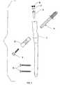
- These componentsconsist of the lag screw assembly 4, the nail body 1, the sleeve 3, the compression screw 6, the end cap 8, snap ring 7, sleeve lock 2 and the cortical screws 5 ( Fig. 1 ).
- the lag screw assembly 4is described in detail in U.S. Patent 6,183,474 B1 , as is compression screw 6.
- the external features of the lag screw assembly 4are indicated in Fig. 4 and include the threads 28, the tang 12, the body 30 and the flats 29 on the body 30.
- the threads 28engage the cancellous bone within the femoral head on the proximal side of the fracture line; the tang body 23' carries the tang 12 which is also located on the proximal side of the fracture line and engages cortical bone as shown in Fig. 2 deployed in the femur.
- the tang 12is fully retracted into the body of the lag screw in its as-delivered state and remains that way until the lag screw assembly is fully positioned within the femoral head.
- the tang 12When deployed in the femoral head, the tang 12 extends through exit hole40' and penetrates the cortical bone, greatly increasing purchase axial fixation and rotational stability of the lag screw assembly.
- the tangis fully reversible if removal of the lag screw is ever required.
- the body 30 of lag screw assembly 4has with two flats 29 180 degrees apart ( Fig.
- the nail body 1is designed for antegrade insertion into the intramedullary canal of the femur. It is anatomically shaped to the axis of the canal and has a mediolateral bend angle H ( Fig. 20 ).
- the proximal outside diameter A of the bodyis greater than the distal outside diameter E due to narrowing of the canal and to allow the lag screw cylindrical transverse clearance bore 33 ( Fig. 20 ) to be large enough to pass the thread 28 of the lag screw assembly 4 and provide a sliding fit to the outside diameter of the sleeve 3 .
- the axis of transverse clearance bore 33is at an angle V with respect to the proximal diametral axis ( Fig. 2 ).
- the nail proximal bore 32, distal bore 31 and distal end bore 24are of circular cross section. Bores 32, 31 and distal end bore 24 are sized to permit a clearance and sliding fit, respectively, with a guide pin (not illustrated) during installation of the nail body 1 into the intramedullary canal.
- the clearance holes 25 of nail body 1pass through the distal outside surface and wall of the nail body 1, into the distal bore 31 and continue on the same axis through the opposite wall and outer diameter. Their diameter is such as to allow passage of the threaded portion of the cortical screw 5. ( Fig.2 ).
- the nail body 1is secured both in axial translation and rotation within the intramedullary canal by cortical screws 5 when they are installed through the lateral cortex, clearance holes 25, and the medial cortex of the femur as illustrated in Fig. 2 .
- the internal threads 37( Fig. 20 ) at the proximal end of the nail body 1 provide for instrument interface and end cap 8 retention.
- the threads 37are used for attachment of a nail removal instrument (not shown).
- the internal threads 37also engage the external threads 15 ( Fig. 16 ) of end cap 8.
- a slot 26( Fig. 19, 22 ) extends through the proximal nail body wall and internal threads 37 breaking into the nail proximal bore 32. Slot 26 is utilized for instrument interface and instrument and end cap 8 anti-rotation.
- the sleeve lock anti-rotation groove 36( Fig. 19, 20 ) is located in the nail proximal bore 32 and 180 degrees around the nail body proximal diameter from slot 26.
- Groove 36extends from the surface of the nail proximal internal bore 32 into the nail proximal wall a given constant depth but not through the wall. It extends axially a given distance, through threads 37 and exits the proximal end of nail body 1 ( Fig. 19, 20 ), Also located in the nail body 1 proximal bore 32, are proximal circumferential groove 34 and distal circumferential groove 35 ( Fig. 20 ).
- the sleeve lock 2( Fig. 1 ), has a basic cylindrical cross section with two integral locking tabs 10 ( Figs. 8, 9,10 ). Each locking tab 10 has a semi-circular cross section, with the radius being the same as that of the cylindrical body section.
- a circumferential groove 14is located in the cylindrical body section and is sized to accept snap ring 7 ( Fig. 1 ).
- An anti-rotation tab 11( Figs.7, 8, 9, 10 ) is an integral part of sleeve lock 2, which protrudes radially and axially from the cylindrical body section and is sized for a sliding fit within nail body 1 anti-rotation groove 36.
- a threaded bore 13( Figs. 7,8 ) extends axially through the cylindrical body section.
- the outside diameter of sleeve lock 2is sized for a sliding fit with proximal bore 32 of nail body 1.
- the snap ring 7( Fig. 1 ), is a toroid of circular cross section with an outside diameter B and inside diameter C ( Figs. 23, 24 ) a gap 41 is provided in the circumference of snap ring 7 to allow radial flexure which either increases or decreases diameters B and C depending on the direction of force.
- the snap ring 7is sized in such a way as to loosely fit within groove 14 of sleeve lock 2 ( Figs. 9, 10 ). When installed into groove 14 snap ring diameter B is larger than the outside diameter of sleeve lock 2, however, if compressed, diameter B becomes equal or less than the outside diameter of sleeve lock 2.
- the end cap 8( Fig. 1 ) is of a cylindrical cross section with a threaded outside diameter 15 and threaded internal bore 16 ( Fig.16 ).
- Two compound anti-rotation groovesrun axially in the outside diameter and are located radially 180 degrees apart.
- the groovesconsist of two sections 20 and 50 ( Figs. 16,17,18 ). Section 20 extends into, but not through the wall of end cap 8 whereas section 50 extends through the wall and breaks into threaded bore 16.
- the outside threads of end cap 8are sized to interface with nail body 1 internal threads 37.
- the nail body 1, sleeve lock 2, snap ring 7 and end cap 8may be pre-assembled by the manufacturer and supplied to surgery as a kit assembly.
- the pre-assemblyconsists of the following steps: the snap ring 7 is expanded and placed into groove 14 of sleeve lock 2.
- the sleeve lock/snap ring assemblyinserts into proximal bore 32 of nail body 1 with locking tabs 10 leading. Since the outside diameter B of snap ring 7 is greater than the nail body 1 proximal bore 32, snap ring 7 will stop when it contacts the proximal end of nail body 1.
- the sleeve lock/snap ring assemblyis then rotated axially to align the sleeve lock anti-rotation tab 11 with nail body anti-rotation groove 36.
- the sleeve lock/snap ring assemblyis inserted further into nail body 1 proximal bore 32 at which time bore 32 acts on snap ring 7 compressing it within groove 14 of sleeve lock 2 allowing the sleeve lock/snap ring assembly to slide in bore 32 and sleeve lock anti-rotation tab 11 to engage nail body 1 sleeve lock anti-rotation groove 36.
- snap ring 7encounters nail body 1 proximal circumferential groove 34 at which time snap ring 7 assumes its original diameter B as it expands into circumferential groove 34, locking or "detenting" the sleeve lock 2 in this position. Additional insertion force causes the snap ring 7 diameter B to interact with bore 32 compressing it back into sleeve lock 2 groove 14, allowing the sleeve lock/snap ring assembly to slide in bore 32 towards nail body 1 distal circumferential groove 35. Upon contacting circumferential groove 35, snap ring 7 will expand into groove 35 locking or "detenting" the sleeve lock 2 in this position.
- end cap 8With the sleeve lock 2 in this position, end cap 8 can be threaded into nail body 1 internal threads 37 with groove section 20 leading. The end cap 8 is installed until its trailing end is as close to flush with the nail body 1 proximal end as practical with the end cap 8 slots 20/50 aligned radially with nail body 1 instrument interface slot 26 and nail body 1 anti-rotation slot 36.
- the sleeve lock 2is now pulled from its "detented” position, with snap ring 7 located at distal circumferential groove 35 ( Fig. 20 ), by use of an instrument (not shown) passed through end cap threaded bore 16 and threaded into sleeve lock 2 threaded bore 13.
- sleeve lock anti-rotation tab 11enters/mates with end cap slots 20/50 and snap ring 7 enters nail body proximal circumferential groove 34 "detenting" sleeve lock 2 into position.
- nail body anti-rotation slot 36, sleeve lock tab 11 and end cap slots 20/50are in a mated condition ( Fig. 6 ). This prevents any relative rotation of nail body 1, sleeve lock 2 and end cap 8 during handling or attachment of the installation instrumentation.
- the nail assemblyis supplied for surgery in this condition. This pre-assembled condition saves surgical time over current intramedullary nail systems that require an end cap and setscrew to be added during surgery.
- Sleeve 3( Fig.1 ) is utilized to secure lag screw assembly 4 into nail body bore 33 after implantation of the lag assembly 4 and nail body 1 in the femur.
- the outside diameter D( Fig.12 ) is sized for a sliding fit in bore 33.
- the sleeve 3has a circular bore 38 and a small length of bore having oppositely disposed flats 17 at the leading end ( Figs.11,12,13 ). These are sized for a sliding fit with the body 30 and flats 29 of lag screw assembly 4 thus allowing axial translation of lag screw assembly 4 but not allowing relative rotation.
- the sleeve 3contains two locking slots 9 ( Figs.
- slots 9are comprised of two features in addition to the opening into the sleeve bore 38. They are the flats 39 and the anti-translation bosses 18. The distance X ( Fig. 14 ) between flats 39 of each slot 9 is sized for a sliding fit in the space Y between locking tabs 10 of sleeve lock 2 ( Fig. 9 ).
- the anti-rotation bosses 18are configured and spaced in such a way as to provide a sliding fit when sleeve 3 and sleeve lock 2 are mated at a relative angle V as shown in Fig. 5 .
- a counterbore 19is provided in the end of sleeve 3 opposite that of the flats 17 and has the configuration as shown in Fig. 13 . It is sized and configured for mating with compression screw 6 as shown in Fig. 2 .
- the nail assemblyconsisting of nail body 1, sleeve lock 2, snap ring 7 and end cap 8 is inserted in an antegrade fashion into the femur.
- an instrumentPrior to insertion, an instrument is attached to the proximal end of the nail assembly.
- the instrument(not shown) utilizes the threaded bore 16 of end cap 8 for attachment and incorporates a protruding feature which mates simultaneously with slot 26 of nail body 1 and slot 50 of end cap 8. This provides angular alignment between the instrument and the nail body 2 and provides anti-rotation of end cap 8 within nail body 1 during attachment/torqueing of the instrument into threaded bore 16 of end cap 8.
- the nail assemblyis inserted into the femur and the lag screw assembly 4 is then inserted through nail body bore 33.
- Instrumentationassures proper insertion depth of lag screw assembly 4 and alignment of the plane of lag screw flats 29 parallel to the nail body proximal bore 32 longitudinal axis.
- sleeve lock 2 and snap ring 7are now translated by instrumentation (not shown), as previously described, such that snap ring 7 moves from nail body proximal circumferential groove 34 to nail body distal circumferential groove 35 and sleeve locking tabs 10 mate into sleeve slots 9 as shown in Fig. 5 .
- sleeve lock 2, snap ring 7 and lag screw 4assembled as shown in Fig. 5 within nail body 1, sleeve 3 is fixed in rotation by interaction of locking tabs 10 and sleeve flats 39 and in translation by interaction of locking tabs 10 with sleeve anti-translation bosses 18.
- lag screw 4is also fixed in rotation by the interaction of sleeve flats 17 and lag screw flats 29 but not fixed in translation.
- the end cap 8remains in position and is utilized to prevent bony ingrowth into nail body internal threads 37, which are used for removal instrument interface, if nail assembly removal is required in the future.
- cortical screws 5can now be used to fix nail body 1 both in translation and rotation within the intramedullary canal.
- the cortical screws 5are placed through the lateral femoral cortex and through clearance holes 25 in the nail body 1, then through the medial femoral cortex ( Fig. 2 ).
- the nail assemblycan be removed by removing cortical screws 5, compression screw 6, retracting tangs 12, as described in detail in U.S. Patent 6,1834,74 B1 , removing end cap 8, releasing sleeve 2 by translating sleeve lock 2 and snap ring 7 to nail body proximal circumferential groove 34, removing sleeve 2 and lag screw 4 and utilizing nail body internal threads 37 to interface a nail body 1 removal instrument (not described) and pull the nail body from the intramedullary canal.
- sleeve lock 2In an alternate kit embodiment ( Fig. 25 ), sleeve lock 2, end cap 8 and snap ring 7 are replaced by sleeve lock assembly 42 ( Fig. 33 ).
- the alternate configuration of sleeve lock 42results in the nail body 1 not requiring sleeve lock anti-rotation groove 36, proximal and distal circumferential grooves 34 and 35. In this embodiment, no implant components are assembled into the nail body 1 prior to its insertion into the femur.
- End cap assembly 42consists of two parts, end cap 43 and bifurcated sleeve lock 44 ( Fig. 33 ).
- the end cap 43contains drive interface 46 ( Fig. 34 ) which provides a means to drive the end cap with an instrument and an external thread 49 ( Fig. 35 ) sized to interface with nail body internal thread 37 ( Fig. 20 ).
- the bifurcated sleeve lock 44incorporates a cylindrical peened interface 48 ( Fig. 36 ) which protrudes through a clearance hole in end cap 43 and into drive interface 46 where it is peened over in such a way as to retain end cap 43 to bifurcated sleeve lock 44 but allow relative rotation of the two parts.
- Locking tabs 47have a semicircular cross section with a radius equal to that of the body of the bifurcated sleeve lock 44 sized to provide a sliding fit in proximal bore 32 of nail body 1 and a width sized to provide a sliding fit between sleeve anti-rotation bosses 18 when the parts are assembled at angle V as shown in Fig. 29 .
- Angle Vcan vary over a range and the fit will still be maintained.
- Distance Z( Fig. 35 ) is such as to provide a sliding fit over dimension X of sleeve 3.
- sleeve lock assembly 42is not pre-assembled into nail body but is instead installed as a last step in the procedure.
- the nail body 1is inserted into the intramedullary canal of the femur, the lag screw 4, sleeve 3, compression screw 6 are installed as well as the cortical screws 5.
- the nail body 1 insertion instrument(not shown) is then removed from the proximal end of nail body 1 and the locking tab 47 ( Fig. 33 ) end of sleeve lock assembly 42 is inserted into the proximal bore 32 of the nail body 1. It must be manipulated to align with sleeve 3 slots 9.
- This alternate embodimentalso allows another method for rotational and translational locking of the nail assembly distally in the intramedullary canal.
- a distal tang 55would be optional ( Fig.25A ). Note that this distal tang 55 would have to be inserted prior to the installation of the sleeve 3, lag screw assembly 4 and compression screw 6.
- the distal end of nail body 1would incorporate an end hole of square cross section 27 ( Fig. 25A ) and four tang exit holes 40 in addition to the cortical screw holes 25.
- Distal bore 31is sized to permit a sliding fit with the tang body 58 ( Fig. 31 ).
- Four tang exit holes 40( Fig. 28 ) are located on a 90 degree radial spacing penetrating from the distal outside diameter E into the distal bore 31, on axes which form an angle J ( Fig. 25A ).
- the clearance holes 25pass through the distal outside surface and wall into the distal bore 31 and continue on the same axis through the opposite wall and outer diameter.
- a frustro-conical feature 59( Fig. 25A ) provides a transition between the circular bore 31 and the square bore 27.
- the square bore 27serves three purposes. It provides clearance through the leading end of the nail body for passage of a guide pin, used during fracture alignment and installation of the of the nail body into the intramedullary canal, it provides a sliding fit for the square forward protrusion 23 ( Fig. 31 ) of tang 3, and it acts as a "vent" hole for any organic material within the bore 31 which is being pushed ahead of the tang during tang installation. It must be noted that the forward most clearance holes 25 also intersect the frustro-conical feature 59 and will act as vents for organic material during tang insertion after the square protrusion 23 has engaged and filled square bore 27.
- the tang 55has four equally sized and radially spaced legs which are preformed to radius R.
- the radius R ( Fig. 32 ) on each leg 21results in a dimension between the trailing ends of opposing legs which is greater than the outside diameter of tang body 58 and the bore diameter 31 of nail body 2.
- the tang body 58is circular in cross section and sized for a sliding fit within nail body bore 31 with a leading edge chamfer 57 which transitions into the leading protrusion 23 which has a square cross section and leading end taper 56.
- Tang body 58contains an internally threaded bore 22 which is the instrument interface for the instrument 51 used to insert and deploy the tang. It must be noted that threaded bore 22 is not needed for tang retraction.
- FIG. 31illustrates the deployed shape of tang 55 which is the shape it assumes after the legs 21 have been forced through the tang exit holes 40 of nail body 1. Insertion/deployment of the tang 55 occurs after insertion of the nail body into the intramedullary canal.
- the insertion/deployment instrument 51( Fig. 27 ) has threads 52 that are mated with tang 55 threaded bore 22.
- the tang 55is now inserted through nail body bore 32 and into nail body bore 31.
- the insertion/deployment instrument 51has a self-centering bushing 53 to help orient the tang 55 for proper insertion.
- the tang leading protrusion 23will slide freely in square bore 27 and the tang legs 21 and the nail body 1 tang exit holes 40 will now be aligned.
- the tang 55continues past tang exit holes 40 and is fully inserted when the tang body leading edge chamfer 57 makes contact with the nail body frustro-conical feature 59 at point K ( Fig. 28 ). In this position, the leading end of tang 55 protrudes through the end of nail body 1 to point N and the trailing end of the tang legs 21 are just past tang exit holes 40.
- the tangis now in position to be deployed. To deploy the tang, an axial force is exerted by the insertion/deployment instrument 51 in the opposite direction as for insertion.
- tang leading square protrusion 23is still engaged by the nail body square bore 27 thus preventing rotation of tang 55 in bore 31 during deployment and preventing unwanted twisting of the tang legs 21.
- the tang 55can be deployed fully or partially and is self-locking in any position due to the almost perpendicular entry angle into the femoral cortex.
- the insertion /deployment instrument 51is The nail body 1 is now fixed axially and rotationally in the intramedullary canal.
- Fig. 26shows the tang 55 in the fully deployed position having translated a distance from point N ( Fig. 28 ) to point M ( Fig. 26 ).
- the tang 55is fully retractable. It is retracted by applying a force on the tang 55 with instrumentation in the opposite direction as deployment until the tang 55 comes to rest at points K and N as shown in Fig. 28 .
- distal fixation of the nail body 1can still be accomplished without use of tang 55.
- the cortical screws 5are placed through the lateral femoral cortex and through clearance holes 25 in the nail body 1, and through the medial femoral cortex ( Fig. 25 ).
- the cortical screwsare not used in conjunction with distal tang fixation and cannot be passed through clearance holes 25 if there is a tang 55 inserted into nail body 1.
- tang 55could have any number of legs 21, square protrusion 23 could take on any keyed polygon shape, sleeve lock 2 could be made with 1 leg 10 and the lag screw may or may not have tangs.
Landscapes
- Health & Medical Sciences (AREA)
- Orthopedic Medicine & Surgery (AREA)
- Surgery (AREA)
- Life Sciences & Earth Sciences (AREA)
- Heart & Thoracic Surgery (AREA)
- Animal Behavior & Ethology (AREA)
- Engineering & Computer Science (AREA)
- Biomedical Technology (AREA)
- Neurology (AREA)
- Medical Informatics (AREA)
- Molecular Biology (AREA)
- Nuclear Medicine, Radiotherapy & Molecular Imaging (AREA)
- General Health & Medical Sciences (AREA)
- Public Health (AREA)
- Veterinary Medicine (AREA)
- Surgical Instruments (AREA)
- Prostheses (AREA)
- Powder Metallurgy (AREA)
Abstract
Description
- The present invention generally relates to an intramedullary system for coupling first and second bone portions across a fracture therebetween and, more specifically, to an intramedullary hip pinning system for rigidly interconnecting a femoral head to the remaining portion of the femur and across a fracture in the area of the femoral neck.
- The intramedullary nail was introduced in the 1930's. This device was inserted into the intramedullary canal of the femur resulting in immediate fixation of fractures, early mobilization of the patient, and a lower morbidity and mortality. A number of nails have been introduced for fracture fixation about the femur in proximal end, including the Jewett Nail and Enders Nail.
- Intramedullary nails were also inserted down the entire length of the femoral canal to provide a basis for the construct. Threaded wires, standard bone screws or cannulated bone screws were then inserted through or along side the proximal nail and into the femoral head to provide fixation and rotational stability. Compression of the proximal bone fragments against each other was not available and in longer nails the distal tip of the nail tends to rotate out of plane which forces the surgeon to locate the distal screw holes using fluoroscopy by a method commonly known as "free-handing".
- In the 1960s, the compression hip screw was introduced, resulting in improved fixation of the proximal femur. A lag screw assembly was inserted into the femoral head, a plate was attached to the lateral femur, and a compression screw joined the two. These implants provided a more rigid structure for the patient and allowed the surgeon to compress the factured fragments against each other thereby decreasing the time to mobility. A number of compression hip screws have been introduced for fracture fixation about the proximal femur.
- During implantation typical compression hip screws require an incision at least equal to the length of plate being used which extends operative time and blood loss. The side plate also creates a protuberance on the lateral side which provides an annoyance to the patient. Compression hip screw systems also fail to provide adequate compression in osteogenic patients because the lag screw threads fail to obtain sufficient purchase due to poor bone stock. Poor purchase is known to contribute to nonunion, malunion and the lag screw assembly eroding through the superior bone of the head of the femur in a condition known as "cut out". Additionally, many patients are dissatisfied with the results of compression hip screw surgery because of the excessive sliding to a medial displacement and shortening position which leads to a change in gait.
- Newer devices and inventions explored additions to the nail and lag screw assembly to improve the fixation and ease or eliminate the need to locate the distal screw holes. These newer devices are commonly classified as "expanding devices" and expand in size, after placement, to fill the intramedullary cavity.
Freedland, U.S. Patent No.s 4,632,101 ,4,862,883 and4,721,103 ,Chemello, U.S. Patent No. 6,077,264 andDavis, U.S. Patent No. 5,057,103 describe a method of fixation which provides points which contact the internal cortical wall. In these patents a mechanism is actuated deploying arms or anchor blades through the cancellous bone to contact the inner cortical wall. These methods are complex, do not deploy through the cortical bone and are difficult to retract should the nail or lag screw assembly require extraction. - Other expanding devices provide surface contact with the internal cortical wall resulting in a wedge effect.
Kurth, U.S. Patent No. 4,590,930 ,Raftopoulos, U.S. Patent No. 4,453,539 andAginski, U.S. Patent No. 4,236,512 among others have described mechanisms which deploy or expand with a molly bolt concept. These methods are complex and difficult to retract should the nail or lag screw assembly requires extraction and do not deploy through the cortical bone. Bolesky, U.S. Patent 4,275,717 , was the first to discuss engagement within the cortical wall. However, Bolesky's invention does not address controlled penetration into the wall and required permanent implantation of the actuation rod. In addition, Bolesky does not address the fundamental problem of the actuation rod's protrusion extramedullarly into the surrounding musculature.- In earlier patents,
U.S. Patent No.s 5,976,139 and6,183,474 B1 , both incorporated herein by reference, Bramlet describes a surgical anchor which has deployable tangs. These tangs are simple in design, internally positioned, yet easily deployed into, and if desired through, the cortical bone providing improved purchase for compression of a fracture; especially in osteogenic bone. These tangs are just as easily retracted should the device require explantation. - In 1988 Lawes, et. al.,
U.S. Patent No. 5,176,681 , disclosed a method of combining desirable aspects of both intramedullary nails and compression hip screws. Lawes described a method for joining the lag screw and nail to resist loosening or moving of the lag screw during the operation. Approximately 10 years ago Howmedica (Rutherford, New Jersey, United States) was the first to produce the "Gamma Nail", named for its similarity in shape to the Greek letter, as an intramedullary hip compression screw device and other designs soon followed. - In 1990 Durham, et. al.,
U.S. Patent No. 5,032,125 , disclosed an intramedullary hip compression screw system which incorporated a sleeve for slidably receiving the lag screw. A set screw was then used to engage the sleeve thereby preventing translation and rotation of the sleeve. This device allowed for reduction of the proximal fragment using the same method as conventional hip screw assemblies. Shortly thereafter Smith & Nephew Richards (Memphis, Tennessee, United States) produced the "Intramedullary Hip Compression Screw". - These intramedullary hip compression screw systems required a few small incisions, allowed capture of the most proximal fragments of the femur, rigid fixation of the most proximal and distal fragments, and a sliding lag screw assembly which allows reduction of the fragments as the patient ambulates or begins to bear weight on the fractured limb. These nails are typically held in place on the distal end through interference forces with the intramedullary canal and through the use of locking screws.
- The typical intramedullary hip compression screw's shape accommodates the relative shape of the greater trochanter and femoral shaft, neck and head fragments. Therefore, the shape of the hip is preserved. Indications for use of a compression hip screw are expanded because fractures to the subtrochanteric region of the proximal femur, as well as reverse obliquity fractures can be treated more efficiently. Additionally, the bulk of an intramedullary hip screw blocks excessive sliding of the proximal fragment.
- Current intramedullary compression hip screw systems continue to suffer from some of the same problems exhibited in those of its predecessors. Osteogenic bone still provides a poor medium for purchase of the lag screw assembly thread inhibiting adequate compression and rotational stability. Longer nails continue to see the distal tip of the nail rotating out of plane forcing the surgeon to locate the distal screw holes by the free-hand method. The free-handing technique leads to an increased surgical time and exposes the surgeon and patient to increased radiation dosages.
- Current intramedullary compression hip screw systems also provide new limitations that hamper their effectiveness. One such limitation is evident in both Lawes' and Durham's designs. These designs require the use of a set screw to prevent rotation of the lag screw; the set screw in the Lawes patent interacts directly with the lag screw, while Durham's is indirect with the lag screw. To ensure proper mating takes place the Smith & Nephew Richards' systems provides a torque wrench, while Howmedica's system requires tightening of the set screw to full engagement and then backing it off. Over time, loss of calibration of the torque wrench and improper engagement by the surgeon user could lead to an unsatisfactory engagement and decreased usefulness.
- Clearly a need exists for a system that is superior to the conventional compression hip screws while minimizing the surgical insult to the human body.
EP-A-0441577 discloses an intramedullary hip screw including an intramedullary rod, a lag screw and a sleeve for slidably receiving the lag screw. The sleeve is received in a passage in the intramedullary rod having an axis which is oblique to the longitudinal axis of the intramedullary rod such that the axis of the sleeve is directed toward the head of the femur.WO-A-0076414 - Therefore, it is an object of this invention to teach a simple, effective and controllable fixation device which allows greater purchase of the lag screw assembly within the femoral head resulting in improved compression across the fracture line.
- It is another object of this invention to teach a system with rotational stability both in the femoral head and in the femoral shaft, and that offers to minimize, if not eliminate the need for additional distal incisions to locate and place locking screws.
- It is yet another objective of this invention to teach an intramedullary hip nail system that provides for a more positive, and more repeatable engagement mechanism for allowing the lag screw to slide during fracture reduction and healing.
- It is a further objective of this invention to teach a system designed to allow the surgeon a choice of penetration distance within the femoral head and femoral shaft fixation based upon the injuries presented and the desired level of treatment.
- It is a still further objective of this invention to teach a system that allows explantation to occur as easily as implantation.
- The invention comprises an intramedullary nail system kit as defined in the appended claims.
- An intramedullary nail system for coupling first and second bone portions across a fracture therebetween may be provided as a kit of several assembled subassemblies. The subassemblies of the intramedullary nail system according to the invention are combined for installation within the medullary canal of a fractured bone, such as a femur.
- In one embodiment of the present invention, the intramedullary nail system includes an intramedullary nail body having an internally threaded trailing end and a leading end with portals which allow passage of cortical screws. The nail body has a transverse clearance bore near the trailing end in communication with an axial bore for receiving a lag screw assembly. The lag screw assembly has a leading end with an externally threaded portion with portals which allow passage of anchoring tangs and internally deployable and retractable anchoring tangs. The lag screw assembly has internal threads on the trailing end. A slotted sleeve slidably passes through a transverse clearance bore of the intramedullary nail and freely telescopes over the lag screw assembly while preventing rotation of lag screw assembly, but allowing axial translation of the lag screw. A compression screw has a shoulder contacting the trailing end of the slotted sleeve and engages the internal threads of the lag screw assembly trailing end providing axial translation of the lag screw assembly within the sleeve. A sleeve lock passes through the axial bore of the intramedullary nail and along the slotted sleeve through its slot(s) thereby preventing rotation and axial translation of the sleeve, but allowing axial translation of the lag screw assembly.
- An end cap assembly with external threads engages the internal threads of the trailing end of the intramedullary nail.
- A preferred embodiment combines the intramedullary nail, the sleeve lock and the end cap assembly into an intramedullary nail assembly. When presented as such, the surgeon or surgical assistant will not have to enjoin these items during the surgical procedure.
- The end cap assembly preferably contains a patch of ultra-high molecular weight poly-ethylene (UHMWPE) within the threads. This provides constant positive engagement between the end cap external threads and the intramedullary nail internal threads.
- With the intramedullary nail placed into position within the intramedullary canal the lag screw assembly is then placed into position in a manner consistent with common technique. The unique tang assembly is actuated and the tangs are deployed to any desired position thereby achieving the desired level of fixation based upon the quality of the bone.
- The lag screw assembly preferably contains a permanently placed anchoring tang assembly stored in a retracted position within the leading end. The tangs are deployed or retracted from the trailing end of the lag screw assembly.
- The slotted sleeve is coaxially inserted over the lag screw assembly's trailing end and through the intramedullary nail. The slotted sleeve is aligned to accept the sleeve lock.
- The sleeve lock is actuated via a mechanism in the intramedullary nail insertion instrument. The sleeve lock moves from its primary position to its final position. In its final position the sleeve lock passes through the slotted sleeve slots preventing rotation and axial translation of the slotted sleeve.
- The compression screw passes through the sleeve and engages the lag screw assembly. As the compression screw is tightened the lag screw assembly and associated first bone portion are pulled against the intramedullary nail and second bone portion resulting in compressive forces being applied across the fracture.
- The compression screw preferably contains a patch of ultra-high molecular weight poly-ethylene (UHMWPE) within the threads. This provides constant positive engagement between the compression screw external threads and the lag screw assembly internal threads.
- The cortical screws are then placed into position through the bone and through the intramedullary nail in a manner consistent with common technique.
- In another embodiment of the present invention the intramedullary nail system includes a intramedullary nail with portals at the leading end which allow passage of cortical screws and/or anchoring tangs. When the intramedullary nail is placed into position the anchoring tang assembly is actuated to deploy the tangs out from their stowed position into the cortical bone. The tangs are deployed to any desired position thereby achieving a desired fixation and rotation prevention based upon the quality of the bone. Should the system require additional load carrying capability, cortical screws may be placed to enjoin the intramedullary nail with the surrounding cortical bone.
- The intramedullary nail of this alternate embodiment is preferably cannulated to allow passage of one or more anchoring tang assemblies. These anchoring tang assemblies are inserted from the trailing end towards the leading end and the tangs deployed by means of an actuator driver. An alternate embodiment of the intramedullary nail has a retracted anchoring tang assembly, which is permanently placed within the leading end of the intramedullary nail and is deployed or retracted by means of an actuator driver from the trailing end of the intramedullary nail.
- The anchoring tang assembly contains arcurate shaped tangs that are permanently attached to the assembly's main body. These tangs are initially formed into a prescribed position for storage. As the assembly is actuated, and the tangs deploy, the tangs are formed into their final shape through interaction with the portal of either the intramedullary nail or the lag screw assembly.
- The lag screw assembly preferably contains a permanently placed anchoring tang assembly stored in a retracted position within the leading end. The tangs are deployed or retracted from the trailing end of the lag screw assembly.
- The anchoring tang assembly within the lag screw is similar in design to that within the intramedullary nail in that it contains arcurate shaped tangs that are permanently attached to the assembly's tang body. These tangs are initially formed into a prescribed position for storage. As the assembly is actuated, and the tangs deploy, the tangs are formed into their final shape through interaction with the portal of either the intramedullary nail or the lag screw assembly.
- The end cap preferably contains a patch of ultra-high molecular weight poly-ethylene (UHMWPE) within the threads. This provides constant positive engagement between the end cap external threads and the intramedullary nail internal threads. In its final position the end cap locks the sleeve and inhibits the sleeve from sliding or rotating out of a prescribed position.
- The intramedullary nail system may be supplied as a kit with subassemblies to be combined into the complete system during the surgical procedure.
- FIG. 1,
- is a longitudinal view of the preferred embodiment Intramedullary Nail System in an exploded state;
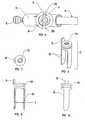
- FIG. 2,
- is a view, partially in longitudinal cross section, of the Intramedullary Nail System placed in the intramedullary canal of a fractured bone using cortical screws as a method of fixation;
- FIG. 3,
- is an enlarged, cross section view of the proximal portion of the Intramedullary Nail System in
FIG. 2 ; - FIG. 4,
- is an enlarged view of the proximal portion of the Intramedullary Nail System of
FIG. 2 ; - FIG. 5,
- is an enlarged view of the proximal portion of the Intramedullary Nail System of
FIG. 3 ; - FIG. 6,
- is a top view of the Intramedullary Nail System of
FIG. 2 ; - FIG. 7,
- is a top view of
FIG. 8 ; - FIG. 8,
- is an isometric view of the Sleeve Lock;
- FIG. 9,
- is a front view of
FIG. 8 ; - FIG. 10,
- is a side view of
FIG. 8 ; - FIG. 11,
- is an isometric view of the Slotted Sleeve;
- FIG. 12,
- is a top view of
FIG. 11 ; - FIG. 13,
- is a section view of
FIG. 11 ; - FIG. 14,
- is a front view of
FIG. 11 ; - FIG. 15,
- is a side view of
FIG. 11 ; - FIG. 16,
- is an isometric view of the End Cap Assembly;
- FIG. 17,
- is a top view of
FIG. 16 ; - FIG. 18,
- is a side view of
FIG. 16 ; - FIG. 19,
- is a top view of
FIG. 21 ; - FIG. 20,
- is a section view of
FIG. 21 ; - FIG. 21,
- is a front view of the Intramedullary Nail;
- FIG. 22,
- is an enlarged, partial side view of
FIG. 21 ; - FIG. 23,
- is an isometric view of the Snap Ring;
- FIG. 24,
- is a top view of
FIG. 22 ; - FIG. 25,
- is a view, partially in longitudinal cross section, of the alternate embodiment Intramedullary Nail System placed in the intramedullary canal of a fractured bone using cortical screws as a method of fixation;
- FIG. 25A,
- is an enlarged view of the distal portion, of the alternate embodiment Intramedullary Nail System in
FIG. 25 using the talon as a method of fixation; - FIG. 26,
- is an enlarged view of the distal portion, of the alternate embodiment Intramedullary Nail System in
FIG. 25 during Tang Assembly deployment; - FIG. 27,
- is an enlarged, partial view of the Tang Actuator Assembly of
FIG. 26 ; - FIG. 28,
- is an enlarged view of the stowed Tang Assembly from
FIG. 25A ; - FIG. 29,
- is an enlarged proximal view of the alternate embodiment Intramedullary Nail System of
FIG. 25 ; - FIG. 30,
- is an enlargement of the Tang Assembly in
FIG. 32 ; - FIG. 31,
- is a front view of the deployed Tang Assembly;
- FIG. 32,
- is a front view of the stowed Tang Assembly;
- FIG. 33,
- is an isometric view of the alternate embodiment Sleeve Lock;
- FIG. 34,
- is a top view of
FIG. 33 ; - FIG. 35,
- is a front view of
FIG. 33 ; and - FIG. 36,
- is a cross section view of
FIG. 33 - The individual components of the assembly, as illustrated in
Fig.1 , are constructed of implantable grade stainless steel alloys in the preferred embodiment but could also be constructed of implantable grade titanium alloys or polymeric materials such as nylon, carbon fibers and thermoplastics, as well. These components consist of thelag screw assembly 4, the nail body 1, thesleeve 3, thecompression screw 6, theend cap 8,snap ring 7,sleeve lock 2 and the cortical screws 5 (Fig. 1 ). - The
lag screw assembly 4 is described in detail inU.S. Patent 6,183,474 B1 , as iscompression screw 6. The external features of thelag screw assembly 4 are indicated inFig. 4 and include thethreads 28, thetang 12, thebody 30 and theflats 29 on thebody 30. Thethreads 28 engage the cancellous bone within the femoral head on the proximal side of the fracture line; the tang body 23' carries thetang 12 which is also located on the proximal side of the fracture line and engages cortical bone as shown inFig. 2 deployed in the femur. However, thetang 12 is fully retracted into the body of the lag screw in its as-delivered state and remains that way until the lag screw assembly is fully positioned within the femoral head. When deployed in the femoral head, thetang 12 extends through exit hole40' and penetrates the cortical bone, greatly increasing purchase axial fixation and rotational stability of the lag screw assembly. The tang is fully reversible if removal of the lag screw is ever required. Thebody 30 oflag screw assembly 4 has with twoflats 29 180 degrees apart (Fig. 4 ) which interfaces withbore 38 and end configuration flats 17 (Figs.11,12,13 ) of thesleeve 3 in such a way as to allow axial translation or slide of the lag screw while preventing rotation relative to thesleeve 3. This sliding prevents penetration of the femoral head by the proximal end of the lag screw as the fracture compresses from patient load bearing. - The nail body 1 is designed for antegrade insertion into the intramedullary canal of the femur. It is anatomically shaped to the axis of the canal and has a mediolateral bend angle H (
Fig. 20 ). The proximal outside diameter A of the body is greater than the distal outside diameter E due to narrowing of the canal and to allow the lag screw cylindrical transverse clearance bore 33 (Fig. 20 ) to be large enough to pass thethread 28 of thelag screw assembly 4 and provide a sliding fit to the outside diameter of thesleeve 3 . The axis of transverse clearance bore 33 is at an angle V with respect to the proximal diametral axis (Fig. 2 ). This angle V allows proper positioning oflag screw assembly 4 within the femoral head. The nail proximal bore 32,distal bore 31 and distal end bore 24 are of circular cross section.Bores distal bore 31 and continue on the same axis through the opposite wall and outer diameter. Their diameter is such as to allow passage of the threaded portion of thecortical screw 5. (Fig.2 ). The nail body 1 is secured both in axial translation and rotation within the intramedullary canal bycortical screws 5 when they are installed through the lateral cortex, clearance holes 25, and the medial cortex of the femur as illustrated inFig. 2 . - The internal threads 37 (
Fig. 20 ) at the proximal end of the nail body 1 provide for instrument interface andend cap 8 retention. Thethreads 37 are used for attachment of a nail removal instrument (not shown). Theinternal threads 37 also engage the external threads 15 (Fig. 16 ) ofend cap 8. A slot 26 (Fig. 19, 22 ) extends through the proximal nail body wall andinternal threads 37 breaking into the nail proximal bore 32.Slot 26 is utilized for instrument interface and instrument andend cap 8 anti-rotation. The sleeve lock anti-rotation groove 36 (Fig. 19, 20 ) is located in the nail proximal bore 32 and 180 degrees around the nail body proximal diameter fromslot 26.Groove 36 extends from the surface of the nail proximalinternal bore 32 into the nail proximal wall a given constant depth but not through the wall. It extends axially a given distance, throughthreads 37 and exits the proximal end of nail body 1 (Fig. 19, 20 ), Also located in the nail body 1 proximal bore 32, are proximalcircumferential groove 34 and distal circumferential groove 35 (Fig. 20 ). - The sleeve lock 2 (
Fig. 1 ), has a basic cylindrical cross section with two integral locking tabs 10 (Figs. 8, 9,10 ). Each lockingtab 10 has a semi-circular cross section, with the radius being the same as that of the cylindrical body section. Acircumferential groove 14 is located in the cylindrical body section and is sized to accept snap ring 7 (Fig. 1 ). An anti-rotation tab 11 (Figs.7, 8, 9, 10 ) is an integral part ofsleeve lock 2, which protrudes radially and axially from the cylindrical body section and is sized for a sliding fit within nail body 1anti-rotation groove 36. A threaded bore 13 (Figs. 7,8 ) extends axially through the cylindrical body section. The outside diameter ofsleeve lock 2 is sized for a sliding fit withproximal bore 32 of nail body 1. - The snap ring 7 (
Fig. 1 ), is a toroid of circular cross section with an outside diameter B and inside diameter C (Figs. 23, 24 ) agap 41 is provided in the circumference ofsnap ring 7 to allow radial flexure which either increases or decreases diameters B and C depending on the direction of force. Thesnap ring 7 is sized in such a way as to loosely fit withingroove 14 of sleeve lock 2 (Figs. 9, 10 ). When installed intogroove 14 snap ring diameter B is larger than the outside diameter ofsleeve lock 2, however, if compressed, diameter B becomes equal or less than the outside diameter ofsleeve lock 2. - The end cap 8 (
Fig. 1 ) is of a cylindrical cross section with a threaded outsidediameter 15 and threaded internal bore 16 (Fig.16 ). Two compound anti-rotation grooves run axially in the outside diameter and are located radially 180 degrees apart. The grooves consist of twosections 20 and 50 (Figs. 16,17,18 ).Section 20 extends into, but not through the wall ofend cap 8 whereassection 50 extends through the wall and breaks into threadedbore 16. The outside threads ofend cap 8 are sized to interface with nail body 1internal threads 37. - The nail body 1,
sleeve lock 2,snap ring 7 andend cap 8 may be pre-assembled by the manufacturer and supplied to surgery as a kit assembly. The pre-assembly consists of the following steps: thesnap ring 7 is expanded and placed intogroove 14 ofsleeve lock 2. The sleeve lock/snap ring assembly inserts intoproximal bore 32 of nail body 1 with lockingtabs 10 leading. Since the outside diameter B ofsnap ring 7 is greater than the nail body 1 proximal bore 32,snap ring 7 will stop when it contacts the proximal end of nail body 1. The sleeve lock/snap ring assembly is then rotated axially to align the sleevelock anti-rotation tab 11 with nailbody anti-rotation groove 36. The sleeve lock/snap ring assembly is inserted further into nail body 1 proximal bore 32 at which time bore 32 acts onsnap ring 7 compressing it withingroove 14 ofsleeve lock 2 allowing the sleeve lock/snap ring assembly to slide inbore 32 and sleevelock anti-rotation tab 11 to engage nail body 1 sleevelock anti-rotation groove 36. As insertion continues,snap ring 7 encounters nail body 1 proximalcircumferential groove 34 at whichtime snap ring 7 assumes its original diameter B as it expands intocircumferential groove 34, locking or "detenting" thesleeve lock 2 in this position. Additional insertion force causes thesnap ring 7 diameter B to interact withbore 32 compressing it back intosleeve lock 2groove 14, allowing the sleeve lock/snap ring assembly to slide inbore 32 towards nail body 1 distalcircumferential groove 35. Upon contactingcircumferential groove 35,snap ring 7 will expand intogroove 35 locking or "detenting" thesleeve lock 2 in this position. With thesleeve lock 2 in this position,end cap 8 can be threaded into nail body 1internal threads 37 withgroove section 20 leading. Theend cap 8 is installed until its trailing end is as close to flush with the nail body 1 proximal end as practical with theend cap 8slots 20/50 aligned radially with nail body 1instrument interface slot 26 and nail body 1anti-rotation slot 36. Thesleeve lock 2, is now pulled from its "detented" position, withsnap ring 7 located at distal circumferential groove 35 (Fig. 20 ), by use of an instrument (not shown) passed through end cap threaded bore 16 and threaded intosleeve lock 2 threaded bore 13. The force causessnap ring 7 to be compressed intosleeve lock 2groove 14 which allowssleeve lock 2 to translate towards proximalcircumferential groove 34. Assleeve lock 2 translates,anti-rotation tab 11 slides in nail body 1 sleevelock anti-rotation groove 36 thus preventing relative rotation betweensleeve lock 2 and the nail body 1. Sinceend cap 8slots 20/50 were aligned with nail body 1 sleevelock anti-rotation slot 36, sleeve lock anti-rotation tab 11is aligned withend cap 8slots 20/50. Assleeve lock 2 continues to translate towardsend cap 8, sleevelock anti-rotation tab 11 enters/mates withend cap slots 20/50 andsnap ring 7 enters nail body proximalcircumferential groove 34 "detenting"sleeve lock 2 into position. Withsleeve lock 2 in this position, nailbody anti-rotation slot 36,sleeve lock tab 11 andend cap slots 20/50 are in a mated condition (Fig. 6 ). This prevents any relative rotation of nail body 1,sleeve lock 2 andend cap 8 during handling or attachment of the installation instrumentation. The nail assembly is supplied for surgery in this condition. This pre-assembled condition saves surgical time over current intramedullary nail systems that require an end cap and setscrew to be added during surgery. - Sleeve 3 (
Fig.1 ) is utilized to securelag screw assembly 4 into nail body bore 33 after implantation of thelag assembly 4 and nail body 1 in the femur. The outside diameter D (Fig.12 ) is sized for a sliding fit inbore 33. Thesleeve 3 has acircular bore 38 and a small length of bore having oppositely disposedflats 17 at the leading end (Figs.11,12,13 ). These are sized for a sliding fit with thebody 30 andflats 29 oflag screw assembly 4 thus allowing axial translation oflag screw assembly 4 but not allowing relative rotation. Thesleeve 3 contains two locking slots 9 (Figs. 11, 14 ), which continue throughsleeve 3 wall thickness and are located opposite each other (180 degrees radially) on thesleeve 3 body. These slots 9 are comprised of two features in addition to the opening into the sleeve bore 38. They are theflats 39 and theanti-translation bosses 18. The distance X (Fig. 14 ) betweenflats 39 of each slot 9 is sized for a sliding fit in the space Y between lockingtabs 10 of sleeve lock 2 (Fig. 9 ). Theanti-rotation bosses 18 are configured and spaced in such a way as to provide a sliding fit whensleeve 3 andsleeve lock 2 are mated at a relative angle V as shown inFig. 5 . The locking slots 9 configuration still functions when angle V is varied over a small range. Acounterbore 19 is provided in the end ofsleeve 3 opposite that of theflats 17 and has the configuration as shown inFig. 13 . It is sized and configured for mating withcompression screw 6 as shown inFig. 2 . - The nail assembly consisting of nail body 1,
sleeve lock 2,snap ring 7 andend cap 8 is inserted in an antegrade fashion into the femur. Prior to insertion, an instrument is attached to the proximal end of the nail assembly. The instrument (not shown) utilizes the threaded bore 16 ofend cap 8 for attachment and incorporates a protruding feature which mates simultaneously withslot 26 of nail body 1 and slot 50 ofend cap 8. This provides angular alignment between the instrument and thenail body 2 and provides anti-rotation ofend cap 8 within nail body 1 during attachment/torqueing of the instrument into threaded bore 16 ofend cap 8. The nail assembly is inserted into the femur and thelag screw assembly 4 is then inserted through nail body bore 33. Instrumentation assures proper insertion depth oflag screw assembly 4 and alignment of the plane oflag screw flats 29 parallel to the nail body proximal bore 32 longitudinal axis. After thelag screw 4 is implanted in its proper position within the femur, its trailing end protrudes partially or fully through nail body 1 bore 33. The leading end ofsleeve 3 containingflats 17 is inserted intobore 33 and thebore 38 ofsleeve 3 aligned, with the aid of instrumentation (not shown) with the similarly shapedlag screw body 30. Thesleeve 3 is inserted further intobore 33 thus mating withlag screw 4. Since, as described previously,sleeve flats 17 interact withlag screw flats 29 preventing relative rotation betweenlag screw 4 andsleeve 3 and the plane oflag screw flats 29 are already aligned parallel to nail proximal bore 32 longitudinal axis the plane of thesleeve flats 39 are now also aligned parallel with the nail proximal bore 32 longitudinal axis. Instrumentation (not shown) has also located the centerline ofsleeve 3 slots 9 coincident to the longitudinal axis of nail body proximal bore 32 and therefore also coincident withsleeve locking tab 10 longitudinal axis. Thesleeve lock 2,snap ring 7,sleeve 3 and lagscrew 4 are now in the relative positions as shown inFig. 4 . - The
sleeve lock 2 andsnap ring 7 are now translated by instrumentation (not shown), as previously described, such thatsnap ring 7 moves from nail body proximalcircumferential groove 34 to nail body distalcircumferential groove 35 andsleeve locking tabs 10 mate into sleeve slots 9 as shown inFig. 5 . Withsleeve 3,sleeve lock 2,snap ring 7 and lagscrew 4 assembled as shown inFig. 5 within nail body 1,sleeve 3 is fixed in rotation by interaction of lockingtabs 10 andsleeve flats 39 and in translation by interaction of lockingtabs 10 withsleeve anti-translation bosses 18. Sincesleeve 3 is now fixed in rotation,lag screw 4 is also fixed in rotation by the interaction ofsleeve flats 17 andlag screw flats 29 but not fixed in translation. Theend cap 8 remains in position and is utilized to prevent bony ingrowth into nail bodyinternal threads 37, which are used for removal instrument interface, if nail assembly removal is required in the future. - With
sleeve 3 and lagscrew 4 fixed in rotation, tangs 12 oflag screw 4 can be deployed as described inU.S. Patent 6,183,474 B1 . Aftertang 12 deployment,compression screw 6 is inserted throughbore 38 ofsleeve 3 mating its threaded end with internal threads withinlag screw 4 and its head withsleeve counterbore 19. Ascompression screw 6 is tightened, its headcontacts sleeve counterbore 19, and sincesleeve 3 is fixed in translation by lockingtabs 10,lag screw 4 is drawn toward nail body 1 thereby compressing the fracture. - One or two
cortical screws 5 can now be used to fix nail body 1 both in translation and rotation within the intramedullary canal. Thecortical screws 5 are placed through the lateral femoral cortex and throughclearance holes 25 in the nail body 1, then through the medial femoral cortex (Fig. 2 ). - The nail assembly can be removed by removing
cortical screws 5,compression screw 6, retractingtangs 12, as described in detail inU.S. Patent 6,1834,74 B1end cap 8, releasingsleeve 2 by translatingsleeve lock 2 andsnap ring 7 to nail body proximalcircumferential groove 34, removingsleeve 2 and lagscrew 4 and utilizing nail bodyinternal threads 37 to interface a nail body 1 removal instrument (not described) and pull the nail body from the intramedullary canal. - In an alternate kit embodiment (
Fig. 25 ),sleeve lock 2,end cap 8 andsnap ring 7 are replaced by sleeve lock assembly 42 (Fig. 33 ). The alternate configuration ofsleeve lock 42 results in the nail body 1 not requiring sleevelock anti-rotation groove 36, proximal and distalcircumferential grooves End cap assembly 42 consists of two parts,end cap 43 and bifurcated sleeve lock 44 (Fig. 33 ). Theend cap 43 contains drive interface 46 (Fig. 34 ) which provides a means to drive the end cap with an instrument and an external thread 49 (Fig. 35 ) sized to interface with nail body internal thread 37 (Fig. 20 ). Thebifurcated sleeve lock 44 incorporates a cylindrical peened interface 48 (Fig. 36 ) which protrudes through a clearance hole inend cap 43 and intodrive interface 46 where it is peened over in such a way as to retainend cap 43 tobifurcated sleeve lock 44 but allow relative rotation of the two parts. Lockingtabs 47 have a semicircular cross section with a radius equal to that of the body of thebifurcated sleeve lock 44 sized to provide a sliding fit inproximal bore 32 of nail body 1 and a width sized to provide a sliding fit between sleeveanti-rotation bosses 18 when the parts are assembled at angle V as shown inFig. 29 . Angle V can vary over a range and the fit will still be maintained. Distance Z (Fig. 35 ) is such as to provide a sliding fit over dimension X ofsleeve 3.- Unlike the preferred embodiment,
sleeve lock assembly 42 is not pre-assembled into nail body but is instead installed as a last step in the procedure. The nail body 1 is inserted into the intramedullary canal of the femur, thelag screw 4,sleeve 3,compression screw 6 are installed as well as the cortical screws 5. The nail body 1 insertion instrument (not shown) is then removed from the proximal end of nail body 1 and the locking tab 47 (Fig. 33 ) end ofsleeve lock assembly 42 is inserted into the proximal bore 32 of the nail body 1. It must be manipulated to align withsleeve 3 slots 9. Note that this manipulation could be eased through the addition of a keying feature between thebifurcated sleeve lock 44 and the nail proximal bore 32. Once aligned, lockingtabs 47 will enter and mate with sleeve slots 9 allowing the sleeve lock assembly to translate far enough forthreads 49 ofend cap 43 to mate with nail bodyinternal threads 37. Since the peened interface betweenend cap 43 andbifurcated sleeve lock 44 allow relative rotation, driveinterface 46 can be used to fully engagethreads - This alternate embodiment also allows another method for rotational and translational locking of the nail assembly distally in the intramedullary canal. Instead of
cortical screws 5, use of adistal tang 55 would be optional (Fig.25A ). Note that thisdistal tang 55 would have to be inserted prior to the installation of thesleeve 3,lag screw assembly 4 andcompression screw 6. - In this embodiment, the distal end of nail body 1 would incorporate an end hole of square cross section 27 (
Fig. 25A ) and four tang exit holes 40 in addition to the cortical screw holes 25. Distal bore 31 is sized to permit a sliding fit with the tang body 58 (Fig. 31 ). Four tang exit holes 40 (Fig. 28 ) are located on a 90 degree radial spacing penetrating from the distal outside diameter E into thedistal bore 31, on axes which form an angle J (Fig. 25A ). The clearance holes 25 pass through the distal outside surface and wall into thedistal bore 31 and continue on the same axis through the opposite wall and outer diameter. Their diameter is such as to allow passage of the threaded portion of the cortical screw 5 (FIG.1 ). A frustro-conical feature 59 (Fig. 25A ) provides a transition between thecircular bore 31 and the square bore 27. The square bore 27 serves three purposes. It provides clearance through the leading end of the nail body for passage of a guide pin, used during fracture alignment and installation of the of the nail body into the intramedullary canal, it provides a sliding fit for the square forward protrusion 23 (Fig. 31 ) oftang 3, and it acts as a "vent" hole for any organic material within thebore 31 which is being pushed ahead of the tang during tang installation. It must be noted that the forwardmost clearance holes 25 also intersect the frustro-conical feature 59 and will act as vents for organic material during tang insertion after thesquare protrusion 23 has engaged and filled square bore 27. - The
tang 55 has four equally sized and radially spaced legs which are preformed to radius R. The radius R (Fig. 32 ) on eachleg 21 results in a dimension between the trailing ends of opposing legs which is greater than the outside diameter oftang body 58 and thebore diameter 31 ofnail body 2. Thetang body 58 is circular in cross section and sized for a sliding fit within nail body bore 31 with aleading edge chamfer 57 which transitions into the leadingprotrusion 23 which has a square cross section andleading end taper 56.Tang body 58 contains an internally threaded bore 22 which is the instrument interface for theinstrument 51 used to insert and deploy the tang. It must be noted that threaded bore 22 is not needed for tang retraction.Fig. 31 illustrates the deployed shape oftang 55 which is the shape it assumes after thelegs 21 have been forced through the tang exit holes 40 of nail body 1. Insertion/deployment of thetang 55 occurs after insertion of the nail body into the intramedullary canal. The insertion/deployment instrument 51 (Fig. 27 ) hasthreads 52 that are mated withtang 55 threaded bore 22. Thetang 55 is now inserted through nail body bore 32 and into nail body bore 31. The insertion/deployment instrument 51 has a self-centeringbushing 53 to help orient thetang 55 for proper insertion. Since the distance between opposingtang legs 21 is greater than thebore diameter 31 due to radius R, the interference withbore 31 forces thelegs 21 inward in an elastic manner and insertion continues with some resistance. As the tang travels down bore 31, any organic material which has accumulated inbore 31 is pushed ahead and forced out through square bore 27 of nail body 1 and through cortical screw clearance holes 25. Further insertion causes thetang 55 leadingsquare taper 56 to contact the square bore 27 of the nail body 1. Since both cross sections are square, no engagement will occur until they are radially aligned which may or may not occur without some slight rotation of thetang 55 using the insertion/deployment instrument 51 (Fig. 27 ). After alignment occurs and by virtue of this alignment, thetang leading protrusion 23 will slide freely in square bore 27 and thetang legs 21 and the nail body 1 tang exit holes 40 will now be aligned. Thetang 55 continues past tang exit holes 40 and is fully inserted when the tang body leadingedge chamfer 57 makes contact with the nail body frustro-conical feature 59 at point K (Fig. 28 ). In this position, the leading end oftang 55 protrudes through the end of nail body 1 to point N and the trailing end of thetang legs 21 are just past tang exit holes 40. The tang is now in position to be deployed. To deploy the tang, an axial force is exerted by the insertion/deployment instrument 51 in the opposite direction as for insertion. This causes thetang 55 to translate back up bore 31 and the sharp ends oftang legs 21 to encounter tang exit holes 40. Since thetang legs 21 were elastically compressed inward bybore 31 they will now spring outward forcing the sharp end oftang legs 21 into tang exit holes 40. Further translation of thetang 55 forces the tang legs through the tang exit holes 40. Due to the diameter and angle of the tang exit holes 40, thetang legs 21 are formed in such a manner as to emerge almost perpendicular to the femoral cortex (Fig. 25A ). Continued translation of thetang 55 causes thetang legs 21 to penetrate the femoral cortex. During this time, tang leadingsquare protrusion 23 is still engaged by the nail body square bore 27 thus preventing rotation oftang 55 inbore 31 during deployment and preventing unwanted twisting of thetang legs 21. Thetang 55 can be deployed fully or partially and is self-locking in any position due to the almost perpendicular entry angle into the femoral cortex. After deployment, the insertion /deployment instrument 51 is The nail body 1 is now fixed axially and rotationally in the intramedullary canal.Fig. 26 shows thetang 55 in the fully deployed position having translated a distance from point N (Fig. 28 ) to point M (Fig. 26 ). Thetang 55 is fully retractable. It is retracted by applying a force on thetang 55 with instrumentation in the opposite direction as deployment until thetang 55 comes to rest at points K and N as shown inFig. 28 . - Note that at the surgeon's discretion, distal fixation of the nail body 1 can still be accomplished without use of
tang 55. This is accomplished by using the cortical screws 5 (Fig. 1 ) as described in the preferred embodiment. Thecortical screws 5 are placed through the lateral femoral cortex and throughclearance holes 25 in the nail body 1, and through the medial femoral cortex (Fig. 25 ). The cortical screws are not used in conjunction with distal tang fixation and cannot be passed throughclearance holes 25 if there is atang 55 inserted into nail body 1. - It should be noted that this description is directed at only one possible alternate embodiment and that many others are possible ending with the same results without departing from the scope of the invention as defined in the claims. As examples,
tang 55 could have any number oflegs 21,square protrusion 23 could take on any keyed polygon shape,sleeve lock 2 could be made with 1leg 10 and the lag screw may or may not have tangs.
Claims (4)
- An intramedullary nail system kit for applying Compressive force across a fracture, said kit comprising an intramedullary nail (1) having a leading end, a trailing end, an axial bore (31,32), a transverse clearance bore (33) in said trailing end intersecting said axial bore, and a plurality of portals (25) through said leading end, a plurality of anchors (5) adapted to extend through said portals, a lag screw (4) with external screw threads (28) en one end and internal screw threads on the other end, a sleeve (3) having a bore (38) with an internal diameter larger than said other end of said lag screw and an external diameter to slidably extend through said transverse clearance bore (33),characterized in that said sleeve (3) having at least one transverse slot (9) exposing said sleeve bore (38), a sleeve lock (2) sized to slide in said axial bore (32) at said trailing end, said sleeve lock (2) having at least one locking tab disposed in said axial bore (32) extending toward said transverse clearance bore (33), and a compression screw (6) with complementary threads for the internal threads of said lag screw, said compression screw having a shoulder for engaging said sleeve, said kit including a subassembly with said sleeve lock disposed at a first fixed position in said trailing end of said axial bore of said intramedullary nail whereby said kit is assembled by inserting said lag screw (4) through said transverse clearance bore (33), inserting said sleeve (3) over said lag screw (4) through said transverse clearance bore (33) and aligning said at least one slot (9) with said axial bore (31,32), sliding said sleeve lock (2) of said subassembly to a second fixed position in said axial bore engaging said at least one locking tab with said at least one slot preventing longitudinal and rotational movement between said sleeve and said nail, turning said compression screw (6) in said internal screw threads of said lag screw (4) so that said shoulder engages said sleeve (3) providing longitudinal translation between said sleeve and said lag screw producing compressive force between said nail (1) and said lag screw (4) and inserting said anchors (5) through said portals (25).
- An intramedullary nail system kit as claimed in claim 1 wherein said kit includes another subassembly with a cannulated nail, said cannulated nail having a plurality of portals in said leading end, a tang body disposed in said leading end of said cannulated nail having a plurality of tangs adapted to extend through said plurality of portals.
- An intramedullary nail system kit as claimed in claim 2 wherein said kit includes a third subassembly with said lag screw having a bore from said leading end to said trailing end, said leading end of said lag screw having a plurality of exit holes from said bore through said external screw threads, a tang body disposed in said leading end of said bore having a plurality of tangs adapted to extend through said exit holes whereby said kit is assembled by manipulating said tang body to extend said tangs through said exit holes.
- An intramedullary nail system kit as claimed in claim 1 further comprising a tang body moveably disposed in said leading end having tangs extending through said portals, said bore of said sleeve having an internal surface, a portion of said internal surface formed in a flat shape, said lag screw slidably disposed in said sleeve and said lag screw having a body and a leading end, said external screw threads being on said leading end and said internal screw threads being in said body, said body having an external surface formed in a flat shape, said flat shape of said internal surface of said sleeve and said flat surface of said external surface of said lag screw engaged to prevent relative rotation between said sleeve and said lag screw, the kit further comprising an end cap (8)in said trailing end of said axial bore closing said bore and engaging said sleeve lock.
Applications Claiming Priority (3)
| Application Number | Priority Date | Filing Date | Title |
|---|---|---|---|
| US09/982,152US6648889B2 (en) | 2001-04-24 | 2001-10-17 | Intramedullary hip nail with bifurcated lock |
| US982152 | 2001-10-17 | ||
| PCT/US2002/033614WO2003032852A2 (en) | 2001-10-17 | 2002-10-07 | Intramedullary hip nail with bifurcated lock |
Publications (2)
| Publication Number | Publication Date |
|---|---|
| EP1443865A2 EP1443865A2 (en) | 2004-08-11 |
| EP1443865B1true EP1443865B1 (en) | 2009-11-11 |
Family
ID=25528886
Family Applications (1)
| Application Number | Title | Priority Date | Filing Date |
|---|---|---|---|
| EP02801801AExpired - LifetimeEP1443865B1 (en) | 2001-10-17 | 2002-10-07 | Intramedullary hip nail with lock |
Country Status (7)
| Country | Link |
|---|---|
| US (1) | US6648889B2 (en) |
| EP (1) | EP1443865B1 (en) |
| JP (1) | JP4405261B2 (en) |
| AT (1) | ATE447897T1 (en) |
| CA (1) | CA2463856A1 (en) |
| DE (1) | DE60234372D1 (en) |
| WO (1) | WO2003032852A2 (en) |
Cited By (2)
| Publication number | Priority date | Publication date | Assignee | Title |
|---|---|---|---|---|
| WO2014191663A1 (en) | 2013-05-28 | 2014-12-04 | Laurent Fumex | Osteosynthesis device comprising a cervico-cephalic screw |
| US11819253B2 (en) | 2020-05-29 | 2023-11-21 | Stryker European Operations Limited | Funnel hole for intramedullary nail |
Families Citing this family (155)
| Publication number | Priority date | Publication date | Assignee | Title |
|---|---|---|---|---|
| CA2452508C (en) | 1998-10-26 | 2010-09-14 | Expanding Orthopedics Inc. | Expandable orthopedic device |
| US6527775B1 (en) | 2000-09-22 | 2003-03-04 | Piper Medical, Inc. | Intramedullary interlocking fixation device for the distal radius |
| US6835197B2 (en)* | 2001-10-17 | 2004-12-28 | Christoph Andreas Roth | Bone fixation system |
| US7780710B2 (en) | 2004-01-23 | 2010-08-24 | Depuy Products, Inc. | System for stabilization of fractures of convex articular bone surfaces including subchondral support structure |
| US7938850B2 (en) | 2002-05-30 | 2011-05-10 | Depuy Products, Inc. | Nail plate |
| US7179260B2 (en) | 2003-09-29 | 2007-02-20 | Smith & Nephew, Inc. | Bone plates and bone plate assemblies |
| JP3474560B1 (en)* | 2002-09-10 | 2003-12-08 | 弘毅 清水 | Osteosynthesis |
| WO2004039270A1 (en)* | 2002-10-29 | 2004-05-13 | Mathys Medizinaltechnik Ag | Device for the treatment of fractures of the femur |
| ATE400229T1 (en)* | 2002-11-04 | 2008-07-15 | Zimmer Gmbh | BONE FIXATION SYSTEM |
| EP1415605B1 (en)* | 2002-11-04 | 2010-10-13 | Zimmer GmbH | Bone fixation system |
| DE20219683U1 (en)* | 2002-12-19 | 2004-04-29 | Stryker Trauma Gmbh | osteosynthesis |
| US7125423B2 (en)* | 2003-03-31 | 2006-10-24 | Depuy Products, Inc. | Intercalary prosthesis, kit and method |
| US7198642B2 (en)* | 2003-03-31 | 2007-04-03 | Depuy Products, Inc. | Orthopaedic spacer |
| EP1624820B1 (en)* | 2003-05-17 | 2011-11-16 | Depuy International Limited | An intramedullary nail assembly |
| US7455673B2 (en)* | 2003-07-08 | 2008-11-25 | Yechiel Gotfried | Intramedullary nail system and method for fixation of a fractured bone |
| US20050027295A1 (en)* | 2003-08-01 | 2005-02-03 | Yang Lin Min | Interlocking nail |
| US7799030B2 (en) | 2003-09-08 | 2010-09-21 | Smith & Nephew, Inc. | Orthopaedic plate and screw assembly |
| US20050055024A1 (en)* | 2003-09-08 | 2005-03-10 | James Anthony H. | Orthopaedic implant and screw assembly |
| US7780667B2 (en) | 2003-09-08 | 2010-08-24 | Smith & Nephew, Inc. | Orthopaedic plate and screw assembly |
| CN100393287C (en)* | 2003-09-18 | 2008-06-11 | 斯恩蒂斯有限公司 | Device for treating femoral fractures |
| AU2005206175A1 (en)* | 2004-01-16 | 2005-08-04 | Expanding Orthopedics, Inc. | Bone fracture treatment devices |
| WO2005072284A2 (en) | 2004-01-23 | 2005-08-11 | Depuy Products, Inc. | System for stabilization of fractures of convex articular bone surfaces including subchondral support structure |
| US8092454B2 (en) | 2004-03-11 | 2012-01-10 | Sohngen Gary W | Fixation instrument for treating a bone fracture |
| US7338527B2 (en) | 2004-05-11 | 2008-03-04 | Geoffrey Blatt | Artificial spinal disc, insertion tool, and method of insertion |
| US20060036248A1 (en)* | 2004-07-01 | 2006-02-16 | Ferrante Joseph M | Fixation elements |
| US20060015101A1 (en) | 2004-07-15 | 2006-01-19 | Wright Medical Technology, Inc. | Intramedullary fixation assembly and devices and methods for installing the same |
| US7588577B2 (en) | 2004-07-15 | 2009-09-15 | Wright Medical Technology, Inc. | Guide assembly for intramedullary fixation and method of using the same |
| US7488328B2 (en)* | 2004-07-20 | 2009-02-10 | Yechiel Gotfried | Targeting apparatus for bone fixation device |
| CA2596266C (en) | 2005-01-28 | 2015-03-31 | Depuy Products, Inc. | Nail plate system |
| US20060200160A1 (en)* | 2005-02-18 | 2006-09-07 | Ebi, L.P. | Internal fixation assemblies and associated instruments |
| US7232442B2 (en) | 2005-02-22 | 2007-06-19 | Advanced Orthopaedic Solutions | Humeral nail |
| US20060229617A1 (en)* | 2005-02-25 | 2006-10-12 | Orthomechanics Ltd. | Intramedullary devices and methods of deploying the same |
| US8961516B2 (en) | 2005-05-18 | 2015-02-24 | Sonoma Orthopedic Products, Inc. | Straight intramedullary fracture fixation devices and methods |
| US9060820B2 (en) | 2005-05-18 | 2015-06-23 | Sonoma Orthopedic Products, Inc. | Segmented intramedullary fracture fixation devices and methods |
| US20060264951A1 (en) | 2005-05-18 | 2006-11-23 | Nelson Charles L | Minimally Invasive Actuable Bone Fixation Devices Having a Retractable Interdigitation Process |
| DE102005039854B4 (en)* | 2005-08-23 | 2007-07-12 | Königsee Implantate und Instrumente zur Osteosynthese GmbH | Proximal femoral nail |
| US20080249580A1 (en)* | 2005-09-28 | 2008-10-09 | Smith & Nephew, Inc. | Methods and Instruments of Reducing a Fracture |
| US20070155271A1 (en)* | 2005-12-30 | 2007-07-05 | Touzov Igor V | Heat conductive textile and method producing thereof |
| US20070233104A1 (en)* | 2006-03-31 | 2007-10-04 | Metzinger Anthony J | Intramedullary nail implant assembly, kit and method |
| US20070233100A1 (en)* | 2006-03-31 | 2007-10-04 | Metzinger Anthony J | Variable angle intramedullary nail |
| US20070270846A1 (en)* | 2006-03-31 | 2007-11-22 | Metzinger Anthony J | Fixture, intramedullary nail kit and method of presetting a nail assembly |
| WO2007112589A1 (en)* | 2006-04-06 | 2007-10-11 | Halifax Biomedical Inc. | Intramedullary rod with vent |
| WO2008001324A2 (en)* | 2006-06-30 | 2008-01-03 | O.S.P. Ortho Service Provider S.R.L. | Locking device for intramedullary nails and intramedullary nail including such device |
| US8361130B2 (en) | 2006-10-06 | 2013-01-29 | Depuy Spine, Inc. | Bone screw fixation |
| ES2328841T3 (en)* | 2006-11-10 | 2009-11-18 | Biedermann Motech Gmbh | OSEO ANCHORAGE NAIL. |
| US20080119856A1 (en)* | 2006-11-20 | 2008-05-22 | Yechiel Gotfried | Intramedullary nail system and method for fixation of a fractured bone |
| WO2008064346A2 (en) | 2006-11-22 | 2008-05-29 | Sonoma Orthopedic Products, Inc. | Fracture fixation device, tools and methods |
| US8974540B2 (en) | 2006-12-07 | 2015-03-10 | Ihip Surgical, Llc | Method and apparatus for attachment in a modular hip replacement or fracture fixation device |
| US8579985B2 (en) | 2006-12-07 | 2013-11-12 | Ihip Surgical, Llc | Method and apparatus for hip replacement |
| EP2094197B8 (en) | 2006-12-07 | 2016-03-09 | IHip Surgical, LLC | Apparatus for total hip replacement |
| US20080140077A1 (en)* | 2006-12-09 | 2008-06-12 | Adel Kebaish | Femoral Universal Nail |
| US8303590B2 (en) | 2007-01-26 | 2012-11-06 | Ebi, Llc | Lockable intramedullary fixation device |
| US9320551B2 (en) | 2007-01-26 | 2016-04-26 | Biomet Manufacturing, Llc | Lockable intramedullary fixation device |
| US9308031B2 (en) | 2007-01-26 | 2016-04-12 | Biomet Manufacturing, Llc | Lockable intramedullary fixation device |
| US8157802B2 (en) | 2007-01-26 | 2012-04-17 | Ebi, Llc | Intramedullary implant with locking and compression devices |
| US7763023B2 (en)* | 2007-02-09 | 2010-07-27 | Yechiel Gotfried | Intramedullary nail system and method for fixation of a fractured bone |
| US7918853B2 (en)* | 2007-03-20 | 2011-04-05 | Smith & Nephew, Inc. | Orthopaedic plate and screw assembly |
| AU2008256740A1 (en)* | 2007-05-25 | 2008-12-04 | Zimmer, Gmbh | Reinforced intramedullary nail |
| KR101503665B1 (en)* | 2007-06-22 | 2015-03-18 | 이픽스 오소페딕스, 인코포레이티드 | Intramedullary rod for pivoting a fastener |
| US8394103B2 (en) | 2007-10-16 | 2013-03-12 | Biomet Manufacturing Corp. | Method and apparatus for orthopedic fixation |
| US8771283B2 (en) | 2007-12-17 | 2014-07-08 | Wright Medical Technology, Inc. | Guide assembly for intramedullary fixation and method of using the same |
| US8282675B2 (en) | 2008-01-25 | 2012-10-09 | Depuy Spine, Inc. | Anti-backout mechanism |
| JP2011523889A (en) | 2008-06-10 | 2011-08-25 | ソノマ・オーソペディック・プロダクツ・インコーポレーテッド | Device, tool and method for fixing fractures |
| US20110230884A1 (en)* | 2008-06-24 | 2011-09-22 | Adam Mantzaris | Hybrid intramedullary fixation assembly and method of use |
| US9289220B2 (en) | 2008-06-24 | 2016-03-22 | Extremity Medical Llc | Intramedullary fixation assembly and method of use |
| US9017329B2 (en) | 2008-06-24 | 2015-04-28 | Extremity Medical, Llc | Intramedullary fixation assembly and method of use |
| US8328806B2 (en) | 2008-06-24 | 2012-12-11 | Extremity Medical, Llc | Fixation system, an intramedullary fixation assembly and method of use |
| US8343199B2 (en) | 2008-06-24 | 2013-01-01 | Extremity Medical, Llc | Intramedullary fixation screw, a fixation system, and method of fixation of the subtalar joint |
| US8303589B2 (en) | 2008-06-24 | 2012-11-06 | Extremity Medical Llc | Fixation system, an intramedullary fixation assembly and method of use |
| US9044282B2 (en) | 2008-06-24 | 2015-06-02 | Extremity Medical Llc | Intraosseous intramedullary fixation assembly and method of use |
| US8313487B2 (en) | 2008-06-24 | 2012-11-20 | Extremity Medical Llc | Fixation system, an intramedullary fixation assembly and method of use |
| US9907597B2 (en) | 2008-08-12 | 2018-03-06 | Charles E. Kollmer | Bone compression system and associated methods |
| WO2010019384A1 (en)* | 2008-08-12 | 2010-02-18 | Uso-Ck, Llc | Bone compression device and methods |
| US8298272B2 (en)* | 2008-08-12 | 2012-10-30 | Warsaw Orthopedic Inc. | Self-locking surgical fastener |
| JP2012504027A (en) | 2008-09-26 | 2012-02-16 | ソノマ・オーソペディック・プロダクツ・インコーポレーテッド | Bone fixation device, tool and method |
| US8790343B2 (en) | 2008-10-11 | 2014-07-29 | Epix Orthopaedics, Inc. | Intramedullary rod with pivotable and fixed fasteners and method for using same |
| ES2524076T3 (en) | 2008-10-15 | 2014-12-04 | Zimmer Gmbh | Intramedullary nail |
| US8591559B2 (en)* | 2008-10-27 | 2013-11-26 | The University Of Toledo | Fixation assembly having an expandable insert |
| US9084643B2 (en)* | 2008-11-06 | 2015-07-21 | DePuy Synthes Products, Inc. | One way sliding device for intramedullary intertrochanteric fixation implants |
| US8808292B2 (en)* | 2008-11-11 | 2014-08-19 | Zimmer Gmbh | Orthopedic screw |
| CA2749684C (en)* | 2009-01-16 | 2016-04-26 | Carbofix Orthopedics Ltd. | Composite material bone implant |
| US9295504B2 (en)* | 2009-03-31 | 2016-03-29 | Biomet C.V. | Intramedullary nail with locking key |
| US8012155B2 (en)* | 2009-04-02 | 2011-09-06 | Zimmer, Inc. | Apparatus and method for prophylactic hip fixation |
| EP2238936B1 (en)* | 2009-04-09 | 2012-05-23 | Arthrex, Inc. | Clavicle nail with locking end cap |
| CN102413779B (en)* | 2009-05-05 | 2014-03-12 | 斯恩蒂斯有限公司 | nail locking system |
| US8834469B2 (en) | 2009-06-30 | 2014-09-16 | Smith & Nephew, Inc. | Orthopaedic implant and fastener assembly |
| US8449544B2 (en) | 2009-06-30 | 2013-05-28 | Smith & Nephew, Inc. | Orthopaedic implant and fastener assembly |
| CN101601605B (en)* | 2009-07-14 | 2011-01-05 | 常州市康辉医疗器械有限公司 | Intramedullary nail fixation device for fractured near end of thighbone |
| KR101074446B1 (en) | 2009-11-19 | 2011-10-17 | 김정재 | apparatus for fixing a fracture part of femur |
| US20110160728A1 (en)* | 2009-12-31 | 2011-06-30 | Amei Technologies, Inc. | Intramedullary Compression Nail and Related Method for Jones Fractures |
| US20130041414A1 (en)* | 2010-03-10 | 2013-02-14 | Advanced Orthopaedic Solutions, Inc. | Telescoping Bone Screw |
| CN105877829B (en)* | 2010-06-07 | 2018-06-22 | 卡波菲克斯整形有限公司 | Composite material bone implant |
| US10154867B2 (en) | 2010-06-07 | 2018-12-18 | Carbofix In Orthopedics Llc | Multi-layer composite material bone screw |
| EP2455014B1 (en)* | 2010-11-17 | 2015-08-12 | Hyprevention | Implantable device for preventive or interventive treatment of femur fractures, associated ancillary device |
| JP5931924B2 (en) | 2011-01-21 | 2016-06-08 | シンセス・ゲーエムベーハーSynthes GmbH | Augmentable trochanteric femoral nail |
| CA2825444C (en) | 2011-02-08 | 2016-01-12 | Stryker Trauma Gmbh | Implant system for bone fixation |
| BR112013020956B1 (en)* | 2011-02-14 | 2020-12-08 | Synthes Gmbh | bone fixation set |
| ES2539599T3 (en)* | 2011-09-15 | 2015-07-02 | Biedermann Technologies Gmbh & Co. Kg | Bone anchoring device |
| US9526549B2 (en) | 2012-01-16 | 2016-12-27 | Carbofix Orthopedics Ltd. | Bone screw with insert |
| JP6247644B2 (en) | 2012-02-08 | 2017-12-13 | エピックス オーソペディックス インコーポレイテッド | Implant insertion device having a continuously adjustable targeting assembly |
| US8491584B1 (en) | 2012-04-13 | 2013-07-23 | Orthopedic Designs North America, Inc. | Intramedullary nail system with tang fixation |
| US8876822B2 (en) | 2012-04-13 | 2014-11-04 | Orthopedic Designs North American, Inc. | Intramedullary nail system with tang fixation after lock screw placement |
| US9433449B2 (en) | 2012-04-13 | 2016-09-06 | Orthopedic Designs North America, Inc | Intramedullary nail system including tang-deployment screw with male interface |
| USD693470S1 (en) | 2012-04-13 | 2013-11-12 | Lance Fagan | Nail for bone fracture fixation |
| US20130310883A1 (en)* | 2012-05-16 | 2013-11-21 | Mark M. Levy | Expandable bone fixation element |
| US20140031934A1 (en)* | 2012-07-26 | 2014-01-30 | Warsaw Orthopedic, Inc. | Sacro-iliac joint implant system and method |
| DE202012103384U1 (en)* | 2012-09-05 | 2012-09-24 | Signus Medizintechnik Gmbh | Pelvic ring implant |
| US8535322B1 (en) | 2012-11-07 | 2013-09-17 | Roy Y. Powlan | Hip nail and inertial insertion tooling |
| USD693929S1 (en) | 2012-12-13 | 2013-11-19 | Orthopedic Designs North American, Inc. | Intramedullary tang actuator |
| US9320555B2 (en) | 2013-01-31 | 2016-04-26 | Stryker European Holdings I, Llc | Modular lag screw |
| US10123828B2 (en) | 2013-03-15 | 2018-11-13 | Epix Orthopaedics, Inc. | Implantable device with pivotable fastener and self-adjusting set screw |
| EP3060146B1 (en)* | 2013-10-22 | 2018-10-03 | General Surgical Company (India) Pvt. Limited | A device for bone support with improved rotational stability |
| US9480509B2 (en)* | 2013-11-07 | 2016-11-01 | Four Studies Ltd. | Osteosynthesis apparatus for proximal femur fracture and master screw-type screw apparatus for osteosynthesis apparatus for proximal femur fracture |
| US9433451B2 (en) | 2013-12-09 | 2016-09-06 | Acumed Llc | Hip fixation system with a compliant fixation element |
| US9526542B2 (en)* | 2014-05-07 | 2016-12-27 | Acumed Llc | Hip fixation with load-controlled dynamization |
| US10080596B2 (en) | 2013-12-09 | 2018-09-25 | Acumed Llc | Hip fixation with load-controlled dynamization |
| ES2805053T3 (en) | 2013-12-09 | 2021-02-10 | Acumed Llc | Nail-based elastic hip fixation system |
| US9463055B2 (en) | 2013-12-09 | 2016-10-11 | Acumed Llc | Plate-based compliant hip fixation system |
| WO2015089199A1 (en)* | 2013-12-10 | 2015-06-18 | Acumed Llc | Hip fixation system with a compliant fixation element |
| US20170042591A9 (en)* | 2013-12-12 | 2017-02-16 | Extremity Designs, Llc | Intramedullary anchor-screw fracture fixation |
| US9770278B2 (en) | 2014-01-17 | 2017-09-26 | Arthrex, Inc. | Dual tip guide wire |
| US9968464B2 (en) | 2014-01-17 | 2018-05-15 | Spine Wave, Inc. | Spinal fusion system |
| US9517094B1 (en)* | 2014-05-09 | 2016-12-13 | Savage Medical Design LLC | Intramedullary fixation apparatus for use in hip and femur fracture surgery |
| US9814499B2 (en) | 2014-09-30 | 2017-11-14 | Arthrex, Inc. | Intramedullary fracture fixation devices and methods |
| EP3273889B1 (en)* | 2015-03-25 | 2020-12-02 | Pier Giovanni Menci | Intramedullary nail for the treatment of fractures of long bones |
| US20220151664A1 (en)* | 2015-04-16 | 2022-05-19 | Texas Tech University System | Ankle (Tibio-Talar) Fusion Nail |
| US9827025B2 (en) | 2015-11-20 | 2017-11-28 | Globus Medical, Inc. | Expandable intramedullary systems and methods of using the same |
| US10111691B2 (en) | 2015-11-20 | 2018-10-30 | Globus Medical, Inc. | Expandable intramedullary systems and methods of using the same |
| US9974581B2 (en) | 2015-11-20 | 2018-05-22 | Globus Medical, Inc. | Expandable intramedullary systems and methods of using the same |
| US10617458B2 (en) | 2015-12-23 | 2020-04-14 | Carbofix In Orthopedics Llc | Multi-layer composite material bone screw |
| US9895177B2 (en)* | 2016-01-15 | 2018-02-20 | ARTHREX, GmbH | Bone fixation device for treatment of femoral fractures |
| CN106073877A (en)* | 2016-07-14 | 2016-11-09 | 闻泰医疗科技(上海)有限公司 | A kind of near end of thighbone Medullary fixation device |
| JP6491625B2 (en)* | 2016-08-31 | 2019-03-27 | 株式会社ビー・アイ・テック | Gamma type nail device |
| WO2018042595A1 (en)* | 2016-09-01 | 2018-03-08 | 株式会社オーミック | Thighbone fixing tool |
| US10299847B2 (en)* | 2016-09-22 | 2019-05-28 | Globus Medical, Inc. | Systems and methods for intramedullary nail implantation |
| US11083503B2 (en)* | 2016-09-22 | 2021-08-10 | Globus Medical, Inc. | Systems and methods for intramedullary nail implantation |
| MX2019004076A (en)* | 2016-10-10 | 2019-06-10 | Ferrero Manzanal Francisco | Intramedullary nailing system of variable angle to treat femur fractures. |
| US9937055B1 (en) | 2016-11-28 | 2018-04-10 | Spine Wave, Inc. | Scoring implant trial and implant inserter for spinal fusion system |
| JP6434477B2 (en)* | 2016-12-08 | 2018-12-05 | 株式会社ホムズ技研 | Intramedullary fixation system |
| CN108210040A (en)* | 2016-12-14 | 2018-06-29 | 常州奥斯迈医疗器械有限公司 | A kind of proximal femoral nail |
| CN108210039A (en)* | 2016-12-14 | 2018-06-29 | 常州奥斯迈医疗器械有限公司 | Proximal femoral nail |
| US10888435B2 (en) | 2017-10-05 | 2021-01-12 | Spine Wave, Inc. | Modular inserter for anterior cervical cage |
| MX2020003481A (en) | 2017-10-11 | 2020-12-07 | Howmedica Osteonics Corp | Humeral fixation plate guides. |
| US10695109B2 (en)* | 2017-12-13 | 2020-06-30 | DePuy Synthes Products, Inc. | Intramedullary nail with cannulation access hole |
| WO2019217184A1 (en)* | 2018-05-08 | 2019-11-14 | Orthopediatrics Corp. | Intramedullary nail |
| US10945850B2 (en)* | 2018-10-25 | 2021-03-16 | Revision Technologies Llc | Interconnected implants and methods |
| US10898244B2 (en)* | 2018-11-16 | 2021-01-26 | DePuy Synthes Products, Inc. | Packaging for trochanteric femoral nail telescoping head element |
| US11344341B2 (en)* | 2019-10-25 | 2022-05-31 | Skeletal Dynamics, Inc. | Intramedullary fixation nail and method of use |
| KR102276643B1 (en)* | 2019-11-11 | 2021-07-13 | 주식회사 제일메디칼코퍼레이션 | Leg screw for bone fixation having separate structure |
| US12207849B2 (en) | 2020-03-06 | 2025-01-28 | Stryker European Operations Limited | Set screw for femoral nail |
| WO2021176272A1 (en) | 2020-03-06 | 2021-09-10 | Stryker European Operations Limited | Set screw for femoral nail |
| KR102519621B1 (en)* | 2020-06-22 | 2023-04-06 | 박명식 | Fixing apparatus for femur |
| KR102559610B1 (en)* | 2021-01-22 | 2023-07-24 | 임진용 | Femur fracture fixation apparatus |
| US20230320768A1 (en)* | 2022-04-12 | 2023-10-12 | Stryker European Operations Limited | Screwless Lateral Anchoring |
| KR20250102784A (en)* | 2023-12-28 | 2025-07-07 | 주식회사 제일메디칼코퍼레이션 | Anti-screw loosening assembly for fixing rods and fractures in bone marrows |
Family Cites Families (26)
| Publication number | Priority date | Publication date | Assignee | Title |
|---|---|---|---|---|
| IL54022A (en) | 1978-02-12 | 1980-02-29 | Aginsky Yacov | Intramedullary retraction nail for fixation of comminuted fractured bones |
| IL54025A0 (en) | 1978-02-12 | 1978-04-30 | Aginsky Yacov | Connector for fractured bones |
| US4275717A (en) | 1979-07-27 | 1981-06-30 | Zimmer Usa, Inc. | Intramedullary fixation device for fractured tubular bones |
| US4453539A (en) | 1982-03-01 | 1984-06-12 | The University Of Toledo | Expandable intramedullary nail for the fixation of bone fractures |
| US4519100A (en) | 1982-09-30 | 1985-05-28 | Orthopedic Equipment Co. Inc. | Distal locking intramedullary nail |
| US4590930A (en) | 1983-06-22 | 1986-05-27 | Lloyd A. Kurth | Fixation device and process for an intramedullary nail |
| DE3413690A1 (en) | 1984-04-11 | 1985-10-17 | Gerhard 8170 Bad Tölz Dawidowski | Depression/retraction tool for a compression nail for bone fractures |
| US4632101A (en) | 1985-01-31 | 1986-12-30 | Yosef Freedland | Orthopedic fastener |
| US4721103A (en) | 1985-01-31 | 1988-01-26 | Yosef Freedland | Orthopedic device |
| US4776330A (en) | 1986-06-23 | 1988-10-11 | Pfizer Hospital Products Group, Inc. | Modular femoral fixation system |
| US5176681A (en) | 1987-12-14 | 1993-01-05 | Howmedica International Inc. | Intramedullary intertrochanteric fracture fixation appliance and fitting device |
| US4862883A (en) | 1988-04-21 | 1989-09-05 | Yosef Freeland | Interlocking intramedullary nail |
| US5032125A (en)* | 1990-02-06 | 1991-07-16 | Smith & Nephew Richards Inc. | Intramedullary hip screw |
| US5057103A (en) | 1990-05-01 | 1991-10-15 | Davis Emsley A | Compressive intramedullary nail |
| GB9113578D0 (en)* | 1991-06-24 | 1991-08-14 | Howmedica | Intramedullary intertrochanteric fracture fixation appliance |
| DE4318150C2 (en)* | 1993-06-01 | 1996-08-01 | Endocare Ag | Osteosynthesis tools for the treatment of subtrochanteric and pertrochanteric fractures as well as fractures of the femoral neck |
| IT1265965B1 (en) | 1994-05-20 | 1996-12-16 | Francesco Saverio Santori | ENDOMILLARY DEVICE FOR LONG BONE NAILING. |
| US5976139A (en) | 1996-07-17 | 1999-11-02 | Bramlet; Dale G. | Surgical fastener assembly |
| IT1287271B1 (en)* | 1996-04-05 | 1998-08-04 | Antonio Chemello | ENDOMIDOLLAR NAIL FOR THE OSTEOSYNTHESIS OF LONG BONE FRACTURES |
| IT1284694B1 (en) | 1996-07-23 | 1998-05-21 | Francesco Saverio Santori | ENDOMIDOLLAR DEVICE FOR BONE NAILING. |
| IT1293934B1 (en) | 1997-01-21 | 1999-03-11 | Orthofix Srl | ENDOMIDOLLAR NAIL FOR THE TREATMENT OF HIP FRACTURES |
| IT1296954B1 (en) | 1997-12-11 | 1999-08-03 | Ortomedical S P A | ENDOMIDOLLAR NAIL FOR USE IN OSTEOSYNTHESIS FOR THE SURGICAL TREATMENT OF DIAPHYSOMETAPISARY FRACTURES OF FEMORE AND TIBIA, |
| US6221074B1 (en) | 1999-06-10 | 2001-04-24 | Orthodyne, Inc. | Femoral intramedullary rod system |
| US6235031B1 (en)* | 2000-02-04 | 2001-05-22 | Encore Medical Corporation | Intramedullary fracture fixation device |
| ITMI20010100U1 (en) | 2001-02-27 | 2002-08-27 | Ortomedical S R L | ENDOMIDOLLAR NAIL FOR THE OSTEOSYNTHESIS OF THE FEMORE TRONCANTERIC FRACTURES |
| US6443954B1 (en)* | 2001-04-24 | 2002-09-03 | Dale G. Bramlet | Femoral nail intramedullary system |
- 2001
- 2001-10-17USUS09/982,152patent/US6648889B2/ennot_activeExpired - Fee Related
- 2002
- 2002-10-07EPEP02801801Apatent/EP1443865B1/ennot_activeExpired - Lifetime
- 2002-10-07CACA002463856Apatent/CA2463856A1/ennot_activeAbandoned
- 2002-10-07ATAT02801801Tpatent/ATE447897T1/ennot_activeIP Right Cessation
- 2002-10-07WOPCT/US2002/033614patent/WO2003032852A2/enactiveApplication Filing
- 2002-10-07DEDE60234372Tpatent/DE60234372D1/ennot_activeExpired - Lifetime
- 2002-10-07JPJP2003535660Apatent/JP4405261B2/ennot_activeExpired - Fee Related
Cited By (3)
| Publication number | Priority date | Publication date | Assignee | Title |
|---|---|---|---|---|
| WO2014191663A1 (en) | 2013-05-28 | 2014-12-04 | Laurent Fumex | Osteosynthesis device comprising a cervico-cephalic screw |
| US11819253B2 (en) | 2020-05-29 | 2023-11-21 | Stryker European Operations Limited | Funnel hole for intramedullary nail |
| US12251143B2 (en) | 2020-05-29 | 2025-03-18 | Stryker European Operations Limited | Funnel hole for intramedullary nail |
Also Published As
| Publication number | Publication date |
|---|---|
| EP1443865A2 (en) | 2004-08-11 |
| US6648889B2 (en) | 2003-11-18 |
| ATE447897T1 (en) | 2009-11-15 |
| CA2463856A1 (en) | 2003-04-24 |
| JP2005537035A (en) | 2005-12-08 |
| US20020156473A1 (en) | 2002-10-24 |
| WO2003032852A2 (en) | 2003-04-24 |
| WO2003032852A3 (en) | 2003-09-12 |
| DE60234372D1 (en) | 2009-12-24 |
| JP4405261B2 (en) | 2010-01-27 |
Similar Documents
| Publication | Publication Date | Title |
|---|---|---|
| EP1443865B1 (en) | Intramedullary hip nail with lock | |
| AU2002309801B2 (en) | Fermoral nail intamedullary system | |
| US6488684B2 (en) | Intramedullary nail | |
| EP1495733B1 (en) | Intramedullary nail system for fixation of a fractured bone | |
| US7763023B2 (en) | Intramedullary nail system and method for fixation of a fractured bone | |
| AU2002309801A1 (en) | Fermoral nail intamedullary system | |
| EP2134278B1 (en) | Hip fracture device with barrel and end cap for load control | |
| EP0486483B1 (en) | Intramedullary intertrochanteric fracture fixation appliance and fitting device | |
| US4940467A (en) | Variable length fixation device | |
| US6695844B2 (en) | Surgical fastener assembly | |
| US20060241606A1 (en) | Plate device | |
| US20080119856A1 (en) | Intramedullary nail system and method for fixation of a fractured bone | |
| JP2001516246A (en) | Modular intramedullary nail | |
| WO2008064059A2 (en) | Sliding hip helical implant | |
| CN108348284B (en) | Intraosseous screw assembly and internal fixation system comprising same | |
| US11801078B2 (en) | Systems and methods for intramedullary nail implantation | |
| AU2002356834A1 (en) | Intramedullary hip nail with bifurcated lock | |
| US11801077B2 (en) | Bone fixation system |
Legal Events
| Date | Code | Title | Description |
|---|---|---|---|
| PUAI | Public reference made under article 153(3) epc to a published international application that has entered the european phase | Free format text:ORIGINAL CODE: 0009012 | |
| 17P | Request for examination filed | Effective date:20040422 | |
| AK | Designated contracting states | Kind code of ref document:A2 Designated state(s):AT BE BG CH CY CZ DE DK EE ES FI FR GB GR IE IT LI LU MC NL PT SE SK TR | |
| AX | Request for extension of the european patent | Extension state:AL LT LV MK RO SI | |
| RAP1 | Party data changed (applicant data changed or rights of an application transferred) | Owner name:ORTHOPEDIC DESIGNS, INC. | |
| 17Q | First examination report despatched | Effective date:20060116 | |
| RTI1 | Title (correction) | Free format text:INTRAMEDULLARY HIP NAIL WITH LOCK | |
| GRAP | Despatch of communication of intention to grant a patent | Free format text:ORIGINAL CODE: EPIDOSNIGR1 | |
| GRAS | Grant fee paid | Free format text:ORIGINAL CODE: EPIDOSNIGR3 | |
| GRAA | (expected) grant | Free format text:ORIGINAL CODE: 0009210 | |
| AK | Designated contracting states | Kind code of ref document:B1 Designated state(s):AT BE BG CH CY CZ DE DK EE ES FI FR GB GR IE IT LI LU MC NL PT SE SK TR | |
| REG | Reference to a national code | Ref country code:GB Ref legal event code:FG4D | |
| REG | Reference to a national code | Ref country code:CH Ref legal event code:EP | |
| REG | Reference to a national code | Ref country code:IE Ref legal event code:FG4D | |
| REF | Corresponds to: | Ref document number:60234372 Country of ref document:DE Date of ref document:20091224 Kind code of ref document:P | |
| NLV1 | Nl: lapsed or annulled due to failure to fulfill the requirements of art. 29p and 29m of the patents act | ||
| PG25 | Lapsed in a contracting state [announced via postgrant information from national office to epo] | Ref country code:FI Free format text:LAPSE BECAUSE OF FAILURE TO SUBMIT A TRANSLATION OF THE DESCRIPTION OR TO PAY THE FEE WITHIN THE PRESCRIBED TIME-LIMIT Effective date:20091111 Ref country code:PT Free format text:LAPSE BECAUSE OF FAILURE TO SUBMIT A TRANSLATION OF THE DESCRIPTION OR TO PAY THE FEE WITHIN THE PRESCRIBED TIME-LIMIT Effective date:20100311 Ref country code:SE Free format text:LAPSE BECAUSE OF FAILURE TO SUBMIT A TRANSLATION OF THE DESCRIPTION OR TO PAY THE FEE WITHIN THE PRESCRIBED TIME-LIMIT Effective date:20091111 Ref country code:ES Free format text:LAPSE BECAUSE OF FAILURE TO SUBMIT A TRANSLATION OF THE DESCRIPTION OR TO PAY THE FEE WITHIN THE PRESCRIBED TIME-LIMIT Effective date:20100222 | |
| PG25 | Lapsed in a contracting state [announced via postgrant information from national office to epo] | Ref country code:CY Free format text:LAPSE BECAUSE OF FAILURE TO SUBMIT A TRANSLATION OF THE DESCRIPTION OR TO PAY THE FEE WITHIN THE PRESCRIBED TIME-LIMIT Effective date:20091111 | |
| PG25 | Lapsed in a contracting state [announced via postgrant information from national office to epo] | Ref country code:BE Free format text:LAPSE BECAUSE OF FAILURE TO SUBMIT A TRANSLATION OF THE DESCRIPTION OR TO PAY THE FEE WITHIN THE PRESCRIBED TIME-LIMIT Effective date:20091111 Ref country code:AT Free format text:LAPSE BECAUSE OF FAILURE TO SUBMIT A TRANSLATION OF THE DESCRIPTION OR TO PAY THE FEE WITHIN THE PRESCRIBED TIME-LIMIT Effective date:20091111 | |
| PG25 | Lapsed in a contracting state [announced via postgrant information from national office to epo] | Ref country code:BG Free format text:LAPSE BECAUSE OF FAILURE TO SUBMIT A TRANSLATION OF THE DESCRIPTION OR TO PAY THE FEE WITHIN THE PRESCRIBED TIME-LIMIT Effective date:20100211 Ref country code:EE Free format text:LAPSE BECAUSE OF FAILURE TO SUBMIT A TRANSLATION OF THE DESCRIPTION OR TO PAY THE FEE WITHIN THE PRESCRIBED TIME-LIMIT Effective date:20091111 Ref country code:DK Free format text:LAPSE BECAUSE OF FAILURE TO SUBMIT A TRANSLATION OF THE DESCRIPTION OR TO PAY THE FEE WITHIN THE PRESCRIBED TIME-LIMIT Effective date:20091111 | |
| PG25 | Lapsed in a contracting state [announced via postgrant information from national office to epo] | Ref country code:CZ Free format text:LAPSE BECAUSE OF FAILURE TO SUBMIT A TRANSLATION OF THE DESCRIPTION OR TO PAY THE FEE WITHIN THE PRESCRIBED TIME-LIMIT Effective date:20091111 Ref country code:SK Free format text:LAPSE BECAUSE OF FAILURE TO SUBMIT A TRANSLATION OF THE DESCRIPTION OR TO PAY THE FEE WITHIN THE PRESCRIBED TIME-LIMIT Effective date:20091111 | |
| PLBE | No opposition filed within time limit | Free format text:ORIGINAL CODE: 0009261 | |
| STAA | Information on the status of an ep patent application or granted ep patent | Free format text:STATUS: NO OPPOSITION FILED WITHIN TIME LIMIT | |
| 26N | No opposition filed | Effective date:20100812 | |
| PG25 | Lapsed in a contracting state [announced via postgrant information from national office to epo] | Ref country code:GR Free format text:LAPSE BECAUSE OF FAILURE TO SUBMIT A TRANSLATION OF THE DESCRIPTION OR TO PAY THE FEE WITHIN THE PRESCRIBED TIME-LIMIT Effective date:20100212 | |
| PGFP | Annual fee paid to national office [announced via postgrant information from national office to epo] | Ref country code:GB Payment date:20100802 Year of fee payment:9 | |
| PGFP | Annual fee paid to national office [announced via postgrant information from national office to epo] | Ref country code:FR Payment date:20101102 Year of fee payment:9 | |
| PGFP | Annual fee paid to national office [announced via postgrant information from national office to epo] | Ref country code:DE Payment date:20101027 Year of fee payment:9 | |
| PG25 | Lapsed in a contracting state [announced via postgrant information from national office to epo] | Ref country code:IT Free format text:LAPSE BECAUSE OF FAILURE TO SUBMIT A TRANSLATION OF THE DESCRIPTION OR TO PAY THE FEE WITHIN THE PRESCRIBED TIME-LIMIT Effective date:20091111 | |
| PG25 | Lapsed in a contracting state [announced via postgrant information from national office to epo] | Ref country code:MC Free format text:LAPSE BECAUSE OF NON-PAYMENT OF DUE FEES Effective date:20101031 | |
| REG | Reference to a national code | Ref country code:CH Ref legal event code:PL | |
| PG25 | Lapsed in a contracting state [announced via postgrant information from national office to epo] | Ref country code:CH Free format text:LAPSE BECAUSE OF NON-PAYMENT OF DUE FEES Effective date:20101031 Ref country code:LI Free format text:LAPSE BECAUSE OF NON-PAYMENT OF DUE FEES Effective date:20101031 | |
| PG25 | Lapsed in a contracting state [announced via postgrant information from national office to epo] | Ref country code:IE Free format text:LAPSE BECAUSE OF NON-PAYMENT OF DUE FEES Effective date:20101007 | |
| GBPC | Gb: european patent ceased through non-payment of renewal fee | Effective date:20111007 | |
| REG | Reference to a national code | Ref country code:FR Ref legal event code:ST Effective date:20120629 | |
| PG25 | Lapsed in a contracting state [announced via postgrant information from national office to epo] | Ref country code:DE Free format text:LAPSE BECAUSE OF NON-PAYMENT OF DUE FEES Effective date:20120501 | |
| REG | Reference to a national code | Ref country code:DE Ref legal event code:R119 Ref document number:60234372 Country of ref document:DE Effective date:20120501 | |
| PG25 | Lapsed in a contracting state [announced via postgrant information from national office to epo] | Ref country code:GB Free format text:LAPSE BECAUSE OF NON-PAYMENT OF DUE FEES Effective date:20111007 Ref country code:FR Free format text:LAPSE BECAUSE OF NON-PAYMENT OF DUE FEES Effective date:20111102 | |
| PG25 | Lapsed in a contracting state [announced via postgrant information from national office to epo] | Ref country code:LU Free format text:LAPSE BECAUSE OF NON-PAYMENT OF DUE FEES Effective date:20101007 Ref country code:NL Free format text:LAPSE BECAUSE OF FAILURE TO SUBMIT A TRANSLATION OF THE DESCRIPTION OR TO PAY THE FEE WITHIN THE PRESCRIBED TIME-LIMIT Effective date:20091111 | |
| PG25 | Lapsed in a contracting state [announced via postgrant information from national office to epo] | Ref country code:TR Free format text:LAPSE BECAUSE OF FAILURE TO SUBMIT A TRANSLATION OF THE DESCRIPTION OR TO PAY THE FEE WITHIN THE PRESCRIBED TIME-LIMIT Effective date:20091111 |