EP1442726B1 - Meniscal and tibial implants - Google Patents
Meniscal and tibial implantsDownload PDFInfo
- Publication number
- EP1442726B1 EP1442726B1EP04250525AEP04250525AEP1442726B1EP 1442726 B1EP1442726 B1EP 1442726B1EP 04250525 AEP04250525 AEP 04250525AEP 04250525 AEP04250525 AEP 04250525AEP 1442726 B1EP1442726 B1EP 1442726B1
- Authority
- EP
- European Patent Office
- Prior art keywords
- implant
- meniscal
- resurfacing
- template
- cartilage
- Prior art date
- Legal status (The legal status is an assumption and is not a legal conclusion. Google has not performed a legal analysis and makes no representation as to the accuracy of the status listed.)
- Expired - Lifetime
Links
- 239000007943implantSubstances0.000titleclaimsabstractdescription130
- 210000000988bone and boneAnatomy0.000claimsabstractdescription21
- 210000000845cartilageAnatomy0.000claimsabstractdescription19
- 210000000281joint capsuleAnatomy0.000claimsabstractdescription13
- 238000005520cutting processMethods0.000claimsabstractdescription4
- 238000003801millingMethods0.000claimsabstractdescription4
- 230000005499meniscusEffects0.000claimsdescription37
- 239000000017hydrogelSubstances0.000claimsdescription21
- 229910000684Cobalt-chromeInorganic materials0.000claimsdescription17
- 239000010952cobalt-chromeSubstances0.000claimsdescription17
- 229920002635polyurethanePolymers0.000claimsdescription17
- 239000004814polyurethaneSubstances0.000claimsdescription17
- 239000004698PolyethyleneSubstances0.000claimsdescription11
- -1polyethylenePolymers0.000claimsdescription11
- 229920000573polyethylenePolymers0.000claimsdescription11
- 229920002451polyvinyl alcoholPolymers0.000claimsdescription11
- 229910045601alloyInorganic materials0.000claimsdescription9
- 239000000956alloySubstances0.000claimsdescription9
- 239000004372Polyvinyl alcoholSubstances0.000claimsdescription8
- 239000000919ceramicSubstances0.000claimsdescription8
- 229920000642polymerPolymers0.000claimsdescription8
- RTAQQCXQSZGOHL-UHFFFAOYSA-NTitaniumChemical compound[Ti]RTAQQCXQSZGOHL-UHFFFAOYSA-N0.000claimsdescription3
- 239000010936titaniumSubstances0.000claimsdescription3
- 229910052719titaniumInorganic materials0.000claimsdescription3
- 239000004744fabricSubstances0.000claimsdescription2
- 239000011148porous materialSubstances0.000claimsdescription2
- 238000013519translationMethods0.000claimsdescription2
- MCMNRKCIXSYSNV-UHFFFAOYSA-NZirconium dioxideChemical compoundO=[Zr]=OMCMNRKCIXSYSNV-UHFFFAOYSA-N0.000claims4
- PNEYBMLMFCGWSK-UHFFFAOYSA-Naluminium oxideInorganic materials[O-2].[O-2].[O-2].[Al+3].[Al+3]PNEYBMLMFCGWSK-UHFFFAOYSA-N0.000claims2
- OKTJSMMVPCPJKN-UHFFFAOYSA-NCarbonChemical compound[C]OKTJSMMVPCPJKN-UHFFFAOYSA-N0.000claims1
- 229910052799carbonInorganic materials0.000claims1
- 229910003460diamondInorganic materials0.000claims1
- 239000010432diamondSubstances0.000claims1
- 210000003127kneeAnatomy0.000description39
- 238000004513sizingMethods0.000description16
- 238000000034methodMethods0.000description13
- 210000003041ligamentAnatomy0.000description12
- 238000002271resectionMethods0.000description12
- 210000000689upper legAnatomy0.000description12
- 210000004872soft tissueAnatomy0.000description10
- 210000000629knee jointAnatomy0.000description9
- 210000002303tibiaAnatomy0.000description9
- 210000001519tissueAnatomy0.000description9
- 239000000463materialSubstances0.000description8
- 210000004353tibial menisciAnatomy0.000description8
- 239000012530fluidSubstances0.000description7
- 239000000835fiberSubstances0.000description6
- 230000002093peripheral effectEffects0.000description6
- 229940068984polyvinyl alcoholDrugs0.000description6
- 235000019422polyvinyl alcoholNutrition0.000description6
- 238000001356surgical procedureMethods0.000description6
- 239000002775capsuleSubstances0.000description5
- 238000013150knee replacementMethods0.000description5
- 230000000272proprioceptive effectEffects0.000description4
- 239000002904solventSubstances0.000description4
- XLYOFNOQVPJJNP-UHFFFAOYSA-NwaterSubstancesOXLYOFNOQVPJJNP-UHFFFAOYSA-N0.000description4
- 210000001264anterior cruciate ligamentAnatomy0.000description3
- 230000000975bioactive effectEffects0.000description3
- 238000004132cross linkingMethods0.000description3
- 239000000178monomerSubstances0.000description3
- 210000003314quadriceps muscleAnatomy0.000description3
- 230000008439repair processEffects0.000description3
- 230000035939shockEffects0.000description3
- 241000282412HomoSpecies0.000description2
- 241001227561ValgusSpecies0.000description2
- 241000469816VarusSpecies0.000description2
- 229910000771VitalliumInorganic materials0.000description2
- 210000003169central nervous systemAnatomy0.000description2
- 230000008878couplingEffects0.000description2
- 238000010168coupling processMethods0.000description2
- 238000005859coupling reactionMethods0.000description2
- 238000013461designMethods0.000description2
- 238000011161developmentMethods0.000description2
- 238000007667floatingMethods0.000description2
- 239000000499gelSubstances0.000description2
- 238000002513implantationMethods0.000description2
- 210000002414legAnatomy0.000description2
- 229910052751metalInorganic materials0.000description2
- 239000002184metalSubstances0.000description2
- 230000000921morphogenic effectEffects0.000description2
- 238000000465mouldingMethods0.000description2
- 210000004417patellaAnatomy0.000description2
- 230000008569processEffects0.000description2
- 108090000623proteins and genesProteins0.000description2
- 102000004169proteins and genesHuman genes0.000description2
- 229920006395saturated elastomerPolymers0.000description2
- 239000007787solidSubstances0.000description2
- 238000010561standard procedureMethods0.000description2
- 210000002435tendonAnatomy0.000description2
- 239000000602vitalliumSubstances0.000description2
- 206010007710Cartilage injuryDiseases0.000description1
- 102000008186CollagenHuman genes0.000description1
- 108010035532CollagenProteins0.000description1
- 241001465754MetazoaSpecies0.000description1
- 230000002159abnormal effectEffects0.000description1
- 238000005299abrasionMethods0.000description1
- 210000003484anatomyAnatomy0.000description1
- 238000004873anchoringMethods0.000description1
- 206010003246arthritisDiseases0.000description1
- 238000011882arthroplastyMethods0.000description1
- 229910010293ceramic materialInorganic materials0.000description1
- 230000008859changeEffects0.000description1
- 238000006243chemical reactionMethods0.000description1
- 239000003795chemical substances by applicationSubstances0.000description1
- 229920001436collagenPolymers0.000description1
- 210000004439collateral ligamentAnatomy0.000description1
- 230000006835compressionEffects0.000description1
- 238000007906compressionMethods0.000description1
- 239000003431cross linking reagentSubstances0.000description1
- 230000005786degenerative changesEffects0.000description1
- 230000003412degenerative effectEffects0.000description1
- 235000013399edible fruitsNutrition0.000description1
- 238000005516engineering processMethods0.000description1
- 210000003414extremityAnatomy0.000description1
- 210000000968fibrocartilageAnatomy0.000description1
- 210000002082fibulaAnatomy0.000description1
- 239000003292glueSubstances0.000description1
- 229910052739hydrogenInorganic materials0.000description1
- 239000001257hydrogenSubstances0.000description1
- 230000001771impaired effectEffects0.000description1
- 239000007788liquidSubstances0.000description1
- 238000005461lubricationMethods0.000description1
- 239000011159matrix materialSubstances0.000description1
- 238000002324minimally invasive surgeryMethods0.000description1
- 238000012986modificationMethods0.000description1
- 230000004048modificationEffects0.000description1
- 210000005036nerveAnatomy0.000description1
- 239000002243precursorSubstances0.000description1
- 238000010791quenchingMethods0.000description1
- 230000000171quenching effectEffects0.000description1
- 238000007493shaping processMethods0.000description1
- 125000006850spacer groupChemical group0.000description1
- 239000010935stainless steelSubstances0.000description1
- 229910001220stainless steelInorganic materials0.000description1
- 210000001898sternoclavicular jointAnatomy0.000description1
- 239000013589supplementSubstances0.000description1
- 210000001179synovial fluidAnatomy0.000description1
- 210000001738temporomandibular jointAnatomy0.000description1
- 238000005406washingMethods0.000description1
- 210000000707wristAnatomy0.000description1
- 210000003857wrist jointAnatomy0.000description1
- 210000002517zygapophyseal jointAnatomy0.000description1
Images


Classifications
- A—HUMAN NECESSITIES
- A61—MEDICAL OR VETERINARY SCIENCE; HYGIENE
- A61B—DIAGNOSIS; SURGERY; IDENTIFICATION
- A61B17/00—Surgical instruments, devices or methods
- A61B17/16—Instruments for performing osteoclasis; Drills or chisels for bones; Trepans
- A61B17/1662—Instruments for performing osteoclasis; Drills or chisels for bones; Trepans for particular parts of the body
- A61B17/1675—Instruments for performing osteoclasis; Drills or chisels for bones; Trepans for particular parts of the body for the knee
- A—HUMAN NECESSITIES
- A61—MEDICAL OR VETERINARY SCIENCE; HYGIENE
- A61B—DIAGNOSIS; SURGERY; IDENTIFICATION
- A61B17/00—Surgical instruments, devices or methods
- A61B17/14—Surgical saws
- A61B17/15—Guides therefor
- A61B17/154—Guides therefor for preparing bone for knee prosthesis
- A61B17/155—Cutting femur
- A—HUMAN NECESSITIES
- A61—MEDICAL OR VETERINARY SCIENCE; HYGIENE
- A61B—DIAGNOSIS; SURGERY; IDENTIFICATION
- A61B17/00—Surgical instruments, devices or methods
- A61B17/16—Instruments for performing osteoclasis; Drills or chisels for bones; Trepans
- A61B17/17—Guides or aligning means for drills, mills, pins or wires
- A61B17/1739—Guides or aligning means for drills, mills, pins or wires specially adapted for particular parts of the body
- A61B17/1764—Guides or aligning means for drills, mills, pins or wires specially adapted for particular parts of the body for the knee
- A—HUMAN NECESSITIES
- A61—MEDICAL OR VETERINARY SCIENCE; HYGIENE
- A61F—FILTERS IMPLANTABLE INTO BLOOD VESSELS; PROSTHESES; DEVICES PROVIDING PATENCY TO, OR PREVENTING COLLAPSING OF, TUBULAR STRUCTURES OF THE BODY, e.g. STENTS; ORTHOPAEDIC, NURSING OR CONTRACEPTIVE DEVICES; FOMENTATION; TREATMENT OR PROTECTION OF EYES OR EARS; BANDAGES, DRESSINGS OR ABSORBENT PADS; FIRST-AID KITS
- A61F2/00—Filters implantable into blood vessels; Prostheses, i.e. artificial substitutes or replacements for parts of the body; Appliances for connecting them with the body; Devices providing patency to, or preventing collapsing of, tubular structures of the body, e.g. stents
- A61F2/02—Prostheses implantable into the body
- A61F2/30—Joints
- A61F2/30756—Cartilage endoprostheses
- A—HUMAN NECESSITIES
- A61—MEDICAL OR VETERINARY SCIENCE; HYGIENE
- A61F—FILTERS IMPLANTABLE INTO BLOOD VESSELS; PROSTHESES; DEVICES PROVIDING PATENCY TO, OR PREVENTING COLLAPSING OF, TUBULAR STRUCTURES OF THE BODY, e.g. STENTS; ORTHOPAEDIC, NURSING OR CONTRACEPTIVE DEVICES; FOMENTATION; TREATMENT OR PROTECTION OF EYES OR EARS; BANDAGES, DRESSINGS OR ABSORBENT PADS; FIRST-AID KITS
- A61F2/00—Filters implantable into blood vessels; Prostheses, i.e. artificial substitutes or replacements for parts of the body; Appliances for connecting them with the body; Devices providing patency to, or preventing collapsing of, tubular structures of the body, e.g. stents
- A61F2/02—Prostheses implantable into the body
- A61F2/30—Joints
- A61F2/38—Joints for elbows or knees
- A61F2/3868—Joints for elbows or knees with sliding tibial bearing
- A—HUMAN NECESSITIES
- A61—MEDICAL OR VETERINARY SCIENCE; HYGIENE
- A61F—FILTERS IMPLANTABLE INTO BLOOD VESSELS; PROSTHESES; DEVICES PROVIDING PATENCY TO, OR PREVENTING COLLAPSING OF, TUBULAR STRUCTURES OF THE BODY, e.g. STENTS; ORTHOPAEDIC, NURSING OR CONTRACEPTIVE DEVICES; FOMENTATION; TREATMENT OR PROTECTION OF EYES OR EARS; BANDAGES, DRESSINGS OR ABSORBENT PADS; FIRST-AID KITS
- A61F2/00—Filters implantable into blood vessels; Prostheses, i.e. artificial substitutes or replacements for parts of the body; Appliances for connecting them with the body; Devices providing patency to, or preventing collapsing of, tubular structures of the body, e.g. stents
- A61F2/02—Prostheses implantable into the body
- A61F2/30—Joints
- A61F2/38—Joints for elbows or knees
- A61F2/3872—Meniscus for implantation between the natural bone surfaces
- A—HUMAN NECESSITIES
- A61—MEDICAL OR VETERINARY SCIENCE; HYGIENE
- A61B—DIAGNOSIS; SURGERY; IDENTIFICATION
- A61B17/00—Surgical instruments, devices or methods
- A61B17/00234—Surgical instruments, devices or methods for minimally invasive surgery
- A—HUMAN NECESSITIES
- A61—MEDICAL OR VETERINARY SCIENCE; HYGIENE
- A61B—DIAGNOSIS; SURGERY; IDENTIFICATION
- A61B17/00—Surgical instruments, devices or methods
- A61B17/04—Surgical instruments, devices or methods for suturing wounds; Holders or packages for needles or suture materials
- A61B17/06—Needles ; Sutures; Needle-suture combinations; Holders or packages for needles or suture materials
- A61B17/06166—Sutures
- A—HUMAN NECESSITIES
- A61—MEDICAL OR VETERINARY SCIENCE; HYGIENE
- A61B—DIAGNOSIS; SURGERY; IDENTIFICATION
- A61B17/00—Surgical instruments, devices or methods
- A61B2017/0046—Surgical instruments, devices or methods with a releasable handle; with handle and operating part separable
- A—HUMAN NECESSITIES
- A61—MEDICAL OR VETERINARY SCIENCE; HYGIENE
- A61B—DIAGNOSIS; SURGERY; IDENTIFICATION
- A61B17/00—Surgical instruments, devices or methods
- A61B17/16—Instruments for performing osteoclasis; Drills or chisels for bones; Trepans
- A61B2017/1602—Mills
- A—HUMAN NECESSITIES
- A61—MEDICAL OR VETERINARY SCIENCE; HYGIENE
- A61B—DIAGNOSIS; SURGERY; IDENTIFICATION
- A61B90/00—Instruments, implements or accessories specially adapted for surgery or diagnosis and not covered by any of the groups A61B1/00 - A61B50/00, e.g. for luxation treatment or for protecting wound edges
- A61B90/03—Automatic limiting or abutting means, e.g. for safety
- A61B2090/033—Abutting means, stops, e.g. abutting on tissue or skin
- A61B2090/034—Abutting means, stops, e.g. abutting on tissue or skin abutting on parts of the device itself
- A—HUMAN NECESSITIES
- A61—MEDICAL OR VETERINARY SCIENCE; HYGIENE
- A61F—FILTERS IMPLANTABLE INTO BLOOD VESSELS; PROSTHESES; DEVICES PROVIDING PATENCY TO, OR PREVENTING COLLAPSING OF, TUBULAR STRUCTURES OF THE BODY, e.g. STENTS; ORTHOPAEDIC, NURSING OR CONTRACEPTIVE DEVICES; FOMENTATION; TREATMENT OR PROTECTION OF EYES OR EARS; BANDAGES, DRESSINGS OR ABSORBENT PADS; FIRST-AID KITS
- A61F2/00—Filters implantable into blood vessels; Prostheses, i.e. artificial substitutes or replacements for parts of the body; Appliances for connecting them with the body; Devices providing patency to, or preventing collapsing of, tubular structures of the body, e.g. stents
- A61F2/02—Prostheses implantable into the body
- A61F2/30—Joints
- A61F2/30767—Special external or bone-contacting surface, e.g. coating for improving bone ingrowth
- A—HUMAN NECESSITIES
- A61—MEDICAL OR VETERINARY SCIENCE; HYGIENE
- A61F—FILTERS IMPLANTABLE INTO BLOOD VESSELS; PROSTHESES; DEVICES PROVIDING PATENCY TO, OR PREVENTING COLLAPSING OF, TUBULAR STRUCTURES OF THE BODY, e.g. STENTS; ORTHOPAEDIC, NURSING OR CONTRACEPTIVE DEVICES; FOMENTATION; TREATMENT OR PROTECTION OF EYES OR EARS; BANDAGES, DRESSINGS OR ABSORBENT PADS; FIRST-AID KITS
- A61F2/00—Filters implantable into blood vessels; Prostheses, i.e. artificial substitutes or replacements for parts of the body; Appliances for connecting them with the body; Devices providing patency to, or preventing collapsing of, tubular structures of the body, e.g. stents
- A61F2/02—Prostheses implantable into the body
- A61F2/30—Joints
- A61F2/38—Joints for elbows or knees
- A61F2/3859—Femoral components
- A—HUMAN NECESSITIES
- A61—MEDICAL OR VETERINARY SCIENCE; HYGIENE
- A61F—FILTERS IMPLANTABLE INTO BLOOD VESSELS; PROSTHESES; DEVICES PROVIDING PATENCY TO, OR PREVENTING COLLAPSING OF, TUBULAR STRUCTURES OF THE BODY, e.g. STENTS; ORTHOPAEDIC, NURSING OR CONTRACEPTIVE DEVICES; FOMENTATION; TREATMENT OR PROTECTION OF EYES OR EARS; BANDAGES, DRESSINGS OR ABSORBENT PADS; FIRST-AID KITS
- A61F2/00—Filters implantable into blood vessels; Prostheses, i.e. artificial substitutes or replacements for parts of the body; Appliances for connecting them with the body; Devices providing patency to, or preventing collapsing of, tubular structures of the body, e.g. stents
- A61F2/02—Prostheses implantable into the body
- A61F2/30—Joints
- A61F2/38—Joints for elbows or knees
- A61F2/389—Tibial components
- A—HUMAN NECESSITIES
- A61—MEDICAL OR VETERINARY SCIENCE; HYGIENE
- A61F—FILTERS IMPLANTABLE INTO BLOOD VESSELS; PROSTHESES; DEVICES PROVIDING PATENCY TO, OR PREVENTING COLLAPSING OF, TUBULAR STRUCTURES OF THE BODY, e.g. STENTS; ORTHOPAEDIC, NURSING OR CONTRACEPTIVE DEVICES; FOMENTATION; TREATMENT OR PROTECTION OF EYES OR EARS; BANDAGES, DRESSINGS OR ABSORBENT PADS; FIRST-AID KITS
- A61F2/00—Filters implantable into blood vessels; Prostheses, i.e. artificial substitutes or replacements for parts of the body; Appliances for connecting them with the body; Devices providing patency to, or preventing collapsing of, tubular structures of the body, e.g. stents
- A61F2/02—Prostheses implantable into the body
- A61F2/30—Joints
- A61F2002/30001—Additional features of subject-matter classified in A61F2/28, A61F2/30 and subgroups thereof
- A61F2002/30003—Material related properties of the prosthesis or of a coating on the prosthesis
- A61F2002/30004—Material related properties of the prosthesis or of a coating on the prosthesis the prosthesis being made from materials having different values of a given property at different locations within the same prosthesis
- A61F2002/30016—Material related properties of the prosthesis or of a coating on the prosthesis the prosthesis being made from materials having different values of a given property at different locations within the same prosthesis differing in hardness, e.g. Vickers, Shore, Brinell
- A—HUMAN NECESSITIES
- A61—MEDICAL OR VETERINARY SCIENCE; HYGIENE
- A61F—FILTERS IMPLANTABLE INTO BLOOD VESSELS; PROSTHESES; DEVICES PROVIDING PATENCY TO, OR PREVENTING COLLAPSING OF, TUBULAR STRUCTURES OF THE BODY, e.g. STENTS; ORTHOPAEDIC, NURSING OR CONTRACEPTIVE DEVICES; FOMENTATION; TREATMENT OR PROTECTION OF EYES OR EARS; BANDAGES, DRESSINGS OR ABSORBENT PADS; FIRST-AID KITS
- A61F2/00—Filters implantable into blood vessels; Prostheses, i.e. artificial substitutes or replacements for parts of the body; Appliances for connecting them with the body; Devices providing patency to, or preventing collapsing of, tubular structures of the body, e.g. stents
- A61F2/02—Prostheses implantable into the body
- A61F2/30—Joints
- A61F2002/30001—Additional features of subject-matter classified in A61F2/28, A61F2/30 and subgroups thereof
- A61F2002/30003—Material related properties of the prosthesis or of a coating on the prosthesis
- A61F2002/3006—Properties of materials and coating materials
- A61F2002/30062—(bio)absorbable, biodegradable, bioerodable, (bio)resorbable, resorptive
- A61F2002/30064—Coating or prosthesis-covering structure made of biodegradable material
- A—HUMAN NECESSITIES
- A61—MEDICAL OR VETERINARY SCIENCE; HYGIENE
- A61F—FILTERS IMPLANTABLE INTO BLOOD VESSELS; PROSTHESES; DEVICES PROVIDING PATENCY TO, OR PREVENTING COLLAPSING OF, TUBULAR STRUCTURES OF THE BODY, e.g. STENTS; ORTHOPAEDIC, NURSING OR CONTRACEPTIVE DEVICES; FOMENTATION; TREATMENT OR PROTECTION OF EYES OR EARS; BANDAGES, DRESSINGS OR ABSORBENT PADS; FIRST-AID KITS
- A61F2/00—Filters implantable into blood vessels; Prostheses, i.e. artificial substitutes or replacements for parts of the body; Appliances for connecting them with the body; Devices providing patency to, or preventing collapsing of, tubular structures of the body, e.g. stents
- A61F2/02—Prostheses implantable into the body
- A61F2/30—Joints
- A61F2002/30001—Additional features of subject-matter classified in A61F2/28, A61F2/30 and subgroups thereof
- A61F2002/30108—Shapes
- A61F2002/3011—Cross-sections or two-dimensional shapes
- A61F2002/30159—Concave polygonal shapes
- A61F2002/30166—H-shaped or I-shaped
- A—HUMAN NECESSITIES
- A61—MEDICAL OR VETERINARY SCIENCE; HYGIENE
- A61F—FILTERS IMPLANTABLE INTO BLOOD VESSELS; PROSTHESES; DEVICES PROVIDING PATENCY TO, OR PREVENTING COLLAPSING OF, TUBULAR STRUCTURES OF THE BODY, e.g. STENTS; ORTHOPAEDIC, NURSING OR CONTRACEPTIVE DEVICES; FOMENTATION; TREATMENT OR PROTECTION OF EYES OR EARS; BANDAGES, DRESSINGS OR ABSORBENT PADS; FIRST-AID KITS
- A61F2/00—Filters implantable into blood vessels; Prostheses, i.e. artificial substitutes or replacements for parts of the body; Appliances for connecting them with the body; Devices providing patency to, or preventing collapsing of, tubular structures of the body, e.g. stents
- A61F2/02—Prostheses implantable into the body
- A61F2/30—Joints
- A61F2002/30001—Additional features of subject-matter classified in A61F2/28, A61F2/30 and subgroups thereof
- A61F2002/30108—Shapes
- A61F2002/3011—Cross-sections or two-dimensional shapes
- A61F2002/30182—Other shapes
- A61F2002/30187—D-shaped or half-disc-shaped
- A—HUMAN NECESSITIES
- A61—MEDICAL OR VETERINARY SCIENCE; HYGIENE
- A61F—FILTERS IMPLANTABLE INTO BLOOD VESSELS; PROSTHESES; DEVICES PROVIDING PATENCY TO, OR PREVENTING COLLAPSING OF, TUBULAR STRUCTURES OF THE BODY, e.g. STENTS; ORTHOPAEDIC, NURSING OR CONTRACEPTIVE DEVICES; FOMENTATION; TREATMENT OR PROTECTION OF EYES OR EARS; BANDAGES, DRESSINGS OR ABSORBENT PADS; FIRST-AID KITS
- A61F2/00—Filters implantable into blood vessels; Prostheses, i.e. artificial substitutes or replacements for parts of the body; Appliances for connecting them with the body; Devices providing patency to, or preventing collapsing of, tubular structures of the body, e.g. stents
- A61F2/02—Prostheses implantable into the body
- A61F2/30—Joints
- A61F2002/30001—Additional features of subject-matter classified in A61F2/28, A61F2/30 and subgroups thereof
- A61F2002/30316—The prosthesis having different structural features at different locations within the same prosthesis; Connections between prosthetic parts; Special structural features of bone or joint prostheses not otherwise provided for
- A61F2002/30535—Special structural features of bone or joint prostheses not otherwise provided for
- A61F2002/30604—Special structural features of bone or joint prostheses not otherwise provided for modular
- A61F2002/30616—Sets comprising a plurality of prosthetic parts of different sizes or orientations
- A—HUMAN NECESSITIES
- A61—MEDICAL OR VETERINARY SCIENCE; HYGIENE
- A61F—FILTERS IMPLANTABLE INTO BLOOD VESSELS; PROSTHESES; DEVICES PROVIDING PATENCY TO, OR PREVENTING COLLAPSING OF, TUBULAR STRUCTURES OF THE BODY, e.g. STENTS; ORTHOPAEDIC, NURSING OR CONTRACEPTIVE DEVICES; FOMENTATION; TREATMENT OR PROTECTION OF EYES OR EARS; BANDAGES, DRESSINGS OR ABSORBENT PADS; FIRST-AID KITS
- A61F2/00—Filters implantable into blood vessels; Prostheses, i.e. artificial substitutes or replacements for parts of the body; Appliances for connecting them with the body; Devices providing patency to, or preventing collapsing of, tubular structures of the body, e.g. stents
- A61F2/02—Prostheses implantable into the body
- A61F2/30—Joints
- A61F2/30767—Special external or bone-contacting surface, e.g. coating for improving bone ingrowth
- A61F2/30771—Special external or bone-contacting surface, e.g. coating for improving bone ingrowth applied in original prostheses, e.g. holes or grooves
- A61F2002/30878—Special external or bone-contacting surface, e.g. coating for improving bone ingrowth applied in original prostheses, e.g. holes or grooves with non-sharp protrusions, for instance contacting the bone for anchoring, e.g. keels, pegs, pins, posts, shanks, stems, struts
- A61F2002/30884—Fins or wings, e.g. longitudinal wings for preventing rotation within the bone cavity
- A—HUMAN NECESSITIES
- A61—MEDICAL OR VETERINARY SCIENCE; HYGIENE
- A61F—FILTERS IMPLANTABLE INTO BLOOD VESSELS; PROSTHESES; DEVICES PROVIDING PATENCY TO, OR PREVENTING COLLAPSING OF, TUBULAR STRUCTURES OF THE BODY, e.g. STENTS; ORTHOPAEDIC, NURSING OR CONTRACEPTIVE DEVICES; FOMENTATION; TREATMENT OR PROTECTION OF EYES OR EARS; BANDAGES, DRESSINGS OR ABSORBENT PADS; FIRST-AID KITS
- A61F2/00—Filters implantable into blood vessels; Prostheses, i.e. artificial substitutes or replacements for parts of the body; Appliances for connecting them with the body; Devices providing patency to, or preventing collapsing of, tubular structures of the body, e.g. stents
- A61F2/02—Prostheses implantable into the body
- A61F2/30—Joints
- A61F2/30767—Special external or bone-contacting surface, e.g. coating for improving bone ingrowth
- A61F2/30907—Nets or sleeves applied to surface of prostheses or in cement
- A61F2002/30909—Nets
- A—HUMAN NECESSITIES
- A61—MEDICAL OR VETERINARY SCIENCE; HYGIENE
- A61F—FILTERS IMPLANTABLE INTO BLOOD VESSELS; PROSTHESES; DEVICES PROVIDING PATENCY TO, OR PREVENTING COLLAPSING OF, TUBULAR STRUCTURES OF THE BODY, e.g. STENTS; ORTHOPAEDIC, NURSING OR CONTRACEPTIVE DEVICES; FOMENTATION; TREATMENT OR PROTECTION OF EYES OR EARS; BANDAGES, DRESSINGS OR ABSORBENT PADS; FIRST-AID KITS
- A61F2/00—Filters implantable into blood vessels; Prostheses, i.e. artificial substitutes or replacements for parts of the body; Appliances for connecting them with the body; Devices providing patency to, or preventing collapsing of, tubular structures of the body, e.g. stents
- A61F2/02—Prostheses implantable into the body
- A61F2/30—Joints
- A61F2/3094—Designing or manufacturing processes
- A61F2/30942—Designing or manufacturing processes for designing or making customized prostheses, e.g. using templates, CT or NMR scans, finite-element analysis or CAD-CAM techniques
- A61F2002/30957—Designing or manufacturing processes for designing or making customized prostheses, e.g. using templates, CT or NMR scans, finite-element analysis or CAD-CAM techniques using a positive or a negative model, e.g. moulds
- A—HUMAN NECESSITIES
- A61—MEDICAL OR VETERINARY SCIENCE; HYGIENE
- A61F—FILTERS IMPLANTABLE INTO BLOOD VESSELS; PROSTHESES; DEVICES PROVIDING PATENCY TO, OR PREVENTING COLLAPSING OF, TUBULAR STRUCTURES OF THE BODY, e.g. STENTS; ORTHOPAEDIC, NURSING OR CONTRACEPTIVE DEVICES; FOMENTATION; TREATMENT OR PROTECTION OF EYES OR EARS; BANDAGES, DRESSINGS OR ABSORBENT PADS; FIRST-AID KITS
- A61F2/00—Filters implantable into blood vessels; Prostheses, i.e. artificial substitutes or replacements for parts of the body; Appliances for connecting them with the body; Devices providing patency to, or preventing collapsing of, tubular structures of the body, e.g. stents
- A61F2/02—Prostheses implantable into the body
- A61F2/30—Joints
- A61F2/38—Joints for elbows or knees
- A61F2002/3895—Joints for elbows or knees unicompartimental
- A—HUMAN NECESSITIES
- A61—MEDICAL OR VETERINARY SCIENCE; HYGIENE
- A61F—FILTERS IMPLANTABLE INTO BLOOD VESSELS; PROSTHESES; DEVICES PROVIDING PATENCY TO, OR PREVENTING COLLAPSING OF, TUBULAR STRUCTURES OF THE BODY, e.g. STENTS; ORTHOPAEDIC, NURSING OR CONTRACEPTIVE DEVICES; FOMENTATION; TREATMENT OR PROTECTION OF EYES OR EARS; BANDAGES, DRESSINGS OR ABSORBENT PADS; FIRST-AID KITS
- A61F2/00—Filters implantable into blood vessels; Prostheses, i.e. artificial substitutes or replacements for parts of the body; Appliances for connecting them with the body; Devices providing patency to, or preventing collapsing of, tubular structures of the body, e.g. stents
- A61F2/02—Prostheses implantable into the body
- A61F2/30—Joints
- A61F2/46—Special tools for implanting artificial joints
- A61F2002/4631—Special tools for implanting artificial joints the prosthesis being specially adapted for being cemented
- A—HUMAN NECESSITIES
- A61—MEDICAL OR VETERINARY SCIENCE; HYGIENE
- A61F—FILTERS IMPLANTABLE INTO BLOOD VESSELS; PROSTHESES; DEVICES PROVIDING PATENCY TO, OR PREVENTING COLLAPSING OF, TUBULAR STRUCTURES OF THE BODY, e.g. STENTS; ORTHOPAEDIC, NURSING OR CONTRACEPTIVE DEVICES; FOMENTATION; TREATMENT OR PROTECTION OF EYES OR EARS; BANDAGES, DRESSINGS OR ABSORBENT PADS; FIRST-AID KITS
- A61F2230/00—Geometry of prostheses classified in groups A61F2/00 - A61F2/26 or A61F2/82 or A61F9/00 or A61F11/00 or subgroups thereof
- A61F2230/0002—Two-dimensional shapes, e.g. cross-sections
- A61F2230/0028—Shapes in the form of latin or greek characters
- A61F2230/0034—D-shaped
- A—HUMAN NECESSITIES
- A61—MEDICAL OR VETERINARY SCIENCE; HYGIENE
- A61F—FILTERS IMPLANTABLE INTO BLOOD VESSELS; PROSTHESES; DEVICES PROVIDING PATENCY TO, OR PREVENTING COLLAPSING OF, TUBULAR STRUCTURES OF THE BODY, e.g. STENTS; ORTHOPAEDIC, NURSING OR CONTRACEPTIVE DEVICES; FOMENTATION; TREATMENT OR PROTECTION OF EYES OR EARS; BANDAGES, DRESSINGS OR ABSORBENT PADS; FIRST-AID KITS
- A61F2250/00—Special features of prostheses classified in groups A61F2/00 - A61F2/26 or A61F2/82 or A61F9/00 or A61F11/00 or subgroups thereof
- A61F2250/0014—Special features of prostheses classified in groups A61F2/00 - A61F2/26 or A61F2/82 or A61F9/00 or A61F11/00 or subgroups thereof having different values of a given property or geometrical feature, e.g. mechanical property or material property, at different locations within the same prosthesis
- A61F2250/0019—Special features of prostheses classified in groups A61F2/00 - A61F2/26 or A61F2/82 or A61F9/00 or A61F11/00 or subgroups thereof having different values of a given property or geometrical feature, e.g. mechanical property or material property, at different locations within the same prosthesis differing in hardness, e.g. Vickers, Shore, Brinell
- A—HUMAN NECESSITIES
- A61—MEDICAL OR VETERINARY SCIENCE; HYGIENE
- A61F—FILTERS IMPLANTABLE INTO BLOOD VESSELS; PROSTHESES; DEVICES PROVIDING PATENCY TO, OR PREVENTING COLLAPSING OF, TUBULAR STRUCTURES OF THE BODY, e.g. STENTS; ORTHOPAEDIC, NURSING OR CONTRACEPTIVE DEVICES; FOMENTATION; TREATMENT OR PROTECTION OF EYES OR EARS; BANDAGES, DRESSINGS OR ABSORBENT PADS; FIRST-AID KITS
- A61F2310/00—Prostheses classified in A61F2/28 or A61F2/30 - A61F2/44 being constructed from or coated with a particular material
- A61F2310/00005—The prosthesis being constructed from a particular material
- A61F2310/00011—Metals or alloys
- A61F2310/00023—Titanium or titanium-based alloys, e.g. Ti-Ni alloys
- A—HUMAN NECESSITIES
- A61—MEDICAL OR VETERINARY SCIENCE; HYGIENE
- A61F—FILTERS IMPLANTABLE INTO BLOOD VESSELS; PROSTHESES; DEVICES PROVIDING PATENCY TO, OR PREVENTING COLLAPSING OF, TUBULAR STRUCTURES OF THE BODY, e.g. STENTS; ORTHOPAEDIC, NURSING OR CONTRACEPTIVE DEVICES; FOMENTATION; TREATMENT OR PROTECTION OF EYES OR EARS; BANDAGES, DRESSINGS OR ABSORBENT PADS; FIRST-AID KITS
- A61F2310/00—Prostheses classified in A61F2/28 or A61F2/30 - A61F2/44 being constructed from or coated with a particular material
- A61F2310/00005—The prosthesis being constructed from a particular material
- A61F2310/00011—Metals or alloys
- A61F2310/00029—Cobalt-based alloys, e.g. Co-Cr alloys or Vitallium
- A—HUMAN NECESSITIES
- A61—MEDICAL OR VETERINARY SCIENCE; HYGIENE
- A61F—FILTERS IMPLANTABLE INTO BLOOD VESSELS; PROSTHESES; DEVICES PROVIDING PATENCY TO, OR PREVENTING COLLAPSING OF, TUBULAR STRUCTURES OF THE BODY, e.g. STENTS; ORTHOPAEDIC, NURSING OR CONTRACEPTIVE DEVICES; FOMENTATION; TREATMENT OR PROTECTION OF EYES OR EARS; BANDAGES, DRESSINGS OR ABSORBENT PADS; FIRST-AID KITS
- A61F2310/00—Prostheses classified in A61F2/28 or A61F2/30 - A61F2/44 being constructed from or coated with a particular material
- A61F2310/00005—The prosthesis being constructed from a particular material
- A61F2310/00161—Carbon; Graphite
- A61F2310/00167—Diamond or diamond-like carbon
- A—HUMAN NECESSITIES
- A61—MEDICAL OR VETERINARY SCIENCE; HYGIENE
- A61F—FILTERS IMPLANTABLE INTO BLOOD VESSELS; PROSTHESES; DEVICES PROVIDING PATENCY TO, OR PREVENTING COLLAPSING OF, TUBULAR STRUCTURES OF THE BODY, e.g. STENTS; ORTHOPAEDIC, NURSING OR CONTRACEPTIVE DEVICES; FOMENTATION; TREATMENT OR PROTECTION OF EYES OR EARS; BANDAGES, DRESSINGS OR ABSORBENT PADS; FIRST-AID KITS
- A61F2310/00—Prostheses classified in A61F2/28 or A61F2/30 - A61F2/44 being constructed from or coated with a particular material
- A61F2310/00005—The prosthesis being constructed from a particular material
- A61F2310/00179—Ceramics or ceramic-like structures
- A61F2310/00185—Ceramics or ceramic-like structures based on metal oxides
- A61F2310/00203—Ceramics or ceramic-like structures based on metal oxides containing alumina or aluminium oxide
- A—HUMAN NECESSITIES
- A61—MEDICAL OR VETERINARY SCIENCE; HYGIENE
- A61F—FILTERS IMPLANTABLE INTO BLOOD VESSELS; PROSTHESES; DEVICES PROVIDING PATENCY TO, OR PREVENTING COLLAPSING OF, TUBULAR STRUCTURES OF THE BODY, e.g. STENTS; ORTHOPAEDIC, NURSING OR CONTRACEPTIVE DEVICES; FOMENTATION; TREATMENT OR PROTECTION OF EYES OR EARS; BANDAGES, DRESSINGS OR ABSORBENT PADS; FIRST-AID KITS
- A61F2310/00—Prostheses classified in A61F2/28 or A61F2/30 - A61F2/44 being constructed from or coated with a particular material
- A61F2310/00005—The prosthesis being constructed from a particular material
- A61F2310/00179—Ceramics or ceramic-like structures
- A61F2310/00185—Ceramics or ceramic-like structures based on metal oxides
- A61F2310/00239—Ceramics or ceramic-like structures based on metal oxides containing zirconia or zirconium oxide ZrO2
- A—HUMAN NECESSITIES
- A61—MEDICAL OR VETERINARY SCIENCE; HYGIENE
- A61F—FILTERS IMPLANTABLE INTO BLOOD VESSELS; PROSTHESES; DEVICES PROVIDING PATENCY TO, OR PREVENTING COLLAPSING OF, TUBULAR STRUCTURES OF THE BODY, e.g. STENTS; ORTHOPAEDIC, NURSING OR CONTRACEPTIVE DEVICES; FOMENTATION; TREATMENT OR PROTECTION OF EYES OR EARS; BANDAGES, DRESSINGS OR ABSORBENT PADS; FIRST-AID KITS
- A61F2310/00—Prostheses classified in A61F2/28 or A61F2/30 - A61F2/44 being constructed from or coated with a particular material
- A61F2310/00389—The prosthesis being coated or covered with a particular material
- A61F2310/00976—Coating or prosthesis-covering structure made of proteins or of polypeptides, e.g. of bone morphogenic proteins BMP or of transforming growth factors TGF
Definitions
- This inventionrelates to a resurfacing system for a joint capsule with a surgical implant designed to replace meniscal tissue and cartilage in a mammalian joint, such as a knee joint. While a knee is the primary joint of concern, the invention applies to other body joints as the hip, shoulder, elbow, temporomandibular, sternoclavicular, zygapophyseal, and wrist.
- hip and knee implantsare very similar in design, both consisting of a semi-rigid on rigid (polyethylene on CoCr) bearing surface.
- function and mobilityare impaired because rigid structures are used to replace the natural soft tissues.
- Normal anatomical kneeshave two pliable, mobile menisci that function to absorb shock, distribute stress, increase joint congruity, increase contact area, guide arthrokinematics, help lubrication by maintaining a fluid-film bearing surface, and provide proprioceptive input, i.e., nerve impulse via its attachment to the joint capsule.
- proprioceptive inputi.e., nerve impulse via its attachment to the joint capsule.
- Even under physiologic loading a natural knee with natural menisciwill primarily distribute stresses through a fluid film, only 10% of a load is transmitted via a solid on solid contact. Due to the fluid film bearing surface contact wear is greatly reduced. In simple terms the menisci function to reduce joint stresses, decrease wear, and help guide normal kinematics.
- Typical existing knee replacementslack the functional features normally provided by the menisci and the common polyethylene on metal such as cobalt chrome (CoCr) bearing interface lacks the wear-reducing fluid film bearing surface.
- CoCrcobalt chrome
- the prosthetic knee meniscus of the present inventionhas at least one and preferably two compliant prosthetic menisci (medial and lateral in the knee) that are attached to the joint capsule and meniscal horns in a similar fashion to the way a natural meniscus is attached to a natural knee.
- the meniscal knee implant of the present inventionwill be able to pivot and glide on a prosthetic tibial plateau.
- Arthrokinematic constraintcomes from the meniscal attachments and will gently guide movements, providing a highly mobile but stable joint.
- the Anatomical Meniscal-Bearing Kneewill provide proprioceptive input, giving the central nervous system feedback for refined motor control.
- a preferred material for the meniscal implant of the present inventionis polyurethane.
- Polyurethanecan be made flexible so it can conform to the femoral and tibial components, thus giving the knee a large contact area throughout the entire range of motion.
- a polyurethaneis described in U.S. Patent No 5,879,387 .
- a hydrogelsuch as a poly(vinyl) alcohol can be used as a prosthetic meniscal implant.
- Such a hydrogelcan be cross-linked to increase its strength and wear properties. Like cartilage, it imbibes aqueous fluids and generates a fluid-film bearing surface.
- the flexible, pliable, gel-like nature of a synthetic hydrogelarises mainly from crosslinking attachments between non-parallel fibers in the gel.
- these crosslinking attachments between the long "backbone” chains in a polymercan be formed by covalent bonding, by hydrogen bonding or similar ionic attraction, or by entangling chains that have relatively long and/or "grabby" side-chains.
- the "coupling" points between molecular chainscan usually be flexed, rotated, and stretched.
- back-bone chains in hydrogel polymersare not straight; instead, because of various aspects of interatomic bonds, they are somewhat kinked, and can be stretched, in an elastic and springy manner, without breaking the bonds.
- the fibersusually take up less than about 10% of the volume; indeed, many hydrogels contain less than 2% fiber volume, while interstitial spaces (i.e., the unoccupied spaces nestled among the three-dimensional network of fibers, which become filled with water when the gel is hydrated) usually make up at least 90 to 95% of the total volume. Accordingly, since the "coupling" point between any two polymeric backbone chains can be rotated and flexed, and since any polymeric backbone molecule can be stretched without breaking it, a supple and resilient gel-like mechanical structure results when a synthetic hydrogel polymer is hydrated.
- a number of such methodsinvolve mixing together and reacting precursor materials (monomers, etc.) while they are suspended in water or other solvent. This step (i.e., reacting two or more monomers while they are suspended in a solvent) gives a desired density and three-dimensional structure to the resulting polymerized strands or fibers. The resulting material is then frozen, to preserve the desired three-dimensional structure of the fibers. The ice (or other frozen solvent) is then vaporized and removed, without going through a liquid stage, by a sublimizing process (also called lyophilizing), using high vacuum and low temperature.
- precursor materialsmonomers, etc.
- This stepi.e., reacting two or more monomers while they are suspended in a solvent
- the resulting materialis then frozen, to preserve the desired three-dimensional structure of the fibers.
- the iceor other frozen solvent
- any final steps(such as a final crosslinking reaction and/or rinsing or washing steps, to remove any unreacted monomers, crosslinking agents, quenching agents, etc.) are carried out.
- the polymeris then gradually warmed up to room temperature, and it is subsequently saturated with water, to form a completed hydrogel.
- Each knee joint of a humancontains a "medial” meniscus, and a "lateral” meniscus.
- the lateral meniscusis located on the outer side of the leg, directly above the location where the upper end of the fibula bone is coupled to the tibia ("shinbone").
- the medial meniscusis located on the inner side of the leg.
- Each meniscus(also referred to, especially in older texts, as a "semilunar fibrocartilage”) has a wedged shape, somewhat comparable to a segment from an orange or other citric fruit, but with a substantially larger curvature and "arc.”
- the thickest regionis around the periphery (which can also be called the circumference, the rim, and similar terms).
- this peripheral rimWhen implanted into a knee, this peripheral rim normally will be anchored to the surrounding wall of a fibrous "capsule” which encloses the knee joint and holds in the synovial fluid, which lubricates the cartilage surfaces in the knee.
- the two ends of each semi-circular wedgeare coupled, via thickened collagen structures called horns to the "spine" protrusions in the center of the tibial plateau.
- the inner edge of a meniscusis the thinnest portion of the wedge; this edge can also be called the apex, the margin, and similar terms. It is not anchored; instead, as the person walks or runs, each meniscus in a knee is somewhat free to move, as it is squeezed between the tibial plateau (beneath it) and a femoral runner or condyle (above it).
- the bottom surface of each meniscusis relatively flat, so it can ride in a relatively stable manner on top of the tibial plateau.
- the top surfaceis concave, so it can provide better, more closely conforming support to the rounded edge of the femoral runner.
- each meniscushelps support and stabilize the outer edge of a femoral runner, as the femoral runner presses, slides, and "articulates” against the portion of the tibial plateau beneath it.
- meniscal damageoften occurs in the knees of humans, and occasionally other large animals.
- meniscal-type tissuesalso exist in temporomandibular, sternoclavicular, zygapophyseal, and wrist joints.
- a free-floating cobalt chrome meniscal replacementhas been designed to cover the tibial bearing surface. Because this implant is rigid and because it is disconnected from the soft tissues it lacks the ability to shock absorb and/or provide proprioceptive input. In fact, because it is approximately 10-20 times more rigid than bone it may actually cause concentrated loading, increased contacts stresses, and therefore accelerate degenerative joint changes.
- Various unicondylar knee implants for joint replacementcontain a meniscus-like component.
- the tibial-bearing component of the known Oxford Knee( British Patent Application No. 49794/74 ) contains a free floating piece of polyethylene that can glide or spin on a polished, flat, tibial CoCr surface in the transverse plane.
- the tibial-bearing componentin turn articulates with the CoCr femoral implant. Because the polyethylene meniscus is semi-rigid it has a limited capacity to absorb shock or conform to the femoral component. Because of its materials, the Oxford knee also lacks a wear-reducing fluid film bearing surface.
- a resurfacing system for a joint capsule having cartilage and meniscal surfaces and comprising an artificial cartilage implant having a bone contacting surface and having a perimeteris known from US 2002/147498 .
- the anatomical meniscal-bearing knee implant of the present inventionin characterized by the features of claim 1. It has one or more compliant prosthetic menisci that are attached to the joint capsule and meniscal horns in a similar fashion to the way a natural meniscus is attached to a natural knee. Like a natural meniscus, the meniscal implant will be able to pivot and glide on the prosthetic tibial plateau. Arthrokinematic constraint will come from the meniscal implant's attachments, which will gently guide movements, providing a highly mobile but stable joint. Also through its attachments, the Anatomical Meniscal-Bearing Knee will provide proprioceptive input, giving the central nervous system feedback for refined motor control.
- the outer border of the menisci implantswill be mechanically linked to the tibial plateau via the coronary ligament, such as for example by the implant being attached such as by its being sutured directly to the joint capsule/coronary ligament or indirectly by attaching it to the remaining meniscal rim which is in turn attached to the coronary ligament.
- Tendon slips from the quadriceps, attached to both medial and lateral meniscus,will pull the meniscal replacements forward during active extension and likewise, the semimembranosus (medial meniscus) and/or popliteus tendons (lateral meniscus) will pull the meniscal replacements posteriorly during active flexion.
- the proposed anatomical meniscal-bearing arthroplastyhas one or multiple prosthetic menisci that are attached to either the diarthrodial joint capsule and/or the remnant of the natural menisci.
- the kneewill be used to describe the preferred embodiment of this concept.
- the proposed meniscal bearingcan be used to repair cartilage in other body joints.
- the prostheticis preferably implanted in the knee via a minimally invasive procedure, leaving the quadriceps muscle group intact. A small arthrotomy will be performed, allowing the access to the knee joint. Then the central portion of the meniscus will be resected, leaving the horns, a peripheral meniscal rim, and the coronary ligament intact. One or more well-defined cavities will then be formed in the articular surfaces of the tibia and/or femur. One or more resurfacing implants would then either be press-fit, cemented or sutured into the prepared pocket. The meniscal prosthetic is then sewed into the meniscal rim.
- the non-meniscal articular resurfacing portion of the implants which contact the meniscusconsists of cobalt chrome alloys, stainless steel, ceramics, polyethylene, and/or polyurethane and will closely approximate the normal articular geometry.
- the bulk of the meniscal prosthetic implantwill preferably consist of a compliant polyvinyl alcohol polymer and/or polyurethane.
- a meshed fabricmay be molded into the peripheral rim of the prosthetic body, allowing biological glues and/or sutures to connect the implant to the surrounding soft tissue. If the entire original meniscus needs to be removed, a flexible tube can be placed in the space bordered by the tibial plateau, coronary ligament, and anatomical meniscus in order to measure the natural soft tissue laxity. Different diameters of tubing represent different amounts of laxity/mobility in the natural meniscus/coronary ligament construct. This tubing can then be reused as a spacer to balance the soft tissue connections, simulating the restraint of the natural meniscus.
- One preferred material for the meniscal implantis polyurethane.
- Polyurethanecan be made flexible so it can conform to the femoral and tibial components, thus giving the knee a large contact area throughout the entire range of motion.
- a polyvinyl alcohol polymerwhich imbibes aqueous fluids can be used. Like cartilage, it imbibes aqueous fluids and generates a fluid-film-bearing surface.
- the shape of the meniscal implantswill closely conform to the tibial plateaus and femoral condyles, generating large areas of contact. They can either be congruent or, to distribute stresses more evenly they can be slightly incongruent as described by Goodfellow et al., The Design of Synovial Joints, Scientific Foundations of Orthopaedics and Traumatology, pp. 78-88 .
- the meniscal portions of the implantwill be flexible so they can conform to the tibial and femoral bearing surfaces throughout the entire range of motion.
- the anatomical meniscal-bearing conceptcould also be used in a unicondylar knee replacement. Because the meniscal portion of the implant is able to spin and glide on the tibial plateau, and because the meniscal replacement is flexible, the implant will be less sensitive to malaligement. With existing unicondylar knee replacements if the implant is malaligned the entire joint will likely experience abnormal stresses.
- meniscal portion of the implantcan be used by itself, being sewed to the joint capsule and meniscal horns of the knee.
- variation in the meniscal implantcan be made for replacement of menisci from other joints, i.e., sternoclavicular, temperomandibular, and zygapophyseal.
- the implant according to the inventioncan be used within a surgical procedure which is minimally invasive when compared to standard techniques currently used for resurfacing the knee joint or other body joints.
- the incision lengthis limited between 2 and 2 1/2 times the patellar width.
- the surgeonshould avoid turning the patella (everting) over from its natural position. Steps should also be taken to leave the quadriceps muscle in its natural position by making sure it is not severed or twisted. Attachments to the peripheral tibial plateau, horns and surrounding ligaments and musculature is maintained through the meniscal rim. For example, the anterior cruciate ligament, if attached to the meniscal rim, should be maintained.
- the transverse ligamentshould be left attached to the meniscal horns.
- the inner portion of the meniscusis then removed.
- the incision/resectionis made within or at the border of the zone of the meniscus known as the red or vascularized region.
- Tibial sizing guidesare used to measure the size of the meniscal resection (length of resection arc and thickness at the red-zone border).
- the femoral resectionmay be done using a femoral alignment guide which has a rod extending externally of the incision, which rod points to the femoral head.
- the rodindicates implant flexion and implant rotation within the frontal plane.
- a femoral sizing templateis used to measure and guide a posterior femoral cut.
- the templatemay include a saw blade slot for preparing the posterior surface of the femur.
- a tibial-sizing trayis utilized to prepare the tibial bone cuts within the inner portion of the meniscus.
- the meniscuswill be removed in an oval or "D"-shape with the oval aligned with the two anatomic meniscal horns.
- the tray templateis pinned in position and a burr or end mill is used to mill a pocket into the tibial plateau.
- a second template or deeper layer of the first template-shaped like an "I" beamif a second template is used, it is placed over the pins after the initial template is removed) and a deeper recess is formed within the initial recess or cavity.
- the "I"-shaped pocketis deeper than the original "D”-shaped or oval pocket to accommodate an "I"-shaped keel on the implant.
- the "I"-shaped keel receiving recessalso increases, however, it may remain the same size if desired.
- the "D"-shaped pocket formedshould encompass the entire tibial plateau within the rim with the "I"-shaped recess in the center.
- a femoral burr templateOn the femoral side, a femoral burr template is pinned in position and a recess of general uniform depth is formed, as by milling with a burr, along the condyle of the distal femur.
- a femoral implantpreferably made of a cobalt chrome alloy such as Vitallium® alloy or a ceramic material is implanted in the recess formed on the femoral condyle.
- this implanthas a thickness corresponding to the depth of the recess formed so that the outer surface of the implant is located at the correct anatomical position.
- a tibial resurfacing implantis provided and has a "D"-shaped corresponding the various size templates provided. For each implant profile, several implant thicknesses are provided. The thickness is chosen such that the implant will be aligned in the varus/valgus direction. Once the implant thickness is determined, the actual implant will either be press fit or cemented into place.
- the tibial plateau implanthas a contact surface preferably made of polyethylene and will have a porous titanium surface against the bone.
- the bone contacting porous surface attached to the polyethylenepreferably is made of titanium or cobalt chrome or any other biocompatible porous material.
- the tibial implantcan be made of polyurethane, cobalt chrome, ceramics, or a polyvinyl alcohol hydrogel.
- the implantmay be in the shape of a circular disc with a periphery located immediately inside the remaining rim of the tibia.
- a meniscal implantis attached to the remaining meniscal rim such by suturing.
- a sizing templateis used to determine the required implant size in all three anatomical planes.
- the meniscus, which is attached to the remaining rim of the tibial plateauis preferably made of a polyvinyl alcohol hydrogel or a polyurethane but can be made of any biocompatible soft, compliant material that is able to withstand the functional loading and tribiological conditions.
- the implantis sutured into the remaining meniscal rim.
- the suturescan be made part of the implant such as by molding. See, for example, the implant of Kenny U.S. Patent No. 4,344,193 .
- the suturesmay be made integral with a mesh that is also molded into the implant.
- the meshcan abut the meniscal rim and allow for the potential of soft tissue ingrowth.
- Bioactive factorssuch as tissue cultures, resorbables, bone morphogenic proteins can be added to the mesh to encourage the tissue ingrowth. See Stone U.S. Patent No. 5,007,934 .
- an open knee joint capsuleincluding a lateral femoral condylar surface 10 and a medial femoral condylar surface 12.
- the anterior cruciate ligament 14is shown running through the joint.
- the quadriceps 16is shown coupled to the tibia 17 and the lateral collateral ligament 18 is shown connecting the tibia and the femur.
- the lateral meniscus 20which includes a rim area 22 is located above the tibial plateau 24.
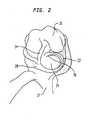
- FIG. 2there is shown the joint capsule of FIG. 1 with the inner portion of the meniscus 20 removed leaving meniscal rim 22.
- the incision/resection of the meniscus 20is made within or at the border of what is known as the red zone of the meniscus, i.e., the vascularized region of the meniscus.
- the resection of the inner part of meniscus 20leaves meniscal horns 26, 28 in place. Since the meniscal rim 22 remains, all the attachment points to the peripheral tibial plateau 24 are left and the surrounding ligaments and musculature is maintained through the meniscal rim.
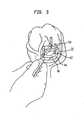
- a femoral alignment guide 30includes an alignment rod 32 which extends outwardly of the knee capsule and can be aligned with the femoral head and laid parallel to the femoral shaft in the frontal plane for referencing the location of the femoral sizing template. Specifically, implant flexion and implant rotation with regard to the frontal and sagittal planes can be set.
- a femoral sizing template 34is thus aligned with alignment guide 30 on the lateral condyle 10 of the femur.
- femoral sizing template 34includes a handle 36 and a posterior saw guide 38. The posterior saw guide 38 is used to make the posterior femoral cut via a slotted saw guide 40.
- template 42has a "D"-shaped outer surface 44 and a generally oval inner surface 46.
- template 42includes a handle 48 so that a straight side 50 of the "D"-shaped template 42 may be aligned with the meniscal horns 26, 28.
- a series of templates 42 of varying sizesare provided in a kit, each corresponding to a population of different size tibial plateaus. It is contemplated that a series of 5 to 7 templates 42 would be provided in a kit to be used during the surgical procedure. This is also true for template 34 in which a variety of sizes may be provided to accommodate different size femurs.
- template 42includes a series of through bores 52.
- FIG. 5there is shown the template 42 of FIG. 4 pinned in position utilizing three pins 54 which are sunk into the bone of the tibial plateau through holes 52 of "D"-shaped template 42.
- Pins 54locate template 42 on the tibial plateau in a location which, in the preferred embodiment, places a surface 44 of template 42 in close proximity of the remaining rim portion 22 of the natural meniscus.
- a burr or end mill 60which is used to form a recess surface in tibial plateau 24 having the shape of inner surface 46 of template 42. Burr 60 is driven by any convenient means via a drive shaft 62.
- burr 60includes a stop plate 64 which contacts an upper surface 48 of template 42. Stop plate 64 is set at a predetermined distance from the lower most cutting face of mill or burr 64 so that a depth of resection into the surface of tibial plateau 24 is set. In the preferred embodiment, this is at least .2 and preferably .24 inches.
- template 72having an outer surface 74 matching outer surface 44 of template 42.
- template 72includes a series of preferably three through holes 76 for receiving the same series of pins 54 as used for template 42.
- template 72includes an "I"-shaped inner recess 80. While recess 80 is preferably "I"-shaped, it is conceivable that other shapes may be used which would the keel of receive an implant to be discussed below and prevent the translation and rotation thereof.
- Resection template 72is located in a manner similar to that of resection template 42 and recess 80 is centrally located within the generally oval recess previously cut with template 42.
- template 72includes a handle 82 to facilitate its alignment on the tibial plateau.
- Pins 78are placed through throughbores 76 and the original pin holes used with template 42 to maintain the resection template 72 in its aligned orientation. Alternately the pins used to hold down template 42 can be left in place and template 72 can be slid over the remaining pins.
- a burr or end mill 84which is similar or identical to end mill 60, is utilized to form an "I"-shaped recess within the oval recess already formed. Obviously, this recess has to be deeper into the tibial bone than the original oval shaped recess formed.
- burr 84includes a stop plate 86 spaced at a greater distance from upper surface 88 of template 72 than stop 64 of burr or end mill 60.
- the thickness of template 42 and 72will be identical, however, the dimensions between the bottom surface end mill or burr 84 and the guide surface 88 is dimensioned to produce an "I"-shaped recess of the desired depth. In the preferred embodiment, this depth is 6,1 mm (.240 inches) and at least 5,1mm (.2 inches) below the recess surface initially formed in tibial plateau 24 with template 42.
- the recesshas a first recessed area 66 and a more recessed area, in the shape of an "I", 82.
- the size of the resection templates 42 and 72may change to match varying anatomy. In general, for each template 42 there will be a corresponding identically sized template 82. Consequently, if there are five templates 42 in a kit, there will be preferably five templates 82 in a kit. Thus, the size of the pockets or recesses 66, 82 will get larger as the template size increases. The use of the two depth recesses or pockets 66, 82 will be discussed below.
- template 90attached to lateral condyle 10 via pins 92.
- template 90includes a pair of through bores 94 for receiving pins for attaching template 90 to the femoral condyle 10.
- pins 92may be used.
- An end mill or burr similar to that discussed above with regard to elements 60, 84is used to mill a recess within the inner surface 96 of template 90. If a thin wall of bone is left due to the center island, that remaining portion of bone is resected free-handed with the burr.
- a recess 100is formed in the lateral condyle 10 of the femur.
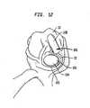
- Tibial implant 102includes an "I"-shaped keel 104 (shown in phantom in FIG. 12 ) which extends to the base of the "I"-shaped recess 82.
- Implant 102has a periphery 105 which has a portion extending into the upper level, i.e., extending at a lesser distance from the base of the tibial resurfacing implant 104 and engaging with outer recess 66.
- FIG. 14there is shown a bottom view of a preferred medial and lateral implant 102' and 102" each having a keel 104.
- the arcuate portion of the implantsis placed adjacent remaining rim 22 of a tibial plateau 107.
- the tibial implant 102is either press fit or cemented into recesses 66, 82.
- Femoral resurfacing implant 106has an outer bearing surface 108 shaped to be congruent with the natural surface of the femoral condyle 10.
- this componentwill be a cobalt chrome alloy implant having a thickness such that outer surface 108 is placed at or about the level of the natural femoral condyle 10 prior to resurfacing.
- implant 108may be either press fit or cemented into position.
- the femoral resurfacing implant 106may be made of a ceramic and cemented in position.
- tibial implant 104is preferably made of polyethylene having a porous surface contacting the bone.
- the tibial contactcan be made of polyurethane, cobalt chrome, ceramic or a polyvinyl alcohol hydrogel.
- meniscal implant 110which is positioned proximally of the resurfacing implant 104.
- meniscal implant 110is made of a polyvinyl alcohol hydrogel or a polyurethane but can be made of any biocompatible soft, compliant material that is able to withstand the loading in the knee joint and capable of the wear properties requires.
- a hydrogel meniscusis described in U.S. Publication No. 2002/0022884 published February 21, 2002 .
- the meniscusis made of a polyurethane which is molded to include an inner mesh or sutures.
- meniscal implant 110is attached to the meniscal rim 22 via the sutures or mesh integrally molded into the hydrogel implant. Preferably, this is done around the entire circumference 112 of implant 110 so that it is maintained in position by the remaining natural meniscal rim 22.
- the mesh of the implantfor example that shown in U.S. Patent No. 5,007,934 may be coated or impregnated with bioactive factors, tissue cultures, BMPs or other resorbable polymers to encourage potential soft tissue ingrowth. This ingrowth would supplement or, in some cases, replace the suture attachment to meniscal rim 22.
- the preferred surgical procedurewhich is not part of the claimed invention utilizes a minimally invasive method which, when compared to standard techniques current used for resurfacing the knee joint of other body joints, uses a smaller incision.
- the incision lengthis between 2 and 2 1/2 times the patellar width.
- Stepsshould also be taken to leave the quadriceps muscle 16 in its natural position by making sure it is not severed or twisted.
- Attachments to the peripheral tibial plateausuch as horns 26, 28 and surrounding ligaments and musculature should be maintained through the meniscal rim 22.
- the anterior cruciate ligament 14, if attached to the meniscal rimshould be maintained.
- the posterior surface of the femuris prepared. This is done using femoral alignment guide 30 which has rod 32 extending externally of the incision, which rod points to the femoral head. The rod indicates implant flexion and implant rotation within the frontal and sagittal planes.
- a femoral sizing template 34is used to measure and guide a posterior femoral cut. Obviously, there will be several different size templates corresponding to the several femoral implant sizes.
- the templatemay include guide 38 having saw blade slot 40 for preparing the posterior surface of the femur in a known manner.
- Tibial sizing template 42is then utilized to prepare the inner portion of the meniscus.
- the meniscuswill removed in an oval shape with the oval aligned via surface 50 with the two anatomic meniscal horns 26, 28.
- the template 42is pinned in position via pins 54 and burr 60 is used to mill pocket 66 into tibial plateau 24.
- a second "I" beam template 72is placed over pins 54 after the initial template 42 is removed and a deeper recess is formed within the initial cavity.
- the "I"-shaped pocket 88is deeper than the original "D"-shaped or oval pocket 66 to accommodate an "I"-shaped keel on the implant.
- the "I"-shaped keel receiving recessalso grows.
- the "D"-shaped pocket 66 formedshould encompass the maximum possible tibial plateau area within rim 22 with the "I"-shaped recess 82 in the center.
- a femoral burr template 90is pinned in position via pins 92 and a recess of general uniform depth is formed, as by milling with a burr similar to burr 60 along with the condyle 10 of the distal femur.
- a femoral implant 106preferably made of a cobalt chrome alloy such as Vitallium® alloy or a ceramic is implanted in the recess formed on the femoral condyle.
- this implanthas a thickness corresponding to the depth of the recess formed so that outer surface 108 of implant 106 is located at the correct anatomical position.
- a tibial resurfacing implant 104which may be circular or preferably have a general "D"-shape corresponding the various size template provided is implanted in recesses 66, 82. For each implant profile, several implant thicknesses are provided. The thickness is chosen such that the implant will be aligned in the varus/valgus direction. Once the implant thickness is determined, implant 104 will either be press fit or cemented into place.
- the tibial plateau implant bearing surfaceis preferably made of polyethylene and will have a porous metal surface against the bone. Alternatively, the tibial implant can be made of polyurethane, cobalt chrome, ceramics or a poly vinyl alcohol hydrogel. If the implant is made in the shape of a "D", the arcuate periphery of the "D" is located immediately inside the remaining rim 22 of the tibia.
- meniscal implant 10is attached to the remaining meniscal rim 22 such by suturing.
- a sizing templateis used to determine the required meniscal implant size in all three anatomical planes.
- the sizing templateis similar to the D-shaped resection template with the arcuate portion sizing the meniscal implant.
- the meniscus, which is attached to remaining rim 22 of tibial plateau 24preferably made of poly vinyl alcohol hydrogel or polyurethane but can be made of any biocompatible soft, compliant material that is able to withstand the functional loading and tribiological conditions.
- the implantis sutured into the remaining meniscal rim.
- the suturescan be made part of the implant such as by molding.
- the suturesmay be made integral with a mesh that is also molded into the implant.
- the meshcan abut the meniscal rim and allow for the potential of soft tissue ingrowth.
- Bioactive factorssuch as tissue cultures, resorbables, bone morphogenic proteins can be added to the mesh to encourage the tissue ingrowth.
Landscapes
- Health & Medical Sciences (AREA)
- Life Sciences & Earth Sciences (AREA)
- Orthopedic Medicine & Surgery (AREA)
- Veterinary Medicine (AREA)
- Animal Behavior & Ethology (AREA)
- Surgery (AREA)
- Oral & Maxillofacial Surgery (AREA)
- Engineering & Computer Science (AREA)
- Biomedical Technology (AREA)
- Heart & Thoracic Surgery (AREA)
- Public Health (AREA)
- General Health & Medical Sciences (AREA)
- Transplantation (AREA)
- Nuclear Medicine, Radiotherapy & Molecular Imaging (AREA)
- Molecular Biology (AREA)
- Medical Informatics (AREA)
- Dentistry (AREA)
- Physical Education & Sports Medicine (AREA)
- Cardiology (AREA)
- Vascular Medicine (AREA)
- Rheumatology (AREA)
- Prostheses (AREA)
- Acyclic And Carbocyclic Compounds In Medicinal Compositions (AREA)
Abstract
Description
- This invention relates to a resurfacing system for a joint capsule with a surgical implant designed to replace meniscal tissue and cartilage in a mammalian joint, such as a knee joint. While a knee is the primary joint of concern, the invention applies to other body joints as the hip, shoulder, elbow, temporomandibular, sternoclavicular, zygapophyseal, and wrist.
- Compared to the hip the knee has a much greater dependence on passive soft tissues (menisci, ligaments, and the joint capsule) for stability and function. Although the mechanics of the two joints are different, known hip and knee implants are very similar in design, both consisting of a semi-rigid on rigid (polyethylene on CoCr) bearing surface. In many prosthetic knee implants, function and mobility are impaired because rigid structures are used to replace the natural soft tissues.
- Normal anatomical knees have two pliable, mobile menisci that function to absorb shock, distribute stress, increase joint congruity, increase contact area, guide arthrokinematics, help lubrication by maintaining a fluid-film bearing surface, and provide proprioceptive input, i.e., nerve impulse via its attachment to the joint capsule. Even under physiologic loading a natural knee with natural menisci will primarily distribute stresses through a fluid film, only 10% of a load is transmitted via a solid on solid contact. Due to the fluid film bearing surface contact wear is greatly reduced. In simple terms the menisci function to reduce joint stresses, decrease wear, and help guide normal kinematics. Without menisci, peak contact stresses in the knee increase by 235% or more and degenerative changes start to progress rapidly. At 0°, 30°, and 60° of flexion, natural knees with intact menisci have approximately 6 to 8 times the contact area of typical prosthetic knee implants many of which have a similar geometry to that of a natural knee without menisci.
- Typical existing knee replacements lack the functional features normally provided by the menisci and the common polyethylene on metal such as cobalt chrome (CoCr) bearing interface lacks the wear-reducing fluid film bearing surface. By adding a well-designed meniscal substitute, many shortcomings of existing knee replacements can be addressed. In theory, prosthetic menisci could have the same impact on a prosthetic knee as natural menisci do for natural knees.
- The prosthetic knee meniscus of the present invention has at least one and preferably two compliant prosthetic menisci (medial and lateral in the knee) that are attached to the joint capsule and meniscal horns in a similar fashion to the way a natural meniscus is attached to a natural knee. Like a natural meniscus, the meniscal knee implant of the present invention will be able to pivot and glide on a prosthetic tibial plateau. Arthrokinematic constraint comes from the meniscal attachments and will gently guide movements, providing a highly mobile but stable joint. Also through its attachments, the Anatomical Meniscal-Bearing Knee will provide proprioceptive input, giving the central nervous system feedback for refined motor control.
- A preferred material for the meniscal implant of the present invention is polyurethane. Polyurethane can be made flexible so it can conform to the femoral and tibial components, thus giving the knee a large contact area throughout the entire range of motion. Such a polyurethane is described in
U.S. Patent No 5,879,387 . Alternatively, a hydrogel such as a poly(vinyl) alcohol can be used as a prosthetic meniscal implant. Such a hydrogel can be cross-linked to increase its strength and wear properties. Like cartilage, it imbibes aqueous fluids and generates a fluid-film bearing surface. - The flexible, pliable, gel-like nature of a synthetic hydrogel (when saturated with water) arises mainly from crosslinking attachments between non-parallel fibers in the gel. Depending on the specific polymeric structure that has been chosen, these crosslinking attachments between the long "backbone" chains in a polymer can be formed by covalent bonding, by hydrogen bonding or similar ionic attraction, or by entangling chains that have relatively long and/or "grabby" side-chains.
- Regardless of which type of bonding or entangling method is used to bind the backbone chains together to form a hydrogel, the "coupling" points between molecular chains can usually be flexed, rotated, and stretched.
- In addition, it should be recognized that the back-bone chains in hydrogel polymers are not straight; instead, because of various aspects of interatomic bonds, they are somewhat kinked, and can be stretched, in an elastic and springy manner, without breaking the bonds.
- In a typical hydrogel, the fibers usually take up less than about 10% of the volume; indeed, many hydrogels contain less than 2% fiber volume, while interstitial spaces (i.e., the unoccupied spaces nestled among the three-dimensional network of fibers, which become filled with water when the gel is hydrated) usually make up at least 90 to 95% of the total volume. Accordingly, since the "coupling" point between any two polymeric backbone chains can be rotated and flexed, and since any polymeric backbone molecule can be stretched without breaking it, a supple and resilient gel-like mechanical structure results when a synthetic hydrogel polymer is hydrated.
- Various methods are known for creating conventional polymeric hydrogels. A number of such methods involve mixing together and reacting precursor materials (monomers, etc.) while they are suspended in water or other solvent. This step (i.e., reacting two or more monomers while they are suspended in a solvent) gives a desired density and three-dimensional structure to the resulting polymerized strands or fibers. The resulting material is then frozen, to preserve the desired three-dimensional structure of the fibers. The ice (or other frozen solvent) is then vaporized and removed, without going through a liquid stage, by a sublimizing process (also called lyophilizing), using high vacuum and low temperature. After the solvent has been removed, any final steps (such as a final crosslinking reaction and/or rinsing or washing steps, to remove any unreacted monomers, crosslinking agents, quenching agents, etc.) are carried out. The polymer is then gradually warmed up to room temperature, and it is subsequently saturated with water, to form a completed hydrogel.
- In the past, effort mainly has been placed on the development of meniscal replacement. In the attempt to repair or replace torn menisci, allographs, xenographs, and autographs have been implanted for over 20 years. Current focus has been on the development of collagen-matrix meniscal implants. However, these implants do not reproduce the mechanical properties of a normal meniscus.
- As used herein, all references to "implants" or "implantation" (and all terms such as surgery, surgical, operation, etc.) refer to surgical or arthroscopic implantation of a reinforced hydrogel device, as disclosed herein, into a mammalian body or limb, such as in a human patient. Arthroscopic methods are regarded herein as a subset of surgical methods, and any reference to surgery, surgical, etc., includes arthroscopic methods and devices. The term "minimally invasive" is also used occasionally herein, even though it is imprecise; one should assume that any surgical operation will be done in a manner that is minimally invasive, in view of the needs of the patient and the goals of the surgeon.
- Meniscal Tissues in Knees - Each knee joint of a human contains a "medial" meniscus, and a "lateral" meniscus. The lateral meniscus is located on the outer side of the leg, directly above the location where the upper end of the fibula bone is coupled to the tibia ("shinbone"). The medial meniscus is located on the inner side of the leg.
- Each meniscus (also referred to, especially in older texts, as a "semilunar fibrocartilage") has a wedged shape, somewhat comparable to a segment from an orange or other citric fruit, but with a substantially larger curvature and "arc." The thickest region is around the periphery (which can also be called the circumference, the rim, and similar terms). When implanted into a knee, this peripheral rim normally will be anchored to the surrounding wall of a fibrous "capsule" which encloses the knee joint and holds in the synovial fluid, which lubricates the cartilage surfaces in the knee. The two ends of each semi-circular wedge are coupled, via thickened collagen structures called horns to the "spine" protrusions in the center of the tibial plateau.
- The inner edge of a meniscus is the thinnest portion of the wedge; this edge can also be called the apex, the margin, and similar terms. It is not anchored; instead, as the person walks or runs, each meniscus in a knee is somewhat free to move, as it is squeezed between the tibial plateau (beneath it) and a femoral runner or condyle (above it). The bottom surface of each meniscus is relatively flat, so it can ride in a relatively stable manner on top of the tibial plateau. The top surface is concave, so it can provide better, more closely conforming support to the rounded edge of the femoral runner. Because of its shape, location, and ability to flex and move somewhat as it is pushed, each meniscus helps support and stabilize the outer edge of a femoral runner, as the femoral runner presses, slides, and "articulates" against the portion of the tibial plateau beneath it.
- However, because all four of the menisci inside a person's knees are in high-stress locations, and are subjected to frequently-repeated combinations of compression and tension (and sometimes abrasion as well, especially in people suffering from arthritis or other forms of cartilage damage), meniscal damage often occurs in the knees of humans, and occasionally other large animals.
- It should be noted that, in humans, meniscal-type tissues also exist in temporomandibular, sternoclavicular, zygapophyseal, and wrist joints.
- Various efforts have been made, using prior technology, to repair or replace damaged meniscal tissue. However, because of the complex structures and anchoring involved, and because of the need to create and sustain extremely smooth and constantly wet surfaces on the inner portions of each meniscal wedge, prior methods of replacing or repairing damaged meniscal are not entirely adequate.
- Many meniscal implants for the knee address the need for attachment to the surrounding soft tissue but they do not address the need to resurface the femoral and/or the tibial articulating surfaces. An example of this type of implant is described by
Kenny U.S. Patent No. 4,344,193 andStone U.S. Patent No. 5,007,934 . - A free-floating cobalt chrome meniscal replacement has been designed to cover the tibial bearing surface. Because this implant is rigid and because it is disconnected from the soft tissues it lacks the ability to shock absorb and/or provide proprioceptive input. In fact, because it is approximately 10-20 times more rigid than bone it may actually cause concentrated loading, increased contacts stresses, and therefore accelerate degenerative joint changes.
- Various unicondylar knee implants for joint replacement contain a meniscus-like component. The tibial-bearing component of the known Oxford Knee (
British Patent Application No. 49794/74 - A resurfacing system for a joint capsule having cartilage and meniscal surfaces and comprising an artificial cartilage implant having a bone contacting surface and having a perimeter is known from
US 2002/147498 . - Another resurfacing system with features of the preamble of claim 1 is known from
US 2002/022889 . - Based on this prior art it is an object of the invention to provide a meniscal substitute to address shortcomings of existing knee replacements as mentioned above in order to provide prosthetic menisci having the same impact on a prosthetic knee as natural menisci do for natural knees.
- The anatomical meniscal-bearing knee implant of the present invention in characterized by the features of claim 1. It has one or more compliant prosthetic menisci that are attached to the joint capsule and meniscal horns in a similar fashion to the way a natural meniscus is attached to a natural knee. Like a natural meniscus, the meniscal implant will be able to pivot and glide on the prosthetic tibial plateau. Arthrokinematic constraint will come from the meniscal implant's attachments, which will gently guide movements, providing a highly mobile but stable joint. Also through its attachments, the Anatomical Meniscal-Bearing Knee will provide proprioceptive input, giving the central nervous system feedback for refined motor control. Like a natural knee with intact menisci, the outer border of the menisci implants will be mechanically linked to the tibial plateau via the coronary ligament, such as for example by the implant being attached such as by its being sutured directly to the joint capsule/coronary ligament or indirectly by attaching it to the remaining meniscal rim which is in turn attached to the coronary ligament. Tendon slips from the quadriceps, attached to both medial and lateral meniscus, will pull the meniscal replacements forward during active extension and likewise, the semimembranosus (medial meniscus) and/or popliteus tendons (lateral meniscus) will pull the meniscal replacements posteriorly during active flexion.
- The proposed anatomical meniscal-bearing arthroplasty has one or multiple prosthetic menisci that are attached to either the diarthrodial joint capsule and/or the remnant of the natural menisci. The knee will be used to describe the preferred embodiment of this concept. However, the proposed meniscal bearing can be used to repair cartilage in other body joints.
- The prosthetic is preferably implanted in the knee via a minimally invasive procedure, leaving the quadriceps muscle group intact. A small arthrotomy will be performed, allowing the access to the knee joint. Then the central portion of the meniscus will be resected, leaving the horns, a peripheral meniscal rim, and the coronary ligament intact. One or more well-defined cavities will then be formed in the articular surfaces of the tibia and/or femur. One or more resurfacing implants would then either be press-fit, cemented or sutured into the prepared pocket. The meniscal prosthetic is then sewed into the meniscal rim.
- The non-meniscal articular resurfacing portion of the implants which contact the meniscus consists of cobalt chrome alloys, stainless steel, ceramics, polyethylene, and/or polyurethane and will closely approximate the normal articular geometry.
- The bulk of the meniscal prosthetic implant will preferably consist of a compliant polyvinyl alcohol polymer and/or polyurethane. A meshed fabric may be molded into the peripheral rim of the prosthetic body, allowing biological glues and/or sutures to connect the implant to the surrounding soft tissue. If the entire original meniscus needs to be removed, a flexible tube can be placed in the space bordered by the tibial plateau, coronary ligament, and anatomical meniscus in order to measure the natural soft tissue laxity. Different diameters of tubing represent different amounts of laxity/mobility in the natural meniscus/coronary ligament construct. This tubing can then be reused as a spacer to balance the soft tissue connections, simulating the restraint of the natural meniscus.
- One preferred material for the meniscal implant is polyurethane. Polyurethane can be made flexible so it can conform to the femoral and tibial components, thus giving the knee a large contact area throughout the entire range of motion. Likewise, a polyvinyl alcohol polymer which imbibes aqueous fluids can be used. Like cartilage, it imbibes aqueous fluids and generates a fluid-film-bearing surface.
- The shape of the meniscal implants will closely conform to the tibial plateaus and femoral condyles, generating large areas of contact. They can either be congruent or, to distribute stresses more evenly they can be slightly incongruent as described byGoodfellow et al., The Design of Synovial Joints, Scientific Foundations of Orthopaedics and Traumatology, pp. 78-88. The meniscal portions of the implant will be flexible so they can conform to the tibial and femoral bearing surfaces throughout the entire range of motion.
- The anatomical meniscal-bearing concept could also be used in a unicondylar knee replacement. Because the meniscal portion of the implant is able to spin and glide on the tibial plateau, and because the meniscal replacement is flexible, the implant will be less sensitive to malaligement. With existing unicondylar knee replacements if the implant is malaligned the entire joint will likely experience abnormal stresses.
- Another possible use for this implant would be in the meniscal replacement surgery. The meniscal portion of the implant can be used by itself, being sewed to the joint capsule and meniscal horns of the knee. Also, variation in the meniscal implant can be made for replacement of menisci from other joints, i.e., sternoclavicular, temperomandibular, and zygapophyseal.
- The implant according to the invention can be used within a surgical procedure which is minimally invasive when compared to standard techniques currently used for resurfacing the knee joint or other body joints. In this method, the incision length is limited between 2 and 2 1/2 times the patellar width. During forming the incision, the surgeon should avoid turning the patella (everting) over from its natural position. Steps should also be taken to leave the quadriceps muscle in its natural position by making sure it is not severed or twisted. Attachments to the peripheral tibial plateau, horns and surrounding ligaments and musculature is maintained through the meniscal rim. For example, the anterior cruciate ligament, if attached to the meniscal rim, should be maintained. Likewise, the transverse ligament should be left attached to the meniscal horns. The inner portion of the meniscus is then removed. Preferably, the incision/resection is made within or at the border of the zone of the meniscus known as the red or vascularized region. Tibial sizing guides are used to measure the size of the meniscal resection (length of resection arc and thickness at the red-zone border).
- If femoral resurfacing is needed, the femoral resection may be done using a femoral alignment guide which has a rod extending externally of the incision, which rod points to the femoral head. The rod indicates implant flexion and implant rotation within the frontal plane. Once properly aligned, a femoral sizing template is used to measure and guide a posterior femoral cut. Obviously, there will be several different size templates corresponding to the several femoral implant sizes. The template may include a saw blade slot for preparing the posterior surface of the femur.
- A tibial-sizing tray is utilized to prepare the tibial bone cuts within the inner portion of the meniscus. Preferably, the meniscus will be removed in an oval or "D"-shape with the oval aligned with the two anatomic meniscal horns. Obviously, again, there are various size templates corresponding to different size tibias. Once aligned, the tray template is pinned in position and a burr or end mill is used to mill a pocket into the tibial plateau. A second template or deeper layer of the first template-shaped like an "I" beam (if a second template is used, it is placed over the pins after the initial template is removed) and a deeper recess is formed within the initial recess or cavity. In other words, the "I"-shaped pocket is deeper than the original "D"-shaped or oval pocket to accommodate an "I"-shaped keel on the implant. Preferably as the "D"-shaped pockets grow in size, the "I"-shaped keel receiving recess also increases, however, it may remain the same size if desired. The "D"-shaped pocket formed should encompass the entire tibial plateau within the rim with the "I"-shaped recess in the center.
- On the femoral side, a femoral burr template is pinned in position and a recess of general uniform depth is formed, as by milling with a burr, along the condyle of the distal femur. A femoral implant, preferably made of a cobalt chrome alloy such as Vitallium® alloy or a ceramic material is implanted in the recess formed on the femoral condyle. Preferably, this implant has a thickness corresponding to the depth of the recess formed so that the outer surface of the implant is located at the correct anatomical position.
- A tibial resurfacing implant is provided and has a "D"-shaped corresponding the various size templates provided. For each implant profile, several implant thicknesses are provided. The thickness is chosen such that the implant will be aligned in the varus/valgus direction. Once the implant thickness is determined, the actual implant will either be press fit or cemented into place. The tibial plateau implant has a contact surface preferably made of polyethylene and will have a porous titanium surface against the bone. The bone contacting porous surface attached to the polyethylene preferably is made of titanium or cobalt chrome or any other biocompatible porous material. Alternatively, the tibial implant can be made of polyurethane, cobalt chrome, ceramics, or a polyvinyl alcohol hydrogel. Alternatively, the implant may be in the shape of a circular disc with a periphery located immediately inside the remaining rim of the tibia.
- Once the tibial plateau is resurfaced, a meniscal implant is attached to the remaining meniscal rim such by suturing. A sizing template is used to determine the required implant size in all three anatomical planes. The meniscus, which is attached to the remaining rim of the tibial plateau is preferably made of a polyvinyl alcohol hydrogel or a polyurethane but can be made of any biocompatible soft, compliant material that is able to withstand the functional loading and tribiological conditions. The implant is sutured into the remaining meniscal rim. The sutures can be made part of the implant such as by molding. See, for example, the implant of
Kenny U.S. Patent No. 4,344,193 . The sutures may be made integral with a mesh that is also molded into the implant. The mesh can abut the meniscal rim and allow for the potential of soft tissue ingrowth. Bioactive factors such as tissue cultures, resorbables, bone morphogenic proteins can be added to the mesh to encourage the tissue ingrowth. SeeStone U.S. Patent No. 5,007,934 . FIG. 1 is an isometric view of a knee joint capsule showing the exposed tibial meniscal portions;FIG. 2 shows the capsule ofFIG. 1 after removal of the central portion of the lateral meniscus but leaving a meniscal rim;FIG. 3 shows the location of a femoral sizing template and alignment guide mounted within the joint capsule;FIG. 4 shows a tibial tray sizing template located within the remaining meniscal rim on the tibial plateau;FIG. 5 shows the template ofFIG. 4 pinned in a position aligned with the meniscal horns;FIG. 6 shows a burr used to mill a pocket in the tibial plateau conforming to the tibial sizing template;FIG. 7 shows an "I" beam template placed within the pocket milled inFIG. 6 on the resected tibial plateau;FIG. 8 shows the "I" beam template ofFIG. 7 pinned in position;FIG. 9 shows a burr shaping the "I"-shaped pocket;FIG. 10 shows the "I"-shaped pocket ofFIG. 9 within the oval or "D"-shaped pocket formed inFIG. 6 along with a femoral burr template for forming a recess in the lateral femoral condyle;FIG. 11 shows the recess formed inFIG. 10 ;FIG. 12 shows both the femoral resurfacing implant on the femur and the tibial resurfacing implant attached to the tibial plateau;FIG. 13 shows the tibial resurfacing implant ofFIG. 12 covered by a compliant meniscal implant which is attached to the remaining natural meniscal rim; andFIG. 14 is a bottom view of a medial and lateral tibial resurfacing implant including lateral implants ofFIGS. 12 and13 .- Referring to
FIG. 1 there is shown, for purposes of reference, an open knee joint capsule including a lateralfemoral condylar surface 10 and a medialfemoral condylar surface 12. The anteriorcruciate ligament 14 is shown running through the joint. Thequadriceps 16 is shown coupled to thetibia 17 and thelateral collateral ligament 18 is shown connecting the tibia and the femur. Thelateral meniscus 20 which includes arim area 22 is located above thetibial plateau 24. - Referring to
FIG. 2 , there is shown the joint capsule ofFIG. 1 with the inner portion of themeniscus 20 removed leavingmeniscal rim 22. In the preferred method, which will be discussed below, the incision/resection of themeniscus 20 is made within or at the border of what is known as the red zone of the meniscus, i.e., the vascularized region of the meniscus. The resection of the inner part ofmeniscus 20 leavesmeniscal horns meniscal rim 22 remains, all the attachment points to theperipheral tibial plateau 24 are left and the surrounding ligaments and musculature is maintained through the meniscal rim. - Referring to
FIG. 3 , afemoral alignment guide 30 includes analignment rod 32 which extends outwardly of the knee capsule and can be aligned with the femoral head and laid parallel to the femoral shaft in the frontal plane for referencing the location of the femoral sizing template. Specifically, implant flexion and implant rotation with regard to the frontal and sagittal planes can be set. Afemoral sizing template 34 is thus aligned withalignment guide 30 on thelateral condyle 10 of the femur. In the preferred embodiment,femoral sizing template 34 includes ahandle 36 and a posterior sawguide 38. The posterior sawguide 38 is used to make the posterior femoral cut via a slottedsaw guide 40. - With regard to
FIG. 4 , there is shown atibial sizing template 42. In the preferred embodiment,template 42 has a "D"-shapedouter surface 44 and a generally ovalinner surface 46. In the preferred embodiment,template 42 includes ahandle 48 so that astraight side 50 of the "D"-shapedtemplate 42 may be aligned with themeniscal horns templates 42 of varying sizes are provided in a kit, each corresponding to a population of different size tibial plateaus. It is contemplated that a series of 5 to 7templates 42 would be provided in a kit to be used during the surgical procedure. This is also true fortemplate 34 in which a variety of sizes may be provided to accommodate different size femurs. In the preferred embodiment,template 42 includes a series of throughbores 52. - Referring to
FIG. 5 , there is shown thetemplate 42 ofFIG. 4 pinned in position utilizing threepins 54 which are sunk into the bone of the tibial plateau throughholes 52 of "D"-shapedtemplate 42.Pins 54 locatetemplate 42 on the tibial plateau in a location which, in the preferred embodiment, places asurface 44 oftemplate 42 in close proximity of the remainingrim portion 22 of the natural meniscus. As can be seen inFIG. 6 , there is shown a burr orend mill 60 which is used to form a recess surface intibial plateau 24 having the shape ofinner surface 46 oftemplate 42.Burr 60 is driven by any convenient means via adrive shaft 62. In the preferred embodiment,burr 60 includes astop plate 64 which contacts anupper surface 48 oftemplate 42. Stopplate 64 is set at a predetermined distance from the lower most cutting face of mill orburr 64 so that a depth of resection into the surface oftibial plateau 24 is set. In the preferred embodiment, this is at least .2 and preferably .24 inches. - Referring to
FIGS. 7 and8 , there is shown asecond template 72 having anouter surface 74 matchingouter surface 44 oftemplate 42. As shown inFIG. 8 ,template 72 includes a series of preferably three throughholes 76 for receiving the same series ofpins 54 as used fortemplate 42. In the preferred embodiment,template 72 includes an "I"-shapedinner recess 80. Whilerecess 80 is preferably "I"-shaped, it is conceivable that other shapes may be used which would the keel of receive an implant to be discussed below and prevent the translation and rotation thereof.Resection template 72 is located in a manner similar to that ofresection template 42 andrecess 80 is centrally located within the generally oval recess previously cut withtemplate 42. - In the preferred embodiment,
template 72 includes ahandle 82 to facilitate its alignment on the tibial plateau.Pins 78 are placed throughthroughbores 76 and the original pin holes used withtemplate 42 to maintain theresection template 72 in its aligned orientation. Alternately the pins used to hold downtemplate 42 can be left in place andtemplate 72 can be slid over the remaining pins. - Referring to
FIG. 9 , a burr orend mill 84, which is similar or identical to endmill 60, is utilized to form an "I"-shaped recess within the oval recess already formed. Obviously, this recess has to be deeper into the tibial bone than the original oval shaped recess formed. Thus,burr 84 includes astop plate 86 spaced at a greater distance fromupper surface 88 oftemplate 72 than stop 64 of burr orend mill 60. Generally, the thickness oftemplate burr 84 and theguide surface 88 is dimensioned to produce an "I"-shaped recess of the desired depth. In the preferred embodiment, this depth is 6,1 mm (.240 inches) and at least 5,1mm (.2 inches) below the recess surface initially formed intibial plateau 24 withtemplate 42. - Referring to
FIG. 10 there is shown the two level recess formed inplateau 24. As discussed above, the recess has a first recessedarea 66 and a more recessed area, in the shape of an "I", 82. As indicated above, the size of theresection templates template 42 there will be a corresponding identicallysized template 82. Consequently, if there are fivetemplates 42 in a kit, there will be preferably fivetemplates 82 in a kit. Thus, the size of the pockets or recesses 66, 82 will get larger as the template size increases. The use of the two depth recesses orpockets - Referring again to
FIG. 10 , there is shown afemoral burr template 90 attached tolateral condyle 10 via pins 92. In the preferred embodiment,template 90 includes a pair of throughbores 94 for receiving pins for attachingtemplate 90 to thefemoral condyle 10. Obviously,more pins 92 than two may be used. An end mill or burr similar to that discussed above with regard toelements inner surface 96 oftemplate 90. If a thin wall of bone is left due to the center island, that remaining portion of bone is resected free-handed with the burr. - As best seen in
FIG. 11 , arecess 100 is formed in thelateral condyle 10 of the femur. - Referring to
FIGS. 12-14 , there is shown the tibial andfemoral resurfacing implants Tibial implant 102 includes an "I"-shaped keel 104 (shown in phantom inFIG. 12 ) which extends to the base of the "I"-shapedrecess 82.Implant 102 has aperiphery 105 which has a portion extending into the upper level, i.e., extending at a lesser distance from the base of thetibial resurfacing implant 104 and engaging withouter recess 66. Referring toFIG. 14 , there is shown a bottom view of a preferred medial andlateral implant 102' and 102" each having akeel 104. The arcuate portion of the implants is placed adjacent remainingrim 22 of atibial plateau 107. Thetibial implant 102 is either press fit or cemented intorecesses Femoral resurfacing implant 106 has anouter bearing surface 108 shaped to be congruent with the natural surface of thefemoral condyle 10. Preferably, this component will be a cobalt chrome alloy implant having a thickness such thatouter surface 108 is placed at or about the level of the naturalfemoral condyle 10 prior to resurfacing. Again,implant 108 may be either press fit or cemented into position. Alternately, thefemoral resurfacing implant 106 may be made of a ceramic and cemented in position. In the preferred embodiment,tibial implant 104 is preferably made of polyethylene having a porous surface contacting the bone. Alternately, the tibial contact can be made of polyurethane, cobalt chrome, ceramic or a polyvinyl alcohol hydrogel. - Referring to
FIG. 13 , there is shown ameniscal implant 110 which is positioned proximally of theresurfacing implant 104. In the preferred embodiment,meniscal implant 110 is made of a polyvinyl alcohol hydrogel or a polyurethane but can be made of any biocompatible soft, compliant material that is able to withstand the loading in the knee joint and capable of the wear properties requires. Such a hydrogel meniscus is described inU.S. Publication No. 2002/0022884 published February 21, 2002 . - In the most preferred embodiment, the meniscus is made of a polyurethane which is molded to include an inner mesh or sutures. In the preferred embodiment,
meniscal implant 110 is attached to themeniscal rim 22 via the sutures or mesh integrally molded into the hydrogel implant. Preferably, this is done around theentire circumference 112 ofimplant 110 so that it is maintained in position by the remaining naturalmeniscal rim 22. The mesh of the implant, for example that shown inU.S. Patent No. 5,007,934 may be coated or impregnated with bioactive factors, tissue cultures, BMPs or other resorbable polymers to encourage potential soft tissue ingrowth. This ingrowth would supplement or, in some cases, replace the suture attachment tomeniscal rim 22. - While only the resurfacing of the lateral side of the tibial plateau and femur have been described, the process could as easily be used on the
medial condyle 12 and medial tibial plateau. - The preferred surgical procedure which is not part of the claimed invention utilizes a minimally invasive method which, when compared to standard techniques current used for resurfacing the knee joint of other body joints, uses a smaller incision. In this preferred method, the incision length is between 2 and 2 1/2 times the patellar width. During forming the incision, everything or turning the patella over from its nature position should be avoided. Steps should also be taken to leave the
quadriceps muscle 16 in its natural position by making sure it is not severed or twisted. Attachments to the peripheral tibial plateau such ashorns meniscal rim 22. For example, the anteriorcruciate ligament 14, if attached to the meniscal rim, should be maintained. Likewise the transverse ligament should be left attached to the meniscal horns. Initially, the posterior surface of the femur is prepared. This is done usingfemoral alignment guide 30 which hasrod 32 extending externally of the incision, which rod points to the femoral head. The rod indicates implant flexion and implant rotation within the frontal and sagittal planes. Once properly aligned, afemoral sizing template 34 is used to measure and guide a posterior femoral cut. Obviously, there will be several different size templates corresponding to the several femoral implant sizes. The template may include guide 38 havingsaw blade slot 40 for preparing the posterior surface of the femur in a known manner. Tibial sizing template 42 is then utilized to prepare the inner portion of the meniscus. Preferably, the meniscus will removed in an oval shape with the oval aligned viasurface 50 with the two anatomicmeniscal horns various size templates 42 corresponding to different size tibias. Once aligned, thetemplate 42 is pinned in position via pins 54 andburr 60 is used tomill pocket 66 intotibial plateau 24. A second "I"beam template 72 is placed overpins 54 after theinitial template 42 is removed and a deeper recess is formed within the initial cavity. In other words, the "I"-shapedpocket 88 is deeper than the original "D"-shaped oroval pocket 66 to accommodate an "I"-shaped keel on the implant. Preferably, as the "D"-shaped pockets grow in size, the "I"-shaped keel receiving recess also grows. The "D"-shapedpocket 66 formed should encompass the maximum possible tibial plateau area withinrim 22 with the "I"-shapedrecess 82 in the center.- On the femoral side, a
femoral burr template 90 is pinned in position via pins 92 and a recess of general uniform depth is formed, as by milling with a burr similar toburr 60 along with thecondyle 10 of the distal femur. Afemoral implant 106, preferably made of a cobalt chrome alloy such as Vitallium® alloy or a ceramic is implanted in the recess formed on the femoral condyle. Preferably, this implant has a thickness corresponding to the depth of the recess formed so thatouter surface 108 ofimplant 106 is located at the correct anatomical position. - A
tibial resurfacing implant 104 which may be circular or preferably have a general "D"-shape corresponding the various size template provided is implanted inrecesses implant 104 will either be press fit or cemented into place. The tibial plateau implant bearing surface is preferably made of polyethylene and will have a porous metal surface against the bone. Alternatively, the tibial implant can be made of polyurethane, cobalt chrome, ceramics or a poly vinyl alcohol hydrogel. If the implant is made in the shape of a "D", the arcuate periphery of the "D" is located immediately inside the remainingrim 22 of the tibia. - Once the tibial plateau is resurfaced with
implant 104,meniscal implant 10 is attached to the remainingmeniscal rim 22 such by suturing. A sizing template is used to determine the required meniscal implant size in all three anatomical planes. The sizing template is similar to the D-shaped resection template with the arcuate portion sizing the meniscal implant. The meniscus, which is attached to remainingrim 22 oftibial plateau 24 preferably made of poly vinyl alcohol hydrogel or polyurethane but can be made of any biocompatible soft, compliant material that is able to withstand the functional loading and tribiological conditions. The implant is sutured into the remaining meniscal rim. The sutures can be made part of the implant such as by molding. See, for example, the implant of KennyU.S. Patent No. 4,344,193 . The sutures may be made integral with a mesh that is also molded into the implant. The mesh can abut the meniscal rim and allow for the potential of soft tissue ingrowth. Bioactive factors such as tissue cultures, resorbables, bone morphogenic proteins can be added to the mesh to encourage the tissue ingrowth. - Although the invention herein has been described with reference to particular embodiments, it is to be understood that these embodiments are merely illustrative of the principles and applications of the present invention. It is therefore to be understood that numerous modifications may be made to the illustrative embodiments and that other arrangements may be devised without departing from the scope of the present invention as defined by the appended claims.
Claims (14)
- A resurfacing system for a joint capsule having cartilage and meniscal surfaces, comprising:- an artificial cartilage implant (102) having a bone contacting surface and having a perimeter,characterized in that the system further comprises:- a soft compliant artificial meniscal implant (110),wherein the cartilage implant (102) has a keel (104) insertable in said bone contacting surface preventing the translation and rotation thereof, wherein the artificial meniscal implant (110) surrounds at least part of the artificial cartilage implant (102) and glides and spins on the tibial plateau and wherein the meniscal implant (110) includes apertures for suturing the meniscal implant to a meniscal rim of the original joint meniscus.
- The resurfacing system as claimed in claim 1, wherein the keel (104) of the cartilage implant (102) is "I"-shaped.
- The resurfacing system as claimed in claim 2, wherein the cartilage implant (102) has a periphery (105) above the "I" shaped keel (104) adapted to receive the artificial meniscal implant (110).
- The resurfacing system as claimed in any preceding claim,
wherein the cartilage implant bone contacting surface is formed of a porous material. - The resurfacing system as claimed in any preceding claim,
wherein the cartilage implant bone contacting surface is formed of titanium or a cobalt chrome alloy. - The resurfacing system as claimed in Claim 5, wherein the cobalt chrome alloy meets the ASTM F 75 standard.
- The resurfacing system as claimed in any preceding claim,
wherein the cartilage implant is formed of polyurethane, polyethylene, a cobalt chrome alloy, a ceramic or a polyvinyl alcohol hydrogel. - The resurfacing system as claimed in Claim 7, wherein the ceramic is selected from alumina, zirconia, zirconia toughened alumina, diamond and diamond-like carbon.
- The resurfacing system as claimed in any preceding claim,
wherein the meniscal implant (110) is made from a polyvinyl alcohol hydrogel polymer or a polyurethane polymer. - The resurfacing system as claimed in Claim 9, wherein a mesh fabric is moulded in said polymer.
- The resurfacing system as claimed in any preceding claim,
wherein said cartilage implant (102) is having a polymeric bearing surface, preferably made of polyethylene, and wherein said meniscal implant (110) is made of polyurethane. - A kit of parts for resurfacing a tibial joint surface comprising:- a plurality of resurfacing systems, each according to one of claims 1 to 11,- a plurality of templates (42) for guiding the milling of bone underlying the joint surface; and- at least one cutting element (60) for engaging said template.
- A kit of parts as claimed in Claim 12, wherein said templates (42) have a D-shape.
- A kit of part as claimed in Claim 12, wherein said cutting element (60) is a burr having a drive shaft (62) with a stop surface (64) for engaging a surface on said templates (42).
Applications Claiming Priority (2)
| Application Number | Priority Date | Filing Date | Title |
|---|---|---|---|
| US10/356,263US6994730B2 (en) | 2003-01-31 | 2003-01-31 | Meniscal and tibial implants |
| US356263 | 2003-01-31 |
Publications (2)
| Publication Number | Publication Date |
|---|---|
| EP1442726A1 EP1442726A1 (en) | 2004-08-04 |
| EP1442726B1true EP1442726B1 (en) | 2008-04-30 |
Family
ID=32655605
Family Applications (1)
| Application Number | Title | Priority Date | Filing Date |
|---|---|---|---|
| EP04250525AExpired - LifetimeEP1442726B1 (en) | 2003-01-31 | 2004-01-30 | Meniscal and tibial implants |
Country Status (4)
| Country | Link |
|---|---|
| US (1) | US6994730B2 (en) |
| EP (1) | EP1442726B1 (en) |
| AT (1) | ATE393610T1 (en) |
| DE (1) | DE602004013383T2 (en) |
Cited By (6)
| Publication number | Priority date | Publication date | Assignee | Title |
|---|---|---|---|---|
| US8142510B2 (en) | 2007-03-30 | 2012-03-27 | Depuy Products, Inc. | Mobile bearing assembly having a non-planar interface |
| US8147557B2 (en) | 2007-03-30 | 2012-04-03 | Depuy Products, Inc. | Mobile bearing insert having offset dwell point |
| US8147558B2 (en) | 2007-03-30 | 2012-04-03 | Depuy Products, Inc. | Mobile bearing assembly having multiple articulation interfaces |
| US8328874B2 (en) | 2007-03-30 | 2012-12-11 | Depuy Products, Inc. | Mobile bearing assembly |
| US8764841B2 (en) | 2007-03-30 | 2014-07-01 | DePuy Synthes Products, LLC | Mobile bearing assembly having a closed track |
| WO2019077045A1 (en) | 2017-10-19 | 2019-04-25 | Friedrich-Alexander-Universität Erlangen-Nürnberg | Implant |
Families Citing this family (92)
| Publication number | Priority date | Publication date | Assignee | Title |
|---|---|---|---|---|
| US20050209703A1 (en)* | 1999-04-02 | 2005-09-22 | Fell Barry M | Surgically implantable prosthetic system |
| US7338524B2 (en)* | 1999-05-10 | 2008-03-04 | Fell Barry M | Surgically implantable knee prosthesis |
| US7297161B2 (en)* | 1999-05-10 | 2007-11-20 | Fell Barry M | Surgically implantable knee prosthesis |
| US7491235B2 (en)* | 1999-05-10 | 2009-02-17 | Fell Barry M | Surgically implantable knee prosthesis |
| US20050033424A1 (en)* | 1999-05-10 | 2005-02-10 | Fell Barry M. | Surgically implantable knee prosthesis |
| US6702821B2 (en) | 2000-01-14 | 2004-03-09 | The Bonutti 2003 Trust A | Instrumentation for minimally invasive joint replacement and methods for using same |
| US7635390B1 (en) | 2000-01-14 | 2009-12-22 | Marctec, Llc | Joint replacement component having a modular articulating surface |
| US7708741B1 (en) | 2001-08-28 | 2010-05-04 | Marctec, Llc | Method of preparing bones for knee replacement surgery |
| US20060147332A1 (en) | 2004-12-30 | 2006-07-06 | Howmedica Osteonics Corp. | Laser-produced porous structure |
| AU2003261497B2 (en) | 2002-11-08 | 2009-02-26 | Howmedica Osteonics Corp. | Laser-produced porous surface |
| US20090088846A1 (en) | 2007-04-17 | 2009-04-02 | David Myung | Hydrogel arthroplasty device |
| US7235592B2 (en) | 2004-10-12 | 2007-06-26 | Zimmer Gmbh | PVA hydrogel |
| US20060095048A1 (en) | 2004-10-29 | 2006-05-04 | Zannis Anthony D | Method of repairing soft tissue using sizing templates |
| JP4797364B2 (en)* | 2004-11-18 | 2011-10-19 | 三菱マテリアル株式会社 | Composite metal porous body and method for producing the same |
| CA2591921A1 (en) | 2005-02-23 | 2006-08-31 | Zimmer Technology, Inc. | Blend hydrogels and methods of making |
| US20060224244A1 (en)* | 2005-03-31 | 2006-10-05 | Zimmer Technology, Inc. | Hydrogel implant |
| US20060235542A1 (en)* | 2005-04-15 | 2006-10-19 | Zimmer Technology, Inc. | Flexible segmented bearing implant |
| US20060247769A1 (en)* | 2005-04-28 | 2006-11-02 | Sdgi Holdings, Inc. | Polycrystalline diamond compact surfaces on facet arthroplasty devices |
| US20070021838A1 (en)* | 2005-07-22 | 2007-01-25 | Dugas Jeffrey R | Site specific minimally invasive joint implants |
| CA2621019A1 (en)* | 2005-08-31 | 2007-03-08 | Zimmer Gmbh | Implant |
| US20070088444A1 (en)* | 2005-10-13 | 2007-04-19 | Robert A Hodorek | Method for repairing a bone defect using a formable implant which hardens in vivo |
| EP1973498B1 (en)* | 2005-11-09 | 2014-04-23 | Zimmer GmbH | Implant |
| US8728387B2 (en) | 2005-12-06 | 2014-05-20 | Howmedica Osteonics Corp. | Laser-produced porous surface |
| CA2632120C (en) | 2005-12-07 | 2014-07-08 | Zimmer, Inc. | Methods of bonding or modifying hydrogels using irradiation |
| DE602006017160D1 (en) | 2005-12-22 | 2010-11-11 | Zimmer Inc | Perfluorocyclobutane crosslinked hydrogels |
| US20070179607A1 (en)* | 2006-01-31 | 2007-08-02 | Zimmer Technology, Inc. | Cartilage resurfacing implant |
| WO2007090790A2 (en)* | 2006-02-09 | 2007-08-16 | Zimmer Gmbh | Implant |
| US8110242B2 (en) | 2006-03-24 | 2012-02-07 | Zimmer, Inc. | Methods of preparing hydrogel coatings |
| WO2007125060A1 (en)* | 2006-04-28 | 2007-11-08 | Zimmer Gmbh | Implant |
| US20070293947A1 (en)* | 2006-06-19 | 2007-12-20 | Mansmann Kevin A | Multi-part implants for combined repair of hyaline and meniscal cartilage in joints |
| US8540778B2 (en)* | 2006-06-22 | 2013-09-24 | DePuy Synthes Products, LLC | Tibial insert having multiple keels |
| US8147861B2 (en)* | 2006-08-15 | 2012-04-03 | Howmedica Osteonics Corp. | Antimicrobial implant |
| US8192491B2 (en) | 2006-10-09 | 2012-06-05 | Active Implants Corporation | Meniscus prosthetic device |
| EP2076218B1 (en) | 2006-10-09 | 2016-03-09 | Active Implants Corporation | Meniscus prosthetic device |
| US20080097606A1 (en)* | 2006-10-19 | 2008-04-24 | Cragg Andrew H | Knee joint prosthesis and hyaluronate compositions for treatment of osteoarthritis |
| CA2618125A1 (en)* | 2007-02-08 | 2008-08-08 | Zimmer, Inc. | Hydrogel proximal interphalangeal implant |
| US9814581B2 (en) | 2007-02-26 | 2017-11-14 | Marvin Schwartz | Mobile prosthesis for interpositional location between bone joint articular surfaces and method of use |
| US7670381B2 (en)* | 2007-02-26 | 2010-03-02 | Marvin Schwartz | Prosthesis for interpositional location between bone joint articular surfaces and method of use |
| US8506637B2 (en) | 2007-02-26 | 2013-08-13 | Marvin Schwartz | Mobile prosthesis for interpositional location between bone joint articular surfaces and method of use |
| US8162961B2 (en) | 2007-07-23 | 2012-04-24 | Zimmer Orthobiologies, Inc. | Medical devices and methods for cutting and suturing biological tissue |
| WO2009014718A1 (en) | 2007-07-24 | 2009-01-29 | Porex Corporation | Porous laser sintered articles |
| WO2009018128A2 (en)* | 2007-07-31 | 2009-02-05 | Zimmer, Inc. | Joint space interpositional prosthetic device with internal bearing surfaces |
| US20100131069A1 (en)* | 2007-08-01 | 2010-05-27 | Jeffrey Halbrecht | Method and system for patella tendon realignment |
| US20100198354A1 (en)* | 2007-08-01 | 2010-08-05 | Jeffrey Halbrecht | Method and system for patella tendon realignment |
| US7731988B2 (en) | 2007-08-03 | 2010-06-08 | Zimmer, Inc. | Multi-polymer hydrogels |
| US8062739B2 (en) | 2007-08-31 | 2011-11-22 | Zimmer, Inc. | Hydrogels with gradient |
| US8128703B2 (en) | 2007-09-28 | 2012-03-06 | Depuy Products, Inc. | Fixed-bearing knee prosthesis having interchangeable components |
| US8632600B2 (en) | 2007-09-25 | 2014-01-21 | Depuy (Ireland) | Prosthesis with modular extensions |
| US9204967B2 (en) | 2007-09-28 | 2015-12-08 | Depuy (Ireland) | Fixed-bearing knee prosthesis having interchangeable components |
| US7947784B2 (en) | 2007-11-16 | 2011-05-24 | Zimmer, Inc. | Reactive compounding of hydrogels |
| US8034362B2 (en) | 2008-01-04 | 2011-10-11 | Zimmer, Inc. | Chemical composition of hydrogels for use as articulating surfaces |
| US8016884B2 (en)* | 2008-04-09 | 2011-09-13 | Active Implants Corporation | Tensioned meniscus prosthetic devices and associated methods |
| US7611653B1 (en)* | 2008-04-09 | 2009-11-03 | Active Implants Corporation | Manufacturing and material processing for prosthetic devices |
| US8361147B2 (en)* | 2008-04-09 | 2013-01-29 | Active Implants Corporation | Meniscus prosthetic devices with anti-migration features |
| US7991599B2 (en) | 2008-04-09 | 2011-08-02 | Active Implants Corporation | Meniscus prosthetic device selection and implantation methods |
| US7976578B2 (en)* | 2008-06-04 | 2011-07-12 | James Marvel | Buffer for a human joint and method of arthroscopically inserting |
| US20120209396A1 (en) | 2008-07-07 | 2012-08-16 | David Myung | Orthopedic implants having gradient polymer alloys |
| WO2010017282A1 (en) | 2008-08-05 | 2010-02-11 | Biomimedica, Inc. | Polyurethane-grafted hydrogels |
| US20100145451A1 (en) | 2008-12-04 | 2010-06-10 | Derek Dee | Joint support and subchondral support system |
| US10610364B2 (en) | 2008-12-04 | 2020-04-07 | Subchondral Solutions, Inc. | Method for ameliorating joint conditions and diseases and preventing bone hypertrophy |
| US9549820B2 (en)* | 2009-06-25 | 2017-01-24 | Zimmer, Inc. | Glenoid implant with synthetic labrum |
| US9861408B2 (en) | 2009-08-27 | 2018-01-09 | The Foundry, Llc | Method and apparatus for treating canine cruciate ligament disease |
| US10349980B2 (en) | 2009-08-27 | 2019-07-16 | The Foundry, Llc | Method and apparatus for altering biomechanics of the shoulder |
| US9278004B2 (en) | 2009-08-27 | 2016-03-08 | Cotera, Inc. | Method and apparatus for altering biomechanics of the articular joints |
| CA2771332C (en) | 2009-08-27 | 2020-11-10 | Cotera, Inc. | Method and apparatus for force redistribution in articular joints |
| US9668868B2 (en) | 2009-08-27 | 2017-06-06 | Cotera, Inc. | Apparatus and methods for treatment of patellofemoral conditions |
| US9011547B2 (en)* | 2010-01-21 | 2015-04-21 | Depuy (Ireland) | Knee prosthesis system |
| GB201004068D0 (en) | 2010-03-11 | 2010-04-28 | Goodfellow John | Tibial prosthetic component for a partial or unicondylar meniscal bearing knee replacement,method of selecting such a tibial prosthetic component |
| US8668739B2 (en) | 2010-08-20 | 2014-03-11 | Zimmer, Inc. | Unitary orthopedic implant |
| EP2609154B1 (en) | 2010-08-27 | 2020-04-22 | Hyalex Orthopaedics, Inc. | Hydrophobic and hydrophilic interpenetrating polymer networks derived from hydrophobic polymers and methods of preparing the same |
| US8287601B2 (en) | 2010-09-30 | 2012-10-16 | Depuy Products, Inc. | Femoral component of a knee prosthesis having an angled cement pocket |
| US8317870B2 (en) | 2010-09-30 | 2012-11-27 | Depuy Products, Inc. | Tibial component of a knee prosthesis having an angled cement pocket |
| KR20140115294A (en) | 2011-10-03 | 2014-09-30 | 바이오미메디카, 인코포레이티드 | Polymeric adhesive for anchoring compliant materials to another surface |
| KR20140113655A (en) | 2011-11-21 | 2014-09-24 | 바이오미메디카, 인코포레이티드 | Systems, devices, and methods for anchoring orthopaedic implants to bone |
| US9364896B2 (en) | 2012-02-07 | 2016-06-14 | Medical Modeling Inc. | Fabrication of hybrid solid-porous medical implantable devices with electron beam melting technology |
| US9135374B2 (en) | 2012-04-06 | 2015-09-15 | Howmedica Osteonics Corp. | Surface modified unit cell lattice structures for optimized secure freeform fabrication |
| US9180010B2 (en) | 2012-04-06 | 2015-11-10 | Howmedica Osteonics Corp. | Surface modified unit cell lattice structures for optimized secure freeform fabrication |
| US9468466B1 (en) | 2012-08-24 | 2016-10-18 | Cotera, Inc. | Method and apparatus for altering biomechanics of the spine |
| EP2774555A1 (en) | 2013-03-05 | 2014-09-10 | WALDEMAR LINK GmbH & Co. KG | Medical tool system |
| CA3066766C (en) | 2015-01-21 | 2021-09-14 | Active Implants LLC | Partial unicompartmental system for partial knee replacement |
| US9999428B2 (en) | 2015-06-30 | 2018-06-19 | DePuy Synthes Products, Inc. | Orthopaedic surgical instrument system and method for surgically preparing a patients bone |
| US11077228B2 (en) | 2015-08-10 | 2021-08-03 | Hyalex Orthopaedics, Inc. | Interpenetrating polymer networks |
| EP3380025B1 (en) | 2015-11-25 | 2021-01-27 | Subchondral Solutions, Inc. | Devices for repairing anatomical joint conditions |
| EP3400912B1 (en) | 2017-05-10 | 2019-11-20 | Howmedica Osteonics Corporation | Patient specific composite knee replacement |
| US11298747B2 (en) | 2017-05-18 | 2022-04-12 | Howmedica Osteonics Corp. | High fatigue strength porous structure |
| EP3412252B1 (en) | 2017-06-09 | 2020-02-12 | Howmedica Osteonics Corp. | Polymer interlock support structure |
| DE102017012229A1 (en) | 2017-10-19 | 2019-04-25 | Friedrich-Alexander-Universität Erlangen-Nürnberg | implant |
| US10869950B2 (en) | 2018-07-17 | 2020-12-22 | Hyalex Orthopaedics, Inc. | Ionic polymer compositions |
| CN111096828A (en)* | 2018-10-26 | 2020-05-05 | 美敦力公司 | Artificial meniscus and method of making same |
| CN109620477B (en)* | 2019-02-01 | 2024-04-02 | 北京爱康宜诚医疗器材有限公司 | Meniscal substitute and knee prosthesis having the same |
| US11896476B2 (en) | 2020-01-02 | 2024-02-13 | Zkr Orthopedics, Inc. | Patella tendon realignment implant with changeable shape |
| WO2021231253A1 (en) | 2020-05-11 | 2021-11-18 | Zkr Orthopedics, Inc. | Adjustable patellar tendon realignment implant |
Family Cites Families (25)
| Publication number | Priority date | Publication date | Assignee | Title |
|---|---|---|---|---|
| US3715763A (en)* | 1971-04-21 | 1973-02-13 | W Link | Artificial limb for the knee joint |
| US4055862A (en)* | 1976-01-23 | 1977-11-01 | Zimmer Usa, Inc. | Human body implant of graphitic carbon fiber reinforced ultra-high molecular weight polyethylene |
| US4344193A (en)* | 1980-11-28 | 1982-08-17 | Kenny Charles H | Meniscus prosthesis |
| US4502161A (en)* | 1981-09-21 | 1985-03-05 | Wall W H | Prosthetic meniscus for the repair of joints |
| SE450460B (en)* | 1984-11-28 | 1987-06-29 | Albrektsson Bjoern | DEVICE IN ARTIFICIAL MENISH FOR A KNEE JOINT PROTECTION |
| US5681353A (en)* | 1987-07-20 | 1997-10-28 | Regen Biologics, Inc. | Meniscal augmentation device |
| US5007934A (en)* | 1987-07-20 | 1991-04-16 | Regen Corporation | Prosthetic meniscus |
| US4919667A (en)* | 1988-12-02 | 1990-04-24 | Stryker Corporation | Implant |
| US5067964A (en)* | 1989-12-13 | 1991-11-26 | Stryker Corporation | Articular surface repair |
| US5171322A (en)* | 1990-02-13 | 1992-12-15 | Kenny Charles H | Stabilized meniscus prosthesis |
| US5308412A (en)* | 1993-03-15 | 1994-05-03 | Zimmer, Inc. | Method of surface hardening cobalt-chromium based alloys for orthopedic implant devices |
| GB9417288D0 (en)* | 1994-08-25 | 1994-10-19 | Howmedica | Prosthetic bearing element and process for making such an element |
| US5609642A (en)* | 1995-02-15 | 1997-03-11 | Smith & Nephew Richards Inc. | Tibial trial prosthesis and bone preparation system |
| US6540786B2 (en)* | 1995-08-23 | 2003-04-01 | Jean Chibrac | Joint prosthesis members and method for making same |
| US5788625A (en)* | 1996-04-05 | 1998-08-04 | Depuy Orthopaedics, Inc. | Method of making reconstructive SIS structure for cartilaginous elements in situ |
| GB2345446B (en) | 1999-01-08 | 2000-11-22 | Corin Medical Ltd | A knee prosthesis |
| US6059831A (en)* | 1999-03-31 | 2000-05-09 | Biomet, Inc. | Method of implanting a uni-condylar knee prosthesis |
| US6206927B1 (en)* | 1999-04-02 | 2001-03-27 | Barry M. Fell | Surgically implantable knee prothesis |
| US6712856B1 (en) | 2000-03-17 | 2004-03-30 | Kinamed, Inc. | Custom replacement device for resurfacing a femur and method of making the same |
| US6629997B2 (en)* | 2000-03-27 | 2003-10-07 | Kevin A. Mansmann | Meniscus-type implant with hydrogel surface reinforced by three-dimensional mesh |
| US6610067B2 (en)* | 2000-05-01 | 2003-08-26 | Arthrosurface, Incorporated | System and method for joint resurface repair |
| US6503280B2 (en)* | 2000-12-26 | 2003-01-07 | John A. Repicci | Prosthetic knee and method of inserting |
| US9050192B2 (en)* | 2001-02-05 | 2015-06-09 | Formae, Inc. | Cartilage repair implant with soft bearing surface and flexible anchoring device |
| US6626950B2 (en) | 2001-06-28 | 2003-09-30 | Ethicon, Inc. | Composite scaffold with post anchor for the repair and regeneration of tissue |
| US8012205B2 (en) | 2001-07-16 | 2011-09-06 | Depuy Products, Inc. | Cartilage repair and regeneration device |
- 2003
- 2003-01-31USUS10/356,263patent/US6994730B2/ennot_activeExpired - Lifetime
- 2004
- 2004-01-30DEDE602004013383Tpatent/DE602004013383T2/ennot_activeExpired - Fee Related
- 2004-01-30ATAT04250525Tpatent/ATE393610T1/ennot_activeIP Right Cessation
- 2004-01-30EPEP04250525Apatent/EP1442726B1/ennot_activeExpired - Lifetime
Cited By (6)
| Publication number | Priority date | Publication date | Assignee | Title |
|---|---|---|---|---|
| US8142510B2 (en) | 2007-03-30 | 2012-03-27 | Depuy Products, Inc. | Mobile bearing assembly having a non-planar interface |
| US8147557B2 (en) | 2007-03-30 | 2012-04-03 | Depuy Products, Inc. | Mobile bearing insert having offset dwell point |
| US8147558B2 (en) | 2007-03-30 | 2012-04-03 | Depuy Products, Inc. | Mobile bearing assembly having multiple articulation interfaces |
| US8328874B2 (en) | 2007-03-30 | 2012-12-11 | Depuy Products, Inc. | Mobile bearing assembly |
| US8764841B2 (en) | 2007-03-30 | 2014-07-01 | DePuy Synthes Products, LLC | Mobile bearing assembly having a closed track |
| WO2019077045A1 (en) | 2017-10-19 | 2019-04-25 | Friedrich-Alexander-Universität Erlangen-Nürnberg | Implant |
Also Published As
| Publication number | Publication date |
|---|---|
| US20040153163A1 (en) | 2004-08-05 |
| ATE393610T1 (en) | 2008-05-15 |
| DE602004013383T2 (en) | 2009-06-18 |
| DE602004013383D1 (en) | 2008-06-12 |
| US6994730B2 (en) | 2006-02-07 |
| EP1442726A1 (en) | 2004-08-04 |
Similar Documents
| Publication | Publication Date | Title |
|---|---|---|
| EP1442726B1 (en) | Meniscal and tibial implants | |
| US7819919B2 (en) | Surgically implantable knee prosthesis | |
| US7491235B2 (en) | Surgically implantable knee prosthesis | |
| EP1744709B1 (en) | Surgically implantable knee prosthesis | |
| US6911044B2 (en) | Surgically implantable knee prosthesis having medially shifted tibial surface | |
| EP1796594B1 (en) | Surgically implantable knee prosthesis | |
| US7341602B2 (en) | Proportioned surgically implantable knee prosthesis | |
| US6893463B2 (en) | Surgically implantable knee prosthesis having two-piece keyed components | |
| US6966928B2 (en) | Surgically implantable knee prosthesis having keels | |
| EP1327424B1 (en) | Surgically implantable knee prosthesis having medially shifted tibial surface | |
| US6866684B2 (en) | Surgically implantable knee prosthesis having different tibial and femoral surface profiles | |
| US6923831B2 (en) | Surgically implantable knee prosthesis having attachment apertures | |
| EP1327423B1 (en) | A surgically implantable knee prosthesis having keels | |
| US20050209703A1 (en) | Surgically implantable prosthetic system | |
| WO1996023458A1 (en) | Knee prosthesis | |
| US20050165491A1 (en) | Method and apparatus for bi-compartmental partial knee replacement |
Legal Events
| Date | Code | Title | Description |
|---|---|---|---|
| PUAI | Public reference made under article 153(3) epc to a published international application that has entered the european phase | Free format text:ORIGINAL CODE: 0009012 | |
| 17P | Request for examination filed | Effective date:20040206 | |
| AK | Designated contracting states | Kind code of ref document:A1 Designated state(s):AT BE BG CH CY CZ DE DK EE ES FI FR GB GR HU IE IT LI LU MC NL PT RO SE SI SK TR | |
| AX | Request for extension of the european patent | Extension state:AL LT LV MK | |
| RAP1 | Party data changed (applicant data changed or rights of an application transferred) | Owner name:HOWMEDICA OSTEONICS CORP. | |
| AKX | Designation fees paid | Designated state(s):AT BE BG CH CY CZ DE DK EE ES FI FR GB GR HU IE IT LI LU MC NL PT RO SE SI SK TR | |
| 17Q | First examination report despatched | Effective date:20050519 | |
| RAP3 | Party data changed (applicant data changed or rights of an application transferred) | Owner name:HOWMEDICA OSTEONICS CORP. | |
| 17Q | First examination report despatched | Effective date:20050519 | |
| GRAP | Despatch of communication of intention to grant a patent | Free format text:ORIGINAL CODE: EPIDOSNIGR1 | |
| RIN1 | Information on inventor provided before grant (corrected) | Inventor name:POSNER, ELLIOT | |
| RAP1 | Party data changed (applicant data changed or rights of an application transferred) | Owner name:HOWMEDICA OSTEONICS CORP. | |
| GRAS | Grant fee paid | Free format text:ORIGINAL CODE: EPIDOSNIGR3 | |
| GRAA | (expected) grant | Free format text:ORIGINAL CODE: 0009210 | |
| AK | Designated contracting states | Kind code of ref document:B1 Designated state(s):AT BE BG CH CY CZ DE DK EE ES FI FR GB GR HU IE IT LI LU MC NL PT RO SE SI SK TR | |
| REG | Reference to a national code | Ref country code:GB Ref legal event code:FG4D | |
| REG | Reference to a national code | Ref country code:CH Ref legal event code:EP | |
| REG | Reference to a national code | Ref country code:IE Ref legal event code:FG4D Free format text:LANGUAGE OF EP DOCUMENT: FRENCH | |
| REF | Corresponds to: | Ref document number:602004013383 Country of ref document:DE Date of ref document:20080612 Kind code of ref document:P | |
| REG | Reference to a national code | Ref country code:CH Ref legal event code:NV Representative=s name:ISLER AND PEDRAZZINI AG | |
| PG25 | Lapsed in a contracting state [announced via postgrant information from national office to epo] | Ref country code:SI Free format text:LAPSE BECAUSE OF FAILURE TO SUBMIT A TRANSLATION OF THE DESCRIPTION OR TO PAY THE FEE WITHIN THE PRESCRIBED TIME-LIMIT Effective date:20080430 | |
| NLV1 | Nl: lapsed or annulled due to failure to fulfill the requirements of art. 29p and 29m of the patents act | ||
| PG25 | Lapsed in a contracting state [announced via postgrant information from national office to epo] | Ref country code:NL Free format text:LAPSE BECAUSE OF FAILURE TO SUBMIT A TRANSLATION OF THE DESCRIPTION OR TO PAY THE FEE WITHIN THE PRESCRIBED TIME-LIMIT Effective date:20080430 Ref country code:BG Free format text:LAPSE BECAUSE OF FAILURE TO SUBMIT A TRANSLATION OF THE DESCRIPTION OR TO PAY THE FEE WITHIN THE PRESCRIBED TIME-LIMIT Effective date:20080730 Ref country code:ES Free format text:LAPSE BECAUSE OF FAILURE TO SUBMIT A TRANSLATION OF THE DESCRIPTION OR TO PAY THE FEE WITHIN THE PRESCRIBED TIME-LIMIT Effective date:20080810 Ref country code:FI Free format text:LAPSE BECAUSE OF FAILURE TO SUBMIT A TRANSLATION OF THE DESCRIPTION OR TO PAY THE FEE WITHIN THE PRESCRIBED TIME-LIMIT Effective date:20080430 Ref country code:PT Free format text:LAPSE BECAUSE OF FAILURE TO SUBMIT A TRANSLATION OF THE DESCRIPTION OR TO PAY THE FEE WITHIN THE PRESCRIBED TIME-LIMIT Effective date:20080930 | |
| PG25 | Lapsed in a contracting state [announced via postgrant information from national office to epo] | Ref country code:AT Free format text:LAPSE BECAUSE OF FAILURE TO SUBMIT A TRANSLATION OF THE DESCRIPTION OR TO PAY THE FEE WITHIN THE PRESCRIBED TIME-LIMIT Effective date:20080430 | |
| PG25 | Lapsed in a contracting state [announced via postgrant information from national office to epo] | Ref country code:CZ Free format text:LAPSE BECAUSE OF FAILURE TO SUBMIT A TRANSLATION OF THE DESCRIPTION OR TO PAY THE FEE WITHIN THE PRESCRIBED TIME-LIMIT Effective date:20080430 Ref country code:DK Free format text:LAPSE BECAUSE OF FAILURE TO SUBMIT A TRANSLATION OF THE DESCRIPTION OR TO PAY THE FEE WITHIN THE PRESCRIBED TIME-LIMIT Effective date:20080430 Ref country code:SE Free format text:LAPSE BECAUSE OF FAILURE TO SUBMIT A TRANSLATION OF THE DESCRIPTION OR TO PAY THE FEE WITHIN THE PRESCRIBED TIME-LIMIT Effective date:20080731 | |
| ET | Fr: translation filed | ||
| PG25 | Lapsed in a contracting state [announced via postgrant information from national office to epo] | Ref country code:SK Free format text:LAPSE BECAUSE OF FAILURE TO SUBMIT A TRANSLATION OF THE DESCRIPTION OR TO PAY THE FEE WITHIN THE PRESCRIBED TIME-LIMIT Effective date:20080430 Ref country code:RO Free format text:LAPSE BECAUSE OF FAILURE TO SUBMIT A TRANSLATION OF THE DESCRIPTION OR TO PAY THE FEE WITHIN THE PRESCRIBED TIME-LIMIT Effective date:20080430 Ref country code:BE Free format text:LAPSE BECAUSE OF FAILURE TO SUBMIT A TRANSLATION OF THE DESCRIPTION OR TO PAY THE FEE WITHIN THE PRESCRIBED TIME-LIMIT Effective date:20080430 | |
| PLBE | No opposition filed within time limit | Free format text:ORIGINAL CODE: 0009261 | |
| STAA | Information on the status of an ep patent application or granted ep patent | Free format text:STATUS: NO OPPOSITION FILED WITHIN TIME LIMIT | |
| 26N | No opposition filed | Effective date:20090202 | |
| PG25 | Lapsed in a contracting state [announced via postgrant information from national office to epo] | Ref country code:EE Free format text:LAPSE BECAUSE OF FAILURE TO SUBMIT A TRANSLATION OF THE DESCRIPTION OR TO PAY THE FEE WITHIN THE PRESCRIBED TIME-LIMIT Effective date:20080430 | |
| PG25 | Lapsed in a contracting state [announced via postgrant information from national office to epo] | Ref country code:MC Free format text:LAPSE BECAUSE OF NON-PAYMENT OF DUE FEES Effective date:20090131 | |
| REG | Reference to a national code | Ref country code:CH Ref legal event code:PL | |
| GBPC | Gb: european patent ceased through non-payment of renewal fee | Effective date:20090130 | |
| PG25 | Lapsed in a contracting state [announced via postgrant information from national office to epo] | Ref country code:DE Free format text:LAPSE BECAUSE OF NON-PAYMENT OF DUE FEES Effective date:20090801 Ref country code:LI Free format text:LAPSE BECAUSE OF NON-PAYMENT OF DUE FEES Effective date:20090131 Ref country code:CH Free format text:LAPSE BECAUSE OF NON-PAYMENT OF DUE FEES Effective date:20090131 | |
| REG | Reference to a national code | Ref country code:FR Ref legal event code:ST Effective date:20091030 | |
| PG25 | Lapsed in a contracting state [announced via postgrant information from national office to epo] | Ref country code:GB Free format text:LAPSE BECAUSE OF NON-PAYMENT OF DUE FEES Effective date:20090130 | |
| PG25 | Lapsed in a contracting state [announced via postgrant information from national office to epo] | Ref country code:IE Free format text:LAPSE BECAUSE OF NON-PAYMENT OF DUE FEES Effective date:20090130 | |
| PG25 | Lapsed in a contracting state [announced via postgrant information from national office to epo] | Ref country code:FR Free format text:LAPSE BECAUSE OF NON-PAYMENT OF DUE FEES Effective date:20090202 | |
| PG25 | Lapsed in a contracting state [announced via postgrant information from national office to epo] | Ref country code:GR Free format text:LAPSE BECAUSE OF FAILURE TO SUBMIT A TRANSLATION OF THE DESCRIPTION OR TO PAY THE FEE WITHIN THE PRESCRIBED TIME-LIMIT Effective date:20080731 | |
| PG25 | Lapsed in a contracting state [announced via postgrant information from national office to epo] | Ref country code:IT Free format text:LAPSE BECAUSE OF NON-PAYMENT OF DUE FEES Effective date:20090130 | |
| PG25 | Lapsed in a contracting state [announced via postgrant information from national office to epo] | Ref country code:LU Free format text:LAPSE BECAUSE OF NON-PAYMENT OF DUE FEES Effective date:20090130 | |
| PG25 | Lapsed in a contracting state [announced via postgrant information from national office to epo] | Ref country code:HU Free format text:LAPSE BECAUSE OF FAILURE TO SUBMIT A TRANSLATION OF THE DESCRIPTION OR TO PAY THE FEE WITHIN THE PRESCRIBED TIME-LIMIT Effective date:20081101 | |
| PG25 | Lapsed in a contracting state [announced via postgrant information from national office to epo] | Ref country code:TR Free format text:LAPSE BECAUSE OF FAILURE TO SUBMIT A TRANSLATION OF THE DESCRIPTION OR TO PAY THE FEE WITHIN THE PRESCRIBED TIME-LIMIT Effective date:20080430 | |
| PG25 | Lapsed in a contracting state [announced via postgrant information from national office to epo] | Ref country code:CY Free format text:LAPSE BECAUSE OF FAILURE TO SUBMIT A TRANSLATION OF THE DESCRIPTION OR TO PAY THE FEE WITHIN THE PRESCRIBED TIME-LIMIT Effective date:20080430 |