EP1441778B1 - Laminated patient infusion device - Google Patents
Laminated patient infusion deviceDownload PDFInfo
- Publication number
- EP1441778B1 EP1441778B1EP02768908AEP02768908AEP1441778B1EP 1441778 B1EP1441778 B1EP 1441778B1EP 02768908 AEP02768908 AEP 02768908AEP 02768908 AEP02768908 AEP 02768908AEP 1441778 B1EP1441778 B1EP 1441778B1
- Authority
- EP
- European Patent Office
- Prior art keywords
- layer
- dispenser
- diaphragm
- passageway
- fluid
- Prior art date
- Legal status (The legal status is an assumption and is not a legal conclusion. Google has not performed a legal analysis and makes no representation as to the accuracy of the status listed.)
- Expired - Lifetime
Links
- 238000001802infusionMethods0.000titledescription15
- 239000012530fluidSubstances0.000claimsabstractdescription140
- 239000000463materialSubstances0.000claimsabstractdescription33
- 238000004891communicationMethods0.000claimsabstractdescription30
- 238000004519manufacturing processMethods0.000abstractdescription14
- 238000010276constructionMethods0.000abstractdescription8
- 238000013461designMethods0.000abstractdescription6
- 230000008901benefitEffects0.000abstractdescription5
- 239000010410layerSubstances0.000description132
- 239000003814drugSubstances0.000description22
- 230000037452primingEffects0.000description22
- 239000007788liquidSubstances0.000description19
- 229940079593drugDrugs0.000description14
- 230000007246mechanismEffects0.000description12
- NOESYZHRGYRDHS-UHFFFAOYSA-NinsulinChemical compoundN1C(=O)C(NC(=O)C(CCC(N)=O)NC(=O)C(CCC(O)=O)NC(=O)C(C(C)C)NC(=O)C(NC(=O)CN)C(C)CC)CSSCC(C(NC(CO)C(=O)NC(CC(C)C)C(=O)NC(CC=2C=CC(O)=CC=2)C(=O)NC(CCC(N)=O)C(=O)NC(CC(C)C)C(=O)NC(CCC(O)=O)C(=O)NC(CC(N)=O)C(=O)NC(CC=2C=CC(O)=CC=2)C(=O)NC(CSSCC(NC(=O)C(C(C)C)NC(=O)C(CC(C)C)NC(=O)C(CC=2C=CC(O)=CC=2)NC(=O)C(CC(C)C)NC(=O)C(C)NC(=O)C(CCC(O)=O)NC(=O)C(C(C)C)NC(=O)C(CC(C)C)NC(=O)C(CC=2NC=NC=2)NC(=O)C(CO)NC(=O)CNC2=O)C(=O)NCC(=O)NC(CCC(O)=O)C(=O)NC(CCCNC(N)=N)C(=O)NCC(=O)NC(CC=3C=CC=CC=3)C(=O)NC(CC=3C=CC=CC=3)C(=O)NC(CC=3C=CC(O)=CC=3)C(=O)NC(C(C)O)C(=O)N3C(CCC3)C(=O)NC(CCCCN)C(=O)NC(C)C(O)=O)C(=O)NC(CC(N)=O)C(O)=O)=O)NC(=O)C(C(C)CC)NC(=O)C(CO)NC(=O)C(C(C)O)NC(=O)C1CSSCC2NC(=O)C(CC(C)C)NC(=O)C(NC(=O)C(CCC(N)=O)NC(=O)C(CC(N)=O)NC(=O)C(NC(=O)C(N)CC=1C=CC=CC=1)C(C)C)CC1=CN=CN1NOESYZHRGYRDHS-UHFFFAOYSA-N0.000description10
- 239000012528membraneSubstances0.000description10
- 230000033001locomotionEffects0.000description9
- 238000002347injectionMethods0.000description6
- 239000007924injectionSubstances0.000description6
- 102000004877InsulinHuman genes0.000description5
- 108090001061InsulinProteins0.000description5
- 230000007423decreaseEffects0.000description5
- 229940125396insulinDrugs0.000description5
- 238000000034methodMethods0.000description5
- 230000000149penetrating effectEffects0.000description5
- 230000000694effectsEffects0.000description3
- 230000005484gravityEffects0.000description3
- 238000003780insertionMethods0.000description3
- 230000037431insertionEffects0.000description3
- 238000012544monitoring processMethods0.000description3
- 238000002560therapeutic procedureMethods0.000description3
- 230000000007visual effectEffects0.000description3
- 206010028980NeoplasmDiseases0.000description2
- 208000002193PainDiseases0.000description2
- 239000000853adhesiveSubstances0.000description2
- 230000001070adhesive effectEffects0.000description2
- 239000012790adhesive layerSubstances0.000description2
- 229940035676analgesicsDrugs0.000description2
- 239000000730antalgic agentSubstances0.000description2
- 230000005540biological transmissionEffects0.000description2
- 239000003990capacitorSubstances0.000description2
- 230000006835compressionEffects0.000description2
- 238000007906compressionMethods0.000description2
- 230000000994depressogenic effectEffects0.000description2
- 206010012601diabetes mellitusDiseases0.000description2
- 201000010099diseaseDiseases0.000description2
- 208000037265diseases, disorders, signs and symptomsDiseases0.000description2
- 229920001971elastomerPolymers0.000description2
- 238000005516engineering processMethods0.000description2
- 239000000446fuelSubstances0.000description2
- 229940088597hormoneDrugs0.000description2
- 208000015181infectious diseaseDiseases0.000description2
- 239000004973liquid crystal related substanceSubstances0.000description2
- 239000000696magnetic materialSubstances0.000description2
- BQJCRHHNABKAKU-KBQPJGBKSA-NmorphineChemical compoundO([C@H]1[C@H](C=C[C@H]23)O)C4=C5[C@@]12CCN(C)[C@@H]3CC5=CC=C4OBQJCRHHNABKAKU-KBQPJGBKSA-N0.000description2
- 235000016709nutritionNutrition0.000description2
- 206010033675panniculitisDiseases0.000description2
- 230000002572peristaltic effectEffects0.000description2
- 230000002265preventionEffects0.000description2
- 238000005086pumpingMethods0.000description2
- 230000004044responseEffects0.000description2
- 239000007787solidSubstances0.000description2
- 210000004304subcutaneous tissueAnatomy0.000description2
- 239000000126substanceSubstances0.000description2
- 239000000758substrateSubstances0.000description2
- 230000001225therapeutic effectEffects0.000description2
- 235000021476total parenteral nutritionNutrition0.000description2
- 208000030507AIDSDiseases0.000description1
- 208000024827Alzheimer diseaseDiseases0.000description1
- 208000024172Cardiovascular diseaseDiseases0.000description1
- 208000000094Chronic PainDiseases0.000description1
- 108090000790EnzymesProteins0.000description1
- 102000004190EnzymesHuman genes0.000description1
- 208000008238Muscle SpasticityDiseases0.000description1
- 208000012902Nervous system diseaseDiseases0.000description1
- 208000025966Neurological diseaseDiseases0.000description1
- 208000018737Parkinson diseaseDiseases0.000description1
- XUIMIQQOPSSXEZ-UHFFFAOYSA-NSiliconChemical compound[Si]XUIMIQQOPSSXEZ-UHFFFAOYSA-N0.000description1
- 230000004913activationEffects0.000description1
- 239000004480active ingredientSubstances0.000description1
- 239000013543active substanceSubstances0.000description1
- 206010002026amyotrophic lateral sclerosisDiseases0.000description1
- 239000003242anti bacterial agentSubstances0.000description1
- 229940088710antibiotic agentDrugs0.000description1
- 239000003146anticoagulant agentSubstances0.000description1
- 229940127219anticoagulant drugDrugs0.000description1
- 210000001367arteryAnatomy0.000description1
- 230000000903blocking effectEffects0.000description1
- 210000000988bone and boneAnatomy0.000description1
- 201000011510cancerDiseases0.000description1
- 210000000748cardiovascular systemAnatomy0.000description1
- 230000015556catabolic processEffects0.000description1
- 230000003197catalytic effectEffects0.000description1
- 238000004140cleaningMethods0.000description1
- 238000000576coating methodMethods0.000description1
- 238000004590computer programMethods0.000description1
- 239000004020conductorSubstances0.000description1
- 238000011109contaminationMethods0.000description1
- 238000002425crystallisationMethods0.000description1
- 230000008025crystallizationEffects0.000description1
- 230000001186cumulative effectEffects0.000description1
- 238000006731degradation reactionMethods0.000description1
- 210000002249digestive systemAnatomy0.000description1
- 238000007599dischargingMethods0.000description1
- 238000001647drug administrationMethods0.000description1
- 230000002526effect on cardiovascular systemEffects0.000description1
- 239000000806elastomerSubstances0.000description1
- 210000001035gastrointestinal tractAnatomy0.000description1
- 238000001415gene therapyMethods0.000description1
- 239000011521glassSubstances0.000description1
- 208000006454hepatitisDiseases0.000description1
- 231100000283hepatitisToxicity0.000description1
- 230000003054hormonal effectEffects0.000description1
- 239000005556hormoneSubstances0.000description1
- 230000003116impacting effectEffects0.000description1
- 210000000936intestineAnatomy0.000description1
- 238000001990intravenous administrationMethods0.000description1
- 210000004185liverAnatomy0.000description1
- 230000007774longtermEffects0.000description1
- 238000012423maintenanceMethods0.000description1
- 238000005259measurementMethods0.000description1
- 238000002483medicationMethods0.000description1
- 238000012986modificationMethods0.000description1
- 230000004048modificationEffects0.000description1
- 229960005181morphineDrugs0.000description1
- 210000000056organAnatomy0.000description1
- 230000037368penetrate the skinEffects0.000description1
- 230000035515penetrationEffects0.000description1
- 239000006187pillSubstances0.000description1
- 239000004033plasticSubstances0.000description1
- 229920001296polysiloxanePolymers0.000description1
- 238000001556precipitationMethods0.000description1
- 230000008569processEffects0.000description1
- 230000001681protective effectEffects0.000description1
- 108090000623proteins and genesProteins0.000description1
- 239000012858resilient materialSubstances0.000description1
- 239000005060rubberSubstances0.000description1
- 238000007789sealingMethods0.000description1
- 239000004065semiconductorSubstances0.000description1
- 229910052710siliconInorganic materials0.000description1
- 239000010703siliconSubstances0.000description1
- 208000018198spasticityDiseases0.000description1
- 239000010935stainless steelSubstances0.000description1
- 229910001220stainless steelInorganic materials0.000description1
- 238000003860storageMethods0.000description1
- 238000007920subcutaneous administrationMethods0.000description1
- 238000006467substitution reactionMethods0.000description1
- 229920003051synthetic elastomerPolymers0.000description1
- 239000005061synthetic rubberSubstances0.000description1
- 231100000057systemic toxicityToxicity0.000description1
- 231100000419toxicityToxicity0.000description1
- 230000001988toxicityEffects0.000description1
- 210000003462veinAnatomy0.000description1
- 239000011800void materialSubstances0.000description1
- 238000003466weldingMethods0.000description1
Images


Classifications
- A—HUMAN NECESSITIES
- A61—MEDICAL OR VETERINARY SCIENCE; HYGIENE
- A61M—DEVICES FOR INTRODUCING MEDIA INTO, OR ONTO, THE BODY; DEVICES FOR TRANSDUCING BODY MEDIA OR FOR TAKING MEDIA FROM THE BODY; DEVICES FOR PRODUCING OR ENDING SLEEP OR STUPOR
- A61M5/00—Devices for bringing media into the body in a subcutaneous, intra-vascular or intramuscular way; Accessories therefor, e.g. filling or cleaning devices, arm-rests
- A61M5/14—Infusion devices, e.g. infusing by gravity; Blood infusion; Accessories therefor
- A61M5/142—Pressure infusion, e.g. using pumps
- A61M5/14244—Pressure infusion, e.g. using pumps adapted to be carried by the patient, e.g. portable on the body
- A61M5/14248—Pressure infusion, e.g. using pumps adapted to be carried by the patient, e.g. portable on the body of the skin patch type
- A—HUMAN NECESSITIES
- A61—MEDICAL OR VETERINARY SCIENCE; HYGIENE
- A61M—DEVICES FOR INTRODUCING MEDIA INTO, OR ONTO, THE BODY; DEVICES FOR TRANSDUCING BODY MEDIA OR FOR TAKING MEDIA FROM THE BODY; DEVICES FOR PRODUCING OR ENDING SLEEP OR STUPOR
- A61M5/00—Devices for bringing media into the body in a subcutaneous, intra-vascular or intramuscular way; Accessories therefor, e.g. filling or cleaning devices, arm-rests
- A61M5/14—Infusion devices, e.g. infusing by gravity; Blood infusion; Accessories therefor
- A61M2005/1401—Functional features
- A61M2005/1403—Flushing or purging
- A—HUMAN NECESSITIES
- A61—MEDICAL OR VETERINARY SCIENCE; HYGIENE
- A61M—DEVICES FOR INTRODUCING MEDIA INTO, OR ONTO, THE BODY; DEVICES FOR TRANSDUCING BODY MEDIA OR FOR TAKING MEDIA FROM THE BODY; DEVICES FOR PRODUCING OR ENDING SLEEP OR STUPOR
- A61M5/00—Devices for bringing media into the body in a subcutaneous, intra-vascular or intramuscular way; Accessories therefor, e.g. filling or cleaning devices, arm-rests
- A61M5/14—Infusion devices, e.g. infusing by gravity; Blood infusion; Accessories therefor
- A61M2005/1401—Functional features
- A61M2005/1405—Patient controlled analgesia [PCA]
- A—HUMAN NECESSITIES
- A61—MEDICAL OR VETERINARY SCIENCE; HYGIENE
- A61M—DEVICES FOR INTRODUCING MEDIA INTO, OR ONTO, THE BODY; DEVICES FOR TRANSDUCING BODY MEDIA OR FOR TAKING MEDIA FROM THE BODY; DEVICES FOR PRODUCING OR ENDING SLEEP OR STUPOR
- A61M2205/00—General characteristics of the apparatus
- A61M2205/35—Communication
- A61M2205/3546—Range
- A61M2205/3569—Range sublocal, e.g. between console and disposable
- A—HUMAN NECESSITIES
- A61—MEDICAL OR VETERINARY SCIENCE; HYGIENE
- A61M—DEVICES FOR INTRODUCING MEDIA INTO, OR ONTO, THE BODY; DEVICES FOR TRANSDUCING BODY MEDIA OR FOR TAKING MEDIA FROM THE BODY; DEVICES FOR PRODUCING OR ENDING SLEEP OR STUPOR
- A61M39/00—Tubes, tube connectors, tube couplings, valves, access sites or the like, specially adapted for medical use
- A61M39/22—Valves or arrangement of valves
- A61M39/28—Clamping means for squeezing flexible tubes, e.g. roller clamps
- A61M39/281—Automatic tube cut-off devices, e.g. squeezing tube on detection of air
- A—HUMAN NECESSITIES
- A61—MEDICAL OR VETERINARY SCIENCE; HYGIENE
- A61M—DEVICES FOR INTRODUCING MEDIA INTO, OR ONTO, THE BODY; DEVICES FOR TRANSDUCING BODY MEDIA OR FOR TAKING MEDIA FROM THE BODY; DEVICES FOR PRODUCING OR ENDING SLEEP OR STUPOR
- A61M5/00—Devices for bringing media into the body in a subcutaneous, intra-vascular or intramuscular way; Accessories therefor, e.g. filling or cleaning devices, arm-rests
- A61M5/14—Infusion devices, e.g. infusing by gravity; Blood infusion; Accessories therefor
- A61M5/142—Pressure infusion, e.g. using pumps
- A61M5/14212—Pumping with an aspiration and an expulsion action
- A61M5/14224—Diaphragm type
- A—HUMAN NECESSITIES
- A61—MEDICAL OR VETERINARY SCIENCE; HYGIENE
- A61M—DEVICES FOR INTRODUCING MEDIA INTO, OR ONTO, THE BODY; DEVICES FOR TRANSDUCING BODY MEDIA OR FOR TAKING MEDIA FROM THE BODY; DEVICES FOR PRODUCING OR ENDING SLEEP OR STUPOR
- A61M5/00—Devices for bringing media into the body in a subcutaneous, intra-vascular or intramuscular way; Accessories therefor, e.g. filling or cleaning devices, arm-rests
- A61M5/14—Infusion devices, e.g. infusing by gravity; Blood infusion; Accessories therefor
- A61M5/168—Means for controlling media flow to the body or for metering media to the body, e.g. drip meters, counters ; Monitoring media flow to the body
- A61M5/16804—Flow controllers
- A61M5/16809—Flow controllers by repeated filling and emptying of an intermediate volume
- A—HUMAN NECESSITIES
- A61—MEDICAL OR VETERINARY SCIENCE; HYGIENE
- A61M—DEVICES FOR INTRODUCING MEDIA INTO, OR ONTO, THE BODY; DEVICES FOR TRANSDUCING BODY MEDIA OR FOR TAKING MEDIA FROM THE BODY; DEVICES FOR PRODUCING OR ENDING SLEEP OR STUPOR
- A61M5/00—Devices for bringing media into the body in a subcutaneous, intra-vascular or intramuscular way; Accessories therefor, e.g. filling or cleaning devices, arm-rests
- A61M5/14—Infusion devices, e.g. infusing by gravity; Blood infusion; Accessories therefor
- A61M5/168—Means for controlling media flow to the body or for metering media to the body, e.g. drip meters, counters ; Monitoring media flow to the body
- A61M5/16804—Flow controllers
- A61M5/16813—Flow controllers by controlling the degree of opening of the flow line
- A—HUMAN NECESSITIES
- A61—MEDICAL OR VETERINARY SCIENCE; HYGIENE
- A61M—DEVICES FOR INTRODUCING MEDIA INTO, OR ONTO, THE BODY; DEVICES FOR TRANSDUCING BODY MEDIA OR FOR TAKING MEDIA FROM THE BODY; DEVICES FOR PRODUCING OR ENDING SLEEP OR STUPOR
- A61M5/00—Devices for bringing media into the body in a subcutaneous, intra-vascular or intramuscular way; Accessories therefor, e.g. filling or cleaning devices, arm-rests
- A61M5/14—Infusion devices, e.g. infusing by gravity; Blood infusion; Accessories therefor
- A61M5/168—Means for controlling media flow to the body or for metering media to the body, e.g. drip meters, counters ; Monitoring media flow to the body
- A61M5/16831—Monitoring, detecting, signalling or eliminating infusion flow anomalies
- A61M5/16854—Monitoring, detecting, signalling or eliminating infusion flow anomalies by monitoring line pressure
- Y—GENERAL TAGGING OF NEW TECHNOLOGICAL DEVELOPMENTS; GENERAL TAGGING OF CROSS-SECTIONAL TECHNOLOGIES SPANNING OVER SEVERAL SECTIONS OF THE IPC; TECHNICAL SUBJECTS COVERED BY FORMER USPC CROSS-REFERENCE ART COLLECTIONS [XRACs] AND DIGESTS
- Y10—TECHNICAL SUBJECTS COVERED BY FORMER USPC
- Y10S—TECHNICAL SUBJECTS COVERED BY FORMER USPC CROSS-REFERENCE ART COLLECTIONS [XRACs] AND DIGESTS
- Y10S128/00—Surgery
- Y10S128/12—Pressure infusion
Definitions
- the present inventionrelates generally to medical devices, systems and methods, and more particularly to small, low cost, portable infusion devices and methods that are useable to achieve precise, sophisticated, and programmable flow patterns for the delivery of therapeutic liquids to a mammalian patient.
- a medicinemay only be available in a liquid form, or the liquid version may have desirable characteristics that cannot be achieved with solid or pill form. Delivery of liquid medicines may best be accomplished by infusing directly into the cardiovascular system via veins or arteries, into the subcutaneous tissue or directly into organs, tumors, cavities, bones or other site specific locations within the body.
- Ambulatory infusion pumpshave been developed for delivering liquid medicaments to a patient. These infusion devices have the ability to offer sophisticated fluid delivery profiles accomplishing bolus requirements, continuous infusion and variable flow rate delivery. These infusion capabilities usually result in better efficacy of the drug and therapy and less toxicity to the patient's system.
- An example of a use of an ambulatory infusion pumpis for the delivery of insulin for the treatment of diabetes mellitus. These pumps can deliver insulin on a continuous basal basis as well as a bolus basis as is disclosed in U.S. Patent 4,498,843 to Schneider et al.
- the ambulatory pumpsoften work with a reservoir to contain the liquid medicine, such as a cartridge or reservoir, and use electro-mechanical pumping or metering technology to deliver the medication to the patient via tubing from the infusion device to a needle that is inserted transcutaneously, or through the skin of the patient.
- the devicesallow control and programming via electromechanical buttons or switches located on the housing of the device, and accessed by the patient or clinician.
- the devicesinclude visual feedback via text or graphic screens, such as liquid crystal displays known as LCD's, and may include alert or warning lights and audio or vibration signals and alarms.
- the devicecan be worn in a harness or pocket or strapped to the body of the patient.
- the applicant of the present applicationprovided a small, low cost, light weight, easy to use device for delivering liquid medicines to a patient.
- the devicewhich is described in detail in co-pending U.S. application serial No. 09/943,992, filed on August 31, 2001 , includes an exit port, a dispenser for causing fluid from a reservoir to flow to the exit port, a local processor programmed to cause a flow of fluid to the exit port based on flow instructions from a separate, remote control device, and a wireless receiver connected to the local processor for receiving the flow instructions.
- the deviceis provided with a housing that is free of user input components, such as a keypad, for providing flow instructions to the local processor.
- the fluid delivery deviceswill be simple in design, and inexpensive and easy to manufacture, in order to further reduce the size, complexity and costs of the devices, such that the devices lend themselves to being small and disposable in nature.
- EP0789146discloses a microvalve equipped with an elastic diaphragm , the microvalve fabrication method, a micropump that uses the microvalve and its fabrication method and a device that uses the micropump.
- the micropumphas a tank.
- a tubeis connected to the micropump for discharging liquid.
- the elastic diaphragmis formed in a silicon substrate layer. This layer is sandwiched between two substrate layers of glass.
- the present inventionprovides a device for delivering fluid to a patient, comprising a reservoir, an exit port assembly tool adapted to connect to a transcutaneous patient access tool, and a dispenser including at least two laminated layers of material defining a passageway connecting the reservoir to the exit port assembly, and an expandable accumulator in fluid communication with the passageway, wherein at least one layer of the dispenser comprises a resilient diaphragm, and wherein the at least two layers of the dispense further comprise: a first layer; a second layer received against the first layer, the second and the first layers including at least one groove defining the passageway connected to the exit port assembly, the second layer including an opening in fluid communication with the passageway, and wherein the resilient diaphragm is received on the second layer covering the opening; and a third layer received over the diaphragm on the second layer, the third layer having a pulse chamber over the diaphragm and in alignment with the opening of the second layer, and a port in fluid communication with the pulse chamber.
- the expandable accumulatormay be used for controlling fluid flow from a reservoir to the exit port assembly.
- the laminated constructionprovides many benefits including, but not limited to, simplifying the design and manufacturing of the device, and further reducing the size, complexity and costs of the device.
- the device of the present inventiontherefore, lends itself to being small and disposable in nature.
- one of the second and the third layersdefines a recess receiving the diaphragm, and wherein the recess has a depth about equal to a thickness of the diaphragm such that the diaphragm is secured in a substantially fluid-tight manner between the second and the third layers.
- a length and a width of the recessare greater than a length and a width of the diaphragm in order to decrease required manufacturing tolerances of the dispenser.
- the at least two laminated layerscomprise the three layers as defined in claims 5.
- FIG. 1is a perspective view of a first exemplary embodiment of a fluid delivery device in accordance with this invention shown secured on a patient, and a remote control device for use with the fluid delivery device (the remote control device being enlarged with respect to the patient and the fluid delivery device for purposes of illustration);
- Fig. 2is a sectional side view of the fluid delivery device of Fig. 1 ;
- Figs. 3a and 3bare sectional side views of a dispenser of the fluid delivery device of Fig. 1 , illustrating operation of the dispenser;
- Figs. 4a and 4bare sectional views of another dispenser constructed in accordance with the present invention, illustrating operation of the dispenser;
- Figs. 5a and 5bare sectional views of an additional dispenser constructed in accordance with the present invention, illustrating operation of the dispenser;
- Fig. 6is a sectional view of an additional embodiment of a dispenser constructed in accordance with the present invention.
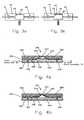
- Fig. 7is a top plan view of a portion of fluid delivery device
- Fig. 8is a sectional view of the portion of the fluid delivery device taken along line 8 - - 8 of Fig. 7 ;
- Fig. 9is a sectional view of the portion of the fluid delivery device taken along line 9 - - 9 of Fig. 7 ;
- Fig. 10is a sectional view of the portion of the fluid delivery device taken along line 10 - - 10 of Fig. 7 ;
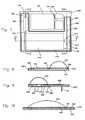
- Figs. 11 a and 11bare sectional views of the entire fluid delivery device of Fig. 7 , illustrating operation of the device;
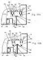
- Figs. 12a and 12bare sectional views of an embodiment of a valve constructed in accordance with the present disclosure, illustrating operation of the valve;
- Figs. 13a and 13bare sectional views of another embodiment of a valve constructed in accordance with the present disclosure, illustrating operation of the valve;
- Fig. 14is a sectional view of a further embodiment of a valve constructed in accordance with the present disclosure.
- Fig. 15is a sectional view of another embodiment of a valve constructed in accordance with the present disclosure.
- Fig. 16is a sectional view of another embodiment of a dispenser constructed in accordance with the present invention.
- Figs. 17a and 17bare sectional views of another embodiment of a dispenser constructed in accordance with the present disclosure, illustrating operation of the dispenser;
- Figs. 18a and 18bare sectional views of another embodiment of a dispenser constructed in accordance with the present disclosure, illustrating operation of the dispenser;
- Figs. 19a and 19bare sectional views of another embodiment of a dispenser constructed in accordance with the present disclosure, illustrating operation of the dispenser;
- Figs. 20a and 20bare sectional views of a further embodiment of a dispenser constructed in accordance with the present disclosure, illustrating operation of the dispenser;
- Figs. 21a, 21b and 21care sectional views of another embodiment of a dispenser constructed in accordance with the present disclosure, illustrating operation of the dispenser;
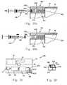
- Figs. 22a and 22bare sectional views of a portion of another embodiment of a fluid delivery device including a priming mechanism constructed in accordance with the present disclosure, and illustrating operation of the priming mechanism;
- Figs. 23a and 23bare sectional views of a portion of an additional embodiment of a fluid delivery device including a priming mechanism constructed in accordance with the present disclosure, and illustrating operation of the priming mechanism;
- Fig. 24is a schematic illustration of a further embodiment of a fluid delivery device constructed in accordance with the present disclosure.
- Fig. 25is a schematic illustration of another embodiment of a fluid delivery device and a remote control device constructed in accordance with the present disclosure
- Fig. 26is a schematic illustration of an additional embodiment of a fluid delivery device constructed in accordance with the present disclosure.
- Fig. 27is a schematic illustration of a further embodiment of a fluid delivery device constructed in accordance with the present disclosure.
- Fig. 28is a schematic illustration of a further embodiment of a fluid delivery device constructed in accordance with the present disclosure.
- Figs. 29a through 29dare sectional views of an embodiment of a fill port constructed in accordance with the present disclosure, and illustrating operation of the fill port;
- Figs. 30a and 30bare sectional views of another embodiment of a fill port constructed in accordance with the present disclosure, and illustrating operation of the fill port;
- Fig. 31is a top sectional view of another device constructed in accordance with the present invention.
- Fig. 32is a side elevation view, partially cut away, of the device of Fig. 31 .
- a fluid delivery device 10according to a preferred embodiment of the present invention.
- the types of liquids that can be delivered by the fluid delivery device of the present inventioninclude, but are not limited to, insulin, antibiotics, nutritional fluids, total parenteral nutrition or TPN, analgesics, morphine, hormones or hormonal drugs, gene therapy drugs, anticoagulants, analgesics, cardiovascular medications, AZT or chemotherapeutics.
- the types of medical conditions that the fluid delivery device of the present invention might be used to treatinclude, but are not limited to, diabetes, cardiovascular disease, pain, chronic pain, cancer, AIDS, neurological diseases, Alzheimer's Disease, ALS, Hepatitis, Parkinson's Disease or spasticity.
- the device 10generally includes an exit port assembly 70 adapted to connect to a transcutaneous patient access tool such as a needle, a dispenser 40 for causing fluid from a reservoir 30 to flow to the exit port assembly 70, and a processor or electronic microcontroller (hereinafter referred to as the "local" processor) 50 connected to the dispenser 40.
- a transcutaneous patient access toolsuch as a needle
- a dispenser 40for causing fluid from a reservoir 30 to flow to the exit port assembly 70
- a processor or electronic microcontrollerhereinafter referred to as the "local" processor
- the local processor 50is programmed to cause a flow of fluid to the exit port assembly 70 based on flow instructions from a separate, remote control device 100, an example of which is shown in Fig. 1 .
- the fluid delivery device 10further includes a wireless receiver 60 connected to the local processor 50 for receiving the flow instructions from the separate, remote control device 100 and delivering the flow instructions to the local processor.
- the device 10also includes a housing 20 containing the exit port assembly 70, the reservoir 30, the dispenser 40, the local processor 50, and the wireless receiver 60.
- the housing 20is free of user input components for providing flow instructions to the local processor 50, such as electromechanical switches or buttons on an outer surface 21 of the housing, or interfaces otherwise accessible to a user to adjust the programmed flow rate through the local processor 50.
- user input componentssuch as electromechanical switches or buttons on an outer surface 21 of the housing, or interfaces otherwise accessible to a user to adjust the programmed flow rate through the local processor 50.
- the lack of user input componentsallows the size, complexity and costs of the device 10 to be substantially reduced so that the device 10 lends itself to being small and disposable in nature.
- the fluid delivery device 10includes the wireless communication element, or receiver 60 for receiving the user inputs from the separate, remote control device 100 of Fig. 1 .
- Signalscan be sent via a communication element (not shown) of the remote control device 100, which can include or be connected to an antenna 130, shown in Fig. 1 as being external to the device 100.
- the remote control device 100has user input components, including an array of electromechanical switches, such as the membrane keypad 120 shown.
- the control device 100also includes user output components, including a visual display, such as a liquid crystal display (LCD) 110.
- a visual displaysuch as a liquid crystal display (LCD) 110.
- the control devicecan be provided with a touch screen for both user input and output.
- the remote control device 100has its own processor (hereinafter referred to as the "remote" processor) connected to the membrane keypad 120 and the LCD 110.
- the remote processorreceives the user inputs from the membrane keypad 120 and provides "flow" instructions for transmission to the fluid delivery device 10, and provides information to the LCD 110. Since the remote control device 100 also includes a visual display 110, the fluid delivery device 10 can be void of an information screen, further reducing the size, complexity and costs of the device 10.
- the communication element 60 of the device 10preferably receives electronic communication from the remote control device 100 using radio frequency or other wireless communication standards and protocols.
- the communication element 60is a two-way communication element, including a receiver and a transmitter, for allowing the fluid delivery device 10 to send information back to the remote control device 100.
- the remote control device 100also includes an integral communication element 60 comprising a receiver and a transmitter, for allowing the remote control device 100 to receive the information sent by the fluid delivery device 10.
- the local processor 50 of the device 10contains all the computer programs and electronic circuitry needed to allow a user to program the desired flow patterns and adjust the program as necessary.
- Such circuitrycan include one or more microprocessors, digital and analog integrated circuits, resistors, capacitors, transistors and other semiconductors and other electronic components known to those skilled in the art.
- the local processor 50also includes programming, electronic circuitry and memory to properly activate the dispenser 40 at the needed time intervals.
- the device 10includes a power supply 80, such as a battery or capacitor, for supplying power to the local processor 50.
- the power supply 80is preferably integrated into the fluid delivery device 10, but can be provided as replaceable, e.g., a replaceable battery.
- the devicecan include sensors or transducers such as a reservoir volume transducer or a reservoir pressure transducer, for transmitting information to the local processor 50 to indicate how and when to activate the dispenser 40, or to indicate other parameters determining flow, pump flowpath prime condition, blockage in flowpath, contact sensors, rotary motion or other motion indicators, as well as conditions such as the reservoir 30 being empty or leaking, or the dispensing of too much or too little fluid from the reservoir, etc.
- sensors or transducerssuch as a reservoir volume transducer or a reservoir pressure transducer, for transmitting information to the local processor 50 to indicate how and when to activate the dispenser 40, or to indicate other parameters determining flow, pump flowpath prime condition, blockage in flowpath, contact sensors, rotary motion or other motion indicators, as well as conditions such as the reservoir 30 being empty or leaking, or the dispensing of too much or too little fluid from the reservoir, etc.
- the volume of the reservoir 30is chosen to best suit the therapeutic application of the fluid delivery device 10 impacted by such factors as available concentrations of medicinal fluids to be delivered, acceptable times between refills or disposal of the fluid delivery device 10, size constraints and other factors.
- the reservoir 30may be prefilled by the device manufacturer or a cooperating drug manufacturer, or may include external filling means, such as a fill port having needle insertion septum or a Luer connector, for example.
- the device 10can be provided with a removable reservoir.
- the exit port assembly 70can include elements to penetrate the skin of the patient, or can be adapted to connect to a standard infusion device that includes transcutaneous delivery means.
- a needle connection tubing terminating in a skin penetrating cannulacan be provided as an integral part of the exit port assembly 70, for example, with the skin penetrating cannula comprising a rigid member, such as a needle.
- the exit port assembly 70can be provided with a Luer connector for connecting to a standard infusion device including a skin penetrating cannula, such as a rigid needle.
- the exit port assembly 70includes injection means, such as a spring driven mechanism, to assist in penetrating the skin with the skin penetrating cannula.
- the cannulais a flexible tube
- a rigid penetrator within the lumen of the tubeis driven through the skin by the injection means, and withdrawn leaving the soft cannula in place, such as in the subcutaneous tissue of the patient or other internal site.
- the injection meansmay be integral to the device 10, or removable soon after transcutaneous penetration.
- the exit port assembly 70can also be provided with a removable plug (not shown) for preventing leakage during storage and shipment if pre-filled, and during priming if filled by user, and prior to use.
- the device 10can also be provided with an adhesive layer on the outer surface of the housing 20 for securing the device 10 directly to the skin of a patient, as shown in Fig. 1 .
- the adhesive layeris preferably provided in a continuous ring encircling the exit port assembly 70 in order to provide a protective seal around the penetrated skin.
- the housing 20can be made from flexible material, or can be provided with flexible hinged sections that allow the fluid delivery device 10 to flex during patient movement to prevent detachment and aid in patient comfort.
- the dispenser 40is connected in fluid communication with the reservoir 30, as shown in Fig. 2 .
- the dispenser 40can include an inlet valve 41 connected to the reservoir, an outlet valve 42 connected to the exit port assembly 70, and an accumulator 43 connected between the inlet valve and the outlet valve, as shown in the exemplary embodiment of Figs. 3a and 3b . Since the fluid in the reservoir 30 is maintained at a pressure above atmospheric pressure, opening of the inlet valve 41 allows the accumulator 43 to fill to the reservoir pressure, after which the inlet valve is 41 is closed.
- the outlet valve 42can be opened to dispense fluid to the exit port assembly 70, which is at the pressure of the patient, or atmospheric pressure.
- the accumulator 43will then be at atmospheric pressure, and the outlet valve 42 can be closed, ready for another repeat cycle.
- the dispenser 40 of the exemplary embodiment of Figs. 3a and 3bdoes not create a driving or pumping force on the fluid passing therethrough, but rather acts as a metering device, allowing pulses of fluid to pass from the pressurized reservoir 30, through the dispenser 40, to the exit port assembly 70 at atmospheric pressure.
- the inlet valve 41 and the outlet valve 42 of the dispenser 40are controlled by the local processor 50, which includes electronic programming, controls and circuitry to allow sophisticated fluid delivery programming and control of the dispenser 40.
- Fig. 3 ashows the dispenser 40 with the accumulator 43 at atmospheric pressure.
- An accumulator membrane 44is shown in a non-distended state, caused by atmospheric pressure only.
- Inlet valve 41is closed, and outlet valve 42 may be open or closed, but must have been opened since the last time inlet valve 41 was opened.
- Fig. 3bshows the condition where outlet valve 42 is closed, and inlet valve 41 has been opened. Because of the elevated pressure of the fluid from the reservoir 30, the accumulator membrane 44 is distended, thus increasing the volume of accumulator 43 by an accumulator volume 45. After the inlet valve 41 is closed, the outlet valve 42 can be opened, to dispense the accumulator volume 45 and allow the accumulator membrane 44 to retract to the position shown in Fig. 3a .
- the inlet valve 41 and the outlet valve 42 of the dispenser 40 and the local processor 50are designed to prevent both valves from being opened at the same time, precluding the reservoir 30 to ever flow directly to the exit port assembly 70.
- the prevention of both valves opening at the same timeis critical and can be accomplished via mechanical means, electrical means, or both.
- the preventioncan be accomplished in the dispenser 40 design, the local processor 50 design, or both.
- the dispenser 40 shown in Figs. 3a and 3bdispenses finite pulses of fluid volume, called pulse volume (PV), with each activation.
- the PVis determined by the properties, materials and construction of the accumulator 43 and the accumulator membrane 44. PV's delivered by infusion devices are typically chosen to be small relative to what would be considered a clinically significant volume. For insulin applications at a concentration of 100 units per ml, a PV of less than 2 microliter, and typically 0.5 microliter, is appropriate. If the fluid delivery device 10 is programmed via the remote control device 100 to deliver 2 units an hour, the dispenser will deliver 40 pulses an hour, or a pulse every 1.5 minutes. Such pulsitile flow is considered continuous if the PV is small enough. Other drugs or concentrations may permit a much larger PV. Various flow rates are achieved by adjusting the time between pulses. To give a fixed volume or bolus, multiple pulses are given in rapid succession until the bolus volume is reached.
- the PVmay not always be constant enough to be within the accuracy requirements of the fluid delivery device 10.
- One factor impacting the PVis the pressure of the reservoir 30.
- the fluid delivery device 10may include means for monitoring reservoir 30 pressure and adjust the timing between pulses to achieve the desire flow pattern. An example of such compensation would be to decrease time between pulses as the reservoir 30 pressure decreases to maintain the programmed flow rate.
- An alternative to monitoring reservoir 30 pressureis monitoring the volume of the reservoir 30. Each time a pulse or series of pulses are delivered, a measurement of reservoir 30 volume can indicate whether a proper amount of fluid has been delivered, both for individual pulses and cumulative pulses. The system could also be designed to compensate fluid flow as errors are detected.
- the present inventionprovides an improved dispenser 240 for use with the fluid delivery device 10 of Figs. 1 and 2 .
- Operation of the dispenser 240 of Figs. 4a and 4bis similar to operation of the dispenser 40 of Figs. 3a and 3b .
- some elements of the dispenser 240 of Figs. 4a and 4bare similar to the dispenser 40 of Figs. 3a and 3b such that similar elements have the same reference numeral preceded by a "2".
- the dispenser 240 of Figs. 4a and 4bincludes at least two laminated layers 252, 254 of material defining a passageway 250 for connection to the exit port assembly 70, and an expandable accumulator 243 in fluid communication with the passageway 250 for controlling fluid flow from the reservoir 30 to the exit port assembly 70.
- the laminated constructionprovides many benefits including, but not limited to, simplifying the design and manufacturing of the dispenser 240, and further reducing the size, complexity and costs of the dispenser 240.
- the dispenser 240 of the present inventiontherefore, lends itself to being small and disposable in nature.
- the layers of the dispenser 240include a first layer 252 and a second layer 254 received against the first layer. At least one of the second and the first layers 252, 254 includes a surface groove between the layers which defines the passageway 250 connected to the exit port assembly 70.
- the second layer 254includes an opening 246 in fluid communication with the passageway 250.
- the layers 252, 254also include a resilient diaphragm 244 received on the second layer 254 covering the opening, and a third layer 256 received over the diaphragm 244 on the second layer 254.
- the third layer 256has a pulse chamber 245 over the diaphragm 244 and in alignment with the opening 246 of the second layer 254, and a relief port 247 in fluid communication with the pulse chamber 245.
- Fig. 4ashows the dispenser 240 with the accumulator 243 at atmospheric pressure with the resilient diaphragm 244 in a non-distended state.
- Inlet valve 241is closed, and outlet valve 242 may be open or closed, but must have been opened since the last time the inlet valve 241 was opened.
- Fig. 4bshows the condition wherein the outlet valve 242 is closed, and the inlet valve 241 has been opened. Because of the elevated pressure of the fluid from the reservoir 30, the fluid expands the resilient diaphragm 244 into the pulse chamber 245 (with the relief port 247 allowing evacuation of the pulse chamber 245), thus increasing the volume of the accumulator 243 by about a volume of the pulse chamber 245.
- the outlet valve 242can be opened, to dispense the accumulator volume 245 and allow the resilient diaphragm 244 to return to the position shown in Fig. 4a .
- the laminated construction of the dispenser 240allows most manufacturing tolerances of the dispenser 240 to be lowered, and the manufacturing process to be simplified, without effecting the performance and reliability of the dispenser 240.
- High tolerancesare required for only the volume of the pulse chamber 245 and the resilience of the diaphragm 244, since those dimensions affect the resulting PV produced by the dispenser 240.
- Other dimensions and properties of the dispenser 240can be relatively relaxed to reduce the costs of the dispenser.
- at least one of the second and the third layers 254, 256defines a recess 260 receiving the diaphragm 244.
- the recess 260has a depth about equal to a thickness of the diaphragm 244 such that the diaphragm is secured in a substantially fluid-tight manner between the second and the third layers 254, 256.
- a length and a width of the recess 260are greater than a length and a width of the diaphragm 244 in order to decrease the required manufacturing tolerances of the dispenser 240.
- Manufacturing the dispenser 240is preferably a "drop down" process.
- First the layers 252, 254, 256are individually formed with the necessary openings, groove, and recesses.
- the first layer 252is then laid down and the valves 241, 242 are dropped into recesses (not shown) in the first layer and correctly positioned within the groove 250.
- the second layer 254is placed on the first layer 252, and the diaphragm 244 is placed in the recess 260 of the second layer.
- the third layer 256is positioned over the diaphragm 244 and the second layer 254.
- the layers 252, 254, 256can be made from a suitably strong and rigid material such as plastic or stainless steel, and can be secured together in a suitable manner, such as with adhesives or by welding.
- the diaphragm 244can be made from a suitably expandable yet resilient material, such as rubber or a synthetic rubber.
- a first layer 252defines the passageway 250 connected to the exit port assembly 70 and an opening 246 in fluid communication with the passageway.
- the resilient diaphragm 244is received on the first layer 252 covering the opening 246, and a second layer 254 is received over the diaphragm 244 on the first layer.
- the second layer 254has a pulse chamber 245 over the diaphragm 244 and in alignment with the opening 246 of the first layer 252, and a relief port 247 in fluid communication with the pulse chamber 245.
- a third layer 256is received on the second layer 254 and defines a relief chamber 248 in fluid communication with the relief port 247 of the second layer 252.
- the relief chamber 248allows the pulse chamber 245 to be evacuated upon expansion of the diaphragm 244, yet keeps the pulse chamber sealed and the relief port protected.
- the relief chamber 248can also be pressurized to further regulate the PV produced by the dispenser 270.
- Fig. 6shows another dispenser 280 according to a preferred embodiment of the present invention.
- the dispenser 280is similar to the dispenser 240 of Figs. 4a and 4b such that similar elements have the same reference numerals.
- the dispenser 280further includes a compression spring 282 biasing the diaphragm 244 away from the pulse chamber 245. The strength of the spring is set along with the volume of the pulse chamber 245 and the resilience of the diaphragm 244, to provide a predetermined PV.
- Figs. 7 through 11a and 11bshow an entire fluid delivery device 290 incorporating the laminated construction provided by the present invention.
- the device 290is similar to the device of Figs. 1 and 2 , but includes a first layer 252 and a resilient diaphragm 288 received on a surface of the first layer.
- the surface of the layer 252has a recess and a groove extending from the recess to the exit port assembly 70, such that the recess of the layer 252 and a portion 244 of the diaphragm 288 define the expandable accumulator 243, and the groove of the layer 252 and the diaphragm 288 define the passageway 250 connected to the exit port assembly 70.
- the surface of the first layer 252also has a valve seat 292 in the groove and an occlusion sensor recess 294 in the groove, between the valve seat 292 and the exit port assembly 70.
- the surface of the first layer 252further includes a reservoir recess 296, a groove 298 extending between the reservoir and the accumulator 243, and a valve seat 291 in the groove 298.
- the surface of the first layer 252includes a bubble removal bay 300, a groove 302 extending between the bubble removal bay 300 and the reservoir recess 296, a fill port recess 304, and a groove 298 extending between the fill port recess 304 and the bubble removal bay 300.
- the diaphragm 288 and the first layer 252therefore, define an occlusion sensor chamber 294, the reservoir 296, a bubble removal chamber 300, and connecting passageways 298, 302, 306.
- the diaphragm 288is secured to the surface of the layer 252 in a fluid-tight manner, such as with an adhesive.
- the portion 244 of the diaphragm 288expands when the reservoir 296 is filled in order to pressurize the fluid within the reservoir.
- a switch 308is positioned in the chamber 294 to monitor for an occlusion, as shown in Fig. 9 .
- the switch 308is arranged such that when that portion of the diaphragm 288 over the chamber 294 expands, the switch closes to indicate an occlusion.
- a strain gagecan be attached to that portion of the diaphragm 288 over the chamber 294, or a pressure sensor can be positioned in the chamber 294 to monitor for an occlusion.
- the diaphragm 288can be provided with consistent properties, such as resilience, throughout, or can include inconsistent properties.
- the portion 244 of the diaphragm 288 over the reservoir recess 296can be provided with a greater thickness to increase the resilience of that portion, while the thickness of the diaphragm 288 over the valve seats 291, 292 may be made thinner to decrease the resilience of those portions.
- the diaphragm 288can be made from a material that allows gas to pass through yet prevents liquid from passing through, such that the diaphragm 288 also acts as a bubble removal filter.
- the diaphragm 288can be provided with coatings.
- surfaces of the diaphragm 288 in contact with flow pathscan be coated with material that promotes flow and avoids precipitation (such as insulin crystallization).
- the diaphragm 288can also be coated with lines of conductive material, for example, to support transmission of electrical signals between the local processor and other components of the device.
- the first layer 252also defines recesses 310, 312, 314, which are not covered by the diaphragm 288, for other components of the device including the local processor 50, the wireless communication unit 60 and the battery 80.
- Figs. 11a and 11bshow a cover 316 attached to the first layer 252 to complete the housing 20 of the fluid deliver device 290.
- the cover 316contains the power source 80, the wireless communication unit 60 and the local processor 50 of the device 290.
- the cover 316also includes the inlet and the outlet valves 241, 242 aligned over the valve seats 291, 292 of the first layer 252.
- the valves 241, 242 and the accumulator 243comprise the dispenser 320 for use with the pressurized reservoir 296.
- the cover 316also provides an enclosed space that allows for expansion of the diaphragm portion 244 over the reservoir 296.
- Figs. 12a and 12bshow a valve 330 for use as part of a laminated dispenser or part of a laminated fluid delivery device.
- the valve 330can comprise the inlet valve of the dispenser controlling flow from a reservoir into the accumulator.
- the valve 330is part of a passageway 250 formed from first and second layers 252, 254, wherein the second layer 254 includes an opening 332 communicating with the passageway.
- the valve 330includes a layer of resilient fluid-tight material 334 covering the opening, and a layer of piezoelectric material 336 covering the layer of resilient fluid-tight material.
- the layers of resilient fluid-tight material 334 and piezoelectric material 336are arranged such that upon contracting, the layer of piezoelectric material 336 forces the layer of resilient fluid-tight material 334 into the opening 332 of the passageway 250 and substantially closes the passageway, as shown in Fig. 12a .
- the piezoelectric material 336includes a wire 338 for connection to a power source (not shown). When power is applied to the piezoelectric material 336, the piezoelectric material straightens out, thereby opening the passageway 250, as shown in Fig. 12b .
- the resilient fluid-tight material 334can be provided as part of the resilient diaphragm forming the accumulator of the dispenser.
- the piezoelectric material 336is normally curved when de-energized, and deforms to a straight geometry when energized, such that the passageway 250 is normally closed.
- Figs. 13a and 13bshow another valve 340 .
- the valve 340is similar to the valve 330 of Figs. 12a and 12b such that similar elements have the same reference numerals.
- the valve 340 of Figs. 13a and 13bfurther includes an opening 332 in the first layer 252, and a layer of resilient fluid-tight material 334 covering the opening in the first layer, and a layer of piezoelectric material 336 covering the layer of resilient fluid-tight material.
- the layers of piezoelectric material 336react together to close the passageway 250 when de-energized ( Fig. 13a ), and to open the passageway when energized ( Fig. 13b ).
- An alternative embodimentcan include a tubular layer of resilient fluid-tight material and a tubular layer of piezoelectric material positioned over an annular opening in the passageway.
- a valve assembly 350is shown in Fig. 14 .
- the valve assembly 350is shown as part of a laminated dispenser having first, second and third layers 252, 254, 256.
- the first layer 252defines the pulse chamber 245, the evacuation port 247, and the enlarged recess 260 receiving the diaphragm 244 over the pulse chamber to form the accumulator 243.
- the second layer 254defines the groove for the passageway 250, an opening 246 communicating with the groove in alignment with the pulse chamber 245, and a recess 351 on the surface of the second layer 254 in alignment with the opening.
- the third layer 256defines a valve assembly chamber 352 facing the second layer 254 in alignment with the recess 351 of the second layer.
- the valve assembly 350includes a valve member 354, springs 356 and a fluid resistant cover 358.
- the valve member 354is received in the valve assembly chamber 352 of the third layer 256 and includes a bar 360 extending parallel with the passageway 250 and pivotally mounted on the third layer about a pivot point 364 aligned with the accumulator 243.
- An inlet valve 361 and an outlet valve 362extend from the bar 360 into the passageway 250 on opposite sides of the pivot point 364 (and on opposite sides of the accumulator 243).
- the springs 356are positioned between the ends of the bar 360 and the third layer 256 to bias each end towards the second layer 254.
- the fluid resistant cover 358is received in the recess 351 of the second layer 254 (the recess preferably being oversized with respect to the cover to reduce manufacturing tolerances), and provides a water-tight seal between the passageway 250 and the valve assembly 350.
- the valve assembly 350also includes an actuator for causing the valve member 354 to pivot.
- the actuatorcan comprise a rotary motor, a linear motor, a clock spring, and piezoelectric material, for example. Many different types of actuators can be used for causing the valve member 354 to pivot when desired.
- the pivoting valve assembly 354provides the benefit of the valves 361, 362 alternatively blocking the passageway 250 at all times, such that unregulated flow to the exit port assembly is not permitted.
- the valve assembly 350also utilizes "drop down" construction, wherein all elements of the valve assembly are assembled from above the second layer 254, to simplify manufacturing.
- valve assembly 370is shown in Fig. 15 .
- the valve assembly 370is shown as part of a laminated dispenser having first and second layers 252, 254, with the passageway 250 defined between the layers.
- the laminated layers 252, 254also define a bore 372 bisecting the passageway 250 and receiving the valve assembly 370.
- the valve assembly 370includes a valve member 374 movably received in the bore 372 and including an opening 376, and a spring 378 biasing the valve member such that the opening 376 of the valve member is normally offset from the passageway 250 and the passageway is blocked by the valve member 374.
- the assembly 370also includes an actuator 380 for moving the valve member 374 upon being actuated such that the opening 376 of the valve member 374 aligns with the passageway 250 to thereby allow flow through the passageway.
- the actuatorcomprises a gas generator 380 for pressurizing the bore 372 upon being actuated.
- the gas generator 380is mounted in a plug 382 fitted in the second layer 254 and having a gas release port 384 communicating with the bore 372.
- the valve assembly 370also utilizes "drop down" construction, wherein all elements of the valve assembly can be assembled from above the second layer 254, to simplify manufacturing.
- the actuated gas generator 380pressurizes the bore 372 above the valve member 374 and forces the valve member to move against the spring 378, so that the opening 376 aligns with the passageway 250 and opens the passageway.
- the gas release port 384allows a predetermined rate of gas to exit the bore 372 in order to limit the total pressure in the bore and allow a controlled decay of pressure.
- the valve assembly 370is positioned near the exit port assembly of a fluid delivery device to limit the useable life of the fluid delivery device.
- the fluid delivery devicecan include automatic or manual means for actuating the gas generator 380 upon the device being secured to a patient's skin, and the gas generator can be provided with enough fuel to maintain the valve member 374 open for three days.
- valve member 374closes and the fluid delivery device must be replaced with a new device.
- the valve 370can also be used to pulse fluid as long as the gas generation rate of the gas generator 380 and the gas release rate of the gas release port 384 have time constants slightly smaller than the maximum pulse rate.
- the dispenser 390is for use with a pressurized reservoir and includes an inlet valve 241, an accumulator 243 and an outlet valve 242.
- the dispenserincludes three layers 252, 254, 256.
- the second and the first layers 252, 254define the passageway 250 connected to the exit port assembly, and the second layer 254 defines the pulse chamber 245 communicating with the passageway.
- a piston 392is slidingly received in the pulse chamber 245, and a substantially fluid tight seal is provided between the piston and the wall of the pulse chamber.
- the piston 392in effect comprises the expandable membrane of the accumulator 243.
- the third layer 256is received on the second layer 254 and closes the pulse chamber 245, and springs 394 are positioned between the third layer and the piston 392 and bias the piston away from the third layer.
- the outlet valve 242is closed and the inlet valve 241 is opened to allow pressurized fluid from the reservoir to move the piston 392 against the springs 392 and into the pulse chamber 245 to expand the accumulator 243 by the predetermined pulse volume.
- the inlet valve 241is closed and the outlet valve 242 is opened such that the biased piston 392 can force the pulse volume of liquid to the exit port assembly.
- the dispenser 400is for use with a non-pressurized reservoir (not shown) and, therefore, is designed to act as a pump instead of simply a regulator.
- the dispenser 400includes an inlet valve 402, an accumulator 404, and an outlet valve 406.
- the valves 402, 406comprise one-way valves, such as duckbill valves, and the accumulator 404 is an "active" accumulator, as opposed to the "passive" accumulators used in the previously described dispensers.
- the second and the first layers 252, 254 of the dispenser 400define the passageway 250 connected between the reservoir and the exit port assembly, and the second layer 254 defines a bore 408 communicating with the passageway 250.
- a piston 410is slidingly received in the bore 408 and acts as the expandable membrane of the accumulator 404.
- the dispenser 400also includes an actuator 412 for moving the piston 410 in the bore 408 to draw fluid from the reservoir through the inlet valve 402 (the one-way outlet valve 406 prevents fluid from being draw though the outlet valve 406) and expel liquid through the outlet valve 406 to the exit port assembly (the one-way inlet valve 402 prevents fluid from being expelled though the inlet valve 402).
- the actuatorcomprises a magnetic coil 412 received in an annular groove provided in the second layer 254, coaxial with the piston 410, which is made from magnetic material.
- a plug 414seals the piston 410 and the coil 412 in the second layer 254, such that the portion of the bore 408 between the piston 410 and the plug 414 comprises the pulse chamber of the accumulator 404.
- the dispenser 400includes a coiled compression spring 416 positioned between the plug 414 and the piston 410 biasing the piston towards the passageway 250.
- the coil 412is arranged to bias the piston 410 against the spring 416 upon being energized.
- the coil 412is energized such that movement of the piston 410 expands the accumulator 404, and draws fluid from the reservoir, through the one-way inlet valve 402 and into the bore 408, as shown in Fig. 17a .
- the one-way inlet valve 402closes when the accumulator 404 is fully expanded.
- the coil 412is de-energized, so that the spring 416 is allowed to push the piston 410 back towards the passageway 250, compress the accumulator 404, and expel the liquid through the one-way outlet valve 406 to the exit port assembly, as shown in Fig. 17b .
- Figs. 18a and 18bshow another laminated dispenser 420 and which operates in a manner similar to the dispenser 400 of Figs. 17a and 17b .
- the dispenser 420includes a one-way inlet valve 402, an "active" accumulator 424, and a one-way outlet valve 406.
- the second and the first layers 252, 254 of the dispenser 420define the passageway 250 connected between the reservoir (not shown) and the exit port assembly (not shown).
- the accumulator 424includes a pulse chamber 426 formed in a surface of the second layer 254 facing away from the first layer 252, and an opening 428 providing fluid communication between the pulse chamber 426 and the passageway 250.
- a resilient diaphragm 430is received on the second layer 254 and covering the pulse chamber 426 in a fluid-tight manner.
- the dispenser 420also includes an actuator 432 for pushing the diaphragm 430 into the pulse chamber 426 to reduce the volume of the accumulator 424 and produce a pulse volume.
- the actuatorcomprises a rotatable cam 432 and a motor (not shown) or other rotational device for rotating the cam.
- the cam 432is rotated away from the diaphragm 430 such that the diaphragm expands the accumulator 424, and draws fluid from the reservoir, through the inlet valve 402 and into the pulse chamber 426, as shown in Fig. 18a .
- the inlet valve 402closes when the accumulator 424 is fully expanded.
- the cam 432is rotated back into the diaphragm 430, so that the diaphragm compresses the pulse chamber 426 and expels the liquid through the outlet valve 406 to the exit port assembly, as shown in Fig. 18b .
- the dispenser 440is for use with a non-pressurized reservoir (not shown) and, therefore, is designed to act as a pump instead of simply a regulator.
- the dispenser 440includes a plurality of "active" accumulators 442 and no inlet valve or outlet valve.
- the accumulators 442are arranged successively with respect to the passageway 250 and operate one after another such that the dispenser 440 operates as a linear peristaltic pump.
- the second and the first layers 252, 254 of the dispenser 440define the passageway 250 connected between the reservoir and the exit port assembly.
- the resilient diaphragm 444is positioned between the second layer 254 and the third layer 256 in a liquid-tight manner.
- the second layer 254defines a pulse chamber 446 communicating with the passageway 250
- the third layer 256defines a bore 448 aligned with the pulse chamber.
- the dispenser 440also includes actuators for compressing the pulse chambers 446 and expelling pulse volumes of liquid towards the exit port assembly.
- the actuatorscomprise pistons 450 made from magnetic material and slidingly received in the bores 448, and magnetic coils 452 received in annular grooves provided in the third layer 256, coaxial with the pistons 450.
- Each coil 452is arranged such that, upon being energized, the coil 452 forces the piston 450 against the diaphragm 444 to collapse the pulse chamber 446 and expel a pulse volume of fluid from the accumulator 442 into the passageway 250.
- the coil 452Upon being de-energized, the coil 452 releases the piston 450 and allows the diaphragm 444 to push the piston back, and draw a pulse volume of fluid into the pulse chamber 446.
- the coils 452are successively energized and de-energized so that fluid is drawn from the reservoir, expelled and drawn successively into the accumulators 442, and expelled to the exit port assembly.
- at least one of the pistons 450is always in a closed position to occlude the fluid path and prevent the free flow of fluid through the passageway to the exit port assembly.
- the pistons 450can be biased closed, with a spring, and the coils 452 arranged to pull the pistons away from the passageway when energized.
- Figs. 20a and 20bshow another laminated dispenser 460 .
- the dispenser 460is similar to the dispenser 440 of Figs. 19a and 19b , but includes a fourth layer 258 defining bores 462 aligned with the bores 448 of the third layer 256.
- the actuatorscomprise the pistons 450, and gas generators 464 received in the bores 462 of the fourth layer 258.
- the gas generators 464pressurize the bores 448, 462 and biasing the piston 450 against the diaphragm 444 upon being actuated.
- the fourth layer 258also includes gas release ports 466 communicating with the bores 462.
- a further embodiment of a laminated dispenser 470is shown.
- the dispenser 470is also for use with a non-pressurized reservoir and acts as a pump instead of simply a regulator.
- the dispenser 470includes a plurality of "active" accumulators 472 and no inlet valve or outlet valve.
- the accumulators 472are arranged successively with respect to the passageway 250 and operate one after another such that the dispenser 470 operates as a linear peristaltic pump.
- the dispenser 470includes a first layer 252 having a recess 476, with a diaphragm 474 positioned against the surface of the first layer 252.
- the second layer 254is received against the diaphragm 474 and includes a surface defining a groove, such that the diaphragm and the groove define the passageway 250 connecting the reservoir to the exit port assembly.
- Each accumulator 472includes an actuator 478.
- the actuators 478are successively positioned with respect to the passageway 250 within the recess 476 of the first layer 252.
- the actuators 478are arranged to push the diaphragm 474 towards the second layer 254 upon being actuated.
- the portion of the recess 476 above the diaphragm 474comprises the pulse chambers of the accumulators 472.
- the actuatorscomprise segments of piezoelectric material 478.
- Each segment 478is mounted and arranged such that, when de-energized, the segment 478 normally assumes a curved geometry to push the diaphragm 474 towards the second layer, and when energized, deforms to a straight geometry to allow the diaphragm to return to its original position.
- all of the piezoelectric elements 478are normally in a curved state when de-energized, to occlude the passageway 250 and prevent the free flow of fluid through the passageway to the exit port assembly.
- the present disclosurealso provides a priming mechanism 500 for simultaneously maintaining an inlet valve 502 and an outlet valve 504 of a dispenser 506 open, such that fluid can flow through the dispenser (also having an accumulator 507) to the exit port assembly 70 during filling of the reservoir 30. Priming ensures that the entire volume of the fluid delivery passages of the fluid delivery device are filled with fluid prior to operation, so that an accurate volume of fluid can be delivered by the device.
- the priming mechanism 500includes a pivotally movable first link 508 operatively connected to the inlet valve 502 such that the inlet valve is opened upon pivoting movement of the first link 508.
- a pivotally movable second link 510is operatively connected to the outlet valve 504 such that the outlet valve is opened upon pivoting movement of the second link.
- the priming mechanism 500also includes a movable priming rod 516 operatively connected to the first and the second links 508, 510 for pivoting the links upon movement of the rod 516.
- the inlet and the outlet valves 502, 504each include a valve member 512, 514 movable between open and closed positions.
- the first link 508extends between the first valve member 512 and the priming rod 516 and is pivotally movable about a pivot point 518 of the first link located between the valve member 512 and the priming rod.
- the second link 510extends between the second valve member 514 and the priming rod 516 and is pivotally movable about a pivot point 520 of the second link located between the valve member 514 and the priming rod.
- the priming rod 516is linearly movable to pivot the links 508, 510 and open the valve members 512, 514.
- the priming rod 516extends out of the housing 20 of the fluid delivery device, and is depressed into the housing 20 by a user to open the valves 502, 504 prior to filling the reservoir 30 through fill port 522.
- One-way valvessuch as duckbill valves 524, are positioned within the fill port 522 and a passageway 526 of the dispenser 506.
- Fig. 22bshows the priming rod 516 depressed into the housing 20 and the valves 502, 504 opened
- Fig. 22ashows the priming rod 516 extending out of the housing 20 and the valves 502, 504 closed.
- Figs. 23a and 23bshown another priming mechanism 530 .
- the mechanism 530is similar to the mechanism 500 of Figs. 22a and 22b such that similar elements have the same reference numerals.
- the mechanism 530further includes a collar 532 connected to the priming rod 516 and received in the fill port 522 of the device.
- the fill port 522is connected to the reservoir 30 and adapted for receiving a needle 534 for filling the reservoir.
- the collar 532is adapted to frictionally receive the needle 534 inserted into the fill port 522 so that the inserted needle causes movement of the collar 532 and the priming rod 516 and pivoting movement of the links 508, 510.
- the dispenser valves 502, 504are therefore opened and the device is primed automatically upon filling of the reservoir 30, shown in Fig. 23b .
- the present disclosurealso provides fluid delivery devices 10 having automatic priming systems 600, 610, 620.
- Each device 10is provided with an exit port assembly comprising an integrated transcutaneous patient access tool 670 having a known internal volume.
- the patient access toolis a needle 670. Because the volume to the tip of the needle 670 is known, the local processor 50 of the device 10 can be programmed to prime the needle 670 automatically.
- the local processor 50is programmed to instruct the dispenser 40 to deliver a volume of fluid to the needle 670 equal to the known internal volume of the needle 670.
- the remote controller 100is provided with a "PRIME" command for a user to select.
- a prime command button 111is shown provided on a touch screen 110 after an "INITIALIZE" command 112. When the prime command 111 is selected, the remote controller 100 communicates with the fluid delivery device 10 and instructs the local processor 50 to prime the needle 670.
- the fluid delivery device 610 of Fig. 25further includes a flow sensor 612 arranged to provide a signal to the local processor 50 indicative of the volume of fluid passing from the dispenser 40 to the needle 670.
- the local processor 50is programmed to prime the needle 670 by instructing the dispenser 40 to deliver fluid until the flow sensor 612 indicates to the local processor that a volume of fluid equal to the known internal volume of the needle 670 has been delivered to the needle.
- the local processor 50is also programmed to utilize the signals from the flow sensor 612 to monitor the needle 670 for occlusions once the needle has been primed.
- the device 620 of Fig. 26is similar to the device 600 of Fig. 24 , but further includes a fluid detector 622 positioned between the dispenser 40 and the needle 670 for providing a signal to the local processor 50 indicative of fluid passing into the needle 670.
- the local processor 50is programmed to prime the needle 670 by instructing the dispenser 40 to deliver fluid for a predetermined period and at a predetermined flow rate after receiving an initial indication from the fluid detector 622 that fluid has reached the fluid detector 622.
- the local processor 50can be programmed to provide a signal that air has been detected in the fluid path when the fluid detector 622 stops indicating the presence of fluid upon operation of the dispenser 40 and after the needle 670 has been primed.
- the disclosurealso provides embodiments 700, 710 of the fluid delivery device including gas removal filters 702 for removing gas (e.g., air) bubbles from fluid injected into the devices from a patient.
- gas removal filters 702are constructed of material that allows the passage of gas therethrough, yet prevents fluid from passing therethrough. Gas removal filters are available, for example, from Pall Corporation of East Hills, NY (www.pall.com).
- the gas removal filter 702is positioned between the reservoir 30 and the dispenser 40.
- the gas removal filter 702is positioned between a fill port 31 and the reservoir 30.
- the devicecan be provided with a reservoir made from gas removal material instead of having a separate gas removal filter.
- the present disclosuretherefore, also provides a "single-use" fill port 800 for allowing the reservoir 30 of the fluid device to be filled only once.
- the fill port 800includes a passageway 802 in fluid communication with the reservoir 30, a valve 804 positioned within the passageway and allowing one-way flow into the reservoir 30, and a removable needle insertion septum 806 sealing the passageway 802.
- the needle insertion septum 806may be constructed of a resealing elastomer such as silicone that allows a needle 150 to puncture the septum 806 to add fluid to the reservoir 30, yet provides a seal around the needle 150.
- the fill port 800includes a funnel 808 having a small open end 810 removably received in the passageway 802 and a large open end 812 receiving the septum 806.
- the fill port 800also includes a first wall 814 having an opening 816 removably receiving the large open end 812 of the funnel when the small open end 810 of the funnel 808 is removably received in the passageway 802, as shown in Figs. 29a and 29b .
- a second wall 818is spaced from the first wall 814 more than a thickness of the septum 806 and has an opening 820 sized to allow passage of a needle 150, but prevent passage of the septum 806, as shown in Figs. 29c and 29d .
- removal of the needle 150 from the fill port 800pulls the funnel 808 out of the passageway 802, and thus prevents further refills of the reservoir 30 through the fill port 800.
- Figs. 30a and 30bshow another fill port 850 .
- the fill port 850includes a first wall 852 having an opening 854 preventing passage of the septum 806, as shown in Fig. 30a , and a second wall 856 spaced from the first wall 852 at least about a thickness of the septum and having an opening 858 allowing passage of a needle 150.
- the second wall 856 and the opening of the second wall 858are adapted to allow passage of the septum 806 upon at least a predetermined force applied to the septum.
- the predetermined forceis less than a force required to pull a needle 150 out of the septum 806, such that a withdrawn needle 150 pulls the septum 806 out of the fill port 850, as shown in Fig. 30b .
- the present disclosurealso provides a fluid delivery device 900 which may be used with a device according to the present invention having multiple subcutaneous access tools 970.
- Each access tool 970is independently connected to the dispenser 40 through a passageway 972, and is initially retracted such that the passageway 972 is occluded.
- Each access tool 970is also independently deployable. Upon deployment of each access tool 970, the passageway 972 of the deployed tool is released to allow fluid flow through the deployed tool.
- each access toolincludes a rigid needle 974, as shown in Fig. 32 .
- the multiple, independently deployable needles 974beneficially extend the useful life of the fluid delivery device 900.
- a single needlesuch as an infusion needle or intravenous needle, should not remain deployed in a patient for more than three days, to minimize the chances for infection at the injection site through the skin of the patient.
- the present embodimenttherefore, increases the useable life of a single fluid delivery device 900 by providing the device with multiple, independently deployable needles 974. If the device is provided with three retractable needles 974, and each needle is used for the maximum allowable period of three days in accordance to CDC standards, for example, the life of the device 900 can be extended to nine days.
- the embodiment 900 of Fig. 31is provided with three needles 974, but can be provided with two needles or more than three needles, as desired and appropriate.
- each needle 974is manually deployable and includes a slidable lever 976 secured to the needle and extending out of the housing 20 of the device for patient access.
- the needle 974is shown retracted in Fig. 32 , with the passageway 972 occluded by an occlusion member 978 extending from the lever 976 and pinching the passageway 972 against a boss 980 extending from the housing wall 20.
- the patientsimply slides the lever 976 towards the skin to release the passageway 972 and inject the needle 974 into the skin.
- the devicecan also be provided with means for maintaining each of the needles 974 in an independent sterile condition prior to deployment, such as separate sealed membranes covering the needle opening in the housing 20 and that the needles puncture through during deployment.
Landscapes
- Health & Medical Sciences (AREA)
- Dermatology (AREA)
- Vascular Medicine (AREA)
- Engineering & Computer Science (AREA)
- Anesthesiology (AREA)
- Biomedical Technology (AREA)
- Heart & Thoracic Surgery (AREA)
- Hematology (AREA)
- Life Sciences & Earth Sciences (AREA)
- Animal Behavior & Ethology (AREA)
- General Health & Medical Sciences (AREA)
- Public Health (AREA)
- Veterinary Medicine (AREA)
- Infusion, Injection, And Reservoir Apparatuses (AREA)
- External Artificial Organs (AREA)
Abstract
Description
- The present invention relates generally to medical devices, systems and methods, and more particularly to small, low cost, portable infusion devices and methods that are useable to achieve precise, sophisticated, and programmable flow patterns for the delivery of therapeutic liquids to a mammalian patient.
- Today, there are numerous diseases and other physical ailments that are treated by various medicines including pharmaceuticals, nutritional formulas, biologically derived or active agents, hormonal and gene based material and other substances in both solid or liquid form. In the delivery of these medicines, it is often desirable to bypass the digestive system of a mammalian patient to avoid degradation of the active ingredients caused by the catalytic enzymes in the digestive tract and liver. Delivery of a medicine other than by way of the intestines is known as parenteral delivery. Parenteral delivery of various drugs in liquid form is often desired to enhance the effect of the substance being delivered, insuring that the unaltered medicine reaches its intended site at a significant concentration. Also, undesired side effects associated with other routes of delivery, such as systemic toxicity, can potentially be avoided.
- Often, a medicine may only be available in a liquid form, or the liquid version may have desirable characteristics that cannot be achieved with solid or pill form. Delivery of liquid medicines may best be accomplished by infusing directly into the cardiovascular system via veins or arteries, into the subcutaneous tissue or directly into organs, tumors, cavities, bones or other site specific locations within the body.
- Parenteral delivery of liquid medicines into the body is often accomplished by administering bolus injections using a needle and reservoir, or continuously by gravity driven dispensers or transdermal patch technologies. Bolus injections often imperfectly match the clinical needs of the patient, and usually require larger individual doses than are desired at the specific time they are given. Continuous delivery of medicine through gravity feed systems compromise the patient's mobility and lifestyle, and limit the therapy to simplistic flow rates and profiles. Transdermal patches have special requirements of the medicine being delivered, particularly as it relates to the molecular structure, and similar to gravity feed systems, the control of the drug administration is severely limited.
- Ambulatory infusion pumps have been developed for delivering liquid medicaments to a patient. These infusion devices have the ability to offer sophisticated fluid delivery profiles accomplishing bolus requirements, continuous infusion and variable flow rate delivery. These infusion capabilities usually result in better efficacy of the drug and therapy and less toxicity to the patient's system. An example of a use of an ambulatory infusion pump is for the delivery of insulin for the treatment of diabetes mellitus. These pumps can deliver insulin on a continuous basal basis as well as a bolus basis as is disclosed in
U.S. Patent 4,498,843 to Schneider et al. - The ambulatory pumps often work with a reservoir to contain the liquid medicine, such as a cartridge or reservoir, and use electro-mechanical pumping or metering technology to deliver the medication to the patient via tubing from the infusion device to a needle that is inserted transcutaneously, or through the skin of the patient. The devices allow control and programming via electromechanical buttons or switches located on the housing of the device, and accessed by the patient or clinician. The devices include visual feedback via text or graphic screens, such as liquid crystal displays known as LCD's, and may include alert or warning lights and audio or vibration signals and alarms. The device can be worn in a harness or pocket or strapped to the body of the patient.
- Currently available ambulatory infusion devices are expensive, difficult to program and prepare for infusion, and tend to be bulky, heavy and very fragile. Filling these devices can be difficult and require the patient to carry both the intended medication as well as filling accessories. The devices require specialized care, maintenance, and cleaning to assure proper functionality and safety for their intended long term use. Due to the high cost of existing devices, healthcare providers limit the patient populations approved to use the devices and therapies for which the devices can be used.
- Clearly, therefore, there was a need for a programmable and adjustable infusion system that is precise and reliable and can offer clinicians and patients a small, low cost, light weight, simple to use alternative for parenteral delivery of liquid medicines.
- In response, the applicant of the present application provided a small, low cost, light weight, easy to use device for delivering liquid medicines to a patient. The device, which is described in detail in co-pending
U.S. application serial No. 09/943,992, filed on August 31, 2001 - What is still desired are new and improved devices for delivering fluid to a patient. Preferably, the fluid delivery devices will be simple in design, and inexpensive and easy to manufacture, in order to further reduce the size, complexity and costs of the devices, such that the devices lend themselves to being small and disposable in nature.
EP0789146 discloses a microvalve equipped with an elastic diaphragm , the microvalve fabrication method, a micropump that uses the microvalve and its fabrication method and a device that uses the micropump. The micropump has a tank. A tube is connected to the micropump for discharging liquid. The elastic diaphragm is formed in a silicon substrate layer. This layer is sandwiched between two substrate layers of glass.- In response, the present invention provides a device for delivering fluid to a patient, comprising a reservoir, an exit port assembly tool adapted to connect to a transcutaneous patient access tool, and a dispenser including at least two laminated layers of material defining a passageway connecting the reservoir to the exit port assembly, and an expandable accumulator in fluid communication with the passageway, wherein at least one layer of the dispenser comprises a resilient diaphragm, and wherein the at least two layers of the dispense further comprise: a first layer; a second layer received against the first layer, the second and the first layers including at least one groove defining the passageway connected to the exit port assembly, the second layer including an opening in fluid communication with the passageway, and wherein the resilient diaphragm is received on the second layer covering the opening; and a third layer received over the diaphragm on the second layer, the third layer having a pulse chamber over the diaphragm and in alignment with the opening of the second layer, and a port in fluid communication with the pulse chamber. The expandable accumulator may be used for controlling fluid flow from a reservoir to the exit port assembly. The laminated construction provides many benefits including, but not limited to, simplifying the design and manufacturing of the device, and further reducing the size, complexity and costs of the device. The device of the present invention, therefore, lends itself to being small and disposable in nature.
- According to another aspect, one of the second and the third layers defines a recess receiving the diaphragm, and wherein the recess has a depth about equal to a thickness of the diaphragm such that the diaphragm is secured in a substantially fluid-tight manner between the second and the third layers. Preferably, a length and a width of the recess are greater than a length and a width of the diaphragm in order to decrease required manufacturing tolerances of the dispenser.
- According to an additional embodiment of the present invention, the at least two laminated layers comprise the three layers as defined in claims 5.
- These aspects of the invention together with additional features and advantages thereof may best be understood by reference to the following detailed descriptions and examples taken in connection with the accompanying illustrated drawings.
Fig. 1 is a perspective view of a first exemplary embodiment of a fluid delivery device in accordance with this invention shown secured on a patient, and a remote control device for use with the fluid delivery device (the remote control device being enlarged with respect to the patient and the fluid delivery device for purposes of illustration);Fig. 2 is a sectional side view of the fluid delivery device ofFig. 1 ;Figs. 3a and 3b are sectional side views of a dispenser of the fluid delivery device ofFig. 1 , illustrating operation of the dispenser;Figs. 4a and 4b are sectional views of another dispenser constructed in accordance with the present invention, illustrating operation of the dispenser;Figs. 5a and 5b are sectional views of an additional dispenser constructed in accordance with the present invention, illustrating operation of the dispenser;Fig. 6 is a sectional view of an additional embodiment of a dispenser constructed in accordance with the present invention;Fig. 7 is a top plan view of a portion of fluid delivery device;Fig. 8 is a sectional view of the portion of the fluid delivery device taken along line 8 - - 8 ofFig. 7 ;Fig. 9 is a sectional view of the portion of the fluid delivery device taken along line 9 - - 9 ofFig. 7 ;Fig. 10 is a sectional view of the portion of the fluid delivery device taken along line 10 - - 10 ofFig. 7 ;Figs. 11 a and 11b are sectional views of the entire fluid delivery device ofFig. 7 , illustrating operation of the device;Figs. 12a and 12b are sectional views of an embodiment of a valve constructed in accordance with the present disclosure, illustrating operation of the valve;Figs. 13a and 13b are sectional views of another embodiment of a valve constructed in accordance with the present disclosure, illustrating operation of the valve;Fig. 14 is a sectional view of a further embodiment of a valve constructed in accordance with the present disclosure;Fig. 15 is a sectional view of another embodiment of a valve constructed in accordance with the present disclosure;Fig. 16 is a sectional view of another embodiment of a dispenser constructed in accordance with the present invention;Figs. 17a and 17b are sectional views of another embodiment of a dispenser constructed in accordance with the present disclosure, illustrating operation of the dispenser;Figs. 18a and 18b are sectional views of another embodiment of a dispenser constructed in accordance with the present disclosure, illustrating operation of the dispenser;Figs. 19a and 19b are sectional views of another embodiment of a dispenser constructed in accordance with the present disclosure, illustrating operation of the dispenser;Figs. 20a and 20b are sectional views of a further embodiment of a dispenser constructed in accordance with the present disclosure, illustrating operation of the dispenser;Figs. 21a, 21b and 21c are sectional views of another embodiment of a dispenser constructed in accordance with the present disclosure, illustrating operation of the dispenser;Figs. 22a and 22b are sectional views of a portion of another embodiment of a fluid delivery device including a priming mechanism constructed in accordance with the present disclosure, and illustrating operation of the priming mechanism;Figs. 23a and 23b are sectional views of a portion of an additional embodiment of a fluid delivery device including a priming mechanism constructed in accordance with the present disclosure, and illustrating operation of the priming mechanism;Fig. 24 is a schematic illustration of a further embodiment of a fluid delivery device constructed in accordance with the present disclosure;Fig. 25 is a schematic illustration of another embodiment of a fluid delivery device and a remote control device constructed in accordance with the present disclosure;Fig. 26 is a schematic illustration of an additional embodiment of a fluid delivery device constructed in accordance with the present disclosure;Fig. 27 is a schematic illustration of a further embodiment of a fluid delivery device constructed in accordance with the present disclosure;Fig. 28 is a schematic illustration of a further embodiment of a fluid delivery device constructed in accordance with the present disclosure;Figs. 29a through 29d are sectional views of an embodiment of a fill port constructed in accordance with the present disclosure, and illustrating operation of the fill port;Figs. 30a and 30b are sectional views of another embodiment of a fill port constructed in accordance with the present disclosure, and illustrating operation of the fill port;Fig. 31 is a top sectional view of another device constructed in accordance with the present invention; andFig. 32 is a side elevation view, partially cut away, of the device ofFig. 31 .- Like reference characters designate identical or corresponding components and units throughout the several views.
- Referring first to
Figs. 1 and 2 , there is illustrated afluid delivery device 10 according to a preferred embodiment of the present invention. The types of liquids that can be delivered by the fluid delivery device of the present invention include, but are not limited to, insulin, antibiotics, nutritional fluids, total parenteral nutrition or TPN, analgesics, morphine, hormones or hormonal drugs, gene therapy drugs, anticoagulants, analgesics, cardiovascular medications, AZT or chemotherapeutics. The types of medical conditions that the fluid delivery device of the present invention might be used to treat include, but are not limited to, diabetes, cardiovascular disease, pain, chronic pain, cancer, AIDS, neurological diseases, Alzheimer's Disease, ALS, Hepatitis, Parkinson's Disease or spasticity. - Referring to
Fig. 2 , thedevice 10 generally includes anexit port assembly 70 adapted to connect to a transcutaneous patient access tool such as a needle, adispenser 40 for causing fluid from areservoir 30 to flow to theexit port assembly 70, and a processor or electronic microcontroller (hereinafter referred to as the "local" processor) 50 connected to thedispenser 40. - The
local processor 50 is programmed to cause a flow of fluid to theexit port assembly 70 based on flow instructions from a separate,remote control device 100, an example of which is shown inFig. 1 . Referring also toFig. 2 , thefluid delivery device 10 further includes awireless receiver 60 connected to thelocal processor 50 for receiving the flow instructions from the separate,remote control device 100 and delivering the flow instructions to the local processor. Thedevice 10 also includes ahousing 20 containing theexit port assembly 70, thereservoir 30, thedispenser 40, thelocal processor 50, and thewireless receiver 60. - As shown, the
housing 20 is free of user input components for providing flow instructions to thelocal processor 50, such as electromechanical switches or buttons on anouter surface 21 of the housing, or interfaces otherwise accessible to a user to adjust the programmed flow rate through thelocal processor 50. The lack of user input components allows the size, complexity and costs of thedevice 10 to be substantially reduced so that thedevice 10 lends itself to being small and disposable in nature. - In order to program, adjust the programming of, or otherwise communicate user inputs to the
local processor 50, thefluid delivery device 10 includes the wireless communication element, orreceiver 60 for receiving the user inputs from the separate,remote control device 100 ofFig. 1 . Signals can be sent via a communication element (not shown) of theremote control device 100, which can include or be connected to anantenna 130, shown inFig. 1 as being external to thedevice 100. - The
remote control device 100 has user input components, including an array of electromechanical switches, such as themembrane keypad 120 shown. Thecontrol device 100 also includes user output components, including a visual display, such as a liquid crystal display (LCD) 110. Alternatively, the control device can be provided with a touch screen for both user input and output. Although not shown inFig. 1 , theremote control device 100 has its own processor (hereinafter referred to as the "remote" processor) connected to themembrane keypad 120 and theLCD 110. The remote processor receives the user inputs from themembrane keypad 120 and provides "flow" instructions for transmission to thefluid delivery device 10, and provides information to theLCD 110. Since theremote control device 100 also includes avisual display 110, thefluid delivery device 10 can be void of an information screen, further reducing the size, complexity and costs of thedevice 10. - The
communication element 60 of thedevice 10 preferably receives electronic communication from theremote control device 100 using radio frequency or other wireless communication standards and protocols. In a preferred embodiment, thecommunication element 60 is a two-way communication element, including a receiver and a transmitter, for allowing thefluid delivery device 10 to send information back to theremote control device 100. In such an embodiment, theremote control device 100 also includes anintegral communication element 60 comprising a receiver and a transmitter, for allowing theremote control device 100 to receive the information sent by thefluid delivery device 10. - The
local processor 50 of thedevice 10 contains all the computer programs and electronic circuitry needed to allow a user to program the desired flow patterns and adjust the program as necessary. Such circuitry can include one or more microprocessors, digital and analog integrated circuits, resistors, capacitors, transistors and other semiconductors and other electronic components known to those skilled in the art. Thelocal processor 50 also includes programming, electronic circuitry and memory to properly activate thedispenser 40 at the needed time intervals. - In the exemplary embodiment of
Fig. 2 , thedevice 10 includes apower supply 80, such as a battery or capacitor, for supplying power to thelocal processor 50. Thepower supply 80 is preferably integrated into thefluid delivery device 10, but can be provided as replaceable, e.g., a replaceable battery. - Although not shown, the device can include sensors or transducers such as a reservoir volume transducer or a reservoir pressure transducer, for transmitting information to the
local processor 50 to indicate how and when to activate thedispenser 40, or to indicate other parameters determining flow, pump flowpath prime condition, blockage in flowpath, contact sensors, rotary motion or other motion indicators, as well as conditions such as thereservoir 30 being empty or leaking, or the dispensing of too much or too little fluid from the reservoir, etc. - The volume of the
reservoir 30 is chosen to best suit the therapeutic application of thefluid delivery device 10 impacted by such factors as available concentrations of medicinal fluids to be delivered, acceptable times between refills or disposal of thefluid delivery device 10, size constraints and other factors. Thereservoir 30 may be prefilled by the device manufacturer or a cooperating drug manufacturer, or may include external filling means, such as a fill port having needle insertion septum or a Luer connector, for example. In addition, thedevice 10 can be provided with a removable reservoir. - The
exit port assembly 70 can include elements to penetrate the skin of the patient, or can be adapted to connect to a standard infusion device that includes transcutaneous delivery means. A needle connection tubing terminating in a skin penetrating cannula (not shown) can be provided as an integral part of theexit port assembly 70, for example, with the skin penetrating cannula comprising a rigid member, such as a needle. Alternatively, theexit port assembly 70 can be provided with a Luer connector for connecting to a standard infusion device including a skin penetrating cannula, such as a rigid needle. In the preferred embodiment, theexit port assembly 70 includes injection means, such as a spring driven mechanism, to assist in penetrating the skin with the skin penetrating cannula. If the cannula is a flexible tube, a rigid penetrator within the lumen of the tube is driven through the skin by the injection means, and withdrawn leaving the soft cannula in place, such as in the subcutaneous tissue of the patient or other internal site. The injection means may be integral to thedevice 10, or removable soon after transcutaneous penetration. In any event, theexit port assembly 70 can also be provided with a removable plug (not shown) for preventing leakage during storage and shipment if pre-filled, and during priming if filled by user, and prior to use. - The
device 10 can also be provided with an adhesive layer on the outer surface of thehousing 20 for securing thedevice 10 directly to the skin of a patient, as shown inFig. 1 . Although not shown, the adhesive layer is preferably provided in a continuous ring encircling theexit port assembly 70 in order to provide a protective seal around the penetrated skin. Thehousing 20 can be made from flexible material, or can be provided with flexible hinged sections that allow thefluid delivery device 10 to flex during patient movement to prevent detachment and aid in patient comfort. - The
dispenser 40 is connected in fluid communication with thereservoir 30, as shown inFig. 2 . When thedevice 10 is provided with a pressurized reservoir 30 (i.e., fluid maintained within the reservoir at a pressure above atmospheric), thedispenser 40 can include aninlet valve 41 connected to the reservoir, anoutlet valve 42 connected to theexit port assembly 70, and anaccumulator 43 connected between the inlet valve and the outlet valve, as shown in the exemplary embodiment ofFigs. 3a and 3b . Since the fluid in thereservoir 30 is maintained at a pressure above atmospheric pressure, opening of theinlet valve 41 allows theaccumulator 43 to fill to the reservoir pressure, after which the inlet valve is 41 is closed. At the proper time, as determined by thelocal processor 50 programming and instructions received from theremote control device 100, theoutlet valve 42 can be opened to dispense fluid to theexit port assembly 70, which is at the pressure of the patient, or atmospheric pressure. Theaccumulator 43 will then be at atmospheric pressure, and theoutlet valve 42 can be closed, ready for another repeat cycle. - The
dispenser 40 of the exemplary embodiment ofFigs. 3a and 3b does not create a driving or pumping force on the fluid passing therethrough, but rather acts as a metering device, allowing pulses of fluid to pass from thepressurized reservoir 30, through thedispenser 40, to theexit port assembly 70 at atmospheric pressure. Theinlet valve 41 and theoutlet valve 42 of thedispenser 40 are controlled by thelocal processor 50, which includes electronic programming, controls and circuitry to allow sophisticated fluid delivery programming and control of thedispenser 40. Fig. 3 a shows thedispenser 40 with theaccumulator 43 at atmospheric pressure. Anaccumulator membrane 44 is shown in a non-distended state, caused by atmospheric pressure only.Inlet valve 41 is closed, andoutlet valve 42 may be open or closed, but must have been opened since the lasttime inlet valve 41 was opened.Fig. 3b shows the condition whereoutlet valve 42 is closed, andinlet valve 41 has been opened. Because of the elevated pressure of the fluid from thereservoir 30, theaccumulator membrane 44 is distended, thus increasing the volume ofaccumulator 43 by anaccumulator volume 45. After theinlet valve 41 is closed, theoutlet valve 42 can be opened, to dispense theaccumulator volume 45 and allow theaccumulator membrane 44 to retract to the position shown inFig. 3a .- The
inlet valve 41 and theoutlet valve 42 of thedispenser 40 and thelocal processor 50 are designed to prevent both valves from being opened at the same time, precluding thereservoir 30 to ever flow directly to theexit port assembly 70. The prevention of both valves opening at the same time is critical and can be accomplished via mechanical means, electrical means, or both. The prevention can be accomplished in thedispenser 40 design, thelocal processor 50 design, or both. - The
dispenser 40 shown inFigs. 3a and 3b dispenses finite pulses of fluid volume, called pulse volume (PV), with each activation. The PV is determined by the properties, materials and construction of theaccumulator 43 and theaccumulator membrane 44. PV's delivered by infusion devices are typically chosen to be small relative to what would be considered a clinically significant volume. For insulin applications at a concentration of 100 units per ml, a PV of less than 2 microliter, and typically 0.5 microliter, is appropriate. If thefluid delivery device 10 is programmed via theremote control device 100 to deliver 2 units an hour, the dispenser will deliver 40 pulses an hour, or a pulse every 1.5 minutes. Such pulsitile flow is considered continuous if the PV is small enough. Other drugs or concentrations may permit a much larger PV. Various flow rates are achieved by adjusting the time between pulses. To give a fixed volume or bolus, multiple pulses are given in rapid succession until the bolus volume is reached. - The PV may not always be constant enough to be within the accuracy requirements of the
fluid delivery device 10. One factor impacting the PV is the pressure of thereservoir 30. Thefluid delivery device 10 may include means for monitoringreservoir 30 pressure and adjust the timing between pulses to achieve the desire flow pattern. An example of such compensation would be to decrease time between pulses as thereservoir 30 pressure decreases to maintain the programmed flow rate. An alternative to monitoringreservoir 30 pressure is monitoring the volume of thereservoir 30. Each time a pulse or series of pulses are delivered, a measurement ofreservoir 30 volume can indicate whether a proper amount of fluid has been delivered, both for individual pulses and cumulative pulses. The system could also be designed to compensate fluid flow as errors are detected. - Referring now to
Figs. 4a and 4b , the present invention provides animproved dispenser 240 for use with thefluid delivery device 10 ofFigs. 1 and 2 . Operation of thedispenser 240 ofFigs. 4a and 4b is similar to operation of thedispenser 40 ofFigs. 3a and 3b . In addition, some elements of thedispenser 240 ofFigs. 4a and 4b are similar to thedispenser 40 ofFigs. 3a and 3b such that similar elements have the same reference numeral preceded by a "2". - The
dispenser 240 ofFigs. 4a and 4b , however, includes at least twolaminated layers passageway 250 for connection to theexit port assembly 70, and anexpandable accumulator 243 in fluid communication with thepassageway 250 for controlling fluid flow from thereservoir 30 to theexit port assembly 70. The laminated construction provides many benefits including, but not limited to, simplifying the design and manufacturing of thedispenser 240, and further reducing the size, complexity and costs of thedispenser 240. Thedispenser 240 of the present invention, therefore, lends itself to being small and disposable in nature. - In the embodiment of
Figs. 4a and 4b , the layers of thedispenser 240 include afirst layer 252 and asecond layer 254 received against the first layer. At least one of the second and thefirst layers passageway 250 connected to theexit port assembly 70. Thesecond layer 254 includes anopening 246 in fluid communication with thepassageway 250. Thelayers resilient diaphragm 244 received on thesecond layer 254 covering the opening, and athird layer 256 received over thediaphragm 244 on thesecond layer 254. Thethird layer 256 has apulse chamber 245 over thediaphragm 244 and in alignment with theopening 246 of thesecond layer 254, and arelief port 247 in fluid communication with thepulse chamber 245. Fig. 4a shows thedispenser 240 with theaccumulator 243 at atmospheric pressure with theresilient diaphragm 244 in a non-distended state.Inlet valve 241 is closed, andoutlet valve 242 may be open or closed, but must have been opened since the last time theinlet valve 241 was opened.Fig. 4b shows the condition wherein theoutlet valve 242 is closed, and theinlet valve 241 has been opened. Because of the elevated pressure of the fluid from thereservoir 30, the fluid expands theresilient diaphragm 244 into the pulse chamber 245 (with therelief port 247 allowing evacuation of the pulse chamber 245), thus increasing the volume of theaccumulator 243 by about a volume of thepulse chamber 245. After theinlet valve 241 is closed, theoutlet valve 242 can be opened, to dispense theaccumulator volume 245 and allow theresilient diaphragm 244 to return to the position shown inFig. 4a .- The laminated construction of the
dispenser 240 allows most manufacturing tolerances of thedispenser 240 to be lowered, and the manufacturing process to be simplified, without effecting the performance and reliability of thedispenser 240. High tolerances are required for only the volume of thepulse chamber 245 and the resilience of thediaphragm 244, since those dimensions affect the resulting PV produced by thedispenser 240. Other dimensions and properties of thedispenser 240 can be relatively relaxed to reduce the costs of the dispenser. For example, in the embodiment shown, at least one of the second and thethird layers recess 260 receiving thediaphragm 244. Therecess 260 has a depth about equal to a thickness of thediaphragm 244 such that the diaphragm is secured in a substantially fluid-tight manner between the second and thethird layers recess 260 are greater than a length and a width of thediaphragm 244 in order to decrease the required manufacturing tolerances of thedispenser 240. - Manufacturing the
dispenser 240 is preferably a "drop down" process. First thelayers first layer 252 is then laid down and thevalves groove 250. Then thesecond layer 254 is placed on thefirst layer 252, and thediaphragm 244 is placed in therecess 260 of the second layer. Finally, thethird layer 256 is positioned over thediaphragm 244 and thesecond layer 254. Thelayers diaphragm 244 can be made from a suitably expandable yet resilient material, such as rubber or a synthetic rubber. - Referring to
Figs. 5a and 5b , anotherdispenser 270 according to the present invention is shown. Thedispenser 270 is similar to thedispenser 240 ofFigs. 4a and 4b such that similar elements have the same reference numerals. Afirst layer 252 defines thepassageway 250 connected to theexit port assembly 70 and anopening 246 in fluid communication with the passageway. Theresilient diaphragm 244 is received on thefirst layer 252 covering theopening 246, and asecond layer 254 is received over thediaphragm 244 on the first layer. Thesecond layer 254 has apulse chamber 245 over thediaphragm 244 and in alignment with theopening 246 of thefirst layer 252, and arelief port 247 in fluid communication with thepulse chamber 245. Athird layer 256 is received on thesecond layer 254 and defines arelief chamber 248 in fluid communication with therelief port 247 of thesecond layer 252. Therelief chamber 248 allows thepulse chamber 245 to be evacuated upon expansion of thediaphragm 244, yet keeps the pulse chamber sealed and the relief port protected. Therelief chamber 248 can also be pressurized to further regulate the PV produced by thedispenser 270. Fig. 6 shows anotherdispenser 280 according to a preferred embodiment of the present invention. Thedispenser 280 is similar to thedispenser 240 ofFigs. 4a and 4b such that similar elements have the same reference numerals. Thedispenser 280, however, further includes acompression spring 282 biasing thediaphragm 244 away from thepulse chamber 245. The strength of the spring is set along with the volume of thepulse chamber 245 and the resilience of thediaphragm 244, to provide a predetermined PV.Figs. 7 through 11a and 11b show an entirefluid delivery device 290 incorporating the laminated construction provided by the present invention. Thedevice 290 is similar to the device ofFigs. 1 and 2 , but includes afirst layer 252 and aresilient diaphragm 288 received on a surface of the first layer. The surface of thelayer 252 has a recess and a groove extending from the recess to theexit port assembly 70, such that the recess of thelayer 252 and aportion 244 of thediaphragm 288 define theexpandable accumulator 243, and the groove of thelayer 252 and thediaphragm 288 define thepassageway 250 connected to theexit port assembly 70.- As shown best on
Fig. 7 , the surface of thefirst layer 252 also has avalve seat 292 in the groove and anocclusion sensor recess 294 in the groove, between thevalve seat 292 and theexit port assembly 70. The surface of thefirst layer 252 further includes areservoir recess 296, agroove 298 extending between the reservoir and theaccumulator 243, and avalve seat 291 in thegroove 298. In addition, the surface of thefirst layer 252 includes abubble removal bay 300, agroove 302 extending between thebubble removal bay 300 and thereservoir recess 296, afill port recess 304, and agroove 298 extending between thefill port recess 304 and thebubble removal bay 300. - As also shown in
Figs. 8 through 11 a and 11b, thediaphragm 288 and thefirst layer 252, therefore, define anocclusion sensor chamber 294, thereservoir 296, abubble removal chamber 300, and connectingpassageways diaphragm 288 is secured to the surface of thelayer 252 in a fluid-tight manner, such as with an adhesive. As best shown inFigs. 8 through 10 , theportion 244 of thediaphragm 288 expands when thereservoir 296 is filled in order to pressurize the fluid within the reservoir. In addition, upon the incidence of an occlusion, fluid backs up in theocclusion sensor chamber 294 and causes the portion of thediaphragm 288 over thechamber 294 to expand and increase pressure within the chamber. Aswitch 308 is positioned in thechamber 294 to monitor for an occlusion, as shown inFig. 9 . Theswitch 308 is arranged such that when that portion of thediaphragm 288 over thechamber 294 expands, the switch closes to indicate an occlusion. Alternatively, a strain gage can be attached to that portion of thediaphragm 288 over thechamber 294, or a pressure sensor can be positioned in thechamber 294 to monitor for an occlusion. - The
diaphragm 288 can be provided with consistent properties, such as resilience, throughout, or can include inconsistent properties. For example, theportion 244 of thediaphragm 288 over thereservoir recess 296 can be provided with a greater thickness to increase the resilience of that portion, while the thickness of thediaphragm 288 over the valve seats 291, 292 may be made thinner to decrease the resilience of those portions. In addition, thediaphragm 288 can be made from a material that allows gas to pass through yet prevents liquid from passing through, such that thediaphragm 288 also acts as a bubble removal filter. Furthermore, thediaphragm 288 can be provided with coatings. For example, surfaces of thediaphragm 288 in contact with flow paths can be coated with material that promotes flow and avoids precipitation (such as insulin crystallization). Thediaphragm 288 can also be coated with lines of conductive material, for example, to support transmission of electrical signals between the local processor and other components of the device. - As shown in
Fig. 7 , thefirst layer 252 also definesrecesses diaphragm 288, for other components of the device including thelocal processor 50, thewireless communication unit 60 and thebattery 80.Figs. 11a and 11b show acover 316 attached to thefirst layer 252 to complete thehousing 20 of the fluid deliverdevice 290. Thecover 316 contains thepower source 80, thewireless communication unit 60 and thelocal processor 50 of thedevice 290. Thecover 316 also includes the inlet and theoutlet valves first layer 252. Thevalves accumulator 243 comprise thedispenser 320 for use with thepressurized reservoir 296. As shown, thecover 316 also provides an enclosed space that allows for expansion of thediaphragm portion 244 over thereservoir 296. Figs. 12a and 12b show avalve 330 for use as part of a laminated dispenser or part of a laminated fluid delivery device. Thevalve 330, for example, can comprise the inlet valve of the dispenser controlling flow from a reservoir into the accumulator. Thevalve 330 is part of apassageway 250 formed from first andsecond layers second layer 254 includes anopening 332 communicating with the passageway. Thevalve 330 includes a layer of resilient fluid-tight material 334 covering the opening, and a layer ofpiezoelectric material 336 covering the layer of resilient fluid-tight material.- The layers of resilient fluid-
tight material 334 andpiezoelectric material 336 are arranged such that upon contracting, the layer ofpiezoelectric material 336 forces the layer of resilient fluid-tight material 334 into theopening 332 of thepassageway 250 and substantially closes the passageway, as shown inFig. 12a . As shown, thepiezoelectric material 336 includes awire 338 for connection to a power source (not shown). When power is applied to thepiezoelectric material 336, the piezoelectric material straightens out, thereby opening thepassageway 250, as shown inFig. 12b . The resilient fluid-tight material 334 can be provided as part of the resilient diaphragm forming the accumulator of the dispenser. In the preferred embodiment, thepiezoelectric material 336 is normally curved when de-energized, and deforms to a straight geometry when energized, such that thepassageway 250 is normally closed. Figs. 13a and 13b show anothervalve 340 . Thevalve 340 is similar to thevalve 330 ofFigs. 12a and 12b such that similar elements have the same reference numerals. Thevalve 340 ofFigs. 13a and 13b , however, further includes anopening 332 in thefirst layer 252, and a layer of resilient fluid-tight material 334 covering the opening in the first layer, and a layer ofpiezoelectric material 336 covering the layer of resilient fluid-tight material. As shown, the layers ofpiezoelectric material 336 react together to close thepassageway 250 when de-energized (Fig. 13a ), and to open the passageway when energized (Fig. 13b ). An alternative embodiment can include a tubular layer of resilient fluid-tight material and a tubular layer of piezoelectric material positioned over an annular opening in the passageway.- A
valve assembly 350 is shown inFig. 14 . Thevalve assembly 350 is shown as part of a laminated dispenser having first, second andthird layers first layer 252 defines thepulse chamber 245, theevacuation port 247, and theenlarged recess 260 receiving thediaphragm 244 over the pulse chamber to form theaccumulator 243. Thesecond layer 254 defines the groove for thepassageway 250, anopening 246 communicating with the groove in alignment with thepulse chamber 245, and arecess 351 on the surface of thesecond layer 254 in alignment with the opening. Thethird layer 256 defines avalve assembly chamber 352 facing thesecond layer 254 in alignment with therecess 351 of the second layer. - The
valve assembly 350 includes avalve member 354, springs 356 and a fluidresistant cover 358. Thevalve member 354 is received in thevalve assembly chamber 352 of thethird layer 256 and includes abar 360 extending parallel with thepassageway 250 and pivotally mounted on the third layer about apivot point 364 aligned with theaccumulator 243. Aninlet valve 361 and anoutlet valve 362 extend from thebar 360 into thepassageway 250 on opposite sides of the pivot point 364 (and on opposite sides of the accumulator 243). Thesprings 356 are positioned between the ends of thebar 360 and thethird layer 256 to bias each end towards thesecond layer 254. The fluidresistant cover 358 is received in therecess 351 of the second layer 254 (the recess preferably being oversized with respect to the cover to reduce manufacturing tolerances), and provides a water-tight seal between thepassageway 250 and thevalve assembly 350. - Although not shown, the
valve assembly 350 also includes an actuator for causing thevalve member 354 to pivot. The actuator can comprise a rotary motor, a linear motor, a clock spring, and piezoelectric material, for example. Many different types of actuators can be used for causing thevalve member 354 to pivot when desired. The pivotingvalve assembly 354 provides the benefit of thevalves passageway 250 at all times, such that unregulated flow to the exit port assembly is not permitted. As shown inFig. 14 , thevalve assembly 350 also utilizes "drop down" construction, wherein all elements of the valve assembly are assembled from above thesecond layer 254, to simplify manufacturing. - Another
valve assembly 370 is shown inFig. 15 . Thevalve assembly 370 is shown as part of a laminated dispenser having first andsecond layers passageway 250 defined between the layers. Thelaminated layers bore 372 bisecting thepassageway 250 and receiving thevalve assembly 370. - The
valve assembly 370 includes avalve member 374 movably received in thebore 372 and including anopening 376, and aspring 378 biasing the valve member such that theopening 376 of the valve member is normally offset from thepassageway 250 and the passageway is blocked by thevalve member 374. Theassembly 370 also includes anactuator 380 for moving thevalve member 374 upon being actuated such that theopening 376 of thevalve member 374 aligns with thepassageway 250 to thereby allow flow through the passageway. In the embodiment shown, the actuator comprises agas generator 380 for pressurizing thebore 372 upon being actuated. Thegas generator 380 is mounted in aplug 382 fitted in thesecond layer 254 and having agas release port 384 communicating with thebore 372. As shown inFig. 15 , thevalve assembly 370 also utilizes "drop down" construction, wherein all elements of the valve assembly can be assembled from above thesecond layer 254, to simplify manufacturing. - During operation, the actuated
gas generator 380 pressurizes thebore 372 above thevalve member 374 and forces the valve member to move against thespring 378, so that theopening 376 aligns with thepassageway 250 and opens the passageway. Thegas release port 384 allows a predetermined rate of gas to exit thebore 372 in order to limit the total pressure in the bore and allow a controlled decay of pressure. In one embodiment, thevalve assembly 370 is positioned near the exit port assembly of a fluid delivery device to limit the useable life of the fluid delivery device. For example, the fluid delivery device can include automatic or manual means for actuating thegas generator 380 upon the device being secured to a patient's skin, and the gas generator can be provided with enough fuel to maintain thevalve member 374 open for three days. When the fuel in thegas generator 380 is depleted, thevalve member 374 closes and the fluid delivery device must be replaced with a new device. Thevalve 370 can also be used to pulse fluid as long as the gas generation rate of thegas generator 380 and the gas release rate of thegas release port 384 have time constants slightly smaller than the maximum pulse rate. - Referring now to
Fig. 16 , anotherlaminated dispenser 390 is shown. Thedispenser 390 is for use with a pressurized reservoir and includes aninlet valve 241, anaccumulator 243 and anoutlet valve 242. The dispenser includes threelayers first layers passageway 250 connected to the exit port assembly, and thesecond layer 254 defines thepulse chamber 245 communicating with the passageway. - A
piston 392 is slidingly received in thepulse chamber 245, and a substantially fluid tight seal is provided between the piston and the wall of the pulse chamber. Thepiston 392 in effect comprises the expandable membrane of theaccumulator 243. Thethird layer 256 is received on thesecond layer 254 and closes thepulse chamber 245, and springs 394 are positioned between the third layer and thepiston 392 and bias the piston away from the third layer. During operation, theoutlet valve 242 is closed and theinlet valve 241 is opened to allow pressurized fluid from the reservoir to move thepiston 392 against thesprings 392 and into thepulse chamber 245 to expand theaccumulator 243 by the predetermined pulse volume. Then theinlet valve 241 is closed and theoutlet valve 242 is opened such that thebiased piston 392 can force the pulse volume of liquid to the exit port assembly. - Referring to
Figs. 17a and 17b , an additionallaminated dispenser 400 is shown. Thedispenser 400 is for use with a non-pressurized reservoir (not shown) and, therefore, is designed to act as a pump instead of simply a regulator. Thedispenser 400 includes aninlet valve 402, anaccumulator 404, and anoutlet valve 406. Thevalves accumulator 404 is an "active" accumulator, as opposed to the "passive" accumulators used in the previously described dispensers. - The second and the
first layers dispenser 400 define thepassageway 250 connected between the reservoir and the exit port assembly, and thesecond layer 254 defines abore 408 communicating with thepassageway 250. Apiston 410 is slidingly received in thebore 408 and acts as the expandable membrane of theaccumulator 404. Thedispenser 400 also includes anactuator 412 for moving thepiston 410 in thebore 408 to draw fluid from the reservoir through the inlet valve 402 (the one-way outlet valve 406 prevents fluid from being draw though the outlet valve 406) and expel liquid through theoutlet valve 406 to the exit port assembly (the one-way inlet valve 402 prevents fluid from being expelled though the inlet valve 402). - In the embodiment show, the actuator comprises a
magnetic coil 412 received in an annular groove provided in thesecond layer 254, coaxial with thepiston 410, which is made from magnetic material. Aplug 414 seals thepiston 410 and thecoil 412 in thesecond layer 254, such that the portion of thebore 408 between thepiston 410 and theplug 414 comprises the pulse chamber of theaccumulator 404. Thedispenser 400 includes a coiledcompression spring 416 positioned between theplug 414 and thepiston 410 biasing the piston towards thepassageway 250. Thecoil 412 is arranged to bias thepiston 410 against thespring 416 upon being energized. - During operation of the
dispenser 400, thecoil 412 is energized such that movement of thepiston 410 expands theaccumulator 404, and draws fluid from the reservoir, through the one-way inlet valve 402 and into thebore 408, as shown inFig. 17a . The one-way inlet valve 402 closes when theaccumulator 404 is fully expanded. Then thecoil 412 is de-energized, so that thespring 416 is allowed to push thepiston 410 back towards thepassageway 250, compress theaccumulator 404, and expel the liquid through the one-way outlet valve 406 to the exit port assembly, as shown inFig. 17b . Figs. 18a and 18b , show anotherlaminated dispenser 420 and which operates in a manner similar to thedispenser 400 ofFigs. 17a and 17b . Thedispenser 420 includes a one-way inlet valve 402, an "active"accumulator 424, and a one-way outlet valve 406. The second and thefirst layers dispenser 420 define thepassageway 250 connected between the reservoir (not shown) and the exit port assembly (not shown).- The
accumulator 424 includes apulse chamber 426 formed in a surface of thesecond layer 254 facing away from thefirst layer 252, and anopening 428 providing fluid communication between thepulse chamber 426 and thepassageway 250. Aresilient diaphragm 430 is received on thesecond layer 254 and covering thepulse chamber 426 in a fluid-tight manner. - The
dispenser 420 also includes anactuator 432 for pushing thediaphragm 430 into thepulse chamber 426 to reduce the volume of theaccumulator 424 and produce a pulse volume. In the embodiment shown, the actuator comprises arotatable cam 432 and a motor (not shown) or other rotational device for rotating the cam. During operation, thecam 432 is rotated away from thediaphragm 430 such that the diaphragm expands theaccumulator 424, and draws fluid from the reservoir, through theinlet valve 402 and into thepulse chamber 426, as shown inFig. 18a . Theinlet valve 402 closes when theaccumulator 424 is fully expanded. Then thecam 432 is rotated back into thediaphragm 430, so that the diaphragm compresses thepulse chamber 426 and expels the liquid through theoutlet valve 406 to the exit port assembly, as shown inFig. 18b . - Referring to
Figs. 19a and 19b , an additionallaminated dispenser 440 is shown. Thedispenser 440 is for use with a non-pressurized reservoir (not shown) and, therefore, is designed to act as a pump instead of simply a regulator. Thedispenser 440 includes a plurality of "active"accumulators 442 and no inlet valve or outlet valve. Theaccumulators 442 are arranged successively with respect to thepassageway 250 and operate one after another such that thedispenser 440 operates as a linear peristaltic pump. - The second and the
first layers dispenser 440 define thepassageway 250 connected between the reservoir and the exit port assembly. Theresilient diaphragm 444 is positioned between thesecond layer 254 and thethird layer 256 in a liquid-tight manner. For eachaccumulator 442, thesecond layer 254 defines apulse chamber 446 communicating with thepassageway 250, and thethird layer 256 defines abore 448 aligned with the pulse chamber. - The
dispenser 440 also includes actuators for compressing thepulse chambers 446 and expelling pulse volumes of liquid towards the exit port assembly. In the embodiment shown, the actuators comprisepistons 450 made from magnetic material and slidingly received in thebores 448, andmagnetic coils 452 received in annular grooves provided in thethird layer 256, coaxial with thepistons 450. Eachcoil 452 is arranged such that, upon being energized, thecoil 452 forces thepiston 450 against thediaphragm 444 to collapse thepulse chamber 446 and expel a pulse volume of fluid from theaccumulator 442 into thepassageway 250. Upon being de-energized, thecoil 452 releases thepiston 450 and allows thediaphragm 444 to push the piston back, and draw a pulse volume of fluid into thepulse chamber 446. During operation of thedispenser 440, thecoils 452 are successively energized and de-energized so that fluid is drawn from the reservoir, expelled and drawn successively into theaccumulators 442, and expelled to the exit port assembly. Preferably, at least one of thepistons 450 is always in a closed position to occlude the fluid path and prevent the free flow of fluid through the passageway to the exit port assembly. In an alternative embodiment, thepistons 450 can be biased closed, with a spring, and thecoils 452 arranged to pull the pistons away from the passageway when energized. Figs. 20a and 20b show anotherlaminated dispenser 460 . Thedispenser 460 is similar to thedispenser 440 ofFigs. 19a and 19b , but includes afourth layer 258 definingbores 462 aligned with thebores 448 of thethird layer 256. In addition, the actuators comprise thepistons 450, andgas generators 464 received in thebores 462 of thefourth layer 258. Thegas generators 464 pressurize thebores piston 450 against thediaphragm 444 upon being actuated. Thefourth layer 258 also includesgas release ports 466 communicating with thebores 462.- Referring to
Figs. 21a, 21b, and 21c , a further embodiment of alaminated dispenser 470 is shown. Thedispenser 470 is also for use with a non-pressurized reservoir and acts as a pump instead of simply a regulator. Thedispenser 470 includes a plurality of "active"accumulators 472 and no inlet valve or outlet valve. Theaccumulators 472 are arranged successively with respect to thepassageway 250 and operate one after another such that thedispenser 470 operates as a linear peristaltic pump. - The
dispenser 470 includes afirst layer 252 having arecess 476, with adiaphragm 474 positioned against the surface of thefirst layer 252. Thesecond layer 254 is received against thediaphragm 474 and includes a surface defining a groove, such that the diaphragm and the groove define thepassageway 250 connecting the reservoir to the exit port assembly. - Each
accumulator 472 includes anactuator 478. Theactuators 478 are successively positioned with respect to thepassageway 250 within therecess 476 of thefirst layer 252. Theactuators 478 are arranged to push thediaphragm 474 towards thesecond layer 254 upon being actuated. The portion of therecess 476 above thediaphragm 474 comprises the pulse chambers of theaccumulators 472. - In the embodiment shown, the actuators comprise segments of
piezoelectric material 478. Eachsegment 478 is mounted and arranged such that, when de-energized, thesegment 478 normally assumes a curved geometry to push thediaphragm 474 towards the second layer, and when energized, deforms to a straight geometry to allow the diaphragm to return to its original position. In the preferred embodiment all of thepiezoelectric elements 478 are normally in a curved state when de-energized, to occlude thepassageway 250 and prevent the free flow of fluid through the passageway to the exit port assembly. - Referring now to
Figs. 22a and 22b , the present disclosure also provides apriming mechanism 500 for simultaneously maintaining aninlet valve 502 and anoutlet valve 504 of adispenser 506 open, such that fluid can flow through the dispenser (also having an accumulator 507) to theexit port assembly 70 during filling of thereservoir 30. Priming ensures that the entire volume of the fluid delivery passages of the fluid delivery device are filled with fluid prior to operation, so that an accurate volume of fluid can be delivered by the device. - In the specific embodiment shown, the
priming mechanism 500 includes a pivotally movablefirst link 508 operatively connected to theinlet valve 502 such that the inlet valve is opened upon pivoting movement of thefirst link 508. A pivotally movablesecond link 510 is operatively connected to theoutlet valve 504 such that the outlet valve is opened upon pivoting movement of the second link. Thepriming mechanism 500 also includes amovable priming rod 516 operatively connected to the first and thesecond links rod 516. - As shown, the inlet and the
outlet valves valve member first link 508 extends between thefirst valve member 512 and thepriming rod 516 and is pivotally movable about apivot point 518 of the first link located between thevalve member 512 and the priming rod. Thesecond link 510 extends between thesecond valve member 514 and thepriming rod 516 and is pivotally movable about apivot point 520 of the second link located between thevalve member 514 and the priming rod. The primingrod 516 is linearly movable to pivot thelinks valve members rod 516 extends out of thehousing 20 of the fluid delivery device, and is depressed into thehousing 20 by a user to open thevalves reservoir 30 throughfill port 522. One-way valves, such asduckbill valves 524, are positioned within thefill port 522 and apassageway 526 of thedispenser 506.Fig. 22b shows thepriming rod 516 depressed into thehousing 20 and thevalves Fig. 22a shows thepriming rod 516 extending out of thehousing 20 and thevalves Figs. 23a and 23b shown anotherpriming mechanism 530 . Themechanism 530 is similar to themechanism 500 ofFigs. 22a and 22b such that similar elements have the same reference numerals. Themechanism 530, however, further includes acollar 532 connected to thepriming rod 516 and received in thefill port 522 of the device. Thefill port 522 is connected to thereservoir 30 and adapted for receiving aneedle 534 for filling the reservoir. Thecollar 532 is adapted to frictionally receive theneedle 534 inserted into thefill port 522 so that the inserted needle causes movement of thecollar 532 and thepriming rod 516 and pivoting movement of thelinks dispenser valves reservoir 30, shown inFig. 23b .- Referring to
Figs. 24 to 26 , the present disclosure also providesfluid delivery devices 10 havingautomatic priming systems device 10 is provided with an exit port assembly comprising an integrated transcutaneouspatient access tool 670 having a known internal volume. In the particular embodiments shown, the patient access tool is aneedle 670. Because the volume to the tip of theneedle 670 is known, thelocal processor 50 of thedevice 10 can be programmed to prime theneedle 670 automatically. - In the preferred embodiment of
Fig. 24 , thelocal processor 50 is programmed to instruct thedispenser 40 to deliver a volume of fluid to theneedle 670 equal to the known internal volume of theneedle 670. Preferably, theremote controller 100 is provided with a "PRIME" command for a user to select. In the embodiment of thecontroller 100 illustrated inFig. 24 , aprime command button 111 is shown provided on atouch screen 110 after an "INITIALIZE"command 112. When theprime command 111 is selected, theremote controller 100 communicates with thefluid delivery device 10 and instructs thelocal processor 50 to prime theneedle 670. - The
fluid delivery device 610 ofFig. 25 further includes aflow sensor 612 arranged to provide a signal to thelocal processor 50 indicative of the volume of fluid passing from thedispenser 40 to theneedle 670. Thelocal processor 50 is programmed to prime theneedle 670 by instructing thedispenser 40 to deliver fluid until theflow sensor 612 indicates to the local processor that a volume of fluid equal to the known internal volume of theneedle 670 has been delivered to the needle. Thelocal processor 50 is also programmed to utilize the signals from theflow sensor 612 to monitor theneedle 670 for occlusions once the needle has been primed. - The
device 620 ofFig. 26 is similar to thedevice 600 ofFig. 24 , but further includes afluid detector 622 positioned between thedispenser 40 and theneedle 670 for providing a signal to thelocal processor 50 indicative of fluid passing into theneedle 670. Thelocal processor 50 is programmed to prime theneedle 670 by instructing thedispenser 40 to deliver fluid for a predetermined period and at a predetermined flow rate after receiving an initial indication from thefluid detector 622 that fluid has reached thefluid detector 622. In addition, thelocal processor 50 can be programmed to provide a signal that air has been detected in the fluid path when thefluid detector 622 stops indicating the presence of fluid upon operation of thedispenser 40 and after theneedle 670 has been primed. - Referring now to
Figs. 27 and 28 , the disclosure also providesembodiments embodiment 700 ofFig. 27 , thegas removal filter 702 is positioned between thereservoir 30 and thedispenser 40. In the embodiment 720 ofFig. 28 , however, thegas removal filter 702 is positioned between afill port 31 and thereservoir 30. Other embodiments are possible. For example, the device can be provided with a reservoir made from gas removal material instead of having a separate gas removal filter. - Due to issues of infection and contamination, it may be desirable to limit the fluid delivery device of the present invention to a single use. Referring to
Figs. 29a through 29d , the present disclosure therefore, also provides a "single-use"fill port 800 for allowing thereservoir 30 of the fluid device to be filled only once. Thefill port 800 includes apassageway 802 in fluid communication with thereservoir 30, avalve 804 positioned within the passageway and allowing one-way flow into thereservoir 30, and a removableneedle insertion septum 806 sealing thepassageway 802. Theneedle insertion septum 806 may be constructed of a resealing elastomer such as silicone that allows aneedle 150 to puncture theseptum 806 to add fluid to thereservoir 30, yet provides a seal around theneedle 150. - In the embodiment of
Figs. 29a through 29b , thefill port 800 includes afunnel 808 having a smallopen end 810 removably received in thepassageway 802 and a largeopen end 812 receiving theseptum 806. Thefill port 800 also includes afirst wall 814 having anopening 816 removably receiving the largeopen end 812 of the funnel when the smallopen end 810 of thefunnel 808 is removably received in thepassageway 802, as shown inFigs. 29a and 29b . Asecond wall 818 is spaced from thefirst wall 814 more than a thickness of theseptum 806 and has anopening 820 sized to allow passage of aneedle 150, but prevent passage of theseptum 806, as shown inFigs. 29c and 29d . As shown inFigs. 29c and 29d , removal of theneedle 150 from thefill port 800 pulls thefunnel 808 out of thepassageway 802, and thus prevents further refills of thereservoir 30 through thefill port 800. Figs. 30a and 30b show anotherfill port 850 . Thefill port 850 includes afirst wall 852 having anopening 854 preventing passage of theseptum 806, as shown inFig. 30a , and asecond wall 856 spaced from thefirst wall 852 at least about a thickness of the septum and having anopening 858 allowing passage of aneedle 150. Thesecond wall 856 and the opening of thesecond wall 858 are adapted to allow passage of theseptum 806 upon at least a predetermined force applied to the septum. Preferably, the predetermined force is less than a force required to pull aneedle 150 out of theseptum 806, such that a withdrawnneedle 150 pulls theseptum 806 out of thefill port 850, as shown inFig. 30b .- Referring to
Fig. 31 , the present disclosure also provides afluid delivery device 900 which may be used with a device according to the present invention having multiplesubcutaneous access tools 970. Eachaccess tool 970 is independently connected to thedispenser 40 through apassageway 972, and is initially retracted such that thepassageway 972 is occluded. Eachaccess tool 970 is also independently deployable. Upon deployment of eachaccess tool 970, thepassageway 972 of the deployed tool is released to allow fluid flow through the deployed tool. Preferably each access tool includes arigid needle 974, as shown inFig. 32 . - The multiple, independently
deployable needles 974 beneficially extend the useful life of thefluid delivery device 900. According to standards set by the Center for Disease Control (CDC), a single needle, such as an infusion needle or intravenous needle, should not remain deployed in a patient for more than three days, to minimize the chances for infection at the injection site through the skin of the patient. The present embodiment therefore, increases the useable life of a singlefluid delivery device 900 by providing the device with multiple, independently deployable needles 974. If the device is provided with threeretractable needles 974, and each needle is used for the maximum allowable period of three days in accordance to CDC standards, for example, the life of thedevice 900 can be extended to nine days. Theembodiment 900 ofFig. 31 is provided with threeneedles 974, but can be provided with two needles or more than three needles, as desired and appropriate. - Referring to the
specific embodiment 900 as shown inFig. 32 , eachneedle 974 is manually deployable and includes aslidable lever 976 secured to the needle and extending out of thehousing 20 of the device for patient access. Theneedle 974 is shown retracted inFig. 32 , with thepassageway 972 occluded by anocclusion member 978 extending from thelever 976 and pinching thepassageway 972 against aboss 980 extending from thehousing wall 20. When thedevice 900 is attached to a skin surface of a patient, the patient simply slides thelever 976 towards the skin to release thepassageway 972 and inject theneedle 974 into the skin. After three days, the patient slides thelever 976 away from the skin to withdraw theneedle 974 from the skin and occlude thepassageway 972. The next needle can then be deployed. The device can also be provided with means for maintaining each of theneedles 974 in an independent sterile condition prior to deployment, such as separate sealed membranes covering the needle opening in thehousing 20 and that the needles puncture through during deployment. - Although exemplary embodiments of the invention have been shown and described, many changes, modifications and substitutions may be made by those having ordinary skill in the art without necessarily departing from the spirit and scope of this invention.
Claims (6)
- A device (10) for delivering fluid to a patient, comprising:(A) a reservoir (30);B) an exit port assembly (70) adapted to connect to a transcutaneous patient access tool (670); andC) a dispenser including at least two laminated layers of material (252, 254) defining a passageway (250) connecting the reservoir (30) to the exit port assembly (70), and an expandable accumulator (243) in fluid communication with the passageway (250),wherein at least one layer (252) of the dispenser comprises a resilient diaphragm, and wherein the at least two laminated layers (252, 254) of the dispenser comprise:a first layer (252);a second layer (254) received against the first layer (252), the second (254) and the first layers (252) including at least one groove defining the passageway (250) connected to the exit port assembly (70), the second layer (254) including an opening in fluid communication with the passageway (250), and wherein the resilient diaphragm is received on the second layer (254) covering the opening; anda third layer (256) received over the diaphragm on the second layer (254), the third layer (256) having a pulse chamber over the diaphragm and in alignment with the opening of the second layer (254), and a port in fluid communication with the pulse chamber.
- A device (10) according to Claim 1, wherein the pulse chamber has a predetermined volume.
- A device (10) according to Claim 1, wherein one of the second (254) and the third (256) layers defines a recess receiving the diaphragm, and wherein the recess has a depth about equal to a thickness of the diaphragm such that the diaphragm is secured in a substantially fluid-tight manner between the second (254) and the third (256) layers.
- A device (10) according to Claim 3, wherein a length and a width of the recess are greater than a length and a width of the diaphragm.
- A device (10) for delivering fluid to a patient, comprising:(A) a reservoir (30);B) an exit port assembly (70) adapted to connect to a transcutaneous patient access tool (670); andC) a dispenser including at least two laminated layers of material (252, 254) defining a passageway (250) connecting the reservoir (30) to the exit port assembly (70), and an expandable accumulator (243) in fluid communication with the passageway (250),wherein at least one layer (252) of the dispenser comprises a resilient diaphragm, and wherein the at least two laminated layers (252, 254) of the dispenser comprise:a first layer (252) defining the passageway (250) connected to the exit port assembly (70) and an opening in fluid communication with the passageway (250), and wherein the resilient diaphragm is received on the first layer (252)covering the opening;a second layer (254) received over the diaphragm on the first layer (252), the second layer (254) having a pulse chamber over the diaphragm and in alignment with the opening of the first layer (252), and a port in fluid communication with the pulse chamber; anda third layer (256) received on the second layer (254) and defining a secondary chamber in fluid communication with the port of the second layer (254).
- A device (10) according to Claim 5, further comprising a spring biasing the diaphragm away from the pulse chamber.
Applications Claiming Priority (3)
| Application Number | Priority Date | Filing Date | Title |
|---|---|---|---|
| US09/977,434US6669669B2 (en) | 2001-10-12 | 2001-10-12 | Laminated patient infusion device |
| US977434 | 2001-10-12 | ||
| PCT/US2002/030803WO2003033051A1 (en) | 2001-10-12 | 2002-09-27 | Laminated patient infusion device |
Publications (3)
| Publication Number | Publication Date |
|---|---|
| EP1441778A1 EP1441778A1 (en) | 2004-08-04 |
| EP1441778A4 EP1441778A4 (en) | 2010-06-09 |
| EP1441778B1true EP1441778B1 (en) | 2012-03-21 |
Family
ID=25525122
Family Applications (1)
| Application Number | Title | Priority Date | Filing Date |
|---|---|---|---|
| EP02768908AExpired - LifetimeEP1441778B1 (en) | 2001-10-12 | 2002-09-27 | Laminated patient infusion device |
Country Status (7)
| Country | Link |
|---|---|
| US (2) | US6669669B2 (en) |
| EP (1) | EP1441778B1 (en) |
| JP (1) | JP2005507688A (en) |
| CN (1) | CN100435862C (en) |
| AT (1) | ATE550053T1 (en) |
| CA (1) | CA2460738A1 (en) |
| WO (1) | WO2003033051A1 (en) |
Families Citing this family (310)
| Publication number | Priority date | Publication date | Assignee | Title |
|---|---|---|---|---|
| US6391005B1 (en) | 1998-03-30 | 2002-05-21 | Agilent Technologies, Inc. | Apparatus and method for penetration with shaft having a sensor for sensing penetration depth |
| US6699230B2 (en)* | 2000-05-10 | 2004-03-02 | Minnesota Medical Physics, Llc | Apparatus and method for out-of-hospital thrombolytic therapy |
| US8641644B2 (en) | 2000-11-21 | 2014-02-04 | Sanofi-Aventis Deutschland Gmbh | Blood testing apparatus having a rotatable cartridge with multiple lancing elements and testing means |
| EP1815879A3 (en) | 2001-05-18 | 2007-11-14 | Deka Products Limited Partnership | Infusion set for a fluid pump |
| US8034026B2 (en) | 2001-05-18 | 2011-10-11 | Deka Products Limited Partnership | Infusion pump assembly |
| US7749174B2 (en) | 2001-06-12 | 2010-07-06 | Pelikan Technologies, Inc. | Method and apparatus for lancet launching device intergrated onto a blood-sampling cartridge |
| US9427532B2 (en) | 2001-06-12 | 2016-08-30 | Sanofi-Aventis Deutschland Gmbh | Tissue penetration device |
| US9226699B2 (en) | 2002-04-19 | 2016-01-05 | Sanofi-Aventis Deutschland Gmbh | Body fluid sampling module with a continuous compression tissue interface surface |
| US7981056B2 (en) | 2002-04-19 | 2011-07-19 | Pelikan Technologies, Inc. | Methods and apparatus for lancet actuation |
| US9795747B2 (en) | 2010-06-02 | 2017-10-24 | Sanofi-Aventis Deutschland Gmbh | Methods and apparatus for lancet actuation |
| US7041068B2 (en) | 2001-06-12 | 2006-05-09 | Pelikan Technologies, Inc. | Sampling module device and method |
| US8337419B2 (en) | 2002-04-19 | 2012-12-25 | Sanofi-Aventis Deutschland Gmbh | Tissue penetration device |
| US7344507B2 (en) | 2002-04-19 | 2008-03-18 | Pelikan Technologies, Inc. | Method and apparatus for lancet actuation |
| JP4209767B2 (en) | 2001-06-12 | 2009-01-14 | ペリカン テクノロジーズ インコーポレイテッド | Self-optimized cutting instrument with adaptive means for temporary changes in skin properties |
| EP1395185B1 (en) | 2001-06-12 | 2010-10-27 | Pelikan Technologies Inc. | Electric lancet actuator |
| CN101380492B (en)* | 2002-02-18 | 2013-05-22 | 瑟丘尔股份有限公司 | Device for administering of medication in fluid form |
| US7297122B2 (en) | 2002-04-19 | 2007-11-20 | Pelikan Technologies, Inc. | Method and apparatus for penetrating tissue |
| US7331931B2 (en) | 2002-04-19 | 2008-02-19 | Pelikan Technologies, Inc. | Method and apparatus for penetrating tissue |
| US7708701B2 (en) | 2002-04-19 | 2010-05-04 | Pelikan Technologies, Inc. | Method and apparatus for a multi-use body fluid sampling device |
| US7547287B2 (en) | 2002-04-19 | 2009-06-16 | Pelikan Technologies, Inc. | Method and apparatus for penetrating tissue |
| US7909778B2 (en) | 2002-04-19 | 2011-03-22 | Pelikan Technologies, Inc. | Method and apparatus for penetrating tissue |
| US8221334B2 (en) | 2002-04-19 | 2012-07-17 | Sanofi-Aventis Deutschland Gmbh | Method and apparatus for penetrating tissue |
| US7491178B2 (en) | 2002-04-19 | 2009-02-17 | Pelikan Technologies, Inc. | Method and apparatus for penetrating tissue |
| US7901362B2 (en) | 2002-04-19 | 2011-03-08 | Pelikan Technologies, Inc. | Method and apparatus for penetrating tissue |
| US8360992B2 (en) | 2002-04-19 | 2013-01-29 | Sanofi-Aventis Deutschland Gmbh | Method and apparatus for penetrating tissue |
| US7648468B2 (en)* | 2002-04-19 | 2010-01-19 | Pelikon Technologies, Inc. | Method and apparatus for penetrating tissue |
| US8372016B2 (en) | 2002-04-19 | 2013-02-12 | Sanofi-Aventis Deutschland Gmbh | Method and apparatus for body fluid sampling and analyte sensing |
| US7229458B2 (en) | 2002-04-19 | 2007-06-12 | Pelikan Technologies, Inc. | Method and apparatus for penetrating tissue |
| US7232451B2 (en) | 2002-04-19 | 2007-06-19 | Pelikan Technologies, Inc. | Method and apparatus for penetrating tissue |
| US8267870B2 (en) | 2002-04-19 | 2012-09-18 | Sanofi-Aventis Deutschland Gmbh | Method and apparatus for body fluid sampling with hybrid actuation |
| US9314194B2 (en) | 2002-04-19 | 2016-04-19 | Sanofi-Aventis Deutschland Gmbh | Tissue penetration device |
| US8702624B2 (en) | 2006-09-29 | 2014-04-22 | Sanofi-Aventis Deutschland Gmbh | Analyte measurement device with a single shot actuator |
| US8579831B2 (en) | 2002-04-19 | 2013-11-12 | Sanofi-Aventis Deutschland Gmbh | Method and apparatus for penetrating tissue |
| US8784335B2 (en) | 2002-04-19 | 2014-07-22 | Sanofi-Aventis Deutschland Gmbh | Body fluid sampling device with a capacitive sensor |
| US9248267B2 (en) | 2002-04-19 | 2016-02-02 | Sanofi-Aventis Deustchland Gmbh | Tissue penetration device |
| US9795334B2 (en) | 2002-04-19 | 2017-10-24 | Sanofi-Aventis Deutschland Gmbh | Method and apparatus for penetrating tissue |
| US7674232B2 (en) | 2002-04-19 | 2010-03-09 | Pelikan Technologies, Inc. | Method and apparatus for penetrating tissue |
| US7976476B2 (en) | 2002-04-19 | 2011-07-12 | Pelikan Technologies, Inc. | Device and method for variable speed lancet |
| US7892183B2 (en) | 2002-04-19 | 2011-02-22 | Pelikan Technologies, Inc. | Method and apparatus for body fluid sampling and analyte sensing |
| US7338465B2 (en)* | 2002-07-02 | 2008-03-04 | Patton Medical Devices, Lp | Infusion device and method thereof |
| US20050160858A1 (en)* | 2002-07-24 | 2005-07-28 | M 2 Medical A/S | Shape memory alloy actuator |
| AU2003245872A1 (en) | 2002-07-24 | 2004-02-09 | M 2 Medical A/S | An infusion pump system, an infusion pump unit and an infusion pump |
| US7993108B2 (en) | 2002-10-09 | 2011-08-09 | Abbott Diabetes Care Inc. | Variable volume, shape memory actuated insulin dispensing pump |
| DE60336834D1 (en) | 2002-10-09 | 2011-06-01 | Abbott Diabetes Care Inc | FUEL FEEDING DEVICE, SYSTEM AND METHOD |
| US7399401B2 (en)* | 2002-10-09 | 2008-07-15 | Abbott Diabetes Care, Inc. | Methods for use in assessing a flow condition of a fluid |
| US7727181B2 (en)* | 2002-10-09 | 2010-06-01 | Abbott Diabetes Care Inc. | Fluid delivery device with autocalibration |
| WO2004056412A2 (en) | 2002-12-23 | 2004-07-08 | M2 Medical A/S | A disposable, wearable insulin dispensing device, a combination of such a device and a programming controller and a method of controlling the operation of such a device |
| CN1726059A (en) | 2002-11-05 | 2006-01-25 | M2医药有限公司 | Disposable wearable insulin dispensing device, combination of the device and a program controller and method for controlling the operation of the device |
| AU2003291963A1 (en)* | 2002-12-23 | 2004-07-14 | M 2 Medical A/S | Flexible piston rod |
| US8574895B2 (en) | 2002-12-30 | 2013-11-05 | Sanofi-Aventis Deutschland Gmbh | Method and apparatus using optical techniques to measure analyte levels |
| WO2004094823A2 (en) | 2003-04-23 | 2004-11-04 | Biovalve Technologies, Inc. | Hydraulically actuated pump for long duration medicament administration |
| US7679407B2 (en) | 2003-04-28 | 2010-03-16 | Abbott Diabetes Care Inc. | Method and apparatus for providing peak detection circuitry for data communication systems |
| USD507832S1 (en)* | 2003-04-28 | 2005-07-26 | Medrad, Inc. | User interface for a medical device |
| JP4509100B2 (en)* | 2003-05-08 | 2010-07-21 | ノボ・ノルデイスク・エー/エス | Infusion device attachable to skin with removable needle insertion actuation |
| EP1475113A1 (en)* | 2003-05-08 | 2004-11-10 | Novo Nordisk A/S | External needle inserter |
| ATE392223T1 (en)* | 2003-05-08 | 2008-05-15 | Novo Nordisk As | INTERNAL NEEDLE INTRODUCER |
| DE602004028463D1 (en) | 2003-05-30 | 2010-09-16 | Pelikan Technologies Inc | METHOD AND DEVICE FOR INJECTING LIQUID |
| US7850621B2 (en) | 2003-06-06 | 2010-12-14 | Pelikan Technologies, Inc. | Method and apparatus for body fluid sampling and analyte sensing |
| US8460243B2 (en) | 2003-06-10 | 2013-06-11 | Abbott Diabetes Care Inc. | Glucose measuring module and insulin pump combination |
| WO2006001797A1 (en) | 2004-06-14 | 2006-01-05 | Pelikan Technologies, Inc. | Low pain penetrating |
| US8071028B2 (en) | 2003-06-12 | 2011-12-06 | Abbott Diabetes Care Inc. | Method and apparatus for providing power management in data communication systems |
| DE10327254B4 (en)* | 2003-06-17 | 2010-01-28 | Disetronic Licensing Ag | Modular infusion pump |
| US7722536B2 (en) | 2003-07-15 | 2010-05-25 | Abbott Diabetes Care Inc. | Glucose measuring device integrated into a holster for a personal area network device |
| EP1502613A1 (en)* | 2003-08-01 | 2005-02-02 | Novo Nordisk A/S | Needle device with retraction means |
| EP3695862A1 (en)* | 2003-08-12 | 2020-08-19 | Becton, Dickinson and Company | Patch-like infusion device |
| US7066029B2 (en) | 2003-09-25 | 2006-06-27 | Deka Products Limited Partnership | System and method for improved volume measurement |
| US8282576B2 (en) | 2003-09-29 | 2012-10-09 | Sanofi-Aventis Deutschland Gmbh | Method and apparatus for an improved sample capture device |
| EP1680014A4 (en) | 2003-10-14 | 2009-01-21 | Pelikan Technologies Inc | METHOD AND DEVICE FOR A VARIABLE USER INTERFACE |
| KR20060099520A (en)* | 2003-10-21 | 2006-09-19 | 노보 노르디스크 에이/에스 | Medical Skin Mounting Device |
| US8029454B2 (en) | 2003-11-05 | 2011-10-04 | Baxter International Inc. | High convection home hemodialysis/hemofiltration and sorbent system |
| US7822454B1 (en) | 2005-01-03 | 2010-10-26 | Pelikan Technologies, Inc. | Fluid sampling device with improved analyte detecting member configuration |
| US8668656B2 (en) | 2003-12-31 | 2014-03-11 | Sanofi-Aventis Deutschland Gmbh | Method and apparatus for improving fluidic flow and sample capture |
| US7753879B2 (en) | 2004-01-29 | 2010-07-13 | M2 Group Holdings, Inc. | Disposable medicine dispensing device |
| US7771389B2 (en)* | 2004-02-17 | 2010-08-10 | Mallinckrodt Inc. | Injector auto purge |
| JP2007530860A (en)* | 2004-03-30 | 2007-11-01 | ノボ・ノルデイスク・エー/エス | Actuator system having detection means |
| CN100586495C (en)* | 2004-03-30 | 2010-02-03 | 诺和诺德公司 | Actuator system comprising lever mechanism |
| WO2006011062A2 (en) | 2004-05-20 | 2006-02-02 | Albatros Technologies Gmbh & Co. Kg | Printable hydrogel for biosensors |
| US20050277883A1 (en)* | 2004-05-26 | 2005-12-15 | Kriesel Marshall S | Fluid delivery device |
| WO2005120365A1 (en) | 2004-06-03 | 2005-12-22 | Pelikan Technologies, Inc. | Method and apparatus for a fluid sampling device |
| US9775553B2 (en) | 2004-06-03 | 2017-10-03 | Sanofi-Aventis Deutschland Gmbh | Method and apparatus for a fluid sampling device |
| EP1810185A4 (en) | 2004-06-04 | 2010-01-06 | Therasense Inc | Diabetes care host-client architecture and data management system |
| US9089636B2 (en)* | 2004-07-02 | 2015-07-28 | Valeritas, Inc. | Methods and devices for delivering GLP-1 and uses thereof |
| WO2006032689A1 (en)* | 2004-09-22 | 2006-03-30 | Novo Nordisk A/S | Medical device with transcutaneous cannula device |
| EP1804859A1 (en)* | 2004-09-22 | 2007-07-11 | Novo Nordisk A/S | Medical device with cannula inserter |
| US7637897B2 (en)* | 2004-10-25 | 2009-12-29 | Codman Neuro Sciences Sarl | Implantable pump with integrated refill detection |
| EP1824536B1 (en)* | 2004-12-06 | 2009-08-26 | Novo Nordisk A/S | Ventilated skin mountable device |
| US8652831B2 (en) | 2004-12-30 | 2014-02-18 | Sanofi-Aventis Deutschland Gmbh | Method and apparatus for analyte measurement test time |
| US8167841B2 (en) | 2005-01-24 | 2012-05-01 | Novo Nordisk A/S | Transcutaneous device assembly |
| US7545272B2 (en) | 2005-02-08 | 2009-06-09 | Therasense, Inc. | RF tag on test strips, test strip vials and boxes |
| JP2008535548A (en) | 2005-03-21 | 2008-09-04 | アボット ダイアビーティーズ ケア インコーポレイテッド | Method and system for providing an integrated pharmaceutical infusion / specimen monitoring system |
| EP1877115A1 (en) | 2005-04-06 | 2008-01-16 | M 2 Medical A/S | An actuator |
| US7699833B2 (en) | 2005-05-06 | 2010-04-20 | Moberg Sheldon B | Pump assembly and method for infusion device |
| US20080097291A1 (en)* | 2006-08-23 | 2008-04-24 | Hanson Ian B | Infusion pumps and methods and delivery devices and methods with same |
| US7905868B2 (en)* | 2006-08-23 | 2011-03-15 | Medtronic Minimed, Inc. | Infusion medium delivery device and method with drive device for driving plunger in reservoir |
| US8840586B2 (en)* | 2006-08-23 | 2014-09-23 | Medtronic Minimed, Inc. | Systems and methods allowing for reservoir filling and infusion medium delivery |
| US8277415B2 (en)* | 2006-08-23 | 2012-10-02 | Medtronic Minimed, Inc. | Infusion medium delivery device and method with drive device for driving plunger in reservoir |
| US8137314B2 (en)* | 2006-08-23 | 2012-03-20 | Medtronic Minimed, Inc. | Infusion medium delivery device and method with compressible or curved reservoir or conduit |
| US8512288B2 (en)* | 2006-08-23 | 2013-08-20 | Medtronic Minimed, Inc. | Infusion medium delivery device and method with drive device for driving plunger in reservoir |
| CN101175516B (en)* | 2005-05-13 | 2011-02-16 | 诺和诺德公司 | Medical device suitable for detecting detachment of a percutaneous device |
| US7768408B2 (en) | 2005-05-17 | 2010-08-03 | Abbott Diabetes Care Inc. | Method and system for providing data management in data monitoring system |
| US7620437B2 (en) | 2005-06-03 | 2009-11-17 | Abbott Diabetes Care Inc. | Method and apparatus for providing rechargeable power in data monitoring and management systems |
| EP1940491B1 (en)* | 2005-08-22 | 2021-10-27 | Medtronic Minimed, Inc. | Fluid delivery device |
| DK1933902T3 (en) | 2005-09-26 | 2015-03-23 | Asante Solutions Inc | Infusion Pump WITH A DRIVE THAT HAVE AN PALLEGEME- AND CONGEST HAGE-COMBINATION |
| US8551046B2 (en) | 2006-09-18 | 2013-10-08 | Asante Solutions, Inc. | Dispensing fluid from an infusion pump system |
| US8105279B2 (en) | 2005-09-26 | 2012-01-31 | M2 Group Holdings, Inc. | Dispensing fluid from an infusion pump system |
| US8057436B2 (en) | 2005-09-26 | 2011-11-15 | Asante Solutions, Inc. | Dispensing fluid from an infusion pump system |
| US7534226B2 (en) | 2005-09-26 | 2009-05-19 | M2 Group Holdings, Inc. | Dispensing fluid from an infusion pump system |
| US8409142B2 (en) | 2005-09-26 | 2013-04-02 | Asante Solutions, Inc. | Operating an infusion pump system |
| US7756561B2 (en) | 2005-09-30 | 2010-07-13 | Abbott Diabetes Care Inc. | Method and apparatus for providing rechargeable power in data monitoring and management systems |
| US7583190B2 (en) | 2005-10-31 | 2009-09-01 | Abbott Diabetes Care Inc. | Method and apparatus for providing data communication in data monitoring and management systems |
| CN101389366B (en) | 2005-11-03 | 2012-12-26 | 巴顿医疗设备有限公司 | Fluid delivery devices and system |
| US8475408B2 (en) | 2005-11-08 | 2013-07-02 | Asante Solutions, Inc. | Infusion pump system |
| WO2007056592A2 (en) | 2005-11-08 | 2007-05-18 | M2 Medical A/S | Method and system for manual and autonomous control of an infusion pump |
| US8344966B2 (en) | 2006-01-31 | 2013-01-01 | Abbott Diabetes Care Inc. | Method and system for providing a fault tolerant display unit in an electronic device |
| EP3165247B1 (en) | 2006-02-09 | 2020-10-28 | DEKA Products Limited Partnership | Pumping fluid delivery systems and methods using force application assembley |
| US12274857B2 (en) | 2006-02-09 | 2025-04-15 | Deka Products Limited Partnership | Method and system for shape-memory alloy wire control |
| US12151080B2 (en) | 2006-02-09 | 2024-11-26 | Deka Products Limited Partnership | Adhesive and peripheral systems and methods for medical devices |
| US11478623B2 (en) | 2006-02-09 | 2022-10-25 | Deka Products Limited Partnership | Infusion pump assembly |
| US12370305B2 (en) | 2006-02-09 | 2025-07-29 | Deka Products Limited Partnership | Patch-sized fluid delivery systems and methods |
| US10010669B2 (en) | 2006-02-09 | 2018-07-03 | Deka Products Limited Partnership | Systems and methods for fluid delivery |
| US11364335B2 (en) | 2006-02-09 | 2022-06-21 | Deka Products Limited Partnership | Apparatus, system and method for fluid delivery |
| US11497846B2 (en) | 2006-02-09 | 2022-11-15 | Deka Products Limited Partnership | Patch-sized fluid delivery systems and methods |
| US12070574B2 (en) | 2006-02-09 | 2024-08-27 | Deka Products Limited Partnership | Apparatus, systems and methods for an infusion pump assembly |
| CN101394879B (en)* | 2006-02-09 | 2012-02-22 | 德卡产品有限公司 | Pumped fluid delivery system and method using force applying assembly |
| US11027058B2 (en) | 2006-02-09 | 2021-06-08 | Deka Products Limited Partnership | Infusion pump assembly |
| US7981034B2 (en) | 2006-02-28 | 2011-07-19 | Abbott Diabetes Care Inc. | Smart messages and alerts for an infusion delivery and management system |
| EP1997233B1 (en)* | 2006-03-13 | 2014-03-05 | Novo Nordisk A/S | Secure pairing of electronic devices using dual means of communication |
| CN101401314B (en)* | 2006-03-13 | 2013-04-24 | 诺沃-诺迪斯克有限公司 | Medical system with dual purpose communication device comprising first and second units |
| WO2007115039A2 (en) | 2006-03-30 | 2007-10-11 | Valeritas, Llc | Multi-cartridge fluid delivery device |
| KR100768513B1 (en)* | 2006-04-17 | 2007-10-18 | 주식회사 아이노바 | Linear Piezo Motors Provide Enhanced Displacement |
| CN101426542A (en)* | 2006-04-26 | 2009-05-06 | 诺沃-诺迪斯克有限公司 | Skin-mountable device in packaging comprising coated seal member |
| EP2032188A1 (en)* | 2006-06-06 | 2009-03-11 | Novo Nordisk A/S | Assembly comprising skin-mountable device and packaging therefore |
| US9119582B2 (en) | 2006-06-30 | 2015-09-01 | Abbott Diabetes Care, Inc. | Integrated analyte sensor and infusion device and methods therefor |
| US8932216B2 (en) | 2006-08-07 | 2015-01-13 | Abbott Diabetes Care Inc. | Method and system for providing data management in integrated analyte monitoring and infusion system |
| US8206296B2 (en) | 2006-08-07 | 2012-06-26 | Abbott Diabetes Care Inc. | Method and system for providing integrated analyte monitoring and infusion system therapy management |
| US7794434B2 (en)* | 2006-08-23 | 2010-09-14 | Medtronic Minimed, Inc. | Systems and methods allowing for reservoir filling and infusion medium delivery |
| US7682338B2 (en)* | 2006-08-23 | 2010-03-23 | Medtronic Minimed, Inc. | Infusion medium delivery system, device and method with needle inserter and needle inserter device and method |
| US7811262B2 (en)* | 2006-08-23 | 2010-10-12 | Medtronic Minimed, Inc. | Systems and methods allowing for reservoir filling and infusion medium delivery |
| US7828764B2 (en)* | 2006-08-23 | 2010-11-09 | Medtronic Minimed, Inc. | Systems and methods allowing for reservoir filling and infusion medium delivery |
| US20080051765A1 (en)* | 2006-08-23 | 2008-02-28 | Medtronic Minimed, Inc. | Systems and methods allowing for reservoir filling and infusion medium delivery |
| US8202267B2 (en) | 2006-10-10 | 2012-06-19 | Medsolve Technologies, Inc. | Method and apparatus for infusing liquid to a body |
| USD579568S1 (en)* | 2006-10-19 | 2008-10-28 | Transoma Medical, Inc. | Medical housing |
| USD579569S1 (en)* | 2006-10-19 | 2008-10-28 | Transoma Medical, Inc. | Medical housing |
| US8579853B2 (en) | 2006-10-31 | 2013-11-12 | Abbott Diabetes Care Inc. | Infusion devices and methods |
| CA2677667A1 (en) | 2007-02-09 | 2008-08-14 | Deka Products Limited Partnership | Automated insertion assembly |
| JP2010520409A (en)* | 2007-03-06 | 2010-06-10 | ノボ・ノルデイスク・エー/エス | Pump assembly with actuator system |
| JP5102350B2 (en)* | 2007-04-30 | 2012-12-19 | メドトロニック ミニメド インコーポレイテッド | Reservoir filling / bubble management / infusion medium delivery system and method using the system |
| US8613725B2 (en) | 2007-04-30 | 2013-12-24 | Medtronic Minimed, Inc. | Reservoir systems and methods |
| US8597243B2 (en) | 2007-04-30 | 2013-12-03 | Medtronic Minimed, Inc. | Systems and methods allowing for reservoir air bubble management |
| US7963954B2 (en) | 2007-04-30 | 2011-06-21 | Medtronic Minimed, Inc. | Automated filling systems and methods |
| US8434528B2 (en)* | 2007-04-30 | 2013-05-07 | Medtronic Minimed, Inc. | Systems and methods for reservoir filling |
| US8323250B2 (en)* | 2007-04-30 | 2012-12-04 | Medtronic Minimed, Inc. | Adhesive patch systems and methods |
| US7959715B2 (en)* | 2007-04-30 | 2011-06-14 | Medtronic Minimed, Inc. | Systems and methods allowing for reservoir air bubble management |
| US7892199B2 (en) | 2007-05-21 | 2011-02-22 | Asante Solutions, Inc. | Occlusion sensing for an infusion pump |
| US7981102B2 (en) | 2007-05-21 | 2011-07-19 | Asante Solutions, Inc. | Removable controller for an infusion pump |
| US7833196B2 (en) | 2007-05-21 | 2010-11-16 | Asante Solutions, Inc. | Illumination instrument for an infusion pump |
| US7794426B2 (en) | 2007-05-21 | 2010-09-14 | Asante Solutions, Inc. | Infusion pump system with contamination-resistant features |
| US8641618B2 (en) | 2007-06-27 | 2014-02-04 | Abbott Diabetes Care Inc. | Method and structure for securing a monitoring device element |
| US8085151B2 (en) | 2007-06-28 | 2011-12-27 | Abbott Diabetes Care Inc. | Signal converting cradle for medical condition monitoring and management system |
| US7717903B2 (en) | 2007-09-06 | 2010-05-18 | M2 Group Holdings, Inc. | Operating an infusion pump system |
| US7828528B2 (en) | 2007-09-06 | 2010-11-09 | Asante Solutions, Inc. | Occlusion sensing system for infusion pumps |
| US8032226B2 (en) | 2007-09-07 | 2011-10-04 | Asante Solutions, Inc. | User profile backup system for an infusion pump device |
| US7879026B2 (en) | 2007-09-07 | 2011-02-01 | Asante Solutions, Inc. | Controlled adjustment of medicine dispensation from an infusion pump device |
| US8287514B2 (en) | 2007-09-07 | 2012-10-16 | Asante Solutions, Inc. | Power management techniques for an infusion pump system |
| US7935076B2 (en) | 2007-09-07 | 2011-05-03 | Asante Solutions, Inc. | Activity sensing techniques for an infusion pump system |
| US8226607B2 (en)* | 2007-09-28 | 2012-07-24 | Calibra Medical, Inc. | Disposable infusion device with dual valve system |
| DE102007049446A1 (en) | 2007-10-16 | 2009-04-23 | Cequr Aps | Catheter introducer |
| CN101888859B (en)* | 2007-10-31 | 2014-09-17 | 诺沃-诺迪斯克有限公司 | Non-porous material as sterilization barrier |
| US7875022B2 (en)* | 2007-12-12 | 2011-01-25 | Asante Solutions, Inc. | Portable infusion pump and media player |
| US20090157003A1 (en)* | 2007-12-14 | 2009-06-18 | Jones Daniel W | Method And Apparatus For Occlusion Prevention And Remediation |
| US8900188B2 (en) | 2007-12-31 | 2014-12-02 | Deka Products Limited Partnership | Split ring resonator antenna adapted for use in wirelessly controlled medical device |
| US9526830B2 (en) | 2007-12-31 | 2016-12-27 | Deka Products Limited Partnership | Wearable pump assembly |
| US8881774B2 (en) | 2007-12-31 | 2014-11-11 | Deka Research & Development Corp. | Apparatus, system and method for fluid delivery |
| US10080704B2 (en) | 2007-12-31 | 2018-09-25 | Deka Products Limited Partnership | Apparatus, system and method for fluid delivery |
| US10188787B2 (en) | 2007-12-31 | 2019-01-29 | Deka Products Limited Partnership | Apparatus, system and method for fluid delivery |
| CA2919786C (en) | 2007-12-31 | 2019-10-22 | Deka Products Limited Partnership | Infusion pump assembly |
| US9456955B2 (en) | 2007-12-31 | 2016-10-04 | Deka Products Limited Partnership | Apparatus, system and method for fluid delivery |
| US8986253B2 (en) | 2008-01-25 | 2015-03-24 | Tandem Diabetes Care, Inc. | Two chamber pumps and related methods |
| US8708961B2 (en) | 2008-01-28 | 2014-04-29 | Medsolve Technologies, Inc. | Apparatus for infusing liquid to a body |
| US8234126B1 (en) | 2008-02-12 | 2012-07-31 | Asante Solutions, Inc. | Distribution of infusion pumps |
| US20090259176A1 (en)* | 2008-04-09 | 2009-10-15 | Los Gatos Research, Inc. | Transdermal patch system |
| EP2265324B1 (en) | 2008-04-11 | 2015-01-28 | Sanofi-Aventis Deutschland GmbH | Integrated analyte measurement system |
| EP2349407B1 (en)* | 2008-06-26 | 2020-05-20 | Calibra Medical LLC | Disposable infusion device with occlusion detector |
| US7959598B2 (en) | 2008-08-20 | 2011-06-14 | Asante Solutions, Inc. | Infusion pump systems and methods |
| US8408421B2 (en) | 2008-09-16 | 2013-04-02 | Tandem Diabetes Care, Inc. | Flow regulating stopcocks and related methods |
| CA2737461A1 (en) | 2008-09-19 | 2010-03-25 | Tandem Diabetes Care, Inc. | Solute concentration measurement device and related methods |
| US8223028B2 (en) | 2008-10-10 | 2012-07-17 | Deka Products Limited Partnership | Occlusion detection system and method |
| US9180245B2 (en) | 2008-10-10 | 2015-11-10 | Deka Products Limited Partnership | System and method for administering an infusible fluid |
| US8262616B2 (en) | 2008-10-10 | 2012-09-11 | Deka Products Limited Partnership | Infusion pump assembly |
| US8016789B2 (en) | 2008-10-10 | 2011-09-13 | Deka Products Limited Partnership | Pump assembly with a removable cover assembly |
| US12186531B2 (en) | 2008-10-10 | 2025-01-07 | Deka Products Limited Partnership | Infusion pump assembly |
| US8066672B2 (en) | 2008-10-10 | 2011-11-29 | Deka Products Limited Partnership | Infusion pump assembly with a backup power supply |
| US8267892B2 (en) | 2008-10-10 | 2012-09-18 | Deka Products Limited Partnership | Multi-language / multi-processor infusion pump assembly |
| US8708376B2 (en) | 2008-10-10 | 2014-04-29 | Deka Products Limited Partnership | Medium connector |
| US12370327B2 (en) | 2008-10-10 | 2025-07-29 | Deka Products Limited Partnership | Infusion pump methods, systems and apparatus |
| US20130191770A1 (en)* | 2008-11-10 | 2013-07-25 | Curlin Medical Inc. | Method of inputting data into an infusion pump |
| US9375529B2 (en) | 2009-09-02 | 2016-06-28 | Becton, Dickinson And Company | Extended use medical device |
| EP3384942B1 (en) | 2009-01-12 | 2025-09-17 | Becton, Dickinson and Company | Infusion set and/or patch pump having at least one of an in-dwelling rigid catheter with flexible features and/or a flexible catheter attachment |
| US8560082B2 (en) | 2009-01-30 | 2013-10-15 | Abbott Diabetes Care Inc. | Computerized determination of insulin pump therapy parameters using real time and retrospective data processing |
| US9375169B2 (en) | 2009-01-30 | 2016-06-28 | Sanofi-Aventis Deutschland Gmbh | Cam drive for managing disposable penetrating member actions with a single motor and motor and control system |
| US20100217233A1 (en)* | 2009-02-20 | 2010-08-26 | Ranft Elizabeth A | Method and device to anesthetize an area |
| US9250106B2 (en) | 2009-02-27 | 2016-02-02 | Tandem Diabetes Care, Inc. | Methods and devices for determination of flow reservoir volume |
| CA2753214C (en) | 2009-02-27 | 2017-07-25 | Tandem Diabetes Care, Inc. | Methods and devices for determination of flow reservoir volume |
| WO2010129375A1 (en) | 2009-04-28 | 2010-11-11 | Abbott Diabetes Care Inc. | Closed loop blood glucose control algorithm analysis |
| WO2011006922A1 (en)* | 2009-07-14 | 2011-01-20 | Sanofi-Aventis Deutschland Gmbh | Medicament container with a flexible inner layer and a rigid outer layer |
| WO2011008966A2 (en) | 2009-07-15 | 2011-01-20 | Deka Products Limited Partnership | Apparatus, systems and methods for an infusion pump assembly |
| US8798934B2 (en) | 2009-07-23 | 2014-08-05 | Abbott Diabetes Care Inc. | Real time management of data relating to physiological control of glucose levels |
| US8939928B2 (en) | 2009-07-23 | 2015-01-27 | Becton, Dickinson And Company | Medical device having capacitive coupling communication and energy harvesting |
| EP2724739B1 (en) | 2009-07-30 | 2015-07-01 | Tandem Diabetes Care, Inc. | Portable infusion pump system |
| US8547239B2 (en) | 2009-08-18 | 2013-10-01 | Cequr Sa | Methods for detecting failure states in a medicine delivery device |
| US8672873B2 (en) | 2009-08-18 | 2014-03-18 | Cequr Sa | Medicine delivery device having detachable pressure sensing unit |
| US10092691B2 (en) | 2009-09-02 | 2018-10-09 | Becton, Dickinson And Company | Flexible and conformal patch pump |
| CA3033439C (en) | 2010-01-22 | 2021-04-06 | Deka Products Limited Partnership | Method and system for shape-memory alloy wire control |
| US8965476B2 (en) | 2010-04-16 | 2015-02-24 | Sanofi-Aventis Deutschland Gmbh | Tissue penetration device |
| USD669165S1 (en) | 2010-05-27 | 2012-10-16 | Asante Solutions, Inc. | Infusion pump |
| SG194370A1 (en) | 2010-06-07 | 2013-11-29 | Amgen Inc | Drug delivery device |
| US9216249B2 (en) | 2010-09-24 | 2015-12-22 | Perqflo, Llc | Infusion pumps |
| US9498573B2 (en) | 2010-09-24 | 2016-11-22 | Perqflo, Llc | Infusion pumps |
| US9381300B2 (en) | 2010-09-24 | 2016-07-05 | Perqflo, Llc | Infusion pumps |
| US8915879B2 (en)* | 2010-09-24 | 2014-12-23 | Perqflo, Llc | Infusion pumps |
| US9211378B2 (en) | 2010-10-22 | 2015-12-15 | Cequr Sa | Methods and systems for dosing a medicament |
| US8905972B2 (en) | 2010-11-20 | 2014-12-09 | Perqflo, Llc | Infusion pumps |
| US9950109B2 (en) | 2010-11-30 | 2018-04-24 | Becton, Dickinson And Company | Slide-activated angled inserter and cantilevered ballistic insertion for intradermal drug infusion |
| US8795230B2 (en) | 2010-11-30 | 2014-08-05 | Becton, Dickinson And Company | Adjustable height needle infusion device |
| US8814831B2 (en) | 2010-11-30 | 2014-08-26 | Becton, Dickinson And Company | Ballistic microneedle infusion device |
| AU2013257484B2 (en)* | 2011-01-06 | 2017-09-28 | Mallinckrodt Hospital Products IP Limited | Nitric oxide delivery device |
| PT2661300T (en)* | 2011-01-06 | 2017-12-26 | Ino Therapeutics Llc | Gas delivery device and system |
| GB2487899A (en) | 2011-02-01 | 2012-08-15 | Olberon Ltd | Needle holder with grip means |
| US8852152B2 (en) | 2011-02-09 | 2014-10-07 | Asante Solutions, Inc. | Infusion pump systems and methods |
| US10136845B2 (en) | 2011-02-28 | 2018-11-27 | Abbott Diabetes Care Inc. | Devices, systems, and methods associated with analyte monitoring devices and devices incorporating the same |
| GB2488810A (en)* | 2011-03-09 | 2012-09-12 | Olberon Ltd | Fluid vessel communication device |
| US8454581B2 (en) | 2011-03-16 | 2013-06-04 | Asante Solutions, Inc. | Infusion pump systems and methods |
| US8585657B2 (en) | 2011-06-21 | 2013-11-19 | Asante Solutions, Inc. | Dispensing fluid from an infusion pump system |
| US8808230B2 (en) | 2011-09-07 | 2014-08-19 | Asante Solutions, Inc. | Occlusion detection for an infusion pump system |
| CN204910157U (en) | 2012-03-05 | 2015-12-30 | 贝克顿·迪金森公司 | System for be used for at body liquid conveying |
| US11524151B2 (en) | 2012-03-07 | 2022-12-13 | Deka Products Limited Partnership | Apparatus, system and method for fluid delivery |
| JP2013192852A (en)* | 2012-03-22 | 2013-09-30 | Terumo Corp | Liquid medicine administration apparatus |
| US9180242B2 (en) | 2012-05-17 | 2015-11-10 | Tandem Diabetes Care, Inc. | Methods and devices for multiple fluid transfer |
| US9238100B2 (en) | 2012-06-07 | 2016-01-19 | Tandem Diabetes Care, Inc. | Device and method for training users of ambulatory medical devices |
| EP2674177B1 (en)* | 2012-06-14 | 2021-06-30 | Stevanato Group S.P.A. | Medicament infusion device |
| US8454557B1 (en) | 2012-07-19 | 2013-06-04 | Asante Solutions, Inc. | Infusion pump system and method |
| US8454562B1 (en) | 2012-07-20 | 2013-06-04 | Asante Solutions, Inc. | Infusion pump system and method |
| KR101468774B1 (en)* | 2012-09-13 | 2014-12-08 | 강원대학교산학협력단 | Portable infusing device for medicine |
| US9427523B2 (en) | 2012-12-10 | 2016-08-30 | Bigfoot Biomedical, Inc. | Infusion pump system and method |
| US20140276536A1 (en) | 2013-03-14 | 2014-09-18 | Asante Solutions, Inc. | Infusion Pump System and Methods |
| US9996173B2 (en)* | 2013-02-12 | 2018-06-12 | Illinois Tool Works, Inc. | Front panel overlay incorporating a logic circuit |
| US9446186B2 (en) | 2013-03-01 | 2016-09-20 | Bigfoot Biomedical, Inc. | Operating an infusion pump system |
| US9173998B2 (en) | 2013-03-14 | 2015-11-03 | Tandem Diabetes Care, Inc. | System and method for detecting occlusions in an infusion pump |
| US9421329B2 (en) | 2013-03-15 | 2016-08-23 | Tandem Diabetes Care, Inc. | Infusion device occlusion detection system |
| US9446187B2 (en) | 2013-06-03 | 2016-09-20 | Bigfoot Biomedical, Inc. | Infusion pump system and method |
| US9457141B2 (en) | 2013-06-03 | 2016-10-04 | Bigfoot Biomedical, Inc. | Infusion pump system and method |
| US9714650B2 (en) | 2013-06-11 | 2017-07-25 | Matthew G. Morris, Jr. | Pumping system |
| ES2728054T3 (en)* | 2013-06-18 | 2019-10-22 | Enable Injections Inc | Vial transfer and injection device |
| US9617020B2 (en) | 2013-07-03 | 2017-04-11 | Deka Products Limited Partnership | Apparatus, system and method for fluid delivery |
| US9561324B2 (en) | 2013-07-19 | 2017-02-07 | Bigfoot Biomedical, Inc. | Infusion pump system and method |
| US10569015B2 (en) | 2013-12-02 | 2020-02-25 | Bigfoot Biomedical, Inc. | Infusion pump system and method |
| EP4250313A3 (en) | 2013-12-26 | 2023-11-22 | Tandem Diabetes Care, Inc. | Integration of infusion pump with remote electronic device |
| GB2525150A (en)* | 2014-01-30 | 2015-10-21 | Cellnovo Ltd | Therapeutic product delivery device |
| US9830764B1 (en) | 2014-04-09 | 2017-11-28 | Gpcp Ip Holdings Llc | Universal dispenser interface |
| US10441717B2 (en) | 2014-04-15 | 2019-10-15 | Insulet Corporation | Monitoring a physiological parameter associated with tissue of a host to confirm delivery of medication |
| US10004845B2 (en) | 2014-04-18 | 2018-06-26 | Becton, Dickinson And Company | Split piston metering pump |
| US9629901B2 (en) | 2014-07-01 | 2017-04-25 | Bigfoot Biomedical, Inc. | Glucagon administration system and methods |
| US9416775B2 (en) | 2014-07-02 | 2016-08-16 | Becton, Dickinson And Company | Internal cam metering pump |
| US10137246B2 (en) | 2014-08-06 | 2018-11-27 | Bigfoot Biomedical, Inc. | Infusion pump assembly and method |
| US20160051755A1 (en)* | 2014-08-25 | 2016-02-25 | Medtronic Minimed, Inc. | Low cost fluid delivery device |
| US9919096B2 (en) | 2014-08-26 | 2018-03-20 | Bigfoot Biomedical, Inc. | Infusion pump system and method |
| US11464899B2 (en) | 2014-08-28 | 2022-10-11 | Becton, Dickinson And Company | Wireless communication for on-body medical devices |
| US12178992B2 (en) | 2014-09-30 | 2024-12-31 | Medtronic Minimed, Inc. | Different disposable assemblies for the same reusable assembly |
| US10159786B2 (en) | 2014-09-30 | 2018-12-25 | Perqflo, Llc | Hybrid ambulatory infusion pumps |
| US10737016B2 (en) | 2015-02-18 | 2020-08-11 | Medtronic Minimed, Inc. | Ambulatory infusion pumps and reservoir assemblies for use with same |
| US9878097B2 (en) | 2015-04-29 | 2018-01-30 | Bigfoot Biomedical, Inc. | Operating an infusion pump system |
| US10279107B2 (en) | 2015-08-20 | 2019-05-07 | Tandem Diabetes Care, Inc. | Drive mechanism for infusion pump |
| US11065381B2 (en) | 2015-10-05 | 2021-07-20 | E3D A.C.A.L. | Infusion pump device and method for use thereof |
| US20170120039A1 (en)* | 2015-11-04 | 2017-05-04 | Depuy Mitek, Llc | Anti-Clogging Fluid Management System |
| WO2017087888A1 (en) | 2015-11-18 | 2017-05-26 | President And Fellows Of Harvard College | Systems and methods for monitoring, managing, and treating asthma and anaphylaxis |
| US10716896B2 (en) | 2015-11-24 | 2020-07-21 | Insulet Corporation | Wearable automated medication delivery system |
| US10449294B1 (en) | 2016-01-05 | 2019-10-22 | Bigfoot Biomedical, Inc. | Operating an infusion pump system |
| AU2016385454B2 (en) | 2016-01-05 | 2021-12-16 | Bigfoot Biomedical, Inc. | Operating multi-modal medicine delivery systems |
| HK1256995A1 (en) | 2016-01-14 | 2019-10-11 | Bigfoot Biomedical, Inc. | Occlusion resolution in medication delivery devices, systems, and methods |
| EP3413954B1 (en) | 2016-02-12 | 2025-09-03 | Medtronic MiniMed, Inc. | Ambulatory infusion pump and assemblies for use with same |
| USD809134S1 (en) | 2016-03-10 | 2018-01-30 | Bigfoot Biomedical, Inc. | Infusion pump assembly |
| AU2017335762B2 (en) | 2016-09-27 | 2022-03-17 | Bigfoot Biomedical, Inc. | Medicine injection and disease management systems, devices, and methods |
| ES2985905T3 (en) | 2016-11-22 | 2024-11-07 | Lts Device Tech Ltd | Apparatus for delivering a therapeutic substance |
| USD836769S1 (en) | 2016-12-12 | 2018-12-25 | Bigfoot Biomedical, Inc. | Insulin delivery controller |
| EP3500161A4 (en) | 2016-12-12 | 2020-01-08 | Bigfoot Biomedical, Inc. | ALARMS AND WARNINGS FOR MEDICINE DELIVERY DEVICES AND RELATED SYSTEMS AND METHODS |
| USD853583S1 (en) | 2017-03-29 | 2019-07-09 | Becton, Dickinson And Company | Hand-held device housing |
| USD839294S1 (en) | 2017-06-16 | 2019-01-29 | Bigfoot Biomedical, Inc. | Display screen with graphical user interface for closed-loop medication delivery |
| US11504472B2 (en) | 2017-07-06 | 2022-11-22 | Quasuras, Inc. | Medical pump with flow control |
| EP3651647A1 (en) | 2017-07-13 | 2020-05-20 | Bigfoot Biomedical, Inc. | Multi-scale display of blood glucose information |
| EP4241805A1 (en)* | 2017-07-18 | 2023-09-13 | Becton, Dickinson and Company | Administration system, delivery device, and notification device for communicating status of a medical device |
| CN111936182B (en) | 2018-02-05 | 2022-08-23 | 坦德姆糖尿病护理股份有限公司 | Method and system for detecting the condition of an infusion pump |
| EP3752221B1 (en)* | 2018-02-16 | 2023-10-04 | Cequr SA | Devices and methods for flow restriction in a microfluidic circuit for drug delivery |
| US11583633B2 (en) | 2018-04-03 | 2023-02-21 | Amgen Inc. | Systems and methods for delayed drug delivery |
| CA3098372A1 (en) | 2018-04-24 | 2019-10-31 | Deka Products Limited Partnership | Apparatus and system for fluid delivery |
| US10850026B2 (en) | 2018-05-08 | 2020-12-01 | Carefusion Corporation | Peristaltic pump of an infusion system for delivery of small volumes of fluid |
| US11419978B2 (en) | 2018-07-25 | 2022-08-23 | Quasuras, Inc. | Subcutaneous access hub with multiple cannula ports |
| US11241532B2 (en) | 2018-08-29 | 2022-02-08 | Insulet Corporation | Drug delivery system with sensor having optimized communication and infusion site |
| ES2986346T3 (en) | 2018-10-05 | 2024-11-11 | Lts Device Tech Ltd | Activation sequence |
| IT201800010220A1 (en)* | 2018-11-09 | 2020-05-09 | Pfm Medical Ag | MOBILE HYDRATION SYSTEM TO INJECT A LIQUID BY INFUSION, IN PARTICULAR A SALINE SOLUTION OR A RINGER SOLUTION, INTO THE HUMAN OR ANIMAL BODY |
| BR112021014710A8 (en) | 2019-01-30 | 2022-10-11 | Johnson & Johnson Consumer Inc | DEVICE FOR SUPPLYING A COMPOSITION TO A PRESSURIZED DEPOSITION SYSTEM |
| WO2021113538A1 (en) | 2019-12-06 | 2021-06-10 | Quasuras, Inc. | Training cartridge for medical pump systems |
| US11817197B2 (en) | 2020-02-07 | 2023-11-14 | Quasuras, Inc. | Medical pump electronic pairing with device |
| US12048818B2 (en) | 2020-07-05 | 2024-07-30 | New Wave Endo-Surgical Corp. | Handheld elongate medical device advancer and related systems, devices and methods |
| JP2023544815A (en)* | 2020-10-09 | 2023-10-25 | ベクトン・ディキンソン・アンド・カンパニー | Delivery device with cam-driven peristaltic pump |
| CN112089922A (en)* | 2020-10-16 | 2020-12-18 | 李朝霞 | Infusion support with liquid replacement reminding function for operating room of emergency department |
| WO2022133218A1 (en) | 2020-12-18 | 2022-06-23 | Insulet Corporation | Adhesive pad with a metallic coil for securing an on-body medical device |
| EP4346945A1 (en) | 2021-05-28 | 2024-04-10 | Insulet Corporation | Spring-based status sensors |
| EP4101482A1 (en) | 2021-06-07 | 2022-12-14 | Insulet Corporation | Exercise safety prediction based on physiological conditions |
| US11806455B2 (en)* | 2021-09-15 | 2023-11-07 | Bellco S.R.L. | Fluid conduit system |
| EP4487083A2 (en)* | 2022-03-02 | 2025-01-08 | Tendo Technologies Inc. | Pumpless dispensing |
Family Cites Families (167)
| Publication number | Priority date | Publication date | Assignee | Title |
|---|---|---|---|---|
| US303013A (en) | 1884-08-05 | Pen-holder | ||
| US405524A (en) | 1889-06-18 | Whip-socket | ||
| US315727A (en) | 1885-04-14 | Odometer for vehicles | ||
| US523243A (en)* | 1894-07-17 | Eaves-trough hanger | ||
| US306691A (en) | 1884-10-14 | Cord-holder for assisting in tying plants | ||
| US311735A (en) | 1885-02-03 | Printing-press | ||
| US5935099A (en) | 1992-09-09 | 1999-08-10 | Sims Deltec, Inc. | Drug pump systems and methods |
| US5338157B1 (en)* | 1992-09-09 | 1999-11-02 | Sims Deltec Inc | Systems and methods for communicating with ambulat |
| US3631847A (en) | 1966-03-04 | 1972-01-04 | James C Hobbs | Method and apparatus for injecting fluid into the vascular system |
| US3812843A (en) | 1973-03-12 | 1974-05-28 | Lear Siegler Inc | Method and apparatus for injecting contrast media into the vascular system |
| US3885662A (en)* | 1973-12-26 | 1975-05-27 | Ibm | Steerable follower selection mechanism |
| FR2348709A1 (en) | 1976-04-23 | 1977-11-18 | Pistor Michel | MESOTHERAPIC TREATMENT PROCESS AND INJECTION DEVICE, FORMING AUTOMATIC MICRO-INJECTOR, INCLUDING APPLICATION |
| US4067000A (en) | 1976-05-28 | 1978-01-03 | Rca Corporation | Remote control transmitter with an audible battery life indicator |
| US4273122A (en)* | 1976-11-12 | 1981-06-16 | Whitney Douglass G | Self contained powered injection system |
| DE2738155A1 (en) | 1977-08-24 | 1979-03-08 | Stierlen Maquet Ag | REMOTE CONTROL ARRANGEMENT FOR A MEDICAL DEVICE |
| DE2738406A1 (en) | 1977-08-25 | 1979-03-08 | Stierlen Maquet Ag | PROCEDURE AND REMOTE CONTROL ARRANGEMENT FOR REMOTE CONTROL OF A MEDICAL DEVICE |
| US4151845A (en) | 1977-11-25 | 1979-05-01 | Miles Laboratories, Inc. | Blood glucose control apparatus |
| US4193397A (en)* | 1977-12-01 | 1980-03-18 | Metal Bellows Corporation | Infusion apparatus and method |
| US4559037A (en) | 1977-12-28 | 1985-12-17 | Siemens Aktiengesellschaft | Device for the pre-programmable infusion of liquids |
| US4373527B1 (en) | 1979-04-27 | 1995-06-27 | Univ Johns Hopkins | Implantable programmable medication infusion system |
| US4268150A (en) | 1980-01-28 | 1981-05-19 | Laurence Chen | Disposable camera with simplified film advance and indicator |
| CA1169323A (en) | 1980-06-03 | 1984-06-19 | Anthony M. Albisser | Insulin infusion device |
| AU546785B2 (en) | 1980-07-23 | 1985-09-19 | Commonwealth Of Australia, The | Open-loop controlled infusion of diabetics |
| US4559033A (en) | 1980-10-27 | 1985-12-17 | University Of Utah Research Foundation | Apparatus and methods for minimizing peritoneal injection catheter obstruction |
| US4424720A (en) | 1980-12-15 | 1984-01-10 | Ivac Corporation | Mechanism for screw drive and syringe plunger engagement/disengagement |
| US4364385A (en) | 1981-03-13 | 1982-12-21 | Lossef Steven V | Insulin delivery device |
| JPS57163309A (en) | 1981-04-01 | 1982-10-07 | Olympus Optical Co Ltd | Capsule apparatus for medical use |
| JPS57211361A (en) | 1981-06-23 | 1982-12-25 | Terumo Corp | Liquid injecting apparatus |
| US4529401A (en) | 1982-01-11 | 1985-07-16 | Cardiac Pacemakers, Inc. | Ambulatory infusion pump having programmable parameters |
| US4435173A (en) | 1982-03-05 | 1984-03-06 | Delta Medical Industries | Variable rate syringe pump for insulin delivery |
| US4498843A (en) | 1982-08-02 | 1985-02-12 | Schneider Philip H | Insulin infusion pump |
| US4551134A (en) | 1982-08-06 | 1985-11-05 | Nuvatec, Inc. | Intravenous set |
| US4514732A (en) | 1982-08-23 | 1985-04-30 | General Electric Company | Technique for increasing battery life in remote control transmitters |
| US4624661A (en) | 1982-11-16 | 1986-11-25 | Surgidev Corp. | Drug dispensing system |
| DE3314664C2 (en) | 1983-04-22 | 1985-02-21 | B. Braun Melsungen Ag, 3508 Melsungen | Procedure for triggering a pre-alarm in a pressure infusion apparatus |
| US4781693A (en) | 1983-09-02 | 1988-11-01 | Minntech Corporation | Insulin dispenser for peritoneal cavity |
| DE3468173D1 (en) | 1983-09-07 | 1988-02-04 | Disetronic Ag | Portable infusion apparatus |
| US4562751A (en) | 1984-01-06 | 1986-01-07 | Nason Clyde K | Solenoid drive apparatus for an external infusion pump |
| US4678408A (en) | 1984-01-06 | 1987-07-07 | Pacesetter Infusion, Ltd. | Solenoid drive apparatus for an external infusion pump |
| US4685903A (en) | 1984-01-06 | 1987-08-11 | Pacesetter Infusion, Ltd. | External infusion pump apparatus |
| US4684368A (en) | 1984-06-01 | 1987-08-04 | Parker Hannifin Corporation | Inverted pump |
| US4855746A (en) | 1984-07-30 | 1989-08-08 | Zenith Electronics Corporation | Multiple device remote control transmitter |
| US4634427A (en) | 1984-09-04 | 1987-01-06 | American Hospital Supply Company | Implantable demand medication delivery assembly |
| US4755173A (en) | 1986-02-25 | 1988-07-05 | Pacesetter Infusion, Ltd. | Soft cannula subcutaneous injection set |
| US4778451A (en) | 1986-03-04 | 1988-10-18 | Kamen Dean L | Flow control system using boyle's law |
| US5349852A (en) | 1986-03-04 | 1994-09-27 | Deka Products Limited Partnership | Pump controller using acoustic spectral analysis |
| AT384737B (en) | 1986-04-04 | 1987-12-28 | Thoma Dipl Ing Dr Techn Herwig | DEVICE FOR CONTINUOUSLY DELIVERING LIQUID MEDICINAL PRODUCTS |
| CA1283827C (en) | 1986-12-18 | 1991-05-07 | Giorgio Cirelli | Appliance for injection of liquid formulations |
| GB8701731D0 (en)* | 1987-01-27 | 1987-03-04 | Patcentre Benelux Nv Sa | Pumps |
| US4734092A (en) | 1987-02-18 | 1988-03-29 | Ivac Corporation | Ambulatory drug delivery device |
| EP0315656B1 (en) | 1987-05-18 | 1993-07-07 | Disetronic Ag | Infusion apparatus |
| US4898579A (en) | 1987-06-26 | 1990-02-06 | Pump Controller Corporation | Infusion pump |
| US5189609A (en)* | 1987-10-09 | 1993-02-23 | Hewlett-Packard Company | Medical monitoring system with softkey control |
| US4836752A (en) | 1987-11-02 | 1989-06-06 | Fisher Scientific Company | Partial restriction detector |
| US4898578A (en)* | 1988-01-26 | 1990-02-06 | Baxter International Inc. | Drug infusion system with calculator |
| US4801957A (en) | 1988-02-18 | 1989-01-31 | Eastman Kodak Company | Disposable single-use camera and accessory re-usable electronic flash unit |
| US4898585A (en) | 1988-05-18 | 1990-02-06 | Baxter Healthcare Corporation | Implantable patient-activated fluid delivery device with bolus injection port |
| US5062841A (en) | 1988-08-12 | 1991-11-05 | The Regents Of The University Of California | Implantable, self-regulating mechanochemical insulin pump |
| US4882600A (en) | 1989-04-07 | 1989-11-21 | Eastman Kodak Company | Underwater disposable single-use camera |
| US5205819A (en) | 1989-05-11 | 1993-04-27 | Bespak Plc | Pump apparatus for biomedical use |
| US5129891A (en) | 1989-05-19 | 1992-07-14 | Strato Medical Corporation | Catheter attachment device |
| US5716343A (en)* | 1989-06-16 | 1998-02-10 | Science Incorporated | Fluid delivery apparatus |
| US5411480A (en)* | 1989-06-16 | 1995-05-02 | Science Incorporated | Fluid delivery apparatus |
| US5019047A (en)* | 1989-06-16 | 1991-05-28 | Science Incorporated | Fluid delivery apparatus |
| US5045871A (en) | 1989-06-30 | 1991-09-03 | Reinholdson Mark R | Disposable camera |
| US4973998A (en) | 1990-01-16 | 1990-11-27 | Eastman Kodak Company | Disposable single-use camera and accessory re-usable electronic flash unit |
| US5109850A (en) | 1990-02-09 | 1992-05-05 | Massachusetts Institute Of Technology | Automatic blood monitoring for medication delivery method and apparatus |
| US5318540A (en) | 1990-04-02 | 1994-06-07 | Pharmetrix Corporation | Controlled release infusion device |
| US5492534A (en) | 1990-04-02 | 1996-02-20 | Pharmetrix Corporation | Controlled release portable pump |
| US5007458A (en) | 1990-04-23 | 1991-04-16 | Parker Hannifin Corporation | Poppet diaphragm valve |
| US5125415A (en)* | 1990-06-19 | 1992-06-30 | Smiths Industries Medical Systems, Inc. | Syringe tip cap with self-sealing filter |
| JPH0451966A (en) | 1990-06-19 | 1992-02-20 | Toichi Ishikawa | Medical fluid continuous injector |
| US5176662A (en) | 1990-08-23 | 1993-01-05 | Minimed Technologies, Ltd. | Subcutaneous injection set with improved cannula mounting arrangement |
| US5242406A (en) | 1990-10-19 | 1993-09-07 | Sil Medics Ltd. | Liquid delivery device particularly useful for delivering drugs |
| TW279133B (en) | 1990-12-13 | 1996-06-21 | Elan Med Tech | |
| US5213483A (en) | 1991-06-19 | 1993-05-25 | Strato Medical Corporation | Peristaltic infusion pump with removable cassette and mechanically keyed tube set |
| US5207645A (en)* | 1991-06-25 | 1993-05-04 | Medication Delivery Devices | Infusion pump, treatment fluid bag therefor, and method for the use thereof |
| US5239326A (en) | 1991-08-07 | 1993-08-24 | Kabushiki Kaisha Senshukai | Film-loaded disposable camera |
| DE4129271C1 (en) | 1991-09-03 | 1992-09-17 | Fresenius Ag, 6380 Bad Homburg, De | |
| US5244463A (en) | 1991-12-06 | 1993-09-14 | Block Medical, Inc. | Programmable infusion pump |
| DE4200595C2 (en) | 1992-01-13 | 1994-10-13 | Michail Efune | Assembly for the infusion set for an insulin pump |
| US5911716A (en) | 1992-01-24 | 1999-06-15 | I-Flow Corporation | Platen pump |
| US5267956A (en) | 1992-02-05 | 1993-12-07 | Alcon Surgical, Inc. | Surgical cassette |
| IE930532A1 (en) | 1993-07-19 | 1995-01-25 | Elan Med Tech | Liquid material dispenser and valve |
| US5254096A (en) | 1992-09-23 | 1993-10-19 | Becton, Dickinson And Company | Syringe pump with graphical display or error conditions |
| US5342313A (en) | 1992-11-02 | 1994-08-30 | Infusion Technologies Corporation | Fluid pump for a flexible, variable geometry reservoir |
| US5232439A (en) | 1992-11-02 | 1993-08-03 | Infusion Technologies Corporation | Method for pumping fluid from a flexible, variable geometry reservoir |
| US5433710A (en) | 1993-03-16 | 1995-07-18 | Minimed, Inc. | Medication infusion pump with fluoropolymer valve seat |
| DE4310808C2 (en) | 1993-04-02 | 1995-06-22 | Boehringer Mannheim Gmbh | Liquid dosing system |
| US5257980A (en) | 1993-04-05 | 1993-11-02 | Minimed Technologies, Ltd. | Subcutaneous injection set with crimp-free soft cannula |
| DE69431994T2 (en) | 1993-10-04 | 2003-10-30 | Res Int Inc | MICRO-MACHINED FLUID TREATMENT DEVICE WITH FILTER AND CONTROL VALVE |
| US5997501A (en) | 1993-11-18 | 1999-12-07 | Elan Corporation, Plc | Intradermal drug delivery device |
| JP3259267B2 (en) | 1993-12-28 | 2002-02-25 | ニプロ株式会社 | Chemical injection device |
| FR2716286A1 (en)* | 1994-02-16 | 1995-08-18 | Debiotech Sa | Installation of remote monitoring of controllable equipment. |
| US5630710A (en) | 1994-03-09 | 1997-05-20 | Baxter International Inc. | Ambulatory infusion pump |
| US5643213A (en) | 1994-03-09 | 1997-07-01 | I-Flow Corporation | Elastomeric syringe actuation device |
| DE4415896A1 (en) | 1994-05-05 | 1995-11-09 | Boehringer Mannheim Gmbh | Analysis system for monitoring the concentration of an analyte in the blood of a patient |
| US5576781A (en) | 1994-05-16 | 1996-11-19 | Deleeuw; Paul | Disposable camera |
| US5452033A (en) | 1994-06-06 | 1995-09-19 | Eastman Kodak Company | Single use photographic film package and camera |
| US5582593A (en) | 1994-07-21 | 1996-12-10 | Hultman; Barry W. | Ambulatory medication delivery system |
| JPH0858897A (en) | 1994-08-12 | 1996-03-05 | Japan Storage Battery Co Ltd | Fluid supply device |
| US5505709A (en) | 1994-09-15 | 1996-04-09 | Minimed, Inc., A Delaware Corporation | Mated infusion pump and syringe |
| CA2159052C (en) | 1994-10-28 | 2007-03-06 | Rainer Alex | Injection device |
| US5545152A (en) | 1994-10-28 | 1996-08-13 | Minimed Inc. | Quick-connect coupling for a medication infusion system |
| US5637095A (en) | 1995-01-13 | 1997-06-10 | Minimed Inc. | Medication infusion pump with flexible drive plunger |
| US5665070A (en) | 1995-01-19 | 1997-09-09 | I-Flow Corporation | Infusion pump with magnetic bag compression |
| US5741228A (en) | 1995-02-17 | 1998-04-21 | Strato/Infusaid | Implantable access device |
| US5647853A (en) | 1995-03-03 | 1997-07-15 | Minimed Inc. | Rapid response occlusion detector for a medication infusion pump |
| US5575770A (en) | 1995-04-05 | 1996-11-19 | Therex Corporation | Implantable drug infusion system with safe bolus capability |
| PT821566E (en) | 1995-04-20 | 2004-03-31 | Acist Medical Sys Inc | ANGIOGRAPHIC INJECTOR |
| US5665065A (en) | 1995-05-26 | 1997-09-09 | Minimed Inc. | Medication infusion device with blood glucose data input |
| US5584813A (en) | 1995-06-07 | 1996-12-17 | Minimed Inc. | Subcutaneous injection set |
| US5702363A (en) | 1995-06-07 | 1997-12-30 | Flaherty; J. Christopher | Septumless implantable treatment material device |
| US5695490A (en) | 1995-06-07 | 1997-12-09 | Strato/Infusaid, Inc. | Implantable treatment material device |
| EP0789146B1 (en)* | 1995-07-27 | 2002-04-10 | Seiko Epson Corporation | Microvalve and method of manufacturing the same, micropump using the microvalve and method of manufacturing the same, and apparatus using the micropump |
| US5810015A (en) | 1995-09-01 | 1998-09-22 | Strato/Infusaid, Inc. | Power supply for implantable device |
| IE77523B1 (en) | 1995-09-11 | 1997-12-17 | Elan Med Tech | Medicament delivery device |
| EP0763369B1 (en) | 1995-09-18 | 2002-01-09 | Becton, Dickinson and Company | Needle shield with collapsible cover |
| US5726751A (en) | 1995-09-27 | 1998-03-10 | University Of Washington | Silicon microchannel optical flow cytometer |
| US5779676A (en) | 1995-10-11 | 1998-07-14 | Science Incorporated | Fluid delivery device with bolus injection site |
| US5776103A (en) | 1995-10-11 | 1998-07-07 | Science Incorporated | Fluid delivery device with bolus injection site |
| US5693018A (en)* | 1995-10-11 | 1997-12-02 | Science Incorporated | Subdermal delivery device |
| US5800405A (en) | 1995-12-01 | 1998-09-01 | I-Flow Corporation | Syringe actuation device |
| WO1997033637A1 (en)* | 1996-03-14 | 1997-09-18 | O'neil, Christine | Patient controllable drug delivery system flow regulating means |
| US5865806A (en)* | 1996-04-04 | 1999-02-02 | Becton Dickinson And Company | One step catheter advancement automatic needle retraction system |
| US5976109A (en) | 1996-04-30 | 1999-11-02 | Medtronic, Inc. | Apparatus for drug infusion implanted within a living body |
| US5785688A (en) | 1996-05-07 | 1998-07-28 | Ceramatec, Inc. | Fluid delivery apparatus and method |
| US5726404A (en) | 1996-05-31 | 1998-03-10 | University Of Washington | Valveless liquid microswitch |
| IL118689A (en) | 1996-06-20 | 2000-10-31 | Gadot Amir | Intravenous infusion apparatus |
| US5755682A (en) | 1996-08-13 | 1998-05-26 | Heartstent Corporation | Method and apparatus for performing coronary artery bypass surgery |
| US5748827A (en) | 1996-10-23 | 1998-05-05 | University Of Washington | Two-stage kinematic mount |
| US5886647A (en) | 1996-12-20 | 1999-03-23 | Badger; Berkley C. | Apparatus and method for wireless, remote control of multiple devices |
| US5851197A (en) | 1997-02-05 | 1998-12-22 | Minimed Inc. | Injector for a subcutaneous infusion set |
| US5858239A (en)* | 1997-02-14 | 1999-01-12 | Aksys, Ltd. | Methods and apparatus for adjustment of blood drip chamber of dialysis machines using touchscreen interface |
| US5785681A (en) | 1997-02-25 | 1998-07-28 | Minimed Inc. | Flow rate controller for a medication infusion pump |
| US6061580A (en) | 1997-02-28 | 2000-05-09 | Randice-Lisa Altschul | Disposable wireless telephone and method for call-out only |
| US5845218A (en) | 1997-02-28 | 1998-12-01 | Altschul; Randice-Lisa | Disposable wireless telephone and method |
| US5875393A (en) | 1997-02-28 | 1999-02-23 | Randice-Lisa Altschul | Disposable wireless telephone and method |
| CH692240A5 (en) | 1997-03-26 | 2002-04-15 | Disetronic Licensing Ag | Catheter system for transdermal passage devices. |
| US5871470A (en)* | 1997-04-18 | 1999-02-16 | Becton Dickinson And Company | Combined spinal epidural needle set |
| US5957890A (en) | 1997-06-09 | 1999-09-28 | Minimed Inc. | Constant flow medication infusion pump |
| US6071292A (en) | 1997-06-28 | 2000-06-06 | Transvascular, Inc. | Transluminal methods and devices for closing, forming attachments to, and/or forming anastomotic junctions in, luminal anatomical structures |
| US5965848A (en) | 1997-07-22 | 1999-10-12 | Randice-Lisa Altschul | Disposable portable electronic devices and method of making |
| US6527744B1 (en) | 1997-08-27 | 2003-03-04 | Science Incorporated | Fluid delivery device with light activated energy source |
| US5961492A (en) | 1997-08-27 | 1999-10-05 | Science Incorporated | Fluid delivery device with temperature controlled energy source |
| US6200293B1 (en)* | 1997-08-27 | 2001-03-13 | Science Incorporated | Fluid delivery device with temperature controlled energy source |
| US5858005A (en) | 1997-08-27 | 1999-01-12 | Science Incorporated | Subcutaneous infusion set with dynamic needle |
| US6019747A (en) | 1997-10-21 | 2000-02-01 | I-Flow Corporation | Spring-actuated infusion syringe |
| US5983094A (en) | 1997-10-27 | 1999-11-09 | Randice-Lisa Altschul | Wireless telephone with credited airtime and method |
| DE19920896A1 (en) | 1999-05-06 | 2000-11-09 | Phiscience Gmbh Entwicklung Vo | Portable unit for the supply of medicaments to a patient comprises a delivery unit connected to the patient by e.g. a catheter, and an operating unit which has wireless communication with the delivery unit |
| US5897530A (en) | 1997-12-24 | 1999-04-27 | Baxter International Inc. | Enclosed ambulatory pump |
| US6244776B1 (en)* | 1998-01-05 | 2001-06-12 | Lien J. Wiley | Applicators for health and beauty products |
| EP1058565B1 (en)* | 1998-02-02 | 2003-05-02 | Medtronic, Inc. | Implantable drug infusion device having a safety valve |
| US5957895A (en) | 1998-02-20 | 1999-09-28 | Becton Dickinson And Company | Low-profile automatic injection device with self-emptying reservoir |
| US5919167A (en) | 1998-04-08 | 1999-07-06 | Ferring Pharmaceuticals | Disposable micropump |
| US5906597A (en) | 1998-06-09 | 1999-05-25 | I-Flow Corporation | Patient-controlled drug administration device |
| US5993423A (en) | 1998-08-18 | 1999-11-30 | Choi; Soo Bong | Portable automatic syringe device and injection needle unit thereof |
| US6375638B2 (en) | 1999-02-12 | 2002-04-23 | Medtronic Minimed, Inc. | Incremental motion pump mechanisms powered by shape memory alloy wire or the like |
| US6152898A (en) | 1999-04-30 | 2000-11-28 | Medtronic, Inc. | Overfill protection systems for implantable drug delivery devices |
| WO2000074751A1 (en)* | 1999-06-08 | 2000-12-14 | Medical Research Group, Inc. | Method and apparatus for infusing liquids using a chemical reaction in an implanted infusion device |
| DK1065378T3 (en)* | 1999-06-28 | 2002-07-29 | California Inst Of Techn | Elastomeric micropump and micro valve systems |
| US6485463B1 (en)* | 2000-09-02 | 2002-11-26 | Show-Way Yeh | Medicine delivery apparatus with flat reservoir |
| US6363609B1 (en)* | 2000-10-20 | 2002-04-02 | Short Block Technologies, Inc. | Method and apparatus for aligning crankshaft sections |
| KR100407467B1 (en)* | 2001-07-12 | 2003-11-28 | 최수봉 | Insulin pump operated by remote-controller |
| US6692457B2 (en)* | 2002-03-01 | 2004-02-17 | Insulet Corporation | Flow condition sensor assembly for patient infusion device |
| US6723072B2 (en)* | 2002-06-06 | 2004-04-20 | Insulet Corporation | Plunger assembly for patient infusion device |
| US20040068224A1 (en)* | 2002-10-02 | 2004-04-08 | Couvillon Lucien Alfred | Electroactive polymer actuated medication infusion pumps |
- 2001
- 2001-10-12USUS09/977,434patent/US6669669B2/ennot_activeExpired - Lifetime
- 2002
- 2002-09-27ATAT02768908Tpatent/ATE550053T1/enactive
- 2002-09-27EPEP02768908Apatent/EP1441778B1/ennot_activeExpired - Lifetime
- 2002-09-27JPJP2003535852Apatent/JP2005507688A/enactivePending
- 2002-09-27WOPCT/US2002/030803patent/WO2003033051A1/enactiveApplication Filing
- 2002-09-27CACA002460738Apatent/CA2460738A1/ennot_activeAbandoned
- 2002-09-27CNCNB028202317Apatent/CN100435862C/ennot_activeExpired - Fee Related
- 2003
- 2003-11-04USUS10/700,913patent/US20050021005A1/ennot_activeAbandoned
Also Published As
| Publication number | Publication date |
|---|---|
| US20050021005A1 (en) | 2005-01-27 |
| JP2005507688A (en) | 2005-03-24 |
| EP1441778A4 (en) | 2010-06-09 |
| WO2003033051A1 (en) | 2003-04-24 |
| CN1568201A (en) | 2005-01-19 |
| US20030073952A1 (en) | 2003-04-17 |
| CA2460738A1 (en) | 2003-04-24 |
| US6669669B2 (en) | 2003-12-30 |
| CN100435862C (en) | 2008-11-26 |
| ATE550053T1 (en) | 2012-04-15 |
| EP1441778A1 (en) | 2004-08-04 |
Similar Documents
| Publication | Publication Date | Title |
|---|---|---|
| EP1441778B1 (en) | Laminated patient infusion device | |
| EP1480711B1 (en) | Flow condition sensor for infusion device | |
| US7018360B2 (en) | Flow restriction system and method for patient infusion device | |
| US6830558B2 (en) | Flow condition sensor assembly for patient infusion device | |
| EP1549382B1 (en) | Transcutaneous access tool for patient infusion device | |
| EP1503820B1 (en) | Dispenser for patient infusion device | |
| EP1427471B1 (en) | Plunger for patient infusion device | |
| EP1702635B1 (en) | Transcutaneous delivery means | |
| EP1412002B1 (en) | Disposable infusion device | |
| EP1691883A2 (en) | Dispenser for patient infusion device | |
| AU2002331913A1 (en) | Laminated patient infusion device | |
| AU2002331800A1 (en) | Plunger for patient infusion device |
Legal Events
| Date | Code | Title | Description |
|---|---|---|---|
| PUAI | Public reference made under article 153(3) epc to a published international application that has entered the european phase | Free format text:ORIGINAL CODE: 0009012 | |
| 17P | Request for examination filed | Effective date:20040511 | |
| AK | Designated contracting states | Kind code of ref document:A1 Designated state(s):AT BE BG CH CY CZ DE DK EE ES FI FR GB GR IE IT LI LU MC NL PT SE SK TR | |
| AX | Request for extension of the european patent | Extension state:AL LT LV MK RO SI | |
| RIN1 | Information on inventor provided before grant (corrected) | Inventor name:FLAHERTY, J., CHRISTOPHER Inventor name:GARIBOTTO, JOHN, T. | |
| A4 | Supplementary search report drawn up and despatched | Effective date:20100511 | |
| RIC1 | Information provided on ipc code assigned before grant | Ipc:A61M 5/142 20060101ALI20100505BHEP Ipc:A61M 1/00 20060101AFI20030503BHEP | |
| 17Q | First examination report despatched | Effective date:20110411 | |
| GRAP | Despatch of communication of intention to grant a patent | Free format text:ORIGINAL CODE: EPIDOSNIGR1 | |
| RAP1 | Party data changed (applicant data changed or rights of an application transferred) | Owner name:INSULET CORPORATION | |
| GRAS | Grant fee paid | Free format text:ORIGINAL CODE: EPIDOSNIGR3 | |
| GRAA | (expected) grant | Free format text:ORIGINAL CODE: 0009210 | |
| AK | Designated contracting states | Kind code of ref document:B1 Designated state(s):AT BE BG CH CY CZ DE DK EE ES FI FR GB GR IE IT LI LU MC NL PT SE SK TR | |
| REG | Reference to a national code | Ref country code:GB Ref legal event code:FG4D | |
| REG | Reference to a national code | Ref country code:CH Ref legal event code:EP | |
| REG | Reference to a national code | Ref country code:IE Ref legal event code:FG4D | |
| REG | Reference to a national code | Ref country code:AT Ref legal event code:REF Ref document number:550053 Country of ref document:AT Kind code of ref document:T Effective date:20120415 | |
| REG | Reference to a national code | Ref country code:DE Ref legal event code:R096 Ref document number:60242469 Country of ref document:DE Effective date:20120516 | |
| REG | Reference to a national code | Ref country code:NL Ref legal event code:VDEP Effective date:20120321 | |
| PG25 | Lapsed in a contracting state [announced via postgrant information from national office to epo] | Ref country code:GR Free format text:LAPSE BECAUSE OF FAILURE TO SUBMIT A TRANSLATION OF THE DESCRIPTION OR TO PAY THE FEE WITHIN THE PRESCRIBED TIME-LIMIT Effective date:20120622 Ref country code:FI Free format text:LAPSE BECAUSE OF FAILURE TO SUBMIT A TRANSLATION OF THE DESCRIPTION OR TO PAY THE FEE WITHIN THE PRESCRIBED TIME-LIMIT Effective date:20120321 | |
| REG | Reference to a national code | Ref country code:AT Ref legal event code:MK05 Ref document number:550053 Country of ref document:AT Kind code of ref document:T Effective date:20120321 | |
| PG25 | Lapsed in a contracting state [announced via postgrant information from national office to epo] | Ref country code:CY Free format text:LAPSE BECAUSE OF FAILURE TO SUBMIT A TRANSLATION OF THE DESCRIPTION OR TO PAY THE FEE WITHIN THE PRESCRIBED TIME-LIMIT Effective date:20120321 | |
| PG25 | Lapsed in a contracting state [announced via postgrant information from national office to epo] | Ref country code:CZ Free format text:LAPSE BECAUSE OF FAILURE TO SUBMIT A TRANSLATION OF THE DESCRIPTION OR TO PAY THE FEE WITHIN THE PRESCRIBED TIME-LIMIT Effective date:20120321 Ref country code:SE Free format text:LAPSE BECAUSE OF FAILURE TO SUBMIT A TRANSLATION OF THE DESCRIPTION OR TO PAY THE FEE WITHIN THE PRESCRIBED TIME-LIMIT Effective date:20120321 Ref country code:BE Free format text:LAPSE BECAUSE OF FAILURE TO SUBMIT A TRANSLATION OF THE DESCRIPTION OR TO PAY THE FEE WITHIN THE PRESCRIBED TIME-LIMIT Effective date:20120321 Ref country code:EE Free format text:LAPSE BECAUSE OF FAILURE TO SUBMIT A TRANSLATION OF THE DESCRIPTION OR TO PAY THE FEE WITHIN THE PRESCRIBED TIME-LIMIT Effective date:20120321 | |
| PG25 | Lapsed in a contracting state [announced via postgrant information from national office to epo] | Ref country code:PT Free format text:LAPSE BECAUSE OF FAILURE TO SUBMIT A TRANSLATION OF THE DESCRIPTION OR TO PAY THE FEE WITHIN THE PRESCRIBED TIME-LIMIT Effective date:20120723 Ref country code:SK Free format text:LAPSE BECAUSE OF FAILURE TO SUBMIT A TRANSLATION OF THE DESCRIPTION OR TO PAY THE FEE WITHIN THE PRESCRIBED TIME-LIMIT Effective date:20120321 | |
| PLBE | No opposition filed within time limit | Free format text:ORIGINAL CODE: 0009261 | |
| STAA | Information on the status of an ep patent application or granted ep patent | Free format text:STATUS: NO OPPOSITION FILED WITHIN TIME LIMIT | |
| PG25 | Lapsed in a contracting state [announced via postgrant information from national office to epo] | Ref country code:NL Free format text:LAPSE BECAUSE OF FAILURE TO SUBMIT A TRANSLATION OF THE DESCRIPTION OR TO PAY THE FEE WITHIN THE PRESCRIBED TIME-LIMIT Effective date:20120321 Ref country code:DK Free format text:LAPSE BECAUSE OF FAILURE TO SUBMIT A TRANSLATION OF THE DESCRIPTION OR TO PAY THE FEE WITHIN THE PRESCRIBED TIME-LIMIT Effective date:20120321 Ref country code:AT Free format text:LAPSE BECAUSE OF FAILURE TO SUBMIT A TRANSLATION OF THE DESCRIPTION OR TO PAY THE FEE WITHIN THE PRESCRIBED TIME-LIMIT Effective date:20120321 | |
| 26N | No opposition filed | Effective date:20130102 | |
| PG25 | Lapsed in a contracting state [announced via postgrant information from national office to epo] | Ref country code:IT Free format text:LAPSE BECAUSE OF FAILURE TO SUBMIT A TRANSLATION OF THE DESCRIPTION OR TO PAY THE FEE WITHIN THE PRESCRIBED TIME-LIMIT Effective date:20120321 | |
| REG | Reference to a national code | Ref country code:DE Ref legal event code:R097 Ref document number:60242469 Country of ref document:DE Effective date:20130102 | |
| PG25 | Lapsed in a contracting state [announced via postgrant information from national office to epo] | Ref country code:MC Free format text:LAPSE BECAUSE OF NON-PAYMENT OF DUE FEES Effective date:20120930 Ref country code:ES Free format text:LAPSE BECAUSE OF FAILURE TO SUBMIT A TRANSLATION OF THE DESCRIPTION OR TO PAY THE FEE WITHIN THE PRESCRIBED TIME-LIMIT Effective date:20120702 | |
| REG | Reference to a national code | Ref country code:CH Ref legal event code:PL | |
| REG | Reference to a national code | Ref country code:IE Ref legal event code:MM4A | |
| PG25 | Lapsed in a contracting state [announced via postgrant information from national office to epo] | Ref country code:CH Free format text:LAPSE BECAUSE OF NON-PAYMENT OF DUE FEES Effective date:20120930 Ref country code:LI Free format text:LAPSE BECAUSE OF NON-PAYMENT OF DUE FEES Effective date:20120930 Ref country code:IE Free format text:LAPSE BECAUSE OF NON-PAYMENT OF DUE FEES Effective date:20120927 Ref country code:BG Free format text:LAPSE BECAUSE OF FAILURE TO SUBMIT A TRANSLATION OF THE DESCRIPTION OR TO PAY THE FEE WITHIN THE PRESCRIBED TIME-LIMIT Effective date:20120621 | |
| PG25 | Lapsed in a contracting state [announced via postgrant information from national office to epo] | Ref country code:TR Free format text:LAPSE BECAUSE OF FAILURE TO SUBMIT A TRANSLATION OF THE DESCRIPTION OR TO PAY THE FEE WITHIN THE PRESCRIBED TIME-LIMIT Effective date:20120321 | |
| PG25 | Lapsed in a contracting state [announced via postgrant information from national office to epo] | Ref country code:LU Free format text:LAPSE BECAUSE OF NON-PAYMENT OF DUE FEES Effective date:20120927 | |
| REG | Reference to a national code | Ref country code:FR Ref legal event code:PLFP Year of fee payment:15 | |
| REG | Reference to a national code | Ref country code:FR Ref legal event code:PLFP Year of fee payment:16 | |
| REG | Reference to a national code | Ref country code:FR Ref legal event code:PLFP Year of fee payment:17 | |
| PGFP | Annual fee paid to national office [announced via postgrant information from national office to epo] | Ref country code:FR Payment date:20210921 Year of fee payment:20 | |
| PGFP | Annual fee paid to national office [announced via postgrant information from national office to epo] | Ref country code:GB Payment date:20210920 Year of fee payment:20 Ref country code:DE Payment date:20210920 Year of fee payment:20 | |
| REG | Reference to a national code | Ref country code:DE Ref legal event code:R071 Ref document number:60242469 Country of ref document:DE | |
| REG | Reference to a national code | Ref country code:GB Ref legal event code:PE20 Expiry date:20220926 | |
| PG25 | Lapsed in a contracting state [announced via postgrant information from national office to epo] | Ref country code:GB Free format text:LAPSE BECAUSE OF EXPIRATION OF PROTECTION Effective date:20220926 |