EP1441271A2 - Position information recognition apparatus for cleaning robot - Google Patents
Position information recognition apparatus for cleaning robotDownload PDFInfo
- Publication number
- EP1441271A2 EP1441271A2EP03014676AEP03014676AEP1441271A2EP 1441271 A2EP1441271 A2EP 1441271A2EP 03014676 AEP03014676 AEP 03014676AEP 03014676 AEP03014676 AEP 03014676AEP 1441271 A2EP1441271 A2EP 1441271A2
- Authority
- EP
- European Patent Office
- Prior art keywords
- rotational
- sensor
- position information
- main body
- cylinder
- Prior art date
- Legal status (The legal status is an assumption and is not a legal conclusion. Google has not performed a legal analysis and makes no representation as to the accuracy of the status listed.)
- Granted
Links
- 238000004140cleaningMethods0.000titleclaimsabstractdescription37
- 238000003780insertionMethods0.000claimsdescription4
- 230000037431insertionEffects0.000claimsdescription4
- 230000001174ascending effectEffects0.000claims1
- 230000035945sensitivityEffects0.000abstractdescription5
- 238000013459approachMethods0.000description1
- 238000000034methodMethods0.000description1
- 238000012986modificationMethods0.000description1
- 230000004048modificationEffects0.000description1
Images


Classifications
- G—PHYSICS
- G05—CONTROLLING; REGULATING
- G05D—SYSTEMS FOR CONTROLLING OR REGULATING NON-ELECTRIC VARIABLES
- G05D1/00—Control of position, course, altitude or attitude of land, water, air or space vehicles, e.g. using automatic pilots
- G05D1/02—Control of position or course in two dimensions
- G05D1/021—Control of position or course in two dimensions specially adapted to land vehicles
- G05D1/0212—Control of position or course in two dimensions specially adapted to land vehicles with means for defining a desired trajectory
- G05D1/0225—Control of position or course in two dimensions specially adapted to land vehicles with means for defining a desired trajectory involving docking at a fixed facility, e.g. base station or loading bay
- A—HUMAN NECESSITIES
- A47—FURNITURE; DOMESTIC ARTICLES OR APPLIANCES; COFFEE MILLS; SPICE MILLS; SUCTION CLEANERS IN GENERAL
- A47L—DOMESTIC WASHING OR CLEANING; SUCTION CLEANERS IN GENERAL
- A47L11/00—Machines for cleaning floors, carpets, furniture, walls, or wall coverings
- G—PHYSICS
- G05—CONTROLLING; REGULATING
- G05D—SYSTEMS FOR CONTROLLING OR REGULATING NON-ELECTRIC VARIABLES
- G05D1/00—Control of position, course, altitude or attitude of land, water, air or space vehicles, e.g. using automatic pilots
- G05D1/02—Control of position or course in two dimensions
- G05D1/021—Control of position or course in two dimensions specially adapted to land vehicles
- G05D1/0255—Control of position or course in two dimensions specially adapted to land vehicles using acoustic signals, e.g. ultra-sonic singals
Definitions
- the present inventionrelates to a position information recognition apparatus for a cleaning robot, and in particular to a position information recognition apparatus for a cleaning robot capable of observing surroundings of a cleaning robot as 360° by rotating sensors as a certain angle.
- an automatic moving cleaner(hereinafter, it is referred to a cleaning robot) performs cleaning while moving of itself, when a charger is discharged, it moves to a charge position of itself, performs charging, after the charging, goes back to a cleaning position and performs cleaning again.
- the conventional cleaning robotincludes a cleaner main body 1 having a fan motor, a suction pipe and a filter, etc.; plural driving wheels 2 rotatively installed at left and right sides of the bottom surface of the cleaner main body 1 and moving the cleaner main body 1; and each supersonic waves sensor 3 fixedly installed at the outer circumference of the cleaner main body 2 at regular intervals and sensing surroundings.
- each supersonic waves sensor 3a pair of a transmitter 3A and a receiver 3B is fixedly installed at the front/rear or left/right at an angle of 90°, or in case of needs, several pairs of them are installed along the circumferential direction at regular intervals.
- the sensor having a sensing range of ⁇ 30°is mainly used in consideration of an appropriate sensitivity.
- the transmitter 3A of each supersonic waves sensor 3 fixed at the outer circumference of the cleaner main body 1generates supersonic waves
- the receiver 3Bsenses reflected-returned supersonic waves
- the supersonic waves sensor 3recognizes a position and surroundings of the cleaner main body 1 and determines a proceeding direction or a proceeding distance, etc. of the cleaner main body 1.
- a position information recognition apparatus for a cleaning robot in accordance with the present inventionincludes a fixed plate installed at a cleaner main body; a main motor fixedly installed at the fixed plate in order to generate a rotational force; a rotational cylinder combined with a rotational axis of the main motor so as to be rotated at a certain angle; and plural position information sensors installed at the rotational cylinder at a certain angle in order to sense surroundings.
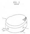
- Figure 3is an external perspective view illustrating an example of a cleaning robot in accordance with the present invention
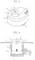
- Figure 4is a vertical-sectional view illustrating a sensor hiding unit for moving up and down a sensor assembly in accordance with the present invention
- Figure 5is an exploded-perspective view illustrating a position recognition apparatus for a cleaning robot in accordance with the present invention
- Figure 6is a vertical-sectional view illustrating a position information recognition apparatus for the cleaning robot in accordance with the present invention.
- the cleansing robot in accordance with the present inventionincludes a cleaner main body 1 including a fan, a motor, a suction pipe and a filter, etc.; plural driving wheels 2 rotatively installed at left and right bottom surfaces of the cleaner main body 1 and moving the cleaner main body 1 and a sensor assembly 10 rotatively installed at the cleaner main body 1 and observing the circumstances.
- a sensor assembly receiving portion 1Ais caved in so as to have a certain depth or is pierced in order to hide the sensor assembly 10.
- a sensor hiding unit 20is formed at a side of the sensor assembly receiving portion 1A in order to move the sensor assembly 10 up and down by being combined with a fixed plate 11 of the sensor assembly 10.
- the sensor hiding unitincludes a two-way rotational motor 21; a pinion 22 combined with a rotational axis of the two-way. rotational motor 21 so as to be rotated two-way; a rack 23 combined with the pinion 22 and linearly moved up and down according to the rotational direction of the pinion 22; and a sensor supporting plate 24 combined with the rack 23 as one body and combined with the fixed plate 11 of the sensor assembly 10.
- at least two guide protrusions 24Aare formed at the side surface of the sensor supporting plate 24, and it is preferable to form a long guide groove 1 B at the side wall of the sensor assembly receiving unit 1A in the length direction so as to be corresponded to the guide protrusions 24A.
- the sensor hiding unit 20can be constructed as a general pulley by using a motor and a rope.
- the sensor assembly 10includes a fixed plate 11 installed at the cleaner main body 1; a main motor 12 fixedly installed at the fixed plate 11 and generating a rotational force; a rotational cylinder 13 combined with a rotational axis 12a of the main motor 12 and rotating together with it; and plural (four in Figures 5 and 6) position information sensors 14 installed in the circumferential direction at a certain angle to the rotational cylinder 13 and sensing the surroundings.
- the fixed plate 11has a disc shape, and the main motor 12 is fastened-fixed to the central portion thereof by a screw.
- the fixed plate 11fixes the sensor supporting plate 24 as a part of the sensor hiding unit 20 by fastening a screw.
- the main motor 12is a two-way rotational motor performable forward and backward rotations, a rotational angle of the main motor 12 can be variously controlled according to the number of the position information sensors 14 and an appropriate sensing angle.
- an appropriate sensing angleis ⁇ 30°, when the number of the supersonic sensors is four, a rotational angle of the main motor 12 is controlled as ⁇ 45°, and it is preferable to perform an omnidirectional sensing.
- a guide plate supporting protrusion 12bis projected-formed at approximately three points centering around the rotational axis 12A so as to support the rotation guide plate 15.
- the rotational cylinder 13includes an inner cylinder 13A rotatively mounted on the top surface of the fixed plate 11, inserted into the outer circumference of the main motor 12 and having an electromotive protrusion 13a at the top inner circumference of the rotational cylinder 13 so as to be combined with the rotational axis 12a of the main motor 12; and an outer cylinder 13B combined with the top end of the inner cylinder 13A so as to be rotated together with and having the position information sensors 14 formed at the outer circumference at regular intervals.
- the inner cylinder 13Ahas a cylindrical shape having the open top and bottom' surfaces, and it is preferable to form flange portions 13b, 13c respectively at the lower outer circumference for the stable rotation and at the upper outer circumference for strong combination with the outer cylinder 13B.
- the electromotive protrusion 13ahas three legs, and a fixing hole 13d is formed at the center of the three legs so as to be combined with the rotational axis 12A of the electromotive motor 12.
- the outer cylinder 13Bhas the open bottom and the closed top surface as a cap sahpe, and a guide plate insertion hole 13e is formed at the center of the top surface so as to receive the rotation guide plate 15.
- the position information sensor 14 as a supersonic waves sensoris installed at the outer cylinder 13B of the rotational cylinder 13 at an angle of about 90° so as to have an appropriate sensitivity angle of about ⁇ 30°.
- the rotation guide plate 14has a diameter insertable into the top end of the inner cylinder 13A of the rotational cylinder 13 with a certain interval, a thickness of the rotation guide plate 15 is obtained by adding a length mounted on the.electromotive protrusion 13a of the inner cylinder 13A to a thickness of the outer cylinder 13B.
- a supporting hole 15ais formed at the central portion of the rotation guide plate 15 so as to receive the guide plate supporting protrusion 12b of the main motor 12.
- Non-described reference numeral 14ais a transmitter of the position information sensor 14, 14b is a receiver of the position information sensor 14, and 16 is a display.
- control unit of the cleanerjudges a charge level of the charging battery is lower at a certain level by checking it at any time, it rotates the driving wheels 2 in the forward or backward direction by adjusting a proceeding direction of the cleaner, and accordingly the cleaner main body 1 approaches a position at which a charger (not shown) is located.
- the position information sensor 14observes surroundings thoroughly, recognizes position information about surroundings and the charger and stores that in a microcomputer (not shown) in real time.
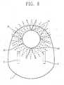
- Figure 8is a plan view schematically illustrating the position information recognition apparatus for the cleaning robot, when the main motor 12 is rotated, the rotational cylinder 13 performs the left-right rotation at an angle of ⁇ 45°. Simultaneously, the transmitter 14a of each position information sensor 14 installed at the outer cylinder 13B of the rotational cylinder 13 at an angle of 90° oscillates a certain sound wave, the receiver 14b receives the sound wave reflected from surrounded things, and each position information sensor 14 recognizes accurate position information.
- each position information sensor 14is installed so as to have an intermediate angle of about 90° with an appropriate sensitivity angle as ⁇ 30°, rotates left/right at an angle of about ⁇ 45°, and accordingly the it can observe surroundings of the cleaning robot thoroughly as 360°.
- the cleaner main bodycan perform only moving without performing additional rotational motion, and accordingly input loss can be reduced.
Landscapes
- Engineering & Computer Science (AREA)
- Radar, Positioning & Navigation (AREA)
- Remote Sensing (AREA)
- Physics & Mathematics (AREA)
- Aviation & Aerospace Engineering (AREA)
- General Physics & Mathematics (AREA)
- Automation & Control Theory (AREA)
- Acoustics & Sound (AREA)
- Control Of Position, Course, Altitude, Or Attitude Of Moving Bodies (AREA)
- Electric Vacuum Cleaner (AREA)
- Manipulator (AREA)
- Measurement Of Velocity Or Position Using Acoustic Or Ultrasonic Waves (AREA)
Abstract
Description
Claims (15)
- A position information recognition apparatus for a cleaning robot,comprising:a fixed plate installed at a cleaner main body;a main motor fixedly installed at the fixed plate in order to generate arotational force;a rotational cylinder combined with a rotational axis of the main motor soas to be rotated at a certain angle; andplural position information sensors installed at the rotational cylinder at acertain angle in order to sense surroundings.
- The apparatus of claim 1, wherein the fixed plate has a disc shape,and the lower end of the main motor is fastened-combined with the central portionof the fixed plate by a screw.
- The apparatus of claim 1, wherein the fixed plate includes asensor hiding means for ascending the position information sensor as a certainheight so as to be exposed outside of the cleaner main body in an operation stateand descending the position information sensor into the cleaner main body incharging or an operation stop state.
- The apparatus of claim 1, wherein the main motor is a two-wayrotational motor rotating forward or backward at a certain angle.
- The apparatus of claim 4, wherein the main motor has a rotationalangle as ±45°.
- The apparatus of claim 4, wherein the main motor has a guideplate supporting protrusion projected-formed at three points of the top surfacecentering around the rotational axis.
- The apparatus of claim 1, wherein the position information sensoris installed at the outer circumference of the rotational cylinder at an interval of 90°.
- The apparatus of claim 1, wherein the rotational cylinder includes:an inner cylinder rotatively mounted on the top portion of the fixed plate,inserted into the outer circumference of the main motor and having anelectromotive protrusion at the upper inner circumference of the rotational cylinderso as to be combined with the rotational axis of the main motor; andan outer cylinder fastened-combined with the upper end of the innercylinder so as to be rotated together with it and having the position informationsensors at the outer circumference of the rotational cylinder at regular intervals.
- The apparatus of claim 8, wherein the inner cylinder is cylindrical-shapedhaving the open top and bottom, a flange portion is formed at the lowerend outer circumference thereof to rotate the rotational cylinder stably, and aflange portion is formed at the upper end outer circumference thereof to becombined with the outer cylinder strongly.
- The apparatus of claim 8, wherein the outer cylinder has the openbottom and the closed top as a cap shape and includes an insertion hole formed atthe top central portion so as to receive the rotation guide plate.
- The apparatus of claim 1, wherein the rotational cylinder has aguide plate insertion hole at the top central portion in order to receive a rotationguide plate combined with the main motor as one body.
- The apparatus of claim 11, wherein an external display means isinstalled at the top surface of the guide plate in order to display information aboutan operational state of the cleaner or various circumstances.
- A main body of a cleaning robot, comprising:a sensor assembly rotatively installed at the top front surface of thecleaner main body in order to observe surroundings;a sensor assembly receiving portion concavely formed or pierced so as tohide the sensor assembly; anda sensor hiding unit formed at a side of the sensor assembly receivingportion in order to move the sensor assembly up and down.
- The main body of claim 13, wherein the sensor hiding unitincludes:a two-way rotational motor;a pinion combined with a rotational axis of the two-way rotational motorand being rotated two-way;a rack combined with the pinion and being linearly moved up and downaccording to the rotational direction of the pinion; anda sensor supporting plate formed as one body with the rack and combinedwith a fixed plate of the sensor assembly.
- The main body of claim 14, wherein the sensor supporting plateincludes at least two guide protrusions at a side surface and includes a long guidegroove at the side wall of the sensor assembly receiving portion so as to becorresponded to the guide protrusions.
Applications Claiming Priority (2)
| Application Number | Priority Date | Filing Date | Title |
|---|---|---|---|
| KR10-2003-0004573AKR100492588B1 (en) | 2003-01-23 | 2003-01-23 | Position information recognition apparatus for automatic running vacuum cleaner |
| KR2003004573 | 2003-01-23 |
Publications (3)
| Publication Number | Publication Date |
|---|---|
| EP1441271A2true EP1441271A2 (en) | 2004-07-28 |
| EP1441271A3 EP1441271A3 (en) | 2006-01-04 |
| EP1441271B1 EP1441271B1 (en) | 2011-03-16 |
Family
ID=32588994
Family Applications (1)
| Application Number | Title | Priority Date | Filing Date |
|---|---|---|---|
| EP03014676AExpired - LifetimeEP1441271B1 (en) | 2003-01-23 | 2003-06-27 | Position information recognition apparatus for cleaning robot |
Country Status (6)
| Country | Link |
|---|---|
| US (1) | US7103449B2 (en) |
| EP (1) | EP1441271B1 (en) |
| JP (1) | JP2004223703A (en) |
| KR (1) | KR100492588B1 (en) |
| CN (1) | CN100553904C (en) |
| DE (1) | DE60336376D1 (en) |
Cited By (28)
| Publication number | Priority date | Publication date | Assignee | Title |
|---|---|---|---|---|
| WO2007008148A1 (en)* | 2005-07-08 | 2007-01-18 | Ab Electrolux | Robotic cleaning device |
| RU2342898C1 (en)* | 2006-11-28 | 2009-01-10 | Самсунг Гуангджу Электроникс Ко., Лтд. | Robot-vacuum cleaner and control mode of robot-vacuum cleaner |
| US20100312390A1 (en)* | 2007-05-14 | 2010-12-09 | Robosoft | Domestic robot assistant having a rolling chassis |
| US9811089B2 (en) | 2013-12-19 | 2017-11-07 | Aktiebolaget Electrolux | Robotic cleaning device with perimeter recording function |
| US9939529B2 (en) | 2012-08-27 | 2018-04-10 | Aktiebolaget Electrolux | Robot positioning system |
| US9946263B2 (en) | 2013-12-19 | 2018-04-17 | Aktiebolaget Electrolux | Prioritizing cleaning areas |
| US10045675B2 (en) | 2013-12-19 | 2018-08-14 | Aktiebolaget Electrolux | Robotic vacuum cleaner with side brush moving in spiral pattern |
| US10149589B2 (en) | 2013-12-19 | 2018-12-11 | Aktiebolaget Electrolux | Sensing climb of obstacle of a robotic cleaning device |
| US10209080B2 (en) | 2013-12-19 | 2019-02-19 | Aktiebolaget Electrolux | Robotic cleaning device |
| US10219665B2 (en) | 2013-04-15 | 2019-03-05 | Aktiebolaget Electrolux | Robotic vacuum cleaner with protruding sidebrush |
| US10231591B2 (en) | 2013-12-20 | 2019-03-19 | Aktiebolaget Electrolux | Dust container |
| WO2019093831A1 (en) | 2017-11-10 | 2019-05-16 | Samsung Electronics Co., Ltd. | Robot cleaner and control method thereof |
| US10433697B2 (en) | 2013-12-19 | 2019-10-08 | Aktiebolaget Electrolux | Adaptive speed control of rotating side brush |
| US10448794B2 (en) | 2013-04-15 | 2019-10-22 | Aktiebolaget Electrolux | Robotic vacuum cleaner |
| US10499778B2 (en) | 2014-09-08 | 2019-12-10 | Aktiebolaget Electrolux | Robotic vacuum cleaner |
| US10518416B2 (en) | 2014-07-10 | 2019-12-31 | Aktiebolaget Electrolux | Method for detecting a measurement error in a robotic cleaning device |
| US10534367B2 (en) | 2014-12-16 | 2020-01-14 | Aktiebolaget Electrolux | Experience-based roadmap for a robotic cleaning device |
| US10617271B2 (en) | 2013-12-19 | 2020-04-14 | Aktiebolaget Electrolux | Robotic cleaning device and method for landmark recognition |
| US10678251B2 (en) | 2014-12-16 | 2020-06-09 | Aktiebolaget Electrolux | Cleaning method for a robotic cleaning device |
| US10729297B2 (en) | 2014-09-08 | 2020-08-04 | Aktiebolaget Electrolux | Robotic vacuum cleaner |
| US10877484B2 (en) | 2014-12-10 | 2020-12-29 | Aktiebolaget Electrolux | Using laser sensor for floor type detection |
| US10874274B2 (en) | 2015-09-03 | 2020-12-29 | Aktiebolaget Electrolux | System of robotic cleaning devices |
| US10874271B2 (en) | 2014-12-12 | 2020-12-29 | Aktiebolaget Electrolux | Side brush and robotic cleaner |
| US11099554B2 (en) | 2015-04-17 | 2021-08-24 | Aktiebolaget Electrolux | Robotic cleaning device and a method of controlling the robotic cleaning device |
| US11122953B2 (en) | 2016-05-11 | 2021-09-21 | Aktiebolaget Electrolux | Robotic cleaning device |
| US11169533B2 (en) | 2016-03-15 | 2021-11-09 | Aktiebolaget Electrolux | Robotic cleaning device and a method at the robotic cleaning device of performing cliff detection |
| US11474533B2 (en) | 2017-06-02 | 2022-10-18 | Aktiebolaget Electrolux | Method of detecting a difference in level of a surface in front of a robotic cleaning device |
| US11921517B2 (en) | 2017-09-26 | 2024-03-05 | Aktiebolaget Electrolux | Controlling movement of a robotic cleaning device |
Families Citing this family (58)
| Publication number | Priority date | Publication date | Assignee | Title |
|---|---|---|---|---|
| KR100608880B1 (en)* | 2005-02-28 | 2006-08-08 | 엘지전자 주식회사 | Motor Lock for Dishwasher |
| KR100700544B1 (en)* | 2005-08-09 | 2007-03-28 | 엘지전자 주식회사 | Robot cleaner with RF antenna |
| KR101223478B1 (en)* | 2005-08-10 | 2013-01-17 | 엘지전자 주식회사 | Apparatus sensing the engagement of a dust tank for a robot-cleaner |
| KR101233158B1 (en) | 2005-10-21 | 2013-02-15 | 엘지전자 주식회사 | Robot cleaner having Avatar Image Displaying Unit |
| USD550906S1 (en)* | 2005-10-31 | 2007-09-11 | H-Tech, Inc. | Pool cleaner housing |
| KR100791383B1 (en)* | 2006-07-07 | 2008-01-07 | 삼성전자주식회사 | Method and apparatus for estimating relative position between mobile robot and originating device |
| DE602007007026D1 (en)* | 2006-09-05 | 2010-07-22 | Lg Electronics Inc | cleaning robot |
| KR100818740B1 (en)* | 2006-10-13 | 2008-04-01 | 엘지전자 주식회사 | Robot cleaner and control method accordingly |
| US8489234B2 (en)* | 2007-07-18 | 2013-07-16 | Lg Electronics Inc. | Mobile robot and controlling method thereof |
| US8343339B2 (en) | 2008-09-16 | 2013-01-01 | Hayward Industries, Inc. | Apparatus for facilitating maintenance of a pool cleaning device |
| USD598168S1 (en) | 2008-09-16 | 2009-08-11 | Hayward Industries, Inc. | Pool cleaner |
| USD630808S1 (en) | 2009-07-01 | 2011-01-11 | Hayward Industries, Inc. | Pool cleaner |
| USD630809S1 (en) | 2009-07-01 | 2011-01-11 | Hayward Industries, Inc. | Pool cleaner |
| US9593502B2 (en) | 2009-10-19 | 2017-03-14 | Hayward Industries, Inc. | Swimming pool cleaner |
| CN102262407B (en)* | 2010-05-31 | 2016-08-03 | 恩斯迈电子(深圳)有限公司 | Guide and operating system |
| US8784652B2 (en) | 2010-09-24 | 2014-07-22 | Poolvergnuegen | Swimming pool cleaner with a rigid debris canister |
| CN102004251A (en)* | 2010-09-27 | 2011-04-06 | 北京航空航天大学 | Compass-based horizontal scanning ultrasonic distance measurement instrument |
| US8869337B2 (en) | 2010-11-02 | 2014-10-28 | Hayward Industries, Inc. | Pool cleaning device with adjustable buoyant element |
| CN102319698A (en)* | 2011-06-15 | 2012-01-18 | 李子京 | Automatic cleaning system and method of solar power station |
| CN103565344B (en)* | 2012-08-08 | 2017-04-19 | 科沃斯机器人股份有限公司 | Self-moving robot and walking method thereof |
| US9675226B2 (en) | 2012-10-26 | 2017-06-13 | Lg Electronics Inc. | Robot cleaner system and control method of the same |
| KR101450569B1 (en)* | 2013-03-05 | 2014-10-14 | 엘지전자 주식회사 | Robot cleaner |
| KR101490170B1 (en)* | 2013-03-05 | 2015-02-05 | 엘지전자 주식회사 | Robot cleaner |
| EP2967268A1 (en) | 2013-03-14 | 2016-01-20 | Hayward Industries, Inc. | Pool cleaner with articulated cleaning members |
| US9677294B2 (en) | 2013-03-15 | 2017-06-13 | Hayward Industries, Inc. | Pool cleaning device with wheel drive assemblies |
| KR101395888B1 (en)* | 2013-03-21 | 2014-05-27 | 엘지전자 주식회사 | Robot cleaner and operating method |
| KR102137156B1 (en)* | 2013-11-06 | 2020-07-24 | 엘지전자 주식회사 | Distance measuring scanner and operating method thereof |
| USD789624S1 (en) | 2014-11-07 | 2017-06-13 | Hayward Industries, Inc. | Pool cleaner |
| USD787761S1 (en) | 2014-11-07 | 2017-05-23 | Hayward Industries, Inc. | Pool cleaner |
| USD789003S1 (en) | 2014-11-07 | 2017-06-06 | Hayward Industries, Inc. | Pool cleaner |
| USD787760S1 (en) | 2014-11-07 | 2017-05-23 | Hayward Industries, Inc. | Pool cleaner |
| CN104858871B (en)* | 2015-05-15 | 2016-09-07 | 珠海市一微半导体有限公司 | Robot system and self-built map thereof and the method for navigation |
| KR101682811B1 (en)* | 2015-06-02 | 2016-12-12 | 동의대학교 산학협력단 | Method of controlling robot vaccume cleaner conducting abnormal infinite loop operation |
| KR20170077756A (en)* | 2015-12-28 | 2017-07-06 | 삼성전자주식회사 | Cleaning robot and controlling method thereof |
| CN105534413A (en)* | 2016-02-14 | 2016-05-04 | 海安欣凯富机械科技有限公司 | Control method of dust removal device |
| KR102601463B1 (en)* | 2016-10-28 | 2023-11-14 | 삼성전자주식회사 | Robot cleaner and driving method thereof |
| CN106580214A (en)* | 2016-11-25 | 2017-04-26 | 宁波欧琳厨具有限公司 | Cleaning machine |
| KR102631151B1 (en) | 2016-12-23 | 2024-01-31 | 엘지전자 주식회사 | Cleaning robot |
| CN117122247A (en)* | 2017-04-01 | 2023-11-28 | 北京石头世纪科技股份有限公司 | Intelligent cleaning equipment |
| US10214933B2 (en) | 2017-05-11 | 2019-02-26 | Hayward Industries, Inc. | Pool cleaner power supply |
| JPWO2018225172A1 (en)* | 2017-06-07 | 2019-11-07 | 学校法人千葉工業大学 | Self-propelled vacuum cleaner |
| CN109426268B (en)* | 2017-08-30 | 2024-04-16 | 苏州宝时得电动工具有限公司 | Self-moving equipment |
| CN108196459B (en)* | 2018-01-29 | 2021-07-13 | 山东泰鹏智能家居股份有限公司 | Multimedia device of smart home |
| TWI660275B (en)* | 2018-06-27 | 2019-05-21 | 廣達電腦股份有限公司 | Methods and systems of distributing task areas for cleaning devices, and cleaning devices |
| US11194335B2 (en)* | 2018-07-10 | 2021-12-07 | Neato Robotics, Inc. | Performance-based cleaning robot charging method and apparatus |
| JP2020010982A (en)* | 2018-07-20 | 2020-01-23 | パナソニックIpマネジメント株式会社 | Self-propelled vacuum cleaner |
| KR102117868B1 (en)* | 2019-02-28 | 2020-06-04 | 한국생산기술연구원 | Lidar driving part with height control and robot cleaner with using the same |
| WO2020184738A1 (en)* | 2019-03-08 | 2020-09-17 | 엘지전자 주식회사 | Robot |
| WO2020184739A1 (en)* | 2019-03-08 | 2020-09-17 | 엘지전자 주식회사 | Robot |
| KR102791416B1 (en)* | 2019-06-04 | 2025-04-08 | 삼성전자주식회사 | A robot cleaner |
| KR102290612B1 (en)* | 2019-11-21 | 2021-08-20 | 한국생산기술연구원 | A lidar rotating device of robot cleaner and method for correcting rotation angle |
| JP7430540B2 (en)* | 2020-02-03 | 2024-02-13 | 株式会社マキタ | Detection device and robot dust collector |
| CN116172445A (en)* | 2020-02-27 | 2023-05-30 | 北京石头创新科技有限公司 | Carpet identification method for cleaning robot |
| JP2021007051A (en)* | 2020-10-12 | 2021-01-21 | 学校法人千葉工業大学 | Self-propelled vacuum cleaner |
| JP2021010761A (en)* | 2020-10-12 | 2021-02-04 | 学校法人千葉工業大学 | Self-propelled vacuum cleaner |
| KR20220071032A (en)* | 2020-11-23 | 2022-05-31 | 에브리봇 주식회사 | Lidar Apparatus And Robot Cleaner Using The Same |
| CN112976017B (en)* | 2021-05-10 | 2021-07-30 | 北京创泽智慧机器人科技有限公司 | Enterprise safety production hidden danger investigation equipment based on intelligent inspection robot |
| KR20230122878A (en)* | 2022-02-15 | 2023-08-22 | 삼성전자주식회사 | Washing machine |
Family Cites Families (25)
| Publication number | Priority date | Publication date | Assignee | Title |
|---|---|---|---|---|
| DE3741259A1 (en) | 1987-12-05 | 1989-06-15 | Hipp Johann F | Method and device for the autonomous steering of a vehicle |
| JPH03138708A (en)* | 1989-10-25 | 1991-06-13 | Honda Motor Co Ltd | Travel course setting device for self-propelled vehicles |
| KR920007557Y1 (en)* | 1990-11-28 | 1992-10-16 | 주식회사 금성사 | Supersonic-radar device of vacuum cleaner |
| US5400244A (en) | 1991-06-25 | 1995-03-21 | Kabushiki Kaisha Toshiba | Running control system for mobile robot provided with multiple sensor information integration system |
| JPH05143155A (en) | 1991-11-19 | 1993-06-11 | Nec Home Electron Ltd | Cleaning robot |
| IL100633A (en)* | 1992-01-12 | 1999-04-11 | Israel State | Large area movement robot |
| US5440216A (en)* | 1993-06-08 | 1995-08-08 | Samsung Electronics Co., Ltd. | Robot cleaner |
| DE4408982C1 (en)* | 1994-03-16 | 1995-05-18 | Deutsche Forsch Luft Raumfahrt | Autonomous navigation system for mobile robot or manipulator |
| JP2778458B2 (en)* | 1994-03-30 | 1998-07-23 | 日本電気株式会社 | Traveling robot |
| KR970000582B1 (en)* | 1994-03-31 | 1997-01-14 | 삼성전자 주식회사 | Driving control method of robot cleaner |
| KR0161042B1 (en)* | 1994-06-07 | 1999-01-15 | 김광호 | Moving control device and method of robot |
| JP3296105B2 (en)* | 1994-08-26 | 2002-06-24 | ミノルタ株式会社 | Autonomous mobile robot |
| AU1775401A (en)* | 1999-11-18 | 2001-05-30 | Procter & Gamble Company, The | Home cleaning robot |
| US6374155B1 (en)* | 1999-11-24 | 2002-04-16 | Personal Robotics, Inc. | Autonomous multi-platform robot system |
| US7155308B2 (en)* | 2000-01-24 | 2006-12-26 | Irobot Corporation | Robot obstacle detection system |
| US6594844B2 (en)* | 2000-01-24 | 2003-07-22 | Irobot Corporation | Robot obstacle detection system |
| US6496754B2 (en)* | 2000-11-17 | 2002-12-17 | Samsung Kwangju Electronics Co., Ltd. | Mobile robot and course adjusting method thereof |
| US6883201B2 (en)* | 2002-01-03 | 2005-04-26 | Irobot Corporation | Autonomous floor-cleaning robot |
| US7571511B2 (en)* | 2002-01-03 | 2009-08-11 | Irobot Corporation | Autonomous floor-cleaning robot |
| SE518683C2 (en)* | 2001-03-15 | 2002-11-05 | Electrolux Ab | Method and apparatus for determining the position of an autonomous apparatus |
| KR100437372B1 (en)* | 2001-04-18 | 2004-06-25 | 삼성광주전자 주식회사 | Robot cleaning System using by mobile communication network |
| US6580246B2 (en)* | 2001-08-13 | 2003-06-17 | Steven Jacobs | Robot touch shield |
| JP3812463B2 (en)* | 2002-03-08 | 2006-08-23 | 株式会社日立製作所 | Direction detecting device and self-propelled cleaner equipped with the same |
| US7113847B2 (en)* | 2002-05-07 | 2006-09-26 | Royal Appliance Mfg. Co. | Robotic vacuum with removable portable vacuum and semi-automated environment mapping |
| ES2674568T3 (en)* | 2002-09-13 | 2018-07-02 | Irobot Corporation | Navigation control system for a robotic device |
- 2003
- 2003-01-23KRKR10-2003-0004573Apatent/KR100492588B1/ennot_activeExpired - Fee Related
- 2003-06-26USUS10/606,213patent/US7103449B2/ennot_activeExpired - Lifetime
- 2003-06-27EPEP03014676Apatent/EP1441271B1/ennot_activeExpired - Lifetime
- 2003-06-27DEDE60336376Tpatent/DE60336376D1/ennot_activeExpired - Lifetime
- 2003-07-25JPJP2003201905Apatent/JP2004223703A/enactivePending
- 2003-07-28CNCNB031436242Apatent/CN100553904C/ennot_activeExpired - Fee Related
Non-Patent Citations (1)
| Title |
|---|
| None |
Cited By (32)
| Publication number | Priority date | Publication date | Assignee | Title |
|---|---|---|---|---|
| US8032978B2 (en) | 2005-07-08 | 2011-10-11 | Ab Electrolux | Robotic cleaning device |
| WO2007008148A1 (en)* | 2005-07-08 | 2007-01-18 | Ab Electrolux | Robotic cleaning device |
| RU2342898C1 (en)* | 2006-11-28 | 2009-01-10 | Самсунг Гуангджу Электроникс Ко., Лтд. | Robot-vacuum cleaner and control mode of robot-vacuum cleaner |
| US20100312390A1 (en)* | 2007-05-14 | 2010-12-09 | Robosoft | Domestic robot assistant having a rolling chassis |
| US9939529B2 (en) | 2012-08-27 | 2018-04-10 | Aktiebolaget Electrolux | Robot positioning system |
| US10219665B2 (en) | 2013-04-15 | 2019-03-05 | Aktiebolaget Electrolux | Robotic vacuum cleaner with protruding sidebrush |
| US10448794B2 (en) | 2013-04-15 | 2019-10-22 | Aktiebolaget Electrolux | Robotic vacuum cleaner |
| US9946263B2 (en) | 2013-12-19 | 2018-04-17 | Aktiebolaget Electrolux | Prioritizing cleaning areas |
| US10149589B2 (en) | 2013-12-19 | 2018-12-11 | Aktiebolaget Electrolux | Sensing climb of obstacle of a robotic cleaning device |
| US10209080B2 (en) | 2013-12-19 | 2019-02-19 | Aktiebolaget Electrolux | Robotic cleaning device |
| US10045675B2 (en) | 2013-12-19 | 2018-08-14 | Aktiebolaget Electrolux | Robotic vacuum cleaner with side brush moving in spiral pattern |
| US10617271B2 (en) | 2013-12-19 | 2020-04-14 | Aktiebolaget Electrolux | Robotic cleaning device and method for landmark recognition |
| US10433697B2 (en) | 2013-12-19 | 2019-10-08 | Aktiebolaget Electrolux | Adaptive speed control of rotating side brush |
| US9811089B2 (en) | 2013-12-19 | 2017-11-07 | Aktiebolaget Electrolux | Robotic cleaning device with perimeter recording function |
| US10231591B2 (en) | 2013-12-20 | 2019-03-19 | Aktiebolaget Electrolux | Dust container |
| US10518416B2 (en) | 2014-07-10 | 2019-12-31 | Aktiebolaget Electrolux | Method for detecting a measurement error in a robotic cleaning device |
| US10729297B2 (en) | 2014-09-08 | 2020-08-04 | Aktiebolaget Electrolux | Robotic vacuum cleaner |
| US10499778B2 (en) | 2014-09-08 | 2019-12-10 | Aktiebolaget Electrolux | Robotic vacuum cleaner |
| US10877484B2 (en) | 2014-12-10 | 2020-12-29 | Aktiebolaget Electrolux | Using laser sensor for floor type detection |
| US10874271B2 (en) | 2014-12-12 | 2020-12-29 | Aktiebolaget Electrolux | Side brush and robotic cleaner |
| US10678251B2 (en) | 2014-12-16 | 2020-06-09 | Aktiebolaget Electrolux | Cleaning method for a robotic cleaning device |
| US10534367B2 (en) | 2014-12-16 | 2020-01-14 | Aktiebolaget Electrolux | Experience-based roadmap for a robotic cleaning device |
| US11099554B2 (en) | 2015-04-17 | 2021-08-24 | Aktiebolaget Electrolux | Robotic cleaning device and a method of controlling the robotic cleaning device |
| US10874274B2 (en) | 2015-09-03 | 2020-12-29 | Aktiebolaget Electrolux | System of robotic cleaning devices |
| US11712142B2 (en) | 2015-09-03 | 2023-08-01 | Aktiebolaget Electrolux | System of robotic cleaning devices |
| US11169533B2 (en) | 2016-03-15 | 2021-11-09 | Aktiebolaget Electrolux | Robotic cleaning device and a method at the robotic cleaning device of performing cliff detection |
| US11122953B2 (en) | 2016-05-11 | 2021-09-21 | Aktiebolaget Electrolux | Robotic cleaning device |
| US11474533B2 (en) | 2017-06-02 | 2022-10-18 | Aktiebolaget Electrolux | Method of detecting a difference in level of a surface in front of a robotic cleaning device |
| US11921517B2 (en) | 2017-09-26 | 2024-03-05 | Aktiebolaget Electrolux | Controlling movement of a robotic cleaning device |
| EP3675702A4 (en)* | 2017-11-10 | 2020-08-19 | Samsung Electronics Co., Ltd. | CLEANING ROBOTS AND CONTROL PROCEDURES FOR IT |
| WO2019093831A1 (en) | 2017-11-10 | 2019-05-16 | Samsung Electronics Co., Ltd. | Robot cleaner and control method thereof |
| US11064858B2 (en) | 2017-11-10 | 2021-07-20 | Samsung Electronics Co., Ltd. | Robot cleaner and control method thereof |
Also Published As
| Publication number | Publication date |
|---|---|
| US7103449B2 (en) | 2006-09-05 |
| CN1517188A (en) | 2004-08-04 |
| KR20040067463A (en) | 2004-07-30 |
| EP1441271B1 (en) | 2011-03-16 |
| JP2004223703A (en) | 2004-08-12 |
| US20040199301A1 (en) | 2004-10-07 |
| EP1441271A3 (en) | 2006-01-04 |
| DE60336376D1 (en) | 2011-04-28 |
| CN100553904C (en) | 2009-10-28 |
| KR100492588B1 (en) | 2005-06-03 |
Similar Documents
| Publication | Publication Date | Title |
|---|---|---|
| EP1441271A2 (en) | Position information recognition apparatus for cleaning robot | |
| EP3599962B1 (en) | Cleaner and method of controlling the same | |
| US11892849B2 (en) | Moving robot and control method thereof | |
| US11537135B2 (en) | Moving robot and controlling method for the moving robot | |
| US5646494A (en) | Charge induction apparatus of robot cleaner and method thereof | |
| US9785148B2 (en) | Moving robot and controlling method thereof | |
| EP3000369B1 (en) | Robot cleaner and robot cleaner system including the same | |
| EP3513644A1 (en) | Mowing robot | |
| EP3258825B1 (en) | Robot cleaner, remote control system including the same, and control method thereof | |
| US8800101B2 (en) | Robot cleaner and self testing method of the same | |
| AU2010232114B2 (en) | Mobile robot with single camera and method for recognizing 3D surroundings of the same | |
| EP1430826A2 (en) | Automatic charging device and method of automatically travelling cleaner | |
| US20060261772A1 (en) | Position-recognizing system for self-moving robot | |
| EP2749194B1 (en) | Automatic cleaner | |
| RU2478335C1 (en) | Vacuum cleaner and vacuum cleaner control method | |
| AU2022201782B2 (en) | Moving robot | |
| KR20210084392A (en) | Moving robot and Controlling method for the same | |
| US20230180988A1 (en) | Robot cleaner and method of controlling robot cleaner | |
| KR100437157B1 (en) | Robot cleaner and system and method of rejoining the same with external charging apparatus | |
| KR102320560B1 (en) | A moving robot and controlling method for the moving robot | |
| KR100812370B1 (en) | Robot Cleaner Combination Air Conditioner | |
| US20230255431A1 (en) | Robot cleaner and method of controlling the same | |
| CN213665072U (en) | Robot cleaner | |
| US20220408992A1 (en) | Robot vacuum cleaner | |
| CN218927808U (en) | Palm sound positioning and moving device |
Legal Events
| Date | Code | Title | Description |
|---|---|---|---|
| PUAI | Public reference made under article 153(3) epc to a published international application that has entered the european phase | Free format text:ORIGINAL CODE: 0009012 | |
| 17P | Request for examination filed | Effective date:20031230 | |
| AK | Designated contracting states | Kind code of ref document:A2 Designated state(s):AT BE BG CH CY CZ DE DK EE ES FI FR GB GR HU IE IT LI LU MC NL PT RO SE SI SK TR | |
| AX | Request for extension of the european patent | Extension state:AL LT LV MK | |
| PUAL | Search report despatched | Free format text:ORIGINAL CODE: 0009013 | |
| AK | Designated contracting states | Kind code of ref document:A3 Designated state(s):AT BE BG CH CY CZ DE DK EE ES FI FR GB GR HU IE IT LI LU MC NL PT RO SE SI SK TR | |
| AX | Request for extension of the european patent | Extension state:AL LT LV MK | |
| RIC1 | Information provided on ipc code assigned before grant | Ipc:G05D 1/02 20060101AFI20040503BHEP Ipc:A47L 11/40 20060101ALI20051115BHEP | |
| AKX | Designation fees paid | Designated state(s):DE FR GB | |
| 17Q | First examination report despatched | Effective date:20070116 | |
| GRAP | Despatch of communication of intention to grant a patent | Free format text:ORIGINAL CODE: EPIDOSNIGR1 | |
| GRAS | Grant fee paid | Free format text:ORIGINAL CODE: EPIDOSNIGR3 | |
| GRAA | (expected) grant | Free format text:ORIGINAL CODE: 0009210 | |
| AK | Designated contracting states | Kind code of ref document:B1 Designated state(s):DE FR GB | |
| REG | Reference to a national code | Ref country code:GB Ref legal event code:FG4D | |
| REF | Corresponds to: | Ref document number:60336376 Country of ref document:DE Date of ref document:20110428 Kind code of ref document:P | |
| REG | Reference to a national code | Ref country code:DE Ref legal event code:R096 Ref document number:60336376 Country of ref document:DE Effective date:20110428 | |
| PLBE | No opposition filed within time limit | Free format text:ORIGINAL CODE: 0009261 | |
| STAA | Information on the status of an ep patent application or granted ep patent | Free format text:STATUS: NO OPPOSITION FILED WITHIN TIME LIMIT | |
| 26N | No opposition filed | Effective date:20111219 | |
| REG | Reference to a national code | Ref country code:DE Ref legal event code:R097 Ref document number:60336376 Country of ref document:DE Effective date:20111219 | |
| PGFP | Annual fee paid to national office [announced via postgrant information from national office to epo] | Ref country code:FR Payment date:20140513 Year of fee payment:12 | |
| REG | Reference to a national code | Ref country code:FR Ref legal event code:ST Effective date:20160229 | |
| PG25 | Lapsed in a contracting state [announced via postgrant information from national office to epo] | Ref country code:FR Free format text:LAPSE BECAUSE OF NON-PAYMENT OF DUE FEES Effective date:20150630 | |
| PGFP | Annual fee paid to national office [announced via postgrant information from national office to epo] | Ref country code:GB Payment date:20190503 Year of fee payment:17 | |
| PGFP | Annual fee paid to national office [announced via postgrant information from national office to epo] | Ref country code:DE Payment date:20200506 Year of fee payment:18 | |
| GBPC | Gb: european patent ceased through non-payment of renewal fee | Effective date:20200627 | |
| PG25 | Lapsed in a contracting state [announced via postgrant information from national office to epo] | Ref country code:GB Free format text:LAPSE BECAUSE OF NON-PAYMENT OF DUE FEES Effective date:20200627 | |
| REG | Reference to a national code | Ref country code:DE Ref legal event code:R119 Ref document number:60336376 Country of ref document:DE | |
| PG25 | Lapsed in a contracting state [announced via postgrant information from national office to epo] | Ref country code:DE Free format text:LAPSE BECAUSE OF NON-PAYMENT OF DUE FEES Effective date:20220101 |