EP1438985A1 - Implantable medical device e.g. a pacemaker with means for determining the presence and the type of the associated probe - Google Patents
Implantable medical device e.g. a pacemaker with means for determining the presence and the type of the associated probeDownload PDFInfo
- Publication number
- EP1438985A1 EP1438985A1EP04290130AEP04290130AEP1438985A1EP 1438985 A1EP1438985 A1EP 1438985A1EP 04290130 AEP04290130 AEP 04290130AEP 04290130 AEP04290130 AEP 04290130AEP 1438985 A1EP1438985 A1EP 1438985A1
- Authority
- EP
- European Patent Office
- Prior art keywords
- probe
- case
- bipolar
- width
- stimulation
- Prior art date
- Legal status (The legal status is an assumption and is not a legal conclusion. Google has not performed a legal analysis and makes no representation as to the accuracy of the status listed.)
- Granted
Links
- 239000000523sampleSubstances0.000titleclaimsabstractdescription131
- 238000001514detection methodMethods0.000claimsabstractdescription18
- 239000002184metalSubstances0.000claimsabstractdescription7
- 230000000638stimulationEffects0.000claimsdescription89
- 238000002513implantationMethods0.000claimsdescription27
- 230000004913activationEffects0.000claimsdescription15
- 230000000694effectsEffects0.000claimsdescription5
- 230000009471actionEffects0.000claimsdescription3
- 230000033764rhythmic processEffects0.000claimsdescription2
- 239000003990capacitorSubstances0.000description9
- 230000006870functionEffects0.000description9
- 230000008878couplingEffects0.000description6
- 238000010168coupling processMethods0.000description6
- 238000005859coupling reactionMethods0.000description6
- 238000000034methodMethods0.000description5
- 230000000747cardiac effectEffects0.000description3
- 239000004020conductorSubstances0.000description3
- 238000010586diagramMethods0.000description3
- 238000003780insertionMethods0.000description3
- 230000037431insertionEffects0.000description3
- 230000028161membrane depolarizationEffects0.000description3
- 230000004048modificationEffects0.000description3
- 238000012986modificationMethods0.000description3
- 238000012360testing methodMethods0.000description3
- 208000033986Device capturing issueDiseases0.000description2
- 230000003213activating effectEffects0.000description2
- 229940082150encoreDrugs0.000description2
- 230000007246mechanismEffects0.000description2
- 238000012544monitoring processMethods0.000description2
- 230000001681protective effectEffects0.000description2
- 240000008042Zea maysSpecies0.000description1
- 230000001746atrial effectEffects0.000description1
- 238000012550auditMethods0.000description1
- 230000008901benefitEffects0.000description1
- 230000008859changeEffects0.000description1
- 238000004891communicationMethods0.000description1
- 230000009849deactivationEffects0.000description1
- 230000007423decreaseEffects0.000description1
- 208000037265diseases, disorders, signs and symptomsDiseases0.000description1
- 208000035475disorderDiseases0.000description1
- 210000002837heart atriumAnatomy0.000description1
- 238000002847impedance measurementMethods0.000description1
- 230000005764inhibitory processEffects0.000description1
- 238000009434installationMethods0.000description1
- 238000004519manufacturing processMethods0.000description1
- 238000005259measurementMethods0.000description1
- 230000002107myocardial effectEffects0.000description1
- 230000007170pathologyEffects0.000description1
- 238000012545processingMethods0.000description1
- 238000005086pumpingMethods0.000description1
- 238000004904shorteningMethods0.000description1
- 230000002861ventricularEffects0.000description1
- 238000012795verificationMethods0.000description1
Images


Classifications
- A—HUMAN NECESSITIES
- A61—MEDICAL OR VETERINARY SCIENCE; HYGIENE
- A61N—ELECTROTHERAPY; MAGNETOTHERAPY; RADIATION THERAPY; ULTRASOUND THERAPY
- A61N1/00—Electrotherapy; Circuits therefor
- A61N1/18—Applying electric currents by contact electrodes
- A61N1/32—Applying electric currents by contact electrodes alternating or intermittent currents
- A61N1/36—Applying electric currents by contact electrodes alternating or intermittent currents for stimulation
- A61N1/362—Heart stimulators
- A61N1/37—Monitoring; Protecting
- A—HUMAN NECESSITIES
- A61—MEDICAL OR VETERINARY SCIENCE; HYGIENE
- A61B—DIAGNOSIS; SURGERY; IDENTIFICATION
- A61B90/00—Instruments, implements or accessories specially adapted for surgery or diagnosis and not covered by any of the groups A61B1/00 - A61B50/00, e.g. for luxation treatment or for protecting wound edges
- A61B90/90—Identification means for patients or instruments, e.g. tags
- A61B90/98—Identification means for patients or instruments, e.g. tags using electromagnetic means, e.g. transponders
Definitions
- the inventionrelates to "active implantable medical devices" such as defined by Directive 90/385 / EEC of June 20, 1990 of the Community Council European, in particular cardiac pacemakers, defibrillators, cardioverters and / or “multisite” devices allowing to deliver low energy electrical pulses to the heart for the treatment of heart rhythm disorders.
- active implantable medical devicessuch as defined by Directive 90/385 / EEC of June 20, 1990 of the Community Council European, in particular cardiac pacemakers, defibrillators, cardioverters and / or “multisite” devices allowing to deliver low energy electrical pulses to the heart for the treatment of heart rhythm disorders.
- These devicesinclude a generator containing in the same housing the various electronic circuits and their supply battery. At time implantation, this generator is electrically and mechanically connected to a probe provided with intracardiac stimulation electrodes allowing to detect the potentials of myocardial depolarization and to deliver to the latter the stimulation pulses produced by the generator.
- the devicein particular its microprocessor, is placed in a standby mode with very low consumption, and a mechanism is provided to detect from inside the device the connection of a probe, in order to detect the implantation and wake up the generator circuit to make it fully functional and initialize a number of parameters, store initial data, etc.
- This activation functioncan be carried out in various ways.
- US-A-5 350 407provides an activation pin to be removed by the surgeon in the pacemaker at the time of implantation, to authorize the establishment of a communication link with a programmer external which will send a deactivation order to the stimulator.
- US-A-5,522,856 and US-A-5,370,666detect the insertion of a probe by an impedance measurement made between the terminals of the connector head of the device: in the absence of a probe, this impedance is extremely high, but upon insertion of a probe the value decreases below a certain threshold whose crossing is detected to exit the standby mode stimulator and place it in a mode where it becomes totally functional.
- One of the aims of the inventionis to propose a circuit which can fully automatic, detect the connection of a probe in order to to switch the device from a standby mode with very low consumption towards a mode where all the functionalities will be activated (with, correlatively, higher consumption level).
- the inventionachieves this goal without any intervention of the surgeon, so without manipulation or risk of forgetting (as in the case of a system requiring the insertion of an activation pin), without direct and permanent measurement of the impedance between terminals, and without the need for an external programmer.
- the inventionalso aims to provide a device which can, fully autonomous, not only detect the connection of a probe, but also and above all determine the type of probe used - monopolar or bipolar - and switch and configure accordingly the various circuits and algorithms of the device.
- This functionmanaged completely automatically by the device, avoids any risk of error resulting from a lack of conformity between the type of probe used and the operating mode of the device (this is avoided, for example, any risk of bipolar stimulation applied in error to a monopolar probe).
- Another object of the inventionis to propose a device incorporating a security function to detect the particular configuration in which the pacemaker, after having been fitted with a bipolar probe, is not yet introduced into the implantation site (the incision or "pocket” in which the surgeon plans to place the pulse generator), and is not connected to a potential reference electrode or plate.
- the stimulatoris generally programmed by default in monopolar stimulation (factory setting). In this case, it is absolutely essential that the generator does not deliver monopolar stimulation pulses on the bipolar probe, because these pulses would be dangerous due to absence of ground return, the generator housing being electrically in the air during this stage; security should be maintained until final and complete functional activation of the device.
- the device of the inventionmakes it possible to automatically detect this configuration, to inhibit the delivery of bipolar stimulation, inhibition which will be maintained as long as the situation persists and which will be automatically lifted as soon as the link to the reference potential will be restored by inserting the generator housing in the pocket or by connecting it to a potential reference plate, thus making it possible to close the ground circuit electrically.
- Activation of the pacemaker functionswill therefore be fully automatic in the case of a bipolar probe.
- the implanting surgeonwill not not to use a reference plate or to force a stimulation mode bipolar prior to implanting the generator in the pocket ; he will just have to insert the bipolar probe, and security will be automatically insured for the time necessary to complete the implantation.
- Yet another object of the inventionis to propose a device allowing also ensure continuous, cycle-to-cycle integrity monitoring of the probe during operation, in particular to detect rupture of the conductor of the proximal electrode of a bipolar probe, so to immediately switch the operating mode of the device in monopolar mode, since in this case the probe remains functional, but in the latter mode only.
- the inventionprovides a device of the aforementioned type, comprising a metal case containing a generator, capable of producing pulses stimulation in monopolar or bipolar mode, connected to a connector head provided with at least two terminals capable of being connected to electrodes of a detection and stimulation probe connected to the connector, this probe can be a monopolar probe or a bipolar probe.
- the generatorincludes means for detecting the presence a probe connected to the connector.
- the detection meanscomprise : means for producing monopolar stimulation pulses or bipolar, selectively with or without disconnection of the link at the reference potential; means to collect at least one signal impulse produced by the variation of potential induced on one and / or the other of the terminals and / or on the metal case by the application of said stimulation pulses; discriminatory means, suitable for analysis a shape characteristic of said at least one impulse signal and to issue an indicator representative of the presence or absence of a probe; and control means, for modifying at least one parameter of operation of the device selectively according to the indicator issued by discriminatory means.
- the shape parameteris in particular the width of said at least one signal impulse, this width being compared to one or more threshold (s).
- the means for producing pulses of stimulationapply a stimulation pulse with disconnection of the link to the reference potential, and the discriminating means compare to a given threshold the width of the pulse signal collected on the terminal of the proximal electrode and on the housing.
- the means for producing pulses of stimulationapply a bipolar stimulation pulse between the terminal of the proximal electrode and the terminal of the distal electrode, without disconnecting the link to the reference potential, and the means discriminators compare the width of the pulse signal collected on the housing at a high threshold and a low threshold.
- control meansfrom an initial state of the device where it, before implantation, operates temporarily in a reduced functionality mode, upon delivery of a representative indicator the presence of a probe, put the device in a mode fully functional.
- the control meansupon delivery of an indicator representative of the presence of a probe, can also perform at least one action among: activation of the device's analog detection circuits; activation physiological or activity sensors; type programming stimulation, monopolar or bipolar, depending on the indicator delivered ; initialization of the device operating algorithms; discount at zero and activation of the diagnostic counters; memorialization from the date of implementation.
- Security meansmay also be provided which, when the device operates in bipolar stimulation on a bipolar probe and in case issuing an indicator not representative of the presence of a bipolar probe, put the device in a safety mode with monopolar stimulation. Likewise, when the device receives from an external programmer, a setting instruction in bipolar stimulation, these safety means do not allow activation of the bipolar stimulation mode only if the discriminating means deliver bipolar stimulation only if the discriminating means deliver an indicator representative of the presence of a bipolar probe.
- FIG. 1is a schematic representation of the device according to the invention, with a generator fitted with a bipolar probe.
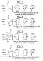
- Figures 2 to 5show, for four different situations, a share (left) the equivalent electrical circuit seen from the device terminals and on the other hand (on the right) the forms of the impulses likely to be collected on the various terminals of the device when applying a pulse stimulation, in the case where the link to the reference potential has been intentionally disconnected.
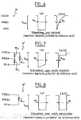
- Figures 6 to 8are equivalent to Figures 2 to 5, in the case where a connection to the reference potential is established.
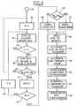
- Figure 9is a flowchart showing the different steps of the algorithm detecting the presence of a probe and the type of probe, as well as actions taken accordingly.
- Figure 10is a flowchart showing how it is possible detect, during operation, a loss of probe integrity bipolar.
- Figure 11is a flow diagram of the steps showing the different steps of the algorithm allowing, on the one hand, to increase the lifespan of the device by standby before implantation and, on the other hand, detection of the configuration where the case, after having been provided with a bipolar probe, has not yet been inserted into the pocket by the surgeon.
- FIG. 1shows, schematically, a stimulator device cardiac (or a device including cardiac stimulation functions), essentially comprising a generator 10 and a stimulation probe 12.
- the metal housing of the generatoris internally connected to a terminal 22, generally designated "CASE”, and used as a reference potential compared to the RING and TIP electrodes for collecting potentials depolarization and / or the application of stimulation pulses.
- CASEa terminal 22 compared to the RING and TIP electrodes for collecting potentials depolarization and / or the application of stimulation pulses.
- the generatorincludes a charge pumping circuit 24 ensuring the charging of a high capacity capacitor C STO . Once this capacitor has been charged, the stimulation pulse can be delivered by closing the switch 26 controlled by a STIM command delivered by the microcontroller, which has the effect of transferring the energy accumulated in the capacitor C STO to the terminal TIP 16 , via a C OUT decoupling capacitor.
- a bipolar probe(case illustrated in Figure 1), it is the RING 20 terminal which constitutes the electrical reference, and which is therefore connected to the internal ground of the generator by closing a switch S 1 controlled by a BIP signal produced by the microcontroller.
- S 1When S 1 is open, a resistor R 1 is inserted between the ground and the electrode 20; moreover, a capacitor C 1 between terminals 16 and 20 provides protection against various electromagnetic interference.
- this discriminationcan be achieved by a pulse width analysis and comparison of this width to different thresholds.
- a first possibilityconsists in delivering a stimulation pulse with the two connections to the reference potential disconnected (that is to say S 1 and S 2 open), and to observe the forms of wave collected on the RING and CASE electrodes.
- This possibilityalthough it requires the analysis of the signal on two electrodes and the delivery of a stimulation pulse which is not captured by the heart, has the advantage of authorizing the detection of a partially implanted device , with a bipolar probe connected to the generator but the latter being located outside the pocket.
- This facultycan be used in particular, as will be explained below, to "wake up” the generator by bringing it out of a low consumption mode and by executing a certain number of initialization steps, as is will set out below, with particular reference to the flow diagram of FIG. 11.
- FIGS. 6 to 8consists in delivering a stimulation pulse with the two connections to the established reference potential (that is to say S 1 and S 2 closed).
- the stimulation pulse appliedis a bipolar pulse, that is to say applied between the terminals TIP and RING.
- the inventioncould be implemented in a comparable manner by applying a monopolar stimulation pulse (therefore between the CASE and TIP electrodes) and by observing the shape of the pulse collected on the RING electrode. This variant, although less advantageous, should nevertheless be understood as falling within the scope of the present invention.
- Detection of the presence of a probethe type of probe and the implantation effective is operated by measuring by means of a detector circuit pulse width 28 the width of the pulses collected on the terminals CASE 22 and RING 20, as we will now explain.
- the external configuration 30(FIG. 2) of the CASE, RING and TIP electrodes seen by the device corresponds to a very high impedance, theoretically infinite, between any two of these three bounds.
- a stimulation pulse applied by the device with the two connections to the reference potential disconnected(that is to say S 1 and S 2 open) has the shape illustrated in FIG. 2, namely a rectangular slot shape. of height V STIM and of width W P.
- the CASE and RING terminalsare coupled to the TIP terminal via the respective protection capacitors C 2 and C 1 .
- the circuit 28will therefore see on these terminals CASE and RING pulses as illustrated in FIG. 2, with a steep edge then a return to the initial level according to a time constant defined by R 1 and C 1 or R 2 and C 2 , the duration W O at half height of the pulses thus collected being of the order of 200 ⁇ s.
- FIG 3illustrates the case where the stimulator was equipped with a bipolar probe, but where the generator housing has not yet been implanted in the pocket, nor connected to an electrode or potential reference plate.
- the impedance network 30, seen from inside the stimulatoronly has an impedance RL 2 between the two electrodes RING and TIP, since the electrode CASE is electrically in the air.
- the stimulation pulse applied to the TIP terminalalways has the form of a slot and the pulse collected on the CASE terminal has the same appearance as before, due to the only internal coupling by the protective capacitor C 2 , with a abrupt side then a gradual return to the initial level.
- the pulse collected on the RING terminalhas the form of a slot similar to the stimulation pulse delivered on the TIP terminal, due to the external coupling by the RL 2 impedance.
- FIG 4illustrates the case where the stimulator was equipped with a bipolar probe, with the generator housing implanted in the pocket or else connected to a reference electrode.
- the impedance network 30 corresponding to this probeseen from inside the stimulator, includes impedances RL 1 , RL 2 and RL 3 between the three electrodes TIP, CASE and RING taken two by two.
- the pulses collected on the CASE and RING terminalsthen both have the form of a slot similar to the stimulation pulse delivered on the TIP terminal, due to the external coupling with the latter by the impedance RL 1 , RL 2 and RL 3 .
- the last case, illustrated in FIG. 5,is that where the stimulator is equipped with a monopolar probe, with the generator case implanted in the pocket or else connected to a reference electrode (it will be noted that with a monopolar probe, if the housing has not yet been implanted, nor connected to a reference electrode, the situation is identical to that of FIG. 2; the stimulator being by default in monopolar stimulation (factory setting), the situation does not present any risk and no particular security measure is to be taken before the complete functional activation of the device).
- the impedance configuration 30is that illustrated in FIG. 5, namely a single impedance RL 1 between CASE and TIP, with a very high impedance, theoretically infinite, between RING and CASE or RING and TIP.
- the pulse collected on the CASE terminalhas the form of a slot similar to the stimulation pulse delivered on the TIP terminal, due to the external coupling by the RL 1 impedance.
- the pulse collected on the RING terminalhas an abrupt edge then a gradual return to the initial level, due to the internal coupling by the protective capacitor C 1 .
- the simple analysis of the pulses on the terminals CASE 22 and RING 20 by the detector circuit 28makes it possible to discriminate between a generator not implanted (FIG. 2) and a generator partially implanted (FIGS. 3 to 5).
- the width of the signal detected both on the CASE and RING terminalsis W O.
- the width on CASE and / or RINGbecomes W P.
- This discriminationmakes it possible to detect immediately, that is to say in the interval of a heartbeat, the connection, even partial, a bipolar or monopolar probe, whether or not the generator is placed in the pocket.
- This detectionis used in particular to "wake up" immediately the generator and take it out of a low consumption mode in which it found and switch it to a mode where it will be fully functional, with in particular a security stimulation ensuring the capture of the impulse stimulation for the duration of the implantation procedure.
- Figure 6shows the shape of the pulse collected on the CASE terminal for a bipolar pulse applied between the TIP and RING terminals, when the generator not installed: the pulse observed on the CASE terminal presents a very steep front followed by a relatively exponential decay slow, defined by the time constant of the internal components
- the duration W O of the mid-level pulsebeing approximately 200 ⁇ s.
- FIG. 7shows the shape of the pulse collected on the CASE terminal when the bipolar pulse is applied with the generator correctly installed and provided with a bipolar probe: in such a case, the generator circuit sees three impedances RL 1 , RL 2 and RL 3 between the three respective electrodes TIP, CASE and RING of the probe.
- the shape of the pulse observed on the CASE terminal when a stimulation pulse is applied between the TIP and RING terminalsdrops to V STIM and rises rapidly, with a time constant RL 1 / (RL 2 + RL 3 ) * C 1 .
- the maximum duration of the pulseis less than 20 ⁇ s, a value defining a low threshold W MIN .
- Figure 8shows the shape of the pulse collected on the CASE terminal when the bipolar pulse is applied between the TIP and CASE terminals with the generator correctly installed and provided with a monopolar probe: in such a case, the impedance between TIP and CASE is only that of tissues, while that between TIP and RING, or between RING and CASE, is very high, theoretically infinite. The shape of the signal observed on the CASE terminal is therefore practically the same as that of the pulse detected on the TIP terminal, due to the low impedance RL 1 coupling the CASE and TIP terminals.
- Circuit 28is a circuit whose detection thresholds have been programmed so suitable for unambiguously discriminating between the three scenarios that we just exposed.
- Figure 9is a flowchart showing the various steps of the algorithm allowing to detect the implantation of the device and to configure it Consequently.
- the generatordetects the width W of the pulse picked up on the CASE terminal of the generator operating in bipolar stimulation mode (step 38). If the width of this pulse is greater than a predetermined threshold value W MIN and less than the value W P of the stimulation pulse (step 40), this means that the device is not yet implanted, and the latter returns then to the security stimulation mode of step 34.
- step 42the counter N is decremented by one unit and, if it is not zero (step 44), the counting of the period T is reset (step 46) and the device returns to step 34 of the stimulation mode of security.
- step 40has detected three times in succession on the terminal CASE a pulse of width less than W MIN or equal to W P , that is to say has detected the presence of '' a probe, therefore the fact that the device has been definitively implanted (as a precaution, the period T is chosen so that 3.T corresponds to a duration greater than the average duration of an implantation, i.e. 3.T> 20 mins approximately).
- the stimulatordetermines, depending on the pulse width on the CASE terminal, whether it is a bipolar or monopolar probe (steps 48, 50 and 52). if the pulse width is less than W MIN , the implanted probe is a bipolar probe, while if this width is greater than or equal to W P , it is a monopolar probe.
- the safety stimulationis then stopped (step 54) and the stimulation in programmed mode is activated (step 56).
- an algorithmis also activated which, according to the invention, continuous verification of the integrity of the probe (step 58, which will be described in more detail with reference to Figure 10).
- step 60the physiological algorithms are initialized (step 60), the counters are reset and activated (step 62) and, if the device is provided with a real-time clock, the implementation date is entered in memory (step 64).
- FIG. 10illustrates the manner in which the method of the invention allows continuous monitoring of the integrity of a bipolar probe after implantation thereof.
- This methodallows in particular to detect a break in the conductor of the proximal electrode 18, which would result in a loss of capture likely to cause major risks for the patient.
- This breakhas the effect of modifying the impedance of the equivalent circuit 30 so that the pulse received on the CASE electrode will have the shape illustrated, with a width W P.
- bipolar stimulationis programmed (step 66) and the width W of the pulse collected on the CASE terminal is less than the W MIN threshold (step 68), this means that the probe is intact (see below) .
- the bipolar probebehaves like a monopolar probe, which is revealed by a shortening of the pulse collected on the terminal CASE, to a width substantially equal to W P.
- the devicethen switches to monopolar stimulation mode (step 72) for safety. This condition is temporary, until confirmed by three successive matching tests during a given time interval T (steps 72 to 82). If the fault is thus confirmed, then the pacemaker permanently switches to monopolar stimulation (step 84).
- this methodcan also be used to avoid that, by error, a practitioner only reprograms bipolar stimulation on a device which had been implanted with a monopolar probe, a situation which would have the same consequences as breaking the electrode conductor proximal of a bipolar probe.
- Figure 11illustrates how the method of the invention can be used to improve the lifespan of the device, and to take into counts the special case where the stimulator was fitted with a bipolar probe, but where the generator housing has not yet been installed in the pocket, nor connected to a potential reference electrode or plate.
- analog circuitsdetection amplifiers, sensor bias circuits and analog signal processing circuits
- the microcontroller functionsare minimized, with a simple stimulation at a slow rate, for example 70 cpm on the atrium and the ventricle, sufficient stimulation to allow detection of a probe (steps 86 to 90).
- the deviceswitches its operating mode by leaving the low consumption standby mode (step 92), by activating the programmed stimulation mode , monopolar or bipolar (step 93), by triggering the activation of detection amplifiers and other analog circuits (step 94), by activating physiological or activity sensors (step 96) and by restoring the programmed parameters (step 98) .
Landscapes
- Health & Medical Sciences (AREA)
- Life Sciences & Earth Sciences (AREA)
- Public Health (AREA)
- Nuclear Medicine, Radiotherapy & Molecular Imaging (AREA)
- Veterinary Medicine (AREA)
- General Health & Medical Sciences (AREA)
- Surgery (AREA)
- Animal Behavior & Ethology (AREA)
- Engineering & Computer Science (AREA)
- Biomedical Technology (AREA)
- Heart & Thoracic Surgery (AREA)
- Medical Informatics (AREA)
- Molecular Biology (AREA)
- Electromagnetism (AREA)
- Pathology (AREA)
- Physics & Mathematics (AREA)
- Oral & Maxillofacial Surgery (AREA)
- Cardiology (AREA)
- Radiology & Medical Imaging (AREA)
- Electrotherapy Devices (AREA)
Abstract
Translated fromFrenchDescription
Translated fromFrenchL'invention concerne les "dispositifs médicaux implantables actifs" tels quedéfinis par la Directive 90/385/CEE du 20 juin 1990 du Conseil des communautéseuropéennes, notamment les dispositifs stimulateurs cardiaques,défibrillateurs, cardioverteurs et/ou dispositifs "multisite" permettantde délivrer au coeur des impulsions électriques de faible énergie pour letraitement des troubles du rythme cardiaque.The invention relates to "active implantable medical devices" such asdefined by
Ces dispositifs comportent un générateur contenant dans un même boítierles divers circuits électroniques et leur pile d'alimentation. Au moment del'implantation, ce générateur est relié électriquement et mécaniquement àune sonde pourvue d'électrodes de stimulation intracardiaque permettantde détecter les potentiels de dépolarisation du myocarde et de délivrer àce dernier les impulsions de stimulation produites par le générateur.These devices include a generator containing in the same housingthe various electronic circuits and their supply battery. At timeimplantation, this generator is electrically and mechanically connected toa probe provided with intracardiac stimulation electrodes allowingto detect the potentials of myocardial depolarization and to deliver tothe latter the stimulation pulses produced by the generator.
Il est généralement possible de relier à un même générateur deux typesde sonde différents, monopolaire ou bipolaire, au choix du chirurgien selonle type de pathologie à traiter. Dans le cas d'une sonde monopolaire(ou "unipolaire"), la détection et la stimulation sont opérées entre l'électrodeunique et le boítier métallique du générateur, tandis que dans unesonde bipolaire, détection et stimulation peuvent effectuées soit en modedifférentiel entre deux électrodes de la sonde, soit en mode commun entrele boítier du générateur et l'une ou l'autre des électrodes.It is generally possible to connect two types to the same generatordifferent probe, monopolar or bipolar, depending on the surgeon's choicethe type of pathology to be treated. In the case of a monopolar probe(or "unipolar"), detection and stimulation are performed between the electrodesingle and the metal housing of the generator, while in abipolar probe, detection and stimulation can be performed either in modedifferential between two probe electrodes, either in common mode betweenthe generator housing and one or the other of the electrodes.
Bien entendu, de nombreux paramètres internes du générateur doiventêtre choisis en fonction du type de sonde utilisée, monopolaire ou bipolaire: commutation des bornes devant être utilisées, recueil des signaux dedépolarisation, ajustement des paramètres de stimulation, modificationdes algorithmes de pilotage du microprocesseur, etc. On comprendra quetoute erreur dans la sélection du type de fonctionnement (monopolaire oubipolaire) peut entraíner des conséquences extrêmement graves : parexemple, si le dispositif est programmé pour une stimulation bipolairemais qu'il est équipé d'une sonde monopolaire, cette erreur va provoquerune perte de capture et l'application d'une stimulation inappropriée, avecun risque majeur pour le patient.Of course, many internal parameters of the generator mustbe chosen according to the type of probe used, monopolar or bipolar: switching of the terminals to be used, collection of thedepolarization, adjustment of stimulation parameters, modificationmicroprocessor control algorithms, etc. We will understand thatany error in the selection of the type of operation (monopolar orbipolar) can have extremely serious consequences:example, if the device is programmed for bipolar stimulationbut that it is equipped with a monopolar probe, this error will causeloss of capture and the application of inappropriate stimulation, witha major risk for the patient.
Par ailleurs, après la fabrication du générateur, il peut s'écouler un laps detemps important entre l'expédition de ce générateur et son implantationdans le corps du patient. Ce délai peut atteindre un an, voire dix-huit mois.Pendant cette période, parfois longue, précédant l'implantation, il est essentiel que l'appareil, dont la pile a été connectée juste avant l'expédition,présente une consommation la plus réduite possible, de manière que ladurée de stockage n'ait pas d'incidence notable sur la durée de vie del'appareil, c'est-à-dire la durée pendant laquelle ce dernier sera fonctionnelaprès implantation.In addition, after manufacturing the generator, there may be a lapse ofsignificant time between the shipment of this generator and its installationin the patient's body. This period can reach a year or even eighteen months.During this period, sometimes long, preceding implantation, it is essentialthat the device, whose battery was connected just before shipping,has the lowest possible consumption, so that theshelf life has no significant impact on the shelf life ofthe device, i.e. the period during which it will be operationalafter implantation.
Pour ce faire, le dispositif, notamment son microprocesseur, est placédans un mode de veille à très faible consommation, et il est prévu un mécanismepour détecter de l'intérieur du dispositif la connexion d'une sonde,afin de détecter ainsi l'implantation et réveiller le circuit du générateurpour le rendre pleinement fonctionnel et initialiser un certain nombre deparamètres, mémoriser des données de départ, etc.To do this, the device, in particular its microprocessor, is placedin a standby mode with very low consumption, and a mechanism is providedto detect from inside the device the connection of a probe,in order to detect the implantation and wake up the generator circuitto make it fully functional and initialize a number ofparameters, store initial data, etc.
Cette fonction d'activation peut être réalisée de diverses manières.This activation function can be carried out in various ways.
Ainsi, le US-A-5 350 407 prévoit une goupille d'activation devant être retiréepar le chirurgien dans le stimulateur au moment de l'implantation, pourautoriser l'établissement d'une liaison de communication avec un programmateurexterne qui enverra un ordre de désactivation au stimulateur.Thus, US-A-5 350 407 provides an activation pin to be removedby the surgeon in the pacemaker at the time of implantation, toauthorize the establishment of a communication link with a programmerexternal which will send a deactivation order to the stimulator.
Les US-A-5 522 856 et US-A-5 370 666 détectent l'insertion d'une sondepar une mesure d'impédance effectuée entre les bornes de la tête de connecteurdu dispositif : en l'absence de sonde, cette impédance est extrêmementélevée, mais dès l'insertion d'une sonde la valeur décroít au dessousd'un certain seuil dont le franchissement est détecté pour sortir lestimulateur du mode de veille et le placer dans un mode où il devient totalementfonctionnel.US-A-5,522,856 and US-A-5,370,666 detect the insertion of a probeby an impedance measurement made between the terminals of the connector headof the device: in the absence of a probe, this impedance is extremelyhigh, but upon insertion of a probe the value decreases belowa certain threshold whose crossing is detected to exit thestandby mode stimulator and place it in a mode where it becomes totallyfunctional.
L'un des buts de l'invention est de proposer un circuit qui puisse, de façonentièrement automatique, détecter le branchement d'une sonde afin defaire basculer le dispositif d'un mode de veille à très faible consommationvers un mode où toutes les fonctionnalités seront activées (avec, corrélativement,un niveau de consommation supérieur).One of the aims of the invention is to propose a circuit which canfully automatic, detect the connection of a probe in order toto switch the device from a standby mode with very low consumptiontowards a mode where all the functionalities will be activated (with, correlatively,higher consumption level).
Comme on le verra, l'invention permet d'atteindre ce but sans aucune interventiondu chirurgien, donc sans manipulation ni risque d'oubli (commedans le cas d'un système nécessitant l'insertion d'une goupille d'activation),sans effectuer de mesure directe et permanente de l'impédance entreles bornes, et sans recours à un programmateur externe.As will be seen, the invention achieves this goal without any interventionof the surgeon, so without manipulation or risk of forgetting (asin the case of a system requiring the insertion of an activation pin),without direct and permanent measurement of the impedance betweenterminals, and without the need for an external programmer.
L'invention a également pour but de proposer un dispositif qui puisse, demanière entièrement autonome, non seulement détecter le branchement d'une sonde, mais également et surtout déterminer le type de sonde utilisée- monopolaire ou bipolaire - et commuter et paramétrer en conséquenceles divers circuits et algorithmes du dispositif. Cette fonction, géréede façon entièrement automatique par le dispositif, permet d'évitertout risque d'erreur résultant d'un défaut de conformité entre le type desonde utilisée et le mode de fonctionnement du dispositif (on évite ainsi,par exemple, tout risque de stimulation bipolaire appliquée par erreur àune sonde monopolaire).The invention also aims to provide a device which can,fully autonomous, not only detect the connectionof a probe, but also and above all determine the type of probe used- monopolar or bipolar - and switch and configure accordinglythe various circuits and algorithms of the device. This function, managedcompletely automatically by the device, avoidsany risk of error resulting from a lack of conformity between the type ofprobe used and the operating mode of the device (this is avoided,for example, any risk of bipolar stimulation applied in error toa monopolar probe).
Un autre but de l'invention est de proposer un dispositif incorporant unefonction de sécurité permettant de détecter la configuration particulièredans laquelle le stimulateur, après avoir été équipé d'une sonde bipolaire,n'est pas encore introduit dans le site d'implantation (l'incision ou "poche"dans laquelle le chirurgien prévoit de placer le générateur d'impulsions), etn'est pas relié à une électrode ou plaque de référence de potentiel. Or lestimulateur est généralement programmé par défaut en stimulation monopolaire(réglage d'usine). Dans ce cas, il est absolument indispensableque le générateur ne délivre pas d'impulsions de stimulation monopolairesur la sonde bipolaire, car ces impulsions seraient dangereuses du fait del'absence de retour de masse, le boítier du générateur étant électriquementen l'air pendant cette étape ; la sécurité doit être maintenue jusqu'àl'activation fonctionnelle définitive et complète du dispositif.Another object of the invention is to propose a device incorporating asecurity function to detect the particular configurationin which the pacemaker, after having been fitted with a bipolar probe,is not yet introduced into the implantation site (the incision or "pocket"in which the surgeon plans to place the pulse generator), andis not connected to a potential reference electrode or plate. Now thestimulator is generally programmed by default in monopolar stimulation(factory setting). In this case, it is absolutely essentialthat the generator does not deliver monopolar stimulation pulseson the bipolar probe, because these pulses would be dangerous due toabsence of ground return, the generator housing being electricallyin the air during this stage; security should be maintained untilfinal and complete functional activation of the device.
On verra que le dispositif de l'invention permet de détecter automatiquementcette configuration, pour inhiber la délivrance d'une stimulation bipolaire,inhibition qui sera maintenue tant que la situation persistera et quisera automatiquement levée dès que la liaison au potentiel de référencesera rétablie par l'insertion du boítier du générateur dans la poche ou bienpar un branchement de celui-ci à une plaque de référence de potentiel,permettant ainsi de refermer électriquement le circuit de masse.We will see that the device of the invention makes it possible to automatically detectthis configuration, to inhibit the delivery of bipolar stimulation,inhibition which will be maintained as long as the situation persists and whichwill be automatically lifted as soon as the link to the reference potentialwill be restored by inserting the generator housing in the pocket orby connecting it to a potential reference plate,thus making it possible to close the ground circuit electrically.
L'activation des fonctionnalités du stimulateur sera ainsi totalement automatiquedans le cas d'une sonde bipolaire. Le chirurgien implanteur n'aurapas à utiliser de plaque de référence où à forcer un mode de stimulationbipolaire préalablement à l'implantation du générateur dans la poche; il lui suffira d'insérer la sonde bipolaire, et la sécurité sera automatiquementassurée pendant la durée nécessaire à l'achèvement de l'implantation.Activation of the pacemaker functions will therefore be fully automaticin the case of a bipolar probe. The implanting surgeon will notnot to use a reference plate or to force a stimulation modebipolar prior to implanting the generator in the pocket; he will just have to insert the bipolar probe, and security will be automaticallyinsured for the time necessary to complete the implantation.
Un autre but encore de l'invention est de proposer un dispositif permettantd'assurer en outre une surveillance continue, cycle à cycle, de l'intégritéde la sonde en cours de fonctionnement, notamment pour détecter la rupturedu conducteur de l'électrode proximale d'une sonde bipolaire, de manièreà basculer immédiatement le mode de fonctionnement du dispositifen mode monopolaire, puisque dans ce cas la sonde reste fonctionnelle,mais dans ce dernier mode seulement.Yet another object of the invention is to propose a device allowingalso ensure continuous, cycle-to-cycle integrity monitoringof the probe during operation, in particular to detect ruptureof the conductor of the proximal electrode of a bipolar probe, soto immediately switch the operating mode of the devicein monopolar mode, since in this case the probe remains functional,but in the latter mode only.
À cet effet, l'invention propose un dispositif du type précité, comprenantun boítier métallique contenant un générateur, apte à produire des impulsionsde stimulation en mode monopolaire ou en mode bipolaire, relié àune tête de connecteur pourvue d'au moins deux bornes aptes à être reliéesà des électrodes d'une sonde de détection et de stimulation reliée auconnecteur, cette sonde pouvant être une sonde monopolaire ou unesonde bipolaire. Le générateur inclut des moyens de détection de la présenced'une sonde reliée au connecteur.To this end, the invention provides a device of the aforementioned type, comprisinga metal case containing a generator, capable of producing pulsesstimulation in monopolar or bipolar mode, connected toa connector head provided with at least two terminals capable of being connectedto electrodes of a detection and stimulation probe connected to theconnector, this probe can be a monopolar probe or abipolar probe. The generator includes means for detecting the presencea probe connected to the connector.
De façon caractéristique de l'invention, les moyens de détection comprennent: des moyens pour produire des impulsions de stimulation monopolairesou bipolaires, sélectivement avec ou sans déconnexion de la liaisonau potentiel de référence ; des moyens pour recueillir au moins un signalimpulsionnel produit par la variation de potentiel induite sur l'une et/oul'autre des bornes et/ou sur le boítier métallique par l'application desditesimpulsions de stimulation ; des moyens discriminateurs, propres à analyserune caractéristique de forme dudit au moins un signal impulsionnel età délivrer un indicateur représentatif de la présence ou de l'absence d'unesonde ; et des moyens de commande, pour modifier au moins un paramètrede fonctionnement du dispositif sélectivement en fonction de l'indicateurdélivré par les moyens discriminateurs.Characteristically of the invention, the detection means comprise: means for producing monopolar stimulation pulsesor bipolar, selectively with or without disconnection of the linkat the reference potential; means to collect at least one signalimpulse produced by the variation of potential induced on one and / orthe other of the terminals and / or on the metal case by the application of saidstimulation pulses; discriminatory means, suitable for analysisa shape characteristic of said at least one impulse signal andto issue an indicator representative of the presence or absence of aprobe; and control means, for modifying at least one parameterof operation of the device selectively according to the indicatorissued by discriminatory means.
Le paramètre de forme est notamment la largeur dudit au moins un signalimpulsionnel, cette largeur étant comparée à un ou des seuil(s).The shape parameter is in particular the width of said at least one signalimpulse, this width being compared to one or more threshold (s).
Selon un premier aspect de l'invention, les moyens pour produire des impulsionsde stimulation appliquent une impulsion de stimulation avec déconnexionde la liaison au potentiel de référence, et les moyens discriminateurscomparent à un seuil donné la largeur du signal impulsionnel recueillisur la borne de l'électrode proximale et sur le boítier.According to a first aspect of the invention, the means for producing pulsesof stimulation apply a stimulation pulse with disconnectionof the link to the reference potential, and the discriminating meanscompare to a given threshold the width of the pulse signal collectedon the terminal of the proximal electrode and on the housing.
Les moyens discriminateurs peuvent alors délivrer un indicateur représentatif:
- de l'absence d'une sonde ou de la non-implantation du boítier aprèsconnexion d'une sonde lorsque la largeur du signal impulsionnel sur leboítier est inférieure au seuil ;
- de la présence d'une sonde monopolaire implanté lorsque la largeurdu signal impulsionnel recueilli sur le boítier est supérieure ou égaleaudit seuil et la largeur du signal impulsionnel recueilli sur la borne del'électrode proximale est inférieure au seuil ; ou
- de la présence d'une sonde bipolaire implantée lorsque la largeur dusignal impulsionnel recueilli sur le boítier et sur la borne proximale estsupérieure ou égale au seuil.
- the absence of a probe or the non-implantation of the housing after connection of a probe when the width of the pulse signal on the housing is less than the threshold;
- the presence of a monopolar probe implanted when the width of the pulse signal collected on the housing is greater than or equal to said threshold and the width of the pulse signal collected on the terminal of the proximal electrode is less than the threshold; or
- the presence of a bipolar probe implanted when the width of the pulse signal collected on the housing and on the proximal terminal is greater than or equal to the threshold.
Si, dans ce cas, les moyens pour produire des impulsions de stimulationappliquent une impulsion de stimulation bipolaire sans déconnexion de laliaison au potentiel de référence, les moyens discriminateurs peuvent, encomparant la largeur du signal impulsionnel recueilli sur le boítier à unseuil bas et à un seuil haut et délivrer un indicateur représentatif :
- de la présence d'une sonde bipolaire lorsque la largeur du signal impulsionnelsur le boítier est inférieure au seuil bas ;
- de l'absence d'une sonde lorsque la largeur du signal impulsionnel surle boítier est comprise entre le seuil bas et le seuil haut ; ou
- de la présence d'une sonde monopolaire lorsque la largeur du signalimpulsionnel sur le boítier est égale au seuil haut.
- the presence of a bipolar probe when the width of the pulse signal on the housing is less than the low threshold;
- the absence of a probe when the width of the pulse signal on the housing is between the low threshold and the high threshold; or
- the presence of a monopolar probe when the width of the pulse signal on the housing is equal to the high threshold.
Si, dans ce même cas, les moyens pour produire des impulsions de stimulationappliquent une impulsion de stimulation monopolaire sans déconnexionde la liaison au potentiel de référence, les moyens discriminateurspeuvent délivrer un indicateur représentatif :
- de l'absence d'une sonde lorsque la largeur du signal impulsionnel surla borne de l'électrode proximale est comprise entre le seuil bas et leseuil haut ;
- de la présence d'une sonde bipolaire lorsque la largeur du signal impulsionnelsur la borne de l'électrode proximale est inférieure au seuilbas ; ou
- de la présence d'une sonde monopolaire lorsque la largeur du signalimpulsionnel sur la borne de l'électrode proximale est égale au seuilhaut.
- the absence of a probe when the width of the pulse signal on the terminal of the proximal electrode is between the low threshold and the high threshold;
- the presence of a bipolar probe when the width of the pulse signal on the terminal of the proximal electrode is less than the low threshold; or
- the presence of a monopolar probe when the width of the pulse signal on the terminal of the proximal electrode is equal to the high threshold.
Selon un second aspect de l'invention, les moyens pour produire des impulsionsde stimulation appliquent une impulsion de stimulation bipolaireentre la borne de l'électrode proximale et la borne de l'électrode distale,sans déconnexion de la liaison au potentiel de référence, et les moyensdiscriminateurs comparent la largeur du signal impulsionnel recueilli sur leboítier à un seuil haut et à un seuil bas.According to a second aspect of the invention, the means for producing pulsesof stimulation apply a bipolar stimulation pulsebetween the terminal of the proximal electrode and the terminal of the distal electrode,without disconnecting the link to the reference potential, and the meansdiscriminators compare the width of the pulse signal collected on thehousing at a high threshold and a low threshold.
Les moyens discriminateurs peuvent alors délivrer un indicateur représentatif:
- de l'absence d'une sonde ou de la non-implantation du boítier aprèsconnexion d'une sonde lorsque la largeur du signal impulsionnel sur leboítier est comprise entre les deux seuils ;
- de la présence d'une sonde bipolaire lorsque la largeur du signal impulsionnelsur le boítier est inférieure au seuil bas ; ou
- de la présence d'une sonde monopolaire lorsque la largeur du signalimpulsionnel sur le boítier est égale au seuil haut.
- the absence of a probe or the non-implantation of the housing after connection of a probe when the width of the pulse signal on the housing is between the two thresholds;
- the presence of a bipolar probe when the width of the pulse signal on the housing is less than the low threshold; or
- the presence of a monopolar probe when the width of the pulse signal on the housing is equal to the high threshold.
Avantageusement, les moyens de commande, à partir d'un état initial dudispositif où celui-ci, avant implantation, opère temporairement dans unmode à fonctionnalités réduites, sur délivrance d'un indicateur représentatifde la présence d'une sonde, font passer le dispositif dans un modepleinement fonctionnel.Advantageously, the control means, from an initial state of thedevice where it, before implantation, operates temporarily in areduced functionality mode, upon delivery of a representative indicatorthe presence of a probe, put the device in a modefully functional.
Les moyens de commande, sur délivrance d'un indicateur représentatif dela présence d'une sonde, peuvent en outre exécuter au moins une actionparmi : activation des circuits analogiques de détection du dispositif ; activationdes capteurs physiologiques ou d'activité ; programmation du typede stimulation, monopolaire ou bipolaire, en fonction de l'indicateur délivré; initialisation des algorithmes de fonctionnement du dispositif ; remiseà zéro et activation des compteurs de diagnostic ; inscription en mémoirede la date d'implantation.The control means, upon delivery of an indicator representative ofthe presence of a probe, can also perform at least one actionamong: activation of the device's analog detection circuits; activationphysiological or activity sensors; type programmingstimulation, monopolar or bipolar, depending on the indicator delivered; initialization of the device operating algorithms; discountat zero and activation of the diagnostic counters; memorializationfrom the date of implementation.
Il peut également être prévu des moyens de sécurité qui, lorsque ledispositif opère en stimulation bipolaire sur une sonde bipolaire et en casde délivrance d'un indicateur non représentatif de la présence d'unesonde bipolaire, font passer le dispositif dans un mode de sécurité avecstimulation monopolaire. De la même façon, lorsque le dispositif reçoitd'un programmateur externe une instruction de paramétrage en mode destimulation bipolaire, ces moyens de sécurité n'autorisent l'activation dumode de stimulation bipolaire que si les moyens discriminateurs délivrent stimulation bipolaire que si les moyens discriminateurs délivrent un indicateurreprésentatif de la présence d'une sonde bipolaire.Security means may also be provided which, when thedevice operates in bipolar stimulation on a bipolar probe and in caseissuing an indicator not representative of the presence of abipolar probe, put the device in a safety mode withmonopolar stimulation. Likewise, when the device receivesfrom an external programmer, a setting instruction inbipolar stimulation, these safety means do not allow activation of thebipolar stimulation mode only if the discriminating means deliverbipolar stimulation only if the discriminating means deliver an indicatorrepresentative of the presence of a bipolar probe.
On va maintenant décrire un exemple de mise en oeuvre de l'invention, enréférence aux dessins annexés.We will now describe an example of implementation of the invention, inreference to the accompanying drawings.
La figure 1 est une représentation schématique du dispositif selon l'invention,avec un générateur équipé d'une sonde bipolaire.FIG. 1 is a schematic representation of the device according to the invention,with a generator fitted with a bipolar probe.
Les figures 2 à 5 représentent, pour quatre situations différentes, d'unepart (à gauche) le circuit électrique équivalent vu des bornes du dispositifet d'autre part (à droite) les formes des impulsions susceptibles d'être recueilliessur les diverses bornes du dispositif à l'application d'une impulsionde stimulation, dans le cas où la liaison au potentiel de référence aété volontairement déconnectée.Figures 2 to 5 show, for four different situations, ashare (left) the equivalent electrical circuit seen from the device terminalsand on the other hand (on the right) the forms of the impulses likely to be collectedon the various terminals of the device when applying a pulsestimulation, in the case where the link to the reference potential hasbeen intentionally disconnected.
Les figures 6 à 8 sont homologues des figures 2 à 5, dans le cas où uneliaison au potentiel de référence est établie.Figures 6 to 8 are equivalent to Figures 2 to 5, in the case where aconnection to the reference potential is established.
La figure 9 est un organigramme montrant les différentes étapes de l'algorithmede détection de la présence d'une sonde et du type de sonde, ainsique des actions prises en conséquence.Figure 9 is a flowchart showing the different steps of the algorithmdetecting the presence of a probe and the type of probe, as wellas actions taken accordingly.
La figure 10 est un organigramme montrant la manière dont il est possiblede détecter, en cours de fonctionnement, une perte d'intégrité d'une sondebipolaire.Figure 10 is a flowchart showing how it is possibledetect, during operation, a loss of probe integritybipolar.
La figure 11 est un organigramme des étapes montrant les différentesétapes de l'algorithme permettant, d'une part, d'augmenter la durée de viedu dispositif par mise en veille avant l'implantation et, d'autre part, la détectionde la configuration où le boítier, après avoir été pourvu d'unesonde bipolaire, n'a pas encore été introduit dans la poche par le chirurgien.Figure 11 is a flow diagram of the steps showing the differentsteps of the algorithm allowing, on the one hand, to increase the lifespanof the device by standby before implantation and, on the other hand, detectionof the configuration where the case, after having been provided with abipolar probe, has not yet been inserted into the pocket by the surgeon.
La figure 1 représente, de façon schématique, un dispositif stimulateurcardiaque (ou un dispositif incluant des fonctions de stimulation cardiaque),comprenant essentiellement un générateur 10 et une sonde de stimulation 12.Figure 1 shows, schematically, a stimulator devicecardiac (or a device including cardiac stimulation functions),essentially comprising a
Sur la figure 1, la sonde illustrée est une sonde bipolaire, comprenantdonc deux électrodes :
- une électrode distale 14, en bout de sonde, reliée à une borne 16 dugénérateur, borne généralement désignée "TIP" ;
- une électrode proximale 18, de forme annulaire, reliée à une autreborne 20 du générateur, généralement désignée "RING".
- a
distal electrode 14, at the end of the probe, connected to aterminal 16 of the generator, terminal generally designated "TIP"; - a
proximal electrode 18, of annular shape, connected to anotherterminal 20 of the generator, generally designated "RING".
Par ailleurs, le boítier métallique du générateur est relié en interne à uneborne 22, généralement désignée "CASE", et utilisée comme référence depotentiel par rapport aux électrodes RING et TIP pour le recueil des potentielsde dépolarisation et/ou l'application d'impulsions de stimulation.In addition, the metal housing of the generator is internally connected to aterminal 22, generally designated "CASE", and used as a referencepotential compared to the RING and TIP electrodes for collecting potentialsdepolarization and / or the application of stimulation pulses.
Le générateur comporte un circuit de pompage de charges 24 assurant lacharge d'un condensateur de forte capacité CSTO. Ce condensateur unefois chargé permet de délivrer l'impulsion de stimulation par fermeture del'interrupteur 26 piloté par une commande STIM délivrée par le microcontrôleur,qui a pour effet de transférer l'énergie accumulée dans le condensateurCSTO vers la borne TIP 16, via un condensateur de découplageCOUT.The generator includes a
Dans le cas d'une sonde bipolaire (cas illustré sur la figure 1), c'est laborne RING 20 qui constitue la référence électrique, et qui est donc reliée àla masse interne du générateur par fermeture d'un interrupteur S1 pilotépar un signal BIP produit par le microcontrôleur. Lorsque S1 est ouvert, unerésistance R1 est intercalée entre la masse et l'électrode 20 ; par ailleurs,un condensateur C1 entre les bornes 16 et 20 assure une protectioncontre les diverses interférences électromagnétiques.In the case of a bipolar probe (case illustrated in Figure 1), it is the
En mode monopolaire, c'est la borne CASE 22 qui constitue la référenceélectrique, et qui est reliée à la masse interne du générateur par fermetured'un interrupteur S2 piloté par un signal MONOP produit par le microcontrôleur.Lorsque S2 est ouvert, une résistance R2 est intercalée entre lamasse et l'électrode 22 ; par ailleurs, un condensateur C2 entre les bornes16 et 22 assure une protection contre les diverses interférences électromagnétiques.In monopolar mode, it is the
Essentiellement, le mécanisme de détection d'une sonde, et du type desonde, selon l'invention consiste à appliquer des impulsions de stimulationbipolaires ou monopolaires, ou avec déconnexion de la liaison au potentiel de référence, et à observer les signaux produits sur les électrodesCASE et RING, signaux qui seront notablement différents selon que :
- le générateur n'est pas implanté et n'est pas encore pourvu de sonde,
- il est pourvu d'une sonde bipolaire mais pas encore implanté, ou
- il est implanté et pourvu d'une sonde bipolaire, ou
- il est implanté et pourvu d'une sonde monopolaire.
- the generator is not installed and is not yet provided with a probe,
- it is fitted with a bipolar probe but not yet implanted, or
- it is implanted and provided with a bipolar probe, or
- it is implanted and provided with a monopolar probe.
Comme on va le décrire, cette discrimination peut être réalisée par uneanalyse de largeur d'impulsions et une comparaison de cette largeur à différentsseuils.As will be described, this discrimination can be achieved by apulse width analysis and comparison of this width to differentthresholds.
Une première possibilité, illustrée par les figures 2 à 5, consiste à délivrerune impulsion de stimulation avec les deux liaisons au potentiel de référencedéconnectées (c'est-à-dire S1 et S2 ouverts), et à observer les formesd'onde recueillies sur les électrodes RING et CASE. Cette possibilité,bien qu'elle nécessite l'analyse du signal sur deux électrodes et la délivranced'un impulsion de stimulation qui n'est pas capturée par le coeur,présente l'avantage d'autoriser la détection d'un dispositif partiellementimplanté, avec une sonde bipolaire reliée au générateur mais celui-ciétant situé hors de la poche. Cette faculté peut être en particulier utilisée,comme on l'exposera plus loin, pour "réveiller" le générateur en le faisantsortir d'un mode à basse consommation et en exécutant un certain nombred'étapes d'initialisation, comme on l'exposera plus bas, en référencenotamment à l'organigramme de la figure 11.A first possibility, illustrated by FIGS. 2 to 5, consists in delivering a stimulation pulse with the two connections to the reference potential disconnected (that is to say S1 and S2 open), and to observe the forms of wave collected on the RING and CASE electrodes. This possibility, although it requires the analysis of the signal on two electrodes and the delivery of a stimulation pulse which is not captured by the heart, has the advantage of authorizing the detection of a partially implanted device , with a bipolar probe connected to the generator but the latter being located outside the pocket. This faculty can be used in particular, as will be explained below, to "wake up" the generator by bringing it out of a low consumption mode and by executing a certain number of initialization steps, as is will set out below, with particular reference to the flow diagram of FIG. 11.
L'autre possibilité, illustrée par les figures 6 à 8, consiste à délivrer uneimpulsion de stimulation avec les deux liaisons au potentiel de référenceétablies (c'est-à-dire S1 et S2 fermés). Dans la suite de la description, onenvisagera dans ce cas que l'impulsion de stimulation appliquée est uneimpulsion bipolaire, c'est-à-dire appliquée entre les bornes TIP et RING.Mais l'invention pourrait être mise en oeuvre de façon comparable en appliquantune impulsion de stimulation monopolaire (donc entre les électrodesCASE et TIP) et en observant la forme de l'impulsion recueillie sur l'électrodeRING. Cette variante, bien que moins avantageuse, doit néanmoinsêtre comprise comme entrant dans le cadre de la présente invention.The other possibility, illustrated by FIGS. 6 to 8, consists in delivering a stimulation pulse with the two connections to the established reference potential (that is to say S1 and S2 closed). In the following description, it will be considered in this case that the stimulation pulse applied is a bipolar pulse, that is to say applied between the terminals TIP and RING. However, the invention could be implemented in a comparable manner by applying a monopolar stimulation pulse (therefore between the CASE and TIP electrodes) and by observing the shape of the pulse collected on the RING electrode. This variant, although less advantageous, should nevertheless be understood as falling within the scope of the present invention.
La détection de la présence d'une sonde, du type de sonde et de l'implantationeffective est opérée en mesurant au moyen d'un circuit détecteur de largeur d'impulsion 28 la largeur des impulsions recueillies sur les bornesCASE 22 et RING 20, de la manière que l'on va maintenant exposer.Detection of the presence of a probe, the type of probe and the implantationeffective is operated by measuring by means of a detector
On va maintenant décrire, en référence aux figures 2 à 5, la manière dontl'invention permet de détecter le raccordement d'une sonde et l'implantationdu générateur.We will now describe, with reference to FIGS. 2 to 5, the manner in whichthe invention makes it possible to detect the connection of a probe and the implantationof the generator.
Dans l'état initial, à l'expédition du dispositif, où aucune sonde n'est branchée,la configuration extérieure 30 (figure 2) des électrodes CASE, RING etTIP vue par le dispositif correspond à une impédance très élevée, théoriquementinfinie, entre deux quelconques de ces trois bornes. Dans cesconditions, une impulsion de stimulation appliquée par le dispositif avecles deux liaisons au potentiel de référence déconnectées (c'est-à-dire S1et S2 ouverts) a la forme illustrée figure 2, à savoir une forme de créneaurectangulaire de hauteur VSTIM et de largeur WP. Toujours dans cette configuration,les bornes CASE et RING sont couplées à la borne TIP par l'intermédiairedes condensateurs de protection respectifs C2 et C1. Le circuit28 va donc voir sur ces bornes CASE et RING des impulsions telles qu'illustréessur la figure 2, avec un flanc abrupt puis un retour au niveau initialselon une constante de temps définie par R1 et C1 ou R2 et C2, la duréeWO à mi-hauteur des impulsions ainsi recueillies étant de l'ordre de200 µs.In the initial state, when the device is shipped, where no probe is connected, the external configuration 30 (FIG. 2) of the CASE, RING and TIP electrodes seen by the device corresponds to a very high impedance, theoretically infinite, between any two of these three bounds. Under these conditions, a stimulation pulse applied by the device with the two connections to the reference potential disconnected (that is to say S1 and S2 open) has the shape illustrated in FIG. 2, namely a rectangular slot shape. of height VSTIM and of width WP. Still in this configuration, the CASE and RING terminals are coupled to the TIP terminal via the respective protection capacitors C2 and C1 . The
La figure 3 illustre le cas où le stimulateur a été équipé d'une sonde bipolaire,mais où le boítier du générateur n'a pas encore été implanté dans lapoche, ni relié à une électrode ou plaque de référence de potentiel. Il s'agitd'une configuration particulière qui doit être détectée pour empêcherune stimulation monopolaire sur sonde bipolaire. Dans ce cas, le réseaud'impédances 30, vu de l'intérieur du stimulateur, ne comporte qu'une impédanceRL2 entre les deux électrodes RING et TIP, puisque l'électrodeCASE est électriquement en l'air. L'impulsion de stimulation appliquée surla borne TIP a toujours la forme d'un créneau et l'impulsion recueillie sur laborne CASE présente la même allure que précédemment, du fait du seulcouplage interne par le condensateur de protection C2, avec un flancabrupt puis un retour progressif au niveau initial. En revanche, l'impulsionrecueillie sur la borne RING présente la forme d'un créneau semblable àl'impulsion de stimulation délivrée sur la borne TIP, du fait du couplageexterne par l'impédance RL2.Figure 3 illustrates the case where the stimulator was equipped with a bipolar probe, but where the generator housing has not yet been implanted in the pocket, nor connected to an electrode or potential reference plate. This is a special configuration that must be detected to prevent monopolar stimulation on a bipolar probe. In this case, the
La figure 4 illustre le cas où le stimulateur a été équipé d'une sonde bipolaire,avec le boítier du générateur implanté dans la poche ou bien relié àune électrode de référence. Dans ce cas, le réseau d'impédances 30 correspondantà cette sonde, vu de l'intérieur du stimulateur, comprend desimpédances RL1, RL2 et RL3 entre les trois électrodes TIP, CASE et RINGprises deux à deux. Les impulsions recueillies sur les bornes CASE et RINGprésentent alors toutes deux la forme d'un créneau semblable à l'impulsionde stimulation délivrée sur la borne TIP, du fait du couplage externeavec cette dernière par les impédance RL1, RL2 et RL3.Figure 4 illustrates the case where the stimulator was equipped with a bipolar probe, with the generator housing implanted in the pocket or else connected to a reference electrode. In this case, the
Le dernier cas, illustré figure 5, est celui où le stimulateur est équipé d'unesonde monopolaire, avec le boítier du générateur implanté dans la pocheou bien relié à une électrode de référence (on notera qu'avec une sondemonopolaire, si le boítier n'a pas encore été implanté, ni relié à une électrodede référence, la situation est identique à celle de la figure 2 ; le stimulateurétant par défaut en stimulation monopolaire (réglage d'usine), lasituation ne présente pas de risque et aucune mesure de sécurité particulièren'est à prendre préalablement à l'activation fonctionnelle complète dudispositif). La configuration d'impédance 30 est celle illustrée figure 5, àsavoir une unique impédance RL1 entre CASE et TIP, avec une impédancetrès élevée, théoriquement infinie, entre RING et CASE ou RING et TIP. L'impulsionrecueillie sur la borne CASE présente la forme d'un créneau semblableà l'impulsion de stimulation délivrée sur la borne TIP, du fait du couplageexterne par l'impédance RL1. En revanche, l'impulsion recueillie surla borne RING présente un flanc abrupt puis un retour progressif au niveauinitial, du fait du couplage interne par le condensateur de protection C1.The last case, illustrated in FIG. 5, is that where the stimulator is equipped with a monopolar probe, with the generator case implanted in the pocket or else connected to a reference electrode (it will be noted that with a monopolar probe, if the housing has not yet been implanted, nor connected to a reference electrode, the situation is identical to that of FIG. 2; the stimulator being by default in monopolar stimulation (factory setting), the situation does not present any risk and no particular security measure is to be taken before the complete functional activation of the device). The
Ainsi, la simple analyse des impulsions sur les bornes CASE 22 et RING 20par le circuit détecteur 28 permet de discriminer entre un générateur nonimplanté (figure 2) et un générateur partiellement implanté (Figures 3 à 5).Dans le cas du générateur non implanté la largeur du signal détecté aussibien sur les bornes CASE que RING est WO. Dès qu'une quelconque sondeest connectée, la largeur sur CASE et/ou RING devient WP.Thus, the simple analysis of the pulses on the
Cette discrimination permet de détecter immédiatement, c'est-à-dire dansl'intervalle d'un battement cardiaque, le raccordement, même partiel,d'une sonde bipolaire ou monopolaire, que le générateur soit ou non placédans la poche.This discrimination makes it possible to detect immediately, that is to say inthe interval of a heartbeat, the connection, even partial,a bipolar or monopolar probe, whether or not the generator is placedin the pocket.
Cette détection est notamment utilisée pour "réveiller" immédiatement legénérateur et le sortir d'un mode à basse consommation dans lequel il setrouvait et le commuter dans un mode où il sera pleinement fonctionnel,avec en particulier une stimulation de sécurité assurant la capture de l'impulsionde stimulation pendant la durée de la procédure d'implantation.This detection is used in particular to "wake up" immediately thegenerator and take it out of a low consumption mode in which itfound and switch it to a mode where it will be fully functional,with in particular a security stimulation ensuring the capture of the impulsestimulation for the duration of the implantation procedure.
La mise en oeuvre de ces fonctions sera décrite plus en détail par la suite,en référence à l'organigramme de la figure 11.The implementation of these functions will be described in more detail below,with reference to the flow diagram of FIG. 11.
On va maintenant décrire, en référence aux figures 6 à 8, la manière dontl'invention permet de détecter que le dispositif a été correctement implantéet que la phase d'implantation est achevée.We will now describe, with reference to FIGS. 6 to 8, the manner in whichthe invention makes it possible to detect that the device has been correctly implantedand that the implementation phase is completed.
Pour ce faire, on applique une impulsion bipolaire (par exemple) avec lesdeux liaisons au potentiel de référence établies (c'est-à-dire S1 et S2 fermés)et on analyse la forme du signal recueilli sur les bornes TIP et CASE.To do this, we apply a bipolar pulse (for example) with the two links to the established reference potential (i.e. S1 and S2 closed) and we analyze the shape of the signal collected on the TIP terminals and CASE.
La figure 6 montre la forme de l'impulsion recueillie sur la borne CASE pourune impulsion bipolaire appliquée entre les bornes TIP et RING, lorsque legénérateur n'est pas implanté : l'impulsion observée sur la borne CASEprésente un front très raide suivi d'une décroissance exponentielle relativementlente, définie par la constante de temps des composants internesFigure 6 shows the shape of the pulse collected on the CASE terminal fora bipolar pulse applied between the TIP and RING terminals, when thegenerator not installed: the pulse observed on the CASE terminalpresents a very steep front followed by a relatively exponential decayslow, defined by the time constant of the internal components
R1 et C1, la durée WO de l'impulsion à mi-niveau étant d'environ 200 µs.R1 and C1 , the duration WO of the mid-level pulse being approximately 200 μs.
La figure 7 montre la forme de l'impulsion recueillie sur la borne CASE lorsquel'impulsion bipolaire est appliquée avec le générateur correctementimplanté et pourvu d'une sonde bipolaire : dans un tel cas, le circuit dugénérateur voit trois impédances RL1, RL2 et RL3 entre les trois électrodesrespectives TIP, CASE et RING de la sonde. La forme de l'impulsion observéesur la borne CASE lorsqu'une impulsion de stimulation est appliquéeentre les bornes TIP et RING chute à VSTIM et remonte rapidement, avec unconstante de temps RL1/(RL2+RL3)*C1. Pour une impédance maximale de2 kilohms, la durée maximale de l'impulsion est inférieure à 20 µs, valeurdéfinissant un seuil bas WMIN.FIG. 7 shows the shape of the pulse collected on the CASE terminal when the bipolar pulse is applied with the generator correctly installed and provided with a bipolar probe: in such a case, the generator circuit sees three impedances RL1 , RL2 and RL3 between the three respective electrodes TIP, CASE and RING of the probe. The shape of the pulse observed on the CASE terminal when a stimulation pulse is applied between the TIP and RING terminals drops to VSTIM and rises rapidly, with a time constant RL1 / (RL2 + RL3 ) * C1 . For a maximum impedance of 2 kilohms, the maximum duration of the pulse is less than 20 µs, a value defining a low threshold WMIN .
La figure 8 montre la forme de l'impulsion recueillie sur la borne CASE lorsquel'impulsion bipolaire est appliquée entre les bornes TIP et CASE avec legénérateur correctement implanté et pourvu d'une sonde monopolaire :dans un tel cas, l'impédance entre TIP et CASE est seulement celle des tissus,tandis que celle entre TIP et RING, ou entre RING et CASE, est très élevée,théoriquement infinie. La forme du signal observé sur la borne CASE est de ce fait pratiquement la même que celle de l'impulsion détectée surla borne TIP, en raison de la faible impédance RL1 couplant les bornesCASE et TIP.Figure 8 shows the shape of the pulse collected on the CASE terminal when the bipolar pulse is applied between the TIP and CASE terminals with the generator correctly installed and provided with a monopolar probe: in such a case, the impedance between TIP and CASE is only that of tissues, while that between TIP and RING, or between RING and CASE, is very high, theoretically infinite. The shape of the signal observed on the CASE terminal is therefore practically the same as that of the pulse detected on the TIP terminal, due to the low impedance RL1 coupling the CASE and TIP terminals.
Ainsi, la simple analyse par le circuit détecteur 28 de la largeur des impulsionsur les bornes CASE 22 et RING 20 (largeur prise par exemple à mi-hauteur)permet de déterminer la configuration d'impédances et donc lestrois cas de figure que l'on vient de décrire, permettant de déterminer laprésence d'une sonde, le type de sonde et l'intégrité du circuit de retourde masse résultant de l'implantation effective dans la poche. Le circuit 28est un circuit dont les seuils de détection ont été programmés de manièreappropriée pour discriminer de façon non ambiguë les trois cas de figurespossibles que l'on vient d'exposer.Thus, the simple analysis by the
On va maintenant exposer le fonctionnement du dispositif de l'invention,en référence aux organigrammes des figures 9 à 11. Dans la descriptionrelative aux organigrammes des figures 9 et 10, pour la clarté de l'exposéon fera abstraction de la protection spécifique correspondant au cas particulieroù le stimulateur a été équipé d'une sonde bipolaire, mais où le boítierdu générateur n'a pas encore été implanté dans la poche, ni relié àune électrode ou plaque de référence de potentiel ; cette situation particulièresera traitée en référence à l'organigramme de la figure 11.We will now describe the operation of the device of the invention,with reference to the flowcharts of FIGS. 9 to 11. In the descriptionrelating to the flowcharts of FIGS. 9 and 10, for the clarity of the descriptionwe will ignore the specific protection corresponding to the particular casewhere the stimulator was fitted with a bipolar probe, but where the housingof the generator has not yet been implanted in the pocket, nor connected toa potential reference electrode or plate; this particular situationwill be discussed with reference to the flowchart in Figure 11.
La figure 9 est un organigramme montrant les diverses étapes de l'algorithmepermettant de détecter l'implantation du dispositif et paramétrer celui-cien conséquence.Figure 9 is a flowchart showing the various steps of the algorithmallowing to detect the implantation of the device and to configure itConsequently.
Après mise en place de la pile, au moment de l'expédition (t = 0) et aprèsinitialisation d'un compteur N (étape 32), le générateur opère dans un modede stimulation dit "de sécurité" avec délivrance simultanée d'impulsionsde stimulation bipolaires et monopolaires (étape 34), à une fréquence relativementfaible, de l'ordre de 70 cpm.After inserting the battery, at the time of shipment (t = 0) and afterinitialization of a counter N (step 32), the generator operates in a modeso-called "safety" stimulation with simultaneous delivery of pulsesbipolar and monopolar stimulation (step 34), at a relatively frequentlow, around 70 cpm.
De la sorte, lorsqu'une sonde est connectée au générateur par le chirurgienjuste avant l'implantation proprement dite, les impulsions seront déjàdélivrées sur l'électrode (ou les électrodes) de la sonde, que cette dernièresoit monopolaire ou bipolaire. Après écoulement d'une période detemps prédéterminée T (étape 36), le générateur détecte la largeur W del'impulsion captée sur la borne CASE du générateur opérant en mode destimulation bipolaire (étape 38). Si la largeur de cette impulsion est supérieure à une valeur de seuil prédéterminée WMIN et inférieure à la valeurWP de l'impulsion de stimulation (étape 40), ceci signifie que le dispositifn'est pas encore implanté, et ce dernier retourne alors au mode de stimulationde sécurité de l'étape 34.In this way, when a probe is connected to the generator by the surgeon just before the actual implantation, the pulses will already be delivered to the electrode (or the electrodes) of the probe, whether the latter is monopolar or bipolar. After a predetermined period of time T has elapsed (step 36), the generator detects the width W of the pulse picked up on the CASE terminal of the generator operating in bipolar stimulation mode (step 38). If the width of this pulse is greater than a predetermined threshold value WMIN and less than the value WP of the stimulation pulse (step 40), this means that the device is not yet implanted, and the latter returns then to the security stimulation mode of
Dans le cas contraire (étape 42), le compteur N est décrémenté d'une unitéet, s'il n'est pas nul (étape 44), le comptage de la période T est réinitialisé(étape 46) et le dispositif retourne à l'étape 34 du mode de stimulationde sécurité.Otherwise (step 42), the counter N is decremented by one unitand, if it is not zero (step 44), the counting of the period T is reset(step 46) and the device returns to step 34 of the stimulation modeof security.
Dans le contraire, ceci signifie que le test de l'étape 40 a détecté trois foisde suite sur la borne CASE une impulsion de largeur inférieure à WMIN ouégale à WP, c'est-à-dire a détecté la présence d'une sonde, donc le faitque le dispositif a été définitivement implanté (par précaution, la période Test choisie de manière que 3.T corresponde à une durée supérieure à ladurée moyenne d'une implantation, c'est-à-dire 3.T > 20 mn environ).In the opposite, this means that the test of
Une fois la présence d'une sonde détectée, le stimulateur détermine, enfonction de la largeur d'impulsion sur la borne CASE, s'il s'agit d'une sondebipolaire ou monopolaire (étapes 48, 50 et 52). si la largeur de l'impulsionest inférieure à WMIN, la sonde implantée est une sonde bipolaire, tandisque si cette largeur est supérieure ou égale à WP, il s'agit d'une sondemonopolaire.Once the presence of a probe has been detected, the stimulator determines, depending on the pulse width on the CASE terminal, whether it is a bipolar or monopolar probe (
La stimulation de sécurité est alors arrêtée (étape 54) et la stimulation enmode programmé est activée (étape 56).The safety stimulation is then stopped (step 54) and the stimulation inprogrammed mode is activated (step 56).
À ce stade est également activé un algorithme permettant, selon l'invention,une vérification continuelle de l'intégrité de la sonde (étape 58, quisera décrite plus en détail en référence à la figure 10).At this stage, an algorithm is also activated which, according to the invention,continuous verification of the integrity of the probe (
Enfin, les algorithmes physiologiques sont initialisés (étape 60), les compteursde diagnostic sont remis à zéro et activés (étape 62) et, si le dispositifest pourvu d'une horloge temps réel, la date d'implantation est inscriteen mémoire (étape 64).Finally, the physiological algorithms are initialized (step 60), the countersare reset and activated (step 62) and, if the deviceis provided with a real-time clock, the implementation date is enteredin memory (step 64).
La figure 10 illustre la manière dont le procédé de l'invention permet lasurveillance en continu de l'intégrité d'une sonde bipolaire après implantationde celle-ci. Ce procédé permet notamment de détecter une rupture duconducteur de l'électrode proximale 18, qui aurait pour conséquence uneperte de capture susceptible d'entraíner des risques majeurs pour le patient.Cette rupture a pour effet de modifier l'impédance du circuit équivalent 30 de telle sorte que l'impulsion reçue sur l'électrode CASE va présenterla forme illustrée, avec une largeur WP.FIG. 10 illustrates the manner in which the method of the invention allows continuous monitoring of the integrity of a bipolar probe after implantation thereof. This method allows in particular to detect a break in the conductor of the
Dès lors, si la stimulation bipolaire est programmée (étape 66) et que lalargeur W de l'impulsion recueillie sur la borne CASE est inférieur au seuilWMIN (étape 68), ceci signifie que la sonde est intègre (voir plus bas). Lastimulation bipolaire est alors poursuivie (retour à l'étape 66, avec forçageà une valeur prédéterminée d'un compteur N, par exemple N = 3).Therefore, if bipolar stimulation is programmed (step 66) and the width W of the pulse collected on the CASE terminal is less than the WMIN threshold (step 68), this means that the probe is intact (see below) . The bipolar stimulation is then continued (return to step 66, with forcing a counter N, for example N = 3, to a predetermined value).
Dans le cas contraire, ceci signifie que la sonde bipolaire se comportecomme une sonde monopolaire, ce qui est révélé par un raccourcissementde l'impulsion recueillie sur la borne CASE, jusqu'à une largeur sensiblementégale à WP. Le dispositif bascule alors en mode de stimulationmonopolaire (étape 72) par sécurité. Cette condition est temporaire, jusqu'àêtre confirmée par trois tests concordants successifs au cours d'unintervalle de temps donné T (étapes 72 à 82). Si le défaut est ainsi confirmé,alors le stimulateur bascule définitivement en stimulation monopolaire(étape 84).Otherwise, this means that the bipolar probe behaves like a monopolar probe, which is revealed by a shortening of the pulse collected on the terminal CASE, to a width substantially equal to WP. The device then switches to monopolar stimulation mode (step 72) for safety. This condition is temporary, until confirmed by three successive matching tests during a given time interval T (steps 72 to 82). If the fault is thus confirmed, then the pacemaker permanently switches to monopolar stimulation (step 84).
On notera que ce procédé peut être également utilisé pour éviter que, parerreur, un praticien ne reprogramme une stimulation bipolaire sur un dispositifqui avait été implanté avec une sonde monopolaire, situation quiaurait les mêmes conséquences que la rupture du conducteur d'électrodeproximale d'une sonde bipolaire.It should be noted that this method can also be used to avoid that, byerror, a practitioner only reprograms bipolar stimulation on a devicewhich had been implanted with a monopolar probe, a situation whichwould have the same consequences as breaking the electrode conductorproximal of a bipolar probe.
Ainsi, après que le praticien ait programmé une stimulation en mode bipolaire,le dispositif produit une première stimulation bipolaire et détecte surla borne CASE une impulsion d'une certaine largeur W :
- si cette largeur W est inférieure à WMIN, la configuration est conformeet la modification de programmation est acceptée ;
- dans le cas contraire, alors la sonde implantée est une sonde monopolaire,incompatible avec une stimulation bipolaire, et le changementde mode de programmation est refusé par le dispositif.
- if this width W is less than WMIN , the configuration is compliant and the programming modification is accepted;
- otherwise, the implanted probe is a monopolar probe, incompatible with bipolar stimulation, and the change of programming mode is refused by the device.
La figure 11 illustre la manière dont le procédé de l'invention peut être utilisépour améliorer la durée de vie du dispositif, et pour prendre encompte le cas particulier où le stimulateur a été équipé d'une sonde bipolaire,mais où le boítier du générateur n'a pas encore été implanté dans lapoche, ni relié à une électrode ou plaque de référence de potentiel.Figure 11 illustrates how the method of the invention can be usedto improve the lifespan of the device, and to take intocounts the special case where the stimulator was fitted with a bipolar probe,but where the generator housing has not yet been installed in thepocket, nor connected to a potential reference electrode or plate.
On sait que de nombreuses fonctions du dispositif entraínent une consommation de courant élevée, mais ne sont pas nécessaires avant l'implantation.La durée de vie de la pile, et donc la date de péremption dudispositif avant implantation, peuvent être améliorés si ces fonctions sontdésactivées à la livraison du dispositif et sont automatiquement activéeslorsque la connexion d'une sonde est détectée.We know that many functions of the device lead to consumptionhigh current, but is not necessary before implantation.The lifespan of the battery, and therefore the expiry date of thedevice before implantation, can be improved if these functions aredeactivated when the device is delivered and are automatically activatedwhen a probe connection is detected.
Comme illustré sur la figure 11, à la livraison le générateur est en modede veille, consommant un faible courant. Notamment, les circuits analogiques(amplificateurs de détection, circuits de polarisation des capteurs etcircuits analogiques de traitement des signaux) sont désactivés et lesfonctions du microcontrôleur sont réduites au minimum, avec une simplestimulation à un rythme lent, par exemple 70 cpm sur l'oreillette et le ventricule,stimulation suffisante pour permette la détection d'une sonde (étapes86 à 90).As illustrated in figure 11, on delivery the generator is in modestandby, consuming a weak current. In particular, analog circuits(detection amplifiers, sensor bias circuits andanalog signal processing circuits) are deactivated and themicrocontroller functions are minimized, with a simplestimulation at a slow rate, for example 70 cpm on the atrium and the ventricle,sufficient stimulation to allow detection of a probe (
Dés que la présence d'une sonde, auriculaire ou ventriculaire, est détectée,et que l'implantation effective est confirmée ou que le boítier est reliéà une électrode de référence (étape 90, où l'on teste que la largeur del'impulsion sur la borne CASE est sensiblement égale à la largeur WP del'impulsion de stimulation), alors le dispositif bascule son mode de fonctionnementen sortant du mode de veille à faible consommation (étape92), en activant le mode de stimulation programmé, monopolaire ou bipolaire(étape 93), en déclenchant l'activation des amplificateurs de détectionet autres circuits analogiques (étape 94), en activant les capteursphysiologiques ou d'activité (étape 96) et en restaurant les paramètresprogrammés (étape 98).As soon as the presence of a probe, atrial or ventricular, is detected, and that the actual implantation is confirmed or that the case is connected to a reference electrode (
Claims (22)
Translated fromFrenchce dispositif comprenant un boítier métallique (10) contenant un générateur,apte à produire des impulsions de stimulation en mode monopolaireou en mode bipolaire, relié à une tête de connecteur pourvue d'au moinsdeux bornes (RING, TIP) aptes à être reliées à des électrodes d'une sonde(12) de détection et de stimulation reliée au connecteur, cette sonde pouvantêtre une sonde monopolaire ou une sonde bipolaire,
dispositif dans lequel le générateur inclut des moyens de détection de laprésence d'une sonde reliée au connecteur,
caractérisé en ce que lesdits moyens de détection comprennent :
this device comprising a metal box (10) containing a generator, capable of producing stimulation pulses in monopolar or bipolar mode, connected to a connector head provided with at least two terminals (RING, TIP) capable of being connected to electrodes of a detection and stimulation probe (12) connected to the connector, this probe possibly being a monopolar probe or a bipolar probe,
device in which the generator includes means for detecting the presence of a probe connected to the connector,
characterized in that said detection means comprise:
Applications Claiming Priority (2)
| Application Number | Priority Date | Filing Date | Title |
|---|---|---|---|
| FR0300465AFR2850029B1 (en) | 2003-01-17 | 2003-01-17 | ACTIVE IMPLANTABLE MEDICAL DEVICE, IN PARTICULAR A CARDIAC STIMULATOR, COMPRISING MEANS FOR DETERMINING THE PRESENCE AND THE TYPE OF PROBE ASSOCIATED WITH IT |
| FR0300465 | 2003-01-17 |
Publications (2)
| Publication Number | Publication Date |
|---|---|
| EP1438985A1true EP1438985A1 (en) | 2004-07-21 |
| EP1438985B1 EP1438985B1 (en) | 2010-02-24 |
Family
ID=32524960
Family Applications (1)
| Application Number | Title | Priority Date | Filing Date |
|---|---|---|---|
| EP04290130AExpired - LifetimeEP1438985B1 (en) | 2003-01-17 | 2004-01-19 | Implantable medical device e.g. a pacemaker with means for determining the presence and the type of the associated probe |
Country Status (5)
| Country | Link |
|---|---|
| US (1) | US7113827B2 (en) |
| EP (1) | EP1438985B1 (en) |
| AT (1) | ATE458530T1 (en) |
| DE (1) | DE602004025639D1 (en) |
| FR (1) | FR2850029B1 (en) |
Cited By (4)
| Publication number | Priority date | Publication date | Assignee | Title |
|---|---|---|---|---|
| EP1618923A1 (en)* | 2004-07-23 | 2006-01-25 | Ela Medical | Implantierbarer Herzschrittmacher mit automatischer Detektion des Installieren einer Sonde und der Implantation des Gehäuses |
| EP1800710A1 (en)* | 2005-12-21 | 2007-06-27 | Ela Medical | Active implantable medical device such as pacemaker, defibrillator and/or cardiovertor of the AAI/DDD type, comprising automatic mode setting means upon automatic implantation detection |
| EP1857143A1 (en)* | 2006-05-18 | 2007-11-21 | Ela Medical | Active implantable medical device for cardiac stimulation, resynchronisation, cardioversion and/or defibrillation, comprising means for detecting catheter fractures |
| WO2008088569A1 (en)* | 2007-01-18 | 2008-07-24 | Medtronic, Inc. | Bi-directional connector assembly for an implantable medical device |
Families Citing this family (40)
| Publication number | Priority date | Publication date | Assignee | Title |
|---|---|---|---|---|
| US7844344B2 (en) | 2004-03-30 | 2010-11-30 | Medtronic, Inc. | MRI-safe implantable lead |
| US7697993B2 (en)* | 2004-05-13 | 2010-04-13 | Cardiac Pacemakers, Inc. | Method and apparatus for question-based programming of cardiac rhythm management devices |
| US20060089637A1 (en) | 2004-10-14 | 2006-04-27 | Werneth Randell L | Ablation catheter |
| US7257447B2 (en) | 2005-04-20 | 2007-08-14 | Cardiac Pacemakers, Inc. | Method and apparatus for indication-based programming of cardiac rhythm management devices |
| WO2007035688A2 (en)* | 2005-09-16 | 2007-03-29 | The Ohio State University | Method and apparatus for detecting intraventricular dyssynchrony |
| US8131043B2 (en)* | 2005-09-16 | 2012-03-06 | The Ohio State University | Method and apparatus for detecting interventricular dyssynchrony |
| FR2892312A1 (en)* | 2005-10-21 | 2007-04-27 | Ela Medical Soc Par Actions Si | RF-EMITTED ACTIVE IMPLANTABLE MEDICAL DEVICE WITH SUBCUTANE ECG COLLECTION ELECTRODES |
| US20070169533A1 (en)* | 2005-12-30 | 2007-07-26 | Medtronic Minimed, Inc. | Methods and systems for detecting the hydration of sensors |
| US20070173712A1 (en) | 2005-12-30 | 2007-07-26 | Medtronic Minimed, Inc. | Method of and system for stabilization of sensors |
| US9044593B2 (en) | 2007-02-14 | 2015-06-02 | Medtronic, Inc. | Discontinuous conductive filler polymer-matrix composites for electromagnetic shielding |
| EP2155319B1 (en)* | 2007-04-20 | 2018-08-08 | Medtronic, Inc. | Implantable medical electrical lead and connector assembly |
| US8483842B2 (en) | 2007-04-25 | 2013-07-09 | Medtronic, Inc. | Lead or lead extension having a conductive body and conductive body contact |
| US8255055B2 (en)* | 2008-02-11 | 2012-08-28 | Cardiac Pacemakers, Inc. | MRI shielding in electrodes using AC pacing |
| US9037263B2 (en) | 2008-03-12 | 2015-05-19 | Medtronic, Inc. | System and method for implantable medical device lead shielding |
| US20100106215A1 (en)* | 2008-10-23 | 2010-04-29 | Stubbs Scott R | Systems and methods to detect implantable medical device configuaration changes affecting mri conditional safety |
| US9084883B2 (en) | 2009-03-12 | 2015-07-21 | Cardiac Pacemakers, Inc. | Thin profile conductor assembly for medical device leads |
| US10035014B2 (en) | 2009-04-30 | 2018-07-31 | Medtronic, Inc. | Steering an implantable medical lead via a rotational coupling to a stylet |
| WO2011043898A2 (en)* | 2009-10-09 | 2011-04-14 | Cardiac Pacemakers, Inc. | Mri compatible medical device lead including transmission line notch filters |
| US9254380B2 (en) | 2009-10-19 | 2016-02-09 | Cardiac Pacemakers, Inc. | MRI compatible tachycardia lead |
| US8406895B2 (en)* | 2009-12-30 | 2013-03-26 | Cardiac Pacemakers, Inc. | Implantable electrical lead including a cooling assembly to dissipate MRI induced electrode heat |
| US8306630B2 (en)* | 2009-12-30 | 2012-11-06 | Cardiac Pacemakers, Inc. | Apparatus to selectively increase medical device lead inner conductor inductance |
| US9750944B2 (en) | 2009-12-30 | 2017-09-05 | Cardiac Pacemakers, Inc. | MRI-conditionally safe medical device lead |
| WO2011081713A1 (en) | 2009-12-31 | 2011-07-07 | Cardiac Pacemakers, Inc. | Mri conditionally safe lead with multi-layer conductor |
| US8391994B2 (en) | 2009-12-31 | 2013-03-05 | Cardiac Pacemakers, Inc. | MRI conditionally safe lead with low-profile multi-layer conductor for longitudinal expansion |
| US8825181B2 (en) | 2010-08-30 | 2014-09-02 | Cardiac Pacemakers, Inc. | Lead conductor with pitch and torque control for MRI conditionally safe use |
| US9463317B2 (en) | 2012-04-19 | 2016-10-11 | Medtronic, Inc. | Paired medical lead bodies with braided conductive shields having different physical parameter values |
| AU2013249088B2 (en) | 2012-04-20 | 2015-12-03 | Cardiac Pacemakers, Inc. | Implantable medical device lead including a unifilar coiled cable |
| US8954168B2 (en) | 2012-06-01 | 2015-02-10 | Cardiac Pacemakers, Inc. | Implantable device lead including a distal electrode assembly with a coiled component |
| JP6069499B2 (en) | 2012-08-31 | 2017-02-01 | カーディアック ペースメイカーズ, インコーポレイテッド | Lead wire with low peak MRI heating |
| US8983623B2 (en) | 2012-10-18 | 2015-03-17 | Cardiac Pacemakers, Inc. | Inductive element for providing MRI compatibility in an implantable medical device lead |
| US9993638B2 (en) | 2013-12-14 | 2018-06-12 | Medtronic, Inc. | Devices, systems and methods to reduce coupling of a shield and a conductor within an implantable medical lead |
| WO2015130753A1 (en) | 2014-02-26 | 2015-09-03 | Cardiac Pacemakers, Inc | Construction of an mri-safe tachycardia lead |
| EP3171931B1 (en) | 2014-07-23 | 2021-11-10 | Medtronic, Inc. | Methods of shielding implantable medical leads and implantable medical lead extensions |
| EP3191175B1 (en) | 2014-07-24 | 2022-03-02 | Medtronic, Inc. | Apparatus for shielding implantable medical leads and lead extensions |
| US12109032B1 (en) | 2017-03-11 | 2024-10-08 | Biolinq Incorporated | Methods for achieving an isolated electrical interface between an anterior surface of a microneedle structure and a posterior surface of a support structure |
| US11045142B1 (en) | 2017-04-29 | 2021-06-29 | Biolinq, Inc. | Heterogeneous integration of silicon-fabricated solid microneedle sensors and CMOS circuitry |
| CN114555181A (en) | 2019-10-21 | 2022-05-27 | 百多力两合公司 | Implantable medical device |
| SE2251496A1 (en) | 2020-07-29 | 2022-12-20 | Biolinq Incorporated | Continuous analyte monitoring system with microneedle array |
| CA3184224A1 (en) | 2021-05-08 | 2022-11-17 | Joshua Ray Windmiller | Fault detection for microneedle array based continuous analyte monitoring device |
| US12336816B2 (en) | 2023-02-02 | 2025-06-24 | Biolinq Incorporated | Method for improved sensor sensitivity of a microneedle-based continuous analyte monitoring system |
Citations (2)
| Publication number | Priority date | Publication date | Assignee | Title |
|---|---|---|---|---|
| US5571156A (en)* | 1994-06-21 | 1996-11-05 | The United States Of America As Represented By The Department Of Health And Human Services | Switched implantable electrical stimulator leads |
| WO2002018009A1 (en)* | 2000-08-26 | 2002-03-07 | Medtronic, Inc. | Implantable lead functional status monitor and method |
Family Cites Families (8)
| Publication number | Priority date | Publication date | Assignee | Title |
|---|---|---|---|---|
| US4532931A (en)* | 1984-06-29 | 1985-08-06 | Cardiac Pacemakers, Inc. | Pacemaker with adaptive sensing means for use with unipolar or bipolar leads |
| US4964407A (en)* | 1988-08-29 | 1990-10-23 | Intermedics, Inc. | Method and apparatus for assuring pacer programming is compatible with the lead |
| US5431692A (en)* | 1993-08-02 | 1995-07-11 | Telectronics Pacing Systems, Inc. | Method and apparatus for testing compatibility of lead polarity and polarity programming of a cardiac stimulator |
| US5476485A (en)* | 1993-09-21 | 1995-12-19 | Pacesetter, Inc. | Automatic implantable pulse generator |
| US5534018A (en)* | 1994-11-30 | 1996-07-09 | Medtronic, Inc. | Automatic lead recognition for implantable medical device |
| US5741311A (en)* | 1996-06-27 | 1998-04-21 | Medtronic, Inc. | Implantable medical device system with method for determining lead condition |
| US6016447A (en)* | 1998-10-27 | 2000-01-18 | Medtronic, Inc. | Pacemaker implant recognition |
| US6317633B1 (en)* | 1999-01-19 | 2001-11-13 | Medtronic, Inc. | Implantable lead functional status monitor and method |
- 2003
- 2003-01-17FRFR0300465Apatent/FR2850029B1/ennot_activeExpired - Fee Related
- 2004
- 2004-01-16USUS10/759,870patent/US7113827B2/ennot_activeExpired - Lifetime
- 2004-01-19ATAT04290130Tpatent/ATE458530T1/ennot_activeIP Right Cessation
- 2004-01-19EPEP04290130Apatent/EP1438985B1/ennot_activeExpired - Lifetime
- 2004-01-19DEDE602004025639Tpatent/DE602004025639D1/ennot_activeExpired - Lifetime
Patent Citations (2)
| Publication number | Priority date | Publication date | Assignee | Title |
|---|---|---|---|---|
| US5571156A (en)* | 1994-06-21 | 1996-11-05 | The United States Of America As Represented By The Department Of Health And Human Services | Switched implantable electrical stimulator leads |
| WO2002018009A1 (en)* | 2000-08-26 | 2002-03-07 | Medtronic, Inc. | Implantable lead functional status monitor and method |
Cited By (11)
| Publication number | Priority date | Publication date | Assignee | Title |
|---|---|---|---|---|
| EP1618923A1 (en)* | 2004-07-23 | 2006-01-25 | Ela Medical | Implantierbarer Herzschrittmacher mit automatischer Detektion des Installieren einer Sonde und der Implantation des Gehäuses |
| FR2873298A1 (en)* | 2004-07-23 | 2006-01-27 | Ela Medical Sa | IMPLANTABLE CARDIAC STIMULATOR WITH AUTOMATIC SENSOR PLACEMENT DETECTION AND HOUSING IMPLANTATION |
| US7440801B2 (en) | 2004-07-23 | 2008-10-21 | Ela Medical S.A.S. | Implantable cardiac pacemaker with automatic control of the connection of a probe and the implantation of the case |
| EP1800710A1 (en)* | 2005-12-21 | 2007-06-27 | Ela Medical | Active implantable medical device such as pacemaker, defibrillator and/or cardiovertor of the AAI/DDD type, comprising automatic mode setting means upon automatic implantation detection |
| US7890168B2 (en) | 2005-12-21 | 2011-02-15 | Ela Medical S.A.S. | Active implantable medical device of AAI/DDD type, notably cardiac pacemaker, comprising means for automatic mode adjustment at the implantation |
| EP1857143A1 (en)* | 2006-05-18 | 2007-11-21 | Ela Medical | Active implantable medical device for cardiac stimulation, resynchronisation, cardioversion and/or defibrillation, comprising means for detecting catheter fractures |
| FR2901147A1 (en)* | 2006-05-18 | 2007-11-23 | Ela Medical Soc Par Actions Si | ACTIVE IMPLANTABLE MEDICAL DEVICE FOR CARDIAC STIMULATION, RESYNCHRONIZATION, CARDIOVERSION AND / OR DEFIBRILLATION, HAVING PROBE FRACTURE DETECTION MEANS |
| US7966068B2 (en) | 2006-05-18 | 2011-06-21 | Ela Medical S.A.S. | Detecting a lead fracture in an active implantable medical device for cardiac pacing resynchronization cardioversion and/or defibrillation |
| WO2008088569A1 (en)* | 2007-01-18 | 2008-07-24 | Medtronic, Inc. | Bi-directional connector assembly for an implantable medical device |
| US7933652B2 (en) | 2007-01-18 | 2011-04-26 | Medtronic, Inc. | Bi-directional connector assembly for an implantable medical device |
| US8364268B2 (en) | 2007-01-18 | 2013-01-29 | Medtronic, Inc. | Bi-directional connector assembly for an implantable medical device |
Also Published As
| Publication number | Publication date |
|---|---|
| US20040220625A1 (en) | 2004-11-04 |
| FR2850029B1 (en) | 2005-11-18 |
| FR2850029A1 (en) | 2004-07-23 |
| ATE458530T1 (en) | 2010-03-15 |
| DE602004025639D1 (en) | 2010-04-08 |
| EP1438985B1 (en) | 2010-02-24 |
| US7113827B2 (en) | 2006-09-26 |
Similar Documents
| Publication | Publication Date | Title |
|---|---|---|
| EP1438985B1 (en) | Implantable medical device e.g. a pacemaker with means for determining the presence and the type of the associated probe | |
| EP1938861B1 (en) | Controlled switching circuit of multiplexed electrodes, for an active implantable medical device | |
| EP1550480B1 (en) | Implantable medical device such as a pacemaker, with improved control of automatic AAI/DDD mode switching in the presence of paroxysmal AV block | |
| EP2206532B1 (en) | Implantable medical heart device comprising means for detecting intense static magnetic fields and commuting to safety mode during MRI tests | |
| FR2602146A1 (en) | STIMULATING PULSE GENERATING CIRCUIT FOR CARDIAC STIMULATOR | |
| FR2494119A1 (en) | MULTIMODE PROGRAMMABLE CARDIAC STIMULATOR CONTROLLED BY A MICROPROCESSOR | |
| FR2901146A1 (en) | ACTIVE IMPLANTABLE MEDICAL DEVICE FOR CARDIAC STIMULATION, RESYNCHRONIZATION, CARDIOVERSION AND / OR DEFIBRILLATION, COMPRISING MEANS FOR DETECTING VENTRICULAR NOISE ARTEFACTS | |
| EP0676217A1 (en) | Controlling method for double atrial pacemaker such as triple-chamber programmable pacemaker with an alternative mode | |
| EP0770412A1 (en) | Atrial defibrillating medical device such as active implantable de defibrillator/cardioverter | |
| EP2926863B1 (en) | Use of an implantable cardiac generator for myocardial stimulation, defibrillation and/or resynchronisation as a vagus nerve stimulation (VNS) generator | |
| EP2537553B1 (en) | Probe for implantable cardiac prosthesis, comprising a built-in means for protection against the effects of MRI fields | |
| EP1308183B1 (en) | Active implantable medical device for treating heart rhythm disorders, having improved means for detecting atrial arrhythmias | |
| EP1618923B1 (en) | Implantierbarer Herzschrittmacher mit automatischer Detektion des Installieren einer Sonde und der Implantation des Gehäuses | |
| EP1216723A1 (en) | Method for measuring the complex impedance of a probe of an active implantable medical device, in particular of a pacemaker, defibrillator and/or cardioverter | |
| EP1731195B1 (en) | Active implantable medical device with AAI/DDD mode switching, in particular pacemaker, with improved control of mode switching in the presence of uncertain ventricular events | |
| EP1857143A1 (en) | Active implantable medical device for cardiac stimulation, resynchronisation, cardioversion and/or defibrillation, comprising means for detecting catheter fractures | |
| EP1433497B1 (en) | Active implantable medical device with detection of cardiac, in particular atrial, evoked potentials | |
| EP1731194B1 (en) | Active implantable medical device such as pacemaker, defibrillator and/or cardiovertor of type AAI or AAI/DDD, with ventricular tachycardia detection means | |
| EP1230947B1 (en) | Active implantable medical device, in particular pacemaker, defibrillator and/or cardioverter or multisite device, with beat-to-beat capture assay | |
| EP3042692B1 (en) | Implantable medical device for cardiac and peripheral therapy with means for allowing or inhibiting therapy based on sensed signals | |
| EP0875264B1 (en) | Double chamber implantable pacemaker/defibrillator with AV cross-talk protection | |
| EP2596832A1 (en) | Implantable cardioverter-defibrillator medical device with dynamically adjustable ventricular sensing threshold | |
| EP3023122B1 (en) | Active implantable medical device for co-application of cardiac and peripheral therapies, provided with means for detection and automatic coupling of probes | |
| EP1800710B1 (en) | Active implantable medical device such as pacemaker, defibrillator and/or cardiovertor of the AAI/DDD type, comprising automatic mode setting means upon automatic implantation detection | |
| EP1118349B1 (en) | One-piece probe for medical active device as implantable defibrillator/cardioverter |
Legal Events
| Date | Code | Title | Description |
|---|---|---|---|
| PUAI | Public reference made under article 153(3) epc to a published international application that has entered the european phase | Free format text:ORIGINAL CODE: 0009012 | |
| AK | Designated contracting states | Kind code of ref document:A1 Designated state(s):AT BE BG CH CY CZ DE DK EE ES FI FR GB GR HU IE IT LI LU MC NL PT RO SE SI SK TR | |
| AX | Request for extension of the european patent | Extension state:AL LT LV MK | |
| 17P | Request for examination filed | Effective date:20050111 | |
| AKX | Designation fees paid | Designated state(s):AT BE BG CH CY CZ DE DK EE ES FI FR GB GR HU IE IT LI LU MC NL PT RO SE SI SK TR | |
| 17Q | First examination report despatched | Effective date:20071018 | |
| GRAP | Despatch of communication of intention to grant a patent | Free format text:ORIGINAL CODE: EPIDOSNIGR1 | |
| GRAS | Grant fee paid | Free format text:ORIGINAL CODE: EPIDOSNIGR3 | |
| GRAA | (expected) grant | Free format text:ORIGINAL CODE: 0009210 | |
| AK | Designated contracting states | Kind code of ref document:B1 Designated state(s):AT BE BG CH CY CZ DE DK EE ES FI FR GB GR HU IE IT LI LU MC NL PT RO SE SI SK TR | |
| REG | Reference to a national code | Ref country code:GB Ref legal event code:FG4D Free format text:NOT ENGLISH | |
| REG | Reference to a national code | Ref country code:CH Ref legal event code:EP | |
| REG | Reference to a national code | Ref country code:IE Ref legal event code:FG4D Free format text:LANGUAGE OF EP DOCUMENT: FRENCH | |
| REF | Corresponds to: | Ref document number:602004025639 Country of ref document:DE Date of ref document:20100408 Kind code of ref document:P | |
| REG | Reference to a national code | Ref country code:SE Ref legal event code:TRGR | |
| REG | Reference to a national code | Ref country code:NL Ref legal event code:VDEP Effective date:20100224 | |
| PG25 | Lapsed in a contracting state [announced via postgrant information from national office to epo] | Ref country code:PT Free format text:LAPSE BECAUSE OF FAILURE TO SUBMIT A TRANSLATION OF THE DESCRIPTION OR TO PAY THE FEE WITHIN THE PRESCRIBED TIME-LIMIT Effective date:20100625 | |
| PG25 | Lapsed in a contracting state [announced via postgrant information from national office to epo] | Ref country code:FI Free format text:LAPSE BECAUSE OF FAILURE TO SUBMIT A TRANSLATION OF THE DESCRIPTION OR TO PAY THE FEE WITHIN THE PRESCRIBED TIME-LIMIT Effective date:20100224 Ref country code:SI Free format text:LAPSE BECAUSE OF FAILURE TO SUBMIT A TRANSLATION OF THE DESCRIPTION OR TO PAY THE FEE WITHIN THE PRESCRIBED TIME-LIMIT Effective date:20100224 Ref country code:AT Free format text:LAPSE BECAUSE OF FAILURE TO SUBMIT A TRANSLATION OF THE DESCRIPTION OR TO PAY THE FEE WITHIN THE PRESCRIBED TIME-LIMIT Effective date:20100224 | |
| PG25 | Lapsed in a contracting state [announced via postgrant information from national office to epo] | Ref country code:EE Free format text:LAPSE BECAUSE OF FAILURE TO SUBMIT A TRANSLATION OF THE DESCRIPTION OR TO PAY THE FEE WITHIN THE PRESCRIBED TIME-LIMIT Effective date:20100224 Ref country code:ES Free format text:LAPSE BECAUSE OF FAILURE TO SUBMIT A TRANSLATION OF THE DESCRIPTION OR TO PAY THE FEE WITHIN THE PRESCRIBED TIME-LIMIT Effective date:20100604 Ref country code:RO Free format text:LAPSE BECAUSE OF FAILURE TO SUBMIT A TRANSLATION OF THE DESCRIPTION OR TO PAY THE FEE WITHIN THE PRESCRIBED TIME-LIMIT Effective date:20100224 Ref country code:NL Free format text:LAPSE BECAUSE OF FAILURE TO SUBMIT A TRANSLATION OF THE DESCRIPTION OR TO PAY THE FEE WITHIN THE PRESCRIBED TIME-LIMIT Effective date:20100224 Ref country code:GR Free format text:LAPSE BECAUSE OF FAILURE TO SUBMIT A TRANSLATION OF THE DESCRIPTION OR TO PAY THE FEE WITHIN THE PRESCRIBED TIME-LIMIT Effective date:20100525 Ref country code:CY Free format text:LAPSE BECAUSE OF FAILURE TO SUBMIT A TRANSLATION OF THE DESCRIPTION OR TO PAY THE FEE WITHIN THE PRESCRIBED TIME-LIMIT Effective date:20100224 | |
| PG25 | Lapsed in a contracting state [announced via postgrant information from national office to epo] | Ref country code:CZ Free format text:LAPSE BECAUSE OF FAILURE TO SUBMIT A TRANSLATION OF THE DESCRIPTION OR TO PAY THE FEE WITHIN THE PRESCRIBED TIME-LIMIT Effective date:20100224 Ref country code:BG Free format text:LAPSE BECAUSE OF FAILURE TO SUBMIT A TRANSLATION OF THE DESCRIPTION OR TO PAY THE FEE WITHIN THE PRESCRIBED TIME-LIMIT Effective date:20100524 Ref country code:SK Free format text:LAPSE BECAUSE OF FAILURE TO SUBMIT A TRANSLATION OF THE DESCRIPTION OR TO PAY THE FEE WITHIN THE PRESCRIBED TIME-LIMIT Effective date:20100224 | |
| PLBE | No opposition filed within time limit | Free format text:ORIGINAL CODE: 0009261 | |
| STAA | Information on the status of an ep patent application or granted ep patent | Free format text:STATUS: NO OPPOSITION FILED WITHIN TIME LIMIT | |
| PG25 | Lapsed in a contracting state [announced via postgrant information from national office to epo] | Ref country code:DK Free format text:LAPSE BECAUSE OF FAILURE TO SUBMIT A TRANSLATION OF THE DESCRIPTION OR TO PAY THE FEE WITHIN THE PRESCRIBED TIME-LIMIT Effective date:20100224 | |
| 26N | No opposition filed | Effective date:20101125 | |
| BERE | Be: lapsed | Owner name:ELA MEDICAL Effective date:20110131 | |
| PG25 | Lapsed in a contracting state [announced via postgrant information from national office to epo] | Ref country code:MC Free format text:LAPSE BECAUSE OF NON-PAYMENT OF DUE FEES Effective date:20110131 | |
| REG | Reference to a national code | Ref country code:CH Ref legal event code:PL | |
| PG25 | Lapsed in a contracting state [announced via postgrant information from national office to epo] | Ref country code:CH Free format text:LAPSE BECAUSE OF NON-PAYMENT OF DUE FEES Effective date:20110131 Ref country code:LI Free format text:LAPSE BECAUSE OF NON-PAYMENT OF DUE FEES Effective date:20110131 | |
| PG25 | Lapsed in a contracting state [announced via postgrant information from national office to epo] | Ref country code:BE Free format text:LAPSE BECAUSE OF NON-PAYMENT OF DUE FEES Effective date:20110131 | |
| PGFP | Annual fee paid to national office [announced via postgrant information from national office to epo] | Ref country code:SE Payment date:20120112 Year of fee payment:9 | |
| PGFP | Annual fee paid to national office [announced via postgrant information from national office to epo] | Ref country code:IE Payment date:20130110 Year of fee payment:10 | |
| PG25 | Lapsed in a contracting state [announced via postgrant information from national office to epo] | Ref country code:LU Free format text:LAPSE BECAUSE OF NON-PAYMENT OF DUE FEES Effective date:20110119 | |
| REG | Reference to a national code | Ref country code:SE Ref legal event code:EUG | |
| PG25 | Lapsed in a contracting state [announced via postgrant information from national office to epo] | Ref country code:TR Free format text:LAPSE BECAUSE OF FAILURE TO SUBMIT A TRANSLATION OF THE DESCRIPTION OR TO PAY THE FEE WITHIN THE PRESCRIBED TIME-LIMIT Effective date:20100224 | |
| PG25 | Lapsed in a contracting state [announced via postgrant information from national office to epo] | Ref country code:HU Free format text:LAPSE BECAUSE OF FAILURE TO SUBMIT A TRANSLATION OF THE DESCRIPTION OR TO PAY THE FEE WITHIN THE PRESCRIBED TIME-LIMIT Effective date:20100224 Ref country code:SE Free format text:LAPSE BECAUSE OF NON-PAYMENT OF DUE FEES Effective date:20130120 | |
| REG | Reference to a national code | Ref country code:IE Ref legal event code:MM4A | |
| PG25 | Lapsed in a contracting state [announced via postgrant information from national office to epo] | Ref country code:IE Free format text:LAPSE BECAUSE OF NON-PAYMENT OF DUE FEES Effective date:20140119 | |
| REG | Reference to a national code | Ref country code:FR Ref legal event code:PLFP Year of fee payment:13 | |
| REG | Reference to a national code | Ref country code:FR Ref legal event code:PLFP Year of fee payment:14 | |
| REG | Reference to a national code | Ref country code:FR Ref legal event code:PLFP Year of fee payment:15 | |
| PGFP | Annual fee paid to national office [announced via postgrant information from national office to epo] | Ref country code:FR Payment date:20211217 Year of fee payment:19 Ref country code:GB Payment date:20211206 Year of fee payment:19 | |
| PGFP | Annual fee paid to national office [announced via postgrant information from national office to epo] | Ref country code:DE Payment date:20211130 Year of fee payment:19 | |
| PGFP | Annual fee paid to national office [announced via postgrant information from national office to epo] | Ref country code:IT Payment date:20211213 Year of fee payment:19 | |
| REG | Reference to a national code | Ref country code:DE Ref legal event code:R119 Ref document number:602004025639 Country of ref document:DE | |
| P01 | Opt-out of the competence of the unified patent court (upc) registered | Effective date:20230714 | |
| GBPC | Gb: european patent ceased through non-payment of renewal fee | Effective date:20230119 | |
| PG25 | Lapsed in a contracting state [announced via postgrant information from national office to epo] | Ref country code:GB Free format text:LAPSE BECAUSE OF NON-PAYMENT OF DUE FEES Effective date:20230119 Ref country code:DE Free format text:LAPSE BECAUSE OF NON-PAYMENT OF DUE FEES Effective date:20230801 | |
| PG25 | Lapsed in a contracting state [announced via postgrant information from national office to epo] | Ref country code:FR Free format text:LAPSE BECAUSE OF NON-PAYMENT OF DUE FEES Effective date:20230131 | |
| PG25 | Lapsed in a contracting state [announced via postgrant information from national office to epo] | Ref country code:IT Free format text:LAPSE BECAUSE OF NON-PAYMENT OF DUE FEES Effective date:20230119 |