EP1437601A1 - Method and apparatus for detecting the position and the orientation of an invasive device - Google Patents
Method and apparatus for detecting the position and the orientation of an invasive deviceDownload PDFInfo
- Publication number
- EP1437601A1 EP1437601A1EP20030000554EP03000554AEP1437601A1EP 1437601 A1EP1437601 A1EP 1437601A1EP 20030000554EP20030000554EP 20030000554EP 03000554 AEP03000554 AEP 03000554AEP 1437601 A1EP1437601 A1EP 1437601A1
- Authority
- EP
- European Patent Office
- Prior art keywords
- magnetic field
- sensor
- orientation
- interventional device
- faraday sensor
- Prior art date
- Legal status (The legal status is an assumption and is not a legal conclusion. Google has not performed a legal analysis and makes no representation as to the accuracy of the status listed.)
- Granted
Links
Images


Classifications
- G—PHYSICS
- G01—MEASURING; TESTING
- G01R—MEASURING ELECTRIC VARIABLES; MEASURING MAGNETIC VARIABLES
- G01R33/00—Arrangements or instruments for measuring magnetic variables
- G01R33/20—Arrangements or instruments for measuring magnetic variables involving magnetic resonance
- G01R33/28—Details of apparatus provided for in groups G01R33/44 - G01R33/64
- G01R33/285—Invasive instruments, e.g. catheters or biopsy needles, specially adapted for tracking, guiding or visualization by NMR
- G01R33/287—Invasive instruments, e.g. catheters or biopsy needles, specially adapted for tracking, guiding or visualization by NMR involving active visualization of interventional instruments, e.g. using active tracking RF coils or coils for intentionally creating magnetic field inhomogeneities
- G—PHYSICS
- G01—MEASURING; TESTING
- G01R—MEASURING ELECTRIC VARIABLES; MEASURING MAGNETIC VARIABLES
- G01R33/00—Arrangements or instruments for measuring magnetic variables
- G01R33/02—Measuring direction or magnitude of magnetic fields or magnetic flux
- G01R33/032—Measuring direction or magnitude of magnetic fields or magnetic flux using magneto-optic devices, e.g. Faraday or Cotton-Mouton effect
- G01R33/0322—Measuring direction or magnitude of magnetic fields or magnetic flux using magneto-optic devices, e.g. Faraday or Cotton-Mouton effect using the Faraday or Voigt effect
Definitions
- the present inventionrelates to a method and an apparatus for detecting the position and the orientation of an interventional device, using a Faraday sensor.
- Modem interventional and surgical proceduresaim to treat the affected tissue by causing minimal injury to healthy tissue structures.
- Special instrumentsare delivered to the target region via a minimal surgical opening and the affected tissue is treated.
- MRImagnetic resonance imaging
- interventional device trackinghas so far been done either by evaluating the change (gain or destruction) of the MR-signal at the position of the interventional device or by attaching an electrical conductor or a high-frequency antenna to the device.
- the deviceis connected to an electrical conductor with one or more windings and if these windings are passed by a direct current, a local distortion of the magnetic field of the MR-imaging apparatus is caused. This distortion causes a local alteration of the MR image.
- the position of the interventional devicecan be determined by the difference of the signals in the two MR images. This method is described in US 5,868,674.
- electric coupling of the wireswhich are used as a current supply for the electrical conductor can lead to severe heating under certain circumstances. If the heat is not dissipated, it might result in the destruction of the device and it could be hazardous to the patient.
- Another possibility for measuring the position of the interventional deviceis the application of a high-frequency antenna, which is attached to the device.
- This antennais tuned to the resonance frequency of the MR-imaging apparatus. Therefore, the antenna is not compatible to all MR imagers. Furthermore, dangerous RF-heating can take place and the MR technique has to be adapted to this kind of device tracking.
- Exemplary of methods for active MR visualisation of implanted medical devicesis US 5,211,165, which discloses an MR tracking system for a catheter based on transmit/receive microcoils positioned near the end of the catheter by which the position of the device can be tracked and localised.
- US 5,375,596discloses a method for locating catheters and other tubular medical devices implanted in the human body using an integrated system of wire transmitters and receivers.
- US 4,572,198also provides for conductive elements, such as electrode wires, for systematically disturbing the magnetic field in a defined portion of a catheter to yield increased MR visibility of that region of the catheter.
- US 5,882,305therefore replaces long lead wires, which can cause heating during MR imaging and may distort an MR image, by at least one optical fibre. Consequently, electrical signals have to be converted into modulated optical signals and vice versa by two transducer circuits.
- Another possible way of finding the position of an interventional deviceis to localise it independently of the MR imaging, by using several cameras and light-emitting or reflecting reference marks. For this technique, a free field of view between the reference marks and the cameras is required. Unfortunately, the field of view is very limited when the interventional device is inside a patient's body and when the MR-imaging apparatus is closed.
- a method for measuring the position and the orientation of an interventional device within a magnetic resonance imaging apparatuscomprising the steps of
- the method according to the inventiontakes advantage of the magnetic fields provided by a magnetic resonance (MR) imaging apparatus.
- MRmagnetic resonance
- X-ray systemswhich work with significant levels of radiation
- MRdoes not utilise ionising radiation and there are no known long-term adverse effects on biological tissues from MR, as used in clinical MR imaging environment.
- a Faraday sensoris attached to the interventional device.
- a Faraday sensoruses the Faraday effect, which consists in the rotation of the plane of polarisation of a light beam by a magnetic field.
- the magnetic flux density of the magnetic fieldcan be determined. Furthermore, by measuring the angle of rotation ⁇ and if V, B and 1 are known, the angle ⁇ can be determined.
- the present inventionprofits of these correlations in order to measure the local magnetic field and thereby the position and orientation of the interventional device, to which the Faraday sensor is attached.
- an active materialtypically a crystal
- ⁇is given by the relative angle between the polarizer and the analyzer at maximum light transmission.
- the angle of rotationcan be determined by measuring the light intensity transmitted by the analyzer, which depends upon the rotation angle ⁇ . Changes in the magnetic field result in a modulation of the transmitted light and can be measured e.g. using a fast photo detector.
- the polarizer, the analyzer and the fast photo detectorcan be part of the optical measuring device of the present invention.
- One advantage of using a Faraday sensor for interventional device trackingis that it does not contain any conducting material. As a result, a dangerous heating of the position sensor is avoided.
- step (B) of the method according to inventionthe rotation of the plane of polarisation of linearly polarised light in the Faraday sensor is measured with the help of the optical measuring device.
- the angle of rotationis a function of the strength of the magnetic field.
- measuring the angle of rotationmeans measuring the strength of the magnetic field, if all other variables are known.
- the magnetic resonance imaging apparatusprovides defined magnetic fields, the strength and direction of which are known and are different at every point of the measurement space. Therefore, the Faraday sensor can be localised by determining the magnetic field strength at its position.
- the interventional device(together with the Faraday sensor) is exposed to a static and preferably homogeneous magnetic field B 0 (step B) i)) in order to determine its orientation. If the light path inside the Faraday sensor is not parallel to the lines of electric flux of this magnetic field, the rotation of the plane of polarisation is different than with the light path and the lines of electric flux being parallel (see above formula).
- the magnetic fieldis the same for any position of the Faraday sensor within the static and homogeneous magnetic field B 0 . Consequently, the angle of rotation ⁇ is not dependent upon the position of the Faraday sensor, but only upon the angle ⁇ between the direction of the magnetic field and the light path within the sensor.
- the interventional deviceis exposed to field gradients in all three directions of space in addition to the static and preferably homogeneous magnetic field B 0 .
- the magnetic field gradientis a variation in the magnetic field with respect to position.
- One advantage of the present inventionis that no visual contact with the Faraday sensor is necessary. Furthermore, localising the sensor is not dependent upon MR imaging and the corresponding image formation, since it is carried out only by determining the local magnetic field at the position of the sensor with the help of field gradients.
- the Faraday sensoris a reflection type sensor.
- the lightpasses through the active material (e.g. the crystal) of the Faraday sensor, is reflected and passes through the active material again in the other direction.
- the direction of rotation of the plane of polarisationis the same for both paths of the light. Therefore, if the same beam of light is reflected back and forth through the active medium, the rotation of its plane of polarisation is increased each time.
- the reflection of the light beamcan either take place at a mirror behind the active medium of the Faraday sensor or at the end surface of the active medium itself.
- the reflection type sensoris advantageous because of its possible miniaturisation, allowing the Faraday sensor to be integrated easily into very small interventional devices.
- the magnetic resonance imaging apparatusprovides the magnetic fields for MR imaging and for the method according to the invention.
- the magnetic fields applied for MR imaging, particularly the field gradients,are usually very complex.
- the magnetic fields used for determining the position and the orientation of an interventional devicecan be chosen much simpler, in order to keep the evaluation of the measured data (in step C)) simple.
- the magnetic fields provided by the magnetic resonance imaging apparatusare used for both, the MR imaging and the measurement of the position and the orientation of the interventional device.
- the time for getting MR images and the information about the position and orientation of the interventional deviceis reduced.
- Long scan timeslimit the applicability of MR-imaging techniques to the general patient population.
- long scan timeslead to artifacts in the MR images due to involuntary patient movements and motion of the interventional device. Therefore the scan time should be reduced as much as possible.
- an image of the interventional deviceis superimposed upon independently acquired diagnostic images at the position as determined in step C) of the method according to the invention.
- the position of the interventional device(and possibly its orientation) is displayed on display means by superposition of a graphic symbol on a conventional MR image.
- a graphic symbol representing the interventional deviceis superimposed on diagnostic images obtained with other imaging systems such as a computer tomography (CT) scanner, an ultrasound scanner or a positron emission tomography (PET) system.
- CTcomputer tomography
- PETpositron emission tomography
- Other embodiments of the inventiondisplay the position and the orientation of the interventional device numerically or as a graphic symbol without reference to a medical diagnostic image.
- the interventional deviceis a guide wire, a catheter, an endoscope, a laparoscope, a biopsy needle, surgical implement, therapy delivery implement, an intravascular catheter, a radiofrequency ablation device, a cryo-cooling device or a similar device.
- the Faraday sensoris aligned within a static homogeneous magnetic field B 0 (B 0 as used in step (B)) prior to its use for the method according to the invention.
- aligningmeans setting a particular angle of orientation ⁇ between the direction of the magnetic field and the light path within the sensor, e.g. an angle of 0°.
- the Faraday rotation angle ⁇ calis measured with the aligned sensor and stored.
- step (B)(i) of the method according to the invention(for example during an interventional procedure) the rotation angle ⁇ 0 within the static homogeneous magnetic field B 0 in the absence of field gradients is determined. From the phase difference ⁇ 0 - ⁇ cal the actual orientation angle ⁇ is computed.
- the interventional deviceis exposed to at least one magnetic field gradient in each direction of space (x,y,z).
- the field gradient Gis typically designed to modulate the component of the magnetic flux parallel to the static magnetic field B 0 :
- B ( x , y , z )B 0 + G x ( t ) ⁇ x + G y ( t ) ⁇ y + G z ( t ) ⁇ z
- a measurement of the position and orientation of the sensortherefore requires the measurement of four Faraday rotation angles ( ⁇ 0 , ⁇ x , ⁇ y , ⁇ z ) and an initial calibration of the sensor ( ⁇ cal ).
- the relative angle of rotationis increased using a minimum of two magnetic field gradients with opposite polarities in each spatial direction.
- the two gradientsare applied successively and the phase difference is measured.
- the optical measuring deviceuses a lock-in technique for measuring the rotation of the plane of polarisation of the linearly polarised light in the Faraday sensor caused by the magnetic field gradients.
- the angle of rotation of the plane of polarisation of the linearly polarised lightis preferably determined by measuring the light intensity of the linearly polarised light after passing through an analyzer. If the magnetic field, to which the Faraday sensor is exposed, is composed of a strong static magnetic field B 0 and a small field gradient, the angle of rotation is mainly influenced by the strong static magnetic field.
- the small field gradientsgenerate the position information, however, the small position signal is obscured by noise in the received signal.
- a lock-in amplifiertakes a periodic reference signal and a noisy input signal and extracts only that part of the signal whose frequency and phase match the reference. Therefore, the signal to be measured has to be modulated (e.g. chopped) with the reference frequency.
- the field gradientsare modulated with a reference frequency, resulting in a modulated intensity signal of the linearly polarised light after passing through the Faraday sensor and the analyzer.
- the present inventionprovides a method for measuring the position and/or the orientation of an object in a measurement space by connecting at least one Faraday sensor to the object, exposing the object to at least one magnetic field with a known direction and a known magnetic flux density, the magnetic flux density being different in every point of the measurement space, measuring the magnetic flux density with the Faraday sensor and assigning the measured magnetic flux density to the position and/or the orientation of the object.
- the method of detecting the position and orientation of an object within a defined magnetic field with the help of a Faraday sensoris not limited to medical applications within an MR-imaging apparatus.
- Non-medical applications within an MR-scannercan also be used for non-medical applications within an MR-scanner or for position detection in a known magnetic field, which is not provided by an MR-imaging apparatus.
- Examples for non-medical applications within an MR-scannerare materials science investigations with an MR-independent position signal (e.g. studies on parmesan cheese).
- Position detection with a known magnetic field, which is not provided by an MR-imaging apparatuscan be carried out in a room with special coils for generating the magnetic fields for spatial encoding.
- the present inventionprovides an apparatus for detecting the position and the orientation of an interventional device using the method according to the invention, containing at least one Faraday sensor and at least one device for providing a defined magnetic field.
- the Faraday sensor as shown in fig. 1acontains a magneto-optically active medium in the form of a crystal 1. Within a magnetic field the polarisation of a light beam is rotated when the beam is traversing the crystal 1. The rotation angle at the end of the crystal 1 depends upon the length L of the active material, the Verdet constant and the magnetic field strength. To measure the rotation angle, the crystal 1 is placed between a polarizer 3 and an analyzer 4. The polarizer 3 and the analyzer 4 are formed by polarisation foils, which are arranged at a constant angle to each other.
- the optical fibre 5is used to couple light, which is emitted by a light source 7, into the crystal 1, after having passed the polarizer 3.
- a second optical fibre 6is used to transmit the light beam coming out of the Faraday sensor to a detector (not shown) for measuring the light intensity.
- the Faraday sensor as shown in fig. 1ais a transmission type sensor. The light beam passes through this sensor only in one direction.
- the Faraday sensoris constructed as a reflection type sensor as shown in fig. 1b.
- the reflection type sensorhas the advantage that the same optical fibre 5 can be used to transmit the light from the light source 7 to the sensor and to guide the reflected light to an external detector (not shown).
- the rotation angle in a reflection type sensoris doubled as compared to a transmission type sensor of the same length L due to the doubled optical path length. Therefore, a mirror 9 is attached to the end of the crystal 1 to reflect the light coming from the light source 7 passing in forward direction through the polarizer 3 and the crystal 1.
- the light reflected by mirror 9is passing in backward direction through the crystal 1 and the polarizer 3, which is now acting as an analyzer 4, and is guided through the fibre 5 to a beam splitter 2.
- the reflected light beamis separated from the incident light beam 8.
- the reflected light beam 19is then transmitted to a detector (not shown).
- the Faraday sensoris constructed as an etalon type sensor as shown in fig. 1c.
- the etalon type sensoris a modification of the reflection type sensor shown in fig. 1b where a second, semi-transparent mirror 11 is placed between the polarizer 3 and the crystal 1 in addition to the reflecting first mirror 10 at the end of the crystal 1.
- the optical measuring devicewhich is suitable for the present invention preferably comprises a light source 7, a polarizer 3, an analyzer 4 and a photo detector.
- the light source 7is preferably a laser, especially a diode laser. Since the Verdet constant depends upon the frequency of the light passing through the magneto-optically active material, the method according to the present invention should be operated with a monochromatic light source.
- the light source 7is an intensity-stabilized light source in order to avoid intensity fluctuations of the light beam, which would cause errors of measurement. Another possibility of eliminating the unwanted effect of intensity fluctuations of the light beam emitted by the light source 7 would be decoupling part of the light beam to be used in the Faraday sensor without its plane of polarisation being rotated in the Faraday sensor, the decoupled light beam serving as a reference beam.
- the Faraday sensoris preferably connected to the optical measuring device by at least one optical fibre 5, 6.
- optical fibres 5, 6,the light source 7 and the photo detector can be placed outside of the magnetic fields, advantageously avoiding any influence of the fields on the functioning of these devices.
- the Faraday sensorpreferably comprises a crystal 1 containing at least one of the following magneto-optically active materials: terbium-gallium-gamet or rare earth (III) aluminum garnets (cf. Rubinsetin CB, Van Uitert LG, Grodkiewicz WH: Magneto-optical properties of rare earth (III) aluminum garnets, J. Appl. Phys. 35, 3069-70 (1964)).
- Fig. 2shows a transmission type Faraday sensor, which is suitable for the present invention, being placed within a static magnetic field and in magnetic field gradients and connected to a signal evaluation unit.
- a light source 7emits a beam of light, which passes through an optical fibre 5.
- the lightis coupled into a polarizer 3 and a crystal 1 which turns its plane of polarisation in the presence of magnetic fields created by a magnet 13 and by magnetic field gradient coils 12.
- the transmitted lightis passed through an analyzer 4 at the end of the crystal 1.
- the close proximity of polarizer 3 and analyzer 4 to the crystal 1ensures that the plane of polarisation is not rotated additionally within the optical fibres 5 and 6 which would generate an unwanted additional polarisation rotation.
- the light beam at the end of the analyzer 4is coupled into a second optical fibre 6 which guides the light to the photo detector 14.
- the photo detector 14creates a signal proportional to the intensity of the light having passed the Faraday sensor.
- the signal amplitude measured by the photo detector 14is compared with the signal amplitude measured with the aligned sensor, which is oriented parallel to the static magnetic field.
- a magnetic field gradient in one spatial direction created by the gradient coils 12is applied.
- the gradient amplitudeis modulated in the form of a sine wave.
- the modulated gradient fieldcreates an intensity modulation of the light beam passing through the sensor.
- the signal output of the photo detector 14is passed to a lock-in amplifier 18.
- the photo detector signalis passed through a low-pass filter 16 to determine a reference signal which does not show the modulation created by the gradients. This reference signal is used for normalization of the lock-in amplifier signal 18.
- the photo detector output signalis also passed to the lock-in amplifier 18 through a high-pass filter 15.
- the high-pass filter 15is chosen so that the modulation frequency created by the gradient coils 12 is not lost in the filtering process. This signal is then compared in the lock-in amplifier 18 with the modulation signal of the gradients provided by the gradient controller 17.
- the demodulated and normalized output signal of the lock-in amplifier 18is a measure of the position along the direction of the applied gradient.
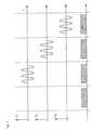
- Fig. 3shows four different measurement steps during the manipulation of the interventional device (and therefore the Faraday sensor).
- the static magnetic fieldis acting upon the sensor and the signal at the photo detector is used to determine the orientation of the device.
- a sinusoidally modulated waveformis applied to the magnetic field gradient in the first, the second and the third spatial direction.
- the photo detector signalis evaluated using the lock-in amplifier for signal analysis.
- TGGTerbium-Gallium-gamet
- a diode laser(DLS15, Linos, Germany) was used as a light source and the light was coupled into the crystal through an optical fibre (core diameter: 63 ⁇ m) and a polarising foil.
- a rotatable analyzerwas placed directly behind the crystal and the power of the transmitted light was measured far away from the sensor using again an optical fibre for light transmission and a photo detector (transmission type sensor).
- the senorbe integrated into an optical fibre and be operated in reflection mode, so that a single fibre can be used and the sensitivity is doubled. Furthermore, special gradient cycles for optical position detection must be incorporated into MRI pulse sequences.
Landscapes
- Physics & Mathematics (AREA)
- Engineering & Computer Science (AREA)
- Condensed Matter Physics & Semiconductors (AREA)
- General Physics & Mathematics (AREA)
- Power Engineering (AREA)
- Pathology (AREA)
- General Health & Medical Sciences (AREA)
- Health & Medical Sciences (AREA)
- Measuring Magnetic Variables (AREA)
- Investigating Or Analysing Materials By Optical Means (AREA)
- Eye Examination Apparatus (AREA)
- Container, Conveyance, Adherence, Positioning, Of Wafer (AREA)
- Electrical Discharge Machining, Electrochemical Machining, And Combined Machining (AREA)
Abstract

Description
- The present invention relates to a method and an apparatus for detecting the position andthe orientation of an interventional device, using a Faraday sensor.
- Modem interventional and surgical procedures aim to treat the affected tissue by causingminimal injury to healthy tissue structures. Special instruments are delivered to the targetregion via a minimal surgical opening and the affected tissue is treated.
- The target of the minimally invasive operation is often not directly visible for theinterventionist, thus the operations are done under imaging guidance. X-ray fluoroscopy,computed tomography, ultrasound and optical endoscopy are currently the most frequentlyused imaging methods. However, magnetic resonance imaging (MRI) is a state of the artimaging modality for medical diagnostics and it has potential to become a superiorguidance method. Knowing the accurate position of the instrument tip inside the patient isessential, since the surgeon should be able to accurately guide the instrument to the target.
- Within an MR-imaging apparatus, interventional device tracking has so far been doneeither by evaluating the change (gain or destruction) of the MR-signal at the position of theinterventional device or by attaching an electrical conductor or a high-frequency antenna tothe device.
- The change of MR-signal caused by the device itself can only be used to measure theposition of the device, if the device is positioned within the imaging frame. Furthermore, ifthe contrast between the device and its surroundings is too low, it cannot be detected.Visualisation of an interventional device could depend upon its being coated with an MRcontrast agent, or upon its effect on the MR image by nature of its chemical make-up.However, compounds and materials considered MR-compatible, and even MR contrast agents, can produce significant distortion artifacts that obscure the anatomy and physiologyof the imaged tissue. Initial attempts to visualise endovascular devices in MR imagingwere based on passive susceptibility artifacts produced by the device when exposed to theMR field. US 5,154,179 and US 4,989,608 disclose the incorporation of paramagneticmaterial into endovascular devices to make the devices visible under MR imaging.
- If the device is connected to an electrical conductor with one or more windings and if thesewindings are passed by a direct current, a local distortion of the magnetic field of the MR-imagingapparatus is caused. This distortion causes a local alteration of the MR image. Bytaking two MR images, one with and one without a direct current flowing through theconductor, the position of the interventional device can be determined by the difference ofthe signals in the two MR images. This method is described in US 5,868,674. Within themagnetic radio frequency field of the MR-imaging apparatus, electric coupling of thewires, which are used as a current supply for the electrical conductor can lead to severeheating under certain circumstances. If the heat is not dissipated, it might result in thedestruction of the device and it could be hazardous to the patient.
- Another possibility for measuring the position of the interventional device is theapplication of a high-frequency antenna, which is attached to the device. This antenna istuned to the resonance frequency of the MR-imaging apparatus. Therefore, the antenna isnot compatible to all MR imagers. Furthermore, dangerous RF-heating can take place andthe MR technique has to be adapted to this kind of device tracking.
- Exemplary of methods for active MR visualisation of implanted medical devices is US5,211,165, which discloses an MR tracking system for a catheter based on transmit/receivemicrocoils positioned near the end of the catheter by which the position of the device canbe tracked and localised. US 5,375,596 discloses a method for locating catheters and othertubular medical devices implanted in the human body using an integrated system of wiretransmitters and receivers. US 4,572,198 also provides for conductive elements, such aselectrode wires, for systematically disturbing the magnetic field in a defined portion of acatheter to yield increased MR visibility of that region of the catheter. However, thepresence of conductive elements in the catheter also introduces increased electronic noiseand the possibility of Ohmic heating, and these factors have the overall effect of degradingthe quality of the MR image and raising concerns about the patient's safety. US 5,882,305therefore replaces long lead wires, which can cause heating during MR imaging and maydistort an MR image, by at least one optical fibre. Consequently, electrical signals have tobe converted into modulated optical signals and vice versa by two transducer circuits.
- Another possible way of finding the position of an interventional device is to localise itindependently of the MR imaging, by using several cameras and light-emitting orreflecting reference marks. For this technique, a free field of view between the referencemarks and the cameras is required. Unfortunately, the field of view is very limited whenthe interventional device is inside a patient's body and when the MR-imaging apparatus isclosed.
- Accordingly, it is the object of the present invention to provide an improved method andapparatus for detecting the position and the orientation of an interventional device, whichovercome the drawbacks mentioned above.
- In accordance with the object of the present invention, there is provided a method formeasuring the position and the orientation of an interventional device within a magneticresonance imaging apparatus, the magnetic resonance imaging apparatus providing a staticmagnetic field B0, and magnetic field gradients with known magnetic flux densities anddirections, comprising the steps of
- (A) attaching a Faraday sensor to the interventional device, the Faraday sensor beingconnected to an optical measuring device,
- (B) using the optical measuring device for measuring the rotation of the plane ofpolarisation of linearly polarised light in the Faraday sensor, while exposing theinterventional device
- (i) to the static magnetic field B0 and
- (ii) to the field gradients in all three directions of space in addition to the staticmagnetic field B0 and
- (C) determining the position and the orientation of the interventional device byevaluating the measured rotation of the plane of polarisation of the linearlypolarised light.
- The method according to the invention takes advantage of the magnetic fields provided bya magnetic resonance (MR) imaging apparatus. Compared to X-ray systems, which workwith significant levels of radiation, MR does not utilise ionising radiation and there are noknown long-term adverse effects on biological tissues from MR, as used in clinical MRimaging environment.
- In step A) of the method according to the invention, a Faraday sensor is attached to theinterventional device. A Faraday sensor uses the Faraday effect, which consists in therotation of the plane of polarisation of a light beam by a magnetic field. The magnitude ofrotation (rotation angle Φ) depends upon the strength of the magnetic field (magnetic fluxdensity B), the length of the transmitting
substance 1 and Verdet constant V, which is aproperty of the transmitting substance, its temperature and the frequency of the transmittedlight. If the light path and the direction of the applied magnetic field are parallel, the planeof polarisation is rotated according to the following form:V B 1. - If the light path is oriented in an angle α with respect to the direction of the magnetic field,the rotation angle of the plane of polarisation is
V B 1 cosα. - Therefore, by measuring the angle of rotation Φ and if V and 1 are known (and α = 0), themagnetic flux density of the magnetic field can be determined. Furthermore, by measuringthe angle of rotation Φ and if V, B and 1 are known, the angle α can be determined. Thepresent invention profits of these correlations in order to measure the local magnetic fieldand thereby the position and orientation of the interventional device, to which the Faradaysensor is attached.
- For measuring Φ, an active material, typically a crystal, is placed in a light beam between apolarizer and an analyzer and Φ is given by the relative angle between the polarizer and theanalyzer at maximum light transmission. At a constant angle between the polarizer and theanalyzer, the angle of rotation can be determined by measuring the light intensitytransmitted by the analyzer, which depends upon the rotation angle Φ. Changes in themagnetic field result in a modulation of the transmitted light and can be measured e.g.using a fast photo detector. The polarizer, the analyzer and the fast photo detector can bepart of the optical measuring device of the present invention.
- One advantage of using a Faraday sensor for interventional device tracking is that it doesnot contain any conducting material. As a result, a dangerous heating of the position sensoris avoided.
- In step (B) of the method according to invention, the rotation of the plane of polarisation oflinearly polarised light in the Faraday sensor is measured with the help of the opticalmeasuring device. As mentioned above, the angle of rotation is a function of the strengthof the magnetic field. As a result, measuring the angle of rotation means measuring thestrength of the magnetic field, if all other variables are known. According to the presentinvention, the magnetic resonance imaging apparatus provides defined magnetic fields, thestrength and direction of which are known and are different at every point of themeasurement space. Therefore, the Faraday sensor can be localised by determining themagnetic field strength at its position.
- The interventional device (together with the Faraday sensor) is exposed to a static andpreferably homogeneous magnetic field B0 (step B) i)) in order to determine its orientation.If the light path inside the Faraday sensor is not parallel to the lines of electric flux of thismagnetic field, the rotation of the plane of polarisation is different than with the light pathand the lines of electric flux being parallel (see above formula). The magnetic field is thesame for any position of the Faraday sensor within the static and homogeneous magneticfield B0. Consequently, the angle of rotation Φ is not dependent upon the position of theFaraday sensor, but only upon the angle α between the direction of the magnetic field andthe light path within the sensor.
- In another step (B)ii)), the interventional device is exposed to field gradients in all threedirections of space in addition to the static and preferably homogeneous magnetic field B0.The magnetic field gradient is a variation in the magnetic field with respect to position. Byapplying field gradients in all three directions (at the same time or one after the other), thethree coordinates giving the position of the Faraday sensor (and the interventional device)can be determined. The steps (B) (i) and (B) (ii) can also be carried out in reverse order.
- One advantage of the present invention is that no visual contact with the Faraday sensor isnecessary. Furthermore, localising the sensor is not dependent upon MR imaging and thecorresponding image formation, since it is carried out only by determining the localmagnetic field at the position of the sensor with the help of field gradients.
- In one preferred embodiment of the present invention, the Faraday sensor is a reflectiontype sensor. In this kind of sensor, the light passes through the active material (e.g. thecrystal) of the Faraday sensor, is reflected and passes through the active material again inthe other direction. The direction of rotation of the plane of polarisation is the same forboth paths of the light. Therefore, if the same beam of light is reflected back and forth through the active medium, the rotation of its plane of polarisation is increased each time.The reflection of the light beam can either take place at a mirror behind the active mediumof the Faraday sensor or at the end surface of the active medium itself. The reflection typesensor is advantageous because of its possible miniaturisation, allowing the Faraday sensorto be integrated easily into very small interventional devices.
- The magnetic resonance imaging apparatus provides the magnetic fields for MR imagingand for the method according to the invention. The magnetic fields applied for MRimaging, particularly the field gradients, are usually very complex. The magnetic fieldsused for determining the position and the orientation of an interventional device can bechosen much simpler, in order to keep the evaluation of the measured data (in step C))simple.
- In a preferred embodiment of the present invention, the magnetic fields provided by themagnetic resonance imaging apparatus are used for both, the MR imaging and themeasurement of the position and the orientation of the interventional device. By using thesame magnetic fields for both purposes, the time for getting MR images and theinformation about the position and orientation of the interventional device is reduced. Longscan times limit the applicability of MR-imaging techniques to the general patientpopulation. In particular, long scan times lead to artifacts in the MR images due toinvoluntary patient movements and motion of the interventional device. Therefore the scantime should be reduced as much as possible.
- In a preferred embodiment of the present invention, an image of the interventional deviceis superimposed upon independently acquired diagnostic images at the position asdetermined in step C) of the method according to the invention. The position of theinterventional device (and possibly its orientation) is displayed on display means bysuperposition of a graphic symbol on a conventional MR image. In alternativeembodiments of the invention, a graphic symbol representing the interventional device issuperimposed on diagnostic images obtained with other imaging systems such as acomputer tomography (CT) scanner, an ultrasound scanner or a positron emissiontomography (PET) system. Other embodiments of the invention display the position andthe orientation of the interventional device numerically or as a graphic symbol withoutreference to a medical diagnostic image.
- Preferably the interventional device, the position and orientation of which are measuredaccording to the present invention, is a guide wire, a catheter, an endoscope, a laparoscope, a biopsy needle, surgical implement, therapy delivery implement, an intravascular catheter,a radiofrequency ablation device, a cryo-cooling device or a similar device.
- In a preferred embodiment of the present invention the Faraday sensor is aligned within astatic homogeneous magnetic field B0 (B0 as used in step (B)) prior to its use for themethod according to the invention. In this context, aligning means setting a particularangle of orientation α between the direction of the magnetic field and the light path withinthe sensor, e.g. an angle of 0°. The Faraday rotation angle cal is measured with the alignedsensor and stored. In step (B)(i) of the method according to the invention (for exampleduring an interventional procedure) the rotation angle 0 within the static homogeneousmagnetic field B0 in the absence of field gradients is determined. From the phasedifference 0- cal the actual orientation angle α is computed.
- Preferably in step (B)(ii) of the method according to the invention the interventional deviceis exposed to at least one magnetic field gradient in each direction of space (x,y,z). In amagnetic resonance tomography apparatus the field gradient G is typically designed tomodulate the component of the magnetic flux parallel to the static magnetic field B0:
- The position of the Faraday sensor (and the interventional device) is then calculated by thedifference of the angle of rotation of linearly polarised light caused by the differentmagnetic field gradients x,y,z and the rotation angle measured without the presence of thegradients 0:
- A measurement of the position and orientation of the sensor therefore requires themeasurement of four Faraday rotation angles (0, x, y, z) and an initial calibration of thesensor (cal).
- In a further preferred embodiment of the present invention the relative angle of rotation isincreased using a minimum of two magnetic field gradients with opposite polarities in eachspatial direction. The two gradients are applied successively and the phase difference ismeasured.
- In another preferred embodiment of the present invention, the optical measuring deviceuses a lock-in technique for measuring the rotation of the plane of polarisation of thelinearly polarised light in the Faraday sensor caused by the magnetic field gradients. Theangle of rotation of the plane of polarisation of the linearly polarised light is preferablydetermined by measuring the light intensity of the linearly polarised light after passingthrough an analyzer. If the magnetic field, to which the Faraday sensor is exposed, iscomposed of a strong static magnetic field B0 and a small field gradient, the angle ofrotation is mainly influenced by the strong static magnetic field. The small field gradientsgenerate the position information, however, the small position signal is obscured by noisein the received signal. One of the most useful devices for improving the signal-to-noiseratio is the lock-in amplifier. A lock-in amplifier takes a periodic reference signal and anoisy input signal and extracts only that part of the signal whose frequency and phasematch the reference. Therefore, the signal to be measured has to be modulated (e.g.chopped) with the reference frequency. For the present invention, the field gradients aremodulated with a reference frequency, resulting in a modulated intensity signal of thelinearly polarised light after passing through the Faraday sensor and the analyzer.
- Furthermore, the present invention provides a method for measuring the position and/or theorientation of an object in a measurement space by connecting at least one Faraday sensorto the object, exposing the object to at least one magnetic field with a known direction anda known magnetic flux density, the magnetic flux density being different in every point ofthe measurement space, measuring the magnetic flux density with the Faraday sensor andassigning the measured magnetic flux density to the position and/or the orientation of theobject. The method of detecting the position and orientation of an object within a definedmagnetic field with the help of a Faraday sensor is not limited to medical applicationswithin an MR-imaging apparatus. It can also be used for non-medical applications withinan MR-scanner or for position detection in a known magnetic field, which is not providedby an MR-imaging apparatus. Examples for non-medical applications within an MR-scannerare materials science investigations with an MR-independent position signal (e.g.studies on parmesan cheese). Position detection with a known magnetic field, which is notprovided by an MR-imaging apparatus, can be carried out in a room with special coils forgenerating the magnetic fields for spatial encoding.
- Furthermore, the present invention provides an apparatus for detecting the position and theorientation of an interventional device using the method according to the invention,containing at least one Faraday sensor and at least one device for providing a definedmagnetic field.
- The present invention may be best understood by reference to the following description inconjunction with the accompanying drawing in which:
- Fig. 1a
- is a schematic drawing showing an optical measuring device with atransmission type Faraday sensor suitable for the present invention,
- Fig. 1b
- is a schematic drawing showing an optical measuring device with areflection type Faraday sensor suitable for the present invention,
- Fig. 1c
- is a schematic drawing showing an optical measuring device with atransmission type Faraday sensor with an etalon suitable for the presentinvention,
- Fig. 2
- is a schematic illustration showing an optical measuring device with atransmission type Faraday sensor being suitable for the present inventionand
- Fig. 3
- is a timing diagram showing the consecutive measurement steps todetermine the orientation and the position of the sensor.
- The Faraday sensor as shown in fig. 1a contains a magneto-optically active medium in theform of a
crystal 1. Within a magnetic field the polarisation of a light beam is rotated whenthe beam is traversing thecrystal 1. The rotation angle at the end of thecrystal 1 dependsupon the length L of the active material, the Verdet constant and the magnetic fieldstrength. To measure the rotation angle, thecrystal 1 is placed between apolarizer 3 and ananalyzer 4. Thepolarizer 3 and theanalyzer 4 are formed by polarisation foils, which arearranged at a constant angle to each other. Theoptical fibre 5 is used to couple light, whichis emitted by alight source 7, into thecrystal 1, after having passed thepolarizer 3. Asecondoptical fibre 6 is used to transmit the light beam coming out of the Faraday sensorto a detector (not shown) for measuring the light intensity. The Faraday sensor as shown infig. 1a is a transmission type sensor. The light beam passes through this sensor only in onedirection. - In an alternative implementation the Faraday sensor is constructed as a reflection typesensor as shown in fig. 1b. The reflection type sensor has the advantage that the same
optical fibre 5 can be used to transmit the light from thelight source 7 to the sensor and to guide the reflected light to an external detector (not shown). Furthermore, the rotationangle in a reflection type sensor is doubled as compared to a transmission type sensor ofthe same length L due to the doubled optical path length. Therefore, amirror 9 is attachedto the end of thecrystal 1 to reflect the light coming from thelight source 7 passing inforward direction through thepolarizer 3 and thecrystal 1. The light reflected bymirror 9is passing in backward direction through thecrystal 1 and thepolarizer 3, which is nowacting as ananalyzer 4, and is guided through thefibre 5 to abeam splitter 2. At thebeamsplitter 2, the reflected light beam is separated from theincident light beam 8. Thereflectedlight beam 19 is then transmitted to a detector (not shown). - In an alternative implementation the Faraday sensor is constructed as an etalon type sensoras shown in fig. 1c. The etalon type sensor is a modification of the reflection type sensorshown in fig. 1b where a second,
semi-transparent mirror 11 is placed between thepolarizer 3 and thecrystal 1 in addition to the reflectingfirst mirror 10 at the end of thecrystal 1. - In summary, the optical measuring device, which is suitable for the present inventionpreferably comprises a
light source 7, apolarizer 3, ananalyzer 4 and a photo detector. Thelight source 7 is preferably a laser, especially a diode laser. Since the Verdet constantdepends upon the frequency of the light passing through the magneto-optically activematerial, the method according to the present invention should be operated with amonochromatic light source. - In a preferred embodiment of the present invention, the
light source 7 is an intensity-stabilizedlight source in order to avoid intensity fluctuations of the light beam, whichwould cause errors of measurement. Another possibility of eliminating the unwanted effectof intensity fluctuations of the light beam emitted by thelight source 7 would bedecoupling part of the light beam to be used in the Faraday sensor without its plane ofpolarisation being rotated in the Faraday sensor, the decoupled light beam serving as areference beam. - The Faraday sensor is preferably connected to the optical measuring device by at least one
optical fibre optical fibres light source 7 and the photo detector canbe placed outside of the magnetic fields, advantageously avoiding any influence of thefields on the functioning of these devices. The Faraday sensor preferably comprises acrystal 1 containing at least one of the following magneto-optically active materials:terbium-gallium-gamet or rare earth (III) aluminum garnets (cf. Rubinsetin CB, Van Uitert LG, Grodkiewicz WH: Magneto-optical properties of rare earth (III) aluminum garnets, J.Appl. Phys. 35, 3069-70 (1964)). - Fig. 2 shows a transmission type Faraday sensor, which is suitable for the presentinvention, being placed within a static magnetic field and in magnetic field gradients andconnected to a signal evaluation unit. A
light source 7 emits a beam of light, which passesthrough anoptical fibre 5. The light is coupled into apolarizer 3 and acrystal 1 whichturns its plane of polarisation in the presence of magnetic fields created by amagnet 13 andby magnetic field gradient coils 12. The transmitted light is passed through ananalyzer 4 atthe end of thecrystal 1. The close proximity ofpolarizer 3 andanalyzer 4 to thecrystal 1ensures that the plane of polarisation is not rotated additionally within theoptical fibres analyzer 4 is coupled into a secondoptical fibre 6 which guides the light to thephotodetector 14. Thephoto detector 14 creates a signal proportional to the intensity of the lighthaving passed the Faraday sensor. - For measuring the orientation of the sensor with respect to the static magnetic field createdby the
magnet 13 in the absence of magnetic field gradients created by the gradient coils12, the signal amplitude measured by thephoto detector 14 is compared with the signalamplitude measured with the aligned sensor, which is oriented parallel to the staticmagnetic field. - For measuring the position of the Faraday sensor a magnetic field gradient in one spatialdirection created by the gradient coils 12 is applied. Preferably the gradient amplitude ismodulated in the form of a sine wave. The modulated gradient field creates an intensitymodulation of the light beam passing through the sensor. To evaluate the amplitude ofmodulation, the signal output of the
photo detector 14 is passed to a lock-inamplifier 18.To eliminate unwanted effects of signal fluctuations, the photo detector signal is passedthrough a low-pass filter 16 to determine a reference signal which does not show themodulation created by the gradients. This reference signal is used for normalization of thelock-inamplifier signal 18. The photo detector output signal is also passed to the lock-inamplifier 18 through a high-pass filter 15. The high-pass filter 15 is chosen so that themodulation frequency created by the gradient coils 12 is not lost in the filtering process.This signal is then compared in the lock-inamplifier 18 with the modulation signal of thegradients provided by thegradient controller 17. The demodulated and normalized output signal of the lock-inamplifier 18 is a measure of the position along the direction of theapplied gradient. - Fig. 3 shows four different measurement steps during the manipulation of theinterventional device (and therefore the Faraday sensor). During a first time period only thestatic magnetic field is acting upon the sensor and the signal at the photo detector is used todetermine the orientation of the device. In the next three following steps a sinusoidallymodulated waveform is applied to the magnetic field gradient in the first, the second andthe third spatial direction. During each of these time periods the photo detector signal isevaluated using the lock-in amplifier for signal analysis.
- As the magneto-optically active material for the position sensor a 7.5 mm-long crystal ofTerbium-Gallium-gamet (TGG) was chosen, which offers a high Verdet constant of about7 deg/T/mm at λ = 675 nm. A diode laser (DLS15, Linos, Germany) was used as a lightsource and the light was coupled into the crystal through an optical fibre (core diameter: 63µm) and a polarising foil. A rotatable analyzer was placed directly behind the crystal andthe power of the transmitted light was measured far away from the sensor using again anoptical fibre for light transmission and a photo detector (transmission type sensor). Severaldifferent experiments were carried out: (a) The sensor was placed at the patient table of acommercial whole body 1.5 T MR scanner (Siemens Magnetom Symphony) and theFaraday rotation was measured with the sensor as a function of z-position and compared tothe magnetic flux measurement of a Hall detector. (b) At the magnet's iso-center the sensorwas rotated relative to the B0-field direction and the change in Faraday rotation wasassessed. (c) Trapezodial gradients of variable duration (1-2 ms) and amplitude (20 and 30mT/m) were applied at different positions in the gradient field and the change in lighttransmission was detected with a lock-in amplifier, which compared the gradient controlsignal with the signal of the fast photo detector. Since the output power of the laser diodewas not constant over the measurement period, the detected signal was normalised to thelow frequency component of the laser diode signal.
- The magnetic field measurement with the optical sensor showed that the response of thesensor was linear up to B0 = 1.5 T. At this field strength a total rotation angle of 65.8° wasmeasured, which corresponds to a measured Verdet constant of 5.9 deg/T/mm. Theexpected cosine-law for the rotation against the main magnetic field Φ = V L B cos(α)could be reproduced. The normalised demodulated lock-in amplifier signal Un showed a linear dependency of the position of the sensor. For a gradient strength of G = 30 mT/m asensitivity of (0.31±0.02) x 10-3 was achieved (fig. 2) so that with this set-up the precisionof the localisation is about 1.5 cm. With the current proto-type sensor both position andone orientation angle can be measured. Using this technique e.g. in an intravascularcatheter demands the sensor be integrated into an optical fibre and be operated in reflectionmode, so that a single fibre can be used and the sensitivity is doubled. Furthermore, specialgradient cycles for optical position detection must be incorporated into MRI pulsesequences.
- 1
- crystal
- 2
- beam splitter
- 3
- polarizer
- 4
- analyzer
- 5
- first optical fibre
- 6
- second optical fibre
- 7
- light source
- 8
- incident light beam
- 9
- mirror
- 10
- first mirror
- 11
- second mirror
- 12
- gradient coils
- 13
- magnet
- 14
- photo detector
- 15
- high pass filter
- 16
- low pass filter
- 17
- gradient controller
- 18
- lock-in amplifier
- 19
- reflected light beam
Claims (13)
- A method for measuring the position and the orientation of an interventional devicewithin a magnetic resonance imaging apparatus, the magnetic resonance imagingapparatus providing a static magnetic field B0 and magnetic field gradients withknown magnetic flux densities and directions, comprising the steps of(A) attaching a Faraday sensor to the interventional device, the Faraday sensorbeing connected to an optical measuring device,(B) using the optical measuring device for measuring the rotation of the plane ofpolarisation of linearly polarised light in the Faraday sensor, while exposingthe interventional deviceand(i) to the static magnetic field B0 and(ii) to the field gradients in all three directions of space in addition to thestatic magnetic field B0(C) determining the position and the orientation of the interventional device byevaluating the measured rotation of the plane of polarisation of the linearlypolarised light.
- The method as claimed in claim 1, wherein the Faraday sensor is a reflection typesensor, an etalon type sensor or a transmission type sensor.
- The method as claimed in claim 1 or 2, wherein the magnetic fields provided by themagnetic resonance imaging apparatus are used for both, the MR imaging and themeasurement of the position and the orientation of the interventional device.
- The method as claimed in one of claims 1 to 3, wherein an image of theinterventional device is superimposed upon independently acquired medicaldiagnostic images at the position as determined in step (C).
- The method as claimed in one of claims 1 to 4, wherein the optical measuring devicecomprises a light source (7), a polarizer (3), an analyzer (4) and at least one photodetector (14).
- The method as claimed in claim 5, wherein the light source (7) is a diode laser.
- The method as claimed in one of claims 1 to 6, wherein the Faraday sensor isconnected to the optical measuring device by at least one optical fibre (5, 6).
- The method as claimed in one of claims 1 to 7, wherein the Faraday sensorcomprises a crystal (1) containing at least one of the following magneto-opticallyactive materials: terbium-gallium-gamet or rare earth aluminum garnets.
- The method as claimed in one of claims 1 to 8, wherein the interventional device is aguide wire, a catheter, an endoscope, a laparoscope, a biopsy needle, surgicalimplement, therapy delivery implement, an intravascular catheter, a radiofrequencyablation device or a cryo-cooling device.
- The method as claimed in one of claims 1 to 9, wherein the interventional device isexposed to at least one magnetic field gradient in each direction of space in stepB)ii).
- The method as claimed in one of claims 1 to 10, wherein the optical measuringdevice uses a lock-in technique for measuring the rotation of the plane of polarisationof the linearly polarised light in the Faraday sensor, caused by the magnetic fieldgradients.
- A method for measuring the position and/or the orientation of an object in ameasurement space by connecting at least one Faraday sensor to the object, exposingthe object to at least one magnetic field with a known direction and a knownmagnetic flux density, the magnetic flux density being different in every point of themeasurement space, measuring the magnetic flux density with the Faraday sensorand assigning the measured magnetic flux density to the position and/or theorientation of the object.
- An apparatus for detecting the position and the orientation of an interventionaldevice using the method as claimed in one of claims 1 to 12 containing at least oneFaraday sensor and at least one device for providing a defined magnetic field.
Priority Applications (4)
| Application Number | Priority Date | Filing Date | Title |
|---|---|---|---|
| DE60314493TDE60314493T2 (en) | 2003-01-10 | 2003-01-10 | Device for determining the location and orientation of an invasive device |
| EP03000554AEP1437601B1 (en) | 2003-01-10 | 2003-01-10 | Apparatus for detecting the position and the orientation of an invasive device |
| AT03000554TATE365334T1 (en) | 2003-01-10 | 2003-01-10 | DEVICE FOR DETERMINING THE LOCATION AND ORIENTATION OF AN INVASIVE DEVICE |
| US10/754,625US7239400B2 (en) | 2003-01-10 | 2004-01-12 | Method and apparatus for detecting the position and the orientation of an interventional device |
Applications Claiming Priority (1)
| Application Number | Priority Date | Filing Date | Title |
|---|---|---|---|
| EP03000554AEP1437601B1 (en) | 2003-01-10 | 2003-01-10 | Apparatus for detecting the position and the orientation of an invasive device |
Publications (2)
| Publication Number | Publication Date |
|---|---|
| EP1437601A1true EP1437601A1 (en) | 2004-07-14 |
| EP1437601B1 EP1437601B1 (en) | 2007-06-20 |
Family
ID=32479917
Family Applications (1)
| Application Number | Title | Priority Date | Filing Date |
|---|---|---|---|
| EP03000554AExpired - LifetimeEP1437601B1 (en) | 2003-01-10 | 2003-01-10 | Apparatus for detecting the position and the orientation of an invasive device |
Country Status (4)
| Country | Link |
|---|---|
| US (1) | US7239400B2 (en) |
| EP (1) | EP1437601B1 (en) |
| AT (1) | ATE365334T1 (en) |
| DE (1) | DE60314493T2 (en) |
Cited By (4)
| Publication number | Priority date | Publication date | Assignee | Title |
|---|---|---|---|---|
| EP1785739A1 (en) | 2005-11-14 | 2007-05-16 | DKFZ Deutsches Krebsforschungszentrum | An elongate, segmented, RF safe device for use with an MRI machine |
| CN102607424A (en)* | 2012-03-14 | 2012-07-25 | 董建增 | Photoelectric detection device for conduit movement |
| WO2012143540A1 (en)* | 2011-04-22 | 2012-10-26 | Eidgenössische Technische Hochschule (ETH) | Determining positions of a magnetic field probe in a magnetic resonance measurement |
| CN105640552A (en)* | 2014-12-02 | 2016-06-08 | 精工爱普生株式会社 | Magnetic field measurement method and magnetic field measurement apparatus |
Families Citing this family (17)
| Publication number | Priority date | Publication date | Assignee | Title |
|---|---|---|---|---|
| US20090281383A1 (en)* | 2005-09-08 | 2009-11-12 | Rao Papineni | Apparatus and method for external fluorescence imaging of internal regions of interest in a small animal using an endoscope for internal illumination |
| US8203132B2 (en)* | 2005-09-08 | 2012-06-19 | Carestream Health, Inc. | Apparatus and method for imaging ionizing radiation |
| US20100220836A1 (en) | 2005-09-08 | 2010-09-02 | Feke Gilbert D | Apparatus and method for multi-modal imaging |
| US8660631B2 (en)* | 2005-09-08 | 2014-02-25 | Bruker Biospin Corporation | Torsional support apparatus and method for craniocaudal rotation of animals |
| WO2008065196A2 (en)* | 2006-11-30 | 2008-06-05 | North Sensor A/S | Faraday effect current sensor |
| JP5388472B2 (en)* | 2008-04-14 | 2014-01-15 | キヤノン株式会社 | A control device, an X-ray imaging system, a control method, and a program for causing a computer to execute the control method. |
| WO2010144402A2 (en) | 2009-06-08 | 2010-12-16 | Surgivision, Inc. | Mri-guided surgical systems with preset scan planes |
| CN102625670B (en) | 2009-06-16 | 2015-07-15 | 核磁共振成像介入技术有限公司 | MRI-guided devices and MRI-guided interventional systems that can track and generate dynamic visualizations of the devices in near real time |
| US8970217B1 (en) | 2010-04-14 | 2015-03-03 | Hypres, Inc. | System and method for noise reduction in magnetic resonance imaging |
| GB201112161D0 (en)* | 2011-07-15 | 2011-08-31 | Qinetiq Ltd | Portal monitoring |
| EP2549284A1 (en) | 2011-07-21 | 2013-01-23 | Koninklijke Philips Electronics N.V. | Position marker for use in an MRI apparatus |
| FR3002046B1 (en)* | 2013-02-14 | 2015-04-03 | Univ Claude Bernard Lyon | METHOD AND MEASURING DEVICE FOR MAGNETIC RESONANCE APPLICATIONS |
| US11344382B2 (en)* | 2014-01-24 | 2022-05-31 | Elucent Medical, Inc. | Systems and methods comprising localization agents |
| US9730764B2 (en) | 2015-10-02 | 2017-08-15 | Elucent Medical, Inc. | Signal tag detection components, devices, and systems |
| US9987097B2 (en) | 2015-10-02 | 2018-06-05 | Elucent Medical, Inc. | Signal tag detection components, devices, and systems |
| CN109890300B (en)* | 2016-08-12 | 2023-02-28 | 艾鲁森特医疗股份有限公司 | Surgical device guidance and monitoring devices, systems, and methods |
| US10278779B1 (en) | 2018-06-05 | 2019-05-07 | Elucent Medical, Inc. | Exciter assemblies |
Citations (5)
| Publication number | Priority date | Publication date | Assignee | Title |
|---|---|---|---|---|
| US5318025A (en)* | 1992-04-01 | 1994-06-07 | General Electric Company | Tracking system to monitor the position and orientation of a device using multiplexed magnetic resonance detection |
| US5592939A (en)* | 1995-06-14 | 1997-01-14 | Martinelli; Michael A. | Method and system for navigating a catheter probe |
| US6223066B1 (en)* | 1998-01-21 | 2001-04-24 | Biosense, Inc. | Optical position sensors |
| US20020058868A1 (en)* | 2000-06-05 | 2002-05-16 | Tsutomu Hoshino | Interventional MR imaging with detection and display of device position |
| WO2002086526A1 (en)* | 2001-04-21 | 2002-10-31 | Koninklijke Philips Electronics N.V. | Optical mr signal transmission |
Family Cites Families (11)
| Publication number | Priority date | Publication date | Assignee | Title |
|---|---|---|---|---|
| US4572198A (en)* | 1984-06-18 | 1986-02-25 | Varian Associates, Inc. | Catheter for use with NMR imaging systems |
| US5154179A (en)* | 1987-07-02 | 1992-10-13 | Medical Magnetics, Inc. | Device construction and method facilitating magnetic resonance imaging of foreign objects in a body |
| US4989608A (en)* | 1987-07-02 | 1991-02-05 | Ratner Adam V | Device construction and method facilitating magnetic resonance imaging of foreign objects in a body |
| US5149962A (en)* | 1991-06-03 | 1992-09-22 | Simmonds Precision Products, Inc. | Proximity detector using faraday effect and bidirectional transmission |
| US5211165A (en)* | 1991-09-03 | 1993-05-18 | General Electric Company | Tracking system to follow the position and orientation of a device with radiofrequency field gradients |
| US5375596A (en)* | 1992-09-29 | 1994-12-27 | Hdc Corporation | Method and apparatus for determining the position of catheters, tubes, placement guidewires and implantable ports within biological tissue |
| DE69634035T2 (en)* | 1995-11-24 | 2005-12-08 | Koninklijke Philips Electronics N.V. | SYSTEM FOR IMAGING BY MAGNETIC RESONANCE AND CATHETER FOR PROCEDURE PROCEDURE |
| US5719497A (en)* | 1996-05-09 | 1998-02-17 | The Regents Of The University Of California | Lensless Magneto-optic speed sensor |
| US5730134A (en)* | 1996-09-09 | 1998-03-24 | General Electric Company | System to monitor temperature near an invasive device during magnetic resonance procedures |
| US6498654B1 (en)* | 1999-06-11 | 2002-12-24 | Harco Laboratories, Inc. | Optical proximity detector |
| US7183765B2 (en)* | 2003-06-26 | 2007-02-27 | The Regents Of The University Of California | Micro-position sensor using faraday effect |
- 2003
- 2003-01-10DEDE60314493Tpatent/DE60314493T2/ennot_activeExpired - Lifetime
- 2003-01-10EPEP03000554Apatent/EP1437601B1/ennot_activeExpired - Lifetime
- 2003-01-10ATAT03000554Tpatent/ATE365334T1/ennot_activeIP Right Cessation
- 2004
- 2004-01-12USUS10/754,625patent/US7239400B2/ennot_activeExpired - Fee Related
Patent Citations (5)
| Publication number | Priority date | Publication date | Assignee | Title |
|---|---|---|---|---|
| US5318025A (en)* | 1992-04-01 | 1994-06-07 | General Electric Company | Tracking system to monitor the position and orientation of a device using multiplexed magnetic resonance detection |
| US5592939A (en)* | 1995-06-14 | 1997-01-14 | Martinelli; Michael A. | Method and system for navigating a catheter probe |
| US6223066B1 (en)* | 1998-01-21 | 2001-04-24 | Biosense, Inc. | Optical position sensors |
| US20020058868A1 (en)* | 2000-06-05 | 2002-05-16 | Tsutomu Hoshino | Interventional MR imaging with detection and display of device position |
| WO2002086526A1 (en)* | 2001-04-21 | 2002-10-31 | Koninklijke Philips Electronics N.V. | Optical mr signal transmission |
Cited By (5)
| Publication number | Priority date | Publication date | Assignee | Title |
|---|---|---|---|---|
| EP1785739A1 (en) | 2005-11-14 | 2007-05-16 | DKFZ Deutsches Krebsforschungszentrum | An elongate, segmented, RF safe device for use with an MRI machine |
| WO2012143540A1 (en)* | 2011-04-22 | 2012-10-26 | Eidgenössische Technische Hochschule (ETH) | Determining positions of a magnetic field probe in a magnetic resonance measurement |
| US9915713B2 (en) | 2011-04-22 | 2018-03-13 | Universitat Zurich | Determining positions of a magnetic field probe in a magnetic resonance measurement |
| CN102607424A (en)* | 2012-03-14 | 2012-07-25 | 董建增 | Photoelectric detection device for conduit movement |
| CN105640552A (en)* | 2014-12-02 | 2016-06-08 | 精工爱普生株式会社 | Magnetic field measurement method and magnetic field measurement apparatus |
Also Published As
| Publication number | Publication date |
|---|---|
| DE60314493D1 (en) | 2007-08-02 |
| US7239400B2 (en) | 2007-07-03 |
| US20040199067A1 (en) | 2004-10-07 |
| ATE365334T1 (en) | 2007-07-15 |
| EP1437601B1 (en) | 2007-06-20 |
| DE60314493T2 (en) | 2008-02-21 |
Similar Documents
| Publication | Publication Date | Title |
|---|---|---|
| EP1437601B1 (en) | Apparatus for detecting the position and the orientation of an invasive device | |
| EP0722290B1 (en) | Magnetic determination of position and orientation | |
| JP3854667B2 (en) | Magnetic resonance system and magnetic resonance imaging and tracking system | |
| US7650178B2 (en) | Magnetic field sensor-based navigation system to track MR image-guided interventional procedures | |
| US5882304A (en) | Method and apparatus for determining probe location | |
| US7162293B2 (en) | MR arrangement for localizing a medical instrument | |
| US20080033278A1 (en) | System and method for tracking medical device using magnetic resonance detection | |
| JP2008516640A (en) | Magnetic resonance markers based on position and orientation probes | |
| WO2011028505A1 (en) | Techniques for correcting temperature measurement in magnetic resonance thermometry | |
| EP1664819B1 (en) | Process for locating a medical instrument with a microcoil | |
| US20040116801A1 (en) | Optical mr signal transmission | |
| Bock et al. | A Faraday effect position sensor for interventional magnetic resonance imaging | |
| Thörmer et al. | Simultaneous 3D localization of multiple MR-visible markers in fully reconstructed MR images: proof-of-concept for subsecond position tracking | |
| JP2002528214A (en) | Target inspection equipment | |
| JPS6343650A (en) | Magnetic resonance apparatus | |
| JP2005110865A (en) | Treatment instrument for image guide treatment and magnetic resonance imaging device | |
| Vahala | Methods for interventional magnetic resonance imaging | |
| Zhang | Active interventional device guidance using Magnetic Resonance Imaging | |
| AU6442199A (en) | Magnetic determination of position and orientation |
Legal Events
| Date | Code | Title | Description |
|---|---|---|---|
| PUAI | Public reference made under article 153(3) epc to a published international application that has entered the european phase | Free format text:ORIGINAL CODE: 0009012 | |
| AK | Designated contracting states | Kind code of ref document:A1 Designated state(s):AT BE BG CH CY CZ DE DK EE ES FI FR GB GR HU IE IT LI LU MC NL PT SE SI SK TR | |
| AX | Request for extension of the european patent | Extension state:AL LT LV MK RO | |
| 17P | Request for examination filed | Effective date:20041203 | |
| AKX | Designation fees paid | Designated state(s):AT BE BG CH CY CZ DE DK EE ES FI FR GB GR HU IE IT LI LU MC NL PT SE SI SK TR | |
| 17Q | First examination report despatched | Effective date:20060320 | |
| GRAP | Despatch of communication of intention to grant a patent | Free format text:ORIGINAL CODE: EPIDOSNIGR1 | |
| RTI1 | Title (correction) | Free format text:APPARATUS FOR DETECTING THE POSITION AND THE ORIENTATION OF AN INVASIVE DEVICE | |
| GRAS | Grant fee paid | Free format text:ORIGINAL CODE: EPIDOSNIGR3 | |
| GRAA | (expected) grant | Free format text:ORIGINAL CODE: 0009210 | |
| AK | Designated contracting states | Kind code of ref document:B1 Designated state(s):AT BE BG CH CY CZ DE DK EE ES FI FR GB GR HU IE IT LI LU MC NL PT SE SI SK TR | |
| PG25 | Lapsed in a contracting state [announced via postgrant information from national office to epo] | Ref country code:LI Free format text:LAPSE BECAUSE OF FAILURE TO SUBMIT A TRANSLATION OF THE DESCRIPTION OR TO PAY THE FEE WITHIN THE PRESCRIBED TIME-LIMIT Effective date:20070620 Ref country code:CH Free format text:LAPSE BECAUSE OF FAILURE TO SUBMIT A TRANSLATION OF THE DESCRIPTION OR TO PAY THE FEE WITHIN THE PRESCRIBED TIME-LIMIT Effective date:20070620 | |
| REG | Reference to a national code | Ref country code:GB Ref legal event code:FG4D | |
| REG | Reference to a national code | Ref country code:CH Ref legal event code:EP | |
| REG | Reference to a national code | Ref country code:IE Ref legal event code:FG4D | |
| REF | Corresponds to: | Ref document number:60314493 Country of ref document:DE Date of ref document:20070802 Kind code of ref document:P | |
| PG25 | Lapsed in a contracting state [announced via postgrant information from national office to epo] | Ref country code:SE Free format text:LAPSE BECAUSE OF FAILURE TO SUBMIT A TRANSLATION OF THE DESCRIPTION OR TO PAY THE FEE WITHIN THE PRESCRIBED TIME-LIMIT Effective date:20070920 | |
| PG25 | Lapsed in a contracting state [announced via postgrant information from national office to epo] | Ref country code:AT Free format text:LAPSE BECAUSE OF FAILURE TO SUBMIT A TRANSLATION OF THE DESCRIPTION OR TO PAY THE FEE WITHIN THE PRESCRIBED TIME-LIMIT Effective date:20070620 | |
| NLV1 | Nl: lapsed or annulled due to failure to fulfill the requirements of art. 29p and 29m of the patents act | ||
| ET | Fr: translation filed | ||
| REG | Reference to a national code | Ref country code:CH Ref legal event code:PL | |
| PG25 | Lapsed in a contracting state [announced via postgrant information from national office to epo] | Ref country code:BE Free format text:LAPSE BECAUSE OF FAILURE TO SUBMIT A TRANSLATION OF THE DESCRIPTION OR TO PAY THE FEE WITHIN THE PRESCRIBED TIME-LIMIT Effective date:20070620 | |
| PG25 | Lapsed in a contracting state [announced via postgrant information from national office to epo] | Ref country code:PT Free format text:LAPSE BECAUSE OF FAILURE TO SUBMIT A TRANSLATION OF THE DESCRIPTION OR TO PAY THE FEE WITHIN THE PRESCRIBED TIME-LIMIT Effective date:20071120 Ref country code:BG Free format text:LAPSE BECAUSE OF FAILURE TO SUBMIT A TRANSLATION OF THE DESCRIPTION OR TO PAY THE FEE WITHIN THE PRESCRIBED TIME-LIMIT Effective date:20070920 Ref country code:CZ Free format text:LAPSE BECAUSE OF FAILURE TO SUBMIT A TRANSLATION OF THE DESCRIPTION OR TO PAY THE FEE WITHIN THE PRESCRIBED TIME-LIMIT Effective date:20070620 Ref country code:NL Free format text:LAPSE BECAUSE OF FAILURE TO SUBMIT A TRANSLATION OF THE DESCRIPTION OR TO PAY THE FEE WITHIN THE PRESCRIBED TIME-LIMIT Effective date:20070620 Ref country code:ES Free format text:LAPSE BECAUSE OF FAILURE TO SUBMIT A TRANSLATION OF THE DESCRIPTION OR TO PAY THE FEE WITHIN THE PRESCRIBED TIME-LIMIT Effective date:20071001 Ref country code:SI Free format text:LAPSE BECAUSE OF FAILURE TO SUBMIT A TRANSLATION OF THE DESCRIPTION OR TO PAY THE FEE WITHIN THE PRESCRIBED TIME-LIMIT Effective date:20070620 | |
| PG25 | Lapsed in a contracting state [announced via postgrant information from national office to epo] | Ref country code:SK Free format text:LAPSE BECAUSE OF FAILURE TO SUBMIT A TRANSLATION OF THE DESCRIPTION OR TO PAY THE FEE WITHIN THE PRESCRIBED TIME-LIMIT Effective date:20070620 | |
| PLBE | No opposition filed within time limit | Free format text:ORIGINAL CODE: 0009261 | |
| STAA | Information on the status of an ep patent application or granted ep patent | Free format text:STATUS: NO OPPOSITION FILED WITHIN TIME LIMIT | |
| PG25 | Lapsed in a contracting state [announced via postgrant information from national office to epo] | Ref country code:IT Free format text:LAPSE BECAUSE OF FAILURE TO SUBMIT A TRANSLATION OF THE DESCRIPTION OR TO PAY THE FEE WITHIN THE PRESCRIBED TIME-LIMIT Effective date:20070620 Ref country code:DK Free format text:LAPSE BECAUSE OF FAILURE TO SUBMIT A TRANSLATION OF THE DESCRIPTION OR TO PAY THE FEE WITHIN THE PRESCRIBED TIME-LIMIT Effective date:20070620 Ref country code:GR Free format text:LAPSE BECAUSE OF FAILURE TO SUBMIT A TRANSLATION OF THE DESCRIPTION OR TO PAY THE FEE WITHIN THE PRESCRIBED TIME-LIMIT Effective date:20070921 | |
| 26N | No opposition filed | Effective date:20080325 | |
| PG25 | Lapsed in a contracting state [announced via postgrant information from national office to epo] | Ref country code:MC Free format text:LAPSE BECAUSE OF NON-PAYMENT OF DUE FEES Effective date:20080131 | |
| PG25 | Lapsed in a contracting state [announced via postgrant information from national office to epo] | Ref country code:IE Free format text:LAPSE BECAUSE OF NON-PAYMENT OF DUE FEES Effective date:20080110 Ref country code:EE Free format text:LAPSE BECAUSE OF FAILURE TO SUBMIT A TRANSLATION OF THE DESCRIPTION OR TO PAY THE FEE WITHIN THE PRESCRIBED TIME-LIMIT Effective date:20070620 | |
| PG25 | Lapsed in a contracting state [announced via postgrant information from national office to epo] | Ref country code:FI Free format text:LAPSE BECAUSE OF FAILURE TO SUBMIT A TRANSLATION OF THE DESCRIPTION OR TO PAY THE FEE WITHIN THE PRESCRIBED TIME-LIMIT Effective date:20070620 | |
| PG25 | Lapsed in a contracting state [announced via postgrant information from national office to epo] | Ref country code:CY Free format text:LAPSE BECAUSE OF FAILURE TO SUBMIT A TRANSLATION OF THE DESCRIPTION OR TO PAY THE FEE WITHIN THE PRESCRIBED TIME-LIMIT Effective date:20070620 | |
| PGFP | Annual fee paid to national office [announced via postgrant information from national office to epo] | Ref country code:FR Payment date:20100209 Year of fee payment:8 | |
| PGFP | Annual fee paid to national office [announced via postgrant information from national office to epo] | Ref country code:GB Payment date:20100121 Year of fee payment:8 | |
| PG25 | Lapsed in a contracting state [announced via postgrant information from national office to epo] | Ref country code:LU Free format text:LAPSE BECAUSE OF NON-PAYMENT OF DUE FEES Effective date:20080110 Ref country code:HU Free format text:LAPSE BECAUSE OF FAILURE TO SUBMIT A TRANSLATION OF THE DESCRIPTION OR TO PAY THE FEE WITHIN THE PRESCRIBED TIME-LIMIT Effective date:20071221 | |
| PG25 | Lapsed in a contracting state [announced via postgrant information from national office to epo] | Ref country code:TR Free format text:LAPSE BECAUSE OF FAILURE TO SUBMIT A TRANSLATION OF THE DESCRIPTION OR TO PAY THE FEE WITHIN THE PRESCRIBED TIME-LIMIT Effective date:20070620 | |
| PGFP | Annual fee paid to national office [announced via postgrant information from national office to epo] | Ref country code:DE Payment date:20100331 Year of fee payment:8 | |
| GBPC | Gb: european patent ceased through non-payment of renewal fee | Effective date:20110110 | |
| REG | Reference to a national code | Ref country code:FR Ref legal event code:ST Effective date:20110930 | |
| PG25 | Lapsed in a contracting state [announced via postgrant information from national office to epo] | Ref country code:FR Free format text:LAPSE BECAUSE OF NON-PAYMENT OF DUE FEES Effective date:20110131 | |
| PG25 | Lapsed in a contracting state [announced via postgrant information from national office to epo] | Ref country code:GB Free format text:LAPSE BECAUSE OF NON-PAYMENT OF DUE FEES Effective date:20110110 | |
| REG | Reference to a national code | Ref country code:DE Ref legal event code:R119 Ref document number:60314493 Country of ref document:DE Effective date:20110802 | |
| PG25 | Lapsed in a contracting state [announced via postgrant information from national office to epo] | Ref country code:DE Free format text:LAPSE BECAUSE OF NON-PAYMENT OF DUE FEES Effective date:20110802 |