EP1435008B1 - Seismic data acquisition apparatus and method - Google Patents
Seismic data acquisition apparatus and methodDownload PDFInfo
- Publication number
- EP1435008B1 EP1435008B1EP02773319AEP02773319AEP1435008B1EP 1435008 B1EP1435008 B1EP 1435008B1EP 02773319 AEP02773319 AEP 02773319AEP 02773319 AEP02773319 AEP 02773319AEP 1435008 B1EP1435008 B1EP 1435008B1
- Authority
- EP
- European Patent Office
- Prior art keywords
- unit
- data
- data packets
- route
- sensors
- Prior art date
- Legal status (The legal status is an assumption and is not a legal conclusion. Google has not performed a legal analysis and makes no representation as to the accuracy of the status listed.)
- Expired - Lifetime
Links
Images


Classifications
- G—PHYSICS
- G01—MEASURING; TESTING
- G01V—GEOPHYSICS; GRAVITATIONAL MEASUREMENTS; DETECTING MASSES OR OBJECTS; TAGS
- G01V1/00—Seismology; Seismic or acoustic prospecting or detecting
- G01V1/22—Transmitting seismic signals to recording or processing apparatus
Definitions
- This inventionrelates generally to geologic surveys and more particularly to an apparatus and method for acquiring and processing seismic data.
- Conventional geophone and hydrophone systems used in seismic prospectingtypically have several sensors that produce analog signals indicative of a seismic wave.
- the seismic waveis usually produced by an energy source such as a vibrator truck, explosives or by an air gun in the case of a hydrophone system.
- These seismic signalsare then conducted to acquisition/conversion circuitry.
- the analog signals from one or more remote seismic sensors(hydrophones, geophones, or other seismic sensors) are sampled and converted to a series of digital values by the acquisition/conversion circuitry.
- the acquisition/conversion circuitryis typically configurable to, for example, adjust the sampling rate, alter any digital filtering or other digital signal processing parameters, or perform diagnostics.
- Each data collection unitcollects the series of digital values for all the seismic sensors connected to all the acquisition/conversion units connected to it.
- the data collection unitpasses that data to a system controller, usually the truck, which includes a seismic recording device or Central Recording System ("CRS").
- CRSCentral Recording System
- a conventional system as described aboveis typically used in the seismic industry to enable a seismic data acquisition method called remote digitization.
- a small number of analog signalsare conveyed by wire to an analog to digital converter called a "field box" located remotely from the Central Recording System.
- analog signals acquired by the sensorsare converted to digital form.
- digital dataare transmitted to the CRS via serial communication.
- a processor and softwareare used to assign a time slot for transmitting the data.
- the box closest to the CRSis assigned the first time slot and the next box the second time slot and so forth.
- a set of digital values from a field box associated with a particular time slotis called a trace.
- each field boxtransmits the first trace at the first time. Then the second box would transmit the data for the first trace in the second time slot and so forth down the line. After all of the trace data for the first time slot are transmitted, i.e. time-one samples, then the process is repeated for another trace from all of the boxes i.e. time-two samples. In this manner, all of the data from the remote field units is transmitted to the CRS.
- the datawere immediately written to tape with all of time-one samples from all of the traces followed by time-two samples of all the traces. This method is called multiplexed.
- the CRStypically uses the known structure of the data to collect all of the time samples for one location or trace in sequential memory or tape location. This organization is called demultiplexed and is needed by the processing systems that will receive the seismic data.
- the conventional systemhas several limitations, especially as the number of traces in the recording system increase or redundant methods are needed to improve the reliability of the system.
- the order that data arrives at the CRSis used to imply or calculate the location of the field box sending the data to the CRS. Using arrival timing in this fashion means that the data cannot be sent via a route other than the predetermined initial route. If traces are contaminated during, transmission they must continue to be passed through the system to preserve the location so that the CRS can keep track of location. This contaminated data causes unexpected errors and failures of the system.
- the systemmust add some bits to the data that is transmitted to control the transmission. Because each data value is sent by itself, immediately upon acquisition, the overhead becomes very large and limits the amount of seismic data that can be transmitted over a single channel.
- Another drawback of the conventional systemis the time required to recover from corrupted or otherwise unusable data packages transmitted from the data collection units to the main controller recorder.
- Another drawback of the conventional systemis that a system designer typically must decide to use fiber optic cable or wire conductor cable to interconnect components regardless of system length requirements.
- the typical system component having fiber optic connectorsis prone to failure caused by environmental conditions and is costly to use for shorter system lengths.
- copper wireis cost effective at shorter distances, a wire cable has a limited frequency response over longer distances and is much more cumbersome to deploy and retrieve.
- US 5 627 798 , WO 01/51956 and US 5 623 455each disclose a seismic data acquisition system comprising a plurality of sensors.
- the present inventionaddresses the above-identified problems found in the conventional seismic data acquisition system by providing a system having distributed control over the several units comprising the system. Additionally, the present invention provides an apparatus and method for packaging and transmitting data efficiently and with more reliability.
- One aspect of the present inventionprovides a seismic data acquisition apparatus as claimed in claim 1.
- Another aspect of the present inventionprovides a seismic data acquisition system as claimed in claim 13.
- Another aspect of the present inventionis a method of seismic data acquisition as claimed in claim 15.
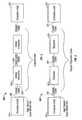
- FIG. 1is a system schematic of one embodiment of a seismic data acquisition system according to the present invention.
- the system 100includes a primary control and recording unit 102 for delivering commands to and receiving data signals from other units in the system 100.
- the primary control and recording unit or central recording system (“CRS") 102is a mobile unit ("truck").
- the primary control and recording unitmay be housed in any vehicle or carrier, or may be permanently or semi-permanently installed at a predetermined location.
- the primary control and recording unit 102is coupled to an intermediate data control unit known as a crossline unit (“XLU") 104.
- the XLU 104is coupled to a plurality of data acquisition units (“DAUs") 106, also referred to herein as "field boxes”.
- DAUsdata acquisition units
- the couplings 114a and 114b between XLUs 104provide redundant transmission paths as will be further described later.
- redundant transmission paths 110a and 110b between each DAU group and XLUsto ensure continuous data transmission even when a primary transmission fails or is otherwise not viable.
- One or more sensors 108are coupled to each DAU 106.
- the sensors 108are preferably micromachined micro-electromechanical system accelerometers referred to as MEMS accelerometers.
- each accelerometer package 108includes a three-component MEMS accelerometer sensor having three orthogonal axes of sensitivity.
- the sensorsmay alternatively be any conventional sensor for sensing acoustic energy waves.
- a sensor 108detects a seismic event such as an acoustic wave and converts the acoustic energy into a signal.
- the signalis received by an associated DAU 106, which digitizes the signal and transmits the digital result to the XLU.
- Signal packetsare created using electronic circuitry preferably housed in the DAU.
- the XLUreceives digitized results (packets) from the plurality of DAU's 106 and combines the several results for transmission to the CRS 102.
- Each packetcomprises digitized signals including one or more bits representing the sensed seismic signal and one or more bits "characterizing bits" for identifying the transmitted signal.
- Each characterizing bitincludes information relating to one or more of sensor location, time of transmission, sensor identification, trace number and record identification.
- the sensors 108are micromachined accelerometers integrally packaged with a converter thereby providing a digital output to its associated DAU 106, or directly to an XLU 104.
- couplings 112 between the truck and XLU, and between the XLU and DAUsare cables including one or more power/data conductors 112a and a synchronizing conductor 112b used for system timing.
- the couplings 112may be any suitable coupling capable of transferring electrical power and data signals. It is not necessary that one coupling 112a be the same coupling type as the other coupling 112b. Exemplary couplings may be any combination of wire, radio frequency, optical fiber, or electromagnetic.
- couplings 112a and 112bmight comprise a first signal (synchronizing signal) riding on a second power and/or data signal transmitted along a single transmission path or conductor.
- Figures 2-4show a particularly useful embodiment of the present invention wherein, the XLUs 104 are adapted to sense the coupling type used and are further adapted to accept wire conductors, fiber optic conductors or a combination of both to allow for adapting the system 100 to different length requirements.
- connection between XLUs 104can be either 100Mb Ethernet protocol or Gigabit Ethernet protocol. Copper cable may be used to transmit 100Mbit Ethernet protocol and optical fiber may be used to transmit either protocol. Additionally, connection a synchronization signal is transmitted separate from the Ethernet signals for copper wire but may be wavelength division multiplexed to share a fiber with Ethernet.
- optical fiberCompared to copper cable optical fiber has many desirable features compared to copper however it also has some drawbacks. Specifically the features are low loss allowing long transmission distances, and lightweight easing manual transportation, deployment and pickup of the cables by the user.
- the drawbacks of optical fiber in this environmentare associated with the use of optical connectors.
- Optical connectors which are required at the cable ends in a conventional systemare sensitive to contamination by dust, sand, and other foreign materials often encountered in the seismic field environment.
- the embodiment shown in Figs. 2-4retains the benefits of using optical fiber while eliminating the use of problematic optical connector used in the conventional system.
- the XLU 104is connected by a wire connector 200 to a cable 204.
- the cable 204includes a short cable section 206, typically less than 1 meter, for connecting the XLU 104 to a media converter 202 integrally disposed within the cable 204.
- the short cable section 206preferably comprises copper wire for coupling the XLU 104 to the media converter 202, although any suitable wire conductor is considered within the scope of this invention.
- electrical signalsare converted to optical signals and vice versa using well-known circuitry. There are no external connectors on the media converter 202 as it is an integral part of the cable 204.
- Optical fiberis then used for a major span 208 of the cable 204.
- the major fiber optic span 208supports nominal distances of up to 4 km with commonly commercially available fiber. Greater distances may be achieved using specially designed optic fibers.
- the media convertereliminates optical connectors in the cable 204.
- the fiber cable 208supports either 100 Mbit Ethernet or Gigabit Ethernet. Additionally, synchronization signal transmission and reception is supported in the fiber cable through the media converter. These signals may be transmitted on a single fiber using wavelengths divisions multiplexing techniques.
- Figure 3is a schematic showing a coupling arrangement for the several units of Figure 1 adapted for shorter system lengths.
- the cable 300comprises wire conductors 302 and repeater modules 304.
- Each repeater module 304is a bi-directional device adapted to receive a data package and retransmit the data package after conditioning the package signal.
- the repeater modules 304are integrally disposed within the cable 300 to eliminate the need for external connectors.
- Standard 100 Mbit Ethernetwill support only cable lengths up to 100 meters with commercially available cable.
- the repeater cable shown in Figure 3achieves the 400-meter distance by the integration of the repeater modules 304 molded within the cable. These active repeater modules 304 regenerate the signal in both directions and can achieve a transmission distance of 133 meters between repeaters and up to 400 meters overall.
- the copper repeater cable shownsupports a 100 Mbit Ethernet and a synchronization signal.
- FIG 4is a diagram of a crossline unit according to the present invention that allows for the connection of either coupling arrangement shown in Figures 2 and 3 .
- Connection to the XLU 104is made using one or more ports 400. These ports 400 are collectively referred to as a High Speed Dual Media Port. This port 400 accepts either of the cable configurations 204 or 300 described above and shown in Figures 2 and 3 .
- Circuits (not separately shown) within the XLU 104detects whether a cable is copper repeater cable 300 or copper/fiber cable 202 and responds accordingly. The detection circuit may be of the type described in U.S. Provisional Application serial number 60/297,354 filed on June 11, 2001 which is assigned to the assignee of this invention.
- the XLU 104allows up to 3 simultaneous high speed connections to the unit of any combination of copper repeater cable and copper/fiber cable. In this fashion a network of XLU's, DAU's and sensors may be combined in any needed configuration without the need to specially design any single component.
- the apparatus of the present inventionmight be practiced in numerous embodiments enabled by this teaching.
- the identification and illustration of XLU's and DAU's as separate field unitsshould not be construed as a necessary limitation of this invention.
- the present inventionprovides an apparatus for recording seismic data utilizing a unique data package structure that alleviates the need for precise timing control for signal transmission. Therefore, any reference to XLU and/or DAU could be construed as functional designations within one or more housings or as physical designations in separate housings.
- the functions of a DAUcould, in part or in whole, be transferred to an XLU.
- the method of the present inventionmay be practiced using any of the embodiments described above and shown in Figures 1-4 .
- the methodincludes power management of the seismic data acquisition system 100, data packaging and rerouting.
- the primary building block of a method according to the present inventionis a novel paradigm to seismic recording systems for collecting several time samples of a single location into a bundle or packet.
- These packetsare large enough that the necessary information to identify and route the packet is not a significant factor to the number of bits that must be transmitted.
- 93% of the bits transmitted using the system of the present inventionare seismic data.
- These packetsare transmitted to the CRS for recording as they assembled, rather than awaiting a time slot as with conventional methods. Thus, no assignment of time slot or master order control across the system is needed. This offers several advantages. Each packet is transmitted from one field unit 104 to the next field unit 104 of the array.
- a new available packetis added to the string of packets that are being transmitted, whenever there is time to introduce a new packet. It is not necessary for there to be a repeated series of clock pulses to keep all units in synchronization, so packets are not transmitted simultaneously. Thus, if the clock from the CRS is lost during the acquisition process a unit can continue to acquire and transmit data on an internal clock without interfering with other units or disrupting overall timing.
- each field unit 104is assigned a trace number for a particular record and a record ID for the seismic event recorded. As each packet is assembled for transmission, it is given a sequence number that represents the time of the first sample in the packet. Because the packet may be lost or corrupted in transmission, the data for each packet is stored in memory of the DAU. This remote data storage provides a backup copy of the data in case there are problems with transmission.
- a Field Equipment Interface (FEI)(software not separately shown) disposed in the CRS establishes a table in the CRS.
- This tablecontains a matrix of all the packets that are expected for an acquisition. Additionally, the table contains information about the memory location that packets are to occupy when they arrive at the CRS.
- the trace number and sequence number contained in the packetare examined by the FEI.
- the packetis "checked off' in the table and the seismic data is written to the proper location in the CRS memory. In this manner, the order of packet arrival is not important to determining the corresponding location of the sensor that created the data. That information is part of the packet information.
- the sequence numberis evaluated by the FEI and is used to control the memory location of the data storage without affecting other parts or timing of the system.
- a Cyclic Redundancy Counter(software bits) is added to the end of each packet.
- the CRCis checked with the data to determine if there was an error in transmitting the packet.
- a commandis sent to the previous unit to send the packet again.
- the datais transmitted from unit to unit in this manner until it reaches a higher order element that connects line segments. If a packet is corrupted at this level, there is no adjacent unit to command retransmission. In this case, the data package block is simply dropped and not retransmitted.
- This methodsubstantially reduces unexpected errors and system failures caused by corrupted data.
- the matrixis examined for missing packets.
- the FEIsends a command to a specific remote unit to retransmit a specified packet based on its time sequence if a missing packet is detected. Whenever missing packets cannot be retransmitted successfully, the corresponding locations in memory are filled with error values. A summary of the missing packets is sent to a master control unit, which is used to determine if the record is acceptable.
- Rerouting and retransmission capability enabled by the system according to the present inventioncreates the possibility that packets from one seismic event or record will arrive at the CRS at the same time as the last packets from the previous event.
- Each record or eventis assigned a Record ID.
- This same Record IDis associated with a unique packet table in the FEI.
- the FEIkeeps the previous table open during the primary acquisition of the current table to allow for the late arrival of packets and retransmission requests.
- the users of the systemset the amount of time, but it is expected that at least three tables would be active, i.e. open, at any time.
- test results from positions that will be used in the futureare evaluated in addition to receiving seismic data from remote units.
- thisis called "look ahead testing”. This is very difficult with conventional data transmission methods to include this data with the seismic data, because it disrupts the order of the data that is used to determine the location.
- test resultsare assigned a different identifier in the packet type. The status packet can then be transmitted from unit to unit back to the CRS in the same way that data packets are transmitted. At the FEI the type is examined and the data and status packets are separated for different data processing.
- a third type of packetis the "Command" packet.
- This packetnormally travels from the Central Recording System to the ground units to control the behavior or parameters of the unit.
- the command packetsare mixed with the data and status packets and sent by the same network protocols as the other types of packets.
- the methodallows the field units and the CRS to quickly determine the type of packet that is presented and to either reject or act on the packet based on its type and routing information.
- seismic packetwill be used to mean either or all status, command or data packets.
- a feature of a seismic systemis that all remote digitizer units sample in unison to an accuracy of 0.25 microseconds or better across the complete system and that they hold that accuracy for length of the record. This accuracy is much less than the time to transmit a signal through wires across the distance of a seismic recording system. This is further complicated by the potential for time delays in switches and rerouting of packets.
- One of the major limitations of conventional systems using packet transmission and established communication standards like Ethernetis that timing information and control is lost.
- a timing synchronization signal and the seismic packetsare transmitted by separate dedicated wires or in a single fiber as discussed above. This allows the use of application-specific protocol and methodology to distribute the timing signals and at the same time well established methods and protocols to distribute information that can be put into packets.
- a class of devices known as managed switchesare used to determine the direction from which data are coming and where the data are to go.
- a managed switchmay be, and is preferably a software solution managed within a particular unit such as an XLU.
- a managed switchkeeps a list of which port is generating information. If that unit appears in the "to" part of the message the switch sends the data to that port. Secondly, the switch sends out network messages to establish the health of the network. If there are two ways for a packet to get to the same node or cross line unit, one of the links is deliberately disabled. The managed switches continue to poll the network on a periodic basis. If links or units fail, the network is readjusted and the messages are sent by a different route. In this manner, a link can fail and the seismic crew can continue to record while repairs are made.
- the timing controlis provided with a redundant path for reliability with automatic switching of the route enabled by the method of using the data network performance to switch the synchronization signal.
- Another networking embodiment of the present inventionis the automatic adding of units to the network.
- the XLUs and DAUsare constantly sending network messages looking for new units. When a new unit responds it is attached to the network and the user display in the CRS shows the unit to be available for use to collect seismic data.
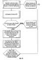
- Figures 5-7An exemplary data-handling method according to the present invention is shown in Figures 5-7 .
- Figure 5is a flow of system initiation commands
- Figure 6is a flow of data acquisition
- Figure 7is a flow of data packet routing.
- the methodis preferably conducted in part using a set of instructions stored on a readable medium such as magnetic disc or memory device in a unit such as the DAU described above and shown in Figures 1-4 .
- seismic data acquisitionis initiated as shown in Figure 5 .
- a userinitiates a request to record seismic data.
- the useris a field operator at the central truck recorder.
- the userselects which DAU field units are to be active for the record associated with the seismic data to be acquired. These selections are preferably performed by entering the selections into a computer console at the truck. Once the selections are entered, a command is sent via typical telemetry to the active DAU's 106.
- a field equipment interface unit housed in the CRS 102provides interface between the CRS and field equipment.
- a tableis created describing the active traces, and the table is transmitted to the field equipment interface.
- the field equipment interfaceexpands the table into a table of expected packets.
- the field equipment interfacethen prepares to receive packets from DAUs.
- the userselects a time to start recording using the truck console, and a command is issued to the DAUs to assign a time and record identification to packets as characterizing bits.
- a data acquisition methodbegins with sensors providing output signals indicative of a seismic event to activated field units.
- the DAU field unitsconvert the analog signals to digital signals and the digital signal is placed into a memory device within the field unit.
- the stored datais then transferred to a buffer memory as an output data packet.
- the data packetis then completed by adding characterizing bits, i.e. an identification header is attached which includes a record identification, a trace identification and a sequence number.
- the data packet with characterizing bitis then transmitted via the telemetry network.
- Figure 7is a flow to show a data packet routing method according to the present invention.
- Status packets and data packetsare combined on a networked seismic data acquisition system and the packets are routed through the network using Ethernet addresses. All packets are routed to the field equipment interface, and the field equipment interface is used to determine whether the arriving packet is a status packet or a data packet. Status packets are transmitted to an output display in the CRS for display to the user.
- an associated table for proper identificationis selected and a "received" bit flag is set in the table based on the trace identification and packet sequence information contained in the packet characterizing bits.
- the format of the seismic data in the packetis converted and removed from the packet in order and written to memory in time and trace order.
- the table of received packetsis examined for missing packets. If the table shows one or more missing packets, then commands are sent to DAUs to recover missing data from the DAU memory and retransmit the data package.
- the retransmitted data packageis treated in the same manner as the original data packages.
- the field equipment interfacedetermines that an arriving packet is a seismic data packet, then an associated table for proper identification is selected and a "received" bit flag is set in the table based on the trace identification and packet sequence information contained in the packet characterizing bits. Unrecoverable data package information is assigned a predetermined value to complete the records at the central recorder.
Landscapes
- Engineering & Computer Science (AREA)
- Remote Sensing (AREA)
- Physics & Mathematics (AREA)
- Life Sciences & Earth Sciences (AREA)
- Acoustics & Sound (AREA)
- Environmental & Geological Engineering (AREA)
- Geology (AREA)
- General Life Sciences & Earth Sciences (AREA)
- General Physics & Mathematics (AREA)
- Geophysics (AREA)
- Arrangements For Transmission Of Measured Signals (AREA)
- Geophysics And Detection Of Objects (AREA)
- Measurement Of Mechanical Vibrations Or Ultrasonic Waves (AREA)
Abstract
Description
- This invention relates generally to geologic surveys and more particularly to an apparatus and method for acquiring and processing seismic data.
- Conventional geophone and hydrophone systems used in seismic prospecting typically have several sensors that produce analog signals indicative of a seismic wave. The seismic wave is usually produced by an energy source such as a vibrator truck, explosives or by an air gun in the case of a hydrophone system. These seismic signals are then conducted to acquisition/conversion circuitry. The analog signals from one or more remote seismic sensors (hydrophones, geophones, or other seismic sensors) are sampled and converted to a series of digital values by the acquisition/conversion circuitry. The acquisition/conversion circuitry is typically configurable to, for example, adjust the sampling rate, alter any digital filtering or other digital signal processing parameters, or perform diagnostics.
- One or more of these acquisition/conversion circuits are connected to a data collection unit. Each data collection unit collects the series of digital values for all the seismic sensors connected to all the acquisition/conversion units connected to it. The data collection unit passes that data to a system controller, usually the truck, which includes a seismic recording device or Central Recording System ("CRS").
- A conventional system as described above is typically used in the seismic industry to enable a seismic data acquisition method called remote digitization. In this method a small number of analog signals are conveyed by wire to an analog to digital converter called a "field box" located remotely from the Central Recording System. In this field box analog signals acquired by the sensors are converted to digital form. Immediately after the conversion, digital data are transmitted to the CRS via serial communication. Typically, a processor and software are used to assign a time slot for transmitting the data. By example, the box closest to the CRS is assigned the first time slot and the next box the second time slot and so forth. A set of digital values from a field box associated with a particular time slot is called a trace. After all of the signals are digitized synchronously, each field box transmits the first trace at the first time. Then the second box would transmit the data for the first trace in the second time slot and so forth down the line. After all of the trace data for the first time slot are transmitted, i.e. time-one samples, then the process is repeated for another trace from all of the boxes i.e. time-two samples. In this manner, all of the data from the remote field units is transmitted to the CRS.
- Early in the development of remote digitization systems the data were immediately written to tape with all of time-one samples from all of the traces followed by time-two samples of all the traces. This method is called multiplexed. In larger systems, the CRS typically uses the known structure of the data to collect all of the time samples for one location or trace in sequential memory or tape location. This organization is called demultiplexed and is needed by the processing systems that will receive the seismic data.
- The conventional system has several limitations, especially as the number of traces in the recording system increase or redundant methods are needed to improve the reliability of the system. The order that data arrives at the CRS is used to imply or calculate the location of the field box sending the data to the CRS. Using arrival timing in this fashion means that the data cannot be sent via a route other than the predetermined initial route. If traces are contaminated during, transmission they must continue to be passed through the system to preserve the location so that the CRS can keep track of location. This contaminated data causes unexpected errors and failures of the system. The system must add some bits to the data that is transmitted to control the transmission. Because each data value is sent by itself, immediately upon acquisition, the overhead becomes very large and limits the amount of seismic data that can be transmitted over a single channel.
- Another drawback of the conventional system is the time required to recover from corrupted or otherwise unusable data packages transmitted from the data collection units to the main controller recorder.
- Another drawback of the conventional system is that a system designer typically must decide to use fiber optic cable or wire conductor cable to interconnect components regardless of system length requirements. The typical system component having fiber optic connectors is prone to failure caused by environmental conditions and is costly to use for shorter system lengths. Although copper wire is cost effective at shorter distances, a wire cable has a limited frequency response over longer distances and is much more cumbersome to deploy and retrieve.
US 5 627 798 ,WO 01/51956 US 5 623 455 each disclose a seismic data acquisition system comprising a plurality of sensors.- The present invention addresses the above-identified problems found in the conventional seismic data acquisition system by providing a system having distributed control over the several units comprising the system. Additionally, the present invention provides an apparatus and method for packaging and transmitting data efficiently and with more reliability.
- One aspect of the present invention provides a seismic data acquisition apparatus as claimed in
claim 1. - Another aspect of the present invention provides a seismic data acquisition system as claimed in claim 13.
- Another aspect of the present invention is a method of seismic data acquisition as claimed in claim 15.
- The novel features of this invention, as well as the invention itself, will be best understood from the attached drawings, taken along with the following description, in which similar reference characters refer to similar parts, and in which:
Figure 1 is a system schematic of one embodiment of a seismic data acquisition system according to the present invention;Figure 2 is a schematic showing a coupling arrangement for the several units ofFigure 1 suited for longer system lengths;Figure 3 is a schematic showing a coupling arrangement for the several units ofFigure 1 adapted for shorter system lengths;Figure 4 is a diagram of a crossline unit according to the present invention that allows for the connection of either coupling arrangement shown inFigures 2 and 3 ;Figure 5 is a flow chart showing a method of system initialization according to the present invention;Figure 6 is a flow chart showing a method of data acquisition and conditioning according to the present invention; andFigures 7A and7B are a flow chart showing a method of data routing and transmission according to the present invention.Figure 1 is a system schematic of one embodiment of a seismic data acquisition system according to the present invention. Thesystem 100 includes a primary control andrecording unit 102 for delivering commands to and receiving data signals from other units in thesystem 100. As shown, the primary control and recording unit or central recording system ("CRS")102 is a mobile unit ("truck"). Alternatively, the primary control and recording unit may be housed in any vehicle or carrier, or may be permanently or semi-permanently installed at a predetermined location.- The primary control and
recording unit 102 is coupled to an intermediate data control unit known as a crossline unit ("XLU")104. TheXLU 104 is coupled to a plurality of data acquisition units ("DAUs")106, also referred to herein as "field boxes". As shown, thecouplings XLUs 104 provide redundant transmission paths as will be further described later. Also shown areredundant transmission paths more sensors 108 are coupled to eachDAU 106. Thesensors 108 are preferably micromachined micro-electromechanical system accelerometers referred to as MEMS accelerometers. In a preferred embodiment, eachaccelerometer package 108 includes a three-component MEMS accelerometer sensor having three orthogonal axes of sensitivity. The sensors, however, may alternatively be any conventional sensor for sensing acoustic energy waves. - A
sensor 108 detects a seismic event such as an acoustic wave and converts the acoustic energy into a signal. The signal is received by an associatedDAU 106, which digitizes the signal and transmits the digital result to the XLU. Signal packets are created using electronic circuitry preferably housed in the DAU. - The XLU receives digitized results (packets) from the plurality of DAU's 106 and combines the several results for transmission to the
CRS 102. Each packet comprises digitized signals including one or more bits representing the sensed seismic signal and one or more bits "characterizing bits" for identifying the transmitted signal. Each characterizing bit includes information relating to one or more of sensor location, time of transmission, sensor identification, trace number and record identification. - In one embodiment, the
sensors 108 are micromachined accelerometers integrally packaged with a converter thereby providing a digital output to its associatedDAU 106, or directly to anXLU 104. - In one embodiment,
couplings 112 between the truck and XLU, and between the XLU and DAUs are cables including one or more power/data conductors 112a and a synchronizingconductor 112b used for system timing. Thecouplings 112 may be any suitable coupling capable of transferring electrical power and data signals. It is not necessary that onecoupling 112a be the same coupling type as theother coupling 112b. Exemplary couplings may be any combination of wire, radio frequency, optical fiber, or electromagnetic. Furthermore,couplings Figures 2-4 show a particularly useful embodiment of the present invention wherein, theXLUs 104 are adapted to sense the coupling type used and are further adapted to accept wire conductors, fiber optic conductors or a combination of both to allow for adapting thesystem 100 to different length requirements.- The connection between
XLUs 104 can be either 100Mb Ethernet protocol or Gigabit Ethernet protocol. Copper cable may be used to transmit 100Mbit Ethernet protocol and optical fiber may be used to transmit either protocol. Additionally, connection a synchronization signal is transmitted separate from the Ethernet signals for copper wire but may be wavelength division multiplexed to share a fiber with Ethernet. - Compared to copper cable optical fiber has many desirable features compared to copper however it also has some drawbacks. Specifically the features are low loss allowing long transmission distances, and lightweight easing manual transportation, deployment and pickup of the cables by the user. The drawbacks of optical fiber in this environment are associated with the use of optical connectors. Optical connectors which are required at the cable ends in a conventional system are sensitive to contamination by dust, sand, and other foreign materials often encountered in the seismic field environment. The embodiment shown in
Figs. 2-4 retains the benefits of using optical fiber while eliminating the use of problematic optical connector used in the conventional system. - Referring to
Figure 2 . TheXLU 104 is connected by awire connector 200 to acable 204. Thecable 204 includes ashort cable section 206, typically less than 1 meter, for connecting theXLU 104 to amedia converter 202 integrally disposed within thecable 204. Theshort cable section 206 preferably comprises copper wire for coupling theXLU 104 to themedia converter 202, although any suitable wire conductor is considered within the scope of this invention. Within themedia converter 202 electrical signals are converted to optical signals and vice versa using well-known circuitry. There are no external connectors on themedia converter 202 as it is an integral part of thecable 204. Optical fiber is then used for amajor span 208 of thecable 204. The majorfiber optic span 208 supports nominal distances of up to 4 km with commonly commercially available fiber. Greater distances may be achieved using specially designed optic fibers. The media converter eliminates optical connectors in thecable 204. Thefiber cable 208 supports either 100 Mbit Ethernet or Gigabit Ethernet. Additionally, synchronization signal transmission and reception is supported in the fiber cable through the media converter. These signals may be transmitted on a single fiber using wavelengths divisions multiplexing techniques. Figure 3 is a schematic showing a coupling arrangement for the several units ofFigure 1 adapted for shorter system lengths. For shorter cable distances, e.g. up to 400 meters, it is desirable to have a cable comprising only wire conductors, because the advantages of fiber diminish for shorter cables where weight and loss are not as important in view of the high cost of fiber cables. Shown are twoXLUs 104 coupled using acable 300 according to the present invention. Thecable 300 compriseswire conductors 302 andrepeater modules 304. Eachrepeater module 304 is a bi-directional device adapted to receive a data package and retransmit the data package after conditioning the package signal. In a preferred embodiment, therepeater modules 304 are integrally disposed within thecable 300 to eliminate the need for external connectors.Standard 100 Mbit Ethernet will support only cable lengths up to 100 meters with commercially available cable. Thus, the repeater cable shown inFigure 3 achieves the 400-meter distance by the integration of therepeater modules 304 molded within the cable. Theseactive repeater modules 304 regenerate the signal in both directions and can achieve a transmission distance of 133 meters between repeaters and up to 400 meters overall. The copper repeater cable shown supports a 100 Mbit Ethernet and a synchronization signal.Figure 4 is a diagram of a crossline unit according to the present invention that allows for the connection of either coupling arrangement shown inFigures 2 and 3 . Connection to theXLU 104 is made using one ormore ports 400. Theseports 400 are collectively referred to as a High Speed Dual Media Port. Thisport 400 accepts either of thecable configurations Figures 2 and 3 . Circuits (not separately shown) within theXLU 104 detects whether a cable iscopper repeater cable 300 or copper/fiber cable 202 and responds accordingly. The detection circuit may be of the type described inU.S. Provisional Application serial number 60/297,354 filed on June 11, 2001 XLU 104 allows up to 3 simultaneous high speed connections to the unit of any combination of copper repeater cable and copper/fiber cable. In this fashion a network of XLU's, DAU's and sensors may be combined in any needed configuration without the need to specially design any single component.- Those skilled in the art would recognize with the benefit of this disclosure that the apparatus of the present invention might be practiced in numerous embodiments enabled by this teaching. Thus, the identification and illustration of XLU's and DAU's as separate field units should not be construed as a necessary limitation of this invention. At a conceptual level, the present invention provides an apparatus for recording seismic data utilizing a unique data package structure that alleviates the need for precise timing control for signal transmission. Therefore, any reference to XLU and/or DAU could be construed as functional designations within one or more housings or as physical designations in separate housings. Moreover, the functions of a DAU could, in part or in whole, be transferred to an XLU.
- The method of the present invention may be practiced using any of the embodiments described above and shown in
Figures 1-4 . The method includes power management of the seismicdata acquisition system 100, data packaging and rerouting. - The primary building block of a method according to the present invention is a novel paradigm to seismic recording systems for collecting several time samples of a single location into a bundle or packet. These packets are large enough that the necessary information to identify and route the packet is not a significant factor to the number of bits that must be transmitted. By example, 93% of the bits transmitted using the system of the present invention are seismic data. These packets are transmitted to the CRS for recording as they assembled, rather than awaiting a time slot as with conventional methods. Thus, no assignment of time slot or master order control across the system is needed. This offers several advantages. Each packet is transmitted from one
field unit 104 to thenext field unit 104 of the array. At each location, a new available packet is added to the string of packets that are being transmitted, whenever there is time to introduce a new packet. It is not necessary for there to be a repeated series of clock pulses to keep all units in synchronization, so packets are not transmitted simultaneously. Thus, if the clock from the CRS is lost during the acquisition process a unit can continue to acquire and transmit data on an internal clock without interfering with other units or disrupting overall timing. - This packet approach is not used in conventional systems, because using a conventional system typically results in unacceptable loss of several time samples from a single location. A system according to the present invention increases reliability over the conventional system by the combined use of several techniques.
- Before data collection process begins, each
field unit 104 is assigned a trace number for a particular record and a record ID for the seismic event recorded. As each packet is assembled for transmission, it is given a sequence number that represents the time of the first sample in the packet. Because the packet may be lost or corrupted in transmission, the data for each packet is stored in memory of the DAU. This remote data storage provides a backup copy of the data in case there are problems with transmission. - At substantially the same time that the message is sent to the field units to assign trace number and record ID, a Field Equipment Interface (FEI) (software not separately shown) disposed in the CRS establishes a table in the CRS. This table contains a matrix of all the packets that are expected for an acquisition. Additionally, the table contains information about the memory location that packets are to occupy when they arrive at the CRS. As each packet arrives, the trace number and sequence number contained in the packet are examined by the FEI. The packet is "checked off' in the table and the seismic data is written to the proper location in the CRS memory. In this manner, the order of packet arrival is not important to determining the corresponding location of the sensor that created the data. That information is part of the packet information. In the same manner, it is possible for the last time sequence of data to arrive before the first sequence packet. The sequence number is evaluated by the FEI and is used to control the memory location of the data storage without affecting other parts or timing of the system.
- A Cyclic Redundancy Counter (software bits) is added to the end of each packet. As the packet is passed from unit to unit of the field equipment the CRC is checked with the data to determine if there was an error in transmitting the packet. For the exchange between two units, if there is an error in the transmission a command is sent to the previous unit to send the packet again. The data is transmitted from unit to unit in this manner until it reaches a higher order element that connects line segments. If a packet is corrupted at this level, there is no adjacent unit to command retransmission. In this case, the data package block is simply dropped and not retransmitted. Thus, all packets that are being handled and passed on by the system are uncorrupted packets. This method substantially reduces unexpected errors and system failures caused by corrupted data.
- As the FEI checks off the arrival of data packets, the matrix is examined for missing packets. The FEI sends a command to a specific remote unit to retransmit a specified packet based on its time sequence if a missing packet is detected. Whenever missing packets cannot be retransmitted successfully, the corresponding locations in memory are filled with error values. A summary of the missing packets is sent to a master control unit, which is used to determine if the record is acceptable.
- Rerouting and retransmission capability enabled by the system according to the present invention creates the possibility that packets from one seismic event or record will arrive at the CRS at the same time as the last packets from the previous event. Each record or event is assigned a Record ID. This same Record ID is associated with a unique packet table in the FEI. The FEI keeps the previous table open during the primary acquisition of the current table to allow for the late arrival of packets and retransmission requests. The users of the system set the amount of time, but it is expected that at least three tables would be active, i.e. open, at any time.
- In another embodiment of the present invention, test results from positions that will be used in the future are evaluated in addition to receiving seismic data from remote units. In seismic terms, this is called "look ahead testing". This is very difficult with conventional data transmission methods to include this data with the seismic data, because it disrupts the order of the data that is used to determine the location. In the present method, test results are assigned a different identifier in the packet type. The status packet can then be transmitted from unit to unit back to the CRS in the same way that data packets are transmitted. At the FEI the type is examined and the data and status packets are separated for different data processing.
- One of the challenges of this method for status messaging is to tell the source of the message. To address this issue a unique Status ID is assigned to each unit as it is powered up. Any status message then contains this Status ID to identify the source of a status response. A further extension to the status message is possible now that data and status can be mixed in the same data stream. This is the idea of an "unsolicited" status or an "emergency" message. There are several conditions in the system that require immediate attention. By example the power available from a battery could have dropped to a level so low that failure will happen in the next few minutes. In a large system the operator may not ask for a battery status often enough to measure this condition. The remote unit is programmed to send an "unsolicited" status to indicate this error to the CRS. Again the packet of status is coded so that the FEI recognizes this packet as unsolicited status and not as a routine response to a query, and thus treat it as needing immediate attention.
- In another method according to the present invention, a third type of packet is the "Command" packet. This packet normally travels from the Central Recording System to the ground units to control the behavior or parameters of the unit. There are also unit-to-unit command packets that are sent autonomously by the field units. These packets contain routing information so that they can be sent to some units or all units. The command packets are mixed with the data and status packets and sent by the same network protocols as the other types of packets. The method allows the field units and the CRS to quickly determine the type of packet that is presented and to either reject or act on the packet based on its type and routing information.
- Once the concept of packet organization for sending seismic data has been established then broader concepts from network theory can be applied to practical problems and limitations in the transmission of seismic data and status messages. For brevity, the term "seismic packet" will be used to mean either or all status, command or data packets.
- A feature of a seismic system is that all remote digitizer units sample in unison to an accuracy of 0.25 microseconds or better across the complete system and that they hold that accuracy for length of the record. This accuracy is much less than the time to transmit a signal through wires across the distance of a seismic recording system. This is further complicated by the potential for time delays in switches and rerouting of packets. One of the major limitations of conventional systems using packet transmission and established communication standards like Ethernet is that timing information and control is lost.
- In one method according to the present invention, a timing synchronization signal and the seismic packets are transmitted by separate dedicated wires or in a single fiber as discussed above. This allows the use of application-specific protocol and methodology to distribute the timing signals and at the same time well established methods and protocols to distribute information that can be put into packets.
- Using an XLU described above and shown in
Figure 4 according to the present invention, it is possible to plug any of the connectors into the unit in any order. One connector would be for cable toward the CRS and one away. The third connector would be used to make a redundant connection to a third node or cross line unit. It is very easy with this third connection to make networks that are very complex with many routes between two nodes. Therefore it is possible that any packet whether it is data or command could arrive at the same location from two different directions and at slightly different times. Network theory is used to control data management. A class of devices known as managed switches are used to determine the direction from which data are coming and where the data are to go. A managed switch may be, and is preferably a software solution managed within a particular unit such as an XLU. This is covered under the general class of Ethernet messaging protocol that is used by the system. A managed switch keeps a list of which port is generating information. If that unit appears in the "to" part of the message the switch sends the data to that port. Secondly, the switch sends out network messages to establish the health of the network. If there are two ways for a packet to get to the same node or cross line unit, one of the links is deliberately disabled. The managed switches continue to poll the network on a periodic basis. If links or units fail, the network is readjusted and the messages are sent by a different route. In this manner, a link can fail and the seismic crew can continue to record while repairs are made. - For a seismic system, it is not enough to reroute the seismic packets as the managed switch does. It is likely that a link has failed because the cable between the ground units has failed. For a seismic system, this also means that the all important synchronization signal is lost. The units can continue for a short time on internal clocks, but the master clocks are needed for long-term synchronization of the system. It is necessary then that the switches not only redirect the seismic data, but also establish new timing control paths. There is also the need to update the time adjustment for the different route, because the length and number of nodes will be different and cause different delays. In this invention, the information from the health message of the standard protocol is used to make the decisions on switching the timing control path. By this method, the timing control is provided with a redundant path for reliability with automatic switching of the route enabled by the method of using the data network performance to switch the synchronization signal.
- Another networking embodiment of the present invention is the automatic adding of units to the network. The XLUs and DAUs are constantly sending network messages looking for new units. When a new unit responds it is attached to the network and the user display in the CRS shows the unit to be available for use to collect seismic data.
- An exemplary data-handling method according to the present invention is shown in
Figures 5-7 .Figure 5 is a flow of system initiation commands,Figure 6 is a flow of data acquisition andFigure 7 is a flow of data packet routing. The method is preferably conducted in part using a set of instructions stored on a readable medium such as magnetic disc or memory device in a unit such as the DAU described above and shown inFigures 1-4 . - According to one embodiment of a method according to the present invention, seismic data acquisition is initiated as shown in
Figure 5 . A user initiates a request to record seismic data. Typically the user is a field operator at the central truck recorder. The user selects which DAU field units are to be active for the record associated with the seismic data to be acquired. These selections are preferably performed by entering the selections into a computer console at the truck. Once the selections are entered, a command is sent via typical telemetry to the active DAU's106. A field equipment interface unit housed in theCRS 102 provides interface between the CRS and field equipment. - A table is created describing the active traces, and the table is transmitted to the field equipment interface. The field equipment interface expands the table into a table of expected packets. The field equipment interface then prepares to receive packets from DAUs.
- The user selects a time to start recording using the truck console, and a command is issued to the DAUs to assign a time and record identification to packets as characterizing bits.
- Referring now to
Figure 6 , a data acquisition method according to the present invention begins with sensors providing output signals indicative of a seismic event to activated field units. The DAU field units convert the analog signals to digital signals and the digital signal is placed into a memory device within the field unit. - The stored data is then transferred to a buffer memory as an output data packet. The data packet is then completed by adding characterizing bits, i.e. an identification header is attached which includes a record identification, a trace identification and a sequence number. The data packet with characterizing bit is then transmitted via the telemetry network.
Figure 7 is a flow to show a data packet routing method according to the present invention. Status packets and data packets are combined on a networked seismic data acquisition system and the packets are routed through the network using Ethernet addresses. All packets are routed to the field equipment interface, and the field equipment interface is used to determine whether the arriving packet is a status packet or a data packet. Status packets are transmitted to an output display in the CRS for display to the user.- When the field equipment interface determines that an arriving packet is a seismic data packet, then an associated table for proper identification is selected and a "received" bit flag is set in the table based on the trace identification and packet sequence information contained in the packet characterizing bits. The format of the seismic data in the packet is converted and removed from the packet in order and written to memory in time and trace order.
- After a predetermined time elapses, the table of received packets is examined for missing packets. If the table shows one or more missing packets, then commands are sent to DAUs to recover missing data from the DAU memory and retransmit the data package.
- The retransmitted data package is treated in the same manner as the original data packages. The field equipment interface determines that an arriving packet is a seismic data packet, then an associated table for proper identification is selected and a "received" bit flag is set in the table based on the trace identification and packet sequence information contained in the packet characterizing bits. Unrecoverable data package information is assigned a predetermined value to complete the records at the central recorder.
- The foregoing description is directed to particular embodiments of the present invention for the purpose of illustration and explanation. It will be apparent, however, to one skilled in the art that many modifications and changes to the embodiment set forth above are possible without departing from the scope of the invention, as defined by the following claims.
Claims (28)
- A seismic data acquisition apparatus (100) comprising:a) a plurality of sensors (108) for detecting a seismic event, each sensor (108) having an output indicative of the seismic event; andb) at least one unit (104) coupled to the plurality of sensors (108) for receiving each sensor output, the unit (104) adapted to combine the received outputs into individual data packets, wherein to each data packet one or more characterizing bits are added representing the time of only the first time sample within the transmitted data packet, and the unit (104) further being adapted to transmit said data packets.
- The apparatus of claim 1, wherein the one or more characterizing bits include information relating to at least one of sensor location, timing, sensor identification, trace number and record identification.
- The apparatus of claim 1, wherein each of the plurality of sensors (108) is selected from a group consisting of i) accelerometers; ii) geophones; and iii) hydrophones.
- The apparatus of claim 1, wherein each of the sensors (108) includes a MEMS accelerometer.
- The apparatus of claim 4, wherein each of the sensors (108) further comprises a three-component MEMS accelerometer package.
- The apparatus of claim 1, further comprising at least one second unit (104) coupled to the first unit (104) for receiving the data packets over a primary route, wherein said at least one second unit includes a switching device for determining a direction from which the data packets are transmitted.
- The apparatus of claim 6, wherein the switching device is adapted to select a secondary route for receiving said data packets when said primary route is not available.
- The apparatus of claim 6, wherein the at least one second unit includes at least one first port for coupling a low speed route to the second unit and at least one second input port for coupling a high speed route to the second unit.
- The apparatus of claim 6, wherein the primary route includes at least one of i) an optic fiber and ii) a wire conductor.
- The apparatus of claim 7, wherein the primary route is an optic fiber and the secondary route is a wire conductor.
- The apparatus of claim 7, wherein the primary route is a wire conductor and the secondary route is an optic fiber.
- The apparatus of claim 1, further comprising a central controller (102) for receiving the data packets, said central controller adapted to determine from said characterizing bits a timing parameter for storing said received data packets in order.
- A seismic data acquisition system comprising the apparatus of any preceding claim, further comprising a main control and recording unit (102) coupled to the field unit (104) for receiving the data packets.
- The system of claim 13, further comprising a conductor coupling the field unit (104) to the main control and recording unit (102) for transmitting a synchronizing signal between the field unit and the central control and recording unit.
- A method of seismic data acquisition, comprising: a) sensing acoustic energy with a plurality of sensors (108), each sensor providing an output indicative of the sensed energy; b) receiving the outputs from the plurality of sensors (108) by a unit (104); c) combining in said unit (104) the sensor outputs into data packets; d) adding in said unit (104) to the data packets one or more characterizing bits representing the time of only the first time sample within the transmitted data packet; and e) transmitting the data packets.
- The method of claim 15, wherein the one or more characterizing bits include information relating to at least one of sensor location, timing, sensor identification, trace number and record identification.
- The method of claim 15, further comprising wavelength division multiplexing the data packet.
- The method of claim 15, wherein the data packet includes a synchronizing signal and an Ethernet protocol.
- The method of claim 15, wherein each of the plurality of sensors (108) is selected from a group consisting of i) accelerometers ; ii) geophones; and iii) hydrophones.
- The method of claim 15, wherein each of the sensors (108) includes a MEMS accelerometer.
- The method of claim 20, wherein each of the sensors (108) further comprises a three-component MEMS accelerometer package.
- The method of claim 15, further comprising: a) receiving the data packets at a unit having a plurality of input ports, said data packets being transmitted over a primary route; b) determining a direction from which the data packets are transmitted using a switching device.
- The method of claim 22 further comprising selecting a secondary route for receiving said data packets when said primary route is not available.
- The method of claim 22, wherein the unit includes at least one first port for coupling a low speed route to the unit and at least one second input port for coupling a high speed route to the unit.
- The method of claim 22, wherein the primary route includes at least one of i) an optic fiber and ii) a wire conductor.
- The method of claim 23, wherein the primary route is an optic fiber and the secondary route is a wire conductor.
- The method of claim 23, wherein the primary route is a wire conductor and the secondary route is an optic fiber.
- The method of claim 15, further comprising: a) receiving the data packets at a central controller ; and b) determining from said characterizing bits a timing parameter for storing said received data packets in order at the central controller.
Applications Claiming Priority (3)
| Application Number | Priority Date | Filing Date | Title |
|---|---|---|---|
| US31808601P | 2001-09-07 | 2001-09-07 | |
| US318086P | 2001-09-07 | ||
| PCT/US2002/028699WO2003023448A2 (en) | 2001-09-07 | 2002-09-09 | Seismic data acquisition apparatus and method |
Publications (3)
| Publication Number | Publication Date |
|---|---|
| EP1435008A2 EP1435008A2 (en) | 2004-07-07 |
| EP1435008A4 EP1435008A4 (en) | 2007-05-09 |
| EP1435008B1true EP1435008B1 (en) | 2011-11-09 |
Family
ID=23236584
Family Applications (1)
| Application Number | Title | Priority Date | Filing Date |
|---|---|---|---|
| EP02773319AExpired - LifetimeEP1435008B1 (en) | 2001-09-07 | 2002-09-09 | Seismic data acquisition apparatus and method |
Country Status (7)
| Country | Link |
|---|---|
| US (2) | US20030128627A1 (en) |
| EP (1) | EP1435008B1 (en) |
| AT (1) | ATE533073T1 (en) |
| AU (1) | AU2002336470A1 (en) |
| CA (1) | CA2459897C (en) |
| NO (1) | NO20041518L (en) |
| WO (1) | WO2003023448A2 (en) |
Cited By (1)
| Publication number | Priority date | Publication date | Assignee | Title |
|---|---|---|---|---|
| CN106249275A (en)* | 2015-06-04 | 2016-12-21 | 中国石油化工股份有限公司 | Earthquake-capturing automatic routing system and method |
Families Citing this family (36)
| Publication number | Priority date | Publication date | Assignee | Title |
|---|---|---|---|---|
| US6594284B1 (en)* | 1998-09-16 | 2003-07-15 | Cirrus Logic, Inc. | Network synchronization |
| US6667967B1 (en) | 1999-05-14 | 2003-12-23 | Omninet Capital, Llc | High-speed network of independently linked nodes |
| US8045565B1 (en)* | 2001-11-20 | 2011-10-25 | Brookline Flolmstead Llc | Method and apparatus for an environmentally hardened ethernet network system |
| AU2003278901B2 (en)* | 2002-09-23 | 2009-12-03 | Ion Geophysical Corporation | Seafloor seismic recording using MEMS |
| US20050047275A1 (en)* | 2003-09-01 | 2005-03-03 | Geo-X Systems, Ltd. | Synchronization and positioning of seismic data acquisition systems |
| US7269095B2 (en)* | 2002-10-04 | 2007-09-11 | Aram Systems, Ltd. | Synchronization of seismic data acquisition systems |
| GB2395640B (en)* | 2002-11-22 | 2006-06-07 | Westerngeco Seismic Holdings | Implementing a network infrastructure in a seismic acquisition system |
| US7561493B2 (en)* | 2003-05-30 | 2009-07-14 | Fairfield Industries, Inc. | Method and apparatus for land based seismic data acquisition |
| US8228759B2 (en) | 2003-11-21 | 2012-07-24 | Fairfield Industries Incorporated | System for transmission of seismic data |
| US7124028B2 (en) | 2003-11-21 | 2006-10-17 | Fairfield Industries, Inc. | Method and system for transmission of seismic data |
| US8170802B2 (en)* | 2006-03-21 | 2012-05-01 | Westerngeco L.L.C. | Communication between sensor units and a recorder |
| CA2654887A1 (en)* | 2006-06-09 | 2007-12-21 | Ion Geophysical Corporation | Operating state management for seismic data acquisition |
| CN101512532B (en)* | 2006-06-10 | 2012-02-15 | 爱诺华有限公司 | Apparatus and method for integrating survey parameters into a header |
| US7894301B2 (en)* | 2006-09-29 | 2011-02-22 | INOVA, Ltd. | Seismic data acquisition using time-division multiplexing |
| US8077740B2 (en)* | 2007-02-01 | 2011-12-13 | INOVA, Ltd. | Apparatus and method for reducing noise in seismic data |
| US8136383B2 (en)* | 2007-08-28 | 2012-03-20 | Westerngeco L.L.C. | Calibrating an accelerometer |
| EP2034336A1 (en)* | 2007-09-07 | 2009-03-11 | Vibration Technology Limited | Data transmission system |
| US8964500B2 (en)* | 2007-10-05 | 2015-02-24 | Honeywell International Inc. | Communication in a seismic sensor array |
| US8019549B2 (en)* | 2008-12-10 | 2011-09-13 | Honeywell International Inc. | Event-based power management for seismic sensors |
| US7974151B2 (en)* | 2008-09-17 | 2011-07-05 | Westerngeco L.L.C. | Cetacean protection system |
| US8254207B2 (en)* | 2008-09-22 | 2012-08-28 | Geza Nemeth | System and method for seismic data acquisition |
| EP2356489A1 (en) | 2008-11-10 | 2011-08-17 | Conocophillps Company | Practical autonomous seismic recorder implementation and use |
| US9304220B2 (en)* | 2008-12-23 | 2016-04-05 | Westerngeco L.L.C. | Handling equipment failure in a subterranean survey data acquisition network |
| US8382383B2 (en)* | 2009-06-23 | 2013-02-26 | Pgs Geophysical As | Structure for optical connector ferrule and method for making |
| US8483010B2 (en)* | 2010-01-27 | 2013-07-09 | Westerngeco L.L.C. | Providing communications redundancy using one or more loop connections in a subterranean survey system |
| US9010170B2 (en) | 2010-08-16 | 2015-04-21 | Westerngeco L.L.C. | Method and apparatus to test an accelerometer |
| US8639474B2 (en)* | 2010-08-31 | 2014-01-28 | Toshiba International Corporation | Microcontroller-based diagnostic module |
| US9217805B2 (en) | 2010-10-01 | 2015-12-22 | Westerngeco L.L.C. | Monitoring the quality of particle motion data during a seismic acquisition |
| CN102628957B (en)* | 2011-06-22 | 2014-05-07 | 中国科学院地质与地球物理研究所 | Computer network-based novel digital seismograph with mega-channel level |
| EP2541786A1 (en)* | 2011-06-29 | 2013-01-02 | Tyco Electronics Belgium EC BVBA | Data transmission cable with integrated repeater unit and cable assembly comprising such a cable |
| CN103226206B (en)* | 2012-01-25 | 2018-11-27 | 英洛瓦(天津)物探装备有限责任公司 | Multi-pair power distribution |
| US20140200816A1 (en)* | 2013-01-14 | 2014-07-17 | Westerngeco L.L.C. | Seismic data processing |
| CN103499833B (en)* | 2013-09-27 | 2016-08-17 | 中国石油集团东方地球物理勘探有限责任公司 | A kind of wired seismic instrument of built-in power and data transmission method |
| EP2887100B1 (en)* | 2013-12-20 | 2022-10-26 | Sercel | Method for downloading data to a central unit in a seismic data acquisition system |
| WO2015099564A1 (en)* | 2013-12-25 | 2015-07-02 | Schlumberger, Holdings Limited | A borehole seismic tool and method of seismic surveying |
| CN112612054B (en)* | 2021-01-06 | 2024-08-02 | 中油奥博(成都)科技有限公司 | Submarine seismic data acquisition system and acquisition method based on distributed optical fiber sensing |
Family Cites Families (19)
| Publication number | Priority date | Publication date | Assignee | Title |
|---|---|---|---|---|
| US4408307A (en)* | 1978-12-26 | 1983-10-04 | Texas Instruments Incorporated | Optical transmission of digital seismic data |
| CA1170756A (en)* | 1980-11-17 | 1984-07-10 | Donald W. Harvey | Remote seismic data system |
| FR2574190B1 (en)* | 1984-11-30 | 1987-05-15 | Inst Francais Du Petrole | METHOD FOR CONTROLLING THE STORAGE OF DATA RECEIVED BY A SEISMIC RECORDING SYSTEM AND DEVICE FOR IMPLEMENTING SAME |
| US4932004A (en)* | 1986-02-21 | 1990-06-05 | Honeywell Inc. | Fiber optic seismic system |
| US5627798A (en)* | 1995-05-05 | 1997-05-06 | I/O Exploration Products (U.S.A.), Inc. | Hierarchical telemetry system for seismic acquisition |
| US5623455A (en)* | 1995-05-25 | 1997-04-22 | Western Atlas International, Inc. | Apparatus and method for acquiring seismic data |
| US5659195A (en)* | 1995-06-08 | 1997-08-19 | The Regents Of The University Of California | CMOS integrated microsensor with a precision measurement circuit |
| US5745392A (en) | 1995-10-05 | 1998-04-28 | Chevron U.S.A. Inc. | Method for reducing data storage and transmission requirements for seismic data |
| US6292108B1 (en) | 1997-09-04 | 2001-09-18 | The Board Of Trustees Of The Leland Standford Junior University | Modular, wireless damage monitoring system for structures |
| US6011753A (en) | 1998-03-19 | 2000-01-04 | Syntron, Inc. | Control and monitoring of devices external to a marine seismic streamer |
| US6115325A (en)* | 1998-04-20 | 2000-09-05 | Syntron, Inc. | Variable length data field in a seismic data stream |
| US6411866B1 (en)* | 1998-11-18 | 2002-06-25 | David P Cavanagh | Digital transmission and control system for vehicles |
| US6188645B1 (en)* | 1999-06-11 | 2001-02-13 | Geosensor Corporation | Seismic sensor array with electrical-to optical transformers |
| FR2799004B1 (en) | 1999-09-27 | 2001-10-19 | Inst Francais Du Petrole | TRANSMISSION METHOD AND SYSTEM USING A STANDARD TRANSMISSION NETWORK, TO CONNECT ELEMENTS OF A SEISMIC DEVICE |
| GB0000919D0 (en)* | 2000-01-14 | 2000-03-08 | Geco As | Seismic data acquisition |
| US6377184B1 (en)* | 2000-04-11 | 2002-04-23 | Gary A. Minker | Transmission line safety monitoring system |
| US6714761B1 (en)* | 2000-11-21 | 2004-03-30 | Starcom Wireless, Inc. | Meteor burst communication system having the capability of simultaneous communication with multiple remote units |
| CA2450456C (en)* | 2001-06-11 | 2011-09-20 | Input/Output, Inc. | Apparatus and method for distributed control of seismic data acquisition |
| US6701788B2 (en)* | 2001-07-31 | 2004-03-09 | Kelsey-Hayes Company | Multiple output inertial sensing device |
- 2002
- 2002-09-09EPEP02773319Apatent/EP1435008B1/ennot_activeExpired - Lifetime
- 2002-09-09AUAU2002336470Apatent/AU2002336470A1/ennot_activeAbandoned
- 2002-09-09CACA2459897Apatent/CA2459897C/ennot_activeExpired - Lifetime
- 2002-09-09ATAT02773319Tpatent/ATE533073T1/enactive
- 2002-09-09USUS10/237,469patent/US20030128627A1/ennot_activeAbandoned
- 2002-09-09WOPCT/US2002/028699patent/WO2003023448A2/ennot_activeApplication Discontinuation
- 2004
- 2004-04-06NONO20041518Apatent/NO20041518L/ennot_activeApplication Discontinuation
- 2004-10-18USUS10/967,728patent/US7012853B2/ennot_activeExpired - Lifetime
Cited By (2)
| Publication number | Priority date | Publication date | Assignee | Title |
|---|---|---|---|---|
| CN106249275A (en)* | 2015-06-04 | 2016-12-21 | 中国石油化工股份有限公司 | Earthquake-capturing automatic routing system and method |
| CN106249275B (en)* | 2015-06-04 | 2018-08-31 | 中国石油化工股份有限公司 | Earthquake-capturing automatic routing system and method |
Also Published As
| Publication number | Publication date |
|---|---|
| AU2002336470A1 (en) | 2003-03-24 |
| US20030128627A1 (en) | 2003-07-10 |
| CA2459897A1 (en) | 2003-03-20 |
| WO2003023448A3 (en) | 2003-12-04 |
| WO2003023448A2 (en) | 2003-03-20 |
| US7012853B2 (en) | 2006-03-14 |
| ATE533073T1 (en) | 2011-11-15 |
| CA2459897C (en) | 2013-10-29 |
| EP1435008A2 (en) | 2004-07-07 |
| NO20041518L (en) | 2004-04-06 |
| US20050083784A1 (en) | 2005-04-21 |
| EP1435008A4 (en) | 2007-05-09 |
Similar Documents
| Publication | Publication Date | Title |
|---|---|---|
| EP1435008B1 (en) | Seismic data acquisition apparatus and method | |
| US5627798A (en) | Hierarchical telemetry system for seismic acquisition | |
| US7142129B2 (en) | Method and system for downhole clock synchronization | |
| CA2004109C (en) | Multiple transmission path seismic telemetering system | |
| CA2802247C (en) | Seismic survey communication systems and methods | |
| US4398271A (en) | Device for data transmission between seismic data acquisition devices and a recording device | |
| JP2599355B2 (en) | Data transmission equipment | |
| EP1405106B1 (en) | Apparatus and method for distributed control of seismic data acquisition | |
| EP0870176B1 (en) | A system and a method for measuring a continuous signal | |
| EP1995609B1 (en) | Seismic data acquisition | |
| JP3545437B2 (en) | Packet switching test method and apparatus | |
| US20140204704A1 (en) | Systems and methods for improving bandwidth of wireless networks | |
| US7551816B1 (en) | Arrangement for low cost path protection for optical communications networks | |
| KR100583921B1 (en) | Data Acquisition System and Method for Loading Large Aircraft | |
| US6115325A (en) | Variable length data field in a seismic data stream | |
| CN104237935B (en) | Common data recording system architecture for geophysical exploration and constructing method of architecture | |
| CN103226206B (en) | Multi-pair power distribution | |
| CN103226208B (en) | It is synchronous by the clock of optical fiber | |
| US11105941B2 (en) | Managing movement of data packets along a geophysical sensor cable | |
| US20160168983A1 (en) | Scalable Borehole Acquisition System | |
| CN111081294A (en) | A system and method for multi-channel synchronous acquisition and centralized storage of acoustic signals | |
| JP2006080775A (en) | Data transmission system | |
| Wirth | Fiber Optic Extension of Apple LocalTalk Networks | |
| CN103226207A (en) | Analog in power supply module | |
| Collins | Serial digital multiplexing of transducer data for intrinsically safe applications |
Legal Events
| Date | Code | Title | Description |
|---|---|---|---|
| PUAI | Public reference made under article 153(3) epc to a published international application that has entered the european phase | Free format text:ORIGINAL CODE: 0009012 | |
| 17P | Request for examination filed | Effective date:20040402 | |
| AK | Designated contracting states | Kind code of ref document:A2 Designated state(s):AT BE BG CH CY CZ DE DK EE ES FI FR GB GR IE IT LI LU MC NL PT SE SK TR | |
| AX | Request for extension of the european patent | Extension state:AL LT LV MK RO SI | |
| RAP1 | Party data changed (applicant data changed or rights of an application transferred) | Owner name:INPUT/OUTPUT, INC. | |
| A4 | Supplementary search report drawn up and despatched | Effective date:20070413 | |
| RAP1 | Party data changed (applicant data changed or rights of an application transferred) | Owner name:ION GEOPHYSICAL CORPORATION | |
| 17Q | First examination report despatched | Effective date:20090525 | |
| RAP1 | Party data changed (applicant data changed or rights of an application transferred) | Owner name:INOVA LTD. | |
| GRAP | Despatch of communication of intention to grant a patent | Free format text:ORIGINAL CODE: EPIDOSNIGR1 | |
| GRAS | Grant fee paid | Free format text:ORIGINAL CODE: EPIDOSNIGR3 | |
| GRAA | (expected) grant | Free format text:ORIGINAL CODE: 0009210 | |
| AK | Designated contracting states | Kind code of ref document:B1 Designated state(s):AT BE BG CH CY CZ DE DK EE ES FI FR GB GR IE IT LI LU MC NL PT SE SK TR | |
| REG | Reference to a national code | Ref country code:GB Ref legal event code:FG4D | |
| REG | Reference to a national code | Ref country code:CH Ref legal event code:EP | |
| REG | Reference to a national code | Ref country code:IE Ref legal event code:FG4D | |
| REG | Reference to a national code | Ref country code:NL Ref legal event code:T3 | |
| REG | Reference to a national code | Ref country code:DE Ref legal event code:R096 Ref document number:60241521 Country of ref document:DE Effective date:20120202 | |
| PG25 | Lapsed in a contracting state [announced via postgrant information from national office to epo] | Ref country code:PT Free format text:LAPSE BECAUSE OF FAILURE TO SUBMIT A TRANSLATION OF THE DESCRIPTION OR TO PAY THE FEE WITHIN THE PRESCRIBED TIME-LIMIT Effective date:20120309 Ref country code:BE Free format text:LAPSE BECAUSE OF FAILURE TO SUBMIT A TRANSLATION OF THE DESCRIPTION OR TO PAY THE FEE WITHIN THE PRESCRIBED TIME-LIMIT Effective date:20111109 Ref country code:GR Free format text:LAPSE BECAUSE OF FAILURE TO SUBMIT A TRANSLATION OF THE DESCRIPTION OR TO PAY THE FEE WITHIN THE PRESCRIBED TIME-LIMIT Effective date:20120210 Ref country code:SE Free format text:LAPSE BECAUSE OF FAILURE TO SUBMIT A TRANSLATION OF THE DESCRIPTION OR TO PAY THE FEE WITHIN THE PRESCRIBED TIME-LIMIT Effective date:20111109 | |
| PG25 | Lapsed in a contracting state [announced via postgrant information from national office to epo] | Ref country code:CY Free format text:LAPSE BECAUSE OF FAILURE TO SUBMIT A TRANSLATION OF THE DESCRIPTION OR TO PAY THE FEE WITHIN THE PRESCRIBED TIME-LIMIT Effective date:20111109 | |
| PG25 | Lapsed in a contracting state [announced via postgrant information from national office to epo] | Ref country code:CZ Free format text:LAPSE BECAUSE OF FAILURE TO SUBMIT A TRANSLATION OF THE DESCRIPTION OR TO PAY THE FEE WITHIN THE PRESCRIBED TIME-LIMIT Effective date:20111109 Ref country code:EE Free format text:LAPSE BECAUSE OF FAILURE TO SUBMIT A TRANSLATION OF THE DESCRIPTION OR TO PAY THE FEE WITHIN THE PRESCRIBED TIME-LIMIT Effective date:20111109 Ref country code:DK Free format text:LAPSE BECAUSE OF FAILURE TO SUBMIT A TRANSLATION OF THE DESCRIPTION OR TO PAY THE FEE WITHIN THE PRESCRIBED TIME-LIMIT Effective date:20111109 Ref country code:SK Free format text:LAPSE BECAUSE OF FAILURE TO SUBMIT A TRANSLATION OF THE DESCRIPTION OR TO PAY THE FEE WITHIN THE PRESCRIBED TIME-LIMIT Effective date:20111109 Ref country code:BG Free format text:LAPSE BECAUSE OF FAILURE TO SUBMIT A TRANSLATION OF THE DESCRIPTION OR TO PAY THE FEE WITHIN THE PRESCRIBED TIME-LIMIT Effective date:20120209 | |
| PG25 | Lapsed in a contracting state [announced via postgrant information from national office to epo] | Ref country code:IT Free format text:LAPSE BECAUSE OF FAILURE TO SUBMIT A TRANSLATION OF THE DESCRIPTION OR TO PAY THE FEE WITHIN THE PRESCRIBED TIME-LIMIT Effective date:20111109 | |
| PLBE | No opposition filed within time limit | Free format text:ORIGINAL CODE: 0009261 | |
| STAA | Information on the status of an ep patent application or granted ep patent | Free format text:STATUS: NO OPPOSITION FILED WITHIN TIME LIMIT | |
| REG | Reference to a national code | Ref country code:AT Ref legal event code:MK05 Ref document number:533073 Country of ref document:AT Kind code of ref document:T Effective date:20111109 | |
| 26N | No opposition filed | Effective date:20120810 | |
| REG | Reference to a national code | Ref country code:DE Ref legal event code:R097 Ref document number:60241521 Country of ref document:DE Effective date:20120810 | |
| PG25 | Lapsed in a contracting state [announced via postgrant information from national office to epo] | Ref country code:AT Free format text:LAPSE BECAUSE OF FAILURE TO SUBMIT A TRANSLATION OF THE DESCRIPTION OR TO PAY THE FEE WITHIN THE PRESCRIBED TIME-LIMIT Effective date:20111109 | |
| PG25 | Lapsed in a contracting state [announced via postgrant information from national office to epo] | Ref country code:MC Free format text:LAPSE BECAUSE OF NON-PAYMENT OF DUE FEES Effective date:20120930 Ref country code:ES Free format text:LAPSE BECAUSE OF FAILURE TO SUBMIT A TRANSLATION OF THE DESCRIPTION OR TO PAY THE FEE WITHIN THE PRESCRIBED TIME-LIMIT Effective date:20120220 | |
| REG | Reference to a national code | Ref country code:CH Ref legal event code:PL | |
| REG | Reference to a national code | Ref country code:IE Ref legal event code:MM4A | |
| PG25 | Lapsed in a contracting state [announced via postgrant information from national office to epo] | Ref country code:FI Free format text:LAPSE BECAUSE OF FAILURE TO SUBMIT A TRANSLATION OF THE DESCRIPTION OR TO PAY THE FEE WITHIN THE PRESCRIBED TIME-LIMIT Effective date:20111109 | |
| PG25 | Lapsed in a contracting state [announced via postgrant information from national office to epo] | Ref country code:IE Free format text:LAPSE BECAUSE OF NON-PAYMENT OF DUE FEES Effective date:20120909 Ref country code:LI Free format text:LAPSE BECAUSE OF NON-PAYMENT OF DUE FEES Effective date:20120930 Ref country code:DE Free format text:LAPSE BECAUSE OF NON-PAYMENT OF DUE FEES Effective date:20130403 Ref country code:CH Free format text:LAPSE BECAUSE OF NON-PAYMENT OF DUE FEES Effective date:20120930 | |
| REG | Reference to a national code | Ref country code:DE Ref legal event code:R119 Ref document number:60241521 Country of ref document:DE Effective date:20130403 | |
| PGFP | Annual fee paid to national office [announced via postgrant information from national office to epo] | Ref country code:NL Payment date:20130910 Year of fee payment:12 | |
| PG25 | Lapsed in a contracting state [announced via postgrant information from national office to epo] | Ref country code:TR Free format text:LAPSE BECAUSE OF FAILURE TO SUBMIT A TRANSLATION OF THE DESCRIPTION OR TO PAY THE FEE WITHIN THE PRESCRIBED TIME-LIMIT Effective date:20111109 | |
| PG25 | Lapsed in a contracting state [announced via postgrant information from national office to epo] | Ref country code:LU Free format text:LAPSE BECAUSE OF NON-PAYMENT OF DUE FEES Effective date:20120909 | |
| PG25 | Lapsed in a contracting state [announced via postgrant information from national office to epo] | Ref country code:NL Free format text:LAPSE BECAUSE OF NON-PAYMENT OF DUE FEES Effective date:20150401 | |
| PGFP | Annual fee paid to national office [announced via postgrant information from national office to epo] | Ref country code:GB Payment date:20150909 Year of fee payment:14 | |
| REG | Reference to a national code | Ref country code:FR Ref legal event code:PLFP Year of fee payment:15 | |
| GBPC | Gb: european patent ceased through non-payment of renewal fee | Effective date:20160909 | |
| PG25 | Lapsed in a contracting state [announced via postgrant information from national office to epo] | Ref country code:GB Free format text:LAPSE BECAUSE OF NON-PAYMENT OF DUE FEES Effective date:20160909 | |
| REG | Reference to a national code | Ref country code:FR Ref legal event code:PLFP Year of fee payment:16 | |
| REG | Reference to a national code | Ref country code:FR Ref legal event code:PLFP Year of fee payment:17 | |
| PGFP | Annual fee paid to national office [announced via postgrant information from national office to epo] | Ref country code:FR Payment date:20210812 Year of fee payment:20 |