EP1434941B1 - Fuel injection valve - Google Patents
Fuel injection valveDownload PDFInfo
- Publication number
- EP1434941B1 EP1434941B1EP02800535AEP02800535AEP1434941B1EP 1434941 B1EP1434941 B1EP 1434941B1EP 02800535 AEP02800535 AEP 02800535AEP 02800535 AEP02800535 AEP 02800535AEP 1434941 B1EP1434941 B1EP 1434941B1
- Authority
- EP
- European Patent Office
- Prior art keywords
- valve
- fuel injection
- groove
- injection valve
- fuel
- Prior art date
- Legal status (The legal status is an assumption and is not a legal conclusion. Google has not performed a legal analysis and makes no representation as to the accuracy of the status listed.)
- Expired - Lifetime
Links
- 239000000446fuelSubstances0.000titleclaimsabstractdescription69
- 238000002347injectionMethods0.000titleclaimsabstractdescription47
- 239000007924injectionSubstances0.000titleclaimsabstractdescription47
- 238000002485combustion reactionMethods0.000claimsabstractdescription25
- 238000007789sealingMethods0.000claimsabstractdescription5
- 238000005530etchingMethods0.000claimsdescription3
- 239000007921spraySubstances0.000description15
- 238000004939cokingMethods0.000description6
- 238000004519manufacturing processMethods0.000description6
- 239000000203mixtureSubstances0.000description3
- 239000000126substanceSubstances0.000description3
- 238000010276constructionMethods0.000description2
- 230000007257malfunctionEffects0.000description2
- 238000003860storageMethods0.000description2
- 238000004891communicationMethods0.000description1
- 230000006835compressionEffects0.000description1
- 238000007906compressionMethods0.000description1
- 238000013016dampingMethods0.000description1
- 230000007423decreaseEffects0.000description1
- 230000001419dependent effectEffects0.000description1
- 238000013461designMethods0.000description1
- 238000011161developmentMethods0.000description1
- 230000018109developmental processEffects0.000description1
- 238000009826distributionMethods0.000description1
- 230000002996emotional effectEffects0.000description1
- 238000005516engineering processMethods0.000description1
- 230000005284excitationEffects0.000description1
- 238000003197gene knockdownMethods0.000description1
- 238000000034methodMethods0.000description1
- 239000002244precipitateSubstances0.000description1
- 230000001376precipitating effectEffects0.000description1
- 238000012545processingMethods0.000description1
Images

Classifications
- F—MECHANICAL ENGINEERING; LIGHTING; HEATING; WEAPONS; BLASTING
- F02—COMBUSTION ENGINES; HOT-GAS OR COMBUSTION-PRODUCT ENGINE PLANTS
- F02M—SUPPLYING COMBUSTION ENGINES IN GENERAL WITH COMBUSTIBLE MIXTURES OR CONSTITUENTS THEREOF
- F02M61/00—Fuel-injectors not provided for in groups F02M39/00 - F02M57/00 or F02M67/00
- F02M61/16—Details not provided for in, or of interest apart from, the apparatus of groups F02M61/02 - F02M61/14
- F02M61/18—Injection nozzles, e.g. having valve seats; Details of valve member seated ends, not otherwise provided for
- F02M61/1806—Injection nozzles, e.g. having valve seats; Details of valve member seated ends, not otherwise provided for characterised by the arrangement of discharge orifices, e.g. orientation or size
- F—MECHANICAL ENGINEERING; LIGHTING; HEATING; WEAPONS; BLASTING
- F02—COMBUSTION ENGINES; HOT-GAS OR COMBUSTION-PRODUCT ENGINE PLANTS
- F02M—SUPPLYING COMBUSTION ENGINES IN GENERAL WITH COMBUSTIBLE MIXTURES OR CONSTITUENTS THEREOF
- F02M51/00—Fuel-injection apparatus characterised by being operated electrically
- F02M51/06—Injectors peculiar thereto with means directly operating the valve needle
- F02M51/061—Injectors peculiar thereto with means directly operating the valve needle using electromagnetic operating means
- F02M51/0625—Injectors peculiar thereto with means directly operating the valve needle using electromagnetic operating means characterised by arrangement of mobile armatures
- F02M51/0664—Injectors peculiar thereto with means directly operating the valve needle using electromagnetic operating means characterised by arrangement of mobile armatures having a cylindrically or partly cylindrically shaped armature, e.g. entering the winding; having a plate-shaped or undulated armature entering the winding
- F02M51/0685—Injectors peculiar thereto with means directly operating the valve needle using electromagnetic operating means characterised by arrangement of mobile armatures having a cylindrically or partly cylindrically shaped armature, e.g. entering the winding; having a plate-shaped or undulated armature entering the winding the armature and the valve being allowed to move relatively to each other or not being attached to each other
- F—MECHANICAL ENGINEERING; LIGHTING; HEATING; WEAPONS; BLASTING
- F02—COMBUSTION ENGINES; HOT-GAS OR COMBUSTION-PRODUCT ENGINE PLANTS
- F02M—SUPPLYING COMBUSTION ENGINES IN GENERAL WITH COMBUSTIBLE MIXTURES OR CONSTITUENTS THEREOF
- F02M61/00—Fuel-injectors not provided for in groups F02M39/00 - F02M57/00 or F02M67/00
- F02M61/16—Details not provided for in, or of interest apart from, the apparatus of groups F02M61/02 - F02M61/14
- F02M61/162—Means to impart a whirling motion to fuel upstream or near discharging orifices
- F—MECHANICAL ENGINEERING; LIGHTING; HEATING; WEAPONS; BLASTING
- F02—COMBUSTION ENGINES; HOT-GAS OR COMBUSTION-PRODUCT ENGINE PLANTS
- F02M—SUPPLYING COMBUSTION ENGINES IN GENERAL WITH COMBUSTIBLE MIXTURES OR CONSTITUENTS THEREOF
- F02M2200/00—Details of fuel-injection apparatus, not otherwise provided for
- F02M2200/30—Fuel-injection apparatus having mechanical parts, the movement of which is damped
- F02M2200/306—Fuel-injection apparatus having mechanical parts, the movement of which is damped using mechanical means
Definitions
- the inventionis based on a fuel injection valve according to the preamble of claim 1.
- a Fuel injectorincludes the fuel in one combustion chamber formed by a piston / cylinder construction injected, and with a protruding into the combustion chamber Spark plug is provided.
- the fuel injection valveis with at least one row over the circumference of the Fuel injector arranged distributed Spray openings provided. Through a targeted injection of fuel over the spray orifices becomes one beam-guided combustion process by forming a Mixture cloud realized with at least one jet.
- a disadvantage of the above-mentioned document known fuel injection valveis in particular the Coking of the ejection openings, which thereby clog and the flow through the fuel injector diminish impermissibly. This leads to malfunctions the internal combustion engine.
- DE 199 11 928 A1shows an injection valve for a Internal combustion engine.
- the fuel injectorhas a valve body, injection ports and a Fuel storage on the downstream side of a Pin section of the valve body.
- An opening on the Outside of the injection holehas a width, the is generally larger than a width thereof, with the Width of the injection opening decreases gradually inwards, so that the fuel in the direction of the width with a predetermined angle is injected.
- the vastness of Injection opening in the direction of injection of the fuel within the predetermined angle in the width directionis essentially uniform.
- Through holesare on the middle section or on the sides in the Width direction of the injection port formed. The Through holes are connected to the fuel storage is and has a width that is greater than the width the injection port.
- the fuel injection valve according to the invention with the Features of claim 1has In contrast, the advantage that at one of the combustion chamber of Internal combustion engine facing front side of Valve seat body of the fuel injection valve a groove-like surface structure is formed, which prevents fuel in the area of Abspritzö Maschinenen can knock down, causing a zu186 the ejection openings avoided by coking residues becomes.
- the number of groovesis arbitrary and of a single groove, which of a Any injection opening emanates, up to a number may increase, which is equal to the number of Spray openings is.
- the groove-like surface structure produced simultaneously with the valve seat body or be subsequently introduced into thisis advantageousously, the groove-like surface structure produced simultaneously with the valve seat body or be subsequently introduced into this.
- the groove-like Surface structurein a simple and cost-effective manner by mechanical processing, such as. B. turning, or by chemical treatment, such as. As etching, can be produced is.
- Fig. 1shows in an excerpted sectional view Embodiment of an inventive Fuel injection valve 1.
- the fuel injector 1is in the form of a Brennscherinspritzvent ils 1 for Fuel injection systems of mixture compression, spark-ignited internal combustion engines running.
- the Fuel injector 1is suitable for direct Injecting fuel into a not shown Combustion chamber of an internal combustion engine.
- the fuel injection valve 1consists of a Nozzle body 2, in which a valve needle 3 is arranged.
- the valve needle 3is for example via a weld 41 in operative connection with a valve closing body 4, the arranged with a valve seat body 5 on a Valve seat surface 6 cooperates to a sealing seat.
- Fuel injection valve 1is in Embodiment to an inwardly opening Fuel injection valve 1, which over several Abspritzö Anlagenen 7 has, at least one for Axis of the valve seat body 5 concentric circle are arranged.
- the nozzle body 2is by a seal 8 against a Outer pole 9 acting as an actuator for the valve needle 3 Magnetic coil 10 sealed.
- the magnetic coil 10is in one Coil housing 11 encapsulated and on a bobbin 12th wound, which at an inner pole 13 of the magnetic coil 10th is applied.
- the inner pole 13 and the outer pole 9are connected by a Split 26 separated from each other and rely on a Connecting component 29 from.
- the magnetic coil 10is connected via a Line 19 of a via an electrical plug contact 17th energized electric current.
- the plug contact 17is surrounded by a plastic sheath 18, the Inner pole 13 may be molded.
- the valve needle 3is in a valve needle guide fourteenth guided, which is designed disk-shaped. to Stroke adjustment is a paired shim 15.
- An the other side of the dial 15is a Anchor 20. This is about a first flange 21st non-positively connected to the valve needle 3 in conjunction, which by a weld 22 with the first flange 21 connected is.
- On the first flange 21is supported Return spring 23 from which in the present design of Fuel injection valve 1 by a sleeve 24 Bias is brought.
- a second flange 31stDownstream of the armature 20 is a second flange 31st arranged, which serves as a lower anchor stop. He is over a weld 33 frictionally with the valve needle. 3 connected. Between the armature 20 and the second flange 31 is an elastic intermediate ring 32 for damping Anchor bouncers when closing the fuel injector 1 arranged.
- the armature 20 and the Valve seat body 5extend fuel channels 30a to 30c.
- the fuelis supplied via a central fuel supply 16 supplied and filtered by a filter element 25.
- the Fuel injection valve 1is opposed by a seal 28 sealed a distribution line not shown.
- the fuel injection valve 1 on one facing the combustion chamber of the internal combustion engine End face 35 of the valve seat body. 5a groove-like Surface structure 34, which is different from the on at least one circuit arranged spray openings 7 extends radially outward.
- a groove-like Surface structure 34becomes fuel, which during of the injection process at the tip of the Fuel injection valve 1 precipitates, of the Abspritzö réelleen 7 transported away, so that the Coking tendency of the ejection openings 7 is reduced, whereby malfunctions of the fuel injection valve 1 by clogging the spray openings 7 and a Inadmissible reduction of fuel flow can be prevented.
- the measures according to the inventionare in Figs. 2A and 2B shown in more detail and in the Description explained.
- the armature 20drops sufficient reduction of the magnetic field by the pressure of the Return spring 23 on the first flange 21 from the inner pole thirteenth from, causing the valve needle 3 against the stroke direction emotional. As a result, the valve closing body 4 is placed on the Valve seat surface 6 and the fuel injection valve. 1 will be closed. The armature 20 sits on the through the second flange 31 formed anchor stop.
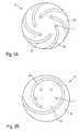
- Figs. 2A and 2Bshow in an enlarged schematic Top view of the discharge-side end of the in Fig. 1st illustrated fuel injection valve 1 two Embodiments of the inventive measures.
- valve 1has the fuel injection valve 1 in the region of Valve seat body 5 at a combustion chamber of the Internal combustion engine facing end face 35, the preferably curved conically or dome-shaped outward is, over a groove-like surface structure 34 which for removal from itself in the area of the ejection openings 7 serves precipitating fuel.
- the coking of the ejection openings 7can be reduced become. Since the diameter of the ejection openings 7 is typically about 100 microns, the risk that the Clogging holes 7 clog with coking over time and thus the flow rate impermissibly restricted becomes, relatively large. This is especially due to the high Temperatures when igniting the in the combustion chamber injected mixture cloud conditionally, as a result Components of the fuel at the top of the Deposit fuel injector 1.
- the groove-like surface structure 34may in Exit region of the ejection openings 7 remaining Fuel be removed, so that the Spray holes 7 not by coking residue can grow up.
- Fig. 2Ashows a first embodiment of groove-like surface structure 34.
- the number of Spray openings 7is present Embodiment six. You are on one to one Center axis of the fuel injection valve 1 and / or the Valve seat body 5 concentric circle arranged. From each of the ejection openings 7 assumes a groove 36, the a radially from the respective ejection opening 7 to the outside directed directional component has.
- the grooves 36are here more or less bent to an optimum Removal of fuel, located in the area of Spray holes 7 reflected down to ensure. Alternatively, it is possible to reduce the Manufacturing effort to reduce the number of grooves 36 so that, for example, only every second spray opening 7 with a groove 36 is in communication.
- the grooves 36may have any cross-section, wherein a U-shaped cross-section flow and production technology is the cheapest.
- the cross sectioncan For example, to the radially outer ends 38 of Flatten grooves 36; furthermore, the ends 38 can also be widened.
- the production of the grooves 36takes place for example, by turning during manufacture of the Valve seat body 5. Also a subsequent production on chemical way, for example by etching, is possible.
- Fig. 2Bshows in the same view as Fig. 2A, a second Embodiment of an inventively designed Valve seat body 5 of a fuel injection valve 1.
- the fuel injection valve 1six spray openings 7, which also on a Are arranged circle.
- a single groove 37which emanates from only one spray opening 7 and helical so extends radially outward that all Spray openings 7 radially within the single groove 37th lie.
- Spray openings 7 on a helical lineto arrange, which parallel to the helical Single groove 37 runs.
- the single groove 37must have the ejection openings 7 at least once completely circulated, so that the removal of fuel is guaranteed by all spray openings 7.
- the single groove 37 in the Production of the valve seat body 5 made by turning or subsequently by chemical or mechanical meansbe introduced.
- As a possible cross-sectional shapeoffers also a U-shaped cross-section possibly with widened and / or flattened end 38 at.
- the inventionis not limited to those shown Embodiments limited and for any Number of spray openings 7, which in any way at the discharge end of the fuel injection valve. 1 can be arranged for any number of grooves 36 and for any construction of Fuel injectors 1 applicable.
Landscapes
- Engineering & Computer Science (AREA)
- Chemical & Material Sciences (AREA)
- Combustion & Propulsion (AREA)
- Mechanical Engineering (AREA)
- General Engineering & Computer Science (AREA)
- Physics & Mathematics (AREA)
- Electromagnetism (AREA)
- Fuel-Injection Apparatus (AREA)
Abstract
Description
Translated fromGermanDie Erfindung geht aus von einem Brennstoffeinspritzventilnach der Gattung des Anspruchs 1.The invention is based on a fuel injection valveaccording to the preamble of
Aus der DE 198 04 463 A1 ist ein Brennstoffeinspritzsystemfür eine gemischverdichtende, fremdgezündeteBrennkraftmaschine bekannt, welches einBrennstoffeinspritzventil umfaßt, das Brennstoff in einenvon einer Kolben-/Zylinderkonstruktion gebildeten Brennraumeinspritzt, und mit einer in den Brennraum ragendenZündkerze versehen ist. Das Brennstoffeinspritzventil istmit mindestens einer Reihe über den Umfang desBrennstoffeinspritzventils verteilt angeordnetenAbspritzöffnungen versehen. Durch eine gezielte Einspritzungvon Brennstoff über die Abspritzöffnungen wird einestrahlgeführtes Brennverfahren durch Bildung einerGemischwolke mit mindestens einem Strahl realisiert.From DE 198 04 463 A1 is a fuel injection systemfor a mixture-compacting, spark-ignitedInternal combustion engine is known which aFuel injector includes the fuel in onecombustion chamber formed by a piston / cylinder constructioninjected, and with a protruding into the combustion chamberSpark plug is provided. The fuel injection valve iswith at least one row over the circumference of theFuel injector arranged distributedSpray openings provided. Through a targeted injectionof fuel over the spray orifices becomes onebeam-guided combustion process by forming aMixture cloud realized with at least one jet.
Nachteilig an dem aus der obengenannten Druckschriftbekannten Brennstoffeinspritzventil ist insbesondere dieVerkokung der Abspritzöffnungen, welche dadurch verstopfenund den Durchfluß durch das Brennstoffeinspritzventilunzulässig stark vermindern. Dies führt zu Fehlfunktionender Brennkraftmaschine.A disadvantage of the above-mentioned documentknown fuel injection valve is in particular theCoking of the ejection openings, which thereby clogand the flow through the fuel injectordiminish impermissibly. This leads to malfunctionsthe internal combustion engine.
DE 199 11 928 A1 zeigt ein Einspritzventil für eineBrennkraftmaschine. Das Brennstoffeinspritzventil hateinen Ventilkörper, Einspritzöffnungen und einenBrennstoffspeicher auf der stromabwärtigen Seite einesStiftabschnitts des Ventilkörpers. Eine Öffnung auf derAußenseite der Einspritzöfnung hat eine Breite, dieallgemein größer ist, als eine Weite davon, wobei dieBreite der Einspritzöffnung allmählich einwärts abnimmt,so daß der Brennstoff in der Richtung der Breite mit einemvorbestimmten Winkel eingespritzt wird. Die Weite derEinspritzöffnung in Einspritzrichtung des Brennstoffsinnerhalb des vorbestimmten Winkels in der Breitenrichtungist im wesentlichen gleichmäßig. Durchgangslöcher sind andem Mittelabschnitt bzw. an den Seiten in derBreitenrichtung der Einspritzöffnung ausgebildet. DieDurchgangslöcher sind mit dem Brennstoffspeicher verbundenist und haben eine Weite, die größer ist, als die Weiteder Einspritzöffnung.DE 199 11 928 A1 shows an injection valve for aInternal combustion engine. The fuel injector hasa valve body, injection ports and aFuel storage on the downstream side of aPin section of the valve body. An opening on theOutside of the injection hole has a width, theis generally larger than a width thereof, with theWidth of the injection opening decreases gradually inwards,so that the fuel in the direction of the width with apredetermined angle is injected. The vastness ofInjection opening in the direction of injection of the fuelwithin the predetermined angle in the width directionis essentially uniform. Through holes are onthe middle section or on the sides in theWidth direction of the injection port formed. TheThrough holes are connected to the fuel storageis and has a width that is greater than the widththe injection port.
Das erfindungsgemäße Brennstoffeinspritzventil mit denMerkmalen des Anspruchs 1 hatdemgegenüber den Vorteil, daß an einer dem Brennraum derBrennkraftmaschine zugewandten Stirnseite desVentilsitzkörpers des Brennstoffeinspritzventils einerillenartige Oberflächenstruktur ausgebildet ist, welcheverhindert, daß sich Brennstoff im Bereich derAbspritzöffnungen niederschlagen kann, wodurch ein Zuwachsender Abspritzöffnungen durch Verkokungsrückstände vermiedenwird.The fuel injection valve according to the invention with theFeatures of
Durch die in den Unteransprüchen aufgeführten Maßnahmen sindvorteilhafte Weiterbildungen des im Hauptanspruchangegebenen Brennstoffeinspritzventils möglich.By the measures listed in the dependent claims areadvantageous developments of the main claimspecified fuel injector possible.
Von Vorteil ist insbesondere, daß die Anzahl der Rillenbeliebig ist und von einer Einzelrille, welche von einerbeliebigen Abspritzöffnung ausgeht, bis zu einer Anzahlansteigen kann, welche gleich der Anzahl derAbspritzöffnungen ist.It is particularly advantageous that the number of groovesis arbitrary and of a single groove, which of aAny injection opening emanates, up to a numbermay increase, which is equal to the number ofSpray openings is.
Vorteilhafterweise kann die rillenartige Oberflächenstrukturgleichzeitig mit dem Ventilsitzkörper hergestellt odernachträglich in diesen eingebracht werden.Advantageously, the groove-like surface structureproduced simultaneously with the valve seat body orbe subsequently introduced into this.
Weiterhin ist von Vorteil, daß die rillenartigeOberflächenstruktur in einfacher und kostengünstiger Weisemittels mechanischer Bearbeitung, wie z. B. Drehen, odermittels chemischer Bearbeitung, wie z. B. Ätzen, herstellbarist.Furthermore, it is advantageous that the groove-likeSurface structure in a simple and cost-effective mannerby mechanical processing, such as. B. turning, orby chemical treatment, such as. As etching, can be producedis.
Ausführungsbeispiele der Erfindung sind in der Zeichnungvereinfacht dargestellt und in der nachfolgendenBeschreibung näher erläutert. Es zeigen:
- Fig. 1
- einen schematischen Schnitt durch ein erstesAusführungsbeispiel eines erfindungsgemäßenBrennstoffeinspritzventils in einer Gesamtansicht;
- Fig. 2A
- eine vergrößerte schematische Aufsicht auf einerstes Ausführungsbeispiel eines mit denerfindungsgemäßen Maßnahmen ausgestaltetenVentilsitzkörpers des in Fig. 1 dargestelltenBrennstoffeinspritzventils; und
- Fig. 2B
- eine vergrößerte schematische Aufsicht auf einzweites Ausführungsbeispiel eines mit denerfindungsgemäßen Maßnahmen ausgestaltetenVentilsitzkörpers des in Fig. 1 dargestelltenBrennstoffeinspritzventils.
- Fig. 1
- a schematic section through a first embodiment of a fuel injection valve according to the invention in an overall view;
- Fig. 2A
- an enlarged schematic plan view of a first embodiment of an embodiment of the invention designed valve seat body of the fuel injection valve shown in Figure 1. and
- Fig. 2B
- an enlarged schematic plan view of a second embodiment of a configured with the inventive measures valve seat body of the fuel injection valve shown in Fig. 1.
Fig. 1 zeigt in einer auszugsweisen Schnittdarstellung einAusführungsbeispiel eines erfindungsgemäßenBrennstoff einspritzventils 1. Das Brennstoffeinspritzventil1 ist in der Form eines Brennstoffeinspritzvent ils 1 fürBrennstoffeinspritzanlagen von gemischverdichtenden,fremdgezündeten Brennkraftmaschinen ausgeführt. DasBrennstoffeinspritzventil 1 eignet sich zum direktenEinspritzen von Brennstoff in einen nicht dargestelltenBrennraum einer Brennkraftmaschine.Fig. 1 shows in an excerpted sectional viewEmbodiment of an inventive
Das Brennstoffeinspritzventil 1 besteht aus einemDüsenkörper 2, in welchem eine Ventilnadel 3 angeordnet ist.Die ventilnadel 3 steht beispielsweise über eine Schweißnaht41 in Wirkverbindung mit einem Ventilschließkörper 4, dermit einer auf einem Ventilsitzkörper 5 angeordnetenVentilsitzfläche 6 zu einem Dichtsitz zusammenwirkt. Bei demBrennstoffeinspritzventil 1 handelt es sich imAusführungsbeispiel um ein nach innen öffnendesBrennstoffeinspritzventil 1, welches über mehrereAbspritzöffnungen 7 verfügt, die auf zumindest einem zur Achse des Ventilsitzkörpers 5 konzentrischen Kreisangeordnet sind.The
Der Düsenkörper 2 ist durch eine Dichtung 8 gegen einenAußenpol 9 einer als Aktor für die Ventilnadel 3 wirkendenMagnetspule 10 abgedichtet. Die Magnetspule 10 ist in einemSpulengehäuse 11 gekapselt und auf einen Spulenträger 12gewickelt, welcher an einem Innenpol 13 der Magnetspule 10anliegt. Der Innenpol 13 und der Außenpol 9 sind durch einenSpalt 26 voneinander getrennt und stützen sich auf einemVerbindungsbauteil 29 ab. Die Magnetspule 10 wird über eineLeitung 19 von einem über einen elektrischen Steckkontakt 17zuführbaren elektrischen Strom erregt. Der Steckkontakt 17ist von einer Kunststoffummantelung 18 umgeben, die amInnenpol 13 angespritzt sein kann.The
Die Ventilnadel 3 ist in einer Ventilnadelführung 14geführt, welche scheibenförmig ausgeführt ist. ZurHubeinstellung dient eine zugepaarte Einstellscheibe 15. Ander anderen Seite der Einstellscheibe 15 befindet sich einAnker 20. Dieser steht über einen ersten Flansch 21kraftschlüssig mit der Ventilnadel 3 in Verbindung, welchedurch eine Schweißnaht 22 mit dem ersten Flansch 21verbunden ist. Auf dem ersten Flansch 21 stützt sich eineRückstellfeder 23 ab, welche in der vorliegenden Bauform desBrennstoffeinspritzventils 1 durch eine Hülse 24 aufVorspannung gebracht wird.The valve needle 3 is in a valve needle guide fourteenthguided, which is designed disk-shaped. toStroke adjustment is a paired
Abströmseitig des Ankers 20 ist ein zweiter Flansch 31angeordnet, der als unterer Ankeranschlag dient. Er ist übereine Schweißnaht 33 kraftschlüssig mit der Ventilnadel 3verbunden. Zwischen dem Anker 20 und dem zweiten Flansch 31ist ein elastischer Zwischenring 32 zur Dämpfung vonAnkerprellern beim Schließen des Brennstoffeinspritzventils1 angeordnet.Downstream of the
In der Ventilnadelführung 14, im Anker 20 und amVentilsitzkörper 5 verlaufen Brennstoffkanäle 30a bis 30c.Der Brennstoff -wird über eine zentrale Brennstoffzufuhr 16 zugeführt und durch ein Filterelement 25 gefiltert. DasBrennstoffeinspritzventil 1 ist durch eine Dichtung 28 gegeneine nicht weiter dargestellte Verteilerleitung abgedichtet.In the
Erfindungsgemäß weist das Brennstoffeinspritzventil 1 aneiner dem Brennraum der Brennkraftmaschine zugewandtenStirnseite 35 des Ventilsitzkörpers. 5 eine rillenartigeOberflächenstruktur 34 auf, welche sich von den aufzumindest einem Kreis angeordneten Abspritzöffnungen 7radial nach außen erstreckt. Durch die rillenartigeOberflächenstruktur 34 wird Brennstoff, welcher sich währenddes Einspritzvorgangs an der Spitzes desBrennstoffeinspritzventils 1 niederschlägt, von denAbspritzöffnungen 7 wegtransportiert, so daß dieVerkokungsneigung der Abspritzöffnungen 7 vermindert wird,wodurch Fehlfunktionen des Brennstoffeinspritzventils 1durch Verstopfen der Abspritzöffnungen 7 und einerunzulässigen Verringerung des Brennstoffdurchflussesvorgebeugt werden kann. Die erfindungsgemäßen Maßnahmen sindin den Fig. 2A und 2B näher dargestellt und in derBeschreibung erläutert.According to the invention, the
Im Ruhezustand des Brennstoffeinspritzventils 1 wird dererste Flansch 21 an der Ventilnadel 3 von der Rückstellfeder23 entgegen einer Hubrichtung so beaufschlagt, daß derVentilschließkörper 4 am Ventilsitz 6 in dichtender Anlagegehalten wird. Der Anker 20 liegt auf dem Zwischenring 32auf, der sich auf dem zweiten Flansch 31 abstützt. BeiErregung der Magnetspule 10 baut diese ein Magnetfeld auf,welches den Anker 20 entgegen der Federkraft derRückstellfeder 23 in Hubrichtung bewegt. Dabei nimmt derAnker 20 den ersten Flansch 21, welcher mit der Ventilnadel3 verschweißt ist, und damit die Ventilnadel 3 ebenfalls inHubrichtung mit. Der mit der Ventilnadel 3 in Wirkverbindungstehende Ventilschließkörper 4 hebt von der Ventilsitzfläche6 ab, wodurch der Brennstoff an den Abspritzöffnungen 7abgespritzt wird.In the idle state of the
Wird der Spulenstrom abgeschaltet, fällt der Anker 20 nachgenügendem Abbau des Magnetfeldes durch den Druck derRückstellfeder 23 auf den ersten Flansch 21 vom Innenpol 13ab, wodurch sich die Ventilnadel 3 entgegen der Hubrichtungbewegt. Dadurch setzt der Ventilschließkörper 4 auf derVentilsitzfläche 6 auf und das Brennstoffeinspritzventil 1wird geschlossen. Der Anker 20 setzt auf dem durch denzweiten Flansch 31 gebildeten Ankeranschlag auf.If the coil current is turned off, the
Fig. 2A und 2B zeigen in einer vergrößerten schematischenAufsicht auf das abspritzseitige Ende des in Fig. 1dargestellten Brennstoffeinspritzventils 1 zweiAusführungsbeispiele der erfindungsgemäßen Maßnahmen.Figs. 2A and 2B show in an enlarged schematicTop view of the discharge-side end of the in Fig. 1stillustrated
Wie bereits in der Beschreibung zu Fig. 1 kurz angesprochen,verfügt das Brennstoffeinspritzventil 1 im Bereich desVentilsitzkörpers 5 an einer dem Brennraum derBrennkraftmaschine zugewandten Stirnseite 35, dievorzugsweise konisch oder kalottenförmig nach außen gewölbtist, über eine rillenartige Oberflächenstruktur 34, welchezum Abtransport von sich im Bereich der Abspritzöffnungen 7niederschlagenden Brennstoffs dient.As already briefly mentioned in the description of FIG. 1,has the
Durch die erfindungsgemäße rillenartige Oberflächenstruktur34 kann die Verkokung der Abspritzöffnungen 7 reduziertwerden. Da der Durchmesser der Abspritzöffnungen 7typischerweise ca. 100 µm beträgt, ist die Gefahr, daß dieAbspritzöffnungen 7 durch Verkokung mit der Zeit verstopfenund somit die Durchflußmenge unzulässig stark eingeschränktwird, relativ groß. Dies ist insbesondere durch die hohenTemperaturen beim Durchzünden der in den Brennraumeingespritzten Gemischwolke bedingt, da sich dadurchBestandteile des Brennstoffs an der Spitze desBrennstoffeinspritzventils 1 absetzen. Durch die Anbringungder rillenartigen Oberflächenstruktur 34 kann imAustrittsbereich der Abspritzöffnungen 7 zurückbleibenderBrennstoff abtransportiert werden, so daß dieAbspritzöffnungen 7 nicht durch Verkokungsrückständezuwachsen können.By the groove-like surface structure according to the
Fig. 2A zeigt ein erstes Ausführungsbeispiel derrillenartigen Oberflächenstruktur 34. Die Anzahl derAbspritzöffnungen 7 beträgt im vorliegendenAusführungsbeispiel sechs. Sie sind auf einem zu einerMittelachse des Brennstoffeinspritzventils 1 und/oder desVentilsitzkörpers 5 konzentrischen Kreis angeordnet. Vonjeder der Abspritzöffnungen 7 geht eine Rille 36 aus, dieeine radial von der jeweiligen Abspritzöffnung 7 nach außengerichtete Richtungskomponente hat. Die Rillen 36 sind dabeimehr oder weniger stark gebogen, um einen optimalenAbtransport von Brennstoff, der sich im Bereich derAbspritzöffnungen 7 niedergeschlagen hat, zu gewährleisten.Alternativ ist es möglich, zur Reduzierung desFertigungsaufwands die Anzahl der Rillen 36 zu reduzieren,so daß beispielsweise nur jede zweite Abspritzöffnung 7 miteiner Rille 36 in Verbindung steht.Fig. 2A shows a first embodiment ofgroove-
Die Rillen 36 können einen beliebigen Querschnitt aufweisen,wobei ein U-förmiger Querschnitt strömungs- undfertigungstechnisch am günstigsten ist. Der Querschnitt kannsich beispielsweise auch zu den radial äußeren Enden 38 derRillen 36 hin abflachen; weiterhin können die Enden 38 auchaufgeweitet sein. Die Herstellung der Rillen 36 erfolgtbeispielsweise durch Drehen während der Herstellung desVentilsitzkörpers 5. Auch eine nachträgliche Herstellung aufchemischem Weg, beispielsweise durch Ätzen, ist möglich.The
Fig. 2B zeigt in gleicher Ansicht wie Fig. 2A ein zweitesAusführungsbeispiel eines erfindungsgemäß ausgestaltetenVentilsitzkörpers 5 eines Brennstoffeinspritzventils 1.Fig. 2B shows in the same view as Fig. 2A, a secondEmbodiment of an inventively designed
Wie in dem in Fig. 2A dargestellten erstenAusführungsbeispiel weist das Brennstoffeinspritzventil 1sechs Abspritzöffnungen 7 auf, welche ebenfalls auf einemKreis angeordnet sind. Zum Abtransport von Brennstoff dientim vorliegenden zweiten Ausführungsbeispiel eine Einzelrille37, welche von nur einer Abspritzöffnung 7 ausgeht undschneckenförmig so radial nach außen verläuft, daß alle Abspritzöffnungen 7 radial innerhalb der Einzelrille 37liegen. Alternativ wäre es auch möglich, dieAbspritzöffnungen 7 auf einer schneckenförmigen Linieanzuordnen, welche parallel zu der schneckenförmigenEinzelrille 37 verläuft.As in the first shown in Fig. 2AEmbodiment, the
Die Einzelrille 37 muß die Abspritzöffnungen 7 zumindesteinmal ganz umlaufen, damit der Abtransport von Brennstoffvon allen Abspritzöffnungen 7 gewährleistet ist. Wie imersten Ausführungsbeispiel kann die Einzelrille 37 bei derHerstellung des Ventilsitzkörpers 5 durch Drehen hergestelltoder nachträglich auf chemischem oder mechanischem Wegeingebracht werden. Als mögliche Querschnittsform bietetsich ebenfalls ein U-förmiger Querschnitt evtl. mitverbreitertem und/oder abgeflachten Ende 38 an.The
Die Erfindung ist nicht auf die dargestelltenAusführungsbeispiele beschränkt und für eine beliebigeAnzahl von Abspritzöffnungen 7, welche in beliebiger Weiseam abspritzseitigen Ende des Brennstoffeinspritzventils 1angeordnet sein können, für eine beliebige Anzahl von Rillen36 sowie für beliebige Bauweisen vonBrennstoffeinspritzventilen 1 anwendbar.The invention is not limited to those shownEmbodiments limited and for anyNumber of
Claims (7)
- Fuel injection valve (1) for directly injectingfuel into the combustion chamber of internal combustionengines having an actuator (10), a valve needle (3)which can be activated by the actuator (10) in order toactivate a valve closing body (4) which, together witha valve seat face (6) provided on a valve seat body(5), forms a sealing seat, and a plurality of ejectionopenings (7) which are provided in the valve seat body(5), wherein groove-like surface structure (34) isprovided on an end side (35), facing the combustionchamber, of the valve seat body (5),characterized inthat the groove-like surface structure (34) is providedin the form of grooves (36) which are connected to theejection openings (7), andin that the grooves (36) arebent.
- Fuel injection valve according to Claim 1,characterized in that the grooves (36) have a radiallyoutwardly directed directional component.
- Fuel injection valve according to one of Claims 1and 2,characterized in that the number of grooves (36)is less than or equal to the number of ejectionopenings (7).
- Fuel injection valve (1) for directly injectingfuel into the combustion chamber of internal combustionengines having an actuator (10), a valve needle (3) which can be activated by the actuator (10) in order toactivate a valve closing body (4) which, together witha valve seat face (6) provided on a valve seat body(5), forms a sealing seat, and a plurality of ejectionopenings (7) which are provided in the valve seat body(5), wherein a groove-like surface structure (35) isprovided on an end side (35), facing the combustionchamber, of the valve seat body (5),characterized inthat the groove-like surface structure (34) is providedin the form of an individual groove (37) which isconnected to just one ejection opening (7), andin thatthe individual groove (37) is bent.
- Fuel injection valve according to Claim 4,characterized in that the individual groove (37)extends radially outwards in a helical shape.
- Fuel injection valve according to Claim 5,characterized in that the individual groove (37)extends on the valve seat body (5) in such a way thatthe ejection openings (7) open within the individualgroove (37).
- Fuel injection valve according to one of Claims 1to 6,characterized in that the groove-like surfacestructure (34) is manufactured by turning or etching.
Applications Claiming Priority (3)
| Application Number | Priority Date | Filing Date | Title |
|---|---|---|---|
| DE10148597 | 2001-10-02 | ||
| DE10148597ADE10148597A1 (en) | 2001-10-02 | 2001-10-02 | Fuel injector |
| PCT/DE2002/003338WO2003031806A1 (en) | 2001-10-02 | 2002-09-07 | Fuel injection valve |
Publications (2)
| Publication Number | Publication Date |
|---|---|
| EP1434941A1 EP1434941A1 (en) | 2004-07-07 |
| EP1434941B1true EP1434941B1 (en) | 2005-12-21 |
Family
ID=7701121
Family Applications (1)
| Application Number | Title | Priority Date | Filing Date |
|---|---|---|---|
| EP02800535AExpired - LifetimeEP1434941B1 (en) | 2001-10-02 | 2002-09-07 | Fuel injection valve |
Country Status (6)
| Country | Link |
|---|---|
| US (1) | US20040129806A1 (en) |
| EP (1) | EP1434941B1 (en) |
| JP (1) | JP2005504923A (en) |
| AT (1) | ATE313711T1 (en) |
| DE (2) | DE10148597A1 (en) |
| WO (1) | WO2003031806A1 (en) |
Families Citing this family (21)
| Publication number | Priority date | Publication date | Assignee | Title |
|---|---|---|---|---|
| DE10204656A1 (en) | 2002-02-05 | 2003-09-25 | Bosch Gmbh Robert | Fuel injector |
| US7191961B2 (en)* | 2002-11-29 | 2007-03-20 | Denso Corporation | Injection hole plate and fuel injection apparatus having the same |
| US7185831B2 (en)* | 2004-11-05 | 2007-03-06 | Ford Motor Company | Low pressure fuel injector nozzle |
| US7198207B2 (en)* | 2004-11-05 | 2007-04-03 | Visteon Global Technologies, Inc. | Low pressure fuel injector nozzle |
| US7104475B2 (en)* | 2004-11-05 | 2006-09-12 | Visteon Global Technologies, Inc. | Low pressure fuel injector nozzle |
| US7137577B2 (en)* | 2004-11-05 | 2006-11-21 | Visteon Global Technologies, Inc. | Low pressure fuel injector nozzle |
| US7438241B2 (en)* | 2004-11-05 | 2008-10-21 | Visteon Global Technologies, Inc. | Low pressure fuel injector nozzle |
| US7124963B2 (en)* | 2004-11-05 | 2006-10-24 | Visteon Global Technologies, Inc. | Low pressure fuel injector nozzle |
| US7168637B2 (en)* | 2004-11-05 | 2007-01-30 | Visteon Global Technologies, Inc. | Low pressure fuel injector nozzle |
| US7051957B1 (en)* | 2004-11-05 | 2006-05-30 | Visteon Global Technologies, Inc. | Low pressure fuel injector nozzle |
| DE102009054399B4 (en) | 2009-11-24 | 2018-03-29 | Continental Automotive Gmbh | Nozzle assembly for an injection valve and injection valve |
| DE102009060844A1 (en)* | 2009-12-29 | 2011-06-30 | Friedrichs, Arno, 95326 | Method for producing a channeled fuel injection element and fuel injection element |
| JP5395007B2 (en)* | 2010-07-22 | 2014-01-22 | 日立オートモティブシステムズ株式会社 | Fuel injection valve and vehicle internal combustion engine equipped with the same |
| JP6022906B2 (en)* | 2012-11-22 | 2016-11-09 | 株式会社日本自動車部品総合研究所 | Fuel injection valve |
| US10060402B2 (en) | 2014-03-10 | 2018-08-28 | G.W. Lisk Company, Inc. | Injector valve |
| US9790906B2 (en) | 2014-08-15 | 2017-10-17 | Continental Automotive Systems, Inc. | High pressure gasoline injector seat to reduce particle emissions |
| CN106150817A (en)* | 2015-05-11 | 2016-11-23 | 朱海燕 | Hybrid power automobile |
| CN106150814A (en)* | 2015-05-11 | 2016-11-23 | 朱海燕 | Carbon deposition prevention oil sprayer |
| CN106150816A (en)* | 2015-05-11 | 2016-11-23 | 朱海燕 | Hybrid power system for automobile |
| CN105180948A (en)* | 2015-08-24 | 2015-12-23 | 吴红平 | Work method of navigation system capable of preventing pileup |
| KR101588017B1 (en)* | 2015-08-31 | 2016-01-25 | 이구환 | Dispenser-nozzle for high-pressure injection |
Citations (2)
| Publication number | Priority date | Publication date | Assignee | Title |
|---|---|---|---|---|
| JPH07208294A (en)* | 1993-12-31 | 1995-08-08 | Keihin Seiki Mfg Co Ltd | Electromagnetic fuel injection valve |
| DE19911928A1 (en)* | 1998-03-19 | 1999-09-30 | Toyota Motor Co Ltd | Injection valve for an internal combustion engine |
Family Cites Families (11)
| Publication number | Priority date | Publication date | Assignee | Title |
|---|---|---|---|---|
| DE2610927C2 (en)* | 1976-03-16 | 1983-01-27 | Institut für Motorenbau Prof. Huber e.V., 8000 München | Injection nozzle for injecting fuel into the combustion chamber of an internal combustion engine |
| US4101074A (en)* | 1976-06-17 | 1978-07-18 | The Bendix Corporation | Fuel inlet assembly for a fuel injection valve |
| DE3121572A1 (en)* | 1981-05-30 | 1982-12-16 | Robert Bosch Gmbh, 7000 Stuttgart | "INJECTION VALVE" |
| JPH0417769A (en)* | 1990-05-09 | 1992-01-22 | Hino Motors Ltd | Fuel injection nozzle |
| JPH08232813A (en)* | 1995-02-27 | 1996-09-10 | Aisan Ind Co Ltd | Injector |
| JP3478920B2 (en)* | 1996-02-14 | 2003-12-15 | 株式会社日立製作所 | In-cylinder fuel injection device and internal combustion engine equipped with the same |
| DE19726727A1 (en)* | 1997-06-24 | 1999-01-07 | Bosch Gmbh Robert | Fuel injector or fuel injector |
| JP3896653B2 (en)* | 1997-10-08 | 2007-03-22 | トヨタ自動車株式会社 | Fuel injection valve for internal combustion engine |
| DE19804463B4 (en) | 1998-02-05 | 2006-06-14 | Daimlerchrysler Ag | Fuel injection system for gasoline engines |
| US6029913A (en)* | 1998-09-01 | 2000-02-29 | Cummins Engine Company, Inc. | Swirl tip injector nozzle |
| DE10118163B4 (en)* | 2001-04-11 | 2007-04-19 | Robert Bosch Gmbh | Fuel injector |
- 2001
- 2001-10-02DEDE10148597Apatent/DE10148597A1/ennot_activeWithdrawn
- 2002
- 2002-09-07WOPCT/DE2002/003338patent/WO2003031806A1/enactiveIP Right Grant
- 2002-09-07EPEP02800535Apatent/EP1434941B1/ennot_activeExpired - Lifetime
- 2002-09-07DEDE50205379Tpatent/DE50205379D1/ennot_activeExpired - Fee Related
- 2002-09-07ATAT02800535Tpatent/ATE313711T1/ennot_activeIP Right Cessation
- 2002-09-07JPJP2003534757Apatent/JP2005504923A/ennot_activeAbandoned
- 2002-09-07USUS10/432,947patent/US20040129806A1/ennot_activeAbandoned
Patent Citations (2)
| Publication number | Priority date | Publication date | Assignee | Title |
|---|---|---|---|---|
| JPH07208294A (en)* | 1993-12-31 | 1995-08-08 | Keihin Seiki Mfg Co Ltd | Electromagnetic fuel injection valve |
| DE19911928A1 (en)* | 1998-03-19 | 1999-09-30 | Toyota Motor Co Ltd | Injection valve for an internal combustion engine |
Also Published As
| Publication number | Publication date |
|---|---|
| DE10148597A1 (en) | 2003-08-21 |
| WO2003031806A1 (en) | 2003-04-17 |
| DE50205379D1 (en) | 2006-01-26 |
| JP2005504923A (en) | 2005-02-17 |
| US20040129806A1 (en) | 2004-07-08 |
| ATE313711T1 (en) | 2006-01-15 |
| EP1434941A1 (en) | 2004-07-07 |
Similar Documents
| Publication | Publication Date | Title |
|---|---|---|
| EP1434941B1 (en) | Fuel injection valve | |
| EP1379773B1 (en) | Fuel injection valve | |
| DE10049518A1 (en) | Fuel injector | |
| EP1309793A1 (en) | Fuel injection valve | |
| EP1395749B1 (en) | Fuel injection valve | |
| EP1402176B1 (en) | Fuel-injection valve | |
| EP1370765B1 (en) | Fuel injection valve | |
| EP1474604B1 (en) | Fuel injection valve | |
| EP1312796B1 (en) | Fuel injection valve | |
| DE10130685A1 (en) | Fuel injector | |
| DE10050751A1 (en) | Fuel injection valve for IC engines has swirl-generating device formed by swirl channels in upstream side of valve seat body | |
| DE10354467A1 (en) | Fuel injector | |
| EP1328723A2 (en) | Fuel injection valve | |
| EP1328721B1 (en) | Fuel-injection valve | |
| DE10050752A1 (en) | Fuel injection valve for IC engines has swirl-generating element formed by swirl channels in upstream side of valve seat body | |
| DE10049517A1 (en) | Fuel injector | |
| DE10124744A1 (en) | Fuel injector | |
| DE10307932A1 (en) | Fuel injection valve for petrol engine, has valve plug with end surface facing valve seat with groove including array of spray openings | |
| EP1423604B1 (en) | Fuel injection valve | |
| EP1260703B1 (en) | Fuel injection valve | |
| DE10038293A1 (en) | Fuel injector | |
| EP1197652B1 (en) | Fuel injection valve | |
| DE10304866A1 (en) | Motor vehicle internal combustion engine fuel injection valve has injection openings formed in valve seat with radial seating extending above them | |
| DE102005024377A1 (en) | Fuel injection valve for fuel injectors of a combustion engine comprises a valve seat body having a valve seat surface interacting with a closing body which has an extension downstream of the valve seat surface | |
| DE10142300A1 (en) | Fuel injection valve, for an IC motor, has a flame protection capsule to shroud the fuel injection openings against the cylinder combustion zone to prevent a build-up of carbon deposits |
Legal Events
| Date | Code | Title | Description |
|---|---|---|---|
| PUAI | Public reference made under article 153(3) epc to a published international application that has entered the european phase | Free format text:ORIGINAL CODE: 0009012 | |
| 17P | Request for examination filed | Effective date:20040503 | |
| AK | Designated contracting states | Kind code of ref document:A1 Designated state(s):AT BE BG CH CY CZ DE DK EE ES FI FR GB GR IE IT LI LU MC NL PT SE SK TR | |
| RIN1 | Information on inventor provided before grant (corrected) | Inventor name:DANTES, GUENTER Inventor name:NOWAK, DETLEF | |
| 17Q | First examination report despatched | Effective date:20040930 | |
| GRAP | Despatch of communication of intention to grant a patent | Free format text:ORIGINAL CODE: EPIDOSNIGR1 | |
| GRAS | Grant fee paid | Free format text:ORIGINAL CODE: EPIDOSNIGR3 | |
| GRAA | (expected) grant | Free format text:ORIGINAL CODE: 0009210 | |
| AK | Designated contracting states | Kind code of ref document:B1 Designated state(s):AT BE BG CH CY CZ DE DK EE ES FI FR GB GR IE IT LI LU MC NL PT SE SK TR | |
| PG25 | Lapsed in a contracting state [announced via postgrant information from national office to epo] | Ref country code:NL Free format text:LAPSE BECAUSE OF FAILURE TO SUBMIT A TRANSLATION OF THE DESCRIPTION OR TO PAY THE FEE WITHIN THE PRESCRIBED TIME-LIMIT Effective date:20051221 Ref country code:IE Free format text:LAPSE BECAUSE OF FAILURE TO SUBMIT A TRANSLATION OF THE DESCRIPTION OR TO PAY THE FEE WITHIN THE PRESCRIBED TIME-LIMIT Effective date:20051221 Ref country code:FI Free format text:LAPSE BECAUSE OF FAILURE TO SUBMIT A TRANSLATION OF THE DESCRIPTION OR TO PAY THE FEE WITHIN THE PRESCRIBED TIME-LIMIT Effective date:20051221 Ref country code:IT Free format text:LAPSE BECAUSE OF FAILURE TO SUBMIT A TRANSLATION OF THE DESCRIPTION OR TO PAY THE FEE WITHIN THE PRESCRIBED TIME-LIMIT;WARNING: LAPSES OF ITALIAN PATENTS WITH EFFECTIVE DATE BEFORE 2007 MAY HAVE OCCURRED AT ANY TIME BEFORE 2007. THE CORRECT EFFECTIVE DATE MAY BE DIFFERENT FROM THE ONE RECORDED. Effective date:20051221 Ref country code:GB Free format text:LAPSE BECAUSE OF FAILURE TO SUBMIT A TRANSLATION OF THE DESCRIPTION OR TO PAY THE FEE WITHIN THE PRESCRIBED TIME-LIMIT Effective date:20051221 Ref country code:SK Free format text:LAPSE BECAUSE OF FAILURE TO SUBMIT A TRANSLATION OF THE DESCRIPTION OR TO PAY THE FEE WITHIN THE PRESCRIBED TIME-LIMIT Effective date:20051221 Ref country code:CZ Free format text:LAPSE BECAUSE OF FAILURE TO SUBMIT A TRANSLATION OF THE DESCRIPTION OR TO PAY THE FEE WITHIN THE PRESCRIBED TIME-LIMIT Effective date:20051221 | |
| REG | Reference to a national code | Ref country code:GB Ref legal event code:FG4D Free format text:NOT ENGLISH | |
| REG | Reference to a national code | Ref country code:CH Ref legal event code:EP | |
| REG | Reference to a national code | Ref country code:IE Ref legal event code:FG4D Free format text:LANGUAGE OF EP DOCUMENT: GERMAN | |
| REF | Corresponds to: | Ref document number:50205379 Country of ref document:DE Date of ref document:20060126 Kind code of ref document:P | |
| PG25 | Lapsed in a contracting state [announced via postgrant information from national office to epo] | Ref country code:BG Free format text:LAPSE BECAUSE OF FAILURE TO SUBMIT A TRANSLATION OF THE DESCRIPTION OR TO PAY THE FEE WITHIN THE PRESCRIBED TIME-LIMIT Effective date:20060321 Ref country code:SE Free format text:LAPSE BECAUSE OF FAILURE TO SUBMIT A TRANSLATION OF THE DESCRIPTION OR TO PAY THE FEE WITHIN THE PRESCRIBED TIME-LIMIT Effective date:20060321 Ref country code:GR Free format text:LAPSE BECAUSE OF FAILURE TO SUBMIT A TRANSLATION OF THE DESCRIPTION OR TO PAY THE FEE WITHIN THE PRESCRIBED TIME-LIMIT Effective date:20060321 Ref country code:DK Free format text:LAPSE BECAUSE OF FAILURE TO SUBMIT A TRANSLATION OF THE DESCRIPTION OR TO PAY THE FEE WITHIN THE PRESCRIBED TIME-LIMIT Effective date:20060321 | |
| PG25 | Lapsed in a contracting state [announced via postgrant information from national office to epo] | Ref country code:ES Free format text:LAPSE BECAUSE OF FAILURE TO SUBMIT A TRANSLATION OF THE DESCRIPTION OR TO PAY THE FEE WITHIN THE PRESCRIBED TIME-LIMIT Effective date:20060401 | |
| PG25 | Lapsed in a contracting state [announced via postgrant information from national office to epo] | Ref country code:PT Free format text:LAPSE BECAUSE OF FAILURE TO SUBMIT A TRANSLATION OF THE DESCRIPTION OR TO PAY THE FEE WITHIN THE PRESCRIBED TIME-LIMIT Effective date:20060522 | |
| NLV1 | Nl: lapsed or annulled due to failure to fulfill the requirements of art. 29p and 29m of the patents act | ||
| GBV | Gb: ep patent (uk) treated as always having been void in accordance with gb section 77(7)/1977 [no translation filed] | Effective date:20051221 | |
| REG | Reference to a national code | Ref country code:IE Ref legal event code:FD4D | |
| PG25 | Lapsed in a contracting state [announced via postgrant information from national office to epo] | Ref country code:LI Free format text:LAPSE BECAUSE OF NON-PAYMENT OF DUE FEES Effective date:20060930 Ref country code:MC Free format text:LAPSE BECAUSE OF NON-PAYMENT OF DUE FEES Effective date:20060930 Ref country code:CH Free format text:LAPSE BECAUSE OF NON-PAYMENT OF DUE FEES Effective date:20060930 Ref country code:BE Free format text:LAPSE BECAUSE OF NON-PAYMENT OF DUE FEES Effective date:20060930 | |
| PLBE | No opposition filed within time limit | Free format text:ORIGINAL CODE: 0009261 | |
| STAA | Information on the status of an ep patent application or granted ep patent | Free format text:STATUS: NO OPPOSITION FILED WITHIN TIME LIMIT | |
| 26N | No opposition filed | Effective date:20060922 | |
| EN | Fr: translation not filed | ||
| PG25 | Lapsed in a contracting state [announced via postgrant information from national office to epo] | Ref country code:DE Free format text:LAPSE BECAUSE OF NON-PAYMENT OF DUE FEES Effective date:20070403 | |
| REG | Reference to a national code | Ref country code:CH Ref legal event code:PL | |
| PG25 | Lapsed in a contracting state [announced via postgrant information from national office to epo] | Ref country code:AT Free format text:LAPSE BECAUSE OF NON-PAYMENT OF DUE FEES Effective date:20060907 | |
| BERE | Be: lapsed | Owner name:ROBERT BOSCH G.M.B.H. Effective date:20060930 | |
| PG25 | Lapsed in a contracting state [announced via postgrant information from national office to epo] | Ref country code:FR Free format text:LAPSE BECAUSE OF FAILURE TO SUBMIT A TRANSLATION OF THE DESCRIPTION OR TO PAY THE FEE WITHIN THE PRESCRIBED TIME-LIMIT Effective date:20070209 | |
| PG25 | Lapsed in a contracting state [announced via postgrant information from national office to epo] | Ref country code:EE Free format text:LAPSE BECAUSE OF FAILURE TO SUBMIT A TRANSLATION OF THE DESCRIPTION OR TO PAY THE FEE WITHIN THE PRESCRIBED TIME-LIMIT Effective date:20051221 | |
| PG25 | Lapsed in a contracting state [announced via postgrant information from national office to epo] | Ref country code:LU Free format text:LAPSE BECAUSE OF NON-PAYMENT OF DUE FEES Effective date:20060907 Ref country code:TR Free format text:LAPSE BECAUSE OF FAILURE TO SUBMIT A TRANSLATION OF THE DESCRIPTION OR TO PAY THE FEE WITHIN THE PRESCRIBED TIME-LIMIT Effective date:20051221 | |
| PG25 | Lapsed in a contracting state [announced via postgrant information from national office to epo] | Ref country code:FR Free format text:LAPSE BECAUSE OF FAILURE TO SUBMIT A TRANSLATION OF THE DESCRIPTION OR TO PAY THE FEE WITHIN THE PRESCRIBED TIME-LIMIT Effective date:20051221 Ref country code:CY Free format text:LAPSE BECAUSE OF FAILURE TO SUBMIT A TRANSLATION OF THE DESCRIPTION OR TO PAY THE FEE WITHIN THE PRESCRIBED TIME-LIMIT Effective date:20051221 |