EP1434294B1 - Compliant current collector for fuel cell anode and cathode - Google Patents
Compliant current collector for fuel cell anode and cathodeDownload PDFInfo
- Publication number
- EP1434294B1 EP1434294B1EP03078594AEP03078594AEP1434294B1EP 1434294 B1EP1434294 B1EP 1434294B1EP 03078594 AEP03078594 AEP 03078594AEP 03078594 AEP03078594 AEP 03078594AEP 1434294 B1EP1434294 B1EP 1434294B1
- Authority
- EP
- European Patent Office
- Prior art keywords
- spacer
- plate
- fuel cell
- accordance
- weave
- Prior art date
- Legal status (The legal status is an assumption and is not a legal conclusion. Google has not performed a legal analysis and makes no representation as to the accuracy of the status listed.)
- Expired - Lifetime
Links
- 239000000446fuelSubstances0.000titleclaimsdescription46
- 125000006850spacer groupChemical group0.000claimsdescription40
- 229910052751metalInorganic materials0.000claimsdescription15
- 239000002184metalSubstances0.000claimsdescription15
- PXHVJJICTQNCMI-UHFFFAOYSA-NNickelChemical compound[Ni]PXHVJJICTQNCMI-UHFFFAOYSA-N0.000claimsdescription6
- 229910052759nickelInorganic materials0.000claimsdescription3
- 239000010935stainless steelSubstances0.000claimsdescription3
- 229910001220stainless steelInorganic materials0.000claimsdescription3
- 241000284156Clerodendrum quadriloculareSpecies0.000claimsdescription2
- ZOKXTWBITQBERF-UHFFFAOYSA-NMolybdenumChemical compound[Mo]ZOKXTWBITQBERF-UHFFFAOYSA-N0.000claimsdescription2
- 229910000990Ni alloyInorganic materials0.000claimsdescription2
- 229910052750molybdenumInorganic materials0.000claimsdescription2
- 239000011733molybdenumSubstances0.000claimsdescription2
- 229910052715tantalumInorganic materials0.000claimsdescription2
- GUVRBAGPIYLISA-UHFFFAOYSA-Ntantalum atomChemical compound[Ta]GUVRBAGPIYLISA-UHFFFAOYSA-N0.000claimsdescription2
- WFKWXMTUELFFGS-UHFFFAOYSA-NtungstenChemical compound[W]WFKWXMTUELFFGS-UHFFFAOYSA-N0.000claimsdescription2
- 229910052721tungstenInorganic materials0.000claimsdescription2
- 239000010937tungstenSubstances0.000claimsdescription2
- WAIPAZQMEIHHTJ-UHFFFAOYSA-N[Cr].[Co]Chemical compound[Cr].[Co]WAIPAZQMEIHHTJ-UHFFFAOYSA-N0.000claims1
- 210000004027cellAnatomy0.000description42
- 239000007789gasSubstances0.000description24
- 239000003792electrolyteSubstances0.000description10
- 239000001257hydrogenSubstances0.000description7
- 229910052739hydrogenInorganic materials0.000description7
- 239000007787solidSubstances0.000description6
- UFHFLCQGNIYNRP-UHFFFAOYSA-NHydrogenChemical compound[H][H]UFHFLCQGNIYNRP-UHFFFAOYSA-N0.000description5
- -1O-2 ionsChemical class0.000description5
- 239000001301oxygenSubstances0.000description5
- 229910052760oxygenInorganic materials0.000description5
- QVGXLLKOCUKJST-UHFFFAOYSA-Natomic oxygenChemical compound[O]QVGXLLKOCUKJST-UHFFFAOYSA-N0.000description4
- BQCADISMDOOEFD-UHFFFAOYSA-NSilverChemical compound[Ag]BQCADISMDOOEFD-UHFFFAOYSA-N0.000description3
- 239000006262metallic foamSubstances0.000description3
- 229910052709silverInorganic materials0.000description3
- 239000004332silverSubstances0.000description3
- 238000003466weldingMethods0.000description3
- MCMNRKCIXSYSNV-UHFFFAOYSA-NZirconium dioxideChemical compoundO=[Zr]=OMCMNRKCIXSYSNV-UHFFFAOYSA-N0.000description2
- 229910045601alloyInorganic materials0.000description2
- 239000000956alloySubstances0.000description2
- 230000000903blocking effectEffects0.000description2
- 238000005219brazingMethods0.000description2
- 239000000919ceramicSubstances0.000description2
- 229910000856hastalloyInorganic materials0.000description2
- 229930195733hydrocarbonNatural products0.000description2
- 150000002430hydrocarbonsChemical class0.000description2
- 239000000463materialSubstances0.000description2
- 150000002739metalsChemical class0.000description2
- 229910001120nichromeInorganic materials0.000description2
- BASFCYQUMIYNBI-UHFFFAOYSA-NplatinumChemical compound[Pt]BASFCYQUMIYNBI-UHFFFAOYSA-N0.000description2
- XLYOFNOQVPJJNP-UHFFFAOYSA-NwaterSubstancesOXLYOFNOQVPJJNP-UHFFFAOYSA-N0.000description2
- MYMOFIZGZYHOMD-UHFFFAOYSA-NDioxygenChemical compoundO=OMYMOFIZGZYHOMD-UHFFFAOYSA-N0.000description1
- 229910000792MonelInorganic materials0.000description1
- NAEVKOCJESKVDT-UHFFFAOYSA-N[Fe].[Sr].[La]Chemical compound[Fe].[Sr].[La]NAEVKOCJESKVDT-UHFFFAOYSA-N0.000description1
- 238000000429assemblyMethods0.000description1
- 230000000712assemblyEffects0.000description1
- 230000009286beneficial effectEffects0.000description1
- 210000003850cellular structureAnatomy0.000description1
- 238000007906compressionMethods0.000description1
- 238000002788crimpingMethods0.000description1
- 229910001882dioxygenInorganic materials0.000description1
- 230000005684electric fieldEffects0.000description1
- 239000004744fabricSubstances0.000description1
- 150000002431hydrogenChemical class0.000description1
- 125000004435hydrogen atomChemical group[H]*0.000description1
- 229910001293incoloyInorganic materials0.000description1
- 239000012528membraneSubstances0.000description1
- 239000000203mixtureSubstances0.000description1
- SIWVEOZUMHYXCS-UHFFFAOYSA-Noxo(oxoyttriooxy)yttriumChemical compoundO=[Y]O[Y]=OSIWVEOZUMHYXCS-UHFFFAOYSA-N0.000description1
- 238000000059patterningMethods0.000description1
- 230000035699permeabilityEffects0.000description1
- 229910052697platinumInorganic materials0.000description1
- 238000002407reformingMethods0.000description1
- IGPAMRAHTMKVDN-UHFFFAOYSA-Nstrontium dioxido(dioxo)manganese lanthanum(3+)Chemical compound[Sr+2].[La+3].[O-][Mn]([O-])(=O)=OIGPAMRAHTMKVDN-UHFFFAOYSA-N0.000description1
- 239000000126substanceSubstances0.000description1
- 229910000601superalloyInorganic materials0.000description1
- 238000009941weavingMethods0.000description1
- RUDFQVOCFDJEEF-UHFFFAOYSA-Nyttrium(III) oxideInorganic materials[O-2].[O-2].[O-2].[Y+3].[Y+3]RUDFQVOCFDJEEF-UHFFFAOYSA-N0.000description1
Images

Classifications
- H—ELECTRICITY
- H01—ELECTRIC ELEMENTS
- H01M—PROCESSES OR MEANS, e.g. BATTERIES, FOR THE DIRECT CONVERSION OF CHEMICAL ENERGY INTO ELECTRICAL ENERGY
- H01M8/00—Fuel cells; Manufacture thereof
- H01M8/02—Details
- H01M8/0202—Collectors; Separators, e.g. bipolar separators; Interconnectors
- H01M8/023—Porous and characterised by the material
- H01M8/0232—Metals or alloys
- H—ELECTRICITY
- H01—ELECTRIC ELEMENTS
- H01M—PROCESSES OR MEANS, e.g. BATTERIES, FOR THE DIRECT CONVERSION OF CHEMICAL ENERGY INTO ELECTRICAL ENERGY
- H01M8/00—Fuel cells; Manufacture thereof
- H01M8/24—Grouping of fuel cells, e.g. stacking of fuel cells
- H01M8/241—Grouping of fuel cells, e.g. stacking of fuel cells with solid or matrix-supported electrolytes
- H01M8/2425—High-temperature cells with solid electrolytes
- H01M8/2432—Grouping of unit cells of planar configuration
- H—ELECTRICITY
- H01—ELECTRIC ELEMENTS
- H01M—PROCESSES OR MEANS, e.g. BATTERIES, FOR THE DIRECT CONVERSION OF CHEMICAL ENERGY INTO ELECTRICAL ENERGY
- H01M8/00—Fuel cells; Manufacture thereof
- H01M8/24—Grouping of fuel cells, e.g. stacking of fuel cells
- H01M8/2465—Details of groupings of fuel cells
- H01M8/247—Arrangements for tightening a stack, for accommodation of a stack in a tank or for assembling different tanks
- H01M8/248—Means for compression of the fuel cell stacks
- Y—GENERAL TAGGING OF NEW TECHNOLOGICAL DEVELOPMENTS; GENERAL TAGGING OF CROSS-SECTIONAL TECHNOLOGIES SPANNING OVER SEVERAL SECTIONS OF THE IPC; TECHNICAL SUBJECTS COVERED BY FORMER USPC CROSS-REFERENCE ART COLLECTIONS [XRACs] AND DIGESTS
- Y02—TECHNOLOGIES OR APPLICATIONS FOR MITIGATION OR ADAPTATION AGAINST CLIMATE CHANGE
- Y02E—REDUCTION OF GREENHOUSE GAS [GHG] EMISSIONS, RELATED TO ENERGY GENERATION, TRANSMISSION OR DISTRIBUTION
- Y02E60/00—Enabling technologies; Technologies with a potential or indirect contribution to GHG emissions mitigation
- Y02E60/30—Hydrogen technology
- Y02E60/50—Fuel cells
Definitions
- the present inventionrelates to fuel cells; more particularly, to fuel cell components for mechanically and electrically connecting anodes and cathodes to interconnect elements; and most particularly, to a three-dimensional metal mesh structure which is both compliant and resilient for providing such connection and also for forming a gas flow space adjacent the anode and cathode of a fuel cell.
- Fuel cells which generate electric current by controllably combining elemental hydrogen and oxygenare well known.
- an anodic layer and a cathodic layerare separated by a permeable electrolyte formed of a ceramic solid oxide.
- Such a fuel cellis known in the art as a "solid oxide fuel cell” (SOFC).
- Hydrogeneither pure or reformed from hydrocarbons, is flowed along the outer surface of the anode and diffuses into the anode.
- Oxygentypically from air, is flowed along the outer surface of the cathode and diffuses into the cathode.
- Each O 2 moleculeis split and reduced to two O -2 ions catalytically by the cathode.
- the oxygen ionsdiffuse through the electrolyte and combine at the anode/electrolyte interface with four hydrogen ions to form two molecules of water.
- the anode and the cathodeare connected externally through the load to complete the circuit whereby four electrons are transferred from the anode to the cathode.
- hydrogenis derived by "reforming" hydrocarbons such as gasoline in the presence of limited oxygen
- the "reformate” gasincludes CO which is converted to CO 2 at the anode.
- Reformed gasolineis a commonly used fuel in automotive fuel cell applications.
- a single cellis capable of generating a relatively small voltage and wattage, typically between about 0.5 volt and about 1.0 volt, depending upon load, and iess than about 2 watts per cm 2 of cell surface. Therefore, in practice it is known to stack together, in electrical series, a plurality of cells. Because each anode and cathode must have a free space for passage of gas over its surface, the cells are separated by perimeter spacers which are selectively vented to permit flow of gas to the anodes and cathodes as desired but which form seals on their axial surfaces to prevent gas leakage from the sides of the stack.
- the perimeter spacersmay include dielectric layers to insulate the interconnects from each other.
- Adjacent cellsare connected electrically by "interconnect" elements in the stack, the outer surfaces of the anodes and cathodes being electrically connected to their respective interconnects by electrical contacts disposed within the gas-flow space.
- electrical contactsare formed typically by a metallic foam which is readily gas-permeable or by conductive filaments.
- the outermost, or end, interconnects of the stackdefine electric terminals, or "current collectors,” which may be connected across a load.
- the gas flow spacesmay be easily deformed during assembly of a stack, through deformation of anodes, cathodes, and or interconnects. Any such deformation affects the flow path of hydrogen and air and therefore the electrical performance of cells and the overall stack.
- US2002/048700discloses a metallic interconnect for use in a planar solid oxide fuel cell with woven metal wire gauzes disposed in cavities formed from cutouts in border pieces.
- WO 00/76015discloses a fuel cell gas separator using a planar expanded metal silver mesh.
- WO 99/13522discloses a solid oxide fuel cell comprising a planar silver mesh (feature 136, fig 4 ) acting as an electrically conducting layer.
- EP-A-0 424 732discloses current-transmitting components for conducting current in fuel cells in the form of a sinusoidally corrugated strip.
- EP-A-0 817 297discloses a membrane electrochemical cell comprising a reticulated metal current collector in the form of a sheet of metal foam.
- an electrically-conductive mesh spaceris incorporated in the hydrogen and air gas flow spaces between each anode or cathode and its adjacent interconnect plate.
- the meshis formed of strands of one or more metals and preferably is woven rather than felted and is formed into a predetermined three-dimensional pattern to make contact at a plurality of points on the surface of the electrode and the interconnect plate.
- the formed mesh spaceris secured as by brazing or welding to the interconnect plate at a plurality of locations to form an interconnect assembly, which preserves the pattern during assembly.
- the axial dimension of the pattern(generally transverse of the weave direction of the mesh blank before patterning) is greater than the axial height of a gas flow space after assembly, such that the mesh spacer is slightly compressed axially during assembly.
- the metal meshis both compliant and resilient, the compressed spacer continuously urges itself into mechanical and electrical contact with its electrode and interconnect plate over all temperatures and pressures to which the fuel cell assembly may be subjected during use.
- the mesh complianceabsorbs variation of gas flow space due to part tolerances.
- a prior art fuel cell 10includes elements known in the art of solid-oxide fuel cells.
- the example shownis of a class of such fuel cells said to be "anode-supported" in that the anode is a structural element having the electrolyte and cathode deposited upon it. Element thicknesses as shown are not to scale.
- Each fuel cell 10includes an electrolyte element 12 separating an anodic element 14 and a cathodic element 16.
- Each anode and cathodeis in direct chemical contact with its respective surface of the electrolyte, and each anode and cathode has a respective free surface 18,20 forming one wall of a respective passageway 22,24 for flow of gas across the surface.
- Anode 14faces and is electrically connected to an interconnect 26 by filaments 28 extending across but not blocking passageway 22.
- cathode 16faces and is electrically connected to interconnect 30 by filaments 32 extending across but not blocking passageway 24.
- interconnects 26,30are formed of an alloy, typically a "superalloy,” which is chemically and dimensionally stable at the elevated temperatures necessary for fuel cell operation, generally about 750°C or higher, for example, Hastelloy, Haynes 230, a stainless steel, or other materials as described below.
- the electrolyteis formed of a ceramic oxide and preferably includes zirconia stabilized with yttrium oxide (yttria), known in the art as YSZ.
- the cathodeis formed of, for example, porous lanthanum strontium manganate or lanthanum strontium iron, and the anode is formed of, for example, a mixture of nickel and YSZ.
- reformate gas 34is provided to passageway 22 and flows parallel to the surface of the anode across the anode in a first direction. Hydrogen and CO in the reformate gas diffuse into the anode to the interface with the electrolyte.
- Oxygen 36typically in air, is provided to passageway 24 and flows parallel to the surface of the cathode in a second direction which can be orthogonal to the first direction of the reformate (second direction shown in the same direction as the first for simplicity in FIG. 1 ).
- Molecular oxygen gas (O 2 )diffuses into the cathode and is catalytically reduced to two O -2 anions by accepting four electrons from the cathode and interconnect 30 via filaments 32.
- the electrolyteis permeable to the O -2 anions which pass via electric field through the electrolyte and combine with four hydrogen atoms to form two water molecules, giving up four electrons to the anode and interconnect 26 via filaments 28.
- an interconnect assembly 38 in accordance with the inventionincludes an interconnect plate 40, analogous to either of plates 26,30 in FIG. 1 , and a formed, three-dimensional, conductive spacer 42 disposed on one side of plate 40.
- spacer 42may be formed into parallel corrugations having arcuate peaks 44 and valleys 46, the valleys making mechanical and electrical contact along at least a portion of their length with the surfaces of plate 40.
- valleys 46are bonded to plate 40 as by resistance welding, laser welding, or brazing.
- a spacer 42is disposed on each side of plate 40, as shown in FIG. 4 .
- Spacer 42is preferably stamped in known fashion from wire mesh which may be woven in any convenient weave, as discussed further below.
- the meshis selected to provide both flexibility and resilience as well as conductivity.
- a loop 48 of spacer 42is shown in its non-compressed state 48'. After assembly into a fuel cell stack in known fashion, loop 48 is compressed into shape 48" by contact with either an anode or a cathode, the height 50 then representing the height of a gas passageway 22,24. The angle of bend at valley 46 and the spacing between adjacent bends 46 may be varied to control the stiffness of spacer 42.
- spacer 42is formed having a "dual-compression" feature.
- First loop portions 54are relatively rigid, being formed at a relatively high first included angle 56 to plate 40, and providing good mechanical support between interconnect plate 40 and either the anode or cathode during assembly to define height 50.
- Second loop portions 58 between first loop portions 54are formed at a low second included angle 59 to plate 40 and therefore are relatively easily compressed to height 50 during assembly.
- the durability and resilience of the wire meshensures that good electrical contact is maintained over a very large plurality of points of contact on the electrode surfaces during all conditions of use and variation of gas flow space due to component tolerances.
- the wire meshmay be formed in a variety of patterns, as desired for various degrees of stiffness, forming, and gas permeability, as well as bias in the folded wire.
- the warp and shute wiresmay be of different diameters or gauges. Further, it can be beneficial to include some percentage of high-conductivity shute wires; for example, making every other shute wire from silver or platinum in a mesh formed otherwise of appropriately resistant metal.
- Some suitable metalsare stainless steel; nickel; nickel alloys including Monel, Hastelloy C-276, Incoloy Alloys 600 and 800, Nichrome, and Nichrome V; molybdenum, tantalum, and tungsten.
- Suitable wire mesh materialsare available from, for example, Newark Wire Cloth Co., Newark, New Jersey, USA.
- FIGS. 7 through 11Some exemplary weave patterns are shown in FIGS. 7 through 11 . Other weave patterns are also comprehended by the invention.
- FIG. 7shows a simple lock weave 60 wherein crimping of the warp 62 and shute 64 wires is done in such a manner to actually 'lock' the wires together at their points of intersection, offering assurance of no wire movement.
- Weave 60is currently preferred for use in forming assembly 38.
- FIG. 8shows a twill weave 66 wherein each warp wire 62 and each shute wire 64 passes successively over and under the two adjacent wires, in both the warp and shute directions. This over and under movement is shifted one wire with each pass of the shuttle. Twill weave 66 permits the weaving of heavier wires in varying meshes.
- FIG. 9shows a plain Dutch weave 68 wherein the warp wires 62 are larger in diameter than the shute wires 64. The lighter shute wires are driven up close. This weave displays a tapered or wedge-shaped opening.
- FIG. 10shows a twill Dutch weave 70 combining the twill weave and Dutch weave described above.
- the larger diameter warp wires 62successively pass over and under the lighter diameter shute wires 64. Each pass of the shute wires shifts the over and under movement one wire.
- the shute wiresare driven up close, resulting in a tightly woven filter cloth with tapered or wedge shaped openings.
- FIG. 11shows a twill Dutch double weave 72 very similar to twill Dutch weave 70, but by proper selection of the wire sizes, the shute wires 64 actually overlap each other when driven up tight into position. This permits double the wires per inch in the shute direction.
- an improved fuel cell 10'is identical with prior art fuel cell 10 except that interconnect plates 26,30 and filaments 28,32 are replaced by two improved interconnect plate assemblies 38.
- a portion of fuel cell 10'may be considered a fuel cell module 74 which may then be combined with one or more such modules 74 to provide a fuel cell stack 76 in known fashion, as shown in FIG. 3 (note that in both FIGS. 2 and 3 , the loops 48 are not shown in the compressed configuration as described above and shown in FIG. 5 ).
- the valleys 46 and peaks 44 of assembly 38may be oriented at any angle to the flow of gas 34,36 through the fuel cell, as determined in a specific application to optimize flow rate, back pressure, and distribution of gases over the surfaces of the electrodes. Further, any other stamping pattern which produces a three-dimensional conductive spacer 42 is comprehended by the invention.
- Some exemplary patternsare shown in FIGS. 12 through 20 , as follows: FIG. 12 , linear 78 (shown isometrically in FIG. 4 ); FIG. 13 , starburst radial 80 ; FIG. 14 , wavy 82; FIG. 15 , zig-zag 84: FIG. 16 , circular 86; FIG. 17 , tapered linear 88; FIG. 18 , spiral 90; FIG. 19 , cross-hatched 92; and FIG. 20 , dimpled 94. In any such pattern, the heights of the non-compressed peaks and compressed peaks are substantially as shown in FIGS. 5 or 6 .
Landscapes
- Life Sciences & Earth Sciences (AREA)
- Engineering & Computer Science (AREA)
- Manufacturing & Machinery (AREA)
- Sustainable Development (AREA)
- Sustainable Energy (AREA)
- Chemical & Material Sciences (AREA)
- Chemical Kinetics & Catalysis (AREA)
- Electrochemistry (AREA)
- General Chemical & Material Sciences (AREA)
- Fuel Cell (AREA)
Description
- The present invention relates to fuel cells; more particularly, to fuel cell components for mechanically and electrically connecting anodes and cathodes to interconnect elements; and most particularly, to a three-dimensional metal mesh structure which is both compliant and resilient for providing such connection and also for forming a gas flow space adjacent the anode and cathode of a fuel cell.
- Fuel cells which generate electric current by controllably combining elemental hydrogen and oxygen are well known. In one form of such a fuel cell, an anodic layer and a cathodic layer are separated by a permeable electrolyte formed of a ceramic solid oxide. Such a fuel cell is known in the art as a "solid oxide fuel cell" (SOFC). Hydrogen, either pure or reformed from hydrocarbons, is flowed along the outer surface of the anode and diffuses into the anode. Oxygen, typically from air, is flowed along the outer surface of the cathode and diffuses into the cathode. Each O2 molecule is split and reduced to two O-2 ions catalytically by the cathode. The oxygen ions diffuse through the electrolyte and combine at the anode/electrolyte interface with four hydrogen ions to form two molecules of water. The anode and the cathode are connected externally through the load to complete the circuit whereby four electrons are transferred from the anode to the cathode. When hydrogen is derived by "reforming" hydrocarbons such as gasoline in the presence of limited oxygen, the "reformate" gas includes CO which is converted to CO2 at the anode. Reformed gasoline is a commonly used fuel in automotive fuel cell applications.
- A single cell is capable of generating a relatively small voltage and wattage, typically between about 0.5 volt and about 1.0 volt, depending upon load, and iess than about 2 watts per cm2 of cell surface. Therefore, in practice it is known to stack together, in electrical series, a plurality of cells. Because each anode and cathode must have a free space for passage of gas over its surface, the cells are separated by perimeter spacers which are selectively vented to permit flow of gas to the anodes and cathodes as desired but which form seals on their axial surfaces to prevent gas leakage from the sides of the stack. The perimeter spacers may include dielectric layers to insulate the interconnects from each other. Adjacent cells are connected electrically by "interconnect" elements in the stack, the outer surfaces of the anodes and cathodes being electrically connected to their respective interconnects by electrical contacts disposed within the gas-flow space. In the prior art, such electrical contacts are formed typically by a metallic foam which is readily gas-permeable or by conductive filaments. The outermost, or end, interconnects of the stack define electric terminals, or "current collectors," which may be connected across a load.
- It can be difficult in using metallic foam or conductive filaments to control the axial loading between adjacent fuel cell modules. The gas flow spaces may be easily deformed during assembly of a stack, through deformation of anodes, cathodes, and or interconnects. Any such deformation affects the flow path of hydrogen and air and therefore the electrical performance of cells and the overall stack.
US2002/048700 discloses a metallic interconnect for use in a planar solid oxide fuel cell with woven metal wire gauzes disposed in cavities formed from cutouts in border pieces.WO 00/76015 WO 99/13522 fig 4 ) acting as an electrically conducting layer.EP-A-0 424 732 discloses current-transmitting components for conducting current in fuel cells in the form of a sinusoidally corrugated strip.EP-A-0 817 297 discloses a membrane electrochemical cell comprising a reticulated metal current collector in the form of a sheet of metal foam.- What is needed is an improved mechanical means for defining and maintaining the size and shape of the gas flow spaces in a fuel cell stack while also providing electrical contact between the surfaces of the electrodes and their respective interconnect elements.
- It is a principal object of the present invention to provide reliable and durable electrical contact between the surfaces of the electrodes and their respective interconnect elements in a fuel cell stack.
- It is a further object of the invention to provide such electrical contact while maintaining the size and shape of the gas flow spaces in a fuel cell stack.
- It is a still further object of the invention to provide means for mechanical support of the fuel cell when it is subjected to thermally induced stress and vehicle vibration.
- It is a still further object of the invention to provide means for influencing the flow of gases through the gas flow spaces to more evenly distribute gases over the surfaces of the electrodes and thereby improve the electric output and fuel efficiency of a fuel cell assembly.
- Briefly described, in a fuel cell assembly comprising a plurality of fuel cell modules, an electrically-conductive mesh spacer is incorporated in the hydrogen and air gas flow spaces between each anode or cathode and its adjacent interconnect plate. The mesh is formed of strands of one or more metals and preferably is woven rather than felted and is formed into a predetermined three-dimensional pattern to make contact at a plurality of points on the surface of the electrode and the interconnect plate. The formed mesh spacer is secured as by brazing or welding to the interconnect plate at a plurality of locations to form an interconnect assembly, which preserves the pattern during assembly. Preferably, the axial dimension of the pattern (generally transverse of the weave direction of the mesh blank before patterning) is greater than the axial height of a gas flow space after assembly, such that the mesh spacer is slightly compressed axially during assembly. Because the metal mesh is both compliant and resilient, the compressed spacer continuously urges itself into mechanical and electrical contact with its electrode and interconnect plate over all temperatures and pressures to which the fuel cell assembly may be subjected during use. The mesh compliance absorbs variation of gas flow space due to part tolerances.
- These and other features and advantages of the invention will be more fully understood and appreciated from the following description of certain exemplary embodiments of the invention taken together with the accompanying drawings, in which:
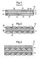
FIG. 1 is a schematic elevational cross-sectional view of a prior art solid oxide fuel cell assembly;FIG.2 is a schematic elevational cross-sectional view of an improved solid oxide fuel cell assembly in accordance with the invention;FIG. 3 is a schematic elevational cross-sectional view of a portion of an improved fuel cell stack in accordance with the invention;FIG. 4 is an isometric view of an interconnect plate and spacer assembly in accordance with the invention;FIG. 5 is a detailed cross-sectional view of a loop of the assembly shown inFIG. 4 ;FIG. 6 is a preferred embodiment of a loop of a spacer assembly;FIG. 7 is an isometric view of a simple lock wire weave;FIG. 8 is an isometric view of a twill wire weave;FIG. 9 is an isometric view of a plain Dutch wire weave;FIG. 10 is an isometric view of a twill Dutch wire weave;FIG. 11 is an isometric view of a twill Dutch double wire weave; andFIGS. 12 through 20 are plan views of various exemplary patterns for spacers in accordance with the invention.- Referring to
FIG. 1 , a priorart fuel cell 10 includes elements known in the art of solid-oxide fuel cells. The example shown is of a class of such fuel cells said to be "anode-supported" in that the anode is a structural element having the electrolyte and cathode deposited upon it. Element thicknesses as shown are not to scale. - Each
fuel cell 10 includes anelectrolyte element 12 separating ananodic element 14 and acathodic element 16. Each anode and cathode is in direct chemical contact with its respective surface of the electrolyte, and each anode and cathode has a respectivefree surface respective passageway Anode 14 faces and is electrically connected to aninterconnect 26 byfilaments 28 extending across but not blockingpassageway 22. Similarly,cathode 16 faces and is electrically connected to interconnect 30 byfilaments 32 extending across but not blockingpassageway 24. - Preferably,
interconnects - In operation,
reformate gas 34 is provided topassageway 22 and flows parallel to the surface of the anode across the anode in a first direction. Hydrogen and CO in the reformate gas diffuse into the anode to the interface with the electrolyte.Oxygen 36, typically in air, is provided topassageway 24 and flows parallel to the surface of the cathode in a second direction which can be orthogonal to the first direction of the reformate (second direction shown in the same direction as the first for simplicity inFIG. 1 ). Molecular oxygen gas (O2) diffuses into the cathode and is catalytically reduced to two O-2 anions by accepting four electrons from the cathode andinterconnect 30 viafilaments 32. The electrolyte is permeable to the O-2 anions which pass via electric field through the electrolyte and combine with four hydrogen atoms to form two water molecules, giving up four electrons to the anode andinterconnect 26 viafilaments 28. - Referring to
FIG. 4 , aninterconnect assembly 38 in accordance with the invention includes aninterconnect plate 40, analogous to either ofplates FIG. 1 , and a formed, three-dimensional,conductive spacer 42 disposed on one side ofplate 40. As shown inFIG. 4 ,spacer 42 may be formed into parallel corrugations havingarcuate peaks 44 andvalleys 46, the valleys making mechanical and electrical contact along at least a portion of their length with the surfaces ofplate 40. Preferably,valleys 46 are bonded to plate 40 as by resistance welding, laser welding, or brazing. Preferably, aspacer 42 is disposed on each side ofplate 40, as shown inFIG. 4 . Spacer 42 is preferably stamped in known fashion from wire mesh which may be woven in any convenient weave, as discussed further below. Preferably, the mesh is selected to provide both flexibility and resilience as well as conductivity. Referring toFIG. 5 , aloop 48 ofspacer 42 is shown in its non-compressed state 48'. After assembly into a fuel cell stack in known fashion,loop 48 is compressed intoshape 48" by contact with either an anode or a cathode, theheight 50 then representing the height of agas passageway valley 46 and the spacing betweenadjacent bends 46 may be varied to control the stiffness ofspacer 42.- In a currently preferred
embodiment 52,spacer 42 is formed having a "dual-compression" feature.First loop portions 54 are relatively rigid, being formed at a relatively high first includedangle 56 to plate 40, and providing good mechanical support betweeninterconnect plate 40 and either the anode or cathode during assembly to defineheight 50.Second loop portions 58 betweenfirst loop portions 54 are formed at a low second includedangle 59 to plate 40 and therefore are relatively easily compressed toheight 50 during assembly. The durability and resilience of the wire mesh ensures that good electrical contact is maintained over a very large plurality of points of contact on the electrode surfaces during all conditions of use and variation of gas flow space due to component tolerances. - The wire mesh may be formed in a variety of patterns, as desired for various degrees of stiffness, forming, and gas permeability, as well as bias in the folded wire. The warp and shute wires may be of different diameters or gauges. Further, it can be beneficial to include some percentage of high-conductivity shute wires; for example, making every other shute wire from silver or platinum in a mesh formed otherwise of appropriately resistant metal. Some suitable metals are stainless steel; nickel; nickel alloys including Monel, Hastelloy C-276, Incoloy Alloys 600 and 800, Nichrome, and Nichrome V; molybdenum, tantalum, and tungsten. Suitable wire mesh materials are available from, for example, Newark Wire Cloth Co., Newark, New Jersey, USA.
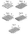
- Some exemplary weave patterns are shown in
FIGS. 7 through 11 . Other weave patterns are also comprehended by the invention. FIG. 7 shows asimple lock weave 60 wherein crimping of thewarp 62 andshute 64 wires is done in such a manner to actually 'lock' the wires together at their points of intersection, offering assurance of no wire movement.Weave 60 is currently preferred for use in formingassembly 38.FIG. 8 shows a twill weave 66 wherein eachwarp wire 62 and eachshute wire 64 passes successively over and under the two adjacent wires, in both the warp and shute directions. This over and under movement is shifted one wire with each pass of the shuttle. Twill weave 66 permits the weaving of heavier wires in varying meshes.FIG. 9 shows a plainDutch weave 68 wherein thewarp wires 62 are larger in diameter than theshute wires 64. The lighter shute wires are driven up close. This weave displays a tapered or wedge-shaped opening.FIG. 10 shows a twillDutch weave 70 combining the twill weave and Dutch weave described above. The largerdiameter warp wires 62 successively pass over and under the lighterdiameter shute wires 64. Each pass of the shute wires shifts the over and under movement one wire. The shute wires are driven up close, resulting in a tightly woven filter cloth with tapered or wedge shaped openings.FIG. 11 shows a twill Dutchdouble weave 72 very similar to twillDutch weave 70, but by proper selection of the wire sizes, theshute wires 64 actually overlap each other when driven up tight into position. This permits double the wires per inch in the shute direction.- Referring to
FIG. 2 , an improved fuel cell 10' is identical with priorart fuel cell 10 except thatinterconnect plates filaments interconnect plate assemblies 38. A portion of fuel cell 10' may be considered afuel cell module 74 which may then be combined with one or moresuch modules 74 to provide afuel cell stack 76 in known fashion, as shown inFIG. 3 (note that in bothFIGS. 2 and 3 , theloops 48 are not shown in the compressed configuration as described above and shown inFIG. 5 ). - The
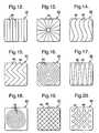
valleys 46 andpeaks 44 ofassembly 38 may be oriented at any angle to the flow ofgas conductive spacer 42 is comprehended by the invention. Some exemplary patterns are shown inFIGS. 12 through 20 , as follows:FIG. 12 , linear 78 (shown isometrically inFIG. 4 );FIG. 13 ,starburst radial 80 ;FIG. 14 , wavy 82;FIG. 15 , zig-zag 84:FIG. 16 , circular 86;FIG. 17 , tapered linear 88;FIG. 18 ,spiral 90;FIG. 19 , cross-hatched 92; andFIG. 20 , dimpled 94. In any such pattern, the heights of the non-compressed peaks and compressed peaks are substantially as shown inFIGS. 5 or 6 .
Claims (14)
- An electrically conduction spacer (42) for disposition in a fuel cell apparatus (10') between and in electrical contact with an electrode (14,16) thereof and an interconnect means (29,30), said spacer being formed from a woven metal mesh into a three-dimensional pattern (78,80,82,84,86,88,90,92,94) of peaks (44) and valleys (46) for making said electrical contacts, obtainable by stamping from a wire mesh which may be woven in any convenient weave.
- A spacer (42) in accordance with Claim 1 wherein said electrode is selected from the group consisting of anode (14) and cathode (16).
- A spacer (42) in accordance with Claim 1 wherein said spacer is a first spacer and is attached to a first surface (40) of said interconnect means to form an interconnect assembly (38).
- A spacer (42) in accordance with Claim 3 wherein said interconnect assembly (38) includes a second spacer substantially identical with said first spacer and attached to a second surface of said interconnect plate.
- A spacer (42) in accordance with Claim 1 wherein said metal mesh is woven of metal wires.
- A spacer (42) in accordance with Claim 5 wherein said metal wires are woven in a pattern (60,66,68,70,72).
- A spacer (42) in accordance with Claim 6 wherein said weave pattern is selected from the group consisting of simple lock weave (60), twill weave (66), plain Dutch weave (68), twill Dutch weave (70), and twill Dutch double weave (72).
- A spacer (42) in accordance with Claim 1 wherein said three-dimensional pattern is selected from the group consisting of linear (78), starburst radial (80), wavy (82), zig-zag (84), circular (86), tapered linear (88), spiral (90), cross-hatched (92), and dimpled (94).
- A spacer (42) in accordance with Claim 1 wherein said metal is selected from the group consisting of Hastelloy C, Haynes 230, a stainless steel, nickel, nickel alloys, molybdenum, tantalum, and tungsten.
- A spacer (42) in accordance with Claim 1 wherein said interconnect means is a plate (40) and said spacer engages said plate at a first included angle (56) to said plate at a plurality of locations on said plate and wherein said spacer pattern includes a second included angle (59) to said plate at a height from said plate between two adjacent first included angles, said second included angle being smaller than said first included angle.
- A spacer (42) in accordance with Claim 1 wherein said three-dimensional pattern has a compressed height (48") defining the height of a gas flow passage in said fuel cell apparatus.
- An interconnect assembly (38) for use in a fuel cell stack (76), comprising:a) an interconnect plate (40); andb) a first electrically conductive spacer (42) formed from a woven metal mesh into a three-dimensional pattern (78,80,02,84,86,88,90,92,94) of peaks (44) and valleys (46) for making electrical contact with said plate and an electrode (14,16) in said fuel cell stack, said first spacer (42) being attached to a first side of said plate.
- An interconnect assembly (38) in accordance with Claim 12 further comprising a second electrically conductive spacer attached to a second side of said plate.
- A fuel cell stack (74) comprising at least first and second fuel cell modules (74) conjoined by an interconnect assembly (38) including a plate (40) and first and second electrically conductive spacers (42) attached to first and second sides of said plate, said spacers (42) being formed from a woven metal mesh into a three-dimensional pattern (78,80,82,84,86,88,90,92,94) of peaks (44) and valleys (46) for making electrical contact with said plate and with electrodes (14,16) in said first and second fuel cell modules (74).
Applications Claiming Priority (2)
| Application Number | Priority Date | Filing Date | Title |
|---|---|---|---|
| US305881 | 1999-05-05 | ||
| US10/305,881US8048587B2 (en) | 2002-11-27 | 2002-11-27 | Compliant current collector for fuel cell anode and cathode |
Publications (2)
| Publication Number | Publication Date |
|---|---|
| EP1434294A1 EP1434294A1 (en) | 2004-06-30 |
| EP1434294B1true EP1434294B1 (en) | 2008-09-03 |
Family
ID=32325550
Family Applications (1)
| Application Number | Title | Priority Date | Filing Date |
|---|---|---|---|
| EP03078594AExpired - LifetimeEP1434294B1 (en) | 2002-11-27 | 2003-11-17 | Compliant current collector for fuel cell anode and cathode |
Country Status (3)
| Country | Link |
|---|---|
| US (1) | US8048587B2 (en) |
| EP (1) | EP1434294B1 (en) |
| DE (1) | DE60323324D1 (en) |
Cited By (1)
| Publication number | Priority date | Publication date | Assignee | Title |
|---|---|---|---|---|
| DE102010026310A1 (en) | 2010-07-06 | 2012-01-12 | Uhde Gmbh | Electrode for electrolysis cells |
Families Citing this family (49)
| Publication number | Priority date | Publication date | Assignee | Title |
|---|---|---|---|---|
| US6926988B2 (en)* | 2000-09-27 | 2005-08-09 | Proton Energy Systems, Inc. | Apparatus and method for maintaining compression of the active area in an electrochemical cell |
| US20040200187A1 (en)* | 2002-11-27 | 2004-10-14 | Warrier Sunil G. | Compliant, strain tolerant interconnects for solid oxide fuel cell stack |
| US20040265666A1 (en)* | 2003-06-27 | 2004-12-30 | Weil K. Scott | Solid oxide fuel cell frames and method of manufacture |
| US7767329B2 (en)* | 2003-11-17 | 2010-08-03 | Adaptive Materials, Inc. | Solid oxide fuel cell with improved current collection |
| US8343689B2 (en)* | 2003-11-17 | 2013-01-01 | Adaptive Materials, Inc. | Solid oxide fuel cell with improved current collection |
| JP4218569B2 (en)* | 2004-03-30 | 2009-02-04 | 株式会社エクォス・リサーチ | Separator and fuel cell using the same |
| KR100760132B1 (en)* | 2005-02-28 | 2007-09-18 | 산요덴키가부시키가이샤 | Composite membrane and fuel cell using composite membrane |
| DE102005014077B4 (en)* | 2005-03-23 | 2012-05-24 | Forschungszentrum Jülich GmbH | Interconnector for high-temperature fuel cells and method for its production and method for operating a fuel cell |
| US7601450B2 (en)* | 2005-03-23 | 2009-10-13 | Delphi Technologies, Inc. | Hybrid interconnect for a solid-oxide fuel cell stack |
| US8021795B2 (en)* | 2005-04-07 | 2011-09-20 | General Electric Company | Method for manufacturing solid oxide electrochemical devices |
| US7781123B2 (en)* | 2005-06-06 | 2010-08-24 | Delphi Technologies, Inc. | Method and apparatus for forming electrode interconnect contacts for a solid-oxide fuel cell stack |
| WO2007038132A1 (en)* | 2005-09-21 | 2007-04-05 | Jones Eric T | Fuel cell device |
| JP4910347B2 (en)* | 2005-09-27 | 2012-04-04 | トヨタ自動車株式会社 | Fuel cell module with current collecting electrode that also serves as a spacer |
| US20070134540A1 (en)* | 2005-12-12 | 2007-06-14 | General Electric Company | Solid oxide electrochemical devices having a dimensionally stable bonding agent to bond an anode to anode interconnect and methods |
| WO2008133607A2 (en)* | 2006-04-03 | 2008-11-06 | Bloom Energy Corporation | Fuel cell stack components and materials |
| US7951509B2 (en)* | 2006-04-03 | 2011-05-31 | Bloom Energy Corporation | Compliant cathode contact materials |
| GB2440038B (en)* | 2006-07-07 | 2009-04-15 | Ceres Ip Co Ltd | Metal substrate for fuel cells |
| JP2008140549A (en)* | 2006-11-29 | 2008-06-19 | Shinko Electric Ind Co Ltd | Current collector for cell stack of fuel cell and direct flame type fuel cell using it |
| US20100129731A1 (en)* | 2006-12-28 | 2010-05-27 | Utc Power Corporation | Multi-wire, long-life interconnects for fuel cell stacks |
| ITMI20071375A1 (en)* | 2007-07-10 | 2009-01-11 | Uhdenora Spa | ELASTIC CURRENT MANIFOLD FOR ELECTROCHEMICAL CELLS |
| TWI479730B (en)* | 2009-03-20 | 2015-04-01 | Bloom Energy Corp | Crack free sofc electrolyte |
| KR20130015977A (en)* | 2011-08-05 | 2013-02-14 | 삼성에스디아이 주식회사 | Fuel cell stack and manufacturing method of the same |
| KR101301354B1 (en)* | 2011-09-27 | 2013-08-29 | 삼성전기주식회사 | Solid oxide fuel cell and solid oxide fuel cell module |
| TWI552417B (en) | 2011-11-17 | 2016-10-01 | 博隆能源股份有限公司 | Multi-layer coating that provides corrosion resistance to zirconia-based electrolytes |
| US9196909B2 (en) | 2011-11-18 | 2015-11-24 | Bloom Energy Corporation | Fuel cell interconnect heat treatment method |
| US9452475B2 (en) | 2012-03-01 | 2016-09-27 | Bloom Energy Corporation | Coatings for SOFC metallic interconnects |
| EP2824755B1 (en)* | 2012-03-09 | 2022-05-11 | Nissan Motor Co., Ltd. | Air battery |
| US9847520B1 (en) | 2012-07-19 | 2017-12-19 | Bloom Energy Corporation | Thermal processing of interconnects |
| WO2014036058A1 (en) | 2012-08-29 | 2014-03-06 | Bloom Energy Corporation | Interconnect for fuel cell stack |
| US9478812B1 (en) | 2012-10-17 | 2016-10-25 | Bloom Energy Corporation | Interconnect for fuel cell stack |
| KR20140053568A (en)* | 2012-10-26 | 2014-05-08 | 삼성전기주식회사 | Solid oxide fuel cell module |
| CN104769762A (en) | 2012-11-06 | 2015-07-08 | 博隆能源股份有限公司 | Improved interconnect and end plate designs for fuel cell stacks |
| US10069162B2 (en)* | 2013-02-07 | 2018-09-04 | Ngk Spark Plug Co., Ltd. | Fuel cell |
| WO2014186126A1 (en) | 2013-05-16 | 2014-11-20 | Bloom Energy Corporation | Corrosion resistant barrier layer for a solid oxide fuel cell stack and method of making thereof |
| US9356300B2 (en) | 2013-09-25 | 2016-05-31 | Delphi Technologies, Inc. | Fuel cell electrode interconnect contact material encapsulation and method |
| TW201530886A (en) | 2013-10-01 | 2015-08-01 | Bloom Energy Corp | Pre-formed powder delivery to powder press machine |
| WO2015080889A1 (en) | 2013-11-27 | 2015-06-04 | Bloom Energy Corporation | Fuel cell interconnect with reduced voltage degradation over time |
| US10079393B1 (en) | 2014-01-09 | 2018-09-18 | Bloom Energy Corporation | Method of fabricating an interconnect for a fuel cell stack |
| WO2015130644A1 (en) | 2014-02-25 | 2015-09-03 | Bloom Energy Corporation | Composition and processing of metallic interconnects for sofc stacks |
| US9923211B2 (en) | 2014-04-24 | 2018-03-20 | Bloom Energy Corporation | Fuel cell interconnect with reduced voltage degradation over time |
| US10427070B1 (en)* | 2015-06-17 | 2019-10-01 | William S. Cagle | Triple layer non-plugging screen |
| WO2017010436A1 (en)* | 2015-07-16 | 2017-01-19 | 住友電気工業株式会社 | Fuel cell |
| KR102546579B1 (en)* | 2015-07-16 | 2023-06-21 | 스미토모덴키고교가부시키가이샤 | Fuel cell |
| KR101905971B1 (en)* | 2016-09-09 | 2018-10-08 | 현대자동차주식회사 | Fuel cell and manufacturing method thereof |
| USD959155S1 (en)* | 2017-02-09 | 2022-08-02 | Curver Luxembourg Sarl | Sheet material |
| US10763533B1 (en) | 2017-03-30 | 2020-09-01 | Bloom Energy Corporation | Solid oxide fuel cell interconnect having a magnesium containing corrosion barrier layer and method of making thereof |
| US20190106876A1 (en)* | 2017-10-10 | 2019-04-11 | Linus Industries, LLC | Triaxial weave for the production of stiff structural manifolds for use in structures and weaving method thereof |
| US12344948B2 (en)* | 2019-03-18 | 2025-07-01 | Asahi Kasei Kabushiki Kaisha | Elastic mattress and electrolyzer |
| KR102714957B1 (en)* | 2021-12-28 | 2024-10-08 | 주식회사진영정기 | Current collector for solid oxide fuel cell to prevent structural deformation |
Family Cites Families (41)
| Publication number | Priority date | Publication date | Assignee | Title |
|---|---|---|---|---|
| US399616A (en)* | 1889-03-12 | Screen for bolting flour | ||
| US1078380A (en)* | 1912-12-23 | 1913-11-11 | Tyler Co W S | Method of forming woven-wire fabrics. |
| US1139469A (en)* | 1914-02-20 | 1915-05-11 | Winfield Scott Potter | Woven screen. |
| US1147279A (en)* | 1914-05-25 | 1915-07-20 | Ernest J Sweetland | Filter medium or other article of manufacture. |
| US1525532A (en)* | 1923-03-01 | 1925-02-10 | Inland Engineering Company | Screen |
| US1829498A (en)* | 1927-12-27 | 1931-10-27 | Tyler Co W S | Woven wire screen and method of making same |
| US1907056A (en)* | 1932-01-22 | 1933-05-02 | B Greening Wire Co Ltd | Wire screen |
| US2160715A (en)* | 1936-06-19 | 1939-05-30 | Fidelity Machine Co | Machine for making braided wire netting |
| US2271662A (en)* | 1939-01-17 | 1942-02-03 | Rubissow George Alexis | Filtering element and new method for its manufacture |
| US2257993A (en)* | 1939-11-16 | 1941-10-07 | Leonard A Young | Method of manufacturing wire screens |
| US2874730A (en)* | 1955-12-01 | 1959-02-24 | Tyler Co W S | Woven structural material |
| NL302791A (en)* | 1963-01-02 | |||
| FR1367534A (en)* | 1963-05-17 | 1964-07-24 | Comp Generale Electricite | Electric fuel cell |
| US3432363A (en)* | 1963-11-12 | 1969-03-11 | Allis Chalmers Mfg Co | High temperature fuel cell electrolyte carrier |
| GB1169735A (en)* | 1966-03-07 | 1969-11-05 | Nat Standard Company Ltd | Improved Gas Filter |
| US3673058A (en)* | 1969-04-07 | 1972-06-27 | Hexcel Corp | Honeycomb having laminates of unidirectional strands |
| US3659402A (en)* | 1970-03-30 | 1972-05-02 | Howard Alliger | Multiple screen construction |
| US4342792A (en)* | 1980-05-13 | 1982-08-03 | The British Petroleum Company Limited | Electrodes and method of preparation thereof for use in electrochemical cells |
| US4436592A (en)* | 1983-04-25 | 1984-03-13 | Rohr Industries, Inc. | Method of selectively electroplating the nodes of dimpled titanium material |
| US5029779A (en)* | 1988-06-06 | 1991-07-09 | N.V. Bekaert S.A. | Welded netting with deformed stretching wires |
| DE3916713A1 (en)* | 1989-05-23 | 1990-11-29 | Hoechst Ag | THREE-DIMENSIONALLY MOLDED, METALLIZED NETWORK, METHOD FOR PRODUCING IT AND ITS USE |
| DE3922425A1 (en)* | 1989-07-07 | 1991-01-17 | Hoechst Ag | ELECTRODE FOR GALVANIC PRIMARY AND SECONDARY ELEMENTS |
| EP0424732A1 (en)* | 1989-10-27 | 1991-05-02 | Asea Brown Boveri Ag | Current conduction element for stacked hightemperature fuel cells and method of manufacture |
| DE4110285A1 (en)* | 1991-03-28 | 1992-10-01 | Schwaebische Huettenwerke Gmbh | FILTER OR CATALYST BODY |
| US5527590A (en)* | 1993-03-18 | 1996-06-18 | Priluck; Jonathan | Lattice block material |
| DE19517443C2 (en)* | 1995-05-12 | 1997-07-10 | Mtu Friedrichshafen Gmbh | Corrosion-resistant current collector |
| IT1284072B1 (en)* | 1996-06-26 | 1998-05-08 | De Nora Spa | ELECTROCHEMICAL DIAPHRAGM CELL FITTED WITH GASEOUS DIFFUSION ELECTRODES CONTACTED BY SMOOTH AND POROUS METALLIC CURRENT HOLDERS |
| US5798187A (en)* | 1996-09-27 | 1998-08-25 | The Regents Of The University Of California | Fuel cell with metal screen flow-field |
| AUPO897897A0 (en) | 1997-09-05 | 1997-09-25 | Ceramic Fuel Cells Limited | An interconnect device for a fuel cell assembly |
| US6096450A (en)* | 1998-02-11 | 2000-08-01 | Plug Power Inc. | Fuel cell assembly fluid flow plate having conductive fibers and rigidizing material therein |
| AUPQ078899A0 (en) | 1999-06-04 | 1999-06-24 | Ceramic Fuel Cells Limited | A fuel cell gas separator |
| AU5381200A (en)* | 1999-06-09 | 2001-01-02 | Questair Technologies, Inc. | Rotary pressure swing adsorption apparatus |
| US6559094B1 (en)* | 1999-09-09 | 2003-05-06 | Engelhard Corporation | Method for preparation of catalytic material for selective oxidation and catalyst members thereof |
| US6379831B1 (en)* | 2000-08-02 | 2002-04-30 | Siemens Westinghouse Power Corporation | Expanded nickel screen electrical connection supports for solid oxide fuel cells |
| US6387140B1 (en)* | 2000-08-09 | 2002-05-14 | Aaf-Mcquay, Inc. | Fluid stream velocity distribution control |
| US6770395B2 (en)* | 2000-10-23 | 2004-08-03 | Materials And Systems Research, Inc. | Internally manifolded, planar solid oxide fuel cell (SOFC) stack with an inexpensive interconnect |
| US7351468B2 (en)* | 2000-10-26 | 2008-04-01 | E. I. Du Pont De Nemours And Company | Interlayers for laminated safety glass with superior de-airing and laminating properties and process for making the same |
| USD449741S1 (en)* | 2000-12-19 | 2001-10-30 | Royal Ten Cate Usa, Inc. | Fabric |
| US7122266B2 (en)* | 2001-09-13 | 2006-10-17 | Ngk Insulators, Ltd. | Holding member for holding an electrochemical cell, a holding substrate for the same, an electrochemical system and a connecting member for electrochemical cells |
| CN100346923C (en)* | 2002-02-14 | 2007-11-07 | 麦克内尔-Ppc股份有限公司 | Method of mfg. floor supporting part for forming porous film |
| US7157172B2 (en)* | 2003-05-23 | 2007-01-02 | Siemens Power Generation, Inc. | Combination nickel foam expanded nickel screen electrical connection supports for solid oxide fuel cells |
- 2002
- 2002-11-27USUS10/305,881patent/US8048587B2/enactiveActive
- 2003
- 2003-11-17EPEP03078594Apatent/EP1434294B1/ennot_activeExpired - Lifetime
- 2003-11-17DEDE60323324Tpatent/DE60323324D1/ennot_activeExpired - Lifetime
Cited By (2)
| Publication number | Priority date | Publication date | Assignee | Title |
|---|---|---|---|---|
| DE102010026310A1 (en) | 2010-07-06 | 2012-01-12 | Uhde Gmbh | Electrode for electrolysis cells |
| WO2012003969A1 (en) | 2010-07-06 | 2012-01-12 | Thyssenkrupp Uhde Gmbh. | Electrode for electrolysis cells |
Also Published As
| Publication number | Publication date |
|---|---|
| DE60323324D1 (en) | 2008-10-16 |
| US20040101742A1 (en) | 2004-05-27 |
| EP1434294A1 (en) | 2004-06-30 |
| US8048587B2 (en) | 2011-11-01 |
Similar Documents
| Publication | Publication Date | Title |
|---|---|---|
| EP1434294B1 (en) | Compliant current collector for fuel cell anode and cathode | |
| US20050037252A1 (en) | Tubular solid oxide fuel cells | |
| US7449261B2 (en) | Holding member for holding an electrochemical cell, a holding substrate for the same, an electrochemical system and a connecting member for electrochemical cells | |
| US20050136312A1 (en) | Compliant fuel cell system | |
| WO1998013891A1 (en) | Fuel cell with metal screen flow-field | |
| EP3346027A1 (en) | Electrochemical hydrogen pump | |
| KR20070091324A (en) | High Specific Power Solid Oxide Fuel Cell Stack | |
| EP2904656B1 (en) | Resilient flow structures for electrochemical cell | |
| JP2024519724A (en) | Method for manufacturing SOEC/SOFC type solid oxide stacks and related stacks | |
| JP7470039B2 (en) | Metal plate manufacturing method | |
| EP1391953B1 (en) | Laminated structure of flat plate type solid oxide fuel cell | |
| EP1466376A2 (en) | Metal stack for fuel cells or electrolysers | |
| EP4181243A2 (en) | Fuel cell interconnect optimized for operation in hydrogen fuel | |
| US20140045097A1 (en) | Current collector for solid oxide fuel cell and solid oxide fuel cell having the same | |
| JP2008103142A (en) | Gas diffusion layer for fuel cell, method for producing the same, and polymer electrolyte fuel cell using the same | |
| US20230243046A1 (en) | Flattened wire mesh electrode for use in an electrolyzer cell | |
| JPH01313855A (en) | Electrode member for solid electrolyte type fuel cell, its manufacture and solid electrolyte type fuel cell | |
| JP5401438B2 (en) | Flat type solid electrolyte fuel cell | |
| JP4023669B2 (en) | Electrochemical equipment | |
| EP3796442B1 (en) | Fuel cell system | |
| US20060068261A1 (en) | Fuel cell systems | |
| US20250046847A1 (en) | Solid oxide electrochemical cell stack | |
| JPH01313856A (en) | Electrode member for solid electrolyte type fuel cell, its manufacture and solid electrolyte type fuel cell | |
| US20250323304A1 (en) | Electrochemical cell stacks including multi-diameter mesh contact layer | |
| JP2025122636A (en) | Electrochemical cell stack including a multi-diameter mesh contact layer |
Legal Events
| Date | Code | Title | Description |
|---|---|---|---|
| PUAI | Public reference made under article 153(3) epc to a published international application that has entered the european phase | Free format text:ORIGINAL CODE: 0009012 | |
| AK | Designated contracting states | Kind code of ref document:A1 Designated state(s):AT BE BG CH CY CZ DE DK EE ES FI FR GB GR HU IE IT LI LU MC NL PT RO SE SI SK TR | |
| AX | Request for extension of the european patent | Extension state:AL LT LV MK | |
| 17P | Request for examination filed | Effective date:20041230 | |
| 17Q | First examination report despatched | Effective date:20050131 | |
| AKX | Designation fees paid | Designated state(s):DE FR GB | |
| GRAP | Despatch of communication of intention to grant a patent | Free format text:ORIGINAL CODE: EPIDOSNIGR1 | |
| GRAS | Grant fee paid | Free format text:ORIGINAL CODE: EPIDOSNIGR3 | |
| RIN1 | Information on inventor provided before grant (corrected) | Inventor name:PAXTON, DEAN Inventor name:WEIL , KENNETH SCOTT Inventor name:HALTINER JR., KARL JACOB Inventor name:MUKERJEE, SUBHASISH Inventor name:SIMPKINS, HASKELL | |
| GRAA | (expected) grant | Free format text:ORIGINAL CODE: 0009210 | |
| RAP1 | Party data changed (applicant data changed or rights of an application transferred) | Owner name:DELPHI TECHNOLOGIES, INC. Owner name:BATTELLE MEMORIAL INSTITUTE | |
| AK | Designated contracting states | Kind code of ref document:B1 Designated state(s):DE FR GB | |
| REG | Reference to a national code | Ref country code:GB Ref legal event code:FG4D | |
| REF | Corresponds to: | Ref document number:60323324 Country of ref document:DE Date of ref document:20081016 Kind code of ref document:P | |
| PLBE | No opposition filed within time limit | Free format text:ORIGINAL CODE: 0009261 | |
| STAA | Information on the status of an ep patent application or granted ep patent | Free format text:STATUS: NO OPPOSITION FILED WITHIN TIME LIMIT | |
| 26N | No opposition filed | Effective date:20090604 | |
| PGFP | Annual fee paid to national office [announced via postgrant information from national office to epo] | Ref country code:DE Payment date:20091112 Year of fee payment:7 | |
| PGFP | Annual fee paid to national office [announced via postgrant information from national office to epo] | Ref country code:FR Payment date:20091123 Year of fee payment:7 Ref country code:GB Payment date:20091111 Year of fee payment:7 | |
| GBPC | Gb: european patent ceased through non-payment of renewal fee | Effective date:20101117 | |
| REG | Reference to a national code | Ref country code:FR Ref legal event code:ST Effective date:20110801 | |
| REG | Reference to a national code | Ref country code:DE Ref legal event code:R119 Ref document number:60323324 Country of ref document:DE Effective date:20110601 Ref country code:DE Ref legal event code:R119 Ref document number:60323324 Country of ref document:DE Effective date:20110531 | |
| PG25 | Lapsed in a contracting state [announced via postgrant information from national office to epo] | Ref country code:FR Free format text:LAPSE BECAUSE OF NON-PAYMENT OF DUE FEES Effective date:20101130 | |
| PG25 | Lapsed in a contracting state [announced via postgrant information from national office to epo] | Ref country code:GB Free format text:LAPSE BECAUSE OF NON-PAYMENT OF DUE FEES Effective date:20101117 | |
| PG25 | Lapsed in a contracting state [announced via postgrant information from national office to epo] | Ref country code:DE Free format text:LAPSE BECAUSE OF NON-PAYMENT OF DUE FEES Effective date:20110531 |