EP1434114B1 - Watch with a housing having a bottom or hatch cover with bayonet mount that can be opened manually - Google Patents
Watch with a housing having a bottom or hatch cover with bayonet mount that can be opened manuallyDownload PDFInfo
- Publication number
- EP1434114B1 EP1434114B1EP02080668AEP02080668AEP1434114B1EP 1434114 B1EP1434114 B1EP 1434114B1EP 02080668 AEP02080668 AEP 02080668AEP 02080668 AEP02080668 AEP 02080668AEP 1434114 B1EP1434114 B1EP 1434114B1
- Authority
- EP
- European Patent Office
- Prior art keywords
- cover
- watch
- watch according
- annular portion
- case
- Prior art date
- Legal status (The legal status is an assumption and is not a legal conclusion. Google has not performed a legal analysis and makes no representation as to the accuracy of the status listed.)
- Expired - Lifetime
Links
Images


Classifications
- G—PHYSICS
- G04—HOROLOGY
- G04C—ELECTROMECHANICAL CLOCKS OR WATCHES
- G04C10/00—Arrangements of electric power supplies in time pieces
- G04C10/02—Arrangements of electric power supplies in time pieces the power supply being a radioactive or photovoltaic source
- G—PHYSICS
- G04—HOROLOGY
- G04G—ELECTRONIC TIME-PIECES
- G04G17/00—Structural details; Housings
- G04G17/02—Component assemblies
- G04G17/04—Mounting of electronic components
- G—PHYSICS
- G04—HOROLOGY
- G04B—MECHANICALLY-DRIVEN CLOCKS OR WATCHES; MECHANICAL PARTS OF CLOCKS OR WATCHES IN GENERAL; TIME PIECES USING THE POSITION OF THE SUN, MOON OR STARS
- G04B37/00—Cases
- G04B37/0008—Cases for pocket watches and wrist watches
- G04B37/005—Cases for pocket watches and wrist watches with cover or protection device which can be completely removed, either by lifting off or by sliding, or by turning (protection covers, protection cases also against humidity)
- G—PHYSICS
- G04—HOROLOGY
- G04B—MECHANICALLY-DRIVEN CLOCKS OR WATCHES; MECHANICAL PARTS OF CLOCKS OR WATCHES IN GENERAL; TIME PIECES USING THE POSITION OF THE SUN, MOON OR STARS
- G04B37/00—Cases
- G04B37/08—Hermetic sealing of openings, joints, passages or slits
- G04B37/11—Hermetic sealing of openings, joints, passages or slits of the back cover of pocket or wrist watches
- G—PHYSICS
- G04—HOROLOGY
- G04C—ELECTROMECHANICAL CLOCKS OR WATCHES
- G04C10/00—Arrangements of electric power supplies in time pieces
Definitions
- the present inventionrelates to a watch having a box which contains an electronic clockwork movement and an electric battery comprising at least one battery or at least one accumulator, the box having a circular lower opening which makes it possible to introduce and extract the battery and which is sealingly closed by a removable cover provided with bayonet fixing means, the cover having a plate, which covers a housing for the battery and forms at least a portion of the bottom of the box, and a substantially cylindrical annular portion which extends perpendicularly to said plate and fits into said opening, said annular portion carrying at least two locks forming part of the bayonet fixing means.
- the removable cover that closes the hatch giving access to the batterycan either constitute the bottom of the watch case, or close the opening in a bottom fixed itself to the middle of the box or made of a single piece with this build.
- electrical batterya source of electrical energy that may include one or more single-use batteries, or one or more rechargeable batteries.
- the inventionapplies particularly, but not exclusively, to electronic watches comprising one or more additional devices that consume electrical energy, such as, for example, a communication device by radio, optical or acoustic transmission, a measuring device using a pressure sensor or the like, a navigation device, an electronic camera, an electronic organizer, etc.
- electrical energysuch as, for example, a communication device by radio, optical or acoustic transmission, a measuring device using a pressure sensor or the like, a navigation device, an electronic camera, an electronic organizer, etc.
- the energy consumption of these additional devicesrequires the inclusion in the watch of a rather large electric battery, comprising either several batteries or accumulators, or a battery or a large accumulator.
- the necessary opening in the bottom of the box to give access to this batterycan then become very large and extend over most or all of the bottom surface.
- the removable cover closing this openingis fixed by a bayonet system, the size of the elements of this system and the associated sealing members can cause problems.
- the document US 2002/0064098discloses a removable cover providing access to a battery which is sealingly attached by means of a hook ring.
- the document CH 211142discloses several modes of embodiment of a two bayonet type fixing device forming a sealed box.
- the patent application EP 272,515describes a wristwatch of the kind indicated in the preamble above and having at the rear a large cover to provide access to the electric battery.
- the circular opening of the bottom of the boxhas a diameter substantially larger than the diameter of the circle circumscribing the assembly formed by the watch movement and the battery.
- the bayonet fixing meansare arranged outside this circle, at a level above the lower face of the movement.
- the cylindrical annular portion of the lidserves to stiffen the lid and to bring to its top the latches of the bayonet fixing device, which are directed outwardly so as to be able to hold on to the inside edges of the middle part of the box L sealing around the opening is provided in a conventional manner, by means of an O-ring disposed in a groove of the lower face of the middle part and compressed axially by the cover.
- the subject of the present inventionis a watch arranged in such a way as to avoid to a large extent the aforementioned drawbacks, in particular so as to be able to limit the size of the cover with respect to the circumscribed circle of the battery when it is particularly bulky, for example when it includes several batteries or accumulators.
- a watch of the kind indicated in the preamblewherein said lid locks extend inwardly of the substantially cylindrical annular portion of the cover and cling to the shoulders of at least one fixed element mounted in the box, said shoulders being inside said annular portion when the lid is attached to the box.
- the arrangement of the locks towards the inside of the annular portion of the coveradvantageously makes it possible to arrange the seal around this annular part, so that the lining is pressed radially against a circular surface forming the periphery of said opening, in particular a substantially cylindrical surface.
- the openingmay further have a flared inlet to provide radial compression of the seal during the introduction of the lid.
- This arrangement of the sealtakes up very little space radially and thus makes it possible to significantly reduce the width of the cover with respect to the prior art mentioned above. Thanks to the radial compression of the seal, the seal is guaranteed even if the lid has not been fully turned when it is put in place, and furthermore the compression of the seal hardly induces extra efforts on locks.
- engagement meansare disposed on a peripheral portion of the lid so as to allow a user to manually operate the lid without a specific tool.
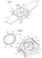
- the figure 1represents in perspective a wristwatch 1 comprising a box 2 of non-circular shape, closed above it by a lens 6 disposed above a dial for an analog display of the hour by means of needles 4 and 5 driven by a electronic watch movement.
- the dialcan also have a window for a digital or alphanumeric display 7.
- One or more control members 8are arranged on the box.
- the wristwatchcan be placed around the wrist by means of two strands of bracelet 10 and 11 attached to the middle of the box 2 and joined by a clasp of known type.
- the watch case 2in particular the underside of the watch case 2.
- itis made of a one-piece construction comprising a middle part 13 and a bottom 14, in which is formed a circular opening 15 serving as a trap door. access to the electric battery (not shown in this figure).
- the peripheral wall of the opening 15has a substantially cylindrical circular surface 16.
- the bottom-middle of the watch case 2is equipped with fastening members 17 and 18 for attaching it to the strands 10 and 11 of the bracelet.
- the opening 15is sealingly closed by a removable circular cover 20 which, in the view of the figure 2 , has been removed to show a battery holder 22 fixedly mounted inside the box 2.
- the cover 20, when it is placed in the opening 15,is fixed to the support 22 by a device fixing the bayonet type, which will be described in detail later.
- the support 22comprises two circular housings 23 and 24 for two batteries forming together the electric battery for supplying the circuits contained in the watch.
- the box and the lidare preferably metallic, but other materials are conceivable.
- the watch 6 of the iceis carried by a two-piece bezel 26 and 27, mounted on the top of the middle part 13 with a seal 28.
- an electronic clockwork 30comprising in particular a quartz resonator 31 and an electric motor 32 which actuates the needles 4 and 5.
- These elementsare mounted on a printed circuit board 33 which is fixed in the box by conventional means, including a plastic plate 34 which supports the dial 29.
- This additional devicemay be of one of the types mentioned above and comprise, for example, one or more integrated circuits 38 and memories 39. It is supplied with electrical energy, just like the components mounted on the card 33, by the electric battery formed by the two batteries 41 and 42 housed in the support 22 and connected in series using blades. embedded in this support, which is made of synthetic insulating material. In order to simplify the drawing, the electrical connections between the batteries 41 and 42, the support 22, the card 37 and the card 33 are not represented. Of course, it would also be possible to provide separate power supplies, one of the batteries supplying the components mounted on the card 33 and the other the components mounted on the card 37.
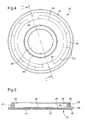
- the removable cover 20has a circular plate 44 which covers the entire opening 15 of the bottom of the box and which has a peripheral portion 45 thicker than its central portion. This peripheral portion forms a flange which is applied against the flat lower face 46 of the bottom 14 of the box, when the lid 20 is in the closed position.
- Two notches 47are formed in the outer face of the peripheral portion 45 to allow a user to manually rotate the cover by means of his or her nails or a common object such as a wrench or a buckle of the clasp of the wristband of the watch .
- a knurlingcould be provided as a manual gripping means on the peripheral portion of the lid.
- an electro-acoustic transducer 48preferably composed of piezoelectric elements, is glued to the central part of the plate 44 in order to make it vibrate, to transmit an acoustic and / or tactile signal. to the bearer of the watch.
- a bead 49is provided around the transducer 48 to improve the vibratory regime of the plate 44.
- the cover 22has a substantially cylindrical annular portion 50 whose outer face has a groove 51 for receiving an annular seal 52 formed in this case by an elastomeric O-ring. To reduce friction, this seal can be made of a self-lubricating material.
- the groove 51is closed upwards by a flat metal washer 54 which is welded at points 53 to the top of the annular cover portion 50.
- the outer diameter of this washeris substantially equal to that of the cylindrical outer face 55 of the annular portion 50.
- the washer 54has two radially inwardly projecting portions which are diametrically opposed and form two latches 56 of the fastener device. bayonet lid. In this case, the two latches 56 are flat and located in the same plane as the rest of the washer 54, but in other embodiments they could be inclined or folded in Z, as needed. On the other hand, the number of locks 56 could obviously be greater than two.
- the figure 6shows the battery holder 22 seen from below.
- Thisis a molded piece made of rigid and insulating synthetic material, which is held in position inside the watch case by pressing against the bottom 14 and using feet 60 and 61. particular in the figure 3 that each foot 61 fits into a hole one-eyed 62 from the bottom of the box. We also see that this foot is secured to a projecting portion 63 of the support, which holds by pinch one of the contact blades 64 which provide the connection between the battery and the electrical circuits of the watch.
- Other blades of this kindare housed in appropriate recesses of the support 22, in particular those bearing the references 65 to 67 in the figure 6 .
- the recess 67contains one or more blades connecting the transducer 48 to its control circuit.
- the support 22also serves to retain the removable cover 20 in place and it comprises for this purpose the fixed elements of the bayonet fixing device.
- These elementscomprise two shoulders 70 and 71 located on the upper face of two flanges 72 and 73 of the support 22 which are directed outwards.
- the shoulders 70 and 71have in plan a short arcuate shape and they may be slightly inclined longitudinally to pull the cover towards the inside of the box. Above these shoulders are respective notches 74 and 75 in which the latches 56 of the lid 20 can pass.
- the fixed elements 72 to 75 of the bayonet fixing device, as well as the free spaces 76 and 77 allowing the passage of the locks 56 in the axial direction when the lid 20 is inserted into the box,are all located at places which are not occupied by the battery formed by the batteries taking place in dwellings 23 and 24.
- FIG 2it is observed that these elements are still within a circle 80 circumscribed to the battery when it is seen in plan.
- each batteryextends to a short distance of the annular portion 50 of the lid.
- the diameter of the opening 15being only a little larger than that of the circumscribed circle 80, to a sufficient extent to allow the thickness of the with cylindrical annular portion 50 of the lid. Since, furthermore, the outer edge of the lid does not need to protrude much beyond the periphery of the opening 15, the latter can be as large as possible, taking into account the dimensions of the bottom 14 of the box, and thus give access to a large battery.
- the lid 20ensures excellent sealing of the bottom of the box in all circumstances.
- the flared inlet 81 thereofgradually crushes the elastomer seal 52, which is then compressed radially permanently between the annular portion 50 of the cover and the fixed cylindrical surface 16 even before the lid is fully inserted into the box.
- the coveris then rotated to engage the latches 56 on the shoulders 70 and 71, which will pull the lid until its edge bears against the lower face 46 of the bottom, the sealing conditions do not do not change and the compression of the seal 52 does not induce any effort on the locks 56 or on the support 22. This is obviously the same during the opening operation of the lid.
- the figure 7schematically represents an embodiment of a watch in which the removable cover 20 is entirely the bottom of the watch case, its peripheral portion 45 covering the lower face 82 of the middle part 13 and being pressed against it under the effect of the bayonet fixing device of the lid.
- the inner locks 56 of the covercling to any fixed support 83 mounted inside the box, each resting on a shoulder 71 of a flange 73 of the support as in the previous example.
- the support 83is held in abutment against a shoulder 84 of the caseband, for example by conventional flat flanges 85 each of which is fixed on a lower surface of the support by a screw 86 and engaged in a notch 87 of the middle part 13.
- the Flanges 85are preferably located at a location other than the latching members 71 and 73 of the bayonet fastener.
- the support 83is not necessarily a battery holder, but could be formed for example by a turntable of a watch movement or by a container of molded synthetic material which contains such a movement. It could also constitute a casing ring supporting the movement in the box 2.
- the elements 50, 52 and 54 of the bottom cover 20are similar to those of the example of the Figures 2 to 6 but obviously have a larger diameter.
- a knurling 88 of the underside of the peripheral portion 45to serve as manual gripping means allowing the user to open and close the lid without any tools.
Landscapes
- Physics & Mathematics (AREA)
- General Physics & Mathematics (AREA)
- Engineering & Computer Science (AREA)
- Power Engineering (AREA)
- Electric Clocks (AREA)
- Electromechanical Clocks (AREA)
- Battery Mounting, Suspending (AREA)
Description
Translated fromFrenchLa présente invention concerne une montre ayant une boîte qui contient un mouvement d'horlogerie électronique et une batterie électrique comprenant au moins une pile ou au moins un accumulateur, la boîte ayant une ouverture inférieure circulaire qui permet d'introduire et d'extraire la batterie et qui est obturée de manière étanche par un couvercle amovible pourvu de moyens de fixation à baïonnette, le couvercle comportant une plaque, laquelle recouvre un logement pour la batterie et forme au moins une partie du fond de la boîte, et une partie annulaire sensiblement cylindrique qui s'étend perpendiculairement à ladite plaque et s'emboîte dans ladite ouverture, ladite partie annulaire portant au moins deux verrous faisant partie des moyens de fixation à baïonnette.The present invention relates to a watch having a box which contains an electronic clockwork movement and an electric battery comprising at least one battery or at least one accumulator, the box having a circular lower opening which makes it possible to introduce and extract the battery and which is sealingly closed by a removable cover provided with bayonet fixing means, the cover having a plate, which covers a housing for the battery and forms at least a portion of the bottom of the box, and a substantially cylindrical annular portion which extends perpendicularly to said plate and fits into said opening, said annular portion carrying at least two locks forming part of the bayonet fixing means.
Le couvercle amovible qui obture la trappe donnant accès à la batterie peut soit constituer lui-le fond de la boîte de montre, soit obturer l'ouverture ménagée dans un fond fixé lui-même à la carrure de la boîte ou fait d'une seule pièce avec cette carrure.The removable cover that closes the hatch giving access to the battery can either constitute the bottom of the watch case, or close the opening in a bottom fixed itself to the middle of the box or made of a single piece with this build.
Par l'expression "batterie électrique", on entend désigner ici une source d'énergie électrique qui peut comprendre une ou plusieurs piles à usage unique, ou un ou plusieurs accumulateurs rechargeables.By the term "electric battery" is meant herein a source of electrical energy that may include one or more single-use batteries, or one or more rechargeable batteries.
L'invention s'applique particulièrement, mais pas exclusivement, à des montres électroniques comportant un ou plusieurs dispositifs additionnels qui consomment de l'énergie électrique, tels que par exemple un dispositif de communication par transmission radio, optique ou acoustique, un dispositif de mesure utilisant un capteur de pression ou autre, un dispositif de navigation, une caméra électronique, un agenda électronique, etc. Dans bien des cas, la consommation d'énergie de ces dispositifs additionnels nécessite d'inclure dans la montre une batterie électrique assez grosse, comprenant soit plusieurs piles ou accumulateurs, soit une pile ou un accumulateur de grande taille. L'ouverture nécessaire dans le fond de la boîte pour donner accès à cette batterie peut alors devenir très grande et s'étendre sur la majorité, voire la totalité de la surface du fond. Lorsque le couvercle amovible obturant cette ouverture est fixé par un système à baïonnette, l'encombrement des éléments de ce système et des organes d'étanchéité associés peut poser des problèmes.The invention applies particularly, but not exclusively, to electronic watches comprising one or more additional devices that consume electrical energy, such as, for example, a communication device by radio, optical or acoustic transmission, a measuring device using a pressure sensor or the like, a navigation device, an electronic camera, an electronic organizer, etc. In many cases, the energy consumption of these additional devices requires the inclusion in the watch of a rather large electric battery, comprising either several batteries or accumulators, or a battery or a large accumulator. The necessary opening in the bottom of the box to give access to this battery can then become very large and extend over most or all of the bottom surface. When the removable cover closing this opening is fixed by a bayonet system, the size of the elements of this system and the associated sealing members can cause problems.
Ainsi, le document
La demande de brevet
Lorsque la batterie électrique de la montre doit avoir une taille relativement grande en plan, cette construction présente l'inconvénient de nécessiter une ouverture bien plus large, afin de laisser passer les verrous du couvercle entre le pourtour de l'ouverture et le cercle circonscrit à la batterie. De plus, étant donné que la garniture d'étanchéité doit avoir un plus grand diamètre que l'ouverture, le diamètre extérieur du couvercle est encore accru. La grande taille de la batterie conduit donc à une boîte de montre très large. Un autre inconvénient est que si l'utilisateur n'a pas tourné le couvercle bien à fond pour le fixer, l'étanchéité n'est pas garantie puisque la compression axiale de la garniture d'étanchéité risque d'être insuffisante. Il faut que le couvercle comprime assez fortement la garniture d'étanchéité, ce qui implique des efforts importants sur les verrous de la fixation à baïonnette.When the electric battery of the watch must have a relatively large size in plan, this construction has the disadvantage of requiring a much wider opening, to let the cover latches between the periphery of the opening and the circle circumscribed to battery. In addition, since the seal must have a larger diameter than the opening, the outer diameter of the cover is further increased. The large size of the battery therefore leads to a very large watch case. Another disadvantage is that if the user has not turned the lid fully to fix it, the seal is not guaranteed since the axial compression of the seal may be insufficient. It is necessary that the lid squeezes the seal quite strongly, which involves significant efforts on the locks of the bayonet fastener.
La présente invention a pour objet une montre agencée de façon à éviter dans une large mesure les inconvénients susmentionnés, notamment afin de pouvoir limiter la taille du couvercle par rapport au cercle circonscrit à la batterie lorsque celle-ci est particulièrement encombrante, par exemple lorsqu'elle comprend plusieurs piles ou accumulateurs.The subject of the present invention is a watch arranged in such a way as to avoid to a large extent the aforementioned drawbacks, in particular so as to be able to limit the size of the cover with respect to the circumscribed circle of the battery when it is particularly bulky, for example when it includes several batteries or accumulators.
A cet effet, il est prévu une montre du genre indiqué en préambule, dans laquelle lesdits verrous du couvercle s'étendent vers l'intérieur de la partie annulaire sensiblement cylindrique du couvercle et s'accrochent à des épaulements d'au moins un élément fixe monté dans la boîte, lesdits épaulements se trouvant à l'intérieur de ladite partie annulaire quand le couvercle est fixé à la boîte.For this purpose, there is provided a watch of the kind indicated in the preamble, wherein said lid locks extend inwardly of the substantially cylindrical annular portion of the cover and cling to the shoulders of at least one fixed element mounted in the box, said shoulders being inside said annular portion when the lid is attached to the box.
Cette idée simple conduit à un gain substantiel sur le diamètre de l'ouverture et la dimension minimale en plan du couvercle, particulièrement lorsque la batterie n'est pas circulaire, parce que l'espace occupé à l'intérieur de la boîte par les verrous du système à baïonnette, qui ne parcourent qu'un arc de longueur restreinte autour de la batterie, peut être situé dans des zones libres entre la batterie et le cercle circonscrit à celle-ci. Ainsi, l'intervalle radial minimal entre ce cercle et le pourtour de l'ouverture est réduit parce que dicté seulement par l'épaisseur de la partie annulaire cylindrique du couvercle et le petit jeu nécessaire autour de celle-ci, mais pas par la taille des verrous.This simple idea leads to a substantial gain in the diameter of the aperture and the minimum plane dimension of the cover, especially when the battery is not circular, because the space occupied inside the box by the latches of the bayonet system, which run only a narrow arc of length around the battery, may be located in free zones between the battery and the circle circumscribed therein. Thus, the minimum radial gap between this circle and the periphery of the opening is reduced because dictated only by the thickness of the cylindrical annular portion of the lid and the necessary little game around it, but not by the size of the locks.
De plus, la disposition des verrous vers l'intérieur de la partie annulaire du couvercle permet avantageusement de disposer la garniture d'étanchéité autour de cette partie annulaire, pour que la garniture soit pressée radialement contre une surface circulaire formant le pourtour de ladite ouverture, notamment une surface sensiblement cylindrique. L'ouverture peut avoir en outre une entrée évasée pour assurer une compression radiale de la garniture d'étanchéité lors de la mise en place du couvercle. Cette disposition de la garniture d'étanchéité prend très peu de place en direction radiale et permet donc de réduire notablement la largeur du couvercle par rapport à l'art antérieur cité plus haut. Grâce à la compression radiale de la garniture, l'étanchéité est garantie même si le couvercle n'a pas été tourné à fond lorsqu'on l'a mis en place, et par ailleurs la compression de la garniture n'induit pratiquement pas d'efforts supplémentaires sur les verrous.In addition, the arrangement of the locks towards the inside of the annular portion of the cover advantageously makes it possible to arrange the seal around this annular part, so that the lining is pressed radially against a circular surface forming the periphery of said opening, in particular a substantially cylindrical surface. The opening may further have a flared inlet to provide radial compression of the seal during the introduction of the lid. This arrangement of the seal takes up very little space radially and thus makes it possible to significantly reduce the width of the cover with respect to the prior art mentioned above. Thanks to the radial compression of the seal, the seal is guaranteed even if the lid has not been fully turned when it is put in place, and furthermore the compression of the seal hardly induces extra efforts on locks.
De préférence, des moyens de prise sont disposés sur une partie périphérique du couvercle de façon à permettre à un utilisateur de manoeuvrer manuellement le couvercle sans outil spécifique.Preferably, engagement means are disposed on a peripheral portion of the lid so as to allow a user to manually operate the lid without a specific tool.
D'autres caractéristiques et avantages de la présente invention apparaîtront dans la description suivante de divers modes de réalisation, présentés à titre d'exemples non limitatifs en référence aux dessins annexés, dans lesquels :
- la
figure 1 est une vue en perspective d'un premier mode de réalisation d'une montre-bracelet selon les principes de la présente invention, - la
figure 2 est une vue en perspective du dessous de la boîte de la montre de lafigure 1 , où le couvercle obturant l'ouverture du fond a été détaché, - la
figure 3 est une vue en coupe de la montre suivant la ligne III-III de lafigure 1 , - la
figure 4 est une vue en plan de la face intérieure du couvercle, - la
figure 5 est une vue en coupe du couvercle suivant la ligne V-V de lafigure 4 , - la
figure 6 est une vue en perspective de dessous d'un support de batterie visible dans lesfigures 3 et4 , et - la
figure 7 est une vue en coupe verticale partielle d'un autre mode de réalisation, dans lequel tout le fond de la boîte de montre est amovible.
- the
figure 1 is a perspective view of a first embodiment of a wristwatch according to the principles of the present invention, - the
figure 2 is a perspective view of the underside of the watch box of thefigure 1 , where the lid closing the opening of the bottom has been detached, - the
figure 3 is a sectional view of the watch along line III-III of thefigure 1 , - the
figure 4 is a plan view of the inside of the lid, - the
figure 5 is a sectional view of the lid along the line VV of thefigure 4 , - the
figure 6 is a perspective view from below of a visible battery holder in thefigures 3 and4 , and - the
figure 7 is a partial vertical sectional view of another embodiment, in which the entire bottom of the watch case is removable.
La
Dans la
Normalement, l'ouverture 15 est obturée de manière étanche par un couvercle circulaire amovible 20 qui, dans la vue de la
Les
Dans la
Au-dessous de la carte 33 se trouve un dispositif électronique additionnel 36 monté sur une carte à circuits imprimés 37. Ce dispositif additionnel peut être de l'un des types mentionnés plus haut et comporter, par exemple, un ou plusieurs circuits intégrés 38 et des mémoires 39. Il est alimenté en énergie électrique, tout comme les composants montés sur la carte 33, par la batterie électrique formée par les deux piles 41 et 42 logées dans le support 22 et connectées en série à l'aide de lames métalliques intégrées à ce support, lequel est en matière synthétique isolante. Afin de simplifier le dessin, les connexions électriques entre les piles 41 et 42, le support 22, la carte 37 et la carte 33 ne sont pas représentés. Bien entendu, on pourrait aussi prévoir des alimentations séparées, l'une des piles alimentant les composants montés sur la carte 33 et l'autre les composants montés sur la carte 37.Below the
Le couvercle amovible 20 comporte une plaque circulaire 44 qui recouvre toute l'ouverture 15 du fond de la boîte et qui a une partie périphérique 45 plus épaisse que sa partie centrale. Cette partie périphérique forme un rebord qui s'applique contre la face inférieure plane 46 du fond 14 de la boîte, quand le couvercle 20 est en position de fermeture. Deux encoches 47 sont ménagées dans la face extérieure de la partie périphérique 45 pour permettre à un utilisateur de faire tourner manuellement le couvercle au moyen de ses ongles ou d'un objet courant par exemple une clé ou une boucle du fermoir du bracelet de la montre. Selon une variante, un moletage pourrait être prévu comme moyen de prise manuelle sur la partie périphérique du couvercle. Sur la face intérieure du couvercle 22, un transducteur électro-acoustique 48, composé de préférence d'éléments piézo-électriques, est collé à la partie centrale de la plaque 44 afin de la faire vibrer, pour transmettre un signal acoustique et/ou tactile au porteur de la montre. Un bourrelet 49 est prévu autour du transducteur 48 pour améliorer le régime vibratoire de la plaque 44.The
Au-dessus de sa partie périphérique 45, le couvercle 22 comporte une partie annulaire 50 sensiblement cylindrique dont la face extérieure présente une gorge 51 pour recevoir une garniture annulaire d'étanchéité 52 formée dans ce cas par un joint torique en élastomère. Afin de réduire la friction, ce joint peut être fait d'un matériau autolubrifiant. La gorge 51 est fermée vers le haut par une rondelle métallique plate 54 qui est soudée en des points 53 sur le sommet de la partie annulaire 50 de couvercle. Le diamètre extérieure de cette rondelle est sensiblement égal à celui de la face extérieure cylindrique 55 de la partie annulaire 50. La rondelle 54 comporte deux parties saillantes radialement vers l'intérieur, qui sont diamétralement opposées et forment deux verrous 56 du dispositif de fixation à baïonnette du couvercle. Dans le cas présent, les deux verrous 56 sont plats et situés dans le même plan que le reste de la rondelle 54, mais dans d'autre modes de réalisation ils pourraient être inclinés ou pliés en Z, selon les besoins. D'autre part, le nombre des verrous 56 pourrait évidemment être supérieur à deux.Above its
La
Le support 22 sert aussi à retenir en place le couvercle amovible 20 et il comporte à cet effet les éléments fixes du dispositif de fixation à baïonnette. Ces éléments comprennent deux épaulements 70 et 71 situés sur la face supérieure de deux rebords 72 et 73 du support 22 qui sont dirigés vers l'extérieur. Les épaulements 70 et 71 présentent en plan une forme en arc de cercle de faible longueur et ils peuvent être légèrement inclinés longitudinalement afin de tirer le couvercle vers l'intérieur de la boîte. Au-dessus de ces épaulements se trouvent des encoches respectives 74 et 75 dans lesquelles peuvent passer les verrous 56 du couvercle 20.The
Dans la
Il faut noter que la
Il en résulte avantageusement que le diamètre de l'ouverture 15 doit être seulement un peu plus grand que celui du cercle circonscrit 80, dans une mesure suffisante pour laisser passer l'épaisseur de I
a partie annulaire cylindrique 50 du couvercle. Comme en outre le bord extérieur du couvercle n'a pas besoin de dépasser de beaucoup le pourtour de l'ouverture 15, cette dernière peut être aussi grande que possible, compte tenu des dimensions du fond 14 de la boîte, et donc donner accès à une batterie de grande taille.This advantageously results in the diameter of the
with cylindrical
Le couvercle 20 ainsi agencé assure une excellente étanchéité du fond de la boîte en toutes circonstances. Au moment où on l'introduit en direction axiale dans l'ouverture 15, l'entrée évasée 81 de celle-ci écrase progressivement la garniture en élastomère 52, qui se trouve ensuite comprimée radialement en permanence entre la partie annulaire 50 du couvercle et la surface cylindrique fixe 16 avant même que le couvercle soit complètement enfoncé dans la boîte. Pendant qu'on fait ensuite tourner le couvercle pour engager les verrous 56 sur les épaulements 70 et 71, qui vont tirer le couvercle jusqu'à ce que son bord s'appuie contre la face inférieure 46 du fond, les conditions d'étanchéité ne changent pas et la compression de la garniture 52 n'induit aucun effort sur les verrous 56, ni sur le support 22. Il en va évidemment de même durant l'opération d'ouverture du couvercle.The
La
Dans l'exemple de la
On notera enfin que les principes des constructions décrites ci-dessus peuvent s'appliquer aussi bien à des boîtes de montre métalliques qu'à des boîtes faites d'autres matériaux, notamment des matériaux céramiques ou synthétiques.Finally, it should be noted that the principles of the constructions described above can be applied as well to metal watch cases as to boxes made of other materials, in particular ceramic or synthetic materials.
Claims (11)
- Watch having a case (2) which contains an electronic watch movement (30) and an electric battery assembly including at least one battery (41, 42) or at least one accumulator, the case having a circular bottom opening (15) which allows the battery assembly to be inserted and removed and which is closed in a water-resistant manner by a removable cover (20), said cover including a plate (44), which covers one or more housings for the battery assembly and forms at least a part of a back cover of the case, and a substantially cylindrical annular portion (50), which extends perpendicularly to said plate and fits into said opening, an annular sealing gasket (52, 84) is arranged around said annular portion (50) of the cover and, when the cover is secured to the case, is applied radially against a circular surface (16, 85) forming the periphery of said opening (15)characterised in that said removable cover (20) is provided with bayonet fitting means,in that said annular portion carry at least two locking members (56) forming part of the bayonet fitting means, said locking members (56) of the cover extend towards the interior of said annular portion (50) of the cover and catch on shoulders (70, 71) of at least one fixed support (22, 83) mounted in the case andin that andin that the annular sealing gasket (52, 84) is secured in an external groove (51) of an annular portion (50) of the cover, said groove being axially closed by a metal washer (54) protruding from said locking members.
- Watch according to claim 1,characterised in that said circular surface (16, 85) is substantially cylindrical.
- Watch according to claim 1 or 2,characterised in that said opening (15) includes a flared entry (81) to ensure gradual radial compression of the sealing gasket when the cover is being set in place.
- Watch according to any of the preceding claims,characterised in that said metal washer (54) arranged and secured to the top of said annular portion (50) of the cover.
- Watch according to any of the preceding claims,characterised in that the electric battery assembly (41 and 42) has a non-circular shape in plane andin that said shoulders (70, 71) are located between the battery assembly and a circle (80) circumscribed around said non-circular shape.
- Watch according to claim 5,characterised in that the electric battery assembly includes at least two batteries or accumulators.
- Watch according to any of the preceding claims,characterised in that , said fixed support (22, 83) is provided with one or more housings (23, 24) for the electric battery assembly.
- Watch according to claim 7,characterised in that an electro-acoustic transducer (48) is arranged on an inner face of the cover and powered via at least one conductor arranged in said support (22).
- Watch according to any of the preceding claims,characterised in that the cover includes a peripheral portion (45) extending radially beyond said annular portion (50) and arranged to be applied against a flat bottom surface (46, 82) of the case.
- Watch according to any of the preceding claims,characterised in that the cover (20) forms the entire back cover of the case.
- Watch according to any of the preceding claims,characterised in that gripping means (47, 88) are arranged on a peripheral portion (45) of the cover (20) so as to allow a user to manoeuvre the cover manually without any specific tools.
Priority Applications (6)
| Application Number | Priority Date | Filing Date | Title |
|---|---|---|---|
| DE60235901TDE60235901D1 (en) | 2002-12-23 | 2002-12-23 | Watch case with bottom or lid with bayonet lock that can be opened manually |
| EP02080668AEP1434114B1 (en) | 2002-12-23 | 2002-12-23 | Watch with a housing having a bottom or hatch cover with bayonet mount that can be opened manually |
| US10/733,518US7149153B2 (en) | 2002-12-23 | 2003-12-12 | Watch whose case includes a back cover or cover with a bayonet fitting for manual opening |
| JP2003422713AJP4505216B2 (en) | 2002-12-23 | 2003-12-19 | A watch with a back cover or lid with bayonet fitting for the case to be opened manually |
| CNB2003101251827ACN100449428C (en) | 2002-12-23 | 2003-12-22 | Wrist watch including back cover on casing or with hand open bayonet assembling piece |
| KR1020030095078AKR101011119B1 (en) | 2002-12-23 | 2003-12-23 | Watch in case with cover or back cover with bayonet alignment for manual opening |
Applications Claiming Priority (1)
| Application Number | Priority Date | Filing Date | Title |
|---|---|---|---|
| EP02080668AEP1434114B1 (en) | 2002-12-23 | 2002-12-23 | Watch with a housing having a bottom or hatch cover with bayonet mount that can be opened manually |
Publications (2)
| Publication Number | Publication Date |
|---|---|
| EP1434114A1 EP1434114A1 (en) | 2004-06-30 |
| EP1434114B1true EP1434114B1 (en) | 2010-04-07 |
Family
ID=32405768
Family Applications (1)
| Application Number | Title | Priority Date | Filing Date |
|---|---|---|---|
| EP02080668AExpired - LifetimeEP1434114B1 (en) | 2002-12-23 | 2002-12-23 | Watch with a housing having a bottom or hatch cover with bayonet mount that can be opened manually |
Country Status (6)
| Country | Link |
|---|---|
| US (1) | US7149153B2 (en) |
| EP (1) | EP1434114B1 (en) |
| JP (1) | JP4505216B2 (en) |
| KR (1) | KR101011119B1 (en) |
| CN (1) | CN100449428C (en) |
| DE (1) | DE60235901D1 (en) |
Families Citing this family (17)
| Publication number | Priority date | Publication date | Assignee | Title |
|---|---|---|---|---|
| GB2469406B (en)* | 2005-11-10 | 2011-01-19 | Wing Hon Metal Manufactory Ltd | Elongate band,wristwatch comprising same and watchcase |
| JP5555493B2 (en) | 2007-02-02 | 2014-07-23 | ドナルドソン カンパニー,インコーポレイティド | Filter media laminate for air filtration |
| CA2691867C (en) | 2007-06-26 | 2016-10-04 | Donaldson Company, Inc. | Filtration media pack, filter element, and methods |
| US7946758B2 (en)* | 2008-01-31 | 2011-05-24 | WIMM Labs | Modular movement that is fully functional standalone and interchangeable in other portable devices |
| JP5986354B2 (en) | 2008-02-04 | 2016-09-06 | ドナルドソン カンパニー,インコーポレイティド | Method and apparatus for forming filtration media with flutes |
| MX2011000965A (en)* | 2008-07-25 | 2011-04-04 | Donaldson Co Inc | Pleated filtration media pack comprising flutes. |
| US8289162B2 (en)* | 2008-12-22 | 2012-10-16 | Wimm Labs, Inc. | Gesture-based user interface for a wearable portable device |
| MX2012001455A (en) | 2009-08-03 | 2012-05-08 | Donaldson Co Inc | Method and apparatus for forming fluted filtration media having tapered flutes. |
| MX2012008542A (en)* | 2010-01-25 | 2012-11-12 | Donaldson Co Inc | Pleated filtration media having tapered flutes. |
| DE202014005491U1 (en)* | 2014-07-07 | 2014-11-13 | Christian Stroetmann | A mobile computer system having an optical multicolor variable information signaling device, a power supply, and a computer housing |
| WO2018101332A1 (en)* | 2016-11-29 | 2018-06-07 | 京セラ株式会社 | Timepiece case |
| US10285643B2 (en)* | 2017-09-11 | 2019-05-14 | Apple Inc. | Retention system for electronic devices |
| EP3502790A1 (en)* | 2017-12-21 | 2019-06-26 | ETA SA Manufacture Horlogère Suisse | Timepiece comprising a device for attaching a dial |
| IT201800003473A1 (en)* | 2018-03-13 | 2019-09-13 | Cressi Sub Spa | Door for closing the battery compartment of equipment for underwater use with closing device equipped with external hooks |
| CN111880392A (en)* | 2020-08-31 | 2020-11-03 | 励创海丝(福建)钟表产业工业设计研究有限公司 | Watch and assembling method thereof |
| CN113331810B (en)* | 2021-07-14 | 2023-11-03 | 西安易朴通讯技术有限公司 | Wearable equipment |
| EP4535093A1 (en)* | 2023-10-06 | 2025-04-09 | ETA SA Manufacture Horlogère Suisse | Portable electronic article comprising a security member for securing a cover of a removable electric power source |
Family Cites Families (14)
| Publication number | Priority date | Publication date | Assignee | Title |
|---|---|---|---|---|
| CH211142A (en)* | 1939-03-24 | 1940-08-31 | Paul Wyler & Cie Wyler Watch | Waterproof watch box. |
| DE1024889B (en)* | 1953-11-02 | 1958-02-20 | Erwin Piquerez | Bayonet lock for a tight watch case |
| US4073132A (en)* | 1976-03-15 | 1978-02-14 | Sigurd Frohlich | Watch case construction |
| JPS53162334U (en)* | 1977-05-27 | 1978-12-19 | ||
| JPS5847437Y2 (en)* | 1977-07-09 | 1983-10-28 | シチズン時計株式会社 | Electronic watch case with alarm |
| CH666783GA3 (en) | 1986-12-17 | 1988-08-31 | ||
| US4796240A (en)* | 1987-12-14 | 1989-01-03 | Stevens Robert B | Cartridge timepiece |
| JP3653746B2 (en)* | 1993-07-01 | 2005-06-02 | セイコーエプソン株式会社 | Electronic clock |
| CH691334A5 (en)* | 1997-08-28 | 2001-06-29 | Asulab Sa | Equipment likely to be immersed and having a sound transducer. |
| CN2357351Y (en)* | 1998-11-05 | 2000-01-05 | 时运达(深圳)电子有限公司 | Hand digital double displaying timer |
| JP2001221868A (en)* | 2000-02-07 | 2001-08-17 | Seiko Instruments Inc | Battery cover structure for watch case |
| TW576957B (en)* | 2000-11-29 | 2004-02-21 | Ebauchesfabrik Eta Ag | Timepiece comprising means for allowing electric access to electric or electronic components of this timepiece |
| JP3563030B2 (en) | 2000-12-06 | 2004-09-08 | シャープ株式会社 | Method for manufacturing semiconductor device |
| CH694261A5 (en)* | 2001-01-23 | 2004-10-15 | Ldm Engineering Sa | watch case with bracelet. |
- 2002
- 2002-12-23EPEP02080668Apatent/EP1434114B1/ennot_activeExpired - Lifetime
- 2002-12-23DEDE60235901Tpatent/DE60235901D1/ennot_activeExpired - Lifetime
- 2003
- 2003-12-12USUS10/733,518patent/US7149153B2/ennot_activeExpired - Lifetime
- 2003-12-19JPJP2003422713Apatent/JP4505216B2/ennot_activeExpired - Fee Related
- 2003-12-22CNCNB2003101251827Apatent/CN100449428C/ennot_activeExpired - Fee Related
- 2003-12-23KRKR1020030095078Apatent/KR101011119B1/ennot_activeExpired - Fee Related
Also Published As
| Publication number | Publication date |
|---|---|
| CN1512281A (en) | 2004-07-14 |
| US7149153B2 (en) | 2006-12-12 |
| JP2004205513A (en) | 2004-07-22 |
| US20040120224A1 (en) | 2004-06-24 |
| EP1434114A1 (en) | 2004-06-30 |
| KR20040057960A (en) | 2004-07-02 |
| DE60235901D1 (en) | 2010-05-20 |
| JP4505216B2 (en) | 2010-07-21 |
| KR101011119B1 (en) | 2011-01-25 |
| CN100449428C (en) | 2009-01-07 |
Similar Documents
| Publication | Publication Date | Title |
|---|---|---|
| EP1434114B1 (en) | Watch with a housing having a bottom or hatch cover with bayonet mount that can be opened manually | |
| EP0710900B1 (en) | Timepiece provided with a watertight container mounted in a metallic case | |
| EP3574377B1 (en) | Watch case comprising a capsule held in place inside a case middle by a rear bezel | |
| CH707634B1 (en) | Watertight device and portable timepiece comprising such a device. | |
| WO2001035173A1 (en) | Electronic wrist watch comprising an integrated circuit incorporated in a flexible band | |
| WO2003005486A1 (en) | Watchband antenna | |
| EP0378125B1 (en) | Watch case and watch provided with such a case | |
| EP0541001B1 (en) | Watch-case with a removable back cover | |
| CH707296B1 (en) | Timepiece. | |
| CH702033B1 (en) | Timepiece provided with a bezel secured to the caseband removably by a fastener. | |
| CH701835B1 (en) | Timepiece provided with a bezel removably attached to the caseband by a resilient member. | |
| EP0741344B1 (en) | Security device with acoustic alarm | |
| EP0272515B1 (en) | Battery cover for a watch case | |
| CH702040B1 (en) | Timepiece provided with a bezel secured to the caseband removably by an elastic ring. | |
| EP1213629A1 (en) | Portable object, in particular time piece, containing a waterproof container mounted within metal case | |
| EP1975747B1 (en) | watch case | |
| EP0626625B1 (en) | Watch case made of precious metal | |
| EP0400449B1 (en) | Time-piece with a simplified exterior | |
| EP1354247B1 (en) | Watch case with watchband | |
| EP3236321A1 (en) | Asymmetrical watch case | |
| EP1094373B1 (en) | Electroluminescent device for dial illumination | |
| CH499814A (en) | Shape wristwatch box | |
| CH385111A (en) | Wristwatch | |
| CH514177A (en) | Waterproof wristwatch box | |
| CH535449A (en) | Wrist watch box |
Legal Events
| Date | Code | Title | Description |
|---|---|---|---|
| PUAI | Public reference made under article 153(3) epc to a published international application that has entered the european phase | Free format text:ORIGINAL CODE: 0009012 | |
| AK | Designated contracting states | Kind code of ref document:A1 Designated state(s):AT BE BG CH CY CZ DE DK EE ES FI FR GB GR IE IT LI LU MC NL PT SE SI SK TR | |
| AX | Request for extension of the european patent | Extension state:AL LT LV MK RO | |
| 17P | Request for examination filed | Effective date:20041230 | |
| AKX | Designation fees paid | Designated state(s):CH DE FR GB IT LI | |
| 17Q | First examination report despatched | Effective date:20071218 | |
| GRAP | Despatch of communication of intention to grant a patent | Free format text:ORIGINAL CODE: EPIDOSNIGR1 | |
| GRAC | Information related to communication of intention to grant a patent modified | Free format text:ORIGINAL CODE: EPIDOSCIGR1 | |
| GRAS | Grant fee paid | Free format text:ORIGINAL CODE: EPIDOSNIGR3 | |
| GRAA | (expected) grant | Free format text:ORIGINAL CODE: 0009210 | |
| AK | Designated contracting states | Kind code of ref document:B1 Designated state(s):CH DE FR GB IT LI | |
| REG | Reference to a national code | Ref country code:GB Ref legal event code:FG4D Free format text:NOT ENGLISH | |
| REG | Reference to a national code | Ref country code:CH Ref legal event code:NV Representative=s name:ICB INGENIEURS CONSEILS EN BREVETS SA Ref country code:CH Ref legal event code:EP | |
| REF | Corresponds to: | Ref document number:60235901 Country of ref document:DE Date of ref document:20100520 Kind code of ref document:P | |
| PLBE | No opposition filed within time limit | Free format text:ORIGINAL CODE: 0009261 | |
| STAA | Information on the status of an ep patent application or granted ep patent | Free format text:STATUS: NO OPPOSITION FILED WITHIN TIME LIMIT | |
| 26N | No opposition filed | Effective date:20110110 | |
| PG25 | Lapsed in a contracting state [announced via postgrant information from national office to epo] | Ref country code:IT Free format text:LAPSE BECAUSE OF FAILURE TO SUBMIT A TRANSLATION OF THE DESCRIPTION OR TO PAY THE FEE WITHIN THE PRESCRIBED TIME-LIMIT Effective date:20100407 | |
| PGFP | Annual fee paid to national office [announced via postgrant information from national office to epo] | Ref country code:GB Payment date:20131125 Year of fee payment:12 | |
| GBPC | Gb: european patent ceased through non-payment of renewal fee | Effective date:20141223 | |
| PG25 | Lapsed in a contracting state [announced via postgrant information from national office to epo] | Ref country code:GB Free format text:LAPSE BECAUSE OF NON-PAYMENT OF DUE FEES Effective date:20141223 | |
| REG | Reference to a national code | Ref country code:FR Ref legal event code:PLFP Year of fee payment:14 | |
| REG | Reference to a national code | Ref country code:FR Ref legal event code:PLFP Year of fee payment:15 | |
| REG | Reference to a national code | Ref country code:FR Ref legal event code:PLFP Year of fee payment:16 | |
| REG | Reference to a national code | Ref country code:CH Ref legal event code:PFUS Owner name:THE SWATCH GROUP RESEARCH AND DEVELOPMENT LTD , CH Free format text:FORMER OWNER: ASULAB S.A., CH | |
| PGFP | Annual fee paid to national office [announced via postgrant information from national office to epo] | Ref country code:DE Payment date:20191119 Year of fee payment:18 | |
| PGFP | Annual fee paid to national office [announced via postgrant information from national office to epo] | Ref country code:FR Payment date:20191120 Year of fee payment:18 | |
| REG | Reference to a national code | Ref country code:DE Ref legal event code:R119 Ref document number:60235901 Country of ref document:DE | |
| PG25 | Lapsed in a contracting state [announced via postgrant information from national office to epo] | Ref country code:FR Free format text:LAPSE BECAUSE OF NON-PAYMENT OF DUE FEES Effective date:20201231 | |
| PG25 | Lapsed in a contracting state [announced via postgrant information from national office to epo] | Ref country code:DE Free format text:LAPSE BECAUSE OF NON-PAYMENT OF DUE FEES Effective date:20210701 | |
| PGFP | Annual fee paid to national office [announced via postgrant information from national office to epo] | Ref country code:CH Payment date:20211119 Year of fee payment:20 | |
| REG | Reference to a national code | Ref country code:CH Ref legal event code:PL |