EP1432889B1 - Method and device for the starting of emission-free gas turbine power stations - Google Patents
Method and device for the starting of emission-free gas turbine power stationsDownload PDFInfo
- Publication number
- EP1432889B1 EP1432889B1EP02762728AEP02762728AEP1432889B1EP 1432889 B1EP1432889 B1EP 1432889B1EP 02762728 AEP02762728 AEP 02762728AEP 02762728 AEP02762728 AEP 02762728AEP 1432889 B1EP1432889 B1EP 1432889B1
- Authority
- EP
- European Patent Office
- Prior art keywords
- gas turbine
- gas
- steam
- cycle
- turbine cycle
- Prior art date
- Legal status (The legal status is an assumption and is not a legal conclusion. Google has not performed a legal analysis and makes no representation as to the accuracy of the status listed.)
- Expired - Lifetime
Links
Images

Classifications
- F—MECHANICAL ENGINEERING; LIGHTING; HEATING; WEAPONS; BLASTING
- F01—MACHINES OR ENGINES IN GENERAL; ENGINE PLANTS IN GENERAL; STEAM ENGINES
- F01K—STEAM ENGINE PLANTS; STEAM ACCUMULATORS; ENGINE PLANTS NOT OTHERWISE PROVIDED FOR; ENGINES USING SPECIAL WORKING FLUIDS OR CYCLES
- F01K21/00—Steam engine plants not otherwise provided for
- F01K21/04—Steam engine plants not otherwise provided for using mixtures of steam and gas; Plants generating or heating steam by bringing water or steam into direct contact with hot gas
- F01K21/047—Steam engine plants not otherwise provided for using mixtures of steam and gas; Plants generating or heating steam by bringing water or steam into direct contact with hot gas having at least one combustion gas turbine
- F—MECHANICAL ENGINEERING; LIGHTING; HEATING; WEAPONS; BLASTING
- F01—MACHINES OR ENGINES IN GENERAL; ENGINE PLANTS IN GENERAL; STEAM ENGINES
- F01K—STEAM ENGINE PLANTS; STEAM ACCUMULATORS; ENGINE PLANTS NOT OTHERWISE PROVIDED FOR; ENGINES USING SPECIAL WORKING FLUIDS OR CYCLES
- F01K23/00—Plants characterised by more than one engine delivering power external to the plant, the engines being driven by different fluids
- F01K23/02—Plants characterised by more than one engine delivering power external to the plant, the engines being driven by different fluids the engine cycles being thermally coupled
- F01K23/06—Plants characterised by more than one engine delivering power external to the plant, the engines being driven by different fluids the engine cycles being thermally coupled combustion heat from one cycle heating the fluid in another cycle
- F01K23/10—Plants characterised by more than one engine delivering power external to the plant, the engines being driven by different fluids the engine cycles being thermally coupled combustion heat from one cycle heating the fluid in another cycle with exhaust fluid of one cycle heating the fluid in another cycle
- Y—GENERAL TAGGING OF NEW TECHNOLOGICAL DEVELOPMENTS; GENERAL TAGGING OF CROSS-SECTIONAL TECHNOLOGIES SPANNING OVER SEVERAL SECTIONS OF THE IPC; TECHNICAL SUBJECTS COVERED BY FORMER USPC CROSS-REFERENCE ART COLLECTIONS [XRACs] AND DIGESTS
- Y02—TECHNOLOGIES OR APPLICATIONS FOR MITIGATION OR ADAPTATION AGAINST CLIMATE CHANGE
- Y02E—REDUCTION OF GREENHOUSE GAS [GHG] EMISSIONS, RELATED TO ENERGY GENERATION, TRANSMISSION OR DISTRIBUTION
- Y02E20/00—Combustion technologies with mitigation potential
- Y02E20/34—Indirect CO2mitigation, i.e. by acting on non CO2directly related matters of the process, e.g. pre-heating or heat recovery
Definitions
- the present inventionrelates to a power generation plant comprising at least one gas turbine cycle with waste heat boiler and at least one operated via the waste heat boiler steam turbine circuit, the gas turbine circuit is semi-closed and formed substantially free of emissions and essentially from a compressor, a combustion chamber arranged downstream of the compressor, one downstream of the combustion chamber arranged gas turbine, arranged downstream of the gas turbine waste heat boiler, and at least one coupled to the gas turbine generator.
- the inventionalso relates to methods for starting up and operating such a power generation plant.
- a steam generatorTo use the high temperatures at the turbine outlet usually a steam generator is provided, the resulting steam is used to drive a condensing turbine (bottoming steam turbine). Since the turbine outlet temperature at conventional pressure ratios for CO 2 / H 2 O mixtures is higher than in conventional gas turbines, the steam cycle in such systems provides up to about 50% of the total power.
- the generated steammay be pre-expanded in a back pressure turbine (topping steam turbine) to then be mixed with the working fluid of the gas turbine before, in, or behind the combustor.
- the injected steamcan then be condensed out after flowing through the waste heat boiler together with the water formed by the combustion.
- emission-free gas turbine power plantsare now being considered, especially in the oil and gas industry, since the separated carbon dioxide can be used there on a large scale (Enhanced Oil Recovery, EOR) and partly already sensitive taxes for emitted carbon dioxide must be paid.
- EOREnhanced Oil Recovery
- power plantsare often operated in an environment where it is difficult or impossible to get grid power from the grid (remote offshore locations, oil rigs, etc.).
- the present inventionsolves this problem by arranging first means which allow alternatively or additionally to introduce hot gas into the hot gas path between the gas turbine and the waste heat boiler, and by arranging second means which allow, alternatively or additionally downstream of the waste heat boiler, exhaust gas from the exhaust gas Auszuschleusen exhaust path.
- This surprisingly simple modification of the gas turbine cycleallows the heating of the waste heat boiler at standstill or not yet (or no longer) sufficiently powerful turbo group, such that the Steam turbine cycle energy generating respectively in particular can be operated generating electricity.
- the waste heat boiler through which an exhaust gas mixture of the gas turbine plant flows during normal operationis operated as a supplementary steam generator.
- the generators of the steam turbinesacted upon by the steam generated with appropriate design of the auxiliary control sufficient power to both an optionally available for the supply of pure oxygen air separation plant and the gas turbine can start.
- the modificationalso makes it possible to operate the steam turbine cycle alone generating electricity, and the system can thus also take over the function of an emergency generator, which may be necessary, for example, during any downtime of air separation plant and / or gas turbine.
- the exhaust gas discharged from the exhaust pathis discharged via an auxiliary chimney.
- the first and second meansare changeover devices which allow the insertion or removal, in particular, via the changeover of air dampers.
- the additional, alternatively or additionally introduced into the hot gas path hot gasis provided by one or more auxiliary burners, which are preferably supplied via a blower with fresh air.
- auxiliary burnerswhich are preferably supplied via a blower with fresh air.
- the inventive power generation plantis operated as CO 2 / H 2 O plant, that is, it is a CO 2 / H 2 O gas turbine cycle, in which resulting CO 2 and H 2 O via appropriate means for compression and / or Means for cooling from the gas turbine cycle in particular preferably immediately downstream of the compressor branches off and in particular in solid and / or liquid form is removed, the gas turbine cycle is supplied in particular via an air separation plant with substantially pure oxygen. It can be the Air separation unit cryogenic or membrane-based based formed.
- the steam turbine cycleis formed substantially closed and has at least one steam turbine and at least one generator coupled thereto.
- the steam turbine cyclewith the sole use of introduced via the first means hot gas with simultaneous removal of the exhaust gases via the second means can be operated so that the generator generates enough energy to take the gas turbine plant and any existing air separation plant in operation, respectively to serve as emergency generator in case of failure of the gas turbine plant.
- the steam turbine cyclewith the sole use of introduced via the first means hot gas with simultaneous removal of the exhaust gases via the second means can be operated so that the generator generates enough energy to take the gas turbine plant and any existing air separation plant in operation, respectively to serve as emergency generator in case of failure of the gas turbine plant.
- arranged in the steam turbine cycle steam turbinecan be designed as a condensation turbine or as a backpressure turbine whose inconveniencetspannte Abdampf in the gas turbine after injection into the circulation medium before, in, and / or relaxed after the combustion chamber under power output to ambient pressure, in particular a switching is provided, with which the exhaust steam can be passed to the gas turbine directly for liquefaction in a arranged in the gas turbine cycle cooler.
- the present inventionalso relates to a method for starting up a power generation plant as described above, which is characterized in that first in a first phase of the steam turbine cycle with introduced via the first means hot gas with simultaneous at least partial discharge of the exhaust gases via the second means in operation is taken, then in a second phase an im Steam Turbine Circuit generator arranged the generator of the gas turbine cycle motor with power to start the turbo group drives, the compressor via an upstream air damper and / or via the open in both directions second means fresh air or a combustion gas mixture sucks, promotes through the combustion chamber, in which possibly fuel is fired with additional supply of largely pure oxygen fuel, so that the gas turbine begins to support the motor-driven generator, and finally serves as the sole drive, the hot exhaust gases of the gas turbine successively and at the end take over the steam generation in the waste heat boiler.
- the separation into individual phasesis not absolutely strict, a corresponding optimal guidance of the starting process with partially overlapping sections can be determined by a person skilled in the art.
- the present inventionrelates to a method for starting up a power plant as described above, characterized in that initially taken in a first phase of the steam turbine cycle with introduced via the first means hot gas with simultaneous at least partial discharge of the exhaust gases via the second means in operation is that after completion of the self-running arranged over an upstream of the compressor damper with air as a replacement medium operated turbo group closed in a second phase on the first and second means and the damper of Gasturbinenniklauf and the combustion chamber largely pure oxygen is supplied as the oxidant, wherein continuously gas is discharged from the circuit to compensate for the supply of oxygen and fuel, and wherein the composition of the circulating gas successively approaches an equilibrium, in which with the separation and Verfl can begin ssist the combustion products.
- the equilibriumis achieved when the combustion gas mixture consists essentially only of CO 2 and H 2 O and no nitrogen, oxygen or the like, which could interfere with the condensation process of CO 2 , are more present.
- the power available via the generator after the first phasecan at least partially be used to operate the Air separation plant and thus be used to provide largely pure oxygen for the combustion process in the combustion chamber.
- the inventive power plantcan also be driven such that when not operated gas turbine cycle only the steam turbine cycle is operated via the introduction of hot air with the first means and via the discharge of exhaust gases with the second means, and that so arranged in the steam turbine generator current especially in Provides sense of an emergency generator.
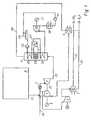
- Fig. 1shows the scheme of an emission-free power plant with CO 2 / H 2 O gas turbine and downstream steam cycle with Condensing turbine according to the prior art.
- a CO 2 / H 2 O turbo setconsisting of a compressor 1, a combustion chamber 2, a turbine 3 and a generator 8 arranged on a common shaft 8 is connected via a waste heat boiler 4 and serving as a heat sink capacitor 5 to a closed circuit ,
- the hot gases emerging from the gas turbine 3are supplied to the waste heat boiler via the hot gas path 23, and the exhaust gases cooled in the waste heat boiler 4 are fed to the condenser 5 via the waste gas path 40 behind the waste heat boiler 4.
- any portion of the water contained in the working mediumcan be condensed out with the aid of the capacitor 5.
- the resulting from the combustion of eg natural gas carbon dioxideis diverted in stationary operation of a compressor 6, brought to the pressure required for further use, further dried in the cooler 7 and liquefied, and removed from the process via line 32.
- this compression processis advantageously carried out in multiple stages with intermediate cooling and drying.
- the steam cycleincludes the Kondensationsdampfturbine 10, downstream of a condenser 30, and behind a pump 31 which supplies the condensate a feedwater tank / degasser 24.
- the feed wateris fed behind the feed water tank 24 via a pump to an economizer 26 arranged in the waste heat boiler 4 and then to the steam drum 27.
- the steam drum 27is connected to an evaporator 28, which is also arranged in the waste heat boiler, and the steam produced in the steam drum 27 is usually overheated in a superheater stage 29 and then fed to the steam turbine 10.
- the systemis equipped with the additional components shown in FIG.
- Air dampers or a differently realizedarranged in the hot gas path 23 switching member 12, the waste heat boiler 4 is switched on the inlet side of the turbine outlet to one or more auxiliary burner 13, which are supplied by one or more fans 14 with air.
- On the outlet side of the waste heat boileris connected by a further, arranged in the exhaust path 40 switching member 15 with an auxiliary chimney 16.
- This chimney resulting in the combustion chamber 13flue gases can escape.
- steamcan be generated in the waste heat boiler before the gas turbine plant 1 - 3 is put into operation.
- the condensing turbine 10can now generate the electricity that is required to operate the air separation plant 9 and to drive the gas turbine 1 - 3 via its generator 11.
- switching elementsie gas can flow both from 3 and 13 over 12 in the direction 4, or 4 of 15 in both direction 16 and in direction 5
- the generator 8 motordriven and the burner 2 with fuel and oxygen from the air separation plant 9 put into operation.
- the power of the auxiliary burners 13 and blower 14is continuously reduced until the exhaust gases of the gas turbine have reached a sufficiently high temperature.
- the circuitis closed by means of the switching elements 12 and 15.
- the systemcan be designed so that 17 ambient air is sucked in for starting the gas turbine via a further switching element.
- the closed circuitAfter completion of the start-up phase of the closed circuit initially contains a typical combustion gas mixture with high nitrogen and oxygen content. To compensate for the influx of oxygen and fuel, e.g. continuously discharged through the auxiliary chimney 16, a portion of the circulating gas. After a short time, the composition of the recycle gas approaches a stable equilibrium with the main components carbon dioxide and water and the system can be switched to completely emission-free operation.
- Such a modified power plantalso allows separate operation exclusively of the steam turbine cycle in the sense of an emergency generator. This may be necessary, for example, if the Gas turbine plant due to a failure of the air separation plant 9 must be taken out of service or the gas turbine plant must be shut down for other reasons.
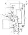
- Fig. 3shows a suitably equipped system in the version with a back pressure turbine.
- This systemadditionally includes a switching device 18, with which the partially compressed in the back pressure turbine steam to the gas turbine is passed directly to the liquefaction in the cooler 5.
- the partially expanded steamcan also be used for preheating the boiler feed water before liquefaction (obvious to the person skilled in the art and therefore not shown schematically as an additional option in FIG. 3).
- the switching device 18is brought to its normal operating position and the steam in the gas turbine with power released to ambient pressure. Since the back pressure turbine with the same fuel consumption of the auxiliary burner 13 delivers considerably less power than the condensation turbine of FIG. 2, this structure is suitable for starting air separation plant and gas turbine, but is less suitable for emergency operation.
Landscapes
- Engineering & Computer Science (AREA)
- Chemical & Material Sciences (AREA)
- Combustion & Propulsion (AREA)
- Mechanical Engineering (AREA)
- General Engineering & Computer Science (AREA)
- Engine Equipment That Uses Special Cycles (AREA)
- Control Of Turbines (AREA)
- Control Of Eletrric Generators (AREA)
Description
Translated fromGermanDie vorliegende Erfindung betrifft eine Krafterzeugungsanlage aufweisend wenigstens einen Gasturbinenkreislauf mit Abhitzekessel und wenigstens einen über den Abhitzekessel betriebenen Dampfturbinenkreislauf, wobei der Gasturbinenkreislauf halb geschlossen und im wesentlichen emissionsfrei ausgebildet ist und im wesentlichen aus einem Verdichter, einer stromab des Verdichters angeordneten Brennkammer, einer stromab der Brennkammer angeordneten Gasturbine, einem stromab der Gasturbine angeordneten Abhitzekessel, sowie wenigstens einem an die Gasturbine angekoppelten Generator besteht. Die Erfindung betrifft ausserdem Verfahren zur Inbetriebnahme und zum Betrieb einer derartigen Krafterzeugungsanlage.The present invention relates to a power generation plant comprising at least one gas turbine cycle with waste heat boiler and at least one operated via the waste heat boiler steam turbine circuit, the gas turbine circuit is semi-closed and formed substantially free of emissions and essentially from a compressor, a combustion chamber arranged downstream of the compressor, one downstream of the combustion chamber arranged gas turbine, arranged downstream of the gas turbine waste heat boiler, and at least one coupled to the gas turbine generator. The invention also relates to methods for starting up and operating such a power generation plant.
Im Rahmen der allgemeinen Bestrebungen, Kraftwerke zu entwickeln, welche eine möglichst geringe Umweltbelastung darstellen, gibt es eine Vielzahl von verschiedenen Projekten, deren Ziel die Entwicklung emissionsfreier Gasturbinenkraftwerke mit einem halb geschlossenen CO2 / H2O Kreislauf ist. Dabei wird das als Brennstoff verwendete Erdgas mit möglichst reinem Sauerstoff verbrannt. Unter diesen Umständen entstehen Verbrennungsgase, die praktisch nur aus Kohlendioxid und Wasser bestehen. Kondensiert man das Wasser aus dem Arbeitsmedium aus, so erhält man weitgehend reines Kohlendioxid, das durch Kompression verflüssigt und auf unterschiedliche Art und Weise verwendet oder entsorgt werden kann.As part of the general effort to develop power plants with the lowest possible environmental impact, there are a number of different projects aimed at developing emission-free gas turbine power plants with a semi-closed CO2 / H2 O cycle. The natural gas used as fuel is burned with the purest possible oxygen. In these circumstances, combustion gases are produced, which consist almost entirely of carbon dioxide and water. Condensing the water from the working medium, one obtains largely pure carbon dioxide, which can be liquefied by compression and used or disposed of in different ways.
Zur Nutzung der hohen Temperaturen am Turbinenaustritt wird i.d.R. ein Dampferzeuger vorgesehen, wobei der entstehende Dampf benutzt wird, um eine Kondensationsturbine anzutreiben (bottoming steam turbine). Da die Turbinenaustrittstemperatur bei üblichen Druckverhältnissen für CO2/H2O-Gemische höher ist als bei konventionellen Gasturbinen, liefert der Dampfkreislauf bei derartigen Systemen bis zu etwa 50% der Gesamtleistung.To use the high temperatures at the turbine outlet usually a steam generator is provided, the resulting steam is used to drive a condensing turbine (bottoming steam turbine). Since the turbine outlet temperature at conventional pressure ratios for CO2 / H2 O mixtures is higher than in conventional gas turbines, the steam cycle in such systems provides up to about 50% of the total power.
Alternativ kann der erzeugte Dampf in einer Gegendruckturbine vorentspannt werden (topping steam turbine), um dann vor, in oder hinter der Brennkammer mit dem Arbeitsmedium der Gasturbine vermischt zu werden. Der eingespritzte Dampf kann dann nach Durchströmen des Abhitzekessels zusammen mit dem durch die Verbrennung entstandenen Wasser auskondensiert werden. Beide Konzepte werden im Patent EP 0 731 255 B1 detaillierter beschrieben.Alternatively, the generated steam may be pre-expanded in a back pressure turbine (topping steam turbine) to then be mixed with the working fluid of the gas turbine before, in, or behind the combustor. The injected steam can then be condensed out after flowing through the waste heat boiler together with the water formed by the combustion. Both concepts are described in greater detail in patent EP 0 731 255 B1.
Weiterer Stand der Technik ist in der Schrift EP 0 939 199 A zu finden.Further prior art can be found in document EP 0 939 199 A.
Der Einsatz emissionsfreier Gasturbinenkraftwerke wird heute insbesondere im Bereich der Oel- und Gasindustrie erwogen, da das separierte Kohlendioxid dort in grossem Umfang verwendet werden kann (Enhanced Oil Recovery, EOR) und zum Teil bereits empfindliche Steuern für emittiertes Kohlendioxid gezahlt werden müssen. In der Oel- und Gasindustrie werden Kraftwerke aber häufig in einem Umfeld betrieben, in dem der Bezug von Anfahrleistung aus dem Netz schwierig oder nicht möglich ist (entlegene küstennahe Standorte, Bohrinseln, etc.). Diese Problematik wird bei emissionsfreien Kraftwerken des oben beschriebenen Typs dadurch erschwert, dass vor dem Anfahren der Turbine eine zumeist kryogen ausgeführte Luftzerlegungsanlage angefahren werden muss, die während einesThe use of emission-free gas turbine power plants is now being considered, especially in the oil and gas industry, since the separated carbon dioxide can be used there on a large scale (Enhanced Oil Recovery, EOR) and partly already sensitive taxes for emitted carbon dioxide must be paid. In the oil and gas industry, however, power plants are often operated in an environment where it is difficult or impossible to get grid power from the grid (remote offshore locations, oil rigs, etc.). These The problem is made more difficult in emission-free power plants of the type described above in that before starting up the turbine, a mostly cryogenically executed air separation plant must be started, which during a
Zeitraums von 2 bis 4 Stunden etwa 10% der Netzleistung des Kraftwerks benötigt, um einen stabilen Betriebspunkt zu erreichen.During the period of 2 to 4 hours, about 10% of the grid's power needs to reach a stable operating point.
Für einen autarken Anfahrvorgang kann bei konventionellen Gasturbinenkraftwerken Strom benutzt werden, der von den Generatoren der integrierten Dampfturbinen erzeugt wird. Als Beispiel hierfür kann eine Anordnung gemäss US Patent 5,148,668 herangezogen werden, bei welcher ein während des Betriebs aufgeladener Heisswasserspeicher den zum Anfahren benötigten Dampf liefert. Um über längere Zeit den benötigten Dampf bereitzustellen, ist in dieser Patentschrift eine Zusatzfeuerung des Heisswasserspeichers vorgesehen. Weil für emissionsfreie Kraftwerke kein schneller Start möglich ist, kann nicht auf das Konzept der Verwendung eines Heisswasserspeichers zurückgegriffen werden.For a self-sufficient starting process, conventional gas turbine power plants can use electricity generated by the generators of the integrated steam turbines. As an example of this, an arrangement according to US Pat. No. 5,148,668 can be used, in which a hot water reservoir charged during operation supplies the steam required for starting up. To provide the required steam for a long time, an additional firing of the hot water tank is provided in this patent. Because no quick startup is possible for emission-free power plants, the concept of using a hot water storage tank can not be used.
Es ist daher Aufgabe der Erfindung, eine emissionsfreie, halb geschlossene Kraftwerksanlage der obengenannten Art, das heisst gemäss dem Oberbegriff des Patentanspruchs 1, zur Verfügung zu stellen, welche Kraftwerksanlage einen Betrieb und ein Anfahren mit minimaler Anfahrleistung.It is therefore an object of the invention to provide an emission-free, semi-closed power plant of the type mentioned above, that is to say according to the preamble of claim 1, which power plant operation and starting with a minimum starting power.
Die vorliegende Erfindung löst diese Aufgabe, indem erste Mittel angeordnet werden, welche es erlauben, alternativ oder ergänzend Heissgas in den Heissgaspfad zwischen Gasturbine und Abhitzekessel einzuschleusen, und indem zweite Mittel angeordnet werden, welche es erlauben, alternativ oder ergänzend stromab des Abhitzekessels Abgas aus dem Abgaspfad auszuschleusen.The present invention solves this problem by arranging first means which allow alternatively or additionally to introduce hot gas into the hot gas path between the gas turbine and the waste heat boiler, and by arranging second means which allow, alternatively or additionally downstream of the waste heat boiler, exhaust gas from the exhaust gas Auszuschleusen exhaust path.
Diese überraschend einfache Modifikation des Gasturbinenkreislaufes erlaubt die Beheizung des Abhitzekessels bei stillstehender oder noch nicht (oder auch nicht mehr) genügend leistungsfähiger Turbogruppe, derart, dass der Dampfturbinenkreislauf energieerzeugend respektive insbesondere stromerzeugend betrieben werden kann. Mit anderen Worten wird der im normalen Betrieb von einem Abgasgemisch der Gasturbinenanlage durchströmte Abhitzekessel als hilfsbefeuerter Dampferzeuger betrieben. Die Generatoren der mit dem so erzeugten Dampf beaufschlagten Dampfturbinen erzeugen bei entsprechender Auslegung der Hilfsbefeuerung genügend Strom um sowohl eine ggf. für die Versorgung mit reinem Sauerstoff vorhandene Luftzerlegungsanlage als auch die Gasturbine anfahren zu können. Die Modifikation erlaubt es ausserdem, den Dampfturbinenkreislauf allein stromerzeugend zu betreiben, und die Anlage kann somit auch die Funktion eines Notstromaggregates übernehmen, was beispielsweise während eventueller Ausfallzeiten von Luftzerlegungsanlage und/oder Gasturbine notwendig werden kann. Üblicherweise wird dabei das aus dem Abgaspfad ausgeschleuste Abgas über einen Hilfskamin abgeführt.This surprisingly simple modification of the gas turbine cycle allows the heating of the waste heat boiler at standstill or not yet (or no longer) sufficiently powerful turbo group, such that the Steam turbine cycle energy generating respectively in particular can be operated generating electricity. In other words, the waste heat boiler through which an exhaust gas mixture of the gas turbine plant flows during normal operation is operated as a supplementary steam generator. The generators of the steam turbines acted upon by the steam generated with appropriate design of the auxiliary control sufficient power to both an optionally available for the supply of pure oxygen air separation plant and the gas turbine can start. The modification also makes it possible to operate the steam turbine cycle alone generating electricity, and the system can thus also take over the function of an emergency generator, which may be necessary, for example, during any downtime of air separation plant and / or gas turbine. Usually, the exhaust gas discharged from the exhaust path is discharged via an auxiliary chimney.
Gemäss einer ersten, besonders einfachen und bevorzugten Ausführungsform der Erfindung handelt es sich bei den ersten und zweiten Mitteln um Umschaltorgane, welche das Ein- respektive Ausschleusen insbesondere über das Umstellen von Luftklappen erlauben.According to a first, particularly simple and preferred embodiment of the invention, the first and second means are changeover devices which allow the insertion or removal, in particular, via the changeover of air dampers.
Gemäss einer weiteren Ausführungsform der Erfindung wird das zusätzliche, alternativ oder ergänzend in den Heissgaspfad einzuschleusende Heissgas von einem oder mehreren Hilfsbrennern zur Verfügung gestellt, welche bevorzugt über ein Gebläse mit Frischluft versorgt werden. Grundsätzlich ist es aber auch möglich, das Heissgas auf andere Art und Weise zur Verfügung zu stellen, beispielsweise über Wärmetauscher, Katalysatoren, etc..According to a further embodiment of the invention, the additional, alternatively or additionally introduced into the hot gas path hot gas is provided by one or more auxiliary burners, which are preferably supplied via a blower with fresh air. In principle, however, it is also possible to provide the hot gas in another way, for example via heat exchangers, catalysts, etc ..
Vorteilhafterweise wird die erfindungsgemässe Krafterzeugungsanlage als CO2/H2O-Anlage betrieben, das heisst es handelt sich dabei um einen CO2/H2O-Gasturbinenkreislauf, bei welchem entstehendes CO2 und H2O über entsprechende Mittel zur Kompression und/oder Mittel zur Kühlung aus dem Gasturbinenkreislauf insbesondere bevorzugt unmittelbar stromab des Verdichters abzweigend und insbesondere in fester und/oder flüssiger Form entfernt wird, wobei der Gasturbinenkreislauf insbesondere über eine Luftzerlegungsanlage mit weitgehend reinem Sauerstoff versorgt wird. Dabei kann es die Luftzerlegungsanlage kryogen oder auf Membranverfahren basierend ausgebildet sein.Advantageously, the inventive power generation plant is operated as CO2 / H2 O plant, that is, it is a CO2 / H2 O gas turbine cycle, in which resulting CO2 and H2 O via appropriate means for compression and / or Means for cooling from the gas turbine cycle in particular preferably immediately downstream of the compressor branches off and in particular in solid and / or liquid form is removed, the gas turbine cycle is supplied in particular via an air separation plant with substantially pure oxygen. It can be the Air separation unit cryogenic or membrane-based based formed.
Gemäss einer anderen bevorzugten Ausführungsform der Erfindung ist der Dampfturbinenkreislauf im wesentlichen geschlossen ausgebildet und weist wenigstens eine Dampfturbine und wenigstens einen daran angekoppelten Generator auf. Dabei kann der Dampfturbinenkreislauf unter alleiniger Verwendung von über die ersten Mittel eingeschleustem Heissgas bei gleichzeitiger Abführung der Abgase über die zweiten Mittel derart betrieben werden, dass der Generator genügend Energie erzeugt, um die Gasturbinenanlage und eine ggf. vorhandene Luftzerlegungsanlage in Betrieb zu nehmen, respektive um bei Ausfall der Gasturbinenanlage als Notstromaggregat zu dienen. Um den besonderen Bedürfnissen beim Anfahren respektive beim Betrieb als Notstromaggregat gerecht zu werden, kann ausserdem vorzugsweise ein weiteres Umschaltorgan stromauf des Verdichters angeordnet werden, über welches Umgebungsluft angesaugt werden kann.According to another preferred embodiment of the invention, the steam turbine cycle is formed substantially closed and has at least one steam turbine and at least one generator coupled thereto. In this case, the steam turbine cycle with the sole use of introduced via the first means hot gas with simultaneous removal of the exhaust gases via the second means can be operated so that the generator generates enough energy to take the gas turbine plant and any existing air separation plant in operation, respectively to serve as emergency generator in case of failure of the gas turbine plant. In order to meet the special needs when starting respectively when operating as an emergency generator, may also preferably another switching device upstream of the compressor can be arranged, via which ambient air can be sucked.
Je nach Bedürfnissen kann die im Dampfturbinenkreislauf angeordnete Dampfturbine als Kondensationsturbine ausgestaltet sein oder als Gegendruckturbine, deren teilentspannter Abdampf in der Gasturbine nach Einspritzung in das Kreislaufmedium vor, in, und/oder nach der Brennkammer unter Leistungsabgabe bis auf Umgebungsdruck entspannt wird, wobei insbesondere ein Umschaltorgan vorgesehen ist, mit welchem der Abdampf an der Gasturbine vorbei direkt zur Verflüssigung in einen im Gasturbinenkreislauf angeordneten Kühler geleitet werden kann.Depending on requirements, arranged in the steam turbine cycle steam turbine can be designed as a condensation turbine or as a backpressure turbine whose teilentspannte Abdampf in the gas turbine after injection into the circulation medium before, in, and / or relaxed after the combustion chamber under power output to ambient pressure, in particular a switching is provided, with which the exhaust steam can be passed to the gas turbine directly for liquefaction in a arranged in the gas turbine cycle cooler.
Weitere bevorzugte Ausführungsformen der erfindungsgemässen Kraftwerksanlage sind in den abhängigen Patentansprüchen beschrieben.Further preferred embodiments of the power plant according to the invention are described in the dependent claims.
Die vorliegende Erfindung betrifft ausserdem ein Verfahren zur Inbetriebnahme einer Krafterzeugungsanlage wie sie oben beschrieben ist, welches dadurch gekennzeichnet ist, dass zunächst in einer ersten Phase der Dampfturbinenkreislauf mit über die ersten Mittel eingeschleustem Heissgas bei gleichzeitiger wenigstens teilweiser Ausschleusung der Abgase über die zweiten Mittel in Betrieb genommen wird, dann in einer zweiten Phase ein im Dampfturbinenkreislauf angeordneter Generator den Generator des Gasturbinenkreislaufs motorisch mit Strom zum Anfahren der Turbogruppe antreibt, wobei der Verdichter über eine stromauf angeordnete Luftklappe und/oder über die in beide Richtungen geöffneten zweiten Mittel Frischluft oder ein Verbrennungsgasgemisch ansaugt, durch die Brennkammer fördert, in welcher ggf. unter zusätzlicher Zufuhr von weitgehend reinem Sauerstoff Brennstoff verfeuert wird, sodass die Gasturbine den motorisch angetriebenen Generator zu unterstützen beginnt, und schliesslich als alleiniger Antrieb dient, wobei die heißen Abgase der Gasturbine sukzessive und am Ende vollständig die Dampferzeugung im Abhitzekessel übernehmen. Die Trennung in einzelne Phasen ist dabei nicht absolut strikt zu sehen, eine entsprechende optimale Führung des Anfahrprozesses mit teilweise überlappenden Abschnitten kann vom Fachmann ermittelt werden.The present invention also relates to a method for starting up a power generation plant as described above, which is characterized in that first in a first phase of the steam turbine cycle with introduced via the first means hot gas with simultaneous at least partial discharge of the exhaust gases via the second means in operation is taken, then in a second phase an im Steam Turbine Circuit generator arranged the generator of the gas turbine cycle motor with power to start the turbo group drives, the compressor via an upstream air damper and / or via the open in both directions second means fresh air or a combustion gas mixture sucks, promotes through the combustion chamber, in which possibly fuel is fired with additional supply of largely pure oxygen fuel, so that the gas turbine begins to support the motor-driven generator, and finally serves as the sole drive, the hot exhaust gases of the gas turbine successively and at the end take over the steam generation in the waste heat boiler. The separation into individual phases is not absolutely strict, a corresponding optimal guidance of the starting process with partially overlapping sections can be determined by a person skilled in the art.
Des Weiteren betrifft die vorliegende Erfindung ein Verfahren zur Inbetriebnahme einer Krafterzeugungsanlage wie sie oben beschrieben ist, gekennzeichnet dadurch, dass zunächst in einer ersten Phase der Dampfturbinenkreislauf mit über die ersten Mittel eingeschleustem Heissgas bei gleichzeitiger wenigstens teilweiser Ausschleusung der Abgase über die zweiten Mittel in Betrieb genommen wird, dass nach erfolgtem Selbstlauf der über eine stromauf des Verdichters angeordnete Luftklappe mit Luft als Ersatzmedium betriebenen Turbogruppe in einer zweiten Phase über die ersten und zweiten Mittel und die Luftklappe der Gasturbinenkreislauf geschlossen und der Brennkammer weitgehend reiner Sauerstoff als Oxidationsmittel zugeführt wird, wobei kontinuierlich Gas aus dem Kreislauf ausgeschleust wird, um die Zufuhr von Sauerstoff und Brennstoff zu kompensieren, und wobei sich die Zusammensetzung des umlaufenden Gases sukzessive einem Gleichgewicht nähert, in dem mit der Separation und Verflüssigung der Verbrennungsprodukte begonnen werden kann. Das Gleichgewicht ist dabei dann erreicht, wenn das Verbrennungsgasgemisch im wesentlichen nur noch aus CO2 und H2O besteht und kein Stickstoff, Sauerstoff o.ä., die den Kondensationsprozess des CO2 stören könnten, mehr vorhanden sind. Dabei kann der nach der ersten Phase über den Generator verfügbare Strom wenigstens teilweise zum Betrieb der Luftzerlegungsanlage und damit zur Bereitstellung von weitgehend reinem Sauerstoff für den Verbrennungsprozess in der Brennkammer verwendet werden.Furthermore, the present invention relates to a method for starting up a power plant as described above, characterized in that initially taken in a first phase of the steam turbine cycle with introduced via the first means hot gas with simultaneous at least partial discharge of the exhaust gases via the second means in operation is that after completion of the self-running arranged over an upstream of the compressor damper with air as a replacement medium operated turbo group closed in a second phase on the first and second means and the damper of Gasturbinenkreislauf and the combustion chamber largely pure oxygen is supplied as the oxidant, wherein continuously gas is discharged from the circuit to compensate for the supply of oxygen and fuel, and wherein the composition of the circulating gas successively approaches an equilibrium, in which with the separation and Verfl can begin ssigung the combustion products. The equilibrium is achieved when the combustion gas mixture consists essentially only of CO2 and H2 O and no nitrogen, oxygen or the like, which could interfere with the condensation process of CO2 , are more present. In this case, the power available via the generator after the first phase can at least partially be used to operate the Air separation plant and thus be used to provide largely pure oxygen for the combustion process in the combustion chamber.
Die erfindungsgemässe Kraftwerksanlage kann ausserdem derart gefahren werden, dass bei nicht betriebenem Gasturbinenkreislauf nur der Dampfturbinenkreislauf über die Einschleusung von Heissluft mit den ersten Mitteln und über die Ausschleusung von Abgasen mit den zweiten Mitteln betrieben wird, und dass so der im Dampfturbinenkreislauf angeordnete Generator Strom insbesondere im Sinne eines Notstromaggregates zur Verfügung stellt.The inventive power plant can also be driven such that when not operated gas turbine cycle only the steam turbine cycle is operated via the introduction of hot air with the first means and via the discharge of exhaust gases with the second means, and that so arranged in the steam turbine generator current especially in Provides sense of an emergency generator.
Weitere bevorzugte Ausführungsformen der erfindungsgemässen Verfahren sind in den abhängigen Patentansprüchen beschrieben.Further preferred embodiments of the inventive method are described in the dependent claims.
Die Erfindung soll nachfolgend anhand von Ausführungsbeispielen im Zusammenhang mit den Figuren näher erläutert werden. Es zeigen:
- Fig. 1
- ein Schema eines emissionsfreien Gasturbinenkraftwerkes nach dem Stand der Technik;
- Fig. 2
- ein Schema eines erfindungsgemässen emissionsfreien Gasturbinenkraftwerkes mit Kondensationsturbine ; und
- Fig. 3
- ein Schema eines erfindungsgemässen emissionsfreien Gasturbinenkraftwerkes mit Gegendruckturbine.
- Fig. 1
- a schematic of an emission-free gas turbine power plant according to the prior art;
- Fig. 2
- a diagram of an inventive emission-free gas turbine power plant with a condensation turbine; and
- Fig. 3
- a diagram of an inventive emission-free gas turbine power plant with back pressure turbine.
Fig. 1 zeigt das Schema eines emissionsfreien Kraftwerks mit CO2/H2O-Gasturbine und nachgeschaltetem Wasserdampfkreislauf mit Kondensationsturbine nach dem Stand der Technik. Ein CO2/H2O-Turbosatz, bestehend aus einem Verdichter 1, einer Brennkammer 2, einer Turbine 3 und einem auf einer gemeinsamen Welle 22 angeordneten Generator 8 ist über einen Abhitzekessel 4 und einen als Wärmesenke dienenden Kondensator 5 zu einem geschlossenen Kreislauf verschaltet. Die aus der Gasturbine 3 austretenden Heissgase werden über den Heissgaspfad 23 dem Abhitzekessel zugeführt, und die im Abhitzekessel 4 abgekühlten Abgase werden hinter dem Abhitzekessel 4 über den Abgaspfad 40 dem Kondensator 5 zugeführt. Bis zu einer durch die Kühlwassertemperatur vorgegebenen Grenze kann mit Hilfe des Kondensators 5 ein beliebiger Anteil des im Arbeitsmedium enthaltenen Wassers auskondensiert werden. Das durch die Verbrennung von z.B. Erdgas entstehende Kohlendioxid wird im stationären Betrieb von einem Kompressor 6 abgezweigt, auf den für die weitere Verwendung benötigten Druck gebracht, im Kühler 7 weiter getrocknet und verflüssigt, und aus dem Prozess über die Leitung 32 entfernt. In der Praxis wird dieser Verdichtungsprozess vorteilhaft mehrstufig mit Zwischenkühlung und - trocknung ausgeführt. Für die Oxidation des Brennstoffs in der Brennkammer 2 wird technisch reiner Sauerstoff eingesetzt; der in einer hier nicht weiter beschriebenen und nur schematisch dargestellten Luftzerlegungsanlage 9 gewonnen wird.Fig. 1 shows the scheme of an emission-free power plant with CO2 / H2 O gas turbine and downstream steam cycle with Condensing turbine according to the prior art. A CO2 / H2 O turbo set, consisting of a compressor 1, a
Der im Abhitzekessel gewonnene Wasserdampf beaufschlagt im Rahmen einer üblichen Kreislaufschaltung eine Kondensationsdampfturbine 10 mit Generator 11. Der Dampfkreislauf umfasst dabei die Kondensationsdampfturbine 10, stromab davon einen Kondensator 30, und dahinter eine Pumpe 31, welche das Kondensat einem Speisewasserbehälter/Entgaser 24 zuführt. Das Speisewasser wird hinter dem Speisewasserbehälter 24 über eine Pumpe einem im Abhitzekessel 4 angeordneten Economizer 26 und anschliessend der Dampftrommel 27 zugeführt. Die Dampftrommel 27 ist mit einem Verdampfer 28, welcher ebenfalls im Abhitzekessel angeordnet ist, verbunden, und der in der Dampftrommel 27 produzierte Dampf wird üblicherweise in einer Überhitzerstufe 29 überhitzt und anschliessend der Dampfturbine 10 zugeführt.The steam recovered in the waste heat boiler applied as part of a conventional circulation a
Um dieses System nun weitgehend autark anfahren zu können, wird die Anlage mit den in Fig. 2 dargestellten zusätzlichen Komponenten ausgerüstet. Durch Luftklappen oder ein anders realisiertes, im Heissgaspfad 23 angeordnetes Umschaltorgan 12 wird der Abhitzekessel 4 eintrittseitig vom Turbinenaustritt auf einen oder mehrere Hilfsbrenner 13 umgeschaltet, die von einem oder mehreren Gebläsen 14 mit Luft versorgt werden. Austrittseitig wird der Abhitzekessel durch ein weiteres, im Abgaspfad 40 angeordnetes Umschaltorgan 15 mit einem Hilfskamin 16 verbunden. Ueber diesen Kamin können die in der Brennkammer 13 entstandenen Rauchgase entweichen. Auf diese Weise kann im Abhitzekessel Dampf erzeugt werden, bevor die Gasturbinenanlage 1 - 3 in Betrieb genommen wird. Die Kondensationsturbine 10 kann nun über ihren Generator 11 den Strom erzeugen, der benötigt wird, um die Luftzerlegungsanlage 9 zu betreiben und die Gasturbine 1 - 3 anzufahren.In order to be able to approach this system largely autonomously, the system is equipped with the additional components shown in FIG. By Air dampers or a differently realized, arranged in the
Zum Anfahren der Gasturbine wird bei beidseitig geöffneten Umschaltorganen 12 und 15 (d.h. Gas kann sowohl von 3 als auch von 13 über 12 in Richtung 4 strömen, bzw. von 4 über 15 sowohl in Richtung 16 als auch in Richtung 5) der Generator 8 motorisch angetrieben und der Brenner 2 mit Brennstoff und Sauerstoff aus der Luftzerlegungsanlage 9 in Betrieb genommen. Die Leistung der Hilfsbrenner 13 und Gebläse 14 wird kontinuierlich reduziert, bis die Abgase der Gasturbine eine ausreichend hohe Temperatur erreicht haben. Dann wird der Kreislauf mit Hilfe der Umschaltorgane 12 und 15 geschlossen. Alternativ kann die Anlage so ausgeführt werden, dass für das Anfahren der Gasturbine über ein weiteres Umschaltorgan 17 Umgebungsluft angesogen wird.To start the
Nach Beendigung der Anfahrphase enthält der geschlossene Kreislauf zunächst ein typisches Verbrennungsgasgemisch mit hohem Stickstoff- und Sauerstoffgehalt. Um den Zustrom an Sauerstoff und Brennstoff auszugleichen, wird z.B. über den Hilfskamin 16 kontinuierlich ein Teil des im Kreislauf befindlichen Gases ausgeschleust. Nach kurzer Zeit nähert sich so die Zusammensetzung des Kreislaufgases einem stabilen Gleichgewicht mit den Hauptkomponenten Kohlendioxid und Wasser und die Anlage kann auf vollständig emissionsfreien Betrieb umgeschaltet werden.After completion of the start-up phase of the closed circuit initially contains a typical combustion gas mixture with high nitrogen and oxygen content. To compensate for the influx of oxygen and fuel, e.g. continuously discharged through the
Eine derartige modifizierte Kraftwerksanlage erlaubt ausserdem einen separaten Betrieb ausschliesslich des Dampfturbinenkreislaufes im Sinne eines Notstromaggregates. Dies kann beispielsweise notwendig werden, wenn die Gasturbinenanlage auf Grund eines Ausfalls der Luftzerlegungsanlage 9 ausser Betrieb genommen werden muss oder die Gasturbinenanlage aus anderen Gründen stillgelegt werden muss.Such a modified power plant also allows separate operation exclusively of the steam turbine cycle in the sense of an emergency generator. This may be necessary, for example, if the Gas turbine plant due to a failure of the
Fig. 3 zeigt eine sinngemäss ausgerüstete Anlage in der Ausführung mit einer Gegendruckturbine. Diese Anlage enthält zusätzlich ein Umschaltorgan 18, mit dem der in der Gegendruckturbine teilentspannte Dampf an der Gasturbine vorbei direkt zur Verflüssigung in den Kühler 5 geleitet wird. Alternativ kann der teilentspannte Dampf vor der Verflüssigung auch zum Vorwärmen des Kesselspeisewassers genutzt werden (dem Fachmann offensichtlich und daher in Fig. 3 nicht als zusätzliche Option schematisch dargestellt). Wird die Gasturbine 1-3 angefahren, so wird das Umschaltorgan 18 in seine normale Betriebsposition gebracht und der Dampf in der Gasturbine unter Leistungsabgabe bis auf Umgebungsdruck entspannt. Da die Gegendruckturbine bei gleichem Brennstoffverbrauch der Hilfsbrenner 13 erheblich weniger Leistung liefert als die Kondensationsturbine nach Fig. 2, eignet sich dieser Aufbau zum Anfahren von Luftzerlegungsanlage und Gasturbine, ist aber weniger für den Notfallbetrieb geeignet.Fig. 3 shows a suitably equipped system in the version with a back pressure turbine. This system additionally includes a
Für den technisch versierten Fachmann ist offensichtlich, dass sich das oben beschriebene Verfahren nicht nur auf die beiden beschriebenen Prozesse anwenden lässt, sondern ebenso auf eine Vielzahl denkbarer Prozessvarianten, die dadurch gekennzeichnet sind, dass eine Gas- und eine Dampfturbine so kombiniert werden, dass das Arbeitsmedium der Gasturbine in einem zumindest teilweise geschlossenen Kreislauf mit oder ohne Kondensation gefahren wird, dem Kreislauf weitgehend reiner Sauerstoff als Oxydationsmittel zugeführt wird, und der benötigte Dampf im normalen Betrieb durch Nutzung der Abwärme der Gasturbine erzeugt wird.It is obvious to the person skilled in the art that the method described above can be applied not only to the two processes described, but also to a multiplicity of conceivable process variants, which are characterized in that a gas turbine and a steam turbine are combined in such a way that the Working medium of the gas turbine is driven in an at least partially closed circuit with or without condensation, the circuit largely pure oxygen is supplied as oxidant, and the steam required is generated in normal operation by using the waste heat of the gas turbine.
- 11
- Verdichtercompressor
- 22
- Brennkammercombustion chamber
- 33
- Turbineturbine
- 44
- Abhitzekesselwaste heat boiler
- 55
- Kühler, KondensatorCooler, condenser
- 66
- Kompressorcompressor
- 77
- Kühlercooler
- 88th
- Generatorgenerator
- 99
- LuftzerlegungsanlageAir separation plant
- 1010
- KondensationsdampfturbineCondensing steam turbine
- 1111
- Generatorgenerator
- 1212
- Umschaltorganchangeover
- 1313
- Hilfsbrennerauxiliary burner
- 1414
- Gebläsefan
- 1515
- Umschaltorganchangeover
- 1616
- Hilfskaminauxiliary fire
- 1717
- Umschaltorganchangeover
- 1818
- Umschaltorganchangeover
- 1919
- GegendruckturbineBack pressure turbine
- 2020
- Brennstoffzufuhrfuel supply
- 2121
- Sauerstoffzufuhroxygen supply
- 2222
- Wellewave
- 2323
- Leitung zum Abhitzekessel, HeissgaspfadLine to the waste heat boiler, hot gas path
- 2424
- SpeisewasserbehälterFeedwater tank
- 2525
- Pumpepump
- 2626
- Economizereconomizer
- 2727
- Dampftrommelsteam drum
- 2828
- VerdampferEvaporator
- 2929
- Überhitzersuperheater
- 3030
- Kondensatorcapacitor
- 3131
- Pumpepump
- 3232
- Abführleitung für KohlendioxidDischarge line for carbon dioxide
- 3333
- Abführleitung für WasserDrainage pipe for water
- 3434
- FrischluftzufuhrFresh air
- 3535
- Brennstoffzufuhrfuel supply
- 3636
- variabler Heissgaspfadvariable hot gas path
- 3737
- variabler Abgaspfadvariable exhaust path
- 3838
- variabler Dampfpfadvariable steam path
- 3939
- Frischluftzufuhr, FrischluftFresh air supply, fresh air
- 4040
- Leitung zum Kondensator 5, AbgaspfadLine to the
condenser 5, exhaust path
Claims (15)
- Power generation plant having at least one gas turbine cycle with heat-recovery boiler (4) and at least one steam turbine cycle operated via the heat-recovery boiler (4), the gas turbine cycle being designed to be semi-closed and essentially free of emissions and essentially comprising a compressor (1), a combustion chamber (2) arranged downstream of the compressor (1), a gas turbine (3) arranged downstream of the combustion chamber (2), a heat-recovery boiler (4) arranged downstream of the gas turbine (3), and at least one generator (8) coupled to the gas turbine (3),characterized in that first means (12) are arranged which alternatively or additionally allow hot gas to be fed into the hot-gas path (23) between gas turbine (3) and heat-recovery boiler (4), andin that second means (15) are arranged which alternatively or additionally allow exhaust gas to be expelled from the exhaust-gas path (40) downstream of the heat-recovery boiler (4).
- Power generation plant according to Claim 1,characterized in that the first and second means (12, 15) are switch-over members which allow the feeding-in or expelling in particular by resetting air flaps.
- Power generation plant according to either of the preceding claims,characterized in that the additional hot gas, to be alternatively or additionally fed into the hot-gas path (23), is provided by one or more auxiliary burners (13) which are preferably supplied with fresh air (34) via a blower (14).
- Power generation plant according to one of the preceding claims,characterized in that a CO2/H2O gas turbine cycle is involved in which CO2 and H2O produced, via corresponding means for compression (6) and/or means for cooling (7), are removed from the gas turbine cycle, in particular preferably in such a way as to branch off directly downstream of the compressor (1), and in particular in a liquid and/or supercritical form, andin that the gas turbine cycle is supplied with largely pure oxygen in particular via an air separation plant (9).
- Power generation plant according to Claim 4,characterized in that the air separation plant (9) is a cryogenic plant or a plant based on a diaphragm process.
- Power generation plant according to one of the preceding claims,characterized in that the steam turbine cycle is of essentially closed design and has at least one steam turbine (10, 19) and at least one generator (11) coupled thereto, andin that the steam turbine cycle, with the use solely of hot gas fed in via the first means, while gas is simultaneously expelled via the second means, can be operated in such a way that the generator (11) generates sufficient energy in order to put the gas turbine plant (1-3) and an air separation plant (9) possibly present into operation, or respectively in order to serve as emergency generating unit in the event of a failure of the gas turbine plant (1-3).
- Power generation plant according to Claim 6,characterized in that, for starting up the gas turbine, a further switch-over member (17), via which ambient air (39) can be drawn in, is arranged upstream of the compressor (1).
- Power generation plant according to one of the preceding claims,characterized in that the steam turbine arranged in the steam turbine cycle is a bottoming steam turbine (10).
- Power generation plant according to one of the preceding claims,characterized in that the steam turbine cycle comprises a topping steam turbine (19), the partly expanded exhaust steam of which, after injection into the cycle medium upstream of, in and/or downstream of the combustion chamber (2), is expanded to ambient pressure in the gas turbine (3), with power being delivered, in particular a switch-over member (18) being provided with which the exhaust steam can be directed past the gas turbine directly for liquefaction into a cooler (5) arranged in the gas turbine cycle.
- Method of starting up a power generation plant according to one of Claims 1 to 9,characterized in that, first of all, in a first phase, the steam turbine cycle is put into operation with hot gas fed in via the first means (12), while at the same time the exhaust gases are at least partly expelled via the second means (15), then, in a second phase, the generator (8) of the gas turbine cycle is motor-driven with current by a generator (11) arranged in the steam turbine cycle in order to start up the turboset (1, 3), the compressor (1), via an air flap (17) arranged upstream and/or via the second means (15) opened in both directions, drawing in fresh air or a combustion-gas mixture and delivering it through the combustion chamber (2), in which, possibly with additional feeding of largely pure oxygen, fuel is fired, so that the turbine (3) starts to assist the motor-driven generator (8) and finally serves as sole drive, the hot exhaust gases of the gas turbine (3) progressively taking over the steam generation in the heat-recovery boiler (4) and completely taking over the steam generation in the heat-recovery boiler (4) at the end.
- Method of starting up a power generation plant according to one of Claims 1 to 9,characterized in that, first of all, in a first phase, the steam turbine cycle is put into operation with hot gas fed in via the first means (12), while at the same time the exhaust gases are at least partly expelled via the second means (15),in that, after the turboset (1-3, 8), operated with air as substitute medium via an air flap (17) arranged upstream of the compressor (1), is running in a self-sustaining manner, in a second phase, the gas turbine cycle is closed via the first and second means (12, 15) and the air flap (17), and largely pure oxygen is fed as an oxidizing agent to the combustion chamber (3), gas being continuously expelled from the cycle in order to compensate for the feed of oxygen and fuel, and the composition of the circulating gas progressively approaching an equilibrium, in which the separation and liquefaction of the combustion products can be started.
- Method according to Claim 11,characterized in that the gas turbine cycle is a CO2/H2O gas turbine cycle, andin that the separation and liquefaction of excess carbon dioxide can be started by the carbon dioxide, in a compressor (6), being brought to the pressure required for further use and being further dried and liquefied in a cooler (7).
- Method according to one of Claims 10 to 12,characterized in that the current available after the first phase via the generator (11) is at least partly used for operating the air separation plant (9) and thus for providing largely pure oxygen for the combustion process in the combustion chamber (2).
- Method according to one of Claims 10 to 13,characterized in that, during or after the first phase, a large proportion of the start-up output is made available in the form of heat by means of the auxiliary burners (13).
- Method of operating a power generation plant according to one of Claims 1 to 9,characterized in that, when the gas turbine cycle is not operating, only the steam turbine cycle is operated via the feeding-in of hot air with the first means (12) and via the expelling of exhaust gases with the second means (15), andin that the generator (11) arranged in the steam turbine cycle thus provides current in particular in the sense of an emergency generating unit.
Applications Claiming Priority (3)
| Application Number | Priority Date | Filing Date | Title |
|---|---|---|---|
| CH18092001 | 2001-10-01 | ||
| CH180901 | 2001-10-01 | ||
| PCT/IB2002/004006WO2003029618A1 (en) | 2001-10-01 | 2002-09-30 | Method and device for the starting of emission-free gas turbine power stations |
Publications (2)
| Publication Number | Publication Date |
|---|---|
| EP1432889A1 EP1432889A1 (en) | 2004-06-30 |
| EP1432889B1true EP1432889B1 (en) | 2006-07-12 |
Family
ID=4566355
Family Applications (1)
| Application Number | Title | Priority Date | Filing Date |
|---|---|---|---|
| EP02762728AExpired - LifetimeEP1432889B1 (en) | 2001-10-01 | 2002-09-30 | Method and device for the starting of emission-free gas turbine power stations |
Country Status (5)
| Country | Link |
|---|---|
| US (1) | US6945052B2 (en) |
| EP (1) | EP1432889B1 (en) |
| DE (1) | DE50207526D1 (en) |
| NO (1) | NO322002B1 (en) |
| WO (1) | WO2003029618A1 (en) |
Cited By (1)
| Publication number | Priority date | Publication date | Assignee | Title |
|---|---|---|---|---|
| DE102013223661A1 (en)* | 2013-11-20 | 2015-05-21 | Siemens Aktiengesellschaft | Method and device for energy conversion |
Families Citing this family (118)
| Publication number | Priority date | Publication date | Assignee | Title |
|---|---|---|---|---|
| EP1432889B1 (en) | 2001-10-01 | 2006-07-12 | Alstom Technology Ltd | Method and device for the starting of emission-free gas turbine power stations |
| US7107774B2 (en)* | 2003-08-12 | 2006-09-19 | Washington Group International, Inc. | Method and apparatus for combined cycle power plant operation |
| US7414331B2 (en)* | 2004-03-31 | 2008-08-19 | General Electric Company | Power converter system and method |
| DE102005015151A1 (en) | 2005-03-31 | 2006-10-26 | Alstom Technology Ltd. | Gas turbine system for power station, has control device to control volume flow and/or temperature of combustion exhaust gas, such that fresh gas-exhaust gas-mixture entering into compressor of turbo group has preset reference temperature |
| CA2543098A1 (en)* | 2005-04-18 | 2006-10-18 | Alstom Technology Ltd. | Turbo set with starting device |
| CH697636B1 (en)* | 2005-04-18 | 2008-12-31 | Alstom Technology Ltd | Turbine group with starting device. |
| US20070130952A1 (en)* | 2005-12-08 | 2007-06-14 | Siemens Power Generation, Inc. | Exhaust heat augmentation in a combined cycle power plant |
| US20080078178A1 (en)* | 2006-07-20 | 2008-04-03 | Jay Johnson | Use of exhaust in thermal devices |
| FR2911912B1 (en)* | 2007-01-25 | 2009-03-06 | Air Liquide | METHOD FOR ENERGETIC OPTIMIZATION OF AN ENERGY PRODUCTION SITE AND WATER VAPOR. |
| WO2008155242A1 (en) | 2007-06-19 | 2008-12-24 | Alstom Technology Ltd | Gas turbine system having exhaust gas recirculation |
| US20090155889A1 (en)* | 2007-12-13 | 2009-06-18 | Alstom Technology Ltd | System and method for regeneration of an absorbent solution |
| EP2276559A4 (en) | 2008-03-28 | 2017-10-18 | Exxonmobil Upstream Research Company | Low emission power generation and hydrocarbon recovery systems and methods |
| WO2009120779A2 (en) | 2008-03-28 | 2009-10-01 | Exxonmobil Upstream Research Company | Low emission power generation and hydrocarbon recovery systems and methods |
| US8091369B2 (en)* | 2008-07-11 | 2012-01-10 | Air Products And Chemicals, Inc. | Method and apparatus for generating electrical power |
| US20100024433A1 (en)* | 2008-07-30 | 2010-02-04 | John Frederick Ackermann | System and method of operating a gas turbine engine with an alternative working fluid |
| US20100044643A1 (en)* | 2008-08-22 | 2010-02-25 | Hunton Energy Holdings, LLC | Low NOx Gasification Startup System |
| US9297306B2 (en)* | 2008-09-11 | 2016-03-29 | General Electric Company | Exhaust gas recirculation system, turbomachine system having the exhaust gas recirculation system and exhaust gas recirculation control method |
| EA026915B1 (en) | 2008-10-14 | 2017-05-31 | Эксонмобил Апстрим Рисерч Компани | Methods and systems for controlling the products of combustion |
| EP2246532A1 (en)* | 2008-12-24 | 2010-11-03 | Alstom Technology Ltd | Power plant with CO2 capture |
| US8763404B2 (en) | 2008-12-31 | 2014-07-01 | Rolls-Royce Corporation | Systems, apparatuses, and methods of harnessing thermal energy of gas turbine engines |
| US8596075B2 (en) | 2009-02-26 | 2013-12-03 | Palmer Labs, Llc | System and method for high efficiency power generation using a carbon dioxide circulating working fluid |
| ES2733083T3 (en) | 2009-02-26 | 2019-11-27 | 8 Rivers Capital Llc | Apparatus and method for burning a fuel at high pressure and high temperature, and associated system and device |
| US10018115B2 (en) | 2009-02-26 | 2018-07-10 | 8 Rivers Capital, Llc | System and method for high efficiency power generation using a carbon dioxide circulating working fluid |
| US20100229523A1 (en)* | 2009-03-16 | 2010-09-16 | General Electric Company | Continuous combined cycle operation power plant and method |
| US8387355B2 (en)* | 2009-07-15 | 2013-03-05 | Ormat Technologies Inc. | Gas turbine exhaust gas cooling system |
| US7954478B1 (en)* | 2009-07-27 | 2011-06-07 | Michael Moses Schechter | Airless engine |
| EP2499332B1 (en) | 2009-11-12 | 2017-05-24 | Exxonmobil Upstream Research Company | Integrated system for power generation and method for low emission hydrocarbon recovery with power generation |
| EP2335804B1 (en) | 2009-12-04 | 2014-09-10 | Alstom Technology Ltd | A method and a device for cleaning a carbon dioxide rich flue gas |
| DE102010005695A1 (en)* | 2010-01-25 | 2011-07-28 | Airbus Operations GmbH, 21129 | Autarchic monument in the aircraft pressurized cabin with decentralized fuel supply and efficient energy conversion |
| GB201003436D0 (en)* | 2010-03-02 | 2010-04-14 | Rolls Royce Plc | Power generation assembly and method |
| US20110265445A1 (en)* | 2010-04-30 | 2011-11-03 | General Electric Company | Method for Reducing CO2 Emissions in a Combustion Stream and Industrial Plants Utilizing the Same |
| TWI564475B (en) | 2010-07-02 | 2017-01-01 | 艾克頌美孚上游研究公司 | Low emission triple-cycle power generation systems and methods |
| CA2801492C (en) | 2010-07-02 | 2017-09-26 | Exxonmobil Upstream Research Company | Stoichiometric combustion with exhaust gas recirculation and direct contact cooler |
| CN102971508B (en) | 2010-07-02 | 2016-06-01 | 埃克森美孚上游研究公司 | CO2 separation system and method for separating CO2 |
| MX354587B (en) | 2010-07-02 | 2018-03-12 | Exxonmobil Upstream Res Company Star | Stoichiometric combustion of enriched air with exhaust gas recirculation. |
| US20120159924A1 (en)* | 2010-12-23 | 2012-06-28 | General Electric Company | System and method for increasing efficiency and water recovery of a combined cycle power plant |
| US9546814B2 (en) | 2011-03-16 | 2017-01-17 | 8 Rivers Capital, Llc | Cryogenic air separation method and system |
| TWI564474B (en) | 2011-03-22 | 2017-01-01 | 艾克頌美孚上游研究公司 | Integrated systems for controlling stoichiometric combustion in turbine systems and methods of generating power using the same |
| TWI563165B (en) | 2011-03-22 | 2016-12-21 | Exxonmobil Upstream Res Co | Power generation system and method for generating power |
| TWI563166B (en) | 2011-03-22 | 2016-12-21 | Exxonmobil Upstream Res Co | Integrated generation systems and methods for generating power |
| TWI593872B (en) | 2011-03-22 | 2017-08-01 | 艾克頌美孚上游研究公司 | Integrated system and method of generating power |
| US9222410B2 (en) | 2011-04-13 | 2015-12-29 | General Electric Company | Power plant |
| CA2854402C (en) | 2011-11-02 | 2020-03-24 | 8 Rivers Capital, Llc | Power generating system and corresponding method |
| US9810050B2 (en) | 2011-12-20 | 2017-11-07 | Exxonmobil Upstream Research Company | Enhanced coal-bed methane production |
| US9540999B2 (en) | 2012-01-17 | 2017-01-10 | Peregrine Turbine Technologies, Llc | System and method for generating power using a supercritical fluid |
| CN104302743B (en) | 2012-02-11 | 2016-11-09 | 帕尔默实验室有限责任公司 | Partial Oxidation Reactions with Closed Cycle Quenching |
| US9353682B2 (en) | 2012-04-12 | 2016-05-31 | General Electric Company | Methods, systems and apparatus relating to combustion turbine power plants with exhaust gas recirculation |
| US9784185B2 (en) | 2012-04-26 | 2017-10-10 | General Electric Company | System and method for cooling a gas turbine with an exhaust gas provided by the gas turbine |
| US10273880B2 (en) | 2012-04-26 | 2019-04-30 | General Electric Company | System and method of recirculating exhaust gas for use in a plurality of flow paths in a gas turbine engine |
| EP2685066A1 (en)* | 2012-07-13 | 2014-01-15 | Alstom Technology Ltd | Gas turbine power plant with flue gas recirculation and catalytic converter |
| US10215412B2 (en) | 2012-11-02 | 2019-02-26 | General Electric Company | System and method for load control with diffusion combustion in a stoichiometric exhaust gas recirculation gas turbine system |
| US10161312B2 (en) | 2012-11-02 | 2018-12-25 | General Electric Company | System and method for diffusion combustion with fuel-diluent mixing in a stoichiometric exhaust gas recirculation gas turbine system |
| US9803865B2 (en) | 2012-12-28 | 2017-10-31 | General Electric Company | System and method for a turbine combustor |
| US9631815B2 (en) | 2012-12-28 | 2017-04-25 | General Electric Company | System and method for a turbine combustor |
| US9611756B2 (en) | 2012-11-02 | 2017-04-04 | General Electric Company | System and method for protecting components in a gas turbine engine with exhaust gas recirculation |
| US9574496B2 (en) | 2012-12-28 | 2017-02-21 | General Electric Company | System and method for a turbine combustor |
| US9708977B2 (en) | 2012-12-28 | 2017-07-18 | General Electric Company | System and method for reheat in gas turbine with exhaust gas recirculation |
| US9599070B2 (en) | 2012-11-02 | 2017-03-21 | General Electric Company | System and method for oxidant compression in a stoichiometric exhaust gas recirculation gas turbine system |
| US10107495B2 (en) | 2012-11-02 | 2018-10-23 | General Electric Company | Gas turbine combustor control system for stoichiometric combustion in the presence of a diluent |
| US9869279B2 (en) | 2012-11-02 | 2018-01-16 | General Electric Company | System and method for a multi-wall turbine combustor |
| US10208677B2 (en) | 2012-12-31 | 2019-02-19 | General Electric Company | Gas turbine load control system |
| US9581081B2 (en) | 2013-01-13 | 2017-02-28 | General Electric Company | System and method for protecting components in a gas turbine engine with exhaust gas recirculation |
| CN103089350B (en)* | 2013-01-27 | 2015-06-10 | 南京瑞柯徕姆环保科技有限公司 | Britten-steam Rankine-ammonia vapor Rankine combined cycle power generation device |
| CN103075214B (en)* | 2013-01-27 | 2015-03-04 | 南京瑞柯徕姆环保科技有限公司 | Extracted steam type steam Rankine combined cycle power generation device |
| US9512759B2 (en) | 2013-02-06 | 2016-12-06 | General Electric Company | System and method for catalyst heat utilization for gas turbine with exhaust gas recirculation |
| TW201502356A (en) | 2013-02-21 | 2015-01-16 | Exxonmobil Upstream Res Co | Reducing oxygen in a gas turbine exhaust |
| US9938861B2 (en) | 2013-02-21 | 2018-04-10 | Exxonmobil Upstream Research Company | Fuel combusting method |
| WO2014133406A1 (en) | 2013-02-28 | 2014-09-04 | General Electric Company | System and method for a turbine combustor |
| US9618261B2 (en) | 2013-03-08 | 2017-04-11 | Exxonmobil Upstream Research Company | Power generation and LNG production |
| TW201500635A (en) | 2013-03-08 | 2015-01-01 | Exxonmobil Upstream Res Co | Processing exhaust for use in enhanced oil recovery |
| CA2902479C (en) | 2013-03-08 | 2017-11-07 | Exxonmobil Upstream Research Company | Power generation and methane recovery from methane hydrates |
| US20140250945A1 (en) | 2013-03-08 | 2014-09-11 | Richard A. Huntington | Carbon Dioxide Recovery |
| US9631542B2 (en) | 2013-06-28 | 2017-04-25 | General Electric Company | System and method for exhausting combustion gases from gas turbine engines |
| TWI654368B (en) | 2013-06-28 | 2019-03-21 | 美商艾克頌美孚上游研究公司 | System, method and media for controlling exhaust gas flow in an exhaust gas recirculation gas turbine system |
| US9617914B2 (en) | 2013-06-28 | 2017-04-11 | General Electric Company | Systems and methods for monitoring gas turbine systems having exhaust gas recirculation |
| US9835089B2 (en) | 2013-06-28 | 2017-12-05 | General Electric Company | System and method for a fuel nozzle |
| US9903588B2 (en) | 2013-07-30 | 2018-02-27 | General Electric Company | System and method for barrier in passage of combustor of gas turbine engine with exhaust gas recirculation |
| US9587510B2 (en) | 2013-07-30 | 2017-03-07 | General Electric Company | System and method for a gas turbine engine sensor |
| US9951658B2 (en) | 2013-07-31 | 2018-04-24 | General Electric Company | System and method for an oxidant heating system |
| JP6250332B2 (en) | 2013-08-27 | 2017-12-20 | 8 リバーズ キャピタル,エルエルシー | Gas turbine equipment |
| US10030588B2 (en) | 2013-12-04 | 2018-07-24 | General Electric Company | Gas turbine combustor diagnostic system and method |
| US9752458B2 (en) | 2013-12-04 | 2017-09-05 | General Electric Company | System and method for a gas turbine engine |
| US10227920B2 (en) | 2014-01-15 | 2019-03-12 | General Electric Company | Gas turbine oxidant separation system |
| US9863267B2 (en) | 2014-01-21 | 2018-01-09 | General Electric Company | System and method of control for a gas turbine engine |
| US9915200B2 (en) | 2014-01-21 | 2018-03-13 | General Electric Company | System and method for controlling the combustion process in a gas turbine operating with exhaust gas recirculation |
| US10079564B2 (en) | 2014-01-27 | 2018-09-18 | General Electric Company | System and method for a stoichiometric exhaust gas recirculation gas turbine system |
| KR102297668B1 (en) | 2014-02-26 | 2021-09-06 | 페레그린 터빈 테크놀로지스, 엘엘씨 | Power generation system and method with partially recuperated flow path |
| US10047633B2 (en) | 2014-05-16 | 2018-08-14 | General Electric Company | Bearing housing |
| US10655542B2 (en) | 2014-06-30 | 2020-05-19 | General Electric Company | Method and system for startup of gas turbine system drive trains with exhaust gas recirculation |
| US10060359B2 (en) | 2014-06-30 | 2018-08-28 | General Electric Company | Method and system for combustion control for gas turbine system with exhaust gas recirculation |
| US9885290B2 (en) | 2014-06-30 | 2018-02-06 | General Electric Company | Erosion suppression system and method in an exhaust gas recirculation gas turbine system |
| TWI691644B (en) | 2014-07-08 | 2020-04-21 | 美商八河資本有限公司 | Method and system for power production with improved efficiency |
| EP3183527B1 (en) | 2014-08-22 | 2019-12-04 | Peregrine Turbine Technologies, LLC | Heat exchanger for a power generation system |
| US11231224B2 (en) | 2014-09-09 | 2022-01-25 | 8 Rivers Capital, Llc | Production of low pressure liquid carbon dioxide from a power production system and method |
| MY176626A (en) | 2014-09-09 | 2020-08-19 | 8 Rivers Capital Llc | Production of low pressure liquid carbon dioxide from a power production system and method |
| US11686258B2 (en) | 2014-11-12 | 2023-06-27 | 8 Rivers Capital, Llc | Control systems and methods suitable for use with power production systems and methods |
| US10961920B2 (en) | 2018-10-02 | 2021-03-30 | 8 Rivers Capital, Llc | Control systems and methods suitable for use with power production systems and methods |
| MA40950A (en) | 2014-11-12 | 2017-09-19 | 8 Rivers Capital Llc | SUITABLE CONTROL SYSTEMS AND PROCEDURES FOR USE WITH POWER GENERATION SYSTEMS AND PROCESSES |
| US9819292B2 (en) | 2014-12-31 | 2017-11-14 | General Electric Company | Systems and methods to respond to grid overfrequency events for a stoichiometric exhaust recirculation gas turbine |
| US9869247B2 (en) | 2014-12-31 | 2018-01-16 | General Electric Company | Systems and methods of estimating a combustion equivalence ratio in a gas turbine with exhaust gas recirculation |
| US10788212B2 (en) | 2015-01-12 | 2020-09-29 | General Electric Company | System and method for an oxidant passageway in a gas turbine system with exhaust gas recirculation |
| US10094566B2 (en) | 2015-02-04 | 2018-10-09 | General Electric Company | Systems and methods for high volumetric oxidant flow in gas turbine engine with exhaust gas recirculation |
| US10316746B2 (en) | 2015-02-04 | 2019-06-11 | General Electric Company | Turbine system with exhaust gas recirculation, separation and extraction |
| US10253690B2 (en) | 2015-02-04 | 2019-04-09 | General Electric Company | Turbine system with exhaust gas recirculation, separation and extraction |
| US10267270B2 (en) | 2015-02-06 | 2019-04-23 | General Electric Company | Systems and methods for carbon black production with a gas turbine engine having exhaust gas recirculation |
| US10145269B2 (en) | 2015-03-04 | 2018-12-04 | General Electric Company | System and method for cooling discharge flow |
| US10480792B2 (en) | 2015-03-06 | 2019-11-19 | General Electric Company | Fuel staging in a gas turbine engine |
| KR102602774B1 (en) | 2015-06-15 | 2023-11-15 | 8 리버스 캐피탈, 엘엘씨 | System and method for starting up a power production plant |
| JP6746689B2 (en) | 2015-09-01 | 2020-08-26 | 8 リバーズ キャピタル,エルエルシー | System and method for power production using a nested CO2 cycle |
| CA3015050C (en) | 2016-02-18 | 2024-01-02 | 8 Rivers Capital, Llc | System and method for power production including methanation |
| MY190077A (en) | 2016-02-26 | 2022-03-24 | 8 Rivers Capital Llc | Systems and methods for controlling a power plant |
| ES2925773T3 (en) | 2016-04-21 | 2022-10-19 | 8 Rivers Capital Llc | System and method for the oxidation of hydrocarbon gases |
| US10746461B2 (en) | 2016-08-30 | 2020-08-18 | 8 Rivers Capital, Llc | Cryogenic air separation method for producing oxygen at high pressures |
| EA039851B1 (en) | 2016-09-13 | 2022-03-21 | 8 Риверз Кэпитл, Ллк | System and method for power production using partial oxidation |
| BR112020003886A2 (en) | 2017-08-28 | 2020-09-01 | 8 Rivers Capital, Llc | low-grade heat optimization of recoverable supercritical co2 energy cycles |
| EP3759322B9 (en) | 2018-03-02 | 2024-02-14 | 8 Rivers Capital, LLC | Systems and methods for power production using a carbon dioxide working fluid |
| CN110513165B (en)* | 2019-09-04 | 2021-11-16 | 深圳万润综合能源有限公司 | Combined cooling heating and power supply distributed energy system |
| EP4520935A3 (en) | 2019-10-22 | 2025-05-21 | 8 Rivers Capital, LLC | Control schemes for thermal management of power production systems and methods |
Family Cites Families (21)
| Publication number | Priority date | Publication date | Assignee | Title |
|---|---|---|---|---|
| DE1072013B (en) | 1956-09-21 | 1959-12-24 | The British Thomson Houston Company Limited London | Gas turbine plant with mechanically independent compressor and power turbine |
| US3118429A (en)* | 1961-11-08 | 1964-01-21 | Combustion Eng | Power plant in which single cycle gas turbine operates in parallel with direct fired steam generator |
| AT352479B (en)* | 1976-03-08 | 1979-09-25 | Kraftwerk Union Ag | PROTECTIVE DEVICE FOR THE EXHAUST GAS DUCT OF A GAS TURBINE IN A COMBINED GAS TURBINE-STEAM PLANT |
| US4437313A (en)* | 1981-11-09 | 1984-03-20 | General Electric Company | HRSG Damper control |
| GB8526978D0 (en)* | 1985-11-01 | 1985-12-04 | Foster Wheeler Energy Ltd | Chemical process fired heaters &c |
| US4919169A (en)* | 1987-05-29 | 1990-04-24 | Lothar Bachmann | Gas flow diverter |
| US5175995A (en) | 1989-10-25 | 1993-01-05 | Pyong-Sik Pak | Power generation plant and power generation method without emission of carbon dioxide |
| US5042246A (en) | 1989-11-06 | 1991-08-27 | General Electric Company | Control system for single shaft combined cycle gas and steam turbine unit |
| EP0439754B1 (en) | 1990-01-31 | 1995-07-26 | Asea Brown Boveri Ag | Method of starting a combined plant |
| US5247907A (en)* | 1992-05-05 | 1993-09-28 | The M. W. Kellogg Company | Process furnace with a split flue convection section |
| JP2998571B2 (en)* | 1994-08-31 | 2000-01-11 | 株式会社日立製作所 | Gas turbine protection device for exhaust reburning combined plant |
| DE19508018A1 (en) | 1995-03-07 | 1996-09-12 | Abb Management Ag | Process for operating a power plant |
| US5724805A (en) | 1995-08-21 | 1998-03-10 | University Of Massachusetts-Lowell | Power plant with carbon dioxide capture and zero pollutant emissions |
| DE19537637A1 (en)* | 1995-10-10 | 1997-04-17 | Asea Brown Boveri | Process for operating a power plant |
| US5881551A (en)* | 1997-09-22 | 1999-03-16 | Combustion Engineering, Inc. | Heat recovery steam generator |
| AU1868799A (en)* | 1997-11-17 | 1999-06-07 | Siemens Aktiengesellschaft | Gas and steam turbine facility and a method for operating such a facility |
| EP0939199B1 (en)* | 1998-02-25 | 2004-03-31 | ALSTOM Technology Ltd | Power plant and process for operating a power plant with a CO2-cycle |
| DE19952885A1 (en)* | 1999-11-03 | 2001-05-10 | Alstom Power Schweiz Ag Baden | Process and operation of a power plant |
| US6622470B2 (en)* | 2000-05-12 | 2003-09-23 | Clean Energy Systems, Inc. | Semi-closed brayton cycle gas turbine power systems |
| EP1432889B1 (en) | 2001-10-01 | 2006-07-12 | Alstom Technology Ltd | Method and device for the starting of emission-free gas turbine power stations |
| US6782703B2 (en)* | 2002-09-11 | 2004-08-31 | Siemens Westinghouse Power Corporation | Apparatus for starting a combined cycle power plant |
- 2002
- 2002-09-30EPEP02762728Apatent/EP1432889B1/ennot_activeExpired - Lifetime
- 2002-09-30DEDE50207526Tpatent/DE50207526D1/ennot_activeExpired - Lifetime
- 2002-09-30WOPCT/IB2002/004006patent/WO2003029618A1/enactiveIP Right Grant
- 2004
- 2004-03-25USUS10/808,491patent/US6945052B2/ennot_activeExpired - Lifetime
- 2004-03-31NONO20041353Apatent/NO322002B1/ennot_activeIP Right Cessation
Cited By (2)
| Publication number | Priority date | Publication date | Assignee | Title |
|---|---|---|---|---|
| DE102013223661A1 (en)* | 2013-11-20 | 2015-05-21 | Siemens Aktiengesellschaft | Method and device for energy conversion |
| DE102013223661B4 (en)* | 2013-11-20 | 2015-05-28 | Siemens Aktiengesellschaft | Method and device for energy conversion |
Also Published As
| Publication number | Publication date |
|---|---|
| US6945052B2 (en) | 2005-09-20 |
| NO20041353D0 (en) | 2004-03-31 |
| NO20041353L (en) | 2004-06-30 |
| EP1432889A1 (en) | 2004-06-30 |
| NO322002B1 (en) | 2006-08-07 |
| WO2003029618A1 (en) | 2003-04-10 |
| US20040237536A1 (en) | 2004-12-02 |
| DE50207526D1 (en) | 2006-08-24 |
Similar Documents
| Publication | Publication Date | Title |
|---|---|---|
| EP1432889B1 (en) | Method and device for the starting of emission-free gas turbine power stations | |
| EP0808994B1 (en) | Method of operating a combined power plant | |
| DE10041413B4 (en) | Method for operating a power plant | |
| EP0851104B1 (en) | Gas turbine with heat recovery steam generator for cooling the combustion chamber, then injecting downstream of the combustion zone | |
| EP0768449B1 (en) | Process for operating a power plant | |
| EP0674099A1 (en) | Cooling method for the thermically charged components of a gasturbine powerplant | |
| CH698467A2 (en) | Apparatus and method for starting up a power plant. | |
| DE102004039164A1 (en) | Method for generating energy in a gas turbine comprehensive power generation plant and power generation plant for performing the method | |
| EP1243757A1 (en) | Process for operating a power plant | |
| DE102018201172A1 (en) | Incinerator with residual heat utilization | |
| WO2010084119A1 (en) | Split-flow recirculating gas turbine | |
| DE4029991A1 (en) | COMBINED GAS AND STEAM TURBINE SYSTEM | |
| DE19506787B4 (en) | Process for operating a steam turbine | |
| EP0666412B1 (en) | Method for cooling the cooling air for a gasturbine | |
| CH701017A2 (en) | System and method for heating fuel for a gas turbine. | |
| EP1866521A2 (en) | Method for starting a gas and steam turbine system | |
| EP2907980A1 (en) | Method for operating a gas and steam turbine facility for frequency support | |
| EP0767290B1 (en) | Process for operating a power plant | |
| EP0789134B1 (en) | Process for operating a power plant | |
| WO2008107406A2 (en) | Combined power plant and method for starting up a combined power plant | |
| DE3413241A1 (en) | Combined gas/steam turbine power station with CO/O2 combustion | |
| EP1286030A1 (en) | Gas and air turbine combination powerplant and method for operation thereof | |
| EP1404947B1 (en) | Method for operating a steam power plant and steam power plant for carrying out said method | |
| DE19952884A1 (en) | Operation method for carbon dioxide gas turbine system, involves using combustion chamber in which fuel is burnt with oxygen, with at least one turbine and one generator | |
| DE2213063C3 (en) | Wind generating system for the supply of hot air, in particular for blast furnace systems |
Legal Events
| Date | Code | Title | Description |
|---|---|---|---|
| PUAI | Public reference made under article 153(3) epc to a published international application that has entered the european phase | Free format text:ORIGINAL CODE: 0009012 | |
| 17P | Request for examination filed | Effective date:20040317 | |
| AK | Designated contracting states | Kind code of ref document:A1 Designated state(s):AT BE BG CH CY CZ DE DK EE ES FI FR GB GR IE IT LI LU MC NL PT SE SK TR | |
| AX | Request for extension of the european patent | Extension state:AL LT LV MK RO SI | |
| RAP1 | Party data changed (applicant data changed or rights of an application transferred) | Owner name:ALSTOM TECHNOLOGY LTD | |
| GRAP | Despatch of communication of intention to grant a patent | Free format text:ORIGINAL CODE: EPIDOSNIGR1 | |
| GRAS | Grant fee paid | Free format text:ORIGINAL CODE: EPIDOSNIGR3 | |
| GRAA | (expected) grant | Free format text:ORIGINAL CODE: 0009210 | |
| AK | Designated contracting states | Kind code of ref document:B1 Designated state(s):DE GB | |
| REG | Reference to a national code | Ref country code:GB Ref legal event code:FG4D Free format text:NOT ENGLISH | |
| REF | Corresponds to: | Ref document number:50207526 Country of ref document:DE Date of ref document:20060824 Kind code of ref document:P | |
| GBT | Gb: translation of ep patent filed (gb section 77(6)(a)/1977) | Effective date:20060919 | |
| PLBE | No opposition filed within time limit | Free format text:ORIGINAL CODE: 0009261 | |
| STAA | Information on the status of an ep patent application or granted ep patent | Free format text:STATUS: NO OPPOSITION FILED WITHIN TIME LIMIT | |
| 26N | No opposition filed | Effective date:20070413 | |
| REG | Reference to a national code | Ref country code:DE Ref legal event code:R082 Ref document number:50207526 Country of ref document:DE Representative=s name:ROESLER, UWE, DIPL.-PHYS.UNIV., DE Ref country code:DE Ref legal event code:R081 Ref document number:50207526 Country of ref document:DE Owner name:GENERAL ELECTRIC TECHNOLOGY GMBH, CH Free format text:FORMER OWNER: ALSTOM TECHNOLOGY LTD., BADEN, CH Ref country code:DE Ref legal event code:R081 Ref document number:50207526 Country of ref document:DE Owner name:ANSALDO ENERGIA IP UK LIMITED, GB Free format text:FORMER OWNER: ALSTOM TECHNOLOGY LTD., BADEN, CH | |
| REG | Reference to a national code | Ref country code:DE Ref legal event code:R082 Ref document number:50207526 Country of ref document:DE Representative=s name:ROESLER, UWE, DIPL.-PHYS.UNIV., DE Ref country code:DE Ref legal event code:R081 Ref document number:50207526 Country of ref document:DE Owner name:ANSALDO ENERGIA IP UK LIMITED, GB Free format text:FORMER OWNER: GENERAL ELECTRIC TECHNOLOGY GMBH, BADEN, CH | |
| REG | Reference to a national code | Ref country code:GB Ref legal event code:732E Free format text:REGISTERED BETWEEN 20170824 AND 20170830 | |
| PGFP | Annual fee paid to national office [announced via postgrant information from national office to epo] | Ref country code:GB Payment date:20170921 Year of fee payment:16 Ref country code:DE Payment date:20170928 Year of fee payment:16 | |
| REG | Reference to a national code | Ref country code:DE Ref legal event code:R119 Ref document number:50207526 Country of ref document:DE | |
| GBPC | Gb: european patent ceased through non-payment of renewal fee | Effective date:20180930 | |
| PG25 | Lapsed in a contracting state [announced via postgrant information from national office to epo] | Ref country code:DE Free format text:LAPSE BECAUSE OF NON-PAYMENT OF DUE FEES Effective date:20190402 | |
| PG25 | Lapsed in a contracting state [announced via postgrant information from national office to epo] | Ref country code:GB Free format text:LAPSE BECAUSE OF NON-PAYMENT OF DUE FEES Effective date:20180930 |