EP1432783B1 - Decontamination of surfaces contaminated with prion-infected material with gaseous oxidizing agents - Google Patents
Decontamination of surfaces contaminated with prion-infected material with gaseous oxidizing agentsDownload PDFInfo
- Publication number
- EP1432783B1 EP1432783B1EP02784023AEP02784023AEP1432783B1EP 1432783 B1EP1432783 B1EP 1432783B1EP 02784023 AEP02784023 AEP 02784023AEP 02784023 AEP02784023 AEP 02784023AEP 1432783 B1EP1432783 B1EP 1432783B1
- Authority
- EP
- European Patent Office
- Prior art keywords
- chamber
- prion
- set forth
- further characterized
- hydrogen peroxide
- Prior art date
- Legal status (The legal status is an assumption and is not a legal conclusion. Google has not performed a legal analysis and makes no representation as to the accuracy of the status listed.)
- Expired - Lifetime
Links
- 239000000463materialSubstances0.000titleclaimsabstractdescription25
- 239000007800oxidant agentSubstances0.000titleclaimsabstractdescription25
- 238000005202decontaminationMethods0.000titledescription18
- 230000003588decontaminative effectEffects0.000titledescription16
- MHAJPDPJQMAIIY-UHFFFAOYSA-NHydrogen peroxideChemical compoundOOMHAJPDPJQMAIIY-UHFFFAOYSA-N0.000claimsabstractdescription192
- 102000029797PrionHuman genes0.000claimsabstractdescription120
- 108091000054PrionProteins0.000claimsabstractdescription120
- 238000004140cleaningMethods0.000claimsabstractdescription46
- 230000009849deactivationEffects0.000claimsdescription48
- 238000000034methodMethods0.000claimsdescription41
- XLYOFNOQVPJJNP-UHFFFAOYSA-NwaterSubstancesOXLYOFNOQVPJJNP-UHFFFAOYSA-N0.000claimsdescription38
- KWYUFKZDYYNOTN-UHFFFAOYSA-MPotassium hydroxideChemical compound[OH-].[K+]KWYUFKZDYYNOTN-UHFFFAOYSA-M0.000claimsdescription34
- 238000011282treatmentMethods0.000claimsdescription17
- HEMHJVSKTPXQMS-UHFFFAOYSA-MSodium hydroxideChemical compound[OH-].[Na+]HEMHJVSKTPXQMS-UHFFFAOYSA-M0.000claimsdescription15
- 239000003795chemical substances by applicationSubstances0.000claimsdescription11
- 239000003513alkaliSubstances0.000claimsdescription7
- 229920006317cationic polymerPolymers0.000claimsdescription7
- 239000002738chelating agentSubstances0.000claimsdescription7
- 239000004094surface-active agentSubstances0.000claimsdescription7
- 238000005260corrosionMethods0.000claimsdescription4
- 230000007797corrosionEffects0.000claimsdescription4
- 239000003112inhibitorSubstances0.000claimsdescription4
- 238000010438heat treatmentMethods0.000claimsdescription3
- 239000000654additiveSubstances0.000claims1
- 230000000996additive effectEffects0.000claims1
- 150000005325alkali earth metal hydroxidesChemical class0.000claims1
- 150000008044alkali metal hydroxidesChemical class0.000claims1
- 230000004888barrier functionEffects0.000claims1
- 239000000872bufferSubstances0.000claims1
- 230000001590oxidative effectEffects0.000abstractdescription6
- 239000012459cleaning agentSubstances0.000abstractdescription5
- 239000000203mixtureSubstances0.000description46
- 230000001954sterilising effectEffects0.000description24
- 238000004659sterilization and disinfectionMethods0.000description23
- 238000009472formulationMethods0.000description18
- 239000007788liquidSubstances0.000description18
- 239000012141concentrateSubstances0.000description15
- 230000008569processEffects0.000description12
- -1alkyl sulfoacetatesChemical class0.000description11
- 102000004169proteins and genesHuman genes0.000description11
- 108090000623proteins and genesProteins0.000description11
- 239000000243solutionSubstances0.000description11
- KFSLWBXXFJQRDL-UHFFFAOYSA-NPeracetic acidChemical compoundCC(=O)OOKFSLWBXXFJQRDL-UHFFFAOYSA-N0.000description10
- 239000012159carrier gasSubstances0.000description9
- 230000000694effectsEffects0.000description9
- 239000007789gasSubstances0.000description8
- 150000003839saltsChemical class0.000description8
- 239000000523sampleSubstances0.000description8
- 238000012360testing methodMethods0.000description8
- 208000024777Prion diseaseDiseases0.000description7
- 229920002125Sokalan®Polymers0.000description7
- 210000004369bloodAnatomy0.000description7
- 239000008280bloodSubstances0.000description7
- 201000010099diseaseDiseases0.000description7
- 208000037265diseases, disorders, signs and symptomsDiseases0.000description7
- 229920000642polymerPolymers0.000description7
- 239000006200vaporizerSubstances0.000description7
- NIXOWILDQLNWCW-UHFFFAOYSA-N2-Propenoic acidNatural productsOC(=O)C=CNIXOWILDQLNWCW-UHFFFAOYSA-N0.000description6
- 208000020406Creutzfeldt Jacob diseaseDiseases0.000description6
- 208000010859Creutzfeldt-Jakob diseaseDiseases0.000description6
- KCXVZYZYPLLWCC-UHFFFAOYSA-NEDTAChemical compoundOC(=O)CN(CC(O)=O)CCN(CC(O)=O)CC(O)=OKCXVZYZYPLLWCC-UHFFFAOYSA-N0.000description6
- 239000012530fluidSubstances0.000description6
- 239000004584polyacrylic acidSubstances0.000description6
- 239000012808vapor phaseSubstances0.000description6
- 208000003407Creutzfeldt-Jakob SyndromeDiseases0.000description5
- 238000005273aerationMethods0.000description5
- 239000000090biomarkerSubstances0.000description5
- 238000009833condensationMethods0.000description5
- 230000005494condensationEffects0.000description5
- 230000006378damageEffects0.000description5
- GQOKIYDTHHZSCJ-UHFFFAOYSA-Mdimethyl-bis(prop-2-enyl)azanium;chlorideChemical compound[Cl-].C=CC[N+](C)(C)CC=CGQOKIYDTHHZSCJ-UHFFFAOYSA-M0.000description5
- 238000001035dryingMethods0.000description5
- 229920001519homopolymerPolymers0.000description5
- 239000004615ingredientSubstances0.000description5
- 230000000813microbial effectEffects0.000description5
- 244000005700microbiomeSpecies0.000description5
- 239000000047productSubstances0.000description5
- 239000002689soilSubstances0.000description5
- AEQDJSLRWYMAQI-UHFFFAOYSA-N2,3,9,10-tetramethoxy-6,8,13,13a-tetrahydro-5H-isoquinolino[2,1-b]isoquinolineChemical compoundC1CN2CC(C(=C(OC)C=C3)OC)=C3CC2C2=C1C=C(OC)C(OC)=C2AEQDJSLRWYMAQI-UHFFFAOYSA-N0.000description4
- 108091003079Bovine Serum AlbuminProteins0.000description4
- 241001465754MetazoaSpecies0.000description4
- 241000219289SileneSpecies0.000description4
- 230000008901benefitEffects0.000description4
- 239000012620biological materialSubstances0.000description4
- 229940098773bovine serum albuminDrugs0.000description4
- 230000003750conditioning effectEffects0.000description4
- 238000007791dehumidificationMethods0.000description4
- 235000014113dietary fatty acidsNutrition0.000description4
- 239000000194fatty acidSubstances0.000description4
- 229930195729fatty acidNatural products0.000description4
- 230000007935neutral effectEffects0.000description4
- 230000004044responseEffects0.000description4
- 239000000176sodium gluconateSubstances0.000description4
- 235000012207sodium gluconateNutrition0.000description4
- 229940005574sodium gluconateDrugs0.000description4
- 210000001519tissueAnatomy0.000description4
- 229920000289PolyquaterniumPolymers0.000description3
- 239000002253acidSubstances0.000description3
- 229920006322acrylamide copolymerPolymers0.000description3
- 238000013459approachMethods0.000description3
- 230000003197catalytic effectEffects0.000description3
- 239000007859condensation productSubstances0.000description3
- 229920001577copolymerPolymers0.000description3
- 230000002255enzymatic effectEffects0.000description3
- 150000004665fatty acidsChemical class0.000description3
- 238000011534incubationMethods0.000description3
- 239000012678infectious agentSubstances0.000description3
- 238000012544monitoring processMethods0.000description3
- 230000009467reductionEffects0.000description3
- GCLGEJMYGQKIIW-UHFFFAOYSA-Hsodium hexametaphosphateChemical compound[Na]OP1(=O)OP(=O)(O[Na])OP(=O)(O[Na])OP(=O)(O[Na])OP(=O)(O[Na])OP(=O)(O[Na])O1GCLGEJMYGQKIIW-UHFFFAOYSA-H0.000description3
- 235000019982sodium hexametaphosphateNutrition0.000description3
- 229910001220stainless steelInorganic materials0.000description3
- 239000010935stainless steelSubstances0.000description3
- 239000000126substanceSubstances0.000description3
- 239000001577tetrasodium phosphonato phosphateSubstances0.000description3
- 230000008016vaporizationEffects0.000description3
- 125000000391vinyl groupChemical group[H]C([*])=C([H])[H]0.000description3
- 229920002554vinyl polymerPolymers0.000description3
- LDVVTQMJQSCDMK-UHFFFAOYSA-N1,3-dihydroxypropan-2-yl formateChemical compoundOCC(CO)OC=OLDVVTQMJQSCDMK-UHFFFAOYSA-N0.000description2
- SMZOUWXMTYCWNB-UHFFFAOYSA-N2-(2-methoxy-5-methylphenyl)ethanamineChemical compoundCOC1=CC=C(C)C=C1CCNSMZOUWXMTYCWNB-UHFFFAOYSA-N0.000description2
- 229920001817AgarPolymers0.000description2
- 241000283690Bos taurusSpecies0.000description2
- 102000004190EnzymesHuman genes0.000description2
- 108090000790EnzymesProteins0.000description2
- IAYPIBMASNFSPL-UHFFFAOYSA-NEthylene oxideChemical compoundC1CO1IAYPIBMASNFSPL-UHFFFAOYSA-N0.000description2
- FYYHWMGAXLPEAU-UHFFFAOYSA-NMagnesiumChemical class[Mg]FYYHWMGAXLPEAU-UHFFFAOYSA-N0.000description2
- BACYUWVYYTXETD-UHFFFAOYSA-NN-LauroylsarcosineChemical compoundCCCCCCCCCCCC(=O)N(C)CC(O)=OBACYUWVYYTXETD-UHFFFAOYSA-N0.000description2
- 108091005804PeptidasesProteins0.000description2
- 239000004365ProteaseSubstances0.000description2
- 239000005708Sodium hypochloriteSubstances0.000description2
- PPBRXRYQALVLMV-UHFFFAOYSA-NStyreneChemical compoundC=CC1=CC=CC=C1PPBRXRYQALVLMV-UHFFFAOYSA-N0.000description2
- 239000004775TyvekSubstances0.000description2
- 208000018756Variant Creutzfeldt-Jakob diseaseDiseases0.000description2
- 230000002159abnormal effectEffects0.000description2
- 239000008272agarSubstances0.000description2
- 229910052783alkali metalInorganic materials0.000description2
- 150000001340alkali metalsChemical class0.000description2
- 125000000217alkyl groupChemical group0.000description2
- 239000012298atmosphereSubstances0.000description2
- QVGXLLKOCUKJST-UHFFFAOYSA-Natomic oxygenChemical compound[O]QVGXLLKOCUKJST-UHFFFAOYSA-N0.000description2
- 208000005881bovine spongiform encephalopathyDiseases0.000description2
- 210000004556brainAnatomy0.000description2
- 150000001732carboxylic acid derivativesChemical class0.000description2
- 230000015556catabolic processEffects0.000description2
- 230000008859changeEffects0.000description2
- 150000001875compoundsChemical class0.000description2
- 230000001419dependent effectEffects0.000description2
- OSVXSBDYLRYLIG-UHFFFAOYSA-Ndioxidochlorine(.)Chemical compoundO=Cl=OOSVXSBDYLRYLIG-UHFFFAOYSA-N0.000description2
- 229960001484edetic acidDrugs0.000description2
- 230000007613environmental effectEffects0.000description2
- 230000002209hydrophobic effectEffects0.000description2
- XLYOFNOQVPJJNP-UHFFFAOYSA-MhydroxideChemical group[OH-]XLYOFNOQVPJJNP-UHFFFAOYSA-M0.000description2
- WQYVRQLZKVEZGA-UHFFFAOYSA-NhypochloriteChemical compoundCl[O-]WQYVRQLZKVEZGA-UHFFFAOYSA-N0.000description2
- 230000002779inactivationEffects0.000description2
- 238000003780insertionMethods0.000description2
- 230000037431insertionEffects0.000description2
- 239000011777magnesiumChemical class0.000description2
- 229910052749magnesiumChemical class0.000description2
- 229910052751metalInorganic materials0.000description2
- 239000002184metalSubstances0.000description2
- 230000001537neural effectEffects0.000description2
- 239000001301oxygenSubstances0.000description2
- 229910052760oxygenInorganic materials0.000description2
- 150000004965peroxy acidsChemical class0.000description2
- 230000003094perturbing effectEffects0.000description2
- 239000012071phaseSubstances0.000description2
- 238000013207serial dilutionMethods0.000description2
- RMAQACBXLXPBSY-UHFFFAOYSA-Nsilicic acidChemical classO[Si](O)(O)ORMAQACBXLXPBSY-UHFFFAOYSA-N0.000description2
- 238000002791soakingMethods0.000description2
- 159000000000sodium saltsChemical class0.000description2
- 239000000725suspensionSubstances0.000description2
- 230000000451tissue damageEffects0.000description2
- 231100000827tissue damageToxicity0.000description2
- 238000009834vaporizationMethods0.000description2
- LFJJOPDNPVFCNZ-UHFFFAOYSA-N2-[hexadecanoyl(methyl)amino]acetic acidChemical classCCCCCCCCCCCCCCCC(=O)N(C)CC(O)=OLFJJOPDNPVFCNZ-UHFFFAOYSA-N0.000description1
- NGOZDSMNMIRDFP-UHFFFAOYSA-N2-[methyl(tetradecanoyl)amino]acetic acidChemical classCCCCCCCCCCCCCC(=O)N(C)CC(O)=ONGOZDSMNMIRDFP-UHFFFAOYSA-N0.000description1
- 229920002126Acrylic acid copolymerPolymers0.000description1
- 208000024827Alzheimer diseaseDiseases0.000description1
- 238000012371Aseptic FillingMethods0.000description1
- 208000014644Brain diseaseDiseases0.000description1
- 229910001369BrassInorganic materials0.000description1
- OYPRJOBELJOOCE-UHFFFAOYSA-NCalciumChemical class[Ca]OYPRJOBELJOOCE-UHFFFAOYSA-N0.000description1
- BVKZGUZCCUSVTD-UHFFFAOYSA-LCarbonateChemical compound[O-]C([O-])=OBVKZGUZCCUSVTD-UHFFFAOYSA-L0.000description1
- ZAMOUSCENKQFHK-UHFFFAOYSA-NChlorine atomChemical compound[Cl]ZAMOUSCENKQFHK-UHFFFAOYSA-N0.000description1
- 239000004155Chlorine dioxideSubstances0.000description1
- 208000035473Communicable diseaseDiseases0.000description1
- OCUCCJIRFHNWBP-IYEMJOQQSA-LCopper gluconateChemical class[Cu+2].OC[C@@H](O)[C@@H](O)[C@H](O)[C@@H](O)C([O-])=O.OC[C@@H](O)[C@@H](O)[C@H](O)[C@@H](O)C([O-])=OOCUCCJIRFHNWBP-IYEMJOQQSA-L0.000description1
- 206010012289DementiaDiseases0.000description1
- VGGSQFUCUMXWEO-UHFFFAOYSA-NEtheneChemical compoundC=CVGGSQFUCUMXWEO-UHFFFAOYSA-N0.000description1
- 239000005977EthyleneSubstances0.000description1
- SXRSQZLOMIGNAQ-UHFFFAOYSA-NGlutaraldehydeChemical compoundO=CCCCC=OSXRSQZLOMIGNAQ-UHFFFAOYSA-N0.000description1
- UFHFLCQGNIYNRP-UHFFFAOYSA-NHydrogenChemical compound[H][H]UFHFLCQGNIYNRP-UHFFFAOYSA-N0.000description1
- DGAQECJNVWCQMB-PUAWFVPOSA-MIlexoside XXIXChemical compoundC[C@@H]1CC[C@@]2(CC[C@@]3(C(=CC[C@H]4[C@]3(CC[C@@H]5[C@@]4(CC[C@@H](C5(C)C)OS(=O)(=O)[O-])C)C)[C@@H]2[C@]1(C)O)C)C(=O)O[C@H]6[C@@H]([C@H]([C@@H]([C@H](O6)CO)O)O)O.[Na+]DGAQECJNVWCQMB-PUAWFVPOSA-M0.000description1
- VQTUBCCKSQIDNK-UHFFFAOYSA-NIsobuteneChemical groupCC(C)=CVQTUBCCKSQIDNK-UHFFFAOYSA-N0.000description1
- 102000004882LipaseHuman genes0.000description1
- 108090001060LipaseProteins0.000description1
- 239000004367LipaseSubstances0.000description1
- 241000204031MycoplasmaSpecies0.000description1
- 206010060860Neurological symptomDiseases0.000description1
- BPQQTUXANYXVAA-UHFFFAOYSA-NOrthosilicateChemical compound[O-][Si]([O-])([O-])[O-]BPQQTUXANYXVAA-UHFFFAOYSA-N0.000description1
- 241001494479PecoraSpecies0.000description1
- 102000035195PeptidasesHuman genes0.000description1
- ISWSIDIOOBJBQZ-UHFFFAOYSA-NPhenolChemical compoundOC1=CC=CC=C1ISWSIDIOOBJBQZ-UHFFFAOYSA-N0.000description1
- 229920003171Poly (ethylene oxide)Polymers0.000description1
- 229920002845Poly(methacrylic acid)Polymers0.000description1
- ZLMJMSJWJFRBEC-UHFFFAOYSA-NPotassiumChemical compound[K]ZLMJMSJWJFRBEC-UHFFFAOYSA-N0.000description1
- 102100037486Reverse transcriptase/ribonuclease HHuman genes0.000description1
- 208000012936Sheep diseaseDiseases0.000description1
- FAPWRFPIFSIZLT-UHFFFAOYSA-MSodium chlorideChemical compound[Na+].[Cl-]FAPWRFPIFSIZLT-UHFFFAOYSA-M0.000description1
- DBMJMQXJHONAFJ-UHFFFAOYSA-MSodium laurylsulphateChemical compound[Na+].CCCCCCCCCCCCOS([O-])(=O)=ODBMJMQXJHONAFJ-UHFFFAOYSA-M0.000description1
- HVUMOYIDDBPOLL-XWVZOOPGSA-NSorbitan monostearateChemical compoundCCCCCCCCCCCCCCCCCC(=O)OC[C@@H](O)[C@H]1OC[C@H](O)[C@H]1OHVUMOYIDDBPOLL-XWVZOOPGSA-N0.000description1
- XTXRWKRVRITETP-UHFFFAOYSA-NVinyl acetateChemical compoundCC(=O)OC=CXTXRWKRVRITETP-UHFFFAOYSA-N0.000description1
- QYKIQEUNHZKYBP-UHFFFAOYSA-NVinyl etherChemical classC=COC=CQYKIQEUNHZKYBP-UHFFFAOYSA-N0.000description1
- 208000010399Wasting SyndromeDiseases0.000description1
- 238000009825accumulationMethods0.000description1
- 230000002378acidificating effectEffects0.000description1
- 238000011256aggressive treatmentMethods0.000description1
- 238000013019agitationMethods0.000description1
- 150000001298alcoholsChemical class0.000description1
- 125000001931aliphatic groupChemical group0.000description1
- 150000008055alkyl aryl sulfonatesChemical class0.000description1
- 150000008051alkyl sulfatesChemical class0.000description1
- AZDRQVAHHNSJOQ-UHFFFAOYSA-NalumaneChemical group[AlH3]AZDRQVAHHNSJOQ-UHFFFAOYSA-N0.000description1
- 150000001408amidesChemical class0.000description1
- 150000003863ammonium saltsChemical class0.000description1
- 239000002280amphoteric surfactantSubstances0.000description1
- 206010002022amyloidosisDiseases0.000description1
- 238000010171animal modelMethods0.000description1
- 125000000129anionic groupChemical group0.000description1
- 239000003945anionic surfactantSubstances0.000description1
- 230000002821anti-nucleating effectEffects0.000description1
- 239000004599antimicrobialSubstances0.000description1
- 244000052616bacterial pathogenSpecies0.000description1
- 239000007844bleaching agentSubstances0.000description1
- 238000009835boilingMethods0.000description1
- 239000010951brassSubstances0.000description1
- 239000011575calciumSubstances0.000description1
- 229910052791calciumInorganic materials0.000description1
- 229910052799carbonInorganic materials0.000description1
- 125000004432carbon atomChemical groupC*0.000description1
- 125000002091cationic groupChemical group0.000description1
- 239000003093cationic surfactantSubstances0.000description1
- 230000030833cell deathEffects0.000description1
- 210000001175cerebrospinal fluidAnatomy0.000description1
- 239000000460chlorineSubstances0.000description1
- 229910052801chlorineInorganic materials0.000description1
- 235000019398chlorine dioxideNutrition0.000description1
- 150000001860citric acid derivativesChemical class0.000description1
- 239000000356contaminantSubstances0.000description1
- 238000011109contaminationMethods0.000description1
- 230000001276controlling effectEffects0.000description1
- 239000008406cosmetic ingredientSubstances0.000description1
- 230000034994deathEffects0.000description1
- 230000003247decreasing effectEffects0.000description1
- 238000006731degradation reactionMethods0.000description1
- 239000002274desiccantSubstances0.000description1
- 230000000249desinfective effectEffects0.000description1
- 238000010790dilutionMethods0.000description1
- 239000012895dilutionSubstances0.000description1
- POULHZVOKOAJMA-UHFFFAOYSA-Ndodecanoic acidChemical classCCCCCCCCCCCC(O)=OPOULHZVOKOAJMA-UHFFFAOYSA-N0.000description1
- GVGUFUZHNYFZLC-UHFFFAOYSA-Ndodecyl benzenesulfonate;sodiumChemical compound[Na].CCCCCCCCCCCCOS(=O)(=O)C1=CC=CC=C1GVGUFUZHNYFZLC-UHFFFAOYSA-N0.000description1
- 150000002169ethanolaminesChemical class0.000description1
- 238000011156evaluationMethods0.000description1
- 239000000284extractSubstances0.000description1
- 150000002191fatty alcoholsChemical class0.000description1
- 150000002193fatty amidesChemical class0.000description1
- 238000000855fermentationMethods0.000description1
- 230000004151fermentationEffects0.000description1
- 239000010408filmSubstances0.000description1
- 235000013305foodNutrition0.000description1
- 238000007710freezingMethods0.000description1
- 230000008014freezingEffects0.000description1
- 239000007792gaseous phaseSubstances0.000description1
- 150000004820halidesChemical class0.000description1
- 239000008233hard waterSubstances0.000description1
- 230000036541healthEffects0.000description1
- 239000001257hydrogenSubstances0.000description1
- 229910052739hydrogenInorganic materials0.000description1
- 238000011065in-situ storageMethods0.000description1
- 208000015181infectious diseaseDiseases0.000description1
- 230000002458infectious effectEffects0.000description1
- 230000036512infertilityEffects0.000description1
- 238000009413insulationMethods0.000description1
- 238000011835investigationMethods0.000description1
- 235000019421lipaseNutrition0.000description1
- WSFSSNUMVMOOMR-NJFSPNSNSA-NmethanoneChemical compoundO=[14CH2]WSFSSNUMVMOOMR-NJFSPNSNSA-N0.000description1
- 238000002156mixingMethods0.000description1
- DNIAPMSPPWPWGF-UHFFFAOYSA-Nmonopropylene glycolNatural productsCC(O)CODNIAPMSPPWPWGF-UHFFFAOYSA-N0.000description1
- 230000000926neurological effectEffects0.000description1
- 239000002736nonionic surfactantSubstances0.000description1
- 150000007523nucleic acidsChemical class0.000description1
- 102000039446nucleic acidsHuman genes0.000description1
- 108020004707nucleic acidsProteins0.000description1
- 210000000056organAnatomy0.000description1
- 230000008520organizationEffects0.000description1
- 238000004806packaging method and processMethods0.000description1
- 230000003950pathogenic mechanismEffects0.000description1
- 230000035515penetrationEffects0.000description1
- 150000002978peroxidesChemical class0.000description1
- 125000000864peroxy groupChemical groupO(O*)*0.000description1
- 239000000546pharmaceutical excipientSubstances0.000description1
- 239000000825pharmaceutical preparationSubstances0.000description1
- 238000001050pharmacotherapyMethods0.000description1
- 239000008363phosphate bufferSubstances0.000description1
- 150000003016phosphoric acidsChemical class0.000description1
- 229920003023plasticPolymers0.000description1
- 239000004033plasticSubstances0.000description1
- 238000007747platingMethods0.000description1
- 229920001983poloxamerPolymers0.000description1
- 235000013824polyphenolsNutrition0.000description1
- 229920001451polypropylene glycolPolymers0.000description1
- 229910052700potassiumInorganic materials0.000description1
- 239000011591potassiumSubstances0.000description1
- 238000001556precipitationMethods0.000description1
- 238000012545processingMethods0.000description1
- 235000013772propylene glycolNutrition0.000description1
- 230000004845protein aggregationEffects0.000description1
- 238000005086pumpingMethods0.000description1
- 150000003856quaternary ammonium compoundsChemical class0.000description1
- 230000005855radiationEffects0.000description1
- 230000003134recirculating effectEffects0.000description1
- 238000002407reformingMethods0.000description1
- 230000001105regulatory effectEffects0.000description1
- 230000010076replicationEffects0.000description1
- 238000011160researchMethods0.000description1
- 238000011012sanitizationMethods0.000description1
- 108700004121sarkosylProteins0.000description1
- 229920006395saturated elastomerPolymers0.000description1
- 208000008864scrapieDiseases0.000description1
- 238000007789sealingMethods0.000description1
- 235000012239silicon dioxideNutrition0.000description1
- 229910052708sodiumInorganic materials0.000description1
- 239000011734sodiumSubstances0.000description1
- 239000011780sodium chlorideSubstances0.000description1
- 238000002415sodium dodecyl sulfate polyacrylamide gel electrophoresisMethods0.000description1
- 229940080264sodium dodecylbenzenesulfonateDrugs0.000description1
- SUKJFIGYRHOWBL-UHFFFAOYSA-Nsodium hypochloriteChemical compound[Na+].Cl[O-]SUKJFIGYRHOWBL-UHFFFAOYSA-N0.000description1
- 235000019333sodium laurylsulphateNutrition0.000description1
- 239000007787solidSubstances0.000description1
- 239000002904solventSubstances0.000description1
- 239000001587sorbitan monostearateSubstances0.000description1
- 235000011076sorbitan monostearateNutrition0.000description1
- 229940035048sorbitan monostearateDrugs0.000description1
- 241000894007speciesSpecies0.000description1
- 210000000278spinal cordAnatomy0.000description1
- 239000007921spraySubstances0.000description1
- 150000005846sugar alcoholsPolymers0.000description1
- 238000001356surgical procedureMethods0.000description1
- 239000012085test solutionSubstances0.000description1
- UEUXEKPTXMALOB-UHFFFAOYSA-Jtetrasodium;2-[2-[bis(carboxylatomethyl)amino]ethyl-(carboxylatomethyl)amino]acetateChemical compound[Na+].[Na+].[Na+].[Na+].[O-]C(=O)CN(CC([O-])=O)CCN(CC([O-])=O)CC([O-])=OUEUXEKPTXMALOB-UHFFFAOYSA-J0.000description1
- 239000010409thin filmSubstances0.000description1
- 230000009466transformationEffects0.000description1
- 238000005406washingMethods0.000description1
- 239000000080wetting agentSubstances0.000description1
- 150000003752zinc compoundsChemical class0.000description1
- 239000002888zwitterionic surfactantSubstances0.000description1
Images


Classifications
- A—HUMAN NECESSITIES
- A61—MEDICAL OR VETERINARY SCIENCE; HYGIENE
- A61L—METHODS OR APPARATUS FOR STERILISING MATERIALS OR OBJECTS IN GENERAL; DISINFECTION, STERILISATION OR DEODORISATION OF AIR; CHEMICAL ASPECTS OF BANDAGES, DRESSINGS, ABSORBENT PADS OR SURGICAL ARTICLES; MATERIALS FOR BANDAGES, DRESSINGS, ABSORBENT PADS OR SURGICAL ARTICLES
- A61L2/00—Methods or apparatus for disinfecting or sterilising materials or objects other than foodstuffs or contact lenses; Accessories therefor
- A61L2/16—Methods or apparatus for disinfecting or sterilising materials or objects other than foodstuffs or contact lenses; Accessories therefor using chemical substances
- A61L2/18—Liquid substances or solutions comprising solids or dissolved gases
- A61L2/186—Peroxide solutions
- A—HUMAN NECESSITIES
- A61—MEDICAL OR VETERINARY SCIENCE; HYGIENE
- A61K—PREPARATIONS FOR MEDICAL, DENTAL OR TOILETRY PURPOSES
- A61K31/00—Medicinal preparations containing organic active ingredients
- A61K31/327—Peroxy compounds, e.g. hydroperoxides, peroxides, peroxyacids
- A—HUMAN NECESSITIES
- A61—MEDICAL OR VETERINARY SCIENCE; HYGIENE
- A61L—METHODS OR APPARATUS FOR STERILISING MATERIALS OR OBJECTS IN GENERAL; DISINFECTION, STERILISATION OR DEODORISATION OF AIR; CHEMICAL ASPECTS OF BANDAGES, DRESSINGS, ABSORBENT PADS OR SURGICAL ARTICLES; MATERIALS FOR BANDAGES, DRESSINGS, ABSORBENT PADS OR SURGICAL ARTICLES
- A61L2/00—Methods or apparatus for disinfecting or sterilising materials or objects other than foodstuffs or contact lenses; Accessories therefor
- A61L2/0005—Methods or apparatus for disinfecting or sterilising materials or objects other than foodstuffs or contact lenses; Accessories therefor for pharmaceuticals, biologicals or living parts
- A61L2/0082—Methods or apparatus for disinfecting or sterilising materials or objects other than foodstuffs or contact lenses; Accessories therefor for pharmaceuticals, biologicals or living parts using chemical substances
- A61L2/0088—Liquid substances
- A—HUMAN NECESSITIES
- A61—MEDICAL OR VETERINARY SCIENCE; HYGIENE
- A61L—METHODS OR APPARATUS FOR STERILISING MATERIALS OR OBJECTS IN GENERAL; DISINFECTION, STERILISATION OR DEODORISATION OF AIR; CHEMICAL ASPECTS OF BANDAGES, DRESSINGS, ABSORBENT PADS OR SURGICAL ARTICLES; MATERIALS FOR BANDAGES, DRESSINGS, ABSORBENT PADS OR SURGICAL ARTICLES
- A61L2/00—Methods or apparatus for disinfecting or sterilising materials or objects other than foodstuffs or contact lenses; Accessories therefor
- A61L2/02—Methods or apparatus for disinfecting or sterilising materials or objects other than foodstuffs or contact lenses; Accessories therefor using physical phenomena
- A61L2/14—Plasma, i.e. ionised gases
- A—HUMAN NECESSITIES
- A61—MEDICAL OR VETERINARY SCIENCE; HYGIENE
- A61L—METHODS OR APPARATUS FOR STERILISING MATERIALS OR OBJECTS IN GENERAL; DISINFECTION, STERILISATION OR DEODORISATION OF AIR; CHEMICAL ASPECTS OF BANDAGES, DRESSINGS, ABSORBENT PADS OR SURGICAL ARTICLES; MATERIALS FOR BANDAGES, DRESSINGS, ABSORBENT PADS OR SURGICAL ARTICLES
- A61L2/00—Methods or apparatus for disinfecting or sterilising materials or objects other than foodstuffs or contact lenses; Accessories therefor
- A61L2/16—Methods or apparatus for disinfecting or sterilising materials or objects other than foodstuffs or contact lenses; Accessories therefor using chemical substances
- A61L2/20—Gaseous substances, e.g. vapours
- A61L2/208—Hydrogen peroxide
- C—CHEMISTRY; METALLURGY
- C11—ANIMAL OR VEGETABLE OILS, FATS, FATTY SUBSTANCES OR WAXES; FATTY ACIDS THEREFROM; DETERGENTS; CANDLES
- C11D—DETERGENT COMPOSITIONS; USE OF SINGLE SUBSTANCES AS DETERGENTS; SOAP OR SOAP-MAKING; RESIN SOAPS; RECOVERY OF GLYCEROL
- C11D3/00—Other compounding ingredients of detergent compositions covered in group C11D1/00
- C11D3/39—Organic or inorganic per-compounds
- C11D3/3947—Liquid compositions
- A—HUMAN NECESSITIES
- A61—MEDICAL OR VETERINARY SCIENCE; HYGIENE
- A61L—METHODS OR APPARATUS FOR STERILISING MATERIALS OR OBJECTS IN GENERAL; DISINFECTION, STERILISATION OR DEODORISATION OF AIR; CHEMICAL ASPECTS OF BANDAGES, DRESSINGS, ABSORBENT PADS OR SURGICAL ARTICLES; MATERIALS FOR BANDAGES, DRESSINGS, ABSORBENT PADS OR SURGICAL ARTICLES
- A61L2202/00—Aspects relating to methods or apparatus for disinfecting or sterilising materials or objects
- A61L2202/10—Apparatus features
- A61L2202/12—Apparatus for isolating biocidal substances from the environment
- A61L2202/122—Chambers for sterilisation
- A—HUMAN NECESSITIES
- A61—MEDICAL OR VETERINARY SCIENCE; HYGIENE
- A61L—METHODS OR APPARATUS FOR STERILISING MATERIALS OR OBJECTS IN GENERAL; DISINFECTION, STERILISATION OR DEODORISATION OF AIR; CHEMICAL ASPECTS OF BANDAGES, DRESSINGS, ABSORBENT PADS OR SURGICAL ARTICLES; MATERIALS FOR BANDAGES, DRESSINGS, ABSORBENT PADS OR SURGICAL ARTICLES
- A61L2202/00—Aspects relating to methods or apparatus for disinfecting or sterilising materials or objects
- A61L2202/20—Targets to be treated
- A61L2202/24—Medical instruments, e.g. endoscopes, catheters, sharps
- C—CHEMISTRY; METALLURGY
- C11—ANIMAL OR VEGETABLE OILS, FATS, FATTY SUBSTANCES OR WAXES; FATTY ACIDS THEREFROM; DETERGENTS; CANDLES
- C11D—DETERGENT COMPOSITIONS; USE OF SINGLE SUBSTANCES AS DETERGENTS; SOAP OR SOAP-MAKING; RESIN SOAPS; RECOVERY OF GLYCEROL
- C11D2111/00—Cleaning compositions characterised by the objects to be cleaned; Cleaning compositions characterised by non-standard cleaning or washing processes
- C11D2111/10—Objects to be cleaned
- C11D2111/14—Hard surfaces
Definitions
- the present inventionrelates to the field of biological decontamination.
- the inventionfinds particular application in connection with the removal and/or destruction of harmful biological materials, such as prions (proteinaceous-infectious agents), from medical, dental, and pharmaceutical instruments and will be described with particular reference thereto. It will be appreciated, however, that the method and system of the present invention may be utilized in biological decontamination of a wide range of equipment, instruments, and other surfaces contaminated with prion infected material, such as pharmaceutical preparation facilities, food processing facilities, laboratory animal research facilities including floors, work surfaces, equipment, cages, fermentation tanks, fluid lines, and the like.
- TSEstransmissible spongiform encephalopathies
- CJDCreutzfeldt-Jakob disease
- vCJDvariant CJD
- BSEBovine Spongiform Encephalopathy
- All of these diseasesattack the neurological organs of the animal or animals which are susceptible to the particular disease. They are characterized by initially long incubation times followed by a short period of neurological symptoms, including dementia and loss of coordination, and eventually death.
- the infectious agent responsible for these diseasesis thought to be a simple protein, with no associated nucleic acids.
- the pathogenic mechanism for such prion diseasesis proposed to involve an initially normal host encoded protein.
- the proteinundergoes a conformational change to an abnormal form (a prion), which has the ability of self-propagation.
- the exact cause of this changeis, at present, unknown.
- the abnormal form of the proteinis not broken down effectively in the body and its accumulation in certain tissues (in particular neural tissue) eventually causes tissue damage, such as cell death. Once significant neural tissue damage has occurred, the clinical signs are observed.
- Prion diseasesmay thus be classified as protein aggregation diseases, which also include several other fatal diseases, such as Alzheimer's disease and amyloidosis.
- CJDthe most prevalent prion disease in humans (occurring in roughly 1:1,000,000 of the population), about 85% of cases are thought to arise sporadically, about 10% are thought to be inherited, and about 5% arise iatrogenically.
- prion diseasescan be transmitted by certain high risk tissues, including the brain, spinal cord, cerebral spinal fluids, and the eye.
- prion containing residuemay remain on the surgical instruments, particularly neurosurgical and ophthalmological instruments.
- sanitizingconnotes free from dirt or germs by cleaning.
- Disinfectingcalls for cleansing in order to destroy harmful microorganisms.
- Sterilizationthe highest level of biological contamination control, connotes the destruction of all living microorganisms.
- Vapor phase sterilizationis a known technique for decontaminating or sterilizing the outer surfaces of reusable medical instruments and has been adapted to interstitial sterilization through the selective application of below atmospheric pressures.
- medical instrumentsare placed in an enclosed space or chamber where sterilization occurs.
- the items to be sterilizedare subjected to either a "deep vacuum” approach or a "flow through” approach.
- a liquid sterilantis vaporized in a heated vaporizer. Once vaporized, a deep vacuum is used to pull the sterilant vapor into the evacuated and sealed chamber.
- vaporized sterilantis mixed with a flow of carrier gas that delivers the sterilant vapor into, through and out of the chamber.
- the chambermay be at slightly negative or positive pressure.
- Both citationsare related to the inactivation of prions from medical devices.
- the first mentioned citationdiscloses a method for deactivation using 1 N sodium hydroxide solution, autoclaving at 134° to 138° C and soaking in chlorine bleach (see p. 36 to 37).
- the second onediscusses several decontamination methods of medical devices.
- Prionsare notoriously very hardy and demonstrate resistance to routine methods of decontamination and sterilization. Unlike microorganisms, prions have no DNA or RNA to destroy or disrupt. Prions, due to their hydrophobic nature, tend to aggregate together in insoluble clumps. Under many conditions that lead to successful sterilization in microorganisms, prions form tighter clumps which protect themselves and underlying prions from the sterilization process.
- the World Health Organization (1997) protocol for prion deactivationcalls for soaking the instrument in concentrated sodium hydroxide or hypochlorite for two hours followed by one hour in an autoclave. These aggressive treatments are often incompatible with medical devices, particularly flexible endoscopes and other devices with plastic, brass, or aluminum parts. Many devices are damaged by exposure to high temperatures.
- the present inventionprovides a new and improved apparatus and method of treatment of surfaces contaminated with prion-infected material which overcome the above-referenced problems and others.
- a method of deactivating prionsincludes pretreating surfaces that carry prion infected material with a cleaner that attacks prions and treating the surfaces with an oxidizing agent in gaseous form.
- a prion deactivation systemfor removing and deactivating prions on an item.
- the systemincludes a chamber for receiving the item.
- a wellis fluidly connected with the chamber for receiving a concentrated alkaline cleaner.
- a supply of wateris fluidly connected with the well for providing water to mix with the concentrated alkaline cleaner and form an alkaline cleaning solution.
- a source of hydrogen peroxide vaporis fluidly connected with the chamber.
- One advantage of the present inventionis that it is gentle on instruments.
- Another advantage of the present inventionis that it deactivates prions quickly and effectively.
- Another advantage of the present inventionis that it is compatible with a wide variety of materials and devices.
- the inventionmay take form in various components and arrangements of components, and in various steps and arrangements of steps.
- the drawingsare only for purposes of illustrating a preferred embodiment and are not to be construed as limiting the invention.
- a method for microbial decontamination and prion deactivation of instruments or other items which carry material which may be contaminated with prionsincludes a cleaning operation using an alkaline cleaner, followed by treatment with a gaseous or vapor phase oxidizing agent.
- a preferred method of cleaning and decontaminating a surface which has been contaminated with a biological material that includes prionsincludes cleaning the surface with an alkaline cleaner which has a pH of at least 10 and exposing the cleaned surface to a vapor which includes hydrogen peroxide for a sufficient time to destroy viable prions on the surface.
- the cleaner compositionis preferably formed by dilution of a concentrate which includes an alkaline cleaning agent, and optionally includes one or more of the following: a surfactant, a chelating agent, an anti-redeposition agent, a cationic polymer, and a metal corrosion inhibitor.
- a surfactante.g., sodium EDTA
- a chelating agente.g., sodium EDTA
- an anti-redeposition agente.g., sodium sulfate
- a cationic polymere.g., sodium quaternary ammonium salt
- the alkaline cleaning agentis preferably a hydroxide of an alkali metal or an earth alkali metal.
- exemplary alkaline cleaning agentsare potassium hydroxide and sodium hydroxide.
- the hydroxideis preferably present at from 20-60% by weight of the concentrate.
- the chelating agentis provided for chelating with water hardness salts, such as salts of calcium and magnesium, which become deposited on the equipment to be cleaned.
- Suitable chelating agentsinclude, but are not limited to, carboxylic acid-based polymers, such as polyacrylic acid, and ethylenediaminetetraacetic acid (EDTA) or salts thereof.
- EDTAethylenediaminetetraacetic acid
- Sodium hexametaphosphatediscussed below, also acts as a chelating agent to some extent.
- the chelating agentis preferably present from about 1-15% by weight of the concentrate.
- a preferred concentrate compositionincludes 2-10% by weight of Na-EDTA and 0.1-30% by weight of polyacrylic acid.
- the surfactantis selected from the group consisting of anionic, cationic, nonionic, and zwitterionic surfactants to enhance cleaning performance.
- surfactantsinclude but are not limited to water-soluble salts or higher fatty acid monoglyceride monosulfates, such as the sodium salt of the monosulfated monoglyceride of hydrogenated coconut oil fatty acids, higher alkyl sulfates such as sodium lauryl sulfate, alkyl aryl sulfonates such as sodium dodecyl benzene sulfonate, higher alkyl sulfoacetates, higher fatty acid esters of 1,2 dihydroxy propane sulfonates, and the substantially saturated higher aliphatic acyl amides of lower aliphatic amino carboxylic acid compounds, such as those having 12 to 16 carbons in the fatty acid, alkyl or acyl radicals, and the like.
- amidesare N-lauroyl sarcosine, and the sodium, potassium, and ethanolamine salts of N-lauroyl, N-myristoyl, or N-palmitoyl sarcosine.
- condensation products of ethylene oxide with various reactive hydrogen-containing compounds reactive therewith having long hydrophobic chainse.g. aliphatic chains of about 12 to 20 carbon atoms
- condensation productse.g. aliphatic chains of about 12 to 20 carbon atoms
- ethoxamerscontain hydrophilic polyoxyethylene moieties, such as condensation products of poly (ethylene oxide) with fatty acids, fatty alcohols, fatty amides, polyhydric alcohols (e.g. sorbitan monostearate) and polypropyleneoxide (e.g. Pluronic materials).
- Suitable amphoteric surfactantsare alkyl amphocarboxylates, such as mixed C-8 amphocarboxylate surfactants.
- a preferred concentrateincludes mixed C8 amphocarboxylates at a concentration of about 0-5% by weight.
- the anti-redeposition agentinhibits redeposition of soil on the equipment.
- Suitable anti-redeposition agentsinclude gluconates, such as sodium gluconate, and citrate salts.
- Polyacrylic acidalso acts as an anti-redeposition agent.
- the anti-redeposition agentis preferably at a concentration of 1-10% by weight of the concentrate composition.
- a particularly preferred compositionincludes polyacrylic acid at a concentration of 0.1-3% by weight, more preferably about 0.3% by weight, and sodium gluconate at a concentration of 1-10% by weight, more preferably about 1-5% by weight of the composition.
- the cationic polymeraids in maintaining magnesium, silicate, and zinc compounds in solution, maintains corrosion inhibitors in solution, and aids in preventing water-hardness precipitation and scaling on the cleaning equipment surfaces when the cleaning composition is used in hard water.
- exemplary of such cationic polymersare carboxylated polymers which may be generically categorized as water-soluble carboxylic acid polymers, such as polyacrylic or polymethacrylic acids or vinyl addition polymers.
- vinyl addition polymers contemplatedmaleic anhydride copolymers as with vinyl acetate, styrene, ethylene, isobutylene, acrylic acid and vinyl ethers are examples of the vinyl addition polymers.
- Exemplary cationic polymersare dialkyldiallyl ammonium salt (e.g., halide) homopolymers or copolymers, such dimethyldiallyl ammonium chloride homopolymer, dimethyldiallyl ammonium chloride/acrylamide copolymer, dimethyldiallyl ammonium chloride/acrylic acid copolymer, and vinyl imidazolevinyl pyrrolidone copolymers.
- Other suitable non-cellulosic cationic polymersare disclosed in the CTFA Cosmetic Ingredient Dictionary under the designation "Polyquaternium” followed by a whole number. All of the above-described polymers are water-soluble or at least colloidally dispersible in water.
- Such low molecular weight carboxylated polymersmolecular weight range from about 1,000 to less than 100,000, act as antinucleating agents to prevent carbonate from forming undesirable scaling in wash tanks.
- the cationic polymeris preferably present at 0-10% by weight of the concentrate.
- Exemplary metal corrosion inhibitorsare silicic acid salts and phosphoric acid salts in an amount of about 0-10% weight % of the concentrate.
- Concentration ranges of a preferred alkali cleaner concentrateare shown in TABLE 1 .
- TABLE 1Ingredient Recommended Range, wt. % in concentrate 45% Potassium hydroxide 45-90 40% Ethylenediamine tetraacetic acid (EDTA), tetrasodium salt 1-20 Sodium gluconate 0-7 30% 2-Propenoic acid homopolymer (Polyacrylic acid) 1-20 Mixed C8 amphocarboxylates 0-5 Sodium hexametaphosphate 0-10 40% silicic acid, sodium salt 0-10 48% acrylic acid homopolymer 1-20 Dimethyldiallyl ammonium chloride and acrylamide copolymer (Polyquaternium 7) 0-10
- TABLE 2Component Formulation A wt % in Cleaner Concentrate Formulation B wt % in Cleaner Concentrate 45% Potassium hydroxide 69 46 40% Ethylene diamine tetraacetic acid, tetrasodium salt 20 10 Sodium gluconate 1 5 30% 2-Propenoic acid homopolymer (Polyacrylic acid) 3 1 Mixed C8 amphocarboxylates 0 2 Sodium hexametaphosphate 0 10 Softened water 7 26
- the cleaning concentrateis diluted in water at about 8-16 cc/liter and the items to be cleaned treated with the cleaning solution, preferably combined with agitation, at 30 to 65°C for 2-30 minutes.
- a typical overall cycle in an automatic washermay include a two minute pre-wash with water at 30-65°C, a 2-30 minute wash with the alkaline cleaner at 8-16 cc/liter, a 15 second rinse in water, a one minute thermal rinse at 30-65°C, and finally a drying step (if required).
- An alternative cyclemay simply involve prerinsing, alkaline cleaning, and post-rinsing as described above.
- the cleaning concentrateoptionally includes a low level of an antimicrobial agent, such as a phenol, quaternary ammonium compound, oxidizing agent, e.g., sodium hypochlorite, hydrogen peroxide, or peracetic acid, or combination thereof.
- an antimicrobial agentsuch as a phenol, quaternary ammonium compound, oxidizing agent, e.g., sodium hypochlorite, hydrogen peroxide, or peracetic acid, or combination thereof.
- Cleanersfall into various categories. Enzymatic cleaners include active proteases, lipases, and other enzymes to aid in tissue or soil breakdown on a surface. These products assist in removing prion and other proteinaceous materials, but generally lack efficacy against prions, i.e., prions are protease resistant. Non-enzymatic cleaners may be broken down into neutral, acidic, and alkali based products. These cleaners include a variety of excipients that aid in soil removal from a surface such as wetting agents and surfactants.
- Bovine serum albuminlike prions, is proteinaceous in nature and has been shown to exhibit responses to treatment processes which correlate with the response of prions under similar treatments. More specifically, a 5% BSA solution was prepared and 2 ml pipetted onto each of like stainless steel coupons. These coupons were dried at 43°C in an oven for one hour, cooled to room temperature, and weighed. Under these drying conditions, bovine serum albumin adopts a high ⁇ -sheet conformation which is similar to infectious prion protein. The coupons were washed in a STERIS 444 TM washer/disinfector using its instrument cycle, but with different cleaning compositions.
- the instrument cycleincludes a 2 minute prewash, a 2 minute wash at 65°C, a rinse, a thermal rinse, and a drying cycle. Following the cycle, the coupons were removed from the washer, cooled, and weighed.
- FIGURE 1shows the amount of material removed in the washing cycle where compositions A, B, C, and D are alkaline cleaners with decreasing alkalinity from A-D, composition E is a neutral cleaner (Renu-Klenz TM , obtainable from STERIS Corp., Mentor OH), composition F is an acid cleaner (CIP-220 TM , obtainable from STERIS Corp.), and composition G is a plain water control.
- FIGURE 2is a graph of the material removed versus theoretical total alkalinity in parts per million. As shown in FIGURE 2, there is a strong correlation between the amount of material removed and the alkalinity, the amount increasing with the total alkalinity of the cleaning composition.
- the cleaning composition used as describedremoves fixed proteinaceous matter including clumps of protein. Any remaining proteinaceous substances are in the form of a thin film which is more easily penetrated by the deactivating agent in a subsequent deactivation step. Moreover, the preferred alkaline cleaner results in about a 50% destruction of prions in the residual film that is not removed during the cleaning step.
- compositions of the most effective formulations(labeled A and B) are specified above in TABLE 2 .
- Preferred cleanershave an alkalinity equivalent to 0.030 M KOH, or above and a pH of at least 10, preferably, pH 13, or higher.
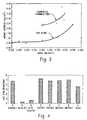
- the protein removal efficacyis not only a function of alkalinity in these optimized formulations, but on the other components of the composition. This is shown in FIGURE 3.
- the formulationsare primarily composed of three component parts: alkalinity ingredients, water control ingredients, and surfactants.
- the alkalinity ingredientsalso may act as water control agents.
- EDTAcontributes both alkalinity and water control characteristics to the formulations.
- Water control agentsare preferably included because the quality of the water used to clean surfaces varies considerably and can otherwise affect the efficacy of a given formulation.
- An exampleis water hardness, which displays inverse solubility, the higher the temperature the less soluble the water hardness salts are. Water hardness salts are also less soluble at higher pH values.
- the EDTA or other chelating agentsare preferably employed to keep the hardness salts in solution. All three of the above component parts are believed to function synergistically to enable the formulation to clean surfaces. This is demonstrated in FIGURE 3 which compares the alkalinity equivalents of nine commercial formulations (top curve) to that of. KOH (bottom curve) alone as the alkalinity source.
- the present inventorshave found that proper selection of the cleaning composition not only removes prions and other proteinaceous materials, but also at least partially deactivates the prions.
- alkaline cleanersare more effective in deactivating prions than enzymatic, neutral, or acid cleaners.
- IFDOileal fluid dependent organism
- the IFDOwas originally extracted from ileal fluid hence the name. It has since been found in other parts of the body.
- the IFDOhas shown a strong correlation with actual prions in its response to treatment processes and thus is proposed as a model for prion activity.
- the formulationswere prepared in water and an aliquot of IFDO suspended directly into each. The test solutions were incubated at 40°C for 30 minutes, aliquot sampled and quantified by serial dilution and plating into a modified growth agar.
- cleaner Ais a control of plain water
- cleaner Bis an alkaline cleaner (CIP150 TM )
- cleaner Cis a second, slightly less alkaline cleaner (CIP100 TM )
- cleaners DKlenzyme TM
- EEnzycare 2 TM
- cleaners FRenu-Klenz TM
- GNpH-Klenz TM
- cleaner HCIP 220 TM
- each of the tested cleanerswas obtained from STERIS Corp.
- alkali cleanersare not only more effective in removing prion material, they are also significantly more effective in deactivating what prion material might remain, as well as removed prion material still in solution.
- gaseous oxidizing agentsinclude hydrogen peroxide vapor, plasma/hydrogen peroxide or peracetic acid, plasma and/or vapor phase peracid, such as peracetic acid vapor, chlorine dioxide gas, and combinations of hydrogen peroxide with one or more peracids.
- vaporsuch as hydrogen peroxide vapor, is allowed to condense on items to be decontaminated.
- the condensed sterilantis reconverted to vapor and is removed from the items.
- a particularly preferred gaseous oxidantincludes hydrogen peroxide vapor. While the system will be described with particular reference to vapor hydrogen peroxide as the prion deactivation agent, it will be appreciated that other gaseous oxidizing agents are also contemplated.
- the items to be treated with the gaseous oxidant(which have already been cleaned with alkaline cleaning composition, rinsed, and preferably dried) are positioned in a sterilizing chamber or simply shrouded under a tent, a hood, or other covering.
- the vapor phase prion decontaminationtakes place at above ambient temperatures, more preferably, from about 25-60°C, most preferably, at about 45-55°C. It is also contemplated that the sterilization could occur in ambient conditions (15-30°C) provided there is a sufficient flow of sterilant vapor.
- hydrogen peroxide vaporis introduced to a chamber capable of being evacuated.
- the chamber containing the items to be treatedis first evacuated to a pressure of about 100 Torr (1.33 x 10 4 Pa) or below, most preferably, about 10 Torr (1.33 x 10 3 Pa) or less. If the item is not dry when placed in the chamber, the vacuum is held for a period sufficient to evaporate any liquid residue.
- Hydrogen peroxide vaporis then introduced to the chamber to contact the items. Applying a vacuum prior to introduction of hydrogen peroxide and/or between hydrogen peroxide pulses is believed to aid penetration of the vapor through packaging and into less accessible regions of the item, such as narrow lumens.
- the hydrogen peroxide concentrationis preferably maintained at below its saturation level to avoid condensation on the items and chamber walls, etc.
- the hydrogen peroxideis maintained at 75-95% saturation.
- the saturationis preferably close to 95%, and may even be higher if the % saturation can be maintained within even closer tolerances.
- two or more pulses of hydrogen peroxideare introduced to the chamber, each one preceded and followed by an evacuation step, as exemplified in FIGURE 5.
- a first stepis shown in FIGURE 5 as a leak test/conditioning step. This step is carried out in the absence of hydrogen peroxide and includes an evacuation step A (to about 10 Torr, or less), followed by a hold step B, where the pressure inside the chamber is monitored for leaks by observing pressure changes, if any.
- step Cdry air is introduced to the chamber to reduce the moisture in the chamber prior to introduction of hydrogen peroxide vapor.
- the chamberis evacuated once more at D to 10 Torr or less, prior to introduction of hydrogen peroxide at E raising the pressure to about 300-500 Torr.
- a dry gasis introduced to increase the pressure to 500-750 Torr.
- the hydrogen peroxidecontacts the instruments in the chamber for a period of several seconds to several minutes F, then is evacuated at G to a pressure of less than about 10 Torr.
- Steps E, F, and Gare repeated one or more times, shown as E', F', and G'.
- filtered airis introduced to the chamber at H and then evacuated at J to draw with it any remaining hydrogen peroxide which has adsorbed onto the items undergoing prion deactivation. Filtered air is again allowed into the chamber to bring the pressure up to atmospheric before opening the chamber.
- an exemplary prion decontamination cycleincludes four phases: dehumidification, conditioning, prion deactivation, and aeration.
- dehumidificationthe relative humidity is reduced, by drying the atmosphere in the chamber, to below 40% RH, e.g. to about 10-30% RH, for example, by circulating dry air through the chamber. Dry air may be provided by passing air through a desiccant cartridge or using a refrigerated system to extract the moisture.
- hydrogen peroxide vaporis produced by vaporizing a liquid mixture of hydrogen peroxide and water which is from 5-95% hydrogen peroxide, more preferably, 25-50% hydrogen peroxide, most preferably, 30-37% hydrogen peroxide.
- the vaporis introduced to the recirculating airflow and is carried into and through the chamber.
- the prion deactivation stepthen takes place over time.
- the recirculation flow rate, hydrogen peroxide pressure, and temperatureare measured and controlled to maintain steady state conditions.
- the concentration of hydrogen peroxideis maintained at below the condensation point of both the hydrogen peroxide and the water vapor to prevent condensation on the surfaces of the items and chamber walls.
- One embodimentincludes increasing the concentration of vapor to above the condensation point, allowing concentrated hydrogen peroxide to condense on contaminated surfaces, and then reforming the vapor during an aeration step by passing dry air over the surfaces.
- the concentration of hydrogen peroxide which can be maintained without condensationincreases exponentially with temperature. For example, at 20°C, about 1-2 mg/L can be maintained. At 30°C, 2-3 mg/L, at 40°C, 4-5 mg/L, and at 50°C, 8-9 mg/L can be maintained. However, at temperatures above about 60°C, hydrogen peroxide degradation tends to occur more rapidly and prions tend to agglomerate into tighter, harder to attack structures. Accordingly, a temperature of about 45-60°C is preferred, more preferably 53-57°C, although lower temperatures are effective when exposure times are significantly increased.
- a suitable prion deactivation vesselincludes a chamber wall 10, which defines an interior chamber 12 capable of being pressurized or evacuated.
- a vapor entry port 14 and an exit port 16are defined in the chamber wall.
- a generator 20,supplies the chamber 12 with a sterilant vapor, preferably a vaporized peroxy compound such as hydrogen peroxide, peracetic acid vapor, or mixture thereof, entrained in a carrier gas, such as air.
- a circulating systemincludes a vapor inlet line 24, which carries the vapor from the generator 20 to the entry port 14.
- the hydrogen peroxidepasses through the chamber 12 and leaves the chamber through the exit port 16.
- a return line 26returns the partially spent hydrogen peroxide vapor to the generator to be refreshed or, as shown in FIGURE 6, passes it through a destroyer 28 and a dryer 30.
- the destroyerconverts peroxide to water to be removed in the dryer 30.
- the hydrogen peroxide vaporis recirculated through the chamber for a period of time via a return line without refreshing the vapor with fresh hydrogen peroxide from the generator.
- the vapor leaving the chamber 12is directed through a catalytic converter 32 which converts the vapor to non-harmful products, such as water and oxygen.
- the vapor leaving the chamberis vented to the atmosphere where sunlight rapidly converts the vapor to water vapor and oxygen. Vaporized hydrogen peroxide is flowed through the chamber 12 until selected sterilization conditions are reached in terms of temperature, pressure, exposure time, and hydrogen peroxide concentration.
- an atmospheric systemallows input of vapor into an enclosure, holding it in the enclosure for a certain time, and evacuating or aerating the enclosure.
- the generator 20is preferably one which generates a controllable stream of vaporized hydrogen peroxide.
- a particularly preferred generatoris one which vaporizes droplets of liquid hydrogen peroxide by contact with a heated surface and entrains the vapor in a stream of carrier gas, such as air. The gas is then transported with the vapor to the chamber 12.
- hydrogen peroxideis generated in situ in the chamber, for example, by treating a compound which releases hydrogen peroxide, such as on heating.
- a compound which releases hydrogen peroxidesuch as on heating.
- other vaporization methodsmay be employed, such as introducing liquid hydrogen peroxide into an evacuated chamber where it is vaporized by the vacuum.
- the liquid hydrogen peroxideis optionally supplied to the generator from a single source 36 as a mixture of hydrogen peroxide in water for example, a 5-95% by weight hydrogen peroxide solution, more preferably, 30-37% hydrogen peroxide (FIGURE 8).
- the liquid componentsare entirely converted to vapor, so the resulting vapor has the same relative concentration of hydrogen peroxide as the liquid from which it is generated.
- the components of the vaporare separately contained or contained in higher and lower concentrations so that the composition of the vapor is adjustable by varying the rate of supply of each component to the vaporizer.
- the liquid hydrogen peroxide solutionis dripped or sprayed through a nozzle onto a heated surface (not shown), which vaporizes the oxidant without breaking it down.
- a heated surfacenot shown
- Other vaporizing techniquessuch as ultrasonic vaporizers, atomizers, and the like, are also contemplated.
- a sourcesuch as a reservoir 40 of more concentrated hydrogen peroxide and a source 42 of less concentrated hydrogen peroxide or water are connected with the vaporizer 20 by supply lines 44 and 46, respectively, so that the concentration of hydrogen peroxide in the liquid entering the vaporizer is adjustable.
- the mixture of water and hydrogen peroxide vaporis mixed with a carrier gas, such as air.
- a carrier gassuch as air.
- the carrier gasis supplied to the vaporizer through a line 48.
- a filtersuch as a HEPA filter 50, preferably filters the incoming air.
- the airis preferably passed through a drier 52, to remove moisture, and through a heater 54, to raise the temperature of the carrier gas, prior to mixing the carrier gas with the hydrogen peroxide vapor.
- First and second pumps 58, 60pump the hydrogen peroxide and water from the reservoirs 40 and 42.
- Separately adjustable regulator valves 62, 64regulate the fluid flow rate through the lines 44, 46.
- regulation of the flow ratesis adjusted by adjusting the pumping rate of the pumps 58, 60.
- a single pumpreplaces the two pumps 58, 60.
- a thermal jacket 68such as a water jacket or a resistance heater, optionally surrounds substantially all of the chamber 12.
- the jacket 68serves to maintain a selected temperature within the chamber.
- a heater 70connected to the thermal jacket 68 heats the jacket.
- the chamber 12is insulated to reduce heat loss from the chamber 12.
- additional insulation of unjacketed areas, such as doorsfurther serves to maintain the internal temperature of the chamber 12. Items to be deactivated are introduced to the chamber through a door (not shown).
- a biological indicator evaluator resistomer (BIER) vesselis optionally used.
- the BIER vesseloperates in a similar manner to the prion deactivation chamber described above, but allows a high level of control and monitoring of the chamber conditions to ensure reproducible results. Additionally, items to be tested are preferably introduced to the chamber through a port once conditions within the chamber have attained the selected conditions for the deactivation study, whereas in a normal prion deactivation system, items to be decontaminated are introduced through a conventional door prior to dehumidification and conditioning of the chamber.
- the BIER vesselis simply a standard vapor sterilization vessel which has been adapted for controlled investigation.
- the test couponsare introduced to the chamber through a small opening 80 formed in the door, or elsewhere in the chamber wall.
- An access port 82permits rapid insertion of items to be tested into the chamber without unduly perturbing the chamber conditions.
- the access portpreferably includes a hollow tube 84, which extends outwardly from the door around the opening 80.
- the tube 84defines an interior passageway 85, which is shaped to receive a sample holder or D-tube 86.
- the sample holder 86has a number of slots 88 or other receptacles for holding items, such as coupons contaminated with prion infected material or biological indicators, to be exposed to the chamber conditions.
- the access port 82is constructed to minimize the flow of gas or vapor into or out of the chamber 12 while the coupons and/or biological indicators are being admitted to the chamber 12 to avoid perturbing the equilibrium conditions.
- the contaminated coupons or biological indicatorsare thus exposed relatively instantaneously to the preselected equilibrium sterilization conditions.
- two seals 90, 92are mounted within the tube 84, which form a seal between the sample holder and the tube during insertion and removal.
- the tube interior passageway 85is closed by a valve 96.
- test coupons and/or indicatorsare removed from the chamber 12, and evaluated for remaining prion activity and/or microbial activity.
- a fan, or fans, 104preferably disposed within the chamber 12, mix the gases within the chamber, thereby improving the uniformity of the mixture and increasing the rate of flow of sterilant over the biological indicators.
- Perforated upper and lower plates 106 and 108, respectively,are optionally disposed within the chamber 12 to induce a laminar flow of gas through the chamber 12.
- the flow of vaporized hydrogen peroxide from the generatoris further controlled by a flow control device 110, such as a pump, vacuum source or blower, damper, or other regulator, which serves to regulate the flow of vaporized hydrogen peroxide into or out of the chamber.
- a flow control device 110such as a pump, vacuum source or blower, damper, or other regulator, which serves to regulate the flow of vaporized hydrogen peroxide into or out of the chamber.
- the flow control 110is located in inlet line 24 or return line 26.
- Probes 160such as temperature, pressure and humidity probes, disposed within the chamber 12, serve to measure the chamber environment.
- the probesare connected to a monitor 162, which monitors the changes in environmental conditions.
- the monitor 162signals a controller 164 which controls the environmental conditions within the chamber 12 by controlling the heater 70 for regulating the temperature of the thermal jacket 68 and also the operation of the flow control 110, the vaporized hydrogen peroxide generator 20, the pumps 58, 60, and the valves 62, 64.
- a sensor 166is also positioned within the chamber to detect hydrogen peroxide concentration directly and/or detect the concentration of other components of the vapor from which the hydrogen peroxide concentration can be established indirectly.
- a vacuum sourcesuch as a pump 170 evacuates the chamber before, during, or after the sterilization process.
- a three way valve 172 in line 26is connected to the vacuum pump 170. By switching the valve 172 between a first position, in which chamber gases passing through line 26 are returned to the generator, to a second position in which the chamber gases are directed to the pump 170, the chamber 12 is evacuated.
- a catalytic converter 174 and a drier 176decompose the peroxy vapor and dry and heat the air before it is reintroduced into the generator 20.
- the BIER vessel systemis used without recirculation of hydrogen peroxide or carrier gas.
- the mixture of air and hydrogen peroxideflows through the chamber 12 in a single pass then is vented from the chamber via the catalytic converter 174. This provides for better control of the system.
- the controller 164controls one or more of the chamber temperature, chamber pressure, vaporization rate, hydrogen peroxide concentration in the liquid to be vaporized, or vapor flow rate through the chamber in response to measured conditions to maintain the desired prion deactivation conditions within the chamber during an exposure cycle.
- the instruments or other partially, grossly cleaned itemsare advantageously transported to the chamber of the prion decontamination system without aeration and drying. Any moisture present on the instruments is removed during the preconditioning/dehumidification phases.
- the instrumentsare wrapped in a sterile wrap, such as gauze or Tyvek TM wrap, prior to subjecting the instruments to hydrogen peroxide decontamination.
- a sterile wrapsuch as gauze or Tyvek TM wrap
- a number of alternative cleaning and decontaminating proceduresare also contemplated.
- a combined cleaning and sterilization systemmay be used.
- itemsmay be placed in an enclosed tray for sterilization and/or cleaning. Such a tray may be sealed after the decontamination process is complete to maintain the sterility of the items until reuse.
- a prion deactivation process involving an alkaline cleaning step followed by a hydrogen peroxide or other vapor sterilant stepis not only effective for removing/and or deactivating prions but also is effective for sterilization of the items.
- medical instruments and other devicesneed not be subjected to a separate sterilization process to ensure that microorganisms which may pose hazards to patients or those handling the instruments are also destroyed.
- a combination of an alkaline cleaning product wash at an alkali concentration of about 0.02M to about 0.2M followed by a vapor hydrogen peroxide treatmentis an effective alternative to a conventional treatment (1N NaOH and/or heating to 120°C for one hour followed by microbial decontamination) and is less damaging to the medical instruments or other items being treated.
- a liquid sterilization/prion deactivation stepoptionally precedes the gaseous oxidant step.
- instrumentsare alkaline cleaned, rinsed, sterilized with a peracetic acid solution, wrapped in a sterile wrap or placed in a tray, then finally sterilized/prion deactivated with hydrogen peroxide.
- an apparatuswhich acts as both a washer and a prion decontamination vessel is used. This avoids the need to remove the alkaline-cleaned items and transport them to a separate vapor treatment vessel.
- the deviceis similar to that shown in FIGURE 6. Like parts are identified with a prime (') with new components given new numbers. Items are loaded into a chamber 10' of the apparatus and washed with an alkaline cleaner and rinsed.
- a first cleaning stepuses a first cleaner (e.g., alkaline). This is followed by a rinse step, then another cleaning step with a second cleaner (e.g., enzymatic) and a further rinse step.
- the concentrated alkaline cleaneris supplied in liquid or solid form to a well 180.
- Water(preferably heated to about 50-60°C) is introduced to the well through a flow line 182 and carries the alkaline or other cleaner in solution to nozzles 184 located in the chamber 10′.
- An agitator 186agitates the liquid in the chamber.
- a pump 187supplies the cleaning solution to spray nozzles under pressure.
- the alkaline cleaneris emptied from the chamber via a drain line 188.
- Rinse wateris introduced to the chamber for one or more rinse cycles and drained. The moisture in the chamber is then reduced by flowing dry air through the chamber from line 48'.
- the chamberis capable of withstanding below atmospheric pressures and is evacuated with a vacuum pump 110 '.
- Hydrogen peroxide vapor from a generator 20is then introduced to the chamber mixed with the sterile air.
- the hydrogen peroxide/carrier gasis flowed through the chamber for a sufficient time to effect prion deactivation.
- a pulse system similar to that described above in connection with FIGURE 5is used. In this system, the chamber is evacuated and then a pulse or pulses of hydrogen peroxide vapor are introduced.
- the chamberis preferably fitted with temperature and pressure probes, chemical sensors, and a control system similar to those previously described in connection with FIGURE 7 to allow careful monitoring and control of conditions within the chamber.
- Valves 190, 192are provided for selectively closing off the vapor and cleaning liquid supplies, respectively.
- one or more items to be washed and prion decontaminatedare enclosed in a tray 194 connected with vapor and cleaning liquid ports 14' and 184.
- the cleaning fluid and/or vaporis flowed through the tray.
- valves 196, 198are closed to seal access to the tray, thus sealing the tray against airborne contaminant ingress until use.
- Couponsare prepared by dropping aliquots of a suspension of IFDO in water onto stainless steel coupons which are then dried. The coupons are placed into pouches formed from tyvekTM wrap. the wrapped coupons are exposed to hydrogen peroxide at 1.5 mg/L and 30°C, or 3.0 mg/L and 40°C.
- Figure 11shows the concentration of IFDO remaining on the coupons over time. The effects of higher temperatures and concentrations are significant.
- Samplesare prepared similar to those for Example A, but in this case are further contaminated with 0, 10, or 50% blood.
- the samplesare exposed to vapor hydrogen peroxide sterilization cycles as shown in FIGURE 12, with either three or six pulses of hydrogen peroxide vapor at 30°C or 50°C.
- the results shown in Table 1indicate the importance of cleaning items prior to a prion decontamination step.
- TABLE 1 Temperature (°C) Vapor Hydrogen Peroxide Conc. (mg/L)No. of Pulses Soil Log Reduction (IFDO) 30 2.0 6 None >7 30 2.0 6 10% blood 4-5 30 2.0 6 50% blood 1-2 50 7.0 3 None >7 50 7.0 3 10% blood >7 50 7.0 3 50% blood 3-4
- a vapor hydrogen peroxide cyclecan be effective at removal of prions, particularly when a 50 °C cycle and a 7.0 mg/L hydrogen peroxide concentration are employed.
- Couponsare prepared by dropping aliquots of a suspension of human CJD-contaminated brain homogenate in water onto stainless steel coupons which are then dried. The coupons are placed into pouches formed from Tyvek TM wrap. The wrapped coupons are exposed to various treatment processes, without a precleaning step, either at atmospheric pressure or under vacuum conditions, both with and without hydrogen peroxide. After exposure, the coupons are extracted in phosphate buffer saline by sonification. The extracts are concentrated, separated by SDS-PAGE, and Western blotted. The presence or absence of prion protein (P R P BC ) is determined using an antibody array. The results shown in Table 2 indicate that vapor hydrogen peroxide is effective at destruction of the harmful form of the prion protein.
Landscapes
- Health & Medical Sciences (AREA)
- Chemical & Material Sciences (AREA)
- Life Sciences & Earth Sciences (AREA)
- General Health & Medical Sciences (AREA)
- Veterinary Medicine (AREA)
- Public Health (AREA)
- Epidemiology (AREA)
- Animal Behavior & Ethology (AREA)
- Chemical Kinetics & Catalysis (AREA)
- Engineering & Computer Science (AREA)
- Medicinal Chemistry (AREA)
- General Chemical & Material Sciences (AREA)
- Biomedical Technology (AREA)
- Molecular Biology (AREA)
- Inorganic Chemistry (AREA)
- Plasma & Fusion (AREA)
- Pharmacology & Pharmacy (AREA)
- Physics & Mathematics (AREA)
- Oil, Petroleum & Natural Gas (AREA)
- Wood Science & Technology (AREA)
- Organic Chemistry (AREA)
- Apparatus For Disinfection Or Sterilisation (AREA)
- Detergent Compositions (AREA)
- Cleaning By Liquid Or Steam (AREA)
Abstract
Description
- The present invention relates to the field of biological decontamination. The invention finds particular application in connection with the removal and/or destruction of harmful biological materials, such as prions (proteinaceous-infectious agents), from medical, dental, and pharmaceutical instruments and will be described with particular reference thereto. It will be appreciated, however, that the method and system of the present invention may be utilized in biological decontamination of a wide range of equipment, instruments, and other surfaces contaminated with prion infected material, such as pharmaceutical preparation facilities, food processing facilities, laboratory animal research facilities including floors, work surfaces, equipment, cages, fermentation tanks, fluid lines, and the like.
- The term "Prion" is used to describe proteinaceous-infectious agents that cause relatively similar brain diseases in humans and/or in animals, which are invariably fatal. These diseases are generally referred to as transmissible spongiform encephalopathies (TSEs). TSEs include Creutzfeldt-Jakob disease (CJD) and variant CJD (vCJD) in humans, Bovine Spongiform Encephalopathy (BSE) in cattle, also know as "Mad Cow Disease," Scrapie in sheep, and Wasting Disease in elk. All of these diseases attack the neurological organs of the animal or animals which are susceptible to the particular disease. They are characterized by initially long incubation times followed by a short period of neurological symptoms, including dementia and loss of coordination, and eventually death.
- The infectious agent responsible for these diseases is thought to be a simple protein, with no associated nucleic acids. The pathogenic mechanism for such prion diseases is proposed to involve an initially normal host encoded protein. The protein undergoes a conformational change to an abnormal form (a prion), which has the ability of self-propagation. The exact cause of this change is, at present, unknown. The abnormal form of the protein is not broken down effectively in the body and its accumulation in certain tissues (in particular neural tissue) eventually causes tissue damage, such as cell death. Once significant neural tissue damage has occurred, the clinical signs are observed.
- Prion diseases may thus be classified as protein aggregation diseases, which also include several other fatal diseases, such as Alzheimer's disease and amyloidosis. In the case of CJD, the most prevalent prion disease in humans (occurring in roughly 1:1,000,000 of the population), about 85% of cases are thought to arise sporadically, about 10% are thought to be inherited, and about 5% arise iatrogenically.
- Although not considered to be highly contagious, prion diseases can be transmitted by certain high risk tissues, including the brain, spinal cord, cerebral spinal fluids, and the eye. After a surgical procedure on a prion infected patient, prion containing residue may remain on the surgical instruments, particularly neurosurgical and ophthalmological instruments. During the long incubation period, it is extremely difficult to determine whether a surgical candidate is a prion carrier.
- Different levels of microbial decontamination are recognized in the art. For example, sanitizing connotes free from dirt or germs by cleaning. Disinfecting calls for cleansing in order to destroy harmful microorganisms. Sterilization, the highest level of biological contamination control, connotes the destruction of all living microorganisms.
- It is now known that certain biological materials which do not live or reproduce in the conventional sense, such as prions, are nevertheless capable of replication and/or transformation into harmful entities. We use herein the term "deactivation" to encompass the destruction of such harmful biological materials, such as prions, and/or their ability to replicate or undergo conformational changes to harmful species.
- Vapor phase sterilization is a known technique for decontaminating or sterilizing the outer surfaces of reusable medical instruments and has been adapted to interstitial sterilization through the selective application of below atmospheric pressures. During vapor phase sterilization, medical instruments are placed in an enclosed space or chamber where sterilization occurs. The items to be sterilized are subjected to either a "deep vacuum" approach or a "flow through" approach. A liquid sterilant is vaporized in a heated vaporizer. Once vaporized, a deep vacuum is used to pull the sterilant vapor into the evacuated and sealed chamber. In the flow through approach, vaporized sterilant is mixed with a flow of carrier gas that delivers the sterilant vapor into, through and out of the chamber. The chamber may be at slightly negative or positive pressure.
- For example,
Edwards, et al., U.S. Patent No. 5,779,973 discloses vapor hydrogen peroxide sterilization of plastic-overwrapped IV bags. An open flow-through system is disclosed in Childers,U.S. Patent No. 5,173,258 . - Further prior art is disclosed in
J.C. DARBORD: "Inactivation of prions in daily medical practice" BIOMEDICINE & PHARMACOTHERAPY, vol. 53, 1999, pages 34-38,
W.A. RUTALA ET AL: "Creutzfeldt-Jakob Disease:Recommendations for Disinfection and Sterilization" CLINICAL INFECTIOUS DISEASES, vol. 32, no.9, May 2001 (2001-05), pages 1348-1356, - Both citations are related to the inactivation of prions from medical devices. The first mentioned citation discloses a method for deactivation using 1 N sodium hydroxide solution, autoclaving at 134° to 138° C and soaking in chlorine bleach (see p. 36 to 37). The second one discusses several decontamination methods of medical devices.
- Prions, however, are notoriously very hardy and demonstrate resistance to routine methods of decontamination and sterilization. Unlike microorganisms, prions have no DNA or RNA to destroy or disrupt. Prions, due to their hydrophobic nature, tend to aggregate together in insoluble clumps. Under many conditions that lead to successful sterilization in microorganisms, prions form tighter clumps which protect themselves and underlying prions from the sterilization process. The World Health Organization (1997) protocol for prion deactivation calls for soaking the instrument in concentrated sodium hydroxide or hypochlorite for two hours followed by one hour in an autoclave. These aggressive treatments are often incompatible with medical devices, particularly flexible endoscopes and other devices with plastic, brass, or aluminum parts. Many devices are damaged by exposure to high temperatures. Chemical treatments, such as strong alkali, are damaging to medical device materials or surfaces in general. Glutaraldehyde, formaldehyde, ethylene oxide, liquid hydrogen peroxide, most phenolics, alcohols, and processes such as dry heat, boiling, freezing, UV, ionizing, and microwave radiation have generally been reported to be ineffective. There is a clear need for products and processes that are effective against prions yet compatible with surfaces.
- The present invention provides a new and improved apparatus and method of treatment of surfaces contaminated with prion-infected material which overcome the above-referenced problems and others.
- In accordance with one aspect of the present invention, a method of deactivating prions is provided. The method includes pretreating surfaces that carry prion infected material with a cleaner that attacks prions and treating the surfaces with an oxidizing agent in gaseous form.
- In accordance with another aspect of the present invention, a prion deactivation system for removing and deactivating prions on an item is provided. The system includes a chamber for receiving the item. A well is fluidly connected with the chamber for receiving a concentrated alkaline cleaner. A supply of water is fluidly connected with the well for providing water to mix with the concentrated alkaline cleaner and form an alkaline cleaning solution. A source of hydrogen peroxide vapor is fluidly connected with the chamber.
- One advantage of the present invention is that it is gentle on instruments.
- Another advantage of the present invention is that it deactivates prions quickly and effectively.
- Another advantage of the present invention is that it is compatible with a wide variety of materials and devices.
- Still further advantages of the present invention will become apparent to those of ordinary skill in the art upon reading and understanding the following detailed
- The invention may take form in various components and arrangements of components, and in various steps and arrangements of steps. The drawings are only for purposes of illustrating a preferred embodiment and are not to be construed as limiting the invention.
- FIGURE 1 illustrates proteinaceous material removal with various cleaning compositions;
- FIGURE 2 graphs proteinaceous material versus alkalinity;
- FIGURE 3 compares the effect of KOH concentration alone and overall alkalinity in the cleaning formulations in proteinaceous material removal;
- FIGURE 4 compares the efficacy of various cleaning compositions in the reduction of a prion (IFDO) model;
- FIGURE 5a is a plot showing pressure changes in an exemplary vacuum prion deactivation cycle;
- FIGURE 5b is a plot showing an exemplary atmospheric cycle;
- FIGURE 6 is a diagrammatic illustration of a prion deactivation system;
- FIGURE 7 shows the prion deactivation system of FIGURE 6 adapted for control and evaluation of deactivation conditions; and
- FIGURE 8 is a diagrammatic illustration of an alternative embodiment of a prion deactivation system;
- FIGURE 9 is a plot of log IFDO versus time for three prion deactivation cycles (ATM = atmospheric conditions);
- FIGURE 10 is a schematic illustration of a combined washer and prion deactivation system;
- FIGURE 11 is a plot of IFDO concentration versus time for IFDO inoculated coupons exposed to hydrogen peroxide vapor at 1.5 mg/L and 30°C and at 3.0 mg/L and 40°C; and
- FIGURE 12 is a schematic illustration of an exemplary vacuum/vapor hydrogen peroxide cycle.
- A method for microbial decontamination and prion deactivation of instruments or other items which carry material which may be contaminated with prions includes a cleaning operation using an alkaline cleaner, followed by treatment with a gaseous or vapor phase oxidizing agent. A preferred method of cleaning and decontaminating a surface which has been contaminated with a biological material that includes prions includes cleaning the surface with an alkaline cleaner which has a pH of at least 10 and exposing the cleaned surface to a vapor which includes hydrogen peroxide for a sufficient time to destroy viable prions on the surface.
- The cleaner composition is preferably formed by dilution of a concentrate which includes an alkaline cleaning agent, and optionally includes one or more of the following: a surfactant, a chelating agent, an anti-redeposition agent, a cationic polymer, and a metal corrosion inhibitor. Alternatively, the components of the cleaning composition are separately mixed with water or other suitable solvent.
- The alkaline cleaning agent is preferably a hydroxide of an alkali metal or an earth alkali metal. Exemplary alkaline cleaning agents are potassium hydroxide and sodium hydroxide. The hydroxide is preferably present at from 20-60% by weight of the concentrate.
- The chelating agent is provided for chelating with water hardness salts, such as salts of calcium and magnesium, which become deposited on the equipment to be cleaned. Suitable chelating agents include, but are not limited to, carboxylic acid-based polymers, such as polyacrylic acid, and ethylenediaminetetraacetic acid (EDTA) or salts thereof. Sodium hexametaphosphate, discussed below, also acts as a chelating agent to some extent. The chelating agent is preferably present from about 1-15% by weight of the concentrate. A preferred concentrate composition includes 2-10% by weight of Na-EDTA and 0.1-30% by weight of polyacrylic acid.
- The surfactant is selected from the group consisting of anionic, cationic, nonionic, and zwitterionic surfactants to enhance cleaning performance. Examples of such surfactants include but are not limited to water-soluble salts or higher fatty acid monoglyceride monosulfates, such as the sodium salt of the monosulfated monoglyceride of hydrogenated coconut oil fatty acids, higher alkyl sulfates such as sodium lauryl sulfate, alkyl aryl sulfonates such as sodium dodecyl benzene sulfonate, higher alkyl sulfoacetates, higher fatty acid esters of 1,2 dihydroxy propane sulfonates, and the substantially saturated higher aliphatic acyl amides of lower aliphatic amino carboxylic acid compounds, such as those having 12 to 16 carbons in the fatty acid, alkyl or acyl radicals, and the like. Examples of the last mentioned amides are N-lauroyl sarcosine, and the sodium, potassium, and ethanolamine salts of N-lauroyl, N-myristoyl, or N-palmitoyl sarcosine.
- Additional examples are condensation products of ethylene oxide with various reactive hydrogen-containing compounds reactive therewith having long hydrophobic chains (e.g. aliphatic chains of about 12 to 20 carbon atoms), which condensation products ("ethoxamers") contain hydrophilic polyoxyethylene moieties, such as condensation products of poly (ethylene oxide) with fatty acids, fatty alcohols, fatty amides, polyhydric alcohols (e.g. sorbitan monostearate) and polypropyleneoxide (e.g. Pluronic materials).
- Suitable amphoteric surfactants are alkyl amphocarboxylates, such as mixed C-8 amphocarboxylate surfactants. A preferred concentrate includes mixed C8 amphocarboxylates at a concentration of about 0-5% by weight.
- The anti-redeposition agent inhibits redeposition of soil on the equipment. Suitable anti-redeposition agents include gluconates, such as sodium gluconate, and citrate salts. Polyacrylic acid also acts as an anti-redeposition agent. The anti-redeposition agent is preferably at a concentration of 1-10% by weight of the concentrate composition. A particularly preferred composition includes polyacrylic acid at a concentration of 0.1-3% by weight, more preferably about 0.3% by weight, and sodium gluconate at a concentration of 1-10% by weight, more preferably about 1-5% by weight of the composition.
- The cationic polymer aids in maintaining magnesium, silicate, and zinc compounds in solution, maintains corrosion inhibitors in solution, and aids in preventing water-hardness precipitation and scaling on the cleaning equipment surfaces when the cleaning composition is used in hard water. Exemplary of such cationic polymers are carboxylated polymers which may be generically categorized as water-soluble carboxylic acid polymers, such as polyacrylic or polymethacrylic acids or vinyl addition polymers. Of the vinyl addition polymers contemplated, maleic anhydride copolymers as with vinyl acetate, styrene, ethylene, isobutylene, acrylic acid and vinyl ethers are
- Exemplary cationic polymers are dialkyldiallyl ammonium salt (e.g., halide) homopolymers or copolymers, such dimethyldiallyl ammonium chloride homopolymer, dimethyldiallyl ammonium chloride/acrylamide copolymer, dimethyldiallyl ammonium chloride/acrylic acid copolymer, and vinyl imidazolevinyl pyrrolidone copolymers. Other suitable non-cellulosic cationic polymers are disclosed in the CTFA Cosmetic Ingredient Dictionary under the designation "Polyquaternium" followed by a whole number. All of the above-described polymers are water-soluble or at least colloidally dispersible in water. Such low molecular weight carboxylated polymers, molecular weight range from about 1,000 to less than 100,000, act as antinucleating agents to prevent carbonate from forming undesirable scaling in wash tanks.
Polyquaternium 7, a dimethyldiallyl ammonium chloride/acrylamide copolymer, is exemplary. The cationic polymer is preferably present at 0-10% by weight of the concentrate. - Exemplary metal corrosion inhibitors are silicic acid salts and phosphoric acid salts in an amount of about 0-10% weight % of the concentrate.
- Concentration ranges of a preferred alkali cleaner concentrate are shown inTABLE 1.
TABLE 1 Ingredient Recommended Range, wt. % in concentrate 45% Potassium hydroxide 45-90 40% Ethylenediamine tetraacetic acid (EDTA), tetrasodium salt 1-20 Sodium gluconate 0-7 30% 2-Propenoic acid homopolymer (Polyacrylic acid) 1-20 Mixed C8 amphocarboxylates 0-5 Sodium hexametaphosphate 0-10 40% silicic acid, sodium salt 0-10 48% acrylic acid homopolymer 1-20 Dimethyldiallyl ammonium chloride and acrylamide copolymer (Polyquaternium 7) 0-10 - In particular, the following formulations are specified inTABLE 2.
TABLE 2 Component Formulation A wt % in Cleaner Concentrate Formulation B wt % in Cleaner Concentrate 45% Potassium hydroxide 69 46 40% Ethylene diamine tetraacetic acid, tetrasodium salt 20 10 Sodium gluconate 1 5 30% 2-Propenoic acid homopolymer (Polyacrylic acid) 3 1 Mixed C8 amphocarboxylates 0 2 Sodium hexametaphosphate 0 10 Softened water 7 26 - Note that inTABLES 1 and2, many of the ingredients are already partially diluted. Thus, for example, the actual concentration of potassium hydroxide in Formulation A of the concentrate is actually about 30% by weight and in Formulation B, about 21% by weight.
- To perform the cleaning operation, the cleaning concentrate is diluted in water at about 8-16 cc/liter and the items to be cleaned treated with the cleaning solution, preferably combined with agitation, at 30 to 65°C for 2-30 minutes. A typical overall cycle in an automatic washer may include a two minute pre-wash with water at 30-65°C, a 2-30 minute wash with the alkaline cleaner at 8-16 cc/liter, a 15 second rinse in water, a one minute thermal rinse at 30-65°C, and finally a drying step (if required). An alternative cycle may simply involve prerinsing, alkaline cleaning, and post-rinsing as described above.
- The cleaning concentrate optionally includes a low level of an antimicrobial agent, such as a phenol, quaternary ammonium compound, oxidizing agent, e.g., sodium hypochlorite, hydrogen peroxide, or peracetic acid, or combination thereof.
- Other cleaners are also contemplated. Cleaners fall into various categories. Enzymatic cleaners include active proteases, lipases, and other enzymes to aid in tissue or soil breakdown on a surface. These products assist in removing prion and other proteinaceous materials, but generally lack efficacy against prions, i.e., prions are protease resistant. Non-enzymatic cleaners may be broken down into neutral, acidic, and alkali based products. These cleaners include a variety of excipients that aid in soil removal from a surface such as wetting agents and surfactants.
- Cleaning agents with a range of pHs were tested against a prion model for prion removal efficacy. Bovine serum albumin (BSA), like prions, is proteinaceous in nature and has been shown to exhibit responses to treatment processes which correlate with the response of prions under similar treatments. More specifically, a 5% BSA solution was prepared and 2 ml pipetted onto each of like stainless steel coupons. These coupons were dried at 43°C in an oven for one hour, cooled to room temperature, and weighed. Under these drying conditions, bovine serum albumin adopts a highβ-sheet conformation which is similar to infectious prion protein. The coupons were washed in a STERIS 444™ washer/disinfector using its instrument cycle, but with different cleaning compositions. The instrument cycle includes a 2 minute prewash, a 2 minute wash at 65°C, a rinse, a thermal rinse, and a drying cycle. Following the cycle, the coupons were removed from the washer, cooled, and weighed.FIGURE 1 shows the amount of material removed in the washing cycle where compositions A, B, C, and D are alkaline cleaners with decreasing alkalinity from A-D, composition E is a neutral cleaner (Renu-Klenz™, obtainable from STERIS Corp., Mentor OH), composition F is an acid cleaner (CIP-220™, obtainable from STERIS Corp.), and composition G is a plain water control. FIGURE 2 is a graph of the material removed versus theoretical total alkalinity in parts per million. As shown in FIGURE 2, there is a strong correlation between the amount of material removed and the alkalinity, the amount increasing with the total alkalinity of the cleaning composition.
- The cleaning composition used as described removes fixed proteinaceous matter including clumps of protein. Any remaining proteinaceous substances are in the form of a thin film which is more easily penetrated by the deactivating agent in a subsequent deactivation step. Moreover, the preferred alkaline cleaner results in about a 50% destruction of prions in the residual film that is not removed during the cleaning step.
- Optimized alkaline cleaning formulations based onTABLE 1 were developed and analyzed as described above with the following results:
TABLE 3 Formulation Average Protein Removed (mg/cm2) Standard Deviation Equivalent [KOH], M, in washer Water Control 0.5 0.04 0 Alkaline 12.36 0.57 0.020 Alkaline 2 (A) 4.18 0.52 0.033 Alkaline 32.97 0.75 0.031 Alkaline 4 2.52 0.29 0.029 Alkaline 53.56 0.18 0.035 Alkaline 62.44 0.49 0.020 Alkaline 72.32 0.30 0.020 Alkaline 83.11 0.17 0.033 Alkaline 9 2.85 0.74 0.034 Alkaline 103.46 0.55 0.034 Alkaline 11 3.53 0.52 Not determined Alkaline 12(B) 4.06 0.40 Not determined Alkaline 13 3.34 0.42 Not determined Alkaline 14 3.49 0.20 Not determined Alkaline 15 3.28 0.75 Not determined - The compositions of the most effective formulations (labeled A and B) are specified above inTABLE 2. Preferred cleaners have an alkalinity equivalent to 0.030 M KOH, or above and a pH of at least 10, preferably, pH 13, or higher.
- The protein removal efficacy is not only a function of alkalinity in these optimized formulations, but on the other components of the composition. This is shown in FIGURE 3. The formulations are primarily composed of three component parts: alkalinity ingredients, water control ingredients, and surfactants. The alkalinity ingredients also may act as water control agents. For example, EDTA contributes both alkalinity and water control characteristics to the formulations. Water control agents are preferably included because the quality of the water used to clean surfaces varies considerably and can otherwise affect the efficacy of a given formulation. An example is water hardness, which displays inverse solubility, the higher the temperature the less soluble the water hardness salts are. Water hardness salts are also less soluble at higher pH values. Therefore, the EDTA or other chelating agents are preferably employed to keep the hardness salts in solution. All three of the above component parts are believed to function synergistically to enable the formulation to clean surfaces. This is demonstrated inFIGURE 3 which compares the alkalinity equivalents of nine commercial formulations (top curve) to that of. KOH (bottom curve) alone as the alkalinity source.
- The effect of alkalinity alone was evaluated by adding the respective proportion of potassium hydroxide (KOH) to the washer and testing as described above. Although the effect of alkalinity (expressed as the molarity of KOH) was significant (as demonstrated in the bottom curve ofFIGURE 3), the formulations tested (examples 1 to 9 fromTABLE 3) demonstrated enhanced efficiency of protein removal, e.g. at 0.02 M, the commercial formulations removed 2-2.5 mg/cm2 protein whereas KOH alone removed less than 1 mg/cm2 of protein.
- The present inventors have found that proper selection of the cleaning composition not only removes prions and other proteinaceous materials, but also at least partially deactivates the prions. Particularly, alkaline cleaners are more effective in deactivating prions than enzymatic, neutral, or acid cleaners.
- A variety of cleaners were tested against a prion model in which an ileal fluid dependent organism (IFDO) was artificially cultured in modified Mycoplasma based broth, quantified by serial dilutions, and plated on a similar agar. The IFDO was originally extracted from ileal fluid hence the name. It has since been found in other parts of the body. The IFDO has shown a strong correlation with actual prions in its response to treatment processes and thus is proposed as a model for prion activity. The formulations were prepared in water and an aliquot of IFDO suspended directly into each. The test solutions were incubated at 40°C for 30 minutes, aliquot sampled and quantified by serial dilution and plating into a modified growth agar. Following incubation at 37°C for 48 hours, the plates were counted and log reductions in the IFDO present obtained. These test results are illustrated in FIGURE 4, where cleaner A is a control of plain water, cleaner B is an alkaline cleaner (CIP150™ ), cleaner C is a second, slightly less alkaline cleaner (CIP100™), cleaners D (Klenzyme™) and E (Enzycare 2™) are enzyme cleaners, cleaners F (Renu-Klenz™) and G (NpH-Klenz™) are neutral cleaners, and cleaner H (CIP 220™) is an acid cleaner (each of the tested cleaners was obtained from STERIS Corp.).
- Thus, alkali cleaners are not only more effective in removing prion material, they are also significantly more effective in deactivating what prion material might remain, as well as removed prion material still in solution.
- After the cleaning step, the instruments or other items are subject to a prion deactivation step. During the prion deactivation step, the items are contacted with a gaseous, plasma, or vapor phase oxidizing agent, all of which will be referred to herein as gaseous oxidizing agents. Preferred gaseous oxidizing agents include hydrogen peroxide vapor, plasma/hydrogen peroxide or peracetic acid, plasma and/or vapor phase peracid, such as peracetic acid vapor, chlorine dioxide gas, and combinations of hydrogen peroxide with one or more peracids. In one embodiment, vapor, such as hydrogen peroxide vapor, is allowed to condense on items to be decontaminated. In a subsequent aeration or evacuation step, the condensed sterilant is reconverted to vapor and is removed from the items. A particularly preferred gaseous oxidant includes hydrogen peroxide vapor. While the system will be described with particular reference to vapor hydrogen peroxide as the prion deactivation agent, it will be appreciated that other gaseous oxidizing agents are also contemplated.
- The items to be treated with the gaseous oxidant (which have already been cleaned with alkaline cleaning composition, rinsed, and preferably dried) are positioned in a sterilizing chamber or simply shrouded under a tent, a hood, or other covering. Preferably, the vapor phase prion decontamination takes place at above ambient temperatures, more preferably, from about 25-60°C, most preferably, at about 45-55°C. It is also contemplated that the sterilization could occur in ambient conditions (15-30°C) provided there is a sufficient flow of sterilant vapor.
- In one embodiment, hydrogen peroxide vapor is introduced to a chamber capable of being evacuated. The chamber containing the items to be treated is first evacuated to a pressure of about 100 Torr (1.33 x 10⁴Pa) or below, most preferably, about 10 Torr (1.33 x 10³Pa) or less. If the item is not dry when placed in the chamber, the vacuum is held for a period sufficient to evaporate any liquid residue. Hydrogen peroxide vapor is then introduced to the chamber to contact the items. Applying a vacuum prior to introduction of hydrogen peroxide and/or between hydrogen peroxide pulses is believed to aid penetration of the vapor through packaging and into less accessible regions of the item, such as narrow lumens. The hydrogen peroxide concentration is preferably maintained at below its saturation level to avoid condensation on the items and chamber walls, etc. For example, the hydrogen peroxide is maintained at 75-95% saturation. Where the chamber is capable of accurately maintaining % saturation to within 1-5%, the saturation is preferably close to 95%, and may even be higher if the % saturation can be maintained within even closer tolerances.
- In a preferred embodiment, two or more pulses of hydrogen peroxide are introduced to the chamber, each one preceded and followed by an evacuation step, as exemplified inFIGURE 5. A first step is shown inFIGURE 5 as a leak test/conditioning step. This step is carried out in the absence of hydrogen peroxide and includes an evacuation stepA (to about 10 Torr, or less), followed by a hold stepB, where the pressure inside the chamber is monitored for leaks by observing pressure changes, if any. During step C, dry air is introduced to the chamber to reduce the moisture in the chamber prior to introduction of hydrogen peroxide vapor. The chamber is evacuated once more atD to 10 Torr or less, prior to introduction of hydrogen peroxide atE raising the pressure to about 300-500 Torr. Optionally, a dry gas is introduced to increase the pressure to 500-750 Torr. The hydrogen peroxide contacts the instruments in the chamber for a period of several seconds to several minutesF, then is evacuated atG to a pressure of less than about 10 Torr. StepsE, F, andG are repeated one or more times, shown asE', F', andG'. In a final aeration step, filtered air is introduced to the chamber atH and then evacuated atJ to draw with it any remaining hydrogen peroxide which has adsorbed onto the items undergoing prion deactivation. Filtered air is again allowed into the chamber to bring the pressure up to atmospheric before opening the chamber.
- Alternatively, prion decontamination with hydrogen peroxide takes place under atmospheric or above atmospheric conditions. When atmospheric or above atmospheric pressures are used, an exemplary prion decontamination cycle includes four phases: dehumidification, conditioning, prion deactivation, and aeration. During dehumidification, the relative humidity is reduced, by drying the atmosphere in the chamber, to below 40% RH, e.g. to about 10-30% RH, for example, by circulating dry air through the chamber. Dry air may be provided by passing air through a desiccant cartridge or using a refrigerated system to extract the moisture. During the conditioning step, hydrogen peroxide vapor is produced by vaporizing a liquid mixture of hydrogen peroxide and water which is from 5-95% hydrogen peroxide, more preferably, 25-50% hydrogen peroxide, most preferably, 30-37% hydrogen peroxide. The vapor is introduced to the recirculating airflow and is carried into and through the chamber. The prion deactivation step then takes place over time. The recirculation flow rate, hydrogen peroxide pressure, and temperature are measured and controlled to maintain steady state conditions. Preferably, the concentration of hydrogen peroxide is maintained at below the condensation point of both the hydrogen peroxide and the water vapor to prevent condensation on the surfaces of the items and chamber walls. One embodiment includes increasing the concentration of vapor to above the condensation point, allowing concentrated hydrogen peroxide to condense on contaminated surfaces, and then reforming the vapor during an aeration step by passing dry air over the surfaces.
- The concentration of hydrogen peroxide which can be maintained without condensation increases exponentially with temperature. For example, at 20°C, about 1-2 mg/L can be maintained. At 30°C, 2-3 mg/L, at 40°C, 4-5 mg/L, and at 50°C, 8-9 mg/L can be maintained. However, at temperatures above about 60°C, hydrogen peroxide degradation tends to occur more rapidly and prions tend to agglomerate into tighter, harder to attack structures. Accordingly, a temperature of about 45-60°C is preferred, more preferably 53-57°C, although lower temperatures are effective when exposure times are significantly increased.
- With reference toFIGURE 6, a suitable prion deactivation vessel includes a
chamber wall 10, which defines aninterior chamber 12 capable of being pressurized or evacuated. Avapor entry port 14 and anexit port 16 are defined in the chamber wall. Agenerator 20, supplies thechamber 12 with a sterilant vapor, preferably a vaporized peroxy compound such as hydrogen peroxide, peracetic acid vapor, or mixture thereof, entrained in a carrier gas, such as air. - A circulating system includes a
vapor inlet line 24, which carries the vapor from thegenerator 20 to theentry port 14. The hydrogen peroxide passes through thechamber 12 and leaves the chamber through theexit port 16. Optionally, areturn line 26 returns the partially spent hydrogen peroxide vapor to the generator to be refreshed or, as shown inFIGURE 6, passes it through adestroyer 28 and adryer 30. The destroyer converts peroxide to water to be removed in thedryer 30. - In an alternative embodiment, the hydrogen peroxide vapor is recirculated through the chamber for a period of time via a return line without refreshing the vapor with fresh hydrogen peroxide from the generator.
- Alternatively, as shown inFIGURE 8, the vapor leaving the
chamber 12 is directed through acatalytic converter 32 which converts the vapor to non-harmful products, such as water and oxygen. As yet another alternative, the vapor leaving the chamber is vented to the atmosphere where sunlight rapidly converts the vapor to water vapor and oxygen. Vaporized hydrogen peroxide is flowed through thechamber 12 until selected sterilization conditions are reached in terms of temperature, pressure, exposure time, and hydrogen peroxide concentration. - Alternatively, an atmospheric system allows input of vapor into an enclosure, holding it in the enclosure for a certain time, and evacuating or aerating the enclosure.
- The
generator 20 is preferably one which generates a controllable stream of vaporized hydrogen peroxide. A particularly preferred generator is one which vaporizes droplets of liquid hydrogen peroxide by contact with a heated surface and entrains the vapor in a stream of carrier gas, such as air. The gas is then transported with the vapor to thechamber 12. - Alternatively, hydrogen peroxide is generated in situ in the chamber, for example, by treating a compound which releases hydrogen peroxide, such as on heating. Or, other vaporization methods may be employed, such as introducing liquid hydrogen peroxide into an evacuated chamber where it is vaporized by the vacuum.
- The liquid hydrogen peroxide is optionally supplied to the generator from a
single source 36 as a mixture of hydrogen peroxide in water for example, a 5-95% by weight hydrogen peroxide solution, more preferably, 30-37% hydrogen peroxide(FIGURE 8). The liquid components are entirely converted to vapor, so the resulting vapor has the same relative concentration of hydrogen peroxide as the liquid from which it is generated. In a more preferred embodiment, shown inFIGURE 6, the components of the vapor are separately contained or contained in higher and lower concentrations so that the composition of the vapor is adjustable by varying the rate of supply of each component to the vaporizer. In the vaporizer, the liquid hydrogen peroxide solution is dripped or sprayed through a nozzle onto a heated surface (not shown), which vaporizes the oxidant without breaking it down. Other vaporizing techniques, such as ultrasonic vaporizers, atomizers, and the like, are also contemplated. A source, such as areservoir 40 of more concentrated hydrogen peroxide and asource 42 of less concentrated hydrogen peroxide or water are connected with thevaporizer 20 bysupply lines - When a two source system is used, as shown inFIGURE 6, destroying and removing the spent vapor in the
return line 26 may not be necessary, other than to accommodate pressure changes due to the additional vapor entering through the inlet (or may take place at a lower rate than in a single source system). This is because the relative concentration of the vapor can be adjusted or maintained at a selected level primarily by adjusting the ratio of the two components in the feed. Thus, the overall consumption of hydrogen peroxide liquid is generally lower when separate sources of hydrogen peroxide and water are employed and combined, as required, to achieve a desired hydrogen peroxide concentration in the feed to the vaporizer. - The mixture of water and hydrogen peroxide vapor is mixed with a carrier gas, such as air. The carrier gas is supplied to the vaporizer through a
line 48. A filter, such as aHEPA filter 50, preferably filters the incoming air. The air is preferably passed through a drier52, to remove moisture, and through aheater 54, to raise the temperature of the carrier gas, prior to mixing the carrier gas with the hydrogen peroxide vapor. - First and
second pumps reservoirs adjustable regulator valves lines pumps pumps - A
thermal jacket 68, such as a water jacket or a resistance heater, optionally surrounds substantially all of thechamber 12. Thejacket 68 serves to maintain a selected temperature within the chamber. Aheater 70, connected to thethermal jacket 68 heats the jacket. Alternatively, or additionally, thechamber 12 is insulated to reduce heat loss from thechamber 12. In a particularly preferred embodiment, additional insulation of unjacketed areas, such as doors, further serves to maintain the internal temperature of thechamber 12. Items to be deactivated are introduced to the chamber through a door (not shown). - To test the efficacy of hydrogen peroxide against prions, a biological indicator evaluator resistomer (BIER) vessel is optionally used. The BIER vessel operates in a similar manner to the prion deactivation chamber described above, but allows a high level of control and monitoring of the chamber conditions to ensure reproducible results. Additionally, items to be tested are preferably introduced to the chamber through a port once conditions within the chamber have attained the selected conditions for the deactivation study, whereas in a normal prion deactivation system, items to be decontaminated are introduced through a conventional door prior to dehumidification and conditioning of the chamber. In one embodiment, the BIER vessel is simply a standard vapor sterilization vessel which has been adapted for controlled investigation.
- Preferably, as shown inFIGURE 7, the test coupons are introduced to the chamber through a
small opening 80 formed in the door, or elsewhere in the chamber wall. Anaccess port 82 permits rapid insertion of items to be tested into the chamber without unduly perturbing the chamber conditions. The access port preferably includes ahollow tube 84, which extends outwardly from the door around theopening 80. Thetube 84 defines aninterior passageway 85, which is shaped to receive a sample holder or D-tube 86. Thesample holder 86 has a number ofslots 88 or other receptacles for holding items, such as coupons contaminated with prion infected material or biological indicators, to be exposed to the chamber conditions. - Preferably, the
access port 82 is constructed to minimize the flow of gas or vapor into or out of thechamber 12 while the coupons and/or biological indicators are being admitted to thechamber 12 to avoid perturbing the equilibrium conditions. The contaminated coupons or biological indicators are thus exposed relatively instantaneously to the preselected equilibrium sterilization conditions. In this respect, twoseals tube 84, which form a seal between the sample holder and the tube during insertion and removal. When not in use, the tubeinterior passageway 85 is closed by avalve 96. - After a selected exposure period, the test coupons and/or indicators are removed from the
chamber 12, and evaluated for remaining prion activity and/or microbial activity. - In the illustrated embodiment, a fan, or fans,104, preferably disposed within the
chamber 12, mix the gases within the chamber, thereby improving the uniformity of the mixture and increasing the rate of flow of sterilant over the biological indicators. Perforated upper andlower plates chamber 12 to induce a laminar flow of gas through thechamber 12. - Optionally, the flow of vaporized hydrogen peroxide from the generator is further controlled by a
flow control device 110, such as a pump, vacuum source or blower, damper, or other regulator, which serves to regulate the flow of vaporized hydrogen peroxide into or out of the chamber. Preferably, theflow control 110 is located ininlet line 24 or returnline 26. Probes 160, such as temperature, pressure and humidity probes, disposed within thechamber 12, serve to measure the chamber environment. The probes are connected to amonitor 162, which monitors the changes in environmental conditions. Preferably, themonitor 162 signals acontroller 164 which controls the environmental conditions within thechamber 12 by controlling theheater 70 for regulating the temperature of thethermal jacket 68 and also the operation of theflow control 110, the vaporizedhydrogen peroxide generator 20, thepumps valves - A
sensor 166 is also positioned within the chamber to detect hydrogen peroxide concentration directly and/or detect the concentration of other components of the vapor from which the hydrogen peroxide concentration can be established indirectly. - For vacuum environment testing, a vacuum source, such as a
pump 170, evacuates the chamber before, during, or after the sterilization process. Optionally, a threeway valve 172 inline 26 is connected to thevacuum pump 170. By switching thevalve 172 between a first position, in which chamber gases passing throughline 26 are returned to the generator, to a second position in which the chamber gases are directed to thepump 170, thechamber 12 is evacuated. Optionally, acatalytic converter 174 and a drier176 decompose the peroxy vapor and dry and heat the air before it is reintroduced into thegenerator 20. - More preferably, the BIER vessel system is used without recirculation of hydrogen peroxide or carrier gas. The mixture of air and hydrogen peroxide flows through the
chamber 12 in a single pass then is vented from the chamber via thecatalytic converter 174. This provides for better control of the system. - The
controller 164 controls one or more of the chamber temperature, chamber pressure, vaporization rate, hydrogen peroxide concentration in the liquid to be vaporized, or vapor flow rate through the chamber in response to measured conditions to maintain the desired prion deactivation conditions within the chamber during an exposure cycle. - It is contemplated that features of the BIER vessel described above are incorporated into the prion deactivation system ofFIGURE 6, such as the control system, probes, sensors, fans, and the like, for more careful monitoring and control of chamber conditions.
- Exposures of coupons contaminated with a prion model, specifically an ileal fluid dependent organism (IFDO), to vapor hydrogen peroxide were carried out in the BIER vessel using different test conditions and exposure times.
- The results showed that a cycle involving vacuum pulses of hydrogen peroxide, similar to those illustrated inFIGURE 5, was more effective at deactivating the prion model (IFDO) than atmospheric conditions(FIGURE 9).
- When combined with a precleaning step with an alkaline cleaner, as described above, an effective process for ensuring removal and deactivation of any remaining prions on medical instruments or the like is provided.
- The instruments or other partially, grossly cleaned items are advantageously transported to the chamber of the prion decontamination system without aeration and drying. Any moisture present on the instruments is removed during the preconditioning/dehumidification phases. Optionally, the instruments are wrapped in a sterile wrap, such as gauze or Tyvek™ wrap, prior to subjecting the instruments to hydrogen peroxide decontamination. A number of alternative cleaning and decontaminating procedures are also contemplated. For example, a combined cleaning and sterilization system may be used. Or, items may be placed in an enclosed tray for sterilization and/or cleaning. Such a tray may be sealed after the decontamination process is complete to maintain the sterility of the items until reuse.
- A prion deactivation process involving an alkaline cleaning step followed by a hydrogen peroxide or other vapor sterilant step is not only effective for removing/and or deactivating prions but also is effective for sterilization of the items. Thus, medical instruments and other devices need not be subjected to a separate sterilization process to ensure that microorganisms which may pose hazards to patients or those handling the instruments are also destroyed.
- Accordingly, a combination of an alkaline cleaning product wash at an alkali concentration of about 0.02M to about 0.2M followed by a vapor hydrogen peroxide treatment is an effective alternative to a conventional treatment (1N NaOH and/or heating to 120°C for one hour followed by microbial decontamination) and is less damaging to the medical instruments or other items being treated.
- The process thus described is optionally combined with additional cleaning and/or microbial decontamination or prion deactivation steps. For example, a liquid sterilization/prion deactivation step optionally precedes the gaseous oxidant step. For example, instruments are alkaline cleaned, rinsed, sterilized with a peracetic acid solution, wrapped in a sterile wrap or placed in a tray, then finally sterilized/prion deactivated with hydrogen peroxide.
- In one embodiment, shown inFIGURE 10, an apparatus which acts as both a washer and a prion decontamination vessel is used. This avoids the need to remove the alkaline-cleaned items and transport them to a separate vapor treatment vessel. The device is similar to that shown inFIGURE 6. Like parts are identified with a prime (') with new components given new numbers. Items are loaded into a chamber10' of the apparatus and washed with an alkaline cleaner and rinsed. In one embodiment, a first cleaning step uses a first cleaner (e.g., alkaline). This is followed by a rinse step, then another cleaning step with a second cleaner (e.g., enzymatic) and a further rinse step. The concentrated alkaline cleaner is supplied in liquid or solid form to a well180. Water (preferably heated to about 50-60°C) is introduced to the well through a
flow line 182 and carries the alkaline or other cleaner in solution tonozzles 184 located in thechamber 10′. Anagitator 186 agitates the liquid in the chamber. Optionally, apump 187 supplies the cleaning solution to spray nozzles under pressure. After a period sufficient to remove the bulk of any prion contaminated material from the items, the alkaline cleaner is emptied from the chamber via adrain line 188. Rinse water is introduced to the chamber for one or more rinse cycles and drained. The moisture in the chamber is then reduced by flowing dry air through the chamber from line48'. Optionally, the chamber is capable of withstanding below atmospheric pressures and is evacuated with a vacuum pump110'. Hydrogen peroxide vapor from agenerator 20 is then introduced to the chamber mixed with the sterile air. In a flow through system, the hydrogen peroxide/carrier gas is flowed through the chamber for a sufficient time to effect prion deactivation. Alternatively, a pulse system similar to that described above in connection withFIGURE 5, is used. In this system, the chamber is evacuated and then a pulse or pulses of hydrogen peroxide vapor are introduced. - The chamber is preferably fitted with temperature and pressure probes, chemical sensors, and a control system similar to those previously described in connection withFIGURE 7 to allow careful monitoring and control of conditions within the chamber.
Valves - Optionally, one or more items to be washed and prion decontaminated are enclosed in a
tray 194 connected with vapor and cleaningliquid ports 14' and184. The cleaning fluid and/or vapor is flowed through the tray. At the end of the cycle,valves - While the invention has been described with particular reference to prions, it will be appreciated that other proteinaceous materials may also be deactivated by the process herein described. Further, while prion deactivation has been described with particular reference to a decontamination vessel or chamber, it is also contemplated that rooms or other enclosures and their contents, such as aseptic filling lines, are cleaned and prion deactivated in a manner similar to that described above.
- Without intending to limit the scope of the invention, the following examples show the effects of vapor sterilization on prion models.
- The effect of temperature and concentration on IFDO protein is evaluated under atmospheric conditions. Coupons are prepared by dropping aliquots of a suspension of IFDO in water onto stainless steel coupons which are then dried. The coupons are placed into pouches formed from tyvek™ wrap. the wrapped coupons are exposed to hydrogen peroxide at 1.5 mg/L and 30°C, or 3.0 mg/L and 40°C. Figure 11 shows the concentration of IFDO remaining on the coupons over time. The effects of higher temperatures and concentrations are significant.
- Samples are prepared similar to those for Example A, but in this case are further contaminated with 0, 10, or 50% blood. The samples are exposed to vapor hydrogen peroxide sterilization cycles as shown in FIGURE 12, with either three or six pulses of hydrogen peroxide vapor at 30°C or 50°C. The results shown in Table 1 indicate the importance of cleaning items prior to a prion decontamination step.
TABLE 1 Temperature (°C) Vapor Hydrogen Peroxide Conc. (mg/L) No. of Pulses Soil Log Reduction (IFDO) 30 2.0 6 None >7 30 2.0 6 10% blood 4-5 30 2.0 6 50% blood 1-2 50 7.0 3 None >7 50 7.0 3 10% blood >7 50 7.0 3 50% blood 3-4 - By first removing all (represented by 0% blood) or most (represented by 10% blood) of the soil, it can be seen that a vapor hydrogen peroxide cycle can be effective at removal of prions, particularly when a 50 °C cycle and a 7.0 mg/L hydrogen peroxide concentration are employed.
- Coupons are prepared by dropping aliquots of a suspension of human CJD-contaminated brain homogenate in water onto stainless steel coupons which are then dried. The coupons are placed into pouches formed from Tyvek™ wrap. The wrapped coupons are exposed to various treatment processes, without a precleaning step, either at atmospheric pressure or under vacuum conditions, both with and without hydrogen peroxide. After exposure, the coupons are extracted in phosphate buffer saline by sonification. The extracts are concentrated, separated by SDS-PAGE, and Western blotted. The presence or absence of prion protein (PRPBC) is determined using an antibody array. The results shown in Table 2 indicate that vapor hydrogen peroxide is effective at destruction of the harmful form of the prion protein.
TABLE 2 Temperature (°C) vapor Hydrogen Peroxide Conc. (mg/L) Conditions PRPSC Detected 25 1.7 3 hours exposure, atmospheric pressure No 25 0 3 hours exposure, atmospheric pressure Yes 30 2.2 vacuum conditions, six pulses of vapor No 50 7.0 vacuum conditions. three pulses of vapor No 50 0 Vacuum conditions Yes
Claims (20)
- A method of deactivating prionscharacterized by:pretreating surfaces that carry prion infected material with a cleaner that attacks prions; andtreating the surfaces with an oxidizing agent in gaseous form.
- The prion deactivation method as set forth in claim 1, furthercharacterized by:the cleaner being an alkaline cleaner.
- The prion deactivation method as set forth in either of preceding claims 1 and 2, furthercharacterized by:the oxidizing agent including hydrogen peroxide vapor.
- The prion deactivation method as set forth in claim 3, furthercharacterized by:the oxidizing agent treating step being carried out at from about 45-60°C.
- The prion deactivation method as set forth in claim 2, furthercharacterized by:the alkaline cleaner including a strong alkali of the group consisting of alkali metal hydroxides, alkali earth metal hydroxides, and combinations thereof.
- The prion deactivation method as set forth in claim 5, furthercharacterized by:the strong alkali including one or more of sodium hydroxide and potassium hydroxide.
- The prion deactivation method as set forth in any one of preceding claims 2, 5, and 6, furthercharacterized by:the alkaline cleaner further including an additive selected from the group consisting of surfactants, cationic polymers, anti-redeposition agents, corrosion inhibitors, buffers, chelating agents, and combinations thereof.
- The prion deactivation method as set forth in claim 7, furthercharacterized by:the step of treating the surfaces with an oxidizing agent in gaseous form being carried out at 45-60°C.
- The prion deactivation method as set forth in any one of preceding claims 2 and 5-8, furthercharacterized by:rinsing the alkaline cleaner from the surfaces prior to the gaseous oxidizing agent treatment step.
- The prion deactivation method as set forth in claim 9, furthercharacterized by:after rinsing the surface, wrapping the surface in a microbe barrier; andsubjecting the wrapped surface to the gaseous oxidizing agent treatment step.
- The prion deactivation method as set forth in claim 8, furthercharacterized by:the cleaning and gaseous oxidizing agent treatment steps being carried out in a temperature range between 50°C and 60°C.
- The prion deactivation method as set forth in any one of preceding claims 1-11, furthercharacterized by:the cleaning and gaseous oxidizing agent treatment steps being carried out in the same vessel (12').
- The prion deactivation method as set forth in claim 12, furthercharacterized by:the cleaning and gaseous oxidizing agent treatment steps being carried out without intermediate removal of the surfaces from the vessel.
- The prion deactivation method as set forth in any one of preceding claims 1-13, furthercharacterized by:the gaseous oxidizing agent treatment step including:a) introducing the surface to be treated to a chamber (12, 12');b) reducing the pressure within the chamber to below atmospheric pressure; andc) introducing hydrogen peroxide vapor to the chamber.
- The prion deactivation method as set forth in claim 14, furthercharacterized by:the gaseous oxidizing agent treatment step including repeating steps b) and c) one or more times.
- The prion deactivation method as set forth in either one of preceding claims 14 and 15, furthercharacterized by:step b) including reducing the pressure within the chamber to about 10 Torr or below.
- The method as set forth in claim 14, furthercharacterized by:after step c), reducing the pressure within the chamber to below atmospheric pressure; andraising the pressure to a higher subatmospheric pressure with filtered air.
- The method as set forth in any one of preceding claims 1-17, furthercharacterized by:the step of pretreating including cleaning the surface with an alkaline cleaner which has a pH of at least 10; andthe step of treating including exposing the cleaned surface to a vapor which includes hydrogen peroxide at a temperature of from 45°C-60°C for a sufficient time to destroy viable prions on the surface.
- A prion deactivation system for removing and deactivating prions on an itemcharacterized by:a chamber (12') for receiving the item;a well (180) fluidly connected with the chamber for receiving a concentrated alkaline cleaner;a supply (182) of water fluidly connected with the well for providing water to mix with the concentrated alkaline cleaner and form an alkaline cleaning solution;a source (20') of hydrogen peroxide vapor fluidly connected with the chamber.
- The prion deactivation system as set forth in claim 19, furthercharacterized by:a heater (70') for heating the chamber to a temperature of at least 30°C.
Applications Claiming Priority (5)
| Application Number | Priority Date | Filing Date | Title |
|---|---|---|---|
| US32746001P | 2001-10-05 | 2001-10-05 | |
| US327460P | 2001-10-05 | ||
| US10/116,090US7803315B2 (en) | 2001-10-05 | 2002-04-03 | Decontamination of surfaces contaminated with prion-infected material with gaseous oxidizing agents |
| US116090 | 2002-04-03 | ||
| PCT/US2002/031818WO2003031551A1 (en) | 2001-10-05 | 2002-10-04 | Decontamination of surfaces contaminated with prion-infected material with gagseous oxidizing agents |
Publications (2)
| Publication Number | Publication Date |
|---|---|
| EP1432783A1 EP1432783A1 (en) | 2004-06-30 |
| EP1432783B1true EP1432783B1 (en) | 2007-07-25 |
Family
ID=26813883
Family Applications (1)
| Application Number | Title | Priority Date | Filing Date |
|---|---|---|---|
| EP02784023AExpired - LifetimeEP1432783B1 (en) | 2001-10-05 | 2002-10-04 | Decontamination of surfaces contaminated with prion-infected material with gaseous oxidizing agents |
Country Status (10)
| Country | Link |
|---|---|
| US (1) | US7803315B2 (en) |
| EP (1) | EP1432783B1 (en) |
| JP (1) | JP3957687B2 (en) |
| CN (1) | CN1585817A (en) |
| AT (1) | ATE368099T1 (en) |
| AU (1) | AU2002347810B2 (en) |
| CA (1) | CA2462807C (en) |
| DE (1) | DE60221411T2 (en) |
| ES (1) | ES2291514T3 (en) |
| WO (1) | WO2003031551A1 (en) |
Cited By (1)
| Publication number | Priority date | Publication date | Assignee | Title |
|---|---|---|---|---|
| EP4151543A4 (en)* | 2020-05-14 | 2024-06-12 | Dai Nippon Printing Co., Ltd. | Sterilization method |
Families Citing this family (54)
| Publication number | Priority date | Publication date | Assignee | Title |
|---|---|---|---|---|
| US6936434B2 (en)* | 2001-04-17 | 2005-08-30 | Steris Inc. | Vapor phase decontamination process biological indicator evaluator resistomer (BIER) vessel |
| US7001873B2 (en)* | 2001-10-05 | 2006-02-21 | Steris Inc. | Decontamination of surfaces contaminated with prion-infected material with oxidizing agent-based formulations |
| BR0213121A (en)* | 2001-10-05 | 2006-05-23 | Steris Inc | in vitro model for priocidal activity |
| GB0214007D0 (en)* | 2002-06-18 | 2002-07-31 | Common Services Agency | Removal of prion infectivity |
| US20040055292A1 (en)* | 2002-09-20 | 2004-03-25 | Claudio Filipppone | AlphaCor alpha powered miniaturized power plant |
| US7071152B2 (en)* | 2003-05-30 | 2006-07-04 | Steris Inc. | Cleaning and decontamination formula for surfaces contaminated with prion-infected material |
| US6917885B2 (en)* | 2003-06-06 | 2005-07-12 | Steris Inc. | Method and apparatus for formulating and controlling chemical concentration in a gas mixture |
| US7357896B2 (en)* | 2003-06-30 | 2008-04-15 | Ethicon, Inc. | Resistometer |
| US20050032913A1 (en)* | 2003-08-08 | 2005-02-10 | Steris Inc. | Decontamination of prion-contaminated surfaces with phenols |
| GB2409410A (en)* | 2003-12-22 | 2005-06-29 | Bioquell Uk Ltd | Apparatus for bio-decontamination of enclosures |
| US8017074B2 (en) | 2004-01-07 | 2011-09-13 | Noxilizer, Inc. | Sterilization system and device |
| CA2552735C (en)* | 2004-01-07 | 2012-09-11 | Noxilizer, Inc. | Sterilization system and device |
| BRPI0400237A (en)* | 2004-01-16 | 2005-08-16 | Tadashi Shiosawa | Vacuum sterilization process with steam application of a mixture of peracetic acid with hydrogen peroxide and atmospheric air residual gas plasma excited by pulsed electric discharge; devices and operating methods used in the sterilization process |
| US20050260096A1 (en)* | 2004-05-18 | 2005-11-24 | Steris Inc. | Method and apparatus for vaporizing a sterilant fluid using microwave energy |
| US7470655B2 (en) | 2004-08-06 | 2008-12-30 | Ecolab Inc. | Method of inactivating prions |
| JP2006288527A (en)* | 2005-04-07 | 2006-10-26 | Earekkusu:Kk | Decontamination method and decontamination system |
| US7550420B2 (en)* | 2005-04-29 | 2009-06-23 | E. I. Dupont De Nemours And Company | Enzymatic production of peracids using perhydrolytic enzymes |
| US8236240B2 (en)* | 2006-02-25 | 2012-08-07 | James Arthur Childers | Method and system for conducting vapor phase decontamination of sealable entities and their contents |
| US20070231202A1 (en)* | 2006-03-31 | 2007-10-04 | Roberts Charles G | method and system for prion inactivation |
| US20070231201A1 (en)* | 2006-03-31 | 2007-10-04 | Roberts Charles G | Method and system for prion inactivation |
| US8268238B2 (en)* | 2006-09-29 | 2012-09-18 | Tyco Healthcare Group Lp | System and method for recycling sterilant gas |
| US7666369B2 (en)* | 2006-09-29 | 2010-02-23 | Tyco Healthcare Group Lp | System and method for recycling sterilant gas |
| US20080118419A1 (en)* | 2006-11-20 | 2008-05-22 | Efin Ya Lyublinski | Systems for decreasing environmental corrosion factors and/or for delivering one or more corrosion inhibiting compounds to an enclosure |
| US7922970B2 (en)* | 2007-04-03 | 2011-04-12 | Kimberly-Clark Worldwide, Inc. | Use of sonication to eliminate prions |
| US8293174B2 (en) | 2007-10-17 | 2012-10-23 | American Sterilizer Company | Prion deactivating composition and methods of using same |
| US7841104B2 (en) | 2007-11-02 | 2010-11-30 | Steris Inc. | Method and apparatus for drying objects in a washer |
| EA019667B1 (en)* | 2008-06-30 | 2014-05-30 | Сэйбэн Венчерз Пти Лимитед | Sub-cycle based aerosol disinfection system |
| US8524167B2 (en)* | 2009-04-14 | 2013-09-03 | Michael A. REGITS | Chlorine dioxide decontamination system and method |
| USRE47582E1 (en) | 2009-07-28 | 2019-08-27 | Sterifre Medical, Inc. | Free radical sterilization system and method |
| WO2011047127A1 (en) | 2009-10-15 | 2011-04-21 | Minntech Corporation | Room fogging disinfection system |
| AU2010325926B2 (en) | 2009-12-03 | 2014-01-09 | Minntech Corporation | Container and system for decontaminating a medical device with a fog |
| GB201002356D0 (en)* | 2010-02-12 | 2010-03-31 | Reckitt Benckiser Nv | Composition |
| JP5510123B2 (en)* | 2010-06-30 | 2014-06-04 | 三浦工業株式会社 | Operation method of steam boiler |
| EP2665496B1 (en)* | 2011-01-20 | 2019-10-02 | PeroxyChem LLC | Peracetic acid vapor sterilization preferably of food and beverage containers |
| WO2012173756A1 (en) | 2011-05-27 | 2012-12-20 | Minntech Corporation | Decontamination system including environmental control using a decontaminating substance |
| US9459233B2 (en)* | 2012-06-25 | 2016-10-04 | Steris Corporation | Amperometric gas sensor |
| KR101453767B1 (en)* | 2013-03-07 | 2014-10-22 | 한신메디칼 주식회사 | Device and method for plasma sterilization |
| US8968650B2 (en)* | 2013-03-15 | 2015-03-03 | Energy Fab Solutions, L.P. | Process stream decontamination systems and methods with atomization optimization |
| TWI642452B (en)* | 2013-07-18 | 2018-12-01 | 日商三菱瓦斯化學股份有限公司 | Aqueous hydrogen peroxide solution for sterilization and manufacturing method thereof |
| CN106102783B (en)* | 2014-01-20 | 2019-12-17 | 韦勒工程公司 | Sterilization systems for blow/fill/seal machines |
| CN105813658A (en)* | 2014-04-02 | 2016-07-27 | Mocom有限责任公司 | Ultrasonic thermal disinfector |
| US10463754B2 (en)* | 2014-04-28 | 2019-11-05 | American Sterilizer Company | Process for decontaminating or sterilizing an article |
| JP6423004B2 (en)* | 2014-05-13 | 2018-11-14 | ラシリック, インコーポレイテッドRASIRC, Inc. | Methods and systems for delivering process gases to critical process processing |
| CN109862920A (en) | 2016-06-17 | 2019-06-07 | 斯特里弗医疗股份有限公司 | Sterilization, disinfection, sanitation, purification and treatment devices, systems and methods |
| EP3299035A1 (en)* | 2016-09-22 | 2018-03-28 | Tetra Laval Holdings & Finance S.A. | A hydrogen peroxide supply system, and a method for providing a flow of hydrogen peroxide |
| EP3583957A4 (en) | 2017-02-20 | 2020-12-23 | Dai Nippon Printing Co., Ltd. | GASIFICATION DEVICE FOR STERILIZING AGENTS AND METHOD OF CLEANING A GASIFICATION DEVICE FOR STERILIZING AGENTS |
| JP6901297B2 (en)* | 2017-03-22 | 2021-07-14 | 株式会社フジミインコーポレーテッド | Polishing composition |
| US10889848B2 (en) | 2017-07-14 | 2021-01-12 | American Sterilizer Company | Process for determining viability of test microorganisms of biological indicator and sterilization detection device for determining same |
| US10876144B2 (en) | 2017-07-14 | 2020-12-29 | American Sterilizer Company | Process for determining viability of test microorganisms of biological indicator and sterilization detection device for determining same |
| US10900062B2 (en) | 2017-07-14 | 2021-01-26 | American Sterilizer Company | Process for determining viability of test microorganisms of biological indicator and sterilization detection device for determining same |
| EP3700584A4 (en) | 2017-10-25 | 2021-08-11 | Sterifre Medical, Inc. | DEVICES, SYSTEMS AND PROCEDURES FOR STERILIZATION, DISINFECTION, SANITATION AND DECONTAMINATION |
| US12329159B2 (en) | 2018-12-13 | 2025-06-17 | ProKure Solutions, LLC | Systems and methods for use of chlorine dioxide in cultivation and post-harvest applications |
| US11554188B2 (en)* | 2020-05-08 | 2023-01-17 | Greenearth Cleaning, Llc | Anti-viral dry cleaning process |
| US12371641B2 (en) | 2021-08-02 | 2025-07-29 | Ecolab Usa Inc. | Booster composition for cleaning fermentation equipment and methods of use |
Family Cites Families (47)
| Publication number | Priority date | Publication date | Assignee | Title |
|---|---|---|---|---|
| US3941696A (en)* | 1973-12-20 | 1976-03-02 | Baylor College Of Medicine | Sterilization of holding tanks and toilet bowls by quaternary compounds |
| US4169123A (en)* | 1975-12-11 | 1979-09-25 | Moore-Perk Corporation | Hydrogen peroxide vapor sterilization method |
| JPS5573237A (en)* | 1978-11-27 | 1980-06-02 | Olympus Optical Co | Method of washing endoscope and its device |
| US4731222A (en)* | 1986-02-06 | 1988-03-15 | Innovative Medical Technologies | Automated liquid sterilization system |
| US4973449A (en) | 1986-03-10 | 1990-11-27 | Mdt Corporation | Sterilization method |
| US5580530A (en) | 1987-07-30 | 1996-12-03 | Johnson & Johnson Medical, Inc. | Device for vapor sterilization of articles having lumens |
| US5173259A (en) | 1988-04-27 | 1992-12-22 | Tetra Dev-Co | Sterilization method for a packing machine that uses liquid disinfectant |
| US5298222A (en)* | 1989-08-09 | 1994-03-29 | Osteotech, Inc. | Process for disinfecting musculoskeletal tissue and tissues prepared thereby |
| US5258162A (en) | 1989-11-07 | 1993-11-02 | Tetra Alfa Holdings S.A. | Method of producing a gaseous hydrogen peroxide-containing sterilization fluid |
| US5007232A (en) | 1989-11-20 | 1991-04-16 | Abbott Laboratories | Apparatus and method of use of sterilizing containers using hydrogen peroxide vapor |
| GB9020559D0 (en)* | 1990-09-20 | 1990-10-31 | Keymed Medicals & Ind Equip | Cleaning and disinfecting medical instruments |
| GB9022268D0 (en) | 1990-10-13 | 1990-11-28 | Cmb Foodcan Plc | Sterilising apparatus |
| US5145642A (en) | 1991-01-31 | 1992-09-08 | Mdt Corporation | Load compensated water fill for a table top sterilizer |
| JP3045560B2 (en) | 1991-04-12 | 2000-05-29 | オリンパス光学工業株式会社 | Endoscope cleaning and disinfecting equipment |
| CA2149131A1 (en) | 1992-11-12 | 1994-05-26 | Robert Warren Childers | A method of decontaminating freeze dryers |
| GB9306806D0 (en)* | 1993-04-01 | 1993-05-26 | Unilever Plc | Disinfectant compositions |
| US5674450A (en)* | 1994-04-28 | 1997-10-07 | Johnson & Johnson Medical, Inc. | Vapor sterilization using a non-aqueous source of hydrogen peroxide |
| US5756678A (en) | 1995-05-01 | 1998-05-26 | Cohesion Technologies, Inc. | Prion inactivation in connective tissue materials |
| US5634880A (en) | 1995-05-22 | 1997-06-03 | Johnson & Johnson Medical, Inc. | Endoscope pressure equalization system and method |
| US5600142A (en) | 1995-05-26 | 1997-02-04 | Uop | Measurement of vaporized hydrogen peroxide |
| US6094523A (en) | 1995-06-07 | 2000-07-25 | American Sterilizer Company | Integral flash steam generator |
| US5872359A (en) | 1995-07-27 | 1999-02-16 | American Sterilizer Company | Real-time monitor and control system and method for hydrogen peroxide vapor decontamination |
| US5848515A (en) | 1995-08-11 | 1998-12-15 | Rossi & Catelli S.P.A. | Continuous-cycle sterile bottling plant |
| GB9523717D0 (en) | 1995-11-20 | 1996-01-24 | Mdh Ltd | Method and apparatus for hydrogen peroxide vapour sterilization |
| US5788925A (en) | 1996-02-16 | 1998-08-04 | Steris Corporation | Method for real time monitoring and control of load sterilization and parametric release |
| US5876664A (en) | 1996-06-14 | 1999-03-02 | American Sterilizer Company | Continuous-operation, closed loop decontamination system and method |
| WO1998011777A1 (en)* | 1996-09-18 | 1998-03-26 | Cottrell, Ltd. | Hydrogen peroxide disinfecting and sterilizing compositions |
| AU4393497A (en) | 1996-10-09 | 1998-05-05 | Lifetech Corporation | Method for the sterilization of biological materials |
| US5871692A (en)* | 1997-01-14 | 1999-02-16 | Steris Corporation | Method and apparatus for cleaning, decontaminating, and sterilizing catheters |
| FR2759589B1 (en)* | 1997-02-19 | 1999-04-23 | Colette Balanca | AUTOMATED UNIT FOR PRION INACTIVATION AND DISINFECTION OF MEDICAL-SURGICAL AND DENTAL INSTRUMENTATION, RECOVERY AND DISPOSAL OF TOXIC PRODUCTS AND IMPLEMENTATION |
| US5891641A (en)* | 1997-02-21 | 1999-04-06 | The Regents Of The University Of California | Assay for disease related conformation of a protein |
| US5779973A (en) | 1997-04-01 | 1998-07-14 | Steris Corporation | Vapor phase interstitial microbial decontamination of overwrapped IV bags |
| US5792435A (en) | 1997-04-08 | 1998-08-11 | Steris Corporation | Vapor phase decontaminant isolator apparatus with integral vapor phase decontaminant generator system |
| JP4132151B2 (en)* | 1997-06-04 | 2008-08-13 | 日本製薬株式会社 | How to deactivate prions |
| US6613278B1 (en)* | 1998-11-13 | 2003-09-02 | Regeneration Technologies, Inc. | Tissue pooling process |
| US6369048B1 (en)* | 1998-01-12 | 2002-04-09 | V.I. Technologies, Inc. | Methods and compositions for inactivating viruses |
| JPH11299867A (en) | 1998-04-21 | 1999-11-02 | Nihon Pharmaceutical Co Ltd | Disinfection of medical equipment |
| JPH11342919A (en)* | 1998-05-28 | 1999-12-14 | Mitsubishi Heavy Ind Ltd | Process and device for sterilization |
| WO2000026334A1 (en)* | 1998-10-30 | 2000-05-11 | Metrex Research Corporation | Simultaneous cleaning and decontaminating compositions and methods |
| JP2000245816A (en) | 1999-02-26 | 2000-09-12 | Ishikawajima Harima Heavy Ind Co Ltd | Microbial killing method and device |
| JP4358933B2 (en)* | 1999-06-23 | 2009-11-04 | 日本製薬株式会社 | Prion inactivator |
| MXPA02003517A (en)* | 1999-10-08 | 2004-09-10 | Vi Technologies Inc | Isoagglutinin-depleted blood compositions and methods of making same. |
| PT1251737E (en) | 2000-01-31 | 2005-08-31 | Univ California | COMPOSITIONS TREATED TO INACTIVATE INFECTIOUS PROTEINS |
| US6558620B1 (en)* | 2000-02-07 | 2003-05-06 | Steris Inc. | Liquid cleaning and sterilization method |
| DE60032262T2 (en)* | 2000-02-24 | 2007-06-14 | Menicon Co., Ltd., Nagoya | USE OF A TREATMENT SOLUTION TO INACTIVATE PRIONS |
| US6387858B1 (en)* | 2000-03-31 | 2002-05-14 | Steris Inc. | Safe transport gel for treating medical instruments |
| US6696074B2 (en)* | 2000-12-04 | 2004-02-24 | Tei Biosciences, Inc. | Processing fetal or neo-natal tissue to produce a scaffold for tissue engineering |
- 2002
- 2002-04-03USUS10/116,090patent/US7803315B2/enactiveActive
- 2002-10-04WOPCT/US2002/031818patent/WO2003031551A1/enactiveIP Right Grant
- 2002-10-04JPJP2003534522Apatent/JP3957687B2/ennot_activeExpired - Lifetime
- 2002-10-04ATAT02784023Tpatent/ATE368099T1/ennot_activeIP Right Cessation
- 2002-10-04CNCN02822299.7Apatent/CN1585817A/enactivePending
- 2002-10-04AUAU2002347810Apatent/AU2002347810B2/ennot_activeExpired
- 2002-10-04DEDE60221411Tpatent/DE60221411T2/ennot_activeExpired - Lifetime
- 2002-10-04CACA002462807Apatent/CA2462807C/ennot_activeExpired - Lifetime
- 2002-10-04ESES02784023Tpatent/ES2291514T3/ennot_activeExpired - Lifetime
- 2002-10-04EPEP02784023Apatent/EP1432783B1/ennot_activeExpired - Lifetime
Non-Patent Citations (1)
| Title |
|---|
| None* |
Cited By (1)
| Publication number | Priority date | Publication date | Assignee | Title |
|---|---|---|---|---|
| EP4151543A4 (en)* | 2020-05-14 | 2024-06-12 | Dai Nippon Printing Co., Ltd. | Sterilization method |
Also Published As
| Publication number | Publication date |
|---|---|
| ATE368099T1 (en) | 2007-08-15 |
| JP3957687B2 (en) | 2007-08-15 |
| US20030086820A1 (en) | 2003-05-08 |
| CN1585817A (en) | 2005-02-23 |
| WO2003031551A1 (en) | 2003-04-17 |
| US7803315B2 (en) | 2010-09-28 |
| JP2005505359A (en) | 2005-02-24 |
| CA2462807C (en) | 2008-12-09 |
| CA2462807A1 (en) | 2003-04-17 |
| DE60221411T2 (en) | 2008-06-12 |
| DE60221411D1 (en) | 2007-09-06 |
| EP1432783A1 (en) | 2004-06-30 |
| ES2291514T3 (en) | 2008-03-01 |
| AU2002347810B2 (en) | 2007-07-26 |
Similar Documents
| Publication | Publication Date | Title |
|---|---|---|
| EP1432783B1 (en) | Decontamination of surfaces contaminated with prion-infected material with gaseous oxidizing agents | |
| AU2002347810A1 (en) | Decontamination of surfaces contaminated with prion-infected material with gagseous oxidizing agents | |
| US9241491B2 (en) | Aerosol | |
| JP4484514B2 (en) | Decontamination of surfaces contaminated with prion-infected substances using oxidant-based formulations | |
| JP5793582B2 (en) | Subcycle-based aerosol disinfection system | |
| US20100006121A1 (en) | Plasma cleaning method | |
| US20070207054A1 (en) | Sterilizing apparatus and method | |
| US20090246074A1 (en) | System and method for sterilizing a processing line | |
| HK1073327A (en) | Decontamination of surfaces contaminated with prion-infected material with gagseous oxidizing agents | |
| CA2606790A1 (en) | Item reprocessing and sterile packaging apparatus | |
| Ai-Hinnawi | Low temperature sterilization technologies: past, present and future | |
| MX2008001779A (en) | Improved aerosol |
Legal Events
| Date | Code | Title | Description |
|---|---|---|---|
| PUAI | Public reference made under article 153(3) epc to a published international application that has entered the european phase | Free format text:ORIGINAL CODE: 0009012 | |
| 17P | Request for examination filed | Effective date:20040420 | |
| AK | Designated contracting states | Kind code of ref document:A1 Designated state(s):AT BE BG CH CY CZ DE DK EE ES FI FR GB GR IE IT LI LU MC NL PT SE SK TR | |
| AX | Request for extension of the european patent | Extension state:AL LT LV MK RO SI | |
| RIN1 | Information on inventor provided before grant (corrected) | Inventor name:MCDONNELL, GERALD, E. Inventor name:ANTLOGA, KATHLEEN, M. Inventor name:KAISER, HERBERT, J. | |
| GRAP | Despatch of communication of intention to grant a patent | Free format text:ORIGINAL CODE: EPIDOSNIGR1 | |
| GRAS | Grant fee paid | Free format text:ORIGINAL CODE: EPIDOSNIGR3 | |
| GRAA | (expected) grant | Free format text:ORIGINAL CODE: 0009210 | |
| AK | Designated contracting states | Kind code of ref document:B1 Designated state(s):AT BE BG CH CY CZ DE DK EE ES FI FR GB GR IE IT LI LU MC NL PT SE SK TR | |
| REG | Reference to a national code | Ref country code:GB Ref legal event code:FG4D | |
| REG | Reference to a national code | Ref country code:CH Ref legal event code:EP | |
| REG | Reference to a national code | Ref country code:IE Ref legal event code:FG4D | |
| REF | Corresponds to: | Ref document number:60221411 Country of ref document:DE Date of ref document:20070906 Kind code of ref document:P | |
| REG | Reference to a national code | Ref country code:SE Ref legal event code:TRGR | |
| BECA | Be: change of holder's address | Owner name:AMERICAN STERILIZER CY5960 HEISLEY ROAD, US - MENT Effective date:20070725 | |
| BECH | Be: change of holder | Owner name:AMERICAN STERILIZER CY Effective date:20070725 | |
| ET | Fr: translation filed | ||
| PG25 | Lapsed in a contracting state [announced via postgrant information from national office to epo] | Ref country code:PT Free format text:LAPSE BECAUSE OF FAILURE TO SUBMIT A TRANSLATION OF THE DESCRIPTION OR TO PAY THE FEE WITHIN THE PRESCRIBED TIME-LIMIT Effective date:20071226 Ref country code:BG Free format text:LAPSE BECAUSE OF FAILURE TO SUBMIT A TRANSLATION OF THE DESCRIPTION OR TO PAY THE FEE WITHIN THE PRESCRIBED TIME-LIMIT Effective date:20071025 Ref country code:NL Free format text:LAPSE BECAUSE OF FAILURE TO SUBMIT A TRANSLATION OF THE DESCRIPTION OR TO PAY THE FEE WITHIN THE PRESCRIBED TIME-LIMIT Effective date:20070725 | |
| NLV1 | Nl: lapsed or annulled due to failure to fulfill the requirements of art. 29p and 29m of the patents act | ||
| PG25 | Lapsed in a contracting state [announced via postgrant information from national office to epo] | Ref country code:AT Free format text:LAPSE BECAUSE OF FAILURE TO SUBMIT A TRANSLATION OF THE DESCRIPTION OR TO PAY THE FEE WITHIN THE PRESCRIBED TIME-LIMIT Effective date:20070725 | |
| PGFP | Annual fee paid to national office [announced via postgrant information from national office to epo] | Ref country code:FI Payment date:20071030 Year of fee payment:6 Ref country code:CH Payment date:20071030 Year of fee payment:6 | |
| REG | Reference to a national code | Ref country code:ES Ref legal event code:FG2A Ref document number:2291514 Country of ref document:ES Kind code of ref document:T3 | |
| PGFP | Annual fee paid to national office [announced via postgrant information from national office to epo] | Ref country code:SE Payment date:20071029 Year of fee payment:6 Ref country code:BE Payment date:20071107 Year of fee payment:6 | |
| PG25 | Lapsed in a contracting state [announced via postgrant information from national office to epo] | Ref country code:DK Free format text:LAPSE BECAUSE OF FAILURE TO SUBMIT A TRANSLATION OF THE DESCRIPTION OR TO PAY THE FEE WITHIN THE PRESCRIBED TIME-LIMIT Effective date:20070725 Ref country code:GR Free format text:LAPSE BECAUSE OF FAILURE TO SUBMIT A TRANSLATION OF THE DESCRIPTION OR TO PAY THE FEE WITHIN THE PRESCRIBED TIME-LIMIT Effective date:20071026 | |
| PG25 | Lapsed in a contracting state [announced via postgrant information from national office to epo] | Ref country code:SK Free format text:LAPSE BECAUSE OF FAILURE TO SUBMIT A TRANSLATION OF THE DESCRIPTION OR TO PAY THE FEE WITHIN THE PRESCRIBED TIME-LIMIT Effective date:20070725 Ref country code:MC Free format text:LAPSE BECAUSE OF NON-PAYMENT OF DUE FEES Effective date:20071031 Ref country code:CZ Free format text:LAPSE BECAUSE OF FAILURE TO SUBMIT A TRANSLATION OF THE DESCRIPTION OR TO PAY THE FEE WITHIN THE PRESCRIBED TIME-LIMIT Effective date:20070725 | |
| PLBE | No opposition filed within time limit | Free format text:ORIGINAL CODE: 0009261 | |
| STAA | Information on the status of an ep patent application or granted ep patent | Free format text:STATUS: NO OPPOSITION FILED WITHIN TIME LIMIT | |
| 26N | No opposition filed | Effective date:20080428 | |
| REG | Reference to a national code | Ref country code:CH Ref legal event code:PUE Owner name:AMERICAN STERILIZER COMPANY Free format text:STERIS INC.#43425 BUSINESS PARK DRIVE#TEMECULA, CALIFORNIA 92590 (US) -TRANSFER TO- AMERICAN STERILIZER COMPANY#5960 HEISLEY ROAD#MENTOR, OH 44060 (US) | |
| REG | Reference to a national code | Ref country code:FR Ref legal event code:TP | |
| PG25 | Lapsed in a contracting state [announced via postgrant information from national office to epo] | Ref country code:EE Free format text:LAPSE BECAUSE OF FAILURE TO SUBMIT A TRANSLATION OF THE DESCRIPTION OR TO PAY THE FEE WITHIN THE PRESCRIBED TIME-LIMIT Effective date:20070725 | |
| BERE | Be: lapsed | Owner name:AMERICAN STERILIZER CY Effective date:20081031 | |
| REG | Reference to a national code | Ref country code:CH Ref legal event code:PL | |
| EUG | Se: european patent has lapsed | ||
| PG25 | Lapsed in a contracting state [announced via postgrant information from national office to epo] | Ref country code:CY Free format text:LAPSE BECAUSE OF FAILURE TO SUBMIT A TRANSLATION OF THE DESCRIPTION OR TO PAY THE FEE WITHIN THE PRESCRIBED TIME-LIMIT Effective date:20070725 Ref country code:FI Free format text:LAPSE BECAUSE OF NON-PAYMENT OF DUE FEES Effective date:20081004 | |
| PG25 | Lapsed in a contracting state [announced via postgrant information from national office to epo] | Ref country code:LU Free format text:LAPSE BECAUSE OF NON-PAYMENT OF DUE FEES Effective date:20071004 | |
| PGFP | Annual fee paid to national office [announced via postgrant information from national office to epo] | Ref country code:IE Payment date:20071025 Year of fee payment:6 | |
| PG25 | Lapsed in a contracting state [announced via postgrant information from national office to epo] | Ref country code:BE Free format text:LAPSE BECAUSE OF NON-PAYMENT OF DUE FEES Effective date:20081031 Ref country code:TR Free format text:LAPSE BECAUSE OF FAILURE TO SUBMIT A TRANSLATION OF THE DESCRIPTION OR TO PAY THE FEE WITHIN THE PRESCRIBED TIME-LIMIT Effective date:20070725 | |
| PG25 | Lapsed in a contracting state [announced via postgrant information from national office to epo] | Ref country code:LI Free format text:LAPSE BECAUSE OF NON-PAYMENT OF DUE FEES Effective date:20081031 Ref country code:CH Free format text:LAPSE BECAUSE OF NON-PAYMENT OF DUE FEES Effective date:20081031 Ref country code:IE Free format text:LAPSE BECAUSE OF NON-PAYMENT OF DUE FEES Effective date:20081006 | |
| PG25 | Lapsed in a contracting state [announced via postgrant information from national office to epo] | Ref country code:SE Free format text:LAPSE BECAUSE OF NON-PAYMENT OF DUE FEES Effective date:20081005 | |
| REG | Reference to a national code | Ref country code:DE Ref legal event code:R082 Ref document number:60221411 Country of ref document:DE Representative=s name:VON KREISLER SELTING WERNER, DE Ref country code:DE Ref legal event code:R082 Ref document number:60221411 Country of ref document:DE Representative=s name:VON KREISLER SELTING WERNER - PARTNERSCHAFT VO, DE Ref country code:DE Ref legal event code:R082 Ref document number:60221411 Country of ref document:DE Representative=s name:DOMPATENT VON KREISLER SELTING WERNER - PARTNE, DE | |
| REG | Reference to a national code | Ref country code:FR Ref legal event code:PLFP Year of fee payment:14 | |
| REG | Reference to a national code | Ref country code:FR Ref legal event code:PLFP Year of fee payment:15 | |
| REG | Reference to a national code | Ref country code:FR Ref legal event code:PLFP Year of fee payment:16 | |
| REG | Reference to a national code | Ref country code:FR Ref legal event code:PLFP Year of fee payment:17 | |
| PGFP | Annual fee paid to national office [announced via postgrant information from national office to epo] | Ref country code:ES Payment date:20211102 Year of fee payment:20 Ref country code:GB Payment date:20211027 Year of fee payment:20 Ref country code:DE Payment date:20211027 Year of fee payment:20 | |
| PGFP | Annual fee paid to national office [announced via postgrant information from national office to epo] | Ref country code:IT Payment date:20211021 Year of fee payment:20 Ref country code:FR Payment date:20211025 Year of fee payment:20 | |
| REG | Reference to a national code | Ref country code:DE Ref legal event code:R071 Ref document number:60221411 Country of ref document:DE | |
| REG | Reference to a national code | Ref country code:GB Ref legal event code:PE20 Expiry date:20221003 | |
| PG25 | Lapsed in a contracting state [announced via postgrant information from national office to epo] | Ref country code:GB Free format text:LAPSE BECAUSE OF EXPIRATION OF PROTECTION Effective date:20221003 | |
| REG | Reference to a national code | Ref country code:ES Ref legal event code:FD2A Effective date:20221031 | |
| PG25 | Lapsed in a contracting state [announced via postgrant information from national office to epo] | Ref country code:ES Free format text:LAPSE BECAUSE OF EXPIRATION OF PROTECTION Effective date:20221005 |