EP1432166B1 - Data packet communications taking into account channel quality and buffered data amount - Google Patents
Data packet communications taking into account channel quality and buffered data amountDownload PDFInfo
- Publication number
- EP1432166B1 EP1432166B1EP20030257892EP03257892AEP1432166B1EP 1432166 B1EP1432166 B1EP 1432166B1EP 20030257892EP20030257892EP 20030257892EP 03257892 AEP03257892 AEP 03257892AEP 1432166 B1EP1432166 B1EP 1432166B1
- Authority
- EP
- European Patent Office
- Prior art keywords
- modulation
- base station
- mobile station
- channel quality
- buffered data
- Prior art date
- Legal status (The legal status is an assumption and is not a legal conclusion. Google has not performed a legal analysis and makes no representation as to the accuracy of the status listed.)
- Expired - Lifetime
Links
- 238000004891communicationMethods0.000titleclaimsdescription14
- 230000005540biological transmissionEffects0.000claimsdescription74
- 239000000872bufferSubstances0.000claimsdescription28
- 238000012544monitoring processMethods0.000claimsdescription21
- 238000000034methodMethods0.000claimsdescription5
- 238000013468resource allocationMethods0.000description8
- 238000007796conventional methodMethods0.000description5
- 238000010586diagramMethods0.000description4
- 230000003111delayed effectEffects0.000description3
- 230000001603reducing effectEffects0.000description2
- 230000006978adaptationEffects0.000description1
- 230000010267cellular communicationEffects0.000description1
- 238000013500data storageMethods0.000description1
- 230000007423decreaseEffects0.000description1
- 238000010295mobile communicationMethods0.000description1
Images


Classifications
- H—ELECTRICITY
- H04—ELECTRIC COMMUNICATION TECHNIQUE
- H04L—TRANSMISSION OF DIGITAL INFORMATION, e.g. TELEGRAPHIC COMMUNICATION
- H04L1/00—Arrangements for detecting or preventing errors in the information received
- H04L1/0001—Systems modifying transmission characteristics according to link quality, e.g. power backoff
- H04L1/0009—Systems modifying transmission characteristics according to link quality, e.g. power backoff by adapting the channel coding
- H—ELECTRICITY
- H04—ELECTRIC COMMUNICATION TECHNIQUE
- H04L—TRANSMISSION OF DIGITAL INFORMATION, e.g. TELEGRAPHIC COMMUNICATION
- H04L1/00—Arrangements for detecting or preventing errors in the information received
- H04L1/0001—Systems modifying transmission characteristics according to link quality, e.g. power backoff
- H04L1/0002—Systems modifying transmission characteristics according to link quality, e.g. power backoff by adapting the transmission rate
- H04L1/0003—Systems modifying transmission characteristics according to link quality, e.g. power backoff by adapting the transmission rate by switching between different modulation schemes
- H—ELECTRICITY
- H04—ELECTRIC COMMUNICATION TECHNIQUE
- H04L—TRANSMISSION OF DIGITAL INFORMATION, e.g. TELEGRAPHIC COMMUNICATION
- H04L1/00—Arrangements for detecting or preventing errors in the information received
- H04L1/0001—Systems modifying transmission characteristics according to link quality, e.g. power backoff
- H04L1/0006—Systems modifying transmission characteristics according to link quality, e.g. power backoff by adapting the transmission format
- H04L1/0007—Systems modifying transmission characteristics according to link quality, e.g. power backoff by adapting the transmission format by modifying the frame length
- H—ELECTRICITY
- H04—ELECTRIC COMMUNICATION TECHNIQUE
- H04L—TRANSMISSION OF DIGITAL INFORMATION, e.g. TELEGRAPHIC COMMUNICATION
- H04L1/00—Arrangements for detecting or preventing errors in the information received
- H04L1/20—Arrangements for detecting or preventing errors in the information received using signal quality detector
- H—ELECTRICITY
- H04—ELECTRIC COMMUNICATION TECHNIQUE
- H04L—TRANSMISSION OF DIGITAL INFORMATION, e.g. TELEGRAPHIC COMMUNICATION
- H04L1/00—Arrangements for detecting or preventing errors in the information received
- H04L1/0001—Systems modifying transmission characteristics according to link quality, e.g. power backoff
- H04L1/0015—Systems modifying transmission characteristics according to link quality, e.g. power backoff characterised by the adaptation strategy
- H04L1/0017—Systems modifying transmission characteristics according to link quality, e.g. power backoff characterised by the adaptation strategy where the mode-switching is based on Quality of Service requirement
- H—ELECTRICITY
- H04—ELECTRIC COMMUNICATION TECHNIQUE
- H04L—TRANSMISSION OF DIGITAL INFORMATION, e.g. TELEGRAPHIC COMMUNICATION
- H04L1/00—Arrangements for detecting or preventing errors in the information received
- H04L1/0001—Systems modifying transmission characteristics according to link quality, e.g. power backoff
- H04L1/0023—Systems modifying transmission characteristics according to link quality, e.g. power backoff characterised by the signalling
- H04L1/0025—Transmission of mode-switching indication
Definitions
- the present inventiongenerally relates to packet communications between a base station and a mobile terminal, and more particularly, to packet communications using a modulation and coding set determined based on the channel quality and the amount of data buffered at the sender.
- the 3 rd Generation Partnership Project (3GPP) of the International Mobile Telecommunication 2000 (IMT-2000)has standardized the specification of High Speed Downlink Packet Access (HSDPA), which is a packet-based data service for W-CDMA (Wideband Code Division Multiple Access) downlink.
- HSDPAHigh Speed Downlink Packet Access
- W-CDMAWideband Code Division Multiple Access
- HSDPAlink adaptation is employed to select a modulation scheme in accordance with the channel quality.
- a high-rate modulation and coding setis used for a mobile station with good channel quality, and the transmission block size (TBS) per unit time is set large.
- TBStransmission block size
- a low-rate modulation and coding setis used, and the TBS is set small.
- the amount of data buffered in the transmission buffer of the mobile station for the subsequent transmissionis variable.
- the mobile stationadds padding to the data to be transmitted from the buffer when creating a packet.
- the paddingcorresponds to the difference between the TBS and the amount of data to be transmitted from the buffer.
- paddingdoes not bear information, it is desired, from the standpoint of efficient use of the radio resources, that the padding field be as small as possible.
- a high-rate modulation and coding schemeis inferior, in protection against noise interference, to a low-rate modulation and coding scheme, data are less likely to be received successfully on the receiving side when a high-rate modulation and coding set is used. For this reason, it is desirable to cloy a low-rate modulation and coding set in the case where the amount of data, except for padding, to be transmitted is the same as can be transmitted in a transmission time interval (e.g., a time slot).
- An exampleis given wherein there is a mobile station existing that has good channel quality and holds a small amount of data to be transmitted in the buffer.
- the mobile stationgenerally employs a high-rate modulation and coding set because of the good channel quality.
- TBStransmission block size
- a large amount of paddinghas to be added to the small amount of data to be transmitted, and consequently, the radio resources are wasted.
- QoSQuality of Service
- US Patent 6167031discloses a cellular communications scheme such as GPRS supporting multiple modulation schemes, which optimises quality by measuring link quality parameters and estimating how changes of modulation and/or channel coding schemes would affect link quality.
- EP-A-1249951discloses an AMCS communication system executing resource allocation based on the receiving quality of a DSCH channel as sent from the receiving quality judgment unit as well as on the respective data storage amount in the buffers.
- WO 02/41647discloses determination of a modulation scheme in order to satisfy certain communication conditions and to use padding bits at a level which, on the basis of the channel quality and buffered data amount, becomes a minimum.
- the inventionprovides a packet communications method, a base station, and a mobile station as defined in claims 1, 2 and 3.
- the present inventioncan overcome the above-described problems in the conventional art, and can provide a packet communications technique that can reduce the amount of padding added to the data to be transmitted, while improving QoS and protection against interference.
- the modulation schemeis determined taking into account not only the channel quality between the base station and the mobile station, but also the amount of data from the delayed portion of the buffer of the sender.
- the channel quality between the base station and the mobile stationis good, and when the amount of data buffered in the transmission buffer is small, then a modulation scheme that implements a low transmission rate is employed. Consequently, the amount of padding added to the data to be transmitted can be reduced, while improving QoS and protection against noise interference.
- a modulation schemeis selected such that a prescribed transmission condition is satisfied and that padding, which is added to data to be transmitted when the amount of data buffered in the transmission buffer is less than a transmission unit size, becomes the minimum, based on the channel quality and the data amount in the buffer.
- FIG. 1illustrates the structures of a base station and a mobile station according to the first embodiment of the invention.
- a modulation and coding setis determined such that a prescribed transmission condition is satisfied, and that padding, which is added to the data to be transmitted when the amount of data buffered in the transmission buffer of the base station is less than a transmission block size (TBS), becomes the minimum.
- TBStransmission block size
- Base station 100includes a receiving unit 110, a channel quality detecting unit 120, a buffered data amount monitoring unit 130, a transmission buffer 140, a modulation and coding set determination unit 150, and a transmitting unit 160.
- Mobile station 200includes a receiving unit 210, a channel quality detecting unit 220, a reporting unit 230, and a transmitting unit 240.
- the transmitting unit 160 of the base station 100transmits a broadcast message containing identification information of the base station to mobile stations located in the cell managed by the base station 100.
- the mobile station 200receives the broadcast message at the receiving unit 210, and supplies the message to the channel quality detecting unit 220. Then, the channel quality detecting unit 220 detects the downlink channel quality, based on the broadcast message.
- the channel qualityis represented by a channel quality indicator (CQI).
- CQIchannel quality indicator
- the value of CQIincreases as the channel quality becomes more satisfactory.
- CQImay be arranged such that the CQI value decreases as the channel quality becomes more satisfactory.
- the channel quality detecting unit 220supplies the detected CQI to the reporting unit 230.
- the reporting unit 230transmits the CQI to the base station 100 via the transmitting unit 240 to report the receiving result and the downlink channel quality.
- the receiving unit 110 of the base station 100receives the CQI from the mobile station 200, and passes the received CQI, together with the ID information (e.g., telephone number) of the mobile station 100 that has transmitted the CQI, to the channel quality detecting unit 120.
- the channel quality detecting unit 120thereby detects the channel quality of the downlink from the base station 100 to the mobile station 200.
- the channel quality detecting unit 120supplies the CQI and the ID information of the mobile station 200 to the buffered data amount monitoring unit 130.
- the data amount monitoring unit 130Upon receiving the CQI and the mobile station ID information from the channel quality detecting unit 120, the data amount monitoring unit 130 specifies the mobile station 200 from the ID information. Then, the buffered data amount monitoring unit 130 detects the amount of data buffered in the transmission buffer 140 for subsequent transmission to this mobile station 200. The determined amount of data from the delayed portion of the transmission buffer 140 and the CQI are supplied to the modulation and coding set determination unit 150.
- the modulation and coding set determination unit 150determines a modulation and coding set that satisfies a prescribed transmission condition and that makes padding, which is added to the data to be transmitted when the buffered data amount is less than the transmission unit size, become the minimum.
- the modulation and coding set determination unit 150has a table (which is referred to as a "modulation and coding set table") shown in FIG. 2 from which to select the optimum modulation and coding set.
- the tablerecords multiple levels of CQI, each of which is associated with the SINR required to allow the packets to be successfully received at the receiving side, the modulation and coding set that satisfies the required SINR, the total transmission rate for use with this modulation and coding set, and the transmission block size per slot (TBS/slot).
- the radio resourcesemploy the frame structure with 10 slots per frame, and the slot occupation time is 0.5 ms.
- the modulation and coding set determination unit 150selects the mobile station 200 according to the scheduling-Then, the modulation and coding set determination unit 150 selects the appropriate SINR required under this CQI level to prevent a receiving error from occurring at the receiving side, and determines the corresponding modulation and coding set that satisfies the required SINR from the table.
- the determined modulation and coding setis a temporary modulation and coding set (MCS).
- MCSmodulation and coding set
- the modulation and coding set determination unit 150also determines the transmission block size per slot (TBS/slot), as a temporary TBS, corresponding to the temporary MCS from the table.
- the modulation and coding set determination unit 150compares the amount of data held in the buffer for the subsequent transmission to the mobile station 200 (referred to as "buffered data amount") with the temporary TBS. If the buffered data amount is greater than or equal to the temporary TBS, then the modulation and coding set determination unit 150 sets the temporary MCS to the actual MCS.
- the modulation and coding set determination unit 150selects a TBS/slot from the modulation and coding set table that is at or above the buffered data amount and has a minimum gap from the buffered data amount. Then, the modulation and coding determination unit 150 selects the modulation and coding set that corresponds to the selected TBS/slot, as the actual modulation and coding set (MCS). Since the gap between the buffered data amount and the TBS/slot corresponding to the actual modulation and coding set is the minimum, this TBS/slot is less than or equal to the temporary TBS/slot that corresponds to the temporary MCS. This means that the rate of the actual modulation and coding set is less than or equal to the temporary MCS.
- the modulation and coding set determination unit 150supplies the actual modulation and coding set and the mobile station ID information received from the buffered data amount monitoring unit 130, to the transmitting unit 160.
- the transmitting unit 160transmits the actual modulation and coding set to the mobile station 200 specified by the mobile station ID information.
- the receiving unit 210 of the mobile station 200receives the modulation and coding set from the base station 100, and supplies this MCS to the reporting unit 230.
- the reporting unit 230Upon receiving the modulation and coding set from the receiving unit 210, the reporting unit 230 returns a response representing the receipt of the modulation and coding set (referred to as a "receipt response") to the base station 100 through the transmitting unit 240.
- the receiving unit 110 of the base station 100Upon receiving the receipt response, the receiving unit 110 of the base station 100 supplies this response, together with the ID information of the mobile station 200 that has transmitted the receipt response, to the buffered data amount monitoring unit 130, via the channel quality detecting unit 120.
- the buffered data amount monitoring unit 130Upon receiving the receipt response and the mobile station ID information, the buffered data amount monitoring unit 130 specifies the mobile station 200.
- the buffered data amount monitoring unit 130reads the data to be transmitted to the specified mobile station 200 from the transmission buffer 140.
- the data read from the buffer 140 and the mobile station ID informationare supplied to the modulation and coding set determination unit 150:
- the modulation and coding set determination unit 150produces a packet containing the data to be transmitted to the mobile station 200.
- the modulation and coding set determination unit 150selects the TBS/slot corresponding to the determined modulation and coding set from the modulation and coding set table ( FIG. 2 ), and adds padding to the data to be transmitted to the mobile station 200 to form a packet of one slot.
- the amount of paddingequals the difference between the selected TBS/slot and the data to be transmitted.
- the modulation and coding set unit 150supplies the packet, together with the employed modulation and coding set and the mobile station ID information supplied from the buffered data amount monitoring unit 130, to the transmitting unit 160.
- the transmitting unit 160transmits the packet to the mobile station 200 specified by the mobile station ID information, using the modulation and coding set determined by the modulation and coding set determination unit 150.
- FIG. 3is a flowchart showing the operation of the base station 100 according to the first embodiment of the invention.
- the base station 100selects a mobile station 200 according to the scheduling (step 101). Then, the base station 100 determines a temporary MCS and a temporary TBS that correspond to the CQI transmitted from the mobile station 200, from the modulation and coding set table (S102).
- the base station 100determines whether the buffered data amount is less than the temporary TBS (S103). If the buffered data amount is greater than or equal to the temporary TBS (NO in S103), the base station 100 reports this temporary MCS as the actual modulation and coding set to the mobile station 100 (S105). Then, having received a response indicating the receipt of the modulation and coding set (MCS) from the mobile station 200, the base station 100 transmits packets to the mobile station 200 using the determined MCS (S106).
- MCSmodulation and coding set
- the base station 100selects an MCS corresponding to the TBS/slot that is greater than or equal to the buffered data amount and that has a minimum gap from the buffered data amount, based on the modulation and coding set table (S104).
- the base station 100reports the selected MCS, as the actual modulation and coding set, to the mobile station 100 (S105).
- the base station 100transmits packets to the mobile station 200, using the selected MCS (S106).
- step S106After the packets have been transmitted in step S106, the base station 100 repeats steps S101 through S106.
- FIG- 4illustrates the structures of a base station 400 and a mobile station 300 according to the second embodiment of the invention.
- a modulation and coding setis determined such that a prescribed QoS is satisfied and that the padding added to the data buffered in the transmission buffer of the mobile station 300 becomes the minimum.
- the mobile station 300includes a receiving unit 310, a channel quality detecting unit 320, a buffered data amount monitoring unit 330, a transmission buffer 340, a modulation and coding set determination unit 350, and a transmitting unit 360.
- base station 400includes a receiving unit 410, a channel quality detecting unit 420, a reporting unit 430, and a transmitting unit 440.
- the transmitting unit 360 of the mobile station 300transmits a resource allocation request or a transmission permission request to the base station 400, prior to transmitting the packets.
- the base station 400receives the resource allocation request or the transmission permission request at the receiving unit 410, and supplies the request to the channel quality detecting unit 420.
- the channel quality detecting unit 400detects the uplink channel quality (that is, uplink CQI in this embodiment) from the mobile station 300 to the base station 400.
- the channel quality detecting unit 420supplies the detected CQI to the reporting unit 430.
- the reporting unit 430supplies the CQI to the transmitting unit 440, which then transmits this CQI to the mobile station 300.
- the transmitting unit 440also transmits the response to the resource allocation request or the transmission permission request, to the mobile station 300.
- the mobile station 300receives the CQI from the base station 400 at the receiving unit 310, and passes the CQI to the channel quality detecting unit 320.
- the receiving unit 310also passes the response to the resource allocation request or the transmission permission request, which has been transmitted from the base station 400, to the modulation and coding set determination unit 350, via the channel quality detecting unit 320 and the buffered data amount monitoring unit 330.
- the channel quality detecting unit 320Based on the CQI supplied from the receiving unit 310, the channel quality detecting unit 320 detects the channel quality of the uplink from the mobile station 300 to the base station 400. The channel quality detecting unit 320 supplies the CQI to the buffered data amount monitoring unit 330.
- the buffered data amount monitoring unit 330monitors the amount of data buffered in transmission buffer 340 for the subsequent transmission to the base station 400. Upon receiving the CQI from the channel quality detecting unit 320, the buffered data amount monitoring unit 330 supplies this CQI, together with the amount of data addressed to the base station 400, to the modulation and coding set determination unit 350.
- the modulation and coding set determination unit 350has a modulation and coding set table shown in FIG. 2 .
- the modulation and coding set determination unit 350selects a modulation and coding set that satisfies a prescribed QoS (in this case, the signal to interference noise ratio SINR) corresponding to the CQI, and that makes the padding, which is added to the buffered data in the transmission buffer 340 for the subsequent transmission to the base station 400, become the minimum, based on the modulation and coding set table, and the CQI and the buffered data amount supplied from the buffered data amount monitoring unit 330.
- a prescribed QoSin this case, the signal to interference noise ratio SINR
- the modulation and coding set determination unit 350 of the mobile station 300performs the same operation as the modulation and coding set determination unit 150 of the base station 100 of the first embodiment. Namely, the modulation and coding set determination unit 350 selects the appropriate SINR required for the CQI supplied from the buffered data amount monitoring unit 330, based on the modulation and coding table, and then, selects the modulation and coding set, as a temporary MCS, that satisfies the selected SINR. The modulation and coding set determination unit 350 also selects the TBS/slot associated with this temporary MCS as a temporary TBS, based on the modulation and coding set table.
- the modulation and coding set determination unit 350compares the amount of data to be transmitted to the base station 400 (referred to as the "buffered data amount"), which is supplied from the buffered data amount monitoring unit 330, with the temporary TBS. If the buffered data amount is greater than or equal to the temporary TBS, the modulation and coding set determination unit 350 selects the temporary MCS as the actual modulation and coding set (MCS), and transmits this MCS to the base station 400 via the transmitting unit 360.
- the buffered data amountis greater than or equal to the temporary TBS
- MCSactual modulation and coding set
- the modulation and coding set determination unit 350selects a TBS/slot from the modulation and coding set table, that is at or above the buffered data amount and has a minimum gap from the buffered data amount. Then, the modulation and coding determination unit 150 selects the modulation and coding set that is associated with the selected TBS/slot, as the actual modulation and coding set (MCS).
- MCSmodulation and coding set
- the receiving unit 410 of the base station 400receives the modulation and coding set from the mobile station 300, and supplies this MCS to the reporting unit 430.
- the reporting unit 430transmits a response indicating the receipt of the modulation and coding set (referred to as a "receipt response") to the mobile station 300 through the transmitting unit 440.
- the receiving unit 310 of the mobile station 300Upon receiving the receipt response, the receiving unit 310 of the mobile station 300 supplies the response to the buffered data amount monitoring unit 330, via the channel quality detecting unit 320.
- the buffered data amount monitoring unit 330Upon receiving the receipt response, the buffered data amount monitoring unit 330 reads the data addressed to the base station from the transmission buffer 340, and supplies the data to the modulation and coding set determination unit 350.
- the modulation and coding set determination unit 350produces a packet containing the data to be transmitted to the base station 400.
- the modulation and coding set determination unit 350performs the same operation as the modulation and coding set determination unit 150 of the base station 100 of the first embodiment. Namely, the modulation and coding set determination unit 350 selects the TBS/slot corresponding to the determined modulation and coding set, based on the modulation and coding set table, and adds padding to the data to be transmitted to the base station 400 to form a packet of one slot. The amount of padding equals the difference between the selected TBS/slot and the data to be transmitted. Then, the modulation and coding set unit 350 supplies the packet, together with the employed modulation and coding set, to the transmitting unit 360.
- the transmitting unit 360transmits the packet to the base station 400, using the modulation and coding set determined by the modulation and coding set determination unit 350.
- FIG. 5is a flowchart showing the operations of the mobile station 300 according to the second embodiment of the invention.
- the mobile station 300determines whether the base station 400 has allocated resources or has given transmission permission to the mobile station 300 (step 201).
- the mobile station 300determines a temporary MCS and a temporary TBS that correspond to the CQI transmitted from the base station 400, based on the modulation and coding set table (S202).
- the mobile station 300determines whether the buffered data amount is less than the temporary TBS (S203). If the buffered data amount is greater than or equal to the temporary TBS (NO in S203) , the mobile station 300 reports the temporary MCS as the actual modulation and coding set to the base station 400 (S205). Then, having received a response indicating the receipt of the modulation and coding set (MCS) from the base station 400, the mobile station 300 transmits packets to the base station 400 using the determined MCS (S206).
- MCSmodulation and coding set
- the mobile station 300selects an MCS corresponding to the TBS/slot that is greater than or equal to the buffered data.amount and that has a minimum gap from the buffered data amount, based on the modulation and coding set table (S204) .
- the mobile station 300reports the selected MCS, as the actual modulation and coding set, to the base station 400 (S205). Then, having received a response indicating the receipt of the selected MCS from the base station 400, the mobile station 300 transmits packets to the base station 400, using the selected MCS (S206).
- the mobile station 300repeats steps S201 through S206.
- the CQI at the mobile station #1is 5, and its buffered data amount is 15 kbits.
- the CQI of the mobile station #2is 5, and its buffered data amount is 25 kbits.
- the CQI of the mobile station #3is 1, and its buffered data amount is 20 kbits.
- the conventional methoddetermines a modulation and coding set based only on the channel quality (CQI in this example). Accordingly, as illustrated in FIG. 7A , the modulation and coding set of 64QAM3/4 and the transmission block size (TBS) of 51 kbits are selected for mobile station #1, correspond to CQI level 5. Similarly, 64QAM3/4 and 51kbits TBS are selected for mobile station #2, corresponding to CQI level 5. For mobile station #3, QPSK1/2 and 11 kbits TBS are selected corresponding to CQI level 1.
- BSbase station
- the senderdetermines the modulation and coding set based not only on the channel quality (CQI), but also on the amount of data buffered in the transmission buffer, according to the present invention. Consequently, a lower-rate modulation and coding set is selected for mobile station #1, in place of 64QAM3/4 corresponding to CQI level 5.
- a modulation and coding set of QPAK3/4is selected, corresponding to the transmission block size (TBS) of 17 kbits, which is greater than the buffered data amount (15 kbits) and has the minimum gap from the buffered data amount.
- a lower-rate modulation and coding setis selected, in place of 64QAM3/4 corresponding to CQI level 5.
- a modulation and coding set of 16QAM3/4is selected, corresponding to the transmission block size (TBS) of 34 kbits, which is greater than the buffered data amount (25 kbits) and has the minimum gap from the buffered data amount.
- the transmitting power of the sendere.g., the base station
- either the base station or the mobile stationwhich is a sender of a packet, determines a modulation and coding set that satisfies a prescribed transmission condition corresponding to the channel quality; and makes padding, which is added to the data buffered in the transmission buffer when the buffered data amount is less than the transmission block size, become the minimum, based on the channel quality in the packet transmission direction and the amount of buffered data.
- a low-rate modulation and coding setis employed. Consequently, the amount of padding added to the data to be transmitted can be reduced, and at the same time, QoS and the protection against interference can be improved.
Landscapes
- Engineering & Computer Science (AREA)
- Quality & Reliability (AREA)
- Computer Networks & Wireless Communication (AREA)
- Signal Processing (AREA)
- Mobile Radio Communication Systems (AREA)
- Digital Transmission Methods That Use Modulated Carrier Waves (AREA)
- Detection And Prevention Of Errors In Transmission (AREA)
Description
- The present invention generally relates to packet communications between a base station and a mobile terminal, and more particularly, to packet communications using a modulation and coding set determined based on the channel quality and the amount of data buffered at the sender.
- The 3rd Generation Partnership Project (3GPP) of the International Mobile Telecommunication 2000 (IMT-2000) has standardized the specification of High Speed Downlink Packet Access (HSDPA), which is a packet-based data service for W-CDMA (Wideband Code Division Multiple Access) downlink. See 3rd Generation Partnership Project, "Technical Specification Group Radio Access Network; Physical Layer Aspects of UTRA Hight Speed Downlink Packet Access (Release 2000), 3G TR. 25.848, VO. 2.0 (2000-05), which was also accessed over the Internet at URLhttp://www.3gpp.org on December 12, 2002.
- In HSDPA, link adaptation is employed to select a modulation scheme in accordance with the channel quality. To be precise, a high-rate modulation and coding set is used for a mobile station with good channel quality, and the transmission block size (TBS) per unit time is set large. On the other hand, for a mobile station with bad channel quality, a low-rate modulation and coding set is used, and the TBS is set small.
- There are various types of traffic patterns arising at a mobile station, and therefore, the amount of data buffered in the transmission buffer of the mobile station for the subsequent transmission is variable. To this end, when the amount of data delayed in the buffer from being transmitted is smaller than the TBS, the mobile station adds padding to the data to be transmitted from the buffer when creating a packet. The padding corresponds to the difference between the TBS and the amount of data to be transmitted from the buffer.
- However, since padding does not bear information, it is desired, from the standpoint of efficient use of the radio resources, that the padding field be as small as possible. Meanwhile, since a high-rate modulation and coding scheme is inferior, in protection against noise interference, to a low-rate modulation and coding scheme, data are less likely to be received successfully on the receiving side when a high-rate modulation and coding set is used. For this reason, it is desirable to cloy a low-rate modulation and coding set in the case where the amount of data, except for padding, to be transmitted is the same as can be transmitted in a transmission time interval (e.g., a time slot).
- An example is given wherein there is a mobile station existing that has good channel quality and holds a small amount of data to be transmitted in the buffer. In this case, the mobile station generally employs a high-rate modulation and coding set because of the good channel quality. However, because the transmission block size (TBS) becomes large when using a high-rate modulation and coding set, a large amount of padding has to be added to the small amount of data to be transmitted, and consequently, the radio resources are wasted. In addition, QoS (Quality of Service) is degraded due to the increased probability of failing at data receiving.
US Patent 6167031 discloses a cellular communications scheme such as GPRS supporting multiple modulation schemes, which optimises quality by measuring link quality parameters and estimating how changes of modulation and/or channel coding schemes would affect link quality.EP-A-1249951 discloses an AMCS communication system executing resource allocation based on the receiving quality of a DSCH channel as sent from the receiving quality judgment unit as well as on the respective data storage amount in the buffers.WO 02/41647 - The invention provides a packet communications method, a base station, and a mobile station as defined in
claims - The present invention can overcome the above-described problems in the conventional art, and can provide a packet communications technique that can reduce the amount of padding added to the data to be transmitted, while improving QoS and protection against interference.
- With this method, the modulation scheme is determined taking into account not only the channel quality between the base station and the mobile station, but also the amount of data from the delayed portion of the buffer of the sender. When the channel quality between the base station and the mobile station is good, and when the amount of data buffered in the transmission buffer is small, then a modulation scheme that implements a low transmission rate is employed. Consequently, the amount of padding added to the data to be transmitted can be reduced, while improving QoS and protection against noise interference.
- In determination of the modulation scheme, a modulation scheme is selected such that a prescribed transmission condition is satisfied and that padding, which is added to data to be transmitted when the amount of data buffered in the transmission buffer is less than a transmission unit size, becomes the minimum, based on the channel quality and the data amount in the buffer.
- Other objects, features, and advantages of the invention will become more apparent from the following detailed description when read in conjunction with the accompanying drawings, in which
FIG. 1 is a block diagram illustrating the structures of a base station and a mobile station according to the first embodiment of the invention;FIG. 2 is a table showing examples of modulation and coding set in association with channel qualities according to the invention;FIG. 3 is a flowchart showing the operations carried out by the base station in the first embodiment;FIG. 4 is a block diagram illustrating the structures of a base station and a mobile station according to the second embodiment of the invention;FIG. 5 is a flowchart showing the operations carried out by the mobile station according to the second embodiment of the invention;FIG. 6 is a schematic diagram illustrating an example of a mobile communications system;FIG. 7 illustrates with tables the padding reducing effect achieved by the present invention by selecting an appropriate modulation and coding set (FIG. 7B ), as compared with the conventional technique (FIG. 7A ); andFIG. 8 illustrates with schematic diagrams the transmitting power reducing effect achieved by the present invention, as compared with the conventional technique.- The present invention will now be illustrated in detail below in conjunction with the attached drawings, based on the first embodiment in which packets are transmitted from a base station to a mobile station, and the second embodiment in which packets are transmitted from a mobile station to a base station.
FIG. 1 illustrates the structures of a base station and a mobile station according to the first embodiment of the invention. In packet transmission from thebase station 100 to themobile station 200, a modulation and coding set is determined such that a prescribed transmission condition is satisfied, and that padding, which is added to the data to be transmitted when the amount of data buffered in the transmission buffer of the base station is less than a transmission block size (TBS), becomes the minimum.Base station 100 includes areceiving unit 110, a channelquality detecting unit 120, a buffered dataamount monitoring unit 130, atransmission buffer 140, a modulation and codingset determination unit 150, and a transmittingunit 160.Mobile station 200 includes areceiving unit 210, a channelquality detecting unit 220, areporting unit 230, and a transmittingunit 240.- The transmitting
unit 160 of thebase station 100 transmits a broadcast message containing identification information of the base station to mobile stations located in the cell managed by thebase station 100. - The
mobile station 200 receives the broadcast message at thereceiving unit 210, and supplies the message to the channelquality detecting unit 220. Then, the channelquality detecting unit 220 detects the downlink channel quality, based on the broadcast message. The channel quality is represented by a channel quality indicator (CQI). In this embodiment, the value of CQI increases as the channel quality becomes more satisfactory. However, CQI may be arranged such that the CQI value decreases as the channel quality becomes more satisfactory. The channelquality detecting unit 220 supplies the detected CQI to thereporting unit 230. Thereporting unit 230 transmits the CQI to thebase station 100 via the transmittingunit 240 to report the receiving result and the downlink channel quality. - The
receiving unit 110 of thebase station 100 receives the CQI from themobile station 200, and passes the received CQI, together with the ID information (e.g., telephone number) of themobile station 100 that has transmitted the CQI, to the channelquality detecting unit 120. The channelquality detecting unit 120 thereby detects the channel quality of the downlink from thebase station 100 to themobile station 200. The channelquality detecting unit 120 supplies the CQI and the ID information of themobile station 200 to the buffered dataamount monitoring unit 130. - Upon receiving the CQI and the mobile station ID information from the channel
quality detecting unit 120, the dataamount monitoring unit 130 specifies themobile station 200 from the ID information. Then, the buffered dataamount monitoring unit 130 detects the amount of data buffered in thetransmission buffer 140 for subsequent transmission to thismobile station 200. The determined amount of data from the delayed portion of thetransmission buffer 140 and the CQI are supplied to the modulation and codingset determination unit 150. - Based on the CQI and the amount of data to be transmitted to the
base station 200, the modulation and codingset determination unit 150 determines a modulation and coding set that satisfies a prescribed transmission condition and that makes padding, which is added to the data to be transmitted when the buffered data amount is less than the transmission unit size, become the minimum. - To be more precise, the modulation and coding
set determination unit 150 has a table (which is referred to as a "modulation and coding set table") shown inFIG. 2 from which to select the optimum modulation and coding set. The table records multiple levels of CQI, each of which is associated with the SINR required to allow the packets to be successfully received at the receiving side, the modulation and coding set that satisfies the required SINR, the total transmission rate for use with this modulation and coding set, and the transmission block size per slot (TBS/slot). In the examples shown inFIG. 2 , the radio resources employ the frame structure with 10 slots per frame, and the slot occupation time is 0.5 ms. - The modulation and coding
set determination unit 150 selects themobile station 200 according to the scheduling-Then, the modulation and codingset determination unit 150 selects the appropriate SINR required under this CQI level to prevent a receiving error from occurring at the receiving side, and determines the corresponding modulation and coding set that satisfies the required SINR from the table. The determined modulation and coding set is a temporary modulation and coding set (MCS). The modulation and coding setdetermination unit 150 also determines the transmission block size per slot (TBS/slot), as a temporary TBS, corresponding to the temporary MCS from the table. - Then, the modulation and coding set
determination unit 150 compares the amount of data held in the buffer for the subsequent transmission to the mobile station 200 (referred to as "buffered data amount") with the temporary TBS. If the buffered data amount is greater than or equal to the temporary TBS, then the modulation and coding setdetermination unit 150 sets the temporary MCS to the actual MCS. - On the other hand, when the buffered data amount is less than the temporary TBS, then the modulation and coding set
determination unit 150 selects a TBS/slot from the modulation and coding set table that is at or above the buffered data amount and has a minimum gap from the buffered data amount. Then, the modulation andcoding determination unit 150 selects the modulation and coding set that corresponds to the selected TBS/slot, as the actual modulation and coding set (MCS). Since the gap between the buffered data amount and the TBS/slot corresponding to the actual modulation and coding set is the minimum, this TBS/slot is less than or equal to the temporary TBS/slot that corresponds to the temporary MCS. This means that the rate of the actual modulation and coding set is less than or equal to the temporary MCS. - Then, the modulation and coding set
determination unit 150 supplies the actual modulation and coding set and the mobile station ID information received from the buffered dataamount monitoring unit 130, to the transmittingunit 160. The transmittingunit 160 transmits the actual modulation and coding set to themobile station 200 specified by the mobile station ID information. - The receiving
unit 210 of themobile station 200 receives the modulation and coding set from thebase station 100, and supplies this MCS to thereporting unit 230. Upon receiving the modulation and coding set from the receivingunit 210, thereporting unit 230 returns a response representing the receipt of the modulation and coding set (referred to as a "receipt response") to thebase station 100 through the transmittingunit 240. - Upon receiving the receipt response, the receiving
unit 110 of thebase station 100 supplies this response, together with the ID information of themobile station 200 that has transmitted the receipt response, to the buffered dataamount monitoring unit 130, via the channelquality detecting unit 120. - Upon receiving the receipt response and the mobile station ID information, the buffered data
amount monitoring unit 130 specifies themobile station 200. The buffered dataamount monitoring unit 130 reads the data to be transmitted to the specifiedmobile station 200 from thetransmission buffer 140. The data read from thebuffer 140 and the mobile station ID information are supplied to the modulation and coding set determination unit 150: - The modulation and coding set
determination unit 150 produces a packet containing the data to be transmitted to themobile station 200. To be more precise, the modulation and coding setdetermination unit 150 selects the TBS/slot corresponding to the determined modulation and coding set from the modulation and coding set table (FIG. 2 ), and adds padding to the data to be transmitted to themobile station 200 to form a packet of one slot. The amount of padding equals the difference between the selected TBS/slot and the data to be transmitted. Then, the modulation and coding setunit 150 supplies the packet, together with the employed modulation and coding set and the mobile station ID information supplied from the buffered dataamount monitoring unit 130, to the transmittingunit 160. - The transmitting
unit 160 transmits the packet to themobile station 200 specified by the mobile station ID information, using the modulation and coding set determined by the modulation and coding setdetermination unit 150. FIG. 3 is a flowchart showing the operation of thebase station 100 according to the first embodiment of the invention.- The
base station 100 selects amobile station 200 according to the scheduling (step 101). Then, thebase station 100 determines a temporary MCS and a temporary TBS that correspond to the CQI transmitted from themobile station 200, from the modulation and coding set table (S102). - Then, the
base station 100 determines whether the buffered data amount is less than the temporary TBS (S103). If the buffered data amount is greater than or equal to the temporary TBS (NO in S103), thebase station 100 reports this temporary MCS as the actual modulation and coding set to the mobile station 100 (S105). Then, having received a response indicating the receipt of the modulation and coding set (MCS) from themobile station 200, thebase station 100 transmits packets to themobile station 200 using the determined MCS (S106). - On the other hand, if the buffered data amount is less than the temporary TBS (YES in S103), the
base station 100 selects an MCS corresponding to the TBS/slot that is greater than or equal to the buffered data amount and that has a minimum gap from the buffered data amount, based on the modulation and coding set table (S104). Thebase station 100 reports the selected MCS, as the actual modulation and coding set, to the mobile station 100 (S105). Then, having received a response indicating the receipt of the selected MCS from themobile station 200, thebase station 100 transmits packets to themobile station 200, using the selected MCS (S106). - After the packets have been transmitted in step S106, the
base station 100 repeats steps S101 through S106. - FIG- 4 illustrates the structures of a
base station 400 and amobile station 300 according to the second embodiment of the invention. In the second embodiment, when packets are transmitted from themobile station 300 to thebase station 400, a modulation and coding set is determined such that a prescribed QoS is satisfied and that the padding added to the data buffered in the transmission buffer of themobile station 300 becomes the minimum. - Similar to the
base station 100 of the first embodiment, themobile station 300 includes a receivingunit 310, a channelquality detecting unit 320, a buffered dataamount monitoring unit 330, atransmission buffer 340, a modulation and coding setdetermination unit 350, and a transmittingunit 360. On the other hand, similar to themobile station 200 of the first embodiment,base station 400 includes a receivingunit 410, a channelquality detecting unit 420, areporting unit 430, and a transmittingunit 440. - The transmitting
unit 360 of themobile station 300 transmits a resource allocation request or a transmission permission request to thebase station 400, prior to transmitting the packets. Thebase station 400 receives the resource allocation request or the transmission permission request at the receivingunit 410, and supplies the request to the channelquality detecting unit 420. Based on the resource allocation request or the transmission permission request, the channelquality detecting unit 400 detects the uplink channel quality (that is, uplink CQI in this embodiment) from themobile station 300 to thebase station 400. The channelquality detecting unit 420 supplies the detected CQI to thereporting unit 430. Thereporting unit 430 supplies the CQI to the transmittingunit 440, which then transmits this CQI to themobile station 300. The transmittingunit 440 also transmits the response to the resource allocation request or the transmission permission request, to themobile station 300. - The
mobile station 300 receives the CQI from thebase station 400 at the receivingunit 310, and passes the CQI to the channelquality detecting unit 320. The receivingunit 310 also passes the response to the resource allocation request or the transmission permission request, which has been transmitted from thebase station 400, to the modulation and coding setdetermination unit 350, via the channelquality detecting unit 320 and the buffered dataamount monitoring unit 330. - Based on the CQI supplied from the receiving
unit 310, the channelquality detecting unit 320 detects the channel quality of the uplink from themobile station 300 to thebase station 400. The channelquality detecting unit 320 supplies the CQI to the buffered dataamount monitoring unit 330. - The buffered data
amount monitoring unit 330 monitors the amount of data buffered intransmission buffer 340 for the subsequent transmission to thebase station 400. Upon receiving the CQI from the channelquality detecting unit 320, the buffered dataamount monitoring unit 330 supplies this CQI, together with the amount of data addressed to thebase station 400, to the modulation and coding setdetermination unit 350. - The modulation and coding set
determination unit 350 has a modulation and coding set table shown inFIG. 2 . When the response to the resource allocation request or the transmission permission request, which.has been transmitted from thebase station 400, is a positive response (that is, indicating that the resources are available or transmission is permissible), then the modulation and coding setdetermination unit 350 selects a modulation and coding set that satisfies a prescribed QoS (in this case, the signal to interference noise ratio SINR) corresponding to the CQI, and that makes the padding, which is added to the buffered data in thetransmission buffer 340 for the subsequent transmission to thebase station 400, become the minimum, based on the modulation and coding set table, and the CQI and the buffered data amount supplied from the buffered dataamount monitoring unit 330. - The modulation and coding set
determination unit 350 of themobile station 300 performs the same operation as the modulation and coding setdetermination unit 150 of thebase station 100 of the first embodiment. Namely, the modulation and coding setdetermination unit 350 selects the appropriate SINR required for the CQI supplied from the buffered dataamount monitoring unit 330, based on the modulation and coding table, and then, selects the modulation and coding set, as a temporary MCS, that satisfies the selected SINR. The modulation and coding setdetermination unit 350 also selects the TBS/slot associated with this temporary MCS as a temporary TBS, based on the modulation and coding set table. - The modulation and coding set
determination unit 350 compares the amount of data to be transmitted to the base station 400 (referred to as the "buffered data amount"), which is supplied from the buffered dataamount monitoring unit 330, with the temporary TBS. If the buffered data amount is greater than or equal to the temporary TBS, the modulation and coding setdetermination unit 350 selects the temporary MCS as the actual modulation and coding set (MCS), and transmits this MCS to thebase station 400 via the transmittingunit 360. - On the other hand, if the buffered data amount is less than the temporary TBS, then the modulation and coding set
determination unit 350 selects a TBS/slot from the modulation and coding set table, that is at or above the buffered data amount and has a minimum gap from the buffered data amount. Then, the modulation andcoding determination unit 150 selects the modulation and coding set that is associated with the selected TBS/slot, as the actual modulation and coding set (MCS). - The receiving
unit 410 of thebase station 400 receives the modulation and coding set from themobile station 300, and supplies this MCS to thereporting unit 430. Thereporting unit 430 transmits a response indicating the receipt of the modulation and coding set (referred to as a "receipt response") to themobile station 300 through the transmittingunit 440. - Upon receiving the receipt response, the receiving
unit 310 of themobile station 300 supplies the response to the buffered dataamount monitoring unit 330, via the channelquality detecting unit 320. - Upon receiving the receipt response, the buffered data
amount monitoring unit 330 reads the data addressed to the base station from thetransmission buffer 340, and supplies the data to the modulation and coding setdetermination unit 350. - The modulation and coding set
determination unit 350 produces a packet containing the data to be transmitted to thebase station 400. The modulation and coding setdetermination unit 350 performs the same operation as the modulation and coding setdetermination unit 150 of thebase station 100 of the first embodiment. Namely, the modulation and coding setdetermination unit 350 selects the TBS/slot corresponding to the determined modulation and coding set, based on the modulation and coding set table, and adds padding to the data to be transmitted to thebase station 400 to form a packet of one slot. The amount of padding equals the difference between the selected TBS/slot and the data to be transmitted. Then, the modulation and coding setunit 350 supplies the packet, together with the employed modulation and coding set, to the transmittingunit 360. - The transmitting
unit 360 transmits the packet to thebase station 400, using the modulation and coding set determined by the modulation and coding setdetermination unit 350. FIG. 5 is a flowchart showing the operations of themobile station 300 according to the second embodiment of the invention.- The
mobile station 300 determines whether thebase station 400 has allocated resources or has given transmission permission to the mobile station 300 (step 201). - If resource allocation or transmission permission has been conducted by the base station, the
mobile station 300 determines a temporary MCS and a temporary TBS that correspond to the CQI transmitted from thebase station 400, based on the modulation and coding set table (S202). - Then, the
mobile station 300 determines whether the buffered data amount is less than the temporary TBS (S203). If the buffered data amount is greater than or equal to the temporary TBS (NO in S203) , themobile station 300 reports the temporary MCS as the actual modulation and coding set to the base station 400 (S205). Then, having received a response indicating the receipt of the modulation and coding set (MCS) from thebase station 400, themobile station 300 transmits packets to thebase station 400 using the determined MCS (S206). - On the other hand, if the buffered data amount is less than the temporary TBS (YES in S203), the
mobile station 300 selects an MCS corresponding to the TBS/slot that is greater than or equal to the buffered data.amount and that has a minimum gap from the buffered data amount, based on the modulation and coding set table (S204) . Themobile station 300 reports the selected MCS, as the actual modulation and coding set, to the base station 400 (S205). Then, having received a response indicating the receipt of the selected MCS from thebase station 400, themobile station 300 transmits packets to thebase station 400, using the selected MCS (S206). - After the packets have been transmitted in step S206, the
mobile station 300 repeats steps S201 through S206. - Next, determination of the modulation and coding set according to the present invention is explained, as compared with the conventional technique. It is assumed that there are a base station, which is a sender of a packet, and three
mobile stations # 1, #2, and #3, which are on the receiving side under the control of the base station, as illustrated inFIG. 6 . It is also assumed that the modulation and coding table ofFIG. 2 is used. The CQI at themobile station # 1 is 5, and its buffered data amount is 15 kbits. The CQI of themobile station # 2 is 5, and its buffered data amount is 25 kbits. The CQI of themobile station # 3 is 1, and its buffered data amount is 20 kbits. - The conventional method determines a modulation and coding set based only on the channel quality (CQI in this example). Accordingly, as illustrated in
FIG. 7A , the modulation and coding set of 64QAM3/4 and the transmission block size (TBS) of 51 kbits are selected formobile station # 1, correspond toCQI level 5. Similarly, 64QAM3/4 and 51kbits TBS are selected formobile station # 2, corresponding toCQI level 5. Formobile station # 3, QPSK1/2 and 11 kbits TBS are selected corresponding toCQI level 1. - Since padding is required equaling the difference between the TBS and the buffered data amount,
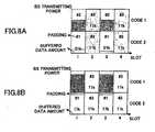
mobile station # 1 requires padding of 36 kbits, which equals 51 kbits minus 15 kbits (51-15=36). Thus,mobile station # 1 requires a large amount of padding.Mobile station # 2 requires padding of 26 kbits, which equals 51 kbits minus 25 kbits (51-25=26). This means that a large portion of transmitting power of the base station (BS) is wasted for padding, which does not bear effective information, when transmitting packets tomobile stations # 1 and #2, as illustrated inFIG. 8A . - In contrast, the sender (for example, the base station) determines the modulation and coding set based not only on the channel quality (CQI), but also on the amount of data buffered in the transmission buffer, according to the present invention. Consequently, a lower-rate modulation and coding set is selected for
mobile station # 1, in place of 64QAM3/4 corresponding toCQI level 5. To be more precise, a modulation and coding set of QPAK3/4 is selected, corresponding to the transmission block size (TBS) of 17 kbits, which is greater than the buffered data amount (15 kbits) and has the minimum gap from the buffered data amount. Formobile station # 2, a lower-rate modulation and coding set is selected, in place of 64QAM3/4 corresponding toCQI level 5. To be more precise, a modulation and coding set of 16QAM3/4 is selected, corresponding to the transmission block size (TBS) of 34 kbits, which is greater than the buffered data amount (25 kbits) and has the minimum gap from the buffered data amount. - With this arrangement, padding at
mobile station # 1 becomes only 2 kbits, which equals 17 kbits minus 15 kbits (17-15=2). Atmobile station # 2, only 9 kbits of padding is required, which equals 34 kbits minus 25 kbits (34-25=9). In this manner, the amount of padding can be reduced greatly, as compared with the conventional technique. Consequently, the transmitting power of the sender (e.g., the base station) wasted for the padding contained in the packets transmitted to themobile stations # 1 and #2, can be reduced, as illustrated inFIG. 8B . - As has been described above, either the base station or the mobile station, which is a sender of a packet, determines a modulation and coding set that satisfies a prescribed transmission condition corresponding to the channel quality; and makes padding, which is added to the data buffered in the transmission buffer when the buffered data amount is less than the transmission block size, become the minimum, based on the channel quality in the packet transmission direction and the amount of buffered data. With this arrangement, if the channel quality is good, and if the amount of buffered data in the transmission buffer is small, a low-rate modulation and coding set is employed. Consequently, the amount of padding added to the data to be transmitted can be reduced, and at the same time, QoS and the protection against interference can be improved.
Claims (3)
- A packet communications method for carrying out packet communications between a base station (100) and a mobile station (200) located in an area controlled by the base station, the method comprising:detecting (120) a channel quality between the base station and the mobile station;detecting (130) the amount of data buffered in a transmission buffer (140) of a sender; anddetermining (150) a corresponding modulation scheme and transmission unit size to be used in the packet communications based on the channel quality, wherein, when the buffered data amount is smaller than the transmission unit size, the transmission unit size and the modulation scheme are determined such that the transmission unit size is at or above the buffered data amount so that the transmission unit size has a minimum transmission gap between the determined transmission unit size filled with padding bits, and the buffered data amount.
- A base station (100) arranged to carry out packet communications with a mobile station (200) located in an area controlled by the base station, the base station comprising:a channel quality detecting unit (120) arranged to detect a channel quality between the base station and the mobile station;a buffered data monitoring unit (130) arranged to monitor the amount of data buffered in a transmission buffer (140) of the base station; anda modulation scheme determination unit (150) arranged to determine a corresponding modulation scheme and transmission unit size to be used in the packet communications based on the channel quality, wherein, when the buffered data amount is smaller than the transmission unit size, the transmission unit size and the modulation scheme are determined such that the transmission unit size is at or above the buffered data amount so that the transmission unit size has a minimum transmission gap between the determined transmission unit size filled with padding bits, and the buffered data amount.
- A mobile station (200) arranged to carry out packet communication with a base station (100), comprising:a channel quality detecting unit (220) arranged to detect a channel quality between the base station and the mobile station;a buffered data monitoring unit arranged to monitor the amount of data buffered in a transmission buffer of the mobile station; anda modulation scheme determination unit arranged to determine a corresponding modulation scheme and transmission unit size to be used in the packet communications based on the channel quality, wherein, when the buffered data amount is smaller than the transmission unit size, the transmission unit size and the modulation scheme are determined such that the transmission unit size is at or above the buffered data amount so that the transmission unit size has a minimum transmission gap between the determined transmission unit size filled with padding bits, and the buffered data amount.
Applications Claiming Priority (2)
| Application Number | Priority Date | Filing Date | Title |
|---|---|---|---|
| JP2002365563 | 2002-12-17 | ||
| JP2002365563AJP4015939B2 (en) | 2002-12-17 | 2002-12-17 | Packet communication method, base station, mobile station, and packet communication program |
Publications (3)
| Publication Number | Publication Date |
|---|---|
| EP1432166A2 EP1432166A2 (en) | 2004-06-23 |
| EP1432166A3 EP1432166A3 (en) | 2006-09-27 |
| EP1432166B1true EP1432166B1 (en) | 2010-11-24 |
Family
ID=32376247
Family Applications (1)
| Application Number | Title | Priority Date | Filing Date |
|---|---|---|---|
| EP20030257892Expired - LifetimeEP1432166B1 (en) | 2002-12-17 | 2003-12-16 | Data packet communications taking into account channel quality and buffered data amount |
Country Status (5)
| Country | Link |
|---|---|
| US (1) | US7821982B2 (en) |
| EP (1) | EP1432166B1 (en) |
| JP (1) | JP4015939B2 (en) |
| CN (1) | CN1266899C (en) |
| DE (1) | DE60335072D1 (en) |
Families Citing this family (61)
| Publication number | Priority date | Publication date | Assignee | Title |
|---|---|---|---|---|
| US7418236B2 (en)* | 2004-04-20 | 2008-08-26 | Mobile Satellite Ventures, Lp | Extraterrestrial communications systems and methods including ancillary extraterrestrial components |
| US8655398B2 (en) | 2004-03-08 | 2014-02-18 | Atc Technologies, Llc | Communications systems and methods including emission detection |
| JP4510006B2 (en) | 2004-04-30 | 2010-07-21 | 三菱電機株式会社 | Mobile station, base station, communication system, data amount information transmission method, transmission control information notification method, and wireless communication method |
| US7584397B2 (en) | 2004-06-10 | 2009-09-01 | Interdigital Technology Corporation | Method and apparatus for dynamically adjusting data transmission parameters and controlling H-ARQ processes |
| JP2006115358A (en)* | 2004-10-15 | 2006-04-27 | Ntt Docomo Inc | Packet transmission control apparatus and packet transmission control method |
| EP2490494B1 (en)* | 2004-10-20 | 2016-05-11 | Qualcomm Incorporated | Multiple Frequency Band Operation in Wireless Networks |
| US20080056182A1 (en)* | 2004-11-09 | 2008-03-06 | Ntt Docomo Inc. | Mobile Communication System, Mobile Station, Wireless Base Station, and Wireless Line Control Station |
| JP4457868B2 (en)* | 2004-11-25 | 2010-04-28 | 富士通株式会社 | Wireless communication device, mobile station |
| WO2006065181A1 (en)* | 2004-12-17 | 2006-06-22 | Telefonaktiebolaget L M Ericsson (Publ) | Apparatus and method in a cellular network |
| US8189615B2 (en) | 2004-12-23 | 2012-05-29 | Nokia Corporation | Method and apparatus for communicating scheduling information from a UE to a radio access network |
| JP4956429B2 (en)* | 2005-07-28 | 2012-06-20 | 富士通株式会社 | Wireless transmission device and downlink transmission control method in the same |
| JP4706755B2 (en)* | 2006-03-29 | 2011-06-22 | 日本電気株式会社 | Base station apparatus and data retransmission method thereof |
| KR100946902B1 (en)* | 2006-05-06 | 2010-03-09 | 삼성전자주식회사 | Resource management apparatus and method in mobile communication system |
| JP4781923B2 (en)* | 2006-06-28 | 2011-09-28 | 京セラ株式会社 | Wireless communication apparatus and wireless communication method |
| BRPI0717823A2 (en)* | 2006-10-03 | 2014-04-15 | Panasonic Corp | RETRANSMITTER STATION IN MOBILE COMMUNICATION SYSTEM AND AUTOMATIC RETRANSMISSION CHANNEL ADJUSTMENT METHOD |
| US20090323641A1 (en)* | 2006-11-10 | 2009-12-31 | Panasonic Corporation | Radio communication mobile station device and mcs selection method |
| GB2452697A (en) | 2007-08-14 | 2009-03-18 | Nec Corp | Dynamically allocating new resources to a node provided with persistently allocated resources |
| JP5052258B2 (en)* | 2007-08-15 | 2012-10-17 | 株式会社エヌ・ティ・ティ・ドコモ | Mobile communication system, mobile station and radio base station |
| GB0716028D0 (en)* | 2007-08-16 | 2007-09-26 | Fujitsu Ltd | Communication systems |
| US20090161613A1 (en)* | 2007-11-30 | 2009-06-25 | Mark Kent | Method and system for constructing channel quality indicator tables for feedback in a communication system |
| JP2009206627A (en)* | 2008-02-26 | 2009-09-10 | Kyocera Corp | Wireless communication system, mobile station, base station and wireless communication method |
| WO2009131502A1 (en)* | 2008-04-24 | 2009-10-29 | Telefonaktiebolaget L M Ericsson (Publ) | Error rate management |
| US8971241B2 (en)* | 2008-09-30 | 2015-03-03 | Qualcolmm Incorporated | Techniques for supporting relay operation in wireless communication systems |
| US9203564B2 (en)* | 2008-10-20 | 2015-12-01 | Qualcomm Incorporated | Data transmission via a relay station in a wireless communication system |
| US8638732B2 (en)* | 2009-01-07 | 2014-01-28 | Samsung Electronics Co., Ltd. | Apparatus and method for allocating resources using codebook in a broadband wireless communication system |
| JP5206871B2 (en)* | 2009-05-15 | 2013-06-12 | 富士通株式会社 | Modulation method switching method, transmitting station and receiving station |
| US9706599B1 (en) | 2009-07-23 | 2017-07-11 | Marvell International Ltd. | Long wireless local area network (WLAN) packets with midambles |
| KR101657255B1 (en) | 2009-07-29 | 2016-09-13 | 마벨 월드 트레이드 리미티드 | Methods and apparatus for wlan transmission |
| KR101563747B1 (en)* | 2009-08-19 | 2015-10-27 | 삼성전자주식회사 | Method and apparatus for generating adaptive channel quality information in a wireless communication system |
| JP4998541B2 (en)* | 2009-12-16 | 2012-08-15 | 富士通株式会社 | Wireless communication device, mobile station |
| US9178648B2 (en)* | 2010-01-06 | 2015-11-03 | Alcatel Lucent | Method to improve voice over IP capacity for user equipment employing variable rate vocoders |
| KR101656291B1 (en)* | 2010-05-03 | 2016-09-22 | 삼성전자주식회사 | Apparatus and method for improving transmission efficiency in wireless communication system |
| JP5445611B2 (en)* | 2012-03-30 | 2014-03-19 | 富士通株式会社 | Wireless communication method |
| US9185661B2 (en)* | 2012-06-04 | 2015-11-10 | Nokia Solutions And Networks Oy | Performing power control based on nominal packet size |
| EP2870815A4 (en)* | 2012-07-03 | 2016-06-22 | Nokia Technologies Oy | Methods and apparatus for contention based transmission |
| JP5744809B2 (en)* | 2012-09-05 | 2015-07-08 | 株式会社Nttドコモ | Mobile communication method, radio base station, and mobile station |
| US9869432B2 (en) | 2013-01-30 | 2018-01-16 | Cree, Inc. | Luminaires using waveguide bodies and optical elements |
| US9366396B2 (en) | 2013-01-30 | 2016-06-14 | Cree, Inc. | Optical waveguide and lamp including same |
| US9519095B2 (en) | 2013-01-30 | 2016-12-13 | Cree, Inc. | Optical waveguides |
| US9291320B2 (en) | 2013-01-30 | 2016-03-22 | Cree, Inc. | Consolidated troffer |
| US9690029B2 (en) | 2013-01-30 | 2017-06-27 | Cree, Inc. | Optical waveguides and luminaires incorporating same |
| US9442243B2 (en) | 2013-01-30 | 2016-09-13 | Cree, Inc. | Waveguide bodies including redirection features and methods of producing same |
| US9625638B2 (en) | 2013-03-15 | 2017-04-18 | Cree, Inc. | Optical waveguide body |
| US20140243037A1 (en)* | 2013-02-26 | 2014-08-28 | Qualcomm Incorporated | Transmitting power optimization on a wireless communication device |
| US9798072B2 (en) | 2013-03-15 | 2017-10-24 | Cree, Inc. | Optical element and method of forming an optical element |
| US9920901B2 (en) | 2013-03-15 | 2018-03-20 | Cree, Inc. | LED lensing arrangement |
| US10436970B2 (en) | 2013-03-15 | 2019-10-08 | Ideal Industries Lighting Llc | Shaped optical waveguide bodies |
| US10400984B2 (en) | 2013-03-15 | 2019-09-03 | Cree, Inc. | LED light fixture and unitary optic member therefor |
| US9366799B2 (en) | 2013-03-15 | 2016-06-14 | Cree, Inc. | Optical waveguide bodies and luminaires utilizing same |
| US10379278B2 (en)* | 2013-03-15 | 2019-08-13 | Ideal Industries Lighting Llc | Outdoor and/or enclosed structure LED luminaire outdoor and/or enclosed structure LED luminaire having outward illumination |
| US10502899B2 (en)* | 2013-03-15 | 2019-12-10 | Ideal Industries Lighting Llc | Outdoor and/or enclosed structure LED luminaire |
| US10209429B2 (en) | 2013-03-15 | 2019-02-19 | Cree, Inc. | Luminaire with selectable luminous intensity pattern |
| CN104065446A (en)* | 2013-03-21 | 2014-09-24 | 上海贝尔股份有限公司 | Method for signaling sending and receiving MCS |
| CN103888223B (en)* | 2014-04-01 | 2019-01-08 | 中国科学院微电子研究所 | Modulation control method and device |
| EP3149879B1 (en) | 2014-06-02 | 2018-05-23 | Marvell World Trade Ltd. | High efficiency orthogonal frequency division multiplexing (ofdm) physical layer (phy) |
| JP6699911B2 (en) | 2014-06-11 | 2020-05-27 | マーベル ワールド トレード リミテッド | Compressed preamble for wireless communication system |
| US11719882B2 (en) | 2016-05-06 | 2023-08-08 | Ideal Industries Lighting Llc | Waveguide-based light sources with dynamic beam shaping |
| US10416377B2 (en) | 2016-05-06 | 2019-09-17 | Cree, Inc. | Luminaire with controllable light emission |
| US10541796B2 (en) | 2017-06-09 | 2020-01-21 | Marvell World Trade Ltd. | Packets with midambles having compressed OFDM symbols |
| WO2019060407A1 (en) | 2017-09-22 | 2019-03-28 | Marvell World Trade Ltd. | Determining number of midambles in a packet |
| US11592984B2 (en)* | 2020-09-11 | 2023-02-28 | Seagate Technology Llc | Onboard machine learning for storage device |
Citations (2)
| Publication number | Priority date | Publication date | Assignee | Title |
|---|---|---|---|---|
| WO2002041647A2 (en)* | 2000-11-17 | 2002-05-23 | Nokia Corporation | Apparatus, and method for communicating packet data in a sdma (space-division, multiple-access) communication scheme |
| EP1249951A1 (en)* | 2000-11-16 | 2002-10-16 | Sony Corporation | Information processing apparatus and communication apparatus |
Family Cites Families (10)
| Publication number | Priority date | Publication date | Assignee | Title |
|---|---|---|---|---|
| JPH09312649A (en) | 1996-05-21 | 1997-12-02 | Nec Corp | Transmission rate automatic switching method |
| US6167031A (en)* | 1997-08-29 | 2000-12-26 | Telefonaktiebolaget Lm Ericsson (Publ) | Method for selecting a combination of modulation and channel coding schemes in a digital communication system |
| GB2343342A (en)* | 1998-10-28 | 2000-05-03 | Int Mobile Satellite Org | Satellite communication system with variable data transmission rate |
| GB9900126D0 (en)* | 1999-01-06 | 1999-02-24 | Univ Southampton | Wideband burst-by-burst adaptive H.263 assisted wireless video telephony |
| US6330288B1 (en) | 1999-01-28 | 2001-12-11 | Lucent Technologies Inc. | Coding/modulation scheme selection technique |
| US6754189B1 (en) | 1999-04-08 | 2004-06-22 | Lucent Technologies Inc. | Method of queue length based burst management in wireless communication systems |
| US6701129B1 (en)* | 2000-09-27 | 2004-03-02 | Nortel Networks Limited | Receiver based adaptive modulation scheme |
| JP3737353B2 (en) | 2000-09-28 | 2006-01-18 | 株式会社エヌ・ティ・ティ・ドコモ | COMMUNICATION DEVICE AND COMMUNICATION LINE ALLOCATION METHOD |
| JP2003234696A (en)* | 2002-02-06 | 2003-08-22 | Mitsubishi Electric Corp | Transmission power correction method, mobile communication system and mobile station |
| US7293217B2 (en)* | 2002-12-16 | 2007-11-06 | Interdigital Technology Corporation | Detection, avoidance and/or correction of problematic puncturing patterns in parity bit streams used when implementing turbo codes |
- 2002
- 2002-12-17JPJP2002365563Apatent/JP4015939B2/ennot_activeExpired - Fee Related
- 2003
- 2003-12-16EPEP20030257892patent/EP1432166B1/ennot_activeExpired - Lifetime
- 2003-12-16DEDE60335072Tpatent/DE60335072D1/ennot_activeExpired - Lifetime
- 2003-12-17USUS10/736,698patent/US7821982B2/ennot_activeExpired - Fee Related
- 2003-12-17CNCNB2003101214654Apatent/CN1266899C/ennot_activeExpired - Fee Related
Patent Citations (2)
| Publication number | Priority date | Publication date | Assignee | Title |
|---|---|---|---|---|
| EP1249951A1 (en)* | 2000-11-16 | 2002-10-16 | Sony Corporation | Information processing apparatus and communication apparatus |
| WO2002041647A2 (en)* | 2000-11-17 | 2002-05-23 | Nokia Corporation | Apparatus, and method for communicating packet data in a sdma (space-division, multiple-access) communication scheme |
Also Published As
| Publication number | Publication date |
|---|---|
| JP2004200923A (en) | 2004-07-15 |
| EP1432166A2 (en) | 2004-06-23 |
| EP1432166A3 (en) | 2006-09-27 |
| JP4015939B2 (en) | 2007-11-28 |
| US7821982B2 (en) | 2010-10-26 |
| DE60335072D1 (en) | 2011-01-05 |
| CN1509028A (en) | 2004-06-30 |
| CN1266899C (en) | 2006-07-26 |
| US20040184417A1 (en) | 2004-09-23 |
Similar Documents
| Publication | Publication Date | Title |
|---|---|---|
| EP1432166B1 (en) | Data packet communications taking into account channel quality and buffered data amount | |
| US7761113B2 (en) | Communication terminal apparatus and base station apparatus | |
| US9674798B2 (en) | Transport format combination selecting method, wireless communication system, and mobile station | |
| JP5060885B2 (en) | Mobile communication system and communication control method | |
| US7444162B2 (en) | Apparatus and a method for distributing a transmission power in a cellular communications network | |
| US7426385B2 (en) | Communication device and method for communicating over a digital mobile network | |
| EP2078388B1 (en) | Method and arrangement for transmitting cqi on the uplink | |
| EP1956728B1 (en) | Method for controlling communication of radio terminal, and radio terminal | |
| US20070259671A1 (en) | Generation, Deployment and Use of Tailored Channel Quality Indicator Tables | |
| EP2066058A2 (en) | Method and system for constructing channel quality indicator tables for feedback in a communication system | |
| US20090305715A1 (en) | Channel quality reporting in a wireless communication system | |
| EP1796331B1 (en) | Apparatus and method for call admission control | |
| KR100339740B1 (en) | Buffer State Report Message And Method Of Making Report Buffer State To Access Network In High Data Rate System | |
| US7486956B2 (en) | Channel estimation and channel quality indicator (CQI) measurements for a high-speed downlink GPRS | |
| US7330700B2 (en) | Radio apparatus and method for determining the communication timing of a channel quality indicator (CQI) based on CQI update and CQI repetition count information | |
| EP1810436A1 (en) | A method for improving an hs-dsch transport format allocation | |
| WO2007148707A1 (en) | Base station and method | |
| EP1807943B1 (en) | Radio quality based channel resource management | |
| JP4929280B2 (en) | Base station, user equipment and method | |
| EP1875628B1 (en) | Method and arrangement for allocating power in a communication network | |
| EP1825629B1 (en) | Power step control for high-speed downlink shared channel packet access | |
| CN100420336C (en) | A Scheduling Method for Non-real-time Services | |
| EP1947887B1 (en) | A transport format resource combination (TFRC) selection method |
Legal Events
| Date | Code | Title | Description |
|---|---|---|---|
| PUAI | Public reference made under article 153(3) epc to a published international application that has entered the european phase | Free format text:ORIGINAL CODE: 0009012 | |
| 17P | Request for examination filed | Effective date:20040107 | |
| AK | Designated contracting states | Kind code of ref document:A2 Designated state(s):AT BE BG CH CY CZ DE DK EE ES FI FR GB GR HU IE IT LI LU MC NL PT RO SE SI SK TR | |
| AX | Request for extension of the european patent | Extension state:AL LT LV MK | |
| PUAL | Search report despatched | Free format text:ORIGINAL CODE: 0009013 | |
| AK | Designated contracting states | Kind code of ref document:A3 Designated state(s):AT BE BG CH CY CZ DE DK EE ES FI FR GB GR HU IE IT LI LU MC NL PT RO SE SI SK TR | |
| AX | Request for extension of the european patent | Extension state:AL LT LV MK | |
| AKX | Designation fees paid | Designated state(s):DE GB | |
| 17Q | First examination report despatched | Effective date:20071102 | |
| GRAP | Despatch of communication of intention to grant a patent | Free format text:ORIGINAL CODE: EPIDOSNIGR1 | |
| GRAS | Grant fee paid | Free format text:ORIGINAL CODE: EPIDOSNIGR3 | |
| GRAA | (expected) grant | Free format text:ORIGINAL CODE: 0009210 | |
| AK | Designated contracting states | Kind code of ref document:B1 Designated state(s):DE GB | |
| REG | Reference to a national code | Ref country code:GB Ref legal event code:FG4D | |
| REF | Corresponds to: | Ref document number:60335072 Country of ref document:DE Date of ref document:20110105 Kind code of ref document:P | |
| PLBE | No opposition filed within time limit | Free format text:ORIGINAL CODE: 0009261 | |
| STAA | Information on the status of an ep patent application or granted ep patent | Free format text:STATUS: NO OPPOSITION FILED WITHIN TIME LIMIT | |
| 26N | No opposition filed | Effective date:20110825 | |
| REG | Reference to a national code | Ref country code:DE Ref legal event code:R097 Ref document number:60335072 Country of ref document:DE Effective date:20110825 | |
| PGFP | Annual fee paid to national office [announced via postgrant information from national office to epo] | Ref country code:DE Payment date:20181204 Year of fee payment:16 | |
| PGFP | Annual fee paid to national office [announced via postgrant information from national office to epo] | Ref country code:GB Payment date:20181212 Year of fee payment:16 | |
| REG | Reference to a national code | Ref country code:DE Ref legal event code:R119 Ref document number:60335072 Country of ref document:DE | |
| GBPC | Gb: european patent ceased through non-payment of renewal fee | Effective date:20191216 | |
| PG25 | Lapsed in a contracting state [announced via postgrant information from national office to epo] | Ref country code:DE Free format text:LAPSE BECAUSE OF NON-PAYMENT OF DUE FEES Effective date:20200701 Ref country code:GB Free format text:LAPSE BECAUSE OF NON-PAYMENT OF DUE FEES Effective date:20191216 |