EP1431758A1 - Measurement instrument and concentration measurement apparatus - Google Patents
Measurement instrument and concentration measurement apparatusDownload PDFInfo
- Publication number
- EP1431758A1 EP1431758A1EP02772957AEP02772957AEP1431758A1EP 1431758 A1EP1431758 A1EP 1431758A1EP 02772957 AEP02772957 AEP 02772957AEP 02772957 AEP02772957 AEP 02772957AEP 1431758 A1EP1431758 A1EP 1431758A1
- Authority
- EP
- European Patent Office
- Prior art keywords
- attribute information
- measurement
- output section
- measuring device
- information output
- Prior art date
- Legal status (The legal status is an assumption and is not a legal conclusion. Google has not performed a legal analysis and makes no representation as to the accuracy of the status listed.)
- Granted
Links
Images


Classifications
- G—PHYSICS
- G01—MEASURING; TESTING
- G01N—INVESTIGATING OR ANALYSING MATERIALS BY DETERMINING THEIR CHEMICAL OR PHYSICAL PROPERTIES
- G01N33/00—Investigating or analysing materials by specific methods not covered by groups G01N1/00 - G01N31/00
- G01N33/48—Biological material, e.g. blood, urine; Haemocytometers
- G01N33/483—Physical analysis of biological material
- G01N33/487—Physical analysis of biological material of liquid biological material
- G01N33/4875—Details of handling test elements, e.g. dispensing or storage, not specific to a particular test method
- G01N33/48771—Coding of information, e.g. calibration data, lot number
- G—PHYSICS
- G01—MEASURING; TESTING
- G01N—INVESTIGATING OR ANALYSING MATERIALS BY DETERMINING THEIR CHEMICAL OR PHYSICAL PROPERTIES
- G01N35/00—Automatic analysis not limited to methods or materials provided for in any single one of groups G01N1/00 - G01N33/00; Handling materials therefor
- G01N35/00029—Automatic analysis not limited to methods or materials provided for in any single one of groups G01N1/00 - G01N33/00; Handling materials therefor provided with flat sample substrates, e.g. slides
- G01N2035/00089—Magazines
- G—PHYSICS
- G01—MEASURING; TESTING
- G01N—INVESTIGATING OR ANALYSING MATERIALS BY DETERMINING THEIR CHEMICAL OR PHYSICAL PROPERTIES
- G01N35/00—Automatic analysis not limited to methods or materials provided for in any single one of groups G01N1/00 - G01N33/00; Handling materials therefor
- G01N35/00584—Control arrangements for automatic analysers
- G01N35/00594—Quality control, including calibration or testing of components of the analyser
- G01N35/00693—Calibration
- G—PHYSICS
- G01—MEASURING; TESTING
- G01N—INVESTIGATING OR ANALYSING MATERIALS BY DETERMINING THEIR CHEMICAL OR PHYSICAL PROPERTIES
- G01N35/00—Automatic analysis not limited to methods or materials provided for in any single one of groups G01N1/00 - G01N33/00; Handling materials therefor
- G01N35/00584—Control arrangements for automatic analysers
- G01N35/00722—Communications; Identification
- G01N35/00732—Identification of carriers, materials or components in automatic analysers
Definitions
- the present inventionrelates to a measurement instrument such as a biosensor, a method of making the measurement instrument, a set of the measurement instrument and a measurement auxiliary instrument, a sensor cartridge for accommodating a plurality of the measurement instruments, and a concentration measuring device for calculating the concentration of a specific component in a sample liquid with the measurement instrument.
- a measurement instrumentsuch as a biosensor
- a method of making the measurement instrumenta set of the measurement instrument and a measurement auxiliary instrument
- a sensor cartridgefor accommodating a plurality of the measurement instruments
- a concentration measuring devicefor calculating the concentration of a specific component in a sample liquid with the measurement instrument.
- redox reactionIn measuring a specific component in body fluid (e.g. glucose in blood), redox reaction is utilized in general.
- a handy-size blood measuring deviceis generally used for the easy measurement of blood sugar at or away from home.
- a disposal biosensor for providing an enzyme reaction fieldis attached to this simple blood sugar measuring device.
- the biosensormeasures blood sugar level in blood (see JP-B-H08-10208 for example).
- the biosensorsmay be different in sensitivity. Such difference is often made by change in component materials or in design for production lines. Particularly on launching the production lines, optimization in production conditions and material selection may cause the biosensors to differ in sensitivity. Further, when the production of the biosensors is performed at a plurality of factories or one factory but on the plural production lines, the biosensors produced at the different factories or on the different lines may also differ in sensitivity. Therefore, the blood sugar measuring device is often provided in advance with a plurality of calibration curves to measure concentrations correctly with the biosensors varying in sensitivity. With the blood sugar measuring device capable of measuring a plurality of measurement items such as a blood sugar level and a cholesterol level, the plural calibration curves are needed for the measurement items. In these cases, the measuring device must recognize information about a calibration curve suitable for the sensitivity of the biosensor and the measurement items to select such a calibration curve.
- each calibration curveis assigned with an identification code in advance.
- the biosensoris also assigned with an identification code, which is displayed on a case of the biosensor or in a user instruction.
- the blood sugar measuring deviceis installed with a program for determining the calibration curve in advance. When a user operates a button in the blood sugar measuring device, the calibration curve is determined.
- the caseaccommodates the plural biosensors and a correction chip for outputting information about the calibration curve suited to the biosensor.
- the concentration measuring devicedetermines the calibration curve automatically (see e.g. JP-A-H08-20412).
- the operationis a burden to the user. Further, he or she may forget to perform the operation. Similarly, the use of the correction chip is a burden to the user, and he or she may forget to determine the calibration curve. If the user forgets the determination of the calibration curve, the measurement of blood sugar level cannot be performed appropriately. This is because the determination of the calibration curve should not be entrusted to the user.
- the correction chipincreases the production cost since it requires additional production lines besides the production lines for the biosensor.
- the biosensorutilizes various enzymes. In measuring the blood sugar level of the same sample blood, using different enzymes produces different calculation results of the blood sugar level.
- the enzymemay be hexokinase or glucose oxidase, while the sample blood may be whole blood or plasma.
- the blood sugar level measured with glucose oxidaseis not appropriate for determining whether or not a patient develops diabetes. Further, when the blood sugar measuring device calculates the blood sugar level with the biosensor utilizing hexokinase, the blood sugar level is not correctly calculated with the biosensor utilizing glucose oxidase.
- the concentration measuring deviceis made to be capable of selecting a calibration curve suitable for the measuring instrument.
- the present inventionprevents incorrect concentration measurement due to the difference between the measurement standard of the measurement instrument and that of the concentration measuring device.
- a measurement instrumentused as an attachment to a concentration measuring device for calculating a concentration based on concentration measurement information, and outputting the concentration measurement information to the concentration measuring device.
- An attribute information output sectionis formed to output information about attributes of the measurement instrument as electric physical values.
- the attribute informationis based on at least one of the conditions including a resistance of the attribute information output section, a location of the attribute information output section, and the size of a region on which the attribute information output section is formed.
- the attribute informationis utilized for enabling the concentration measuring device to select a calibration curve suitable for the measurement instrument. More specifically, the attribute information is used to select a calibration curve suitable for the sensitivity of the measurement instrument or to select a calibration curve suitable for preset measurement items in the measurement instrument.
- the attribute informationmay be about a measurement standard applied to the measurement instrument.
- the attribute informationmay include the production data of the measurement instrument, the validity data, the manufacturer, the production site (e.g. the country of manufacture and the factory location), the identification number of the lot that includes the measurement instrument (the lot number).
- the measurement standardis determinedby the kind of enzyme and the sample state (e.g., whole blood or plasma) in the measuring instrument, whereas the standard is determined by the method of calculation in the concentration measuring device.
- the attribute information output sectionmay include a plurality of individual information output sections for outputting specific information as electric physical values.
- the electric physical valueis electric current, resistance, voltage, etc.
- the attribute information or individual informationis identified by the amount of the electric physical value, the existence of the electric physical value (open-short signal) or the combination of them. More specifically, when the attribute information is provided based on the resistance of the attribute information output section, the content of the attribute information is represented by the magnitude of the electric physical value, for example.
- the attribute informationis provided based on the location of the attribute information output section, it is outputted by at least one of the open-short signal and the amount of the electric physical value for example.
- the attribute informationis provided based an amount of space formed with the attribute information output section, it is outputted by at least one of the open-short signal and the amount of the electric physical value for example.
- the resistanceis adjusted by varying length, thickness or width, or by selecting material for the attribute information output section.
- the measurement instrument of the present inventionfurther comprises a substrate at least including an end portion inserted into the concentration measuring device for the concentration measurement.
- the attribute information output sectionis a strip formed in the end portion and having a width of 2 mm and below.
- the measurement instrumentfurther comprises a substrate having an end portion inserted into the concentration measuring device for concentration measurement for example, and a calculation information output section formed on the endportion to output information for concentration calculation.
- the attribute information output sectionis formed between the calculation information output section and an inserting edge of the end portion of the substrate into the concentration measuring device.
- the attribute information output sectionincludes first and second portions to contact terminals of the concentration measuring device and one or a plurality of connection-breakable parts connecting the first and second portions.
- the attribute information output sectionis provided with the attribute information by selectively breaking or leaving intact at least one of the connection-breakable parts.
- the measurement instrument of the present inventioncomprises a correction information output section for outputting correction information relating to the discrepancy between the actual resistance in the attribute information output section and a resistance preset in the attribute information output section.
- the attribute information output sectionoutputs identification information for informing the concentration measuring device that the measurement instrument can output the information for concentration calculation.
- a method of making the measurement instrumentincluding a step of forming an attribute information output section for outputting attribute information about attributes of a measurement instrument.
- the stepcomprises a first operation for forming first and second portions contacting terminals of the concentration measuring device and one or plurality of connection-breakable parts connecting the first and second portions, and a second operation for disconnecting one or plurality of connection-breakable parts selected from the connection-breakable parts.
- the first stepmay be performed by applying a conductive material or a resistance material by screen printing.
- the second stepmay be performed by drill machining, laser processing or etching.
- a measurement instrumentused as an attachment to a concentration measuring device for calculating a concentration based on concentration measurement information, and outputting the concentration measurement information to the concentration measuring device.
- the measurement instrumentincludes a measurement standard information output section to output information about a measurement standard applied to the measurement instrument.
- a setcomprising a measurement instrument and a measurement auxiliary instrument.
- the measurement instrumentis used as an attachment to a concentration measuring device and outputting the concentration calculation information to the concentration measuring device.
- the measurement auxiliary instrumentis used as an attachment to a concentration measuring device and formed with a measurement standard information output section for outputting the measurement standard information about a measurement standard applied to the measurement instrument.
- the measurement auxiliary instrumentis added to each lot including a plurality of measurement instruments and is used as an attachment to the concentration measuring device for enabling the concentration measuring device to recognize the characteristics of the measurement instruments.
- the measurement standard informationis supplied in the same way as in the first aspect of the present invention utilizing the attribute information output section.
- the attribute informationis provided based on at least one of a resistance of the attribute information output section, a location of the attribute information output section, and an amount of space formed with the attribute information output section.
- the measurement standardmay be supplied in a different way from the first aspect of the present invention.
- a concentration measuring deviceused with a measurement instrument.
- the measurement instrumenthas an attribute information output section for outputting attribute information about attributes of the measurement instrument.
- the attribute informationis based on at least one of a resistance of the attribute information output section, a location of the attribute information output section, and the size of a region on which the attribute information output section is formed.
- the concentration measuring devicecomprises a recognizer for recognizing or detecting the attribute information, and performs a specific operation relating to a concentration measurement based on the attribute information recognized by the recognizer.
- the measurement instrumentincludes the attribute information output section for outputting the attribute information as calibration curve determination information for selecting a calibration curve suitable for the measurement instrument.
- the concentration measuring devicecomprises a storage unit for storing information about a plurality of calibration curves, a calibration curve selection unit selecting a specific calibration curve suitable for the measurement instrument from the calibration curves based on the attribute information for example.
- the determination of the calibration curvemay depend on the sensitivity or the preset measurement items (e.g. for glucose measurement or cholesterol measurement) of the measurement instrument.
- the attribute information output sectionmay output the attribute information as measurement standard information about a measurement standard applied to the measurement instrument.
- the concentration measuring devicecomprises a judging unit determining whether or not to perform concentration measurement with the measurement instrument based on the attribute information.
- the attribute information output sectionmay be output the attribute information including the production date, the validity date, the manufacturer, the production site (e.g. country of manufacture and factory location), an identification number of the lot including the measurement instrument (lot number).
- the recognition meanshas a plurality of terminals contacting the attribute information output section, recognizing the attribute information in applying a constant voltage or current to the attribute information output section via the terminals.
- a sensor cartridgehaving a plurality of measurement instruments for outputting concentration measurement information relating to a concentration of a specific component in a sample liquid, the cartridge being used as an attachment to a concentration measuring device for calculating the concentration of the specific component based on concentration measurement information.
- the sensor cartridgecomprises an attribute information output section for outputting attribute information about attributes of the measurement instruments.
- the attribute informationis based on at least one of conditions including a resistance of the attribute information output section, a location of the attribute information output section, and the size of a region on which the attribute information output section is formed.
- Other structuresmay be used to output the attribute information.
- the attribute informationis used to select a calibration curve suitable for the measurement instruments depending on the sensitivity or the preset measurement items of the measurement instruments.
- the attribute informationmay include a measurement standard applied to the measurement instruments, the production date, the validity date, the manufacturer, the production site (e.g. country of manufacture and factory location), an identification number of the lot including the measurement instruments (lot number).
- a concentration measuring devicewith a sensor cartridge accommodating a plurality of measurement instruments, performing concentration calculation based on concentration measurement information from the measurement instrument taken out of the sensor cartridge having an attribute information output section for outputting attribute information about attributes of the measurement instruments.
- the concentration measuring devicecomprises a recognizer for recognizing the attribute information, and performs a specific operation relating to a concentration measurement based on the attribute information recognized by the recognition means.
- the attribute information of the measurement instrumentis based on at least one of the conditions including a resistance of the attribute information output section, a location of the attribute information output section, and the size of a region on which the attribute information output section is formed.
- the concentration measuring devicecomprises a storage unit storing information about a plurality of calibration curves, and a calibration curve selection unit selecting a specific calibration curve suitable for the measurement instrument from the calibration curves.
- the concentration measuringcomprises a cartridge mount for mounting the sensor cartridge and a plurality of terminals for contacting the attribute information output section.
- the terminalscontact the attribute information output section when the sensor cartridge is being mounted or after the cartridge has been mounted.
- Figs. 1-9show a first embodiment of the present invention.
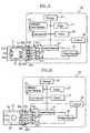
- a concentration measuring device 1 with a biosensor 2 mounted theretois used for calculating the concentration of a specific component in a sample liquid.
- the concentration measuring device 1includes first-sixth terminals 10a-10f, a switch unit 11, a voltage applying unit 12, an electric current measuring unit 13, a storage unit 14, a detection unit 15, a calibration curve selection unit 16, a judging unit 17, a control unit 18 and a calculating unit 19.
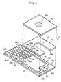
- the biosensor 2includes a cover 20, a spacer 21 and a substrate 22, these members forming a channel 24.
- the channel 24communicates with outside via a hole 20a formed in the cover 20 and an opening 23a of a slit 23 formed in the spacer 21.
- the opening 23aserves as a sample liquid inlet 24a.
- the sample liquid fed via the inlet 24aflows through the channel 24 toward the hole 20a by capillary action.
- the substrate 22, made of resin such as PET,is rectangular.
- the substrate 22has a length of 10-50 mm, a width of 5-20 mm, a thickness 0.5-2 mm for example.
- the substrate 22has an upper surface 22a formed with a working electrode 25, a counterpart electrode 26, a reagent part 27, an attribute information output section 28 and a correction information output section 29.
- the working electrode 25 and the counterpart electrode 26mostly extend longitudinally of the substrate 22, while having ends 25a, 26a extending widthwise of the substrate 22. Thus, the working electrode 25 and the counterpart electrode 26 are L-shaped as a whole.
- the working and counterpart electrodes 25, 26have ends 25b, 26b serving as terminals for contacting the first and sixth terminals 10a and 10f of the measuring device 1 (see Fig. 1).
- the working and counterpart electrodes 25, 26may be formed by screen printing. Specifically, a mask, formed with openings corresponding the working and counterpart electrodes 25, 26, is put on the substrate 22 (normally, on a material substrate in which a plurality of regions for the substrates 22 are set). Then, material ink is supplied to fill the openings and dried. The material ink may be made by dissolving conductive powder and binder resin in a solvent.
- the working and counterpart electrodes 25, 26have a thickness 10-20 ⁇ m, for example.
- the reagent part 27may be a solid element bridging between the end 25a of the working electrode 25 and the end 26a of the counterpart electrode 26.
- the reagent part 27may contain a relatively large amount of mediators (electron carriers) into which a relatively small amount of redox enzymes are dispersed.
- the electron carriermay be a Fe or Ru complex.
- the Fe complexmay be potassium ferricyanide.
- the Ru complexmay have a NH 3 ligand.
- the determination of the redox enzymedepends on the type of the specific component to be measured.
- the specific componentmay be glucose, cholesterol or lactic acid.
- the redox enzymemay be glucose dehydrogenase, glucose oxidase, cholesterol dehydrogenase, cholesterol oxidase, lactic acid dehydrogenase or lactic acid oxidase.
- the attribute information output section 28is used for outputting the attribute information of the biosensor 2.
- the output section 28can output, to the concentration measuring device 1, information such as "calibration curve selection information” to select a calibration curve suitable for the sensitivity of the biosensor 2 and "measurement standard information” regarding the measurement standard adopted for the biosensor 2.
- the output section 28includes first-third leads 28A-28C, and the attribute information is outputted as an electric current (a resistance) when a voltage is applied across the first and second leads 28A, 28B or across the second and third leads 28B, 28C.
- six connection-breakable parts 28a-28fare provided between the adjacent leads 28A-28C. In the present embodiment, two connection-breakable parts are disconnected among the three connection-breakable parts between the adjacent leads.
- the biosensor 2can output information for identifying them. More specifically, the three disconnection patterns between the first and second leads 28A and 28B may correspond to the three predetermined types of measurement standards, while the three disconnection patterns between the second and third leads 28B and 28C may correspond to the three predetermined types of calibration curves. As a result, the three types of the measurement standards and calibration curves can be separately outputted.
- connection-breakable partsare not limited to the illustrated embodiment, but may be otherwise.
- connection-breakable parts to be disconnectedis not limited to the illustrated embodiment. In the case where three connection-breakable parts are set between the adjacent leads, the number of parts to be disconnected may be selected from 0-3. This arrangement allows the desired information to be selected from more pieces of information than where two connection-breakable parts are fixedly disconnected.
- the correction information output section 29corrects the output from the first through third leads 28A-28C.
- the section 29includes a fourth lead 29A and a joint 29B between the fourth lead 29A and the third lead 28C.
- correction informationis outputted as a current (a resistance).
- the concentration measuring device 1may store the resistance preset for the fourth lead 29A. Based on the correction information, it is possible to recognize how much the actually measured resistance of the fourth lead 29A varies from the preset resistance for the fourth lead 29A. Thus, the concentration measuring device 1 can correct the output from the first through third leads 28A-28C based on the deviation of the actual resistance from the preset value.
- the attribute information output section 28 and the correction information output section 29can be formed by screen printing for example.
- the connection-breakable parts 28a-28fare formed to electrically connect the adjacent leads 28A-28C. Thereafter, each of the connection-breakable parts 28a-28f may be disconnected or not in accordancewith a disconnection pattern which is determined based on the measurement standard for the biosensor 2 and the calibration curve (sensitivity of the biosensor 2) used for the concentration calculation.
- the disconnection of the connection-breakable parts 28a-28iis performed by e.g. machining with the use of a drill, laser processing or etching.
- the sensitivity of the biosensor 2may be found by taking an actual measurement of the sensitivity of a given number of biosensors 2 selected from the group of biosensors produced under the same conditions. This is an effective method when the sensitivity of the biosensor 2 is unpredictable due to the possibility of changing in design of production lines or in component materials, for example, at an initial stage of factory production.
- the first through sixth terminals 28a-28f of the concentration measuring device 1contact the ends 25b, 26b of the working and counterpart electrodes 25, 26, the first through third leads 28A-28C of the attribute information output section 28, and the fourth lead 29A of the correction information output section 29 (see Fig. 8A) when the biosensor 2 is attached to the concentration measuring device 1.
- the switch unit 11includes first-sixth analog switches 11a-11f. Each analog switch 11a-11f is separately turned on and off by the control unit 18. By operation of the respective analog switches 11a-11f, each of the terminals 10a-10f is selectively connected to the voltage applying unit 12 or to the electric current measuring unit 13.
- the voltage applying unit 12applies a voltage across the working electrode 25 and the counterpart electrode 26, across the second lead 28B and the first or third lead 28A, 28C, or across the third lead 28C and the fourth lead 29A.
- the voltage applying unit 12comprises a direct-current power supply, such as a dry cell and a rechargeable battery.
- the electric current measuring unit 13measures the electric current flowing through a circuit formed by the voltage applying unit 12 and the biosensor 2.
- the storage unit 14stores data about the calibration curves, the measurement standard of the concentration measuring device 1, and the resistance preset for the fourth lead 29A, for example.
- the detection unit 15detects whether or not the biosensor 2 is attached to the concentration measuring device and whether or not a sample liquid is supplied to the reagent part 27, based on the current measured by the electric current measuring unit 13. Further, the detection unit 15 detects the measurement standard information and calibration curve selection information, based on the attribute information from the attribute information output section 28 and the correction information from the correction information output section 29.
- the calibration curve selection unit 16determines the calibration curve suitable for the sensitivity of the biosensor 2 based on the calibration curve selection information.
- the judging unit 17judges, based on the measurement standard information, whether or not the measurement standard matches that of the concentration measuring device 1.
- the control unit 18controls the operation of the switch unit 11 and the voltage applying unit 12. More specifically, the control unit 18 determines whether or not a voltage need be applied across the working and counterpart electrodes 25, 26 for example, and whether or not a voltage need be applied to desired points in the attribute information output section 28 and the correction information output section 29.
- the calculating unit 19calculates the concentration of the specific component in the sample liquid based on the responsive current measured by the electric current measuring unit 13 and the calibration curve determined by the calibration curve selection unit.
- Each of the storage unit 14, the detection unit 15, the calibration curve selection unit 16, the judging unit 17, the control unit 18 and the calculating unit 19may be constituted by a CPU and a memory such as ROM and RAM. Alternatively, all the units may be constituted by a single common CPU and a plurality of memories connected thereto.
- the detection unit 15first detects whether or not the biosensor 2 is attached to the concentration measuring device 1 (S10). To determine whether or not the biosensor 2 is attached, use is made of a detection sensor such as an optical sensor or a pressure sensor, or of the first through fourth leads 28A-28C, 29A.
- a detection sensorsuch as an optical sensor or a pressure sensor
- the detection unit 15detects that the biosensor 2 is attached to the concentration measuring device 1 (S10: YES), the attribution information of the biosensor is checked (S11).
- the control unit 18directs that the second and third switches 11b, 11c are switched on (S20).
- a voltageis applied across the third and fourth leads 28C, 29A to measure the current flowing at the third and fourth leads 28C, 29A by the electric current measuring unit 13 (S21).
- the detection unit 15determines how much the actual resistance of the fourth lead 29A deviates from the preset resistance, and then calculates a compensation coefficient (S22).
- the control unit 18turns on only the third and fourth analog switches 11c, 11d (S23). Then, a voltage is applied across the second and third leads 28B, 28C, and the current measuring unit 13 measures the current flowing at the second and third leads 28B, 28C (S24). Similarly, as shown in Figs. 7 and 8C, the fourth and fifth analog switches 11d, 11e are turned on by the control unit 18 (S25) for measuring the current flowing at the first and second leads 28A, 28B by the electric current measuring unit 13 (S26).
- the detection portion 15corrects the measured values in S24 and S26 (or the calculated values based on the measured values) according to the compensation coefficient obtained at S22 (S27), and obtains, based on the corrected values, the calibration curve selection information and the measurement standard information (S28).
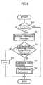
- the judging unit 17determines whether or not the measurement standard of the biosensor 2 is one of the measurable standards for the concentration measurement device 1 (S12). If the concentration measuring device 1 is designed to cope with only one measurement standard, it is determined whether or not the sole measurement standard is the same as that of the biosensor 2.
- the judging unit 17determines that the measurement standard of the biosensor 2 is not compatible with that of the concentration measurement device 1 (S12:NO), error handling is performed (S15). In this case, the concentration measurement with the current biosensor 2 is not performed, and the user is notified of the error by audio or visual means, for example.
- the calibration curve selection unit 16selects, based on the calibration curve selection information, a calibration curve suitable for the biosensor 2 from the calibration curves stored in the storage unit 14 (S:13).
- the concentration measurement processis performed according to the flowchart shown in Fig. 9 (S14).
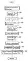
- the detection unit 15detects whether or not the reagent part 27 of the biosensor 2 is supplied with a sample liquid (S30). More specifically, the detection unit 15 compares the measured current by the electric current measuring unit 13 with a predetermined threshold when the first and sixth analog switches 11a, 11f only are turned on as shown in Fig. 8D. If the reagent part 27 is supplied with a sample liquid, the reagent part 27 is dissolved by the sample liquid to form a liquid phase reaction system. In the liquid phase reaction system, the specific component in the sample liquid is oxidized (or deoxidized), while an electron carrier is deoxidized (or oxidized).
- the electric current measuring unit 13can detect that the reagent part 27 undergoes a proper reaction, that is, the reagent part 27 is supplied with the sample liquid, based on the measurement of the oxidation current (or the deoxidation current).
- the determination process of S30is repeated until the supply of a sample liquid is detected (S30:YES).
- an error processingmay be performed if a predetermined period of time has passed after the biosensor 2 is attached, or if the supply of a sample liquid has not been detected after a predetermined number of determinations are performed.
- the detection unit 15determines that the sample liquid is supplied (S30:YES)
- the voltage application to the reagent part 27is stopped (S31).
- the control unit 18turns off the analog switches 11a, 11f based on the information from the detection unit 15.
- control unit 18determines whether or not the predetermined period of time has passed after the voltage application (S32). If the control unit 18 determines that the predetermined period of time has not passed (S32:NO), the determination of S32 is repeated until the unit determines that the predetermined period of time has passed (S32:YES). Since no voltage is applied to the reagent part 27 during the predetermined period of time, the deoxidized (or oxidized) electron carriers accumulate in the reagent part 27.
- control unit 18determines that the predetermined period of time has passed (S32 :YES)
- the control unit 18closes the analog switches 11a, 11f again to apply voltage to the liquid phase reaction system (S33).
- the control unit 18further determines whether or not a predetermined period of time has passed after the voltage application (S:34). If the control unit 18 determines that the predetermined period of time has not passed (S34:NO), the determination of S34 is repeated until the unit determines that the predetermined period of time has passed (S34:YES). Since a voltage is applied to the liquid phase reaction system during the predetermined period of time, the electron carriers are oxidized (or deoxidized). Consequently, the electrons are transferred between the liquid phase reaction system and the working electrode 25, and the electric current measuring unit 13 measures the response current. The response current continues to be measured and monitored by the detection unit 15.
- the calculating unit 19obtains the current response current measured by the electric current measuring unit 13 from the detection unit 15 (S35). Further, the calculating unit 19 calculates the concentration of the specific component in the sample liquid (S36). The concentration calculation is performed by using the selected calibration curve against which the response current (or response voltage converted from the current in accordance with predetermined rules), obtained after a predetermined period of time has passed from the re-application of the voltage (S33 in Fig. 9), is checked.
- the concentration measurementis terminated.
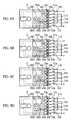
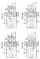
- Figs. 10A through 10Dillustrate a second embodiment of the present invention.
- desired attribute informationcan be output by selecting at least one of the location and the area size for forming the attribute information output sections 30A-30C.
- the attribute informationmay include calibration curve selection information (the sensor sensitivity) and measurement standard information.
- the biosensors 3A-3Care provided with at least one of these data.
- the attribute information output sections 30A-30C of the biosensors 3A-3Care formed between the end 25b of the working electrode 25 and the end 26b of the counterpart electrode 26.
- the attribute information output unit 30A shown in Fig. 10Ais brought into contact with second through fourth terminals 40b-40d of the concentration measuring device when the biosensor 3A is attached to the concentration measuring device.
- the attribute information output unit 30B shown in Fig. 10Bis formed so as to contact the third and fourth terminals 40c, 40d but not to contact the second terminal 40b in attaching the biosensor 3B.
- the attribute information output unit 30C shown in Fig. 10Cis formed so as to contact the second and third terminals 40band 40c but not to contact the fourth terminal 40d in attaching the biosensor 3C.
- the concentration measuring devicecan recognize attribute information of a biosensor 3D provided with no attribute information output section.
- attribute information output sections 30A'-30C'may be integrally formed with either of the working electrode 25 and the counterpart electrode 26.
- the detection of the attribute informationis performed by turning the first and fifth analog switches 41a, 41f off, turning the third analog switch 41c on, and turning one of the second and fourth analog switches 41b and 41d on while turning the other off.
- the second and third analog switches 41b, 41care turned on. Since the attribute information output section 30A is arranged between the second and third terminals 40b, 40c, these terminals are shorted. Then, the third and fourth analog switches 41c, 41d are turned on. As shown in Fig. 12B, the attribute information output section 30A is arranged between the third and fourth terminals 40c, 40d, and therefore the terminals 40c, 40d are shorted.
- a signalindicating that the second and third terminals 40b, 40c as well as the third and fourth terminals 40c, 40d are shorted in the biosensor 3A shown in Fig. 10A.
- Such a signalmaybe obtained by causing the detection unit 15 to detect whether or not a current is measured by the electric current measuring unit 13 (see Fig. 1).
- the biosensor 3B shown in Fig. 10Bthere is generated a signal indicating that the second and third terminals 40b, 40c are open while the third and fourth terminals 40c, 40d are shorted.
- the biosensor 3C shown in Fig. 10Cthere is generated a signal indicating that the second and third terminals 40b, 40c are shorted while the third and fourth terminals 40c, 40d are open.
- the biosensor 3D shown in Fig. 10Dthere is generated a signal indicating that the second and third terminals 40b, 40c as well as the third and fourth terminals 40c, 40d are open.
- the attribute information output section for outputting an open-short signalcan be formed by preparing a strip conductor or resistor set connection-breakable parts and then disconnecting or leaving the parts depending on kinds of information to be output.
- the attribute information output sections 30A-30Ccan output more kinds of information by setting a plurality of resistances.
- two (or more) kinds of short-related outputscan be separately used to indicate: shorted and having a greater resistance; or shorted and having a smaller resistance.
- the biosensors 3A-3Ccan output both the measurement standard information and the calibration curve selection information without causing any trouble. Further, when the biosensors 3A-3C are used together with a correction chip for calibration curve selection, the attribute information output sections 30A-30C can be arranged to output information that one of the biosensors 3A-3C is attached to the concentration measuring device.
- the resistancecan be adjusted by changing the cross-sectional area (thickness or width) of the attribute information output sections 30A-30C, the length of the sections 30A-30C, or the material for making the sections 30A-30C.
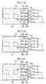
- Fig. 13illustrates a third embodiment of the present invention.
- the concentration measuring deviceincludes first-fourth terminals 42a-42d and a switching unit 43.
- the switching unit 43includes two analog switches 43a, 43b. In this arrangement, the analog switches 43a, 43b are operated to selectively provide a state where a voltage is applied across the first and fourth terminals 42a, 42d and a state where a voltage is applied across the second and third terminals 42b, 42c.
- a biosensor 3Eincludes an attribute information output section 30E formed between the ends 25b, 26b of the working and counterpart electrodes 25, 26.
- the attribute information output section 30Ehas a resistance corresponding to the attribute information to be output.
- the concentration measuring devicecan detect the attribute information of the biosensor 3E such as calibration curve selection information and measurement standard information.
- the first calibration curvemay correspond to a resistance of 2000-2600 ⁇ of the attribute information output section 30E
- the second calibration curvemay correspond to a resistance of 2600-3000 ⁇ of the attribute information output section 30E
- the third calibration curvemay correspond to a resistance of 3000-3800 ⁇ of the attribute information output section 30E.
- the attribute information to be outputmay include measurement standard information in addition to the calibration curve selection information.
- 2000-2200 ⁇ , 2600-2800 ⁇ and 3200-3400 ⁇may correspond to first measurement standard information
- 2200-2400 ⁇ , 2800-3000 ⁇ and 3400-3600 ⁇may correspond to second measurement standard information
- 2400-2600 ⁇ , 3000-3200 ⁇ and 3600-3800 ⁇may correspond to third measurement standard information.
- the resistances to be adoptedmay be taken from only one of a plurality of predetermined resistance ranges (2000-4000 ⁇ , 4000-6000 ⁇ , etc.).
- the concentration measuring devicemay be arranged to determine within which resistance range the resistance of the attribute information output section 30E falls. Based on this determination, the concentration measuring device can further determine whether or not the instrument provided with the section 30E is a biosensor (i.e., the instrument can output any information for enabling the concentration calculation).
- the number of the calibration curvesis not limited to three.
- the resistances described aboveare only for example's sake.
- the resistance rangeis not limited as long as the relationship between the calibration curve selection information and the calibration curve to be selected is well-defined and so is the relationship between the measurement standard and the measurement standard information.
- the resistance of the attribute information output section 30Ecan be adjusted by changing the amount of added conductive powder or the thickness and size of the attribute information output section 30E.
- the attribute information output section 30E of the biosensor 3Ecan be simultaneously formed with the working and counterpart electrodes 25, 26 under circumstances where biosensors 3E having the substantially same sensitivity can be stably supplied (i.e. where production lines are stably operated with the production conditions and the materials standardized).
- a mask for forming the working electrode 25 and counterpart electrode, 26is formed with an opening corresponding to the attribute information output section 30E. When this opening is rectangular, for example, the width or length of the opening may be varied for adjusting the resistance of the attribute information output section 30E.
- each production linecan utilize the mask having an opening suitable for the production line. Since there is no need to provide an additional production line for producing correction chips in addition to the sensor production line, the production cost can be relatively low.
- the resistance adjustment of the attribute information output section 30Emay be performed at a last stage after the overall characteristics of biosensor's sensitivities are grasped by sampling a number of biosensors 3E among concentration measuring sensors produced under the same conditions. This is an effective means under such circumstances that the sensitivity of the biosensors is unpredictable because of change inmaterials or in design of production lines, e. g. in an initial stage for launching the production lines.
- the resistance adjustmentmay be performed by providing a resistor element of a known resistance after the working electrode 25, the counterpart electrode 26 and a conductive part are formed. The adjustment may also be performed by modifying the surface state of the conductive part.
- the modificationmay be performed by forming an oxidized layer or a nitride layer by CVD, laminating a resistance material and a resistance material by PVD, implantingmetal ions into the conductive part, or laser trimming. These methods can provide the attribute information output portions having a variety of resistances by adjusting the surface modification time. This enables prompt action to cope with the change in materials or in design of production lines.
- a biosensor 3Fincludes an attribute information output section 30F consisting of first and second individual information parts 30Fa, 30Fb.
- the two individual information parts 30Fa, 30Fbcan be used to output open-short information between the second and the third terminals 40b, 40c as well as the third and the fourth terminals 40c, 40d. In this manner, it is possible to output more information than when the attribute information output section consists of only one output part.
- a biosensor 3Gincludes an attribute information output portion 30G arranged nearer to an end (attaching end) in relation to the ends 25b, 26b of the working and counterpart electrodes 25, 26.
- the attribute information output portion 30Gformed in a strip extending widthwise of the substrate 22.
- the output portion 30Goutputs attribute information distinguished depending on the resistance of the output portion 30G.
- the concentration measuring deviceincludes first and second terminals 44a, 44b. As shown in Fig. 15A, the first and second terminals 44a, 44b contact the attribute information output section 30G when the biosensor 3G is being attached to the concentration measuring device. As shown in Fig. 15B, when the attachment of the biosensor 3G to the concentration measuring device is completed, the terminals contact the ends 25b, 26b of the working and counterpart electrodes 25, 26. Therefore, the concentration measuring device does not need to have any terminal for causing the biosensor 3G to contact the attribute information output section 30G. This simplifies the structure of the concentration measuring device and provides a cost advantage.
- the attribute information output portions 30G', 30G"may be formed integrally with the working electrode 25 or the counterpart electrode 26.
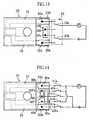
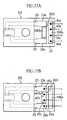
- Figs. 17A and 17Bshow a sixth embodiment of the present invention.
- a biosensor 3Hhas an attribute information output section 30H including first and second individual information output sections 30Ha, 30Hb.
- the first individual information output section 30Hais formed in the same portion as the attribute information output section 30G of the biosensor 3H shown in Fig. 15.
- the first individual information output section 30Hais formed in a strip extending over substantially the entire width of the substrate 22.
- the second individual information output section 30Hbis formed between the ends 25b, 26b of the working and counterpart electrodes 25, 26.
- the second individual information output section 30Hbis shorter than the first individual information output section 30Ha.
- the first and second individual information output sections 30Ha, 30Hbare fabricated in the same production step and made of the same material, and therefore differ in resistance.
- the concentration measuring deviceincludes first-fourth terminals 45a-45d for the first and second individual information output sections 30Ha, 30Hb of the attribute information output section 30H.
- the first and the fourth terminals 45a, 45dcontact the individual information output section 30Ha in attaching the biosensor 3H to the concentration measuring device.
- these terminalscontact the ends 2 5b, 2 6b of the working and counterpart electrodes 25, 26.
- the second and the third terminals 45b, 45ccontact the individual information output section 30Ha in attaching the biosensor 3H to the concentration measuring device.
- these terminalscontact the individual information output section 30Hb.
- the first output section 30Haoutputs individual information when the biosensor 3H is being attached to the concentration measuring device, while the second output section 30Hb outputs individual information when the attachment of the biosensor 3H to the concentration measuring device is completed.
- Figs. 18A-18Dshow a seventh embodiment of the present invention.
- a biosensor 3Ihas an attribute information output section 30I including first-third individual information output sections 30Ia-30Ic.
- the first-third individual information output sections 30Ia-30Icare formed in the same region as the attribute information output section 30G.
- the first-third individual information output sections 30Ia-30Icare formed in a strip extending widthwise of the substrate 22.
- the first-fourth terminals 45a-45dcontact the first-third individual information output sections 30Ia-30Ic in attaching the biosensor 3I to the concentration measuring device.
- This arrangementcan output various kinds of information with the use of the first-third individual information output sections 30Ia-30Ic.
- each first-third individual information output section 30Ia-30Icmay be 1 mm or less.
- the inventors of the present inventionproduced rectangular sample conductors by screen printing and then evaluated the production error based on the measurements of their resistance.
- the conductorswere 25 mm in length and 15 ⁇ m in thickness, but their widths came in three types: 3 mm (type. 1), 2 mm (type. 2) and 1 mm (type. 3). 20 conductors were prepared for each type.
- the conductorswere formed by placing a mask having an opening corresponding to the conductive part on a PET substrate, filling the opening with carbon ink, and then performing heat treatment.
- the carbon inkwas prepared to include carbon black powder (having a weight-average particle diameter of 5 ⁇ m or less) of 100 weight parts, polyvinyl butylenes of 25 weight parts as a binder resin, and butyl cellosolve acetate of 125 weight parts as a solvent.
- the heat treatmentwas performed for 30 minutes at 140 C°.
- the type. 1 of 3mm widthhas a standard deviation (SD) much larger than the types. 2 and 3, which is smaller in width than type. 1.
- the type. 1has a relative standard deviation (C. V.) much larger than the types. 2 and 3.
- the attribute information output sectionhas a width of 2mm or less.
- the biosensor 3I shown in Fig. 18the biosensor can be formed so that the individual information output sections have approximately desired resistances. In other words, it is possible to produce individual information output sections 30Ia-30Ic capable of outputting individual information which are easily distinguished from each other.
- the maximum value of type. 1does not overlap the minimum value of type. 2, while the maximum value of type. 2 does not overlap the minimum value of type. 3. Therefore, three kinds of attribute information output sections of 1mm, 2mm, and 3mm width can be distinguished from each other for selecting a calibration curve suitable for the sensitivity of the biosensor from the three kinds of calibration curves for example. Applying this to the biosensor 3G shown in Fig. 15, the attribute information output section 30G is formed to have one of the widths 1mm, 2mm and 3mm, thereby ensuring that the most appropriate calibration curve for the sensitivity of the biosensor 2 is selected from the three kinds of calibration curves, for example. In this manner, only adjusting the width of the attribute information output section 30G can provide a biosensor 3G capable of outputting information needed for selection of the calibration curve or detection of the measurement standard.
- Figs. 19-22show an eighth embodiment of the present invention.
- a concentration measurement device 1Bfirst selects a calibration curve suitable for a biosensor 3J when a correction chip 5 is attached, and then performs concentration calculation based on the selected calibration curve when the biosensor 3J is attached. Therefore, the correction chip 5 and the biosensor 3J are used as a set. On the market, one correction chip 5 may be sold together with one lot of biosensors 3J.
- the correction chip 5has a rectangle substrate 50 formed with a pair of electrodes 51, 52 and a measurement standard information output section 53.
- the paired electrodes 51, 52include front ends 51a, 52a bridged by a chip resistor 54.
- the chip resistor 54has a resistance corresponding to the sensitivity of the biosensor 3J. Therefore, the concentration measuring device 1B can select the most suitable calibration curve for the biosensor 3J based on a current flowing upon application of a constant voltage to the chip resistor 54 via the first and fifth terminals 40a, 40e.
- the electrodes 51, 52may be bridged directly or by a resistance material to output calibration curve information corresponding to the resistance measured with use of the electrodes 51, 52.
- the measurement standard information output section 53extends widthwise of the substrate 50 between the ends 51b, 51b of the electrodes 51, 52.
- the output section 53outputs information about a measurement standard applied to the biosensor 3J.
- the output section 53contacts the second through fourth terminals 40b-40d.
- the measurement standard information of the biosensor 3Jcan be obtained in accordance with a combination of open-short signals between the second and third terminals 41b, 41c and between the third and fourth terminals 41c, 41d by switching the analog switches 41b-41d.
- the measurement standard informationis recognized by the output section 53 having a structure shown in Figs. 10A through 10C, or without providing the output section 53, depending on desired measurement standard information.
- the biosensor 3Jhas a structure similar to those of the above-described biosensors 2, 3A-3I but with no attribute information output section (see Figs. 2, 10, 11-18) provided.
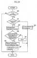
- the detection unit 15 of the concentrationmeasuring device 1Bdetects whether or not the correction chip 5 or the biosensor 3J (these elements are collectively referred to as "attachment” below) is mounted (S40). The determination may be performed by detecting whether or not a current flows when a voltage is applied across the first and fifth terminals 40a, 40e.
- the detection unit 15detects that the attachment 5, 3J is attached to the concentration measuring device 1B (S40: YES), the unit determines that the attachment is either of the correction chip 5 and the biosensor 3J (S41). This decision of the detection unit 15 may be made based on the current flowing at the second and third terminals 40b, 40c or at the third and fourth terminals 40c, 40d. If the detection unit 15 determines that the attachment is the biosensor 3J (S41 :NO), concentration measuring calculation is performed (S42). The calculation is performed by the same steps as described above with reference to Fig. 9.
- the detection unit 15determines that the attachment is the correction chip 5 (S41:YES)
- the measurement standard of the biosensor 3Jis recognized (S43).
- the recognition of the measurement standard applied to the biosensor 3Jcan be performed by obtaining a combination of open-short signals between the second and third terminals 41b, 41c and between the third and fourth terminals 41c, 41d.
- the concentration measuring device 1Bmay be designed to cope with a plurality of measurement standards and to select the most suitable standard for that of the biosensor 3J based on the measurement standard information from the correction chip.
- the detection unit 15obtains calibration curve selection information from the correction chip 5 (S46).
- the calibration curve selection informationis obtained as a current when a constant voltage is applied to the chip resistor 54.
- the currentcorrelates with the resistance of the chip resistor 54. Therefore, the correction chip 5 can be designed to output the desired calibration curve selection information depending on the resistance selected for the chip resistor 54, while the concentration measuring device 1B obtains the calibration curve selection information suitable for the sensitivity of the biosensor 3J.
- the concentration measuring device 1Bselects the most suitable calibration curve for the biosensor 3J from the calibration curves stored in the storage unit 14. Once the selection of the calibration curve is performed, the concentration calculation is performed based on the selected calibration curve until another calibration curve is selected by the attaching of a correction chip 5.
- the concentration measuring operationis terminated when the detection unit 15 determines that the attachment 3J, 5 is not mounted (S40:NO), when the concentration measurement (S42) is terminated, or when the error handling is terminated (S45).
- the devicecan select the measurement standard most suitable for the biosensor 3J set to the correction chip 5 to calculate the concentration based on the standard.
- the measurement standard information output section 53 of the correction chip 5may have the same structure as the attribute information output section of the described biosensor 2, 3A-3I (see Fig. 2, 10, 11-18).
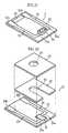
- Figs. 24 through 27show a ninth embodiment of the present invention.
- Fig. 24is a perspective view showing the concentration measuring device with a sensor cartridge.
- Figs. 25 and 26are sectional views taken along lines X1-X1 and X2-X2.
- Fig. 27is an enlarged view showing a principal portion of the sensor cartridge.
- a concentration measuring device 6is used with a sensor cartridge 7. As shown in Fig. 24, a concentration measuring device 6 is used with a sensor cartridge 7. As shown in Figs. 25 and 26, the sensor cartridge 7 accommodates aplurality of biosensors 8. The concentration measuring device 6 takes one of the biosensors 8 out of the sensor cartridge 7 to measure a concentration of a specific component in a sample liquid with the biosensor 8.
- the concentration measuring device 6has a housing 60 (see Fig. 24) internally provided with a push mechanism for pushing the biosensor 8 in the direction of an arrow A1 in Fig. 24, a transfer mechanism for transferring the biosensor 8, and an index mechanism for sequentially shifting the sensor cartridge 7 bit by bit.
- the transfer mechanism and the index mechanismmay be known means.
- the concentration measuring device 6includes a voltage applying unit, an electric current measuring unit, a storage unit, a calibration curve selection unit, a judging unit, a detection unit, a control unit, and a calculating unit.
- the housing 60is formedwith a cartridge mount 61 and an opening 62.
- the cartridge mount 61allows the movement of sensor cartridge 7, holds the sensor cartridge 7 and guides the sensor cartridge 7 being indexed.
- the opening 62communicates with the cartridge mount 61 so as to allow the biosensor 8 to project to the outside after is transferred by the transfer mechanism.
- the sensor cartridge 7includes a case 70, a sealing film 71, and an attribute information output section 72.
- the case 70includes a plurality of sensor holders 73.
- the sensor holder 73is open forward (in the direction of an arrow A1 shown in Figs. 24 and 25) and upward (in the direction of an arrow B1 shown in Figs. 24 and 25).
- the sensor holders 73are disposedat apitch P in the longitudinal direction (in directions of arrows C1, C2), where the pitch P corresponds to the indexing pitch of the index mechanism for the sensor cartridge 7.
- Each sensor holder 73accommodates one sensor 8.
- the biosensor 8has a structure where the attribute information output section and the correction information output section are omitted from the biosensor shown in Fig. 2.
- the biosensor 8is accommodated in the sensor holder 73 in a manner such that the sample liquid inlet 80 faces in the transferring direction A1 of the biosensor, and that the sensor is held in direct contact with a side surface 73a and an upright step portion 73A. In this state, the biosensor 8 is spaced from side surfaces 73b and 73B with gaps 73c, 73C.
- the sealing film 71is applied to cover the sensor holders 73 collectively.
- the sealing film 71may be made of metal thin film or plastic film, or formed by combining these films.
- Fig. 25shows a draw-out mechanism including first and second cutters 90, 91 depicted in imaginary lines.
- the draw-out mechanismincludes first and second cutters 90, 91.
- the first cutter 90is movable upward and downward or in the directions B1, B2. Moving downward, the first cutter 90 makes a cut in the sealing film 71 at the front portion relative to the biosensor 8. At this time, the first cutter 90 plunges into the gap 73c as shown in Fig. 26.
- the second cutter 91 shown in Fig. 25is movable upward and downward or in the directions B1, B2, and forward and backward or in the direction A1, A2. Moving downward, the second cutter 91 makes a cut in the rear portion of the sealing film 71. At this time, the second cutter 91 plunges into the gap 73c.
- the first cutter 90is moved upward B1 and the second cutter 91 is moved forwardA1, thereby moving the biosensor 8 out of the sensor cartridge 7.
- the biosensor 8is further moved forward A1 by the transfer mechanism.
- the biosensor 8 with the sample liquid inlet 80is partly projected from the opening 62 of the housing 60.
- the attribute information output section 72formed on a sheet 74, has a plurality of individual information output sections 72a, 72b, 72c.
- the sheet 74is adhered on to the sealing film 71.
- the individual information output sections 72a- 72care strips formed by e.g. screen printing and extending widthwise of the sensor cartridge 7.
- the attribute information output section 72may consist of one conductor.
- the concentration measuring device 6has a calibration curve selection unit (not shown) selecting the calibration curve based on calibration curve determination information detected via first-third terminals 93-95.
- the terminals 93-95are located so as to contact the individual information output sections 72a-72c in inserting the sensor cartridge 7.
- the terminals 93-95are leaf springs to press the sensor cartridge 7 downward.
- the terminals 93-95is provided with pivots 93a, 94b, 95c, respectively.
- the pivots 93a-95cprovide point-contacts between the terminals 93-95 and the individual information output sections 72a-72c, respectively.
- the calibration curve selection unitdetermines the calibration curve suitable for the sensitivity of the biosensor 8 based on the calibration curve selection information.
- the judging unitjudges whether or not the measurement standard of the biosensor 8 matches that of the concentration measuring device 6 (see Fig. 1).
- the biosensor 8 proj ecting from the housing 60is introduced with a sample liquid via the sample liquid inlet 80.
- the concentration measuring device 6calculates the concentration of the specific components in the sample liquid (see Fig. 1).
- the calibration curve determinationcan be performed without attaching the correction chip or button operation.
- the userhas no role in the determination of the calibration curve, which results in preventing failure of the calibration curve determination due to user's carelessness.
Landscapes
- Health & Medical Sciences (AREA)
- Engineering & Computer Science (AREA)
- Life Sciences & Earth Sciences (AREA)
- Biomedical Technology (AREA)
- Physics & Mathematics (AREA)
- Chemical & Material Sciences (AREA)
- Biochemistry (AREA)
- General Health & Medical Sciences (AREA)
- Molecular Biology (AREA)
- Urology & Nephrology (AREA)
- Optics & Photonics (AREA)
- Food Science & Technology (AREA)
- Medicinal Chemistry (AREA)
- Analytical Chemistry (AREA)
- Hematology (AREA)
- General Physics & Mathematics (AREA)
- Biophysics (AREA)
- Immunology (AREA)
- Pathology (AREA)
- Investigating Or Analyzing Materials By The Use Of Electric Means (AREA)
- Investigating Or Analysing Biological Materials (AREA)
- Analysing Materials By The Use Of Radiation (AREA)
- Measurement Of Radiation (AREA)
Abstract
Description
| Sample NO. | Carbon Resistance (Ω) | ||
| Width 3mm (Type 1) | Width 2mm (Type 2) | Width 1mm (Type 3) | |
| 1 | 530 | 725 | 920 |
| 2 | 660 | 825 | 990 |
| 3 | 662 | 876 | 1090 |
| 4 | 685 | 904 | 1123 |
| 5 | 581 | 758 | 935 |
| 6 | 618 | 780 | 942 |
| 7 | 665 | 862 | 1059 |
| 8 | 589 | 816 | 1043 |
| 9 | 544 | 791 | 1038 |
| 10 | 577 | 773 | 969 |
| 11 | 617 | 902 | 1187 |
| 12 | 373 | 732 | 1091 |
| 13 | 517 | 731 | 945 |
| 14 | 414 | 695 | 976 |
| 15 | 776 | 908 | 1040 |
| 16 | 556 | 795 | 1034 |
| 17 | 720 | 898 | 1076 |
| 18 | 602 | 835 | 1068 |
| 19 | 518 | 761 | 1004 |
| 20 | 596 | 805 | 1014 |
| Avg. | 590 | 808.6 | 1027.2 |
| SD | 95.6 | 66.2 | 69.0 |
| C.V.(%) | 16.2 | 8.2 | 6.7 |
Claims (26)
- A measurement instrument which is attached to a concentrationmeasuring device for calculating a concentration based onconcentration calculation information and is capable ofoutputting the concentration calculation information to theconcentration measuring device, the measurement instrumentcomprising,
an attribute information output section for outputtingattribute information relating to an attribute of themeasurement instrument as an electric physical quantity,
wherein the attribute information is provided based onat least one of conditions including a resistance of the attributeinformation output section, a location of the attributeinformation output section, and a size of a region on whichthe attribute information output section is formed. - The measurement instrument according to claim 1, whereinthe attribute information is utilized for enabling theconcentration measuring device to select a calibration curvesuitable for the measurement instrument.
- The measurement instrument according to claim 2, whereinthe attribute information is utilized for enabling theconcentration measuring device to select a calibration curvesuitable for sensitivity of the measurement instrument.
- The measurement instrument according to claim 1, whereinthe attribute information relates to a measurement standardapplied to the measurement instrument.
- The measurement instrument according to claim 1, whereinthe attribute information output section comprises a pluralityof individual information output sections for outputtingindividual information as electric physical quantity.
- The measurement instrument according to claim 1, furthercomprising a substrate at least having an end portion insertedinto the concentration measuring device for concentrationmeasurement,
wherein the attribute information output section comprisesa strip formed in the end portion and having a width of no greaterthan 2 mm. - The measurement instrument according to claim 1, furthercomprising: a substrate having an end portion inserted intothe concentration measuring device for concentrationmeasurement; and a calculation information output sectionformed on the end portion for outputting the concentrationcalculation information;
wherein the attribute information output section isprovided on the end portion and between the calculationinformation output section and a leading edge of the substratethat is inserted into the concentration measuring device. - The measurement instrument according to claim 1, whereinthe attribute information output section comprises: first andsecond portions brought into contact with terminals of theconcentration measuring device; and one or a plurality ofconnection-breakable parts connecting the first and secondportions, and
wherein the attribute information is provided in theattribute information output section by selectively breakingor leaving intact the one or the plurality ofconnection-breakable parts. - The measurement instrument according to claim 1, whereinthe attribute information correlates with a resistance of theattribute information output section,
the measurement instrument further comprising a correctioninformation output section for outputting correctioninformation correlating with a discrepancy between an actualresistance of the attribute information output section and aresistance preset for the attribute information output section. - The measurement instrument according to claim 1, whereinthe attribute information output section is arranged to outputidentification information for informing the concentrationmeasuring device that the measurement instrument is arrangedto output the concentration calculation information.
- A method of making a measurement instrument, the methodcomprising the step of making an attribute information outputsection arranged to output attribute information relating toan attribute of the measurement instrument,
wherein the step comprises: a first operation for formingfirst and second elements that are brought into contact withterminals of a concentration measuring device when themeasurement instrument is attached to the concentrationmeasuring device, the first operation also for forming one orplurality of connection-breakable parts connecting the firstand second elements; and a second operation for disconnectinga connection-breakable part selected from the one or theplurality of connection-breakable parts in accordance withinformation outputted from the attribute information outputsection. - A measurement instrument attached to a concentrationmeasuring device that performs concentration calculation basedon concentration calculation information, the instrument beingarranged to output the concentration calculation informationto the concentration measuring device,
wherein the measurement instrument comprises a measurementstandard information output section arranged to outputmeasurement standard information regarding a measurementstandard applied to the measurement instrument. - A set comprising a measurement instrument and a measurementauxiliary instrument,
wherein the measurement instrument is attached to aconcentration measuring device that performs concentrationcalculation based on concentration calculation information,the measurement instrument being arranged to output theconcentration calculation information to the concentrationmeasuring device,
wherein the measurement auxiliary instrument is attachedto the concentration measuring device and includes a measurementstandard information output section arranged to outputmeasurement standard information relating to a measurementstandard applied to the measurement instrument. - The set of the measurement instrument and the measurementauxiliary instrument according to claim 13, wherein themeasurement standard information is provided based on at leastone of conditions including a resistance of the measurementstandard information output section, a location of themeasurement standard information output section, and a sizeof a region on which the measurement standard information outputsection is formed.
- A concentration measuring device used with a measurementinstrument attached thereto, the measurement instrumentcomprising an attribute information output section foroutputting attribute information relating to an attribute of the measurement instrument, the attribute information beingprovided based on at least one of conditions including aresistance of the attribute information output section, alocation of the attribute information output section, and asize of a region on which the attribute information output sectionis formed, the concentration measuring device comprising:wherein a concentration calculation-related operation isperformed based on the attribution information detected by therecognizer.a recognizer for detecting the attribute information, and
- The concentration measuring device according to claim 15,wherein the attribute information output section is arrangedto output calibration curve selection information, as theattribution information, for selecting a calibration curvesuitable for the measurement instrument, the concentrationmeasuring device further comprising:a storage unit storing information regarding a pluralityof calibration curves; anda calibration curve selection unit selecting a specificcalibration curve suitable for the measurement instrument fromthe plurality of calibration curves.
- The concentration measuring device according to claim 15,wherein the attribute information output section is arrangedto output measurement standard information, as the attributioninformation, regarding a measurement standard applied to the measurement instrument,
the concentration measuring device further comprising ajudging unit determining whether it is possible or not to performconcentration measurement with the measurement instrument basedon the attribute information. - The concentration measuring device according to claim 15,wherein the recognizer comprises a plurality of terminalsbrought into contact with the attribute information outputsection, the recognizer being arranged to detect the attributeinformation when constant voltage or constant current is appliedto the attribute information output section via the terminals.
- A sensor cartridge comprising a plurality of measurementinstruments arranged to output concentration measurementinformation correlating with a concentration of a specificcomponent in a sample liquid, the sensor cartridge being attachedto a concentration measuring device which calculates aconcentration of the specific component based on theconcentration calculation information supplied from themeasurement instrument,
the sensor cartridge also comprising an attributeinformation output section arranged to output an attributeinformation relating to an attribute of the plurality ofmeasurement instrument. - The sensor cartridge according to claim 19, wherein theattribute information is provided based on at least one ofconditions including a resistance of the attributioninformation output section, a location of the attributeinformation output section, and a size of a region on whichthe attribute information output section is formed.
- The sensor cartridge according to claim 19, wherein theattribute information is utilized for enabling theconcentration measuring device to select a calibration curvesuitable for the measurement instruments.
- The sensor cartridge according to claim 19, wherein theattribute information relates to a measurement standard appliedto the measurement instruments.
- Aconcentrationmeasuring deviceusedwith a sensor cartridgethat accommodates a plurality of measurement instruments, themeasuring device performing concentration calculation basedon concentration measurement information outputted from ameasurement instrument taken from the sensor cartridge, thesensor cartridge comprising an attribute information outputsection for outputting attribute information relating to anattribute of the measurement instruments,
the measuring device comprising a recognizer for detectingthe attribute information,
wherein a concentration calculation-related specific operation is performed based on the attribute informationdetected by the recognizer. - The concentration measuring device according to claim 23,wherein the attribute information of the measurement instrumentis based on at least one of conditions including a resistanceof the attribute information output section, a location of theattribute information output section, and a size of a regionon which the attribute information output section is formed.
- The concentration measuring device according to claim 23,wherein the attribute information is used to select a calibrationcurve suitable for the measurement instruments,
the measuring device further comprising:a storage unit storing information relating to a pluralityof calibration curves; anda calibration curve selection unit selecting a specificcalibration curve suitable for the measurement instrument fromthe plurality of calibration curves. - The concentration measuring device according to claim 23,further comprising: a cartridge mount for mounting the sensorcartridge; and a plurality of terminals brought into contactwith the attribute information output section;
wherein the terminals come into contact with the attributeinformation output section when the sensor cartridge is beingmounted or after the sensor cartridge has been mounted.
Priority Applications (1)
| Application Number | Priority Date | Filing Date | Title |
|---|---|---|---|
| EP09012668AEP2144060A1 (en) | 2001-09-28 | 2002-09-27 | Measurement instrument and concentration measuring device |
Applications Claiming Priority (5)
| Application Number | Priority Date | Filing Date | Title |
|---|---|---|---|
| JP2001301009 | 2001-09-28 | ||
| JP2001301009 | 2001-09-28 | ||
| JP2002078183 | 2002-03-20 | ||
| JP2002078183 | 2002-03-20 | ||
| PCT/JP2002/010137WO2003029804A1 (en) | 2001-09-28 | 2002-09-27 | Measurement instrument and concentration measurement apparatus |
Related Child Applications (2)
| Application Number | Title | Priority Date | Filing Date |
|---|---|---|---|
| EP09012668ADivisionEP2144060A1 (en) | 2001-09-28 | 2002-09-27 | Measurement instrument and concentration measuring device |
| EP09012668.1Division-Into | 2009-10-07 |
Publications (3)
| Publication Number | Publication Date |
|---|---|
| EP1431758A1true EP1431758A1 (en) | 2004-06-23 |
| EP1431758A4 EP1431758A4 (en) | 2009-01-21 |
| EP1431758B1 EP1431758B1 (en) | 2013-11-13 |
Family
ID=26623288
Family Applications (2)
| Application Number | Title | Priority Date | Filing Date |
|---|---|---|---|
| EP09012668AWithdrawnEP2144060A1 (en) | 2001-09-28 | 2002-09-27 | Measurement instrument and concentration measuring device |
| EP02772957.3ARevokedEP1431758B1 (en) | 2001-09-28 | 2002-09-27 | Measurement instrument and concentration measurement apparatus |
Family Applications Before (1)
| Application Number | Title | Priority Date | Filing Date |
|---|---|---|---|
| EP09012668AWithdrawnEP2144060A1 (en) | 2001-09-28 | 2002-09-27 | Measurement instrument and concentration measuring device |
Country Status (5)
| Country | Link |
|---|---|
| US (1) | US7491303B2 (en) |
| EP (2) | EP2144060A1 (en) |
| JP (2) | JP4264478B2 (en) |
| CN (1) | CN100476421C (en) |
| WO (1) | WO2003029804A1 (en) |
Cited By (39)
| Publication number | Priority date | Publication date | Assignee | Title |
|---|---|---|---|---|
| WO2004113915A1 (en)* | 2003-06-20 | 2004-12-29 | Roche Diagnostics Gmbh | System and method for coding information on a biosensor test strip |
| WO2005012900A1 (en)* | 2003-06-20 | 2005-02-10 | Roche Diagnostics Gmbh | Biosensor with multiple electrical functionalities |
| WO2006127635A1 (en)* | 2005-05-24 | 2006-11-30 | Bayer Healthcare Llc | Sensor package with an interim auto-calibration circuit |
| US7244264B2 (en) | 2002-12-03 | 2007-07-17 | Roche Diagnostics Operations, Inc. | Dual blade lancing test strip |
| US7452457B2 (en) | 2003-06-20 | 2008-11-18 | Roche Diagnostics Operations, Inc. | System and method for analyte measurement using dose sufficiency electrodes |
| WO2009061648A1 (en)* | 2007-11-06 | 2009-05-14 | Bayer Healthcare Llc | Auto-calibrating test sensors |
| WO2009076263A1 (en) | 2007-12-10 | 2009-06-18 | Bayer Healthcare Llc | An auto-calibrating test sensor and method of making the same |
| US7556723B2 (en) | 2004-06-18 | 2009-07-07 | Roche Diagnostics Operations, Inc. | Electrode design for biosensor |
| US7569126B2 (en) | 2004-06-18 | 2009-08-04 | Roche Diagnostics Operations, Inc. | System and method for quality assurance of a biosensor test strip |
| US7597793B2 (en) | 2003-06-20 | 2009-10-06 | Roche Operations Ltd. | System and method for analyte measurement employing maximum dosing time delay |
| US7601299B2 (en) | 2004-06-18 | 2009-10-13 | Roche Diagnostics Operations, Inc. | System and method for coding information on a biosensor test strip |
| US7604721B2 (en) | 2003-06-20 | 2009-10-20 | Roche Diagnostics Operations, Inc. | System and method for coding information on a biosensor test strip |
| US7645421B2 (en) | 2003-06-20 | 2010-01-12 | Roche Diagnostics Operations, Inc. | System and method for coding information on a biosensor test strip |
| US7645373B2 (en) | 2003-06-20 | 2010-01-12 | Roche Diagnostic Operations, Inc. | System and method for coding information on a biosensor test strip |
| US7718439B2 (en) | 2003-06-20 | 2010-05-18 | Roche Diagnostics Operations, Inc. | System and method for coding information on a biosensor test strip |
| US7780827B1 (en) | 2001-08-29 | 2010-08-24 | Roche Diagnostics Operations, Inc. | Biosensor |
| US7875240B2 (en) | 2005-04-19 | 2011-01-25 | Bayer Healthcare Llc | Auto-calibration label and method of forming the same |
| WO2011027130A1 (en)* | 2009-09-04 | 2011-03-10 | Lifescan Scotland Limited | Methods, system and device to identify a type of test strip |
| US7919045B2 (en) | 2005-04-19 | 2011-04-05 | Bayer Healthcare Llc | Auto-calibration label and methods of forming the same |
| US7981678B2 (en) | 2007-08-06 | 2011-07-19 | Bayer Healthcare Llc | System and method for automatic calibration |
| WO2011106214A1 (en)* | 2010-02-24 | 2011-09-01 | Conductive Technologies, Inc. | Laminated electrochemical sensor with controlled variation of working electrode |
| EP2363706A2 (en)* | 2006-11-09 | 2011-09-07 | Nipro Diagnostics, Inc. | Diagnostic strip coding system |
| US8058077B2 (en) | 2003-06-20 | 2011-11-15 | Roche Diagnostics Operations, Inc. | Method for coding information on a biosensor test strip |
| US8124014B2 (en) | 2008-06-09 | 2012-02-28 | Bayer Healthcare Llc | Auto-calibration circuit or label and method of forming the same |
| US8206565B2 (en) | 2003-06-20 | 2012-06-26 | Roche Diagnostics Operation, Inc. | System and method for coding information on a biosensor test strip |
| US8298828B2 (en) | 2003-06-20 | 2012-10-30 | Roche Diagnostics Operations, Inc. | System and method for determining the concentration of an analyte in a sample fluid |
| EP1736763A4 (en)* | 2004-04-12 | 2012-12-05 | Arkray Inc | ANALYSIS DEVICE |
| WO2013017218A1 (en)* | 2011-07-29 | 2013-02-07 | Roche Diagnostics Gmbh | Encoded biosensors and methods of manufacture and use thereof |
| US8424763B2 (en) | 2008-10-07 | 2013-04-23 | Bayer Healthcare Llc | Method of forming an auto-calibration circuit or label |
| US8551308B2 (en) | 1999-10-04 | 2013-10-08 | Roche Diagnostics Operations, Inc. | Biosensor and method of making |
| EP2051072A3 (en)* | 2007-10-19 | 2013-10-23 | HMD BioMedical Inc. | Test strip identification function and test instrument using the same |
| EP2193366A4 (en)* | 2007-09-04 | 2014-01-15 | Ceragem Medisys Inc | Biosensor and readout meter |
| WO2014096826A1 (en)* | 2012-12-20 | 2014-06-26 | Lifescan Scotland Limited | Electrical connector for substrate having conductive tracks |
| US9012232B2 (en) | 2005-07-15 | 2015-04-21 | Nipro Diagnostics, Inc. | Diagnostic strip coding system and related methods of use |
| EP2833132A4 (en)* | 2012-03-31 | 2016-02-17 | Leadway Hk Ltd | AUTOMATIC ENCODING DEVICE, BIOSENSOR EQUIPPED WITH SAME, AND METHOD FOR MANUFACTURING THE SAME |
| WO2017039976A1 (en) | 2015-08-11 | 2017-03-09 | Roche Diabetes Care, Inc. | Encoded biosensors and methods of manufacture and use thereof |
| US9754708B2 (en) | 2011-07-29 | 2017-09-05 | Roche Diabetes Care, Inc. | Encoded biosensors and methods of manufacture and use thereof |
| US9927387B2 (en) | 2005-07-15 | 2018-03-27 | Trividia Health, Inc. | Embedded strip lot autocalibration |
| EP1922541B1 (en)* | 2005-09-10 | 2019-06-26 | F. Hoffmann-La Roche AG | Method for determining a scaling factor for an output of an electrochemical cell |
Families Citing this family (54)
| Publication number | Priority date | Publication date | Assignee | Title |
|---|---|---|---|---|
| JPS5993161A (en)* | 1982-11-16 | 1984-05-29 | 松下冷機株式会社 | Refrigerator |
| US20060091006A1 (en)* | 1999-11-04 | 2006-05-04 | Yi Wang | Analyte sensor with insertion monitor, and methods |
| US6616819B1 (en) | 1999-11-04 | 2003-09-09 | Therasense, Inc. | Small volume in vitro analyte sensor and methods |
| JP4447009B2 (en) | 2003-06-20 | 2010-04-07 | エフ ホフマン−ラ ロッシュ アクチェン ゲゼルシャフト | Test strip with slot vent opening |
| US7920906B2 (en) | 2005-03-10 | 2011-04-05 | Dexcom, Inc. | System and methods for processing analyte sensor data for sensor calibration |
| US9247900B2 (en) | 2004-07-13 | 2016-02-02 | Dexcom, Inc. | Analyte sensor |
| US8394337B2 (en)* | 2003-12-31 | 2013-03-12 | Nipro Diagnostics, Inc. | Test strip container with integrated meter |
| US8394328B2 (en)* | 2003-12-31 | 2013-03-12 | Nipro Diagnostics, Inc. | Test strip container with integrated meter having strip coding capability |
| JP2006015068A (en)* | 2004-07-05 | 2006-01-19 | Nishitomo Co Ltd | Biological information measuring sensor and biological information measuring apparatus |
| US7654956B2 (en) | 2004-07-13 | 2010-02-02 | Dexcom, Inc. | Transcutaneous analyte sensor |
| US7418285B2 (en)* | 2004-12-29 | 2008-08-26 | Abbott Laboratories | Analyte test sensor and method of manufacturing the same |
| CN101031802B (en)* | 2005-01-07 | 2012-11-07 | 积水化学工业株式会社 | Detection device using cartridge |
| US7545272B2 (en) | 2005-02-08 | 2009-06-09 | Therasense, Inc. | RF tag on test strips, test strip vials and boxes |
| JP4631027B2 (en)* | 2005-03-29 | 2011-02-16 | 独立行政法人産業技術総合研究所 | IC tag mounted biosensor and its package |
| JP2009507224A (en) | 2005-08-31 | 2009-02-19 | ユニヴァーシティー オブ ヴァージニア パテント ファンデーション | Improving the accuracy of continuous glucose sensors |
| US8012321B2 (en)* | 2006-02-27 | 2011-09-06 | Sumitomo Electric Industries, Ltd. | Biosensor chip, biosensor system and measuring instrument thereof |
| US8224415B2 (en) | 2009-01-29 | 2012-07-17 | Abbott Diabetes Care Inc. | Method and device for providing offset model based calibration for analyte sensor |
| US7653425B2 (en) | 2006-08-09 | 2010-01-26 | Abbott Diabetes Care Inc. | Method and system for providing calibration of an analyte sensor in an analyte monitoring system |
| US9675290B2 (en) | 2012-10-30 | 2017-06-13 | Abbott Diabetes Care Inc. | Sensitivity calibration of in vivo sensors used to measure analyte concentration |
| US8219173B2 (en) | 2008-09-30 | 2012-07-10 | Abbott Diabetes Care Inc. | Optimizing analyte sensor calibration |
| US8478557B2 (en) | 2009-07-31 | 2013-07-02 | Abbott Diabetes Care Inc. | Method and apparatus for providing analyte monitoring system calibration accuracy |
| US20080274552A1 (en)* | 2007-05-04 | 2008-11-06 | Brian Guthrie | Dynamic Information Transfer |
| US8239166B2 (en) | 2007-05-14 | 2012-08-07 | Abbott Diabetes Care Inc. | Method and apparatus for providing data processing and control in a medical communication system |
| JP2009008574A (en)* | 2007-06-29 | 2009-01-15 | Sumitomo Electric Ind Ltd | Sensor chip, biosensor cartridge, and biosensor device |
| US8206564B2 (en)* | 2007-07-23 | 2012-06-26 | Bayer Healthcare Llc | Biosensor calibration system |
| US7943022B2 (en)* | 2007-09-04 | 2011-05-17 | Lifescan, Inc. | Analyte test strip with improved reagent deposition |
| KR20150108949A (en)* | 2007-10-10 | 2015-09-30 | 아가매트릭스, 인코포레이티드 | Identification method for electro chemical test strips |
| CN101430327B (en)* | 2007-11-08 | 2014-06-11 | 厚美德生物科技股份有限公司 | Detection test piece with identification function and detection device thereof |
| US7809512B2 (en)* | 2007-11-11 | 2010-10-05 | Bayer Healthcare Llc | Biosensor coding system |
| US8032321B2 (en)* | 2008-07-15 | 2011-10-04 | Bayer Healthcare Llc | Multi-layered biosensor encoding systems |
| WO2010043067A1 (en)* | 2008-10-13 | 2010-04-22 | 红电医学科技股份有限公司 | Test piece reading device and test piece used therein |
| DK3689237T3 (en) | 2009-07-23 | 2021-08-16 | Abbott Diabetes Care Inc | Method of preparation and system for continuous analyte measurement |
| US9314195B2 (en) | 2009-08-31 | 2016-04-19 | Abbott Diabetes Care Inc. | Analyte signal processing device and methods |
| DE102010030874A1 (en)* | 2010-07-02 | 2012-01-05 | Endress + Hauser Conducta Gesellschaft für Mess- und Regeltechnik mbH + Co. KG | Potentiometric probe for measuring a measured quantity of a measuring medium contained in a container |
| CN103167909A (en)* | 2010-10-20 | 2013-06-19 | 皇家飞利浦电子股份有限公司 | Devices with RFID tags and fluidic elements |
| CN102183570A (en)* | 2011-02-14 | 2011-09-14 | 北京软测科技有限公司 | Implementation method and detector for improving blood detection accuracy |
| JP5703072B2 (en)* | 2011-03-08 | 2015-04-15 | 富士フイルム株式会社 | Biochemical analysis cartridge and biochemical analysis device |
| CN103364458A (en)* | 2012-04-01 | 2013-10-23 | 郡是株式会社 | Measurement and display device |
| JP5978868B2 (en)* | 2012-09-06 | 2016-08-24 | オムロンヘルスケア株式会社 | Test piece for measuring biological components, measuring device main body, and biological component measuring device including them |
| WO2014052136A1 (en) | 2012-09-26 | 2014-04-03 | Abbott Diabetes Care Inc. | Method and apparatus for improving lag correction during in vivo measurement of analyte concentration with analyte concentration variability and range data |
| JP6048109B2 (en)* | 2012-12-14 | 2016-12-21 | オムロンヘルスケア株式会社 | Test piece for measuring biological components and method for producing the same |
| JP6315200B2 (en)* | 2014-10-17 | 2018-04-25 | 株式会社タニタ | Sensor cartridge and measuring device |
| US20160178559A1 (en)* | 2014-12-17 | 2016-06-23 | Lifescan Scotland Limited | Universal strip port connector |
| JP6834317B2 (en)* | 2016-10-03 | 2021-02-24 | 大日本印刷株式会社 | Microbial contaminant detection device and microbial contaminant detection method |
| EP3618712A1 (en) | 2017-05-03 | 2020-03-11 | Abbott Diabetes Care Inc. | Systems, devices, and methods with duration-based adjustment of sensor data |
| CN107290393B (en)* | 2017-07-31 | 2019-07-09 | 南京鱼跃软件技术有限公司 | A kind of identification method of automatic coding |
| EP4218568A1 (en) | 2017-08-18 | 2023-08-02 | Abbott Diabetes Care Inc. | Analyte monitoring system storing a measured electrical characteristic of the in vivo analyte sensor of the system as individualized calibration information |
| EP4293361A3 (en)* | 2017-12-26 | 2024-07-03 | Hitachi High-Tech Corporation | Automated analyzer and automated analysis method |
| JP7071635B2 (en)* | 2018-07-19 | 2022-05-19 | 東亜ディーケーケー株式会社 | Measuring device and main body of measuring device |
| CN109482426A (en)* | 2018-10-15 | 2019-03-19 | 苏州席正通信科技有限公司 | A kind of control method of binder use process |
| JP2021039137A (en)* | 2020-12-09 | 2021-03-11 | 大日本印刷株式会社 | Microorganism contaminant detection device and microorganism contaminant detection method |
| EP4033243B1 (en)* | 2021-01-22 | 2025-10-15 | Infineon Technologies AG | Gas sensing device and method for determining a calibrated measurement value for a concentration of a target gas |
| JP2023116144A (en) | 2022-02-09 | 2023-08-22 | アークレイ株式会社 | Testing tool and measurement apparatus |
| US20230333050A1 (en)* | 2022-04-19 | 2023-10-19 | Lg Electronics Inc. | Biosensor chip and biosensor cartridges having the same |
Family Cites Families (26)
| Publication number | Priority date | Publication date | Assignee | Title |
|---|---|---|---|---|
| US4963245A (en)* | 1986-05-02 | 1990-10-16 | Ciba Corning Diagnostics Corp. | Unitary multiple electrode sensor |
| JPH01225300A (en)* | 1988-03-04 | 1989-09-08 | Fujitsu Ltd | ultrasonic probe |
| GB8817421D0 (en)* | 1988-07-21 | 1988-08-24 | Medisense Inc | Bioelectrochemical electrodes |
| JPH0820412B2 (en)* | 1990-07-20 | 1996-03-04 | 松下電器産業株式会社 | Quantitative analysis method and device using disposable sensor |
| JPH0810208B2 (en) | 1990-07-20 | 1996-01-31 | 松下電器産業株式会社 | Biosensor and biosensor measuring device |
| DE4041905A1 (en)* | 1990-12-27 | 1992-07-02 | Boehringer Mannheim Gmbh | TEST CARRIER ANALYSIS SYSTEM |
| JP2976635B2 (en)* | 1991-10-01 | 1999-11-10 | 東陶機器株式会社 | Chemical component analysis sensor |
| DE4139121C1 (en)* | 1991-11-28 | 1993-06-03 | Petermann, Geb. Hirsch, Heike, 8520 Erlangen, De | |
| JP2754109B2 (en)* | 1992-01-16 | 1998-05-20 | 富士写真フイルム株式会社 | Film cartridge for chemical analysis |
| JP2541081B2 (en)* | 1992-08-28 | 1996-10-09 | 日本電気株式会社 | Biosensor and method of manufacturing and using biosensor |
| JPH0810208A (en) | 1994-06-30 | 1996-01-16 | Toshiba Corp | Dishwasher |
| JPH0820412A (en) | 1994-07-05 | 1996-01-23 | Daifuku Co Ltd | Controller of rotary rack |
| JPH0843405A (en)* | 1994-07-28 | 1996-02-16 | Fuji Photo Film Co Ltd | Instrument for biochemical analysis |
| JPH0894629A (en) | 1994-09-21 | 1996-04-12 | Fuji Photo Film Co Ltd | Sampling device for dry analysis element |
| JPH08114603A (en)* | 1994-10-17 | 1996-05-07 | Fuji Photo Film Co Ltd | Cartridge for dry-type analysis film and film take-out device |
| US5856195A (en)* | 1996-10-30 | 1999-01-05 | Bayer Corporation | Method and apparatus for calibrating a sensor element |
| JP3702582B2 (en) | 1997-06-03 | 2005-10-05 | Nok株式会社 | Measuring method using biosensor |
| ES2323393T3 (en)* | 1997-07-22 | 2009-07-14 | Arkray, Inc | DENSITOMETER |
| JP2000019147A (en) | 1998-07-01 | 2000-01-21 | Nok Corp | Reaction product measuring device |
| EP1118856A4 (en)* | 1998-09-29 | 2008-07-23 | Omron Healthcare Co Ltd | Sample component analysis system and sensor chip and sensor pack used for the system |
| JP2000171427A (en) | 1998-09-29 | 2000-06-23 | Omron Corp | Sample component analyzing system and sensor chip and sensor pack used therefor |
| US6616819B1 (en)* | 1999-11-04 | 2003-09-09 | Therasense, Inc. | Small volume in vitro analyte sensor and methods |
| JP4184573B2 (en)* | 2000-04-28 | 2008-11-19 | 松下電器産業株式会社 | Biosensor |
| EP2151683A3 (en)* | 1999-11-15 | 2010-07-28 | Panasonic Corporation | Biosensor, thin film electrode forming method, quantification apparatus, and quantification method |
| JP4621860B2 (en)* | 2000-02-23 | 2011-01-26 | アークレイ株式会社 | Sensor cartridge, sensor supply device, and measurement device |
| WO2001071328A1 (en)* | 2000-03-22 | 2001-09-27 | All Medicus Co., Ltd. | Electrochemical biosensor test strip with recognition electrode and readout meter using this test strip |
- 2002
- 2002-09-27WOPCT/JP2002/010137patent/WO2003029804A1/enactiveApplication Filing
- 2002-09-27JPJP2003532966Apatent/JP4264478B2/ennot_activeExpired - Lifetime
- 2002-09-27EPEP09012668Apatent/EP2144060A1/ennot_activeWithdrawn
- 2002-09-27EPEP02772957.3Apatent/EP1431758B1/ennot_activeRevoked
- 2002-09-27USUS10/491,120patent/US7491303B2/ennot_activeExpired - Lifetime
- 2002-09-27CNCNB028190785Apatent/CN100476421C/ennot_activeExpired - Lifetime
- 2008
- 2008-11-10JPJP2008287371Apatent/JP4814929B2/ennot_activeExpired - Lifetime
Cited By (74)
| Publication number | Priority date | Publication date | Assignee | Title |
|---|---|---|---|---|
| US8551308B2 (en) | 1999-10-04 | 2013-10-08 | Roche Diagnostics Operations, Inc. | Biosensor and method of making |
| US7780827B1 (en) | 2001-08-29 | 2010-08-24 | Roche Diagnostics Operations, Inc. | Biosensor |
| US7244264B2 (en) | 2002-12-03 | 2007-07-17 | Roche Diagnostics Operations, Inc. | Dual blade lancing test strip |
| US8016775B2 (en) | 2002-12-03 | 2011-09-13 | Roche Diagnostics Operations, Inc. | Dual blade lancing test strip |
| US7625457B2 (en) | 2002-12-03 | 2009-12-01 | Roche Diagnostics Operations, Inc. | Dual blade lancing test strip |
| US8298828B2 (en) | 2003-06-20 | 2012-10-30 | Roche Diagnostics Operations, Inc. | System and method for determining the concentration of an analyte in a sample fluid |
| US7645373B2 (en) | 2003-06-20 | 2010-01-12 | Roche Diagnostic Operations, Inc. | System and method for coding information on a biosensor test strip |
| EP3361249A1 (en)* | 2003-06-20 | 2018-08-15 | Roche Diabetes Care GmbH | Method for coding information on a biosensor test strip |
| EP3336542A1 (en)* | 2003-06-20 | 2018-06-20 | Roche Diabetes Care GmbH | Methods for using a biosensor test strip according to a subscription program |
| US8083993B2 (en) | 2003-06-20 | 2011-12-27 | Riche Diagnostics Operations, Inc. | System and method for coding information on a biosensor test strip |
| US8058077B2 (en) | 2003-06-20 | 2011-11-15 | Roche Diagnostics Operations, Inc. | Method for coding information on a biosensor test strip |
| US7597793B2 (en) | 2003-06-20 | 2009-10-06 | Roche Operations Ltd. | System and method for analyte measurement employing maximum dosing time delay |
| WO2005003751A1 (en)* | 2003-06-20 | 2005-01-13 | Roche Diagnostics Gmbh | System and method for coding information on a biosensor test strip |
| US7604721B2 (en) | 2003-06-20 | 2009-10-20 | Roche Diagnostics Operations, Inc. | System and method for coding information on a biosensor test strip |
| US8663442B2 (en) | 2003-06-20 | 2014-03-04 | Roche Diagnostics Operations, Inc. | System and method for analyte measurement using dose sufficiency electrodes |
| US7645421B2 (en) | 2003-06-20 | 2010-01-12 | Roche Diagnostics Operations, Inc. | System and method for coding information on a biosensor test strip |
| WO2004113915A1 (en)* | 2003-06-20 | 2004-12-29 | Roche Diagnostics Gmbh | System and method for coding information on a biosensor test strip |
| US7718439B2 (en) | 2003-06-20 | 2010-05-18 | Roche Diagnostics Operations, Inc. | System and method for coding information on a biosensor test strip |
| WO2005012900A1 (en)* | 2003-06-20 | 2005-02-10 | Roche Diagnostics Gmbh | Biosensor with multiple electrical functionalities |
| US7867369B2 (en) | 2003-06-20 | 2011-01-11 | Roche Diagnostics Operations, Inc. | Biosensor with multiple electrical functionalities |
| US8586373B2 (en) | 2003-06-20 | 2013-11-19 | Roche Diagnostics Operations, Inc. | System and method for determining the concentration of an analyte in a sample fluid |
| WO2005001474A1 (en)* | 2003-06-20 | 2005-01-06 | Roche Diagnostics Gmbh | System and method for coding information on a biosensor test strip |
| US8507289B1 (en) | 2003-06-20 | 2013-08-13 | Roche Diagnostics Operations, Inc. | System and method for coding information on a biosensor test strip |
| US7452457B2 (en) | 2003-06-20 | 2008-11-18 | Roche Diagnostics Operations, Inc. | System and method for analyte measurement using dose sufficiency electrodes |
| US8206565B2 (en) | 2003-06-20 | 2012-06-26 | Roche Diagnostics Operation, Inc. | System and method for coding information on a biosensor test strip |
| EP1736763A4 (en)* | 2004-04-12 | 2012-12-05 | Arkray Inc | ANALYSIS DEVICE |
| US7601299B2 (en) | 2004-06-18 | 2009-10-13 | Roche Diagnostics Operations, Inc. | System and method for coding information on a biosensor test strip |
| US7569126B2 (en) | 2004-06-18 | 2009-08-04 | Roche Diagnostics Operations, Inc. | System and method for quality assurance of a biosensor test strip |
| US7556723B2 (en) | 2004-06-18 | 2009-07-07 | Roche Diagnostics Operations, Inc. | Electrode design for biosensor |
| US8092668B2 (en) | 2004-06-18 | 2012-01-10 | Roche Diagnostics Operations, Inc. | System and method for quality assurance of a biosensor test strip |
| US7968058B2 (en) | 2005-04-01 | 2011-06-28 | Roche Diagnostics Operations, Inc. | System and method for coding information on a biosensor test strip |
| US8182764B2 (en) | 2005-04-01 | 2012-05-22 | Roche Diagnostics Operations, Inc. | System and method for coding information on a biosensor test strip |
| US7919045B2 (en) | 2005-04-19 | 2011-04-05 | Bayer Healthcare Llc | Auto-calibration label and methods of forming the same |
| US7875240B2 (en) | 2005-04-19 | 2011-01-25 | Bayer Healthcare Llc | Auto-calibration label and method of forming the same |
| US7939019B2 (en) | 2005-05-24 | 2011-05-10 | Bayer Healthcare Llc | Sensor package with an interim auto-calibration circuit |
| WO2006127635A1 (en)* | 2005-05-24 | 2006-11-30 | Bayer Healthcare Llc | Sensor package with an interim auto-calibration circuit |
| US10527575B2 (en) | 2005-07-15 | 2020-01-07 | Trividia Health, Inc. | Embedded strip lot autocalibration |
| US9012232B2 (en) | 2005-07-15 | 2015-04-21 | Nipro Diagnostics, Inc. | Diagnostic strip coding system and related methods of use |
| US9927387B2 (en) | 2005-07-15 | 2018-03-27 | Trividia Health, Inc. | Embedded strip lot autocalibration |
| EP1922541B1 (en)* | 2005-09-10 | 2019-06-26 | F. Hoffmann-La Roche AG | Method for determining a scaling factor for an output of an electrochemical cell |
| EP2463647B1 (en)* | 2006-11-09 | 2017-03-22 | Trividia Health, Inc. | Diagnostic strip coding system |
| EP2363706A2 (en)* | 2006-11-09 | 2011-09-07 | Nipro Diagnostics, Inc. | Diagnostic strip coding system |
| US7981678B2 (en) | 2007-08-06 | 2011-07-19 | Bayer Healthcare Llc | System and method for automatic calibration |
| EP2193366A4 (en)* | 2007-09-04 | 2014-01-15 | Ceragem Medisys Inc | Biosensor and readout meter |
| EP2051072A3 (en)* | 2007-10-19 | 2013-10-23 | HMD BioMedical Inc. | Test strip identification function and test instrument using the same |
| WO2009061648A1 (en)* | 2007-11-06 | 2009-05-14 | Bayer Healthcare Llc | Auto-calibrating test sensors |
| US8241488B2 (en) | 2007-11-06 | 2012-08-14 | Bayer Healthcare Llc | Auto-calibrating test sensors |
| WO2009076263A1 (en) | 2007-12-10 | 2009-06-18 | Bayer Healthcare Llc | An auto-calibrating test sensor and method of making the same |
| US8906209B2 (en) | 2007-12-10 | 2014-12-09 | Bayer Healthcare Llc | Auto-calibrating test sensor and method of making the same |
| US9261479B2 (en) | 2007-12-10 | 2016-02-16 | Bayer Healthcare Llc | Electrochemical test sensor and method of making the same |
| US8124014B2 (en) | 2008-06-09 | 2012-02-28 | Bayer Healthcare Llc | Auto-calibration circuit or label and method of forming the same |
| US8424763B2 (en) | 2008-10-07 | 2013-04-23 | Bayer Healthcare Llc | Method of forming an auto-calibration circuit or label |
| WO2011027130A1 (en)* | 2009-09-04 | 2011-03-10 | Lifescan Scotland Limited | Methods, system and device to identify a type of test strip |
| CN102483400A (en)* | 2009-09-04 | 2012-05-30 | 生命扫描苏格兰有限公司 | Methods, system and device to identify a type of test strip |
| US8529742B2 (en) | 2010-02-24 | 2013-09-10 | Matthew K. Musho | Electrochemical sensor with controlled variation of working electrode |
| WO2011106214A1 (en)* | 2010-02-24 | 2011-09-01 | Conductive Technologies, Inc. | Laminated electrochemical sensor with controlled variation of working electrode |
| KR20160060151A (en)* | 2011-07-29 | 2016-05-27 | 에프. 호프만-라 로슈 아게 | Encoded biosensors and methods of manufacture and use thereof |
| US8888973B2 (en) | 2011-07-29 | 2014-11-18 | Roche Diagnostics Operations, Inc. | Encoded biosensors and methods of manufacture and use thereof |
| EP4141433A1 (en)* | 2011-07-29 | 2023-03-01 | Roche Diabetes Care GmbH | Encoded biosensors and methods of manufacture and use thereof |
| CN103733056B (en)* | 2011-07-29 | 2016-11-16 | 霍夫曼-拉罗奇有限公司 | Encoded biosensors and methods of making and using same |
| US9267911B2 (en) | 2011-07-29 | 2016-02-23 | Roche Diabetes Care, Inc. | Encoded biosensors and methods of manufacture and use thereof |
| CN103733056A (en)* | 2011-07-29 | 2014-04-16 | 霍夫曼-拉罗奇有限公司 | Encoded biosensors and methods of making and using same |
| US9754708B2 (en) | 2011-07-29 | 2017-09-05 | Roche Diabetes Care, Inc. | Encoded biosensors and methods of manufacture and use thereof |
| KR20140042887A (en)* | 2011-07-29 | 2014-04-07 | 에프. 호프만-라 로슈 아게 | Encoded biosensors and methods of manufacture and use thereof |
| WO2013017218A1 (en)* | 2011-07-29 | 2013-02-07 | Roche Diagnostics Gmbh | Encoded biosensors and methods of manufacture and use thereof |
| EP2833132A4 (en)* | 2012-03-31 | 2016-02-17 | Leadway Hk Ltd | AUTOMATIC ENCODING DEVICE, BIOSENSOR EQUIPPED WITH SAME, AND METHOD FOR MANUFACTURING THE SAME |
| US10139360B2 (en) | 2012-03-31 | 2018-11-27 | Leadway (Hk) Limited | Automatic coding device, biosensor with same and manufacturing method therefor |
| EP3862752A1 (en)* | 2012-03-31 | 2021-08-11 | Leadway (HK) Limited | Kit comprising a detection instrument and a biosensor with automatic coding device |
| WO2014096826A1 (en)* | 2012-12-20 | 2014-06-26 | Lifescan Scotland Limited | Electrical connector for substrate having conductive tracks |
| EP3620791A1 (en)* | 2012-12-20 | 2020-03-11 | Lifescan Scotland Limited | Electrical connector for substrate having conductive tracks |
| US8926369B2 (en) | 2012-12-20 | 2015-01-06 | Lifescan Scotland Limited | Electrical connector for substrate having conductive tracks |
| CN107923864A (en)* | 2015-08-11 | 2018-04-17 | 罗氏糖尿病护理公司 | Encoding human sensor with and production and preparation method thereof |
| WO2017039976A1 (en) | 2015-08-11 | 2017-03-09 | Roche Diabetes Care, Inc. | Encoded biosensors and methods of manufacture and use thereof |
| CN107923864B (en)* | 2015-08-11 | 2020-08-18 | 罗氏糖尿病护理公司 | Coded biosensors and methods of making and using same |
Also Published As
| Publication number | Publication date |
|---|---|
| CN100476421C (en) | 2009-04-08 |
| EP1431758B1 (en) | 2013-11-13 |
| EP2144060A1 (en) | 2010-01-13 |
| EP1431758A4 (en) | 2009-01-21 |
| JP4814929B2 (en) | 2011-11-16 |
| JPWO2003029804A1 (en) | 2005-01-20 |
| JP2009031309A (en) | 2009-02-12 |
| JP4264478B2 (en) | 2009-05-20 |
| CN1620607A (en) | 2005-05-25 |
| US7491303B2 (en) | 2009-02-17 |
| US20040244151A1 (en) | 2004-12-09 |
| WO2003029804A1 (en) | 2003-04-10 |
Similar Documents
| Publication | Publication Date | Title |
|---|---|---|
| EP1431758A1 (en) | Measurement instrument and concentration measurement apparatus | |
| EP1413879B1 (en) | Analyzing instrument, analyzing device | |
| EP1736763B1 (en) | Analyzer | |
| US6599406B1 (en) | Concentration measuring apparatus, test strip for the concentration measuring apparatus, biosensor system and method for forming terminal on the test strip | |
| EP0746762B2 (en) | Biosensing meter with pluggable memory key | |
| CA2065890C (en) | Quantitative analysis method and its system using a disposable sensor | |
| EP1883810B1 (en) | Error detection in analyte measurements based on measurement of system resistance | |
| US7918121B2 (en) | Meter system designed to run singulated test sensors | |
| MX2009001656A (en) | System and method for transferring calibration data. | |
| EP1405063A1 (en) | Glucose strip sensor and glucose measurement method using the glucose strip sensor | |
| EP2833132B1 (en) | Kit comprising a detection instrument and a biosensor with automatic coding device | |
| US7678261B2 (en) | Apparatus and method for measuring reaction result of samples on biosensor | |
| US20060182658A1 (en) | Intelligent biosensing meter | |
| US5761952A (en) | Electrochemical gas sensor | |
| MXPA00000733A (en) | Densitometer, test piece for the densitometer, biosensor system, and method for forming terminal of the test piece |
Legal Events
| Date | Code | Title | Description |
|---|---|---|---|
| PUAI | Public reference made under article 153(3) epc to a published international application that has entered the european phase | Free format text:ORIGINAL CODE: 0009012 | |
| 17P | Request for examination filed | Effective date:20040329 | |
| AK | Designated contracting states | Kind code of ref document:A1 Designated state(s):AT BE BG CH CY CZ DE DK EE ES FI FR GB GR IE IT LI LU MC NL PT SE SK TR | |
| AX | Request for extension of the european patent | Extension state:AL LT LV MK RO SI | |
| A4 | Supplementary search report drawn up and despatched | Effective date:20081219 | |
| RIC1 | Information provided on ipc code assigned before grant | Ipc:G01N 27/30 20060101ALI20081215BHEP Ipc:C12Q 1/00 20060101ALI20081215BHEP Ipc:G01N 27/416 20060101ALI20081215BHEP Ipc:G01N 33/487 20060101AFI20081215BHEP | |
| 17Q | First examination report despatched | Effective date:20090312 | |
| GRAP | Despatch of communication of intention to grant a patent | Free format text:ORIGINAL CODE: EPIDOSNIGR1 | |
| INTG | Intention to grant announced | Effective date:20130704 | |
| GRAS | Grant fee paid | Free format text:ORIGINAL CODE: EPIDOSNIGR3 | |
| GRAA | (expected) grant | Free format text:ORIGINAL CODE: 0009210 | |
| AK | Designated contracting states | Kind code of ref document:B1 Designated state(s):AT BE BG CH CY CZ DE DK EE ES FI FR GB GR IE IT LI LU MC NL PT SE SK TR | |
| REG | Reference to a national code | Ref country code:GB Ref legal event code:FG4D | |
| REG | Reference to a national code | Ref country code:CH Ref legal event code:EP | |
| REG | Reference to a national code | Ref country code:AT Ref legal event code:REF Ref document number:640767 Country of ref document:AT Kind code of ref document:T Effective date:20131215 | |
| REG | Reference to a national code | Ref country code:IE Ref legal event code:FG4D | |
| REG | Reference to a national code | Ref country code:DE Ref legal event code:R096 Ref document number:60245766 Country of ref document:DE Effective date:20140109 | |
| REG | Reference to a national code | Ref country code:NL Ref legal event code:VDEP Effective date:20131113 | |
| REG | Reference to a national code | Ref country code:AT Ref legal event code:MK05 Ref document number:640767 Country of ref document:AT Kind code of ref document:T Effective date:20131113 | |
| PG25 | Lapsed in a contracting state [announced via postgrant information from national office to epo] | Ref country code:SE Free format text:LAPSE BECAUSE OF FAILURE TO SUBMIT A TRANSLATION OF THE DESCRIPTION OR TO PAY THE FEE WITHIN THE PRESCRIBED TIME-LIMIT Effective date:20131113 Ref country code:NL Free format text:LAPSE BECAUSE OF FAILURE TO SUBMIT A TRANSLATION OF THE DESCRIPTION OR TO PAY THE FEE WITHIN THE PRESCRIBED TIME-LIMIT Effective date:20131113 Ref country code:FI Free format text:LAPSE BECAUSE OF FAILURE TO SUBMIT A TRANSLATION OF THE DESCRIPTION OR TO PAY THE FEE WITHIN THE PRESCRIBED TIME-LIMIT Effective date:20131113 | |
| PG25 | Lapsed in a contracting state [announced via postgrant information from national office to epo] | Ref country code:BE Free format text:LAPSE BECAUSE OF FAILURE TO SUBMIT A TRANSLATION OF THE DESCRIPTION OR TO PAY THE FEE WITHIN THE PRESCRIBED TIME-LIMIT Effective date:20131113 Ref country code:AT Free format text:LAPSE BECAUSE OF FAILURE TO SUBMIT A TRANSLATION OF THE DESCRIPTION OR TO PAY THE FEE WITHIN THE PRESCRIBED TIME-LIMIT Effective date:20131113 Ref country code:CY Free format text:LAPSE BECAUSE OF FAILURE TO SUBMIT A TRANSLATION OF THE DESCRIPTION OR TO PAY THE FEE WITHIN THE PRESCRIBED TIME-LIMIT Effective date:20131113 Ref country code:ES Free format text:LAPSE BECAUSE OF FAILURE TO SUBMIT A TRANSLATION OF THE DESCRIPTION OR TO PAY THE FEE WITHIN THE PRESCRIBED TIME-LIMIT Effective date:20131113 | |
| PG25 | Lapsed in a contracting state [announced via postgrant information from national office to epo] | Ref country code:PT Free format text:LAPSE BECAUSE OF FAILURE TO SUBMIT A TRANSLATION OF THE DESCRIPTION OR TO PAY THE FEE WITHIN THE PRESCRIBED TIME-LIMIT Effective date:20140313 | |
| PG25 | Lapsed in a contracting state [announced via postgrant information from national office to epo] | Ref country code:EE Free format text:LAPSE BECAUSE OF FAILURE TO SUBMIT A TRANSLATION OF THE DESCRIPTION OR TO PAY THE FEE WITHIN THE PRESCRIBED TIME-LIMIT Effective date:20131113 | |
| REG | Reference to a national code | Ref country code:DE Ref legal event code:R026 Ref document number:60245766 Country of ref document:DE | |
| PLBI | Opposition filed | Free format text:ORIGINAL CODE: 0009260 | |
| PG25 | Lapsed in a contracting state [announced via postgrant information from national office to epo] | Ref country code:CZ Free format text:LAPSE BECAUSE OF FAILURE TO SUBMIT A TRANSLATION OF THE DESCRIPTION OR TO PAY THE FEE WITHIN THE PRESCRIBED TIME-LIMIT Effective date:20131113 Ref country code:SK Free format text:LAPSE BECAUSE OF FAILURE TO SUBMIT A TRANSLATION OF THE DESCRIPTION OR TO PAY THE FEE WITHIN THE PRESCRIBED TIME-LIMIT Effective date:20131113 | |
| 26 | Opposition filed | Opponent name:ROCHE DIAGNOSTICS GMBH Effective date:20140813 | |
| PLAX | Notice of opposition and request to file observation + time limit sent | Free format text:ORIGINAL CODE: EPIDOSNOBS2 | |
| PG25 | Lapsed in a contracting state [announced via postgrant information from national office to epo] | Ref country code:DK Free format text:LAPSE BECAUSE OF FAILURE TO SUBMIT A TRANSLATION OF THE DESCRIPTION OR TO PAY THE FEE WITHIN THE PRESCRIBED TIME-LIMIT Effective date:20131113 | |
| REG | Reference to a national code | Ref country code:DE Ref legal event code:R026 Ref document number:60245766 Country of ref document:DE Effective date:20140813 | |
| PLAF | Information modified related to communication of a notice of opposition and request to file observations + time limit | Free format text:ORIGINAL CODE: EPIDOSCOBS2 | |
| PLBB | Reply of patent proprietor to notice(s) of opposition received | Free format text:ORIGINAL CODE: EPIDOSNOBS3 | |
| PG25 | Lapsed in a contracting state [announced via postgrant information from national office to epo] | Ref country code:MC Free format text:LAPSE BECAUSE OF FAILURE TO SUBMIT A TRANSLATION OF THE DESCRIPTION OR TO PAY THE FEE WITHIN THE PRESCRIBED TIME-LIMIT Effective date:20131113 Ref country code:LU Free format text:LAPSE BECAUSE OF FAILURE TO SUBMIT A TRANSLATION OF THE DESCRIPTION OR TO PAY THE FEE WITHIN THE PRESCRIBED TIME-LIMIT Effective date:20140927 | |
| REG | Reference to a national code | Ref country code:CH Ref legal event code:PL | |
| PLAB | Opposition data, opponent's data or that of the opponent's representative modified | Free format text:ORIGINAL CODE: 0009299OPPO | |
| R26 | Opposition filed (corrected) | Opponent name:ROCHE DIAGNOSTICS GMBH Effective date:20140813 | |
| REG | Reference to a national code | Ref country code:IE Ref legal event code:MM4A | |
| PG25 | Lapsed in a contracting state [announced via postgrant information from national office to epo] | Ref country code:CH Free format text:LAPSE BECAUSE OF NON-PAYMENT OF DUE FEES Effective date:20140930 Ref country code:LI Free format text:LAPSE BECAUSE OF NON-PAYMENT OF DUE FEES Effective date:20140930 | |
| RAP2 | Party data changed (patent owner data changed or rights of a patent transferred) | Owner name:ARKRAY, INC. | |
| PG25 | Lapsed in a contracting state [announced via postgrant information from national office to epo] | Ref country code:IE Free format text:LAPSE BECAUSE OF NON-PAYMENT OF DUE FEES Effective date:20140927 | |
| PG25 | Lapsed in a contracting state [announced via postgrant information from national office to epo] | Ref country code:BG Free format text:LAPSE BECAUSE OF FAILURE TO SUBMIT A TRANSLATION OF THE DESCRIPTION OR TO PAY THE FEE WITHIN THE PRESCRIBED TIME-LIMIT Effective date:20131113 | |
| PG25 | Lapsed in a contracting state [announced via postgrant information from national office to epo] | Ref country code:GR Free format text:LAPSE BECAUSE OF FAILURE TO SUBMIT A TRANSLATION OF THE DESCRIPTION OR TO PAY THE FEE WITHIN THE PRESCRIBED TIME-LIMIT Effective date:20140214 | |
| PG25 | Lapsed in a contracting state [announced via postgrant information from national office to epo] | Ref country code:TR Free format text:LAPSE BECAUSE OF FAILURE TO SUBMIT A TRANSLATION OF THE DESCRIPTION OR TO PAY THE FEE WITHIN THE PRESCRIBED TIME-LIMIT Effective date:20131113 | |
| REG | Reference to a national code | Ref country code:FR Ref legal event code:PLFP Year of fee payment:15 | |
| PLAY | Examination report in opposition despatched + time limit | Free format text:ORIGINAL CODE: EPIDOSNORE2 | |
| PLBC | Reply to examination report in opposition received | Free format text:ORIGINAL CODE: EPIDOSNORE3 | |
| PLAY | Examination report in opposition despatched + time limit | Free format text:ORIGINAL CODE: EPIDOSNORE2 | |
| PLBC | Reply to examination report in opposition received | Free format text:ORIGINAL CODE: EPIDOSNORE3 | |
| REG | Reference to a national code | Ref country code:FR Ref legal event code:PLFP Year of fee payment:16 | |
| APBM | Appeal reference recorded | Free format text:ORIGINAL CODE: EPIDOSNREFNO | |
| APBP | Date of receipt of notice of appeal recorded | Free format text:ORIGINAL CODE: EPIDOSNNOA2O | |
| APAH | Appeal reference modified | Free format text:ORIGINAL CODE: EPIDOSCREFNO | |
| APBM | Appeal reference recorded | Free format text:ORIGINAL CODE: EPIDOSNREFNO | |
| APBP | Date of receipt of notice of appeal recorded | Free format text:ORIGINAL CODE: EPIDOSNNOA2O | |
| APBQ | Date of receipt of statement of grounds of appeal recorded | Free format text:ORIGINAL CODE: EPIDOSNNOA3O | |
| REG | Reference to a national code | Ref country code:FR Ref legal event code:PLFP Year of fee payment:17 | |
| REG | Reference to a national code | Ref country code:DE Ref legal event code:R082 Ref document number:60245766 Country of ref document:DE | |
| PGFP | Annual fee paid to national office [announced via postgrant information from national office to epo] | Ref country code:IT Payment date:20210922 Year of fee payment:20 Ref country code:FR Payment date:20210921 Year of fee payment:20 | |
| PGFP | Annual fee paid to national office [announced via postgrant information from national office to epo] | Ref country code:GB Payment date:20210920 Year of fee payment:20 Ref country code:DE Payment date:20210920 Year of fee payment:20 | |
| APBU | Appeal procedure closed | Free format text:ORIGINAL CODE: EPIDOSNNOA9O | |
| RDAF | Communication despatched that patent is revoked | Free format text:ORIGINAL CODE: EPIDOSNREV1 | |
| STAA | Information on the status of an ep patent application or granted ep patent | Free format text:STATUS: THE PATENT HAS BEEN GRANTED | |
| REG | Reference to a national code | Ref country code:DE Ref legal event code:R103 Ref document number:60245766 Country of ref document:DE Ref country code:DE Ref legal event code:R064 Ref document number:60245766 Country of ref document:DE | |
| RDAG | Patent revoked | Free format text:ORIGINAL CODE: 0009271 | |
| STAA | Information on the status of an ep patent application or granted ep patent | Free format text:STATUS: PATENT REVOKED | |
| REG | Reference to a national code | Ref country code:FI Ref legal event code:MGE | |
| 27W | Patent revoked | Effective date:20220224 | |
| GBPR | Gb: patent revoked under art. 102 of the ep convention designating the uk as contracting state | Effective date:20220224 |