EP1430843A2 - Drill apparatus for embedding an implant in bone - Google Patents
Drill apparatus for embedding an implant in boneDownload PDFInfo
- Publication number
- EP1430843A2 EP1430843A2EP04006598AEP04006598AEP1430843A2EP 1430843 A2EP1430843 A2EP 1430843A2EP 04006598 AEP04006598 AEP 04006598AEP 04006598 AEP04006598 AEP 04006598AEP 1430843 A2EP1430843 A2EP 1430843A2
- Authority
- EP
- European Patent Office
- Prior art keywords
- bone
- implant
- hole
- tissue
- bone fragments
- Prior art date
- Legal status (The legal status is an assumption and is not a legal conclusion. Google has not performed a legal analysis and makes no representation as to the accuracy of the status listed.)
- Granted
Links
Images


Classifications
- A—HUMAN NECESSITIES
- A61—MEDICAL OR VETERINARY SCIENCE; HYGIENE
- A61B—DIAGNOSIS; SURGERY; IDENTIFICATION
- A61B17/00—Surgical instruments, devices or methods
- A61B17/16—Instruments for performing osteoclasis; Drills or chisels for bones; Trepans
- A61B17/1635—Instruments for performing osteoclasis; Drills or chisels for bones; Trepans for grafts, harvesting or transplants
- A—HUMAN NECESSITIES
- A61—MEDICAL OR VETERINARY SCIENCE; HYGIENE
- A61B—DIAGNOSIS; SURGERY; IDENTIFICATION
- A61B17/00—Surgical instruments, devices or methods
- A61B17/16—Instruments for performing osteoclasis; Drills or chisels for bones; Trepans
- A61B17/1637—Hollow drills or saws producing a curved cut, e.g. cylindrical
- A—HUMAN NECESSITIES
- A61—MEDICAL OR VETERINARY SCIENCE; HYGIENE
- A61B—DIAGNOSIS; SURGERY; IDENTIFICATION
- A61B17/00—Surgical instruments, devices or methods
- A61B17/56—Surgical instruments or methods for treatment of bones or joints; Devices specially adapted therefor
- A61B17/58—Surgical instruments or methods for treatment of bones or joints; Devices specially adapted therefor for osteosynthesis, e.g. bone plates, screws or setting implements
- A61B17/68—Internal fixation devices, including fasteners and spinal fixators, even if a part thereof projects from the skin
- A61B17/84—Fasteners therefor or fasteners being internal fixation devices
- A61B17/86—Pins or screws or threaded wires; nuts therefor
- A61B17/8625—Shanks, i.e. parts contacting bone tissue
- A—HUMAN NECESSITIES
- A61—MEDICAL OR VETERINARY SCIENCE; HYGIENE
- A61B—DIAGNOSIS; SURGERY; IDENTIFICATION
- A61B17/00—Surgical instruments, devices or methods
- A61B17/56—Surgical instruments or methods for treatment of bones or joints; Devices specially adapted therefor
- A61B17/58—Surgical instruments or methods for treatment of bones or joints; Devices specially adapted therefor for osteosynthesis, e.g. bone plates, screws or setting implements
- A61B17/68—Internal fixation devices, including fasteners and spinal fixators, even if a part thereof projects from the skin
- A61B17/84—Fasteners therefor or fasteners being internal fixation devices
- A61B17/86—Pins or screws or threaded wires; nuts therefor
- A61B17/864—Pins or screws or threaded wires; nuts therefor hollow, e.g. with socket or cannulated
- A—HUMAN NECESSITIES
- A61—MEDICAL OR VETERINARY SCIENCE; HYGIENE
- A61C—DENTISTRY; APPARATUS OR METHODS FOR ORAL OR DENTAL HYGIENE
- A61C8/00—Means to be fixed to the jaw-bone for consolidating natural teeth or for fixing dental prostheses thereon; Dental implants; Implanting tools
- A—HUMAN NECESSITIES
- A61—MEDICAL OR VETERINARY SCIENCE; HYGIENE
- A61C—DENTISTRY; APPARATUS OR METHODS FOR ORAL OR DENTAL HYGIENE
- A61C8/00—Means to be fixed to the jaw-bone for consolidating natural teeth or for fixing dental prostheses thereon; Dental implants; Implanting tools
- A61C8/0089—Implanting tools or instruments
- A—HUMAN NECESSITIES
- A61—MEDICAL OR VETERINARY SCIENCE; HYGIENE
- A61F—FILTERS IMPLANTABLE INTO BLOOD VESSELS; PROSTHESES; DEVICES PROVIDING PATENCY TO, OR PREVENTING COLLAPSING OF, TUBULAR STRUCTURES OF THE BODY, e.g. STENTS; ORTHOPAEDIC, NURSING OR CONTRACEPTIVE DEVICES; FOMENTATION; TREATMENT OR PROTECTION OF EYES OR EARS; BANDAGES, DRESSINGS OR ABSORBENT PADS; FIRST-AID KITS
- A61F2/00—Filters implantable into blood vessels; Prostheses, i.e. artificial substitutes or replacements for parts of the body; Appliances for connecting them with the body; Devices providing patency to, or preventing collapsing of, tubular structures of the body, e.g. stents
- A61F2/02—Prostheses implantable into the body
- A61F2/30—Joints
- A61F2/46—Special tools for implanting artificial joints
- A61F2/4644—Preparation of bone graft, bone plugs or bone dowels, e.g. grinding or milling bone material
- A—HUMAN NECESSITIES
- A61—MEDICAL OR VETERINARY SCIENCE; HYGIENE
- A61C—DENTISTRY; APPARATUS OR METHODS FOR ORAL OR DENTAL HYGIENE
- A61C8/00—Means to be fixed to the jaw-bone for consolidating natural teeth or for fixing dental prostheses thereon; Dental implants; Implanting tools
- A61C8/0018—Means to be fixed to the jaw-bone for consolidating natural teeth or for fixing dental prostheses thereon; Dental implants; Implanting tools characterised by the shape
- A61C8/0022—Self-screwing
- A61C8/0025—Self-screwing with multiple threads
- A—HUMAN NECESSITIES
- A61—MEDICAL OR VETERINARY SCIENCE; HYGIENE
- A61F—FILTERS IMPLANTABLE INTO BLOOD VESSELS; PROSTHESES; DEVICES PROVIDING PATENCY TO, OR PREVENTING COLLAPSING OF, TUBULAR STRUCTURES OF THE BODY, e.g. STENTS; ORTHOPAEDIC, NURSING OR CONTRACEPTIVE DEVICES; FOMENTATION; TREATMENT OR PROTECTION OF EYES OR EARS; BANDAGES, DRESSINGS OR ABSORBENT PADS; FIRST-AID KITS
- A61F2/00—Filters implantable into blood vessels; Prostheses, i.e. artificial substitutes or replacements for parts of the body; Appliances for connecting them with the body; Devices providing patency to, or preventing collapsing of, tubular structures of the body, e.g. stents
- A61F2/02—Prostheses implantable into the body
- A61F2/30—Joints
- A61F2/30721—Accessories
- A61F2/30749—Fixation appliances for connecting prostheses to the body
- A—HUMAN NECESSITIES
- A61—MEDICAL OR VETERINARY SCIENCE; HYGIENE
- A61F—FILTERS IMPLANTABLE INTO BLOOD VESSELS; PROSTHESES; DEVICES PROVIDING PATENCY TO, OR PREVENTING COLLAPSING OF, TUBULAR STRUCTURES OF THE BODY, e.g. STENTS; ORTHOPAEDIC, NURSING OR CONTRACEPTIVE DEVICES; FOMENTATION; TREATMENT OR PROTECTION OF EYES OR EARS; BANDAGES, DRESSINGS OR ABSORBENT PADS; FIRST-AID KITS
- A61F2/00—Filters implantable into blood vessels; Prostheses, i.e. artificial substitutes or replacements for parts of the body; Appliances for connecting them with the body; Devices providing patency to, or preventing collapsing of, tubular structures of the body, e.g. stents
- A61F2/02—Prostheses implantable into the body
- A61F2/30—Joints
- A61F2/30767—Special external or bone-contacting surface, e.g. coating for improving bone ingrowth
- A—HUMAN NECESSITIES
- A61—MEDICAL OR VETERINARY SCIENCE; HYGIENE
- A61F—FILTERS IMPLANTABLE INTO BLOOD VESSELS; PROSTHESES; DEVICES PROVIDING PATENCY TO, OR PREVENTING COLLAPSING OF, TUBULAR STRUCTURES OF THE BODY, e.g. STENTS; ORTHOPAEDIC, NURSING OR CONTRACEPTIVE DEVICES; FOMENTATION; TREATMENT OR PROTECTION OF EYES OR EARS; BANDAGES, DRESSINGS OR ABSORBENT PADS; FIRST-AID KITS
- A61F2/00—Filters implantable into blood vessels; Prostheses, i.e. artificial substitutes or replacements for parts of the body; Appliances for connecting them with the body; Devices providing patency to, or preventing collapsing of, tubular structures of the body, e.g. stents
- A61F2/02—Prostheses implantable into the body
- A61F2/30—Joints
- A61F2/32—Joints for the hip
- A61F2/36—Femoral heads ; Femoral endoprostheses
- A—HUMAN NECESSITIES
- A61—MEDICAL OR VETERINARY SCIENCE; HYGIENE
- A61F—FILTERS IMPLANTABLE INTO BLOOD VESSELS; PROSTHESES; DEVICES PROVIDING PATENCY TO, OR PREVENTING COLLAPSING OF, TUBULAR STRUCTURES OF THE BODY, e.g. STENTS; ORTHOPAEDIC, NURSING OR CONTRACEPTIVE DEVICES; FOMENTATION; TREATMENT OR PROTECTION OF EYES OR EARS; BANDAGES, DRESSINGS OR ABSORBENT PADS; FIRST-AID KITS
- A61F2/00—Filters implantable into blood vessels; Prostheses, i.e. artificial substitutes or replacements for parts of the body; Appliances for connecting them with the body; Devices providing patency to, or preventing collapsing of, tubular structures of the body, e.g. stents
- A61F2/02—Prostheses implantable into the body
- A61F2/30—Joints
- A61F2/46—Special tools for implanting artificial joints
- A61F2/4601—Special tools for implanting artificial joints for introducing bone substitute, for implanting bone graft implants or for compacting them in the bone cavity
- A—HUMAN NECESSITIES
- A61—MEDICAL OR VETERINARY SCIENCE; HYGIENE
- A61F—FILTERS IMPLANTABLE INTO BLOOD VESSELS; PROSTHESES; DEVICES PROVIDING PATENCY TO, OR PREVENTING COLLAPSING OF, TUBULAR STRUCTURES OF THE BODY, e.g. STENTS; ORTHOPAEDIC, NURSING OR CONTRACEPTIVE DEVICES; FOMENTATION; TREATMENT OR PROTECTION OF EYES OR EARS; BANDAGES, DRESSINGS OR ABSORBENT PADS; FIRST-AID KITS
- A61F2/00—Filters implantable into blood vessels; Prostheses, i.e. artificial substitutes or replacements for parts of the body; Appliances for connecting them with the body; Devices providing patency to, or preventing collapsing of, tubular structures of the body, e.g. stents
- A61F2/02—Prostheses implantable into the body
- A61F2/30—Joints
- A61F2/46—Special tools for implanting artificial joints
- A61F2/4603—Special tools for implanting artificial joints for insertion or extraction of endoprosthetic joints or of accessories thereof
- A—HUMAN NECESSITIES
- A61—MEDICAL OR VETERINARY SCIENCE; HYGIENE
- A61F—FILTERS IMPLANTABLE INTO BLOOD VESSELS; PROSTHESES; DEVICES PROVIDING PATENCY TO, OR PREVENTING COLLAPSING OF, TUBULAR STRUCTURES OF THE BODY, e.g. STENTS; ORTHOPAEDIC, NURSING OR CONTRACEPTIVE DEVICES; FOMENTATION; TREATMENT OR PROTECTION OF EYES OR EARS; BANDAGES, DRESSINGS OR ABSORBENT PADS; FIRST-AID KITS
- A61F2/00—Filters implantable into blood vessels; Prostheses, i.e. artificial substitutes or replacements for parts of the body; Appliances for connecting them with the body; Devices providing patency to, or preventing collapsing of, tubular structures of the body, e.g. stents
- A61F2/02—Prostheses implantable into the body
- A61F2/28—Bones
- A61F2002/2835—Bone graft implants for filling a bony defect or an endoprosthesis cavity, e.g. by synthetic material or biological material
- A—HUMAN NECESSITIES
- A61—MEDICAL OR VETERINARY SCIENCE; HYGIENE
- A61F—FILTERS IMPLANTABLE INTO BLOOD VESSELS; PROSTHESES; DEVICES PROVIDING PATENCY TO, OR PREVENTING COLLAPSING OF, TUBULAR STRUCTURES OF THE BODY, e.g. STENTS; ORTHOPAEDIC, NURSING OR CONTRACEPTIVE DEVICES; FOMENTATION; TREATMENT OR PROTECTION OF EYES OR EARS; BANDAGES, DRESSINGS OR ABSORBENT PADS; FIRST-AID KITS
- A61F2/00—Filters implantable into blood vessels; Prostheses, i.e. artificial substitutes or replacements for parts of the body; Appliances for connecting them with the body; Devices providing patency to, or preventing collapsing of, tubular structures of the body, e.g. stents
- A61F2/02—Prostheses implantable into the body
- A61F2/30—Joints
- A61F2002/30001—Additional features of subject-matter classified in A61F2/28, A61F2/30 and subgroups thereof
- A61F2002/30108—Shapes
- A61F2002/3011—Cross-sections or two-dimensional shapes
- A61F2002/30138—Convex polygonal shapes
- A61F2002/30143—Convex polygonal shapes hexagonal
- A—HUMAN NECESSITIES
- A61—MEDICAL OR VETERINARY SCIENCE; HYGIENE
- A61F—FILTERS IMPLANTABLE INTO BLOOD VESSELS; PROSTHESES; DEVICES PROVIDING PATENCY TO, OR PREVENTING COLLAPSING OF, TUBULAR STRUCTURES OF THE BODY, e.g. STENTS; ORTHOPAEDIC, NURSING OR CONTRACEPTIVE DEVICES; FOMENTATION; TREATMENT OR PROTECTION OF EYES OR EARS; BANDAGES, DRESSINGS OR ABSORBENT PADS; FIRST-AID KITS
- A61F2/00—Filters implantable into blood vessels; Prostheses, i.e. artificial substitutes or replacements for parts of the body; Appliances for connecting them with the body; Devices providing patency to, or preventing collapsing of, tubular structures of the body, e.g. stents
- A61F2/02—Prostheses implantable into the body
- A61F2/30—Joints
- A61F2002/30001—Additional features of subject-matter classified in A61F2/28, A61F2/30 and subgroups thereof
- A61F2002/30108—Shapes
- A61F2002/30199—Three-dimensional shapes
- A61F2002/30224—Three-dimensional shapes cylindrical
- A—HUMAN NECESSITIES
- A61—MEDICAL OR VETERINARY SCIENCE; HYGIENE
- A61F—FILTERS IMPLANTABLE INTO BLOOD VESSELS; PROSTHESES; DEVICES PROVIDING PATENCY TO, OR PREVENTING COLLAPSING OF, TUBULAR STRUCTURES OF THE BODY, e.g. STENTS; ORTHOPAEDIC, NURSING OR CONTRACEPTIVE DEVICES; FOMENTATION; TREATMENT OR PROTECTION OF EYES OR EARS; BANDAGES, DRESSINGS OR ABSORBENT PADS; FIRST-AID KITS
- A61F2/00—Filters implantable into blood vessels; Prostheses, i.e. artificial substitutes or replacements for parts of the body; Appliances for connecting them with the body; Devices providing patency to, or preventing collapsing of, tubular structures of the body, e.g. stents
- A61F2/02—Prostheses implantable into the body
- A61F2/30—Joints
- A61F2002/30001—Additional features of subject-matter classified in A61F2/28, A61F2/30 and subgroups thereof
- A61F2002/30108—Shapes
- A61F2002/30199—Three-dimensional shapes
- A61F2002/30289—Three-dimensional shapes helically-coiled
- A—HUMAN NECESSITIES
- A61—MEDICAL OR VETERINARY SCIENCE; HYGIENE
- A61F—FILTERS IMPLANTABLE INTO BLOOD VESSELS; PROSTHESES; DEVICES PROVIDING PATENCY TO, OR PREVENTING COLLAPSING OF, TUBULAR STRUCTURES OF THE BODY, e.g. STENTS; ORTHOPAEDIC, NURSING OR CONTRACEPTIVE DEVICES; FOMENTATION; TREATMENT OR PROTECTION OF EYES OR EARS; BANDAGES, DRESSINGS OR ABSORBENT PADS; FIRST-AID KITS
- A61F2/00—Filters implantable into blood vessels; Prostheses, i.e. artificial substitutes or replacements for parts of the body; Appliances for connecting them with the body; Devices providing patency to, or preventing collapsing of, tubular structures of the body, e.g. stents
- A61F2/02—Prostheses implantable into the body
- A61F2/30—Joints
- A61F2/30767—Special external or bone-contacting surface, e.g. coating for improving bone ingrowth
- A61F2/30771—Special external or bone-contacting surface, e.g. coating for improving bone ingrowth applied in original prostheses, e.g. holes or grooves
- A61F2002/30772—Apertures or holes, e.g. of circular cross section
- A61F2002/30784—Plurality of holes
- A61F2002/30787—Plurality of holes inclined obliquely with respect to each other
- A—HUMAN NECESSITIES
- A61—MEDICAL OR VETERINARY SCIENCE; HYGIENE
- A61F—FILTERS IMPLANTABLE INTO BLOOD VESSELS; PROSTHESES; DEVICES PROVIDING PATENCY TO, OR PREVENTING COLLAPSING OF, TUBULAR STRUCTURES OF THE BODY, e.g. STENTS; ORTHOPAEDIC, NURSING OR CONTRACEPTIVE DEVICES; FOMENTATION; TREATMENT OR PROTECTION OF EYES OR EARS; BANDAGES, DRESSINGS OR ABSORBENT PADS; FIRST-AID KITS
- A61F2/00—Filters implantable into blood vessels; Prostheses, i.e. artificial substitutes or replacements for parts of the body; Appliances for connecting them with the body; Devices providing patency to, or preventing collapsing of, tubular structures of the body, e.g. stents
- A61F2/02—Prostheses implantable into the body
- A61F2/30—Joints
- A61F2/30767—Special external or bone-contacting surface, e.g. coating for improving bone ingrowth
- A61F2/30771—Special external or bone-contacting surface, e.g. coating for improving bone ingrowth applied in original prostheses, e.g. holes or grooves
- A61F2002/3082—Grooves
- A—HUMAN NECESSITIES
- A61—MEDICAL OR VETERINARY SCIENCE; HYGIENE
- A61F—FILTERS IMPLANTABLE INTO BLOOD VESSELS; PROSTHESES; DEVICES PROVIDING PATENCY TO, OR PREVENTING COLLAPSING OF, TUBULAR STRUCTURES OF THE BODY, e.g. STENTS; ORTHOPAEDIC, NURSING OR CONTRACEPTIVE DEVICES; FOMENTATION; TREATMENT OR PROTECTION OF EYES OR EARS; BANDAGES, DRESSINGS OR ABSORBENT PADS; FIRST-AID KITS
- A61F2/00—Filters implantable into blood vessels; Prostheses, i.e. artificial substitutes or replacements for parts of the body; Appliances for connecting them with the body; Devices providing patency to, or preventing collapsing of, tubular structures of the body, e.g. stents
- A61F2/02—Prostheses implantable into the body
- A61F2/30—Joints
- A61F2/30767—Special external or bone-contacting surface, e.g. coating for improving bone ingrowth
- A61F2/30771—Special external or bone-contacting surface, e.g. coating for improving bone ingrowth applied in original prostheses, e.g. holes or grooves
- A61F2002/3085—Special external or bone-contacting surface, e.g. coating for improving bone ingrowth applied in original prostheses, e.g. holes or grooves with a threaded, e.g. self-tapping, bone-engaging surface, e.g. external surface
- A—HUMAN NECESSITIES
- A61—MEDICAL OR VETERINARY SCIENCE; HYGIENE
- A61F—FILTERS IMPLANTABLE INTO BLOOD VESSELS; PROSTHESES; DEVICES PROVIDING PATENCY TO, OR PREVENTING COLLAPSING OF, TUBULAR STRUCTURES OF THE BODY, e.g. STENTS; ORTHOPAEDIC, NURSING OR CONTRACEPTIVE DEVICES; FOMENTATION; TREATMENT OR PROTECTION OF EYES OR EARS; BANDAGES, DRESSINGS OR ABSORBENT PADS; FIRST-AID KITS
- A61F2/00—Filters implantable into blood vessels; Prostheses, i.e. artificial substitutes or replacements for parts of the body; Appliances for connecting them with the body; Devices providing patency to, or preventing collapsing of, tubular structures of the body, e.g. stents
- A61F2/02—Prostheses implantable into the body
- A61F2/30—Joints
- A61F2/46—Special tools for implanting artificial joints
- A61F2/4644—Preparation of bone graft, bone plugs or bone dowels, e.g. grinding or milling bone material
- A61F2002/4649—Bone graft or bone dowel harvest sites
- A—HUMAN NECESSITIES
- A61—MEDICAL OR VETERINARY SCIENCE; HYGIENE
- A61F—FILTERS IMPLANTABLE INTO BLOOD VESSELS; PROSTHESES; DEVICES PROVIDING PATENCY TO, OR PREVENTING COLLAPSING OF, TUBULAR STRUCTURES OF THE BODY, e.g. STENTS; ORTHOPAEDIC, NURSING OR CONTRACEPTIVE DEVICES; FOMENTATION; TREATMENT OR PROTECTION OF EYES OR EARS; BANDAGES, DRESSINGS OR ABSORBENT PADS; FIRST-AID KITS
- A61F2220/00—Fixations or connections for prostheses classified in groups A61F2/00 - A61F2/26 or A61F2/82 or A61F9/00 or A61F11/00 or subgroups thereof
- A61F2220/0008—Fixation appliances for connecting prostheses to the body
- A—HUMAN NECESSITIES
- A61—MEDICAL OR VETERINARY SCIENCE; HYGIENE
- A61F—FILTERS IMPLANTABLE INTO BLOOD VESSELS; PROSTHESES; DEVICES PROVIDING PATENCY TO, OR PREVENTING COLLAPSING OF, TUBULAR STRUCTURES OF THE BODY, e.g. STENTS; ORTHOPAEDIC, NURSING OR CONTRACEPTIVE DEVICES; FOMENTATION; TREATMENT OR PROTECTION OF EYES OR EARS; BANDAGES, DRESSINGS OR ABSORBENT PADS; FIRST-AID KITS
- A61F2230/00—Geometry of prostheses classified in groups A61F2/00 - A61F2/26 or A61F2/82 or A61F9/00 or A61F11/00 or subgroups thereof
- A61F2230/0002—Two-dimensional shapes, e.g. cross-sections
- A61F2230/0017—Angular shapes
- A—HUMAN NECESSITIES
- A61—MEDICAL OR VETERINARY SCIENCE; HYGIENE
- A61F—FILTERS IMPLANTABLE INTO BLOOD VESSELS; PROSTHESES; DEVICES PROVIDING PATENCY TO, OR PREVENTING COLLAPSING OF, TUBULAR STRUCTURES OF THE BODY, e.g. STENTS; ORTHOPAEDIC, NURSING OR CONTRACEPTIVE DEVICES; FOMENTATION; TREATMENT OR PROTECTION OF EYES OR EARS; BANDAGES, DRESSINGS OR ABSORBENT PADS; FIRST-AID KITS
- A61F2230/00—Geometry of prostheses classified in groups A61F2/00 - A61F2/26 or A61F2/82 or A61F9/00 or A61F11/00 or subgroups thereof
- A61F2230/0063—Three-dimensional shapes
- A61F2230/0069—Three-dimensional shapes cylindrical
- A—HUMAN NECESSITIES
- A61—MEDICAL OR VETERINARY SCIENCE; HYGIENE
- A61F—FILTERS IMPLANTABLE INTO BLOOD VESSELS; PROSTHESES; DEVICES PROVIDING PATENCY TO, OR PREVENTING COLLAPSING OF, TUBULAR STRUCTURES OF THE BODY, e.g. STENTS; ORTHOPAEDIC, NURSING OR CONTRACEPTIVE DEVICES; FOMENTATION; TREATMENT OR PROTECTION OF EYES OR EARS; BANDAGES, DRESSINGS OR ABSORBENT PADS; FIRST-AID KITS
- A61F2230/00—Geometry of prostheses classified in groups A61F2/00 - A61F2/26 or A61F2/82 or A61F9/00 or A61F11/00 or subgroups thereof
- A61F2230/0063—Three-dimensional shapes
- A61F2230/0091—Three-dimensional shapes helically-coiled or spirally-coiled, i.e. having a 2-D spiral cross-section
- A—HUMAN NECESSITIES
- A61—MEDICAL OR VETERINARY SCIENCE; HYGIENE
- A61F—FILTERS IMPLANTABLE INTO BLOOD VESSELS; PROSTHESES; DEVICES PROVIDING PATENCY TO, OR PREVENTING COLLAPSING OF, TUBULAR STRUCTURES OF THE BODY, e.g. STENTS; ORTHOPAEDIC, NURSING OR CONTRACEPTIVE DEVICES; FOMENTATION; TREATMENT OR PROTECTION OF EYES OR EARS; BANDAGES, DRESSINGS OR ABSORBENT PADS; FIRST-AID KITS
- A61F2310/00—Prostheses classified in A61F2/28 or A61F2/30 - A61F2/44 being constructed from or coated with a particular material
- A61F2310/00005—The prosthesis being constructed from a particular material
- A61F2310/00011—Metals or alloys
- A61F2310/00023—Titanium or titanium-based alloys, e.g. Ti-Ni alloys
- A—HUMAN NECESSITIES
- A61—MEDICAL OR VETERINARY SCIENCE; HYGIENE
- A61F—FILTERS IMPLANTABLE INTO BLOOD VESSELS; PROSTHESES; DEVICES PROVIDING PATENCY TO, OR PREVENTING COLLAPSING OF, TUBULAR STRUCTURES OF THE BODY, e.g. STENTS; ORTHOPAEDIC, NURSING OR CONTRACEPTIVE DEVICES; FOMENTATION; TREATMENT OR PROTECTION OF EYES OR EARS; BANDAGES, DRESSINGS OR ABSORBENT PADS; FIRST-AID KITS
- A61F2310/00—Prostheses classified in A61F2/28 or A61F2/30 - A61F2/44 being constructed from or coated with a particular material
- A61F2310/00389—The prosthesis being coated or covered with a particular material
- A61F2310/00592—Coating or prosthesis-covering structure made of ceramics or of ceramic-like compounds
- A61F2310/00796—Coating or prosthesis-covering structure made of a phosphorus-containing compound, e.g. hydroxy(l)apatite
Definitions
- This inventionrelates generally to dental and skeletal implants for attaching prosthetic devices to bone tissue.
- the implantmust be mechanically strong in order to resist the stresses to which it is subjected and it must be biologically compatible with the bone tissue in order that it may encourage bone growth around it.
- Implants made of metalare attractive from the mechanical strength aspect but except for a few exceptions such as pure titanium and the titanium alloy Ti 6A1 4V, most are biologically undesirable in that they release metal ions which are harmful to living tissue.
- Implants made of ceramicssuch as single-crystal alumina do not release harmful ions and are-mechanically strong but do not bond well to living tissue.
- Biologically-compatible ceramicssuch as apatite, which bond well to living tissue, lack the mechanical strength required of implants.
- the metal implantsare coated with biologically-compatible materials.
- the implantsare often screwed into the bone tissue thereby seeking to achieve by mechanical means what can't quite be achieved by means of biological bonding.
- the implantis provided with holes, recesses, and other features into which bone growth may proceed, hopefully thereby preventing the implant from loosening over time.
- the bone tissueoften does not grow back into the interspaces between the implant and the bone tissue where it is lodged. Instead, soft tissue grows in these regions. This soft tissue contributes little to the strength of attachment between implant and the adjacent bone tissue.
- the present inventionis a method and apparatus for embedding an implant of a special design in a way that encourages bone tissue growth in and around the implant thereby achieving greater attachment security over longer periods of time.
- the methodcomprises the steps of forming a hole in the bone tissue at the desired site of the implant, collecting the bone fragments that result from forming the hole, crumbling the bone fragments, packing the crumbled bone fragments in the hole and in and around the implant, and installing the implant in the hole.
- the method steps of forming the hole in the bone structure and collecting the bone fragmentsare performed with a bone-fragment collecting drill comprising a coaxial assembly of a tubular saw and a drill, the tubular saw and drill acting in concert to form the hole and deliver the resulting bone fragments to an enclosed region between the tubular saw and the drill.
- the crumbling stepis performed with a hand-operated crumbling device comprising a pliers-like assembly wherein the jaws are spoon shaped, the convex surface of one jaw mating with the concave surface of the other jaw when the jaws are closed.
- the userperforms the crumbling step by placing the bone fragments in the concave lower jaw and repeatedly opening and closing the jaws to accomplish the crumbling function.
- the crumbled bone fragmentsare either retained within the spoon-shaped lower jaw or, alternatively, sieved through small openings in the lower jaw.
- the implantcomprises a main portion and a terminal portion.
- the main portionhas one or more helical channels embedded in the surface of the implant for the purpose of transporting crumbled bone fragments that are placed in the bone-tissue hole prior to the installation of the implant.
- Transverse through holesare provided at various levels along the implant longitudinal axis to permit bone tissue growth into the implant.
- the method step of packingconsists of partially filling the hole with crumbled bone fragments and also packing the implant channels and holes with crumbled bone fragments.
- the method step of installing the implantconsists of installing the implant in the hole. Interface regions between the implant and the bone tissue become filled with the patient's own bone tissue during the installation process thereby greatly encouraging the further growth of bone tissue in and around the implant.
- This inventionconsists of a bone-fragment collecting drill for making a hole in bone tissue and collecting the bone fragments that result from the activity, a bone-fragment crumbling device, an implant designed to distribute bone-fragment crumbs placed in the hole to the interspaces between implant and hole, and a method for using these devices to achieve a secure and long-lasting attachment means for dental and skeletal prosthetic devices.
- the bone-fragment collecting drill 1is shown in Fig. 1. It consists of the coaxial assembly of the tubular saw 3 and the drill 5.
- the tubular saw 3, shown in Fig. 1 in cross section,is a thin-walled stainless-steel cylinder having a plurality of saw teeth 7 along the edge of the cylinder wall at the distal end and a screw-type connecting means 9 at the proximal end.
- the drill 5consists of a fluted section 11 at the distal end and a shaft 13 at the proximal end.
- the fluted section 11terminates in a pointed member 17 which guides the bone-fragment collecting drill 1 during the hole-drilling operation.
- a screw-type connector 15, designed to mate with the screw-type connector 9 of the tubular saw 3,is fastened to the shaft 13 at the proximal end.
- the pointed member 17extends beyond the distal end of the tubular saw 3 so that the pointed member 17 makes contact with bone tissue before the saw teeth 7 when drilling is initiated.
- the diameter of the fluted section 11is slightly smaller than the inside diameter of the tubular saw 3 to allow easy assembly.
- the connecting means 9 and 15are hexagonal in shape to permit wrenches to be applied in disassembling the tubular saw 3 and the drill 5.
- the end of the shaft 13 that projects from the connecting means 15can be used for connecting to a power source for the purpose of driving the bone-fragment collecting drill 1.
- the shaft 13could also be terminated at the connecting means 15, in which case the power source would be attached to the connecting means 15.
- bone fragments and debris resulting from the cutting operations of the tubular saw 3 and the drill 5are transported by the flutes of the fluted section 11 to the region 19 between the tubular saw 3 and the shaft 13.
- the bone-fragment collecting drillcan be disassembled and the bone fragments recovered.
- the bone fragmentsare crumbled by the hand-operated crumbling device 25 shown in Fig. 2.
- the deviceconsists of the crumbling member 27 and the opposing member 29 that pivot in opposite directions about the pin 31 during operation.
- the deviceis preferably made of a material such as pure titanium or the titanium alloy Ti 6A14V which are non-corrodible, readily sterilizable, and have the requisite strength for crumbling bone fragments.
- the crumbling member 27consists of the spoon-shaped crumbling jaw 33 and the crumbling lever arm 35.
- a small portion of the convex surface of the crumbling jaw 33is illustrated in Fig. 3. It is comprised of a grid of pyramids with bases that are roughly 2 mm square and heights that are roughly 2 mm.
- the opposing member 29consists of a spoon-shaped opposing jaw 37 that conforms to the crumbling jaw 33 when the two jaws come together and the opposing lever arm 39.
- a small portion of the surface of the opposing jaw 37is illustrated in Fig. 4. It is comprised of a grid of square openings that are roughly 1 mm square.
- the jaws 33 and 37are normally held open by the spring 41 which exerts opposing forces on lever arms 35 and 39 tending to spread them apart.
- the crumbling deviceis operated by the user gripping the lever arms 35 and 39 with one hand, forcing the lever arms together, and then releasing them so that they can return to their normal open positions. This operation, repeatedly performed, causes bone fragments placed in the opposing jaw 37 to be crumbled, and results in bone-fragment crumbs smaller than the openings in opposing jaw 37 to pass through the openings and be collected in a container beneath the jaw.
- the crumbling jaw 33There are a variety of suitable alternative designs for the crumbling jaw 33.
- the essential requirementis that the surface that comes in contact with the bone fragments be rough comprising a plurality of peaks and valleys.
- the peaksshould be sharp so as to penetrate the bone fragments and the larger crumbs and cause them to split into smaller pieces.
- the spacing of the peaksshould be comparable to the largest permissible crumb size.
- the opposing jaw 37can be without openings thereby retaining all crumbs, regardless of size, within the jaw. If it is desirable not only to crumble the bone fragments but also to separate the larger crumbs from the smaller crumbs, then the opposing jaw can be designed with openings of an appropriate size.
- the openingscan be square, round, or of any other shape that can perform the separation function.
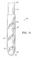
- FIG. 5Side views of the crumb-distributing implants 47 and 65 are shown in Figs. 5 and 6 respectively.
- the implant 47 shown in Fig. 5is a solid cylinder with screw threads 49 extending from the distal end to the terminal portion 51 of the implant.
- the terminal portion 51provides the means for attaching a prosthesis.
- the implant 65 shown in Fig. 6is similar in all respects to implant 47 except that it does not have the screw threads 49 and has in addition the coaxial hole 67 which connects to hole 57.
- At least one helical channel 53is embedded in the surface of the implant throughout the threaded portion.
- the intersection of the helical channel with the threadsresults in the threads having cutting edges which permit the implant to cut its own threads in bone tissue when it is installed.
- the threaded portionhas a tapered section 55 at the distal end to allow easy entry into the hole in the bone tissue.
- the primary purpose of the helical channel 53is to carry bone-fragment crumbs deposited in the bone-tissue hole prior to installation of implant 47 or implant 65 away from the distal end and distribute them throughout the threaded portion of the implant.
- the helical channel 53also provides a place for packing bone-fragment crumbs prior to installation of the implant.
- the threaded portion of the implant 47 and the corresponding portion of implant 65also include diametrical holes 57 in the implant at various levels along the axis of the implant and connecting to the helical channel 53.
- the diametrical holes 57may optionally pass all the way through the implant.
- the purpose of the holesis to provide receptacles for packing crumbled bone tissue prior to installation of the implant and avenues for bone tissue growth after installation.
- a hexagonal recessis provided in the proximal end 59 of implants 47 and 65 by means of which a user can engage the implant with a hexagonal driving tool for the purpose of screwing the implant into a receiving hole in bone tissue in the case of implant 47 or rotating the implant back and forth while pressing the implant into a hole in soft bone in the case of implant 65.
- the proximal end 59may also include a tapped hole below the hexagonal recess for the purpose of attaching a prosthesis to the implant.
- the terminal end 51can be tapered to assure that the attachment of the prosthesis is accomplished in a secure manner.
- Other types of driving-tool-engaging means and other types of prosthesis-attachment meanscan also be used.
- Implants 47 and 65are made of a biocompatible material such as pure titanium or a titanium alloy exemplified by Ti 6A1 4V. To encourage bone tissue growth in and around the implant, the implant may be coated or plasma-sprayed with hydroxyapatite.
- the diameter of the implantis typically in the range from 3 to 4 mm with lengths ranging from 6 to 16 mm.
- the diameter of a femoral implanttypically ranges from 6 mm to 16 mm with lengths ranging from 140 to 190 mm.
Landscapes
- Health & Medical Sciences (AREA)
- Orthopedic Medicine & Surgery (AREA)
- Life Sciences & Earth Sciences (AREA)
- Surgery (AREA)
- Animal Behavior & Ethology (AREA)
- Veterinary Medicine (AREA)
- Public Health (AREA)
- General Health & Medical Sciences (AREA)
- Engineering & Computer Science (AREA)
- Biomedical Technology (AREA)
- Oral & Maxillofacial Surgery (AREA)
- Heart & Thoracic Surgery (AREA)
- Nuclear Medicine, Radiotherapy & Molecular Imaging (AREA)
- Medical Informatics (AREA)
- Dentistry (AREA)
- Molecular Biology (AREA)
- Transplantation (AREA)
- Neurology (AREA)
- Epidemiology (AREA)
- Physical Education & Sports Medicine (AREA)
- Cardiology (AREA)
- Vascular Medicine (AREA)
- Prostheses (AREA)
- Surgical Instruments (AREA)
- Dental Prosthetics (AREA)
Abstract
Description
Claims (19)
- A device for making a hole in bone and collecting the bone fragments, the devicecomprising:a tubular saw having a proximal end, a distal end, and an interior surface, the tubular sawhaving a plurality of teeth at the distal end;a drill having a proximal end, a distal end, and an exterior surface, at least one helical channelbeing embedded in the exterior surface, the drill fitting within the tubular saw and being in intimatecontact with the interior surface of the tubular saw;a connector for rigidly connecting the tubular saw to the drill with the distal end of the tubularsaw coinciding with the distal end of the drill.
- The device of claim 1 wherein the helical channels extend from the distal end to anintermediate point between the distal end and the proximal end of the drill, the outside diameter ofthe drill being substantially less than the inside diameter of the tubular saw from the intermediatepoint to the proximal end.
- The device of claim 2 wherein the connection of the tubular saw to the drill causesthe proximal end of the tubular saw to be closed.
- A device for making a hole in bone and collecting the bone fragments, the devicecomprising:a tubular saw having a proximal end, a distal end, and an interior surface, the tubular sawhaving a plurality of teeth at the distal end;a drill having a proximal end, a distal end, and an exterior surface, the drill fitting within thetubular saw and being in intimate contact with the interior surface of the tubular saw;a connector for rigidly connecting the tubular saw to the drill with the distal end of the tubularsaw coinciding with the distal end of the drill.
- A device that is implanted in bone tissue and provides support for a prosthesis, thedevice being a cylinder comprising a main section and a terminal section, the end of the main sectionbeing rounded, the main section having at least one helical channel embedded in its surface.
- The device of claim 5 wherein the terminal section includes a means for attaching atool to enable a user to grip the device.
- The device of claim 5 wherein the terminal section includes a means for attaching aprosthesis.
- The device of claim 5 wherein there are one or more holes in and transverse to themain section.
- The device of claim 8 wherein the entrance to each hole is located in a helical channel.
- The device of claim 5 wherein there is an axial hole at the end of the main section.
- The device of claim 5 wherein the main section is threaded.
- A method for using the device of claim 5 comprising the steps:making a hole in bone tissue and collecting the bone fragments;crumbling the bone fragments;impregnating the device with the crumbled bone fragments;installing the device in the hole.
- The method of claim 12 further comprising the step:placing a portion of the crumbled bone fragments in the bone-tissue hole prior to installingthe device into the hole.
- A device that is implanted in bone tissue and provides support for a prosthesis, thedevice being a cylinder comprising a main section and a terminal section, the device having one ormore holes in and transverse to the main section.
- Implant apparatus comprising:a device for making a hole in bone and collecting the bone fragments;a device for crumbling the collected bone fragments;an implant device that can be impregnated with the crumbled bone fragments and implantedin bone tissue as a support for a prosthesis.
- A method for using the implant apparatus of claim 15 comprising the steps:making a hole in bone tissue and collecting the bone fragments using the hole-making device;crumbling the bone fragments using the bone-fragment crumbling device;impregnating the implant device with the crumbled bone fragments;implanting the implant device in the bone-tissue hole.
- The method of claim 16 further comprising the step:placing a portion of the crumbled bone fragments in the bone-tissue hole prior to implantingthe implant device in the hole.
- A method for providing a means for attaching a prosthesis to bone tissue comprisingthe steps:making a hole in bone tissue and collecting the bone fragments;crumbling the bone fragments;providing an implant to which the prosthesis can be attached and which can be impregnatedwith the crumbled bone fragments;impregnating the implant with the crumbled bone fragments;installing the impregnated implant in the bone-tissue hole.
- A method for implanting in bone tissue an implant device that provides support fora prosthesis, the implant device being a cylinder comprising a main section and a terminal section,the main section having at least one helical channel embedded in its surface, the method comprisingthe steps:making a hole in bone tissue and collecting the bone fragments;crumbling the bone fragments;impregnating the implant device with the crumbled bone fragments;installing the impregnated implant in the bone-tissue hole.
Applications Claiming Priority (3)
| Application Number | Priority Date | Filing Date | Title |
|---|---|---|---|
| US702948 | 1996-08-26 | ||
| US08/702,948US6604945B1 (en) | 1994-08-15 | 1996-08-26 | Method and apparatus for implantation |
| EP97110156AEP0826343B1 (en) | 1994-08-15 | 1997-06-20 | Apparatus for embedding an implant in bone tissue |
Related Parent Applications (2)
| Application Number | Title | Priority Date | Filing Date |
|---|---|---|---|
| EP97110156ADivisionEP0826343B1 (en) | 1994-08-15 | 1997-06-20 | Apparatus for embedding an implant in bone tissue |
| EP97110156.3Division | 1997-06-20 |
Publications (3)
| Publication Number | Publication Date |
|---|---|
| EP1430843A2true EP1430843A2 (en) | 2004-06-23 |
| EP1430843A3 EP1430843A3 (en) | 2004-06-30 |
| EP1430843B1 EP1430843B1 (en) | 2007-10-17 |
Family
ID=32991337
Family Applications (1)
| Application Number | Title | Priority Date | Filing Date |
|---|---|---|---|
| EP04006598AExpired - LifetimeEP1430843B1 (en) | 1996-08-26 | 1997-06-20 | Drill apparatus for embedding an implant in bone |
Country Status (4)
| Country | Link |
|---|---|
| EP (1) | EP1430843B1 (en) |
| JP (1) | JP4583331B2 (en) |
| DE (2) | DE69738227T2 (en) |
| ES (1) | ES2225915T3 (en) |
Cited By (14)
| Publication number | Priority date | Publication date | Assignee | Title |
|---|---|---|---|---|
| FR2882250A1 (en)* | 2005-02-24 | 2006-08-25 | Michel Isidori | GUIDING AND CUTTING DEVICES FOR THE PREPARATION OF BONE SITES IN IMPLANT SURGERY |
| WO2007144502A3 (en)* | 2006-06-14 | 2008-02-14 | Jean-Claude Yeung | Trephine designed for removal of a bone core and equipped with a device guiding it inside the bone and combining a drill bit and a tubular cutting tool |
| WO2010028811A1 (en)* | 2008-09-10 | 2010-03-18 | Nobel Biocare Services Ag | Device and procedure for implanting a dental implant |
| GB2476969A (en)* | 2010-01-18 | 2011-07-20 | Dental Devices Ltd Ab | Dental implant comprising a plurality of channels |
| US9579189B2 (en) | 2007-08-16 | 2017-02-28 | Smith & Nephew, Inc. | Helicoil interference fixation system for attaching a graft ligament to a bone |
| US9579188B2 (en) | 2010-03-10 | 2017-02-28 | Smith & Nephew, Inc. | Anchor having a controlled driver orientation |
| US9775702B2 (en) | 2010-03-10 | 2017-10-03 | Smith & Nephew, Inc. | Composite interference screws and drivers |
| US9788828B2 (en) | 2013-03-15 | 2017-10-17 | Smith & Nephew, Inc. | Miniaturized dual drive open architecture suture anchor |
| US9808298B2 (en) | 2013-04-09 | 2017-11-07 | Smith & Nephew, Inc. | Open-architecture interference screw |
| US9808337B2 (en) | 2010-03-10 | 2017-11-07 | Smith & Nephew, Inc. | Composite interference screws and drivers |
| US9901355B2 (en) | 2011-03-11 | 2018-02-27 | Smith & Nephew, Inc. | Trephine |
| US9924934B2 (en) | 2011-06-07 | 2018-03-27 | Smith & Nephew, Inc. | Surgical anchor delivery system |
| CN108742768A (en)* | 2018-07-06 | 2018-11-06 | 浙江复润医疗科技有限公司 | Micro-wound bone taking device |
| CN111358505A (en)* | 2020-03-24 | 2020-07-03 | 温州市中心医院 | Minimally invasive bone marrow biopsy sampling needle |
Families Citing this family (3)
| Publication number | Priority date | Publication date | Assignee | Title |
|---|---|---|---|---|
| JP5291719B2 (en)* | 2008-10-31 | 2013-09-18 | 株式会社ロバート・リード商会 | Bone fixation member and femoral fixation system |
| GB2523827A (en) | 2014-03-07 | 2015-09-09 | Nobel Biocare Services Ag | Dental implant |
| GB2523828A (en)* | 2014-03-07 | 2015-09-09 | Nobel Biocare Services Ag | Dental implant |
Family Cites Families (9)
| Publication number | Priority date | Publication date | Assignee | Title |
|---|---|---|---|---|
| CA1109746A (en)* | 1976-05-10 | 1981-09-29 | Shelby M. Baylis | Biopsy apparatus and methods of constructing and utilizing same |
| BE1002350A3 (en)* | 1988-08-02 | 1991-01-08 | Dury Georges Emile Ladislas | IMPLANT. |
| SU1725858A1 (en)* | 1989-07-31 | 1992-04-15 | Запорожский Областной Отдел Здравоохранения | Device for taking biopsy |
| US5324300A (en)* | 1991-10-25 | 1994-06-28 | Elias Elias G | Device for the controlled excision of tissue from a living body |
| JP2553396Y2 (en)* | 1991-12-25 | 1997-11-05 | 京セラ株式会社 | Artificial root |
| SE510158C2 (en)* | 1992-10-29 | 1999-04-26 | Medevelop Ab | Anchorage elements for supporting prostheses and the use of such anchorage elements for fixing dentures |
| SE9301407D0 (en)* | 1993-04-27 | 1993-04-27 | Medevelop Ab | BEFORE IMPLANTATION IN WEAVEN PROVIDED FOR THE ANCHORING ORGANIZATION FOR THE PROCESSING OF PROCESSES, ARTIFICIAL ARTICLE COMPONENTS OR LIKE |
| US5366374A (en)* | 1993-05-18 | 1994-11-22 | Vlassis James M | Dental implant |
| US5433606A (en)* | 1993-07-28 | 1995-07-18 | Core-Vent Corporation | Interlocking, multi-part endosseous dental implant systems |
- 1997
- 1997-06-20DEDE1997638227patent/DE69738227T2/ennot_activeExpired - Lifetime
- 1997-06-20EPEP04006598Apatent/EP1430843B1/ennot_activeExpired - Lifetime
- 1997-06-20ESES97110156Tpatent/ES2225915T3/ennot_activeExpired - Lifetime
- 1997-06-20DEDE1997630569patent/DE69730569T2/ennot_activeExpired - Lifetime
- 2006
- 2006-04-21JPJP2006117976Apatent/JP4583331B2/ennot_activeExpired - Fee Related
Cited By (20)
| Publication number | Priority date | Publication date | Assignee | Title |
|---|---|---|---|---|
| FR2882250A1 (en)* | 2005-02-24 | 2006-08-25 | Michel Isidori | GUIDING AND CUTTING DEVICES FOR THE PREPARATION OF BONE SITES IN IMPLANT SURGERY |
| WO2007144502A3 (en)* | 2006-06-14 | 2008-02-14 | Jean-Claude Yeung | Trephine designed for removal of a bone core and equipped with a device guiding it inside the bone and combining a drill bit and a tubular cutting tool |
| US9579189B2 (en) | 2007-08-16 | 2017-02-28 | Smith & Nephew, Inc. | Helicoil interference fixation system for attaching a graft ligament to a bone |
| US9463078B2 (en) | 2008-09-10 | 2016-10-11 | Nobel Biocare Services Ag | Device and procedure for implanting a dental implant |
| WO2010028811A1 (en)* | 2008-09-10 | 2010-03-18 | Nobel Biocare Services Ag | Device and procedure for implanting a dental implant |
| US8876530B2 (en) | 2008-09-10 | 2014-11-04 | Nobel Biocare Services Ag | Device and procedure for implanting a dental implant |
| GB2476969A (en)* | 2010-01-18 | 2011-07-20 | Dental Devices Ltd Ab | Dental implant comprising a plurality of channels |
| WO2011086529A1 (en) | 2010-01-18 | 2011-07-21 | A.B. Dental Devices Ltd. | Three dimensional lattice implant body |
| US9579188B2 (en) | 2010-03-10 | 2017-02-28 | Smith & Nephew, Inc. | Anchor having a controlled driver orientation |
| US9775702B2 (en) | 2010-03-10 | 2017-10-03 | Smith & Nephew, Inc. | Composite interference screws and drivers |
| US9931195B2 (en) | 2010-03-10 | 2018-04-03 | Smith & Nephew, Inc. | Composite interference screws and drivers |
| US9788935B2 (en) | 2010-03-10 | 2017-10-17 | Smith & Nephew, Inc. | Composite interference screws and drivers |
| US9808337B2 (en) | 2010-03-10 | 2017-11-07 | Smith & Nephew, Inc. | Composite interference screws and drivers |
| US9901355B2 (en) | 2011-03-11 | 2018-02-27 | Smith & Nephew, Inc. | Trephine |
| US9924934B2 (en) | 2011-06-07 | 2018-03-27 | Smith & Nephew, Inc. | Surgical anchor delivery system |
| US9788828B2 (en) | 2013-03-15 | 2017-10-17 | Smith & Nephew, Inc. | Miniaturized dual drive open architecture suture anchor |
| US9808298B2 (en) | 2013-04-09 | 2017-11-07 | Smith & Nephew, Inc. | Open-architecture interference screw |
| CN108742768A (en)* | 2018-07-06 | 2018-11-06 | 浙江复润医疗科技有限公司 | Micro-wound bone taking device |
| CN111358505A (en)* | 2020-03-24 | 2020-07-03 | 温州市中心医院 | Minimally invasive bone marrow biopsy sampling needle |
| CN111358505B (en)* | 2020-03-24 | 2022-11-29 | 温州市中心医院 | A minimally invasive bone marrow biopsy needle |
Also Published As
| Publication number | Publication date |
|---|---|
| JP4583331B2 (en) | 2010-11-17 |
| DE69730569D1 (en) | 2004-10-14 |
| DE69738227T2 (en) | 2008-07-17 |
| EP1430843A3 (en) | 2004-06-30 |
| ES2225915T3 (en) | 2005-03-16 |
| DE69730569T2 (en) | 2005-10-06 |
| DE69738227D1 (en) | 2007-11-29 |
| EP1430843B1 (en) | 2007-10-17 |
| JP2006212449A (en) | 2006-08-17 |
Similar Documents
| Publication | Publication Date | Title |
|---|---|---|
| US5676545A (en) | Method and apparatus for implantation | |
| US6604945B1 (en) | Method and apparatus for implantation | |
| US6135772A (en) | Method and apparatus for implantation | |
| JP4583331B2 (en) | Device for implantation into bone tissue | |
| US6666866B2 (en) | Spinal intervertebral implant insertion tool | |
| AU744371B2 (en) | Two-part intersomatic implant | |
| CA1237553A (en) | Artificial joint fixation to bone and sleeve therefor | |
| CA2269269C (en) | Device removal kit and method therefor | |
| US4624673A (en) | Device system for dental prosthesis fixation to bone | |
| US5522817A (en) | Absorbable surgical fastener with bone penetrating elements | |
| US4790753A (en) | Screw for dental implants | |
| US20030083747A1 (en) | Bone implant and isertion tools | |
| EP2255746B1 (en) | Implant fixture remover | |
| CA2205636A1 (en) | Setting tool for a fastening pin | |
| GB2210795A (en) | Oral implant | |
| JPH03503133A (en) | Surgical prosthetic implant device that promotes fusion between vertebrae | |
| US5342199A (en) | Cylindrical dental implant | |
| JP4658970B2 (en) | Prosthesis for surface replacement in the ball region of ball joints | |
| WO1991007932A1 (en) | Artificial hip-joint | |
| CA2179695A1 (en) | Dental root implant | |
| KR101720605B1 (en) | Dental Flattening Drill | |
| EP0471334A1 (en) | Absorbable surgical fastener with bone penetrating elements | |
| CN1929795B (en) | Anchoring element for use in bone | |
| EP3399941B1 (en) | Drill-less dental implant and uses thereof | |
| EP2740418A1 (en) | Surgical drill jig and surgical tool set |
Legal Events
| Date | Code | Title | Description |
|---|---|---|---|
| PUAI | Public reference made under article 153(3) epc to a published international application that has entered the european phase | Free format text:ORIGINAL CODE: 0009012 | |
| PUAL | Search report despatched | Free format text:ORIGINAL CODE: 0009013 | |
| 17P | Request for examination filed | Effective date:20040318 | |
| AC | Divisional application: reference to earlier application | Ref document number:0826343 Country of ref document:EP Kind code of ref document:P | |
| AK | Designated contracting states | Kind code of ref document:A2 Designated state(s):DE ES FR GB IT | |
| AK | Designated contracting states | Kind code of ref document:A3 Designated state(s):DE ES FR GB IT | |
| AKX | Designation fees paid | Designated state(s):DE ES FR GB IT | |
| GRAP | Despatch of communication of intention to grant a patent | Free format text:ORIGINAL CODE: EPIDOSNIGR1 | |
| GRAS | Grant fee paid | Free format text:ORIGINAL CODE: EPIDOSNIGR3 | |
| GRAA | (expected) grant | Free format text:ORIGINAL CODE: 0009210 | |
| AC | Divisional application: reference to earlier application | Ref document number:0826343 Country of ref document:EP Kind code of ref document:P | |
| AK | Designated contracting states | Kind code of ref document:B1 Designated state(s):DE ES FR GB IT | |
| REG | Reference to a national code | Ref country code:GB Ref legal event code:FG4D | |
| REF | Corresponds to: | Ref document number:69738227 Country of ref document:DE Date of ref document:20071129 Kind code of ref document:P | |
| PG25 | Lapsed in a contracting state [announced via postgrant information from national office to epo] | Ref country code:ES Free format text:LAPSE BECAUSE OF FAILURE TO SUBMIT A TRANSLATION OF THE DESCRIPTION OR TO PAY THE FEE WITHIN THE PRESCRIBED TIME-LIMIT Effective date:20080128 | |
| ET | Fr: translation filed | ||
| PLBE | No opposition filed within time limit | Free format text:ORIGINAL CODE: 0009261 | |
| STAA | Information on the status of an ep patent application or granted ep patent | Free format text:STATUS: NO OPPOSITION FILED WITHIN TIME LIMIT | |
| 26N | No opposition filed | Effective date:20080718 | |
| PGFP | Annual fee paid to national office [announced via postgrant information from national office to epo] | Ref country code:GB Payment date:20100825 Year of fee payment:14 | |
| PG25 | Lapsed in a contracting state [announced via postgrant information from national office to epo] | Ref country code:IT Free format text:LAPSE BECAUSE OF NON-PAYMENT OF DUE FEES Effective date:20080630 | |
| PGFP | Annual fee paid to national office [announced via postgrant information from national office to epo] | Ref country code:FR Payment date:20111128 Year of fee payment:15 | |
| PGFP | Annual fee paid to national office [announced via postgrant information from national office to epo] | Ref country code:DE Payment date:20111027 Year of fee payment:15 | |
| GBPC | Gb: european patent ceased through non-payment of renewal fee | Effective date:20120620 | |
| REG | Reference to a national code | Ref country code:FR Ref legal event code:ST Effective date:20130228 | |
| REG | Reference to a national code | Ref country code:DE Ref legal event code:R119 Ref document number:69738227 Country of ref document:DE Effective date:20130101 | |
| PG25 | Lapsed in a contracting state [announced via postgrant information from national office to epo] | Ref country code:DE Free format text:LAPSE BECAUSE OF NON-PAYMENT OF DUE FEES Effective date:20130101 Ref country code:FR Free format text:LAPSE BECAUSE OF NON-PAYMENT OF DUE FEES Effective date:20120702 Ref country code:GB Free format text:LAPSE BECAUSE OF NON-PAYMENT OF DUE FEES Effective date:20120620 |